Embed Size (px)
Citation preview

MASTER THESIS
TITLE: Design of a control and management system for frequency-and time-synchronous SDN networks.
MASTER: Master in Science in Telecommunication Engineering & Management
AUTHOR: Raul Suarez Marın
ADVISORS: Sebastia Sallent RibesDavid Rincon Rivera
DATE: June 6th, 2016


Tıtulo: Diseno de un sistema de gestion y control de redes sıncronas en tiempo y fre-cuencia basadas en SDN.
Autor: Raul Suarez Marın
Directores: Sebastia Sallent RibesDavid Rincon Rivera
Fecha: 6 de Junio de 2016
Resumen
Muchos servicios de telecomunicaciones tienen estrictos requisitos de sincronizacion. Latelefonıa celular (3G, 4G/LTE) es un claro ejemplo, en el que las estaciones base necesitanuna sincronizacion en frecuencia estable y de alta precision para obtener las frecuenciasportadoras y gestionar el acceso al medio de los terminales, ya que los recursos se com-parten en tiempo y en frecuencia. De la misma forma, se debe coordinar el handover determinales entre celdas adyacentes. Las redes 5G, con una mayor densidad de celdas ytasas de transmision mas elevadas requeriran una mayor precision en la sincronıa.
Por un lado, Synchronous Ethernet (SyncE) es una arquitectura basada en elementos Eth-ernet, caracterizados por su precio economico, madurez y escalabilidad, que proporcionade un arbol de distribucion de sincronizacion sobre una red, mediante un intercambio demensajes de control. Por otro lado tenemos PTP, un protocolo muy utilizado para trans-portar sincronıa en fase utilizado para sincronizar nodos en una red. Por encima de ambostenemos SDN, un nuevo paradigma de red en el que se abstrae el encaminamiento, de-sacoplando ası el plano de datos del plano de control. El control de la red reside enel controlador, que es centralizado y gestiona la red a base de reglas a traves de unasouthbound interface (OpenFlow). SDN facilita la virtualizacion de funciones de red, laoptimizacion de la gestion y una reduccion de los costes.
Se han propuesto dos soluciones para migrar SyncE y PTP a SDN. SyncE ha sido adap-tado a en SDN en la propuesta SDN-enabled SyncE y PTP mediante ReversePTP. SDN-enabled SyncE propone extensiones de OpenFLow 1.0 que habilitan en la red SDN uncontrol de la circulacion de ESMC PDUs, la lectura de estadısticas SyncE y la construccionde un arbol de sıncronia. ReversePTP propone extensiones a OpenFlow que permiten a lared obtener la base de tiempo (reloj) de cada nodo. De esta forma, el controlador conocelas desviaciones de los relojes respecto al suyo. Esta extension permite el handover co-ordinado de terminales entre celdas adyacentes. No obstante, no existe una propuestaque agrupe SDN, PTP y SyncE en una misma arquitectura totalmente sıncrona.
Esta tesis propone multiples extensiones estandar a OpenFlow para desplegar una redcompletamente sıncrona siguiendo la arquitectura FSS (Fully-Synchronous SDN). Paraello, se estudia e implementan SyncE y PTP en la arquitectura SDN. La extensiones ymodificaciones que se han propuesto se han desplegado y testeado sobre un entornoreal y los resultados iniciales muestran un buen rendimiento.


Title: Design of a control and management system for frequency-and time-synchronousSDN networks.
Author: Raul Suarez Marın
Advisors: Sebastia Sallent RibesDavid Rincon Rivera
Date: June 6th, 2016
Overview
Many of today’s telecommunications systems rely on strict timing and synchronization re-quirements. This is the case of cellular telephony (3G, 4G/LTE), where base stations needaccurate and stable frequency clocks in order to obtain their carrier radio frequencies, arbi-trate the frequency- and time-shared access of terminals, and coordinate the handover ofterminals between adjacent cells. The imminent deployment of 5G networks, with a muchhigher density of cells and speed, will further increase the need for synchronization.
On the one hand, Synchronous Ethernet (SyncE) is a well-known, cheap, scalable Eth-ernet data plane, with the addition of special messages that convey frequency synchro-nization information. On the other hand, Precision Time Protocol (PTP) is a widely usedprotocol to transport time information, and used to synchronize nodes in networks. On topof that, SDN is a new networking paradigm that provides an abstraction of the forwardingfunction, decoupling the data plane from the control plane. The control of the network ismoved to the controller, an external centralized entity that manages the network config-uration based on policies through a southbound interface, for example OpenFlow. SDNarchitecture opens the way to the virtualization of network functions, the global optimiza-tion of network operations, and reduces operational costs.
Two solutions proposed moving SyncE and PTP to SDN networks: SyncE has been in-troduced in SDN with the SDN-enabled SyncE networks and PTP with the ReversePTP.SDN-enabled SyncE proposed extensions to OpenFlow 1.0 which enables the SDN net-work to control the circulation of ESMC PDU, the possibility of transmitting SyncE statisticsand to build synchronization trees based on SyncE. ReversePTP proposed extensions toOpenFlow which enabled the SDN network to request the time to each node, so the SDNcontrollers know clock offsets between slave clocks (network elements) and itself (masterclock). These extensions allow to coordinate the handover of terminals between adjacentcells in mobile networks and a kind of PTP. However, there is no solution in the literaturewhich proposes an SDN+PTP+SyncE (i.e. a full synchronous) solution.
This master thesis proposes multiple standard extensions of the OpenFlow protocol inorder to deploy Fully-Synchronous SDN (FSS) networks. For that, SyncE and PTP arestudied and implemented in the SDN architecture. The proposed extensions and modifi-cations have been deployed and successfully tested in a real environment. Results showeda good performance on PTP time-stamping.


Este trabajo va dedicado principalmente a mis padresFrancisco Suarez y Conchi Marın, a mi hermana Inesy a mis abuelos, que siempre han estado junto a mi yque me han dado siempre todo y mas, pero sobretodoporque han permitido que esto sea posible.
A Sebastia Sallent y a David Rincon, por ser unos ex-celentes docentes y mis mentores, que me han aconse-jado y ayudado durante el proyecto.
A todos vosotros, ¡Muchas gracias!


CONTENTS
CHAPTER 1. Introduction and problem statement . . . . . . . . . . . 1
CHAPTER 2. Synchronization in networks . . . . . . . . . . . . . . . . 3
2.1. Synchronous Ethernet (SyncE) . . . . . . . . . . . . . . . . . . . . . . . . 32.1.1. Architecture . . . . . . . . . . . . . . . . . . . . . . . . . . . . . . 4
2.1.2. Messages . . . . . . . . . . . . . . . . . . . . . . . . . . . . . . . 5
2.1.3. Operations . . . . . . . . . . . . . . . . . . . . . . . . . . . . . . . 5
2.2. Precision Time Protocol (PTP) . . . . . . . . . . . . . . . . . . . . . . . . . 82.2.1. Architecture . . . . . . . . . . . . . . . . . . . . . . . . . . . . . . 8
2.2.2. Protocol . . . . . . . . . . . . . . . . . . . . . . . . . . . . . . . . 9
2.2.3. Messages . . . . . . . . . . . . . . . . . . . . . . . . . . . . . . . 12
2.2.4. Best Master Clock Algorithm (BMCA) . . . . . . . . . . . . . . . . . 14
2.3. Summary . . . . . . . . . . . . . . . . . . . . . . . . . . . . . . . . . . . . 14
CHAPTER 3. Software-Defined Networking architecture . . . . . . . 15
3.1. Software-Defined Networking . . . . . . . . . . . . . . . . . . . . . . . . . 153.1.1. OpenFlow . . . . . . . . . . . . . . . . . . . . . . . . . . . . . . . 16
3.1.2. Open vSwitch . . . . . . . . . . . . . . . . . . . . . . . . . . . . . 17
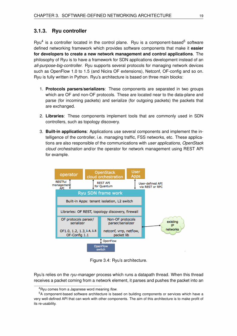
3.1.3. Ryu controller . . . . . . . . . . . . . . . . . . . . . . . . . . . . . 19
3.2. Synchronization in SDN . . . . . . . . . . . . . . . . . . . . . . . . . . . . 203.2.1. SDN-enabled SyncE networks . . . . . . . . . . . . . . . . . . . . 20
3.2.2. ReversePTP . . . . . . . . . . . . . . . . . . . . . . . . . . . . . . 22
3.3. Summary . . . . . . . . . . . . . . . . . . . . . . . . . . . . . . . . . . . . 24
CHAPTER 4. Fully-Synchronous SDN (FSS) . . . . . . . . . . . . . . . 25
4.1. Use cases . . . . . . . . . . . . . . . . . . . . . . . . . . . . . . . . . . . . 254.1.1. FSS/SyncE . . . . . . . . . . . . . . . . . . . . . . . . . . . . . . 25
4.1.2. FSS/PTP . . . . . . . . . . . . . . . . . . . . . . . . . . . . . . . . 27
4.2. Architecture . . . . . . . . . . . . . . . . . . . . . . . . . . . . . . . . . . . 28
4.3. Summary of the required extensions . . . . . . . . . . . . . . . . . . . . . 30
4.4. Environment . . . . . . . . . . . . . . . . . . . . . . . . . . . . . . . . . . . 31

4.5. Implementation . . . . . . . . . . . . . . . . . . . . . . . . . . . . . . . . . 324.5.1. Data plane in detail: Open vSwitch . . . . . . . . . . . . . . . . . . 32
4.5.2. Control plane in detail: Ryu . . . . . . . . . . . . . . . . . . . . . . 39
4.6. Summary . . . . . . . . . . . . . . . . . . . . . . . . . . . . . . . . . . . . 47
CHAPTER 5. Results . . . . . . . . . . . . . . . . . . . . . . . . . . . . . . 49
5.1. Unit tests . . . . . . . . . . . . . . . . . . . . . . . . . . . . . . . . . . . . 49
5.2. System performance . . . . . . . . . . . . . . . . . . . . . . . . . . . . . . 495.2.1. CPU and network throughput . . . . . . . . . . . . . . . . . . . . . 50
5.2.2. Time-stamp accuracy . . . . . . . . . . . . . . . . . . . . . . . . . 51
5.3. Summary . . . . . . . . . . . . . . . . . . . . . . . . . . . . . . . . . . . . 53
CHAPTER 6. Conclusions and future lines of study . . . . . . . . . 55
6.1. Conclusions . . . . . . . . . . . . . . . . . . . . . . . . . . . . . . . . . . . 55
6.2. Future lines of study . . . . . . . . . . . . . . . . . . . . . . . . . . . . . . 56
6.3. Environmental impact . . . . . . . . . . . . . . . . . . . . . . . . . . . . . 57
Bibliography . . . . . . . . . . . . . . . . . . . . . . . . . . . . . . . . . . . . 59
Acronyms . . . . . . . . . . . . . . . . . . . . . . . . . . . . . . . . . . . . . . 63
APPENDIX A. List of Synchronous Ethernet QL . . . . . . . . . . . . 67
APPENDIX B. OpenDaylight . . . . . . . . . . . . . . . . . . . . . . . . . . 69
APPENDIX C. SDN-enabled SyncE operations . . . . . . . . . . . . . 71
APPENDIX D. OpenFlow 1.3.0 Overview . . . . . . . . . . . . . . . . . . 73
APPENDIX E. SyncE driver emulation database . . . . . . . . . . . . 89
APPENDIX F. Open vSwitch implementation . . . . . . . . . . . . . . 91
F.1. Flow implementation . . . . . . . . . . . . . . . . . . . . . . . . . . . . . . 91
F.2. Testing . . . . . . . . . . . . . . . . . . . . . . . . . . . . . . . . . . . . . . 96

APPENDIX G. Open vSwitch files description . . . . . . . . . . . . . . 101


LIST OF FIGURES
2.1 Synchronization and traceability of signals in SyncE networks. . . . . . . . 42.2 Synchronization network model for SyncE [2]. . . . . . . . . . . . . . . . . 52.3 ESMC PDU data structure. . . . . . . . . . . . . . . . . . . . . . . . . . . 62.4 State machine diagram upon reception of an ESMC PDU. . . . . . . . . . . 82.5 A grandmaster synchronizes a slave. This slave becomes a master for the
slave connected to it [15]. . . . . . . . . . . . . . . . . . . . . . . . . . . . 92.6 Example of a Master-Slave hierarchy. . . . . . . . . . . . . . . . . . . . . . 102.7 Delay Request-Response Mechanism. . . . . . . . . . . . . . . . . . . . . 102.8 Peer Delay Mechanism. . . . . . . . . . . . . . . . . . . . . . . . . . . . . 112.9 PTP delay measurement block diagram [15]. . . . . . . . . . . . . . . . . . 122.10 PTP Message encapsulation over Ethernet (left) and over UDP (right). . . . 13
3.1 SDN Architecture [16]. . . . . . . . . . . . . . . . . . . . . . . . . . . . . 163.2 Conceptual view of the forwarding plane of an OpenFlow Switch. . . . . . . 183.3 Treatment of incoming packets in Open vSwitch. . . . . . . . . . . . . . . . 183.4 Ryu’s architecture. . . . . . . . . . . . . . . . . . . . . . . . . . . . . . . 193.5 Ryu’s internal implementation. . . . . . . . . . . . . . . . . . . . . . . . . 203.6 SDN-enabled SyncE network architecture. . . . . . . . . . . . . . . . . . . 213.7 ReversePTP network architecture. . . . . . . . . . . . . . . . . . . . . . . 23
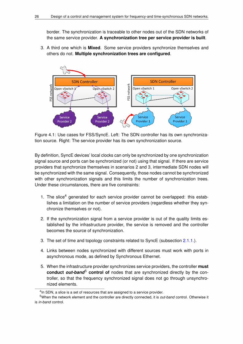
4.1 Use cases for FSS/SyncE. Left: The SDN controller has its own synchro-nization source. Right: The service provider has its own synchronizationsource. . . . . . . . . . . . . . . . . . . . . . . . . . . . . . . . . . . . . 26
4.2 An SDN switch that implements algorithms is not compatible with the SDNparadigm. Therefore, it is seen as an SDN switch connected to a non-SDNswitch. . . . . . . . . . . . . . . . . . . . . . . . . . . . . . . . . . . . . . 27
4.3 Use cases for FSS/PTP. . . . . . . . . . . . . . . . . . . . . . . . . . . . . 284.4 FSS/PTP architecture. . . . . . . . . . . . . . . . . . . . . . . . . . . . . 304.5 FSS controller architecture. . . . . . . . . . . . . . . . . . . . . . . . . . . 314.6 Datapath processing [25]. Functions including time-stamp are circled in red. 334.7 Experimenter structures for match options and actions. . . . . . . . . . . . 364.8 MULTIPART REQUEST message structure overview. . . . . . . . . . . . . 374.9 EXPERIMENTER message structure overview. . . . . . . . . . . . . . . . 38
5.1 Scenario used in the performance tests. . . . . . . . . . . . . . . . . . . . 505.2 Throughput evaluation. . . . . . . . . . . . . . . . . . . . . . . . . . . . . 515.3 Lineal evolution of the throughput. . . . . . . . . . . . . . . . . . . . . . . 515.4 Time-stamp accuracy. . . . . . . . . . . . . . . . . . . . . . . . . . . . . . 525.5 Time-stamp accuracy. . . . . . . . . . . . . . . . . . . . . . . . . . . . . . 525.6 Statistical distribution of the time-stamp error. . . . . . . . . . . . . . . . . 53
B.1 OpenDaylight Lithium structure for OpenFlow 1.3. . . . . . . . . . . . . . . 69
C.1 Interaction between nodes. . . . . . . . . . . . . . . . . . . . . . . . . . . 72


LIST OF TABLES
4.1 Current implementation and new proposals of FSS/SyncE. . . . . . . . . . 29
A.1 Quality Level values. . . . . . . . . . . . . . . . . . . . . . . . . . . . . . 67
G.1 Files modified to implement proposed OpenFlow extensions. . . . . . . . . 103

LIST OF CODES2.1 PTP message format. . . . . . . . . . . . . . . . . . . . . . . . . . . . . 132.2 Header of a PTP message, common in all PTP messages. . . . . . . . . . 134.1 Hidden flow entries. . . . . . . . . . . . . . . . . . . . . . . . . . . . . . 344.2 Experimenter match structure for synce-event-flag and PTP domain. . . . . 364.3 Experimenter action structure for QL rewriting (FSS/SyncE) and PTP time-
stamping (FSS/PTP). . . . . . . . . . . . . . . . . . . . . . . . . . . . . . 374.4 MULTIPART REPLY message structure. . . . . . . . . . . . . . . . . . . . 384.5 Experimenter message for configuring network elements. . . . . . . . . . . 394.6 Dump flows from a switch taking part in FSS/SyncE and FSS/PTP. . . . . . 414.7 FSS experimenter OXM class definition. . . . . . . . . . . . . . . . . . . . 424.8 FSS experimenter OXM class definition. . . . . . . . . . . . . . . . . . . . 424.9 Generation of Flow Mod messages with synce event flag match (add flow
function), QL rewriting (add flow synce rewrite ql function) and PTP time-stamping (add flow ptp) simple switch 13 fss.py . . . . . . . . . . . . . . . 43
4.10 Multipart Request of FSS information in simple switch 13 fss.py. . . . . . . 444.11 FSS configuration with Experimenter message in simple switch 13 fss.py. . 444.12 Function executed in the Synchronous Manager when it receives a FEA-
TURES REPLY message. . . . . . . . . . . . . . . . . . . . . . . . . . . 444.13 Function executed in the Synchronous Manager when it receives a MULTI-
PART REPLY message. . . . . . . . . . . . . . . . . . . . . . . . . . . . 454.14 Function executed during a selection process. . . . . . . . . . . . . . . . . 454.15 Function executed in the Synchronous Manager when it receives a PACKET IN
message. . . . . . . . . . . . . . . . . . . . . . . . . . . . . . . . . . . . 46E.1 Directory of the database in an Open vSwitch instance running 6 virtualized
switches. . . . . . . . . . . . . . . . . . . . . . . . . . . . . . . . . . . . 89E.2 Structure of the database holding QL and signal-fail values. . . . . . . . . . 89F.1 sw flow key struct. . . . . . . . . . . . . . . . . . . . . . . . . . . . . . . 92F.2 MFF SYNCE EVENT FLAG definition. . . . . . . . . . . . . . . . . . . . 93F.3 Code that perform actions in user-space. . . . . . . . . . . . . . . . . . . 94F.4 Code that perform actions in kernel-space. . . . . . . . . . . . . . . . . . 95F.5 Code that enables sk buff time-stamping. . . . . . . . . . . . . . . . . . . 95F.6 Test for match/action validation. . . . . . . . . . . . . . . . . . . . . . . . 96F.7 Test for FSS statistics validation. . . . . . . . . . . . . . . . . . . . . . . . 97F.8 Test for FSS configure port and asynchronous statistics validation. . . . . . 97F.9 Test for FSS asynchronous statistics validation. . . . . . . . . . . . . . . . 98F.10 Test for ESMC PDU parsing validation. . . . . . . . . . . . . . . . . . . . 98F.11 Test for PTP packet parsing validation. . . . . . . . . . . . . . . . . . . . . 99


CHAPTER 1. INTRODUCTION AND PROBLEMSTATEMENT
Many of today’s telecommunications systems rely on strict timing and synchronization re-quirements. This is the case of cellular telephony (3G, 4G/LTE), where base stations needaccurate, stable frequency clocks in order to obtain their carrier radio frequencies, arbitratethe frequency-and-time-shared access of terminals, and coordinate the handover of termi-nals between adjacent cells [1]. The imminent deployment of 5G networks, with a muchhigher density of cells, will further increase the need for synchronization.
Currently, circuit-based, time-division multiplexing (TDM) transmission technologies suchas SDH/SONET provide clock distribution over the data transmission plane, by defininga tree-based hierarchy of clocks. Clocks differ in frequency and phase accuracy, andholdover stability, and can be classified in different strata or quality levels. The PrimaryReference Clock (PRC), at the top of the synchronization network tree (stratum 1), is themaster reference to which other, lower-quality clocks (stratum 2, 3, ...) lock and correcttheir inherent frequency drift. By designing a synchronization network that guaranteesthe traceability of any equipment’s clock to the PRC, the line clock of TDM signals thatfeed the telecommunications equipment (usually E1 or T1 interfaces) ensures the requiredsynchronization at the edge equipment.
However, telecommunications operators are migrating from circuit-based, time-divisionmultiplexing (TDM) transmission systems to packet-switching technologies, due to the in-herent advantages of the latter approach (higher flexibility, lower operation costs (OPEX),economies of scale, and better integration with higher layer IP-based services, amongothers). Again, this is the case of 4G/LTE/5G networks, with their “all-IP” architecture.This raises a question: is there any technological solution able to integrate both packetswitching and synchronization distribution capabilities?
Synchronous Ethernet (SyncE) [2] is such a technology: the well-known, cheap, scalableEthernet data plane, with the addition of special messages that convey synchronizationinformation, achieves frequency synchronization. Regarding frequency, SyncE nodes aresimilar to SDH/SONET nodes: the reference clock is obtained from the signal receivedfrom a specific input port and it is used to correct the local clock. The regenerated fre-quency signal is applied to the output port clock [3]. Nodes exchange SynchronizationStatus Messages (SSM) in order to identify the quality of the clocks, and thus deciding (ina distributed way) the best topology for the tree-like clock chain.
Precision Time Protocol (PTP) defined in the IEEE-2008 [4] is a technology that comple-ments SyncE. PTP describes a hierarchical master-slave architecture for clock distribution.PTP enables the precise transfer phase to synchronize clocks over packet-based Ethernetnetworks. For that, it uses traffic time-stamping with sub-nanoseconds granularity to de-liver the very high accuracies of synchronisation needed to ensure stability. Time-stampsbetween master and slave devices are sent with specific PTP packets and in its basic formthe protocol is administration-free.
In the networking landscape, Software-Defined Networking (SDN) has recently emergedas a new network management paradigm. SDN separates the control and data planes andintroduces a centralized controller, an external centralized entity that manages the networkconfiguration and forwarding functions based on policies defined by the network operator.
1

2 Design of a control and management system for frequency-and time-synchronous SDN networks.
[5]. The controller communicates with simple, cheap switching nodes through standard-ized interfaces, being OpenFlow (OF) the most popular [6]. Then, SDN turns networksinto programmable networks where switching decisions are based on flows and not on thedestination addresses [5]. It is now possible to dynamically or automatically configure orreconfigure the orchestration of IT infrastructures from the network up to applications com-bining the SDN with network function virtualization (NFV) [7]. This centralized architectureopens the way to the virtualization of network functions, the global optimization of networkoperations and reduces operational costs. The convergence of wired, wireless and cellu-lar technologies is enabling the emergence of fully programmable IT infrastructures, butin order to meet these challenges, SDN still has to solve some open issues. A criticalcharacteristic in the new 5G architecture technologies is its synchronous nature, and thatposes some challenges in the design of packet-switched access backbone networks.
To the best of our knowledge, SyncE has been introduced in SDN for the first time withthe SDN-enabled SyncE networks by Raul Suarez et al. [9] where the authors proposeextensions to OpenFlow 1.0 which enable the SDN network to control the circulation ofESMC PDUs, the possibility of transmitting SyncE statistics and to build synchronizationtrees based on SyncE. However, in this case OpenFlow was not extended in an standardway so OpenFlow does not support such extensions. Moreover, the treatment of statisticspresented in the aforementioned work can be enhanced.
On the other hand, PTP has been introduced as well in SDN with ReversePTP by Mizrahiet al. [8]. ReversePTP proposed extensions to OpenFlow which enabled the SDN networkto request the time to each node, so the SDN controller knows the clock offsets betweenthe slave clocks (network elements) and itself (master clock). These extensions allow tocoordinate the handover of terminals between adjacent cells in mobile networks. Addition-ally, they take advantage of this feature and propose that the SDN controller acts as a bigboundary clock in a PTP network.
Given these two approaches for SyncE and PTP, we propose the FSS (Fully-SynchronousSDN) networks which implement SyncE (FSS/SyncE) and PTP (FSS/PTP) in a unifiedarchitecture. FSS networks offer a fully-synchronous solution that is 100 % compliantwith OpenFlow 1.3 thanks to the fact that extensions are proposed as vendor-specificextensions which are part of the standard and is also compatible with traditional packet-switched networks since the SDN network will be transparent for them (as the SyncE andPTP services can be used over the SDN network). The FSS architecture eases the wayto migrate synchronous networks to SDN which enhances operations and management,thus reducing OPEX.
This project discusses the implementation of SyncE and PTP in SDN networks and presentsresults from a real implementation. The rest of the work is organized as follows. Chapters2 reviews Synchronous Ethernet and PTP and Chapter 3 explains the Software-DefinedNetworking architecture. Chapter 4 presents a high-level functional description of the SDN-related operations in SyncE and PTP networks, followed by the details. Chapter 5 presentsthe results and ends with conclusions and future lines of research in Chapter 6.

CHAPTER 2. SYNCHRONIZATION INNETWORKS
Synchronization is a need in networks where time is an asset, such as in mobile networks.To that end, standardization bodies such as the ITU and the IEEE have created ways oftransmitting synchronization. The ITU defines three ways for transmitting synchronizationin a network by means of timing flows [10]:
1. MESSAGE timing flow: The synchronization is obtained from the messages ex-changed between nodes. These messages belong to the application layer1. Thismeans that an specific application must run between two or more nodes to obtainthe synchronization. PTP is a protocol that uses message timing flows. Fromthe information of those messages, the system is modified in the physical layer.
2. SERVICE timing flow: The synchronization relates to a certain service (e.g. PDH2).When a connection is established between two endpoints, a synchronization serviceis created independently from other connections. Intermediate nodes are transpar-ent to the synchronization service.
3. PHYSICAL timing flow: The synchronization is obtained from the actual signalused to transmit data which is directly used to synchronize the local clock.This timing flow is node-to-node, i.e. without intermediate nodes. SynchronousEthernet is a physical timing flow.
This chapter describes the architecture, messages and operations of Synchronous Eth-ernet (SyncE) and Precision Time Protocol (PTP) in order to provide the reader with thebackground to understand how SyncE and PTP can be integrated in the SDN architecture.
2.1. Synchronous Ethernet (SyncE)
Synchronous Ethernet has been defined and standardized by the ITU in order to extendthe Ethernet layer to add frequency synchronization without loosing compatibility with na-tive Ethernet and SDH devices. SyncE synchronizes devices in frequency, but not inphase.
SyncE devices follow a physical timing flow architecture and manage messages to deter-mine the quality of internal clocks of neighbour devices, leading to configurations on thehardware (physical layer) to obtain the best synchronization signal available. Once thelocal clock is synchronized, ports can be synchronized with it. The synchronization signalis traceable to other devices, so a master device can synchronize an entire network.
Synchronous Ethernet is raised as an SDH evolution of packet-switched networks3 [10],so both must maintain compatibility to allow unified synchronization networks. A key is-sue for SyncE in this SDH evolution is to provide the required inter-networking between
1The OSI model by layer specifies seven layers from upper to lower: application, presentation, session,transport, network, link and physical. The application is the upper layer in which users run applications.
2PDH is a service that synchronizes flows of data at bit level (link layer in the OSI model).3SDH follows a circuit-switched network model while SyncE follows a packet-switched network model.
3

4 Design of a control and management system for frequency-and time-synchronous SDN networks.
SDH and SyncE equipment. The mechanisms to ensure compatibility are found funda-mentally in three ITU-T recommendations: G.8261 [11] (the SyncE architecture), G.8262[12] (performance and clock characteristics) and G.8264 [10] (message definitions).
2.1.1. Architecture
SyncE networks comprise asynchronous devices (clock accuracy of ± 100 ppm) and syn-chronous devices, which rely on a local Ethernet Equipment Clock (EEC, G.8262) withan accuracy better or equal to ± 4.6 ppm. Asynchronous devices do not take part inthe synchronization network but must coexist with synchronous devices. This is, linksbetween asynchronous and synchronous devices must operate correctly even though de-vices’ clocks have different accuracies.
In SyncE, the quality level (QL) of a clock is defined by its accuracy. SyncE devices can beattached to external clocks or not. A SyncE device that is not attached to any clock relieson the local clock with QL QL-EEC1 or QL-EEC2. The most common external clocks arePrimary Reference Clocks (PRC, G.811) with QL QL-PRC and Synchronization SupplyUnits (SSU, G.812) with QL QL-SSU-A or QL-SSU-B. The complete list of possible QLcan be found in Appendix A.1.
A synchronized device can trace its synchronization signal to other devices in a network,enabling the creation of a synchronization network (Figure 2.1). For that, a not-already-synchronized device detects the QL of the signals coming from adjacent nodes and de-cides through a selection process which is the best synchronization source for it.
Figure 2.1: Synchronization and traceability of signals in SyncE networks.
Each synchronous device runs a selection process to end up building a logical synchro-nization tree4. The synchronization source (root) of this tree is the best quality device(usually QL-PRC). The tree is built following certain constraints (ITU-T G.803 [13]):
1. Maximum chain of 20 consecutive EECs so that jitter and wander5 values aremaintained within the limits. If the chain has to be extended, the next clock musthave a higher quality (for example, an SSU-A).
2. Maximum of 60 EECs in a single chain, no matter if there are higher quality clocksin between or not.
4A tree network is a combination of two or more star networks connected together.5A phase fluctuation of a signal is an oscillating movement with an amplitude and a frequency. If this
frequency is more than 10 Hz, it is known as jitter, and when it is less than that, it is called wander.

CHAPTER 2. SYNCHRONIZATION IN NETWORKS 5
3. Maximum of 10 SSUs in a single chain.
It is important to emphasize that the synchronization network is always a tree (figure 2.2).Otherwise, there can be synchronization loops leading to instability. This can happen asnetwork operators tend to have a backup PRC in case the main PRC fails. In this case, thenetwork operator must engineer the possible synchronization trees and configure carefullyevery device so a synchronization loop never appears.
Figure 2.2: Synchronization network model for SyncE [2].
Some messages and operations have been defined by the ITU-T in order to enforce thisrequirement, as we will see in the following sections.
2.1.2. Messages
Nodes need to discover what is the QL of their neighbours in order to run a selectionprocess and create the synchronization tree. Special QL values are used to avoid syn-chronization loops, as explained in subsection 2.1.3.3.
An Ethernet Synchronization Message Channel (ESMC) is established between adjacentsynchronous devices. This channel relies on the Organization Specific Slow Protocol(OSSP) specified in the IEEE 802.3ay standard and is used to exchange Synchroniza-tion Status Messages (SSM) between nodes. OSSP limits the channel to 10 messagesper second [10].
ESMC PDU data fields comprise the identifier and version of the ESMC channel, an event-flag field (determines if the ESMC PDU has been event generated or not) and a QL TLV,which contains the SSM code of the QL (Figure 2.3).
2.1.3. Operations
The configuration of a SyncE device comprises:

6 Design of a control and management system for frequency-and time-synchronous SDN networks.
Figure 2.3: ESMC PDU data structure.
• Operation mode: Ports can work in either non-synchronous or synchronousmode. A non-synchronous port does not establish an ESMC.
• Ports can be prioritized over others. Priority is set in a value range of [0-65535]being 0 the lowest and 65535 the highest priority [14].
• QL-ENABLED flag is set if the device should consider the QL of the adjacent nodesfor the selection process.
• A signal-fail flag is defined for each port and is set when the port cannot be usedto get synchronization. If QL-ENABLED is set, a QL-FAILED state is achieved in-stead. To avoid intermittent signal fail information, a hold-off timer must expire beforeapplying any operation to that port.
• The Information Timer (IT) defines a time interval on which an ESMC may not bereceived in a port. It is usually configured to 5 seconds.
• The Wait-To-Restore (WTR) defines a time interval on which an ESMC may beignored. It is usually configured to 12 minutes.
A selection process is conducted when certain events occur or ESMC PDUs indicate so.The selection process can trigger new ESMC PDUs that inform topology changes.
2.1.3.1. Selection process
The selection process is an algorithm that decides which port is the best in terms of priorityand quality. It is triggered when is detected a change in QL or signal-fail.
1. If QL-ENABLED is set, arrange the valid ports in terms of QL (from higher to lowerpriority), and remove the low quality ports from the selection process.
2. Remove the ports in QL-FAILED or signal-failed state.
3. Order ports by priority, and remove the low priority ports from the selection process.
4. Get the best port(s).

CHAPTER 2. SYNCHRONIZATION IN NETWORKS 7
• If there are no ports available, the device enters into holdover state (no externalsynchronization).
• If there is only one port available, that port is chosen.
• If there are more than one port available, maintain the port that is currentlybeing used if possible; otherwise, choose randomly. If there is the need tosynchronize an external SSU clock attached to the device, synchronize it withone of the remaining ports.
2.1.3.2. Defect in a synchronization source
Synchronous Ethernet must be able to detect failures (for example, detect ports that cannotbe used anymore to synchronize the main clock). In that case, the port reaches a QL-FAILED/signal-fail state if the defect is maintained during a hold-off time (0.3 s - 1.8 s)[14]. Afterwards, this change is notified to the selection process for removing the affectedport(s) from the candidates list during WTR seconds. If the failure has been fixed after thattime, the ports is considered again in the selection process.
2.1.3.3. Generation of ESMC PDU
ESMC PDUs can be generated as a heart-beat or by event:
1. Heart-beat: Used for continuous quality level reporting. The device announces inevery port its own QL. However, in the port that is currently used for synchronizingthe announced QL is QL-DNU (Do Not Use). This avoids possible synchronizationloops.
2. Events: When there is a change in QL or signal-fail.
If the QL of a node changes, the selection process is triggered and different time con-straints are defined for the generation of new ESMC PDUs [14]:
1. No port is available and the device announces its native QL in a timeTHM = [300, 2000] ms.
2. The port is maintained and the device announces its QL in less than TNSM = 200 ms.
3. The synchronization port is changed and the device announces its QL in a timeTSM = [180, 500] ms.
2.1.3.4. Reception of ESMC PDU
Nodes receive information from other nodes. If the QL changes, the node goes through aselection process and a new synchronization port can be chosen. Afterwards, this eventis notified to adjacent nodes. If a device does not receive an ESMC PDU for more than ITseconds on a certain port, the QL value of the adjacent node is to be considered QL-DNU(Do Not Use). In this case, this port is removed from the selection process during a WTRseconds. Figure 2.4 shows the state machine diagram of the operations triggered by thereception of an ESMC PDU.

8 Design of a control and management system for frequency-and time-synchronous SDN networks.
Figure 2.4: State machine diagram upon reception of an ESMC PDU.
2.2. Precision Time Protocol (PTP)
PTP has been defined and standardized by the IEEE as IEEE1588 in 2002. PTP wasrevised in 2008 and PTP Version 2 was released [15]. PTP is a protocol that follows amessage timing flow scheme to synchronizes nodes in phase. PTP enables the precisetransfer of time to synchronize clocks over packet-based Ethernet networks. For that, ituses traffic time-stamping with sub-nanoseconds granularity to deliver the very high ac-curacies of synchronisation needed to ensure stability. Timestamps between master andslave devices are sent with specific PTP packets and in its basic form the protocol isadministration-free. PTP follows a master-slave architecture and the goal of a master de-vice is that the slave clock ends up synchronized in time (phase). The performance of PTPis dependant on the precision of the timestamps. Timestamps of incoming and outgoingpackets need to be recorded to ensure synchronization between master and slave. Differ-ences in time between clocks (clock offsets) need to be evaluated as well to ensure thatthey are within their specified limits.
2.2.1. Architecture
The architecture is based on a master-slave approach. A master (ideally synchronizedby a radio clock or a GPS receiver) synchronizes the slaves connected to it. Then, thosebecome master to other clocks connected to them, and they synchronize the respectiveslaves connected to them (Figure 2.5). At the end, all clocks lead back and ultimatelyderive their time from the grandmaster clock. The topology is always a tree with hierarchylevels and there is a unique tree per PTP domain6. The hierarchy levels are defined bythe clock quality of each network device. They communicate the quality of the clock usingAnnounce messages.
Master and slave network devices are kept synchronized by the transmission of time-stamps sent within the PTP messages. These timestamps refer to a very precise measure-ment of the time on which the PTP message left the node and of the time on which the PTPmessage was received by the receiver. Additionally, the measurement of a time-stamp can
6Multiple PTP domains can coexist in the same network but a device cannot belong to more than onePTP domain.

CHAPTER 2. SYNCHRONIZATION IN NETWORKS 9
Figure 2.5: A grandmaster synchronizes a slave. This slave becomes a master for theslave connected to it [15].
be supported by the hardware itself to provide a better synchronization accuracy.
PTP defines five types of PTP clocks:
• Ordinary clock: Single port device and can be master or slave.
• Boundary clock: Multiple port device and can be master and slave for different PTPdomains.
• End-to-end Transparent clock: Multiple port device that forwards and corrects allPTP messages. The correction is achieved by the addition of the bridge residencetime7 into the correction field of the PTP header. It cannot be master nor slave.
• Peer-to-peer Transparent clock: Same as end-to-end transparent clocks, but onlycorrects only Sync and Follow Up messages.
• Management node: Device that configures and monitors clocks.
2.2.2. Protocol
There are two phases in the normal execution of the protocol: the master-slave hierarchyis established and then the clocks are synchronized using any of the two propagation delaymeasurements.
2.2.2.1. Establishing the Master-Slave hierarchy
In each port of any boundary or ordinary clock there is a PTP state machine. These statemachines use the BMCA (Best Master Clock Algorithm) to establish the master for the pathbetween two nodes. The statistics of remote nodes are provided by Announce messages.Local and remote statistics can be compared as to which is the best master for the path.Figure 2.6 shows an example of a Master-Slave hierarchy. Red ports indicate a masterrole while yellow denote a slave role. The BMCA is further explained in subsection 2.2.4.
7Residence time: the time spent by a message in a network element.

10 Design of a control and management system for frequency-and time-synchronous SDN networks.
Figure 2.6: Example of a Master-Slave hierarchy.
2.2.2.2. Propagation delay measurement mechanisms
PTP uses two mechanisms to measure the propagation delay between PTP nodes:
Delay Request-Response Mechanism
This synchronisation method is divided in two phases. The first part is to measure thepropagation delay between master and slave (Figure 2.7).
Figure 2.7: Delay Request-Response Mechanism.
This is performed using the delay request-response mechanism. The master sends a Syncmessage. Afterwards, it sends a Follow Up message which contains the precise time onwhich the Sync message left the node (t1). This message is optional as the Sync messagealso contains the value of t1. However, t1 in Sync is not as accurate as the one providedby Follow Up. Using a Follow Up message makes this process a two-step synchronizationprocess. The slave stores the arrival time of the Sync message (t2). Once the slave knowst1 and t2, it sends a Delay Request message (t3). The master stores the arrival time of theDelay Request message t4 and sends it to the slave using a Delay Response message.The slave now knows t1 and t2 (i.e. master-slave propagation time), t3 and t4 (i.e. slave-master propagation time). The slave calculates the mean propagation delay tmpd (Eq. 2.1):
tmpd =(t2− t1)+(t4− t3)
2(2.1)
PTP assumes that the delay is symmetric so any asymmetry between master-slave or

CHAPTER 2. SYNCHRONIZATION IN NETWORKS 11
slave-master propagation times induce erroneous clock offset corrections.
The second part is to calculate the clock offset from (Equation 2.2):
toffset = (t2− t1)− tmean (2.2)
If transparent clocks are present, they store the residence time in the correction field of thePTP message. The slave uses the correction field to correct the times.
Peer Delay Mechanism
This synchronisation method is divided in two phases. The first part is to measure thelink propagation to each peer. This is performed using the peer delay mechanism (Figure2.8). The Delay requester (node1) sends a PDelay Request message. Delay responder(node2) stores the arrival time. Now node2 knows t1 and t2 (node1-node2 propagationdelay). Then, node2 sends a PDelay Response to node1. Node1 stores the arrival timeso it knows t3 and t4 (node2-node1 propagation delay). Node2 can optionally send aPDelay Response Follow Up message which contains a more precise value of t3. Fromthat, the delay requester can calculate the mean propagation delay tmpd as in Equation2.1. tmpd is assumed to be constant so this step is only performed once. Any asymmetrybetween master-slave or slave-master propagation times induce erroneous clock offsetcorrections.
Figure 2.8: Peer Delay Mechanism.
The second part is to calculate the clock offset. For that, the delay requester sends a Syncmessage with correctionField = tmpd. Then, it is calculated as (Equation 2.3):
toffset = (t2− t1)− correctionField (2.3)
This method allows lowering the amount of message in a network because it only requiresSync messages once the tmpd for each link is calculated. Each slave should send PDe-lay Request message with a certain period. In order to reduce network and master clockprocessing loads, the period is randomized.

12 Design of a control and management system for frequency-and time-synchronous SDN networks.
2.2.2.3. Time-stamping
Time measurements have to be very precise. Therefore, additional messages like Fol-low Up and PDelay Response Follow Up and accurate time-stamps are needed. Accu-rate time-stamping means requiring low level programming or even going into hardwaresupport (Figure 2.9). At the highest level there is the code that executes PTP. Under it, thenetwork protocol stack (UDP, IP, Ethernet) and the operating system. Network operationsare usually executed in kernel-space8. Under that layer and immediately before the physi-cal layer, there is the synchronization detector and the time-stamp generator. This ensuresthat the time-stamp is performed just right before the message is sent. The inverse processhappens when a node receives a PTP message.
Figure 2.9: PTP delay measurement block diagram [15].
2.2.3. Messages
PTP messages can be transported over several types of protocols:
• PTP over UDP over IPv4/IPv6 over Ethernet.
• PTP over IEEE 802.3/Ethernet.
• PTP over DeviceNET/ControlNET/FieldBus.
In the context of this project, PTP goes over UDP or directly over Ethernet (Figure 2.10).When transported over Ethernet, the EthType is set to 0x88F7. PTP over UDP uses a mul-ticast IP address 224.0.0.107/129 and port 319 (for event messages) or 320 (for generalmessages).
8The kernel is the native execution environment of a software-based element. It is part of the operatingsystem.

CHAPTER 2. SYNCHRONIZATION IN NETWORKS 13
Figure 2.10: PTP Message encapsulation over Ethernet (left) and over UDP (right).
PTP messages follow the following format (code 2.1):
Code 2.1: PTP message format.
1 s t r u c t PTP {2 s t r u c t header ; / * header , 34 bytes * /3 s t r u c t ptp body [ ] ;4 s t r u c t s u f f i x ; / * o p t i o n a l * /5 } ;
There are two types of PTP messages: event and general messages:
• Event messages are timed messages on which precise timestamps are generatedon transmission and receipt of the message. Sync, Delay Request, PDelay Requestand PDelay response are event messages.
• General messages do not require timestamps but may contain them for theirassociated event message. Announce, Follow Up, Delay Response, PDe-lay Response Follow Up, Management and Signalling are general messages.
All PTP messages share the same header (code 2.2). As a consequence, all PTP mes-sages carry with them a correction field that is changed by transparent clocks, if any. Themessages that take part in the synchronization process (Sync, Follow Up, Pdelay Req,Pdelay Resp and Pdelay Resp Follow Up) have the same structure and carry a 10 bytestime-stamp with sub-nanosecond accuracy.
Code 2.2: Header of a PTP message, common in all PTP messages.
1 s t r u c t ptp header {2 u i n t 8 t t r a n s p o r t S p e c i f i c : 4 ;3 u i n t 8 t messageType : 4 ; / * type ; Announce , Sync . . . * /4 u i n t 8 t Reserved : 4 ;5 u i n t 8 t versionPTP : 4 ;6 u i n t 1 6 t messageLength ; / * f u l l l eng th i n c l . header * /7 u i n t 8 t domainNumber ; / * domain * /8 u i n t 8 t Reserved ;9 u i n t 1 6 t f l a g s ; / * f l a g s to i n d i c a t e s ta tus * /
10 u i n t 8 t c o r r e c t i o n F i e l d [ 1 0 ] ; / * c o r r e c t i o n value in ns * /11 u i n t 3 2 t reserved12 u i n t 8 t s o u r c e P o r t I d e n t i t y [ 1 0 ] ; / * o r i g i n a t i n g po r t o f msg * /13 u i n t 1 6 t sequenceID ; / * sequence * /14 u i n t 8 t c o n t r o l F i e l d ; / * value depends on type * /15 u i n t 8 t logMessageInterva l ; / * determined by type * /

14 Design of a control and management system for frequency-and time-synchronous SDN networks.
16 } ;
2.2.4. Best Master Clock Algorithm (BMCA)
Each PTP device runs a BMCA to decide what ports are master or slave. A master clock Acan receive Sync messages from other potentital master clocks B, C... Then, master clockA decides which clocks B, C... are the best and whether A is better than B, C... Masterclock A does that by comparing the datasets of each clock.
The dataset of a clock comprises a clock dataset and a per port dataset.
• The clock dataset has information regarding performance and behaviour of the localclock, timebase and current synchronization and topological operational properties.
• The dataset per port contains the properties of the local clock and the grandmaster,the clock port properties and a foreign master dataset. The foreign master datasetidentifies the Sync messages from a potential master clock.
Based on the results of this comparison, the BMCA returns the recommended clock state(master or slave). As all clocks run the same BMCA, they arrive at consistent results. TheBMCA also uses other data such as the primary source oscillator, the accuracy, variance,priority and type of the clock. The UUID (an identifier) is used as a tiebreaker if required.
2.3. Summary
This chapter has described how SyncE and PTP work.
A SyncE network is formed by asynchronous and synchronous devices. Synchronousdevices are able to synchronize the frequency of their own clocks by means of phys-ical timing flows (bit transitions of data in raw signals) and with that, synchronize theirports as well. This synchronization is traceable to other devices. There is a permanentexchange of messages to run the selection process when required. At the end, the wholenetwork is synchronized by a master clock following a non-looped tree topology. Synchro-nization loops can appear while reconfiguring the network and must be avoided. This canbe costly for networks of thousands of devices.
PTP synchronizes the nodes in phase by measuring the delay between nodes bycalculating the clock offset correction for each device. This can be done using twotechniques: delay Request-Response mechanism and peer delay mechanism. The qualityof the synchronization highly depends on the quality of the time-stamp: the nearest to thephysical layer the best, but this may require hardware support. PTP follows a master-slavearchitecture. The topology is calculated by means of a BMCA that runs locally in everydevice (decentralized algorithm). As every device runs the same BMCA, the topology isconsistent for the whole network. Transparent clocks are not PTP nodes but they forwardPTP messages and add their residence time in the correction field.

CHAPTER 3. SOFTWARE-DEFINEDNETWORKING ARCHITECTURE
This chapter describes the basics of Software-Defined Networking (SDN) and its compo-nents: OpenFlow as the communication interface between control and data planes, OpenvSwitch as an example of the data plane (infrastructure layer) and Ryu as an example ofthe control plane (control layer).
There are already two SDN synchronization architectures in the literature which are in thescope of this thesis. They are also presented in this chapter.
3.1. Software-Defined Networking
Today’s networks follow a packet-switched model in which network elements only haveinformation of their neighbours, and every time a packet enters in a node, it runs a logicthat decides what to do with that packet (send it back, drop it, send it to another node...).SDN challenges that paradigm.
Software-Defined Networking (SDN) is a novel network architecture that is dynamic,manageable, cost-effective and adaptable, seeking to be suitable for the dynamic high-bandwidth nature of today’s applications [16]. SDN defines a clear distinction betweenthe data plane and the control plane; on the data plane, forwarding decisions are takenlocally at each switch in the network, while the control plane is managed by a logically-centralized controller, overcoming the need for complicated distributed control protocolsand providing network operators with powerful and efficient tools to control the data plane.The centralized approach in SDN introduces various challenges in terms of performanceand consistency. SDN is based on 3 layers (Figure 3.1):
• Infrastructure layer: Contained in the data plane with network elements that followthe rules set by the control layer. The network elements are simple packet forwardingnodes without embedded control and decision-making capabilities.
• Control layer: Contained in the control plane, it involves the hypervisors1 and thecontroller. The controller is in charge of configuring the devices in the forwardingplane in order to implement network services. The configuration is done throughstandardized protocols (i.e. OpenFlow) which are designed for communicating thecontrol and data plane.
• Application layer: Contained in the control plane, it runs the applications that con-trol the network as if the network itself was a computer program. These applicationscommunicate with the control layer through APIs. The controller manages the re-configuration of the network to follow the applications’ rules.
The controller communicates with the data-plane through a southbound interface. Thesouthbound interface is a well-defined programming interface between the network ele-ments and the SDN controller, that separates the control plane and the data plane. It
1A hypervisor or virtual machine monitor (VMM) is a piece of computer software, firmware or hardwarethat runs and manages virtual machines.
15

16 Design of a control and management system for frequency-and time-synchronous SDN networks.
Figure 3.1: SDN Architecture [16].
conveys the communication and management protocols, and the instruction set of the for-warding devices between both entities, providing interoperability between heterogeneousnetwork devices.
3.1.1. OpenFlow
OpenFlow (OF) [17] is a communication protocol developed by the Open Networking Foun-dation (ONF) that acts as a southbound interface in an SDN environment. OF is currentlydivided in two parts: a wire protocol (currently version 1.5) and a configuration and man-agement protocol OF-config (currently version 1.2).
The control plane and the forwarding plane can communicate in three different ways [18]:
1. Controller-to-Switch: This communication is initiated by the controller and mayrequire response from the device. Messages in this category are for initialization andconfiguration purposes. Some examples are device initialization, rule installation orstatistics requests, among others.
2. Asynchronous: This communication is generated by the network element withoutthe controller querying it. Messages in this category are intended for events. Thereare four types of events: 1) flow removal; 2) port status changes; 3) a packet doesnot match any rule; and 4) any error message.
3. Symmetric: This communication can be started by any device without solicitation.This category comprises Hello, Echo, Error and Experimenter messages.
These communications are held in TCP/TLS connections through port 66532, so deliveryand order are guaranteed for main connections. The forwarding plane is also able to
2The IANA allocated to ONF the TCP port number 6653. The port 6633 was used in previous versions ofOpenFlow.

CHAPTER 3. SOFTWARE-DEFINED NETWORKING ARCHITECTURE 17
create auxiliary connections to improve in performance by exploiting parallelism. Auxiliaryconnections can be established with either TLS, TCP, DTLS or UDP transport protocols.In case of UDP and DTLS, the delivery and ordering of packets is not guaranteed so othermechanisms should be implemented.
OpenFlow supports network elements not directly connected to the controller (in-bandcontrol). For that, network elements are required to implement a special port type calledCONTROLLER. It represents the control channel with the OpenFlow controller. Can beused as an ingress port or as an output port. When used as an output port, encapsulatethe packet in a packet-in message [...]. When used as an ingress port, identify a packetoriginating from the controller [18].
OpenFlow is ready for vendor-specific implementations. It supports experimental exten-sions, a path for supporting new features in an standard way. Afterwards, vendors can askONF to standardize their solutions.
For more details about OpenFlow and its messages, refer to the OpenFlow Switch Speci-fication 1.3.0 [18] and the OpenFlow overview in Appendix D.
3.1.2. Open vSwitch
Open Virtual Switch (Open vSwitch, OVS) [19] is a virtualized OF switch located in the dataplane. Open vSwitch includes multiple flow tables that contain a set of flow entries, eachof them comprising match fields, priority, counters, and a set of rules. Rules associatedwith each flow entry either contain actions or modify the processing of the pipeline (jumpingfrom one flow table to another, in sequence). When the processing pipeline does notspecify any next table, the packet is usually modified and forwarded, as shown in Figure3.2. The forwarding options are diverse, from forwarding the packet to a physical and/orlogical port, to sending the packet to the controller or flooding the packet through severalports. There is also the option of using non-SDN switch forwarding rules.
Open vSwitch is composed of three different modules, two of them located in user-spaceand one of them in kernel-space:
1. ovsdb-server: This is the database that makes persistent the configuration of thesystem.
2. ovs-vswitchd: This is the core component of the device. It can establish communi-cations with the controller using OF, with the ovsdb-server by means of a manage-ment protocol, and with the datapath through Netlink3.
3. openvswitch mod.ko: This module manages forwarding and tunnelling, and runsin kernel-space. It stores the exact-match cache of flows and has been designedto be fast and simple. This module is independent from OF so, although flow tablesare stored here, the flow-entry expiration is not managed.
Open vSwitch has a flexible ovs-controller in user-space and a fast datapath in the kernel-space (Figure 3.3). Incoming packets are managed as flows and are processed as follows:
3Netlink socket family is a Linux kernel interface used for inter-process communication between both thekernel and user-space processes, and between different user-space processes

18 Design of a control and management system for frequency-and time-synchronous SDN networks.
Figure 3.2: Conceptual view of the forwarding plane of an OpenFlow Switch.
1. The packet arrives to the datapath (1). No flow entries are installed in kernel-space,so it must be processed in user-space.
2. A flow entry is installed in the kernel-space -datapath- (2).
3. The packet is then sent to kernel-space and forwarded (3).
4. A new packet arrives to the datapath. A flow entry already exists so this packetis forwarded by the datapath in kernel-space (4). The performance increased fromnow on.
Figure 3.3: Treatment of incoming packets in Open vSwitch.
Open vSwitch enables effective network automation through programmatic extensionssuch as OpenFlow, while still supporting standard management interfaces and protocols.It is also designed to support distribution across multiple physical servers in a way thatmakes the underlying architecture transparent. Open vSwitch is a critical piece in an SDNsolution.
The current stable version is the Open vSwitch 2.4.0 released on August 21st, 2015 [20].This version fully supports OF1.3.
CHAPTER 3. SOFTWARE-DEFINED NETWORKING ARCHITECTURE 19
3.1.3. Ryu controller
Ryu4 is a controller located in the control plane. Ryu is a component-based5 softwaredefined networking framework which provides software components that make it easierfor developers to create a new network management and control applications. Thephilosophy of Ryu is to have a framework for SDN applications development instead of anall-purpose-big-controller. Ryu supports several protocols for managing network devicessuch as OpenFlow 1.0 to 1.5 (and Nicira OF extensions), Netconf, OF-config and so on.Ryu is fully written in Python. Ryu’s architecture is based on three main blocks:
1. Protocols parsers/serializers: These components are separated in two groupswhich are OF and non-OF protocols. These are located near to the data-plane andparse (for incoming packets) and serialize (for outgoing packets) the packets thatare exchanged.
2. Libraries: These components implement tools that are commonly used in SDNcontrollers, such as topology discovery.
3. Built-in applications: Applications use several components and implement the in-telligence of the controller, i.e. managing traffic, FSS networks, etc. These applica-tions are also responsible of the communications with user applications, OpenStackcloud orchestration and/or the operator for network management using REST APIfor example.
Figure 3.4: Ryu’s architecture.
Ryu’s relies on the ryu-manager process which runs a datapath thread. When this threadreceives a packet coming from a network element, it parses and pushes the packet into an
4Ryu comes from a Japanese word meaning flow.5A component-based software architecture is based on building components or services which have a
very well-defined API that can work with other components. The aim of this architecture is to make profit ofits re-usability.

20 Design of a control and management system for frequency-and time-synchronous SDN networks.
event queue belonging to the application. This event is retrieved by the event loop threadand is handled by the event handler if required. This internal implementation allows thatany packet is parsed/serialized by the controller, and the user can write its own applicationand implement anything with the use of any message sent by the data plane.
Figure 3.5: Ryu’s internal implementation.
As of March 2016, OpenFlow 1.3 is fully functional within Ryu.
3.2. Synchronization in SDN
Synchronization in SDN networks is an issue that few researchers have tackled. Synchro-nization allows mobile networks to be like they are now. Mobile media is time-critical interms of synchronization. In mobile networks, from 2G to future 5G, the density of basestations has been increasing and picocells covering areas as small as hundreds of me-ters are currently envisioned. This is a fact and positions synchronization as an importantissue and a challenge. This issue was solved in circuit-switched networks with SDH, aswell as in packet-switched networks with SyncE and PTP. However, this solution is not stillfully adopted in new generation systems working with SDN. This section describes twosolutions that try to solve synchronization issue in SDN.
3.2.1. SDN-enabled SyncE networks
SDN-enabled SyncE networks was proposed by Suarez et al. [9] and integrates SyncEin SDN networks. In order to deploy SyncE in an SDN environment, the main designdirectives of SDN and SyncE had to be respected, i.e. time and compatibility constraints.
3.2.1.1. Innovations
SDN-enabled SyncE networks was built with OpenDaylight controller (Appendix B). Figure3.6 shows its overall architecture. There is the control plane/SDN controller (OpenDay-

CHAPTER 3. SOFTWARE-DEFINED NETWORKING ARCHITECTURE 21
light in this case) at the top of the figure and the data plane at the bottom of the figure(Open vSwitch). Both planes communicate with an extended version of OpenFlow thatimplements special messages for exchanging synchronous information between planes.
Figure 3.6: SDN-enabled SyncE network architecture.
In the data plane, switches implement a SyncE driver which allows them to synchronizetheir local clock using an external signal coming from a configured port, which can beconfigured by the controller. At the same time, this driver can calculate the QL of thecurrent synchronization signal and map it to a value of QL, and can detect whether a portcan be used for synchronizing or not (i.e. the signal-fail state of a port). This informationis reported to the control plane using description and port statistics. The selectionprocess that used to run in each node was moved from the to the controller so there is onlyone selection process running on the SDN network, and it is running in the controller.This allows that once the selection process calculates the synchronization topology, thecontroller can configure each node at a time. Consequently, ESMC PDU’s are not longerrequired to exchange statistics so they are removed.
Time constraints and timers are now managed by the controller. To achieve time con-straints, the controller polls statistics every half second. Meanwhile, timers are managedby individual flow entries installed on network elements6.
To maintain compatibility with legacy networks (i.e. non-SDN networks), an exchange ofESMC PDUs is maintained when communicating with nodes in non-SDN environments.In that case, the discovery of new non-SDN SyncE nodes is maintained by the controller.
6Flow entries can be installed with a timeout (timers) option. A flow entry is removed once the timeoutexpires.

22 Design of a control and management system for frequency-and time-synchronous SDN networks.
Additionally, network elements are able to forward ESMC PDU’s to the controller if theevent-flag of the message is set.
3.2.1.2. Extensions
The extensions on OpenFlow 1.0 were the following:
• OFPT FEATURES REPLY announces switches that allow SDN-enabled SyncEspecial messages.
• OFPST DESC and OFPST PORT carry QL and signal-fail information respectively.
• OFPT SET CONFIG configures the synchronization port of an SDN-enabled SyncEdevice once the selection process decides it.
• OFPT FLOW MOD allows installing flow entries with match on the event-flag of theESMC PDU and with an action on the QL of the ESMC PDU.
The extensions on OpenDaylight were the following:
• ESMC PDU data model installation to understand ESMC PDU packets.
• SyncE Manager to keep track of SyncE statistics, the selection process and timers.This comprises all the logic of SyncE.
• Integration of changes on the REST API and web interface. This is, QL valuesper node and updated statistics.
For more information on SDN-enabled SyncE, refer to Appendix C and [9].
3.2.2. ReversePTP
ReversePTP was proposed by Mizrahi et al. in [8]. The aim of ReversePTP is not thesynchronization itself but the synchronized installation of flow entries in several SDN net-work elements, which is currently a need in mobile networks for example. Coordination ofnetwork elements is required when a mobile user changes from one mobile cell to another.This requires that the controller knows the time-base of each network element. For that,the PTP protocol is taken as a reference.
3.2.2.1. Innovations
The main idea of ReversePTP is that the controller keeps track of the offsets betweenits clock and each of the switches’ clocks by means of a kind of PTP protocol overOpenFlow. This avoids any complicated computations in the switches and does not requireexchanging messages between switches, as all protocol messages are exchanged withthe controller. ReversePTP follows a multiple master to a unique slave clock rather thana unique grandmaster to multiple slave clocks. The accuracy of PTP and ReversePTP issimilar given that all the aspects of the network are the same. Figure 3.7 shows the overallarchitecture.

CHAPTER 3. SOFTWARE-DEFINED NETWORKING ARCHITECTURE 23
Figure 3.7: ReversePTP network architecture.
ReversePTP is used in two main scenarios:
1. Distribution of accurate time between end-points or attached networks: thecontroller can compute the time tSDN that a PTP packet will stay in the SDN networkbased on the link-delay and switch residence time. Incoming PTP packets are for-warded to the controller, who modifies the correction field of the PTP packet with apre-calculated residence time, and redirects it to outgoing node. The correction fieldis changed again when it goes through a frontier SDN network element. From thepoint of view of the non-SDN nodes, the SDN network acts as a big boundary clock.
2. Coordination of configuration updates and notifications in SDN networks: thecontroller can compute the relative times of each network element in regard to anabsolute time (set by the controller) based on the offsets between network elements’clocks and the controller. Then, the controller can coordinate at which time each net-work element should apply a certain configuration or event based on each networkelement local clock.
3.2.2.2. Extensions
ReversePTP proposes several OpenFlow extensions [21] in terms of time-triggered config-uration updates. This extension is implemented using a TLV7 field that can be included inany of the existing OpenFlow messages. The extensions on OpenFlow are the following:
• A time field that indicates the time at which the switch is scheduled to performthe operation specified in the OpenFlow message. This can be set in any kind ofmessage.
• Handshake messages may include a GET TIME flag indicating that the correspond-ing reply should include the time field.
7Tag-Length-Value

24 Design of a control and management system for frequency-and time-synchronous SDN networks.
3.2.2.3. Discussion
On the one hand, the distribution of accurate time between end-points or attached net-works is not correct from the point of view of the SDN architecture. SDN defines a cleardistinction between the data plane (forwarding decisions) and the control plane (managedby a logically-centralized controller). ReversePTP proposes to send PTP packets throughthe control channel and to be managed by the controller.
On the other hand, the coordination of configuration updates and notifications in SDN net-works scenario is correct. Certainly, this scenario is perfect for mobile networks becausehandovers have to be performed very accurately. Still, ReversePTP cannot be part of theproposed solution because it does not introduce phase synchronization but synchronizedactions. ReversePTP can be an application over the FSS architecture.
3.3. Summary
This chapter has described the elements of an SDN architecture. SDN defines a cleardistinction between the data plane and the control plane; on the data plane, forwarding de-cisions are taken locally at each switch in the network, while the control plane is managedby a logically-centralized controller, overcoming the need for complicated distributed con-trol protocols and providing network operators with powerful and efficient tools to controlthe data plane. The controller is required to routinely perform frequent network configura-tion updates.
Synchronization in SDN networks is important for future mobile networks as they are mov-ing to SDN-based architectures. Synchronized configuration updates are a requirementfor user in handover8 and for a better management of time-frequency resources. SyncEalready introduced frequency synchronization while ReversePTP introduced synchronizedconfiguration updates. Therefore, there is still a need for phase synchronization in SDNnetworks.
8Handover: when a user in a mobile networks changes its base station.

CHAPTER 4. FULLY-SYNCHRONOUS SDN (FSS)
This chapter describes our proposal for creating a Fully-Synchronous SDN (FSS) network.The proposal combines SyncE and PTP in a single architecture. The design requirementsare analysed according to the different use cases. ReversePTP is out of the proposal asit only serves as an application of the FSS network. However, it is still analysed as a usecase.
The resulting solution is a multitenant1 network which provides a synchronous service thatserves multiple groups of users.
4.1. Use cases
In a communications network there are three network agents that manage or use differentparts of a network:
• The infrastructure provider is the owner and is in charge of the physical networkwhich comprise Operations, Administration and Management2 of the physical net-work. The network also comprises the SDN controller, which allows virtualization ofthe network. In the context of this thesis, the physical network elements support theuse of SyncE and PTP.
• The service provider is the entity that uses the virtualized network to provide ser-vice to its users and manages network services (e.g. QoS3). It can use the syn-chronous service that the infrastructure provides if applicable.
• The users, who run applications based on network services over the provided in-frastructure.
The infrastructure provider has constraints such as resources per user when virtualizingits network. The joint implementation of SyncE and PTP in SDN networks requires theanalysis of use cases.
4.1.1. FSS/SyncE
In FSS/SyncE there are two possible scenarios (Figure 4.1):
1. Service providers are synchronized by the infrastructure provider (i.e. the con-troller). The topology is a tree being the controller the source of synchronization.The synchronization is traceable to other nodes out of the SDN network.
2. Service providers synchronize themselves. The topology is a tree being thesource of synchronization the non-SDN node connected to the SDN node in the
1Multitenancy refers to a single instance of a software running on a server and serving multiple groups ofusers who share a common access with specific privileges to the software instance.
2OAM (Operations, Administration and Management) comprise duties like management of link failures,equipment substitution, etc.
3QoS (Quality of Service) describes qualitatively the behaviour of a network and comprise metrics suchas delivery of packets, maximum latency, minimum bandwidth requirements, etc.
25
26 Design of a control and management system for frequency-and time-synchronous SDN networks.
border. The synchronization is traceable to other nodes out of the SDN networks ofthe same service provider. A synchronization tree per service provider is built.
3. A third one which is Mixed. Some service providers synchronize themselves andothers do not. Multiple synchronization trees are configured.
Figure 4.1: Use cases for FSS/SyncE. Left: The SDN controller has its own synchroniza-tion source. Right: The service provider has its own synchronization source.
By definition, SyncE devices’ local clocks can only be synchronized by one synchronizationsignal source and ports can be synchronized (or not) using that signal. If there are serviceproviders that synchronize themselves in scenarios 2 and 3, intermediate SDN nodes willbe synchronized with the same signal. Consequently, those nodes cannot be synchronizedwith other synchronization signals and this limits the number of synchronization trees.Under these circumstances, there are five constraints:
1. The slice4 generated for each service provider cannot be overlapped: this estab-lishes a limitation on the number of service providers (regardless whether they syn-chronize themselves or not).
2. If the synchronization signal from a service provider is out of the quality limits es-tablished by the infrastructure provider, the service is removed and the controllerbecomes the source of synchronization.
3. The set of time and topology constraints related to SyncE (subsection 2.1.1.).
4. Links between nodes synchronized with different sources must work with ports inasynchronous mode, as defined by Synchronous Ethernet.
5. When the infrastructure provider synchronizes service providers, the controller mustconduct out-band5 control of nodes that are synchronized directly by the con-troller, so that the frequency synchronized signal does not go through unsynchro-nized elements.
4In SDN, a slice is a set of resources that are assigned to a service provider.5When the network element and the controller are directly connected, it is out-band control. Otherwise it
is in-band control.

CHAPTER 4. FULLY-SYNCHRONOUS SDN (FSS) 27
The scenario where the infrastructure provider synchronizes one of its nodes is not con-templated because it never happens in mobile SDN networks. Nodes that require syn-chronization are mobile stations. These network elements implement algorithms, and thisis not compatible with the SDN paradigm, therefore they are located out of the SDN net-work. Additionally, they might support SDN. Consequently, it is a single physical devicebut logically it is considered as two devices: an SDN network element located in the edgeof the SDN network and a non-SDN network element attached to the edge SDN networkelement (Figure 4.2).
Figure 4.2: An SDN switch that implements algorithms is not compatible with the SDNparadigm. Therefore, it is seen as an SDN switch connected to a non-SDN switch.
4.1.2. FSS/PTP
In FSS/PTP there are three possible scenarios (Figure 4.3):
1. Service providers are synchronized by the infrastructure provider (i.e. the con-troller). The service provider does not have a synchronization signal and the infras-tructure provider provides one from the controller (master) to the nearest non-SDNnode (slave).
2. Service providers synchronize themselves. The service provider has a master inone side of the SDN network and a slave in the other one. PTP packets go throughthe FSS network.
3. Mixed. Some service providers synchronize themselves and others do not.
In FSS/PTP, network elements are neither master nor slave, ergo they do not process PTPpackets. The controller is responsible of routing PTP packets and network elements are re-sponsible of forwarding them. Regarding PTP devices, network elements are transparentclocks, which add their resident time in the correction field of the PTP header. FSS/PTPhas no restrictions nor limits on the number of service providers. The only constraint is:
1. The transmission of PTP messages over OpenFlow must be carried out by out-bandcontrol.
As in the use case of SyncE (subsection 4.1.1.), nodes that require synchronization aremobile stations and are not part of the SDN network.

28 Design of a control and management system for frequency-and time-synchronous SDN networks.
Figure 4.3: Use cases for FSS/PTP.
4.2. Architecture
SyncE and PTP are integrated in a single FSS architecture (FSS/SyncE + FSS/PTP). FSSnetworks follow a combination of the architectures proposed in [9] for FSS/SyncE and theIEEE1588 standard for FSS/PTP.
Regarding FSS/SyncE, some changes are proposed in order to enhance efficiency andcompatibility with SDN and OpenFlow. Table 4.1 describes the current implementation,proposed in [9], and introduces new proposals such as the use of OF experimenter mes-sages instead of OF ”special” messages.
Regarding FSS/PTP, we propose network elements to gain the capability of a transparentclock (as are defined by PTP) but still maintaining compatibility with SDN networks andOpenFlow.
The SDN network is asynchronous but can transport synchronous information. This in-formation (PTP packets) belongs to the data plane. Correspondingly with the use casesexplained in subsection 4.1.2., there are two scenarios:
1. An external master synchronizes an external slave. PTP packets travel throughthe data plane. The controller decides the PTP route and all network elements thatbelong to that path act as transparent clocks.
2. The controller synchronizes an external slave. PTP packets are generated by thecontroller and are sent to the slave node using out-band control. The controllerdecides the PTP route.
In order to make network elements act as transparent clocks, we propose to implementa new vendor-specific action that modifies the correction field of the PTP header. Thearrival time tarrival of each packet is recorded. Afterwards, the packet is matched and thecorresponding actions are applied. If the action to apply is to modify the correction field,the time on which the action takes place taction is measured and the aforementioned fieldis modified following Equation 4.1.
correction f ield = correction f ield +(taction− tarrival) (4.1)

CHAPTER 4. FULLY-SYNCHRONOUS SDN (FSS) 29
Current implementation ProposalNew actions and match options are imple-mented as new structures in OF1.0. This isnot compatible with new versions of Open-Flow such as OF1.3 or OF1.5. Further-more, it is not compatible with networkelements that do not implement requiredOF extensions (because non-extended OFmessages are declined).
New actions and match options are im-plemented as vendor-specific actions andvendor-specific match options (i.e. iden-tified with a unique experimenter ID). Ac-cordingly, the compatibility with future ver-sions of OpenFlow and non-FSS network el-ements is maintained.
Statistics are implemented as new struc-tures in OF1.0. This is not compatible withnew versions of OpenFlow such as OF1.3or OF1.5 nor with network elements that donot implement required OF extensions.
Statistics are implemented as vendor-specific statistics. They can be retrievedusing a multipart request message withthe corresponding experimenter ID. There-fore, the compatibility with future versions ofOpenFlow and non-FSS network elementsis maintained. Also, the message has asmaller size (in bytes).
Statistics are checked every half a second.Most of the control channel bandwidth isdedicated to synchronous statistics and thedata does not change if everything is OK.
Statistics are sent by the network element.The asymmetric message generated fol-lows an experimenter structure which iscompatible with all versions of OpenFlow.
When FSS/SyncE computes the synchro-nization tree, the controller needs to config-ure the synchronization port of each device.This is implemented as a new structure inOF1.0, violating compatibility.
Synchronization port configuration is imple-mented as a new asymmetric6 experimentermessage to configure network elements’ports.
Table 4.1: Current implementation and new proposals of FSS/SyncE.
In a network like Figure 4.4 every switch adds the residence time to the correction field.The slave receives a PTP message with a unique value for the correction field equal tothe sum of correction fields. Under this circumstances, the SDN network acts as a bigtransparent clock with residence time equal to Equation 4.2.
correction f ield =N
∑i=1
(tactioni− tarrivali) (4.2)
For this architecture to perform correctly, time measurements must be as accurate aspossible.
As described in the use cases, the SDN network can be used by several service providers.Then, each service provider shall belong to a different PTP domain. In order to differen-ciate service providers in the FSS network, it is also necessary that the switches are ableto forward packets depending on the selected PTP domain. Consequently, we propose toimplement a new vendor-specific match that performs an action or another depending onthe PTP domain.
Regarding the controller, Figure 4.5 shows the architecture of the FSS controller. The maininnovations are listed below:

30 Design of a control and management system for frequency-and time-synchronous SDN networks.
Figure 4.4: FSS/PTP architecture.
1. Introduction of a PTP stamper module that includes a time-stamp on Sync,Follow Up, PDelay Request, PDelay Response and PDelay Response Follow Upmessages sent or received by the controller.
2. Addition of vendor-specific actions, match options, statistics and configurationmessages.
3. Inclusion of an application -Synchronous Manager- that maintains the FSS net-work, i.e. creates synchronization trees for FSS/SyncE and routes for FSS/PTP.The Synchronous Manager needs other applications such as the topology discoveryapplication.
4.3. Summary of the required extensions
The extensions for an FSS network, regarding FSS/SyncE and FSS/PTP, are:
• Match options: ESMC PDU identification (FSS/SyncE) and PTP domain identifica-tion (FSS/PTP) by means of new vendor-specific match options. On the one hand,matching ESMC PDUs that are not event-generated lowers the load of the controlplane because it allows the node to directly forward the packet to the originatingnode. On the other hand, knowing the PTP domain of a packet allows specific for-warding to be performed for each service provider.
• Actions: QL rewriting (FSS/SyncE) and PTP correction field modification(FSS/PTP) with new vendor-specific actions. QL rewriting ensures that when theevent-flag is matched, the QL of the packet is rewritten to the QL of the node. Thisenables automatic recirculation of ESMC PDUs. PTP time-stamping allows nodesto act as transparent clocks.
• Statistics: Sending of FSS/SyncE statistics using new vendor-specific statisticsand a vendor-specific asymmetric message. Vendor-specific statistics are includedin multipart reply messages. This ensures compatibility and coalescence of syn-chronous statistics in one message. The same message, implemented as a vendor-specific asymmetric message, reduces the load of the control plane.

CHAPTER 4. FULLY-SYNCHRONOUS SDN (FSS) 31
Figure 4.5: FSS controller architecture.
• FSS Configuration: FSS/SyncE configuration management through new vendor-specific asymmetric message.
• Synchronous Manager: Management of FSS networks with a new application inthe controller supported by a Synchronous Manager.
4.4. Environment
The environment is important to define a starting point for the development. This projecthas been developed in a virtualized environment with the following characteristics:
Oracle VM VirtualBox was used in order to run a virtual machine (VM) for the SDN con-troller and the Open vSwitch. The VM runs an Ubuntu 64-bit, 2 GB RAM, image.
Gitlab repository based on Git for keeping track of version control. During the develop-ment of this thesis, the source code was stored there.
Ryu (version of Feburary 4th, 2016) [22] was the latest stable version available when thisproject was started. The branch used was the master.
OpenFlow 1.3 (OF1.3) is fully supported by Ryu. ONF had already specified OpenFlow1.5 when this project started, though.
Open vSwitch 2.4.0 (version of August 21st, 2015) was the latest stable version of Open

32 Design of a control and management system for frequency-and time-synchronous SDN networks.
vSwitch when this project started. It can run OF1.0 and OF1.3. The source code has beendownloaded and compiled in the VM. Any error/warning appearing in the developmentperiod is only due to the developer’s fault.
4.5. Implementation
This section describes in detail the different OF extensions regarding OpenFlow, Ryu andOpen vSwitch for creating a testbed of an FSS network. FSS/SyncE and FSS/PTP opera-tions were integrated in the Synchronous Manager.
4.5.1. Data plane in detail: Open vSwitch
4.5.1.1. Time-stamping
Time-stamping at the forwarding level is a core requirement that must be supported.
When a packet comes into the NIC7, it is handled by different functions (Figure 4.6) in thefollowing order, involving Linux networking and OVS:
1. netif rx is called by the device driver when new input frames are waiting to be pro-cessed. The main task of netif rx is to initialize some of the sk buff 8 structure datafields. It starts by saving the time the function was invoked (i.e. the time the framewas received) into the stamp field of the sk buff structure. Saving the time-stamphas some CPU cost and therefore the time is saved only if there is at least one in-terested user for that field. This can be configured by calling net enable timestamp[23].
2. ksoftirqd generates an interrupt request (IRQ) and queues the frame. The IRQ isprocessed by do softirq.
3. Afterwards, net rx action is triggered whenever a driver notifies the kernel about thepresence of input frames and processes the frame.
4. Later, the netif receive skb function is called. The main task of this function is topass a copy of the frame to each protocol tap9, if any are running.
5. Open vSwitch registers an rx handler which redirects the packet to the OVS datap-ath.
6. netdev frame hook is the hook function10 that OVS registers as the rx handler. Thepacket is passed to netdev port receive who makes an own copy of the packet, andthen it is sent to ovs vport receive who updates statistics and forwards the receivedpacket to the datapath for processing.
7NIC: Network Interface Controller, the ”network card”.8sk buff -socket buffer- is the most fundamental data structure in the Linux networking code. Every
packet sent or received is handled using this data structure [24].9A tap is an interface that listens in order to receive incoming packets.
10A hook is a place where the programmer can insert customized programming. In this case, the ’custom-mized’ code is executed when a packet arrives.

CHAPTER 4. FULLY-SYNCHRONOUS SDN (FSS) 33
7. ovs dp process received packet is the core processing engine of datapath. It ex-tracts the flow key11 from skb and performs a lookup in the flow table for the actionsto be executed. An upcall is generated if there are not flow entries installed.
8. ovs execute actions executes a list of actions installed in the datapath against thesk buff and if one of the actions is to send the packet to another node, the do outputfunction is called and ovs vport send sends the packet.
PTP defines that the time-stamp must be as close as possible to the time the physical inter-face performs the send/receive action, integrated in the driver if possible. In our scenario,treceive is measured during netif rx (net enable timestamp is previously called) and tsend ismeasured during execute actions. It cannot be measured closer to the physical interfacebecause the other functions do not carry information regarding PTP time-stamping.
Figure 4.6: Datapath processing [25]. Functions including time-stamp are circled in red.
4.5.1.2. In-band time-stamping
In-band time-stamping is a special case of time-stamping. There is a distinction betweenin-band and out-band control when a service provider is synchronized by the controller.In-band control does not forward packets in the same way the data plane does.
Open vSwitch 2.4.0 implements in-band control as if it was the data plane. However,the flow entries that define the in-band control are hidden to the network administrator.Furthermore, those flow entries have a higher priority than the maximum, so that nobodycan externally delete or modify such flow entries. Code 4.1 shows the three hidden flowsthat the OVS installs at start-up:
11A flow key is the set of fields that identify a packet e.g. IP source, UDP destination port...

34 Design of a control and management system for frequency-and time-synchronous SDN networks.
Code 4.1: Hidden flow entries.
1precise32:˜ sudo ovs-appctl bridge/dump-flows ovs2> duration=460s, n_packets=0, n_bytes=0, priority=180007,tcp,3nw_dst=192.168.13.2, tp_dst=6633,actions=NORMAL4[...]5> table_id=254, duration=461s, n_packets=8, n_bytes=648, priority=0,6reg0=0x1,actions=controller(reason=no_match)7> table_id=254, duration=461s, n_packets=0, n_bytes=0, priority=0,8reg0=0x2,actions=drop
1. Flow entry to perform routing or process OF packets when in-band control is en-abled.
2. Flow entry to send non-matching packets to the controller.
3. Flow entry to drop non-matching packets that are not sent to the controller.
In use cases 2 and 3 of FSS/PTP, the controller sends a PTP message with an accuratetime-stamp through a PACKET IN message. This messages goes through the controlchannel to the data-plane. If the packet is sent through in-band control, the time-stampaccuracy will be lost because nodes will not act as transparent clocks. Moreover, wecannot propose that FSS switches are installed with additional hidden flow entries thatdefine in-band circulation of PTP messages.
Consequently, in-band control when transporting PTP messages is not allowed inFSS networks.
4.5.1.3. Statistics manipulation
Networks elements need to ask about the FSS statistics to the SyncE driver in order toreply to an statistics request or to generate an asymmetric message. During this project,there was no possibility to obtain a SyncE driver for our equipment, so that network ele-ments are not provided with a SyncE driver. Therefore, this driver has been emulated tomake this project as close to the reality as possible.
The implementation of the simulated SyncE driver (s-SyncE) consists of a database pernetwork element and a communications channel:
• The database is formatted using a key value pair in which it is defined the key (i.e.quality level or port) and a value (value of the quality level and signal fail status ofthe port). For more information on the database, refer to Appendix E.
• The communications channel is provided by the <stdio.h> library in C program-ming language.
These databases are accessed periodically in the bridge run routine of OVS to checkwhether there is a change on any key-pair value or not. If so, an FSS asymmetric messageis triggered to notify the SDN controller about that change. But they can also be accesseddirectly upon an MULTIPART REQUEST message from the SDN controller.

CHAPTER 4. FULLY-SYNCHRONOUS SDN (FSS) 35
4.5.1.4. Timers in FSS/SyncE
SyncE establishes time limits on the maximum time it takes the synchronization tree to bebuilt in different scenarios (relate to subsection 2.1.3.3.). These limits are managed by thetimers integrated in flow entries as defined in the OpenFlow specification:
• Idle timeout is used to delete a flow entry if no packet matched the flow entry during”idle timeout” seconds.
• Hard timeout is used to delete a flow entry after an absolute time. The flow entrywill be deleted after ”hard timeout” seconds have passed since its installation.
If any flow entry expires or it is deleted, the network element notifies the event to the SDNcontroller.
In FSS/SyncE, the Information and WTR timers (refer to subsection 2.1.3.) are set by idletimeout and by the hard timeout respectively.
When an ESMC PDU is received, it is sent to the SDN controller. Afterwards, it installsa flow entry in the network element to allow ESMC PDU recirculation with idle timeoutequal to the Information Timer (e.g. 5 seconds). If this flow entry expires, it means that nopackets were matched during 5 seconds. Therefore, the actions related to the expiration ofthe WTR timer must be triggered, i.e. ESMC PDUs have to be rejected during WTR time.For that, the SDN controller installs a flow entry that drops ESMC PDUs with hard timeoutequal to WTR minutes. Afterwards, the flow entry will expire and the SDN controller will beawaiting again a new ESMC PDU.
4.5.1.5. OpenFlow extensions
Our proposal is based on OpenFlow extensions that must be implemented as vendor-specific extensions (also known as experimenter fields). OpenFlow provides a set ofstandard experimenter structures which maintain compatibility with further versions ofOpenFlow (Appendix D). Our proposed extensions are defined as follows:
FLOW MOD extensions
The message FLOW MOD is used to configure flow entries in the switch. This messagecarries a TLV (Type, Length, Value) structure for variable length fields such as matchand actions. This was introduced in OF1.2. Additionally, OF1.2 introduced the use ofinstructions in the FLOW MOD message, and some instruction types can contain a set ofactions.
The experimenter match and action structures are shown in Figure 4.7. The payload afterthe experimenter ID is defined by the vendor.
Our proposed extensions for FLOW MOD message are defined as follows:
1. The match option starts with a type which is always set to 0x0001, and a lengththat defines the length of the whole structure. This is followed by an array of matchoptions. A match option is defined by:
• The class type which can be OpenFlow Basic (0x8000, standard match op-tions), NXM 0, NXM 1 (0x0000 and 0x0001 respectively) or experimenter(0xFFFF).

36 Design of a control and management system for frequency-and time-synchronous SDN networks.
Figure 4.7: Experimenter structures for match options and actions.
• A field value that indicates what to match, i.e. Ethernet type (aka eth type) is0x05.
• The length of the data.
• A payload that is defined by the vendor. In this case, our proposal falls intoFSS VENDOR ID 0x4f00abcd. The synce event flag and ptp domain are de-fined by a field value of 0x00 and 0x01 respectively, length 0x01 and a payloadof 1 byte (indicating the value of the flag, whether 0x01 or 0x00, or the PTPdomain number respectively). Both payloads of are shown in code 4.2
Code 4.2: Experimenter match structure for synce-event-flag and PTP domain.
1 s t r u c t match synce event f lag {2 ovs be32 vendor ; / * FSS VENDOR ID * /3 u i n t 8 t synce even t f l ag ; / * f i e l d to match * /4 } ;5
6 s t r u c t match ptp domain {7 ovs be32 vendor ; / * FSS VENDOR ID * /8 u i n t 8 t ptp domain ; / * f i e l d to match * /9 } ;
2. The instruction (as described in Appendix D) is defined by a type and a length,which is followed by 4 bytes of padding. Afterwards, an array of actions (action set)is defined. An action is defined by the following fields:
• The action type, e.g. Output to a port is 0x0000.
• The length of the payload.
• The payload is defined by the action type. An action type experimenter =0xFFFF defines the structure subtype (2 bytes) and vendor-specific payload.Two actions were defined: QL REWRITE (0x0000) and PTP TIMESTAMP(0x0001), as shown in code 4.3.

CHAPTER 4. FULLY-SYNCHRONOUS SDN (FSS) 37
Code 4.3: Experimenter action structure for QL rewriting (FSS/SyncE) and PTP time-stamping (FSS/PTP).
1 s t r u c t a c t i o n q l r e w r i t e {2 ovs be32 vendor ; / * FSS VENDOR ID * /3 ovs be16 subtype ; / * subtype 0x0000 * /4 u i n t 8 t q l ; / * 0x0 < qL < 0 x f * /5 u i n t 8 t pad [ 5 ] ; / * padding * /6 } ;7
8 s t r u c t ac t ion p tp t imes tamp {9 ovs be32 vendor ; / * FSS VENDOR ID * /
10 ovs be16 subtype ; / * subtype 0x0001 * /11 / * no payload requ i red * /12 } ;
MULTIPART REQUEST and MULTIPART REPLY extensions
The message STATS REQUEST was defined in OF1.0 and was renamed to MULTI-PART REQUEST in OF1.3. Other statistics messages were also renamed, and newstatistics were introduced. This message allows the definition of vendor-specific statis-tics. Figure 4.8 shows an overview of this message.
Figure 4.8: MULTIPART REQUEST message structure overview.
3. The MULTIPART REQUEST is defined by a type, e.g PortStats = 0x0004 and theflags. In this case, the type is experimenter 0xFFFF. It follows a 32-bit padding tomatch a 64-bit structure. Afterwards, the payload of the experimenter was definedas follows:
• The experimenter ID, i.e. FSS VENDOR ID 0x4f00abcd.
• The subtype of the stats, in this case 0x0002.
The payload finishes here for a MULTIPART REQUEST, but for a MULTI-PART REPLY the payload is as follows:

38 Design of a control and management system for frequency-and time-synchronous SDN networks.
• The length of the tail of the message.
• The QL of the node.
• An array of statistics which include the port number and the signal-fail values.
The complete message is shown in Code 4.4.
Code 4.4: MULTIPART REPLY message structure.
1 s t r u c t o fp expe r imen te r mu l t i pa r t heade r {2 ovs be32 vendor ; / * FSS VENDOR ID * /3 ovs be32 subtype ; / * subtype 0x000000002 * /4 u i n t 8 t qL ; / * QL * /5 s t r u c t s t a t s [ ] {6 ovs be64 por t no ; / * po r t number * /7 u i n t 8 t s i g n a l f a i l ;8 } ;9 } ;
ASYNCHRONOUS STATISTICS and PORT CONFIGURATION extensions using EX-PERIMENTER message
The EXPERIMENTER message was defined in OF1.0 and is maintained in current ver-sions of OpenFlow. This message is used for vendors to generally implement any type ofmessage, and can be generated by the controller or by the network element. The structureof the EXPERIMENTER message is an OpenFlow header followed by the experimenterID (i.e. FSS VENDOR ID 0x4f00abcd) and the subtype. Afterwards, vendor-specific datais defined. Figure 4.9 shows an overview of this message.
Figure 4.9: EXPERIMENTER message structure overview.
4. The EXPERIMENTER was used to define the following messages:
• FSS ASYNC STATS: This message (subtype 0x0000) is used to asyn-chronously notify the controller that the node detected that a synchronousproperty of a port changed unexpectedly (signal-fail or QL). The payload thatthis message transports is the same as code 4.4 in MULTIPART REPLY.
• FSS CONFIGURE SYNC PORT : This message (subtype 0x0001) is used toconfigure the synchronization port of a node and the notification of unexpectedchanges (by means of flags) using FSS ASYNC STATS. If no synchronizationport is configured, the port is set to the standard value OFPP NONE. Thestructure is shows in code 4.5.

CHAPTER 4. FULLY-SYNCHRONOUS SDN (FSS) 39
Code 4.5: Experimenter message for configuring network elements.
1 s t r u c t f s s c o n f i g u r e s y n c p o r t {2 ovs be32 f l a g s ; / * sync c o n f i g u r a t i o n f l a g s * /3 ovs be32 por t no ; / * po r t number , OFPP NONE i f none * /4 } ;
4.5.1.6. Implementation of OpenFlow extensions
The implementation is explained in Appendix F.
4.5.1.7. Summary of files
The files modified to implement data plane extensions are listed in Appendix G.
4.5.2. Control plane in detail: Ryu
In this subsection we explain the main implementations changes conducted in Ryu. Forthat, first of all we introduce the implementation details of FSS/SyncE and FSS/PTP, whichare at the same time the requirements of the Synchronous Manager. Afterwards, weexplain the implementation details of the FSS vendor extensions that must be implementedin the controller in order to make the control and data plane coherent with each other andthe implementation of the Synchronous Manager.
The implementation details of FSS/SyncE are substantially the same as proposed in [9]because the protocol running on the data plane is transparent to the control plane. Theseare:
1. Nodes that enter the network are detected and are configured in theFSS/SyncE synchronization tree. Depending on the scenario, the switch can beconfigured in the SDN or service provider synchronization tree (but never in both atthe same time). Previously, the controller requests the features of the switch to knowif it can take part of the FSS network.
2. A single selection process runs in the controller. This makes that the FSS net-work is more efficient, reliable and faster to build. It builds the synchronization treeusing the Dijkstra algorithm [26]. However, when the controller has to synchronize aservice provider, the synchronization tree is limited to be built using out-band con-trol (i.e. only contiguous nodes to the controller can distribute the synchronizationsignal).
3. Nodes can interact with SyncE nodes outside the SDN network with the helpof the controller. Initial ESMC PDUs will be sent to the controller so it decides whatto do. Afterwards, the controller can install flow entries in the node so there is anexchange of ESMC PDUs between packet-switched and SDN environments.
We propose the implementation of FSS/PTP as follows. We work on the assumptionthat the controller has a very good synchronization source (e.g. GPS) and that the Syn-chronous Manager can use it. The Synchronous Manager has to set up the networkaccording to the use cases defined in subsection 4.1.2.:

40 Design of a control and management system for frequency-and time-synchronous SDN networks.
1. Service providers are synchronized by the infrastructure provider and everyservice provider has a unique PTP domain ID. The controller is configured so thatit knows which PTP domains has to synchronize. Once the service provider an-nounces itself with PTP announce messages12, the controller also announces itselfand starts a propagation delay measurement mechanism. This requires that a pathbetween the controller and the service provider is built. The controller installs flowentries in the SDN nodes that belong to the path that enable them to identify PTPpackets by PTP domain and that perform PTP time-stamping. This path is foundusing the Dijkstra algorithm. This algorithm allows associating weights to each link,which enhances path discovery when asigning weight associated with synchroniza-tion parameters (e.g. QL).
2. Service providers synchronize themselves and packets go through the SDN net-work. The service provider can access the SDN network from two points of thenetwork, each one announcing the same PTP domain. The controller detects thisand builds a path from A =⇒ B using the Dijikstra algorithm. This path is set upsuch that:
• Paths A =⇒ B and B =⇒ A are the same so that path asymmetry is minimum.
• Nodes that take part in the path have flow entries so that they act as trans-parent clocks. Code 4.6 shows three flow entries that can be installed andtheir meanings are the following: the first rule specifies matching with OSSPpackets and event-flag equal to 0. If the match is produced, the action will be torewrite the QL and send it back to the node. The second and third rule specifya match on PTP (over UDP and directly over Ethernet). If the packet matches,the correction field of such packet will be updated.
12The controller takes part of this scenario as a ’simple’ node that sends and receives messages. Thesemessages are received and are sent through OpenFlow packet in and packet out messages

CHAPTER 4. FULLY-SYNCHRONOUS SDN (FSS) 41
Code 4.6: Dump flows from a switch taking part in FSS/SyncE and FSS/PTP.
1 sudo ovs−d p c t l −m dump−f l ows2
3 OFPST FLOW rep l y (OF1. 3 ) ( x id =0x2 ) :4 cookie=0x0 , du ra t i on =19.606s , t ab l e =0 , n packets =0 , n bytes =0 , ossp , i n p o r t
=2 , synce even t f l ag =0x08 /0 x f f ac t i ons= r e w r i t e q l ( ql ssm=0xe ) , output :15 cookie=0x0 , du ra t i on =19.399s , t ab l e =0 , n packets =0 , n bytes =0 , ptp , i n p o r t
=2 , ptp domain=0x20 /0 x f f ac t i ons=ptp t imestamp , output :16 cookie=0x0 , du ra t i on =17.570s , t ab l e =0 , n packets =0 , n bytes =0 , udp , i n p o r t
=2 , nw dst =224.0 .0 .104/29 , t p d s t =319 , ptp domain=0x20 /0 x f f ac t i ons=ptp t imestamp , output :1
4.5.2.1. Time-stamping
The controller needs to implement time-stamping in case it synchronizes other nodeslocated outside the network using FSS/PTP. Time-stamping is performed on Sync, Fol-low Up, Delay Response and PDelay Request messages to indicate the current time. Thecontroller sends these messages to the target nodes using the SDN network. Previously,the controller has to find the best path from the controller to the destination node. Once thepath is known, the controller needs to install flow entries that enable PTP time-stampingand PTP domain identification. Afterwards, the message is sent and the data-plane for-wards PTP packets updating the correction field at each hop.
Time-stamping is performed by Ryu at application level. As Ryu is programmed in Python,time accuracy is in the microseconds range. Additionally, time-stamping is measured whenpacking the message. This is the latest point where the time-stamp can be stamped.
4.5.2.2. OpenFlow extensions implementation
Since we implemented OpenFlow extensions on the data plane, we must implement thoseextensions as well in the control plane so the data plane is compatible with the controlplane. In this case, the controller will be able to use the implemented extensions on thenetwork.
Ryu also requires the same OpenFlow extensions that were applied to Open vSwitch.Unlike Open vSwitch, in Ryu it is only required to implement parsing/serialization of thenew message while in OVS it required functionality implementation.
The implementation was focused on OpenFlow 1.3. In this case, only the OF1.3 compo-nent was modified:
1. First of all, the new experimenter ID FSS EXPERIMENTER ID is defined to0x4f00abcd in ofproto common.py. In this file resides the common structures orvariables for all the OpenFlow protocol.
2. A new class must be defined to create experimenter OXM fields related with FSSnetworks. This is done in oxm fields.py (code 4.7). This file defines experimenterOXM fields, e.g. Nicira and ONF experimenter fields.

42 Design of a control and management system for frequency-and time-synchronous SDN networks.
Code 4.7: FSS experimenter OXM class definition.
1 class FSSExperimenter ( Exper imenter ) :2 exper imente r id = ofproto common . FSS EXPERIMENTER ID
3. Once the new OXM class is defined, the new OXM types referring the new OXMclass must be defined, i.e. SyncE event flag and PTP domain matching, and actionson PTP time-stamping and QL rewriting. This is done in ofproto v1 3.py where allthe OXM types are defined (code 4.8).
Code 4.8: FSS experimenter OXM class definition.
1 oxm types = [2 oxm f ie lds . OpenFlowBasic ( ’ i n p o r t ’ , 0 , type desc . I n t 4 ) ,3 oxm f ie lds . OpenFlowBasic ( ’ i n p h y p o r t ’ , 1 , type desc . I n t 4 ) ,4 . . .5 oxm f ie lds . OpenFlowBasic ( ’ t u n n e l i d ’ , 38 , type desc . I n t 8 ) ,6 oxm f ie lds . OpenFlowBasic ( ’ i pv6 ex thd r ’ , 39 , type desc . I n t 2 ) ,7 oxm f ie lds . OldONFExperimenter ( ’ pbb uca ’ , 2560 , type desc . I n t 1 ) ,8 oxm f ie lds . ONFExperimenter ( ’ t c p f l a g s ’ , 42 , type desc . I n t 2 ) ,9 oxm f ie lds . ONFExperimenter ( ’ a c t s e t o u t p u t ’ , 43 , type desc . I n t 4 ) ,
10 # FSS networks11 oxm f ie lds . FSSExperimenter ( ’ synce even t f l ag ’ , 0 , type desc . I n t 1 ) ,12 oxm f ie lds . FSSExperimenter ( ’ ptp domain ’ , 1 , type desc . I n t 1 ) ,13 oxm f ie lds . FSSExperimenter ( ’ q l r e w r i t e ’ , 45 , type desc . I n t 1 ) ,14 oxm f ie lds . FSSExperimenter ( ’ ptp t imestamp ’ , 46 , type desc . I n t 1 ) ,15 ] + nx match . oxm types16
17 oxm f ie lds . generate ( name )
4. Afterwards, PTP time-stamping and QL rewriting actions must be defined as ac-tions. For that, separated classes are defined in nx actions.py. In these classesit is defined how the action is parsed/serialized (because the OF standard definesthat whatever comes after the experimenter ID is defined by the vendor). The newclasses are:
• FSSAction: defines the header of any action referring FSS. This class is aparent of FSSActionRewriteQL and FSSActionPTPTimestamp. It has a twinclass named FSSActionUnknown which includes actions that were definedwith FSS experimenter ID but the subtype is not supported.
• FSSActionRewriteQL and FSSActionPTPTimestamp define the structure ofQL rewriting actions and PTP time-stamping respectively.
Code 4.9 shows how to generate Flow Mod messages to install flow entries withexperimenter match and actions.

CHAPTER 4. FULLY-SYNCHRONOUS SDN (FSS) 43
Code 4.9: Generation of Flow Mod messages with synce event flag match (add flowfunction), QL rewriting (add flow synce rewrite ql function) and PTP time-stamping(add flow ptp) simple switch 13 fss.py .
1 def add f low ( s e l f , datapath , p r i o r i t y , match , ac t ions , b u f f e r i d =None ) :2 o fp ro to = datapath . o fp ro to3 parser = datapath . o fp ro to p a r se r4
5 i n s t = [ parser . OFPIns t ruc t ionAct ions ( o fp ro to . OFPIT APPLY ACTIONS , ac t ions ) ]6 i f b u f f e r i d :7 mod = parser . OFPFlowMod( datapath=datapath , b u f f e r i d = b u f f e r i d , p r i o r i t y =
p r i o r i t y , match=match , i n s t r u c t i o n s = i n s t )8 else :9 mod = parser . OFPFlowMod( datapath=datapath , p r i o r i t y = p r i o r i t y , match=match
, i n s t r u c t i o n s = i n s t )10 datapath . send msg (mod)11
12 # FSS/ SyncE13 def a d d f l o w s y n c e r e w r i t e q l ( s e l f , datapath , p o r t i n , po r t ou t ,
synce f lag va lue , qL value ) :14 o fp ro to = datapath . o fp ro to15 parser = datapath . o fp ro to p a r se r16 match = parser . OFPMatch ( i n p o r t = p o r t i n , e th type =0x8809 , synce even t f l ag=
synce f l ag va lue )17 ac t ions = [ parser . OFPActionOutput ( po r t ou t , o fp ro to .OFPCML NO BUFFER) , parser .
FSSActionRewriteQL ( qL value ) ]18 s e l f . add f low ( datapath , 0 , match , ac t i ons )19
20 # FSS/PTP21 def add f low ptp ( s e l f , datapath , ptp domain , p o r t i n , p o r t o u t ) :22 o fp ro to = datapath . o fp ro to23 parser = datapath . o fp ro to p a r se r24 i f p o r t i n is None :25 match = parser . OFPMatch ( e th type =0x88F7 )26 else :27 match = parser . OFPMatch ( i n p o r t = p o r t i n , e th type =0x88F7 , ptp domain=
ptp domain )28 ac t ions = [ parser . FSSActionPTPTimestamp ( ) , parser . OFPActionOutput ( po r t ou t ,
o fp ro to .OFPCML NO BUFFER) ]29 s e l f . add f low ( datapath , 0 , match , ac t i ons )
5. Multipart request messages with experimenter data is already supported by Ryuand does not need to be reimplemented. Code 4.10 is executed to send a MultipartRequest message requesting FSS information.

44 Design of a control and management system for frequency-and time-synchronous SDN networks.
Code 4.10: Multipart Request of FSS information in simple switch 13 fss.py.
1 def a s k m u l t i p a r t r e q u e s t ( s e l f , datapath ) :2 parser = datapath . o fp ro to p a r se r3 request = parser . OFPExperimenterStatsRequest ( datapath=datapath , f l a g s =0x0000
, exper imenter=ofproto common . FSS EXPERIMENTER ID , exp type =2 , data=None)
4 datapath . send msg ( request )
6. OVS configuration regarding FSS is implemented with an Experimenter message,which is also supported by Ryu. Therefore, the following code must be executed toconfigure OVS as required (code 4.11).
Code 4.11: FSS configuration with Experimenter message in simple switch 13 fss.py.
1 def FSS conf ig swi tch ( s e l f , datapath , f l ags , po r t ) :2 o fp ro to = datapath . o fp ro to3 parser = datapath . o fp ro t o pa r se r4 data = s t r u c t . pack ( ’ ! I I ’ , f l ags , po r t ) ;5 con f i g = parser . OFPExperimenter ( datapath=datapath , exper imenter=
ofproto common . FSS EXPERIMENTER ID , exp type =1 , data=data )6 i f po r t != o fp ro to .OFPP ANY:7 datapath . send msg ( con f i g )8 i f po r t == o fp ro to .OFPP ANY:9 s e l f . a s k m u l t i p a r t r e q u e s t ( datapath )
4.5.2.3. FSS Ryu application: Synchronous Manager
The Synchronous Manager is an application that runs over Ryu, which in turn runs otherapplications. Among those applications, there is the topology discovery application, whichallows the controller to discover what is the topology underneath it. This is transparentto the Synchronous Manager. The Synchronous Manager is in charge of managing thesynchronous network, and it does it with three different inputs:
The first input relates to when a switch enters the SDN network (code 4.12). A new switchis connected to the controller and it initializes a dialogue with the controller. The controllerrecognizes that and issues a FEATURES REQUEST message. The switch replies and thismessages is captured by the Synchronous Manager. Afterwards, the switch is configurednot to use any port for synchronizing and a MULTIPART REQUEST message is issuedso the controller can get more information on the synchronous characteristics of the newswitch. In parallel, the topology discovery application is running.
Code 4.12: Function executed in the Synchronous Manager when it receives a FEA-TURES REPLY message.
1 def rece ived openf low fea tu res response ( swi tch= t a r g e t s w i t c h ) {2 ope n f l ow con f i gu r e sw i t ch w i t h syn ch ron i za t i on ( po r t =NO PORT) ;3 open f l ow ask mu l t i pa r t r eques t ( swi tch= t a r g e t s w i t c h ) ;4 }
The second input, that is only (sometimes) originated by the first input, is when the con-troller receives a MULTIPART REPLY message with statistics related to FSS networks

CHAPTER 4. FULLY-SYNCHRONOUS SDN (FSS) 45
(code 4.13). In this case, the message is parsed and it is detected whether there werechanges on the switch that sent the aforementioned message or not. If the switch’s statuschanges, the selection process runs on that switch.
Code 4.13: Function executed in the Synchronous Manager when it receives a MULTI-PART REPLY message.
1 def rece ived open f low mu l t i pa r t response ( swi tch= t a r g e t s w i t c h ) {2 boolean changes = parse open f low mul t ipa r t response ( ) ;3 i f changes is True :4 se lec t i on p rocess ( swi tch= t a r g e t s w i t c h , recu rs ion=True ) ;5 }
The selection process follows the directives of SyncE with a little tweak (code 4.14). Giventhat the controller has a full view of the topology and has information about it, the selectionprocess runs for a given switch and their neighbours, the neighbours of the neighbours,and so on till the whole network is synchronized. To select the nodes, it uses the con-straints of SyncE and the Dijkstra algorithm. An experimenter configuration OpenFlowmessage is sent to the given node when the algorithm decides what port will be used byeach switch taking part of the FSS/SyncE network.
Code 4.14: Function executed during a selection process.
1 def se lec t i on p rocess ( swi tch= t a r g e t s w i t c h , recu rs ion=True / False ) {2 i f t a r g e t s w i t c h is Synchron iza t ion re fe rence :3 goto se lec t i on p rocess fo r ne ighbou rs ( recu rs ion=True ) ;4 i f l eng th ( t a r g e t s w i t c h . po r t s ) == 0:5 t a r g e t s w i t c h . qL = 0;6 goto unsynchron ize swi tch ( recu rs ion=False ) ;7 r e m o v e p o r t s w i t h q l f a i l e d ( swi tch= t a r g e t s w i t c h ) ;8 i f l eng th ( t a r g e t s w i t c h . po r t s ) == 0:9 t a r g e t s w i t c h . qL = 0;
10 goto unsynchron ize swi tch ( recu rs ion=False ) ;11 i f t a r g e t s w i t c h is QL ENABLED:12 s o r t p o r t s b y q L ( swi tch= t a r g e t s w i t c h ) ;13 r emove po r t s w i th l ow q l ( swi tch= t a r g e t s w i t c h ) ;14 i f l eng th ( t a r g e t s w i t c h . po r t s ) == 0:15 t a r g e t s w i t c h . qL = 0;16 goto unsynchron ize swi tch ( recu rs ion=False ) ;17 s o r t p o r t s b y p r i o r i t y ( swi tch= t a r g e t s w i t c h ) ;18 r e m o v e p o r t s w i t h l o w p r i o r i t y ( swi tch= t a r g e t s w i t c h ) ;19 i f l eng th ( t a r g e t s w i t c h . po r t s ) == 0:20 t a r g e t s w i t c h . qL = 0;21 goto unsynchron ize swi tch ( recu rs ion=False ) ;22 i f no por t ( t a r g e t s w i t c h ) is not Used fo r synchron iza t i on :23 t a r g e t p o r t = g e t b e s t p o r t ( t a r g e t s w i t c h ) ;24 else :25 t a r g e t p o r t = g e t u s e d p o r t f o r s y n c h r o n i z a t i o n ( t a r g e t s w i t c h ) ;26 t a r g e t s w i t c h . qL = t a r g e t p o r t . qL ;27 t a r g e t s w i t c h . po r t = t a r g e t p o r t ;28 t a r g e t s w i t c h . synchronized = True ;29 i f changed ( t a r g e t s w i t c h ) is True :30 goto con f igu re ( recu rs ion=True ) ;31 else :32 goto con f igu re ( recu rs ion=False ) ;33
34 unsynchron ize swi tch :

46 Design of a control and management system for frequency-and time-synchronous SDN networks.
35 unsynchronize ( t a r g e t s w i t c h ) ;36 ope n f l ow con f i gu r e sw i t ch w i t h syn ch ron i za t i on ( po r t =NO PORT) ;37 end ;38
39 con f igu re :40 ope n f l ow con f i gu r e sw i t ch w i t h syn ch ron i za t i on ( po r t = t a r g e t s w i t c h . po r t ) ;41
42 se lec t i on p rocess fo r ne ighbou rs :43 i f Recursion is True :44 for po r t in t a r g e t s w i t c h . po r t s [ ] :45 for l i n k in po r t . l i n k s [ ] :46 se lec t i on p rocess ( swi tch= l i n k . swi tch , recu rs ion=False ) ;47 }
The third input relates to PACKET IN messages, that are sent by the switches when thenodes do not have a flow entry to match with a newly arrived packet (code 4.15). Then,this packet is sent to the controller so the controller can decide what to do with it. TheSynchronous Manager captures those packets and detects if they are ESMC/PTP or othertype of packets.
If they are ESMC packets, a flow entry will be installed on the target switch (switch thatsent the PACKET IN message). This flow entry does ESMC messaging recirculation forESMC maintenance, i.e. for incoming ESMC packets, the packets will be rewritten with theswitch’s QL and sent back to the originating node. The SDN network builds the synchro-nization tree from one node to another using the Dijkstra algorithm to synchronizeservice providers if applicable.
If they are PTP packets, the message is parsed to retrieve the PTP domain of the originat-ing node. A path between two endpoints has to be built in order to allow circulation of PTPpackets. This depends on the PTP domain. If the PTP domain is associated with time syn-chronization by the controller, the path will be created from the controller to the destinationswitch (the one who sent the PACKET IN message) and vice versa. Otherwise, if the PTPdomain is not associated with time synchronization by the controller, a bidirectional path iscreated between two endpoints (Path A =⇒ B = Path B =⇒ A).
Code 4.15: Function executed in the Synchronous Manager when it receives a PACKET INmessage.
1 def rece ived open f low packe t in ( swi tch= t a r g e t s w i t c h , packet=packet ) {2 i f is OSSP ( packet ) is True :3 i f t a r g e t s w i t c h . sync through network is True :4 path = g e t d i j i k s t r a p a t h b e t w e e n s w i t c h e s ( t a r g e t s w i t c h , t a r g e t s w i t c h .
s w i t c h d e s t i n a t i o n ) ;5 i f e x i s t s ( path ) is True :6 for i n t e rmed ia te sw i t ch in path :7 i n s t a l l o p e n f l o w f l o w e n t r y e s m c ( swi tch= in te rmed ia te sw i t ch , path .
i n t e rmed ia te sw i t ch . por t source , path . i n t e rmed ia te sw i t ch .p o r t d e s t i n a t i o n ) ;
8 i n s t a l l o p e n f l o w f l o w e n t r y e s m c ( swi tch= in te rmed ia te sw i t ch , path .i n t e rmed ia te sw i t ch . p o r t d e s t i n a t i o n , path . i n t e rmed ia te sw i t ch .po r t source ) ;
9 else10 i n s t a l l o p e n f l o w f l o w e n t r y e s m c ( swi tch= t a r g e t s w i t c h , qL= t a r g e t s w i t c h .
qL , po r t = i n p o r t ) ;11 else i f is PTP ( packet ) is True :12 byte ptp domain = ge t p tp doma in o f sw i t ch ( t a r g e t s w i t c h ) ;

CHAPTER 4. FULLY-SYNCHRONOUS SDN (FSS) 47
13 i f i s p t p d o m a i n s y n c h r o n i z e d b y c o n t r o l l e r ( ptp domain ) is True :14 swi tch source = c o n t r o l l e r ;15 s w i t c h d e s t i n a t i o n = t a r g e t s w i t c h ;16 else17 swi tch source = t a r g e t s w i t c h ;18 s w i t c h d e s t i n a t i o n = g e t d e s t i n a t i o n s w i t c h ( ptp domain , swi tch source ) ;19 path = g e t d i j i k s t r a p a t h b e t w e e n s w i t c h e s ( swi tch source ,
s w i t c h d e s t i n a t i o n ) ;20 i f e x i s t s ( path ) is True :21 for i n t e rmed ia te sw i t ch in path :22 i n s t a l l o p e n f l o w f l o w e n t r y p t p ( swi tch= in te rmed ia te sw i t ch , path .
i n t e rmed ia te sw i t ch . por t source , path . i n t e rmed ia te sw i t ch .p o r t d e s t i n a t i o n ) ;
23 i n s t a l l o p e n f l o w f l o w e n t r y p t p ( swi tch= in te rmed ia te sw i t ch , path .i n t e rmed ia te sw i t ch . p o r t d e s t i n a t i o n , path . i n t e rmed ia te sw i t ch .po r t source ) ;
24 }
4.6. Summary
This chapter has described all the vendor specific extensions required for OpenFlow, aswell as the implementation of those in Ryu and Open vSwitch, in order to create an FSSenvironment. This solution is compatible with OpenFlow 1.3 and further versions.
The Synchronous Manager application hosted in Ryu is able to manage SyncE-relatedparameters and use them in order to create a synchronization tree in the network(FSS/SyncE) as well as be able to manage PTP paths (FSS/PTP).


CHAPTER 5. RESULTS
This chapter presents the different tests that were performed during and at the end ofdevelopment of the thesis.
5.1. Unit tests
During the development of the Open vSwitch, we conducted several unit tests to verify thatpacket parsing, packet matching and action execution and statistics/asymmetric messageswere correctly working. This was done using the test suite in OVS. Further details areexplained in Appendix F.2.:
1. Packet matching and action execution: test F.6. This test includes ESMC and PTPpacket matching and actions, as well as ESMC PDU recirculation for FSS/SyncEscenarios.
2. FSS Statistics validation: test F.7. This test includes FSS statistics parsing andgeneration by the Open vSwitch and Ryu.
3. Experimenter symmetric message validation CONFIGURE PORT: test F.8. This testincludes message parsing (by Open vSwitch) and generation (by Ryu), as well asactual simulated configuration (i.e. store the current configuration of the switch inpersistent memory).
4. Experimenter asymmetric message validation ASYNC STATS: test F.9. This testincludes message parsing and generation by Open vSwitch and Ryu.
5. ESMC PDU parsing: test F.10. This includes parsing the packet for later flow entryvalidation (matching) and further actions.
6. PTP packet parsing: test F.11. This includes parsing the packet for later flow entryvalidation (matching) and further actions.
5.2. System performance
The following subsections describe two performance tests that have been carried out: CPUload and network throughput as a single test, and the study of the time-stamp accuracy ofthe system. Figure 5.1 shows the scenario used to perform these tests. It is composed bya packet generator, which runs the trafgen daemon1, running in a computer with an IntelCore i7 8770 at 2.93 GHz and 16 GB of RAM, and another computer which implements theOpen vSwitch, with an Intel Core i5 6770 at 3.30 GHz and 4 GB of RAM. The Open vSwitchenvironment is composed of a single bridge (bridge0 in the figure) and two interfacesconnected to it (veth12 and eth1). The bandwidth measurements were performed in the
1trafgen is a software implemented in kernel-space which generates packets through an interface [27].2An interface denoted as ”veth” is a virtual interface. A virtual interface is required to be connected to
another virtual interface, veth1 and veth2 are interconnected in this case. Any packet going through veth1will output through veth2.
49

50 Design of a control and management system for frequency-and time-synchronous SDN networks.
packet generator (to measure the initial bandwidth), in eth1 of the bridge0 (to know inputbandwidth into the bridge) and in veth2 (to measure the output bandwidth). A couple veth1veth2 is established so that packets are sent to veth1 and dropped by veth2.Time-stampmeasurements were conducted by Wireshark in eth1 and veth1.
Figure 5.1: Scenario used in the performance tests.
5.2.1. CPU and network throughput
The aim of this test was to identify the downgrade of the network throughput when thesystem has to perform time-stamping of packets (i.e. ptp timestamp rules is enabled).Time-stamping incoming packets is costly for the computer as it has to pause the executionof other processes and retrieve the current time. If the system is part of a bridge, this extraCPU cost should be translated into a variance in the network throughput.
We performed bandwidth measurements when the two computers were connected by aGigabit Ethernet cable. The packet generator ran an iperf client [28] which sent packets tothe machine hosting the Open vSwitch. Figure 5.2 shows the bandwidth throughput whenthe Open vSwitch was performing time-stamping of packets (dashed line) and when it wasnot (continuous line). The test shows that the throughput reaches the limit of 100 MB/s(about 800 Mbps) in both cases with some variance, which is also present when no OpenvSwitch is on the host (and consequently it is considered a normal behaviour). Figure 5.3confirms that time-stamping does not have an impact on the throughput as the trend-lineof the throughput in the two cases is the same. In both cases, the CPU load is below 1 %since the forwarding is performed in the datapath located in kernel-space.
Therefore, we conclude that the system does not suffer a downgrade on performance dueto time-stamping of packets.

CHAPTER 5. RESULTS 51
Figure 5.2: Throughput evaluation.
Figure 5.3: Lineal evolution of the throughput.
5.2.2. Time-stamp accuracy
The aim of this test was to identify the quality of the time-stamp performed by OpenvSwitch. As explained in the previous chapters, the correction field that it is inserted intothe PTP packet is calculated using the incoming and outgoing times. However, thesetimes are not as accurate as PTP requires, this is, the time-stamp is neither taken justafter it arrives to the node nor just before it leaves the node. The first time-stamp is takennear the arrival of the packet, in kernel-space. The second time-stamp is taken when theptp timestamp action is performed. This means that after this rule, the Open vSwitch has

52 Design of a control and management system for frequency-and time-synchronous SDN networks.
to look for following rules and end up in the OUTPUT rule, where it forwards the packet. Af-terwards, the packet enters in the socket buffer which has to wait until the media is empty.Then, the packet is ready to be transmitted (Figure 5.4).
Figure 5.4: Time-stamp accuracy.
To perform these measurements, Wireshark was installed in the bridge. Wireshark pro-vides packet time-stamping with the same accuracy as the kernel-space (i.e. the one usedby the Open vSwitch) which allows us to know when the packet entered an interface. Thepacket generator generated packets at a rate of 1 packet per second.
We measured in the interfaces where the packet was incoming and outgoing. Figure 5.5shows the difference of times when a packet goes through eth1 and veth1 (aka correctionfield for PTP) in blue, the correction field calculated by Open vSwitch in orange and thedifference between both correction fields in grey.
Figure 5.5: Time-stamp accuracy.

CHAPTER 5. RESULTS 53
We can observe an average correction field calculated by Wireshark and by the OpenvSwitch of 12 us and 10 us in average. The error is defined in Equation 5.1.
terror = (t3− t1)+(t6− t4)where(t6− t4)>> (t3− t1) (5.1)
The statistical distribution of the time-stamp error is shown in Figure 5.6. It tends to a Gaus-sian distribution and the parameters of this distribution are an average value of µ =2.00 usand a standard deviation of σ =0.70 us.
Figure 5.6: Statistical distribution of the time-stamp error.
Time-stamps have an error of 2 us compared to the actual measured residence time(around 16.67 %) mainly due to the time on which the time-stamps are taken and that theimplementation is software based (a specialized hardware based implementation wouldhave a better accuracy). However, PTP does not define accuracy margins but states thatthe time-stamp should be taken as accurate as possible. The error is increased for largenetworks scenarios where the packet has to go through several nodes and each one ofthem adds its residence time.
5.3. Summary
This chapter has described the several tests that were performed to an FSS switch. Thesetests included unit tests, which test individual features and extensions of the solution, andperformance tests, which test the CPU cost incrementation due to time-stamps performedby PTP and the time-stamp accuracy.
On the one hand, we conclude that the time-stamp cost is negligible in our set-up as thenetwork throughput is not affected by the packet time-stamping. On the other hand, time-stamps have an error of 2 us mainly due to the time on which the time-stamps are taken.This error is increased for large networks scenarios where a packet has to go throughseveral nodes that act as transparent clocks.


CHAPTER 6. CONCLUSIONS AND FUTURELINES OF STUDY
6.1. Conclusions
This thesis has demonstrated the technical feasibility of a fully synchronous SDN (FSS)network. Frequency and time synchronization are a key issue for present and future net-works, and now that the network paradigm is changing towards SDN, FSS is a good so-lution. This work solves the need for synchronization in the deployment of carrier andmobile networks such as 5G. We have proposed a new architecture that includes SDN,SyncE and PTP working together. The FSS architecture eases the way to migrate syn-chronous networks to SDN which enhances operations and management, thus reducingOPEX.
We performed an implementation of the architecture for Open vSwitch and Ryu. OpenvSwitch is a well-known and widely used virtual switch software, and Ryu is a controllerthat implements all the OpenFlow versions and that is easy to shape. Ryu is commonlyused for academic purposes given its simplicity. In any case, we have shown that theimplementation is realistic and would not be so far from an implementation in real networksafter some resource optimization.
During the project we have proposed extensions for OpenFlow. These extensions arecompatible with OpenFlow 1.3 onwards, and are fully compliant with the standard as wemade use of the vendor-specific options that OpenFlow offers. The proposed extensionsare divided in two groups: FSS/SyncE and FSS/PTP.
• FSS/SyncE extensions allow the data-plane to communicate SyncE events fromESMC PDUs as well as statistics from SyncE hardware. At the same time, the con-troller can install flow entries for ESMC PDU recirculation and can establish SyncEsynchronization trees depending on the SyncE statistics retrieved using vendor-specific statistics messages.
• FSS/PTP extensions allow the controller to create a path of nodes that act as trans-parent clocks so that master clocks can synchronize slave clocks by installing ap-propriate flow entries. Meanwhile, the data-plane can perform a PTP correction fieldmodification so that the residence time of the node is corrected during the master-slave synchronization. The modification of the correction field has been a challeng-ing task during the project because the flow entries usually use static values in theactions of the flow entry (i.e. UDP port modification to 6633), while this projectpresents an action that uses a dynamic value, as the correction field is calculated inreal time by the datapath. This challenge has been achieved successfully.
The results of the FSS architecture are more than satisfying. Functional test were per-formed to ensure that the vendor-specific OpenFlow extensions that we implemented workcorrectly. These functional tests also include SyncE synchronization tree generation forFSS/SyncE and PTP path generation for FSS/PTP. Both for FSS/SyncE and FSS/PTP,synchronization tree and PTP path generation does not differentiate if it should be estab-lished from the SDN controller to a connected foreign network or if it should be established
55
56 Design of a control and management system for frequency-and time-synchronous SDN networks.
between two networks. This thesis describes also performance tests focused of FSS/PTPin which CPU cost and time-stamp accuracy were tested. Functional testing on implemen-tation features were also tested during the implementation of this solution.
The tests demonstrated that conducting a time-stamp on incoming packets, tested on aGigabit link, does not suppose a downgrade on performance as we initially thought. Be-sides, the time-stamping error was around 16 % when compared with the actual residencetime. This error might be increased when scaling the implementation to larger networks,which can be a problem. However, the time-stamps are constrained by the execution ofthe ptp timestamp action and currently the action cannot be applied just right before thepacket is sent. Additionally, this is a software based solution, and a specialized hardwarebased solution would probably enhance time-stamp accuracy.
To summarize, this project has achieved time and frequency synchronization using the FSSarchitecture by means of vendor-specific OpenFlow extensions that are fully compliant withthe standard.
6.2. Future lines of study
Some lines of study for future developments have been identified as we describe now.
The scope of the project was to design and implement the data-plane and the control-plane of the FSS network. The next step is to implement the application plane, whichincludes an user interface so that the network operator can manage correctly the network.Ryu supports the implementation of a REST API, so this point is feasible. Additionally, thecontrol-plane can create synchronization paths between two nodes. A future developmentis to complete this feature and enable the creation of synchronization paths between theSDN controller and an external network.
During the development of the project, it was known that the correction field was not asaccurate as PTP requires. This was because the outgoing time-stamp was taken whenthe rules were applied, when it should have been taken when the packet left the switch.An improvement would be to perform this time-stamp as it is expected by PTP. This issueautomatically opens a new future test regarding test validation.
During the test validation of the FSS network, it was only possible to test it in a controlled,small network. It would be interesting to know the scalability of this solution and how doesan FSS network behave on large networks of thousands of nodes. In this case, the mainquestion would be: how does the accuracy of the time-stamp performed in the data-planeaffect time synchronization in large networks? We think that the error will increase linearly(on average) so that the total error will be probably higher than 100 %. This future resultsmust be compared with real PTP packet-switched scenarios.
In this project we have not been able to use real, hardware-based synchronous OpenFlowswitches to test the FSS architecture. Such tests are the natural following step to validateour implementation. Currently we are contacting synchronous devices providers in orderto do that in future projects.

CHAPTER 6. CONCLUSIONS AND FUTURE LINES OF STUDY 57
6.3. Environmental impact
During the development of this thesis we have only used only one computer during FSSsolution development, and working in a virtualized environment, while we have only usedtwo computers during FSS solution validation. The environmental impact on that is just thepower consumption of such computers.
Although one of the possibilities of SDN in the environmental impact field is the potentialoptimization of the energy consumption of computer networks because of its centralizedarchitecture (as is the case in [29]), the specific area of synchronization is not directlycorrelated with power usage, to the best of our knowledge.


BIBLIOGRAPHY
[1] J. Aweya, “Implementing Synchronous Ethernet in Telecommunication Systems”,IEEE Communications Surveys & Tutorials, vol. 16, no 2, pp. 1080–1113, 2014.Page(s) 1
[2] Synchronous Ethernet. Wikipedia, the free encyclopedia.http://en.wikipedia.org/wiki/Synchronous Ethernet. (last visit May 25, 2016). Page(s)xiii, 1, 5
[3] J. Aweya, “Emerging Applications of Synchronous Ethernet in TelecommunicationSystems”, IEEE Circuits and Systems Magazine, vol.12, no.2, pp. 56-72, 2012.Page(s) 1
[4] Precision Time Protocol. Wikipedia, the free encyclopedia.https://en.wikipedia.org/wiki/Precision Time Protocol. (last visit May 25, 2016).Page(s) 1
[5] N. Feamster, J. Rexford, E. Zegura, “The Road to SDN, An intellectual history ofprogrammable networks”, ACM SIGCOMM Computer Communication Review, vol44, Issue 2, pp. 87-98, April 2014. Page(s) 2
[6] Open Networking Foundation. OpenFlow specifications. Available athttps://www.opennetworking.org/sdn-resources/onf-specifications/openflow (lastvisit May 25, 2016). Page(s) 2
[7] ETSI Network Functions Virtualisation Industry Specification Group.http://www.etsi.org/technologies-clusters/technologies/nfv (last visit May 25, 2016).Page(s) 2
[8] T. Mizrahi, Y. Moses, “ReversePTP: A Software Defined Networking Approach toClock Synchronization”, Proceedings of the Third Workshop on Hot Topics in Soft-ware Defined Networking HotSDN’14, pp. 203-204, August 2014. Page(s) 2, 22
[9] Raul Suarez, David Rincon and Sebastia Sallent, “Extending OpenFlow for SDN-enabled Synchronous Ethernet networks”, First IEEE Conference on Network Soft-warization (Netsoft 2015), workshop on Management Issues in Software-defined net-works, Software-defined infrastructure and network function virtualization (MISSION2015). Page(s) 2, 20, 22, 28, 39
[10] Recommendation ITU-T G.8264 / Y.1364: Distribution of timing information throughpacket networks. Page(s) 3, 4, 5
[11] Recommendation ITU-T G.8261 / Y.1361: Timing and synchronization aspects inpacket networks. Page(s) 4
[12] Recommendation ITU-T G.8262 / Y.1362: Timing characteristics of synchronous Eth-ernet equipment slave clock (EEC). Page(s) 4
[13] Recommendation ITU-T G.803: Architectures of transport networks based on theSynchronous Digital Hierarchy (SDH). Page(s) 4
59

60 Design of a control and management system for frequency-and time-synchronous SDN networks.
[14] Recommendation ITU-T G.781: Synchronization layer functions. Page(s) 6, 7
[15] IEEE-1588 Standard for a Precision Clock Synchronization Protocol for NetworkedMeasurement and Control Systems -A Tutorial-. J. Eidson. October 10, 2005. AgilentTechnologies. http://www.nist.gov/el/isd/ieee/upload/tutorial-basic.pdf (last visit May25, 2016). Page(s) xiii, 8, 9, 12
[16] Software-Defined Networking (SDN) Definition. https://www.opennetworking.org/sdn-resources/sdn-definition (last visit May 25, 2016). Page(s) xiii, 15, 16
[17] Open Networking Foundation home page. https://www.opennetworking.org/sdn-resources/openflow (last visit May 25, 2016). Page(s) 16
[18] OpenFlow Switch Specification 1.3.0 (Wire Protocol), June 25th, 2012.https://www.opennetworking.org/images/stories/downloads/sdn-resources/onf-specifications/openflow/openflow-spec-v1.3.0.pdf (last visit May 25, 2016). Page(s)16, 17, 93
[19] Open vSwitch home page. http://openvswitch.org/ (last visit May 25, 2016). Page(s)17
[20] Open vSwitch Overview by Justin Pettit, March 3rd, 2011.http://openvswitch.org/slides/OVS-Overview-110303.pdf (last visit May 25, 2016).Page(s) 18
[21] T. Mizrahi, Y. Moses, “Time-based Updates in OpenFlow: A Proposed Extension tothe OpenFlow Protocol”, CCIT Report #835, July 2013, EE Pub No. 1792, Technion,Israel, July 2013. Available at http://tx.technion.ac.il/ dew/OFTimeTR.pdf. Page(s) 23
[22] Ryu’s code at Github. https://github.com/osrg/ryu (last visit May 25, 2016). Page(s)31
[23] C. Benvenuti, ”Understanding Linux Network Internals”, Chap-ter 10: Frame reception, December 2005, available athttps://books.google.es/books?id=yy7tihZLgGYC&pg=PT243 (last visit May 25,2016). Page(s) 32
[24] Socket buffer structure, http://vger.kernel.org/davem/skb.html (last visit May 25,2016). Page(s) 32
[25] GitHub repository by lingmingyb Github user, available athttps://github.com/lingmingyb/ovs/wiki/Datapath-Processing (last visit May 25,2016). Page(s) xiii, 33
[26] Dijkstra’s algorithm. Wikipedia, the free encyclopedia.https://en.wikipedia.org/wiki/Dijkstra’s algorithm (last visit May 25, 2016). Page(s) 39
[27] Trafgen. Linux manual page. http://man7.org/linux/man-pages/man8/trafgen.8.html(last visit May 25, 2016). Page(s) 49
[28] IPerf. Ubuntu manual page. http://manpages.ubuntu.com/manpages/wily/man1/iperf.1.html(last visit May 25, 2016). Page(s) 50

[29] Sergio Jimenez, Encaminament amb optimitzacio de consum en-ergetic en una Software-Defined Network, Degree thesis, EETAC-UPC,http://upcommons.upc.edu/pfc/handle/2099.1/14060 (last visit May 25, 2016).Page(s) 57
[30] OpenDaylight Controller: Overview.https://wiki.opendaylight.org/view/OpenDaylight Controller:Overview (last visit May25, 2016). Page(s) 69


ACRONYMS
API Application Programming InterfaceDNU Do Not UseDTLS Datagram Transport Layer SecurityEEC Ethernet Equipment ClockESMC Ethernet Synchronization Message ChannelGB GigabyteGUI Graphical User InterfaceIEEE Institute of Electrical and Electronics EngineersIT Information TimerITU International Telecommunication UnionNE Network EquipmentNSF Network Service FunctionsNTP Network Time ProtocolOAM Operation, Administration and ManagementODL OpenDaylightOF OpenFlowONF Open Networking FoundationOpen vSwitch Open Virtual SwitchOSSP Organization Specific Slow ProtocolOVS Open Virtual SwitchPDH Plesiochronous Digital HierarchyPDU Protocol Data UnitPRC Primary Reference ClockPTP Precision Time ProtocolQL Quality LevelREST Representational State TransferRTP Real-time Transport ProtocolSAL Service Abstraction LayerSDH Synchronous Digital HierarchySDN Software Defined NetworkingSSM Synchronization Status MessageSSU Secondary Synchronization UnitSTM-N Synchronous Transport Module NSyncE Synchronous EthernetTCP Transmission Control ProtocolTDM Time-Division MultiplexingTLS Transport Layer SecurityUDP User Datagram ProtocolWTR Wait To Restore
63


APPENDICES


APPENDIX A. LIST OF SYNCHRONOUSETHERNET QL
SyncE defines a list of possible QL values regarding the clock quality from QL-INV0 (bestquality) to QL-DNU (worst quality).
Value Quality Level
0000 QL-INV00001 QL-INV10010 QL-PRC0011 QL-INV30100 QL-SSU-A0101 QL-INV50110 QL-INV60111 QL-INV71000 QL-SSU-B1001 QL-INV91010 QL-EEC21011 QL-EEC11100 QL-INV121101 QL-INV131110 QL-INV141111 QL-DNU
Table A.1: Quality Level values.
67


APPENDIX B. OPENDAYLIGHT
OpenDaylight (ODL) is an SDN controller located in the control plane. OpenDaylight is amodular open source controller with a well published northbound API for network applica-tions while utilizing southbound protocols such as OpenFlow to communicate with networkelements. OpenDaylight is pure software programmed in Java1.
The architecture of ODL is shown in figure B.1. All modules and functionalities are pro-grammed as plugins and are installed at start up by OSGi. ODL supports the possibility ofrunning in an environment with backup controllers in case there are incidences [30].
Figure B.1: OpenDaylight Lithium structure for OpenFlow 1.3.
Generally, a controller is divided in 3+1 parts:
• The southbound interface communicates with the data plane. ODL supports mul-tiple protocols on the southbound interface such as OF1.3, NetConf, BGP-LS andothers; each one independent from the other.
• The northbound interface communicates with high-level applications (e.g. DDosprotection, VTN coordinators...) through REST APIs or OSGi. REST is used bynetwork administrators because of its lightness.
• The plugins use the northbound interface to serve the high-level applications andthe southbound interface to receive statistics or configure the data plane (e.g Topol-ogy Manager, Switch Manager or the Forwarding Rules Manager).
1Java enables portability, so it can run in any architecture or operating system.
69

• The Service Abstraction Layer (SAL)2 which manages the interchange and stor-age of information between the plugins and the southbound interface. Previously,the SAL was Application Driven (AD-SAL) while now it is Model Driven (MD-SAL).The MD-SAL uses Yang tools which perform a better integration of new features inthe controller.
As of February 2016, OpenFlow 1.3 is fully functional within OpenDaylight Lithium-SR4.
2In computing, the function of an abstraction layer is to hide the implementation details of a particular setof functionalities, so the use of a service is independent from the implementation.

APPENDIX C. SDN-ENABLED SYNCEOPERATIONS
A network composed by an SDN environment with two switches (OVS1 and OVS2) anda non-SDN SyncE switch NE3 following a topology and a clock distribution as shown inFigure C.1, and it behaves as follows:
1. The controller is switched on.
2. OVS1 is switched on and there is an exchange of OFPT FEATURES REQUEST andOFPT FEATURES REPLY messages. The controller asks OVS1 about statistics.
3. OVS2 is switched on and there is an exchange of OFPT FEATURES REQUEST andOFPT FEATURES REPLY messages. This time the controller still does not ask forstatistics.
4. The controller asks for statistics to OVS1 and OVS2. When the controller receivesthe statistics of OVS2, the selection process is triggered since QLOVS1 <QLOVS2.
5. OVS2 is configured to use OVS1 as a synchronization source as a result of theselection process.
6. The controller asks for statistics to OVS1 and OVS2. This happens periodicallywhile the switches are connected to the controller. As there are no changes, nothinghappens.
7. A non-SDN SyncE switch NE3 is connected to OVS2.
8. OVS2 receives an ESMC PDU from SyncE NE3 (because it is in another environ-ment) and the packet is sent to the controller through an OFPT PACKET IN mes-sage to the controller.
9. As a result of step 8, the controller sends an ESMC PDU with a QL value of OVS2using an OFPT PACKET OUT message, installs a flow entry in OVS2 controlledby an IT timer, and the selection process is triggered. As QLSyncE NE3 <QLOVS1
and QLSyncE NE3 <QLOVS2, OVS1 and OVS2 are configured to use SyncE NE3 as asynchronization source.
10. OVS2 receives another ESMC PDU from SyncE NE3. This packet matches with aflow entry. The ESMC PDU is rewritten with OVS2’s QL and sent to SyncE NE3.
11. SyncE NE3 gets disconnected from OVS2.
12. No ESMC PDUs are received at OVS2 and the flow entry expires. OVS2 generatesan OFPT FLOW REMOVED message and it is processed by the controller.
13. As a result of the previous step, the controller installs a new flow entry in OVS2controlled by a WTR timer, and runs the selection process. OVS1 and OVS2 arereconfigured as in step 5.
14. The WTR timer expires.
71

Figure C.1: Interaction between nodes.

OpenFlow Switch Specification Version 1.3.0
4.2 Standard ports
The OpenFlow standard ports are defined as physical ports, logical ports, and the LOCAL reserved port ifsupported (excluding other reserved ports).
Standard ports can be used as ingress and output ports, they can be used in groups (see 5.6), andthey have port counters (see 5.8).
4.3 Physical ports
The OpenFlow physical ports are switch defined ports that correspond to a hardware interface of theswitch. For example, on an Ethernet switch, physical ports map one-to-one to the Ethernet interfaces.
In some deployements, the OpenFlow switch may be virtualised over the switch hardware. In thosecases, an OpenFlow physical port may represent a virtual slice of the corresponding hardware interface ofthe switch.
4.4 Logical ports
The OpenFlow logical ports are switch defined ports that don’t correspond directly to a hardwareinterface of the switch. Logical ports are higher level abstractions that may be defined in the switch usingnon-OpenFlow methods (e.g. link aggregation groups, tunnels, loopback interfaces).
Logical ports may include packet encapsulation and may map to various physical ports. The pro-cessing done by the logical port must be transparent to OpenFlow processing and those ports must interactwith OpenFlow processing like OpenFlow physical ports.
The only differences between physical ports and logical ports is that a packet associated with a logi-cal port may have an extra metadata field called Tunnel-ID associated with it (see A.2.3.7) and when apacket received on a logical port is sent to the controller, both its logical port and its underlying physicalport are reported to the controller (see A.4.1).
4.5 Reserved ports
The OpenFlow reserved ports are defined by this specification. They specify generic forwarding actionssuch as sending to the controller, flooding, or forwarding using non-OpenFlow methods, such as “normal”switch processing.
A switch is not required to support all reserved ports, just those marked “Required” below.
• Required: ALL: Represents all ports the switch can use for forwarding a specific packet. Can be usedonly as an output port. In that case a copy of the packet is sent to all standard ports, excluding thepacket ingress port and ports that are configured OFPPC_NO_FWD.
• Required: CONTROLLER: Represents the control channel with the OpenFlow controller. Can beused as an ingress port or as an output port. When used as an output port, encapsulate the packetin a packet-in message and send it using the OpenFlow protocol (see A.4.1). When used as an ingressport, identify a packet originating from the controller.
• Required: TABLE: Represents the start of the OpenFlow pipeline. This port is only valid in an outputaction in the action list of a packet-out message, and submits the packet to the first flow table so thatthe packet can be processed through the regular OpenFlow pipeline.
9 c©2012 The Open Networking Foundation
APPENDIX D. OPENFLOW 1.3.0 OVERVIEW

OpenFlow Switch Specification Version 1.3.0
directly manage or inspect the state of the switch. Asynchronous messages are initiated by the switch andused to update the controller of network events and changes to the switch state. Symmetric messages areinitiated by either the switch or the controller and sent without solicitation. The message types used byOpenFlow are described below.
6.1.1 Controller-to-Switch
Controller/switch messages are initiated by the controller and may or may not require a response from theswitch.
Features: The controller may request the capabilities of a switch by sending a features request; theswitch must respond with a features reply that specifies the capabilities of the switch. This is commonlyperformed upon establishment of the OpenFlow channel.
Configuration: The controller is able to set and query configuration parameters in the switch.The switch only responds to a query from the controller.
Modify-State: Modify-State messages are sent by the controller to manage state on the switches.Their primary purpose is to add, delete and modify flow/group entries in the OpenFlow tables and to setswitch port properties.
Read-State: Read-State messages are used by the controller to collect various information fromfrom the switch, such as current configuration, statistics and capabilities.
Packet-out: These are used by the controller to send packets out of a specified port on the switch,and to forward packets received via Packet-in messages. Packet-out messages must contain a full packet ora buffer ID referencing a packet stored in the switch. The message must also contain a list of actions to beapplied in the order they are specified; an empty action list drops the packet.
Barrier: Barrier request/reply messages are used by the controller to ensure message dependencieshave been met or to receive notifications for completed operations.
Role-Request: Role-Request messages are used by the controller to set the role of its OpenFlowchannel, or query that role. This is mostly useful when the switch connects to multiple controllers (see6.3.4).
Asynchronous-Configuration: The Asynchronous-Configuration message are used by the controller toset an additional filter on the asynchronous messages that it wants to receive on its OpenFlow channel, orto query that filter. This is mostly useful when the switch connects to multiple controllers (see 6.3.4) andcommonly performed upon establishment of the OpenFlow channel.
6.1.2 Asynchronous
Asynchronous messages are sent without a controller soliciting them from a switch. Switches sendasynchronous messages to controllers to denote a packet arrival, switch state change, or error. The fourmain asynchronous message types are described below.
Packet-in: Transfer the control of a packet to the controller. For all packets forwarded to theCONTROLLER reserved port using a flow entry or the table-miss flow entry, a packet-in event is alwayssent to controllers (see 5.12). Other processing, such as TTL checking, may also send packets to thecontroller using packet-in events.
22 c©2012 The Open Networking Foundation

OpenFlow Switch Specification Version 1.3.0
Packet-in events can be configured to buffer packets. For packet-in generated by an output action ina flow entries or group bucket, it can be specified individually in the output action itself (see A.2.5),for other packet-in it can be configured in the switch configuration (see A.3.2). If the packet-in event isconfigured to buffer packets and the switch has sufficient memory to buffer them, the packet-in eventscontain only some fraction of the packet header and a buffer ID to be used by a controller when it is readyfor the switch to forward the packet. Switches that do not support internal buffering, are configured to notbuffer packets for the packet-in event, or have run out of internal buffering, must send the full packet tocontrollers as part of the event. Buffered packets will usually be processed via a Packet-out message froma controller, or automatically expired after some time.
If the packet is buffered, the number of bytes of the original packet to include in the packet-in canbe configured. By default, it is 128 bytes. For packet-in generated by an output action in a flow entries orgroup bucket, it can be specified individually in the output action itself (see A.2.5), for other packet-in itcan be configured in the switch configuration (see A.3.2).
Flow-Removed: Inform the controller about the removal of a flow entry from a flow table. Flow-Removed messages are only sent for flow entries with the OFPFF_SEND_FLOW_REM flag set. They aregenerated as the result of a controller flow delete requests or the switch flow expiry process when one of theflow timeout is exceeded (see 5.5).
Port-status: Inform the controller of a change on a port. The switch is expected to send port-status messages to controllers as port configuration or port state changes. These events include change inport configuration events, for example if it was brought down directly by a user, and port state changeevents, for example if the link went down.
Error: The switch is able to notify controllers of problems using error messages.
6.1.3 Symmetric
Symmetric messages are sent without solicitation, in either direction.
Hello: Hello messages are exchanged between the switch and controller upon connection startup.
Echo: Echo request/reply messages can be sent from either the switch or the controller, and mustreturn an echo reply. They are mainly used to verify the liveness of a controller-switch connection, and mayas well be used to measure its latency or bandwidth.
Experimenter: Experimenter messages provide a standard way for OpenFlow switches to offer ad-ditional functionality within the OpenFlow message type space. This is a staging area for features meantfor future OpenFlow revisions.
23 c©2012 The Open Networking Foundation

OpenFlow Switch Specification Version 1.3.0
A.2.3.1 Flow Match Header
The flow match header is described by the ofp_match structure:
/* Fields to match against flows */
struct ofp_match {
uint16_t type; /* One of OFPMT_* */
uint16_t length; /* Length of ofp_match (excluding padding) */
/* Followed by:
* - Exactly (length - 4) (possibly 0) bytes containing OXM TLVs, then
* - Exactly ((length + 7)/8*8 - length) (between 0 and 7) bytes of
* all-zero bytes
* In summary, ofp_match is padded as needed, to make its overall size
* a multiple of 8, to preserve alignement in structures using it.
*/
uint8_t oxm_fields[4]; /* OXMs start here - Make compiler happy */
};
OFP_ASSERT(sizeof(struct ofp_match) == 8);
The type field is set to OFPMT_OXM and length field is set to the actual length of ofp_match structureincluding all match fields. The payload of the OpenFlow match is a set of OXM Flow match fields.
/* The match type indicates the match structure (set of fields that compose the
* match) in use. The match type is placed in the type field at the beginning
* of all match structures. The "OpenFlow Extensible Match" type corresponds
* to OXM TLV format described below and must be supported by all OpenFlow
* switches. Extensions that define other match types may be published on the
* ONF wiki. Support for extensions is optional.
*/
enum ofp_match_type {
OFPMT_STANDARD = 0, /* Deprecated. */
OFPMT_OXM = 1, /* OpenFlow Extensible Match */
};
The only valid match type in this specification is OFPMT_OXM, the OpenFlow 1.1 match type OFPMT_STANDARDis deprecated. If an alternate match type is used, the match fields and payload may be set differently, butthis is outside the scope of this specification.
A.2.3.2 Flow Match Field Structures
The flow match fields are described using the OpenFlow Extensible Match (OXM) format, which is acompact type-length-value (TLV) format. Each OXM TLV is 5 to 259 (inclusive) bytes long. OXM TLVsare not aligned on or padded to any multibyte boundary. The first 4 bytes of an OXM TLV are its header,followed by the entry’s body.
An OXM TLV’s header is interpreted as a 32-bit word in network byte order (see figure 4).
0789151631
oxm class oxm field HM oxm length
Figure 4: OXM TLV header layout
The OXM TLV’s header fields are defined in Table 9The oxm_class is a OXM match class that contains related match types, and is described in section
A.2.3.3. oxm_field is an class-specific value, identifying one of the match types within the match class.The combination of oxm_class and oxm_field (the most-significant 23 bits of the header) are collectivelyoxm_type. The oxm_type normally designates a protocol header field, such as the Ethernet type, but it canalso refer to packet metadata, such as the switch port on which a packet arrived.
39 c©2012 The Open Networking Foundation

OpenFlow Switch Specification Version 1.3.0
Name Width Usage
oxm typeoxm_class 16 Match class: member class or reserved classoxm_field 7 Match field within the classoxm_hasmask 1 Set if OXM include a bitmask in payloadoxm_length 8 Length of OXM payload
Table 9: OXM TLV header fields
oxm_hasmask defines if the OXM TLV contains a bitmask, more details is explained in section A.2.3.5.
oxm_length is a positive integer describing the length of the OXM TLV payload in bytes. Thelength of the OXM TLV, including the header, is exactly 4 + oxm_length bytes.
For a given oxm_class, oxm_field, and oxm_hasmask value, oxm_length is a constant. It is in-cluded only to allow software to minimally parse OXM TLVs of unknown types. (Similarly, for a givenoxm_class, oxm_field, and oxm_length, oxm_hasmask is a constant.)
A.2.3.3 OXM classes
The match types are structured using OXM match classes. The OpenFlow specification distinguish twotypes of OXM match classes, ONF member classes and ONF reserved classes, differentiated by their highorder bit. Classes with the high order bit set to 1 are ONF reserved classes, they are used for the OpenFlowspecification itself. Classes with the high order bit set to zero are ONF member classes, they are allocatedby the ONF on an as needed basis, they uniquely identify an ONF member and can be used arbitrarily bythat member. Support for ONF member classes is optional.
The following OXM classes are defined:
/* OXM Class IDs.
* The high order bit differentiate reserved classes from member classes.
* Classes 0x0000 to 0x7FFF are member classes, allocated by ONF.
* Classes 0x8000 to 0xFFFE are reserved classes, reserved for standardisation.
*/
enum ofp_oxm_class {
OFPXMC_NXM_0 = 0x0000, /* Backward compatibility with NXM */
OFPXMC_NXM_1 = 0x0001, /* Backward compatibility with NXM */
OFPXMC_OPENFLOW_BASIC = 0x8000, /* Basic class for OpenFlow */
OFPXMC_EXPERIMENTER = 0xFFFF, /* Experimenter class */
};
The class OFPXMC_OPENFLOW_BASIC contains the basic set of OpenFlow match fields (see A.2.3.7). Theoptional class OFPXMC_EXPERIMENTER is used for experimenter matches (see A.2.3.8). Other ONF reservedclasses are reserved for future uses such as modularisation of the specification. The first two ONF memberclasses OFPXMC_NXM_0 and OFPXMC_NXM_1 are reserved for backward compatibility with the Nicira ExtensibleMatch (NXM) specification.
A.2.3.4 Flow Matching
A zero-length OpenFlow match (one with no OXM TLVs) matches every packet. Match fields that shouldbe wildcarded are omitted from the OpenFlow match.
An OXM TLV places a constraint on the packets matched by the OpenFlow match:
• If oxm_hasmask is 0, the OXM TLV’s body contains a value for the field, called oxm_value. The OXMTLV match matches only packets in which the corresponding field equals oxm_value.
40 c©2012 The Open Networking Foundation

OpenFlow Switch Specification Version 1.3.0
• If oxm_hasmask is 1, then the oxm_entry’s body contains a value for the field (oxm_value), followedby a bitmask of the same length as the value, called oxm_mask. The OXM TLV match matches onlypackets in which the corresponding field equals oxm_value for the bits defined by oxm_mask.
When there are multiple OXM TLVs, all of the constraints must be met: the packet fields must matchall OXM TLVs part of the OpenFlow match. The fields for which OXM TLVs that are not present arewildcarded to ANY, omitted OXM TLVs are effectively fully masked to zero.
A.2.3.5 Flow Match Field Masking
When oxm_hasmask is 1, the OXM TLV contains a bitmask and its length is effectively doubled, sooxm_length is always even. The bitmask follows the field value and is encoded in the same way. The masksare defined such that a 0 in a given bit position indicates a “don’t care” match for the same bit in thecorresponding field, whereas a 1 means match the bit exactly.
An all-zero-bits oxm_mask is equivalent to omitting the OXM TLV entirely. An all-one-bits oxm_mask isequivalent to specifying 0 for oxm_hasmask and omitting oxm_mask.
Some oxm_types may not support masked wildcards, that is, oxm_hasmask must always be 0 whenthese fields are specified. For example, the field that identifies the ingress port on which a packet wasreceived may not be masked.
Some oxm_types that do support masked wildcards may only support certain oxm_mask patterns.For example, some fields that have IPv4 address values may be restricted to CIDR masks (subnet masks).
These restrictions are detailed in specifications for individual fields. A switch may accept an oxm_hasmask
or oxm_mask value that the specification disallows, but only if the switch correctly implements support forthat oxm_hasmask or oxm_mask value. A switch must reject an attempt to set up a flow entry that containsa oxm_hasmask or oxm_mask value that it does not support (see 6.4).
A.2.3.6 Flow Match Field Prerequisite
The presence of an OXM TLV with a given oxm_type may be restricted based on the presence or values ofother OXM TLVs. In general, matching header fields of a protocol can only be done if the OpenFlow matchexplitly matches the corresponding protocol.
For example:
• An OXM TLV for oxm_type=OXM OF IPV4 SRC is allowed only if it is preceded by another entrywith oxm_type=OXM_OF_ETH_TYPE, oxm_hasmask=0, and oxm_value=0x0800. That is, matching onthe IPv4 source address is allowed only if the Ethernet type is explicitly set to IPv4.
• An OXM TLV for oxm_type=OXM OF TCP SRC is allowed only if it is preceded by an entry withoxm_type=OXM OF ETH TYPE, oxm_hasmask=0, oxm_value=0x0800 or 0x86dd, and another withoxm_type=OXM OF IP PROTO, oxm_hasmask=0, oxm_value=6, in that order. That is, matchingon the TCP source port is allowed only if the Ethernet type is IP and the IP protocol is TCP.
• An OXM TLV for oxm_type=OXM OF MPLS LABEL is allowed only if it is preceded by an entrywith oxm_type=OXM OF ETH TYPE, oxm_hasmask=0, oxm_value=0x8847 or 0x8848.
• An OXM TLV for oxm_type=OXM OF VLAN PCP is allowed only if it is preceded by an entry withoxm_type=OXM OF VLAN VID, oxm_value!=OFPVID NONE.
41 c©2012 The Open Networking Foundation

OpenFlow Switch Specification Version 1.3.0
These restrictions are noted in specifications for individual fields. A switch may implement relaxedversions of these restrictions. For example, a switch may accept no prerequisite at all. A switch must rejectan attempt to set up a flow entry that violates its restrictions (see 6.4), and must deal with inconsistentmatches created by the lack of prerequisite (for example matching both a TCP source port and a UDPdestination port).
New match fields defined by members (in member classes or as experimenter fields) may provide al-ternate prerequisites to already specified match fields. For example, this could be used to reuse existing IPmatch fields over an alternate link technology (such as PPP) by substituting the ETH_TYPE prerequisite asneeded (for PPP, that could be an hypothetical PPP_PROTOCOL field).
An OXM TLV that has prerequisite restrictions must appear after the OXM TLVs for its prerequi-sites. Ordering of OXM TLVs within an OpenFlow match is not otherwise constrained.
Any given oxm_type may appear in an OpenFlow match at most once, otherwise the switch mustgenerate an error (see 6.4). A switch may implement a relaxed version of this rule and may allow in somecases a oxm_type to appear multiple time in an OpenFlow match, however the behaviour of matching isthen implementation-defined.
A.2.3.7 Flow Match Fields
The specification defines a default set of match fields with oxm_class=OFPXMC_OPENFLOW_BASIC which canhave the following values:
/* OXM Flow match field types for OpenFlow basic class. */
enum oxm_ofb_match_fields {
OFPXMT_OFB_IN_PORT = 0, /* Switch input port. */
OFPXMT_OFB_IN_PHY_PORT = 1, /* Switch physical input port. */
OFPXMT_OFB_METADATA = 2, /* Metadata passed between tables. */
OFPXMT_OFB_ETH_DST = 3, /* Ethernet destination address. */
OFPXMT_OFB_ETH_SRC = 4, /* Ethernet source address. */
OFPXMT_OFB_ETH_TYPE = 5, /* Ethernet frame type. */
OFPXMT_OFB_VLAN_VID = 6, /* VLAN id. */
OFPXMT_OFB_VLAN_PCP = 7, /* VLAN priority. */
OFPXMT_OFB_IP_DSCP = 8, /* IP DSCP (6 bits in ToS field). */
OFPXMT_OFB_IP_ECN = 9, /* IP ECN (2 bits in ToS field). */
OFPXMT_OFB_IP_PROTO = 10, /* IP protocol. */
OFPXMT_OFB_IPV4_SRC = 11, /* IPv4 source address. */
OFPXMT_OFB_IPV4_DST = 12, /* IPv4 destination address. */
OFPXMT_OFB_TCP_SRC = 13, /* TCP source port. */
OFPXMT_OFB_TCP_DST = 14, /* TCP destination port. */
OFPXMT_OFB_UDP_SRC = 15, /* UDP source port. */
OFPXMT_OFB_UDP_DST = 16, /* UDP destination port. */
OFPXMT_OFB_SCTP_SRC = 17, /* SCTP source port. */
OFPXMT_OFB_SCTP_DST = 18, /* SCTP destination port. */
OFPXMT_OFB_ICMPV4_TYPE = 19, /* ICMP type. */
OFPXMT_OFB_ICMPV4_CODE = 20, /* ICMP code. */
OFPXMT_OFB_ARP_OP = 21, /* ARP opcode. */
OFPXMT_OFB_ARP_SPA = 22, /* ARP source IPv4 address. */
OFPXMT_OFB_ARP_TPA = 23, /* ARP target IPv4 address. */
OFPXMT_OFB_ARP_SHA = 24, /* ARP source hardware address. */
OFPXMT_OFB_ARP_THA = 25, /* ARP target hardware address. */
OFPXMT_OFB_IPV6_SRC = 26, /* IPv6 source address. */
OFPXMT_OFB_IPV6_DST = 27, /* IPv6 destination address. */
OFPXMT_OFB_IPV6_FLABEL = 28, /* IPv6 Flow Label */
OFPXMT_OFB_ICMPV6_TYPE = 29, /* ICMPv6 type. */
OFPXMT_OFB_ICMPV6_CODE = 30, /* ICMPv6 code. */
OFPXMT_OFB_IPV6_ND_TARGET = 31, /* Target address for ND. */
OFPXMT_OFB_IPV6_ND_SLL = 32, /* Source link-layer for ND. */
OFPXMT_OFB_IPV6_ND_TLL = 33, /* Target link-layer for ND. */
42 c©2012 The Open Networking Foundation

OpenFlow Switch Specification Version 1.3.0
OFPXMT_OFB_MPLS_LABEL = 34, /* MPLS label. */
OFPXMT_OFB_MPLS_TC = 35, /* MPLS TC. */
OFPXMT_OFP_MPLS_BOS = 36, /* MPLS BoS bit. */
OFPXMT_OFB_PBB_ISID = 37, /* PBB I-SID. */
OFPXMT_OFB_TUNNEL_ID = 38, /* Logical Port Metadata. */
OFPXMT_OFB_IPV6_EXTHDR = 39, /* IPv6 Extension Header pseudo-field */
};
A switch is not required to support all match field types, just those listed in the Table 10. Those requiredmatch fields don’t need to be implemented in the same table lookup. The controller can query the switchabout which other fields it supports.
Field DescriptionOXM_OF_IN_PORT Required Ingress port. This may be a physical or switch-defined logical port.OXM_OF_ETH_DST Required Ethernet source address. Can use arbitrary bitmaskOXM_OF_ETH_SRC Required Ethernet destination address. Can use arbitrary bitmaskOXM_OF_ETH_TYPE Required Ethernet type of the OpenFlow packet payload, after VLAN tags.OXM_OF_IP_PROTO Required IPv4 or IPv6 protocol numberOXM_OF_IPV4_SRC Required IPv4 source address. Can use subnet mask or arbitrary bitmaskOXM_OF_IPV4_DST Required IPv4 destination address. Can use subnet mask or arbitrary bitmaskOXM_OF_IPV6_SRC Required IPv6 source address. Can use subnet mask or arbitrary bitmaskOXM_OF_IPV6_DST Required IPv6 destination address. Can use subnet mask or arbitrary bitmaskOXM_OF_TCP_SRC Required TCP source portOXM_OF_TCP_DST Required TCP destination portOXM_OF_UDP_SRC Required UDP source portOXM_OF_UDP_DST Required UDP destination port
Table 10: Required match fields.
All match fields have different size, prerequisites and masking capability, as specified in Table 11. If notexplictely specified in the field description, each field type refer the the outermost occurrence of the field inthe packet headers.
43 c©2012 The Open Networking Foundation

OpenFlow Switch Specification Version 1.3.0
Field Bits Mask Pre-requisite Description
OXM_OF_IN_PORT 32 No None Ingress port. Numerical representation of incom-ing port, starting at 1. This may be a physical orswitch-defined logical port.
OXM_OF_IN_PHY_PORT 32 No IN PORT present Physical port. In ofp_packet_in messages, un-derlying physical port when packet received on alogical port.
OXM_OF_METADATA 64 Yes None Table metadata. Used to pass information be-tween tables.
OXM_OF_ETH_DST 48 Yes None Ethernet destination MAC address.OXM_OF_ETH_SRC 48 Yes None Ethernet source MAC address.OXM_OF_ETH_TYPE 16 No None Ethernet type of the OpenFlow packet payload,
after VLAN tags.OXM_OF_VLAN_VID 12+1 Yes None VLAN-ID from 802.1Q header. The CFI bit indi-
cate the presence of a valid VLAN-ID, see below.OXM_OF_VLAN_PCP 3 No VLAN VID!=NONE VLAN-PCP from 802.1Q header.OXM_OF_IP_DSCP 6 No ETH TYPE=0x0800 or
ETH TYPE=0x86ddDiff Serv Code Point (DSCP). Part of the IPv4ToS field or the IPv6 Traffic Class field.
OXM_OF_IP_ECN 2 No ETH TYPE=0x0800 orETH TYPE=0x86dd
ECN bits of the IP header. Part of the IPv4 ToSfield or the IPv6 Traffic Class field.
OXM_OF_IP_PROTO 8 No ETH TYPE=0x0800 orETH TYPE=0x86dd
IPv4 or IPv6 protocol number.
OXM_OF_IPV4_SRC 32 Yes ETH TYPE=0x0800 IPv4 source address. Can use subnet mask or ar-bitrary bitmask
OXM_OF_IPV4_DST 32 Yes ETH TYPE=0x0800 IPv4 destination address. Can use subnet maskor arbitrary bitmask
OXM_OF_TCP_SRC 16 No IP PROTO=6 TCP source portOXM_OF_TCP_DST 16 No IP PROTO=6 TCP destination portOXM_OF_UDP_SRC 16 No IP PROTO=17 UDP source portOXM_OF_UDP_DST 16 No IP PROTO=17 UDP destination portOXM_OF_SCTP_SRC 16 No IP PROTO=132 SCTP source portOXM_OF_SCTP_DST 16 No IP PROTO=132 SCTP destination portOXM_OF_ICMPV4_TYPE 8 No IP PROTO=1 ICMP typeOXM_OF_ICMPV4_CODE 8 No IP PROTO=1 ICMP codeOXM_OF_ARP_OP 16 No ETH TYPE=0x0806 ARP opcodeOXM_OF_ARP_SPA 32 Yes ETH TYPE=0x0806 Source IPv4 address in the ARP payload. Can
use subnet mask or arbitrary bitmaskOXM_OF_ARP_TPA 32 Yes ETH TYPE=0x0806 Target IPv4 address in the ARP payload. Can
use subnet mask or arbitrary bitmaskOXM_OF_ARP_SHA 48 Yes ETH TYPE=0x0806 Source Ethernet address in the ARP payload.OXM_OF_ARP_THA 48 Yes ETH TYPE=0x0806 Target Ethernet address in the ARP payload.OXM_OF_IPV6_SRC 128 Yes ETH TYPE=0x86dd IPv6 source address. Can use subnet mask or ar-
bitrary bitmaskOXM_OF_IPV6_DST 128 Yes ETH TYPE=0x86dd IPv6 destination address. Can use subnet mask
or arbitrary bitmaskOXM_OF_IPV6_FLABEL 20 Yes ETH TYPE=0x86dd IPv6 flow label.OXM_OF_ICMPV6_TYPE 8 No IP PROTO=58 ICMPv6 typeOXM_OF_ICMPV6_CODE 8 No IP PROTO=58 ICMPv6 codeOXM_OF_IPV6_ND_TARGET 128 No ICMPV6 TYPE=135 or
ICMPV6 TYPE=136The target address in an IPv6 Neighbor Discoverymessage.
OXM_OF_IPV6_ND_SLL 48 No ICMPV6 TYPE=135 The source link-layer address option in an IPv6Neighbor Discovery message.
OXM_OF_IPV6_ND_TLL 48 No ICMPV6 TYPE=136 The target link-layer address option in an IPv6Neighbor Discovery message.
OXM_OF_MPLS_LABEL 20 No ETH TYPE=0x8847 orETH TYPE=0x8848
The LABEL in the first MPLS shim header.
OXM_OF_MPLS_TC 3 No ETH TYPE=0x8847 orETH TYPE=0x8848
The TC in the first MPLS shim header.
Table 11 – Continued on next page
44 c©2012 The Open Networking Foundation

OpenFlow Switch Specification Version 1.3.0
Table 11 – concluded from previous pageField Bits Mask Pre-requisite DescriptionOXM_OF_MPLS_BOS 1 No ETH TYPE=0x8847 or
ETH TYPE=0x8848The BoS bit in the first MPLS shim header.
OXM_OF_PBB_ISID 24 Yes ETH TYPE=0x88E7 The I-SID in the first PBB service instance tag.OXM_OF_TUNNEL_ID 64 Yes None Metadata associated with a logical port.OXM_OF_IPV6_EXTHDR 9 Yes ETH TYPE=0x86dd IPv6 Extension Header pseudo-field.
Table 11: Match fields details.
The ingress port OXM_OF_IN_PORT is a valid standard OpenFlow port, either a physical, a logical port, theOFPP_LOCAL reserved port or the OFPP_CONTROLLER reserved port. The physical port OXM_OF_IN_PHY_PORT
is used in Packet-in messages to identify a physical port underneath a logical port (see A.4.1).
The metadata field OXM_OF_METADATA is used to pass information between lookups across multipletables. This value can be arbitrarily masked. The Tunnel ID field OXM_OF_TUNNEL_ID carries optionalmetadata associated with a logical port. The mapping of this metadata is defined by the logical portimplementation, for example if the logical port performs encapsulation (such as GRE), this would be thedemultiplexing field from the encapsulation header (for GRE the 32 bit key). If the logical port does notprovide such data or if the packet was received on a physical port, its value is zero.
Omitting the OFPXMT_OFB_VLAN_VID field specifies that a flow entry should match packets regardlessof whether they contain the corresponding tag. Special values are defined below for the VLAN tag to allowmatching of packets with any tag, independent of the tag’s value, and to supports matching packets withouta VLAN tag. The special values defined for OFPXMT_OFB_VLAN_VID are:
/* The VLAN id is 12-bits, so we can use the entire 16 bits to indicate
* special conditions.
*/
enum ofp_vlan_id {
OFPVID_PRESENT = 0x1000, /* Bit that indicate that a VLAN id is set */
OFPVID_NONE = 0x0000, /* No VLAN id was set. */
};
The OFPXMT_OFB_VLAN_PCP field must be rejected when the OFPXMT_OFB_VLAN_VID field is wildcarded(not present) or when the value of OFPXMT_OFB_VLAN_VID is set to OFPVID_NONE. Table 12 summarizes thecombinations of wildcard bits and field values for particular VLAN tag matches.
OXM field oxm value oxm mask Matching packets
absent - - Packets with and without a VLAN tag
present OFPVID_NONE absent Only packets without a VLAN tag
present OFPVID_PRESENT OFPVID_PRESENT Only packets with a VLAN tag regardless of its value
present value | OFPVID_PRESENT absent Only packets with VLAN tag and VID equal value
Table 12: Match combinations for VLAN tags.
The field OXM_OF_IPV6_EXTHDR is a pseudo field that indicates the presence of various IPv6 exten-sion headers in the packet header. The IPv6 extension header bits are combined together in the fieldsOXM_OF_IPV6_EXTHDR, and those bits can have the following values:
/* Bit definitions for IPv6 Extension Header pseudo-field. */
enum ofp_ipv6exthdr_flags {
OFPIEH_NONEXT = 1 << 0, /* "No next header" encountered. */
OFPIEH_ESP = 1 << 1, /* Encrypted Sec Payload header present. */
OFPIEH_AUTH = 1 << 2, /* Authentication header present. */
OFPIEH_DEST = 1 << 3, /* 1 or 2 dest headers present. */
OFPIEH_FRAG = 1 << 4, /* Fragment header present. */
OFPIEH_ROUTER = 1 << 5, /* Router header present. */
45 c©2012 The Open Networking Foundation

OpenFlow Switch Specification Version 1.3.0
OFPIEH_HOP = 1 << 6, /* Hop-by-hop header present. */
OFPIEH_UNREP = 1 << 7, /* Unexpected repeats encountered. */
OFPIEH_UNSEQ = 1 << 8, /* Unexpected sequencing encountered. */
};
• OFPIEH_HOP is set to 1 if a hop-by-hop IPv6 extension header is present as the first extension headerin the packet.
• OFPIEH_ROUTER is set to 1 if a router IPv6 extension header is present.
• OFPIEH_FRAG is set to 1 if a fragmentation IPv6 extension header is present. Fragmentation handlingis currently handled at the switch level (see A.3.2).
• OFPIEH_DEST is set to 1 if one or more Destination options IPv6 extension headers are present. It isnormal to have either one or two of these in one IPv6 packet (see RFC 2460).
• OFPIEH_AUTH is set to 1 if an Authentication IPv6 extension header is present.
• OFPIEH_ESP is set to 1 if an Encrypted Security Payload IPv6 extension header is present.
• OFPIEH_NONEXT is set to 1 if a No Next Header IPv6 extension header is present.
• OFPIEH_UNSEQ is set to 1 if IPv6 extension headers were not in the order preferred (but not required)by RFC 2460.
• OFPIEH_UNREP is set to 1 if more than one of a given IPv6 extension header is unexpectedly encountered.(Two destination options headers may be expected and would not cause this bit to be set.)
A.2.3.8 Experimenter Flow Match Fields
Support for experimenter-specific flow match fields is optional. Experimenter-specific flow match fields maydefined using the oxm_class=OFPXMC_EXPERIMENTER. The first four bytes of the OXM TLV’s body containsthe experimenter identifier, which takes the same form as in struct ofp_experimenter. Both oxm_field
and the rest of the OXM TLV is experimenter-defined and does not need to be padded or aligned.
/* Header for OXM experimenter match fields. */
struct ofp_oxm_experimenter_header {
uint32_t oxm_header; /* oxm_class = OFPXMC_EXPERIMENTER */
uint32_t experimenter; /* Experimenter ID which takes the same
form as in struct ofp_experimenter_header. */
};
OFP_ASSERT(sizeof(struct ofp_oxm_experimenter_header) == 8);
A.2.4 Flow Instruction Structures
Flow instructions associated with a flow table entry are executed when a flow matches the entry. The list ofinstructions that are currently defined are:
enum ofp_instruction_type {
OFPIT_GOTO_TABLE = 1, /* Setup the next table in the lookup
pipeline */
OFPIT_WRITE_METADATA = 2, /* Setup the metadata field for use later in
pipeline */
OFPIT_WRITE_ACTIONS = 3, /* Write the action(s) onto the datapath action
set */
OFPIT_APPLY_ACTIONS = 4, /* Applies the action(s) immediately */
OFPIT_CLEAR_ACTIONS = 5, /* Clears all actions from the datapath
action set */
OFPIT_METER = 6, /* Apply meter (rate limiter) */
OFPIT_EXPERIMENTER = 0xFFFF /* Experimenter instruction */
};
46 c©2012 The Open Networking Foundation

OpenFlow Switch Specification Version 1.3.0
The instruction set is described in section 5.9. Flow tables may support a subset of instruction types.
The OFPIT_GOTO_TABLE instruction uses the following structure and fields:
/* Instruction structure for OFPIT_GOTO_TABLE */
struct ofp_instruction_goto_table {
uint16_t type; /* OFPIT_GOTO_TABLE */
uint16_t len; /* Length of this struct in bytes. */
uint8_t table_id; /* Set next table in the lookup pipeline */
uint8_t pad[3]; /* Pad to 64 bits. */
};
OFP_ASSERT(sizeof(struct ofp_instruction_goto_table) == 8);
table_id indicates the next table in the packet processing pipeline.
The OFPIT_WRITE_METADATA instruction uses the following structure and fields:
/* Instruction structure for OFPIT_WRITE_METADATA */
struct ofp_instruction_write_metadata {
uint16_t type; /* OFPIT_WRITE_METADATA */
uint16_t len; /* Length of this struct in bytes. */
uint8_t pad[4]; /* Align to 64-bits */
uint64_t metadata; /* Metadata value to write */
uint64_t metadata_mask; /* Metadata write bitmask */
};
OFP_ASSERT(sizeof(struct ofp_instruction_write_metadata) == 24);
Metadata for the next table lookup can be written using the metadata and the metadata_mask in orderto set specific bits on the match field. If this instruction is not specified, the metadata is passed, unchanged.
The OFPIT_WRITE_ACTIONS, OFPIT_APPLY_ACTIONS, and OFPIT_CLEAR_ACTIONS instructions use thefollowing structure and fields:
/* Instruction structure for OFPIT_WRITE/APPLY/CLEAR_ACTIONS */
struct ofp_instruction_actions {
uint16_t type; /* One of OFPIT_*_ACTIONS */
uint16_t len; /* Length of this struct in bytes. */
uint8_t pad[4]; /* Align to 64-bits */
struct ofp_action_header actions[0]; /* Actions associated with
OFPIT_WRITE_ACTIONS and
OFPIT_APPLY_ACTIONS */
};
OFP_ASSERT(sizeof(struct ofp_instruction_actions) == 8);
For the Apply-Actions instruction, the actions field is treated as a list and the actions are applied tothe packet in-order. For the Write-Actions instruction, the actions field is treated as a set and the actionsare merged into the current action set.
For the Clear-Actions instruction, the structure does not contain any actions.
The OFPIT_METER instruction uses the following structure and fields:
/* Instruction structure for OFPIT_METER */
struct ofp_instruction_meter {
uint16_t type; /* OFPIT_METER */
uint16_t len; /* Length is 8. */
uint32_t meter_id; /* Meter instance. */
};
OFP_ASSERT(sizeof(struct ofp_instruction_meter) == 8);
meter_id indicates which meter to apply on the packet.
47 c©2012 The Open Networking Foundation

OpenFlow Switch Specification Version 1.3.0
A.2.5 Action Structures
A number of actions may be associated with flow entries, groups or packets. The currently defined actiontypes are:
enum ofp_action_type {
OFPAT_OUTPUT = 0, /* Output to switch port. */
OFPAT_COPY_TTL_OUT = 11, /* Copy TTL "outwards" -- from next-to-outermost
to outermost */
OFPAT_COPY_TTL_IN = 12, /* Copy TTL "inwards" -- from outermost to
next-to-outermost */
OFPAT_SET_MPLS_TTL = 15, /* MPLS TTL */
OFPAT_DEC_MPLS_TTL = 16, /* Decrement MPLS TTL */
OFPAT_PUSH_VLAN = 17, /* Push a new VLAN tag */
OFPAT_POP_VLAN = 18, /* Pop the outer VLAN tag */
OFPAT_PUSH_MPLS = 19, /* Push a new MPLS tag */
OFPAT_POP_MPLS = 20, /* Pop the outer MPLS tag */
OFPAT_SET_QUEUE = 21, /* Set queue id when outputting to a port */
OFPAT_GROUP = 22, /* Apply group. */
OFPAT_SET_NW_TTL = 23, /* IP TTL. */
OFPAT_DEC_NW_TTL = 24, /* Decrement IP TTL. */
OFPAT_SET_FIELD = 25, /* Set a header field using OXM TLV format. */
OFPAT_PUSH_PBB = 26, /* Push a new PBB service tag (I-TAG) */
OFPAT_POP_PBB = 27, /* Pop the outer PBB service tag (I-TAG) */
OFPAT_EXPERIMENTER = 0xffff
};
Output, group, and set-queue actions are described in Section 5.12, tag push/pop actions are described inTable 6, and Set-Field actions are described from their OXM types in Table 11. An action definition containsthe action type, length, and any associated data:
/* Action header that is common to all actions. The length includes the
* header and any padding used to make the action 64-bit aligned.
* NB: The length of an action *must* always be a multiple of eight. */
struct ofp_action_header {
uint16_t type; /* One of OFPAT_*. */
uint16_t len; /* Length of action, including this
header. This is the length of action,
including any padding to make it
64-bit aligned. */
uint8_t pad[4];
};
OFP_ASSERT(sizeof(struct ofp_action_header) == 8);
An Output action uses the following structure and fields:
/* Action structure for OFPAT_OUTPUT, which sends packets out ’port’.
* When the ’port’ is the OFPP_CONTROLLER, ’max_len’ indicates the max
* number of bytes to send. A ’max_len’ of zero means no bytes of the
* packet should be sent. A ’max_len’ of OFPCML_NO_BUFFER means that
* the packet is not buffered and the complete packet is to be sent to
* the controller. */
struct ofp_action_output {
uint16_t type; /* OFPAT_OUTPUT. */
uint16_t len; /* Length is 16. */
uint32_t port; /* Output port. */
uint16_t max_len; /* Max length to send to controller. */
uint8_t pad[6]; /* Pad to 64 bits. */
};
OFP_ASSERT(sizeof(struct ofp_action_output) == 16);
The port specifies the port through which the packet should be sent. The max_len indicates the maximumamount of data from a packet that should be sent when the port is OFPP_CONTROLLER. If max_len is zero,
48 c©2012 The Open Networking Foundation

OpenFlow Switch Specification Version 1.3.0
the switch must send zero bytes of the packet. A max_len of OFPCML_NO_BUFFER means that the completepacket should be sent, and it should not be buffered.
enum ofp_controller_max_len {
OFPCML_MAX = 0xffe5, /* maximum max_len value which can be used
to request a specific byte length. */
OFPCML_NO_BUFFER = 0xffff /* indicates that no buffering should be
applied and the whole packet is to be
sent to the controller. */
};
A Group action uses the following structure and fields:
/* Action structure for OFPAT_GROUP. */
struct ofp_action_group {
uint16_t type; /* OFPAT_GROUP. */
uint16_t len; /* Length is 8. */
uint32_t group_id; /* Group identifier. */
};
OFP_ASSERT(sizeof(struct ofp_action_group) == 8);
The group_id indicates the group used to process this packet. The set of buckets to apply depends on thegroup type.
The Set-Queue action sets the queue id that will be used to map a flow entry to an already-configuredqueue on a port, regardless of the ToS and VLAN PCP bits. The packet should not change as a result ofa Set-Queue action. If the switch needs to set the ToS/PCP bits for internal handling, the original valuesshould be restored before sending the packet out.
A switch may support only queues that are tied to specific PCP/ToS bits. In that case, we cannotmap an arbitrary flow entry to a specific queue, therefore the Set-Queue action is not supported. Theuser can still use these queues and map flow entries to them by setting the relevant fields (ToS, VLAN PCP).
A Set Queue action uses the following structure and fields:
/* OFPAT_SET_QUEUE action struct: send packets to given queue on port. */
struct ofp_action_set_queue {
uint16_t type; /* OFPAT_SET_QUEUE. */
uint16_t len; /* Len is 8. */
uint32_t queue_id; /* Queue id for the packets. */
};
OFP_ASSERT(sizeof(struct ofp_action_set_queue) == 8);
A Set MPLS TTL action uses the following structure and fields:
/* Action structure for OFPAT_SET_MPLS_TTL. */
struct ofp_action_mpls_ttl {
uint16_t type; /* OFPAT_SET_MPLS_TTL. */
uint16_t len; /* Length is 8. */
uint8_t mpls_ttl; /* MPLS TTL */
uint8_t pad[3];
};
OFP_ASSERT(sizeof(struct ofp_action_mpls_ttl) == 8);
The mpls_ttl field is the MPLS TTL to set.
A Decrement MPLS TTL action takes no arguments and consists only of a generic ofp_action_header.The action decrements the MPLS TTL.
A Set IPv4 TTL action uses the following structure and fields:
49 c©2012 The Open Networking Foundation

OpenFlow Switch Specification Version 1.3.0
/* Action structure for OFPAT_SET_NW_TTL. */
struct ofp_action_nw_ttl {
uint16_t type; /* OFPAT_SET_NW_TTL. */
uint16_t len; /* Length is 8. */
uint8_t nw_ttl; /* IP TTL */
uint8_t pad[3];
};
OFP_ASSERT(sizeof(struct ofp_action_nw_ttl) == 8);
The nw_ttl field is the TTL address to set in the IP header.
An Decrement IPv4 TTL action takes no arguments and consists only of a generic ofp_action_header.This action decrement the TTL in the IP header if one is present.
A Copy TTL outwards action takes no arguments and consists only of a generic ofp_action_header. Theaction copies the TTL from the next-to-outermost header with TTL to the outermost header with TTL.
A Copy TTL inwards action takes no arguments and consists only of a generic ofp_action_header.The action copies the TTL from the outermost header with TTL to the next-to-outermost header withTTL.
A Push VLAN header action, Push MPLS header and Push PBB header action use the followingstructure and fields:
/* Action structure for OFPAT_PUSH_VLAN/MPLS/PBB. */
struct ofp_action_push {
uint16_t type; /* OFPAT_PUSH_VLAN/MPLS/PBB. */
uint16_t len; /* Length is 8. */
uint16_t ethertype; /* Ethertype */
uint8_t pad[2];
};
OFP_ASSERT(sizeof(struct ofp_action_push) == 8);
The ethertype indicates the Ethertype of the new tag. It is used when pushing a new VLAN tag, newMPLS header or PBB service tag.
The Push PBB header action logically pushes a new PBB service instance header onto the packet(I-TAG TCI), and copy the original Ethernet addresses of the packet into the customer addresses (C-DAand C-SA) of the tag. The customer addresses of the I-TAG are in the location of the original Eth-ernet addresses of the encapsulated packet, therefore this operations can be seen as adding both thebackbone MAC-in-MAC header and the I-SID field to the front of the packet. The backbone VLANheader (B-TAG) is not added via this operation, it can be added via the Push VLAN header action. Afterthis operation, regular set-field actions can be used to modify the outer Ethernet addresses (B-DA and B-SA).
A Pop VLAN header action takes no arguments and consists only of a generic ofp_action_header.The action pops the outermost VLAN tag from the packet.
A Pop PBB header action takes no arguments and consists only of a generic ofp_action_header.The action logically pops the outer-most PBB service instance header from the packet (I-TAG TCI) andcopy the customer addresses (C-DA and C-SA) in the Ethernet addresses of the packet. This operation canbe seen as removing the backbone MAC-in-MAC header and the I-SID field from the front of the packet.It does not include removing the backbone VLAN header (B-TAG), it should be removed prior to thisoperation via the Pop VLAN header action.
A Pop MPLS header action uses the following structure and fields:
50 c©2012 The Open Networking Foundation

OpenFlow Switch Specification Version 1.3.0
/* Action structure for OFPAT_POP_MPLS. */
struct ofp_action_pop_mpls {
uint16_t type; /* OFPAT_POP_MPLS. */
uint16_t len; /* Length is 8. */
uint16_t ethertype; /* Ethertype */
uint8_t pad[2];
};
OFP_ASSERT(sizeof(struct ofp_action_pop_mpls) == 8);
The ethertype indicates the Ethertype of the payload.
Set Field actions uses the following structure and fields:
/* Action structure for OFPAT_SET_FIELD. */
struct ofp_action_set_field {
uint16_t type; /* OFPAT_SET_FIELD. */
uint16_t len; /* Length is padded to 64 bits. */
/* Followed by:
* - Exactly oxm_len bytes containing a single OXM TLV, then
* - Exactly ((oxm_len + 4) + 7)/8*8 - (oxm_len + 4) (between 0 and 7)
* bytes of all-zero bytes
*/
uint8_t field[4]; /* OXM TLV - Make compiler happy */
};
OFP_ASSERT(sizeof(struct ofp_action_set_field) == 8);
The field contains a header field described using a single OXM TLV structure (see A.2.3). Set-Fieldactions are defined by oxm_type, the type of the OXM TLV, and modify the corresponding header field inthe packet with the value of oxm_value, the payload of the OXM TLV. The value of oxm_hasmask mustbe zero and no oxm_mask is included. The match of the flow entry must contain the OXM prerequisitecurresponding to the field to be set (see A.2.3.6), otherwise an error must be generated (see 6.4).
The type of a set-field action can be any valid OXM header type, the list of possible OXM typesare described in Section A.2.3.7 and Table 11. Set-Field actions for OXM types OFPXMT_OFB_IN_PORT,OXM_OF_IN_PHY_PORT and OFPXMT_OFB_METADATA are not supported, because those are not header fields.The Set-Field action overwrite the header field specified by the OXM type, and perform the necessary CRCrecalculation based on the header field. The OXM fields refers to the outermost-possible occurence in theheader, unless the field type explictely specifies otherwise, and therefore in general the set-field actionsapplies to the outermost-possible header (e.g. a “Set VLAN ID” set-field action always sets the ID of theoutermost VLAN tag).
An Experimenter action uses the following structure and fields:
/* Action header for OFPAT_EXPERIMENTER.
* The rest of the body is experimenter-defined. */
struct ofp_action_experimenter_header {
uint16_t type; /* OFPAT_EXPERIMENTER. */
uint16_t len; /* Length is a multiple of 8. */
uint32_t experimenter; /* Experimenter ID which takes the same
form as in struct
ofp_experimenter_header. */
};
OFP_ASSERT(sizeof(struct ofp_action_experimenter_header) == 8);
The experimenter field is the Experimenter ID, which takes the same form as in struct ofp_experimenter(see A.5.4).
51 c©2012 The Open Networking Foundation

APPENDIX E. SYNCE DRIVER EMULATIONDATABASE
The Open vSwitch implements the maintenance of a database in which it is stored the QLof the switch and the signal-fail value of each port. This database is read by the switchperiodically and notifies the SDN controller when a key-pair value changes. For example,the database directory of an Open vSwitch instance running six virtualized switches wouldlook like Code E.1.
Code E.1: Directory of the database in an Open vSwitch instance running 6 virtualizedswitches.
1 r a u l {at} thes is32 : ˜ / FSS db$ l s2 OVS1. db OVS3. db OVS5. db3 OVS2. db OVS4. db OVS6. db
The database is contains the QL value in the first line and is followed by key-pair of portnumber and signal-fail value E.2.
Code E.2: Structure of the database holding QL and signal-fail values.
1 r a u l {at} thes is32 : ˜ / FSS db$ cat OVS4. db2 43 1 04 65534 05 2 06 3 0
89


APPENDIX F. OPEN VSWITCHIMPLEMENTATION
F.1. Flow implementation
This section refers to the implementation of the experimenter match and action structures.
In OpenFlow, a flow is defined as the parameters that define a group of data packets ina network. For example, a flow defined by a an Ethernet type 0x0800 includes all thepackets matching that field, i.e. IP packets. As Open vSwitch implements OpenFlow, thesame idea is applied.
The implementation of Open vSwitch for processing flows is the following:
1. A packet enters the datapath. This packet is located in kernel-space and is used bythe openvswitchd daemon, who hooks the netif rx (the main function for receivingpackets). This packet is read directly from the sk buff and parsed to a sw flow keystructure (code F.1, some fields were omitted). This is done in /datapath/flow.c. Thisstructure can define any flow supported by Open vSwitch.Once this packet is parsed, an installed flow entry is searched in the datapath. Thisflow entry will define what actions should be performed to the matching packet. Ifthis is the first packet from a non-installed flow, a default flow entry that perfectlymatches the packet is installed. This flow entry has a default action that is sendingthe packet to the user-space so it can be processed (i.e. generates an upcall to theuser-space).The action user-space opens a netlink1 socket and transmits the flow properties ofthe packet. The properties are stored in a nla (netlink attributes) buffer using a TLVstructure, and are sent to the user-space. This is done in /datapath/flow netlink.c
2. A nla buffer is received and parsed in user-space (lib/odp-util.c). Afterwards, flowproperties are parsed into a flow structure (lib/flow.c). Flow entries that were config-ured by a controller are permanently installed in user-space until they expire or areuninstalled by the controller.In order to find what is the best flow entry for a given flow, the flow is converted intoa miniflow structure (denoted as mf in code). This miniflow is composed of a flowstruct used for flow parameters, a flow struct used for masks (which indicates themask of flow fields) and a 64 bits bitmap which indicates what flow parameters arebeing used. Consequently, matching flow entries only require looking for flow fieldswith the bitmap, and compare 64-bit structures (which is faster than comparing sep-arate fields of a struct).Once the best-matching flow entry is found (if any), the actions to be performed areapplied to a copy of the flow (lib/ofp-actions.c and lib/odp-execute.c). Following that,the flow entry is sent to the datapath (kernel) and is installed there.
3. The flow entry is installed in the datapath and the given actions are applied to thatpacket.
1Netlink is a communication between kernel and user-space and is used to transfer information betweenthem.
91

Code F.1: sw flow key struct.
1 struct sw_flow_key {2 /* omitted */3 struct {4 u32 priority; /* Packet QoS priority. */5 u32 skb_mark; /* SKB mark. */6 u16 in_port; /* Input switch port (or DP_MAX_PORTS). */7 } __packed phy; /* Safe when right after ’tun_key’. */8 u32 ovs_flow_hash; /* Datapath computed hash value. */9 u32 recirc_id; /* Recirculation ID. */
10 struct { /* omitted */11 u8 src[ETH_ALEN]; /* Ethernet source address. */12 u8 dst[ETH_ALEN]; /* Ethernet destination address. */13 } eth;14 union { mpls & ip /* omitted */ };15 struct { /* omitted */ } tp;16 union {17 struct {18 struct {19 __be32 src; /* IP source address. */20 __be32 dst; /* IP destination address. */21 } addr;22 struct {23 u8 sha[ETH_ALEN]; /* ARP source hardware address. */24 u8 tha[ETH_ALEN]; /* ARP target hardware address. */25 } arp;26 @struct {27 u8 slow_protocol_subtype;28 u8 tu_oui[3];29 __be16 itu_subtype;30 u8 synce_event_flag; /* FSS/SyncE */31 u8 reserved[3];32 u8 tlv_type;33 __be16 tlv_length;34 u8 ssm_code; /* FSS/SyncE */35 } ossp;36 struct {37 u8 field1;38 u8 field2;39 __be16 length;40 u8 domain_number;41 u8 reserved;42 __be16 flag_field;43 __be64 correction_field;44 __be32 reserved2;45 u8 sourcePortIdentity [10];46 __be16 sequenceID;47 u8 control_field;48 u8 logMessageInterval;49 } ptp;@50 } ipv4;51 struct { /* omitted */52 } ipv6;53 };54 } __aligned(BITS_PER_LONG/8); /* Ensure comparisons as longs. */

To support a new match, a new miniflow field (MFF ) was defined in lib/meta-flow.h. OpenvSwitch 2.4.0 enables that by adding the required comments above the definition of theminiflow field, the required structures are automatically created (code F.2). This is done us-ing a script in python located in build-aux/extract-ofp-fields. The fields define the followingparameters:
• Field length: for an event flag, the minimum unit is a byte (u8).
• Maskable which means if it can have a mask different than 0xFF. In this case, itcannot.
• Formatting defines how it is represented in console.
• The prerequisites is that the underlying protocol is OSSP, which is defined by aneth type of 0x8809.
• The access is read-only, as it is used as a match field only (any action can modifythis field).
• It has no definition in NXM format2.
• It can be used with OXM headers3 with subtype 0 and since OF1.2.
Code F.2: MFF SYNCE EVENT FLAG definition.
1 /* "synce_event_flag".2 *3 * Description4 *5 * Type: u8.6 * Maskable: no.7 * Formatting: hexadecimal.8 * Prerequisites: OSSP.9 * Access: read-only.
10 * NXM: none.11 * OXM: FSSOXM_ET_SYNCE_EVENT_FLAG(0) since OF1.2 and v1.7.12 */13 MFF_SYNCE_EVENT_FLAG ,
This match field has been integrated in the whole flow processing procedures explainedabove. Additionally, flow with synce event flag match fields can be installed using OF1.2and further with the support of OXM headers supporting vendor-specific match options.
To support new actions, new OFPACT (OpenFlow Protocol ACTion) fields OF-PACT QL SSM and OFPACT PTP TIMESTAMP were defined for user-space actions andnew ovs keys OVS KEY ATTR SSM CODE and OVS KEY ATTR PTP TIMESTAMP weredefined for kernel-space. This fields allow to identify an action and its associated proper-ties.
2NXM stands for Nicira eXtensible Match and is part of a vendor-specific OpenFlow extension acceptedby the ONF [18].
3OXM (OpenFlow eXtensible Match) headers are defined for structuring match and instructions informa-tion in a TLV format [18].

• When performing QL rewriting, it is checked in user-space if the flow has an old QLdifferent from the new QL (code F.3). If so, it is rewritten (otherwise, it is not needed).In kernel-space, the action is always performed (code F.4).
• When performing PTP time-stamping in user-space, the time-stamp cannot be per-formed (and therefore the value is not updated) because there is no access to thesk buff struct (code F.3). However, in kernel-space this is possible (code F.4).In order to calculate the correction field, time-stamping in sockets is enabled (codeF.5). When a time-stamp must be performed, the actual time is retrieved from thekernel (virtual departure of the packet) and the entering time to the system is re-trieved from the sk buff struct (arrival of packet). Both times are converted into64-bit values and are subtracted to calculate the residence time of the packet in thesystem.
Code F.3: Code that perform actions in user-space.
1 static int2 commit_set_ssm_code_action(const struct flow *flow ,3 struct flow *base_flow ,4 struct ofpbuf *odp_actions ,5 struct flow_wildcards *wc)6 {7 struct ovs_key_ossp_ssm_code key, mask;8 if (base_flow ->esmc_ssm == flow ->esmc_ssm)9 return 0;
10
11 wc->masks.esmc_ssm = 0xffff;12 mask.ssm_code = 0xff;13 base_flow ->esmc_ssm = flow ->esmc_ssm;14 key.ssm_code = (uint8_t)(flow ->esmc_ssm&0x00ff);15 // call set_ssm_code16 commit_masked_set_action(odp_actions , OVS_KEY_ATTR_SSM_CODE , \17 &key, &mask , sizeof key);18 return 0;19 }20
21 static void22 set_ssm_code(struct dp_packet *packet ,23 const struct ovs_key_ossp_ssm_code *key)24 {25 struct ossp_esmc_pdu *ossp = dp_packet_l3(packet);26 ossp ->ssm_code = key->ssm_code;27 }28
29 static int30 commit_set_ptp_timestamp_action(struct ofpbuf *odp_actions)31 {32 struct ovs_key_ptp key, mask;33
34 memset(&mask.correction_field , 0xff, sizeof mask.correction_field);35 memset(&key.correction_field , 0xff, sizeof key.correction_field);36 // call set_ptp_timestamp37 commit_masked_set_action(odp_actions , OVS_KEY_ATTR_PTP_TIMESTAMP ,38 &key, &mask , sizeof key);39 return 0;

40 }41
42 static void43 set_ptp_timestamp(struct dp_packet *packet ,44 const struct ovs_key_ptp *key) {45 struct ptp_pdu *ptp = dp_packet_l3(packet);46 ptp->correction_field = key->correction_field;47 }
Code F.4: Code that perform actions in kernel-space.
1 static void set_ssm_code__(struct sk_buff *skb, __u8 *ssm,2 __u8 new_ssm)3 {4 *ssm = new_ssm;5 skb_clear_hash(skb);6 }7
8 static void set_ptp_timestamp__(struct sk_buff *skb,9 __be64 *correctionfield)
10 {11 __be64 arrival , departure;12 arrival = CONSTANT_HTONLL(ktime_to_ns(skb->tstamp));13 departure = CONSTANT_HTONLL(ktime_to_ns(ktime_get_real()));14 *correctionfield += departure - arrival;15 skb_clear_hash(skb);16 }
Code F.5: Code that enables sk buff time-stamping.
1 /* Called with rcu_read_lock and bottom-halves disabled. */2 static rx_handler_result_t netdev_frame_hook(struct sk_buff **pskb)3 {4 struct sk_buff *skb = *pskb;5 struct vport *vport;6 if (!timestamp_activated) { /* enable timestamping */7 net_enable_timestamp();8 timestamp_activated = 1;9 }
10 if (unlikely(skb->pkt_type == PACKET_LOOPBACK))11 return RX_HANDLER_PASS;12
13 vport = ovs_netdev_get_vport(skb->dev);14
15 netdev_port_receive(vport , skb);16
17 return RX_HANDLER_CONSUMED;18 }

F.2. Testing
Open vSwitch offers a testsuite which is used to test all the functionalities. Tests aredefined in separate files but are included in the same testsuite. During this project, twotypes of tests were used:
/tests/ofp-print.at : Tests defined in this file are used to test OpenFlow messages, e.g.FLOW MOD. Every contributor has to write individual tests for their implementations. Thetests were performed as follows:
a) Test F.6: These tests are performed with a FLOW MOD message carrying two matches,one for synce event flag and the OSSP prerequisite (or ptp domain and PTP prerequi-site), and two actions: 1) output to port number 1 and 2) rewrite the QL to 0x0E or toperform time-stamp. It uses OXM fields.
Code F.6: Test for match/action validation.
1 AT_SETUP([OFPT_FLOW_MOD - OF1.3 - experimenter OXM vendor FSS actionQL rewritting])
2 AT_KEYWORDS([ofp-print])3 AT_CHECK([ovs-ofctl ’-vPATTERN:console:\%c|\%p|\%m’ ofp-print "\4 04 0e 00 70 52 33 45 07 00 00 00 00 00 00 00 00 \5 00 00 00 00 00 00 00 00 00 00 00 00 00 00 00 ff \6 ff ff ff ff ff ff ff ff ff ff ff ff 00 00 00 00 \7 00 01 00 13 \ /* match setup */8 80 00 0a 02 88 09 \ /* match on OSSP */9 ff ff 00 05 4f 00 ab cd 01 00 00 00 00 00 \ /* event_flag=0x1 */
10 00 04 00 28 00 00 00 00 \ /* action setup */11 00 00 00 10 00 00 00 01 ff ff 00 00 00 00 00 00 \ /* output:1 */12 ff ff 00 10 4f 00 ab cd 00 00 0e 00 00 00 00 00 \ /* ql_ssm=0xe */13 " 2], [0], [dnl14 OFPT_FLOW_MOD (OF1.3) (xid=0x52334507): ADD priority=255,ossp ,
synce_event_flag=0x1/0xff actions=output:1,rewrite_ql(ql_ssm=0xe),ptp_timestamp
15 ], [dnl16 ])17 AT_CLEANUP18
19 AT_SETUP([OFPT_FLOW_MOD - OF1.3 - experimenter OXM vendor FSS actionPTP time -stamping])
20 AT_KEYWORDS([ofp-print])21 AT_CHECK([ovs-ofctl ’-vPATTERN:console:%c|%p|%m’ ofp-print "\22 04 0e 00 70 52 33 45 07 00 00 00 00 00 00 00 00 \23 00 00 00 00 00 00 00 00 00 00 00 00 00 00 00 ff \24 ff ff ff ff ff ff ff ff ff ff ff ff 00 00 00 00 \25 00 01 00 13 \ /* match setup */26 80 00 0a 02 88 F7 \ /* match on PTP */27 ff ff 02 05 4f 00 ab cd 20 00 00 00 00 00 \ /* ptp_domain=0x20
*/28 00 04 00 28 00 00 00 00 \ /* action setup */29 00 00 00 10 00 00 00 01 ff ff 00 00 00 00 00 00 \ /* output:1 */30 ff ff 00 10 4f 00 ab cd 00 01 00 00 00 00 00 00 \ /* ptp_timestamp */31 " 2], [0], [dnl32 OFPT_FLOW_MOD (OF1.3) (xid=0x52334507): ADD priority=255,ptp,
ptp_domain=0x20/0xff actions=output:1,ptp_timestamp

33 ], [dnl34 ])35 AT_CLEANUP
b) Test F.7: This double test is performed with a MULTIPART REQUEST message carryingwhich requests for statistics regarding FSS networks (i.e. QL and signal-fail) and aMULTIPART REPLY message carrying QL and signal-fail information.
Code F.7: Test for FSS statistics validation.
1 AT_SETUP([FSSST_SYNC request OF1.3])2 AT_KEYWORDS([ofp-print OFPT_STATS_REQUEST])3 AT_CHECK([ovs-ofctl ofp-print "\4 04 12 00 18 52 33 45 07 \5 ff ff 00 00 00 00 00 00 4f 00 ab cd 00 00 00 02 \6 "], [0], [dnl7 FSSST_SYNC request (OF1.3) (xid=0x52334507):requests synchronous
statistics for FSS networks.8 ])9 AT_CLEANUP
10
11 AT_SETUP([FSSST_SYNC reply OF1.3])12 AT_KEYWORDS([ofp-print OFPT_STATS_REPLY])13 AT_CHECK([ovs-ofctl ofp-print "\14 04 13 00 38 52 33 45 07 \15 ff ff 00 00 00 00 00 00 4f 00 ab cd 00 00 00 02 \16 00 10 0f 00 00 00 00 00 00 00 00 00 00 00 00 00 \ @/* QL */@17 11 22 33 44 01 00 00 00 \ @/* port + signal -fail */@18 55 66 77 88 01 00 00 00 \ @/* port + signal -fail */@19 "], [0], [dnl20 FSSST_SYNC reply (OF1.3) (xid=0x52334507):21 qL: 0xf22 port_no: 0x1122334423 signal_fail: 0x124 port_no: 0x5566778825 signal_fail: 0x126 ])27 AT_CLEANUP
c) Test F.8: This test is performed with an EXPERIMENTER message defiend as CON-FIGURE PORT. This message can configure the device to notify the controller when anevent takes place (flags = 0x01) and the synchronization port that should be used forsynchronizing (FSS/SyncE).
Code F.8: Test for FSS configure port and asynchronous statistics validation.
1 AT_SETUP([FSS_CONFIGURE_SYNC request OF1.3])2 AT_KEYWORDS([ofp-print OFPT_STATS_REQUEST])3 AT_CHECK([ovs-ofctl ofp-print "\4 04 04 00 18 52 33 45 07 4f 00 ab cd 00 00 00 01 \5 00 00 00 01 \ @/* flags: 0x1 */@

6 00 00 00 01 \ @/* synchronization port_no: 0x1 */@7 "], [0], [dnl8 FSS_CONFIGURE_SYNC_PORT (OF1.3) (xid=0x52334507): flags: 0x1,
synchronization port_no: 0x19 ])
10 AT_CLEANUP
d) Test F.9: This test is performed with an EXPERIMENTER message defiend as ASYNCstats. This message is an asynchronous message that is sent from device to controllerwhich notifies of FSS events in a network.
Code F.9: Test for FSS asynchronous statistics validation.
1 AT_SETUP([FSS_ASYNC_STATS reply OF1.3 (OFPRAW_FSS_ASYNC_STATS)])2 AT_KEYWORDS([ofp-print])3 AT_CHECK([ovs-ofctl ’-vPATTERN:console:\%c|\%p|\%m’ ofp-print "\4 04 04 00 30 52 33 45 07 4f 00 ab cd 00 00 00 00 \5 00 10 0f 00 00 00 00 00 00 00 00 00 00 00 00 00 \ @/* QL */@6 11 22 33 44 01 00 00 00 \ @/* port + signal -fail */@7 55 66 77 88 01 00 00 00 \ @/* port + signal -fail */@8 " 2], [0], [dnl9 FSS_ASYNC_STATS (OF1.3) (xid=0x52334507): message to the controller
10 qL: 0xf11 port_no: 0x1122334412 signal_fail: 0x113 port_no: 0x5566778814 signal_fail: 0x115 ], [dnl16 ])17 AT_CLEANUP
/tests/ofproto-dpif.at : Tests defined in this file are used to test packet parsing, e.g. theparsing of an OSSP message. These tests do not validate correct matching or actionexecution, which must be tested experimentally.
a) Test F.10: This test is perform to validate the parsing process of an OSSP message.Correctness of synce event flag and ssm code values show that it was correct.
Code F.10: Test for ESMC PDU parsing validation.
1 AT_SETUP([ofproto -dpif - synce_event_flag (no ssm_code)])2 OVS_VSWITCHD_START3 ADD_OF_PORTS([br0], 1)4
5 AT_CAPTURE_FILE([ofctl_monitor.log])6
7 AT_CHECK([ovs-ofctl monitor br0 65534 --detach --no-chdir --pidfile 2>ofctl_monitor.log])
8
9 ovs-appctl netdev -dummy/receive p1 ’0060970769 ea0000860580da8809 \10 0a0019a7999118000000010004020000000000000000000000 \11 00000000000000000000000000000000000000000000000000’

12
13 OVS_WAIT_UNTIL([ovs-appctl -t ovs-ofctl exit])14
15 AT_CHECK([cat ofctl_monitor.log], [0], [dnl16 NXT_PACKET_IN (xid=0x0): cookie=0x0 total_len=64 in_port=1 (via
no_match) data_len=64 (unbuffered)17 @ossp@ ,vlan_tci=0x0000 ,dl_src =00:00:86:05:80:da,dl_dst =00:60:97:07:69:
ea,@synce_event_flag=0x18/0xff,ssm_code=0x2/0xff@18 ])19
20 OVS_VSWITCHD_STOP21 AT_CLEANUP
b) Test F.11: This test is perform to validate the parsing process of a PTP message.Correctness of ptp domain value show that it was correct.
Code F.11: Test for PTP packet parsing validation.
1 AT_SETUP([ofproto -dpif - ptp_domain])2 OVS_VSWITCHD_START3 ADD_OF_PORTS([br0], 1)4
5 AT_CAPTURE_FILE([ofctl_monitor.log])6
7 AT_CHECK([ovs-ofctl monitor br0 65534 --detach --no-chdir --pidfile 2>ofctl_monitor.log])
8
9 ovs-appctl netdev -dummy/receive p1 ’0060970769 ea0000860580da88f7 \10 00000000 aa0000000000000000000000000000000000000000 \11 00000000000000000000000000000000000000000000000000’12
13 OVS_WAIT_UNTIL([ovs-appctl -t ovs-ofctl exit])14
15 AT_CHECK([cat ofctl_monitor.log], [0], [dnl16 NXT_PACKET_IN (xid=0x0): cookie=0x0 total_len=64 in_port=1 (via
no_match) data_len=64 (unbuffered)17 ptp,vlan_tci=0x0000 ,dl_src =00:00:86:05:80:da,dl_dst =00:60:97:07:69:ea,
ptp_domain=0xaa/0xff18 ])19
20 OVS_VSWITCHD_STOP21 AT_CLEANUP
Open vSwitch offers debugging functionalities. In case a test fails, a trace is stored intestsuit.dir under the tests directory. It includes in a separate folder the stack trace of eachfailed test. This helps the developer to debug new code.
Additionally, the developer can use VLOG WARN function when debugging user-spacecode or printk command when debugging kernel-space code.

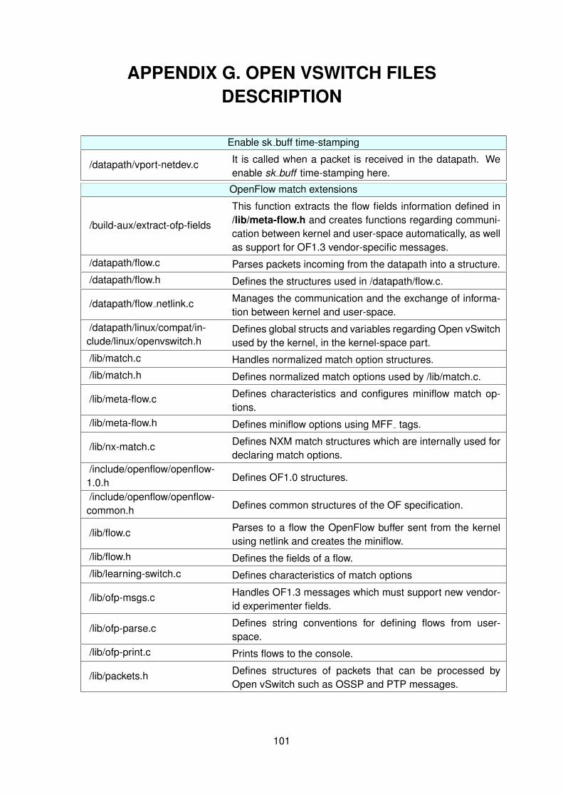
APPENDIX G. OPEN VSWITCH FILESDESCRIPTION
Enable sk buff time-stamping
/datapath/vport-netdev.c It is called when a packet is received in the datapath. Weenable sk buff time-stamping here.
OpenFlow match extensions
/build-aux/extract-ofp-fields
This function extracts the flow fields information defined in/lib/meta-flow.h and creates functions regarding communi-cation between kernel and user-space automatically, as wellas support for OF1.3 vendor-specific messages.
/datapath/flow.c Parses packets incoming from the datapath into a structure./datapath/flow.h Defines the structures used in /datapath/flow.c.
/datapath/flow netlink.c Manages the communication and the exchange of informa-tion between kernel and user-space.
/datapath/linux/compat/in-clude/linux/openvswitch.h
Defines global structs and variables regarding Open vSwitchused by the kernel, in the kernel-space part.
/lib/match.c Handles normalized match option structures./lib/match.h Defines normalized match options used by /lib/match.c.
/lib/meta-flow.c Defines characteristics and configures miniflow match op-tions.
/lib/meta-flow.h Defines miniflow options using MFF tags.
/lib/nx-match.c Defines NXM match structures which are internally used fordeclaring match options.
/include/openflow/openflow-1.0.h Defines OF1.0 structures.
/include/openflow/openflow-common.h Defines common structures of the OF specification.
/lib/flow.c Parses to a flow the OpenFlow buffer sent from the kernelusing netlink and creates the miniflow.
/lib/flow.h Defines the fields of a flow./lib/learning-switch.c Defines characteristics of match options
/lib/ofp-msgs.c Handles OF1.3 messages which must support new vendor-id experimenter fields.
/lib/ofp-parse.c Defines string conventions for defining flows from user-space.
/lib/ofp-print.c Prints flows to the console.
/lib/packets.h Defines structures of packets that can be processed byOpen vSwitch such as OSSP and PTP messages.
101

OpenFlow actions extensions
/build-aux/extract-ofp-actions
This function extracts the actions defined in /lib/ofp-actions.c and creates functions regarding communicationbetween kernel and user-space automatically, as well assupport for OF1.3 vendor-specific messages.
/datapath/actions.c Performs actions in kernel-space./datapath/flow.c Parses packets incoming from the datapath into a structure./datapath/flow.h Defines the structures used in /datapath/flow.c.
/datapath/flow netlink.cManages the communication and the exchange of informa-tion between kernel and user-space, in the kernel-spacepart
/datapath/linux/compat/in-clude/linux/openvswitch.h
Defines global structures and variables regarding OpenvSwitch used by the kernel.
/ofproto/ofproto-dpif-xlate.c Retrieves the action’s attributes to be performed when ap-plying the actions.
/include/openflow/openflow-common.h Defines common structures of the OF specification.
/lib/odp-execute.c Performs actions in user-space if required.
/lib/odp-util.c Manages the communication and the exchange of informa-tion between kernel and user-space, in the user-space part.
/lib/odp-util.h Defines structures and functions used in /lib/odp-util.c
/lib/ofp-actions.c Manages the actions and defines the functions to interactwith them.
/lib/ofp-actions.h Defines structures and functions used in /lib/ofp-actions.c
/lib/ofp-parse.c Defines string conventions for defining flows from user-space.
/lib/ofp-print.c Prints flows to the console.
/lib/packets.h Defines structures of packets that can be processed byOpen vSwitch such as OSSP and PTP messages
OpenFlow statistics extensions
/build-aux/extract-ofp-fieldsScript that takes the messages defined in /lib/ofp-msgs.hand creates functions regarding parsing of vedor-specificmessages.
/include/openflow/openflow-common.h Defines common structures of OF specification.
/ofproto/ofproto.c Handles the stats request message and builds the statis-tics reply message structure.
/vswitchd/bridge.cChecks periodically the statistics of the switch. An asyn-chronous message is sent whenever there is a change inthe FSS statistics.
/ofproto/connmgr.c Sends the asynchronous message to the controller usingthe OF channel.

OpenFlow messages extensions
/lib/ofp-msgs.c Handles OF1.3 messages which must support newvendor-id experimenter fields.
/lib/ofp-msgs.h Defines structs that are used in /lib/ofp-msgs.c./lib/ofp-print.c Prints packets to the console when debugging./lib/ofp-util.c Decodes experimenter messages./lib/ofp-util.h Defines the structs of experimenter messages.
/lib/rconn.c Defines characteristics of the new experimenter mes-sages.
/ofproto/ofproto.c Handles vendor-specific messages and takes actions onthem (e.g. send a REPLY).
Testing
/tests/ofp-print.at Testing of messages: FLOW MOD with new match op-tions or actions, new vendor-specific messages, etc.
/tests/ofproto-dpif.at Testing of the datapath packet parsing.
Table G.1: Files modified to implement proposed OpenFlow extensions.