Embed Size (px)
Citation preview
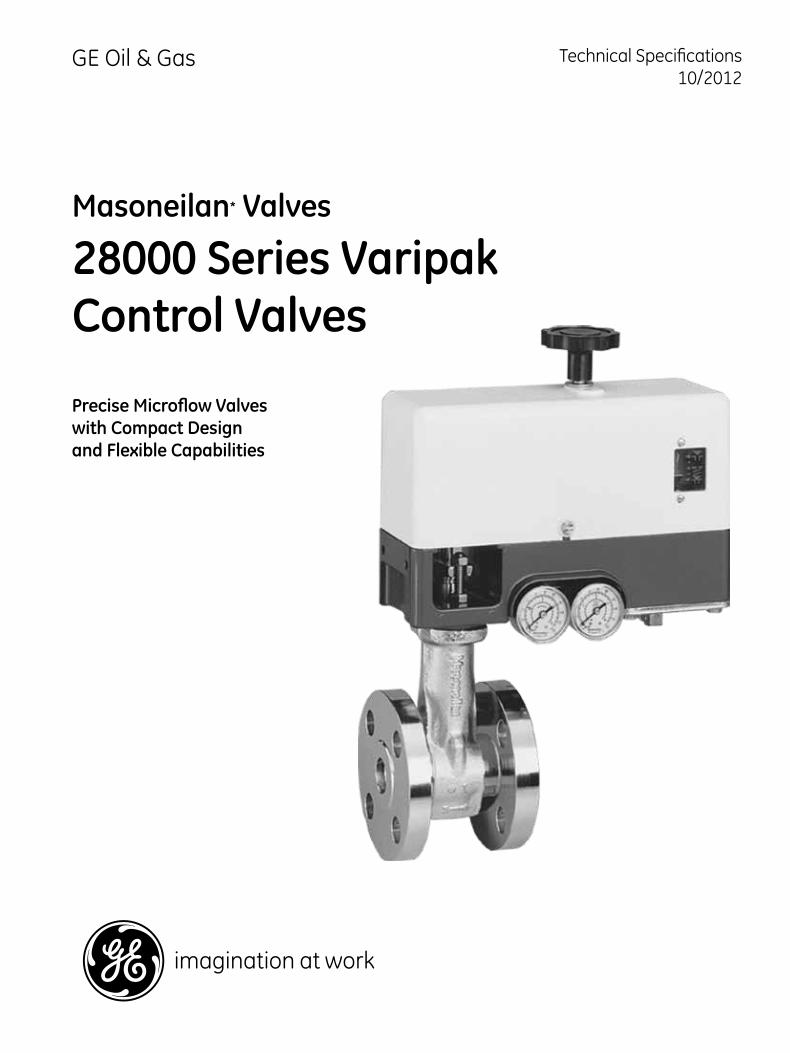
Technical Specifications10/2012
GE Oil & Gas
Masoneilan* Valves
28000 Series Varipak Control Valves
Precise Microflow Valves with Compact Design and Flexible Capabilities
2 | GE Energy
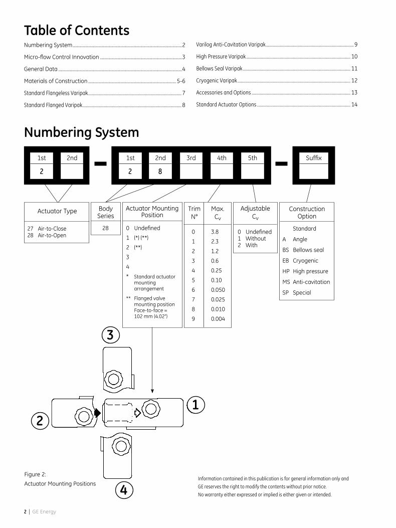
Numbering System
Table of ContentsNumbering System ............................................................................................2
Micro-flow Control Innovation .....................................................................3
General Data ........................................................................................................4
Materials of Construction .......................................................................... 5-6
Standard Flangeless Varipak ...................................................................................... 7
Standard Flanged Varipak ........................................................................................... 8
Varilog Anti-Cavitation Varipak ................................................................................. 9
High Pressure Varipak ................................................................................................ 10
Bellows Seal Varipak ................................................................................................... 11
Cryogenic Varipak ........................................................................................................ 12
Accessories and Options ........................................................................................... 13
Standard Actuator Options ...................................................................................... 14
Body Series
28
Construction Option
Standard
A Angle
BS Bellows seal
EB Cryogenic
HP High pressure
MS Anti-cavitation
SP Special
Adjustable Cv
0 Undefined1 Without2 With
1st
2
1st
2
Suffix2nd 2nd 3rd 4th 5th
Actuator Type
27 Air-to-Close28 Air-to-Open
8
Actuator Mounting Position
0 Undefined
1 (*) (**)
2 (**)
3
4
* Standard actuator mounting arrangement
** Flanged valve mounting position Face-to-face = 102 mm (4.02")
0 3.8
1 2.3
2 1.2
3 0.6
4 0.25
5 0.10
6 0.050
7 0.025
8 0.010
9 0.004
Trim N°
Max. Cv
Figure 2:
Actuator Mounting PositionsInformation contained in this publication is for general information only and
GE reserves the right to modify the contents without prior notice.
No warranty either expressed or implied is either given or intended.
2
3
1
4
28000 Series Varipak Control Valves | 3
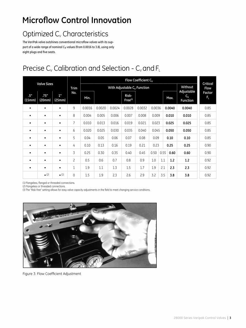
Microflow Control InnovationOptimized CV CharacteristicsThe VariPak valve outshines conventional microflow valves with its sup-
port of a wide range of nominal Cv values (from 0.0016 to 3.8), using only
eight plugs and five seats.
Precise Cv Calibration and Selection - CV and FL
Valve SizesTrim No.
Flow Coefficient CVCritical
Flow Factor
FL
With Adjustable CV Function Without Adjustable
CV Function
.5" (15mm)
.75" (20mm)
1" (25mm) Min. Risk-
Free(3) Max.
• • • 9 0.0016 0.0020 0.0024 0.0028 0.0032 0.0036 0.0040 0.0040 0.85
• • • 8 0.004 0.005 0.006 0.007 0.008 0.009 0.010 0.010 0.85
• • • 7 0.010 0.013 0.016 0.019 0.021 0.023 0.025 0.025 0.85
• • • 6 0.020 0.025 0.030 0.035 0.040 0.045 0.050 0.050 0.85
• • • 5 0.04 0.05 0.06 0.07 0.08 0.09 0.10 0.10 0.85
• • • 4 0.10 0.13 0.16 0.19 0.21 0.23 0.25 0.25 0.90
• • • 3 0.25 0.30 0.35 0.40 0.45 0.50 0.55 0.60 0.60 0.90
• • • 2 0.5 0.6 0.7 0.8 0.9 1.0 1.1 1.2 1.2 0.92
• • • 1 1.9 1.1 1.3 1.5 1.7 1.9 2.1 2.3 2.3 0.92
• • 0 1.5 1.9 2.3 2.6 2.9 3.2 3.5 3.8 3.8 0.92
(1) Flangeless, flanged or threaded connections.(2) Flangeless or threaded connections.(3) The “Risk-free” setting allows for easy valve capacity adjustments in the field to meet changing service conditions.
Figure 3: Flow Coefficient Adjustment
(2) (1)
4 | GE Energy
Body Type: globe style
angle style optional
Sizes: 1" (DN 25) standard
1/2" (DN 15) and 3/4" (DN 20) optional
Materials: Standard: type 316L St. St.
Optional: Monel®, Hastelloy® C,
Alloy 20, others
Options: Flanged valve
Anti-cavitation Varilog
High pressure
Bellows seal
Cryogenic
Angle valve
NACE version
Trim Plug type: contoured, heavy top guided
multi-staged anti-cavitation (Varilog) optional
Seat type: metal seat
CV ratio: 500/1 at max. CV
200/1 at min. CV
Flow characteristics: linear (trim No. 0 to 5)
modified linear (trim No. 6 to 9)
Flow Direction: flow-to-open
flow-to-close optional
Actuator Type: spring-opposed rolling diaphragm
Action: direct or reverse, easily performed without
additional parts
CV adjustment: optional adjustable knob/lever
Handwheel: optional top mounted
Air connection: 1/8" NPT
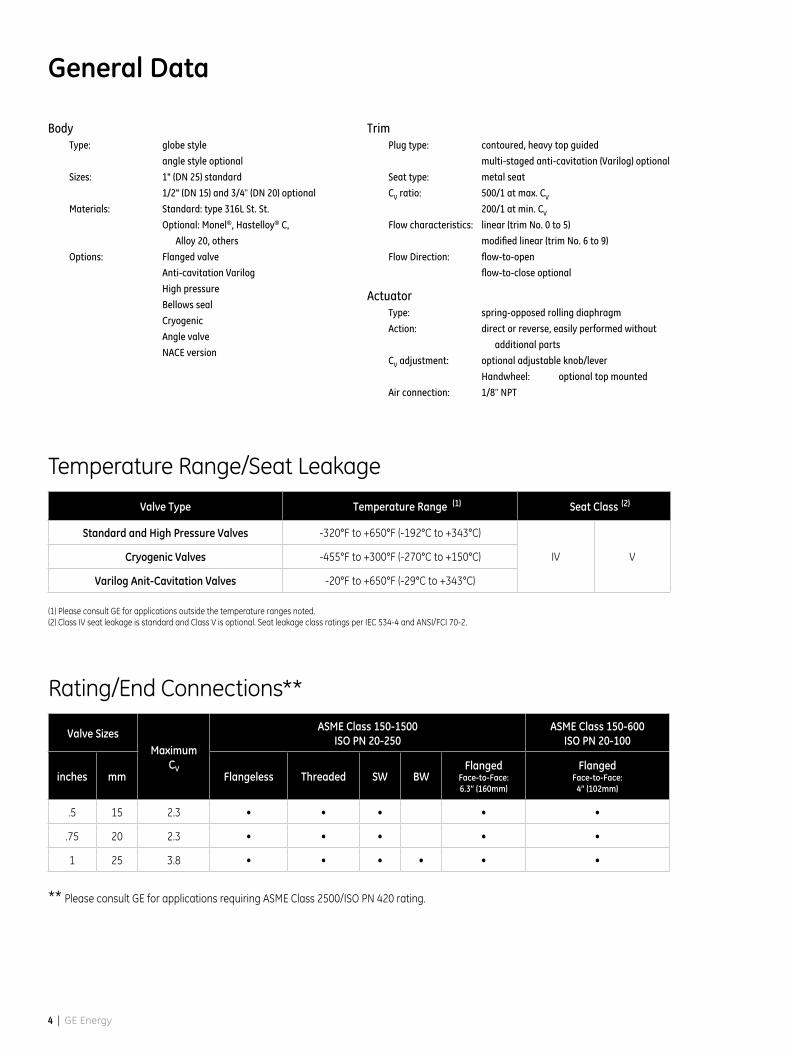
General Data
Rating/End Connections**
Valve SizesMaximum
CV
ASME Class 150-1500 ISO PN 20-250
ASME Class 150-600 ISO PN 20-100
inches mm Flangeless Threaded SW BWFlanged
Face-to-Face:6.3” (160mm)
Flanged Face-to-Face:
4” (102mm)
.5 15 2.3 • • • • •
.75 20 2.3 • • • • •
1 25 3.8 • • • • • •
** Please consult GE for applications requiring ASME Class 2500/ISO PN 420 rating.
Temperature Range/Seat Leakage
Valve Type Temperature Range Seat Class
Standard and High Pressure Valves -320°F to +650°F (-192°C to +343°C)
IV VCryogenic Valves -455°F to +300°F (-270°C to +150°C)
Varilog Anit-Cavitation Valves -20°F to +650°F (-29°C to +343°C)
(1) Please consult GE for applications outside the temperature ranges noted.(2) Class IV seat leakage is standard and Class V is optional. Seat leakage class ratings per IEC 534-4 and ANSI/FCI 70-2.
(1) (2)
28000 Series Varipak Control Valves | 5
Materials of Construction
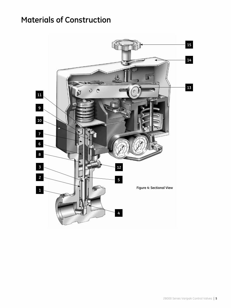
Figure 4: Sectional View1
2
4
3
5
6
7
8
9
10
11
12
13
14
15
6 | GE Energy
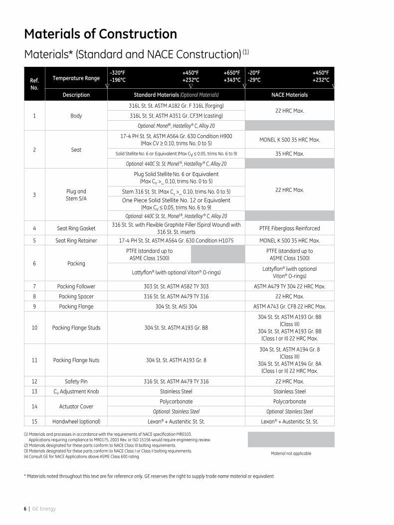
Materials* (Standard and NACE Construction) (1)
Ref. No.
Temperature Range
Description Standard Materials (Optional Materials) NACE Materials
1 Body
316L St. St. ASTM A182 Gr. F 316L (forging)22 HRC Max.
316L St. St. ASTM A351 Gr. CF3M (casting)
Optional: Monel®, Hastelloy® C, Alloy 20
2 Seat
17-4 PH St. St. ASTM A564 Gr. 630 Condition H900 (Max CV ≥ 0.10, trims No. 0 to 5)
MONEL K 500 35 HRC Max.
Solid Stellite No. 6 or Equivalent (Max CV ≤ 0.05, trims No. 6 to 9) 35 HRC Max.
Optional: 440C St. St. Monel ®, Hastelloy ® C, Alloy 20
3Plug andStem S/A
Plug Solid Stellite No. 6 or Equivalent(Max CV >_ 0.10, trims No. 0 to 5)
22 HRC Max.Stem 316 St. St. (Max Cv >_ 0.10, trims No. 0 to 5)
One Piece Solid Stellite No. 12 or Equivalent (Max CV ≤ 0.05, trims No. 6 to 9)
Optional: 440C St. St., Monel ®, Hastelloy ® C, Alloy 20
4 Seat Ring Gasket316 St. St. with Flexible Graphite Filler (Spiral Wound) with
316 St. St. insertsPTFE Fiberglass Reinforced
5 Seat Ring Retainer 17-4 PH St. St. ASTM A564 Gr. 630 Condition H1075 MONEL K 500 35 HRC Max.
6 Packing
PTFE (standard up toASME Class 1500)
PTFE (standard up toASME Class 1500)
Lattyflon® (with optional Viton® O-rings)Lattyflon® (with optional
Viton® O-rings)
7 Packing Follower 303 St. St. ASTM A582 TY 303 ASTM A479 TY 304 22 HRC Max.
8 Packing Spacer 316 St. St. ASTM A479 TY 316 22 HRC Max.
9 Packing Flange 304 St. St. AISI 304 ASTM A743 Gr. CF8 22 HRC Max.
10 Packing Flange Studs 304 St. St. ASTM A193 Gr. B8
304 St. St. ASTM A193 Gr. B8(Class III)
304 St. St. ASTM A193 Gr. B8(Class I or II) 22 HRC Max.
11 Packing Flange Nuts 304 St. St. ASTM A193 Gr. 8
304 St. St. ASTM A194 Gr. 8(Class III)
304 St. St. ASTM A194 Gr. 8A(Class I or II) 22 HRC Max.
12 Safety Pin 316 St. St. ASTM A479 TY 316 22 HRC Max.
13 CV Adjustment Knob Stainless Steel Stainless Steel
14 Actuator CoverPolycarbonate Polycarbonate
Optional: Stainless Steel Optional: Stainless Steel
15 Handwheel (optional) Lexan® + Austenitic St. St. Lexan® + Austenitic St. St.
(1) Materials and processes in accordance with the requirements of NACE specification MR0103. Applications requiring compliance to MR0175, 2003 Rev. or ISO 15156 would require engineering review.(2) Materials designated for these parts conform to NACE Class III bolting requirements.(3) Materials designated for these parts conform to NACE Class I or Class II bolting requirements.(4) Consult GE for NACE Applications above ASME Class 600 rating.
Material not applicable
Materials of Construction
-320°F -196°C
+450°F +232°C
+650°F +343°C
-20°F -29°C
+450°F +232°C
* Materials noted throughout this text are for reference only. GE reserves the right to supply trade name material or equivalent
∇ ∇ ∇ ∇
28000 Series Varipak Control Valves | 7
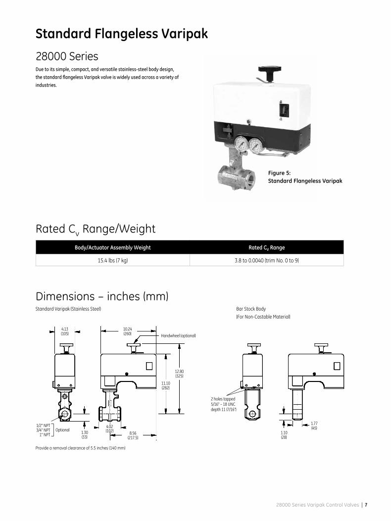
Standard Flangeless Varipak
Figure 5: Standard Flangeless Varipak
28000 SeriesDue to its simple, compact, and versatile stainless-steel body design,
the standard flangeless Varipak valve is widely used across a variety of
industries.
Body/Actuator Assembly Weight Rated CV Range
15.4 lbs (7 kg) 3.8 to 0.0040 (trim No. 0 to 9)
Provide a removal clearance of 5.5 inches (140 mm)
Optional1/2" NPT 3/4" NPT
1" NPT
10.24 (260)
4.13 (105) Handwheel (optional)
11.10 (282)
12.80 (325)
1.30 (33)
8.56 (217.5)
4.02 (102)
2 holes tapped 5/16" – 18 UNC depth 11 (7/16")
1.10 (28)
1.77 (45)
Rated Cv Range/Weight
Dimensions – inches (mm)Standard Varipak (Stainless Steel) Bar Stock Body
(For Non-Castable Material)
8 | GE Energy
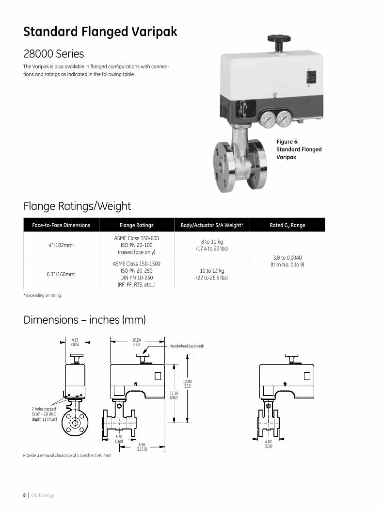
Standard Flanged Varipak
Figure 6: Standard Flanged Varipak
28000 SeriesThe Varipak is also available in flanged configurations with connec-
tions and ratings as indicated in the following table.
Face-to-Face Dimensions Flange Ratings Body/Actuator S/A Weight* Rated CV Range
4" (102mm)ASME Class 150-600
ISO PN 20-100(raised face only)
8 to 10 kg(17.4 to 22 lbs)
3.8 to 0.0040(trim No. 0 to 9)
6.3" (160mm)
ASME Class 150-1500ISO PN 20-250DIN PN 10-250
(RF, FF, RTS, etc...)
10 to 12 kg(22 to 26.5 lbs)
* depending on rating.
Dimensions – inches (mm)
Provide a removal clearance of 5.5 inches (140 mm)
10.24 (260)
4.13 (105) Handwheel (optional)
11.10 (282)
12.80 (325)
8.56 (217.5)
6.30 (160) 4.02
(102)
2 holes tapped 5/16" – 18 UNC depth 11 (7/16")
Flange Ratings/Weight
28000 Series Varipak Control Valves | 9
Dimensions – inches (mm)Standard Varipak (Stainless Steel) Bar Stock Body
(For Non-Castable Material)
Provide a removal clearance of 5.5 inches (140 mm)
Optional1/2" NPT 3/4" NPT
1" NPT
10.24 (260)
4.13 (105) Handwheel (optional)
11.10 (282)
12.80 (325)
1.30 (33)
8.56 (217.5)
4.02 (102)
2 holes tapped 5/16" – 18 UNC depth 11 (7/16")
1.10 (28)
1.77 (45)
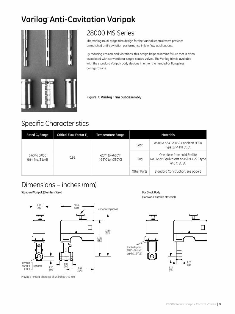
Rated CV Range Critical Flow Factor FL Temperature Range Materials
0.60 to 0.050(trim No. 3 to 6)
0.98-20°F to +660°F
(-29°C to +350°C)
SeatASTM A 564 Gr. 630 Condition H900
Type 17-4 PH St. St.
PlugOne piece from solid Stellite
No. 12 or Equivalent or ASTM A 276 type 440 C St. St.
Other Parts Standard Construction: see page 6
Varilog* Anti-Cavitation Varipak
28000 MS SeriesThe Varilog multi-stage trim design for the Varipak control valve provides
unmatched anti-cavitation performance in low flow applications.
By reducing erosion and vibrations, this design helps minimize failure that is often
associated with conventional single-seated valves. The Varilog trim is available
with the standard Varipak body designs in either the flanged or flangeless
configurations.
Figure 7: Varilog Trim Subassembly
Specific Characteristics
10 | GE Energy
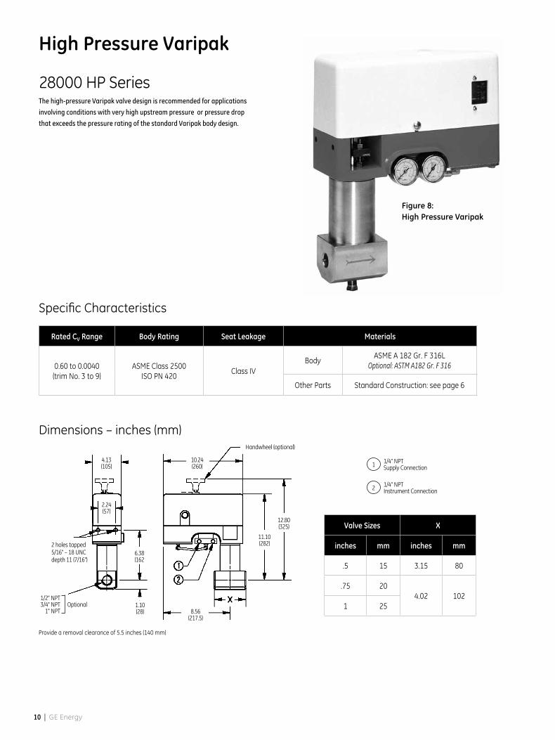
High Pressure Varipak
Figure 8: High Pressure Varipak
28000 HP SeriesThe high-pressure Varipak valve design is recommended for applications
involving conditions with very high upstream pressure or pressure drop
that exceeds the pressure rating of the standard Varipak body design.
Dimensions – inches (mm)
Provide a removal clearance of 5.5 inches (140 mm)
10.24 (260)
4.13 (105)
Handwheel (optional)
11.10 (282)
12.80 (325)
8.56 (217.5)
1.10 (28)
6.38 (162
2 holes tapped 5/16" – 18 UNC depth 11 (7/16")
Rated CV Range Body Rating Seat Leakage Materials
0.60 to 0.0040 (trim No. 3 to 9)
ASME Class 2500 ISO PN 420
Class IVBody
ASME A 182 Gr. F 316LOptional: ASTM A182 Gr. F 316
Other Parts Standard Construction: see page 6
2.24 (57)
Optional1/2" NPT 3/4" NPT
1" NPT
Valve Sizes X
inches mm inches mm
.5 15 3.15 80
.75 204.02 102
1 25
1 1/4" NPTSupply Connection
2 1/4" NPTInstrument Connection
Specific Characteristics
28000 Series Varipak Control Valves | 11
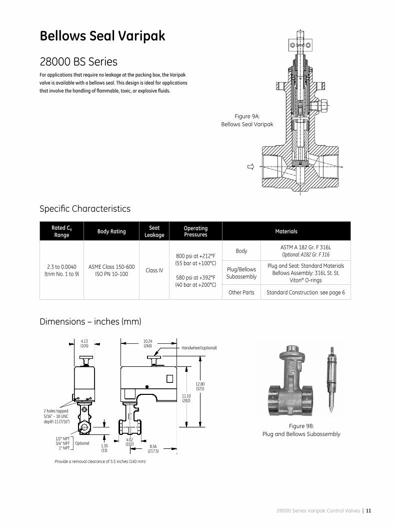
Bellows Seal Varipak
Figure 9A: Bellows Seal Varipak
28000 BS SeriesFor applications that require no leakage at the packing box, the Varipak
valve is available with a bellows seal. This design is ideal for applications
that involve the handling of flammable, toxic, or explosive fluids.
Dimensions – inches (mm)
2 holes tapped 5/16" – 18 UNC depth 11 (7/16")
Rated CV Range Body Rating Seat
LeakageOperating Pressures Materials
2.3 to 0.0040(trim No. 1 to 9)
ASME Class 150-600ISO PN 10-100
Class IV
800 psi at +212°F(55 bar at +100°C)
580 psi at +392°F(40 bar at +200°C)
BodyASTM A 182 Gr. F 316LOptional: A182 Gr. F 316
Plug/BellowsSubassembly
Plug and Seat: Standard MaterialsBellows Assembly: 316L St. St.
Viton® O-rings
Other Parts Standard Construction: see page 6
Figure 9B: Plug and Bellows Subassembly
Provide a removal clearance of 5.5 inches (140 mm)
Optional1/2" NPT 3/4" NPT
1" NPT
10.24 (260)
4.13 (105) Handwheel (optional)
11.10 (282)
12.80 (325)
1.30 (33)
8.56 (217.5)
4.02 (102)
Specific Characteristics
12 | GE Energy
Cryogenic Varipak
28000 EB SeriesSimplified maintenance
This Varipak control valve design meets the requirements of cryogenic process-
es that require thermal insulation. An insulating interface sets up between the
valve body (cold zone) and the body extension located in the higher temperature
area (warm zone). The valve body assembly and its thermal extension are po-
sitioned inside the cold box, and the plug can easily be removed and inspected
without disturbing the valve body. This eliminates the need for any preliminary,
complicated dismounting, and more importantly, prevents any interference
with the cold box.
Body
Manufactured from a material suitable for low temperatures, the valve body
maintains ductility in service. It can be conveniently mounted to suit specific
piping needs, as long as the angle between the valve axis and vertical does not
exceed 60°.
The bonnet is located away from the cryogenic fluid, which means that the body
gasket is not inside the cold zone. This design prevents any leakage
of the cryogen into the insulated zone.
Body extension
To reduce the inflow of head by conduction, thin-walled metal tubes are used
for the body extension and coupling sleeve. In addition, the annular space is
reduced to exclude convection currents.
Plug
The design of the plug allows the working parts to be accurately centered in
relation to the seat and provides a uniform temperature zone for the guiding.
Dimensions – inches (mm)
Rated CV Range
Temperature Range
Body Rating
Seat Leakage Materials
3.8 to 0.10(trim No. 0 to 5)
-455°F to +300°F(-270°C to + 150°C)
ASME Class 150-600 ISO PN 20-100
excepted trim No. 0:
ASME Class 150-300ISO PN 20-50
Class IV
Body and Extension
ASTM A 182 Gr. F 316L
Plug/Stem Standard Material
SeatTrim No. 0: Standard Material
Trim No. 1 to 5: ASTM A 564 Gr. 630Condition H900 Type 17-4 PH. St. St.
O-ring SeatGasket
PTFE
Other Parts Standard Construction: see page 6
Specific Characteristics
Provide a removal clearance of 5.5 inches (140 mm)
Figure 10: Cryogenic Varipak
2 holes tapped 5/16" – 18 UNC depth 11 (7/16")
10.24 (260)
4.13 (105)
Handwheel (optional)
20.43 (519)
22.13 (562)
1.30 (33)4.02 (102)
8.56 (217.5)
2.24 (57)
15.71 (399)
1 1/4" NPTSupply Connection
2 1/4" NPTInstrument Connection
28000 Series Varipak Control Valves | 13
Accessories and Options
Pneumatic Positioner (Model 7700P)Type
pneumatic, force balance
Mounting
built-in bracket in actuator
Action
direct: increasing instrument signal
increases air output
Characteristics
linear
Instrument signal
3 to 15, 6 to 30 or 3 to 27 psi
200 to 1000, 400 to 2050 or
(200 to 1850 mbar)
3 to 9, and 9 to 15 psi
(200 to 600 and 600 to 1000 mbar)
split range
Connections
1/4" NPT instrument and supply –
1/8" NPT output
Average air consumption
0.15 scfm at 30 psi supply
(0.26 Nm3/h at 2.1 bar supply)
Max. air output
4.20 scfm (7 Nm3/h)
Supply pressure effect
0.05 percent of full stroke variation per
psi supply pressure change
(0.07 percent per 100 mbar)
Open loop gain
70
Linearity
± 0.5 percent
Sensitivity
0.1 percent
Repeatability
0.1 percent
Full stroke time
less than one second
Weight
3.3 lbs (1.5 kg)
Other Accessories
Proximity sensors and limit switches
Digital positioners – HART® and
Fieldbus Foundation
Handwheel, airsets and solenoid valves
Electropneumatic Positioner (Model 7700E)Type
electropneumatic, force balance
Mounting
compact, without external linkage
to the actuator (see Fig. 15)
Action
direct: increasing instrument signal
increases air output
Characteristics
linear
Instrument signal
4-20 mA
Air Connections
1/4" NPT supply – 1/8" NPT output
Average air consumption
0.24 scfm (0.4 Nm3/h)
Electrical connections
1/2" NPT or M20
Weight
7.7 lbs (3.5 kg)
Hazardous Location Protection
ATEX Approvals (94/9/EC Directive)
Explosionproof
No. SIRA 02 ATEX 1274
Intrinsic Safety
No. SIRA 02 ATEX 2277 X
FM (Factory Mutual) Approvals
Explosionproof
Intrinsic Safety
Non-incendive and
Dust-ignitionproof
CSA Approvals
(Canadian Standards Association)
Explosionproof
Intrinsic Safety
Non-incendive
Figure 11: Model 7700P Pneumatic Positioner
Figure 12: Model 7700E Electropneumatic Positioner
14 | GE Energy
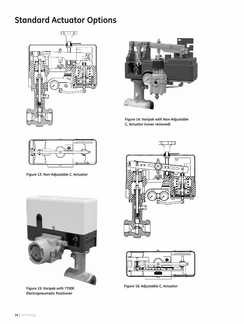
Standard Actuator Options
Figure 15: Varipak with 7700E Electropneumatic Positioner
Figure 14: Varipak with Non-Adjustable CV Actuator (cover removed)
Figure 13: Non-Adjustable CV Actuator
Figure 16: Adjustable CV Actuator
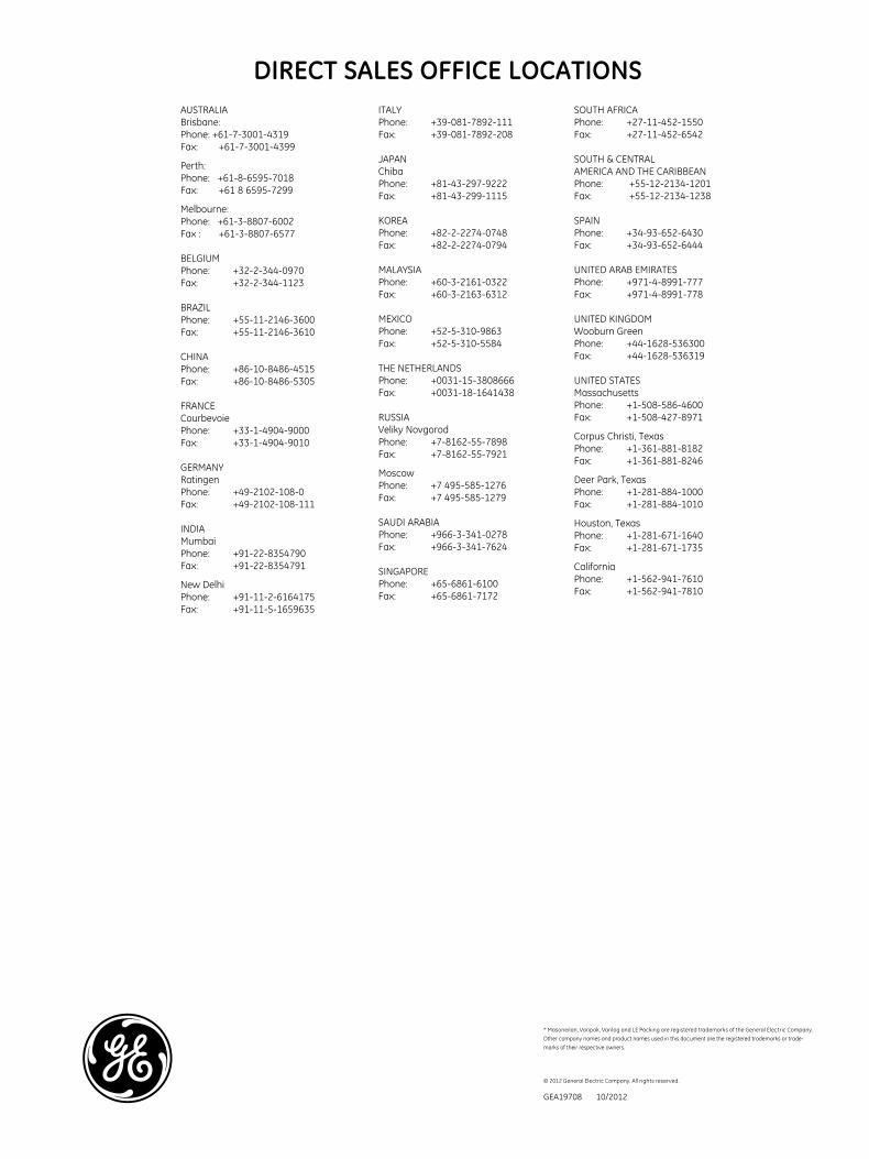
DIRECT SALES OFFICE LOCATIONS
GEA19708 10/2012
© 2012 General Electric Company. All rights reserved.
* Masoneilan, Varipak, Varilog and LE Packing are registered trademarks of the General Electric Company.
Other company names and product names used in this document are the registered trademarks or trade-
marks of their respective owners.
AUSTRALIABrisbane:Phone: +61-7-3001-4319Fax: +61-7-3001-4399
Perth:Phone: +61-8-6595-7018Fax: +61 8 6595-7299
Melbourne:Phone: +61-3-8807-6002Fax : +61-3-8807-6577
BELGIUMPhone: +32-2-344-0970Fax: +32-2-344-1123
BRAZILPhone: +55-11-2146-3600Fax: +55-11-2146-3610
CHINAPhone: +86-10-8486-4515Fax: +86-10-8486-5305
FRANCECourbevoiePhone: +33-1-4904-9000Fax: +33-1-4904-9010
GERMANYRatingenPhone: +49-2102-108-0Fax: +49-2102-108-111
INDIAMumbaiPhone: +91-22-8354790Fax: +91-22-8354791
New DelhiPhone: +91-11-2-6164175Fax: +91-11-5-1659635
ITALYPhone: +39-081-7892-111Fax: +39-081-7892-208
JAPANChiba Phone: +81-43-297-9222Fax: +81-43-299-1115
KOREAPhone: +82-2-2274-0748Fax: +82-2-2274-0794
MALAYSIAPhone: +60-3-2161-0322Fax: +60-3-2163-6312
MEXICOPhone: +52-5-310-9863Fax: +52-5-310-5584
THE NETHERLANDSPhone: +0031-15-3808666Fax: +0031-18-1641438
RUSSIAVeliky NovgorodPhone: +7-8162-55-7898Fax: +7-8162-55-7921
MoscowPhone: +7 495-585-1276Fax: +7 495-585-1279
SAUDI ARABIAPhone: +966-3-341-0278Fax: +966-3-341-7624
SINGAPOREPhone: +65-6861-6100Fax: +65-6861-7172
SOUTH AFRICAPhone: +27-11-452-1550Fax: +27-11-452-6542
SOUTH & CENTRAL AMERICA AND THE CARIBBEANPhone: +55-12-2134-1201Fax: +55-12-2134-1238
SPAINPhone: +34-93-652-6430Fax: +34-93-652-6444
UNITED ARAB EMIRATESPhone: +971-4-8991-777Fax: +971-4-8991-778
UNITED KINGDOMWooburn GreenPhone: +44-1628-536300Fax: +44-1628-536319
UNITED STATESMassachusettsPhone: +1-508-586-4600Fax: +1-508-427-8971
Corpus Christi, Texas Phone: +1-361-881-8182Fax: +1-361-881-8246
Deer Park, TexasPhone: +1-281-884-1000Fax: +1-281-884-1010
Houston, TexasPhone: +1-281-671-1640Fax: +1-281-671-1735
CaliforniaPhone: +1-562-941-7610Fax: +1-562-941-7810