Embed Size (px)
Citation preview

Marley DWV Technical Design Manual.
0800 MARLEY


PRODUCT DESCRIPTION
D W V T E C H N I C A L D E S I G N M A N U A L3
INTRODUCTION
Introduction
1
This is the second edition of the Marley New Zealand Ltd DWV Installation and Technical Catalogue. It provides a practical guide to the design, installation and operation of unplasticised polyvinyl chloride (PVC) pipelines used for the conveyance of foul water.
Its revision has been prompted by the amalgamation of the New Zealand and Australian Standards, which has resulted in two key documents; AS/NZS 1260 PVC pipes and fittings for drain waste and vent, AS/NZS 3500.2.2 Sanitary plumbing and drainage - acceptable solutions Installation method.
Since the introduction of PVC Pipes into the New Zealand plumbing and drainage market over three decades ago, PVC DWV pipe has become an integral link in foul water drainage systems in this country.
PVC pipe has proven to be the most competitive in cost, with ease of installation combined with its physical characteristics of corrosion resistance and high strength to weight ratio, justifying its selection as the prime material option for drainage networks.
Over the last fifteen years extensive research and development has resulted in continual improvements in processing techniques, quality control and behavioural understanding of the material. Users of PVC pipes and fittings manufactured to AS/NZS 1260 are assured of consistently high quality products which, in addition to their traditional characteristics, now have enhanced toughness.
This second edition reflects the changes in specifications and materials which have taken place since the first edition was produced.
We trust you will find this design manual informative and a key point of reference in conducting any aspect of design, installation or sale.

SECT
ION
1 :
PVC
PIP
E PR
OPER
TIES 1. PVC Pipe Properties
D W V T E C H N I C A L D E S I G N M A N U A L2
}AS 1530 Early Fire Hazard
MATERIAL PROPERTIES
1.1 Mechanical Properties of PVC @ 20oC
Density 1.42 - 1.48 Water Absorption 0.12% in 24 hours @ 23o
Hardness (Shore D) 80 Impact 20oC (Charpy 250µm notch) 20 KJ/m2 (PVC) Impact 0o (Charpy 250µm notch) 8 KJ/m2 (PVC) Coefficient of Friction (PVC to PVC) 0.4
Ultimate Tensile Strength 52 MPa Elongation at Break 50 - 80% Short Term Rupture 44 MPa Long Term Creep 28 MPa
Compressive Strength 65 MPa Long Term Creep Modulus 0.9 - 1.2 GPa Elastic Tensile Modulus 3.0 - 3.3 GPa Elastic Flexural Modulus 2.7 - 3.0 GPa
Shear Modulus 1.0 GPa Bulk Modulus 4.7 GPa Poison Ratio 0.4
1.2 Electrical Properties
Dielectric Strength 14-20 KV/mm Volume Resistivity 2 x 10¹⁴ Ω.m Surface Resistivity 1013 - 1014 Ω Dielectric Constant 50Hz (106 Hz) 3.9 (3.3) Power Factor 50Hz (106 Hz) 0.01 (0.02)
Voltage Breakdown 2000 volts/mm
Insulating Strength > 500 MΩ
1.3 Thermal Properties
Softening Point 79-84oC Maximum Continuous Service Temp 60°C Coefficient of Thermal Expansion 8 x 10⁻⁵
Thermal Conductivity 0.16 W/[m.oC] Specific Heat 1000 J/[Kg. oC] Thermal Diffusivity 1.1 x 10⁻⁷ m2/S
1.4 Flammability Characteristics
Flammability (Oxygen Index) 45% Ignitability Index 9 - 10 (/20) Smoke Produced Index 4 - 6 (/10) Heat Evolved Index 0 Spread of Flame Index *
* PVC is self extinguishing. It does not support combustion when the source of ignition is removed.

SECTION 1 : PVC PIPE PROPERTIES
1. PVC Pipe Properties
D W V T E C H N I C A L D E S I G N M A N U A L3
PIPE PROPERTIES
1.5 Service Temperature
All Marley drains, wastes and vents are suitable for the continuous discharge of liquids at temperatures up to 60°C for vertical pipes and grade pipes, as well as intermittent discharges of liquids up to 90°C where the duration of the discharge does not exceed 90 seconds.
For discharge of liquids at temperatures above 60°C but not exceeding 75°C graded pipes and fittings must be continuously supported. PVC must not be used for continuous discharge of liquids at temperatures exceeding 75°C.
1.6 Durability
Marley DWV waste and vent pipes and fittings fully comply with G13/AS2 Table 3 and E1/AS1 Table 1.
PVC has proven durability over the last 50 years. The Marley system alone has been successfully used in New Zealand for 30 years. When installed and used in accordance with the installation instruction (see section four). Marley waste & vent pipes will have durability in excess of:
• 50 years for systems with difficult access (eg under buildings)• 15 years for systems with a moderate ease of access, but difficult to replace (eg typical drainage system laid adjacent to a building foundation).
Marley DWV Sanitary drains will have a life expectancy in excess of 100 years, when installed, bedded and used in accordance with the installation and operation instructions.
1.7 Weatherability
All Marley DWV pipes and fittings have 1.5 PHR of Titanium Dioxide to provide long term UV protection when installed above ground. The ultimate strength of PVC does not alter markedly with age. With prolonged exposure to UV light, a loss of impact strength can be expected, although changes are minor and should not reduce the system’s long-term performance.
For above ground systems, extra UV light protection can be added by simply applying a coat of 100% acrylic paint. Pipes should be washed with detergent and water to remove any grease and dirt. If priming is required, use an alkyd-based general purpose primer before the acrylic finishing coats.
1.8 Impact Strength
Impact tests of all DWV Pipe Systems are carried out to AS/NZS 1260 and AS/NZS 1462.3.
At low temperatures the impact strength of standard PVC will be reduced, therefore care needs to be taken when cutting, handling or backfilling in cold conditions.
1.9 Biological Attack
The performance of PVC pipe in severe environments has been studied since its introduction in the 1930s. These studies have found that PVC pipe will not deteriorate or break down under biological attack, as PVC does not serve as a nutrient for micro or macro organisms. Investigations have failed to discover a single case in which buried PVC pipe products have suffered degradation or deterioration due to biological attack.
Once PVC pipe has been installed underground in normal water and sewer systems, it is not susceptible to the normal processes of deterioration found in nature. It does not slime as readily as many other materials and will usually require less maintenance (blockage clearance).
SECT
ION
1 :
PVC
PIP
E PR
OPER
TIES 1. PVC Pipe Properties
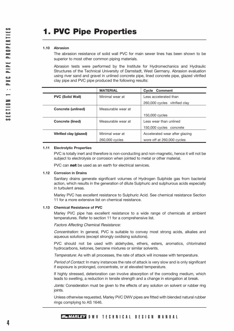
1.10 Abrasion
The abrasion resistance of solid wall PVC for main sewer lines has been shown to be superior to most other common piping materials.
Abrasion tests were performed by the Institute for Hydromechanics and Hydraulic Structures of the Technical University of Damstadt, West Germany. Abrasion evaluation using river sand and gravel in unlined concrete pipe, lined concrete pipe, glazed vitrified clay pipe and PVC pipe produced the following results:
MATERIAL Cycle Comment
PVC (Solid Wall) Minimal wear at Less accelerated than
260,000 cycles vitrified clay
Concrete (unlined) Measurable wear at
150,000 cycles
Concrete (lined) Measurable wear at Less wear than unlined
150,000 cycles concrete
Vitrified clay (glazed) Minimal wear at Accelerated wear after glazing
260,000 cycles wore off at 260,000 cycles
1.11 Electrolytic Properties
PVC is totally inert and therefore is non-conducting and non-magnetic, hence it will not be subject to electrolysis or corrosion when jointed to metal or other material.
PVC can not be used as an earth for electrical services.
1.12 Corrosion in Drains
Sanitary drains generate significant volumes of Hydrogen Sulphide gas from bacterial action, which results in the generation of dilute Sulphuric and sulphurous acids especially in turbulent areas.
Marley PVC has excellent resistance to Sulphuric Acid. See chemical resistance Section 11 for a more extensive list on chemical resistance.
1.13 Chemical Resistance of PVC
Marley PVC pipe has excellent resistance to a wide range of chemicals at ambient temperatures. Refer to section 11 for a comprehensive list.
Factors Affecting Chemical Resistance:
Concentration: In general, PVC is suitable to convey most strong acids, alkalies and aqueous solutions (except strongly oxidising solutions).
PVC should not be used with aldehydes, ethers, esters, aromatics, chlorinated hydrocarbons, ketones, benzene mixtures or similar solvents.
Temperature: As with all processes, the rate of attack will increase with temperature.
Period of Contact: In many instances the rate of attack is very slow and is only significant if exposure is prolonged, concentrate, or at elevated temperature.
If highly stressed, deterioration can involve absorption of the corroding medium, which leads to swelling, a reduction in tensile strength and a change in elongation at break.
Joints: Consideration must be given to the effects of any solution on solvent or rubber ring joints.
Unless otherwise requested, Marley PVC DWV pipes are fitted with blended natural rubber rings complying to AS 1646.
D W V T E C H N I C A L D E S I G N M A N U A L4

SECTION 2 : PRODUCT DATA
2. Product Data
5D W V T E C H N I C A L D E S I G N M A N U A L
2.1 Joint Systems
Rubber ring jointing (RRJ) and solvent socket jointing (SOE) are the standard systems provided. Rubber ring jointing is the preferred method for below ground installations.
Solvent welded joints are typically used in smaller diameter pipes, and are available in sizes up to and including DN175. Rubber Ring Joints (RRJ) are available in sizes 100DN and greater. See section 3.
2.2 Markings
All Marley DWV pipes are printed with the following details at approximately metre intervals.
2.3 Types of Pipes
Marley currently manufactures three different types of pipe for drainage applications.
2.3.1 Marley Optim - This is a solid wall PVC pipe produced from selected materials to give an extra rigid durable pipe system.
2.3.2 Marley Impact -This solid wall mPVC is produced to provide extreme ductility in areas where the pipe could be subjected to adverse mechanical treatment.
Class SN20 is pressure rated to PN9 and may be used for pumping and rising sewer mains subject to normal design and installation requirements.
Other stiffness classes SN4, SN8 and SN16 are available in this product to suit specific installation requirements.
This pipe has excellent cold temperature performance.
2.3.3 Marley Optim2000SC - Is a composite sandwich wall from selected rigid PVC designed for ease of handling, but with excellent durability and wall thicknesses to give the same high performance as Marley Optim.
2.4 Classes Stiffness Performance Rating
Marley PVC DWV pipe system is manufactured to different pipe stiffness classes to suit the performance requirements of the installation. These are designated by the Nominal Stiffness (SN) in N/m/m as determined according to the crush resistance test of AS1462.22.
SN4 and SN6 - These pipes are considered suitable for all domestic plumbing and drainage for domestic and residential housings in 100 and 150mm sizing.
SN8 and SN10 - Is suitable for general drainage and commercial installation where higher pipe stiffness is required to provide minimum deflection of installed pipes, due to imposed loads from backfill or to assist with poor bedding practices and materials.
SN16 and Greater-Territorial Authority - This pipe is designed to meet the requirements of the Territorial Authority where very high long term stiffness is required to provide minimal ovality due to high imposed traffic loads or very high coverage depths and to accommodate varying bedding performance to give long term asset cost performance in excess of 100 years for territorial authority services.
2. Product Data
2.5 Production Quality Control and Quality Assurance
2.5.1 The manufacture of PVC pipe involves continuous processing of the polymer, which necessitates the strict and accurate control of both materials and plant to meet the required standards. Marley has adopted individual internal procedures which embrace increasingly comprehensive testing by the process technician on each line and quick response laboratory testing programmes, with trained production personnel operating quality manufacturing systems.
2.5.2 These quality control procedures normally include:
• Quality testing of raw materials.• Checks on the uniformity and consistency of the powder blend input.• Control of processing parameters in terms of temperature, pressure, flow rates, haul-off
speed and energy input.• Visual inspection of the pipes to check general appearance, dimensional compliance,
including wall thickness, diameter, length, socket jointing ends and sealing rings.• Production tests are carried out at regular intervals from each extrusion line, usually one
sample every 2 hours. These laboratory tests are fully recorded and identify the pipe by time and date so they can be related to pipe in the field.
2.5.3 Quality control tests and procedures are performed by trained personnel in accord-ance with ISO 9002 Quality Management System in our International Accreditation New Zealand Resistered Laboratory (Reg No 92).
• Dimensional Measurement of external diameter and pipe wall thickness (AS/NZS 1462.1).
• Deformation Tests to check the pipe stiffness (AS/NZS 1462.22)
• Impact Tests to check the general toughness of the pipe and its ability to withstand the normal shocks which may be expected during handling, transportation and installation during normal use. (AS/NZ 1462.3).
• Heat Reversion Tests designed to show up any excessive built-in (residual) stresses in the pipe and fittings (AS/NZ 1462.4) (AS/NZ 1462.11).
• Production Type Tests. In addition to “production monitoring” tests, there are a number of important longer term “Type Tests” which are required to demonstrate the pipes long term performance. These tests are reviewed at less frequent intervals and are carried out whenever there is any change in parameters such as formulation, size, classification and processing technique.
2.6 Standards
Marley’s PVC DWV range of pipe systems are manufactured to AS/NZS 1260 “PVC pipes and fittings for drain waste and vent applications”.
This manual is designed to assist in the use of the Marley DWV range of pipes and fittings in complying with Building Industry Code G13 and B2 and Installation and Design Practices AS/NZS 3500.2.2.individual back vents and minimising waste pipe and external gully traps.
PROD
UCT
DESC
RIPT
ION
D W V T E C H N I C A L D E S I G N M A N U A L6 7

STANDARDS: AS/NZS 1260 : 1999 PIPE STIFFNESS NOMINAL MEAN OD SOCKET OD INSERTION RECOMMEND CLASS. CLASS. SIZE DN mm mm LENGTH USAGE AS/NZS 1462.22 mm N/m/m
OPTIM 32 36.2 - 36.5 - - DR / COM - 40 42.8 - 43.1 - - - 50 55.7 - 56.0 - - - 65 68.7 - 69.1 - - 80 82.3 - 82.7 - - OPTIM SN6 100 110 - 110.4 128.5 70 DR OPTIM SN10 100 110 - 110.4 128.5 70 DR / COM OPTIM SN16 100 110 - 110.4 128.5 70 DR / COM / TA
IMPACT SN6 100 110 - 110.4 128.5 70 DR IMPACT SN10 100 110 - 110.4 128.5 70 DR / COM IMPACT SN16 100 110 - 110.4 128.5 70 DR / COM / TA IMPACT PN 9 SN20 100 110 - 110.4 128.5 70 DR / COM / TA / TAC OPTIM SN4 150 160 - 160.5 196.0 115 DR OPTIM SN8 150 160 - 160.5 196.0 115 DR / COM OPTIM SN16 150 160 - 160.5 196.0 115 DR / COM / TA IMPACT SN4 150 160 - 160.5 196.0 115 DR IMPACT SN8 150 160 - 160.5 196.0 115 DR / COM IMPACT SN16 150 160 - 160.5 196.0 115 DR / COM / TA IMPACT PN 9 SN20C 150 160 - 160.5 196.0 115 DR / COM / TA / TAC OPTIM 2000 SC SN16 150 160 - 160.5 196.0 115 DR / COM / TA OPTIM 2000 SC SN20C 150 160 - 160.5 196.0 115 DR / COM / TA / TAC OPTIM SN4 175 200 - 200.6 238.0 155 DR OPTIM SN8 175 200 - 200.6 238.0 155 DR / COM OPTIM SN16 175 200 - 200.6 238.0 155 DR / COM / TA IMPACT SN4 175 200 - 200.6 238.0 155 DR IMPACT SN8 175 200 - 200.6 238.0 155 DR / COM IMPACT SN16 175 200 - 200.6 238.0 155 DR / COM / TA IMPACT PN 9 SN20C 175 200 - 200.6 238.0 155 DR / COM / TA / TAC OPTIM SN4 225 250 - 250.7 296.0 174 DR OPTIM SN8 225 250 - 250.7 296.0 174 DR / COM OPTIM SN16 225 250 - 250.7 296.0 174 DR / COM / TA IMPACT SN4 225 250 - 250.7 296.0 174 DR IMPACT SN8 225 250 - 250.7 296.0 174 DR / COM IMPACT SN16 225 250 - 250.7 296.0 174 DR / COM / TA IMPACT PN 9 SN20C 225 250 - 250.7 296.0 174 DR / COM / TA / TAC OPTIM SN4 300 315 - 315.9 375.0 195 DR OPTIM SN8 300 315 - 315.9 375.0 195 DR / COM OPTIM SN16 300 315 - 315.9 375.0 195 DR / COM / TA IMPACT SN4 300 315 - 315.9 375.0 195 DR IMPACT SN8 300 315 - 315.9 375.0 195 DR / COM IMPACT SN16 300 315 - 315.9 375.0 195 DR / COM / TA OPTIM SN4 375 400 - 401.0 470.0 255 DR OPTIM SN8 375 400 - 401.0 470.0 255 DR / COM OPTIM SN16 375 400 - 401.0 470.0 255 DR / COM / TA IMPACT SN4 375 400 - 401.0 470.0 255 DR IMPACT SN8 375 400 - 401.0 470.0 255 DR / COM IMPACT SN16 375 400 - 401.0 470.0 255 DR / COM / TA
ABBREVIATIONS
SN 4 / SN 6 - DOMESTIC RESIDENTIAL PLUMBING & DRAINAGE(DR) SN 8 / SN 10 - COMMERCIAL (COM)
SN 16 - HIGH PERFORMANCE SN 20 - HIGH PERFORMANCE T.A. TERRITORIAL AUTHORITY (TA) C WALL THICKNESS (TAC)
PRODUCT DESCRIPTION
D W V T E C H N I C A L D E S I G N M A N U A L76
3. Product Dimensions

PLAIN BEND PRODUCT A B C D F&F CODE 101-32-15 51.90 62.50 43.10 101-32-45 67.76 91.46 42.97 101-32-60 67.50 101.20 43.00 101-32-68 56.00 89.00 43.00 101-32-88 87.03 87.03 42.83 101-40-15 56.00 68.00 48.00 101-40-45 95.24 96.97 50.00 101-40-60 97.00 61.50 50.20 101-40-88 85.20 83.04 47.83 101-50-15 61.00 77.00 61.00 101-50-45 114.23 114.23 62.73 101-50-60 121.00 103.00 63.00 101-50-68 119.20 104.00 62.40 101-50-88 101.13 101.13 62.27 101-65-15 77.00 96.00 75.00 101-65-45 120.00 105.00 74.00 101-65-88 126.92 125.37 78.91 101-80-15 104.00 128.00 92.70 101-80-45 147.16 142.35 92.97 101-80-88 143.79 143.79 95.52 101-100-5 123.56 113.46 116.73 101-100-15 156.00 127.00 123.00 101-100-45 171.74 171.67 121.38 101-100-60 220.00 220.00 117.60 101-100-88 199.15 197.31 119.69 101-150-45 257.22 255.90 173.61 101-150-88 292.47 295.82 173.43
BEND PRODUCT A B C D M&F CODE 171-40-40 64.00 80.00 48.00 171-50-40 127.00 145.70 77.80 171-50-85 98.00 101.00 61.00 171-65-40 98.50 115.00 75.00 171-80-45 121.00 141.00 93.00 171-80-88 145.00 140.00 89.00 171-100-11 151.44 129.67 117.63 171-100-15 113.00 142.00 122.00 171-100-22 169.80 167.75 117.77 171-100-30 113.00 170.00 123.00 171-100-43 150.00 166.00 117.00 171-100-88 210.00 201.00 123.00
REAR ACCESS PRODUCT A B C D BEND CODE 101-32-88W 86.00 69.00 101-40-45W 65.50 92.00 101-40-88W 91.00 91.00 101-50-45W 110.80 115.00 101-50-88W 104.00 103.00 101-65-45W 123.00 138.00 101-65-85W 126.00 122.00 101-80-45W 140.00 141.00 101-80-88W 146.00 146.00 101-100-45W 154.00 184.00 101-100-88W 210.00 204.00 RAMP BEND PRODUCT A B C D CODE 102-100-60S 224.00 200.00 94.00
REAR ACCESS PRODUCT A B C D CODE 103-100-88 203.00 225.00 130.00
SIDE ACCESS PRODUCT A B C D CODE 103-100-45S 249.00 140.00 200.00 103-100-88S 197.00 147.00 201.00
PLAIN PRODUCT A B C D JUNCTION CODE 104-32-45 116.00 86.00 95.00 104-32-88 101.80 86.00 68.00 104-40-45 128.00 102.00 101.00 104-40-88 122.50 92.93 80.00 104-50-45 156.00 123.00 125.00 104-50-88 130.00 99.77 102.50 104-65-45 184.00 152.50 144.00 104-65-85 172.00 145.00 111.00 104-80-45 223.13 192.00 213.00 104-80-88 186.00 141.00 99.00 104-100-45 265.46 230.3 248.57 104-100-88 267.35 192.00 197.87 104-150-45 395.00 345.00 330.00 104-150-88 360.00 300.00 210.00
REDUCING PRODUCT A B C JUNCTION CODE 104-80-50-45 194.00 166.00 57.00 104-100-50-88 165.60 153.00 55.00 104-100-50-45 227.00 186.00 72.00 104-100-65-45 266.00 191.00 84.00 104-100-80-45 266.00 205.00 75.00 104-150-100-45 F 330.00 290.00 100.00 104-150-100-88 F 320.00 255.00 100.00
REDUCING PRODUCT A B C D JUNCTION CODE 104-80-50-45 193.00 168.00 56.00 M&F 104-150-100-45 398.00 285.00 280.00 M&F
REAR ACCESS PRODUCT A B C D JUNCTION CODE 105-80-88 186.00 166.95 144.22 112.65 105-100-88 239.89 245.73 204.61 135.26
SECT
ION
3 :
PRO
DUCT
DIM
ENSI
ONS 3. Product Dimensions
8
3.4 DWV FITTINGS 32DN TO 150DN
D W V T E C H N I C A L D E S I G N M A N U A L
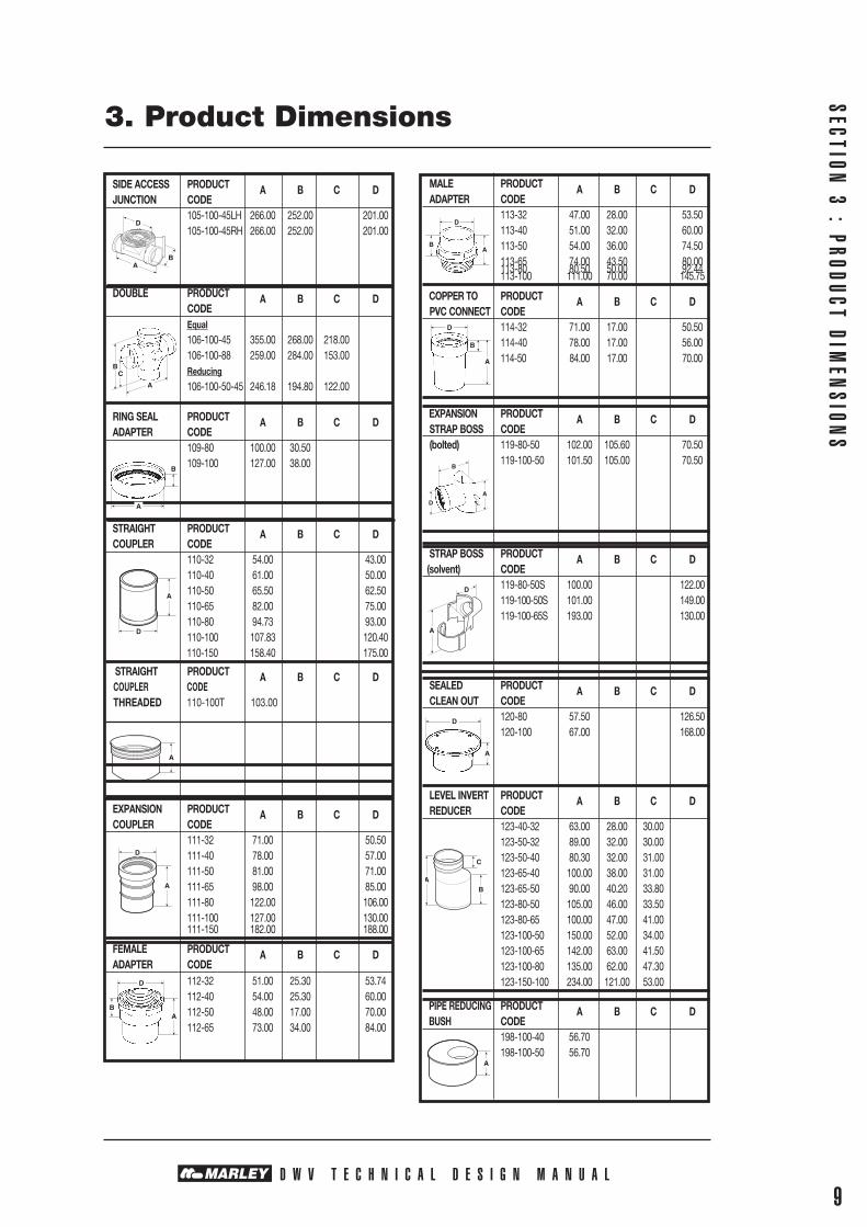
MALE PRODUCT A B C D ADAPTER CODE 113-32 47.00 28.00 53.50 113-40 51.00 32.00 60.00 113-50 54.00 36.00 74.50 113-65 74.00 43.50 80.00 113-80 80.50 50.00 92.44 113-100 111.00 70.00 145.75
COPPER TO PRODUCT A B C D PVC CONNECT CODE 114-32 71.00 17.00 50.50 114-40 78.00 17.00 56.00 114-50 84.00 17.00 70.00
EXPANSION PRODUCT A B C D STRAP BOSS CODE (bolted) 119-80-50 102.00 105.60 70.50 119-100-50 101.50 105.00 70.50
STRAP BOSS PRODUCT A B C D (solvent) CODE 119-80-50S 100.00 122.00 119-100-50S 101.00 149.00 119-100-65S 193.00 130.00
SEALED PRODUCT A B C D CLEAN OUT CODE 120-80 57.50 126.50 120-100 67.00 168.00
LEVEL INVERT PRODUCT A B C D REDUCER CODE 123-40-32 63.00 28.00 30.00 123-50-32 89.00 32.00 30.00 123-50-40 80.30 32.00 31.00 123-65-40 100.00 38.00 31.00 123-65-50 90.00 40.20 33.80 123-80-50 105.00 46.00 33.50 123-80-65 100.00 47.00 41.00 123-100-50 150.00 52.00 34.00 123-100-65 142.00 63.00 41.50 123-100-80 135.00 62.00 47.30 123-150-100 234.00 121.00 53.00
PIPE REDUCING PRODUCT A B C D BUSH CODE 198-100-40 56.70 198-100-50 56.70
SIDE ACCESS PRODUCT A B C D JUNCTION CODE 105-100-45LH 266.00 252.00 201.00 105-100-45RH 266.00 252.00 201.00
DOUBLE PRODUCT A B C D CODE Equal 106-100-45 355.00 268.00 218.00 106-100-88 259.00 284.00 153.00 Reducing 106-100-50-45 246.18 194.80 122.00
RING SEAL PRODUCT A B C D ADAPTER CODE 109-80 100.00 30.50 109-100 127.00 38.00
STRAIGHT PRODUCT A B C D COUPLER CODE 110-32 54.00 43.00 110-40 61.00 50.00 110-50 65.50 62.50 110-65 82.00 75.00 110-80 94.73 93.00 110-100 107.83 120.40 110-150 158.40 175.00
STRAIGHT PRODUCT A B C D COUPLER CODE THREADED 110-100T 103.00
EXPANSION PRODUCT A B C D COUPLER CODE 111-32 71.00 50.50 111-40 78.00 57.00 111-50 81.00 71.00 111-65 98.00 85.00 111-80 122.00 106.00 111-100 127.00 130.00 111-150 182.00 188.00
FEMALE PRODUCT A B C D ADAPTER CODE 112-32 51.00 25.30 53.74 112-40 54.00 25.30 60.00 112-50 48.00 17.00 70.00 112-65 73.00 34.00 84.00
SECTION 3 : PRODUCT DIM
ENSION
S
3. Product Dimensions
D W V T E C H N I C A L D E S I G N M A N U A L9
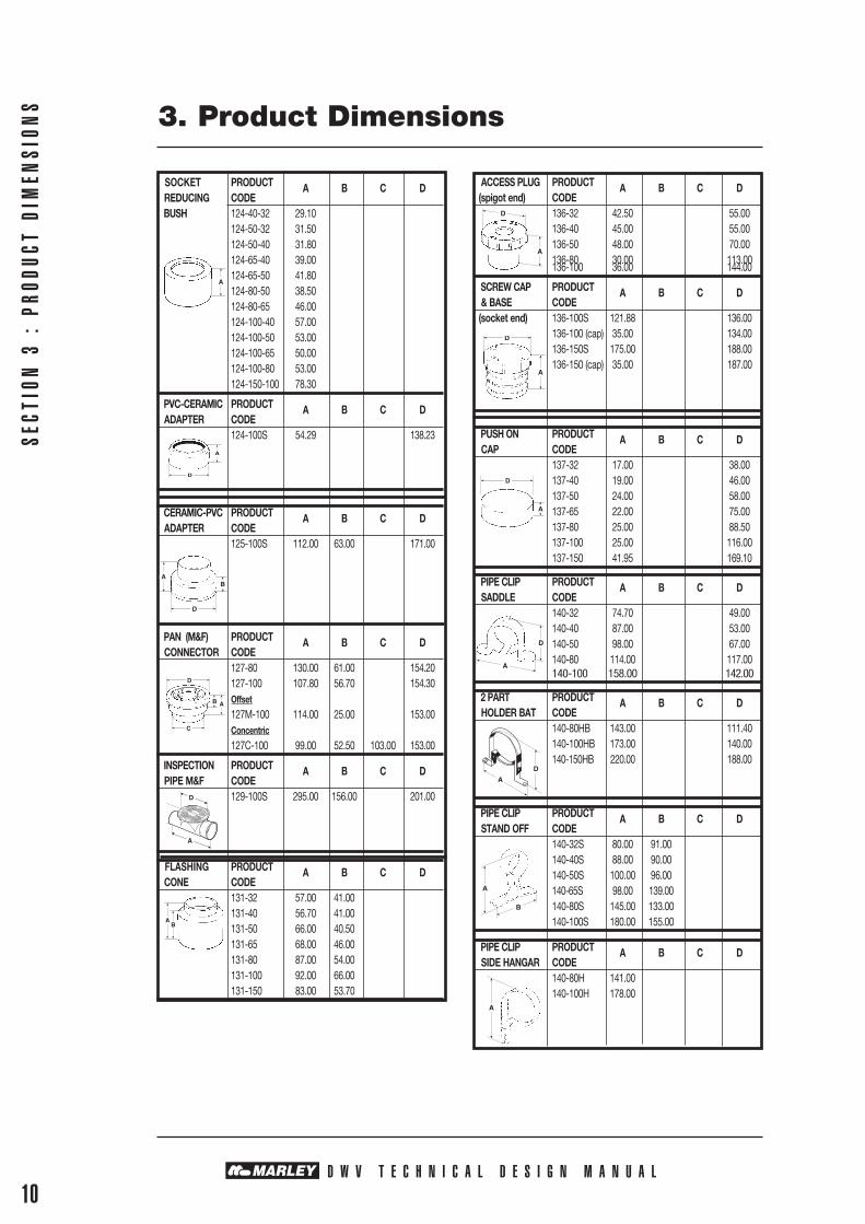
ACCESS PLUG PRODUCT A B C D (spigot end) CODE 136-32 42.50 55.00 136-40 45.00 55.00 136-50 48.00 70.00 136-80 30.00 113.00 136-100 36.00 144.00
SCREW CAP PRODUCT A B C D & BASE CODE (socket end) 136-100S 121.88 136.00 136-100 (cap) 35.00 134.00 136-150S 175.00 188.00 136-150 (cap) 35.00 187.00
PUSH ON PRODUCT A B C D CAP CODE 137-32 17.00 38.00 137-40 19.00 46.00 137-50 24.00 58.00 137-65 22.00 75.00 137-80 25.00 88.50 137-100 25.00 116.00 137-150 41.95 169.10
PIPE CLIP PRODUCT A B C D SADDLE CODE 140-32 74.70 49.00 140-40 87.00 53.00 140-50 98.00 67.00 140-80 114.00 117.00 140-100 158.00 142.00
2 PART PRODUCT A B C D HOLDER BAT CODE 140-80HB 143.00 111.40 140-100HB 173.00 140.00 140-150HB 220.00 188.00
PIPE CLIP PRODUCT A B C D STAND OFF CODE 140-32S 80.00 91.00 140-40S 88.00 90.00 140-50S 100.00 96.00 140-65S 98.00 139.00 140-80S 145.00 133.00 140-100S 180.00 155.00
PIPE CLIP PRODUCT A B C D SIDE HANGAR CODE 140-80H 141.00 140-100H 178.00
SOCKET PRODUCT A B C D REDUCING CODE BUSH 124-40-32 29.10 124-50-32 31.50 124-50-40 31.80 124-65-40 39.00 124-65-50 41.80 124-80-50 38.50 124-80-65 46.00 124-100-40 57.00 124-100-50 53.00 124-100-65 50.00 124-100-80 53.00 124-150-100 78.30
PVC-CERAMIC PRODUCT A B C D ADAPTER CODE 124-100S 54.29 138.23
CERAMIC-PVC PRODUCT A B C D ADAPTER CODE 125-100S 112.00 63.00 171.00
PAN (M&F) PRODUCT A B C D CONNECTOR CODE 127-80 130.00 61.00 154.20 127-100 107.80 56.70 154.30 Offset
127M-100 114.00 25.00 153.00 Concentric
127C-100 99.00 52.50 103.00 153.00
INSPECTION PRODUCT A B C D PIPE M&F CODE 129-100S 295.00 156.00 201.00
FLASHING PRODUCT A B C D CONE CODE 131-32 57.00 41.00 131-40 56.70 41.00 131-50 66.00 40.50 131-65 68.00 46.00 131-80 87.00 54.00 131-100 92.00 66.00 131-150 83.00 53.70
SECT
ION
3 :
PRO
DUCT
DIM
ENSI
ONS 3. Product Dimensions
D W V T E C H N I C A L D E S I G N M A N U A L10
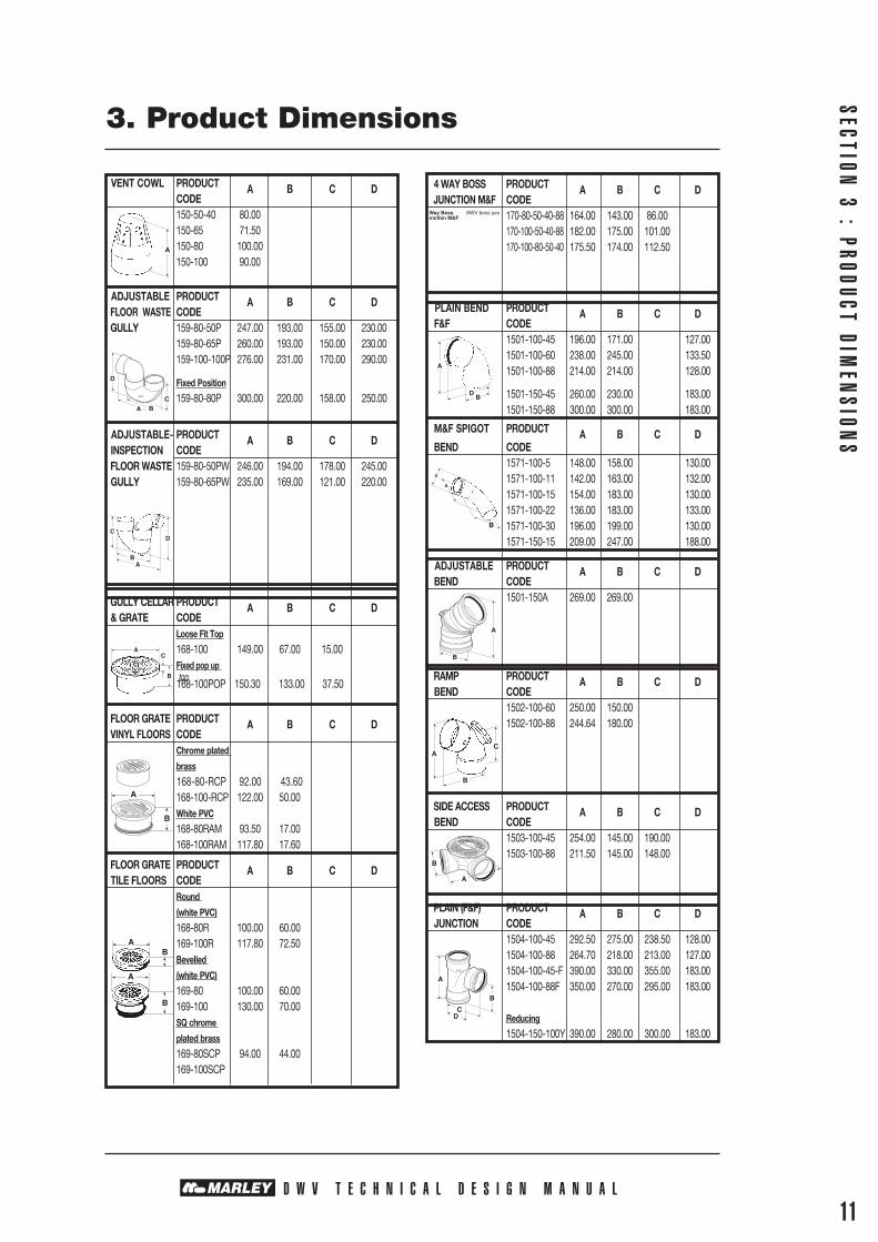
4 WAY BOSS PRODUCT A B C D JUNCTION M&F CODE 170-80-50-40-88 164.00 143.00 86.00 170-100-50-40-88 182.00 175.00 101.00 170-100-80-50-40 175.50 174.00 112.50
PLAIN BEND PRODUCT A B C D F&F CODE 1501-100-45 196.00 171.00 127.00 1501-100-60 238.00 245.00 133.50 1501-100-88 214.00 214.00 128.00
1501-150-45 260.00 230.00 183.00 1501-150-88 300.00 300.00 183.00
M&F SPIGOT PRODUCT A B C D BEND CODE 1571-100-5 148.00 158.00 130.00 1571-100-11 142.00 163.00 132.00 1571-100-15 154.00 183.00 130.00 1571-100-22 136.00 183.00 133.00 1571-100-30 196.00 199.00 130.00 1571-150-15 209.00 247.00 188.00
ADJUSTABLE PRODUCT A B C D BEND CODE 1501-150A 269.00 269.00
RAMP PRODUCT A B C D BEND CODE 1502-100-60 250.00 150.00 1502-100-88 244.64 180.00
SIDE ACCESS PRODUCT A B C D BEND CODE 1503-100-45 254.00 145.00 190.00 1503-100-88 211.50 145.00 148.00
PLAIN (F&F) PRODUCT A B C D JUNCTION CODE 1504-100-45 292.50 275.00 238.50 128.00 1504-100-88 264.70 218.00 213.00 127.00 1504-100-45-F 390.00 330.00 355.00 183.00 1504-100-88F 350.00 270.00 295.00 183.00 Reducing
1504-150-100Y 390.00 280.00 300.00 183.00
VENT COWL PRODUCT A B C D CODE 150-50-40 80.00 150-65 71.50 150-80 100.00 150-100 90.00
ADJUSTABLE PRODUCT A B C D FLOOR WASTE CODE GULLY 159-80-50P 247.00 193.00 155.00 230.00 159-80-65P 260.00 193.00 150.00 230.00 159-100-100P 276.00 231.00 170.00 290.00
Fixed Position
159-80-80P 300.00 220.00 158.00 250.00
ADJUSTABLE- PRODUCT A B C D INSPECTION CODE FLOOR WASTE 159-80-50PW 246.00 194.00 178.00 245.00 GULLY 159-80-65PW 235.00 169.00 121.00 220.00
GULLY CELLAR PRODUCT A B C D & GRATE CODE Loose Fit Top
168-100 149.00 67.00 15.00 Fixed pop up top 168-100POP 150.30 133.00 37.50
FLOOR GRATE PRODUCT A B C D VINYL FLOORS CODE Chrome plated
brass
168-80-RCP 92.00 43.60 168-100-RCP 122.00 50.00 White PVC 168-80RAM 93.50 17.00 168-100RAM 117.80 17.60
FLOOR GRATE PRODUCT A B C D TILE FLOORS CODE Round
(white PVC)
168-80R 100.00 60.00 169-100R 117.80 72.50 Bevelled
(white PVC)
169-80 100.00 60.00 169-100 130.00 70.00 SQ chrome
plated brass
169-80SCP 94.00 44.00 169-100SCP
SECTION 3 : PRODUCT DIM
ENSION
S
3. Product Dimensions
D W V T E C H N I C A L D E S I G N M A N U A L11

FRESH AIR PRODUCT A B C D INLET CODE 1516-100 152.00 102.00
LEVEL INVERT PRODUCT A B C D REDUCER CODE 1523-100-80 135.00 62.00 47.30 1523-150-100 222.00 98.00 65.00
PVC-CERAMIC PRODUCT A B C D ADAPTER CODE 1524-100 73.00 137.00 1524-150 263.00 192.00
PRESSURE/ PRODUCT A B C D SEWER CODE ADAPTER 1524-114-100 123.00
\
CERAMIC-PVC PRODUCT A B C D ADAPTER CODE 125-100S 112.00 63.00 171.00
ACCESS PRODUCT A B C D PIPE M&F CODE 1529-100 305.00 152.00 140.00 201.00 1529-150 415.00 209.00 260.00 186.00
SOCKET PRODUCT A B C D PLUG CODE 1530-100 88.00 72.00
PLAIN PRODUCT A B C D JUNCTION CODE (spigot end) 1504-150-45 435.00 295.00 160.00 1504-150-88 435.00 270.00 160.00
LUNDEN PRODUCT A B C D JUNCTION CODE (spigot end) 1504-100-LJ 740.00 230.00 500.00 1504-150-LJ 698.00 240.00 520.00 Heavy duty
Z1505H-150-LJ 740.00 230.00 500.00 Z1504H-150-100LJ 698.00 240.00 520.00
PVC-PVC PRODUCT A B C D REDUCING CODE SADDLE 1504S-150-100 365.00 210.00 280.00
SIDE ACCESS PRODUCT A B C D JUNCTION CODE 1505-100-45LH 292.00 127.80 245.00 1505-100-45RH 292.00 127.80 245.00
COMBINATION PRODUCT A B C D STANDARD/ CODE SLIP 1511-100C 160.00 COUPLER 1511S-150 236.00
RING SEAL PRODUCT A B C D COUPLER CODE 1511-150 235.00 Heavy duty
Z1511H-150 235.00
SEPTIC TANK PRODUCT A B C D JUNCTION CODE 1514-100-88 665.00 210.00
SECT
ION
3 :
PRO
DUCT
DIM
ENSI
ONS 3. Product Dimensions
D W V T E C H N I C A L 12

GULLY PRODUCT A B C D DISH CODE Complete
1575-100 214.00 135.00 252.00 300.00
Lid only 1575L-100 199.00 120.00 284.00
GULLY PRODUCT A B C D RISER CODE 1575R-100-100 100.00
1575R-100-200 200.00
1575R-100-300 300.00
PUSH ON CAP PRODUCT A B C D CODE 137-100 25.00 117.00
137-150 42.00 170.00
GULLY PRODUCT A B C D TRAP CODE 1559-100 330.00 300.00 220.00
SECTION 3 : PRODUCT DIM
ENSION
S
3. Product Dimensions
D W V T E C H N I C A L D E S I G N M A N U A L13
FWG INSTALLATION DETAIL
80Socket depth
Waterproof membrane MARLEY LEAK CONTROL FLANGE 126-LC3-80 Tiles 126-LC4-100 MARLEY RISER PIPE Timber 80mm OR 100mm MARLEY 4-WAY BOSS JUNCTION 170-80-50-40-88o
170-100-80-50-40-88o
170-100-50-40-88o
MARLEY WASTEPIPE
300 180 Base to centre of 155 water inlet Base to water seal
MARLEY ADJUSTABLE FLOOR GULLY 159-80-50P (ABOVE GROUND ONLY) 159-80-65P 159-100-100P
FLOOR GRATE168-80DW
168-100RDW
FLOOR GRATE168-80SQW
168-100SQW
FLOOR GRATE169-100

4. Installation - Waste & Vent
D W V T E C H N I C A L D E S I G N M A N U A L14
SECT
ION
4 :
IN
STAL
LATI
ON -
WAS
TE A
ND
VEN
T
SCOPE:
This section covers various aspects of pipe installation and design protocols according to the AS/NZS 3500.2.2003 for waste and vent applications. Though detailed in scope, this section only serves as a guide to general design criteria and reference to AS/NZS 3500.2.2003 is recommended.
Reference Documents
- NZ Building Code G13 Foul Water
- AS/NZS 3500.2.2003 Sanitary Plumbing and Drainage - AS1 + AS2, VM1 + VM2
INTRODUCTION
4.1 Wastes and Vents Above Ground
Plumbing Definition: Pipes above ground floor slabs, including individual waste pipes from fixtures into a floor waste gully.
A plumbing system designed in accordance with AS/NZS 3500.2.2003 utilises appropriately sized pipes and fixture traps and offers architects, engineers and installers considerably more flexible design options.
4.2 AS/NZS 3500.2.2003
AS/NZS 3500.2.2003 offers design flexibility in that:
• Fixtures can more easily be sited internally up to 20m unvented, via a sealed ORG (overflow relief gully) from the main drain to the seal of the fixture trap.
• The number of vents required is reduced. • Floor drains can be used as shower wastes.• Under-slab drainage installation is provided without the need for ducting of pipes.• The size of terminal vents is reduced.• External gully traps are minimised.• The number of access junctions required is reduced.• The number of fixture traps can be reduced.• The risk of surface stormwater invasion of sewer systems and the likelihood of
mis-connections are minimised.
AS/NZS 3500.2.2003 offers considerable cost savings:
There are three important features of AS/NZS 3500.2.2003 that make up its key differences for residential and low rise commercial applications:
1. The use of a trapped floor waste gully trap (FWG) as a common internal collection point for waste water fixtures that occur within the same room as the FWG.
2. Ground floor fixtures (except kitchen sinks and dishwashers) may be connected directly to the vented house drain, thereby eliminating individual back vents and minimising external gully traps.
3. Fixtures on elevated timber or upper floors may be connected together on a “roll-over” single-stack vented system and then connected directly to the house-drain, eliminating individual back vents and minimising waste pipe and external gully traps.

4.3 Floor Waste Gully (FWG) Layout
Floor waste gullies are generally used to drain wet areas.
Risers and riser boss junctions must sit vertically between the floor grate and the gully trap. The riser boss junction takes the individual fixture waste pipes into the gully riser. The diameter is determined by the proximity of the highest inlet pipe to the top of the floor grate. The higher the inlet the greater the diameter of the riser.
Height of gully riser: The height of the riser shall be measured from top of water seal to the floor surface level and shall comply with the following:
(a) The maximum height shall comply with the Table Below. (b) The maximum height shall be 600 mm.
Minimum outlet size of floor waste gully traps
Waste fixtures connected Size of gully riser Minimum height to gully riser (water seal to floor level) DN 881/2° entry
All permitted waste fixtures 80 200 including maximum one bath 100 150
Where excessive foaming is likely to occur, a washing machine discharge pipe should be connected directly into either a branch or main drain.
4.4 DISCHARGE PIPE SIZING Minimum outlet size of floor waste gully trapsTotal fixture unit rating of waste Outlet size of floor waste fixtures connecting to floor waste gully gully trap 3 DN 50 10 including 1 Bath DN 65 10 or more DN 80 or greater
The Floor Grate: A removable floor grate of 80mm or 100mm
diameter (depending on the size of the riser) is set flush to the floor at the top of the riser.
Floor Seal Flanges:
Products such as leak control flanges may also be required for elevated timber and concrete floors, to ensure compliance with NZBC requirements.
4. Installation - Waste & Vent
D W V T E C H N I C A L D E S I G N M A N U A L15
SECTION 4 : IN
STALLATION - W
ASTE AND VEN
TTypical Wet Area Layout for AS/NZ 3500.2.2 Figure 4.1INDIVIDUAL FIXTURE WASTE PIPES
DIAMETER - DN40 min
LENGTH Trapped 2.5M
Untrapped 1.2M FLOOR GRATE
NOTE:Kitchen waste must not be connected to a floor waste gully (Basin waste must be trapped) OUTLET PIPE (sized by number of discharged units)
ELEVATED - DN50,65,80 or 100 RISER
BOSS BELOW SLAB - DN65,80, or 100
TRAP DN80 OR DN100 Bed in concrete when below slab
The Gully Trap: A standard P-type trap of DN80 or
DN100 diameter. The outlet size is determined by the total number of fixture discharge units through the FWG.

SECT
ION
4 :
IN
STAL
LATI
ON -
WAS
TE A
ND
VEN
T 4. Installation - Waste & Vent
D W V T E C H N I C A L D E S I G N M A N U A L16
4.5 Fitting Detail for Grate, Riser and Boss Junction
Marley FWG Assembly:
4.6 Typical Layout of Ground Floor Drainage (minimum pipe sizes and maximum permissible lengths
4.7 Fixture Detail
4.7.1 Basins:
AS/NZS 3500.2.2 All wash basins and drinking fountains must be trapped, whether discharged through a floor waste gully or directly connected to a drain or stack.
MARLEY LEAK CONTROL FLANGE VINYL 126-LC3-80 126-LC4-100
CONCRETE MARLEY RISER PIPE 80mm OR 100mm
MARLEY 4-WAY BOSS JUNCTION 170-80-50-40-88o
170-100-80-50-40-88o
MARLEY 170-100-50-40-88o
WASTEPIPE
MARLEY ADJUSTABLE FLOOR GULLY 159-80-50P (ABOVE GROUND ONLY) 159-80-65P 159-100-100P
Waterproof membrane MARLEY LEAK CONTROL FLANGE 126-LC3-80 Tiles 126-LC4-100 MARLEY RISER PIPE Timber 80mm OR 100mm MARLEY 4-WAY BOSS JUNCTION 170-80-50-40-88o
170-100-80-50-40-88o
170-100-50-40-88o
MARLEY WASTEPIPE
300 180 Base to centre of 155 water inlet Base to water seal
MARLEY ADJUSTABLE FLOOR GULLY 159-80-50P (ABOVE GROUND ONLY) 159-80-65P 159-100-100P
80Socket depth
Terminal Vent DN50(Reduced at floor level)
BACK INLET GULLY OROVERFLOW RELIEF GULLY
ALL PIPE LENGTHSARE MAXIMUMS
ALL PIPE DIAMETERSARE MINIMUMS
WASTE PIPE DIAMETERS50mm Kitchen sink40mm All other wastes
ACCESSJUNCTION
ACCESSJUNCTION
TO MAIN SEWER
FLOOR WASTE GULLY
OVERFLOW RELIEF PIPE
DISCONNECTOR GULLY
acceptable but generally not a
good methodSEALED CLEAN OUT
Kitchen Sink
Reduced at floor level
10m max including 2.5m sanitary plumbing
2.5M
DN50 2.5M ‘P’trap
DN50 2.5M ‘P’trap
2.5M
10MDN 100
10MDN 65
DN 6510M
DN 80
10MDN 80
10MDN 65
7.5MDN 65
DN 65
DN 100
DN 100
FLOOR GRATE168-80DW
168-100RDW
FLOOR GRATE168-80SQW
168-100SQW
FLOOR GRATE169-100
VINYL RITE FLOOR WASTE SYSTEMVR80WHVR100WH
4. Installation - Waste & Vent
SECTION 4 : IN
STALLATION - W
ASTE AND VEN
T
D W V T E C H N I C A L D E S I G N M A N U A L17
4.7.2 Floor Waste Gully (FWG):
Shall have no more than 2 bends in a horizontal plane and 3 bends in a vertical plane, to collect discharge from waste fixtures within the same room, with a maximum of 10m of pipe from the main drain before venting.
4.7.3 Baths, Showers and Washing Machines:
These can all be run in DN40 or DN50 diameter pipe, either directly to a main drain or stack, or into a floor waste gully and from there, via a minimum DN65 diameter branch drainage pipe, directly to the main house drain or to an Overflow Relief Gully.
NOTE: Where excessive foaming is likely to occur, a washing machine discharge pipe should be connected directly into either a branch or main drain.
4.7.4 Kitchen Sinks:
AS/NZS 3500.2.2 requires that all kitchen sink outlets, traps and waste pipes are minimum DN40 and may connect directly to the main house drain via a larger branch drain pipe or through an Overflow Relief Gully. Kitchen sinks and dishwashers may not discharge into an FWG.
4.7.5 Laundry Tubs:
Laundry tub wastes may be run in either DN40 or DN50 into its own Floor Waste Gully or preferably directly into the main house drain (due to foaming) via a larger branch drain, or through an Overflow Relief Gully.
4.7.6 Bends:
Fixtures other than basins and bidets, shall have no more than 2 bends on a horizontal plane and 3 bends on the vertical plane.
NOTE: A bend of 45° or less is not considered as a change of direction or grade.4.8 Waste Pipe Discharge
Fixtures on either the upper floor or on the ground floor can be connected to the house drain via individual waste pipes to an external gully. However, waste pipes to an external gully must run above the ground floor slab level.
Allowable distances for this type of connection vary according to whether they are vented or unvented.
Unvented Fixtures
Size Fixtures Distance
DN40 Basin 3.6m
DN 40 All Fixtures for these sizes 6.0m
DN 50 All Fixtures for these sizes 6.0m
DN 65 All Fixtures for these sizes 10m
Alternatively utilising a floor waste gully will allow the total distance from the main drain or stack to be 10m. A fixture trap connected to a FWG will provide an additional 2.5m when measure from the wier of the fixture trap.
4.9 Waste Stacks Refer AS/NZS 3500.2.2
Waste stacks must be sized so that they receive the discharge from waste fixtures and have the size, length and grade of the discharge pipe identical to the single stack system.
4.9.1 Sizing of Stacks Refer AS/NZS 3500.2.2
It should be noted that not more than 1/4 of the maximum loading is to discharge into the stack at any one floor level.

4. Installation - Waste & Vent
SECT
ION
4 :
IN
STAL
LATI
ON -
WAS
TE A
ND
VEN
T
D W V T E C H N I C A L D E S I G N M A N U A L18
Size of Stack Maximum Fixture Unit Loading 40mm 2
50mm 6
65mm 15
80mm 30
100mm 120
4.9.2 Waste Stacks 65mm (Refer AS/NZS 3500 2.2 Clause 8.8.8) 65mm waste stacks can receive the
discharge from kitchen sinks and laundry tubs, provided that:
a) The stack does not exceed 2 floor levels, and
b) no more than 2 kitchen sinks or 1 kitchen sink plus 1 laundry tub are separately connected at each floor level.
4.9.3 50mm Vertical Section of a Soil & Waste Stack
Refer AS/NZS 3500 2.2 clause 8.8.9.
A maximum of 3 waste fixtures, basins, showers or kitchen sinks may be connected to the top of a 50mm vertical section of a stack, provided that the stack does not exceed 3 floors or does not exceed 30 fixture unit loading.
Refer AS 3500 part 2clause 7.12.2.3 (a)
Refer AS 3500 part 2clause 7.12.2.5 (b)
Refer AS 3500 part 2clause 7.12.2.5 (b)
Refer AS 3500 part 2clause 7.2.12.2.4
Inspection fitting
Expansion point
Typical flat offset for single dwellingwith sanitary stackwork up to two floors
Roof
Second floor
First floor
Ground floor
Flow
450
600
2500
600
1000 min
Stack Vent
900 min
600 min
Stack not to exceed DN100
100mm WITH GRADED OFFSET
Vent Pipe DN50
Bath
Sink
Shower
ALL DIMENSIONS IN MM
4. Installation - Waste & Vent
SECTION 4 : IN
STALLATION - W
ASTE AND VEN
T
D W V T E C H N I C A L D E S I G N M A N U A L19
4.10 Above In and Below Concrete Slab Installation Detail
In these installations, consideration should be given to catering for expansion and contraction by one of the following methods:
“Below” Slab Installations: Firm bedding in clean sand using sleeving and/or dry packing where pipes penetrate the slab, or install a larger outer ducting to carry the service pipe.
“In” Slab Installations: Install a larger duct to carry the service pipe or wrap the pipe in polyethylene, felt
densotape or foam membrane.
Under Slab: Any pipe running under a concrete slab floor from a fixture directly to the main house drain
is deemed to be a “drain”. As such it must be at least DN65 and connected as if a drain.
Other important points to remember in connection with installations in or under concrete slab floors:
a) Any waste pipe running to an external gully must run above the slab for its entire length, or considered a drain if dropped below slab level.
b) Individual waste pipes running under a concrete slab floor from a fixture to an FWG are simply considered an extension of the above-floor waste pipe and may be treated as such.
c) All pipes in or below concrete should be installed in straight runs.d) Expansion and contraction of PVC drains must be catered for when installing in
concrete.
4.11 Important Design Considerations
1. Kitchen sinks and WCs cannot discharge into an FWG.2. All basins and any drinking fountains must always be individually trapped.3. Fixtures (other than in 2 above) with outlets 1.2m or less from the FWG do not require
traps.4. All fixtures with outlets between 1.2m and 2.5m from an FWG must be trapped.5. All waste pipes discharging to an FWG must be a minimum of DN40.6. Fixtures discharging to an FWG must be located in the same room as the FWG.7. Individual fixture pipes to an FWG should be as straight as possible. 8. Under a slab, changes in direction, if required, should be made at the riser boss.9. No venting is permitted on any individual waste pipes discharging to an FWG.10. A floor waste gully assembly may be used as an “in floor” shower outlet.11. The discharge pipe from an FWG to the main drain is sized by the number of fixture
units entering the FWG. Minimum pipe size is 65DN.12. Where foaming is likely to cause a problem, fixtures should not discharge through an
FWG.
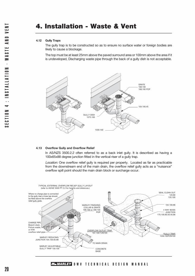
4.12 Gully Traps
The gully trap is to be constructed so as to ensure no surface water or foreign bodies are likely to cause a blockage.
The top must be at least 25mm above the paved surround area or 100mm above the area if it is undeveloped, Discharging waste pipe through the back of a gully dish is not acceptable.
4.13 Overflow Gully and Overflow Relief
In AS/NZS 3500.2.2 often referred to as a back inlet gully. It is described as having a 100x65x88 degree junction fitted in the vertical riser of a gully trap.
Location: One overflow relief gully is required per property. Located as far as practicable from the downstream end of the main drain, the overflow relief gully acts as a “nuisance” overflow spill point should the main drain block or surcharge occur.
4. Installation - Waste & Vent
SECT
ION
4 :
IN
STAL
LATI
ON -
WAS
TE A
ND
VEN
T
D W V T E C H N I C A L D E S I G N M A N U A L20
SEAL CLEAN OUT120.80
120.100
4 WAY BOSSJUNCTION
170.100.80.50.40.88
104.100.88
GULLY TRAP1559.100 DN100
OVERFLOW OUTLET TRAP167.100 DN100
MARLEY FINISHING COLLAR & GRATE
168.100 or 168.100 POP
TO MAIN DRAIN
CONCRETEBASE
MARLEY ADJUSTABLEGULLY TRAP 159.100
MARLEY REDUCINGJUNCTION 104.100.65.88
CHARGE PIPEBranch drain, Fixture waste, or H/W overflow relief pipe
TYPICAL EXTERNAL OVERFLOW RELIEF GULLY LAYOUT(refer to AS/NZ 3500 PT 2.2 for heights and distances.)
Where no charge pipe is connected to the gully riser a hose tap should be fitted above the overflow relief gully grate.
DN100
GRATE 168.100168.100 POP
104.100.45
1559.100
GULLY DISH1575.100
4. Installation - Waste & Vent
SECTION 4 : IN
STALLATION - W
ASTE AND VEN
T
D W V T E C H N I C A L D E S I G N M A N U A L21
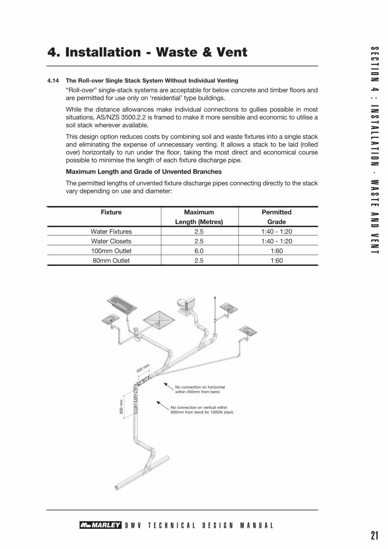
4.14 The Roll-over Single Stack System Without Individual Venting
“Roll-over” single-stack systems are acceptable for below concrete and timber floors and are permitted for use only on ‘residential’ type buildings.
While the distance allowances make individual connections to gullies possible in most situations, AS/NZS 3500.2.2 is framed to make it more sensible and economic to utilise a soil stack wherever available.
This design option reduces costs by combining soil and waste fixtures into a single stack and eliminating the expense of unnecessary venting. It allows a stack to be laid (rolled over) horizontally to run under the floor, taking the most direct and economical course possible to minimise the length of each fixture discharge pipe.
Maximum Length and Grade of Unvented Branches
The permitted lengths of unvented fixture discharge pipes connecting directly to the stack vary depending on use and diameter:
Fixture Maximum Permitted Length (Metres) Grade Water Fixtures 2.5 1:40 - 1:20
Water Closets 2.5 1:40 - 1:20
100mm Outlet 6.0 1:60
80mm Outlet 2.5 1:60
No connection on horizontal within 450mm from bend.
No connection on vertical within 600mm from bend for 100DN stack.60
0 m
m
450 mm
4. Installation - Waste & Vent
SECT
ION
4 :
IN
STAL
LATI
ON -
WAS
TE A
ND
VEN
T
D W V T E C H N I C A L D E S I G N M A N U A L22
4.15 80mm Roll-over Stacks
• Every waste fixture is to be connected either individually to the stack or through an FWG, an unequal oblique junction or fixture pairs.
• No laundry tub or clothes washing machine can be connected.• No fixtures are connected to the stack’s lower vertical section.• Only one of each of the following fixtures may be connected to the stack’s horizontal
section: • Bath • Basin • Dishwasher • Kitchen sink • Shower • Water closet pan• No connection is to be made in the horizontal section of the stack within 450mm of the
stack’s downstream bend.
If these conditions cannot be met then an unvented 80mm roll-over stack system is inappropriate. The alternatives are either to vent all fixtures or to install a 100mm stack, for which there are fewer limitations.
4.16 100mm Roll-over Stacks
Residential building of no more than two floors.
No individual trap vents are required in a 100mm roll-over stack system, provided the following conditions are met:
• Every waste fixture is to be connected either individually to the stack or through an FWG, fixture pairs, or an unequal oblique junction.
• No connection is to be made on the horizontal section within 450mm of the stack’s down-stream bend.
• Branches must not connect within the top 600mm of the vertical section of the stack.
4.17 Restricted Entry Zones
Restricted Entry Zone Requirements - Refer AS/NZS 3500.2.2 Table 6.4.
Discharge Pipe Nominal Stack Size Restricted Entry Zone Size mm mm Vertical Depth mm
40 to 65 40 to 80 90
40 to 65 100 110
80 or larger 80 or larger 200
Branch connection
Discharge stack
Y junction
Swept junction or45o junction
Restricted zone
Branch connection
Discharge stack
200
4. Installation - Waste & Vent
SECTION 4 : IN
STALLATION - W
ASTE AND VEN
T
D W V T E C H N I C A L D E S I G N M A N U A L23
4.18 Inspection Openings (Refer AS/NZS 3500.2.2 Clause 9.5.1 A-E)
All pipes conveying soil discharges should have inspection openings located as follows:
• Where required for testing.• At junctions that connect any graded pipe or branch to a stack.• At least 30m intervals on grade pipes.• At the base of every stack.• At the first bend downstream from the soil fixture trap outlet.• At the upstream section of such grade pipe or branch.
4.19 Rating of Vents
Where two or more vents are directly connected to a drain, these vents may take the place of the single vent. The sum of the ratings must be equal to or greater than the vent rating for the single vent.
Size and Rating of Vents
Size of Vent Pipe Fixture Units Vent Rating DN Discharging to Drain
40 <1 ≤10 0.5
50 <10 ≤30 1
65 <30 ≤175 2
80 <175 ≤400 3
100 <400
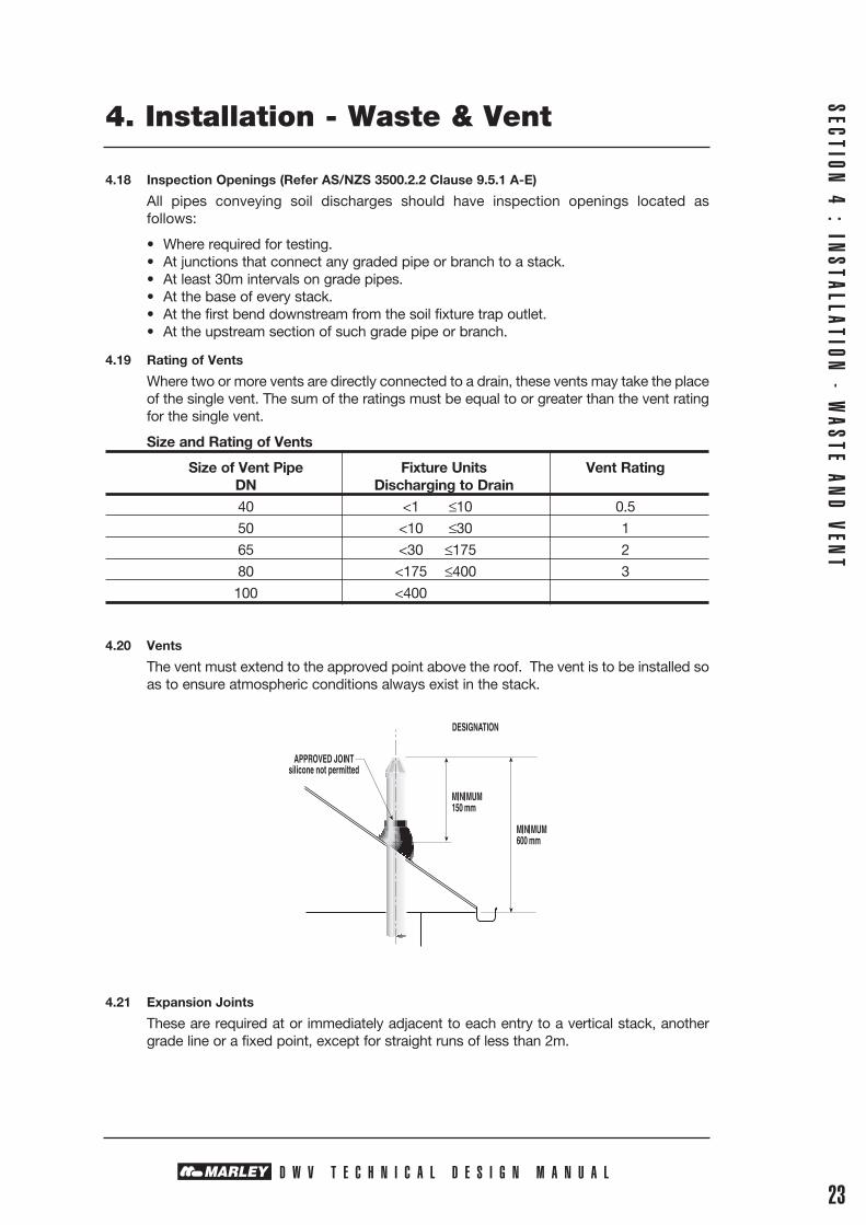
4.20 Vents
The vent must extend to the approved point above the roof. The vent is to be installed so as to ensure atmospheric conditions always exist in the stack.
4.21 Expansion Joints
These are required at or immediately adjacent to each entry to a vertical stack, another grade line or a fixed point, except for straight runs of less than 2m.

4. Installation - Waste & Vent
SECT
ION
4 :
IN
STAL
LATI
ON -
WAS
TE A
ND
VEN
T
D W V T E C H N I C A L D E S I G N M A N U A L24
4.22 Bracket Spacing
Bracket spacing in metres in accordance with AS/NZS 3500.2.2 Nominal pipe size Graded Pipe Vertical Pipe
40 1 2
50 1 2
65 1.2 2.5
80 1.2 2.5
90 1.2 2.5
100 1.2 2.5
150 1.2 2.5
175 1.7 2.8
200 2.0 3.1
225 2.2 3.4
250 2.3 3.6
300 2.5 4
375 3.0 4.4
Vent
Approved joint.Silicon not permitted
Expansion joint May be deleted.
Refer AS 2032 clause 6.6.4 (a)
Fixed point clip
Expansion joint Refer AS 2032
clause 6.6.2 (b)
Fixed point clip
Expansion joint Refer AS 2032 clause 6.6.3 (a)
Fixed point clip
Inspection fitting
Expansion joint Refer AS 2032 clause 6.6.2 (b)
Expansion joint Refer AS 2032 clause 6.6.2 (a)
150 mm minimum
600 mm minimum
Eaves
Vertical stack
4.22.1 Bracket Spacing Above Ground Installations for Rollover Stacks
Pipe support should be as per Table 4.22. However, fittings support needs to be included at every junction and change of direction. When the gradient is below 1:20 or the line is subject to heat loading from dishwasher or similar appliances.
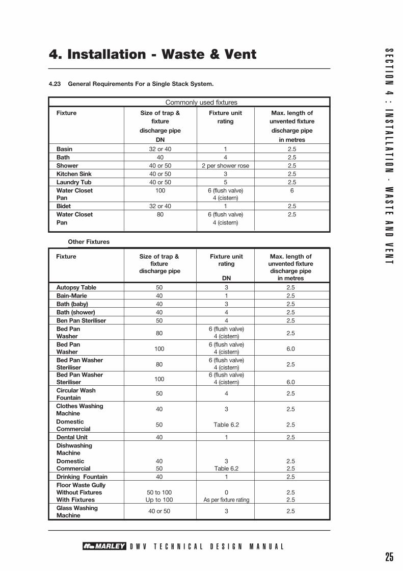
4.23 General Requirements For a Single Stack System.
Commonly used fixtures
Fixture Size of trap & Fixture unit Max. length of fixture rating unvented fixture
discharge pipe discharge pipe
DN in metres
Basin 32 or 40 1 2.5 Bath 40 4 2.5 Shower 40 or 50 2 per shower rose 2.5 Kitchen Sink 40 or 50 3 2.5 Laundry Tub 40 or 50 5 2.5 Water Closet 100 6 (flush valve) 6 Pan 4 (cistern) Bidet 32 or 40 1 2.5 Water Closet 80 6 (flush valve) 2.5 Pan 4 (cistern)
Other Fixtures
Fixture Size of trap & Fixture unit Max. length of fixture rating unvented fixture discharge pipe discharge pipe DN in metres
Autopsy Table 50 3 2.5 Bain-Marie 40 1 2.5 Bath (baby) 40 3 2.5 Bath (shower) 40 4 2.5 Ben Pan Steriliser 50 4 2.5 Bed Pan 6 (flush valve) Washer 80 4 (cistern) 2.5
Bed Pan 6 (flush valve) Washer 100 4 (cistern) 6.0
Bed Pan Washer 6 (flush valve)
Steriliser 80 4 (cistern) 2.5
Bed Pan Washer 6 (flush valve) Steriliser 100 4 (cistern) 6.0 Circular Wash 50 4 2.5 Fountain Clothes Washing 40 3 2.5 Machine Domestic 50 Table 6.2 2.5 Commercial Dental Unit 40 1 2.5 Dishwashing Machine Domestic 40 3 2.5 Commercial 50 Table 6.2 2.5 Drinking Fountain 40 1 2.5 Floor Waste Gully Without Fixtures 50 to 100 0 2.5 With Fixtures Up to 100 As per fixture rating 2.5 Glass Washing 40 or 50 3 2.5 Machine
SECTION 4 : IN
STALLATION - W
ASTE AND VEN
T
D W V T E C H N I C A L D E S I G N M A N U A L25
4. Installation - Waste & Vent

SECT
ION
4 :
IN
STAL
LATI
ON -
WAS
TE A
ND
VEN
T
D W V T E C H N I C A L D E S I G N M A N U A L26
4. Installation - Waste & Vent
Notes:
Fixture Size of trap & Fixture unit Max. length of fixture rating unvented fixture discharge pipe discharge pipe DN in metres
Sink Single or Double with or 40 or 50 3 2.5 Without Disposal Tea Sink 50 1 2.5 Domestic Bar Sink 40 1 2.5 Commercial Bar Sink 50 3 2.5 Cleaner Sink 40 or 50 1 2.5 Laboratory Sink 50 1 2.5 Sink (Pot or Utility) 50 5 2.5 Slop Hopper 100 6 (flush valve) 6.0 .
Trough (Ablution) 32, 40 or 50 3 2.5 Trough (Laundry) 5
Urinal Wall hung 50 or 80 1 2.5 Urinal, Stall or each 600mm 100 1 6.0 Length of Slab Bathroom Combination in a single room (Basin 6
Bath, Shower, WC) Combination Pan Room, Sink & 80 6 (flush valve) 2.5 Flushing Bowl 4 (cistern) Combination Pan 6 (flush valve) Room Sink 100 4 (cistern) 6.0

D W V T E C H N I C A L D E S I G N M A N U A L
SECTION 5 : IN
STALLATION &
LAYOUT - DRAINS
27
5. Installation & Layout - Drains
DRAINS BELOW GROUND
5.1 Inspection Openings
Marley inspection openings are to be installed at:
• Not more than 30 metre intervals where soil fixtures are connected.
• Outside the building on branches connecting one or more water closets, but no greater than 2.5m away from the building.
• On the downstream end where any drain passes under a building, except where waste fixtures only are connected.
• Where any new section of drain is connected to any existing drain.
5.2 Bends
Any pipe layout must be planned to reduce the risk of blockages.• Use the least number of bends by planning a simple layout.• Use the maximum bending radius in all bends installed to minimise blockage potential.• Lay in straight lines between bends (both horizontally and vertically)
5.3 Junctions
Any connection must be made by means of a sweep inspection junction, or Marley London junction on a main line. The angle that the branch makes with the main drain shall not be greater than 60°.
5.4 Gradient - Number of Discharge Units
All sanitary drains should be laid at a minimum gradient of 1:60 or greater if practical. Lower gradients can be used but they will have an effect on the number of discharge units that can be connected.
Dia Gradient
DN 1:20 1:40 1:60 1:80 1:100
80 215 100 61 44 34
100 515 255 205 149 122
150 2920 1790 1310 1040 855
5.5 Excavation
The recommended trench depth should be determined by the proposed surface-imposed loading plus the soil loading based on the depth. The depth should be sufficient to ensure there is no damage to the pipe during its intended service life. See section 10.7 for maximum recommended depth and embedment compaction.
5.6 Excavation - Special Conditions
Trench support requirements must be observed. OSH have standard guidelines for installers, safety and these should always be complied with.
When shoring or stepping is used, care needs to be taken that no voids are left as the shoring is removed and the compaction density of the backfill is achieved.
Removeablecover
(a) Horizontal connection
60o max
60o max
Groundlevel
(b) Vertical connection
Branchline
Maindrain
Flow
Flow
Flow
Flow

SECT
ION
5 :
IN
STAL
LATI
ON &
LAY
OUT
- D
RAIN
S
D W V T E C H N I C A L D E S I G N M A N U A L28
5. Installation & Layout - Drains
5.7 Trench Width
Trench width should be as narrow as practical, leaving enough space each side of the pipe to allow for compaction. Narrower trenches result in less disruption to local services, achieve faster excavations and minimise loads imposed on the pipe.
The minimum trench width is 200mm wider than the pipe
Nominal Narrow Trench Wide Trench Diameters Width (mm) Width (mm) 100 310 800
150 360 830
175 400 900
225 450 950
300 515 1000
375 600 1200
5.8 Pipe Laying
Before pipe installation, each pipe should be checked to see that its bore is free from foreign matter and that the pipe exterior and the socket have not been damaged in handling or storage.
Pipes should be laid in straight lines between bends both horizontally and vertically.
5.9 Pipe Bed Preparation
The pipe bed should give firm, even support. The trench should be excavated 80-150 mm below the invert to allow pipe bedding material to be placed.
Where the natural ground provides an inadequate foundation, the trench should be over excavated and selected hardfill compacted in place to provide adequate pipe support. Compact hard fill should be used to make up for any over excavation of the trench.
A groove should be dug under each socket ring groove to ensure the pipe barrel is uniformly supported along its length.
5.10 Bedding
The pipe bedding material should be non-cohesive (free running), granular, crushed rock, free from sharp stones larger than 25mm and free from lumps of clay or soil larger than 75mm. The material excavated from the trench may be reused if dry, well broken and free of lumps which would prevent adequate compaction or create point loads. When bedding with fine sand, special precaution is required to ensure that this material is not washed into the rubber ring seal.
5.11 Side Support and Backfill
Bedding material should be used for side support, and should be tamped each side of the pipe to a minimum height of 150mm above the crown of the pipe. Particular care must be taken not to leave any voids or disturb the line or gradient or damage the pipe.
Special care is required with large diameter pipes to ensure the side support is adequately compacted to minimise pipe ovality when the backfill is compacted to the density requirement.
When the pipe has passed the required testing and the pipe and fittings are covered and tamped with appropriate side fill, backfilling with excavated or imported material (depending on loading requirements) can proceed.
D W V T E C H N I C A L D E S I G N M A N U A L
No mechanical compaction should proceed until at least 300mm of backfill has been placed over the sidefill.
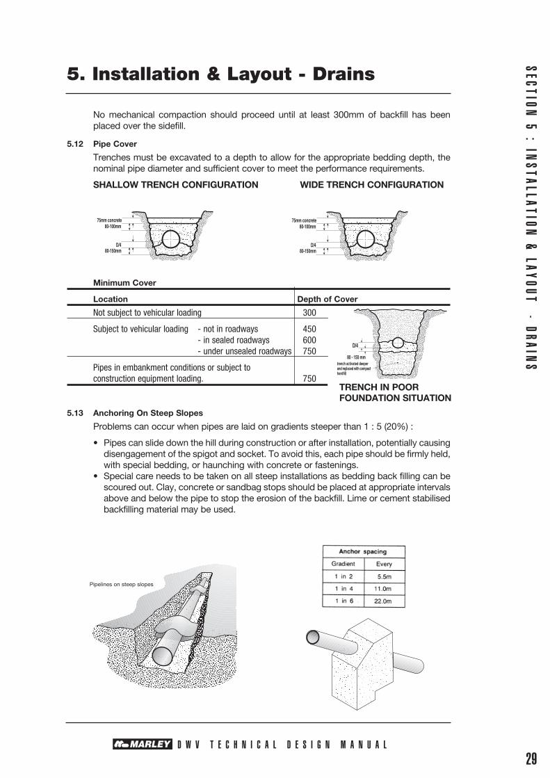
5.12 Pipe Cover
Trenches must be excavated to a depth to allow for the appropriate bedding depth, the nominal pipe diameter and sufficient cover to meet the performance requirements.
SHALLOW TRENCH CONFIGURATION WIDE TRENCH CONFIGURATION
Minimum Cover
Location Depth of Cover
Not subject to vehicular loading 300
Subject to vehicular loading - not in roadways 450 - in sealed roadways 600 - under unsealed roadways 750
Pipes in embankment conditions or subject to construction equipment loading. 750 WI
5.13 Anchoring On Steep Slopes
Problems can occur when pipes are laid on gradients steeper than 1 : 5 (20%) :
• Pipes can slide down the hill during construction or after installation, potentially causing disengagement of the spigot and socket. To avoid this, each pipe should be firmly held, with special bedding, or haunching with concrete or fastenings.
• Special care needs to be taken on all steep installations as bedding back filling can be scoured out. Clay, concrete or sandbag stops should be placed at appropriate intervals above and below the pipe to stop the erosion of the backfill. Lime or cement stabilised backfilling material may be used.
29
5. Installation & Layout - Drains
SECTION 5 : IN
STALLATION &
LAYOUT - DRAINS
75mm concrete80-100mm
D/480-150mm
75mm concrete80-100mm
D/480-150mm
TRENCH IN POOR FOUNDATION SITUATION
Pipelines on steep slopes
SECT
ION
5 :
IN
STAL
LATI
ON &
LAY
OUT
- D
RAIN
S
D W V T E C H N I C A L D E S I G N M A N U A L30
5. Installation & Layout - Drains
5.14 Pipe Bending Radius
Before attempting to induce any curvature, always joint two pipes when they are straight, to avoid dislodging the rubber ring. Rubber ring joints can be deflected up to 3%. Greater changes in direction can be achieved using shorter pipe lengths or formed bends. For smaller pipe sizes, PVC is flexible enough to be subjected to limited bending. The curvature induced should take place over the full length of the pipe.
Joints should be well compacted or sand bagged to ensure that the joint is not deflected more than 3°.
The minimum bending radius of 300 times the diameter should not be exceeded, ie 100mm pipe recommended minimum radius of 30m.
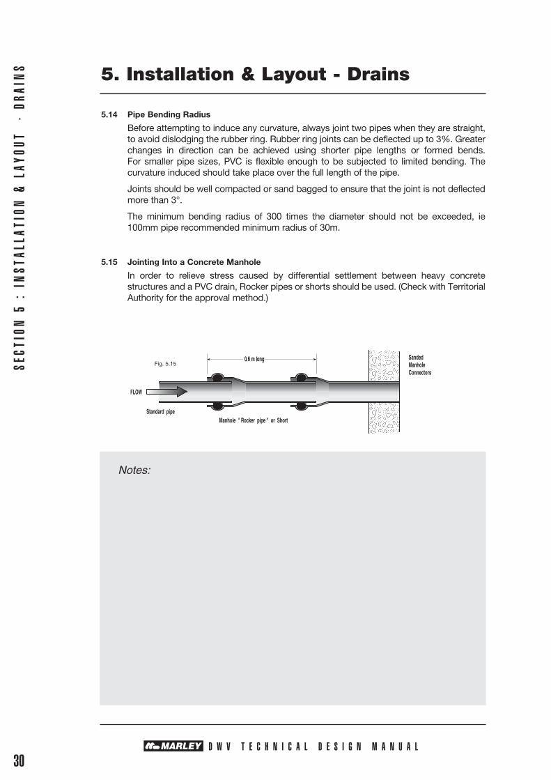
5.15 Jointing Into a Concrete Manhole
In order to relieve stress caused by differential settlement between heavy concrete structures and a PVC drain, Rocker pipes or shorts should be used. (Check with Territorial Authority for the approval method.)
Notes:
Fig. 5.15

D W V T E C H N I C A L D E S I G N M A N U A L
SECTION 6 : TESTIN
G & COM
MISSION
ING
6. Testing & Commissioning
Testing should meet the Territorial Authority requirements. Prior to testing, seal all openings in the pipeline below the top of the section being tested. It is Marley’s recommendation that all pipelines be tested before placing backfill in the trench. Conventional test plugs are suitable, provided the rubbers are in good condition.
6.1 Hydrostatic Testing Method
Fill the pipeline with water so a maximum height of no more than 6m is applied to the lowest end of the pipe section under test.
With drains, the line must be filled to no less than 1.5 metres above the natural ground level at the highest point.
Each joint shall be carefully examined for leaks. The pressure shall be held for at least 15 minutes.
The pipeline system passes a test if the visual inspection shows no evidence of leaks.
Maximum permissible volume of makeup water
Nominal Pipe Diameter Maximum permissible makeup
water per 100m of pipe (litres)
100 1.5
150 2.25
175 2.9
250 3.6
315 4.5
375 7.2
6.2 Air Test Method
Pump air into the fully sealed pipe system until the air pressure differential of 300mm of water registers on a suitable water manometer.
Disconnect the air supply and observe the gauge for 5 minutes.
If the pipeline will not hold pressure, visually inspect all of the joints by pouring a soapy water solution over the joints to detect the leaking areas.
The pipeline is considered to have passed the test if the pressure drop in the pipeline does not exceed 50mm ( i.e. 300mm down to 250mm head ).
6.3 Infiltration
Marley PVC DWV lines will have no infiltration even under a higher ground water level, although allowance must be made for infiltration at manholes.
6.4 Vacuum Testing
A designer may require a “vacuum” test where the pipeline is installed near or below the water table level and there is a likelihood of infiltration. The designer will usually give explicit instructions for conducting this test.
31

SECT
ION
7 :
HAN
DLIN
G &
STO
RAGE
D W V T E C H N I C A L D E S I G N M A N U A L32
7. Handling & Storage
7.1 Scope
Pipeline materials are often handled many times during the period between production and final installation. The precision with which PVC pipes are manufactured warrant the careful handling of the product at all times in order not to impair its properties or preclude its use.
7.2. General Principles
Careful handling procedures are intended not only to protect the pipe from damage and deformation but, additionally, to ensure the safety of both the installers and public.
Some of the basic physical properties of PVC pipes are:
• The pipe material is notch sensitive; therefore cuts and deep scratches must be avoided.
• The effects of very low temperatures or prolonged exposure to direct sunlight tend to embrittle the pipe material; therefore sensible protection is required during protracted storage periods and extra care is recommended during very cold conditions.
7.3 Unloading and Handling
Deliveries of bulk quantities of pipe will be packed in wooden crates. If possible, they should be unloaded and stored in these crates, using some form of lifting equipment such as a front end loader, forklift, or backhoe. Crates should be stacked timber upon timber so the crates take the load.
Single pipes in smaller diameters are mostly light enough to be unloaded one at a time by hand. Pipes should never be simply dropped off the truck, nor should they be dragged along the ground.
Bundles of pipe should preferably be lifted with webbing or synthetic slings. Chains, steel wire slings etc can also be used if rubber sleeved or suitably padded. Slings should be placed under and around the bundle, not the bundle frames or straps.
When a number of pipes are being carried together on the job, they should be held securely, so they are not damaged by rubbing together or rolling around.
To prevent bowing, the maximum overhang of pipes being carried should not be more than one metre. For maximum safety the pipes should be carried close to the ground.
7.4 Stacking & Storage
Stacking individual pipes
When unloading the pipes one at a time the following stacking procedure is advised:
The bottom layer of pipes should be laid on timber bearers at least 75mm wide, and spaced not more than 2 metres apart, centre to centre. The weight of the stack should not be taken by the sockets of the bottom pipe layer.
Pipes should be stacked with sockets alternating end for end so that pipe sockets do not bear on each other.
If the stack is more than two layers high, vertical side supports, not more than 3 metres apart should be used.
Pipe stacks should not be more than 1.5 metres high.
When using pyramid stacking the maximum height should not be more than one metre, and the bottom pipes should be chocked.
Pipes should be stacked to prevent bowing or twisting of the pipe, regardless of method used.

D W V T E C H N I C A L D E S I G N M A N U A L33
SECTION 7 : HAN
DLING &
STORAGE
7. Handling & Storage
Storage
Pipes should not be stored in direct sunlight for longer than twelve months without a hessian or similar cover. Black plastic should be avoided as it can create excessive heat build-up.
Stringing
Laying the pipes along the line of the trench is known as stringing.
The following points should be observed:
• Sockets should face the direction in which work will be going• Pipes should be unloaded on the opposite side of the trench to the soil• Pipes should be placed at 6 metre intervals• Sockets should be placed so that the flow enters the socket end of the pipe.• The identification marketing strip should be laid uppermost to aid in identifying the pipe
should it be uncovered at any time in the future.

SECT
ION
8 :
JOI
NTI
NG
PROC
EDUR
ES
D W V T E C H N I C A L D E S I G N M A N U A L34
8. Jointing Procedures
8.1 Rubber Ring Jointing Procedure
Rubber ring seals are the most reliable and common joints used with PVC pipes. This method of jointing is achieved by either firm hand pressure or the use of a simple lever.
8.1.1 Jointing Method
• Ensure the ring groove, rubber ring and spigot are clean. Insert the rubber ring with the sealing lip facing inwards and the ring evenly and fully housed in the groove.
• Check the chamfer, and the spigot mark on the pipe. If jointing a cut length of pipe, fully chamfer the pipe at 15° and mark the insertion line to give 12mm clearance from the pipe spigot bottoming in the socket. Clean and generously lubricate with Marley Pipe Jointing Lubricant, especially the chamfer. Do not lubricate the ring groove.
• Align the two pipes for both line and grade before insertion.• Enter the spigot into the socket mouth, being careful not to introduce any dirt.• Firmly push the pipe into the socket up to the insertion mark.
If excessive force is required to make the joint, disassemble and check the following:
• The ring is facing the correct direction.• The ring and spigot are clean and have been lubricated.• The ring and pipe spigot are correctly seated.• If the pipe is pushed past the witness mark withdraw immediately; if the lubricant is left to dry it will be much more difficult to withdraw.
• To ensure an even grade, the bedding should be removed in the pipe socket area.• Jointing may be assisted with a crow bar or shovel and a block of wood. Do not attempt to force the assembly. Machinery should only be used on larger pipe sizes, if necessary, and then only with extreme caution.
• The ring has not been dislodged and jammed (mouthed) on assembly.

D W V T E C H N I C A L D E S I G N M A N U A L
SECTION 8 : JOIN
TING PROCEDURES
35
8. Jointing Procedures
8.2 Solvent Jointing Procedures
Assembly of solvent joints is easy, reliable and efficient as long as the following simple procedure is followed.
Safety Precautions with Solvent Weld Jointing
• Make sure there is adequate ventilation. Forced ventilation may be necessary inside buildings, in confined trenches and manholes.
• Solvent cement and priming fluids are highly flammable. Store them in a cool place away from heat, flames and sparks. Do not smoke while using them.
• Keep the containers tightly sealed when not in use. • Do not add thinners or solvents to Marley Gold or Marley Primer. • Do not use old solvent cement that has become jelly like or expired. • Do not use dirty or contaminated brushes or rags. Solvent cement spilt onto skin should be washed off immediately with soap and water.
Should solvent cement affect the eyes, flush with cool clean water for at least 15 minutes. If solvent cement or primer is swallowed, induce vomiting. Safety and First Aid instructions on the container should be followed.
Wash hands thoroughly after use.
8.3 Special Considerations
Workmanship and correct procedures are essential for solvent joints if water tightness and durability are to be assured. Solvent jointing should only be carried out in dry conditions above 5°C, by appropriately trained personnel.
Solvent cement jointing is a welding not a gluing process. Priming fluid and Marley Gold soften the surfaces, so when they are brought together the two PVC surfaces bond together.
It is important that the spigot provides an interference fit in the socket. Do not attempt to make a joint that does not achieve an interference fit when dry. The actual area of contact between the spigot and the socket may only be a few millimetres. The spigot end must be square to make a good joint. Before proceeding, make sure that the spigots and sockets are not cracked or damaged.
To make successful solvent weld joints on PVC pipe, the following procedure is recommended:
• Minimise the number of joints.• Introduce no deflections or strain on pipe fittings or joints.• Check pipes have not been damaged during transit.• Cut the pipes with only a fine tooth hack saw. Ensure the pipe spigot is cut square,
taking care not to chip or crack the pipe. Remove all burrs from the inside. Make a 15° chamfer to the outside of the cut end of the pipe to remove any other burrs.
• Mark the insertion depth on the pipe spigot. The insertion depth is equivalent to the depth of the corresponding joint socket. The pipe should be marked with a soft pencil or felt pen which does not damage the pipe.
• Dry assemble all pipes and joints. Check that all joints have a full interference fit. Interference fit means that the pipe spigot should not be able to fully penetrate the socket up to the insertion mark without force.
• Mark the pipe and spigot for alignment by drawing a horizontal line across the joint with a soft pencil or felt pen.
• Ensure the pipe spigot and socket are free of dust, dirt and grease.
SECT
ION
8 :
JOI
NTI
NG
PROC
EDUR
ES
D W V T E C H N I C A L D E S I G N M A N U A L36
8. Jointing Procedures
• For pipe 50mm and over the surfaces should be lightly scuffed with clean 120 Emery cloth or sandpaper before priming. Prepare the pipe spigot and socket with Marley primer fluid using a cotton rag. Wipe the surfaces firmly, to remove all dirt and the glossy surface on both the spigot and socket. (Do not paint surfaces with primer. Primed areas will be slightly tacky.) Prime the surface just before applying the solvent.
• Apply an even coat of Marley Gold Solvent Cement to both the pipe spigot and socket. As a guide, the brush should be approximately one third to one half the pipe diameter and large enough to apply the solvent cement to both spigot and socket in about thirty seconds. Use Marley Gold PVC Solvent Cement which has not passed its use-by date. It is imperative that the solvent cement is in good condition. Old or contaminated cement should be carefully discarded in accordance with Local Body Regulations.
• The jointed surfaces must be softened (dissolved) and made semi-fluid by the cement.
• Sufficient cement must be applied to spigot and socket to fill the gap.• Assembly of the pipe and fitting must be made while the surfaces are still wet and
fluid.• Hold the joint at the fully inserted position for 30 seconds. Pipes 100DN and larger may
need to be mechanically inserted and held as the solvent bonds.• Do not flex or disturb the joint for a further 15 minutes and handle with extreme care
for at least another hour.• Use sufficient cement to fill gaps and wipe off the excess solvent cement from the
outside of the joint and, where possible, from the inside. Ensure excessive solvent is not left in the pipe or joint.
• Do not pressure test for 10 hours, to allow the solvent cement to dry. This will make sure that the joint is as strong as the rest of the pipe.
8.4 Testing
The NZ Building Code Approved Document G12/AS1 and G13 requires all pipe systems to be tested for water tightness irrespective of whether rubber ring joints or solvent cement joints are used. The testing procedures for Marley PVC, as detailed in section 6, should be followed. Testing should be done prior to backfilling and, where required, in the presence of a building officer from the Territorial Authority. Adequate notice should be given to the Territorial Authority before covering up the pipe system and, when required, before testing.
8.5 Jointing Material Normal Consumption
Consumption on Joints Per Litre
Nominal Marley Priming Marley Gold Joint Size Fluid Solvent Cement Lubrication 40 500 120 50 300 80 65 250 70 80 200 60 100 100 50 100 150 90 40 75 175 50 225 45 250 40 300 30 375 25
9.1 Design Principles
Where pipe lines are flowing full under gravity conditions, the grade of the pipeline gives the predicted head loss per length. However, special attention should be given to entry and exit losses with structures such as manholes, as these may have a significant effect.
For pipes at full flow, flow capacity can be calculated using pipe diameter, length and pipe gradient using graphs in 9.3 and 9.4.
9.2 Sewerage Flows
The following data is based on the Colebrook-White formulas, which are now widely used throughout the world for hydraulic sanitary sewer pipe design.
Q = Discharge m3/second D = Pipe Internal Diameter (m) g = Gravitational Acceleration (9.8m/s2) L = Pipe Length (m) H = Uniform Friction Head Loss (m) Ks = Colebrook-White roughness coefficient 0.06 clean drain 0.6 mature drain 1.5 mature silted drain υ = Kinematic Viscosity of Water 1.141 x 10⁻⁶ m2/s
i = Hydraulic Gradient
v = Velocity metres/sec
V = 2 2g D i
Log [ ] The Colebrook-White transition equation incorporates the smooth turbulent and rough
turbulent conditions for a smooth pipe. The first term in the brackets tends to be zero and the second term predominates.
D W V T E C H N I C A L D E S I G N M A N U A L37
9. Hydraulic Design
SECTION 9 : HYDRAULIC DESIGN
Ks + 2.5υ3.7D D 2g D i√ √
Notes:

SECT
ION
9 :
HYD
RAUL
IC D
ESIG
N
D W V T E C H N I C A L D E S I G N M A N U A L38
9. Hydraulic Design
9.3 Flow Performance Clean Sanitary Sewer
For the theoretical maximum flow condition that can be expected in the early life of a sanitary or stormwater drain with no grit or sliming a Ks of 0.06mm can be selected.
DWV SANITARY DRAINS

SECTION 9 : HYDRAULIC DESIGN
D W V T E C H N I C A L D E S I G N M A N U A L
39
9. Hydraulic Design
9.4 Flow Performance Mature Sanitary Drains
With mature sewer drains a Ks of 0.6 and Ks of 1.5 should be considered.
This covers most service installations with predicted average slime growth and a little grit deposit.
DWV SANITARY DRAINS

9.5 Proportionate Value of Velocity
For value of Ks of 1.5mm with flow velocities below 1.0m/s. These values are combined on the below table.
D W V T E C H N I C A L D E S I G N M A N U A L40
SECT
ION
9 :
HYD
RAUL
IC D
ESIG
N 9. Hydraulic Design
Prop. Prop. Prop. Depth Velocity Discharge 0.01 0.089 0.000 0.02 0.140 0.000 0.03 0.183 0.001 0.04 0.222 0.003 0.05 0.256 0.004 0.06 0.289 0.009 0.07 0.319 0.009 0.08 0.348 0.013 0.09 0.375 0.016 0.10 0.401 0.020 0.11 0.426 0.025 0.12 0.450 0.030 0.13 0.473 0.036 0.14 0.495 0.042 0.15 0.516 0.048 0.16 0.537 0.055 0.17 0.557 0.062 0.18 0.577 0.070 0.19 0.596 0.078 0.20 0.615 0.087 0.21 0.633 0.096 0.22 0.650 0.106 0.23 0.667 0.116 0.24 0.684 0.126 0.25 0.700 0.137
Prop. Prop. Prop. Depth Velocity Discharge 0.76 1.135 0.925 0.77 1.136 0.939 0.78 1.138 0.952 0.79 1.139 0.965 0.80 1.139 0.977 0.81 1.140 0.989 0.82 1.139 1.000 0.83 1.139 1.011 0.84 1.138 1.021 0.85 1.137 1.030 0.86 1.135 1.039 0.87 1.133 1.047 0.88 1.131 1.054 0.89 1.128 1.060 0.90 1.124 1.065 0.91 1.120 1.070 0.92 1.115 1.073 0.93 1.109 1.075 0.94 1.102 1.075 0.95 1.095 1.074 0.96 1.085 1.071 0.97 1.075 1.065 0.98 1.061 1.056 0.99 1.034 1.041 1.00 1.000 1.000
Prop. Prop. Prop. Depth Velocity Discharge 0.26 0.716 0.148 0.27 0.732 0.159 0.28 0.747 0.171 0.29 0.761 0.183 0.30 0.776 0.195 0.31 0.790 0.208 0.32 0.803 0.221 0.33 0.817 0.235 0.34 0.830 0.248 0.35 0.843 0.262 0.36 0.855 0.277 0.37 0.867 0.291 0.38 0.879 0.306 0.39 0.890 0.321 0.40 0.902 0.337 0.41 0.913 0.352 0.42 0.923 0.368 0.43 0.934 0.384 0.44 0.944 0.400 0.45 0.954 0.416 0.46 0.964 0.433 0.47 0.973 0.449 0.48 0.982 0.466 0.49 0.991 0.483 0.50 1.000 0.500
Prop. Prop. Prop. Depth Velocity Discharge 0.51 1.008 0.517 0.52 0.016 0.534 0.53 1.024 0.551 0.54 1.031 0.568 0.55 1.039 0.585 0.56 1.046 0.603 0.57 1.053 0.620 0.58 1.059 0.637 0.59 1.066 0.654 0.60 1.072 0.671 0.61 1.078 0.688 0.62 1.083 0.762 0.63 1.089 0.722 0.64 1.094 0.739 0.65 1.099 0.756 0.66 1.103 0.773 0.67 1.108 0.789 0.68 1.112 0.805 0.69 1.116 0.821 0.70 1.119 0.837 0.71 1.123 0.852 0.72 1.126 0.868 0.73 1.128 0.882 0.74 1.131 0.897 0.75 1.133 0.911
9.6 Self-Cleaning Flow
The flow diagram is used to determine the dependence of gradient and flow rate, as well as the speed of the flow. For example, the diagram shows that flow rate Q = 20 l/s and gradient at 5 per mille (5mm/m) require the use of d200 mm pipe. The capacity of the pipeline will be Qt = 25,5 l/s and flow speed in a full pipe vt = 0,9 m/s. If the minimum flow in the pipeline is estimated at e.g. 5 l/s, the fill ration is Q/Qt = 5/25,5 = 0,2.
From the partial fill diagram we can see that with this ratio, the relative height of the water surface h/di = 0,3, the relative flow speed v/vt = 0,81 and relation of the hydraulic radii R/Rt = 0,72. Based on these relations, we can calculate the flow speed, the height of the water surface in the pipe, and the hydraulic radius. For calculating the latter two values, the inside diameter of the pipe is determined: dID = dOD — 2 x t (t = pipe wall thickness).
In our example di = 200—2 x 4,9 = 190,2 mm). Flow speed v = 0,81 x 0,9 = 0,73 m/s, Water height h = 0,3 x 190,2 = 59 mm, Hydraulic radius R = 0,72 x 190,2/4 = 34,2 mm.
The self-cleaning properties of the pipeline can be estimated by calculating the friction stress from the formula T = γ x g x I x R where T = friction stress N/m2, γ = density of water = 1000kg/m3, g = acceleration at earth’s gravity = 9,81 m/s2, I = gradient m/m, R = hydraulic radius m.
In our example, the friction stress is
T = 1000 x 9,81 x 0,005 x 0,0342 = 1,68 N/m2.
According to various investigations, a sewer pipeline can be regarded as self-cleaning if its friction stress exceeds conservatively 1.5 N/m2.
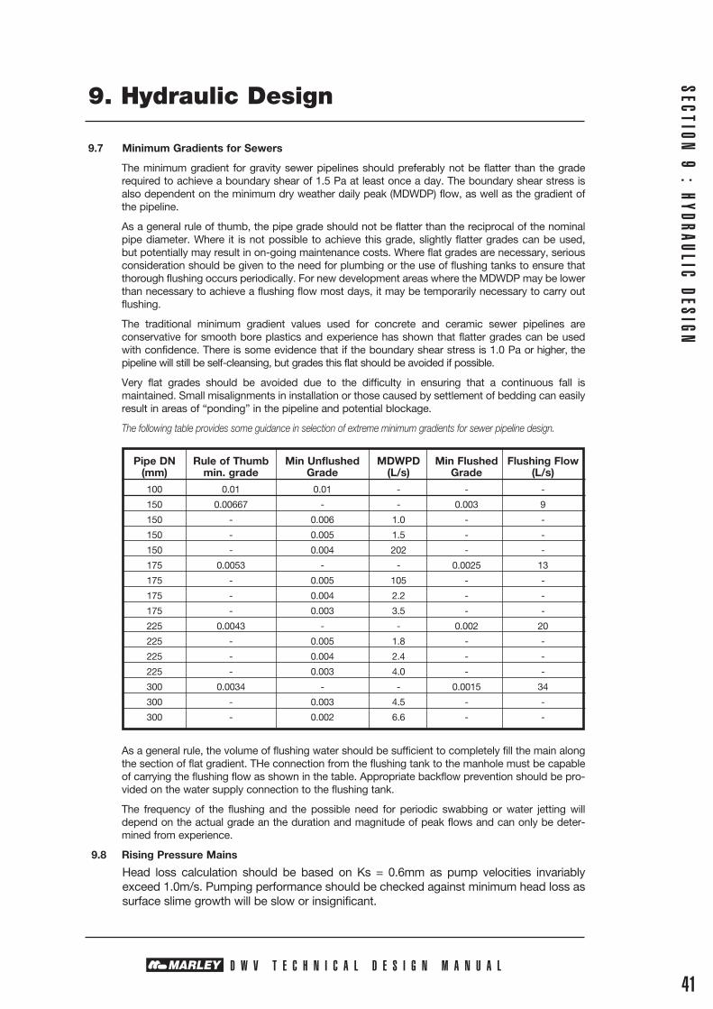
D W V T E C H N I C A L D E S I G N M A N U A L41
9. Hydraulic Design
9.7 Minimum Gradients for Sewers
The minimum gradient for gravity sewer pipelines should preferably not be flatter than the grade required to achieve a boundary shear of 1.5 Pa at least once a day. The boundary shear stress is also dependent on the minimum dry weather daily peak (MDWDP) flow, as well as the gradient of the pipeline.
As a general rule of thumb, the pipe grade should not be flatter than the reciprocal of the nominal pipe diameter. Where it is not possible to achieve this grade, slightly flatter grades can be used, but potentially may result in on-going maintenance costs. Where flat grades are necessary, serious consideration should be given to the need for plumbing or the use of flushing tanks to ensure that thorough flushing occurs periodically. For new development areas where the MDWDP may be lower than necessary to achieve a flushing flow most days, it may be temporarily necessary to carry out flushing.
The traditional minimum gradient values used for concrete and ceramic sewer pipelines are conservative for smooth bore plastics and experience has shown that flatter grades can be used with confidence. There is some evidence that if the boundary shear stress is 1.0 Pa or higher, the pipeline will still be self-cleansing, but grades this flat should be avoided if possible.
Very flat grades should be avoided due to the difficulty in ensuring that a continuous fall is maintained. Small misalignments in installation or those caused by settlement of bedding can easily result in areas of “ponding” in the pipeline and potential blockage.
The following table provides some guidance in selection of extreme minimum gradients for sewer pipeline design.
Pipe DN Rule of Thumb Min Unflushed MDWPD Min Flushed Flushing Flow (mm) min. grade Grade (L/s) Grade (L/s)
100 0.01 0.01 - - -
150 0.00667 - - 0.003 9
150 - 0.006 1.0 - -
150 - 0.005 1.5 - -
150 - 0.004 202 - -
175 0.0053 - - 0.0025 13
175 - 0.005 105 - -
175 - 0.004 2.2 - -
175 - 0.003 3.5 - -
225 0.0043 - - 0.002 20
225 - 0.005 1.8 - -
225 - 0.004 2.4 - -
225 - 0.003 4.0 - -
300 0.0034 - - 0.0015 34
300 - 0.003 4.5 - -
300 - 0.002 6.6 - -
As a general rule, the volume of flushing water should be sufficient to completely fill the main along the section of flat gradient. THe connection from the flushing tank to the manhole must be capable of carrying the flushing flow as shown in the table. Appropriate backflow prevention should be pro-vided on the water supply connection to the flushing tank.
The frequency of the flushing and the possible need for periodic swabbing or water jetting will depend on the actual grade an the duration and magnitude of peak flows and can only be deter-mined from experience.
9.8 Rising Pressure Mains
Head loss calculation should be based on Ks = 0.6mm as pump velocities invariably exceed 1.0m/s. Pumping performance should be checked against minimum head loss as surface slime growth will be slow or insignificant.
SECTION 9 : HYDRAULIC DESIGN

10.1 Deflection Limits
PVC pipe systems are referred to as flexible pipe systems, meaning they can deflect under external load without distress.
This unique ability to deflect under load ensures that when soil and ground movement takes place, (eg. soil consolidation in the first 3 years after installation, earth movement and earthquakes), the PVC pipe line integrity should be maintained.
Marley Optim, Spectrum and Quantum are not designed for pressure pipe performance, but for their stiffness characteristic, and their ability to withstand external soil and live loads.
D W V T E C H N I C A L D E S I G N M A N U A L42
SECT
ION
10
: ST
RUCT
URAL
DES
IGN
PER
FORM
ANCE 10. Structural Design Performance
Marley Impact is designed to have both a pressure performance as a rising or pumping main, with high resistance to notch growth from handling or long term stress from bedding, along with good crush resistance.
Deflection in flexible pipes is resisted by the passive soil support from the soil surrounding the pipe, the trench, the pipe class/rating and the compaction of the bedding material. All must be considered when providing a performance statement on the pipe.
Pipe Deflection = Total Load on a pipe
Pipe Stiffness + Soil Stiffness
Design limits commonly used for deflection of a pipe system are 5% for short term and 7.5% for long-term (50 years). These figures ensure that the flow characteristics of the pipe are not compromised, and that the integrity of all the joints is maintained.
Deflection data collected from studies over the last 30 years show deflection is related to soil movement in the first few years. For the rest of the pipe system’s life, the movement is negligible in any well installed PVC pipe system.
It is assumed that the installers will be competent and install the pipe in line with recommended procedures and to specification.
The following graph is taken from the Recorded Research Data showing clearly old, thinner wall pipe with higher a (51), although adequate, will have greater ovality over time than current lower SDR pipe systems. But with all piping materials the SDR and E modulus of the pipe material must be factored into the deflection design requirements.
While not recommended, there are many PVC pipelines that are performing satisfactorily with deflections up to 20%. Such excessive deflection may be caused by poor compaction of side support or by migration of the bedding material into the surrounding soil.
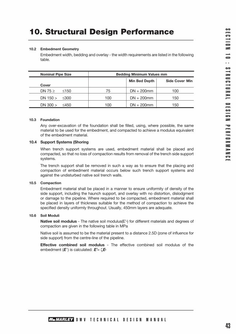
D W V T E C H N I C A L D E S I G N M A N U A L
10. Structural Design Performance
10.2 Embedment Geometry
Embedment width, bedding and overlay - the width requirements are listed in the following table.
Nominal Pipe Size Bedding Minimum Values mm
Min Bed Depth Side Cover Min Cover
DN 75 ≥ ≤150 75 DN + 200mm 100
DN 150 > ≤300 100 DN + 200mm 150
DN 300 > ≤450 100 DN + 200mm 150
10.3 Foundation
Any over-excavation of the foundation shall be filled, using, where possible, the same material to be used for the embedment, and compacted to achieve a modulus equivalent of the embedment material.
10.4 Support Systems (Shoring
When trench support systems are used, embedment material shall be placed and compacted, so that no loss of compaction results from removal of the trench side support systems.
The trench support shall be removed in such a way as to ensure that the placing and compaction of embedment material occurs below such trench support systems and against the undisturbed native soil trench walls.
10.5 Compaction
Embedment material shall be placed in a manner to ensure uniformity of density of the side support, including the haunch support, and overlay with no distortion, dislodgment or damage to the pipeline. Where required to be compacted, embedment material shall be placed in layers of thickness suitable for the method of compaction to achieve the specified density uniformly throughout. Usually, 450mm layers are adequate.
10.6 Soil Moduli
Native soil modulus - The native soil modulus(E’n) for different materials and degrees of compaction are given in the following table in MPa
Native soil is assumed to be the material present to a distance 2.5D (zone of influence for side support) from the centre-line of the pipeline.
Effective combined soil modulus - The effective combined soil modulus of the embedment (E ’) is calculated: E’= ζEe
SECTION 10 : STRUCTURAL DESIGN
PERFORMAN
CE
43

D W V T E C H N I C A L D E S I G N M A N U A L44
SECT
ION
10
: ST
RUCT
URAL
DES
IGN
PER
FORM
ANCE 10. Structural Design Performance
Embedment and Soil - Material Moduli
Native Standard Soil Soil Compaction E ’ MPa
Material Soil Type EN 91% 92% 95% 97% AS1726S
Gravel - single size - MPa 7§ 7§ 10§ 14
Gravel - graded GW 9 5§ 7§ 10§ 20
Sand and coarse-grained soil with less GP, SW, SP & 4 3§ 5§ 7§ 14
than 12% fines GM-GL,GC-SC etc
Coarse-grained soil with more than 12% fines
GM, GC, SC SM & GM-SC, GC-SC
1§ 3§ 5§ 10
Fine-grained soil (LL<50%) with medium to no CM, ML, mixtures plasticity and containing more than 25% ML-CL, CL-CH 2 1§ 3§ 5§ 10 coarse-grained particles & ML-MH
Fine-grained soil (LL<50%) with medium to no CI, CL, ML plasticity and containing less than 25% mixtures ML-CL 1 NR 1 3 7 coarse-grained particles CL-CH & ML-MH
Fine-grained soil (LL>50%) with medium CH, MH & 0.5 NR NR NR NR
to high plasticity CH-MH
§ Value Commonly Achieved in Practise
10.7 Deflection Prediction
Deflection in flexible pipe systems can be predicted using the Modified Spangler Formula to take into account different loading conditions for the specific pipe material performances.
The E Modulus that is used to determine any long-term performance must relate to the specific pipe material class and rating, as the different constructions offer different long term performances.
10.8 Design of PVC Pipelines
The modified Spangler formula can be written as:
▲ y =
D x K x 10-3 (WD + W1)
8 x 10⁻⁶ SDL + 0.061E1
Finished surface
Fe Fe
Trench wall
Trench fill
Embedment zone
Zone of influence for side support(see clause 10.6)
Embankment fillTop of embankment(finished surface)
Embankment zone
(b) Embankment(a) Trench
Foundation Foundation2.5 D 2.5 D 2.5 D 2.5 D
B B
lo
De
lb
Fe

D W V T E C H N I C A L D E S I G N M A N U A L
10. Structural Design Performance
Where: ▲y = change in diameter (mm) W = loads on pipe related to soil (WD) or traffic WD or live loads W1 (kN/m) K = bedding deflection co-efficient is assumed to be 0.1 unless detailed engineering calculations show otherwise D = Diameter at neutral axis of pipe wall E´ = Effect Combination of the soil modulus MPa
SDL = EbL x I x 106
D3
Where: E = Youngs modulus (MPa) for the PVC construction material used in the pipe (refer section 3).
I = Moment of inertia of the pipe wall = t3/12 (mm3) t = wall thickness (mm) r = mean pipe radius (mm) D = Diameter of neutral sizes of pipe wall.
SECTION 10 : STRUCTURAL DESIGN
PERFORMAN
CE
45

D W V T E C H N I C A L D E S I G N M A N U A L46
SECT
ION
10
: ST
RUCT
URAL
DES
IGN
PER
FORM
ANCE 10. Structural Design Performance
10.9 Maximum Buried Depth
Based on 5% Long Term deflection pipe performance for soil and embedment.
10.10 Soil Load
The method of calculating the soil load on a flexible pipe is simply to take it as the weight of the column of soil above the pipe. This is called the “prism load” and is determined from the volume of soil above a metre length of pipe multiplied by the specific weight.
WD = ρgDH Where: W = load per unit length on the pipe (N/m) ρ = soil density (kg/m3) D = pipe diameter (m) H = Cover height (m)
D W V T E C H N I C A L D E S I G N M A N U A L
10. Structural Design Performance
Using the prism load is particularly conservative for flexible pipe laid in narrow trenches, as it ignores the friction effects both of the columns of soil adjacent to the column over the pipe, and against the trench walls. These friction effects significantly reduce the load on the pipe.
Superimposed Live Loads Road Vehicles
For shallow pipes, the live load (W1) becomes significant and can be determined (also refer to AS2566 charts). The average intensity of the design live load at the top of a pipe due to multiple wheel or track vehicle loads, including impact effects, is calculated from the following equation:
W1 =
∑P α L1 L2
Where:
W1 = Vertical design load kPA ∑P = Sum of individual wheel loads kN L1 = Length of the base of the live load (m) measure perpendicular to the direction
of travel of the vehicle at the top. α = Live load impact factor (1.4 - 0.15H but not less than 1.1)
SECTION 10 : STRUCTURAL DESIGN
PERFORMAN
CE
47
NOTES:

48
SECT
ION
11
: CH
EMIC
AL R
ESIS
TAN
CE
D W V T E C H N I C A L D E S I G N M A N U A L
Three different classes of chemical resistance degree are conventionally used in this guide ie:Class 1: HIGH RESISTANCE (corrosion-proof) - all materials belonging to this
class are completely or almost completely corrosion-proof against the conveyed fluid, according to the specified operating conditions.
Class 2: LIMITED RESISTANCE - the materials belonging to this class are partially attacked by the conveyed chemical compound. The average life of the material is therefore shorter, and it is advisable to use a higher safety factor by selecting a higher SN rating pipe.
Class 3: NO RESISTANCE - all material belonging to this class are subject to corrosion by the conveyed fluid and they should therefore not be used.
The absence of any class indication means that no data are available concerning the chemical resistance of the material in respect of the conveyed fluid.
ABBREVIATIONS sat = saturated solution at 20oC, nd = undefined concentration, deb = weak concentration, comm = commercial solution. dil = diluted solution
11. Chemical Resistance
FORMULA CONC % TEMP (oC) PVC PE ACETALDEHYDE CH3CHO 100 25 3 1 60 3 - AQUEOUS SOLUTION 40 25 3 1 60 3 2 ACETIC ACID CH3COOH ≤ 25 25 1 1 60 2 1 30 25 1 1 60 2 1 60 25 1 1 60 2 1 80 25 1 1 60 2
- GLACIAL 100 25 2 1 60 3 2 ACETIC ANHYDRIDE (CH3CO)2O 100 25 3 2 60 3 2 ACETONE CH3COCH3 10 25 3 1 (DIMETHYL KETONE) 60 3 100 25 3 2 60 3 2 ACETOPHENONE CH3COC6H5 nd 25 (ACETYLBENZENE OR 60PHENYL METHYL KETONE) ACRYLONITRILE CH2CHCN technically 25 1(ACRYLONITRILE pure 60 3 1OR VINYL CYANIDE) ADIPIC ACID (CH2CH2CO2H)2 sat. 25 1 1 AQUEOUS SOLUTION 60 2 1 ALLYL ALCOHOL CH2CHCH2OH 96 25 2 1 60 3 2 ALUM AI2(SO4)3K2SO4nH2O dil 25 1 1 AQUEOUS SOLUTION dil 60 2 1 (POTASH ALUM.SOL.) sat. 60 2 1 ALUMINIUM AICI3 all 25 1 1- CHLORIDE 60 1 1 - FLORIDE AIF3 100 25 1 1
60 1 1 - HYDROXIDE AI(OH)3 all 25 1
60 1 - NITRATE AI(NO2)3 nd 25 1
60 1 - SULFATE AI(SO4)3 deb 25 1
60 1 1 sat 25 1 1
60 1 1 AMMONIA NH3 deb 25 1 1 - AQUEOUS SOLUTION 60 2 1 sat 25 1 60 2 - DRY GAS 100 25 1 1
60 1 1 - LIQUID 100 25 2 1 60 3 1 AMMONIUM CH3COONH4 sat 25 - 1 - ACETATE 60 2 1 - CARBONATE (NH4)2CO3 all 25 1 1 60 2 1
FORMULA CONC % TEMP (oC) PVC PE - FLUORIDE NH4F 25 25 1 1 60 2 1
- HYDROXIDE NH4OH 28 25 - 1 60 2 1
- NITRATE NH4NO3 sat 25 1 1 60 1 1
- PHOSPHATE DIBASIC NH4(HPO4)2 all 25 1 1 60 1 1
- PHOSPHAT META (NH4)4P4O12 all 25 1 60 1
- PHOSPHATE TRI (NH4)2HPO4 all 25 1 60 1
- PERSULFATE (NH4)2S2O8 all 25 1 60 1
- SULFIDE (NH4)2S deb 25 1 1 60 2 1 sat 25 1 1 60 1 1
- SULFHYDRATE NH4OHSO4 dil 25 1 1 60 2 1 sat 25 1 1 60 1 1 AMYLACETATE CH3CO2CH2(CH2)3CH3 100 25 3 1 (PENTYL ACETATE) 60 3 2 AMYLALCOHOL CH3(CH2)3CH2OH nd 25 1 1 60 2 1 ALNILINE C6H5HN2 all 25 3 2 (PHENYLAMINE 60 3 2
OR AMINOBENZENE)- CHLORHYDRATE CH6H5NH2HCI nd 25 2 2 (ANILINE HYDROCHLORIDE) 60 3 2 ANTIMONY SbCI3 100 25 1 1 - TRICHLORIDE 60 1 1 ANTHRAQUINONE suspension 25 1 1 (SULFONIC ACID) 60 2 - AQUA REGIA HCI+HNO3 100 25 2 3 60 2 3ARSENIC ACID H3ASO4 deb 25 1 1 60 2 1 80 25 1 1 60 2 1BARIUM BACO3 all 25 1 1CARBONATE 60 1 1 - CHLORIDE BaCI2 10 25 1 1 60 1 1
- HYDROXIDE Ba(OH)2 all 25 1 1 60 1 1
- SULFATE BaSO4 nb 25 1 1 60 1 1
- SULFIDE BaS sat 25 1 60 1
BEER comm 25 1 1 60 1 BENZALDEHYDE C6H5CHO nd 25 3 2 60 3 2
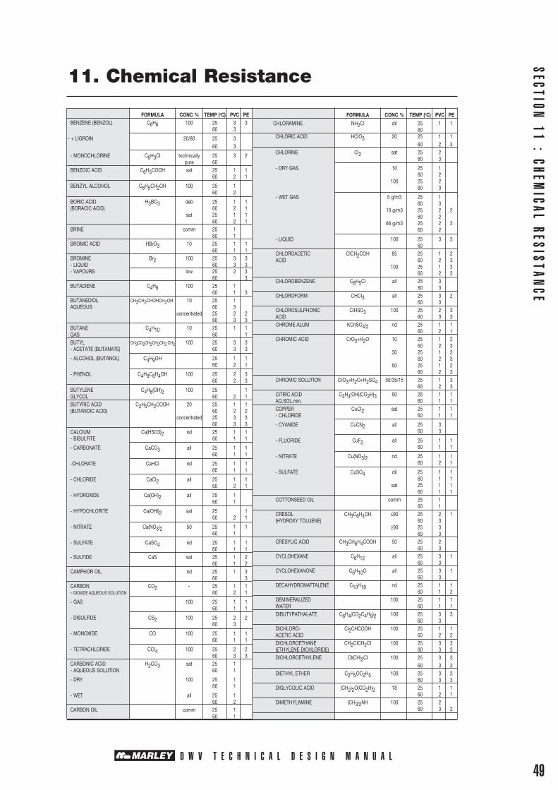
D W V T E C H N I C A L D E S I G N M A N U A L
11. Chemical Resistance
SECTION 11 : CHEM
ICAL RESISTANCE
49
FORMULA CONC % TEMP (oC) PVC PE BENZENE (BENZOL) C6H6 100 25 3 3 60 3
- + LIGROIN 20/80 25 3 60 3
- MONOCHLORINE C6H3CI technically 25 3 2 pure 60 BENZOIC ACID C6H5COOH sat 25 1 1 60 2 1
BENZYL ALCOHOL C6H5CH2OH 100 25 1 60 2
BORIC ACID H3BO3 deb 25 1 1 (BORACIC ACID) 60 2 1 sat 25 1 1 60 2 1 BRINE comm 25 1 60 1 BROMIC ACID HBrO3 10 25 1 1 60 1 1 BROMINE Br2 100 25 3 3 - LIQUID 60 3 3 - VAPOURS low 25 2 3 60 3 BUTADIENE C4H6 100 25 1 60 1 3 BUTANEDIOL CH3CH2CHOHCH2OH 10 25 1 AQUEOUS 60 3 concentrated 25 2 2 60 3 3 BUTANE C4H10 10 25 1 1 GAS 60 1 BUTYL CH3CO2CH2CH2CH2 CH3 100 25 3 3 - ACETATE (BUTANATE) 60 3 3
- ALCOHOL (BUTANOL) C4H9OH 25 1 1 60 2 1
- PHENOL C4H9C6H4OH 100 25 2 3 60 2 3
BUTYLENE C4H6(OH)2 100 25 1 GLYCOL 60 2 1 BUTYRIC ACID C2H5CH2COOH 20 25 1 1 (BUTANOIC ACID) 60 2 2 concentrated 25 3 3 60 3 3 CALCIUM Ca(HSO3)2 nd 25 1 1 - BISULFITE 60 1 1
- CARBONATE CaCO3 all 25 1 1 60 1 1
-CHLORATE CaHCI nd 25 1 1 60 1 1
- CHLORIDE CaCl2 all 25 1 1 60 2 1
- HYDROXIDE Ca(OH)2 all 25 1 60 1
- HYPOCHLORITE Ca(OHI)2 sat 25 1 60 2 1
- NITRATE Ca(NO3)2 50 25 1 1 60 1
- SULFATE CaSO4 nd 25 1 1 60 1 1 - SULFIDE CaS sat 25 1 2
60 1 2 CAMPHOR OIL nd 25 1 3 60 3 CARBON CO2 - 25 1 1 - DIOXIDE AQUEOUS SOLUTION 60 2 1
- GAS 100 25 1 1 60 1 1
- DISULFIDE CS2 100 25 2 2 60 3
- MONOXIDE CO 100 25 1 1 60 1 1
- TETRACHLORIDE CCI4 100 25 2 2 60 3 3 CARBONIC ACID H2CO3 sat 25 1 - AQUEOUS SOLUTION 60 1
- DRY 100 25 1 60 1
- WET all 25 1 60 2 CARBON OIL comm 25 1 60 1
FORMULA CONC % TEMP (oC) PVC PE
CHLORAMINE NH2Cl dil 25 1 1 60 CHLORIC ACID HCIO3 20 25 1 1 60 2 3 CHLORINE CI2 sat 25 2 60 3
- DRY GAS 10 25 1 60 2 100 25 2 60 3
- WET GAS 5 g/m3 25 1 60 3 10 g/m3 25 2 2 60 2 66 g/m3 25 2 2 60 2
- LIQUID 100 25 3 3 60 CHLOROACETIC CICH2COH 85 25 1 2 ACID 60 2 3 100 25 1 3 60 2 3 CHLOROBENZENE C6H5CI all 25 3 60 3 CHLOROFORM CHCI3 all 25 3 2 60 3 CHLOROSULPHONIC CIHSO3 100 25 2 3 ACID 60 3 3 CHROME ALUM KCr(SO4)2 nd 25 1 1 60 2 1 CHROMIC ACID CrO3+H2O 10 25 1 2 60 2 3 30 25 1 2 60 2 3 50 25 1 2 60 2 3 CHROMIC SOLUTION CrO3+H2O+H2SO4 50/35/15 25 1 3 60 2 3 CITRIC ACID C3H4(OH)(CO2H)3 50 25 1 1 AQ.SOL.min. 60 1 1 COPPER CuCI2 sat 25 1 1 - CHLORIDE 60 1 1
- CYANIDE CuCN2 all 25 3 60 3
- FLUORIDE CuF2 all 25 1 1 60 1 1
- NITRATE Cu(NO3)2 nd 25 1 1 60 2 1
- SULFATE CuSO4 dil 25 1 1 60 1 1 sat 25 1 1 60 1 1 COTTONSEED OIL comm 25 1 60 1 CRESOL CH3C6H4OH ≤90 25 2 1 (HYDROXY TOLUENE) 60 3 ≥90 25 3 60 3 CRESYLIC ACID CH3CH6H4COOH 50 25 2 60 3 CYCLOHEXANE C6H12 all 25 3 1 60 3 CYCLOHEXANONE C6H10O all 25 3 1 60 3 DECAHYDRONAFTALENE C10H18 nd 25 1 1 60 1 2 DEMINERALIZED 100 25 1 1 WATER 60 1 1 DIBUTYPATHALATE C6H4(CO2C4H9)2 100 25 3 3 60 3 DICHLORO- Cl2CHCOOH 100 25 1 1 ACETIC ACID 60 2 2 DICHLOROETHANE CH2CICH2CI 100 25 3 3 (ETHYLENE DICHLORIDE) 60 3 3 DICHLOROETHYLENE CI(CH)2CI 100 25 3 3 60 3 3 DIETHYL ETHER C2H5OC2H5 100 25 3 3 60 3 3 DIGLYCOLIC ACID (CH2)2O(CO2H)2 18 25 1 1 60 2 1 DIMETHYLAMINE (CH3)2NH 100 25 2 60 3 2

D W V T E C H N I C A L D E S I G N M A N U A L50
SECT
ION
11
: CH
EMIC
AL R
ESIS
TAN
CE 11. Chemical Resistance
FORMULA CONC % TEMP (oC) PVC PE
DIOCTYLPHTHALATE all 25 3 1 60 3 2 DISTILLED WATER 100 25 1 1 60 1 1 DRINKING WATER 100 25 1 1 60 1 1 ETHERS all 25 3 60 3 ETHYL CH3CO2C2H5 100 25 3 1 - ACETATE (ACETIC ETHER) 60 3 3
- ALCOHOL CH3CH2OH nd 25 1 1 60 2 2 (ETHANOL) CH3CH2CI all 25 3 2
- CHLORIDE 60 3
- ETHER CH3CH2OCH2CH3 all 25 3 60 3 ETHYLENE CICH2CH2OH 100 25 3
- CHLOROHYDRIN 60 3 - GLYCOL HOCH2CH2OH comm 25 1 1
(ETHANEDIOL OR GLYCOL) 60 1 3 FATTY ACIDS nd 25 1 60 1 FERRIC FeCI3 10 25 1
- CHLORIDE 60 2 sat 25 1 1
60 1 1 - NITRATE Fe(NO3)3 nd 25 1 1
60 1 1 - DEXTRINE (BRITISH GUM C6H12OCH2O nd 25 1 1
OR STARCH GUM) 60 2 1 - SULFATE Fe(SO4)3 nd 25 1 1 60 1 1 FERROUS FeCI2 sat 25 1 1
- CHLORIDE 60 1 1 - SULFATE FeSO4 nd 25 1 1
60 1 1 FERTILIZER ≤ 10 25 1 1 60 1 1 sat 25 1 1 60 1 1 FLUORINE GAS F2 100 25 2 2 DRY 60 3 3 FLUROSILICIC ACID H2SiF6 32 25 1 1 60 1 1 FORMALDEHYDE HCOH - 25 1 1 60 2 1 FORMIC ACID HCOOH 50 25 1 1 60 2 1 100 25 1 1 60 3 1 FRUIT PULP AND JUICE comm 25 1 1 60 1 FUEL OIL 100 25 1 60 1 comm 25 1 - 60 1 2 FURFUROLE C5H3OCH2OH nd 25 3 2
ALCOHOL 60 3 2 GAS EXHAUST all 25 1 - ACID 60 1
- WITH NITROUS traces 25 1 1 - VAPOURS 60 1 1 GAS PHOSGENE CICOCI 100 25 1 2 60 2 2 GELATINE 100 25 1 1 60 1 - GLUCOSE C6H12O6 all 25 1 1
(DEXTROSE) 60 2 1 GLYCERINE HOCH2CHOHCH2OH all 25 1 1 AQ.SOL(GLYCEROL) 60 1 1 GLYCOGLUE 10 25 1 1 AQUEOUS 60 1 1 GLYCOLIC ACID HOCH2COOH 37 25 1 1 60 1 1 HEPTANE C7H16 100 25 1 1 60 2 3 HEXANE C6H14 100 25 1 1
60 2 2 HYDROBROMIC ACID HBr ≤10 25 1 1 60 2 1 48 25 1 1 60 2 1
FORMULA CONC % TEMP (oC) PVC PEHYDROCHLORIC ACID HCI ≤25 25 1 1 (MURIATIC ACID) 60 2 1 ≤ 37 25 1 1 60 1 2 HYDROCYANIC ACID HCN deb 25 1 1 (PRUSSIC ACID OR 60 1 1 HYDROGEN CYANIDE)HYDROFLUORIC ACID HF 10 25 1 1 60 2 1 HYDROGEN H2 all 25 60 HYDROGEN H2O2 30 25 1 1 - PEROXIDE (BLEACH) 60 1 1 50 25 1 2 60 1 -
- SULFIDE DRY sat 25 1 1 60 2 1
- SULFIDE WET sat 25 1 1 60 2 1 HYDROSUPHITE ≤10 25 1 60 2 HYDROXYLAMINE (H2NOH)2H2SO4 12 25 1 1
SULPHATE 60 1 ILLUMINATING 100 25 1 1 GAS 60 IODINE I2 3 25 2 - DRY AND WET 60 3
- TINCTURE ≤3 25 2 2 60 3 3 ISOCTANE C8H18 100 25 1 2 60 ISO-OCTANE (CH3)3CCH2(CH3)2 ISOPROPYL (CH3)2CHOCH(CH3)2 100 25 2 2 -ETHER 60 3 3
- ALCOHOL (CH3)2CHOH 100 25
(ISOPROPANOL) 60 2 LACTIC ACID CH3COHCOOH ≤28 25 1 1 60 2 1 LANOLINE nd 25 1 60 2 1 LEAD ACETATE Pb(CH3COO)2 sat 25 1 1 60 1 - LINSEED OIL comm 25 1 60 2 2 LUBRICATING OILS comm 25 1 3 60 1 MAGNESIUM MgCO3 all 25 1 - CARBONATE 60 1
- CHLORIDE MgCI2 sat 25 1 1 60 1 1
- HYDROXIDE Mg(OH)2 all 25 1 60 1
-NITRATE MgNO3 nd 25 1 1 60 1 1
- SULFATE MgSO4 dil 25 1 1 60 1 1 sat 25 1 1 60 1 1 MALEIC ACID COOHCHCHCOOH nd 25 1 1 60 1 1 MALIC ACID CH2CHOH(COOH)2 nd 25 1 1 (HYDROXYSUCCINIC ACID) 60 - - MERCURIC HgCI2 sat 25 1 1 - CHLORIDE 60 1 1 - CYANIDE HgCN2 all 25 1 60 1
MERCUROUS HgNO3 nd 25 1 1 NITRATE 60 1 1 MERCURY Hg 100 25 1 1 60 2 1 METHYL CH3COOCH3 100 25 - - - ACETATE 60 - -
- ALCOHOL (METHANOL CH3OH nd 25 1 OR WOODSPIRIT) 60 1 1
- BROMIDE CH3Br 100 25 3 3 (BROMOMETHANE) 60
- CHORIDE CH3CI 100 25 3 1 (CHLOROMETHANE) 60 3
- ETHYLKETONE CH3COCH2CH3 all 25 3 1 60 3 2 METHYLAMINE CH3NH2 32 25 2 1 60 3 2

D W V T E C H N I C A L D E S I G N M A N U A L
11. Chemical Resistance
SECTION 11 : CHEM
ICAL RESISTANCE
51
FORMULA CONC % TEMP (oC) PVC PE METHYLENE CHLORIDE CH2CI2 100 25 3 3(DICHLOROMETHANE) 60 3 METHYL SULPHORIC ACID CH3COOSO4 50 25 1 2 60 2 2 100 25 1 3 60 2 3 MILK 100 25 1 1 60 1 MINERAL ACIDOULOUS nd 25 1 1 WATER 60 1 1 MOLASSES comm 25 1 1 60 2 2 NAPHTA 100 25 2 2 60 3 3 NAPHTALINE 100 25 1 1 60 2 NICKEL NiCI3 all 25 1 1 - CHLORIDE 60 1 1
- NITRATE Ni(NO3)2 nd 25 1 1 60 1 1
- SULFATE NiSO4 dil 25 1 1 60 1 2 sat 25 1 1 60 1 1 NITRIC ACID HNO3 anhydrous 25 3 60 3 20 25 1 1 60 2 2 40 25 1 - 60 1 2 60 25 1 3 60 2 3 98 25 3 3 60 3 3 NITROBENZENE C6H5NO2 all 25 3 60 3 2 OLEIC ACID C8H17CHCH(CH2)7CO2H comm 25 1 - 60 1 2 OLEUM (FUMING SULPHURIC) H2S2O7 nd 25 3 ACID OR PYROSULPHURIC ACID) 60 3 3
- VAPOURS low 25 3 60 3 high 25 3 60 3 OLIVE OIL comm 25 60 2 3 OXALIC ACID HO2CCO2H 10 25 1 1 60 2 1 sat 25 1 1 60 1 1 OXYGEN O2 all 25 1 1 60 1 2 OZONE O3 nd 25 1 2
60 2 3 PALMITIC ACID CH3(CH2)14COOH 10 25 1 - 60 1 70 25 1 - 60 1 PARAFFIN (ALKANE) nd 25 60 2 2
- EMULSION comm 25 1 2 60 1 2
- OIL (KEROSENE) nd 25 1 60 1 PERCHLORIC HCIO4 100 25 1 1 ACID 60 2 1 70 25 1 1 60 2 2 PETROL 100 25 1
- REFINED 60 1 - UNREFINED 100 25 1 60 1 PHENOL C6H5OH 1 25 1 1
- AQUEOUS SOLUTION 60
(CARBOLIC ACID) ≤90 25 2 1 60 3
PHENYL HYDRAZINE C6H5NHNH2 all 25 3 2 60 3 2 - CHLORHYDRATE C6H5NHNH3CI sat 25 1 1
60 3 3 PHOSPHORIC H3PO4 ≤ 25 25 1 1 - ACID 60 2 1 ≤50 25 1 1 60
FORMULA CONC % TEMP (oC) PVC PE ≤85 25 1 1 60 1 2 - ANHYDRIDE P2O5 nd 25 1 1 60 2 1 PHOSPHORUS PCI3 100 25 3 1 TRICHLORIDE 60 3 PHOTOGRAPHIC comm 25 1 - DEVELOPER 60 1
- EMULSION comm 25 1 1 60 1 PHTHALIC ACID C6H4(CO2H)2 50 25 - 1 60 3 1 PICRIC ACID HOC6H2(NO2)3 1 25 1 1 60 1 -
(2,4,6 TRINITROPENOL) ≥1 25 3 1 60 3 POTASSIUM K2Cr2O7 40 25 1 1 - BICHROMATE (POTASSIUM 60 1 HYDROGENCARBONATE)
- BORATE K3BO3 sat 25 1 60 2
- BROMATE KBrO3 nd 25 1 60 2
- BROMIDE KBr sat 25 1 1 60 1
- CARBONATE (POTASH) K2CO3 sat 25 1 1 60 1 1
- CHROLIDE KCI sat 25 1 1 (POTASSIUM MURIATE) 60 1 1
- CHROMATE K2CrO4 40 25 1 1 60 1 1
- CYANIDE KCN sat 25 1 1
60 1 1
- FERROCYANIDE K4Fe(CN)63H2O 100 25 1 1 60 1 1
- FLUORIDE KF sat 25 1 60 1
- HYDROXIDE KOH ≤60 25 1 1 (CAUSTIC POTASH) 60 2 1
- NITRATE KNO3 sat 25 1 1 (NITRE, SALTPETRE) 60 1 1 - PERBORATE KBO3 all 25 1 60 1
- PERBORATE KBO3 all 25 1 60
- PERMANGANATE KMnO4 10 25 1 1 (PERMANGANATE OF POTASH) 60 1 1
- PERSULFATE K2S2O8 nd 25 1 1 60 2 1
- SULFATE K2SO4 sat 25 1 1 60 2 1 PROPANE C3H8 100 25 1 1 - GAS 60
- LIQUID 100 25 1 2 60 PROPYL ALCOHOL C3H7OH 100 25 1 1
(PROPANOL) 60 2 1 PYRIDINE CH(CHCH)2N nd 25 3 1 60 3 2 RAIN WATER 100 25 1 1 60 1 1
SEA WATER 100 25 1 1 60 1 1 SILICIC ACID H2SiO3 all 25 1 1 60 1 1 SILICONE OIL nd 25 1 1 60 3 2 SILVER AgCN all 25 1 - CYANIDE 60 1
- NITRATE AgNO3 nd 25 1 1 60 2 1
- PLATING SOLUTION comm 25 1 60 1 SOAP high 25 1 - AQUEOUS SOLUTION 60 2 SODIC LYE ≤60 25 1 60 1 SODIUM CH3COONa 100 25 1 1 - ACETATE 60 1 1

D W V T E C H N I C A L D E S I G N M A N U A L
SECT
ION
11
: CH
EMIC
AL R
ESIS
TAN
CE
52
11. Chemical Resistance
FORMULA CONC % TEMP (oC) PVC PE- BICARBONATE (SODIUM NaHCO3 nd 25 1 1 HYDROGEN CARBONATE) 60 1 1
- BISULFITE NaHSO3 100 25 1 1 60 1 1
- BROMIDE NaBr sat 25 1 60 1
- CARBONATE Na2CO3 sat 25 1 1 60 1 1
- CHLORATE NaCIO3 nd 25 1 1 60 2 1
- CHLORIDE NaCI dil 25 1 1 60 2 1 sat 25 1 1 60 1 1
- CYANIDE NaCN all 25 1 60 1
- FERROCYANIDE Na4Fe(CN)6 sat 25 1 1 60 1 1
- FLUORIDE NaF all 25 1 1 60 1 1
- HYDROXIDE NaOH 60 25 1 1 60 1 1 - HYPOCHLORITE NaOCI deb 25 1 1 60 2
- HYPOSULFITE Na2S3O3 nd 25 1 60 1
- NITRATE NaNO3 nd 25 1 1 60 1 1
- PERBORATE NaBO3H2O all 25 1 60 1
- PHOSPHATE di Na2HPO4 all 25 1 60 1
- PHOSPHATE tri Na3PO4 all 25 1 1 60 1 1
- SULPHATE Na2SO4 dil 25 1 60 1 sat 25 1 1 60 1 1
- SULFIDE Na2S dil 25 1 1 60 2 1
sat 25 1 1 60 1 1
- SULFITE NaSO3 sat 25 1 60 1 STANNIC CHLORIDE SnCI4 sat 25 1 1 60 1 1 STANNOUS CHLORIDE SnCI2 dil 25 1 1 60 1 1 STEARIC ACID CH3(CH2)16CO2H 100 25 1 60 1 2 SUGAR SYRUP high 25 1 1 60 2 1 SULPHUR S 100 25 1 60 2
- DIOXIDE AQUEOUS SO2 sat 25 1 1 60 2 - DIOXIDE DRY all 25 1 1 60 1 1 - DIOXIDE LIQUID 100 25 2 1 60 3 2
- TRIOXIDE SO3 100 25 2 3 60 2 3 SULPHURIC ACID H2SO4 ≤ 10 25 1 1 60 1 1 ≤75 25 1 1 60 2 2 ≤90 25 1 2 60 2 2 ≤96 25 2 2
FORMULA CONC % TEMP (oC) PVC PE 60 3 2- FUMING (OLEUM) all 25 2 60 3
- NITRIC H2SO4+HNO3+H2O 48/49/3 25 1 3 AQUEOUS SOLUTION 60 2 3 50/50/0 25 2 3 60 3 3 10/20/70 25 1 2 60 1 2 TALLOW EMULSION comm 25 1 1 60 1 2 TANNIC ACID C14H10O9 10 25 1 1 60 1 1 TARTARIC ACID HOOC(CHOH)2COOH all 25 1 1 60 2 1 TETRACHLORO CHCI2CHCI2 nd 25 3 2 - ETHANE 60 3 3 - ETHYLENE CCI2CCI2 nd 25 3 2 (PERCHLOROETHYLENE) 60 3 3 TETRAETHYLLEAD Pb(C2H5)4 100 25 1 1 60 2 TETRAHYDROFURAN C4H8O all 25 3 2
60 3 3 THIONYL CHLORIDE SOCI3 - 25 3 3 60 THIOPHENE C4H4S 100 25 3 2 60 3 2 TOLUENE C6H5CH3 100 25 3 2
60 3 3 TRANSFORMER OIL nd 25 1 1 60 2 2 TRICHLORO- CCI3COOH ≤50 25 1 1
ACETIC ACID 60 3 2 TRICHLOROETHYLENE CI2CCHCI 100 25 3 2 60 3 2 TRIETHANOLAMINE N(CH2CH2OH)2 100 25 2 1 60 3 TURPENTINE 100 25 2 2 60 2 3 UREA CO(NH2)2 ≤ 10 25 1 1 AQUEOUS SOLUTION 60 2 1 33 25 1 1 60 2 1 URINE nd 25 1 1 60 2 1 URIC ACID C5H4N4O3 10 25 1 60 2 VASELINE OIL 100 25 1 1 60 3 2 VINYL ACETATE CH3CO2CHCH2 100 25 3 60 3 WHISKEY comm 25 1 60 1 WINES comm 25 1 1 60 1 WINE VINEGAR comm 25 1 1 60 2 1 ZINC ZnCI2 dil 25 1 1 - CHLORIDE 60 1 1 sat 25 1 1 60
- CHROMATE ZnCrO4 all 25 1 60 1
- CYANIDE Zn(CN)2 all 25 1 60
- NITRATE Zn(NO3)2 nd 25 1 60 1 - SULFATE ZnSO4 dil 25 1 1 60 1 1 sat 25 1 1 60 1 1


AUCKLANDMahia Road, Manurewa, Private Bag 802 ManurewaSales Department: Telephone 09 279 2777Direct Fax 09 279 2778 Freefax 0800 652 621Head Office: Telephone 09 279 2799 Fax 09 279 2798Sales Hotline: 0800 222 922
CHRISTCHURCHShands Road, Hornby, PO Box 16233 ChristchurchSales Hotline: 0800 222 922For more information call free 0800 MARLEY (0800 627 539)
DISCLAIMERThis technical manual has been compiled by Marley New Zealand Limited (“The Company”) to promote better understanding of the technical aspects of the Company’s products to assist users in obtaining from them the best possible performance.The technical manual is supplied subject to acknowledgment of the following conditions:The technical manual is protected by Copyright and may not be copied or reproduced in any form or by any means in whole or in part without prior consent in writing by the Company.Product specifications, usage data and advisory information may change from time to time with advances in research and field experience. The Company reserves the right to make such changes at any time without notice.Correct usage of the Company’s products involve engineering judgements which cannot be properly made without full knowledge of all the conditions pertaining to each specific installation. The Company expressly disclaims all and any liability to any person whether supplied with this publication or not in respect of anything and of the consequences of anything done or omitted to be done by any such person in reliance whether whole or partial upon the whole or any part of the contents of this publication.No offer to trade, nor any conditions of trading, are expressed or implied by the issue or content of this manual.Nothing herein shall override the Company’s Conditions of Sale, which may be obtained from the Registered Office or any Sales Office of the Company.This technical manual is and shall remain the property of the Company, and shall be surrendered on demand to the Company.
ENER
GI 1
0186
8