Embed Size (px)
Citation preview

1
Maritime (Part 80) and Aviation (Part Maritime (Part 80) and Aviation (Part 87) Radio Services 87) Radio Services -- Details Details
October 2005October 2005TCB WorkshopTCB Workshop
Andy Andy LeimerLeimerEquipment Authorization BranchEquipment Authorization Branch
Federal Communications CommissionOffice of Engineering and Technology
Laboratory Division

2
October 2005 TCB Workshop 2
Maritime ServicesMaritime ServicesGMDSS OverviewGMDSS Overview
The Global Maritime Distress and Safety System (GMDSS) is an international system which uses terrestrial and satellite technology and ship-board radio-systems to ensure rapid, automated, alerting of shore based communication and rescue authorities, in addition to ships in the immediate vicinity, in the event of a marine distress.GMDSS is the general “umbrella” that cover many Maritime radio services
Global maritime distress and safety system (GMDSS). An International Maritime Organization (IMO) worldwide coordinated maritime distress system designed to provide the rapid transfer of distress messages from vessels in distress to units best suited for giving or coordinating assistance. The system includes standardized equipment and operational procedures, unique identifers for each station, and the integrated use of frequency bands and radio systems to ensure the transmission and reception of distress and safety calls and messages at short, medium and long ranges.
MF (including DSC) – 2 MHz BandHF (including DSC and telex) – 4, 6, 12,16, 18, 22, and 25 MHz BandsVHF (including DSC) – 156 to 162 MHz

3
October 2005 TCB Workshop 3
Maritime ServicesMaritime ServicesGMDSS Overview (Cont.)GMDSS Overview (Cont.)
GMDSS Geographic Configuration
Applies to cargo vessels >300 gross tons & passenger ships carrying more than 12 passengers when traveling on international waters or in the open sea.Depends on the sea area of which the ship will trade:
http://www.navcen.uscg.gov/marcomms/gmdss/area.htm
Sea area A1 is within VHF range of a coast stationSea area A2 is within MF range of a coast stationSea area A3 is within Inmarsat Satellite System coverageSea area A4 is world-wide and within HF range of a coast station (Including the Polar Regions)

4
October 2005 TCB Workshop 4
Maritime ServicesMaritime ServicesDigital Selective Calling (DSC) OverviewDigital Selective Calling (DSC) Overview
Replacement for the radiotelephone and radiotelegraph (Morse) alarm signal Information transmitted:– the priority of the call - DISTRESS, URGENCY, SAFETY or
ROUTINE; – the address - ie: all ships or a single ship/station – the identification of the ship in distress – the position of the ship in distress– the nature of the distress
MF/HF DSC Distress and Safety Channels:2187.5, 4207.5, 6312.0, 8414.5, 12577.0, and 16804.5 kHz
VHF DSC Distress and Safety Channel:Marine channel 70 (156.525 MHz)
DSC Classifications:http://www.navcen.uscg.gov/marcomms/gmdss/dsc.htm

5
October 2005 TCB Workshop 5
Maritime ServicesMaritime ServicesVHF Channel InformationVHF Channel Information
156 to 162 MHz – channelized radio service (assigned channel frequencies)– A Channels: ship frequencies– B Channels: shore frequencies
http://www.navcen.uscg.gov/marcomms/vhf.htmChannels 2, 4, 60, and 62 cannot be used for transmission in US waters- User’s Manual must make this clear
R&O (FCC 04-3) redesignates Channels 75 and 76 for communications related to port operations, and establish requirements for equipment to operate on the channels with reduced carrier power http://hraunfoss.fcc.gov/edocs_public/attachmatch/FCC-04-3A1.pdf
Second R&O, Sixth R&O, and Second FNPRM (FCC 04-3)
redesignate Channels 75 and 76 for communications related to port operations, and establish requirements for equipment to operate on the channels with reduced carrier power; establish a new emission mask in Part 80 to accommodate a wide range of data services

6
October 2005 TCB Workshop 6
Maritime ServicesMaritime ServicesVHF User’s Manual VHF User’s Manual -- Frequency TableFrequency Table

7
October 2005 TCB Workshop 7
Maritime ServicesMaritime ServicesVHF Applicable RulesVHF Applicable Rules
GMDSS – Part 80 Subpart WGMDSS Equipment must meet the requirements of 80.1101(c)(2)Non-Compulsory or voluntary equipment must meet the requirements of 80.225(a)WARNING: DSC is permitted in VHF handheld radios but it must also meet 80.225(a). Paragraph 80.225(a) requires that DSC equipment installed in coast or ship stations must meet either the requirements of ITU-R M.493 or RTCM Paper 56-95/SC101-STD. Contact the FCC.DSC typically not in handhelds since the requirements are hard to meet
Technical StandardsDC Voltage & Current into Final Device 2.1033(C)(8)RF Output Power 2.1046 (Typically conducted power)Modulation Characteristics (Audio Roll-off) 2.1047 & 80.213Modulation Characteristics (Audio Frequency Response) 2.1047Modulation Characteristics (Modulation Limiting) 2.1047Occupied Bandwidth 2.1049(c)(1) & 80.211Spurious & Harmonic Emission at Antenna Terminal 2.1051Field Strength of Spurious & Harmonic Radiation 2.1053Frequency Stability (Temperature) 2.1055 & 80.209Frequency Stability (Voltage) 2.1055 & 80.209Receiver radiated spurious emissions 80.217(b)DC Voltage & Current into Final Device 2.1033(C)(8)
§ 80.207 Classes of emissionupdated chart of Part 80 emissions designators
§ 80.213 Modulation requirements156-162 and 216-220 MHz bands freq. deviation cannot exceed +/- 5 kHz
§ 80.215 Transmitter powernon portable ship station in the 156-162 MHz band must be between 8 and 25 Watts
§ 80.275 AIS US Coast Guardapproval requirements defined
§ 80.373 Private communications frequenciesupdated frequency use table for 156–162 MHz Band

8
October 2005 TCB Workshop 8
Maritime ServicesMaritime ServicesVHF Applicable Rules (Cont.)VHF Applicable Rules (Cont.)
Section 80.1101(b)…must be tested in accordance with the applicable testing standards listedSection 80.1101(c)(2) – lists applicable standards– IMO Resolution A.803(19) Performance Standards for
Shipborne VHF Radio Installations Capable of Voice Communication and Digital Selective Calling
– ITU-R Recommendation M.493–10 Digital Selective-calling System for Use in the Maritime Mobile Service
– ITU-R Recommendation M.541-8 Operational Procedures for the use of Digital Selective-Calling Equipment in the Maritime Mobile Service

9
October 2005 TCB Workshop 9
Maritime ServicesMaritime ServicesVHF Applicable StandardsVHF Applicable Standards
RTCM Paper 56-95/SC101-STD– RTCM Recommended Minimum Standards for DSC Equipment
Providing Minimum Distress and Safety Capability, Version 1.0 –defines minimum functions for DSC transceivers used in the US
– Paper Only ($10)https://ssl29.pair.com/dmarkle/puborder.php?show=2
ITU-R M.541-9 Operational procedures for the use of digital selective-calling equipment in the maritime mobile servicehttp://www.gmdss.com.au/ITU%20DSC%20op%20spec.pdfITU-R M.493-11Digital selective-calling system for use in the maritime mobile servicehttp://www.gmdss.com.au/ITU%20DSC%20tech%20spec.pdfITU Radiocommunication Sector – standards, updates & newsSubscription Services (Electronic or paper)http://www.itu.int/ITU-R/
(4) MF/HF radio equipment: (i) IMO Resolution A.806(19), “Performance Standards for ShipborneMF/HF Radio Installations Capable of Voice Communication, Narrow-Band Direct Printing and Digital Selective Calling,” with Annex, adopted 23 November 1995, as amended by IMO Resolution MSC.68(68), “Adoption of Amendments to Performance Standards for ShipborneRadiocommunication Equipment,” GMDSS terrestrial communications—1.3(c), adopted 6 June 1997.(ii) ITU-R Recommendation M.493–10, “Digital Selective-calling System for Use in the Maritime Mobile Service,” with Annexes 1 and 2, 2000, and ITU-R Recommendation M.541–8, “Operational Procedures for the Use of Digital Selective-Calling Equipment in the Maritime Mobile Service,” with Annexes, 1997.(iii) ITU-R Recommendation M.625–3, “Direct-Printing Telegraph Equipment Employing Automatic Identification in the Maritime Mobile Service,” with Annex, 1995, ITU-R Recommendation M.493–10, “Digital Selective-calling System for Use in the Maritime Mobile Service,” with Annexes 1 and 2, 2000. Equipment may conform to ITU-R Recommendation M.476–5, “Direct-Printing Telegraph Equipment in the Maritime Mobile Service,” with Annex, 1995, in lieu of ITU-R Recommendation M.625–3 with Annex, 1995, where such equipment was installed on ships prior to February 1, 1993.(iv) IMO Resolution A.700(17), “Performance Standards for Narrow-band Direct-printing Telegraph Equipment for the Reception of Navigational and Meteorological Warnings and Urgent Information to Ships (MSI) by HF,” adopted 6 November 1991.

10
October 2005 TCB Workshop 10
Maritime ServicesMaritime ServicesVHF Equipment AuthorizationVHF Equipment Authorization
Equipment Class– GVH: Part 80 VHF Transmitter (GMDSS) Base Station– TNB (Base Station) or TNF (Handheld): Part 80 VHF
transmitters without GMDSS/DSC
For devices with DSC (Base Station)– CS “Transmitter meets technical requirements for ship
stations”.– GM “This unit meets requirements for GMDSS as contained in
Subpart W of Part 80”.– Handhelds - no Note Code required
Modulations– VHF Marine: 16K0F3E and/or 16K0G3E– DSC: 16K0G2B (Requires separate line item)

11
October 2005 TCB Workshop 11
Maritime ServicesMaritime ServicesVHF Equipment Authorization (Cont.)VHF Equipment Authorization (Cont.)
Modulation Characteristics (Audio Roll-off) 2.1047 & 80.213– FCC limits:
• 3 kHz - 15 kHz: -40 log (F/3) dB• >20kHz : At least -28 dB
Modulation Characteristics (Audio Frequency Response) 2.1047– FCC limits: 300 - 3000 Hz: 6dB/octave roll-off (+1/-
3 dB)Modulation Characteristics (Modulation Limiting) 2.1047– FCC limits: +/-5 kHz deviation

12
October 2005 TCB Workshop 12
Maritime ServicesMaritime ServicesVHF Equipment Authorization (Cont.)VHF Equipment Authorization (Cont.)
Occupied Bandwidth 2.1049(c)(1) & 80.211– a) -25dB (50 - 100% of assigned frequency)– b) -35dB (100 - 250% of assigned frequency)– c) 43 + 10log (RF output power in Watts) dB or 80dB,
whichever is lesser attenuation for more than 250% of assigned frequency
Spurious & Harmonic Emission at Antenna Terminal 2.1051– FCC limits: 43 + 10log (RF output power in Watts) dB
Field Strength of Spurious & Harmonic Radiation 2.1053– FCC limit = 43 + 10log P(Watts) dB– P(dBm) = -30 + 10 log P(Watts) therefore Limit = -13 dBm
X axis is dBm

13
October 2005 TCB Workshop 13
Maritime ServicesMaritime ServicesVHF Equipment Authorization (Cont.)VHF Equipment Authorization (Cont.)
Frequency Stability (Temperature) 2.1055 & 80.209– From -20 °C to +50 °C at intervals of 10°C– FCC limits: +/-0.0005%
Frequency Stability (Voltage) 2.1055 & 80.209– 85% to 115% of the nominal voltage– FCC limits: +/-0.0005%
Typically test a low and high channelIf the device has a switchable high/low power setting test at both high and low power. If the power is variable test at high power setting only.US Coast Guard approval letter or MRA approval not required for VHF radios

14
October 2005 TCB Workshop 14
Maritime ServicesMaritime ServicesModulation Characteristics (Audio RollModulation Characteristics (Audio Roll--off)off)

15
October 2005 TCB Workshop 15
Maritime ServicesMaritime ServicesModulation Characteristics (Audio Frequency Response)Modulation Characteristics (Audio Frequency Response)

16
October 2005 TCB Workshop 16
Maritime ServicesMaritime ServicesMODULATION CHARACTERISTICS (MODULATION LIMITING)
17
October 2005 TCB Workshop 17
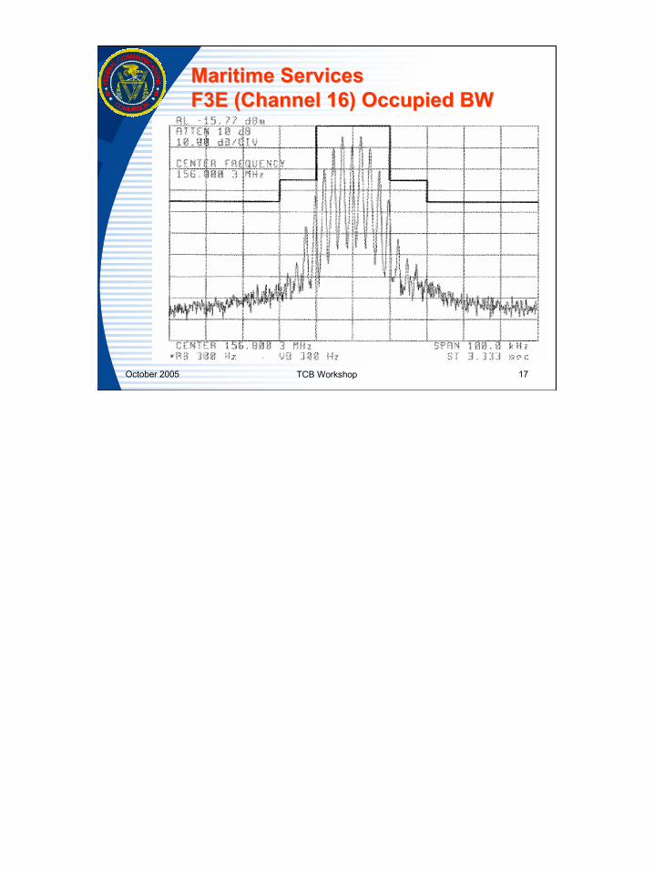
Maritime ServicesMaritime ServicesF3E (Channel 16) Occupied BWF3E (Channel 16) Occupied BW

18
October 2005 TCB Workshop 18
Maritime ServicesMaritime ServicesDSC (G2B Modulation, Channel 70) Occupied BWDSC (G2B Modulation, Channel 70) Occupied BW

19
October 2005 TCB Workshop 19
Maritime ServicesMaritime ServicesVHF Handheld PTT RF ExposureVHF Handheld PTT RF Exposure
Categorically excluded: Section 1.1307(b)(2)Option 1 (Portables): Occupational Limits– Submit Occupational training material– Special exemption from the July 02 Exclusion List– SAR Report is not required
Option 2 (Portables): General Population Limits– SAR Report required
If Portable power > 7 Watts contact the FCC before proceeding for both Occupational and General Population limits

20
October 2005 TCB Workshop 20
Maritime ServicesMaritime ServicesVHF Handheld PTT RF Exposure (Cont.)VHF Handheld PTT RF Exposure (Cont.)
If applicant chooses to submit SAR - TCBs cannot review the application– Submitted to the FCC– No standard SAR procedures for 150 MHz devices
RF exposure training instructions and labeling information is required for portables and mobiles– To determine mobile separation distance an MPE
exhibit is required if separation distance not equal to 20 cm

21
October 2005 TCB Workshop 21
Maritime ServicesMaritime ServicesVHF Base Station RF Exposure VHF Base Station RF Exposure
Categorically excluded: Section 1.1307(b)(2)RF exposure training instructions and labeling information is required since these are mobilesTo determine mobile separation distance an MPE exhibit is required

22
October 2005 TCB Workshop 22
Maritime ServicesMaritime ServicesVHF Example GrantVHF Example Grant

23
October 2005 TCB Workshop 23
Maritime ServicesMaritime ServicesEPIRB EPIRB –– 406 MHz Frequencies406 MHz Frequencies
406 to 406.1 MHz Band dedicated to Search and Rescue (SAR) - Earth to Space, Rules now allow equipment authorization anywhere within this band406 to 406.1 MHz is an FCC protected band (Reference FCC 04-75)http://hraunfoss.fcc.gov/edocs_public/attachmatch/FCC-04-75A1.pdf
International Digital Emergency and Distress FrequenciesAs noted by RTCM and SARSAT, 406.025 MHz is no longer the sole international
digital distress frequency. According to the COSPAS-SARSAT 406 MHz Frequency Management Plan the International Telecommunication Union (ITU) has allocated the frequency band 406.0 – 406.1 MHz for the use of low power satellite position-indicating radio beacons.[1] COSPAS-SARSAT has divided this frequency band into channels to ensure that the distress beacon traffic does not exceed the system’s capacity.[2] Channels are opened as beacon production demands increase and the beacon population grows. According to the 406 MHz channel assignment table, the window for type approval of new beacon models at 406.025 MHz (channel B) closed on January 1, 2002. The next frequency, 406.028 MHz or channel C, opened on January 1, 2000, and is scheduled to close on January 1, 2006. Opening dates for frequencies 406.037 MHz and 406.040 MHz have also already been assigned (January 1, 2004 and January 1, 2008 respectively). The frequencies on which it is possible for beacons to operate range from 406.025 MHz to 406.076 MHz.
[1] COSPAS-SARSAT 406 MHz Frequency Management Plan, C/S T.012, Issue 1 - October 2002 at H-2.
[2] Id. at 4-5.

24
October 2005 TCB Workshop 24
Maritime ServicesMaritime ServicesEPIRB TypesEPIRB Types
Class A - Section 80.1053– 121.5/243 MHZ. Float-free, automatically-activating, detectable by
aircraft and satellite. Coverage is limited. An alert from this device to a rescue coordination center may be delayed 4 - 6 or more hours. No longer recommended or Granted.
Class B – Section 80.1055– 121.5/243 MHZ. Manually activated version of Class A. No longer
recommended or Granted Class C – Section 80.1057– VHF ch15/16. Manually activated, operates on maritime channels
only. Not detectable by satellite. These devices have been phased out by the FCC and are no longer recognized. Grants can still be issued.
Class S – Section 80.1059– 121.5/243 MHZ. Similar to Class B, except it floats, or is an integral
part of a survival craft. No longer recommended or Granted Note: Subpart 2N - Test Procedure for Class A, B, and S EPIRBs is
obsolete since they no longer can be Granted
Inmarsat E-EPIRB (1.4 GHz) to discontinue operation after December 1, 2004After 8 years of service only 100 L-Band EPIRBSs fitted to GMDSS ships and less than 1300 L-Band EPIRBs fitted worldwideInmarsat L-Band maintenance contracts expireOther Inmarsat service not affected

25
October 2005 TCB Workshop 25
Maritime ServicesMaritime ServicesEPIRB CategoriesEPIRB Categories
Category II– 406/121.5 MHZ. Similar to Category I, except is
manually activated. Some models are also water activated.
Category I– 406/121.5 MHZ. Float-free, automatically activated
EPIRB. Detectable by satellite anywhere in the world. Recognized by GMDSS.
Include Bracket information for Category I/II in Grant condition

26
October 2005 TCB Workshop 26
Maritime ServicesMaritime ServicesEPIRBsEPIRBs –– CospasCospas--SarsatSarsat SatelliteSatellite
121.5 MHz – civilian use243 MHz – military use406-406.1MHz – vessel/aircraft info. and registration info. from databaseBeginning in 2009, only 406 MHz beacons will be detected by the Cospas-Sarsat satellite system. http://www.sarsat.noaa.gov/121phaseout.pdf
Phase out - This affects all maritime beacons (EPIRBs), all aviation beacons (ELTs) and all personal beacons (PLBs).
This decision has been made by the international organization that controls the satellites to reduce false alarms. About 97 per cent of all 121.5 MHz analogue beacon detections are false alarms and this is placing an unnecessary strain on the global search and rescue system. The change has been made to ensure that scarce search and rescue assets needed for a genuine emergency are not caught up chasing false alerts. False alarms from digital 406 MHz beacons can be resolved with a phone call as these devices transmit an identity code that can be cross-referenced with an ownership database.

27
October 2005 TCB Workshop 27
Maritime ServicesMaritime ServicesEPIRBsEPIRBs –– System ComparisonSystem Comparison
406 MHz Beacon 121.5 MHz Beacon Signal Digital: unique
identification, registration data provides information on the owner/vessel or aircraft
Analog: no data encoded, higher false alert rate
Signal Power 5 Watts pulse 0.1 Watts continuous Coverage Global Regional Position Accuracy Within 5 km (Doppler),
100m if GNSS (GPS) position is encoded in message
Within 20 km (Doppler only)
Alert Time GEO alert within 5 minutes Waiting time for LEO satellite pass 45 minutes average
Doppler Position Ambiguity
Resolved at first satellite pass
Two passes required to resolve position ambiguity
With a 121.5 MHz beacon, only one alert out of every 50 alerts is a genuine distress situation. This has a significant effect on the resources of search and rescue (SAR) services. With 406 MHz beacons, false alerts have been considerably reduced (about one alert in 17 is genuine) and when properly registered can normally be resolved with a telephone call to the beacon owner using the encoded beacon identification. Consequently, real alerts can receive the attention they deserve. When a 406 MHz beacon signal is received, SAR authorities can retrieve information from a registration database. This includes beacon owner contact information, emergency contact information, and vessel/aircraft identifying characteristics. Having this information allows SAR services to respond appropriately. Make sure your 406 MHz beacon is properly and accurately registered!

28
October 2005 TCB Workshop 28
Maritime ServicesMaritime ServicesEPIRBsEPIRBs –– International StandardsInternational Standards
SPECIFICATION FOR COSPAS-SARSAT 406 MHz DISTRESS BEACONS C/S T.001 Issue 3 - Revision 6 October 2004http://www.cospas-sarsat.org/DocumentsTSeries/T1Oct04.pdf
RTCM Recommended Standards for 406 MHz Satellite Emergency Position-Indicating Radiobeacons(EPIRBs), Version 2.1 - purchase paper copy (electronic version not available)https://ssl29.pair.com/dmarkle/puborder.php?show=7
Section 80.1061(a) - Notwithstanding the provisions in paragraph (b) of this section, 406.0–406.1 MHz EPIRBs must meet all the technical and performance standards contained in the Radio Technical Commission for Maritime Services document entitled RTCM Paper 77–02/SC110–STD, “RTCM Recommended Standards for 406 MHz Satellite Emergency Position-Indicating Radiobeacons (EPIRBs),” Version 2.1, dated June 20, 2002 (RTCM Recommended Standards).
IMO Resolution A.810(19), “Performance Standards for Float-free Satellite Emergency Position-indicating Radio Beacons (EPIRBs) Operating on 406 MHz,” with Annex, adopted 23 November 1995, and IMO Resolution A.812(19), “Performance Standards for Float-free Satellite Emergency Position-indicating Radio Beacons Operating Through the Geostationary INMARSAT Satellite System on 1.6 GHz,” with Annex, adopted 23 November 1995.
ITU-R Recommendation M.633–2, “Transmission Characteristics of a Satellite Emergency Position-indicating Radiobeacon (Satellite EPIRB) System Operating Through a Low Polar-orbiting Satellite System in the 406 MHz Band,” 2000.

29
October 2005 TCB Workshop 29
Maritime ServicesMaritime ServicesEPIRBsEPIRBs –– Equip. AuthorizationEquip. Authorization
All standards data required, even if not applicable for equipment authorization. Legal requirement.Approved Test Laboratories– Indoor tests – no TX to satellite– Outdoor tests – functional test w/ TX to satellite– Important to check application for approved test lab
for 406 MHz devices. List available:http://www.cospas-sarsat.org/Beacons/beaconTypeApprovalLabs.htm

30
October 2005 TCB Workshop 30
Maritime ServicesMaritime ServicesEPIRBsEPIRBs –– Equip. AuthorizationEquip. Authorization
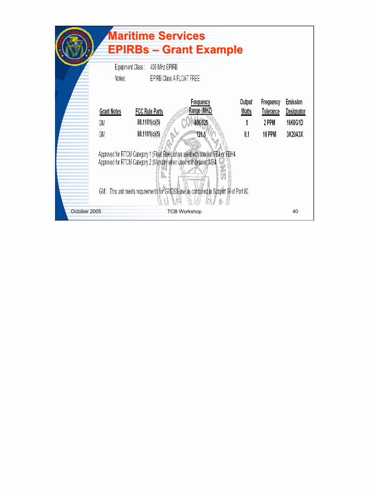
Equipment Class – GEP 406 MHz EPIRBNote Code – “GM” for GMDSS complianceUse 80.1101(c)(5) on 121.5 and 406 MHz line items Section 80.1101(c)(5) 406.0–406.1 MHz EPIRBs:– (i) IMO Resolution A.810(19), “Performance Standards for
Float-free Satellite Emergency Position-indicating Radio Beacons (EPIRBs) Operating on 406 MHz,” with Annex, adopted 23 November 1995, and IMO Resolution A.812(19), “Performance Standards for Float-free Satellite Emergency Position-indicating Radio Beacons Operating Through the Geostationary INMARSAT Satellite System on 1.6 GHz,” with Annex, adopted 23 November 1995.

31
October 2005 TCB Workshop 31
Maritime ServicesMaritime ServicesEPIRBsEPIRBs –– Equip. AuthorizationEquip. Authorization
– (iii) ITU-R Recommendation M.633-1, “Transmission Characteristics of a Satellite Emergency Position-indicating Radiobeacon(Satellite EPIRB) System Operating Through a Low Polar-orbiting Satellite System in the 406 MHz Band,” 1990.
– (iv) The 406.0-406.1 MHz EPIRBs must also comply with 80.1061.
No RF Exposure Exhibit required – low duty factor

32
October 2005 TCB Workshop 32
Maritime ServicesMaritime ServicesEPIRBsEPIRBs –– Approval Letter ExhibitsApproval Letter Exhibits
All EPIRBs require US Coast Guard approval letterCOSPAS – SARSAT Certificate

33
October 2005 TCB Workshop 33
Maritime ServicesMaritime ServicesEPIRBsEPIRBs –– Example certificateExample certificate

34
October 2005 TCB Workshop 34
Maritime ServicesMaritime ServicesEPIRB EPIRB –– 406 MHz Frequencies406 MHz Frequencies
The frequency change from 406.025 MHz to 406.028 MHz was allowed as an option of the manufacturer, but will be mandatory for new beacon models presented for certification and approved by COSPAS/SARSAT after January 1, 2002. New Grants must list the new frequency.406.028 MHz required to prevent saturation of satellites at the old frequency (406.025 MHz). Reference FCC 02-102.http://hraunfoss.fcc.gov/edocs_public/attachmatch/FCC-02-102A1.pdf

35
October 2005 TCB Workshop 35
Maritime ServicesMaritime ServicesEPIRBsEPIRBs –– 406 MHz Characteristics406 MHz Characteristics
Frequency Tolerance: short-term variations 2 ppm in 100 ms. Long-term variations +2 kHz /-5 kHz from 406.028 MHz in 5 years.Power Output: 5 W + 2 dB (35 to 39 dBm)Maximum Continuous Transmission: maximum of 45 secondsEmissions Designator – 16K0G1D

36
October 2005 TCB Workshop 36
Maritime ServicesMaritime ServicesEPIRBsEPIRBs –– 406 MHz Mask406 MHz Mask

37
October 2005 TCB Workshop 37
Maritime ServicesMaritime ServicesEPIRB EPIRB –– 121.5 MHz Characteristics121.5 MHz Characteristics
RF Signal Transmitted – power : 50 - 100 mW PERP* – Transmission life : 48 hours – Frequency : 121.5 MHz +/- 6 kHz – Polarization : Linear
Modulation– Sweep rate : 2 - 4 Hz – Range : 300-1600 Hz (swept at least 700 Hz) – Modulation type : AM – Modulation depth : > 85% – Duty Cycle : 40%
Emissions Designator – 3K20A3X* Peak Effective Radiated Power relative to a 1/4 wavelength
monopole mounted on a ground plane
It is estimated that there are almost 700,000 121.5 MHz beacons in use world-wide. The list below gives typical 121.5 MHz beacon signal characteristics. Most of these units are used aboard aircraft and are required to meet national specifications based on ICAO standards.Transmission characteristics of 121.5 MHz beacons are given in ITU Radio-Regulations Appendix 37-A, and included in ITU Recommendation ITU-R M.690-1.The initial ICAO standards were not established with the aim of satellite reception of 121.5 MHz signals. The 121.5 MHz Cospas-Sarsat system was designed to serve the existing type of beacons, even though system performance is constrained by their characteristics. Parameters such as system capacity (number of simultaneous transmissions in the field of view of the satellite which can be processed by LEOLUTs) and location accuracy are limited. No information is usually provided about the operator's identity, although a morse coding of the signal is included in some models; however, these data are not processed automatically by Cospas-Sarsat LEOLUTs. Despite the limitations described above, the efficiency of 121.5 MHz beacons has been greatly enhanced by the use of satellite detection and Doppler location techniques.121.5 MHz beacons carried aboard aircraft can usually be activated both manually and automatically by shock (using a crash sensor or G switch). This latter feature has led to numerous false alerts when a beacon is mounted in an aircraft with insufficient care or when an aircraft makes a "hard landing". By providing the location of transmitting beacons, Cospas Sarsat can be instrumental in the quick processing of false alerts.

38
October 2005 TCB Workshop 38
Maritime ServicesMaritime ServicesEPIRBsEPIRBs –– 121.5 MHz Mask121.5 MHz Mask

39
October 2005 TCB Workshop 39
Maritime ServicesMaritime ServicesEPIRBsEPIRBs –– Labeling RequirementsLabeling Requirements
FCC ID and Section 80.1103(e)– “The owner of this 406.0–406.1 MHz EPIRB must register the
NOAA identification code contained on this label with the National Oceanic and Atmospheric Administration (NOAA) whose address is: NOAA, NOAA/SARSAT Beacon Registration, E/SP3, Federal Building 4, Room 3320, 5200 Auth Road, Suitland, MD 20746–4304.” Vessel owners shall advise NOAA in writing upon change of vessel or EPIRB ownership, transfer of EPIRB to another vessel, or any other change in registration information. NOAA will provide registrants with proof of registration and change of registration postcards.”
RTCM Label– “USE ONLY DURING SITUATIONS OF GRAVE AND
IMINENT DANGER”
40
October 2005 TCB Workshop 40
Maritime ServicesMaritime ServicesEPIRBsEPIRBs –– Grant ExampleGrant Example

41
October 2005 TCB Workshop 41
Maritime ServicesMaritime ServicesUniversal Universal ShipborneShipborne Automatic Identification Automatic Identification System (AIS)System (AIS)
Equipment Class – Automatic Identification Systems (AIS)US Coast Guard AIS background material:http://www.navcen.uscg.gov/enav/ais/default.htm
DA 02-1363 AIS Frequency Usagehttp://hraunfoss.fcc.gov/edocs_public/attachmatch/DA-02-1362A1.pdfDA 02-1499 AIS Applicable International Standards (Footnote 2) – STANDARDS MUST BE PURCHASED to Certify AIS deviceshttp://hraunfoss.fcc.gov/edocs_public/attachmatch/DA-02-1499A1.pdf
Certification of AIS equipment in the United States In June 2002, the FCC released a Notice entitled "Applications For Equipment Authorization Of Universal ShipborneAutomatic Identification Systems To be Coordinated with U.S. Coast Guard To Ensure Homeland Security". Pending completion of FCC rulemaking, the FCC Laboratory will coordinate review of applications for certification of AIS equipment with the United States Coast Guard to ensure that the equipment meets all applicable international standards and requirements. Essentially, AIS manufacturers must meet the requirements of the FCC's regulations for equipment authorization, 47 CFR 2 Subpart J (beginning 2.901), and the Coast Guard's Navigational and Vessel Inspection Circular (NVIC) 8-01, Approval of Navigation Equipment for Ships. NVIC 8-01 describes the certification process for AIS and other navigation equipment described under the newly adopted SOLAS V. The Federal Communications Commission has requested comments on how its rules should be amended to accommodate AIS certification, in a further Notice of Proposed Rulemaking under Docket PR 92-257. Until these FCC rules are finally adopted, the procedures described in the FCC Notice and the NVIC should apply.

42
October 2005 TCB Workshop 42
Maritime ServicesMaritime ServicesAIS (AIS (Con’tCon’t))
DSC – Channel 70 14K2G2B (typical BW)AIS 1 – Channel 87 GXW w/ 12.5 and 25 kHz channel spacingAIS 2 – Channel 88B w/ 12.5 and 25 kHz channel spacingRemote Frequency Assignment by US Coast GuardTDMA (multiplexing)/Gaussian Minimum Shift Keying modulation (GMSK) – GXW
[2] The International standards and requirements identified are: IMO Resolutions A.694(17) and MSC.74(69), Annex 3; ITU-R 1371-1; IEC standards IEC 60945, IEC 61162 and IEC 61993-2.
OBW must be derived from the mask spectral plots (typically -26 dB BW) since this information is not typically provided by AIS applicants
Questions concerning AIS standards may be directed to Tim Maguire of the Wireless Telecommunications Bureau at [email protected] and concerning equipment authorization to Andrew Leimer at [email protected].

43
October 2005 TCB Workshop 43
Maritime ServicesMaritime ServicesAIS (AIS (Con’tCon’t))Radiated Emissions Limits – IEC 945

44
October 2005 TCB Workshop 44
Maritime ServicesMaritime ServicesAIS (AIS (Con’tCon’t))
TDMA Receiver Characteristics – IEC 61993-2
Problems with Receiver Standards – US Coast Guard can issue an approval letter for the following non-compliant standards with a rationale for recommending certification. Grant can be issued under there conditions.
15.3.4 - Co-channel rejection - 25 kHz operation15.3.5 - Co-channel rejection – 12.5 kHz operation15.3.6 - Adjacent channel selectivity - 25 kHz operation15.3.7 - Adjacent channel selectivity – 12.5 kHz operation15.3.9 - Intermodulation response rejection and blocking

45
October 2005 TCB Workshop 45
Maritime ServicesMaritime ServicesAIS (AIS (Con’tCon’t))
US Coast Guard Approval Letter RequiredApplicable FCC Rules– 80.209 Frequency Tolerance 10ppm– 80.211(f) Emissions Mask (category: other)
• Note that IEC mask is much tighter– 80.215(a)(1) Power 25 Watts for ship stations– 80.215(g)(3) Automatic 1 Watt power reduction
requirement for specific frequenciesApplication must contain data for ALL international standards
Note: application must include data for all international standards even though some of the standards are not applicable for FCC Certification and will not be reviewed. This is a legal requirement.

46
October 2005 TCB Workshop 46
Maritime ServicesMaritime ServicesAIS (AIS (Con’tCon’t))Standard AIS Grant Example
47
October 2005 TCB Workshop 47
Maritime ServicesMaritime ServicesAIS (AIS (Con’tCon’t))
Previously Automatic Identification Equipment (AIS) required a US Coast Guard approval letterU.S. / European Community Mutual Recognition Agreement on Marine Equipment - July 1st, 2004http://www.uscg.mil/hq/g-m/mse4/mra.htmAIS requires EC Accrediting Body Certificate –needs “Wheelmark” and a USCG Approval Number (Issued by EC Notification Body) on the Label Exhibits

48
October 2005 TCB Workshop 48
Maritime ServicesMaritime ServicesShip Security Alert Systems (SSAS)Ship Security Alert Systems (SSAS)
Homeland Security directive406 MHz SOSPAS-SARSAT system without 121.5 MHz homing beacon so messages are covert. Transmitter is essentially a modified 406 MHz EPIRB.http://www.cospas-sarsat.org/FirstPage/ssas.htm

49
October 2005 TCB Workshop 49
Maritime ServicesMaritime ServicesSSAS SSAS –– Equipment AuthorizationEquipment Authorization
Currently no applicable Rules so applications are processed under the requirements specified in DA 04-4052http://hraunfoss.fcc.gov/edocs_public/attachmatch/DA-04-4052A1.pdfEquipment Class – SSA (Ship Security Alert Systems)No RF Exposure required – low duty factorGrant condition – This device complies with the Ship Security Alert Systems (SSAS) provisions of DA 04-4052.Requires US Coast Guard Approval Letter
DA 04-4052Released: December 28, 2004Review of Applications for Equipment Authorization of Ship Security Alerting Systems (SSAS) Using the COSPAS/SARSAT Satellite SystemOn July 1, 2004, Chapter XI-2, Regulation 6, Revised Performance Standards for a Ship Security Alert System (SSAS), of the Safety of Life at Sea Convention, to which the United States is a signatory, went into effect. The SSAS provides a means for certain ships to transmit a covert security alert to shore to indicate that the security of the ship is under threat or has been compromised. The U.S. Coast Guard will assure that required vessels meet SSAS requirements during its inspection of vessels.The Commission’s Part 80 rules governing stations in the Maritime Service require certification for various radio transmitters used on board ships and by coast stations. The IMO Resolution recommended only functional requirements for the SSAS, not technical standards. Certain equipment meeting current Part 80 requirements may be utilized to meet SSAS requirements. In addition, there is equipment that meets the RTCM Recommended Standard for SSAS, but does not meet the current Part 80 requirements.[1] The Commission issued a Notice of Proposed Rule Making in PR Docket 00-48 that addresses the SSAS and seeks comment on certification requirements for the equipment.[2] During the pendency of the rulemaking proceeding, for SSAS equipment not meeting all current Part 80 requirements, the FCC Laboratory will review applications for certification under the RTCM recommended standard for SSAS equipment. Questions concerning SSAS standards may be directed to Jim Shaffer of the Wireless Telecommunications Bureau at [email protected], and questions concerning equipment authorization may be directed to Andrew Leimer of the Office of Engineering and Technology at [email protected].
[1] See RTCM Recommended Standards for Ship Security Alerting Systems (SSAS) Using the COSPAS/SARSAT Satellite System, Version 1.0, June 4, 2004.[2] See Amendment of Parts 13 and 80 of the Commission’s Rules Concerning Maritime Communications, Second Report and Order, Sixth Report and Order, and Second Further Notice of Proposed Rule Making, PR Docket 00-48, 19 FCC Rcd 3120, 3163-64 ¶ 85 (2004).

50
October 2005 TCB Workshop 50
Maritime ServicesMaritime ServicesSSAS SSAS –– International StandardsInternational Standards
Interim COSPAS-SARSAT Type Acceptance Procedures for SSAShttp://www.cospas-sarsat.org/DocumentsTSeries/095-enclosure.pdfFinal COSPAS-SARSAT Standards approved June 4, 2004– RTCM Paper 110-2004/SC110-STD– Currently not available on the Internet –
contact COSPAS-SARSAT for a copy

51
October 2005 TCB Workshop 51
Maritime ServicesMaritime ServicesRadars Radars –– Frequency BandsFrequency Bands
Frequency Bands– 2450–2500 MHz– 2900–3100 MHz– 5460–5650 MHz– 9300–9500 MHz– 14.00–14.05 GHz
This presentation focuses on the 9300-9500 MHz band since the majority of new devices only use this band

52
October 2005 TCB Workshop 52
Maritime ServicesMaritime ServicesRadars Radars –– Applicable RulesApplicable Rules
R.F. Power Output– Sections 2.1046(a), 80.215 – “mean power”– Duty Cycle = P.R.F. x Pulse Width– Peak Power = Average Power/Duty Cycle– Note: high peak power & low average power
Modulation Characteristics– Section 2.1047– P0N (Pulsed CW Radars)– Pulse widths (typically selectable for range)– PRF
Occupied Bandwidth– Sections 2.1049(c)(1), 80.209(b), 80.211(f)
80.213(g) Radar stations operating in the bands above 2.4 GHz may use any type of modulation consistent with the bandwidth requirements in §80.209(b).80.213(h) Radar transponder coast stations using the 2900–3100 MHz or 9300–9500 MHz band must operate in a variable frequency mode and respond on their operating frequencies with a maximum error equivalent to 100 meters. Additionally, their response must be encoded with a Morse character starting with a dash. The duration of a Morse dot is defined as equal to the width of a space and 1/3 of the width of a Morse dash. The duration of the response code must not exceed 50 microseconds. The sensitivity of the stations must be adjustable so that received signals below −10 dBm at the antenna will not activate the transponder. Antenna polarization must be horizontal when operating in the 9300–9500 MHz band and either horizontal or both horizontal and vertical when operating in the 2900–3100 MHz band. Racons using frequency agile transmitting techniques must include circuitry designed to reduce interference caused by triggering from radar antenna sidelobes.

53
October 2005 TCB Workshop 53
Maritime ServicesMaritime ServicesRadars Radars –– Applicable Rules (Cont.)Applicable Rules (Cont.)
Spurious Emissions at Antenna Port– Sections 2.1051, 80.211(f)
Radiated Spurious Emissions – Sections 2.1053, 80.211(f)
Frequency Stability – temperature & voltage variation– Sections 2.1055, 80.209(b)– 1.5/T where T=Pulse Duration (microseconds)– Example for 9300-9500 MHz Band – frequency
must be within• Upper Limit = 9500 – 1.5/T• Lower Limit = 9300 + 1.5/T
80.211(f) The mean power when using emissions other than those in paragraphs (a), (b), (c) and (d) of this section:(1) On any frequency removed from the assigned frequency by more than 50 percent up to and including 100 percent of the authorized bandwidth: At least 25 dB;(2) On any frequency removed from the assigned frequency by more than 100 percent up to and including 250 percent of the authorized bandwidth: At least 35 dB; and(3) On any frequency removed from the assigned frequency by more than 250 percent of the authorized bandwidth: At least 43 plus 10log10 (mean power in watts) dB.
80.209(b) When pulse modulation is used in land and ship radar stations operating in the bands above 2.4 GHz the frequency at which maximum emission occurs must be within the authorized bandwidth and must not be closer than 1.5/T MHz to the upper and lower limits of the authorized bandwidth where “T” is the pulse duration in microseconds. In the band 14.00–14.05 GHz the center frequency must not vary more than 10 MHz from 14.025 GHz.

54
October 2005 TCB Workshop 54
Maritime ServicesMaritime ServicesRadars Radars –– International standardsInternational standards
Section 80.273 Technical requirements for radar equipment – list of applicable standardsRTCM Paper 133–87–SC 103–33– RTCM Recommended Performance Specification for a
General Purpose Navigational Radar Set for Oceangoing Ships of 500 Gross Tons and Upwards for New Radar Installations
RTCM Special Committee No. 65 Final Report– Performance Specification for a General Purpose Navigational
Radar Set for Oceangoing Ships of 1,600 Tons Gross Tonnage and Upwards for New Radar Installations
International Standards are under review
80.273(a)(1) Radar installed on or after July 1, 1988, on ships of 500 gross tons and upwards that were constructed on or after September 1, 1984, must comply with the provisions of RTCM Paper 133–87–SC 103–33 including Appendix A. Title: “RTCM Recommended Performance Specification for a General Purpose Navigational Radar Set for Oceangoing Ships of 500 Gross Tons and Upwards for New Radar Installations.” Title of Appendix A: “General Purpose Shipborne Navigational Radar Set for Oceangoing Ships Design and Testing Specifications.” Document originally approved by RTCM August 15, 1985 and revised May 15, 1987. 80.273(a)(2) Radar installed on ships of 1,600 gross tons and upwards on or before April 27, 1981, must comply with the provisions of Volume II of RTCM Special Committee No. 65 Final Report; Part II. Title: “Performance Specification for a General Purpose Navigational Radar Set for Oceangoing Ships of 1,600 Tons Gross Tonnage and Upwards for Ships Already Fitted.” Document approved by RTCM July 18, 1978; effective as FCC requirement on April 27, 1981. 80.273(a)(3) Radar installed on ships of 1,600 gross tons and upwards after April 27, 1981 and before July 1, 1988, must comply with the provisions of Volume II of RTCM Special Committee No. 65 Final Report with Change 1 entered; Part I including Appendix A. Title: “Performance Specification for a General Purpose Navigational Radar Set for Oceangoing Ships of 1,600 Tons Gross Tonnage and Upwards for New Radar Installations.” Title of Appendix A: “General Purpose ShipborneNavigational Radar Set for Oceangoing Ships Design and Testing Specifications.” Document approved by RTCM July 18, 1978; effective as FCC requirement on April 27, 1981. 80.273(a)(4) Ships between 500 and 1,600 gross tons constructed on or after September 1, 1984, with radar installed before July 1, 1988, must comply with Regulation 12, Chapter V of the Safety Convention and with the provisions of Inter-Governmental Maritime Consultative Organization (IMCO) [now International Maritime Organization] Resolution A.477 (XII). Title: “Performance Standards for Radar Equipment,” with Annex. Adopted by IMCO November 19, 1981.

55
October 2005 TCB Workshop 55
Maritime ServicesMaritime ServicesRadars Radars –– Typical Measurement ProcedureTypical Measurement Procedure
The average power, pulse widths, pulse rise and decay times, and the interval between successive output pulses are measured (1/2 Voltage PW)The pulse repetition frequency (PRF) is then calculated from the reciprocal of the intervalThe duty cycle is calculated from the product of the P.F.R. and the pulse widthThe average power is corrected for attenuationThe peak power is calculated by dividing the average power by the duty cycleThe spurious and harmonic radiation characteristics, the occupied bandwidth and the receiver radiation are measured

56
October 2005 TCB Workshop 56
Maritime ServicesMaritime ServicesRadars Radars –– Equipment AuthorizationEquipment Authorization
Equipment Class – MRD (Marine Radar)Can list entire band on Grant but must have operational frequencies and frequencies parameters (Hopping, etc.) in the Operational DescriptionModulation P0N (Not PON)Necessary BW is typically several MHzMeasure all PW and OBW – preferable to include plots in the Test ReportConducted spurious radiationCase radiated measurements– Antenna terminated
No RF Exposure requirements

57
October 2005 TCB Workshop 57
Maritime ServicesMaritime ServicesRadars Radars –– Measured PWMeasured PW

58
October 2005 TCB Workshop 58
Maritime ServicesMaritime ServicesRadars Radars –– OBW RW #1OBW RW #1

59
October 2005 TCB Workshop 59
Maritime ServicesMaritime ServicesRadars Radars –– OBW PW#2OBW PW#2

60
October 2005 TCB Workshop 60
Maritime ServicesMaritime ServicesRadars Radars –– Grant ExampleGrant Example
Equipment Class – MRDList entire 9300-9500 MHz bandOutput Power – manufacturers rated peak powerFrequency Tolerance – leave blank (must comply)No RF Exposure Conditional Requirements Necessary

61
October 2005 TCB Workshop 61
Aviation ServicesAviation ServicesVHF RulesVHF Rules
118-137 MHz (Equipment Class – TNB)R&O and FNPRM - FCC 03-238 (Docket 01-289) –in effect as of 9/13/04http://hraunfoss.fcc.gov/edocs_public/attachmatch/FCC-03-238A1.pdfRequires FAA Coordination Prior to FCC FilingRemoves waiver requirement for equipment with 8.33 KHz channel spacingAllows for dual spacing transceivers (i.e 25/8.33 KHz)– 8.33 KHz operation not allowed in US

62
October 2005 TCB Workshop 62
Aviation ServicesAviation ServicesRadarsRadars
Similar to Marine (Part 80) RadarsEquipment Class – SRT9300-9500 MHzVery Few GrantsFAA Approval – Not Required

63
October 2005 TCB Workshop 63
Aviation ServicesAviation ServicesEmergency Location Transmitter (Emergency Location Transmitter (ELTsELTs))
121.5/406 MHz beacons carried aboard aircraft can usually be activated both manually and automatically by shock (using a crash sensor or G switch). False alerts w/G switch.Section 87.197 – ELT Test ProceduresSection 87.199 – Special RequirementsCOSPAS/SARSAT approved test facility required

64
October 2005 TCB Workshop 64
Aviation ServicesAviation ServicesELTsELTs -- StandardsStandards
FAA Standard TSO – C91A http://www.airweb.faa.gov/Regulatory_and_Guidance_Library/rgTSO.nsf/0/e2b1e589c98200f886256dc900695b8c/$FILE/C91a.pdfRadio Technical Commission for Aeronautics document titled “Minimum Operational Performance Standards 406 MHz Emergency Locator Transmitters (ELT)” Document No. RTCA/DO–204 dated September 29, 1989.

65
October 2005 TCB Workshop 65
Aviation ServicesAviation ServicesELTsELTs –– Approval Letter ExhibitsApproval Letter Exhibits
FAA Approval– Section 87.149(d)(2) for 121.5 MHz– Section 87.149(e) for 406 MHz
COSPAS – SARSAT Certificate

66
October 2005 TCB Workshop 66
Aviation ServicesAviation ServicesELTsELTs
Equipment Class – “GET” 406 MHz ELTMust have 121.5 MHz capabilitySection 87.139 – Emissions Mask for all bandsNo RF Exposure Exhibit Required
87.139(h): For ELTs operating on 121.500 MHz, 243.000 MHz and 406.0–406.1 MHz the mean power of any emission must be attenuated below the mean power of the transmitter (pY) as follows:(1) When the frequency is moved from the assigned frequency by more than 50 percent up to and including 100 percent of the authorized bandwidth the attenuation must be at least 25 dB; (2) When the frequency is removed from the assigned frequency by more than 100 percent of the authorized bandwidth the attenuation must be at least 30 dB.

67
October 2005 TCB Workshop 67
Thanks!Thanks!Thanks!