Embed Size (px)
Citation preview

PDF generated on 07 Aug 2017DISCLAIMER : UNCONTROLLED WHEN PRINTED – PLEASE CHECK THE STATUS OF THE DOCUMENT IN IDM
Technical Specifications (In-Cash Procurement)
Call for Nomination: Summary of the Technical Specification for ITER IVC Joints Develpment and
manufacturingThis document gives a general overview of the ITER In-Vessel coils system and will serve as a main document for the Call for Nomination for the ITER IVC joints design and manufacturing.It is related to the production of the stainless steel mineral insulated conductor (SSMIC) for the vertical stabilization (VS) and Edge Localized Mode (ELM) coils which are part of the ITER in-vessel coil (IVC) system.
IDM UID
V5MEWYVERSION CREATED ON / VERSION / STATUS
21 Jul 2017 / 1.1 / Approved
EXTERNAL REFERENCE / VERSION

Page 1 of 8
Call for Nomination
Summary of Technical Specification for the ITER IVC Joints Development and Manufacturing
Contents1. PURPOSE .........................................................................................................................................22. SCOPE OF THE SUPPLY .................................................................................................................23. PROCUREMENT STRATEGY .........................................................................................................24. DEFINITIONS ..................................................................................................................................35. DESCRIPTION OF ITER IN-VESSEL COILS SYSTEM ..................................................................36. INTRODUCTION OF IN-VESSEL COIL JOINTS............................................................................57. TOOLS..............................................................................................................................................68. IVC JOINTS DESIGN AND MANUFACTURING ............................................................................69. TESTS ...............................................................................................................................................710. STORAGE.........................................................................................................................................811. TRANSPORTATION ........................................................................................................................812. SCHEDULE ......................................................................................................................................813. EXPERIENCE REQUIREMENTS ....................................................................................................914. CANDIDATURE ...............................................................................................................................9

Page 2 of 8
1. PurposeThis document gives a general overview of the ITER In-Vessel coils system and will serve as a main document for the Call for Nomination for the ITER IVC joints development and manufacturing.The joints will be used in various places inside the Vacuum Vessel (VV) to connect feedthroughs, feeders and coils. ITER in-vessel coil (IVC) system consists of Vertical Stabilization (VS) and Edge Localized Mode (ELM) coils.The in-vessel environment is severe, characterized by large transient electromagnetic fields, high radiation flux, and high temperature. To withstand these conditions and provide the required functionality the IVCs are made of stainless steel mineral insulated conductor (SSMIC).
2. Scope of the supplyThe Contractor shall develop and manufacture at least three 1 m long Cu weld prototypes, welding head prototype, and three complete joint prototypes (at least 1 m long) for Phase I, 3 complete sets of joints manufacturing equipment/tooling and 2 presentative joints for Phase II. Detailed information will be given in the Call for Tender documentations.
3. Procurement Strategy IO will be fully responsible for this procurement. It is intended to split the procurement of the IVC joint development and manufacturing into two main phases. Splitting the scope in this way should allow any potential advantages offered by different need dates to be fully exploited. The two Phases will cover the following items: Phase I - Joint design and manufacturing procedures development :
- Cu tube and SS jacket WPS (Welding Procedure Specification) and WPQR (Welding Procedure Qualification Report)
- Cu welding equipment prototype- Three (0º, 45º and 90º) Cu weld prototypes - Three complete joint prototypes (0º, 45º and 90º)
Phase II - Joint design and manufacturing procedure verification and equipment manufacturing:- 6 representative type IVC joints in-situ manufacturing procedure and qualification
report- 3 complete joint prototypes manufactured under in-situ condition- 3 complete sets of joints manufacturing equipment and tooling- 2 representative type IVC joints manufactured in TTTF
Note: TTTF (Trial, Test and Training Facility) is a mock-up being built on ITER site and used for qualification and testing dedicated tools for components assembly in the ITER VV.Moreover, the contract for Phase II include some special qualification tests, i.e. fatigue S-N tests for Cu and SS jacket welds, mechanical vibration tests for complete joints. This Call for Nomination refers only to the joints development and manufacturing. Multiple suppliers can be selected for phase I (process qualification and production of prototypes) in order to maintain competition and keep the cost within acceptable limits. One supplier will be

Page 3 of 8
selected for Phase II (the qualification procedure), with one back-up supplier if costs are comparable, to mitigate schedule risks.
4. DefinitionsFor a complete list of ITER abbreviations see: ITER_D_2MU6W5 - ITER Abbreviations
ELM coils Edge localized mode coilsVS coils Vertical stabilisation coilsIVC In-Vessel coilsVV Vacuum VesselIO ITER OrganizationRO Responsible OfficerSS Stainless SteelTBD To be definedTTTF Trial, Test and Training FacilityPBS Plant Breakdown Structure
5. Description of ITER In-Vessel coils systemITER is project now underway in France to construct a device that will demonstrate nuclear fusion power at a power plant relevant scale. ITER relies on magnetic confinement of a deuterium – tritium plasma to achieve thermonuclear conditions. The main components of the magnetic field are supplied by superconducting coils located outside the ITER vacuum vessel.However, a set of in-vessel coils (IVCs) is required to make local adjustments to the field on a fast time scale.ITER is incorporating two types of In-Vessel Coils (IVCs): ELM Coils to mitigate Edge Localized Modes and VS Coils to provide Vertical Stabilization of the plasma. Strong coupling with the plasma is required so that the ELM and VS Coils can meet their performance requirements. Accordingly, the IVCs are in close proximity to the plasma, mounted just behind the Blanket Shield Modules (BSM). This location results in a radiation and temperature environment that is severe necessitating new solutions for material selection as well as challenging analysis and design solutions. Fitting the coil systems in between the blanket shield modules and the vacuum vessel leads to difficult integration with diagnostics and cooling water manifolds.

Page 4 of 8
ELM Coils(3 per
sector)
Upper VS Coil
ELM Feeders(27 sets in
Upper Ports)
Lower VS Coil
The ELM coils consist of three (upper, midplane, and lower) 6-turn rectangular “picture frame coils”, for a total of 27 coils mounted to the vacuum vessel and positioned behind the BSM.The VS coils consist of one upper and one lower 4-turn solenoidal “ring” coil connected in an anti-series “saddle” arrangement. The coils are mounted to the vacuum vessel and positioned behind the blanket shield modules.To withstand the severe environment and provide the required functionality a “mineral insulated conductor” (MIC) technology has been selected for the IVC conductor. Figure 2 shows the MIC configuration, consisting of an axially water-cooled copper conductor surrounded by mineral insulation and a stainless steel jacket.
Figure 2: Mineral Insulated Conductor
Cross-section of the Mineral-Insulated Conductor for ITER ELM and VS in-vessel coils is as shown in Figure 3.
Figure 1: Layout of the IVCs inside the machine
Page 5 of 8
Figure 3. Cross-section of the Mineral-Insulated Conductor for ITER ELM and VS in-vessel coilsAll IVCs are supported via bolts to the rails which are welded to the VV wall.
6. Introduction of In-Vessel coil jointsThere are totally 176 IVC joints for joining the wound IVC coils, feeders and feeder through. Every individual VS turn includes 4 joints, thus totally 32 joints for the 2 VS coils and 144 joints for the 27 ELM coils. The quantity and orientations for the joints are summarized in table 1. All of the joints will be manufactured in the ITER vacuum vessel and made of SSMIC to withstand the severe environment as coils themselves. The minimum available space from copper to VV or PBS is limited in 60 mm. Free Copper for joints is about 160 mm, and the length between the two clamps distributed at the two ends of the joints is about 220 mm (as shown in Figure ). According to the characteristic and space reservation, the joints are classified into 6 types. Details see table 1.
Coil No. Position Quantity Orientation (to Z direction) Joint type
Feedthrough to Feeder 8 0º IUPR-VS
Feeder to coil 8 90º II
Feedthrough to Feeder 8 90º VILWR-VS
Feeder to coil 8 50º V
Feedthrough to Feeder 18 0º IUPR-ELM
Feeder to coil 18 45º III
Feedthrough to Feeder 18 0º I
Feeder to IV-Feeder 18 45º III
EQ-ELM
IV-feeder to coil 18 9 / 45º; 9 / 90º IV-1; IV-2
Feedthrough to Feeder 18 0º I
Feeder to IV-Feeder 18 45º III
LWR-ELM
IV-feeder to coil 18 8 / 50º ; 10 / 90º IV-1; IV-2

Page 6 of 8
Table 1. ITER In-vessel coils joints position and quantity
Upper VS
Upper ELM
Equatorial ELM
Lower ELM
Lower VS
~220mm
~160mm
0 º 90 º
45 º
50 º
Figure 4. Reference distribution and orientation for IVC joints
7. ToolsAll tools and equipment required for the production and testing either bespoke or standard are the responsibility of the contractor.
8. IVC joints design and manufacturingThe “mineral insulated conductor” (MIC) technology shall also be selected for the joints design and manufacturing, composed of welded Cu tubes, insulation and SS jackets, to withstand the environment and provide the required functionality as the conductor, see Figure 5.
Page 7 of 8
1) Removal of the temporary sealing
2) Insulation application
3) Jacket application
Jacket shells
Jacket sleeves
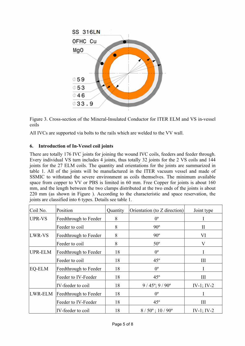
Figure 5. The schematic of joints manufacturingThe main processes of the joints manufacturing includes:
- Removal of the temporary sealing- Cu tube welding- Insulation and jacket application
It is required to perform full penetration welds by using orbital (machine) welding to enable full control and reproducibility for Cu tube welding. The designed of welding equipment and tooling shall be useful with the constraint environment in ITER vacuum vessel. Attention shall also be taken on the mechanical and electrical performance of the Cu welds. Equivalent mechanical and electrical performance as the Cu tube itself are required.Particular attention shall be given to the development of insulation and jacket application. The insulation performance shall be equivalent or better than the one of the conductor. Around the insulation steel jacket shells or sleeves with a minimum thickness of 3 mm shall be installed to provide mechanical support of the joint and a closed containment for the insulation. One of the most important requirements is that the whole procedure shall follow the requirements listed in ITER Vacuum Handbook, including requirements for the used materials and the cleanliness.
9. TestsAll testing operations to be carried out by the Supplier shall be described in the Call for Tender documentation. The Supplier shall prepare Test Procedures for all testing operations and submit them to the IO for acceptance. The Supplier shall perform the acceptance testing before shipping the required prototypes to the IO. For each milestone the Supplier shall provide support necessary to test the component/system to demonstrate that the required performance meet the criteria.

Page 8 of 8
In order to allow the IO to perform the on-site testing, the Supplier shall prepare sufficiently in advance and submit to the IO the information related to testing tasks (type, prerequisites, interfaces, etc...), including any kind of activities during site reception test, on-site component test, on-site system test and on-site system commissioning.
10. StorageThe prototype Cu welds, complete joints and the equipment and tooling should be packed and stored at the supplier premises for certain duration of time. Storage conditions will be described in details in the Call for Tender documentations.
11. TransportationThe Cu welds, complete joint prototypes and joint manufacturing equipment and tooling, as described in section 2, should be delivered to ITER premises.All required test equipment and tooling should also be delivered to ITER premises before joints manufacturing processes verification in TTTF.
12. Schedule
Call for Nomination August- September 2017Pre-Qualification October 2017Call for Tender November 2017Tender Submission January 2018Award of Contract March-April 2018Delivery of Cu welds, joints and welding head prototypes To IO premises
16 months from Contract signature
Delivery of representative complete joint prototypes and 3 sets of equiment and toolingTo IO premises
3 years from Contract signature
Table 2. Schedule for Call for Tender activities
13. Experience requirementsThe ITER Organization is looking for suppliers which experience and knowledge is based on the following main criteria:
Understanding of the design and manufacturing requirements; Experience in compaction process; Experience with an appropriate procurement for material and associated
inspection/testing; Knowledge/experience in welding, especially welding in limited space; Knowledge/experience in handling of mineral insulation materials i.e. MgO; Knowledge/experience in performing the mechanical, electrical and non-
destructive tests; Relevant QA/QC; Presence of required machining equipment;
Page 9 of 8
Sufficient equipment and facilities to meet the requirements as related to the scope of work;
Sufficient storage space;
During the selection phase, ITER Organization reserves the right to contact some or all of each nominated company’s references to ask if: (1) the nominated company delivered a quality product which was compliant with the customer’s requirements; (2) the company’s performance conformed with the terms and conditions of its contract, including the delivery schedule; and (3) the company was reasonable and cooperative during performance and committed to customer satisfaction. ITER Organization may choose to visit customer references and may also use other sources of information.
14. CandidatureCandidature is open to all companies participating either individually or in a grouping (consortium) which is established in an ITER Member State. A consortium may be a permanent, legally-established grouping or a grouping, which has been constituted informally for a specific tender procedure. All members of a consortium (i.e. the leader and all other members) are jointly and severally liable to the ITER Organization.The consortium groupings shall be presented at the tender submission stage. The consortium cannot be modified later without the approval of the ITER Organization.


![Technical Specifications (In-Cash Procurement) VALVES ...fusionforenergy.europa.eu/downloads/procurements/itercalls/572/... · [2.18] ASME B1.1-2003, “Unified Inch Screw Threads,](https://img.dokumen.tips/doc/110x75/5b5034b27f8b9a206e8e0910/technical-specifications-in-cash-procurement-valves-218-asme-b11-2003.jpg)