Embed Size (px)
Citation preview

7/23/2019 Manual Stat X.PDF
http://slidepdf.com/reader/full/manual-stat-xpdf 1/13
Fireaway Inc. 5852 Baker Road • Minnetonka, MN 55345
Version 1.2.3November 2011
P/N 19001
F$*# S))*#++$(' S.+,#&+
Electric Generator Owner’s Manual

7/23/2019 Manual Stat X.PDF
http://slidepdf.com/reader/full/manual-stat-xpdf 2/13
INTRODUCTIONThank you for your purchase of a Stat-X® aerosol firesuppression system. This manual is designed to provide
you with a general understanding of the product, as wellas, general information on installation, operational, andmaintenance parameters. It is not a detailed design,installation, operation, and maintenance manual. A detailedmanual may be obtained by contacting the manufacturer:
Fireaway Inc.5852 Baker Road
Minnetonka, MN 55345U.S.A.
Stat-X systems are to be installed and periodicallyinspected by trained personnel. No modifications are to bemade to the installed system without consulting a qualifiedsystem designer. The system is made up of units testedwithin limitations contained in the detailed design,installation, operation, and maintenance manual. Thesystem designer must be consulted whenever changes areplanned for the system or the protected area. An authorizedinstaller or system designer must be consulted after thesystem has discharged.
SSTEM DESCRIPTIONGeneral
Stat-X systems combine an environmentally safe firesuppression agent, specially developed components, andhighly effective detection devices for rapid agentapplication. The resulting timely suppression of fire reducesproperty damage and products of combustion to the lowestpossible levels. These systems are electrically activated,are extremely compact, and totally eliminate the expensivepressure vessels, nozzles, and distribution piping
associated with other fire suppression systems. Stat-Xaerosol agent is extremely effective when compared to
alternative agents and generators are strategically placedthroughout the hazard area offering significant weight andspace savings over conventional systems. Stat-X systemsare designed for total flooding applications in accordancewith established design criteria. All installations must meetthe requirements of the local authority having jurisdiction.
Stat-X systems are used to suppress fires in specifichazards or equipment located in enclosed areas andconfined spaces where an electrically non-conductive
agent is required and where low weight/space toextinguishing capacity is a factor.
The fire-extinguishing agent is an ultra-fine aerosol, whichhangs in suspension for extended periods of time (up toone hour) providing excellent protection against re-flash,as well as, minimizing clean up. Stat-X systems aresuitable for use in unoccupied and normallyunoccupied areas. In areas where personnel may be
present the system must employ a pre-dischargealarm, 30-second time delay, and provision for systemisolation and manual only activation wheneverpersonnel are in the protected area. They are intended toprotect the following typical applications:
• Telecommunications Facilities• Flammable Liquid Storage Areas• Process Control Rooms
• Storage Vaults• Marine Engine Rooms*• Turbine Enclosures• High Value Mobile Equipment*• Power Plants• High Value Industrial Equipment Areas• Data Processing Facilities
*Not part of the UL Listing under UL Subject 2775 but are
covered under other applicable listings (American Bureau of Shipping, Marine and Coast Guard Agency, ECB, and others)
2

7/23/2019 Manual Stat X.PDF
http://slidepdf.com/reader/full/manual-stat-xpdf 3/13
Stat-X systems are not suitable for the following hazards;or, where the following materials may be present:
• Materials, which burn with deep-seated
characteristics (wood fiber, cotton, etc.)• Electrical equipment operating at over 40,000 V• Metal hydrides, pyrophoric substances, and
chemical substances that smolder and burnwithout air
• Metal powders (magnesium, titanium, etc.)• Environments rated hazardous (explosive
atmospheres).
Extinguishing AgentThe aerosol produced upon activation of a Stat-X systemsuppresses fire by a combination of chemical and physicalmechanisms similar to the Halons without any negativeeffect on the environment. Because of the aerosol’s ultra-fine particle size (≤ 2 micron) there is a dramatic increasein the surface area interaction between the agent and thefire. Potassium based aerosol has been shown in numerous
tests and scientific studies to be an extremely effectivealternative when compared to other currently availableextinguishing agents.
Unlike gaseous agents the aerosol does not decompose inthe presence of fire nor does it extinguish by oxygendeprivation. The aerosol is considered non-toxic to humanswhen applied in normal design concentrations necessary toextinguish most fires; however, certain safety restrictions
should be observed when applying and handling thegenerators. Exposure to the aerosol should be limited andunnecessary exposure to the particulate should be avoided.Exposure to the aerosol is generally of less concern than isexposure to the decomposition products of a fire.
Toxicity: Tests conducted by the Institute of Biophysics(Department of Public Health and Medicine RussianFederation) as well as others have shown that the aerosoldoes not present a health hazard due to limited accidentalexposure at normal design concentrations. Exposures
under five minutes are normally considered safe. Gas by-products are several times less than that allowable forautomobile airbag systems.
While the components of the aerosol are not consideredtoxic at normal concentration levels, ingestion of the ultra-fine particulate may cause short-term discomfort andunnecessary exposure should be avoided. Tests haveshown no long-term negative effects from exposure to theaerosol. The aerosol has a high obscuration factor whendischarged.
Stat-X is approved by the US EPA for use in unoccupied
and normally unoccupied areas (areas where personnelmay be present from time to time).
STAT-X SYSTEMS SHALL ONLY BE APPLIED IN AREASWHERE PERSONNEL MAY BE PRESENT IN CONJUNCTIONWITH A 30-SECOND TIME DELAY AND SYSTEM ISOLATESWITCH TO INSURE EGRESS OF PERSONNEL PRIOR TOSYSTEM DISCHARGE.
Corrosivity: Extensive tests have shown that the aerosol isnon-corrosive and non-harmful to a wide variety ofmaterials including structural metals, plastics, electricalcomponents, sophisticated materials used in aviation, film,and magnetic tape. In all cases it has been shown thatStat-X has no deleterious effect on the operating capabilityof equipment. Aerosol may cause minor surfacediscoloration of some metal alloys if not cleaned promptly— but this is a non-progressive event with no effect onfunctionality.
Cleanliness: The ultra-fine aerosol discharge remains insuspension for an extended period of time and can beeasily vented by a fan or air handling system. Minoramounts of aerosol, which may have settled on the floor orother horizontal surfaces, can be easily vacuumed or wipedclean with a water alcohol solution. Settled particulate isminor and is much less than the particulate produced bythe decomposition products of the fire.
Owner’s Manual
3

7/23/2019 Manual Stat X.PDF
http://slidepdf.com/reader/full/manual-stat-xpdf 4/13
Other Safety Considerations: The aerosol dischargedinto the hazard area upon activation of the generator isrelatively “cool.” However, the aerosol stream as it leaves
the generator is above 100°C for a very short distancefrom the outlet of the generator. Maximum temperaturesare realized only in the last seconds of discharge. Eachmodel has a required installation clearance distancespecified as its “C-zone”. Steps must be taken to insuregenerator placement so that it complies with thisinstallation requirement. The generator housing isapproximately 90°C immediately after discharge and careshould be taken if handling the post-discharge generatorprior to its cooling to ambient temperature.
Generators must never be installed to dischargedirectly on walls or equipment being protected,as this will cause agglomeration
Storage: Each Stat-X aerosol generator is sealed witha non-permeable membrane and is unaffected byfluctuations in temperature and humidity. Accelerated
aging tests have shown the generator's charge maintainsits viability for more than ten (10) years under conditionsranging from –40°C to +54°C and cycled relative humiditylevels up to 95%.
INSTALLATION AND MAINTENANCEFacility Considerations
Significant Obstructions/Agent Distribution: In caseswhere there is a large ratio of fixed equipment to totalvolume, or where the protected equipment is located insuch a way as to present a barrier to the free flow anddistribution of aerosol throughout the hazard area, the useof a larger number of smaller aerosol generators ispreferred. This will allow for strategic placement of theaerosol generators and improved distributioncharacteristics throughout the area.
INSTALLATION IN AREAS WHERE PERSONNEL MAY
BE PRESENT:
NOTE: IN AREAS WHERE PERSONNEL MAY BE PRESENT,
A 30-SECOND TIME DELAY SHALL BE INSTALLED TOINSURE EGRESS TIME PRIOR TO SYSTEM DISCHARGE.A SYSTEM ISOLATE SWITCH SHALL BE INSTALLEDOUTSIDE THE HAZARD AREA TO INSURE THATACTIVATION OF THE SYSTEM IS “MANUAL ONLY” WHENPERSONNEL ARE PRESENT.
Mounting: Stat-X aerosol generators are listed for bothsidewall and center locations and may be mounted onwalls, beams, constructions, and columns as long as theunit is securely bolted to the support structure and ismounted in a position where its “C-zone” (clearance zonewhere momentary peak temperature of the discharge willnot exceed 75°C) will not impact on personnel andequipment located within the protected area. HousingClearance is required spacing of generator fromcombustibles and structural materials.
Aerosol Stream Characteristics
Model C-Zone Height Max. Housing Clearance
30E 0.31m 0.5 to 1.22 m 7mm
60E 0.35m 0.5 to 2.00 m 7mm
100E 0.46m 0.5 to 2.50 m 13mm
250E 0.95m 0.5 to 2.75 m 13mm500E 1.27m 0.5 to 3.50 m 13mm
1000E 2.30m 0.5 to 4.88 m 13mm
1500E 2.00m 0.5 to 4.88 m 30mm
2500E 2.70m 0.5 to 4.88 m 30mm
Mounting Height: In general, the aerosol generators
should be mounted at or near ceiling height and angledtoward the floor at an angle to insure three-dimensional
4

7/23/2019 Manual Stat X.PDF
http://slidepdf.com/reader/full/manual-stat-xpdf 5/13
distribution of aerosol and an unobstructed discharge path.(15° – 30° for sidewall mounting). In order to insuremaximum distribution of aerosol throughout the hazard
area, the maximum height of generator placement must belimited as indicated above. Underfloor applications shouldbe mounted horizontally.
Flow: Placement of the aerosol generators to insure properaerosol flow and distribution is extremely important. Aerosolgenerators must never be positioned to dischargedirectly at each other! This will cause agglomeration of theaerosol particulate, reducing the aerosol's extinguishing
effectiveness. For the same reason, aerosol generatorsmust be positioned to insure that the aerosol streamdoes not impinge directly on walls or the sides ofequipment being protected.
Typical Placement
*Spacing S should be even unless prevented by obstruction.
Operating/Temperature Range: Stat-X aerosol generatorsare listed to operate within a temperature range of –40 °Cto +54 °C. The generators are sealed with a non-permeable
membrane and are unaffected by fluctuations in humidityand temperature.
EQUIPMENT INSTALLATIONGeneral. All Stat-X equipment must be installed to facilitateproper operation, inspection, testing, and any othermaintenance as may be necessary. Equipment must not besubject to mechanical, chemical, or other damage, which
could render the equipment inoperative. Equipment mustbe installed in accordance with all applicable standardsand the contents of this section of the manual.
WARNINGAEROSOL GENERATORS CONTAIN A FLAMMABLESOLID AND MUST ONLY BE HANDLED, INSTALLED,AND SERVICED BY A TRAINED TECHNICIAN USING THEINSTRUCTIONS CONTAINED IN THIS SECTION. FAILURE
TO FOLLOW THESE INSTRUCTIONS COULD CAUSE APREMATURE DISCHARGE AND POTENTIAL INJURY.
Aerosol Generator Installation. The Stat-X aerosolgenerators should normally be located within the protectedhazard area. The following installation instructions must befollowed in the exact sequence outlined below to preventaccidental discharge, bodily injury, or property damage.
WARNINGTO PREVENT PERSONAL INJURY, DE-ENERGIZE ALLELECTRICAL CONNECTIONS PRIOR TO GENERATORINSTALLATION.
Single Generator System:
1. Position mounting bracket and securely fasten to wall,ceiling, or other supporting structure in a location andmanner, which insures the generator will not be subjectedto accidental damage or movement.
Owner’s Manual
5
Equipment
C Zone
S
*
E q u i p m e n t
E q u i p m e n t
AerosolGenerators
7/23/2019 Manual Stat X.PDF
http://slidepdf.com/reader/full/manual-stat-xpdf 6/13
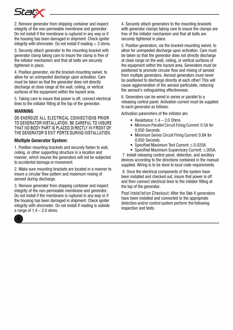
2. Remove generator from shipping container and inspectintegrity of the non-permeable membrane and generator.Do not install if the membrane is ruptured in any way or ifthe housing has been damaged in shipment. Check igniterintegrity with ohmmeter. Do not install if reading > 3 ohms.
3. Securely attach generator to the mounting bracket withgenerator clamp taking care to insure the clamp is free ofthe initiator mechanism and that all bolts are securelytightened in place.
4. Position generator, via the bracket-mounting swivel, toallow for an unimpeded discharge upon activation. Care
must be taken so that the generator does not directlydischarge at close range at the wall, ceiling, or verticalsurfaces of the equipment within the hazard area.
5. Taking care to insure that power is off, connect electricallines to the initiator fitting at the top of the generator.
WARNING
DE-ENERGIZE ALL ELECTRICAL CONNECTIONS PRIOR
TO GENERATOR INSTALLATION. BE CAREFUL TO INSURETHAT NO BODY PART IS PLACED DIRECTLY IN FRONT OFTHE GENERATOR’S EXIT PORTS DURING INSTALLATION.
Multiple Generator System:
1. Position mounting brackets and securely fasten to wall,ceiling, or other supporting structure in a location andmanner, which insures the generators will not be subjected
to accidental damage or movement.2. Make sure mounting brackets are located in a manner toinsure a circular flow pattern and maximum mixing ofaerosol during discharge.
3. Remove generator from shipping container and inspectintegrity of the non-permeable membrane and generator.Do not install if the membrane is ruptured in any way or ifthe housing has been damaged in shipment. Check igniter
integrity with ohmmeter. Do not install if reading is outsidea range of 1.4 – 2.0 ohms.
4. Securely attach generators to the mounting bracketswith generator clamps taking care to insure the clamps arefree of the initiator mechanism and that all bolts aresecurely tightened in place.
5. Position generators, via the bracket-mounting swivel, toallow for unimpeded discharge upon activation. Care mustbe taken so that the generator does not directly dischargeat close range on the wall, ceiling, or vertical surfaces ofthe equipment within the hazard area. Generators must bepositioned to promote circular flow and mixing of aerosolfrom multiple generators. Aerosol generators must never
be positioned to discharge directly at each other! This willcause agglomeration of the aerosol particulate, reducingthe aerosol's extinguishing effectiveness.
6. Generators can be wired in series or parallel to areleasing control panel. Activation current must be suppliedto each generator as follows:
Activation parameters of the initiator are:
• Resistance: 1.4 – 2.0 Ohms• Minimum Parallel Circuit Firing Current: 0.5A for
0.050 Seconds.• Minimum Series Circuit Firing Current: 0.8A for
0.050 Seconds.• Specified Maximum Test Current: ≤ 0.025A.• Specified Maximum Supervisory Current: ≤.005A.
7. Install releasing control panel, detection, and ancillarydevices according to the directions contained in the manual
supplied. Wiring is to be done to local code requirements.
8. Once the electrical components of the system havebeen installed and checked out, insure that power is offand then connect electrical lines to the initiator fitting atthe top of the generator.
Post Installation Checkout: After the Stat-X generatorshave been installed and connected to the appropriate
detection and/or control system perform the followinginspection and tests.
6

7/23/2019 Manual Stat X.PDF
http://slidepdf.com/reader/full/manual-stat-xpdf 7/13
1. Verify that generators of the correct size are installed perthe installation drawings.
2. Verify that generator mounting brackets and clamps are
properly installed and that all fittings are tight.3. Verify that all electrical connections have been made andtest for electrical continuity using an ohmmeter.
4. Verify that all generators are positioned properly. Check for obstructions in the path of the aerosol dischargestream. Generators must be installed such that they cannotcause personnel injury upon activation. The aerosoldischarge stream must not impinge at close range onwalls, ceiling, or vertical surfaces of equipment.
5. Manual/electrical pull stations must be properly installed,readily accessible, and clearly identified.
6. Verify time delay functionality and integrity.
7. All acceptance testing shall be in accordance with thismanual, any applicable standards, and the authority having jurisdiction.
OPERATIONGeneral. A solid charge of the aerosol composition iscontained within the sealed generator. Upon activation ofthe initiator, the charge begins a controlled burn producingan ultra-fine aerosol, which is ten times as effective as anyagent currently on the market. The aerosol passes throughan oxidation filter, where CO is converted to minor amountsof CO2, and then through a cooling bed where thetemperature of the aerosol is rapidly reduced before itescapes through the discharge ports of the generator atlow pressure. Generator placement within the hazard areaprovides proper flow and distribution of the highly effectiveaerosol within the protected area.
Operating Procedures
Electrical Automatic Operation: Electrical automaticoperation occurs upon activation of the detection circuit,
initiating a voltage source from the fire alarm panel to thegenerators. In areas where personnel may be present,a 30-second time delay shall be installed to insureegress time prior to system discharge. In occupiedand normally unoccupied areas, a system isolateswitch shall be installed outside the hazard area toinsure that activation of the system is “manual only”when personnel are present. Personnel must evacuatethe hazard area promptly upon hearing the pre-dischargealarm. Insure no one enters the hazard area after dischargeand call the fire department promptly.
Remote Electrical Manual Operation: Manual electricaloperation is performed by manual release from a releasingdevice located outside the protected enclosure. Operate asfollows:
1. Upon fire notification, leave the hazard area quickly
2. Proceed to the appropriate remote manual/electrical pullstation for the hazard.
3. Insure that all personnel have left the protected enclosure.
4. Operate manual pull station.
5. Allow no one to enter the hazard area. Call the firedepartment promptly.
System Isolate Switch: Unless prohibited by the localauthority having jurisdiction, the automatic operation of thesystem shall be prevented by means of a system isolateswitch (lockout/abort located outside the protected area)
when personnel are present in the hazard area. Theoperation of the system shall be manual only whenpersonnel are present. While the system isolate switch isactive the automatic activation of the system is inhibitedbut the fire detection and alarm system shall continue tofunction. The system shall return to full automatic controlwhen the switch is reactivated.
NOTETHE ABOVE INSTRUCTIONS MUST BE POSTED ONDISPLAY IN THE PROTECTED AREA.
Owner’s Manual
7
7/23/2019 Manual Stat X.PDF
http://slidepdf.com/reader/full/manual-stat-xpdf 8/13
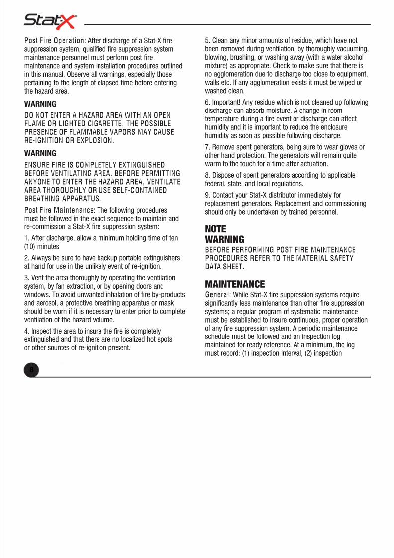
Post Fire Operation: After discharge of a Stat-X firesuppression system, qualified fire suppression systemmaintenance personnel must perform post firemaintenance and system installation procedures outlinedin this manual. Observe all warnings, especially thosepertaining to the length of elapsed time before enteringthe hazard area.
WARNING
DO NOT ENTER A HAZARD AREA WITH AN OPENFLAME OR LIGHTED CIGARETTE. THE POSSIBLEPRESENCE OF FLAMMABLE VAPORS MAY CAUSE
RE-IGNITION OR EXPLOSION.
WARNING
ENSURE FIRE IS COMPLETELY EXTINGUISHEDBEFORE VENTILATING AREA. BEFORE PERMITTINGANYONE TO ENTER THE HAZARD AREA, VENTILATEAREA THOROUGHLY OR USE SELF-CONTAINEDBREATHING APPARATUS.
Post Fire Maintenance: The following proceduresmust be followed in the exact sequence to maintain andre-commission a Stat-X fire suppression system:
1. After discharge, allow a minimum holding time of ten(10) minutes
2. Always be sure to have backup portable extinguishersat hand for use in the unlikely event of re-ignition.
3. Vent the area thoroughly by operating the ventilationsystem, by fan extraction, or by opening doors andwindows. To avoid unwanted inhalation of fire by-productsand aerosol, a protective breathing apparatus or mask should be worn if it is necessary to enter prior to completeventilation of the hazard volume.
4. Inspect the area to insure the fire is completelyextinguished and that there are no localized hot spots
or other sources of re-ignition present.
5. Clean any minor amounts of residue, which have notbeen removed during ventilation, by thoroughly vacuuming,blowing, brushing, or washing away (with a water alcoholmixture) as appropriate. Check to make sure that there isno agglomeration due to discharge too close to equipment,walls etc. If any agglomeration exists it must be wiped orwashed clean.
6. Important! Any residue which is not cleaned up followingdischarge can absorb moisture. A change in roomtemperature during a fire event or discharge can affecthumidity and it is important to reduce the enclosure
humidity as soon as possible following discharge.7. Remove spent generators, being sure to wear gloves orother hand protection. The generators will remain quitewarm to the touch for a time after actuation.
8. Dispose of spent generators according to applicablefederal, state, and local regulations.
9. Contact your Stat-X distributor immediately forreplacement generators. Replacement and commissioningshould only be undertaken by trained personnel.
NOTEWARNINGBEFORE PERFORMING POST FIRE MAINTENANCEPROCEDURES REFER TO THE MATERIAL SAFETYDATA SHEET.
MAINTENANCEGeneral: While Stat-X fire suppression systems requiresignificantly less maintenance than other fire suppressionsystems; a regular program of systematic maintenancemust be established to insure continuous, proper operationof any fire suppression system. A periodic maintenanceschedule must be followed and an inspection log
maintained for ready reference. At a minimum, the logmust record: (1) inspection interval, (2) inspection
8

7/23/2019 Manual Stat X.PDF
http://slidepdf.com/reader/full/manual-stat-xpdf 9/13
procedure performed, (3) maintenance performed, if any, asa result of inspection, and (4) the name of the responsibleperson performing the operation.
Preventive Maintenance. Perform preventive maintenanceper the following schedule at a minimum:
Schedule Requirement
Weekly Check all Electrical Connections
Visual inspection of Components
Six Month Inspect/Test all system components
Test electrical continuity
Inspect bracketing and positionof generators
Every 10 years Replace per date code on label
Inspection Procedures
Weekly
1. Check all electrical connections to insure operation ofthe Stat-X fire suppression system in the event of a fire.
2. Make a general visual inspection of all aerosolgenerators for damaged or missing parts.
Every Six Months
1. Make a general visual inspection of all aerosol
generators for damaged or missing parts.2. Ensure access to hazard areas, lines of egress, andmanual pull stations are unobstructed and that there are noobstacles inhibiting the proper operation of the aerosolgenerators or distribution of the aerosol in the event of a fire.
3. Inspect Stat-X aerosol generators for physical damage,such as cracks, dents, distortion, or corrosion. If damageis found, replace generator as instructed in Section 6 of
this manual.
4. Inspect mounting brackets, straps, and associatedhardware for loose, damaged, or broken parts. Replacedamaged parts and tighten all loose hardware.
5. Inspect all manual pull stations for cracks, broken orcracked glass plate, dirt or distortion. Inspect station forsigns of physical damage, replacing if necessary.
6. Inspect all electrical connections and run electricalcontinuity tests using an ohmmeter. Repair and replaceas necessary.
7. Replacement from service. The aerosol generators havean installed service life of ten (10) years. They are to bereplaced ten (10) years from the date code in the lowerright corner of the product label. The date code appears asfollows, where the alphabetic character represents the yearand the numeric the month of shipment from the factory:
A B C D 1 2 3 4 5 6 7 8 9 10 11 12
A = 2001, B = 2002, C = 2003, etc. A unit marked A 12,
for example, would have shipped in December of 2001.RECYCLING OF AEROSOL GENERATORS AFTERDISCHARGE:
In most cases the discharged generator can be disposedof in any landfill that handles industrial waste. However,local regulations must be researched and observed.Each discharged aerosol generator will contain the
following material:1. Stainless steel outer shell – all
2. Mild steel cross members (30E, 60E, 100E, 250E, 500E)
3. Mild steel spacer ring – all
4. Stainless steel inner shell, top and bottom plates,screens (all sizes), and cross members (1000E, 1500E,2500E)
5. Activated Alumina: CAS 1333-84-2 (Aluminum Oxidenon-fibrous)
Owner’s Manual
9

7/23/2019 Manual Stat X.PDF
http://slidepdf.com/reader/full/manual-stat-xpdf 10/13
30E 60E 100E 250E 500E 1000E 1500E 2500E
20g 40g 100g 550g 970g 1670g 2350g 3600g
6. Fiberglass rope (ø1cm x 50cm).
7. Ceramic Paper < 150g.
8. Wire – 24gauge, PVC coated (< 1g)
9. Trace Chemicals: K 2CO3 (water-soluble particulate“trapped” in unit during discharge).
Un-discharged generators taken out of service should bereturned to your local authorized distributor for replacementand re-cycling.
LIMITED WARRANT STATEMENTFireaway represents that this product is free from defectsin material and workmanship, and it will repair or replaceany product or part thereof which proves to be defective inworkmanship or material for a period of eighteen (18)
months from the date of first shipment from our factory.Defective units should be returned shipment prepaid tothe factory:
Fireaway Inc.5852 Baker RoadMinnetonka, MN 55345
Fireaway will repair or replace and return shipping prepaid.
Return or repair shall be the purchaser’s sole remedyfor defect.
Limitations of Liability
This warranty does not cover equipment damaged duringshipment or by misuse, accident, or negligence, or whichhas been repaired or altered by others. Fireaway shallnot under any circumstances be liable for special or
consequential damages such as, but not limited to, damageor loss of property or equipment, loss of profits or revenue,
cost of capital, cost of purchased or replacement goods, orclaims by customers of the original purchaser. Remediesset forth herein to the original purchaser and all othersshall not exceed the price of the equipment supplied.
This warranty is exclusively and expressly in lieu of allother warranties, whether expressed or implied, includingwarranty of merchantability or fitness.
A DETAILED MANUAL MAY BE OBTAINED BYCONTACTING THE MANUFACTURER:
Fireaway Inc.
5852 Baker RoadMinnetonka, MN 55345
Stat-X products are manufactured in the USA, and sold world-wide (excluding the Federation of Russian States) exclusively by Fireaway inc. under license from R-Amtech International, Inc.
IMPORTANT NOTE
Shutdown of Air Handling and Power SupplyUpon pre-discharge detection of a fire, the ventilationsystem for the protected volume must be shut-down toinsure the required application density is delivered and thatthe fire is not exacerbated by excessive air-flow. Inaddition, electrical power to protected equipment must beshut down. This eliminates the potential of re-ignition froma continuous short circuit.
Questions concerning the information presented in thismanual may be addressed to your authorized distributor or:
Fireaway Inc.5852 Baker RoadMinnetonka, MN 55345U.S.A.
Tel: 952-935-9745Fax: 952-935-9757www.statx.com
10
7/23/2019 Manual Stat X.PDF
http://slidepdf.com/reader/full/manual-stat-xpdf 11/13
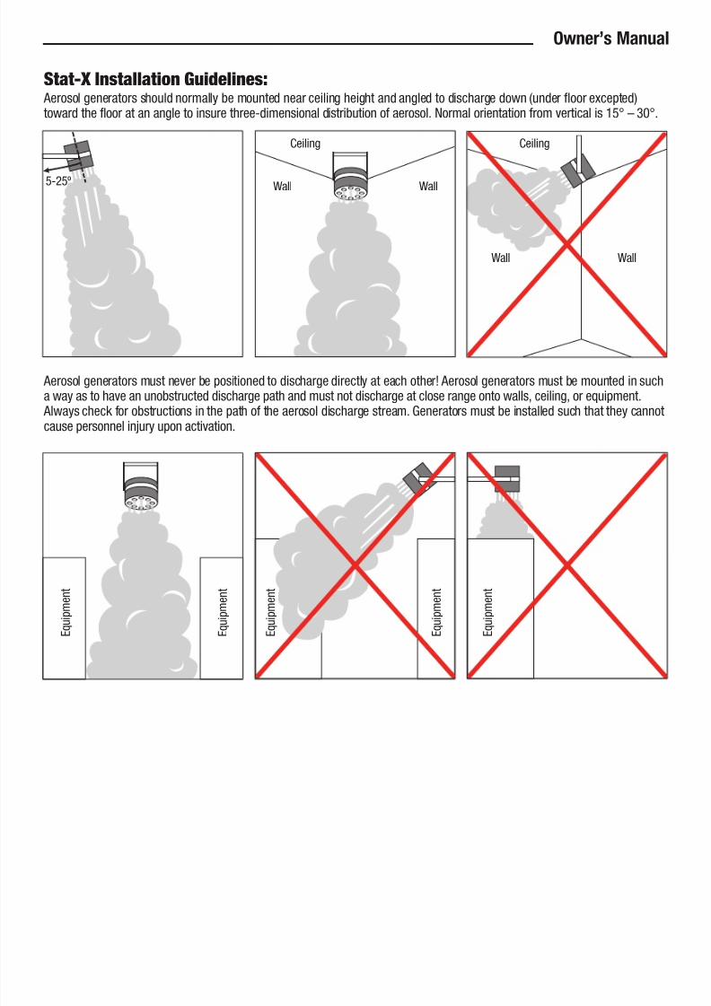
S,!,-X I'+,!%%!,$(' G$"#%$'#+: Aerosol generators should normally be mounted near ceiling height and angled to discharge down (under floor excepted)toward the floor at an angle to insure three-dimensional distribution of aerosol. Normal orientation from vertical is 15° – 30°.
Aerosol generators must never be positioned to discharge directly at each other! Aerosol generators must be mounted in sucha way as to have an unobstructed discharge path and must not discharge at close range onto walls, ceiling, or equipment. Always check for obstructions in the path of the aerosol discharge stream. Generators must be installed such that they cannotcause personnel injury upon activation.
Owner’s Manual
CeilingCeiling
Wall
Wall5-25º Wall
Wall
E q u
i p m e n t
E q u
i p m e n t
E q u
i p m e n t
E q u
i p m e n t
E q u
i p m e n t

7/23/2019 Manual Stat X.PDF
http://slidepdf.com/reader/full/manual-stat-xpdf 12/13
12

7/23/2019 Manual Stat X.PDF
http://slidepdf.com/reader/full/manual-stat-xpdf 13/13
5852 Baker RoadMinnetonka, MN 55345
U.S.A.
Tel: 952-935-9745
Fax: 952-935-9757www.statx.com