Embed Size (px)
Citation preview

IN S T R U C T IO N M A N U A L
Vibration Analyzer PCE-VM 3D
PCE Americas Inc.711 Commerce Way Suite 8 JupiterFL-33458USAFrom outside US: +1Tel: (561) 320-9162Fax: (561) [email protected]
www.pce-instruments.com/englishwww.pce-instruments.com
PCE Instruments UK Ltd.Units 12/13
Southpoint Business Park Ensign way
Hampshire / SouthamptonUnited Kingdom, SO31 4RF
From outside UK: +44Tel: (0) 2380 98703 0
Fax: (0) 2380 98703 9 [email protected]
Manual
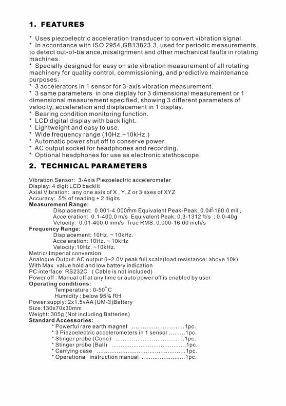
Vibration Sensor: 3-Axis Piezoelectric accelerometerDisplay: 4 digit LCD backlitAxial Vibration: any one axis of X , Y, Z or 3 axes of XYZAccuracy: 5% of reading + 2 digitsMeasurement Range:
Displacement: 0.001-4.000mm Equivalent Peak-Peak; 0.04-160.0 mil , Acceleration: 0.1-400.0 m/s Equivalent Peak; 0.3-1312 ft/s ; 0.0-40gVelocity: 0.01-400.0 mm/s True RMS; 0.000-16.00 inch/s
Frequency Range:Displacement: 10Hz. ~ 10kHz.Acceleration: 10Hz. ~ 10kHzVelocity:10Hz. ~10kHz.
Metric/ Imperial conversionAnalogue Output: AC output 0~2.0V peak full scale(load resistance: above 10k)With Max. value hold and low battery indicationPC interface: RS232C ( Cable is not included)Power off : Manual off at any time or auto power off is enabled by user Operating conditions:
Temperature : 0-50 C Humidity : below 95% RHPower supply: 2x1.5vAA (UM-3)BatterySize:130x70x30mmWeight: 305g (Not including Batteries)Standard Accessories:
* Powerful rare earth magnet .............................1pc.* 3 Piezoelectric accelerometers in 1 sensor .........1pc.* Stinger probe (Cone) ......................................1pc.* Stinger probe (Ball) .........................................1pc. * Carrying case .................................................1pc. * Operational instruction manual ........................1pc.
* Uses piezoelectric acceleration transducer to convert vibration signal.* In accordance with ISO 2954,GB13823.3, used for periodic measurements,to detect out-of-balance,misalignment and other mechanical faults in rotatingmachines.* Specially designed for easy on site vibration measurement of all rotatingmachinery for quality control, commissioning, and predictive maintenancepurposes.* 3 accelerators in 1 sensor for 3-axis vibration measurement.* 3 same parameters in one display for 3 dimensional measurement or 1dimensional measurement specified, showing 3 different parameters ofvelocity, acceleration and displacement in 1 display.* Bearing condition monitoring function.* LCD digital display with back light.* Lightweight and easy to use.* Wide frequency range (10Hz.~10kHz.)* Automatic power shut off to conserve power.* AC output socket for headphones and recording.* Optional headphones for use as electronic stethoscope.
2. TECHNICAL PARAMETERS
1. FEATURES
2 2

3. PARTS INTRODUCTION
Figure 3.1
According to different situations, the transducers maybe fixed in the probe or connected to the magnetic base. (see chapter 4 in detail)4. DISPLAY INTRODUCTION
3-4 3D Vibration Sensor3-5 Bolt3-6 Magnetic Base
3-1 Main Body3-2 Stinger Probe (Cone)3-3 Stinger Probe (Ball)
X
YZ
3D VIBR
ATION SEN
SOR
3-1 3-2 3-3 3-4 3-5 3-6
4-1 3-axis indication4-2 Low battery indication4-3 Z-axis4-4 Velocity4-5 X-axis4-6 Acceleration
4-7 Max value hold4-8 Y-axis4-9 Displacement4-10 4-11 4-12 Auto power off is enabled
Measuring valueMeasuring unit
Figure 4.1
4-34-44-54-64-7
4-8
4-9
4-11
4-14-2
4-10
4-10
SV
SV 4-12
SurfaceVibration sensor
Bolt M5
Object Being tested
√
Ⅹ Thickness 8
The bolt drills through the object being tested
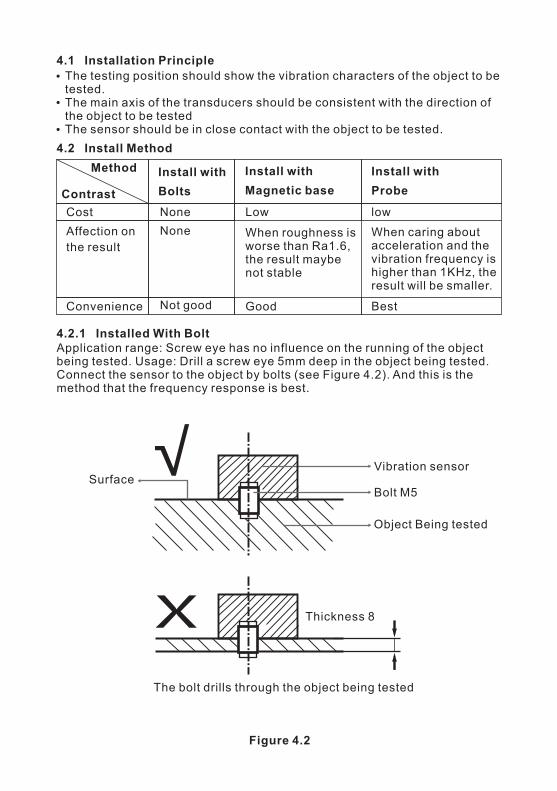
4.1 Installation Principle
The testing position should show the vibration characters of the object to be tested.The main axis of the transducers should be consistent with the direction of the object to be testedThe sensor should be in close contact with the object to be tested.
4.2 Install Method
Affection onthe result
Cost
Convenience
4.2.1 Installed With BoltApplication range: Screw eye has no influence on the running of the object being tested. Usage: Drill a screw eye 5mm deep in the object being tested. Connect the sensor to the object by bolts (see Figure 4.2). And this is the method that the frequency response is best.
Figure 4.2
Method
Contrast
Install with
Probe
lowWhen caring aboutacceleration and thevibration frequency ishigher than 1KHz, theresult will be smaller.
Best
Install with
Bolts
NoneNone
Not good
Install with
Magnetic base
When roughness isworse than Ra1.6,the result maybenot stable
Low
Good

4.2.3 Installed With ProbeApplications Range: Frequency is less than 1KHz and vibration energy is not small. Usage: Connect the needle to the sensor directly by using probe groupware.(see Figure 4.4)
Hold
Vibration sensor
probe/needle
Object being tested
Surface
Forming right angles between the needle and the surface
Ⅹ
The needle makes thesurface distortion
The mass istoo small Forming bevel between theneedle and the surface
4.2.2 Installed With Magnetic Base
Figure 4.3
Application range: Magnetic, flat surface, roughness less than Ra1.6, acceleration less than 20m/ .Usage: connect the vibration sensor with magnetic base with the M5 bolt included. And then place the magnetic base to the object to be tested. Please refer the below.
2s
Vibration transducer
Bolt M5
Magnetic base
Object being tested
Surface
The surface is slick and flat The surface is rough The surface is uneven
Figure 4.4
ⅩⅩ
Ⅹ Ⅹ
√
√

5.1 Connecting the sensora. Note that this meter accepts only the supplied vibration sensor.b. Plug the connector side of the sensor into the plug at the top of the meter.c. The sensor can be connected to the machinery under test in three ways.Please refer the blow.
5.2 Power ON-OFFa. Press the POWER button to turn the meter ON or OFF.b. The meter is equipped with an automatic power off utility that conservesbattery life. If the meter is left inactive for 30 minutes it will automatically turnoff. The automatic power off utility is enabled or disabled by pressing and holdthe volume key for 5s. The symbol ‘SV’ showing on the display indicates autopower off utility is enabled. Otherwise, disabled if not showing ‘SV’.
5.3 How to set coordinate axisThere are 4 choices of X, Y, Z, XYZ. Any one coordinate axis of X or Y or Z with 3 parameters of velocity, acceleration and displacement showing on one display can be selected. Or 3-axis of X-Y-Z with any one parameter of velocity or acceleration or displacement can be selected. The currently selected coordinate axis is shown on the meter’s LCD. Every time to press the X / Y/ Z / XYZ key, the selected axis is changed. Please pay attention to the axes marked on the 3 dimensional sensor. See below.
5. GETTING STARTED
Front ( A ) Z ( C )X ( B ) Y ( D )
5.4 Function SelectionFunction key is only valid in the 3-axis mode and used to select the parameter to be measured. The currently selected parameter is shown on the meter’sLCD. To change the parameter, just press and release the FUNCTION key.ACC means ‘Acceleration’ measurement mode.VEL means ‘Velocity’ measurement mode.DISP means ‘Displacement’ measurement mode.5.5 Unit ConversionThe currently selected unit of measure is shown on the meter’s LCD. To change the unit of measure, press the UNIT key.
Stinger Probe Installed with bolt Magnetic Base
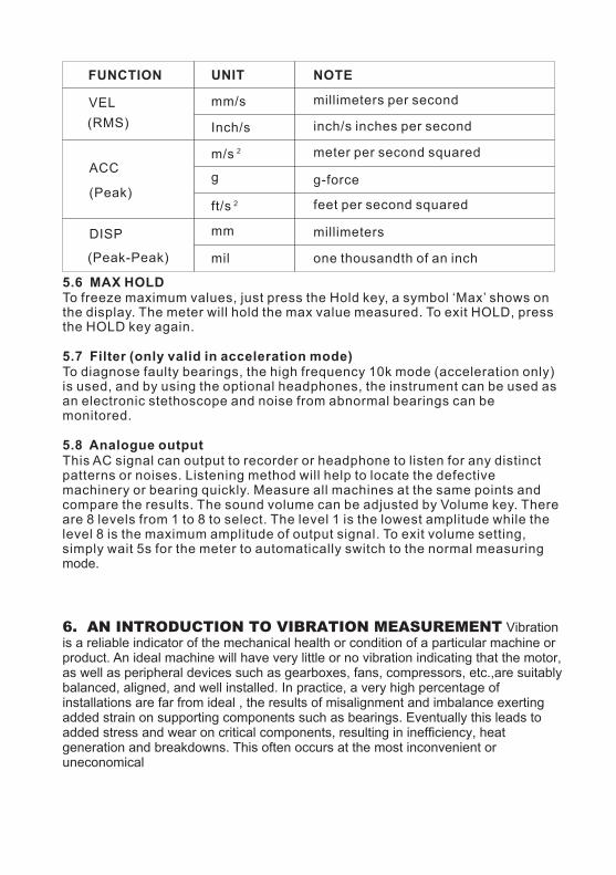
FUNCTION UNIT NOTE
VEL(RMS)
ACC
(Peak)
DISP
(Peak-Peak)
mm/s
Inch/s
g
mm
mil
ft/s 2
m/s 2
millimeters per second
inch/s inches per second
meter per second squared
g-force
feet per second squared
millimeters
one thousandth of an inch
5.6 MAX HOLDTo freeze maximum values, just press the Hold key, a symbol ‘Max’ shows on the display. The meter will hold the max value measured. To exit HOLD, press the HOLD key again.
5.7 Filter (only valid in acceleration mode)To diagnose faulty bearings, the high frequency 10k mode (acceleration only) is used, and by using the optional headphones, the instrument can be used as an electronic stethoscope and noise from abnormal bearings can be monitored.
5.8 Analogue outputThis AC signal can output to recorder or headphone to listen for any distinct patterns or noises. Listening method will help to locate the defective machinery or bearing quickly. Measure all machines at the same points and compare the results. The sound volume can be adjusted by Volume key. There are 8 levels from 1 to 8 to select. The level 1 is the lowest amplitude while the level 8 is the maximum amplitude of output signal. To exit volume setting, simply wait 5s for the meter to automatically switch to the normal measuring mode.
6. AN INTRODUCTION TO VIBRATION MEASUREMENT Vibration is a reliable indicator of the mechanical health or condition of a particular machine or product. An ideal machine will have very little or no vibration indicating that the motor, as well as peripheral devices such as gearboxes, fans, compressors, etc.,are suitably balanced, aligned, and well installed. In practice, a very high percentage of installations are far from ideal , the results of misalignment and imbalance exerting added strain on supporting components such as bearings. Eventually this leads to added stress and wear on critical components, resulting in inefficiency, heat generation and breakdowns. This often occurs at the most inconvenient or uneconomical
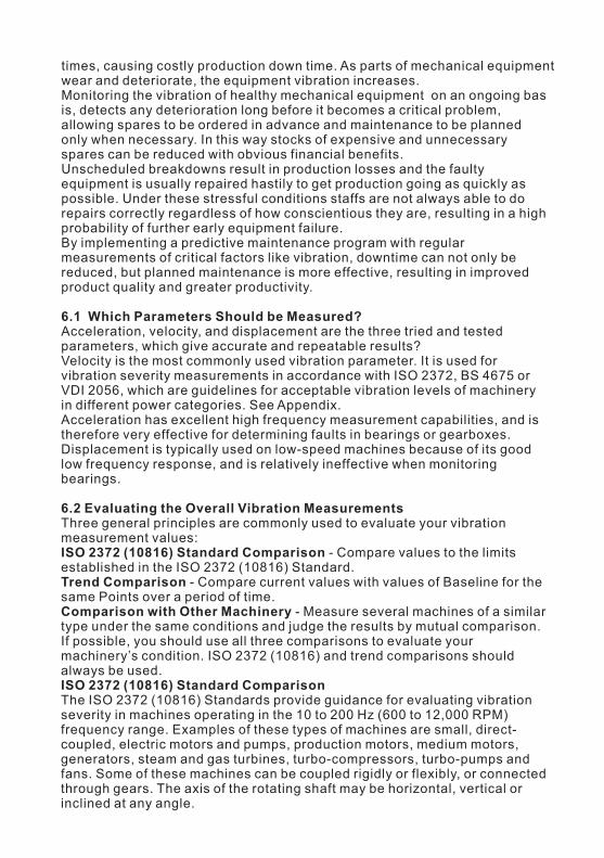
times, causing costly production down time. As parts of mechanical equipment wear and deteriorate, the equipment vibration increases.Monitoring the vibration of healthy mechanical equipment on an ongoing basis, detects any deterioration long before it becomes a critical problem,allowing spares to be ordered in advance and maintenance to be planned only when necessary. In this way stocks of expensive and unnecessary spares can be reduced with obvious financial benefits.Unscheduled breakdowns result in production losses and the faulty equipment is usually repaired hastily to get production going as quickly as possible. Under these stressful conditions staffs are not always able to do repairs correctly regardless of how conscientious they are, resulting in a high probability of further early equipment failure.By implementing a predictive maintenance program with regular measurements of critical factors like vibration, downtime can not only be reduced, but planned maintenance is more effective, resulting in improved product quality and greater productivity.
6.1 Which Parameters Should be Measured?Acceleration, velocity, and displacement are the three tried and tested parameters, which give accurate and repeatable results?Velocity is the most commonly used vibration parameter. It is used for vibration severity measurements in accordance with ISO 2372, BS 4675 or VDI 2056, which are guidelines for acceptable vibration levels of machinery in different power categories. See Appendix.Acceleration has excellent high frequency measurement capabilities, and is therefore very effective for determining faults in bearings or gearboxes.Displacement is typically used on low-speed machines because of its good low frequency response, and is relatively ineffective when monitoring bearings.
6.2 Evaluating the Overall Vibration MeasurementsThree general principles are commonly used to evaluate your vibration measurement values:ISO 2372 (10816) Standard Comparison - Compare values to the limits established in the ISO 2372 (10816) Standard.Trend Comparison - Compare current values with values of Baseline for the same Points over a period of time.Comparison with Other Machinery - Measure several machines of a similar type under the same conditions and judge the results by mutual comparison. If possible, you should use all three comparisons to evaluate your machinery’s condition. ISO 2372 (10816) and trend comparisons should always be used.ISO 2372 (10816) Standard ComparisonThe ISO 2372 (10816) Standards provide guidance for evaluating vibration severity in machines operating in the 10 to 200 Hz (600 to 12,000 RPM) frequency range. Examples of these types of machines are small, direct-coupled, electric motors and pumps, production motors, medium motors,generators, steam and gas turbines, turbo-compressors, turbo-pumps andfans. Some of these machines can be coupled rigidly or flexibly, or connectedthrough gears. The axis of the rotating shaft may be horizontal, vertical or inclined at any angle.

6.3 Measurement TechniquesIn general, vibration of anti-friction bearings is best monitored in the load zone of the bearing. Equipment design often limits the ability to collect data in this zone. Simply select the Measurement Point which gives the best signal. Avoid painted surfaces, unloaded bearing zones, housing splits, and structural gaps. When measuring vibration with a hand-held sensor, it is very important to collect consistent readings, paying close attention to the sensor’s position onthe machinery, the sensor’s angle to the machinery, and the contact pressure with which the sensor is held on the machinery.. Location - always collect at the same point on the machine. Mark locations.. Position - Vibration should be measured in three directions:A axial direction; H horizontal direction; V vertical directionPlease define A, H, V as X, Y, Z axes respectively.. Angle - Always perpendicular to the surface (90°±10°).. Pressure - Even, consistent hand pressure must be used (firm, but not so firm as to dampen the vibration signal). For best results ,use the magnetic base. If using the stinger/probe is the only method available to collect data, it is best to use a punch to mark the location for the probe-tip to ensure a consistent coupling to the housing.
7.1 When the battery symbol appears on the display, it is time to replace the battery.7.2 Slide the Battery Cover away from the instrument and remove the batteries.7.3 Install batteries paying careful attention to polarity.
7. BATTERY REPLACEMENT
A. Rank of machine vibration (ISO 2372)
VibrationAmplitude
Vibration
VelocityV rms (mm/s)
0~0.280.28~0.450.45~0.710.71~1.121.12~1.81.8~2.82.8~4.54.5~7.1
7.1~11.211.2~1818~2828~45>45
AA
AA
BB
BB
CC
CC
DD
DD
Machine sort
I II III IIII
8. APPENDIX: VIBRATION STANDARDS

Limit of rank “N” is suitable for common motor. When the request is higher than that in the table, limit can be gotten by dividing the limit of rank 'S' with 1.6 or multiples of 1.6.
Note: (1)“Class I” is small motor ( power less than 15 kw). “Class II” is medium motor (power between 15 ~75kw). “Class III” is high power motor (hard base).“Class IIII” is high power motor (stretch base).(2)A,B,C,D are vibration Rank. “A” means good, “B” means satisfying, “C”means not satisfying, “D” means forbidden. Vibration velocity should be takenfrom the three perpendicular axes on the motor shell.B. ISO/IS2373 Motor quality standard according as vibration velocity
Quality
rankRev (rpm)
Normal
Good ( R)
Excellent (S)
600~3600600~1800
1800~3600600~1800
1800~3600
H: high of shaft (mm)
Maximum vibration velocity (rms)
(mm/s)
80<H<132
4.51.82.8
1.121.8
1.80.711.120.450.71
2.81.121.80.711.12
132<H<225 225<H<400
C. Maximum vibration of motor that power larger than 1 horsepower.(NEMA MG1-12.05)
Rev (rpm)
3000~40001500~29991000~1499
≤999
25.438.150.863.6
Displacement
(P-P) (um)
For AC motor, rev is maximum synchronous rev. For DC motor, it is maximum power rev. For motor in series, it is work rev.D. Maximum vibration of high power induction drive motor.(NEMA MG1-20.52)
National Electric Manufacturers Association (NEMA)Establishes two standards above.
Rev (rpm)
≥30001500~29991000~1499
≤999
25.450.863.676.2
Displacement
(P-P) (um)

Triple
E. Troubleshooting
1. Eccentric of gear, beltsheave and bush.2. Shaft is not in the middleor curving (if vibration on the shaft direction is high).3. Belt fault4. Syntony5. Reciprocate force
Vibrationfrequency
Most possiblereason
Other possible reason Note
ImbalanceSynchronous
with *
1. Shaft is not in the middleor curing ( if vibration onthe shaft direction is high).2. Belt fault3. Syntony4. Reciprocate force
Double Mechanical loose
Not in middle
If loose is worse,there maybehigher multiplefrequency.
Gear fault, liquidforce, mechanicalloose, reciprocatingforce.
f s1 x N x ( N is the toothnumber of the fault gear ).2 x N x ( N is the paddlenumber of the fault pump or fan ).
f s
f s
f s
f s
N multiple off s
1. Drive belt fault2. Interferential vibration3. Beat frequency
Oil film eddyturbulencef s
Synchronous with power frequency
Armature fault
Electric fault such as rotor broken, rotor eccentric, there phase imbalance and air clearance not symmetry.
Double the powerfrequency Torsional impulse Seldom
High frequency( not multiple of )f s
Shaft is not lubricate
1. Cavitations andturbulent flow.2. Frictional force.
Amplitude and frequency of vibration are always not steady
* Is the frequency according with the rev of main shaft.