Embed Size (px)
Citation preview
USER INSTRUCTIONS
SIRIO315+370ing ED.2009 rev.00 1/45
IMET Spa
Loc. Tre Fontane - Cisano Bergamasco Tel. 035/4387911 - Fax. 035/787066 Web site: www.imetsaws.com E-mail: [email protected]
Manual Metal Cutting Circular Saws, vertical slide type SIRIO 370, SIRIO 315
USER’S INSTRUCTIONS
USER INSTRUCTIONS
SIRIO315+370ing ED.2009 rev.00 8/45
1-
We recommend to read carefully the information here included in order to install, use and maintain correctly and safely
this machine.
Please refer always to this instruction manual in case of assistance service need and keep it carefully for all the
machine life. The reference number in Italy is +39 035 4387918 or +39 035 4397928.
A consequence of the continuous improvement of the product is that some images/descriptions here included could not
correspond to the improved features of the machines.
Your kind collaboration would help us in intevening asap.
In the enclosed Compliance Declaration you will find the Safety and Reference Norms applied during the planning and
construction of this machine.
The choice and the use of the parts have been made by considering the conditions of use and the long machine life.
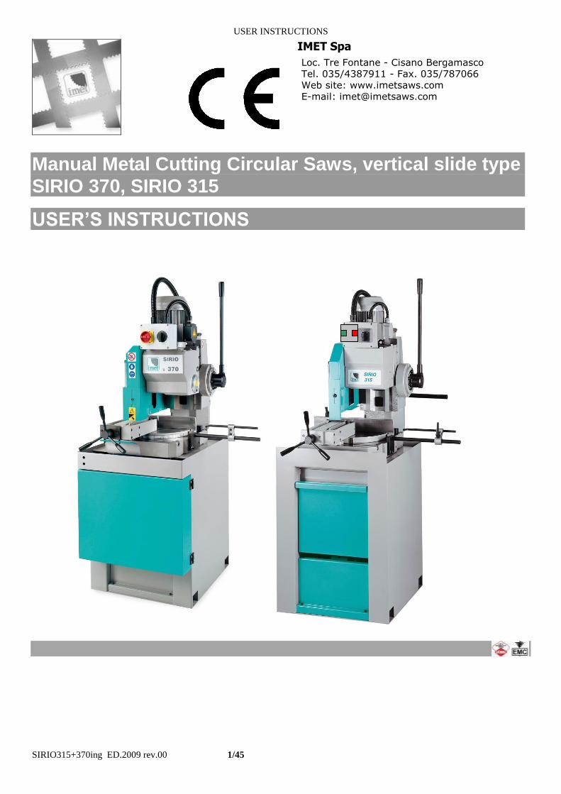
The identification plate, with the serial number, is fixed on the front right angle of the base or on a wall of control box.
1.1 - ATTACHED DOCUMENT FOR E.M.C. ( INDUSTRIAL ENVIRONMENT) The user is responsible for installation and use of this machine in compliancewith the manifacturer's
instructions shown in this manual. This plant meetsthe protection requirements in accordance with the Directives 2006/42/EC,
And2004/108/EC as for electromagnetic compatibility (EMC). In particular, it follow the technical instructions of the Rules EN55011,EN50082-2 and it has been realized
for industrial and not for household use. In the event that should be electromagnetic interferences the user is responsible for solving the problem
together with the technical assistance of the manifacturer. Before installing the machine the user must take into account possible electromagnetic problems of the
working area. In particular, we suggest installing the plant away from: -signalling, control and telephone cables; -radiotelevision transmitters and receivers; -computers or controlling and measuring instrument; -safety and protection devices.
The electric supply cable must be kept as short as possible, well right and without wires. The covers, the door and the frame must be suitably closed when the plant is operating.
Under no circumstances the plant must be modified except for adjusting and changing established by the manifacturer. Follow the maintenance schedule
USER INSTRUCTIONS
SIRIO315+370ing ED.2009 rev.00 9/45
2
|-------------------------------------------------------------------------------------------------------------------------------|
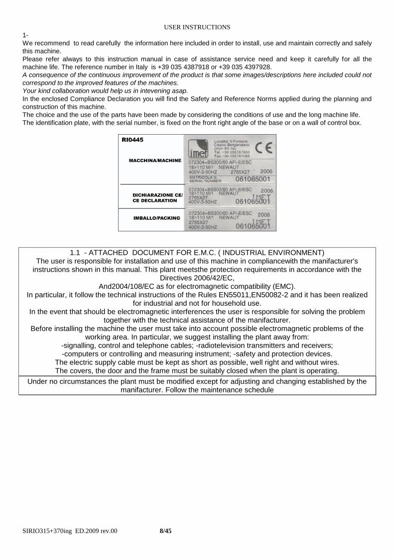
CE DECLARATION OF CONFORMITY (encl. II A DIR 2006/42/CE) / 02
|-------------------------------------------------------------------------------------------------------------------------------|
according to the law that transposes the Machine Directives
THE MANUFACTURER : IMET S.p.A
Località Tre Fontane
24034 - CISANO BERGAMASCO –BG- ITALIA
HEREBY DECLARES THAT
in designing and manufacturing the machine described here below , we have considered the most important
requirements of safety and health dictated by the European Directives of the Machine Security.
Remember that this declaration loses its validity if machine is modified without our agreement.
SEMIAUTOMATIC CIRCULAR SAWING MACHINE FOR METALS
Code / Model / Type
Manufacturing year
Serial number
IT IS IN COMPLIANCE WITH THE DIRECTIVES
DIRECTIVE 2006/42/CE OF THE EUROPEAN PARLIAMENT AND OF THE COUNCIL OF THE 17TH/05/2006 REGARDING THE MACHINES AND THAT MODIFIES THE DIRECTIVE 95/16/CE; DIRECTIVE 2004/108/CE OF THE EUROPEAN PARLIAMENT AND OF THE COUNCIL OF THE 15/12/04 REGARDING THE ELECTROMAGNETIC COMPATIBILITY -EMC- DIRECTIVE 2006/95/CE OF THE EUROPEAN PARLIAMENT AND OF THE COUNCIL OF THE 12/12/06 REGARDING ELECTRICAL EQUIPMENT FOR USE OF LOW VOLTAGE -LVD- HARMONIZED STANDARDS REFERENCE EN.12100-1, EN12100-2; EN 55011, EN50082-2, EN 13898, EN 60204 LEGISLATIVE DECREE N.17 OF THE 27TH OF JANUARY 2010.
AND AUTHORIZING THE PERSON LISTED BELOW TO ISSUE THE TECHNICAL FILE.
Date : 01.01.2010
The signatory identification The manager
Angelo Meroni
------------------------------------------------------------------------------------------------------------------------
File : Machine no. Delivery note no dated
------------------------------------------------------------------------------------------------------------------------
ORIGINAL DECLARATION IS AT THE MACHINE
USER INSTRUCTIONS
SIRIO315+370ing ED.2009 rev.00 10/45
3 - MACHINE NOISE
The decibel pointed out in the workplace in the conditions under described is appointed to the simoultaneous working of
some machine parts in motion ( it depends on the detailed cycle ) added to that one of the tool when is cutting the
workpiece.
In several moments the decibel are pointed out to note the different using conditions.
The phon-meter is placed at about 1 meter near the machine and at about 1,60 m from the floor.
The results of each test is in dBA and they mean the average of 3 tests made from the: left side, opposite side,
right side.
For any machines the using conditions are the following :
When idle, at the maximum blade speed: dBA 63
During the cut, at a suited blade speed, cutting solid steel (St12=≈C20, 80mm diameter): dBA 75
(tolerance ± 2dB).
In the standard production the test is made by a same machine of above mentioned one, in compliance with E.C.
safety norms 2006/42/EC .
The use of the machine in bad conditions or the use of the wrong tools cause also sensitive alterations of these tests
and it is prejudicial for the health of the taff and for the good results of the work .
Most of all the noice depends on the cutting material, on its sizes and on the locking system. By expecting that above mentioned decibels could be exceeded, we recommend the operator the using of the personal means of protection ( head phones, plugs etc. ) in case of working a long time at highest levels, taking into account other possible machinery running nearby and the characteristics of the working place
3.1 - ADDITIONAL HEALTH AND SAFETY REQUIREMENTS
This type of machine, manually controlled during some working operations, must respond to further health and safety requirements as specified by article 2.2 of the Annexed I of the European Directive 2006/42/ECand following. In particular, the level of vibrations emitted by the machine while in use must be clearly specified in the instructions.
This machine does not emit vibrations of a level higher than 2,5 m/s 2 The measurement procedure used conforms to the general norms applied to this type of machine.
As in the preceding paragraph, using the machine in unsuitable conditions or using the wrong tools can cause
changes affecting this value, endangering the health of the work force as well as the quality of production.
Vibrations emitted during cutting may be amplified by the material, by its dimensions and its
positioning/clamping in the vice.
USER INSTRUCTIONS
SIRIO315+370ing ED.2009 rev.00 11/45
4 - GUARANTEE NORMS
I.ME.T. offers a wide range of sawing machines and accessories, destined to who buys/uses them as part of a
commercial or professional activity.
The manufacturer grants that this product has been strongly controlled and that there are no defects in the used and
working materials for a period of 12 months from the date of the delivery note.
The italian law D.L. n° 24 issued on 02/02/2002 and valid since 23/03/2002 (which carries out the European Directive
1999/44/CE) indicates different terms only for convenience products for private use.
If the user points out some defects to the manufacturer during the warranty time, the manufacturer will replace the
components that are considered defected.
In case of reparation of the machine during the warranty time the shipment will be accepted only if the delivery is Free
Destiny (that is the freight costs are supported by the owner of the machine), and the return of the machine to the
customer is considered EX WORKS.
If the manufaturer is not able to remplace a component within an acceptable time, both companies (manufacturer and
user) will reach an agreement for satisfying completely the needs of the user.
The a.m. warranty is not valid in case of accidental damages, or defects provoked by a wrong use of the machine or
maintenance, by variations made on the machine, or by the use of the machine in a place not corresponding to the
indicated enviromental specifications.
4.1 - The manufacturer does not offer further warranties, written or spoken, explicit or implicit of its products and does
not offer implicit warranties on saleability or adequacy for particular uses not foreseen by the agreement.
The a.m. limitations and exclusions can also be not applicable in Countries, where there are no implicit limits of
warranty time on the products. Anyway each implicit warranty is limited to a time of 12 months from the date of the
delivery note.
4.2 - The date of manufacture, deducible from the serial number placed on the machine, is a very necessary reference
for the warranty, for the assistance after-sale and for the identification of the product.
Each tampering on the products, expecially the installation of safety devices, will relieve the manufacturer of any kind of
responsability.
The parts most subject to rapid and continuous wear are not included in the warranty (for example: transmission belts,
gaskets, oils, blades, and so on).
For the electrical, electronic and hydraulic equipments and for the other equipments having its own individuality (of
which there is the possibility to know the name of the constructor), the manufacturer gives to the user the same
warranty received by the primary constructor of these parts.
4.3 - The components replaced during the assistance operated by the manufacturer have a warranty of 6 months from the installation date indicated on the Technical Service paper, one copy of which is given to the owner.
USER INSTRUCTIONS
SIRIO315+370ing ED.2009 rev.00 12/45
5 - SUMMARY pag.
1- PREMESSA 2
2 – CONFORMITY DECLARATION 3
3 – AIR NOISE 4
4 – GUARANTEE NORMS 5
5 – Index 6
6 – Technical characteristics 7
7 – Installation – minimum requirements 9
8 – Moving and transit 9
9 – Fittings/optionals 11
10 – Blade choice 12
11 – Foreseen use and controindications 14
12 – Machine description 17
13 – Work preparation 18
14 – Blade mounting 19
15 – Functioning 20
16 – Regulations 25
17 – Maintenance – for the user 27
18 – Band running-in 28
19 – Machine running-in 28
20 – Draining of used/produced substances 29
21 – Trouble-shooting 29
22 – Machine demolition 31
23 – Spare parts 32
24 – Maintenance – for qualified technicians 33
Electrical drawings
Hydraulic diagram
Spare Parts drawings
-
USER INSTRUCTIONS
SIRIO315+370ing ED.2009 rev.00 13/45
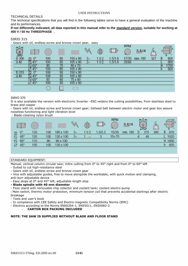
TECHNICAL DETAILS
The technical specifications that you will find in the following tables serve to have a general evaluation of the machine
and its performances.
If not differently indicated, all data reported in this manual refer to the standard version, suitable for working at
400 V / 50 Hz THREEPHASE .
SIRIO 315 - Gears with oil, endless screw and bronze crown gear, easy
SIRIO 370 It is also available the version with electronic Inverter –ESC-widens the cutting possibilities, from stainless steel to brass and copper - Gears with oil, endless screw and bronze crown gear; totheed belt between electric motor and gear box assure noiseless functioning and light vibration level - Blade-cleaning nylon brush
STANDARD EQUIPMENT:
Manual, vertical column circular saw; mitre cutting from 0° to 45° right and from 0° to 60° left - Suited to cut high-resistance steel
- Gears with oil, endless screw and bronze crown gear - Vice with adjustable guides, free to move alongside the worktable, with quick motion and clamping, anti-burr adjustable device - Easy stops at 0° and 45° left, adjustable length stop - Blade spindle with 40 mm diameter - Floor stand with removable chip collector and coolant tank; coolant electro-pump
- Main switch, thermic motor protection, minimum tension coil that prevents accidental startings after electric
breakage - Tools and user’s book - In compliance with CEE Safety and Electro-magnetic Compatibility Norms (EMC) - Electrics according to the Norms EN60204-1, EN55011, EN50082-2
- CARTON BOX PACKING INCLUDED
NOTE: THE SAW IS SUPPLIED WITHOUT BLADE AND FLOOR STAND
USER INSTRUCTIONS
SIRIO315+370ing ED.2009 rev.00 14/45
7 - INSTALLATION
The machine can work according to the parameters provided by the manufacturer if it is rightly installed and the
minimum requirements are observed, as follows :
- Machine must be used indoor and with temperatures from +5 to + 40 ° C.
- The relative humidity of the environment must not go over 95%.
- The nominal value of the voltage of electric energy must be between + - 10 and the frequency of the nominal value
must be between + - 2%.
The floor must have good characteristiques of capacity and level.
Floor space, operator position and working area are indicated in the included drawing that concerns the machine only
without fittings as optional.
Work table must be leveled: by using the screws and nuts (NOT SUPPLIED) put in the little feet holes to FIX the
machine to the floor .
The included electrical schemes reproduces the necessary details to arrange the connections, to be
predisposed for 4 KW power request,.
. Earthing of all the electric parts with a dedicated GREEN/YELLOW wire, connected with a TN system to the supply cable. A supplementary earthing point – indicated with PE – can be located on the metallic structure of the machine
N.B.
Be careful with cables protruding from upper part of machine when you are lifting it. Fix between them the machine and
the floor stand by using the 4 socket screws supplied together to the current fittings ( do not use those employed for the
packing ). The nuts are already in the using position.
The tank and the electropump must be desplaced from the base and placed inside the floor stand trough the back
opening; to do this , it is necessary to remove the chip tray taking out it from the front side of base.
The cables that come out from the back side of the machine must be inserted in the floor stand; then the supply cable
must be inserted ( form inside to outside ) in the pressing cable ( and locked ) before the connection to the line.
Connect the cooling pipe to the cock placed on the carter of the machine.
If there are other parts as pneumatic vice they must be connected from the customer’s pipe of compressed air to the
plug placed onto valve, near the control lever of up/down. stroke
7.1 - DIFFERENTIAL PROTECTION
For the connection of the differential protection on the power supply line it is necessary to use switches with a
threshold of interference on the power dissipation of not less than 300 mA (size 0.3 A or higher is
recommended), having possibly time adjustment availability (0>1.5 sec).
E.M.C. Electromagnetic noise
This machine has been foreseen for industrial and not for household use. In the event that should be electromagnetic
interferences the user is responsable for solving the problem together with the technical assistance of the manufacturer.
Before installing the machine the user must take into account possible electromagnetic problems of the working area. In
particular we suggest to install the plant away from:
- signalling, control and telephone cables;
- radiotelevision transmitters and receivers;
- computers or controlling and measuring instruments;
- safety and protection devices.
The electric supply cable must be kept as short as possible, well right and
without wires.
The covers, the door and the frame must be suitably closed when the plant is operating.
Under no circumstances the plant must be modified except for adjusting and
changing established by the manifacturer. Follow the maintenance schedule.
8 – TRANSPORT & LIFTING For the transport of the machine only the methods indicated below are possible. However, be sure that the means of transport snd lifting are able to stand the machine's weight and its packing (about 500 Kg):
USER INSTRUCTIONS
SIRIO315+370ing ED.2009 rev.00 15/45
WARNING The personnel in charge of loading, unloading and moving the machines should use protective gloves.
WARNING
When lifting or moving the machine, or a part of it, take care of clearing the operations area of the people, considering
also an appropriate safety area around it, so as to avoid any risks of injuring people or damaging things located nearly. Special packings – wooden crate , wooden case –may be predisposed on request, by charge.
ALL THE OPERATIONS THAT INVOLVE MOVING THE MACHINE MUST BE CONDUCTED WHILE RESPECTING
THE FOLLOWING BASIC RULES: + When moving the machine, an appropriate means has to be used, with a loading capacity higher than the weight to
lift, which is indicated on the machine.
+ When choosing and then using equipment such as ropes, chains or lifting belts, be careful about their geometry during the lifting and about the consequent actual loading capacity.
+ The machine is structured so as to offer lifting points, which are appropriately indicated and will have to be used for lifting it.
+ In case the lifting belts touch parts of the machine, nylon belts are required; ropes or chains wrapped with jute or clean covering can also be used. A great care is necessary while slinging and moving the machine in order to hinder damages.
+ All operations have to be conducted with graduality, so as to avoid jolts and dangerous situations.
+ The person in charge of the operations has to make sure that all the national, local and company norms in reference to injury prevention and work safety are respected.
+ Onr or more areas for material storage have to be identified.
After unpacking , unscrew the 4 screws of the fixing feet near the base of the machine unit.
Use the iron plate already fixed to the highest part of the machine to lift it up.
The weight is shown on the packing outside and in the technical data of this manual book also -see par.2- ( it concerns
the total weight : only the floor stand weight is 120 kg. about).
Be sure that lifting tools are proper for the weight and that the moving is correctly made without unbalancing the
machine.
In case of following manipulations, the machine should be displaced with the saw frame completely down and fixing the
turntable to avoid rotations of the parts. Do not use the control box to lift the machine up. Desplace the machine from
floor stand in case of instability.
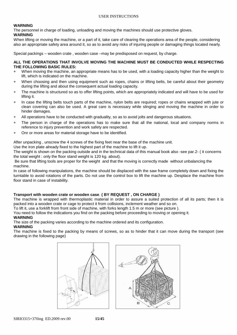
Transport with wooden crate or wooden case. ( BY REQUEST , ON CHARGE ) The machine is wrapped with thermoplastic material in order to assure a suited protection of all its parts; then it is packed into a wooden crate or cage to protect it from collisions, inclement weather and so on. To lift it, use a forklift from front side of machine, with forks length 1.5 m or more (see picture ). You need to follow the indications you find on the packing before proceeding to moving or opening it.
WARNING The size of the packing varies according to the machine ordered and its configuration.
WARNING The machine is fixed to the packing by means of screws, so as to hinder that it can move during the transport (see drawing in the following page)
USER INSTRUCTIONS
SIRIO315+370ing ED.2009 rev.00 16/45
9 – FITTINGS / ACCESSORIES
The information necessary for the installation are given together with the fittings. Anyway you can find here following a
short description of the product.
Supporting roller tables: for installing these accessories in the right way it is necessary first of all to level and fix the
machine. These can be connected on both sides (loading / unloading).
Take as reference point the worktable and the support back jaw in order to aligne the roller tables starting from the one
that is nearest to the machine. If you need very long pieces fix the legs of the roller tables on the ground and recycle
the coolant transported by the workpieces that have to be cut.
If your working process require it, on the unloading side you can choose to use the roller table with manual measuring
system (RTM) or the one with digital measuring system (RTD) also. This last have to be synchronized to the machine
control-that gives automatic desplacement of material stop plate- by an optional device.
" V " jaws - necessary to rightly lock the pipes until 85 mm. of diameter by avoiding the deformation. They allow to
increase the penetration speed by reducing the working time .
They can only make you cuts at 0°, standard minimum length of cutting piece is 35 mm.
Make the holes, if necessary, by using the template included in the assembling kit (only if supplied after selling) ;
assemble them by following the instructions and place them into line by using for example a straight round, to guarantee
a right passage of the bars. During the cut they are progressively shaped by the blade: if your working process don’t
require a complete cut, leave them attached one to the other.
Pneumatic front vice -by the standard furniture the opening / closing system is synchronized to the up / down
movement of the gear head. The locking cylindre comes out a stroke of 7 mm about. For retrofitting ask to the Service
Assistence.
Vertical pneumatic vice –only in case the front pneumatic vice is supplied- It is connected directly to the line that goes
to the frontal vice and it allows to lock the piece also from the upper side. It is recommended to cut more pieces when
you put them side by side on the working table.
Standard adjustable bar stop - fixed on the right side , it is necessary to make more cuts with the same lenght.
Blade speed variator ESC - this electronic device is an inverter that change continuously the revolution speed of blade
motor and allows to cut a lot of different materials, from light alloys to hardened and inox steel.
You can adjust the required speed by the pushbuttons of -1 or +2 speed on the control box. This device can save the
blade from breakage, encreasing its life because stops motor immediately when electrical absorbtion exceeds the
rated value. This optional has to be specified when you ordering the machine.
If requested electric current is more than the inverter is setted it stops immediatly, saving gear head transmission and
belt inside: usually it is caused by the extreme cutting strain, by the too high speed start-up and so on .
Switch the main switch off, wait for about 1 minute before starting it again
Voltage transformer - set it between the electric equipment of the building and the electric supply of the machine. It
allows to work with a different voltage than the standard one (that is 400V ). Available voltages are 230V, 460V ,575V.
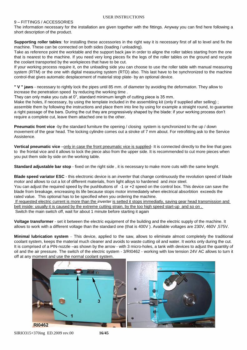
Minimal lubrication system – This device, applied to the saw, allows to eliminate almost completely the traditional
coolant system, keeps the material much cleaner and avoids to waste cutting oil and water. It works only during the cut.
It is comprised of a PIN-nozzle –as shown by the arrow - with 3 micro-holes, a tank with devices to adjust the quantity of
oil and the air pressure. The switch of the electric system - 3/RI0462 - working with low tension 24V AC allows to turn it
off at any moment and use the normal coolant system.
USER INSTRUCTIONS
SIRIO315+370ing ED.2009 rev.00 17/45
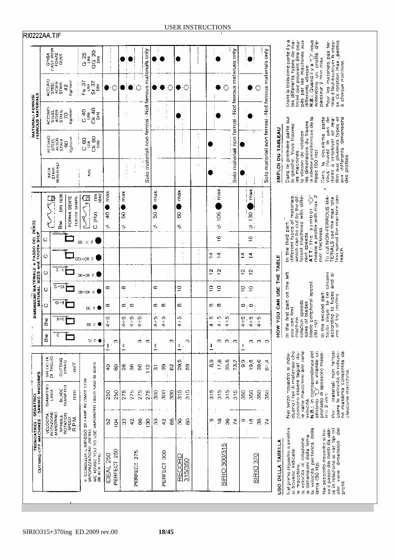
10 - BLADE CHOICE
In this paragraph we suggest the type of blade to use for cutting and the material that must be worked. To get the best
performance from this machine it is necessary to understand the right applications of the used tools and what you have
not to do with them.
The blade you have to use must have the following dimensions (in mm.):
external diameter = 370 max./300 min. ( for SIRIO 370)
hole dia. 40 ; thickness = from 2 to 3
2 holes for the driving pin = d.10 x 63 or d. 12 x 64
P.S. You can get the maximum cutting sizes by using the blade of maximum diameter.
For making a right cut it is also necessary to establish the pitch ( t ) or the suitable number of teeth ( z ). The
blade must usually have the toothing as follows:
- close toothing (little teeth) for cutting thin materials, tubular and profiles.
- thin toothing (big teeth) for cutting solid materials or pieces that need a long piece of blade (for example the central
part of a “U” profile ), or more soft materials as aluminium, copper, soft bronze.
By choosing the right one you can avoid a lot of working errors and you can get a good blade penetration and the
necessary space for the chips.
If you cut more pieces at the same time, you must consider them as one piece (that is you have to consider the
global size).
The enclosed table shows the necessary information for a right choice. It can also be updated or changed by the
user according to his personal experiences
USER INSTRUCTIONS
SIRIO315+370ing ED.2009 rev.00 18/45
USER INSTRUCTIONS
SIRIO315+370ing ED.2009 rev.00 19/45
11. INSTRUCTIONS FOR USE AND WARNINGS
MANUAL MODEL 11.1 - This machine is designed and manufactured so as to be safely used by the operator, provided that it is
properly operated . No protections will ever suffice if the operator does not work with due caution, does not make sure that the machine is in top operating conditions and does not follow the instructions below. You must remember that the machine is designed to CUT METALS with a sharp tool, and you are responsible to see that it is operated in a SAFE and CORRECT manner. 1. make sure that the machine is properly installed and electrical installation is proper. 2. be sure you are familiar with all operating, safety, and applications information before running this saw. 3. see that all who operate this machine are properly trained and fully aware of all safety practices. 4. do not expose yourself or other people to any risk. 5. insist on proper personal protective equipment and practices. 6. maintain all factory-installed SAFETY DEVICES and make sure that these are never removed or altered or restricted in any way. 7. the operator must have a safe and organized work area with suitable light and operating room. 8. the whole equipment has to be correctly and constantly maintained and inspected on a regular basis. 9. never use tools with different features from those for which the machine is designed for. 10.never use this machine to cut material bigger than the cutting capacity. 11. keep the cutting area clear of tools or other loose objects. 12. never operate the saw unless all protections are in place. 13. NEVER WEAR loose clothing, long sleeves, large gloves, jewelry, or any other items that may be trapped into a part of the equipment. Confine long hair. 14. always disconnect the power at source when performing maintenance or making adjustments. 15. never insert hands or arms into or near the cutting area while machine is running. 16. properly clamp the material in the vice and never hold it with your hands. 17. support suitably the bar on both sides of the machine to prevent falling.
We recommend to connect an unloading table in case the cutting length of the material is longer than the distance between the blade and the right edge of the saw.
18. when cutting very short pieces, make sure they do not jam into the blade. 19. if the blade becomes jammed, turn immediately off the motor, then move the cutting unit to the CUTTING START position. If this is not possible, open the vice and move the piece, check that the blade or teeth are not broken, if so replace it. 20. never change the working conditions when cutting, use a controlled downfeed force 21. do not move the saw while cutting and avoid its instability. 22. wear personal safety equipment, if required for a safe operation.
ALWAYS OPERATE THE MACHINE SAFELY, USING COMMON SENSE AND ALERTNESS
USER INSTRUCTIONS
SIRIO315+370ing ED.2009 rev.00 20/45
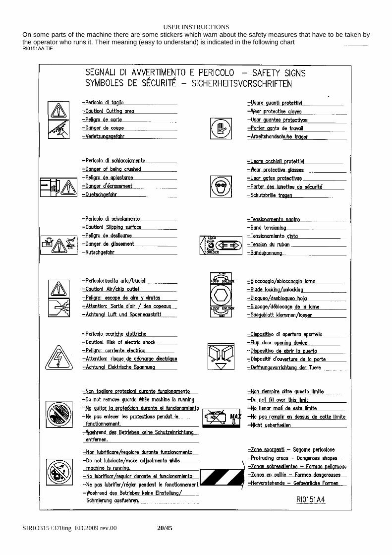
On some parts of the machine there are some stickers which warn about the safety measures that have to be taken by the operator who runs it. Their meaning (easy to understand) is indicated in the following chart
USER INSTRUCTIONS
SIRIO315+370ing ED.2009 rev.00 21/45
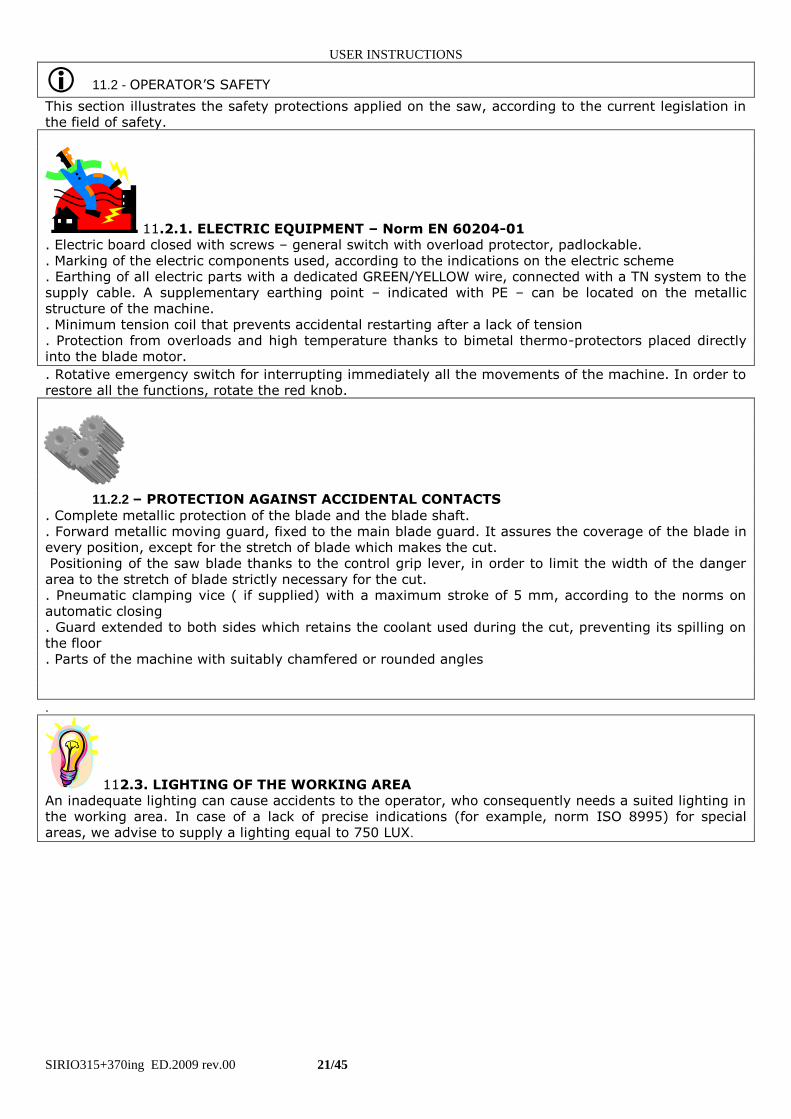
11.2 - OPERATOR’S SAFETY
This section illustrates the safety protections applied on the saw, according to the current legislation in the field of safety.
11.2.1. ELECTRIC EQUIPMENT – Norm EN 60204-01 . Electric board closed with screws – general switch with overload protector, padlockable. . Marking of the electric components used, according to the indications on the electric scheme . Earthing of all electric parts with a dedicated GREEN/YELLOW wire, connected with a TN system to the supply cable. A supplementary earthing point – indicated with PE – can be located on the metallic structure of the machine. . Minimum tension coil that prevents accidental restarting after a lack of tension . Protection from overloads and high temperature thanks to bimetal thermo-protectors placed directly into the blade motor.
. Rotative emergency switch for interrupting immediately all the movements of the machine. In order to restore all the functions, rotate the red knob.
11.2.2 – PROTECTION AGAINST ACCIDENTAL CONTACTS
. Complete metallic protection of the blade and the blade shaft.
. Forward metallic moving guard, fixed to the main blade guard. It assures the coverage of the blade in every position, except for the stretch of blade which makes the cut. Positioning of the saw blade thanks to the control grip lever, in order to limit the width of the danger area to the stretch of blade strictly necessary for the cut. . Pneumatic clamping vice ( if supplied) with a maximum stroke of 5 mm, according to the norms on automatic closing . Guard extended to both sides which retains the coolant used during the cut, preventing its spilling on the floor . Parts of the machine with suitably chamfered or rounded angles
.
112.3. LIGHTING OF THE WORKING AREA An inadequate lighting can cause accidents to the operator, who consequently needs a suited lighting in the working area. In case of a lack of precise indications (for example, norm ISO 8995) for special areas, we advise to supply a lighting equal to 750 LUX.
USER INSTRUCTIONS
SIRIO315+370ing ED.2009 rev.00 22/45
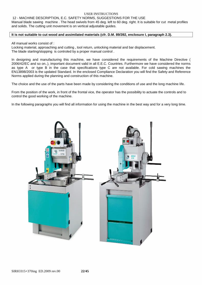
12 - MACHINE DESCRIPTION, E.C. SAFETY NORMS, SUGGESTIONS FOR THE USE
Manual blade sawing machine . The head swivels from 45 deg. left to 60 deg. right. It is suitable for cut metal profiles
and solids. The cutting unit movement is on vertical adjustable guides.
It is not suitable to cut wood and assimilated materials (cfr. D.M. 89/392, enclosure I, paragraph 2.3).
All manual works consist of :
Locking material, approaching and cutting , tool return, unlocking material and bar displacement.
The blade starting/stopping is controled by a proper manual control .
In designing and manufacturing this machine, we have considered the requirements of the Machine Directive (
2006/42/EC and so on..), important document valid in all E.E.C. Countries. Furthermore we have considered the norms
as type A or type B in the case that specifications type C are not available. For cold sawing machines the
EN13898/2003 is the updated Standard. In the enclosed Compliance Declaration you will find the Safety and Reference
Norms applied during the planning and construction of this machine.
The choice and the use of the parts have been made by considering the conditions of use and the long machine life.
From the position of the work, in front of the frontal vice, the operator has the possibility to actuate the controls and to
control the good working of the machine.
In the following paragraphs you will find all information for using the machine in the best way and for a very long time.
USER INSTRUCTIONS
SIRIO315+370ing ED.2009 rev.00 23/45
12.1 APPENDIX FOR E.M.C.
The structure of this machine is complying to the protection requirements of the EEC Directives 2006/42/EC, 92/31/EEC
and 2004/108/EC in terms of Electromagnetic Compatibility (E.M.C.).
In particular it respects the technical prescriptions of the norms EN 55011 and EN 50082-2, and it is foreseen to be
used in industrial enviroments and in residential ones also.
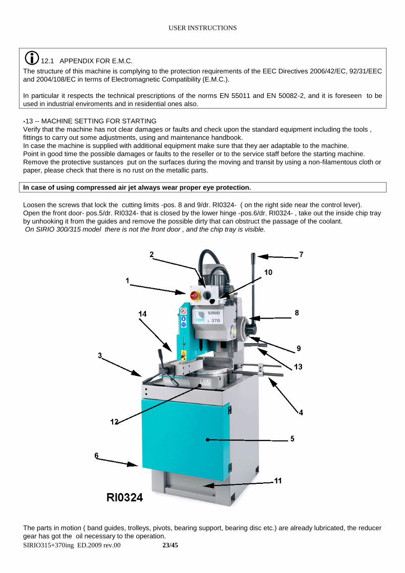
-13 -- MACHINE SETTING FOR STARTING
Verify that the machine has not clear damages or faults and check upon the standard equipment including the tools ,
fittings to carry out some adjustments, using and maintenance handbook.
In case the machine is supplied with additional equipment make sure that they aer adaptable to the machine.
Point in good time the possible damages or faults to the reseller or to the service staff before the starting machine.
Remove the protective sustances put on the surfaces during the moving and transit by using a non-filamentous cloth or
paper, please check that there is no rust on the metallic parts.
In case of using compressed air jet always wear proper eye protection.
Loosen the screws that lock the cutting limits -pos. 8 and 9/dr. RI0324- ( on the right side near the control lever).
Open the front door- pos.5/dr. RI0324- that is closed by the lower hinge -pos.6/dr. RI0324- , take out the inside chip tray
by unhooking it from the guides and remove the possible dirty that can obstruct the passage of the coolant.
On SIRIO 300/315 model there is not the front door , and the chip tray is visible.
The parts in motion ( band guides, trolleys, pivots, bearing support, bearing disc etc.) are already lubricated, the reducer
gear has got the oil necessary to the operation.
USER INSTRUCTIONS
SIRIO315+370ing ED.2009 rev.00 24/45
The possible pneumatic installation (ex. for the vice ) is ready to start; anywhere check if it is made by the indication of
INSTALLATION paragraph.
13.1 - COOLING AND LUBRICATION PLANT
Prepare the cooling by mixing the cutting oil and water ( the tank holds about 15 litres ) in proportion of 1/10, 1/15 or
according to the instructions of the supplier of the product.Pour the coolant into the tank placed inside the base; is
possible to reach it by front side after taking out lower part -pos.11/dr.RI0324 or by the back side.
If not you can pour it directly between the work table and the base - see 12/dr. RI0324-
. In this case keep attention that the removable chip tray and the tank are correctly placed.
- 13.2 - PNEUMATIC CONNECTION ( if required )
It is necessary to connect the machine to an installation equipped at least with a condensate discharger, filter and
reducer gear to make the pressure stable at 6/8 BAR about. It is possible to mount a pressure reducer gear for the
vice only in the case you cut material capable of being deformed.
13.3 -- ELECTRICAL CONNECTION
Verify that the voltage and the power frequency are compatible with numbers reported in the technical data plate ( It is
placed on the right side of the head column) a difference over 10% causes some working unevenness more or less
manifested.
Connect the switch to a suitable socket or replace it with that of normal use( in the case the switch must be
replaced , the work must be done by an electrician ). The phasing performed by the manufacturer allows to get
a rotation of all motors by connecting the wires in the following order L1=R, L2=S, L3=T, anyhow check as
follows : ( with compressed air connected, pressure not lower than 2 BAR ).
a) turnl the motor speed selector at 1- pos.2/dr.RI0324-.
b) close the cock of the coolant circuit-pos28/dr.RI0327-.
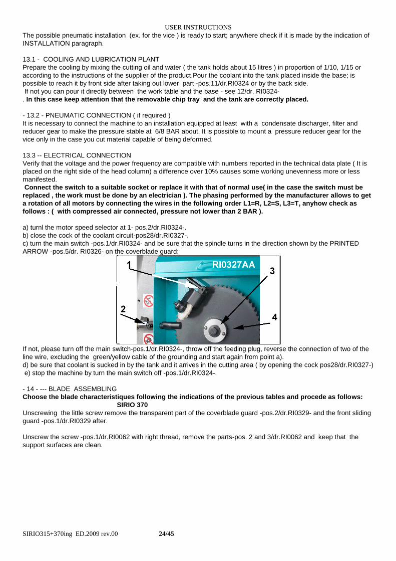
c) turn the main switch -pos.1/dr.RI0324- and be sure that the spindle turns in the direction shown by the PRINTED
ARROW -pos.5/dr. RI0326- on the coverblade guard;
If not, please turn off the main switch-pos.1/dr.RI0324-, throw off the feeding plug, reverse the connection of two of the
line wire, excluding the green/yellow cable of the grounding and start again from point a).
d) be sure that coolant is sucked in by the tank and it arrives in the cutting area ( by opening the cock pos28/dr.RI0327-)
e) stop the machine by turn the main switch off -pos.1/dr.RI0324-.
- 14 - --- BLADE ASSEMBLING
Choose the blade characteristiques following the indications of the previous tables and procede as follows:
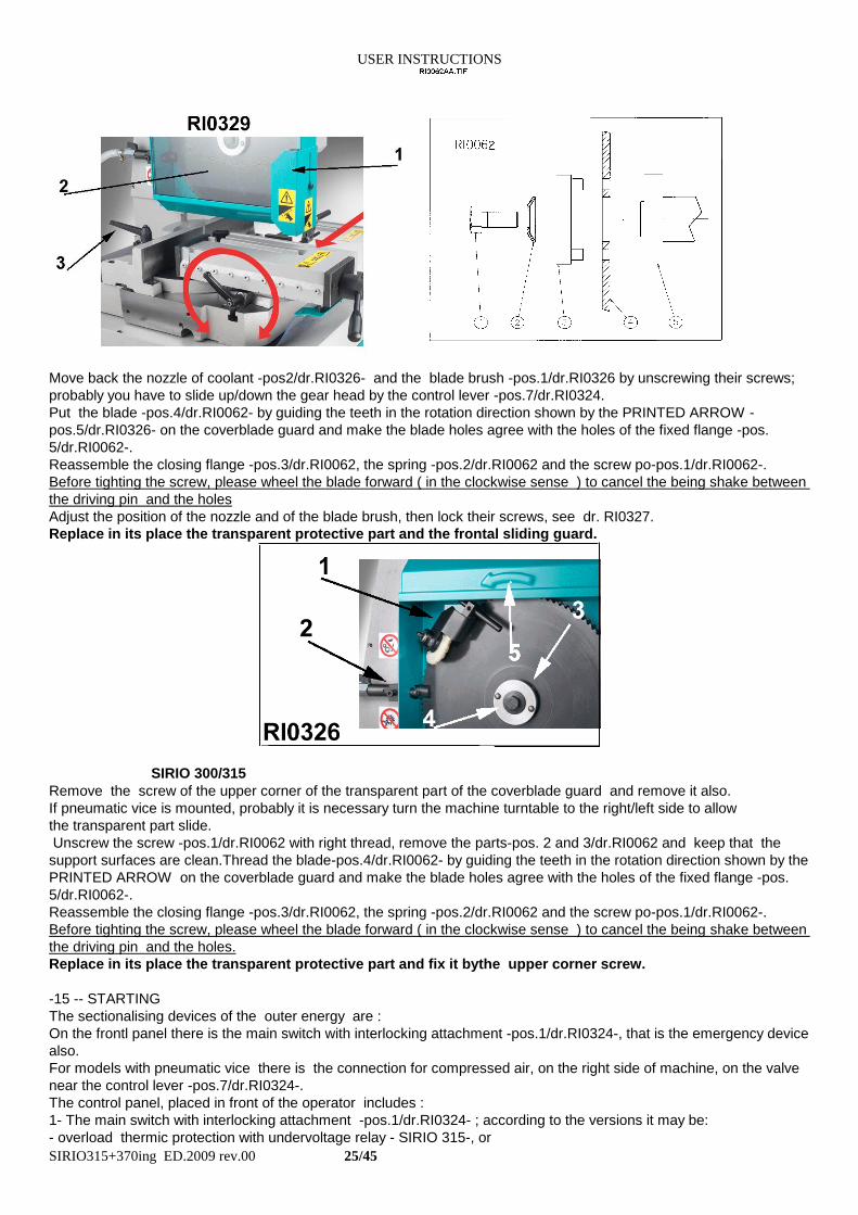
SIRIO 370
Unscrewing the little screw remove the transparent part of the coverblade guard -pos.2/dr.RI0329- and the front sliding
guard -pos.1/dr.RI0329 after.
Unscrew the screw -pos.1/dr.RI0062 with right thread, remove the parts-pos. 2 and 3/dr.RI0062 and keep that the
support surfaces are clean.
USER INSTRUCTIONS
SIRIO315+370ing ED.2009 rev.00 25/45
Move back the nozzle of coolant -pos2/dr.RI0326- and the blade brush -pos.1/dr.RI0326 by unscrewing their screws;
probably you have to slide up/down the gear head by the control lever -pos.7/dr.RI0324.
Put the blade -pos.4/dr.RI0062- by guiding the teeth in the rotation direction shown by the PRINTED ARROW -
pos.5/dr.RI0326- on the coverblade guard and make the blade holes agree with the holes of the fixed flange -pos.
5/dr.RI0062-.
Reassemble the closing flange -pos.3/dr.RI0062, the spring -pos.2/dr.RI0062 and the screw po-pos.1/dr.RI0062-.
Before tighting the screw, please wheel the blade forward ( in the clockwise sense ) to cancel the being shake between
the driving pin and the holes
Adjust the position of the nozzle and of the blade brush, then lock their screws, see dr. RI0327.
Replace in its place the transparent protective part and the frontal sliding guard.
SIRIO 300/315
Remove the screw of the upper corner of the transparent part of the coverblade guard and remove it also.
If pneumatic vice is mounted, probably it is necessary turn the machine turntable to the right/left side to allow
the transparent part slide.
Unscrew the screw -pos.1/dr.RI0062 with right thread, remove the parts-pos. 2 and 3/dr.RI0062 and keep that the
support surfaces are clean.Thread the blade-pos.4/dr.RI0062- by guiding the teeth in the rotation direction shown by the
PRINTED ARROW on the coverblade guard and make the blade holes agree with the holes of the fixed flange -pos.
5/dr.RI0062-.
Reassemble the closing flange -pos.3/dr.RI0062, the spring -pos.2/dr.RI0062 and the screw po-pos.1/dr.RI0062-.
Before tighting the screw, please wheel the blade forward ( in the clockwise sense ) to cancel the being shake between
the driving pin and the holes.
Replace in its place the transparent protective part and fix it bythe upper corner screw.
-15 -- STARTING
The sectionalising devices of the outer energy are :
On the frontl panel there is the main switch with interlocking attachment -pos.1/dr.RI0324-, that is the emergency device
also.
For models with pneumatic vice there is the connection for compressed air, on the right side of machine, on the valve
near the control lever -pos.7/dr.RI0324-.
The control panel, placed in front of the operator includes :
1- The main switch with interlocking attachment -pos.1/dr.RI0324- ; according to the versions it may be:
- overload thermic protection with undervoltage relay - SIRIO 315-, or
USER INSTRUCTIONS
SIRIO315+370ing ED.2009 rev.00 26/45
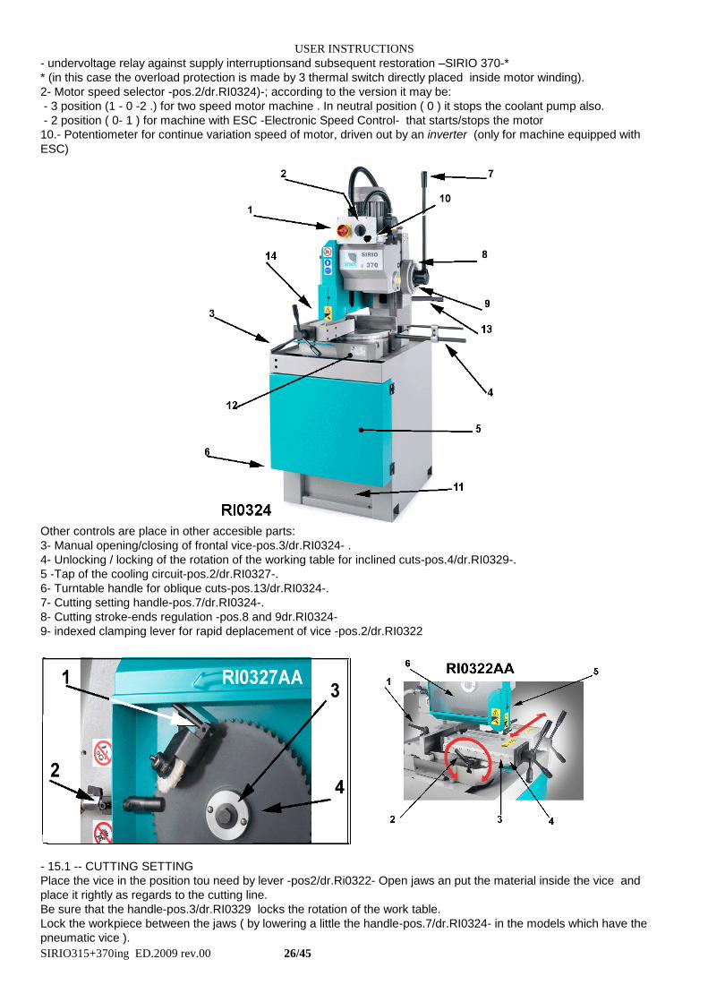
- undervoltage relay against supply interruptionsand subsequent restoration –SIRIO 370-*
* (in this case the overload protection is made by 3 thermal switch directly placed inside motor winding).
2- Motor speed selector -pos.2/dr.RI0324)-; according to the version it may be:
- 3 position (1 - 0 -2 .) for two speed motor machine . In neutral position ( 0 ) it stops the coolant pump also.
- 2 position ( 0- 1 ) for machine with ESC -Electronic Speed Control- that starts/stops the motor
10.- Potentiometer for continue variation speed of motor, driven out by an inverter (only for machine equipped with
ESC)
Other controls are place in other accesible parts:
3- Manual opening/closing of frontal vice-pos.3/dr.RI0324- .
4- Unlocking / locking of the rotation of the working table for inclined cuts-pos.4/dr.RI0329-.
5 -Tap of the cooling circuit-pos.2/dr.RI0327-.
6- Turntable handle for oblique cuts-pos.13/dr.RI0324-.
7- Cutting setting handle-pos.7/dr.RI0324-.
8- Cutting stroke-ends regulation -pos.8 and 9dr.RI0324-
9- indexed clamping lever for rapid deplacement of vice -pos.2/dr.RI0322
- 15.1 -- CUTTING SETTING
Place the vice in the position tou need by lever -pos2/dr.Ri0322- Open jaws an put the material inside the vice and
place it rightly as regards to the cutting line.
Be sure that the handle-pos.3/dr.RI0329 locks the rotation of the work table.
Lock the workpiece between the jaws ( by lowering a little the handle-pos.7/dr.RI0324- in the models which have the
pneumatic vice ).
USER INSTRUCTIONS
SIRIO315+370ing ED.2009 rev.00 27/45
Select the cutting speed with the control -pos.2/dr.RI0324-, close the cooling cock and turn on the the main switch-
pos1/dr.RI0324- Never change the speed during cutting work and wait until the blade do not turn.
(for ESC machine you can adjust blade speed during cutting operation also, remember use a slowly change by
using the knob 10/RI0324-).
Adjust the coolant flow and start the cutting by lowering handle; by this machine cutting efforts are very light because
the handle has a special device that reduce effectivecut stroke.If this handle-pos.7/dr.RI0324 is in inconvenient
position, please pull it on the outside to unhook it from the joint and wheel the handle until your choseen
position. Put the handle into the joint again to lift up or to lower the gear head.
We advise you to lower the coverblade guard so that it covers the blade much more. Loosen the 2 screws placed on
its side and place the coverblade guard down/up.
Don’t forget: : place the coverblade guard to the possible upper position when you change the cutting limits.
It is better to adjust the lenght also of the stroke that must be made for the cutting :
loosen the two screws -pos.8 and 9/dr.RI0324- that serves as mechanical stop and move them along the little round
cavity, depending on the needs.
15.2 - - STOP DEVICE / EMERGENCY STOP
In every moment it is possible to stop the cycle:
- by the main switch -pos.1/dr.RI0324- the machine stops immediately.
In case of electric energy interruption the sectionalising switch -pos.1/dr.RI0324- switches-off ( at 0 position) and it is
necessary to restore it for use the machine again.
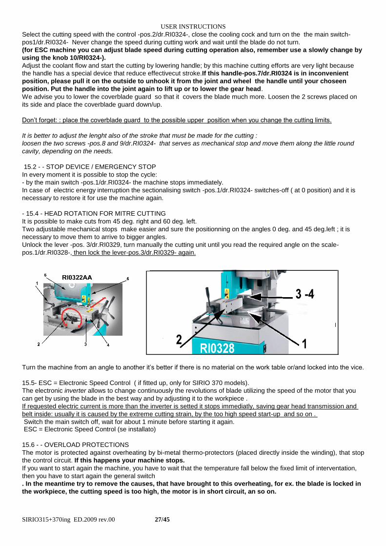
- 15.4 - HEAD ROTATION FOR MITRE CUTTING
It is possible to make cuts from 45 deg. right and 60 deg. left.
Two adjustable mechanical stops make easier and sure the positionning on the angles 0 deg. and 45 deg.left ; it is
necessary to move them to arrive to bigger angles.
Unlock the lever -pos. 3/dr.RI0329, turn manually the cutting unit until you read the required angle on the scale-
pos.1/dr.RI0328-, then lock the lever-pos.3/dr.RI0329- again.
Turn the machine from an angle to another it’s better if there is no material on the work table or/and locked into the vice.
15.5- ESC = Electronic Speed Control ( if fitted up, only for SIRIO 370 models).
The electronic inverter allows to change continuously the revolutions of blade utilizing the speed of the motor that you
can get by using the blade in the best way and by adjusting it to the workpiece .
If requested electric current is more than the inverter is setted it stops immediatly, saving gear head transmission and
belt inside: usually it is caused by the extreme cutting strain, by the too high speed start-up and so on .
Switch the main switch off, wait for about 1 minute before starting it again. ESC = Electronic Speed Control (se installato)
15.6 - - OVERLOAD PROTECTIONS
The motor is protected against overheating by bi-metal thermo-protectors (placed directly inside the winding), that stop
the control circuit. If this happens your machine stops.
If you want to start again the machine, you have to wait that the temperature fall below the fixed limit of interventation,
then you have to start again the general switch
. In the meantime try to remove the causes, that have brought to this overheating, for ex. the blade is locked in
the workpiece, the cutting speed is too high, the motor is in short circuit, an so on.
USER INSTRUCTIONS
SIRIO315+370ing ED.2009 rev.00 28/45
16 - - ADJUSTMENTS FOR SIRIO 370 and SIRIO 315 (disconnect machine from electrical supply )
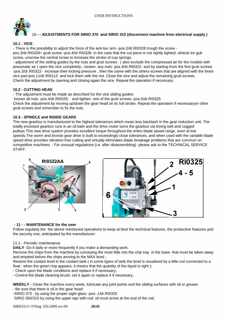
10.1 - VICE
- There is the possibility to adjust the force of the anti-bur arm -pos.2/dr.RI0328 trough the screw -
pos.3/dr.RI0328+ grub screw -pos.4/dr.RI0328- in the case that the cut piece is not rightly tighted: ulnlock tre gub
screw, unscrew the central screw to increase the stroke of cup springs.
- adjustment of the sliding guides by the nuts and grub screws : ( also exclude the compressed air for the models with
pneumatic air ) open the vice completely-, loosen any nuts- pos.4/dr.RI0322- and by starting from the first grub screws
-pos.3/dr.RI0322- increase their locking pressure , then the same with the others-screws that are aligned with the fixed-
vice part-pos.11/dr.RI0113 and lock them with the nut. Close the vice and adjust the remaining grub-screws.
Check the adjustment by opening and closing again the vice. Repeat the operation if necessary.
10.2 - CUTTING HEAD
- The adjustment must be made as described for the vice sliding guides:
loosen all nuts -pos.4/dr.RI0325- and tighten one of the grub screws -pos.5/dr.RI0325
Check the adjustment by moving up/down the gear head on its full stroke. Repeat the operation if necessaryon other
grub screws and remember to fix the nuts.
10.3 - SPINDLE and INSIDE GEARS
The new gearbox is manufactured to the highest tolerances which mean less backlash in the gear reduction unit. The
totally enclosed gearbox runs in an oil bath and the drive motor turns the gearbox via timing belt and cogged
pulleys.This new drive system provides excellent torque throughout the entire blade speed range, even at low
speeds.The worm and bronze gear drive is built to exceedingly close tolerances, and when used with the variable blade
speed drive provides vibration-free cutting and virtually eliminates blade breakage problems that are common on
competitive machines. - For unusual regulations (i.e. after disassembling) please ask to the TECHNICAL SERVICE
STAFF.
- 11 - - MAINTENANCE for the user
Follow regularly the the above mentioned operations to keep at best the technical features, the productive features and
the security one, anticipated by the manufacturer.
11.1 - Periodic maintenance
DAILY -Do it daily or more frequently if you make a demanding work.
Remove the chips from the machine by conveying the most little into the chip tray in the base- that must be taken away
and emptied before the chips arriving to the MAX level ;
Restore the coolant level in the coolant tank ( in some types of tank the level is visualized by a little rod connected to a
float : when the green ring appears, it means that the quantity of the liquid is right );
- Check upon the blade conditions and replace it if necessary;
- Control the blade cleaning brush, set it again or replace it if necessary..
WEEKLY - Clean the machine every week, lubricate any joint points and the sliding surfaces with oil or grease.
- Be sure that there is oil in the gear head:
-SIRIO 370 . by using the proper sight glass -pos-.1/dr.RI0325
SIRIO 300/315 by using the upper tap/ with rod: oil must arrive at the end of the rod.
USER INSTRUCTIONS
SIRIO315+370ing ED.2009 rev.00 29/45
MONTLY - Every month replace the coolant and clean the tank placed in the floor stand.
Clean perfectly the slides-pos.6/dr.RI0325- of the cutting unit and lubricate them again.
Be sure that any screws and nuts are well locked (if they can be loosened when using)
Check that stroke end and switches are working and the conditions of the cables, tubes and hydraulic-pneumatic
connections are good. Test all devices that are not usually very used.
YEARLY- or every 2000 hours of work - replace the oil of the reducer head gear by doing as recommended in the
paragraph MACHINE RUNNING-IN .
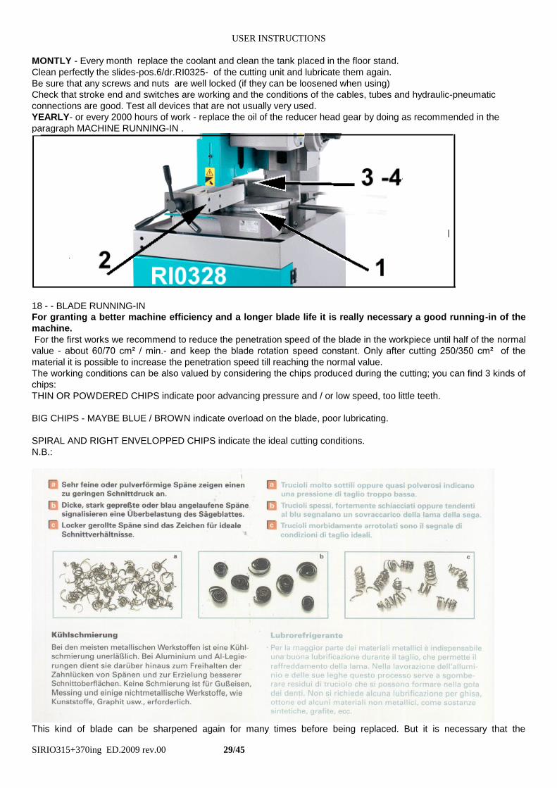
18 - - BLADE RUNNING-IN
For granting a better machine efficiency and a longer blade life it is really necessary a good running-in of the
machine.
For the first works we recommend to reduce the penetration speed of the blade in the workpiece until half of the normal
value - about 60/70 cm² / min.- and keep the blade rotation speed constant. Only after cutting 250/350 cm² of the
material it is possible to increase the penetration speed till reaching the normal value.
The working conditions can be also valued by considering the chips produced during the cutting; you can find 3 kinds of
chips:
THIN OR POWDERED CHIPS indicate poor advancing pressure and / or low speed, too little teeth.
BIG CHIPS - MAYBE BLUE / BROWN indicate overload on the blade, poor lubricating.
SPIRAL AND RIGHT ENVELOPPED CHIPS indicate the ideal cutting conditions.
N.B.:
This kind of blade can be sharpened again for many times before being replaced. But it is necessary that the
USER INSTRUCTIONS
SIRIO315+370ing ED.2009 rev.00 30/45
sharpening operation is made by keeping the initial features not to limit the using conditions or to cause the bad working
of the machine. The sharping process always causes a reduction of the original diameter and a variation of the teeth
form, that cannot be accepted over some values.
For a right use see the paragraph CHOICE OF THE BLADE
19- - MACHINE RUNNING-IN
The recurrent maintenance that this machine needs is necessary to guarantee the continuous right working in
the time and to keep the starting features of the machine.
At the beginning of the use you must do some extra operations to allow the all parts of the machine to settle down in
the final using conditions.
Please check frequently the working of the machine and do not overload it with too much cuts or to lock the blade in
the material.
For a time of 80/100 working hours control the oil level of the reducer head -by the sight glass -pos1/dr.RI325-
for SIRIO 300/315 model by taking the dipstick off (while the motor is stop ), the oil must lap the end of the stick ).
After this hours take out the oil ( better if it is warm )from the lower tap -pos.3/dr.RI0325- and drip it completely:
to be sure of this take out theupper tap -pos.3/dr.RI0325- (or the dipstick on SIRIO 300/315 models)
Put the tap again in its place and put into some gasoil to clean it inside .
Idle the motor for some seconds, take away this cleaning liquid and put into the new oil until the usual level is
restored. (2 lit for SIRIO 370 and 3.5 lit for SIRIO 300/315 about)
The presence of bronze or ferrous particles in the replaced oil is normal. The heating of the mechanical parts ( and the
oleodynamic parts for semautomatic/ automatic machines ) is part of the usual working and anyhow does not exceed
the foreseen thermic limits
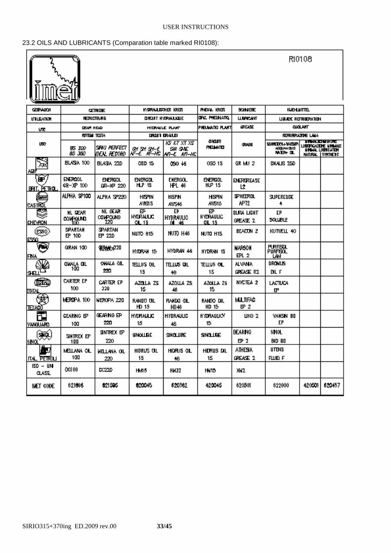
Please see the OIL AND LUBRICANTS TABLE (RI0108) to choose the most suitable one and to compare the
different types
- 20 - DRAINING OF USED / PRODUCED SUBSTANCES
Please remember to abide by the current Law Norms concerning the draining of:
- materials used by the machine (for example hydraulic circuit oil, reduction gear oil, oil for installations of lubrication
and so on);
- scrap materials or materials not usable anymore (for example ferrous and not ferrous chips, tools like blades and so
on);
- substances used for cleaning and maintenance;
- materials used in some instances of the machine life (for example when packing, shipping and so on).
21 -DEFECTS IDENTIFICATION
The solution of most part of the inconvenients that could happen during the work can be found by consulting this
paragraph.
The first part concerns the machine working and includes a list of the possible defects with respective controls that must
be made; the second part concerns the inconvenients that can be found by checking the blade and / or the cut pieces.
If your problem is not included in in the forseen ones or you need the presence of qualified technicians, please get in
touch with the manufacturer or the reseller by keeping this instruction book .
12.1 - DEFECTS CAUSED BY THE MACHINE
Inconvenients Check
A* Electric motor does not work (because of the blade) 1-3-4-13-14-15
B* The blade spindle works backwards 1-2
USER INSTRUCTIONS
SIRIO315+370ing ED.2009 rev.00 31/45
C* The blade does not work 15
D* The motor stops during the working 3-9-13-15-19-20
E* The blade stops easly during the cutting process 16-17-18-19-20
F* The coolant is not sufficient 5-6-7-8
G* The motor heating is high 13-14-15-19-20
H* The reducer heating is high 11-12-15-19-20
I* The blade locks in the workpiece during the cutting 10-16-18-23-24-25
L* The cut is not perpendicular to the worktable 10-11-17-18-20-22-23-25
M* The blade does not work right 11-22-26
N* The workpiece moves or deformes 20-23-24-25
O* The chip is thin or powdered 17-18-19-21
P* The chip is large or burnt 16-17-20
Q* The head does not get down till the cut end 26 27-28
R* There is too much burr on the cut piece 16-17-18-20-29-30
S* The electronical/electric panel does not light on 14-31-36-37-32
T* The head doesn’t go down regularly (autom.cut.models 10-27-33
U* The Automatic Cycle don’t start 34
LIST OF THE PARTS THAT MUST BE CONTROLLED
1 = Plug is right inserted in the socket
2 = The emergency button is pushed
3 = The line fuse (if there is)
4 = Main switch
5 = Tap of the coolant
6 = Chip tray tank too full
7 = Electropump of the coolant
8 = The tank is empty or dirty
9 = Excessive heating that determins the interventation of the thermoprotectors
10 = Excessive gap of the head guides
11 = Reducer bearings demaged or to be regulated
12 = Level of the head oil
13 = Burnt or demaged motor
14 = Electric feeding is not right
15 = Transmission blocked between blade and blade spindle. Damaged or worn out belt
16 = Teeth pitch of the blade
17 = Teeth form of the blade
18 = Used blade or missing teeth
19 = Cutting speed not right
20 = Excessive cutting pressure
21 = Unsufficient cutting pressure
22 = The flanges of the blade are dirty or wrong mounted
23 = The vice is not rightly closed, the workpiece is nor well blocked
24 = Rotation blocking lever for mitre cuts is not blocked
25 = The workpiece is not placed in the right way
26 = The safety screw for head downstroke (normally positioned for a dia 370 mm blade)
27 = The blade’s carter is not positioned in the right way
28 = The mechanical stroke ends of the head are not correctly positioned
29 = Jaw of the anti-bur device not correctly positioned
30 = Vice guides must be registered
31 = Fuses on the primary transformer circuit ( if there is)
32 = The compressed air has not been put inside (automatic cut.models )
33 = There is no oil in the hydraulic circuit (automatic cut models )
34 = The electric stroke ends of the feeder are not correctly posisitoned (full automatic models)
35 = Back selector rotated on SBLOCCO / INVERSIONE (automatic cut models)
36 = Fuses are on the secondary transformer circuit (if there is)
37 = Transformer demaged or burnt (if there is)
12.2 - DEFECTS OF THE BLADE / CAUSES / SOLUTIONS
In case of broken teeth, broken blades or short blade life, please check the defects; look for them in the following list
and read the solution of the cutting problem .
USER INSTRUCTIONS
SIRIO315+370ing ED.2009 rev.00 32/45
1. PREMATURE AND EXCESSIVE TEETH WEAR AND TEAR
- insufficient pressure - the teeth slide on the material
- cutting speed to high - the teeth slide on the material
- cooling jet too short;
- improper cooling emulsion;
- toothing too big or overloaded;
- running-in of the blade not appropriate;
- the blade has been mounted contrarily: turn the blade.
2. THE TEETH BREAK / THE BLADE BREAKS
- the teeth are too big for the section that must be cut; they are overloaded, at least 3 teeth should work at the
same time
- the teeth are too thin for the section that must be cut; exhaust throats are full of chips
- the material is not perfectly blocked;
- cutting pressure is too high, possible locking in the material
- the blade is not well fixed to the spindle
- the cut has beeb started against one angle
- high pressure: the teeth are overloaded and lock in the workpiece
3. BENT CUTS
- pressure is too high
- the speed is too high
- the blade must be sharpened
22 - MACHINE DEMOLITION
This paragraph may give some informations about the macrooperations of machine disassembly for its scrapping.
Special procedures are not required but it is necessary to take only some cares to avoid damages in the last phase of
the machine life.
Generally: you must empty the cooling installation tank, take out the oil from the reduction box, from the hydraulic or
hydropneumatic installation.
Lock the parts that could move and cause danger or instability.
Remove the parts assigned to the differentiated draining, for example the printed circuit, display stations,
programming keyboards, buffer batteries and so on, especially the ones which shows the picture ..In these
cases, in relation with the WEEE/AEEE Regulations, ask to the supplier to know the right process, that depends by the
machine size and purpose
-23 - SPARE PARTS The choice of the required spare parts is aided by the included drawings that allow, together with the hydraulic and electric working schemes, to know better the machine 23.1- NORMS TO REQUEST THE SPARE PARTS
It is necessary to inform the TECHNICAL SERVICE about the following data:
- the serial number indicated on the identification plate
- model, version, type
- voltage and power frequency
- code number of the spare-parts
- requested quality
- eventually the fittings settled later too.
USER INSTRUCTIONS
SIRIO315+370ing ED.2009 rev.00 33/45
23.2 OILS AND LUBRICANTS (Comparation table marked RI0108):
USER INSTRUCTIONS
SIRIO315+370ing ED.2009 rev.00 34/45
24 - MAINTENANCE - for qualified technicians
---------------------------------------------------------------------------------------------------------------------------------------------
IMPORTANT
-----------------------------------------------------------------------------------------------------------------------------------------------
If you want to make some special maintenance/disassembly/resetting operations on the machine, it is necessary to
know all information for working in safe conditions.
And then the knowledge of the interventation techniques, proper of the qualified technicians, allow to solve easier all
problems found by the user during the machine’s life. This allows to re-establish better the technical, productive and
safety features, forseen by the manufacturer.
For giving a detailed knowledge of this model you can find here enclosed as follows:
- Electrical scheme/s: divided into theme tables and made according to the current norms concerning this subject, with
index, material indication, reference code numbers.
- Pneumatic and hydro-pneumatic circuit
- Spare parts drawings: divided into tables about the main subsets making the machine. They indicate the code
numbers, the description and the quantity required too. For electric/pneumatic components, pls. Refers to the enclosed
circuits
If the user wants to know his machine in details, he can study this manual and use it carefully, but he has not to make
direct interventations for modifying or elaborating the machine, because in this way he would make the DECLARATION
OF CONFORMIITY invalid.
USER INSTRUCTIONS
SIRIO315+370ing ED.2009 rev.00 35/45
USER INSTRUCTIONS
SIRIO315+370ing ED.2009 rev.00 36/45
xxxxxxxxxxxxxxxxxxxxxxxxxxx
USER INSTRUCTIONS
SIRIO315+370ing ED.2009 rev.00 37/45
xxxxxxxxxxxxxxxxxxxxxxxxxx
USER INSTRUCTIONS
SIRIO315+370ing ED.2009 rev.00 38/45
USER INSTRUCTIONS
SIRIO315+370ing ED.2009 rev.00 39/45

USER INSTRUCTIONS
SIRIO315+370ing ED.2009 rev.00 8/45
USER INSTRUCTIONS
SIRIO315+370ing ED.2009 rev.00 9/45

USER INSTRUCTIONS
SIRIO315+370ing ED.2009 rev.00 10/45
USER INSTRUCTIONS
SIRIO315+370ing ED.2009 rev.00 11/45
USER INSTRUCTIONS
SIRIO315+370ing ED.2009 rev.00 12/45
USER INSTRUCTIONS
SIRIO315+370ing ED.2009 rev.00 13/45
USER INSTRUCTIONS
SIRIO315+370ing ED.2009 rev.00 14/45
USER INSTRUCTIONS
SIRIO315+370ing ED.2009 rev.00 15/45

USER INSTRUCTIONS
SIRIO315+370ing ED.2009 rev.00 16/45

USER INSTRUCTIONS
SIRIO315+370ing ED.2009 rev.00 17/45

USER INSTRUCTIONS
SIRIO315+370ing ED.2009 rev.00 18/45
USER INSTRUCTIONS
SIRIO315+370ing ED.2009 rev.00 19/45