Embed Size (px)
Citation preview
High efficiency wall-mounted gas-fired boilers Instructions for the User and the Installer
GB
Nagy hatásfokú falra szerelhető gáztüzelésű kazánokFelszerelési és használati utasítás
HU
Centrale murale pe gaz cu randament ridicatInstrucţiuni pentru instalator i pentru utilizatorRO
2925.224.2 - GBInstrUctIons pertaInInG to tHe User
Dear Customer,We are sure your new boiler will comply with all your requirements.Purchasing one of the Westen products satisfies your ex pec ta tions: good functioning, simplicity and ease of use.Do not dispose of this booklet without reading it: you can find here some very useful information, which will help you to run your boiler correctly and efficiently.
Do not leave any parts of the packaging (plastic bags, polystyrene, etc.) within children’s reach as they are a potential source of danger.
1. Instructions prior to installation 32. Instructions prior to commissioning 33. Commissioning of the boiler 44. Central Heating (CH) and Domestic Hot Water (D.H.W.) temperature adjustment 55. Filling the boiler 66. Turning off the boiler 67. Gas change 68. Prolonged standstill of the system. Frost protection 69. Error messages and table of faults 710. Servicing instructions 7
11. General information 812. Instructions prior to installation 813. Boiler installation 914. Boiler size 915. Installation of flue and air ducts 1016. Connecting the mains supply 1417. Fitting a room thermostat 1518. Gas change modalities 1519. Information display 1720. Parameters setting 1921. Control and operation devices 2022. Positioning of the ignition and flame sensing electrode 2123. Check of combustion parameters 2124. Output / pump head performances 2125. Connection of the external probe 2226. Connecting an external hot water tank and 3-way valve motor 2327. Electrical connections to remote control device 2428. Electrical connections to a zonal heating system 2529. How to purge the DHW system from limestone deposits 2630. How to disassemble the DHW heat exchanger 2631. Cleaning the cold water filter 2632. Boiler schematic 2733. Illustrated wiring diagram 3034. Technical data 33
cOntents
istRUctiOns peRtaininG tO tHe UseR
istRUctiOns peRtaininG tO tHe installeR
Westen declares that these models of boiler bear the CE mark in compliance with the basic requirements of the following Directives: - Gas Directive 90/396/EEC- Efficiency Directive 92/42/EEC- Electromagnetic Compatibility Directive 2004/108/EEC- Low Voltage Directive 2006/95/EC
3925.224.2 - GBInstrUctIons pertaInInG to tHe User
This boiler is designed to heat water at a lower than boiling temperature at atmospheric pressure. The boiler must be connected to a central heating system and to a domestic hot water supply system in compliance with its performances and output power.Have the boiler installed by a Qualified Service Engineer and ensure the following operations are accomplished:
a) careful checking that the boiler is fit for operation with the type of gas available. For more details see the notice on the packaging and the label on the appliance itself.
b) careful checking that the flue terminal draft is appropriate; that the terminal is not obstructed and that no other appliance exhaust gases are expelled through the same flue duct, unless the flue is especially designed to collect the exhaust gas coming from more than one appliance, in conformity with the laws and regulations in force.
c) careful checking that, in case the flue has been connected to pre-existing flue ducts, thorough cleaning has been carried out in that residual combustion products may come off during operation of the boiler and obstruct the flue duct.
d) to ensure correct operation of the appliance and avoid invalidating the guarantee, observe the following precautions:
1. Hot water circuit:
1.1. If the water hardness is greater than 20 °F (1 °F = 10 mg calcium carbonate per litre of water) a polyphosphate or comparable treatment system responding to current regulations.
1.2. Domestic Hot Water circuit must be thoroughly flushed after the installation of the appliance and before its use.
1.3. The materials used for the domestic hot water circuit of the product comply with Directive 98/83/EC.
2. Heating circuit
2.1. new system Before proceeding with installation of the boiler, the system must be cleaned and flushed out thoroughly to eliminate
residual thread-cutting swarf, solder and solvents if any, using suitable proprietary products. To avoid damaging metal, plastic and rubber parts, use only neutral cleaners, i.e. non-acid and non alkaline. The recommended products for cleaning are: SENTINEL X300 or X400 and FERNOX heating circuit restore. To use this product proceeding strictly in accordance with the maker’s directions.
2.2. existing system Before proceeding with installation of the boiler, the system must be cleaned and flushed out to remove sludge and
contaminants, using suitable proprietary products as described in section 2.1. To avoid damaging metal, plastic and rubber parts, use only neutral cleaners, i.e. non-acid and non-alkaline such as SENTINEL X100 and FERNOX heating circuit protective. To use this product proceeding strictly in accordance with the maker’s directions. Remember that the presence of foreign matter in the heating system can adversely affect the operation of the boiler (e.g. overheating and noisy operation of the heat exchanger).
Failure to observe the above will render the guarantee null and void.
1. instRUctiOns pRiOR tO installatiOn
Initial lighting of the boiler must be carried out by a licensed technician. Ensure the following operations are carried out:a) compliance of boiler parameters with (electricity, water, gas) supply systems settings.b) compliance of installation with the laws and regulations in force.c) appropriate connection to the power supply and grounding of the appliance.
Failure to observe the above will render the guarantee null and void.Prior to commissioning remove the protective plastic coating from the unit. Do not use any tools or abrasive detergents as you may spoil the painted surfaces.
The instructions shall state the substance of the following:This appliance is not intended for use by persons (including children) with reduced physical, sensory or mental capabilities, or lack of experience and knowledge, unless they have been given supervision or instruction concer-ning use of the appliance by a person responsible for their safety.Children should be supervised to ensure that they do not play with the appliance.
2. instRUctiOns pRiOR tO cOmmissiOninG
4925.224.2 - GBInstrUctIons pertaInInG to tHe User
3. cOmmissiOninG Of tHe BOileR
Figure 1
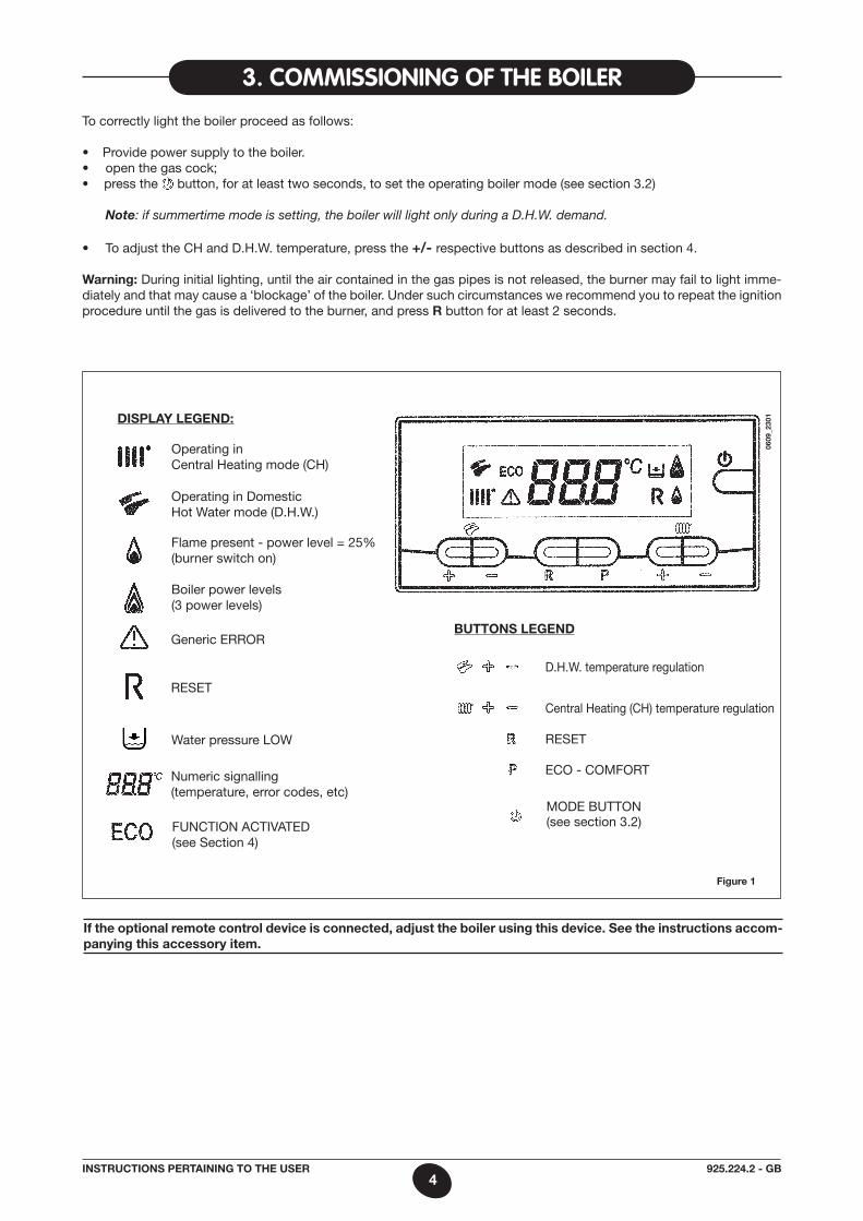
To correctly light the boiler proceed as follows:
• Providepowersupplytotheboiler.• openthegascock;• press the button, for at least two seconds, to set the operating boiler mode (see section 3.2)
Note: if summertime mode is setting, the boiler will light only during a D.H.W. demand.
• ToadjusttheCHandD.H.W.temperature,pressthe+/- respective buttons as described in section 4.
Warning: During initial lighting, until the air contained in the gas pipes is not released, the burner may fail to light imme-diately and that may cause a ‘blockage’ of the boiler. Under such circumstances we recommend you to repeat the ignition procedure until the gas is delivered to the burner, and press r button for at least 2 seconds.
dIsplay leGend:
Operating in Central Heating mode (CH)
Generic ERROR
Water pressure LOW
Numeric signalling(temperature, error codes, etc)
RESET
FUNCTION aCTIVaTED (see Section 4)
Flame present - power level = 25% (burner switch on)
Boiler power levels (3 power levels)
Operating in Domestic Hot Water mode (D.H.W.)
BUttons leGend
D.H.W. temperature regulation
Central Heating (CH) temperature regulation
RESET
ECO - COmFORT06
09_2
301
mODE BUTTON (see section 3.2)
If the optional remote control device is connected, adjust the boiler using this device. see the instructions accom-panying this accessory item.
5925.224.2 - GBInstrUctIons pertaInInG to tHe User
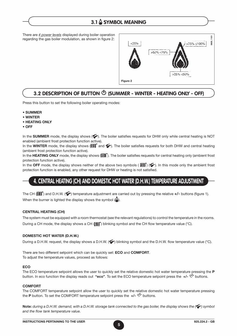
There are 4 power levels displayed during boiler operation regarding the gas boiler modulation, as shown in figure 2:
4. centRal HeatinG (cH) and dOmestic HOt WateR (d.H.W.) tempeRatURe adjUstment
The CH ( ) and D.H.W. ( ) temperature adjustment are carried out by pressing the relative +/- buttons (figure 1).
When the burner is lighted the display shows the symbol ( ).
central HeatInG (cH)
The system must be equipped with a room thermostat (see the relevant regulations) to control the temperature in the rooms.
During a CH mode, the display shows a CH ( ) blinking symbol and the CH flow temperature value (°C).
domestIc Hot Water (d.H.W.)
During a D.H.W. request, the display shows a D.H.W. ( ) blinking symbol and the D.H.W. flow temperature value (°C).
There are two different setpoint which can be quickly set: eco and comFort.To adjust the temperature values, proceed as follows: ecoThe ECO temperature setpoint allows the user to quickly set the relative domestic hot water temperature pressing the p button. In eco function the display reads out “eco”. To set the ECO temperature setpoint press the +/- buttons.
comFortThe COmFORT temperature setpoint allow the user to quickly set the relative domestic hot water temperature pressing the p button. To set the COmFORT temperature setpoint press the +/- buttons.
note: during a D.H.W. demand, with a D.H.W. storage tank connected to the gas boiler, the display shows the ( ) symbol and the flow tank temperature value.
3.1 symBOl meaninG
0605
_110
1
Figure 2
3.2 descRiptiOn Of BUttOn (sUmmeR - WinteR - HeatinG Only - Off)
Press this button to set the following boiler operating modes: • SUMMER• WINTER• HEATING ONLY• OFF
In the sUmmer mode, the display shows ( ). The boiler satisfies requests for DHW only while central heating is NOT enabled (ambient frost protection function active).In the WInter mode, the display shows ( and ). The boiler satisfies requests for both DHW and central heating (ambient frost protection function active).In the HeatInG only mode, the display shows ( ). The boiler satisfies requests for central heating only (ambient frost protection function active).In the oFF mode, the display shows neither of the above two symbols ( ) ( ). In this mode only the ambient frost protection function is enabled, any other request for DHW or heating is not satisfied.
6925.224.2 - GBInstrUctIons pertaInInG to tHe User
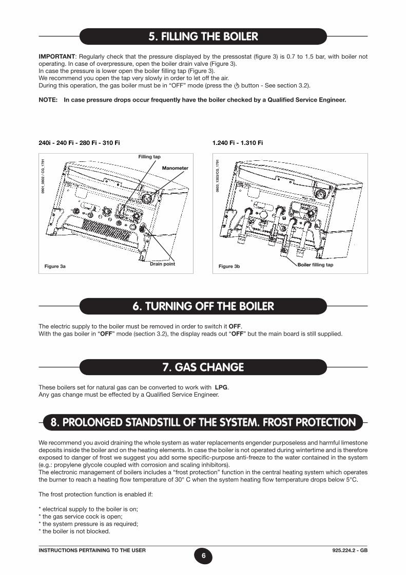
Important: Regularly check that the pressure displayed by the pressostat (figure 3) is 0.7 to 1.5 bar, with boiler not operating. In case of overpressure, open the boiler drain valve (Figure 3).In case the pressure is lower open the boiler filling tap (Figure 3).We recommend you open the tap very slowly in order to let off the air.During this operation, the gas boiler must be in “OFF” mode (press the button - See section 3.2).
note: In case pressure drops occur frequently have the boiler checked by a Qualified service engineer.
5. fillinG tHe BOileR
The electric supply to the boiler must be removed in order to switch it oFF. With the gas boiler in “oFF” mode (section 3.2), the display reads out “oFF” but the main board is still supplied.
6. tURninG Off tHe BOileR
7. Gas cHanGe
These boilers set for natural gas can be converted to work with lpG. any gas change must be effected by a Qualified Service Engineer.
We recommend you avoid draining the whole system as water replacements engender purposeless and harmful limestone deposits inside the boiler and on the heating elements. In case the boiler is not operated during wintertime and is therefore exposed to danger of frost we suggest you add some specific-purpose anti-freeze to the water contained in the system (e.g.: propylene glycole coupled with corrosion and scaling inhibitors).The electronic management of boilers includes a “frost protection” function in the central heating system which operates the burner to reach a heating flow temperature of 30° C when the system heating flow temperature drops below 5°C.
The frost protection function is enabled if:
* electrical supply to the boiler is on;* the gas service cock is open;* the system pressure is as required;* the boiler is not blocked.
8. pROlOnGed standstill Of tHe system. fROst pROtectiOn
Figure 3a
Filling tap
drain point
manometer
Figure 3b
0603
_130
3/c
G_1
791
240i - 240 Fi - 280 Fi - 310 Fi 1.240 Fi - 1.310 Fi
Boiler filling tap
0901
_080
2 /
cG
_179
1
7925.224.2 - GBInstrUctIons pertaInInG to tHe User
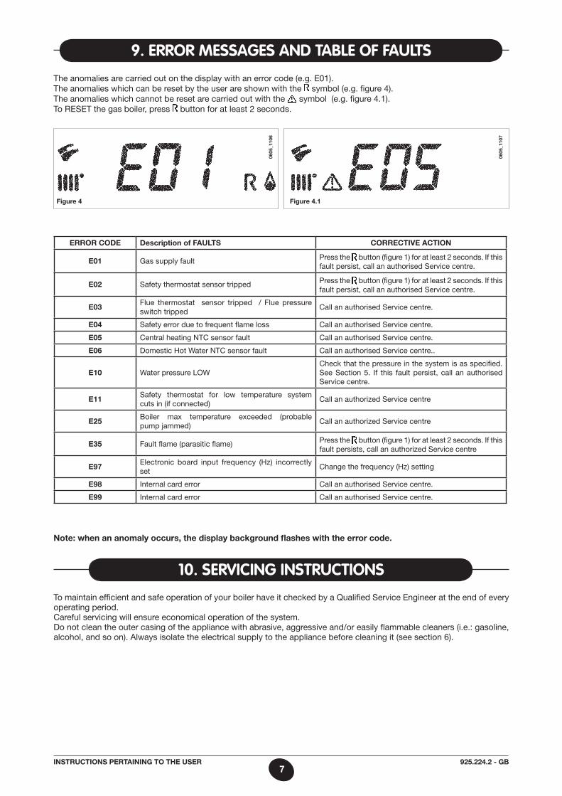
9. eRROR messaGes and taBle Of faUlts
To maintain efficient and safe operation of your boiler have it checked by a Qualified Service Engineer at the end of every operating period.Careful servicing will ensure economical operation of the system.Do not clean the outer casing of the appliance with abrasive, aggressive and/or easily flammable cleaners (i.e.: gasoline, alcohol, and so on). always isolate the electrical supply to the appliance before cleaning it (see section 6).
10. seRvicinG instRUctiOns
error code description of FaUlts correctIve actIon
e01 Gas supply fault Press the button (figure 1) for at least 2 seconds. If this fault persist, call an authorised Service centre.
e02 Safety thermostat sensor tripped Press the button (figure 1) for at least 2 seconds. If this fault persist, call an authorised Service centre.
e03Flue thermostat sensor tripped / Flue pressure switch tripped
Call an authorised Service centre.
e04 Safety error due to frequent flame loss Call an authorised Service centre.
e05 Central heating NTC sensor fault Call an authorised Service centre.
e06 Domestic Hot Water NTC sensor fault Call an authorised Service centre..
e10 Water pressure LOWCheck that the pressure in the system is as specified. See Section 5. If this fault persist, call an authorised Service centre.
e11Safety thermostat for low temperature system cuts in (if connected)
Call an authorized Service centre
e25Boiler max temperature exceeded (probable pump jammed)
Call an authorized Service centre
e35 Fault flame (parasitic flame) Press the button (figure 1) for at least 2 seconds. If this fault persists, call an authorized Service centre
e97Electronic board input frequency (Hz) incorrectly set
Change the frequency (Hz) setting
e98 Internal card error Call an authorised Service centre.
e99 Internal card error Call an authorised Service centre.
Figure 4
0605
_110
6
note: when an anomaly occurs, the display background flashes with the error code.
The anomalies are carried out on the display with an error code (e.g. E01).The anomalies which can be reset by the user are shown with the symbol (e.g. figure 4).The anomalies which cannot be reset are carried out with the symbol (e.g. figure 4.1).To RESET the gas boiler, press button for at least 2 seconds.
Figure 4.1
0605
_110
7
8925.224.2 - GBInstrUctIons pertaInInG to tHe Installer
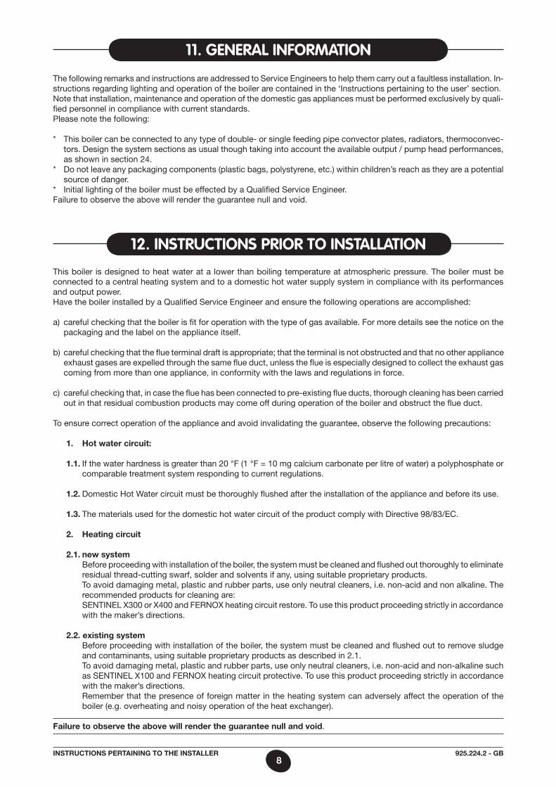
This boiler is designed to heat water at a lower than boiling temperature at atmospheric pressure. The boiler must be connected to a central heating system and to a domestic hot water supply system in compliance with its performances and output power.Have the boiler installed by a Qualified Service Engineer and ensure the following operations are accomplished:
a) careful checking that the boiler is fit for operation with the type of gas available. For more details see the notice on the packaging and the label on the appliance itself.
b) careful checking that the flue terminal draft is appropriate; that the terminal is not obstructed and that no other appliance exhaust gases are expelled through the same flue duct, unless the flue is especially designed to collect the exhaust gas coming from more than one appliance, in conformity with the laws and regulations in force.
c) careful checking that, in case the flue has been connected to pre-existing flue ducts, thorough cleaning has been carried out in that residual combustion products may come off during operation of the boiler and obstruct the flue duct.
To ensure correct operation of the appliance and avoid invalidating the guarantee, observe the following precautions:
1. Hot water circuit:
1.1. If the water hardness is greater than 20 °F (1 °F = 10 mg calcium carbonate per litre of water) a polyphosphate or comparable treatment system responding to current regulations.
1.2. Domestic Hot Water circuit must be thoroughly flushed after the installation of the appliance and before its use.
1.3. The materials used for the domestic hot water circuit of the product comply with Directive 98/83/EC.
2. Heating circuit
2.1. new system Before proceeding with installation of the boiler, the system must be cleaned and flushed out thoroughly to eliminate
residual thread-cutting swarf, solder and solvents if any, using suitable proprietary products. To avoid damaging metal, plastic and rubber parts, use only neutral cleaners, i.e. non-acid and non alkaline. The
recommended products for cleaning are: SENTINEL X300 or X400 and FERNOX heating circuit restore. To use this product proceeding strictly in accordance
with the maker’s directions.
2.2. existing system Before proceeding with installation of the boiler, the system must be cleaned and flushed out to remove sludge
and contaminants, using suitable proprietary products as described in 2.1. To avoid damaging metal, plastic and rubber parts, use only neutral cleaners, i.e. non-acid and non-alkaline such
as SENTINEL X100 and FERNOX heating circuit protective. To use this product proceeding strictly in accordance with the maker’s directions.
Remember that the presence of foreign matter in the heating system can adversely affect the operation of the boiler (e.g. overheating and noisy operation of the heat exchanger).
Failure to observe the above will render the guarantee null and void.
The following remarks and instructions are addressed to Service Engineers to help them carry out a faultless installation. In-structions regarding lighting and operation of the boiler are contained in the ‘Instructions pertaining to the user’ section.Note that installation, maintenance and operation of the domestic gas appliances must be performed exclusively by quali-fied personnel in compliance with current standards.Please note the following:
* This boiler can be connected to any type of double- or single feeding pipe convector plates, radiators, thermoconvec-tors. Design the system sections as usual though taking into account the available output / pump head performances, as shown in section 24.
* Do not leave any packaging components (plastic bags, polystyrene, etc.) within children’s reach as they are a potential source of danger.
* Initial lighting of the boiler must be effected by a Qualified Service Engineer. Failure to observe the above will render the guarantee null and void.
11. GeneRal infORmatiOn
12. instRUctiOns pRiOR tO installatiOn
9925.224.2 - GBInstrUctIons pertaInInG to tHe Installer
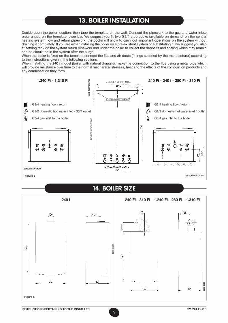
13. BOileR installatiOn
Decide upon the boiler location, then tape the template on the wall. Connect the pipework to the gas and water inlets prearranged on the template lower bar. We suggest you fit two G3/4 stop cocks (available on demand) on the central heating system flow and return pipework; the cocks will allow to carry out important operations on the system without draining it completely. If you are either installing the boiler on a pre-existent system or substituting it, we suggest you also fit settling tank on the system return pipework and under the boiler to collect the deposits and scaling which may remain and be circulated in the system after the purge.When the boiler is fixed on the template connect the flue and air ducts (fittings supplied by the manufacturer) according to the instructions given in the following sections.When installing the 240 i model (boiler with natural draught), make the connection to the flue using a metal pipe which will provide resistance over time to the normal mechanical stresses, heat and the effects of the combustion products and any condensation they form.
14. BOileR size
Figure 6
240 i 240 Fi - 310 Fi - 1.240 Fi - 280 Fi - 1.310 Fi
min
imo
0606
_260
2
0606
_260
3
Figure 5
= BOILER WIDTH 450 =
BOILER CONNECTION POINTS
BO
ILE
R H
EIG
HT
780
: G3/4 heating flow / return
: G1/2 domestic hot water inlet / outlet
: G3/4 gas inlet to the boiler
0512
_050
4/c
G17
69
0512_0505/cG1769
0512_0503/cG1769
: G3/4 heating flow / return
: G1/2 domestic hot water inlet - G3/4 outlet
: G3/4 gas inlet to the boiler
240 Fi - 240 i - 280 Fi - 310 Fi 1.240 Fi - 1.310 Fi
10925.224.2 - GBInstrUctIons pertaInInG to tHe Installer
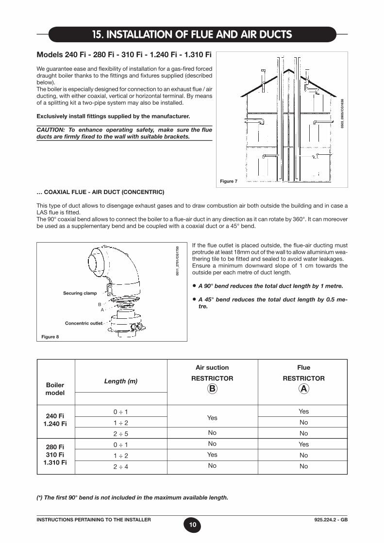
15. installatiOn Of flUe and aiR dUcts
models 240 Fi - 280 Fi - 310 Fi - 1.240 Fi - 1.310 Fi
We guarantee ease and flexibility of instal lation for a gas-fired forced draught boiler thanks to the fittings and fixtures supplied (described below).The boiler is especially designed for connection to an exhaust flue / air ducting, with either coaxial, vertical or horizontal terminal. By means of a splitting kit a two-pipe system may also be installed.
exclusively install fittings supplied by the manufacturer.
CAUTION: To enhance operating safety, make sure the flue ducts are firmly fixed to the wall with suitable brackets.
Figure 7
0503
_090
5/c
G16
38Figure 8
… coaxIal FlUe - aIr dUct (concentrIc)
This type of duct allows to disengage exhaust gases and to draw combustion air both outside the building and in case a LaS flue is fitted.The 90° coaxial bend allows to connect the boiler to a flue-air duct in any direction as it can rotate by 360°. It can moreover be used as a supplementary bend and be coupled with a coaxial duct or a 45° bend.
0511
_270
1/c
G17
50
If the flue outlet is placed outside, the flue-air ducting must protrude at least 18mm out of the wall to allow alluminium wea-thering tile to be fitted and sealed to avoid water leakages.Ensure a minimum downward slope of 1 cm towards the outside per each metre of duct length.
• A 90° bend reduces the total duct length by 1 metre.
• A 45° bend reduces the total duct length by 0.5 me-tre.
securing clamp
concentric outlet
aB
(*) The first 90° bend is not included in the maximum available length.
Boiler model
240 Fi1.240 Fi
280 Fi310 Fi
1.310 Fi
0 ÷ 1
1 ÷ 2
2 ÷ 5
0 ÷ 1
1 ÷ 2
2 ÷ 4
Length (m)
air suction
restrIctor
B
Yes
No
No
Yes
No
Flue
restrIctor
a
Yes
No
No
Yes
No
No
11925.224.2 - GBInstrUctIons pertaInInG to tHe Installer
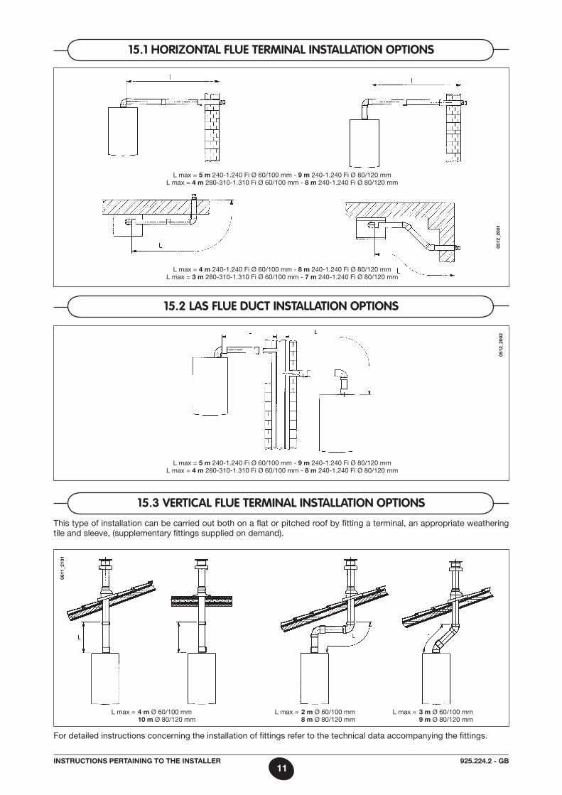
15.1 HORizOntal flUe teRminal installatiOn OptiOns
15.2 las flUe dUct installatiOn OptiOns
15.3 veRtical flUe teRminal installatiOn OptiOnsThis type of installation can be carried out both on a flat or pitched roof by fitting a terminal, an appropriate weathering tile and sleeve, (supplementary fittings supplied on demand).
0611
_210
1
0512
_200
105
12_2
002
For detailed instructions concerning the installation of fittings refer to the technical data accompanying the fittings.
L max = 5 m 240-1.240 Fi Ø 60/100 mm - 9 m 240-1.240 Fi Ø 80/120 mmL max = 4 m 280-310-1.310 Fi Ø 60/100 mm - 8 m 240-1.240 Fi Ø 80/120 mm
L max = 4 m 240-1.240 Fi Ø 60/100 mm - 8 m 240-1.240 Fi Ø 80/120 mmL max = 3 m 280-310-1.310 Fi Ø 60/100 mm - 7 m 240-1.240 Fi Ø 80/120 mm
L max = 5 m 240-1.240 Fi Ø 60/100 mm - 9 m 240-1.240 Fi Ø 80/120 mmL max = 4 m 280-310-1.310 Fi Ø 60/100 mm - 8 m 240-1.240 Fi Ø 80/120 mm
L max = 2 m Ø 60/100 mm 8 m Ø 80/120 mm
L max = 4 m Ø 60/100 mm 10 m Ø 80/120 mm
L max = 3 m Ø 60/100 mm 9 m Ø 80/120 mm
12925.224.2 - GBInstrUctIons pertaInInG to tHe Installer
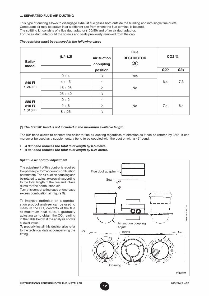
… separated FlUe-aIr dUctInG
This type of ducting allows to disengage exhaust flue gases both outside the building and into single flue ducts.Comburant air may be drawn in at a different site from where the flue terminal is located.The splitting kit consists of a flue duct adaptor (100/80) and of an air duct adaptor. For the air duct adaptor fit the screws and seals previously removed from the cap.
The restrictor must be removed in the following cases
Figure 9
The 90° bend allows to connect the boiler to flue-air ducting regardless of direction as it can be rotated by 360°. It can moreover be used as a supplementary bend to be coupled with the duct or with a 45° bend.
• A 90° bend reduces the total duct length by 0.5 metre.• A 45° bend reduces the total duct length by 0.25 metre.
0604
/230
1/c
G17
76
(*) The first 90° bend is not included in the maximum available length.
split flue air control adjustment
The adjustment of this control is required to optimise performance and combustion parameters. The air suction coupling can be rotated to adjust excess air according to the total length of the flue and intake ducts for the combustion air.Turn this control to increase or decrease excess combustion air (figure 9):
To improve optimisation a combu-stion product analyser can be used to measure the CO2 contents of the flue at maximum heat output, gradually adjusting air to obtain the CO2 reading in the table below, if the analysis shows a lower value.To properly install this device, also refer to the technical data accompanying the fitting.
Flue duct adaptor
Seal
air suction coupling adjust
Index
Opening
Boiler model
240 Fi1.240 Fi
280 Fi 310 Fi
1.310 Fi
0 ÷ 4
4 ÷ 15
15 ÷ 25
25 ÷ 40
0 ÷ 2
2 ÷ 8
8 ÷ 25
(L1+L2) air suction
copupling
position
3
1
2
3
1
2
3
Flue
restrIctor
a
Yes
No
No
co2 %
G20
6,4
7,4
G31
7,3
8,4
13925.224.2 - GBInstrUctIons pertaInInG to tHe Installer
0503
_220
1/c
G16
43
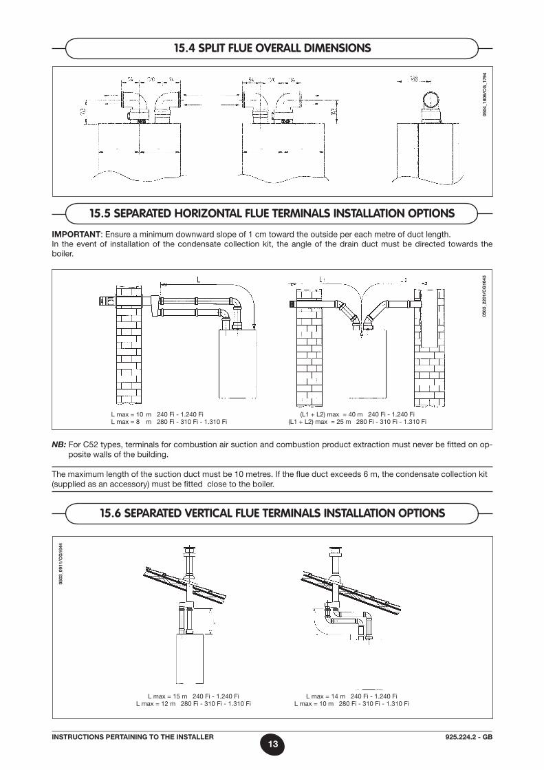
15.5 sepaRated HORizOntal flUe teRminals installatiOn OptiOns
Important: Ensure a minimum downward slope of 1 cm toward the outside per each metre of duct length.In the event of installation of the condensate collection kit, the angle of the drain duct must be directed towards the boiler.
NB: For C52 types, terminals for combustion air suction and combustion product extraction must never be fitted on op-posite walls of the building.
The maximum length of the suction duct must be 10 metres. If the flue duct exceeds 6 m, the condensate collection kit (supplied as an accessory) must be fitted close to the boiler.
15.4 split flUe OveRall dimensiOns
0504
_180
6/c
G_1
794
0503
_091
1/c
G16
44
15.6 sepaRated veRtical flUe teRminals installatiOn OptiOns
(L1 + L2) max = 40 m 240 Fi - 1.240 Fi(L1 + L2) max = 25 m 280 Fi - 310 Fi - 1.310 Fi
L max = 10 m 240 Fi - 1.240 FiL max = 8 m 280 Fi - 310 Fi - 1.310 Fi
L max = 15 m 240 Fi - 1.240 FiL max = 12 m 280 Fi - 310 Fi - 1.310 Fi
L max = 14 m 240 Fi - 1.240 Fi L max = 10 m 280 Fi - 310 Fi - 1.310 Fi
14925.224.2 - GBInstrUctIons pertaInInG to tHe Installer
16. cOnnectinG tHe mains sUpply
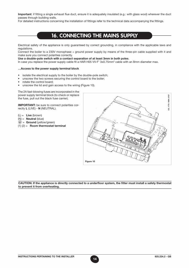
Electrical safety of the appliance is only guaranteed by correct grounding, in compliance with the applicable laws and regulations.Connect the boiler to a 230V monophase + ground power supply by means of the three-pin cable supplied with it and make sure you connect polarities correctly.Use a double-pole switch with a contact separation of at least 3mm in both poles.In case you replace the power supply cable fit a HaR H05 VV-F’ 3x0.75mm2 cable with an 8mm diameter max.
…access to the power supply terminal block
• isolatetheelectricalsupplytotheboilerbythedouble-poleswitch;• unscrewthetwoscrewssecuringthecontrolboardtotheboiler;• rotatethecontrolboard;• unscrewthelidandgainaccesstothewiring(Figure10).
Figure 10
The 2a fast-blowing fuses are in cor po rated in the power supply terminal block (to check or replace the fuse, pull out the black fuse carrier).
Important: be sure to connect polarities cor-rectly l (LIVE) - n (NEUTRaL).
(L) = live (brown)(N) = neutral (blue) = Ground (yellow/green)(1) (2) = room thermostat terminal
Important: if fitting a single exhaust flue duct, ensure it is adequately insulated (e.g.: with glass wool) wherever the duct passes through building walls.For detailed instructions concerning the installation of fittings refer to the technical data accompanying the fittings.
caUtIon: If the appliance is directly connected to a underfloor system, the fitter must install a safety thermostat to prevent it from overheating.
cG
_177
0 /
0904
_070
7
15925.224.2 - GBInstrUctIons pertaInInG to tHe Installer
a Qualified Service Engineer may adapt this boiler to operate with natural gas (G. 20) or with liquid gas (G. 31).
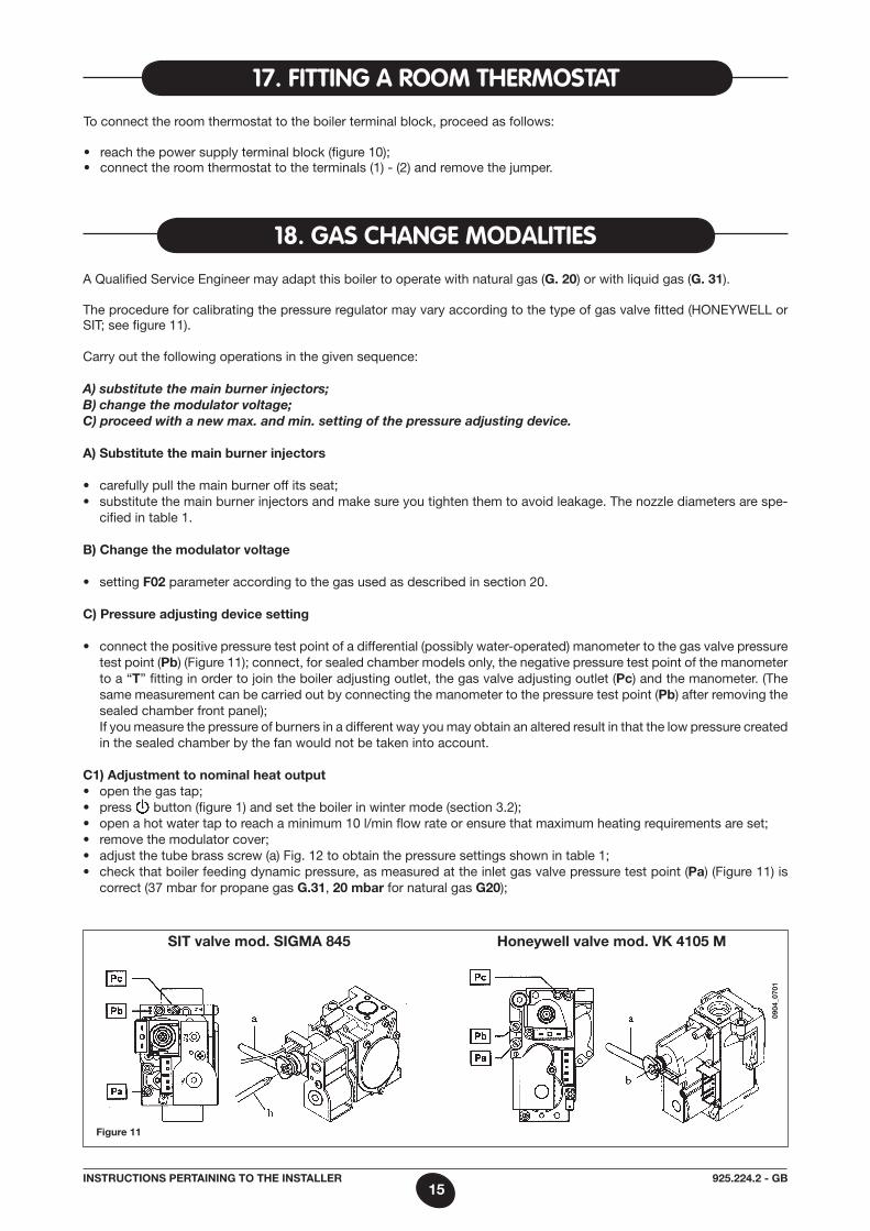
The procedure for calibrating the pressure regulator may vary according to the type of gas valve fitted (HONEY WELL or SIT; see figure 11).
Carry out the following ope rations in the given sequence:
A) substitute the main burner injectors;B) change the modulator voltage;C) proceed with a new max. and min. setting of the pressure adjusting device.
a) substitute the main burner injectors
• carefullypullthemainburneroffitsseat;• substitutethemainburnerinjectorsandmakesureyoutightenthemtoavoidleakage.Thenozzlediametersarespe-
cified in table 1.
B) change the modulator voltage
• settingF02 parameter according to the gas used as described in section 20.
c) pressure adjusting device setting
• connectthepositivepressuretestpointofadifferential(possiblywater-operated)manometertothegasvalvepressuretest point (pb) (Figure 11); connect, for sealed chamber models only, the negative pressure test point of the manometer to a “t” fitting in order to join the boiler adjusting outlet, the gas valve adjusting outlet (pc) and the manometer. (The same measurement can be carried out by connecting the manometer to the pressure test point (pb) after removing the sealed chamber front panel);
If you measure the pressure of burners in a different way you may obtain an altered result in that the low pressure created in the sealed chamber by the fan would not be taken into account.
c1) adjustment to nominal heat output• openthegastap;• press button (figure 1) and set the boiler in winter mode (section 3.2);• openahotwatertaptoreachaminimum10l/minflowrateorensurethatmaximumheatingrequirementsareset;• removethemodulatorcover;• adjustthetubebrassscrew(a)Fig.12toobtainthepressuresettingsshownintable1;• checkthatboilerfeedingdynamicpressure,asmeasuredattheinletgasvalvepressuretestpoint(pa) (Figure 11) is
correct (37 mbar for propane gas G.31, 20 mbar for natural gas G20);
18. Gas cHanGe mOdalities
17. fittinG a ROOm tHeRmOstat
To connect the room thermostat to the boiler terminal block, proceed as follows:
• reachthepowersupplyterminalblock(figure10);• connecttheroomthermostattotheterminals(1)-(2)andremovethejumper.
Figure 11
sIt valve mod. sIGma 845 Honeywell valve mod. vK 4105 m
0904
_070
1
16925.224.2 - GBInstrUctIons pertaInInG to tHe Installer
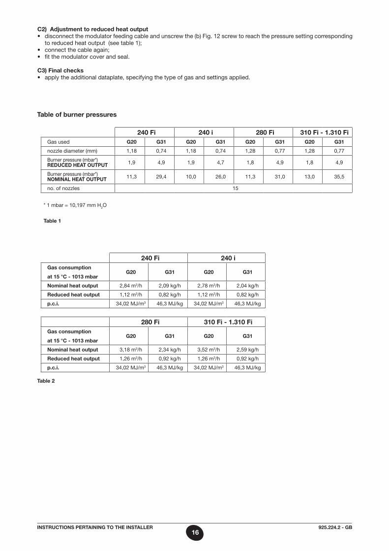
table of burner pressures
240 Fi 240 i 280 Fi 310 Fi - 1.310 FiGas used G20 G31 G20 G31 G20 G31 G20 G31
nozzle diameter (mm) 1,18 0,74 1,18 0,74 1,28 0,77 1,28 0,77
Burner pressure (mbar*) redUced Heat oUtpUt 1,9 4,9 1,9 4,7 1,8 4,9 1,8 4,9
Burner pressure (mbar*) nomInal Heat oUtpUt 11,3 29,4 10,0 26,0 11,3 31,0 13,0 35,5
no. of nozzles 15
* 1 mbar = 10,197 mm H2O
table 1
240 Fi 240 iGas consumption
at 15 °c - 1013 mbarG20 G31 G20 G31
nominal heat output 2,84 m3/h 2,09 kg/h 2,78 m3/h 2,04 kg/h
reduced heat output 1,12 m3/h 0,82 kg/h 1,12 m3/h 0,82 kg/h
p.c.i. 34,02 mJ/m3 46,3 mJ/kg 34,02 mJ/m3 46,3 mJ/kg
280 Fi 310 Fi - 1.310 FiGas consumption
at 15 °c - 1013 mbarG20 G31 G20 G31
nominal heat output 3,18 m3/h 2,34 kg/h 3,52 m3/h 2,59 kg/h
reduced heat output 1,26 m3/h 0,92 kg/h 1,26 m3/h 0,92 kg/h
p.c.i. 34,02 mJ/m3 46,3 mJ/kg 34,02 mJ/m3 46,3 mJ/kg
table 2
c2) adjustment to reduced heat output• disconnectthemodulatorfeedingcableandunscrewthe(b)Fig.12screwtoreachthepressuresettingcorresponding
to reduced heat output (see table 1);• connectthecableagain;• fitthemodulatorcoverandseal.
c3) Final checks• applytheadditionaldataplate,specifyingthetypeofgasandsettingsapplied.
17925.224.2 - GBInstrUctIons pertaInInG to tHe Installer
19. infORmatiOn display
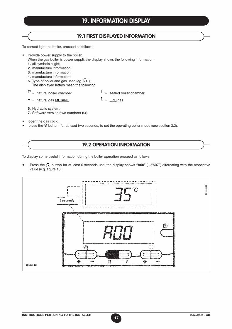
19.2 OpeRatiOn infORmatiOn
To display some useful information during the boiler operation proceed as follows:
• Press the ( ) button for at least 6 seconds until the display shows “a00” (…“a07”) alternating with the respective value (e.g. figure 13);
Figure 13
To correct light the boiler, proceed as follows:
• Providepowersupplytotheboiler. When the gas boiler is power supplì, the display shows the following information: 1. all symbols alight; 2. manufacture information; 3. manufacture information; 4. manufacture information; 5. Type of boiler and gas used (eg. ). The displayed letters mean the following:
= natural boiler chamber = sealed boiler chamber
= natural gas mETaNE = LPG gas
6. Hydraulic system; 7. Software version (two numbers x.x);
• openthegascock;• pressthe button, for at least two seconds, to set the operating boiler mode (see section 3.2).
19.1 fiRst displayed infORmatiOn
0610
_260
6
18925.224.2 - GBInstrUctIons pertaInInG to tHe Installer
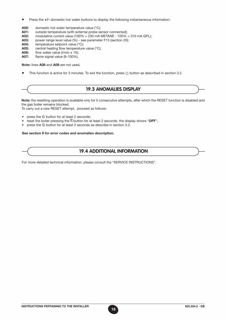
• Press the +/- domestic hot water buttons to display the following instantaneous information:
a00: domestic hot water temperature value (°C);a01: outside temperature (with external probe sensor connected);a02: modulatine current value (100% = 230 ma mETaNE - 100% = 310 ma GPL); a03: power range level value (%) - see parameter F13 (section 20);a04: temperature setpoint value (°C);a05: central heating flow temperature value (°C);a06: flow water value (l/min x 10);a07: flame signal value (8-100%).
note: lines a08 and a09 are not used.
• This function is active for 3 minutes. To exit the function, press button as described in section 3.2.
note: the resetting operation is available only for 5 consecutive attempts, after which the RESET function is disabled and the gas boiler remains blocked. To carry out a new RESET attempt, proceed as follows:
• pressthe button for at least 2 seconds; • resettheboilerpressingthe button for at least 2 seconds, the display shows “oFF”;.• pressthe button for at least 2 seconds as describe in section 3.2.
see section 9 for error codes and anomalies description.
19.3 anOmalies display
For more detailed technical information, please consult the “SERVICE INSTRUCTIONS”.
19.4 additiOnal infORmatiOn
19925.224.2 - GBInstrUctIons pertaInInG to tHe Installer
20. paRameteRs settinG
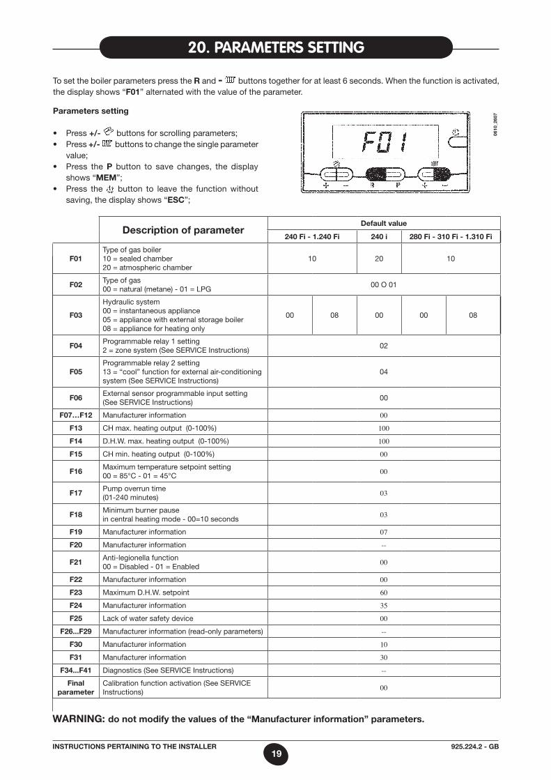
To set the boiler parameters press the r and - buttons together for at least 6 seconds. When the function is activated, the display shows “F01” alternated with the value of the parameter.
parameters setting
• Press+/- buttons for scrolling parameters;• Press+/- buttons to change the single parameter
value;• Press the p button to save changes, the display
shows “mem”;• Press the button to leave the function without
saving, the display shows “esc”;
description of parameterdefault value
240 Fi - 1.240 Fi 240 i 280 Fi - 310 Fi - 1.310 Fi
F01Type of gas boiler10 = sealed chamber20 = atmospheric chamber
10 20 10
F02Type of gas00 = natural (metane) - 01 = LPG
00 O 01
F03
Hydraulic system00 = instantaneous appliance05 = appliance with external storage boiler08 = appliance for heating only
00 08 00 00 08
F04Programmable relay 1 setting2 = zone system (See SERVICE Instructions)
02
F05Programmable relay 2 setting13 = “cool” function for external air-conditioning system (See SERVICE Instructions)
04
F06External sensor programmable input setting(See SERVICE Instructions)
00
F07…F12 manufacturer information 00
F13 CH max. heating output (0-100%) 100
F14 D.H.W. max. heating output (0-100%) 100
F15 CH min. heating output (0-100%) 00
F16maximum temperature setpoint setting00 = 85°C - 01 = 45°C 00
F17Pump overrun time(01-240 minutes) 03
F18minimum burner pausein central heating mode - 00=10 seconds 03
F19 manufacturer information 07
F20 manufacturer information --
F21anti-legionella function00 = Disabled - 01 = Enabled 00
F22 manufacturer information 00
F23 maximum D.H.W. setpoint 60
F24 manufacturer information 35
F25 Lack of water safety device 00
F26...F29 manufacturer information (read-only parameters) --
F30 manufacturer information 10
F31 manufacturer information 30
F34...F41 Diagnostics (See SERVICE Instructions) --
Final parameter
Calibration function activation (See SERVICE Instructions) 00
WarnInG: do not modify the values of the “manufacturer information” parameters.
0610
_260
7
20925.224.2 - GBInstrUctIons pertaInInG to tHe Installer
The boiler has been designed in full compliance with European reference standards and in particular is equipped with the following:
• Air pressure switch for forced draught model (240 Fi - 280 Fi - 310 Fi - 1.240 Fi - 1.310 Fi) This switch allows the burner to switch on provided the exhaust flue duct efficiency is perfect. In the event of one of the following faults: • theflueterminalisobstructed; • theventuriisobstructed; • thefanisblocked; • theconnectionbetweentheventuriandtheairpressureswitchisinterrupted; The boiler will stay on stand-by and the display shows error code E03 (see section 9).
• Flue thermostat for natural draught (model 240 i) This device has a sensor positioned on the left section of the flue extraction hood and shuts off the gas flow to the burner if the flue
duct is obstructed or in the event of draught failure. Under such conditions the boiler is blocked and the display shows E03 error (see section 9). To relight the main burner immediately, see section 9.
It is forbidden to disenable this safety device
• Overheat safety thermostat Thanks to a sensor placed on the heating flow, this thermostat interrupts the gas flow to the burner in case the water contained in
the primary circuit has overheated. Under such conditions the boiler is blocked and relighting will only be possible after the cause of the anomaly has been removed.
It is forbidden to disenable this safety device
• Flame ionization detector The flame sensing electrode, placed on the right of the burner, guarantees safety of operation in case of gas failure or incomplete
interlighting of the burner. The boiler is blocked after 3 relight attempt. See section 9 to RESET normal operating conditions.
• Hydraulic pressure sensor This device (3 - figure 24/25) enables the main burner only to be switched on if the system pressure is over 0.5 bars.
• Pump overrun for central heating circuit The electronically-controlled supplementary running of the pump lasts 3 minutes (F17 - Section 20), when the boiler is in the central
heating mode, after the burner has switched off due to a room thermostat or intervention.
• Pump overrun for domestic hot water circuit The electronic control system keeps the pump operating for 30 seconds in domestic hot water mode after the D.H.W. sensor has
switched off the burner.
• Frost protection device (central heating and domestic hot water systems) Boilers electronic management includes a “frost protection” function in the central heating system which operates the burner to reach
a heating flow temperature of 30°C when the system heating flow temperature drops below 5 °C. This function is enabled when the boiler is connected to electrical supply, the gas supply is on and the system pressure is as requi-
red.
• Lack of water circulation (probable pump jammed) If the water inside the primary circuit doesn’t circulate, the display shows E25 error (see section 9).
• Anti-block pump function In the event that no heat is required, the pump will automatically start up and operate for one minute during the following 24 hours. This function is operative when the boiler is powered.
• Three-way anti-blockage valve In the case of no heat is request for a period of 24 hours the three way valve carries out a complete commutation. This function is operative when the boiler is powered.
• Hydraulic safety valve (heating circuit) This device is set to 3 bar and is used for the heating circuit.
The safety valve should be connected to a siphoned drain. Use as a means of draining the heating circuit is strictly prohibited.
• antilegionella function (models 1. 240 Fi - 1.310 Fi with d.H.W. storage tank) The antilegionella function is NOT enable. To enable the function, set the parameter F21=01 (as described in section 20). When the function is activated, at weekly intervals
the boiler’s electronic control system brings the water inside the hot water tank to a temperature above 60°C (the function is only operational if the water has never exceeded 60°C in the previous 7 days).
note: domestic hot water is guaranteed even if the NTC sensor (5 - figure 24 - 25) is damaged. In this case, the temperature control is carried out by the boiler flow temperature.
21. cOntROl and OpeRatiOn devices
21925.224.2 - GBInstrUctIons pertaInInG to tHe Installer
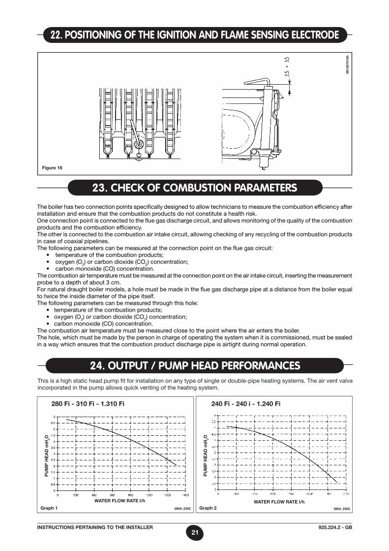
22. pOsitiOninG Of tHe iGnitiOn and flame sensinG electROde
Figure 16
9912
0701
00
The boiler has two connection points specifically designed to allow technicians to measure the combustion efficiency after installation and ensure that the combustion products do not constitute a health risk.One connection point is connected to the flue gas discharge circuit, and allows monitoring of the quality of the combustion products and the combustion efficiency.The other is connected to the combustion air intake circuit, allowing checking of any recycling of the combustion products in case of coaxial pipelines.The following parameters can be measured at the connection point on the flue gas circuit: • temperatureofthecombustionproducts; • oxygen(O2) or carbon dioxide (CO2) concentration; • carbonmonoxide(CO)concentration.The combustion air temperature must be measured at the connection point on the air intake circuit, inserting the measurement probe to a depth of about 3 cm.For natural draught boiler models, a hole must be made in the flue gas discharge pipe at a distance from the boiler equal to twice the inside diameter of the pipe itself.The following parameters can be measured through this hole: • temperatureofthecombustionproducts; • oxygen(O2) or carbon dioxide (CO2) concentration; • carbonmonoxide(CO)concentration.The combustion air temperature must be measured close to the point where the air enters the boiler. The hole, which must be made by the person in charge of operating the system when it is commissioned, must be sealed in a way which ensures that the combustion product discharge pipe is airtight during normal operation.
23. cHeck Of cOmBUstiOn paRameteRs
This is a high static head pump fit for installation on any type of single or double-pipe heating systems. The air vent valve incorporated in the pump allows quick venting of the heating system.
Graph 1
24. OUtpUt / pUmp Head peRfORmances
Water FloW rate l/h
pU
mp
He
ad
mH
2o
0604_2302 Graph 2Water FloW rate l/h
pU
mp
He
ad
mH
2o
280 Fi - 310 Fi - 1.310 Fi
0604_2303
240 Fi - 240 i - 1.240 Fi
22925.224.2 - GBInstrUctIons pertaInInG to tHe Installer
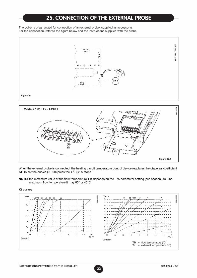
25. cOnnectiOn Of tHe exteRnal pROBe
Kt curves
Graph 3
tm = flow temperature (°C)te = external temperature (°C)
0603
_030
5
0603
_030
6
Graph 4
The boiler is prearranged for connection of an external probe (supplied as accessory).For the connection, refer to the figure below and the instructions supplied with the probe.
Figure 17
When the external probe is connected, the heating circuit temperature control device regulates the dispersal coefficient Kt. To set the curves (0…90) press the +/- buttons.
note: the maximum value of the flow temperature tm depends on the F16 parameter setting (see section 20). The maximum flow temperature it may 85° or 45°C.
0610
_130
1 /
cG
_185
5
CN 5
0605
_160
4
Figure 17.1
models 1.310 Fi - 1.240 Fi
23925.224.2 - GBInstrUctIons pertaInInG to tHe Installer
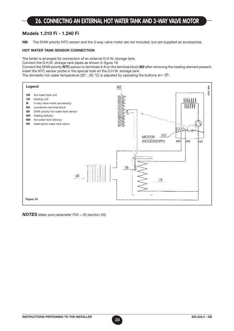
models 1.310 Fi - 1.240 Fi
nB: The DHW priority NTC sensor and the 3-way valve motor are not included, but are supplied as accessories.
Hot Water tanK sensor connectIon
The boiler is arranged for connection of an external D.H.W. storage tank. Connect the D.H.W. storage tank pipes as shown in figure 18.Connect the DHW priority ntc sensor to terminals 5-6 on the terminal block m2 after removing the heating element present. Insert the NTC sensor probe in the special hole on the D.H.W. storage tank. The domestic hot water temperature (35°...65 °C) is adjusted by operating the buttons +/- .
26. cOnnectinG an exteRnal HOt WateR tank and 3-Way valve mOtOR
Figure 18
legend
UB hot water tank unit
Ur heating unit
m 3-way valve motor (accessory)
m2 connection terminal block
sB DHW priority hot water tank sensor
mr heating delivery
mB hot water tank delivery
rr heating/hot water tank return
mOTOR(aCCESSORY)
NOTES Make sure parameter F03 = 05 (section 20).
0702
_160
2
24925.224.2 - GBInstrUctIons pertaInInG to tHe Installer
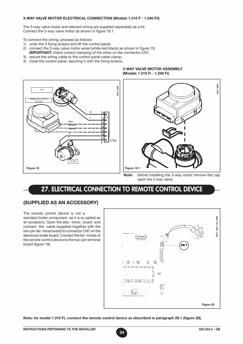
3-Way valve motor electrIcal connectIon (models 1.310 F - 1.240 Fii)
The 3-way valve motor and relevant wiring are supplied separately as a kit.Connect the 3-way valve motor as shown in figure 19.1.
To connect the wiring, proceed as follows:1) undo the 3 fixing screws and lift the control panel;2) connect the 3-way valve motor wires (white-red-black) as shown in figure 19; IMPORTANT: check correct clamping of the wires on the connector CN1.3) secure the wiring cable to the control panel cable clamp; 4) close the control panel, securing it with the fixing screws.
0512
_120
4
FAN
THREE-WAY VALVE MOTOR
PUMP
WHITE
rEd
BLACK
M
C
M
C
CN1
3-Way valve motor assemBly (models 1.310 Fi - 1.240 Fi)
0512
_200
5
note: before installing the 3-way motor remove the cap upon the 3 way valve.
Figure 19 Figure 19.1
(sUpplIed as an accessory)
The remote control device is not astandard boiler component as it is su pplied as an accessory. Open the elec- tronic board and connect the cable (supplied together with the two-pin ter- minal board) to connector CN7 on the electronic boiler board. Connect the ter- minals of the remote control device to the two-pin terminal board (figure 19).
27. electRical cOnnectiOn tO RemOte cOntROl device
Figure 20
note: for model 1.310 Fi, connect the remote control device as described in paragraph 28.1 (figure 20).
0610
_130
2 /
cG
_185
6
CN 7
25925.224.2 - GBInstrUctIons pertaInInG to tHe Installer
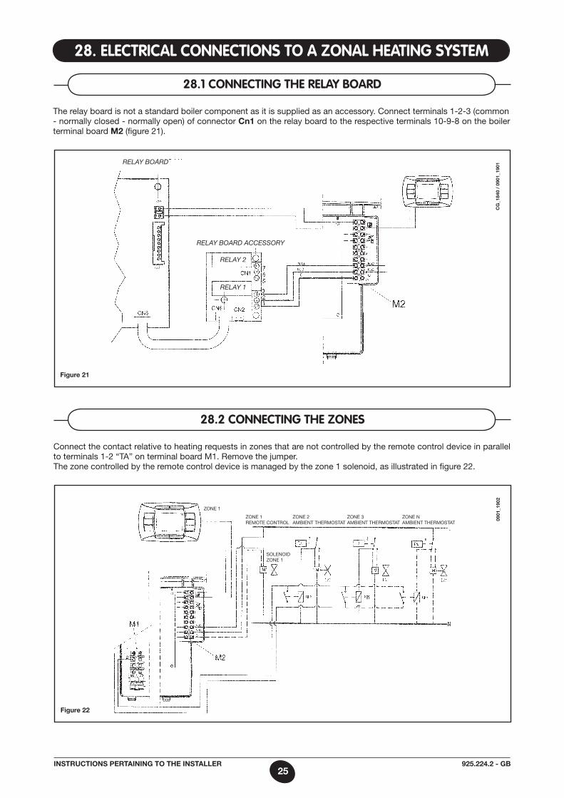
28. electRical cOnnectiOns tO a zOnal HeatinG system
The relay board is not a standard boiler component as it is supplied as an accessory. Connect terminals 1-2-3 (common- normally closed - normally open) of connector cn1 on the relay board to the respective terminals 10-9-8 on the boiler terminal board m2 (figure 21).
28.1 cOnnectinG tHe Relay BOaRd
relay boarD
relay boarD aCCessory
relay 2
relay 1
cG
_184
0 /
0901
_190
1
Figure 21
Connect the contact relative to heating requests in zones that are not controlled by the remote control device in parallel to terminals 1-2 “Ta” on terminal board m1. Remove the jumper.The zone controlled by the remote control device is managed by the zone 1 solenoid, as illustrated in figure 22.
28.2 cOnnectinG tHe zOnes
ZONE 1
ZONE 1 REmOTE CONTROL
0901
_190
2
Figure 22
SOLENOID ZONE 1
ZONE 2 amBIENT THERmOSTaT
ZONE 3 amBIENT THERmOSTaT
ZONE N amBIENT THERmOSTaT
26925.224.2 - GBInstrUctIons pertaInInG to tHe Installer
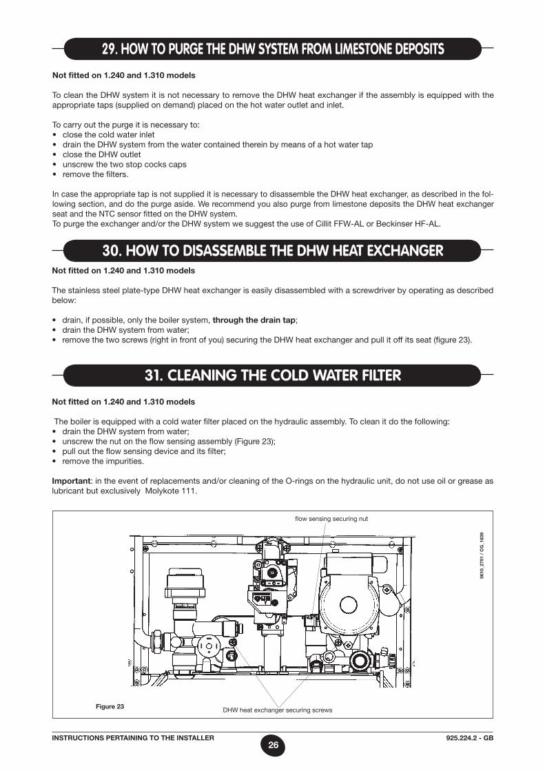
not fitted on 1.240 and 1.310 models To clean the DHW system it is not necessary to remove the DHW heat exchanger if the assembly is equipped with the appropriate taps (supplied on demand) placed on the hot water outlet and inlet.
To carry out the purge it is necessary to:• closethecoldwaterinlet• draintheDHWsystemfromthewatercontainedthereinbymeansofahotwatertap• closetheDHWoutlet• unscrewthetwostopcockscaps• removethefilters.
In case the appropriate tap is not supplied it is necessary to disassemble the DHW heat exchanger, as described in the fol-lowing section, and do the purge aside. We recommend you also purge from limestone deposits the DHW heat exchanger seat and the NTC sensor fitted on the DHW system. To purge the exchanger and/or the DHW system we suggest the use of Cillit FFW-aL or Beckinser HF-aL.
29. HOW tO pURGe tHe dHW system fROm limestOne depOsits
not fitted on 1.240 and 1.310 models The stainless steel plate-type DHW heat exchanger is easily disassembled with a screwdriver by operating as described below:
• drain,ifpossible,onlytheboilersystem,through the drain tap;• draintheDHWsystemfromwater;• removethetwoscrews(rightinfrontofyou)securingtheDHWheatexchangerandpullitoffitsseat(figure23).
30. HOW tO disassemBle tHe dHW Heat excHanGeR
not fitted on 1.240 and 1.310 models The boiler is equipped with a cold water filter placed on the hydraulic assembly. To clean it do the following:• draintheDHWsystemfromwater;• unscrewthenutontheflowsensingassembly(Figure23);• pullouttheflowsensingdeviceanditsfilter;• removetheimpurities.
Important: in the event of replacements and/or cleaning of the O-rings on the hydraulic unit, do not use oil or grease as lubricant but exclusively molykote 111.
31. cleaninG tHe cOld WateR filteR
0610
_270
1 /
cG
_183
9
Figure 23 DHW heat exchanger securing screws
flow sensing securing nut
27925.224.2 - GBInstrUctIons pertaInInG to tHe Installer
Figure 24
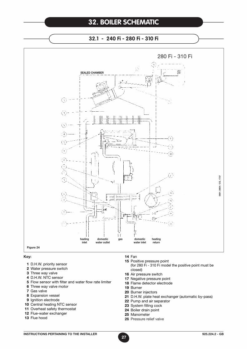
32. BOileR scHematic
32.1 - 240 fi - 280 fi - 310 fi
Key:
1 D.H.W. priority sensor 2 Water pressure switch 3 Three way valve 4 D.H.W. NTC sensor 5 Flow sensor with filter and water flow rate limiter 6 Three way valve motor 7 Gas valve 8 Expansion vessel 9 Ignition electrode 10 Central heating NTC sensor 11 Overheat safety thermostat 12 Flue-water exchanger 13 Flue hood
14 Fan 15 Positive pressure point (for 280 Fi - 310 Fi model the positive point must be
closed) 16 air pressure switch 17 Negative pressure point 18 Flame detector electrode 19 Burner 20 Burner injectors 21 D.H.W. plate heat exchanger (automatic by-pass) 22 Pump and air separator 23 System filling cock 24 Boiler drain point 25 manometer 26 Pressure relief valve
heating domestic gas domestic heating inlet water outlet water inlet return
sealed cHamBer
0901
_080
4 /
cG
_173
7
280 Fi - 310 Fi
28925.224.2 - GBInstrUctIons pertaInInG to tHe Installer
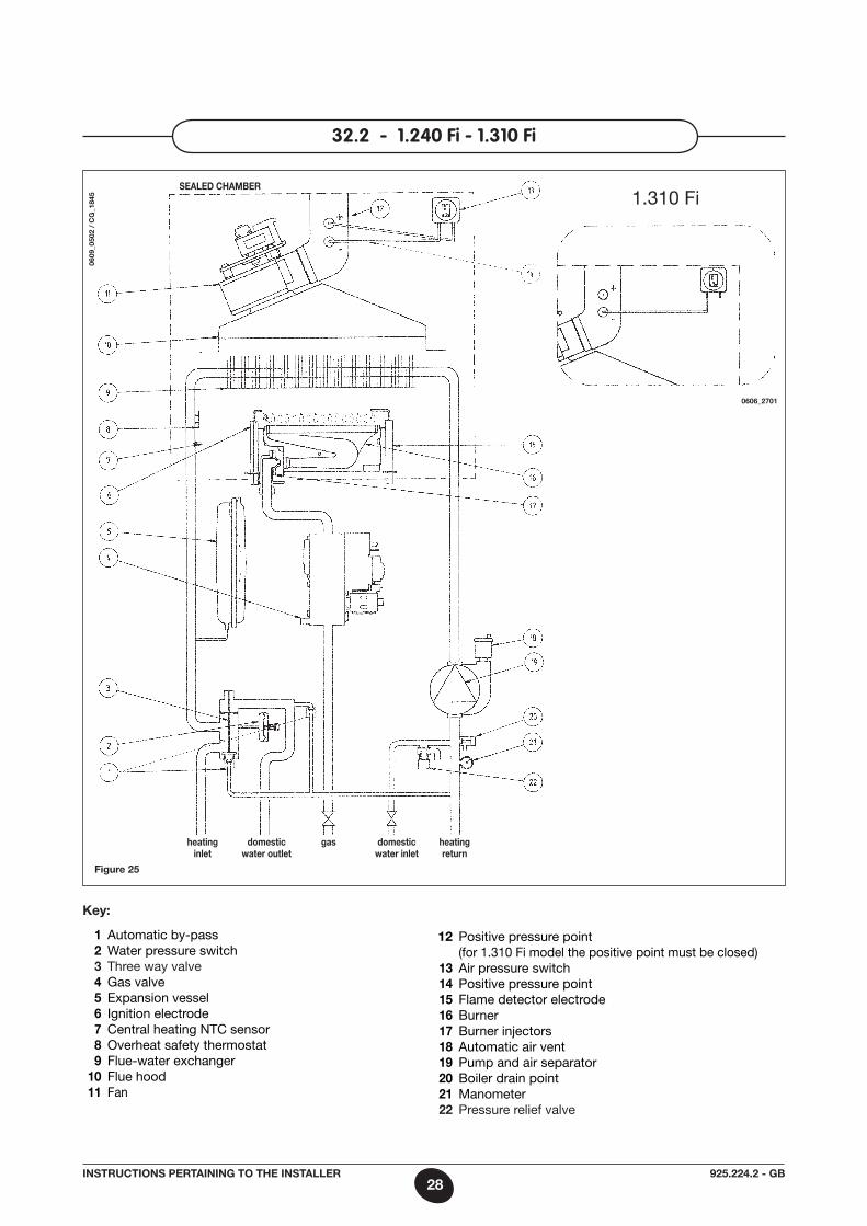
Figure 25
0609
_050
2 /
cG
_184
5
32.2 - 1.240 fi - 1.310 fi
sealed cHamBer
0606_2701
1.310 Fi
Key:
1 automatic by-pass 2 Water pressure switch 3 Three way valve 4 Gas valve 5 Expansion vessel 6 Ignition electrode 7 Central heating NTC sensor 8 Overheat safety thermostat 9 Flue-water exchanger 10 Flue hood 11 Fan
12 Positive pressure point (for 1.310 Fi model the positive point must be closed) 13 air pressure switch 14 Positive pressure point 15 Flame detector electrode 16 Burner 17 Burner injectors 18 automatic air vent 19 Pump and air separator 20 Boiler drain point 21 manometer 22 Pressure relief valve
heating domestic gas domestic heating inlet water outlet water inlet return
29925.224.2 - GBInstrUctIons pertaInInG to tHe Installer
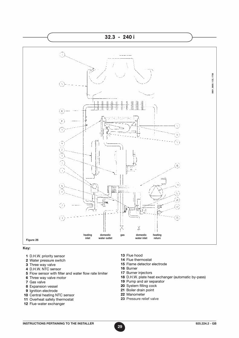
32.3 - 240 i
Figure 26
Key:
1 D.H.W. priority sensor 2 Water pressure switch 3 Three way valve 4 D.H.W. NTC sensor 5 Flow sensor with filter and water flow rate limiter 6 Three way valve motor 7 Gas valve 8 Expansion vessel 9 Ignition electrode 10 Central heating NTC sensor 11 Overheat safety thermostat 12 Flue-water exchanger
13 Flue hood 14 Flue thermostat 15 Flame detector electrode 16 Burner 17 Burner injectors 18 D.H.W. plate heat exchanger (automatic by-pass) 19 Pump and air separator 20 System filling cock 21 Boiler drain point 22 manometer 23 Pressure relief valve
heating domestic gas domestic heating inlet water outlet water inlet return
0901
_080
5 /
cG
_173
8
30925.224.2 - GBInstrUctIons pertaInInG to tHe Installer
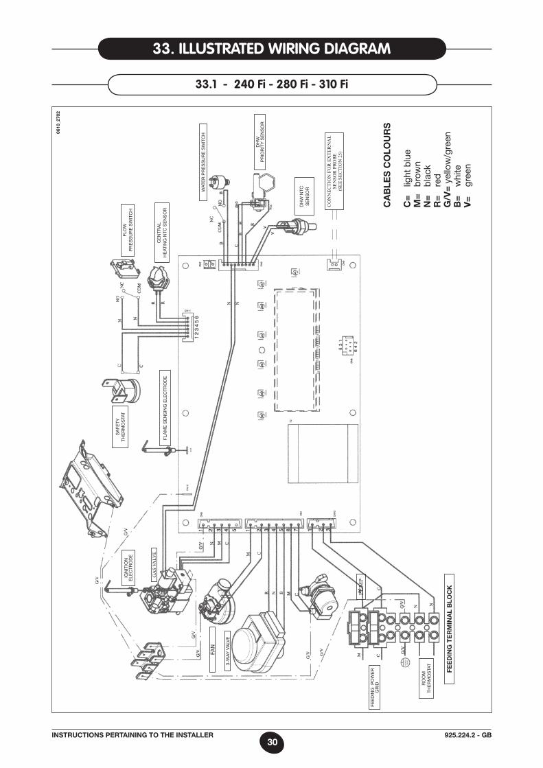
33. illUstRated WiRinG diaGRam
33.1 - 240 fi - 280 fi - 310 fi
FaN
FEE
DIN
G P
OW
ER
G
RID
Sa
FETY
TH
ER
mO
STa
TIG
NIT
ION
E
LEC
TRO
DE
3-W
aY V
aLV
E
CE
NTR
aL
HE
aTIN
G N
TC S
EN
SO
R
FLO
W
PR
ES
SU
RE
SW
ITC
H
RO
Om
TH
ER
mO
STa
T
FLa
mE
SE
NS
ING
ELE
CTR
OD
E
WaT
ER
PR
ES
SU
RE
SW
ITC
H
DH
W
PR
IOR
ITY
SE
NS
OR
PU
MP
DH
W N
TC
SE
NS
OR
Fee
dIn
G t
er
mIn
al
Blo
cK
GA
S VA
LVE
ca
Ble
s c
olo
Ur
s
c=
lig
ht b
lue
m=
b
row
nn
=
bla
ckr
=
red
G/v
= y
ello
w/g
reen
B=
w
hite
v=
gr
een
cO
NN
Ec
TiO
N F
OR
Ex
TE
RN
AL
SE
NSO
R P
RO
bE
(S
EE
SE
cT
iON
25)
0610
_270
2
31925.224.2 - GBInstrUctIons pertaInInG to tHe Installer
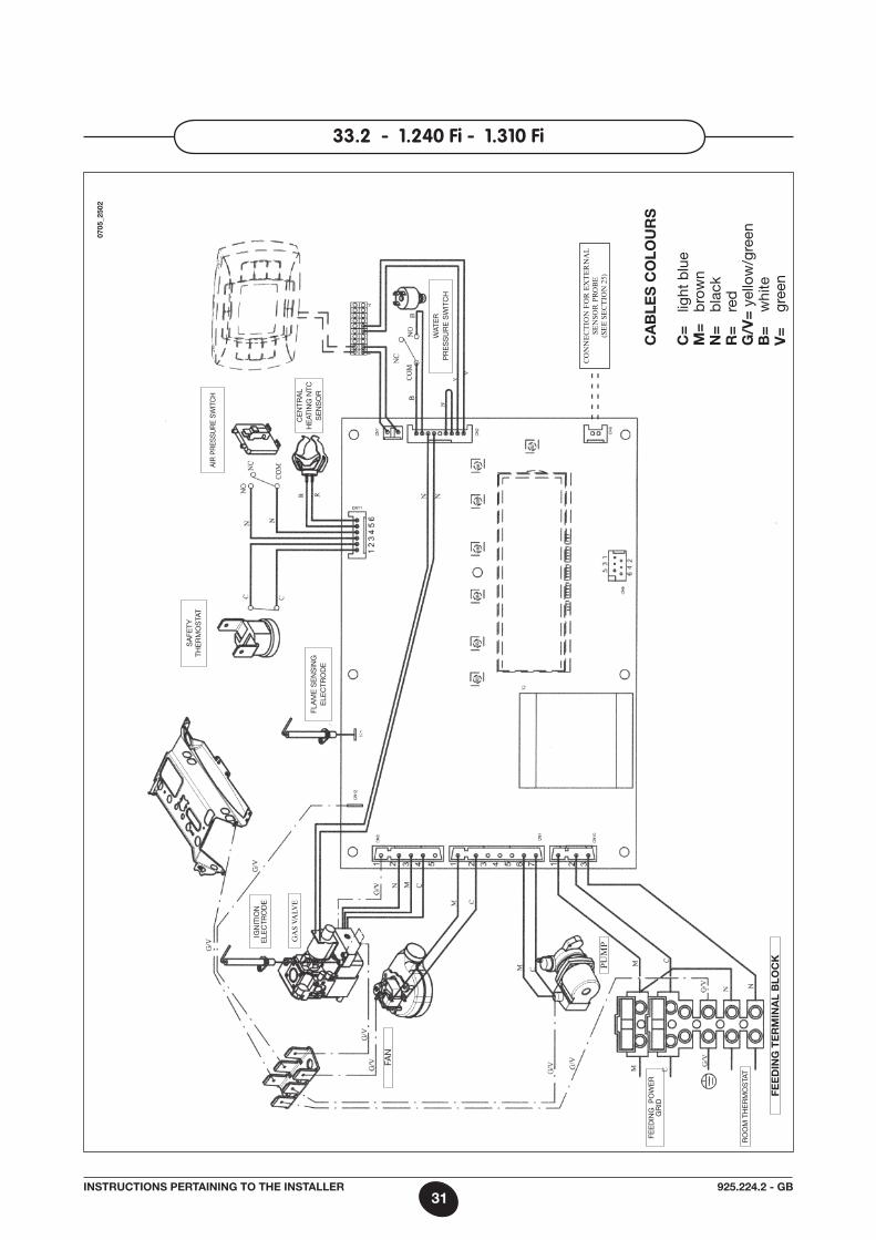
33.2 - 1.240 fi - 1.310 fi
0705
_250
2
- - -
- -- -
- - -
ca
Ble
s c
olo
Ur
s
c=
lig
ht b
lue
m=
b
row
nn
=
bla
ckr
=
red
G/v
= y
ello
w/g
reen
B=
w
hite
v=
gr
een
PU
MP
FEE
DIN
G P
OW
ER
G
RID
RO
Om
TH
ER
mO
STa
T
Fee
dIn
G t
er
mIn
al
Blo
cK
FaN
IGN
ITIO
N
ELE
CTR
OD
E
GA
S VA
LVE
WaT
ER
P
RE
SS
UR
E S
WIT
CH
CE
NTR
aL
HE
aTIN
G N
TC
SE
NS
OR
aIR
PR
ESS
UR
E S
WIT
CH
Sa
FETY
TH
ER
mO
STa
T
FLa
mE
SE
NS
ING
E
LEC
TRO
DE
cO
NN
Ec
TiO
N F
OR
Ex
TE
RN
AL
SE
NSO
R P
RO
bE
(S
EE
SE
cT
iON
25)
32925.224.2 - GBInstrUctIons pertaInInG to tHe Installer
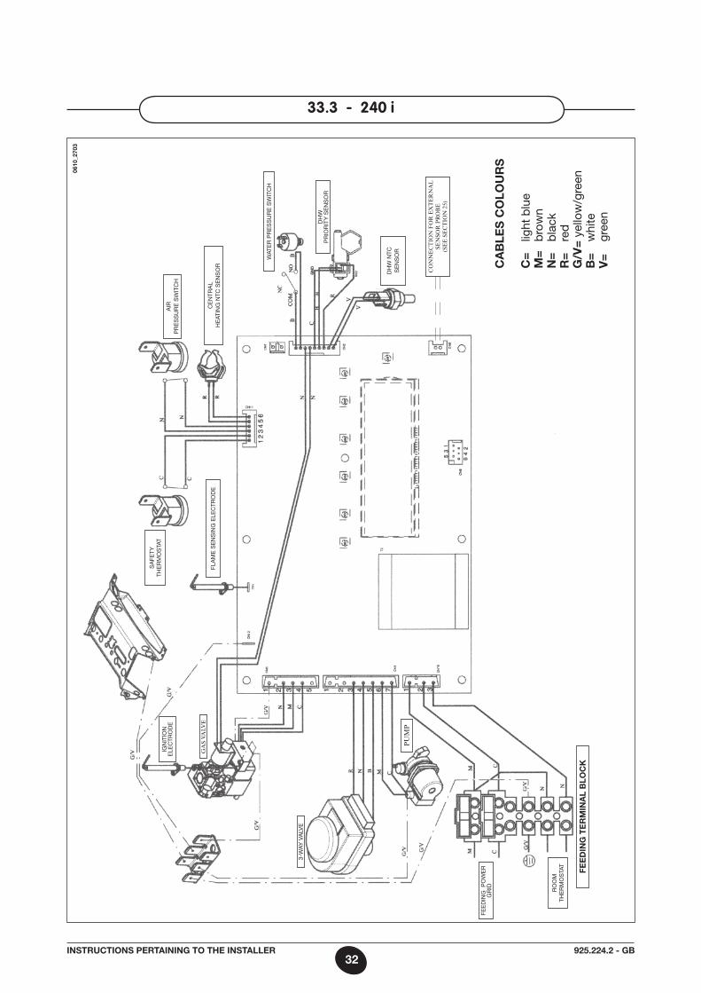
33.3 - 240 i
FEE
DIN
G P
OW
ER
G
RID
Sa
FETY
TH
ER
mO
STa
TIG
NIT
ION
E
LEC
TRO
DE
3-W
aY V
aLV
E
CE
NTR
aL
HE
aTIN
G N
TC S
EN
SO
R
aIR
P
RE
SS
UR
E S
WIT
CH
RO
Om
TH
ER
mO
STa
T
FLa
mE
SE
NS
ING
ELE
CTR
OD
E
WaT
ER
PR
ES
SU
RE
SW
ITC
H
DH
W
PR
IOR
ITY
SE
NS
OR
PU
MP
DH
W N
TC
SE
NS
OR
Fee
dIn
G t
er
mIn
al
Blo
cK
GA
S VA
LVE
ca
Ble
s c
olo
Ur
s
c=
lig
ht b
lue
m=
b
row
nn
=
bla
ckr
=
red
G/v
= y
ello
w/g
reen
B=
w
hite
v=
gr
een
0610
_270
3
cO
NN
Ec
TiO
N F
OR
Ex
TE
RN
AL
SE
NSO
R P
RO
bE
(S
EE
SE
cT
iON
25)
33925.224.2 - GBInstrUctIons pertaInInG to tHe Installer
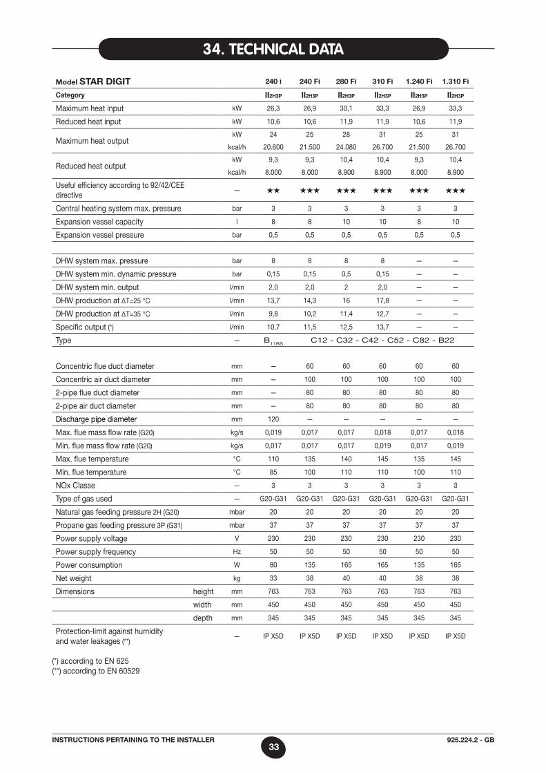
34. tecHnical data
model star dIGIt 240 i 240 Fi 280 Fi 310 Fi 1.240 Fi 1.310 Fi
category II2H3p II2H3p II2H3p II2H3p II2H3p II2H3p
maximum heat input kW 26,3 26,9 30,1 33,3 26,9 33,3
Reduced heat input kW 10,6 10,6 11,9 11,9 10,6 11,9
maximum heat output kW 24 25 28 31 25 31
kcal/h 20.600 21.500 24.080 26.700 21.500 26.700
Reduced heat output kW 9,3 9,3 10,4 10,4 9,3 10,4
kcal/h 8.000 8.000 8.900 8.900 8.000 8.900
Useful efficiency according to 92/42/CEE directive
— ★★ ★★★ ★★★ ★★★ ★★★ ★★★
Central heating system max. pressure bar 3 3 3 3 3 3
Expansion vessel capacity l 8 8 10 10 8 10
Expansion vessel pressure bar 0,5 0,5 0,5 0,5 0,5 0,5
DHW system max. pressure bar 8 8 8 8 — —
DHW system min. dynamic pressure bar 0,15 0,15 0,5 0,15 — —
DHW system min. output l/min 2,0 2,0 2 2,0 — —
DHW production at ∆T=25 °C l/min 13,7 14,3 16 17,8 — —
DHW production at ∆T=35 °C l/min 9,8 10,2 11,4 12,7 — —
Specific output (*) l/min 10,7 11,5 12,5 13,7 — —
Type — B11BS C12 - C32 - C42 - C52 - C82 - B22
Concentric flue duct diameter mm — 60 60 60 60 60
Concentric air duct diameter mm — 100 100 100 100 100
2-pipe flue duct diameter mm — 80 80 80 80 80
2-pipe air duct diameter mm — 80 80 80 80 80
Discharge pipe diameter mm 120 — — — — —
max. flue mass flow rate (G20) kg/s 0,019 0,017 0,017 0,018 0,017 0,018
min. flue mass flow rate (G20) kg/s 0,017 0,017 0,017 0,019 0,017 0,019
max. flue temperature °C 110 135 140 145 135 145
min. flue temperature °C 85 100 110 110 100 110
NOx Classe — 3 3 3 3 3 3
Type of gas used — G20-G31 G20-G31 G20-G31 G20-G31 G20-G31 G20-G31
Natural gas feeding pressure 2H (G20) mbar 20 20 20 20 20 20
Propane gas feeding pressure 3P (G31) mbar 37 37 37 37 37 37
Power supply voltage V 230 230 230 230 230 230
Power supply frequency Hz 50 50 50 50 50 50
Power consumption W 80 135 165 165 135 165
Net weight kg 33 38 40 40 38 38
Dimensions height mm 763 763 763 763 763 763
width mm 450 450 450 450 450 450
depth mm 345 345 345 345 345 345
Protection-limit against humidity and water leakages (**)
— IP X5D IP X5D IP X5D IP X5D IP X5D IP X5D
(*) according to EN 625 (**) according to EN 60529
34925.224.2 - ROINSTRUCŢIUNI PENTRU UTILIZATOR
Stimat client, Suntem siguri că noua noastră centrală va răspunde tuturor cerinţelor dv.Cumpărarea unuia dintre produsele noastre vă va satisface aşteptările: funcţionare optimă, simplitate şi uşurinţă în folosi-re. Nu aruncaţi acest manual fără a-l citi: în el veţi găsi informaţii foarte utile, care vă vor ajuta să utilizaţi centrala în mod corect şi eficient.Nu lăsaţi la îndemâna copiilor materialele de ambalaj (saci de plastic, polistiren etc.) deoarece reprezintă o potenţială sursă de pericol
1. Instrucţiuni înainte de instalare 352. Instrucţiuni înainte de punerea în funcţiune 353. Punerea în funcţiune a centralei 364. Reglarea temperaturii din circuitul de Încălzire Centrală (ÎC = CH) şi Apă Caldă Menajeră (A.C.M. = D.H.W.) 375. Umplerea centralei 386. Oprirea centralei 387. Modificarea tipului de gaz 388. Oprirea îndelungată a instalaţiei. Protecţia anti-îngheţ 389. Mesaje de eroare şi tabelul cu defecţiuni 3910. Instrucţiuni de întreţinere 39
11. Informaţii generale 4012. Instrucţiuni înainte de instalare 4013. Instalarea centralei 4114. Dimensiunile centralei 4115. Instalarea conductelor de gaze arse şi aer 4216. Conectarea la reţeaua electrică 4617. Instalarea unui termostat ambiental 4718. Modalităţi de modificare a tipului de gaz 4719. Afişaj informaţii 4920. Reglarea parametrilor 5121. Dispozitive de control şi funcţionare 5222. Poziţionarea electrodului-senzor pentru aprindere şi flacără 5323. Verificarea parametrilor de combustie 5324. Performanţe debit / înălţime de pompare 5325. Conectarea sondei externe 5426. Racordarea unei unităţi boiler externe şi a motorului vanei cu 3 5527. Cablajul electric al controlului telecomandat 5628. Cablajul electri la o instalaţie zonală 5729. Îndepărtarea calcarului din circuitul de apă menajeră 5830. Demontarea schimbătorului apă-apă 5831. Curăţarea filtrului pentru apă rece 5832. Schema centralei 5933. Schema ilustrată a conexiunilor 6234. Date tehnice 65
Cuprins
instruCţiuni pentru utilizator
instruCţiuni pentru instalator
Centralele noastre poartă marca CE, în conformitate cu cerinţele de bază din următoarele Direc-tive:- Directiva Aparate cu Gaz 90/396/CEE- Directiva Eficienţă 92/42/CEE- Directiva Compatibilitate Electromagnetică 2004/108/EEC- Directiva Joasă Tensiune 2006/95/EC
35925.224.2 - ROINSTRUCŢIUNI PENTRU UTILIZATOR
Această centrală este destinată încălzirii apei la o temperatură inferioară celei de fierbere la presiune atmosferică. Centrala trebuie să fie racordată la o instalaţie de încălzire centrală şi la o instalaţie pentru apă caldă menajeră, în conformitate cu performanţele sale şi cu puterea de ieşire.Centrala trebuie să fie instalată de Personal Calificat şi trebuie să se efectueze următoarele operaţii:
a) să se verifice cu grijă că centrala este adecvată pentru funcţionarea cu tipul de gaz disponibil. Pentru informaţii mai detaliate vezi indicaţiile de pe ambalaj şi eticheta de pe aparat.
b) să se verifice cu grijă că tirajul coşului pentru gaze arse este adecvat; că hornul nu este blocat şi că prin acelaşi coş de evacuare nu sunt evacuate şi gazele arse care provin de la alte aparate, în afară de cazul în care coşul este proiectat în mod special pentru a colecta gazele arse de la mai multe aparate, conform legilor şi reglementărilor în vigoare.
c) să se verifice cu grijă, în cazul racordării hornului la hornuri preexistente, că acestea au fost curăţate perfect, întrucât produsele reziduale de ardere se pot desprinde de pe pereţi în timpul funcţionării centralei şi pot bloca hornul.
d) pentru a asigura funcţionarea corectă a aparatului şi pentru a evita anularea garanţiei, respectaţi următoarele măsuri de precauţie:
1. Circuitul pentru apă caldă:
1.1. Dacă duritatea apei e mai mare de 20 °F (1 °F = 10 mg de carbonat de calciu la un litru de apă) se recomandă instalarea unui sistem de tratament cu polifosfaţi sau a unui sistem cu efect similar, în conformitate cu normele în vigoare.
1.2. Circuitul de apă caldă menajeră trebuie să fie golit complet după instalarea aparatului şi înainte de utilizarea sa.1.3. Materialele utilizate pentru circuitul de apă menajeră sunt conforme cu Directiva 98/83/CE.
2. Circuitul de încălzire
2.1. instalaţie nouă Înainte de a trece la instalarea centralei, instalaţia trebuie curăţată şi golită în mod corespunzător, pentru a elimina bavurile rămase
în urma sudurii, zgura şi eventualii solvenţi, folosind produse speciale adecvate. Pentru a evita deteriorarea pieselor din metal, plastic şi cauciuc, folosiţi numai substanţe de curăţare neutre, adică neacide şi nealcaline.
Produsele recomandate pentru curăţare sunt: SENTINEL X300 sau X400 şi FERNOX Regenerator pentru instalaţiile de încălzire. Pentru a utiliza acest produs urmaţi cu stricteţe
instrucţiunile producătorului.2.2. instalaţie existentă Înainte de a trece la instalarea centralei, instalaţia trebuie curăţată şi golită pentru a îndepărta depunerile de noroi şi substanţele
contaminante, folosind produse speciale adecvate, aşa cum se indică în secţiunea 2.1. Pentru a evita deteriorarea pieselor din metal, plastic şi cauciuc, folosiţi numai substanţe de curăţare neutre, adică neacide şi nealcaline,
precum SENTINEL X100 şi FERNOX protector pentru instalaţiile de încălzire. Pentru a utiliza acest produs urmaţi cu stricteţe instrucţiunile producătorului.
Reţineţi că prezenţa materiilor străine în circuitul de încălzire poate afecta funcţionarea centralei (de ex. supraîncălzire şi funcţionarea zgomotoasă a schimbătorului de căldură).
nerespectarea recomandărilor de mai sus va duce la anularea garanţiei.
1. instruCţiuni înainte de instalare
Prima aprindere a centralei trebuie să fie efectuată de un tehnician autorizat. Asiguraţi-vă că se efectuează următoarele operaţii:
a) parametrii centralei trebuie să fie conformi cu configuraţia instalaţiilor de alimentare (electricitate, apă, gaz).b) instalaţia trebuie să fie conformă cu legile şi reglementările în vigoare.c) racordarea la reţeaua electrică şi împământarea aparatului trebuie să fie adecvate.
Nerespectarea recomandărilor de mai sus va duce la anularea garanţiei.Înainte de punerea în funcţiune scoateţi folia protectoare de plastic de pe aparat. Nu folosiţi unelte sau detergenţi abrazivi, deoarece puteţi deteriora suprafeţele vopsite.
Este interzisă utilizarea acestui aparat de către persoane (inclusiv copii) cu capacităţi fizice, senzoriale şi mintale reduse sau de per-soane fără experienţă şi fără cunoştinţe necesare, cu excepţia cazurilor în care acestea sunt controlate şi instruite privitor la folosirea aparatului de către o persoană responsabilă de siguranţa lor.
2. instruCţiuni înainte de punerea în funCţiune
36925.224.2 - ROINSTRUCŢIUNI PENTRU UTILIZATOR
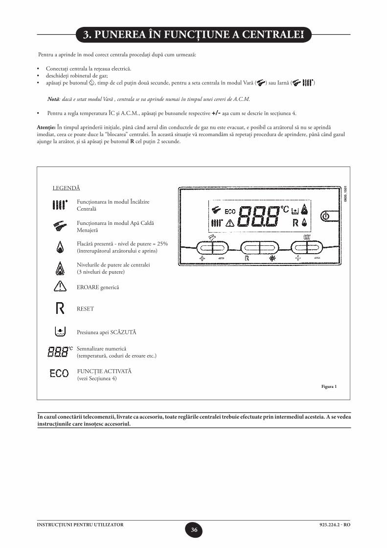
În cazul conectării telecomenzii, livrate ca accesoriu, toate reglările centralei trebuie efectuate prin intermediul acesteia. A se vedea instrucţiunile care însoţesc accesoriul.
3. punerea în funCţiune a Centralei
figura 1
Pentru a aprinde în mod corect centrala procedaţi după cum urmează:
• Conectaţicentralalareţeauaelectrică.• deschideţirobinetuldegaz;• apăsaţi pe butonul , timp de cel puţin două secunde, pentru a seta centrala în modul Vară ( ) sau Iarnă ( )
Notă: dacă e setat modul Vară , centrala se va aprinde numai în timpul unei cereri de A.C.M.
• PentruareglatemperaturaÎCşiA.C.M.,apăsaţipebutoanelerespective +/- aşa cum se descrie în secţiunea 4.
atenţie: În timpul aprinderii iniţiale, până când aerul din conductele de gaz nu este evacuat, e posibil ca arzătorul să nu se aprindă imediat, ceea ce poate duce la “blocarea” centralei. În această situaţie vă recomandăm să repetaţi procedura de aprindere, până când gazul ajunge la arzător, şi să apăsaţi pe butonul r cel puţin 2 secunde.
0605
_150
1LEGENDĂ
Funcţionarea în modul Încălzire Centrală
EROARE generică
Presiunea apei SCĂZUTĂ
Semnalizare numerică (temperatură, coduri de eroare etc.)
RESET
FUNCŢIE ACTIVATĂ (vezi Secţiunea 4)
Flacără prezentă - nivel de putere = 25% (întrerupătorul arzătorului e aprins)
Nivelurile de putere ale centralei (3 niveluri de putere)
Funcţionarea în modul Apă Caldă Menajeră
37925.224.2 - ROINSTRUCŢIUNI PENTRU UTILIZATOR
0605
_110
1
3.2 DESCRIEREA BUTONULUI (VARĂ - IARNĂ - NUMAI ÎNCĂLZIRE - STINS)
Prin apăsarea acestei taste se pot programa următoarele moduri de funcţionare a centralei:
• VARĂ• IARNĂ• NUMAI ÎNCĂLZIRE• OPRIT
În modul VARĂ pe afişaj apare simbolul ( ). pe afişaj apare simbolul (*). Centrala satisface doar necesităţile de apă caldă menajeră, încălzirea NU este activă (funcţia anti-îngheţ este activă).În modul IARNĂ pe afişaj apar simbolurile ( ) ( ). Centrala satisface atât necesităţile de apă caldă menajeră cât şi cele de încălzire (funcţia anti-îngheţ este activă).În modul NUMAI ÎNCĂLZIRE pe afişaj apare simbolul ( ). Centrala satisface doar necesităţile de încălzire (funcţia anti-îngheţ este activă).În cazul selectării modului OPRIT pe afişaj nu apare nici unul dintre simbolurile ( ) ( ). În această modalitate este activă doar funcţia anti-îngheţ în încăpere, orice solicitare de încălzire a apei menajere sau a încăperii nu va fi satisfăcută,
4. reglarea temperaturii din CirCuitul de înCălzire Centrală (îC) şi apă Caldă menajeră (a.C.m.)
Reglarea temperaturii pentru ÎC ( ) şi A.C.M. ( ) se efectuează apăsând pe butoanele corespunzătoare +/- (figura 1).Când arzătorul e aprins, pe afişaj apare simbolul ( ).
înCălzire Centrală (îC)Instalaţia trebuie să fie dotată cu un termostat de cameră (vezi reglementările respective) pentru a controla temperatura din încăperi. În timpul funcţionării în modul ÎC, pe afişaj apare un simbol ÎC ( ), care clipeşte intermitent, şi valoarea temperaturii în tur pentru ÎC (°C).
apă Caldă menajeră (a.C.m.)În timpul unei cereri de A.C.M., pe afişaj apare simbolul pentru A.C.M. ( ), care clipeşte intermitent, şi valoarea temperaturii în tur pentru A.C.M. (°C).
Există două temperaturi programate (setpoint) care pot fi setate rapid: eCo şi Comfort.
eCoTemperatura programată (setpoint) ECO permite utilizatorului să programeze rapid respectiva temperatură pentru apa caldă menajeră, apăsând pe buton P. În modul de funcţionare eco pe afişaj apare mesajul “eco”. Pentru a seta temperatura programată (setpoint) ECO apăsaţi pe butoanele +/- .
ComfortTemperatura programată (setpoint) COMFORT permite utilizatorului să programeze rapid respectiva temperatură pentru apa caldă menajeră, apăsând pe buton . Pentru a seta temperatura programată (setpoint) COMFORT apăsaţi pe butoanele +/- .
Atenţie: funcţia e activă doar dacă parametrul PM12=0, aşa cum se descrie în secţiunea 20 (valoare implicită).
NOTĂ: în cazul racordării unui boiler, în timpul funcţionării centralei în modul apă caldă menajeră, pe afişaj apare simbolul ( ) şi temperatura camerei (°C).
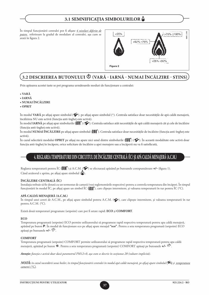
În timpul funcţionării centralei pot fi afişate 4 niveluri diferite de putere referitoare la gradul de modulare al centralei, aşa cum se arată în figura 2.
3.1 semnifiCaţia simbolurilor
Figura 2
38925.224.2 - ROINSTRUCŢIUNI PENTRU UTILIZATOR
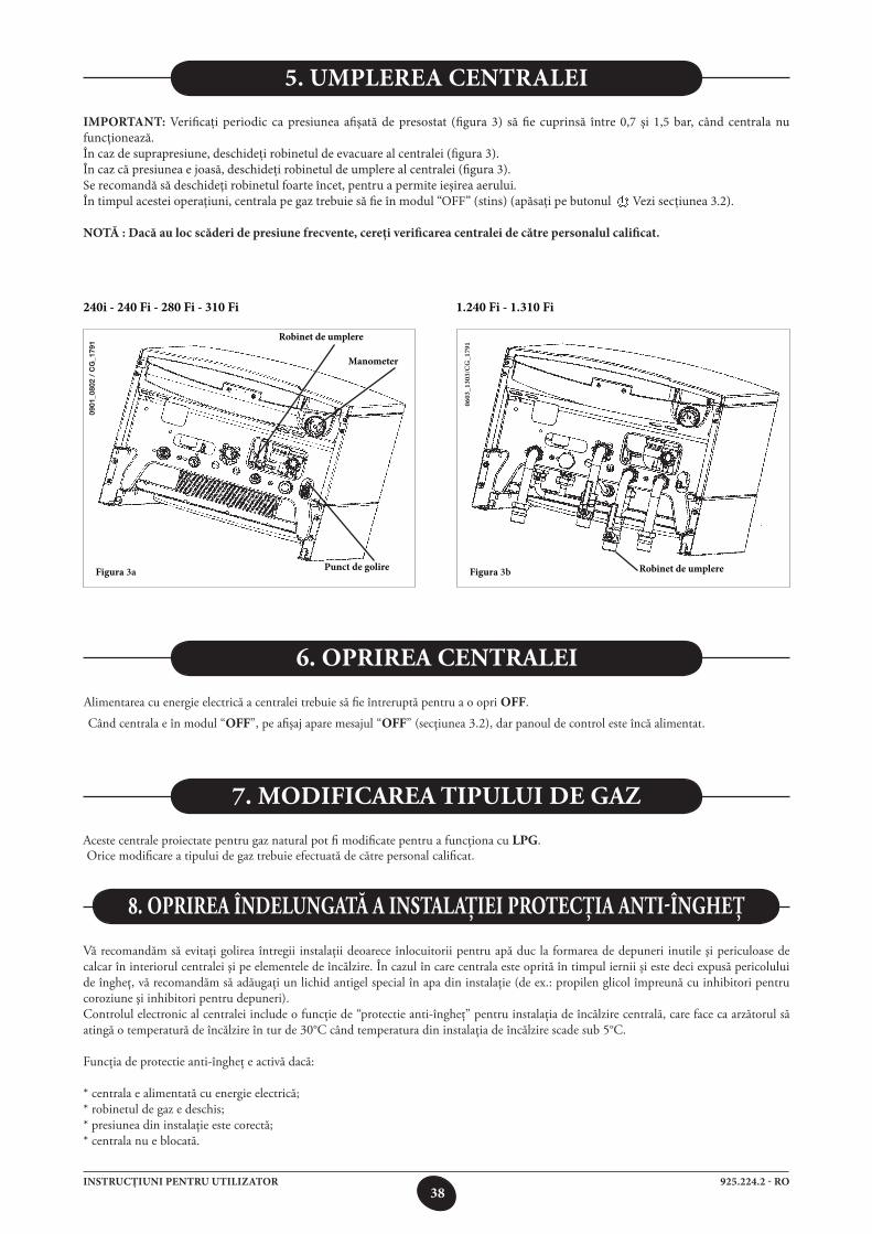
IMPORTANT: Verificaţi periodic ca presiunea afişată de presostat (figura 3) să fie cuprinsă între 0,7 şi 1,5 bar, când centrala nu funcţionează.În caz de suprapresiune, deschideţi robinetul de evacuare al centralei (figura 3).În caz că presiunea e joasă, deschideţi robinetul de umplere al centralei (figura 3).Se recomandă să deschideţi robinetul foarte încet, pentru a permite ieşirea aerului.În timpul acestei operaţiuni, centrala pe gaz trebuie să fie în modul “OFF” (stins) (apăsaţi pe butonul Vezi secţiunea 3.2).
NOTĂ : Dacă au loc scăderi de presiune frecvente, cereţi verificarea centralei de către personalul calificat.
5. UMPLEREA CENTRALEI
Figura 3a
Robinet de umplere
Punct de golire
Manometer
Figura 3b
0603
_130
3/C
G_1
791
240i - 240 Fi - 280 Fi - 310 Fi 1.240 Fi - 1.310 Fi
Robinet de umplere
Alimentarea cu energie electrică a centralei trebuie să fie întreruptă pentru a o opri off.
Când centrala e în modul “off”, pe afişaj apare mesajul “off” (secţiunea 3.2), dar panoul de control este încă alimentat.
6. oprirea Centralei
7. modifiCarea tipului de gaz
Aceste centrale proiectate pentru gaz natural pot fi modificate pentru a funcţiona cu lpg. Orice modificare a tipului de gaz trebuie efectuată de către personal calificat.
Vă recomandăm să evitaţi golirea întregii instalaţii deoarece înlocuitorii pentru apă duc la formarea de depuneri inutile şi periculoase de calcar în interiorul centralei şi pe elementele de încălzire. În cazul în care centrala este oprită în timpul iernii şi este deci expusă pericolului de îngheţ, vă recomandăm să adăugaţi un lichid antigel special în apa din instalaţie (de ex.: propilen glicol împreună cu inhibitori pentru coroziune şi inhibitori pentru depuneri).Controlul electronic al centralei include o funcţie de “protectie anti-îngheţ” pentru instalaţia de încălzire centrală, care face ca arzătorul să atingă o temperatură de încălzire în tur de 30°C când temperatura din instalaţia de încălzire scade sub 5°C.
Funcţia de protectie anti-îngheţ e activă dacă:
* centrala e alimentată cu energie electrică;* robinetul de gaz e deschis;* presiunea din instalaţie este corectă;* centrala nu e blocată.
8. oprirea îndelungată a instalaţiei proteCţia anti-îngheţ
0901
_080
2 /
CG
_179
1
39925.224.2 - ROINSTRUCŢIUNI PENTRU UTILIZATOR
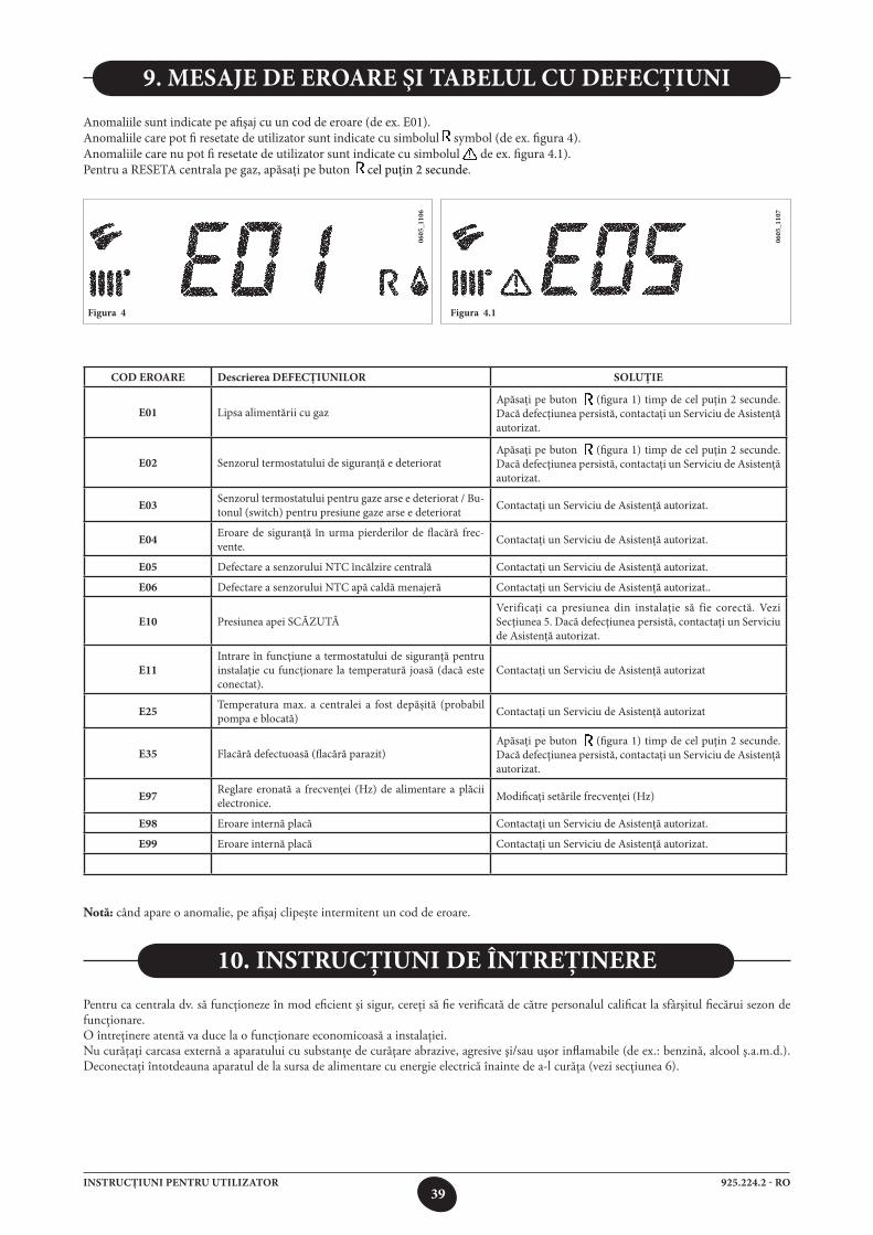
9. MESAJE DE EROARE ŞI TABELUL CU DEFECŢIUNI
COD EROARE Descrierea DEFECŢIUNILOR SOLUŢIE
E01 Lipsa alimentării cu gazApăsaţi pe buton (figura 1) timp de cel puţin 2 secunde. Dacă defecţiunea persistă, contactaţi un Serviciu de Asistenţă autorizat.
E02 Senzorul termostatului de siguranţă e deterioratApăsaţi pe buton (figura 1) timp de cel puţin 2 secunde. Dacă defecţiunea persistă, contactaţi un Serviciu de Asistenţă autorizat.
E03 Senzorul termostatului pentru gaze arse e deteriorat / Bu-tonul (switch) pentru presiune gaze arse e deteriorat Contactaţi un Serviciu de Asistenţă autorizat.
E04 Eroare de siguranţă în urma pierderilor de flacără frec- vente. Contactaţi un Serviciu de Asistenţă autorizat.
E05 Defectare a senzorului NTC încălzire centrală Contactaţi un Serviciu de Asistenţă autorizat.
E06 Defectare a senzorului NTC apă caldă menajeră Contactaţi un Serviciu de Asistenţă autorizat..
E10 Presiunea apei SCĂZUTĂVerificaţi ca presiunea din instalaţie să fie corectă. Vezi Secţiunea 5. Dacă defecţiunea persistă, contactaţi un Serviciu de Asistenţă autorizat.
E11Intrare în funcţiune a termostatului de siguranţă pentru instalaţie cu funcţionare la temperatură joasă (dacă este conectat).
Contactaţi un Serviciu de Asistenţă autorizat
E25 Temperatura max. a centralei a fost depăşită (probabil pompa e blocată) Contactaţi un Serviciu de Asistenţă autorizat
E35 Flacără defectuoasă (flacără parazit)Apăsaţi pe buton (figura 1) timp de cel puţin 2 secunde. Dacă defecţiunea persistă, contactaţi un Serviciu de Asistenţă autorizat.
E97 Reglare eronată a frecvenţei (Hz) de alimentare a plăcii electronice. Modificaţi setările frecvenţei (Hz)
E98 Eroare internă placă Contactaţi un Serviciu de Asistenţă autorizat.
E99 Eroare internă placă Contactaţi un Serviciu de Asistenţă autorizat.
Figura 4
0605
_110
6
Anomaliile sunt indicate pe afişaj cu un cod de eroare (de ex. E01).Anomaliile care pot fi resetate de utilizator sunt indicate cu simbolul symbol (de ex. figura 4).Anomaliile care nu pot fi resetate de utilizator sunt indicate cu simbolul de ex. figura 4.1). Pentru a RESETA centrala pe gaz, apăsaţi pe buton cel puţin 2 secunde.
Figura 4.1
0605
_110
7
Pentru ca centrala dv. să funcţioneze în mod eficient şi sigur, cereţi să fie verificată de către personalul calificat la sfârşitul fiecărui sezon de funcţionare.O întreţinere atentă va duce la o funcţionare economicoasă a instalaţiei.Nu curăţaţi carcasa externă a aparatului cu substanţe de curăţare abrazive, agresive şi/sau uşor inflamabile (de ex.: benzină, alcool ş.a.m.d.). Deconectaţi întotdeauna aparatul de la sursa de alimentare cu energie electrică înainte de a-l curăţa (vezi secţiunea 6).
10. instruCţiuni de întreţinere
notă: când apare o anomalie, pe afişaj clipeşte intermitent un cod de eroare.
40925.224.2 - ROINSTRUCŢIUNI PENTRU INSTALATOR
Această centrală este destinată încălzirii apei la o temperatură inferioară celei de fierbere la presiune atmosferică. Centrala trebuie să fie racordată la o instalaţie de încălzire centrală şi la o instalaţie pentru apă caldă menajeră, în conformitate cu performanţele sale şi cu puterea de ieşire.Centrala trebuie să fie instalată de Personal Calificat şi trebuie să se efectueze următoarele operaţii:
a) să se verifice cu grijă că centrala este adecvată pentru funcţionarea cu tipul de gaz disponibil. Pentru informaţii mai detaliate vezi indicaţiile de pe ambalaj şi eticheta de pe aparat.
b) să se verifice cu grijă că tirajul coşului pentru gaze arse este adecvat; că hornul nu este blocat şi că prin acelaşi coş de evacuare nu sunt evacuate şi gazele arse care provin de la alte aparate, în afară de cazul în care coşul este proiectat în mod special pentru a colecta gazele arse de la mai multe aparate, conform legilor şi reglementărilor în vigoare.
c) să se verifice cu grijă, în cazul racordării hornului la hornuri preexistente, că acestea au fost curăţate perfect, întrucât produsele reziduale de ardere se pot desprinde de pe pereţi în timpul funcţionării centralei şi pot bloca hornul.
Pentru a asigura funcţionarea corectă a aparatului şi pentru a evita anularea garanţiei, respectaţi următoarele măsuri de precauţie:
1. Circuitul pentru apă caldă:
1.1. Dacă duritatea apei e mai mare de 20 °F (1 °F = 10 mg de carbonat de calciu la un litru de apă) se recomandă instalarea unui sistem de tratament cu polifosfaţi sau a unui sistem cu efect similar, în conformitate cu normele în vigoare.
1.2. Circuitul de apă caldă menajeră trebuie să fie golit complet după instalarea aparatului şi înainte de utilizarea sa.
1.3. Materialele utilizate pentru circuitul de apă menajeră sunt conforme cu Directiva 98/83/CE.
2. Circuitul de încălzire
2.1. instalaţie nouă Înainte de a trece la instalarea centralei, instalaţia trebuie curăţată şi golită în mod corespunzător, pentru a elimina bavurile rămase
în urma sudurii, zgura şi eventualii solvenţi, folosind produse speciale adecvate. Pentru a evita deteriorarea pieselor din metal, plastic şi cauciuc, folosiţi numai substanţe de curăţare neutre, adică neacide şi nealcaline.
Produsele recomandate pentru curăţare sunt: SENTINEL X300 sau X400 şi FERNOX Regenerator pentru instalaţiile de încălzire. Pentru a utiliza acest produs urmaţi cu stricteţe
instrucţiunile producătorului.
2.2. instalaţie existentă Înainte de a trece la instalarea centralei, instalaţia trebuie curăţată şi golită pentru a îndepărta depunerile de noroi şi substanţele
contaminante, folosind produse speciale adecvate, aşa cum se indică în secţiunea 2.1. Pentru a evita deteriorarea pieselor din metal, plastic şi cauciuc, folosiţi numai substanţe de curăţare neutre, adică neacide şi nealcaline,
precum SENTINEL X100 şi FERNOX protector pentru instalaţiile de încălzire. Pentru a utiliza acest produs urmaţi cu stricteţe instrucţiunile producătorului.
Reţineţi că prezenţa materiilor străine în circuitul de încălzire poate afecta funcţionarea centralei (de ex. supraîncălzire şi funcţionarea zgomotoasă a schimbătorului de căldură).
nerespectarea recomandărilor de mai sus va duce la anularea garanţiei.
12. instruCţiuni înainte de instalare
Următoarele recomandări şi instrucţiuni se adresează tehnicienilor specialişti pentru a-i ajuta să efectueze o instalare corectă. Instrucţiunile privind aprinderea şi funcţionarea centralei se găsesc în secţiunea ‘Instrucţiuni pentru utilizator’.Reţineţi că instalarea, întreţinerea şi punerea în funcţiune a aparatelor electrocasnice cu gaz trebuie efectuate numai de către personal calificat, în conformitate cu standardele curente.Atenţie:* Această centrală poate fi racordată la orice fel de convector cu alimentare prin tuburi duble sau simple, radiatoare, termoconvectoare.
Proiectaţi secţiunile instalaţiei ca de obicei, luând însă în considerare performanţele disponibile debit / înălţime de pompare, aşa cum se indică în secţiunea 24.
* Nu lăsaţi la îndemâna copiilor materialele de ambalaj (saci de plastic, polistiren etc.) deoarece reprezintă o potenţială sursă de pericol.* Prima aprindere a centralei trebuie să fie efectuată de personal calificat. Nerespectarea recomandărilor de mai sus va duce la anularea garanţiei.
11. informaţii generale
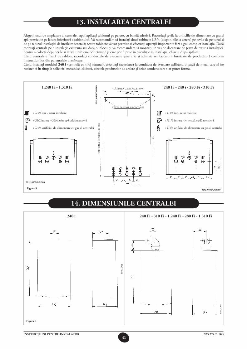
41925.224.2 - ROINSTRUCŢIUNI PENTRU INSTALATOR
240 i 240 Fi - 310 Fi - 1.240 Fi - 280 Fi - 1.310 Fi
240 Fi - 240 i - 280 Fi - 310 Fi 1.240 Fi - 1.310 Fi
13. instalarea Centralei
Alegeţi locul de amplasare al centralei, apoi aplicaţi şablonul pe perete, cu bandă adezivă. Racordaţi ţevile la orificiile de alimentare cu gaz şi apă prevăzute pe latura inferioară a şablonului. Vă recomandăm să instalaţi două robinete G3/4 (disponibile la cerere) pe ţevile de pe turul şi de pe returul instalaţiei de încălzire centrală; aceste robinete vă vor permite să efectuaţi operaţii importante fără a goli complet instalaţia. Dacă montaţi centrala pe o instalaţie existentă sau dacă o înlocuiţi, vă recomandăm să montaţi un vas de decantare pe ţeava de retur a instalaţiei, pentru a colecta depunerile şi reziduurile care pot rămâne şi care pot fi puse în circulaţie în instalaţie, chiar şi după spălare.Când centrala e fixată pe şablon, racordaţi conductele de evacuare gaze arse şi admisie aer (accesorii furnizate de producător) conform instrucţiunilor din paragrafele următoare.Când instalaţi modelul 240 i (centrală cu tiraj natural), efectuaţi racordarea la conducta de evacuare utilizând o ţeavă de metal care să fie rezistentă în timp la solicitări mecanice, căldură, efectele produselor de ardere şi orice condens care s-ar putea forma.
figura 5
14. dimensiunile Centralei
figura 6
0701
_170
1
0701
_170
2
min
im
= LĂŢIMEA CENTRALEI 450 =
PUNCTE DE FIXARE ALE CENTRALEI
ÎNĂL
ŢIM
EA C
ENT
RAL
EI 7
80
: G3/4 tur - retur încălzire
: G1/2 intrare - ieşire apă caldă menajeră
: G3/4 orificiul de alimentare cu gaz al centralei
0512
_050
4/C
G17
69
0512_0505/CG1769
0512_0503/CG1769
: G3/4 tur - retur încălzire
: G1/2 intrare - G3/4 ieşire apă caldă menajeră
: G3/4 orificiul de alimentare cu gaz al centralei
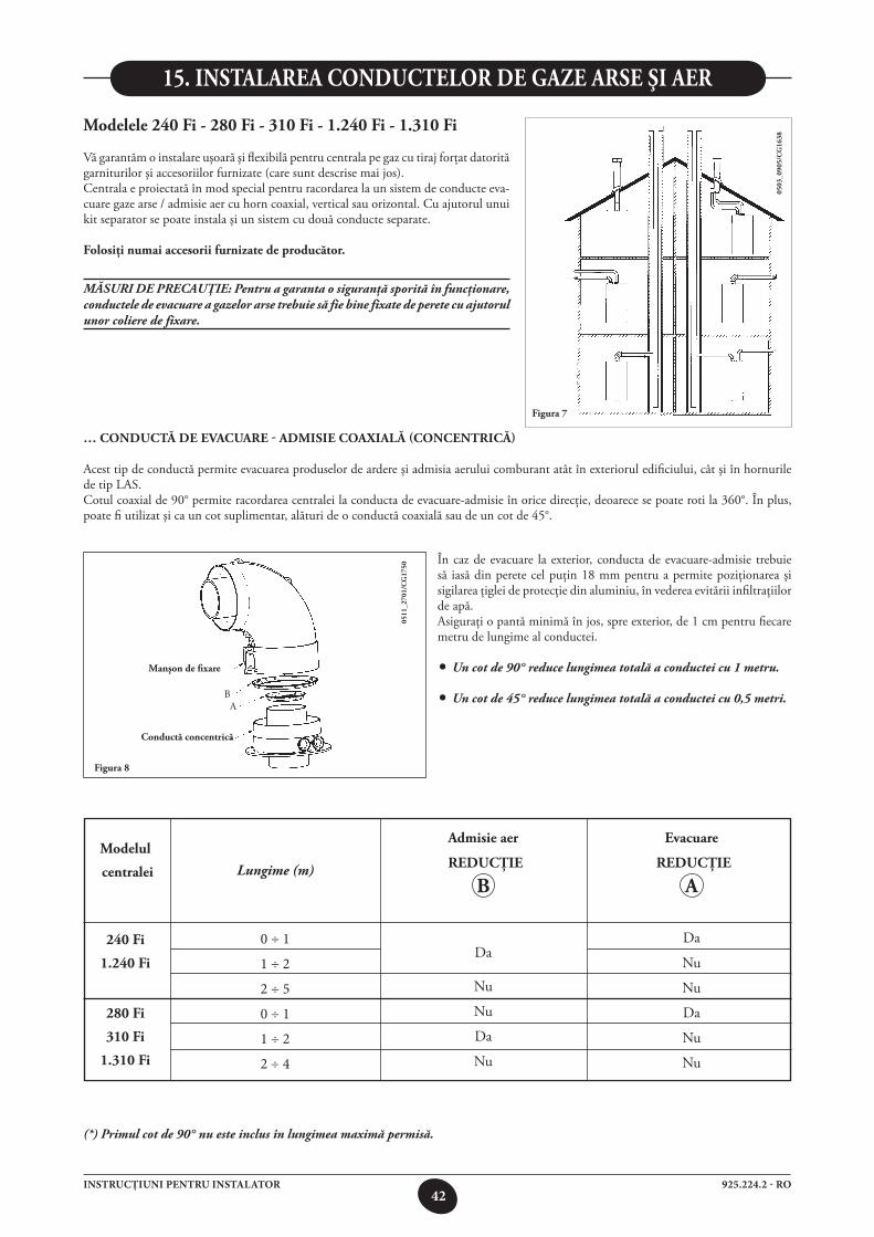
42925.224.2 - ROINSTRUCŢIUNI PENTRU INSTALATOR
0 ÷ 1
1 ÷ 2
2 ÷ 5
0 ÷ 1
1 ÷ 2
2 ÷ 4
15. instalarea ConduCtelor de gaze arse şi aer
modelele 240 fi - 280 fi - 310 fi - 1.240 fi - 1.310 fi
Vă garantăm o instalare uşoară şi flexibilă pentru centrala pe gaz cu tiraj forţat datorită garniturilor şi accesoriilor furnizate (care sunt descrise mai jos).Centrala e proiectată în mod special pentru racordarea la un sistem de conducte eva-cuare gaze arse / admisie aer cu horn coaxial, vertical sau orizontal. Cu ajutorul unui kit separator se poate instala şi un sistem cu două conducte separate.
folosiţi numai accesorii furnizate de producător.
MĂSURI DE PRECAUŢIE: Pentru a garanta o siguranţă sporită în funcţionare, conductele de evacuare a gazelor arse trebuie să fie bine fixate de perete cu ajutorul unor coliere de fixare.
figura 7
0503
_090
5/C
g16
38figura 8
… ConduCtă de evaCuare - admisie Coaxială (ConCentriCă)
Acest tip de conductă permite evacuarea produselor de ardere şi admisia aerului comburant atât în exteriorul edificiului, cât şi în hornurile de tip LAS.Cotul coaxial de 90° permite racordarea centralei la conducta de evacuare-admisie în orice direcţie, deoarece se poate roti la 360°. În plus, poate fi utilizat şi ca un cot suplimentar, alături de o conductă coaxială sau de un cot de 45°.
0511
_270
1/C
g17
50
În caz de evacuare la exterior, conducta de evacuare-admisie trebuie să iasă din perete cel puţin 18 mm pentru a permite poziţionarea şi sigilarea ţiglei de protecţie din aluminiu, în vederea evitării infiltraţiilor de apă.Asiguraţi o pantă minimă în jos, spre exterior, de 1 cm pentru fiecare metru de lungime al conductei.
• Un cot de 90° reduce lungimea totală a conductei cu 1 metru.
• Un cot de 45° reduce lungimea totală a conductei cu 0,5 metri.
manşon de fixare
Conductă concentrică
AB
(*) Primul cot de 90° nu este inclus în lungimea maximă permisă.
modelul
centralei
240 fi
1.240 fi
280 fi
310 fi
1.310 fi
Lungime (m)
admisie aer
reduCţie
b
Da
Nu
Nu
Da
Nu
evacuare
reduCţie
a
Da
Nu
Nu
Da
Nu
Nu
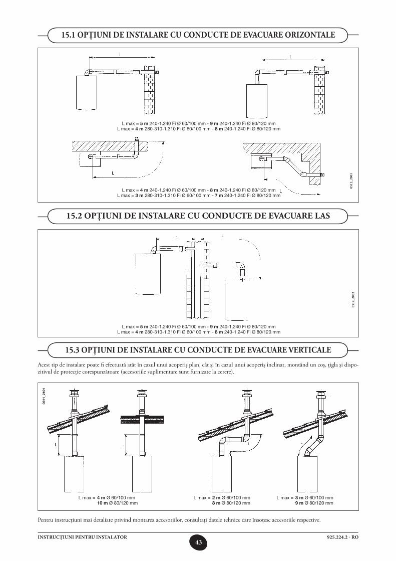
43925.224.2 - ROINSTRUCŢIUNI PENTRU INSTALATOR
15.1 opţiuni de instalare Cu ConduCte de evaCuare orizontale
15.2 opţiuni de instalare Cu ConduCte de evaCuare las
15.3 opţiuni de instalare Cu ConduCte de evaCuare vertiCale
Acest tip de instalare poate fi efectuată atât în cazul unui acoperiş plan, cât şi în cazul unui acoperiş înclinat, montând un coş, ţigla şi dispo-zitivul de protecţie corespunzătoare (accesoriile suplimentare sunt furnizate la cerere).
0512
_200
1 05
12_2
002
Pentru instrucţiuni mai detaliate privind montarea accesoriilor, consultaţi datele tehnice care însoţesc accesoriile respective.
0611
_210
1
L max = 2 m Ø 60/100 mm 8 m Ø 80/120 mm
L max = 4 m Ø 60/100 mm 10 m Ø 80/120 mm
L max = 3 m Ø 60/100 mm 9 m Ø 80/120 mm
L max = 5 m 240-1.240 Fi Ø 60/100 mm - 9 m 240-1.240 Fi Ø 80/120 mmL max = 4 m 280-310-1.310 Fi Ø 60/100 mm - 8 m 240-1.240 Fi Ø 80/120 mm
L max = 4 m 240-1.240 Fi Ø 60/100 mm - 8 m 240-1.240 Fi Ø 80/120 mmL max = 3 m 280-310-1.310 Fi Ø 60/100 mm - 7 m 240-1.240 Fi Ø 80/120 mm
L max = 5 m 240-1.240 Fi Ø 60/100 mm - 9 m 240-1.240 Fi Ø 80/120 mmL max = 4 m 280-310-1.310 Fi Ø 60/100 mm - 8 m 240-1.240 Fi Ø 80/120 mm
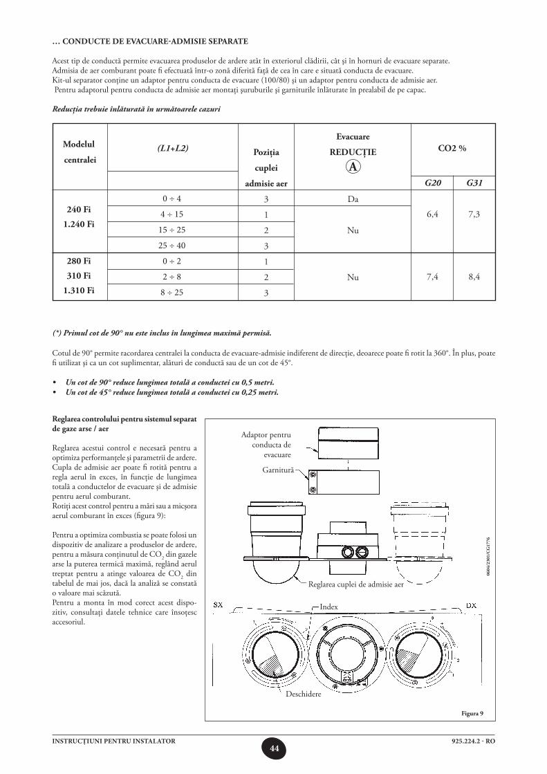
44925.224.2 - ROINSTRUCŢIUNI PENTRU INSTALATOR
0 ÷ 4
4 ÷ 15
15 ÷ 25
25 ÷ 40
0 ÷ 2
2 ÷ 8
8 ÷ 25
… ConduCte de evaCuare-admisie separate
Acest tip de conductă permite evacuarea produselor de ardere atât în exteriorul clădirii, cât şi în hornuri de evacuare separate.Admisia de aer comburant poate fi efectuată într-o zonă diferită faţă de cea în care e situată conducta de evacuare.Kit-ul separator conţine un adaptor pentru conducta de evacuare (100/80) şi un adaptor pentru conducta de admisie aer. Pentru adaptorul pentru conducta de admisie aer montaţi şuruburile şi garniturile înlăturate în prealabil de pe capac.
Reducţia trebuie înlăturată în următoarele cazuri
figura 9
Cotul de 90° permite racordarea centralei la conducta de evacuare-admisie indiferent de direcţie, deoarece poate fi rotit la 360°. În plus, poate fi utilizat şi ca un cot suplimentar, alături de conductă sau de un cot de 45°.
• Un cot de 90° reduce lungimea totală a conductei cu 0,5 metri.• Un cot de 45° reduce lungimea totală a conductei cu 0,25 metri.
0604
/230
1/C
g17
76
(*) Primul cot de 90° nu este inclus în lungimea maximă permisă.
reglarea controlului pentru sistemul separat de gaze arse / aer
Reglarea acestui control e necesară pentru a optimiza performanţele şi parametrii de ardere. Cupla de admisie aer poate fi rotită pentru a regla aerul în exces, în funcţie de lungimea totală a conductelor de evacuare şi de admisie pentru aerul comburant.Rotiţi acest control pentru a mări sau a micşora aerul comburant în exces (figura 9):
Pentru a optimiza combustia se poate folosi un dispozitiv de analizare a produselor de ardere, pentru a măsura conţinutul de CO2 din gazele arse la puterea termică maximă, reglând aerul treptat pentru a atinge valoarea de CO2 din tabelul de mai jos, dacă la analiză se constată o valoare mai scăzută.Pentru a monta în mod corect acest dispo-zitiv, consultaţi datele tehnice care însoţesc accesoriul.
Adaptor pentru conducta de
evacuare
Garnitură
Reglarea cuplei de admisie aer
Index
Deschidere
modelul
centralei
240 fi
1.240 fi
280 fi
310 fi
1.310 fi
(L1+L2) poziţia
cuplei
admisie aer
3
1
2
3
1
2
3
evacuare
reduCţie
a
Da
Nu
Nu
Co2 %
G20
6,4
7,4
G31
7,3
8,4
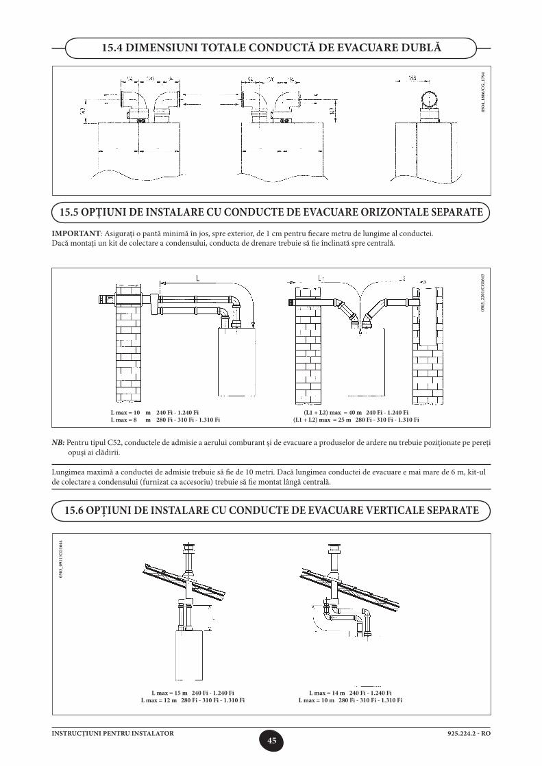
45925.224.2 - ROINSTRUCŢIUNI PENTRU INSTALATOR
0503
_220
1/C
G16
43
15.5 OPŢIUNI DE INSTALARE CU CONDUCTE DE EVACUARE ORIZONTALE SEPARATE
IMPORTANT: Asiguraţi o pantă minimă în jos, spre exterior, de 1 cm pentru fiecare metru de lungime al conductei. Dacă montaţi un kit de colectare a condensului, conducta de drenare trebuie să fie înclinată spre centrală.
NB: Pentru tipul C52, conductele de admisie a aerului comburant şi de evacuare a produselor de ardere nu trebuie poziţionate pe pereţi opuşi ai clădirii.
Lungimea maximă a conductei de admisie trebuie să fie de 10 metri. Dacă lungimea conductei de evacuare e mai mare de 6 m, kit-ul de colectare a condensului (furnizat ca accesoriu) trebuie să fie montat lângă centrală.
15.4 DIMENSIUNI TOTALE CONDUCTĂ DE EVACUARE DUBLĂ
0504
_180
6/C
G_1
794
0503
_091
1/C
G16
44
15.6 OPŢIUNI DE INSTALARE CU CONDUCTE DE EVACUARE VERTICALE SEPARATE
(L1 + L2) max = 40 m 240 Fi - 1.240 Fi(L1 + L2) max = 25 m 280 Fi - 310 Fi - 1.310 Fi
L max = 10 m 240 Fi - 1.240 FiL max = 8 m 280 Fi - 310 Fi - 1.310 Fi
L max = 15 m 240 Fi - 1.240 FiL max = 12 m 280 Fi - 310 Fi - 1.310 Fi
L max = 14 m 240 Fi - 1.240 Fi L max = 10 m 280 Fi - 310 Fi - 1.310 Fi
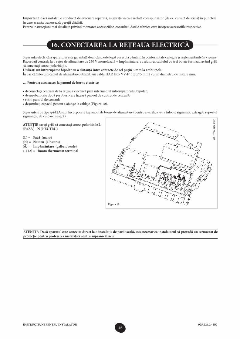
46925.224.2 - ROINSTRUCŢIUNI PENTRU INSTALATOR
16. CONECTAREA LA REŢEAUA ELECTRICĂ
Siguranţa electrică a aparatului este garantată doar când este legat corect la pământ, în conformitate cu legile şi reglementările în vigoare. Racordaţi centrala la o reţea de alimentare de 230 V monofazată + împământare, cu ajutorul cablului cu trei borne furnizat, având grijă să conectaţi corect polarităţile.Utilizaţi un întrerupător bipolar cu o distanţă între contacte de cel puţin 3 mm la ambii poli.În caz că înlocuiţi cablul de alimentare, utilizaţi un cablu HAR H05 VV-F’ 3 x 0,75 mm2 cu un diametru de max. 8 mm.
… Pentru a avea acces la panoul de borne electrice
• deconectaţi centrala de la reţeaua electrică prin intermediul întrerupătorului bipolar;• deşurubaţi cele două şuruburi care fixează panoul de control de centrală;• rotiţi panoul de control;• deşurubaţi capacul pentru a ajunge la cablaje (Figura 10).
Siguranţele de tip rapid 2A sunt încorporate în panoul de borne de alimentare (pentru a verifica sau a înlocui siguranţa, extrageţi suportul
Figura 10
siguranţei, de culoare neagră).
ATENŢIE : aveţi grijă să conectaţi corect polarităţile L (FAZĂ) - N (NEUTRU).
(L) = Fază (maro)(N) = Neutru (albastru) = Împământare (galben/verde)(1) (2) = Room thermostat terminal
Important: dacă instalaţi o conductă de evacuare separată, asiguraţi-vă că e izolată corespunzător (de ex. cu vată de sticlă) în puncteleîn care aceasta traversează pereţii clădirii.Pentru instrucţiuni mai detaliate privind montarea accesoriilor, consultaţi datele tehnice care însoţesc accesoriile respective.
ATENŢIE: Dacă aparatul este conectat direct la o instalaţie de pardoseală, este necesar ca instalatorul să prevadă un termostat de protecţie pentru protejarea instalaţiei contra supraîncălzirii.
CG
_177
0 /
0904
_070
7
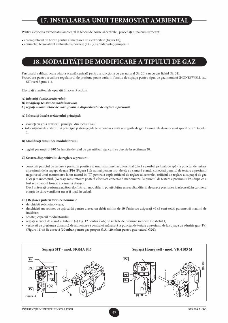
47925.224.2 - ROINSTRUCŢIUNI PENTRU INSTALATOR
Personalul calificat poate adapta această centrală pentru a funcţiona cu gaz natural (G. 20) sau cu gaz lichid (G. 31).Procedura pentru a calibra regulatorul de presiune poate varia în funcţie de supapa pentru tipul de gaz montată (HONEYWELL sau
SIT; vezi figura 11).
Efectuaţi următoarele operaţii în această ordine: A) înlocuiţi duzele arzătorului;B) modificaţi tensiunea modulatorului;C) reglaţi o nouă setare de max. şi min. a dispozitivului de reglare a presiunii.
A) Înlocuiţi duzele arzătorului principal;
• scoateţi cu grijă arzătorul principal din locaşul său;• înlocuiţi duzele arzătorului principal şi strângeţi-le bine pentru a evita scurgerile de gaz. Diametrele duzelor sunt specificate în tabelul
1.
B) Modificaţi tensiunea modulatorului
• reglaţi parametrul F02 în funcţie de tipul de gaz utilizat, aşa cum se descrie în secţiunea 20.
C) Setarea dispozitivului de reglare a presiunii • conectaţi punctul de testare a presiunii pozitive al unui manometru diferenţial (dacă e posibil, pe bază de apă) la punctul de testare
a presiunii de la supapa de gaz (Pb) (Figura 11); numai pentru mo- delele cu cameră etanşă: conectaţi punctul de testare a presiunii negative al unui manometru la un racord în “T” pentru a cupla orificiul de reglare al centralei, orificiul de reglare al supapei de gaz (Pc) şi manometrul. (Aceeaşi măsurătoare poate fi efectuată conectând manometrul la punctul de testare a presiunii (Pb) după ce a fost scos panoul frontal al camerei etanşe);
Dacă măsuraţi presiunea arzătoarelor într-un mod diferit, puteţi obţine un rezultat diferit, deoarece presiunea joasă creată în ca- mera etanşă de către ventilator nu ar fi luată în calcul.
C1) Reglarea puterii termice nominale• deschideţi robinetul de gaz;• deschideţi un robinet de apă caldă pentru a avea un debit minim de 10 l/min sau asiguraţi-vă că sunt setaţi parametrii maximi de
încălzire;• scoateţi capacul modulatorului;• reglaţi şurubul de alamă al tubului (a) Fig. 12 pentru a obţine setările de presiune indicate în tabelul 1;• verificaţi ca presiunea dinamică de alimentare a centralei, măsurată la punctul de testare a presiunii de la supapa de admisie gaz (Pa)
(Figura 11) să fie corectă (30 mbar pentru gaz propan G.31, 20 mbar pentru gaz natural G20);
18. MODALITĂŢI DE MODIFICARE A TIPULUI DE GAZ
Figura 11
17. INSTALAREA UNUI TERMOSTAT AMBIENTAL
Pentru a conecta termostatul ambiental la blocul de borne al centralei, procedaţi după cum urmează:
• accesaţi blocul de borne pentru alimentarea cu electricitate (figura 10);• connectaţi termostatul ambiental la bornele (1) - (2) şi îndepărtaţi jumper-ul.
Supapă SIT - mod. SIGMA 845 Supapă Honeywell - mod. VK 4105 M
0904
_070
1
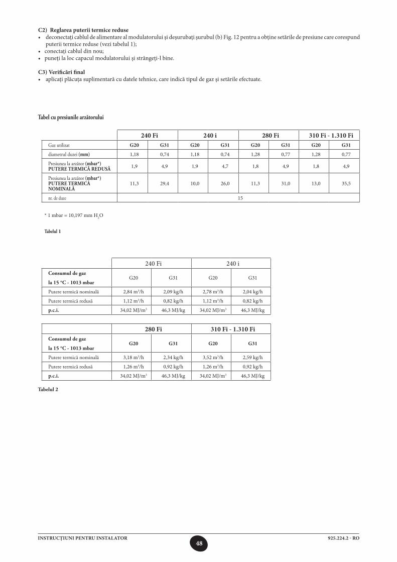
48925.224.2 - ROINSTRUCŢIUNI PENTRU INSTALATOR
C2) Reglarea puterii termice reduse• deconectaţi cablul de alimentare al modulatorului şi deşurubaţi şurubul (b) Fig. 12 pentru a obţine setările de presiune care corespund
puterii termice reduse (vezi tabelul 1);• conectaţi cablul din nou;• puneţi la loc capacul modulatorului şi strângeţi-l bine.
C3) Verificări final• aplicaţi plăcuţa suplimentară cu datele tehnice, care indică tipul de gaz şi setările efectuate.
tabel cu presiunile arzătorului
240 Fi 240 i 280 Fi 310 Fi - 1.310 FiGaz utilizat G20 G31 G20 G31 G20 G31 G20 G31
diametrul duzei (mm) 1,18 0,74 1,18 0,74 1,28 0,77 1,28 0,77
Presiunea la arzător (mbar*) putere termiCă redusă 1,9 4,9 1,9 4,7 1,8 4,9 1,8 4,9
Presiunea la arzător (mbar*) putere termiCă nominală
11,3 29,4 10,0 26,0 11,3 31,0 13,0 35,5
nr. de duze 15
* 1 mbar = 10,197 mm H2O
tabelul 1
240 Fi 240 iConsumul de gaz
la 15 °C - 1013 mbarG20 G31 G20 G31
Putere termică nominală 2,84 m3/h 2,09 kg/h 2,78 m3/h 2,04 kg/h
Putere termică redusă 1,12 m3/h 0,82 kg/h 1,12 m3/h 0,82 kg/h
p.c.i. 34,02 MJ/m3 46,3 MJ/kg 34,02 MJ/m3 46,3 MJ/kg
280 Fi 310 Fi - 1.310 FiConsumul de gaz
la 15 °C - 1013 mbarG20 G31 G20 G31
Putere termică nominală 3,18 m3/h 2,34 kg/h 3,52 m3/h 2,59 kg/h
Putere termică redusă 1,26 m3/h 0,92 kg/h 1,26 m3/h 0,92 kg/h
p.c.i. 34,02 MJ/m3 46,3 MJ/kg 34,02 MJ/m3 46,3 MJ/kg
tabelul 2
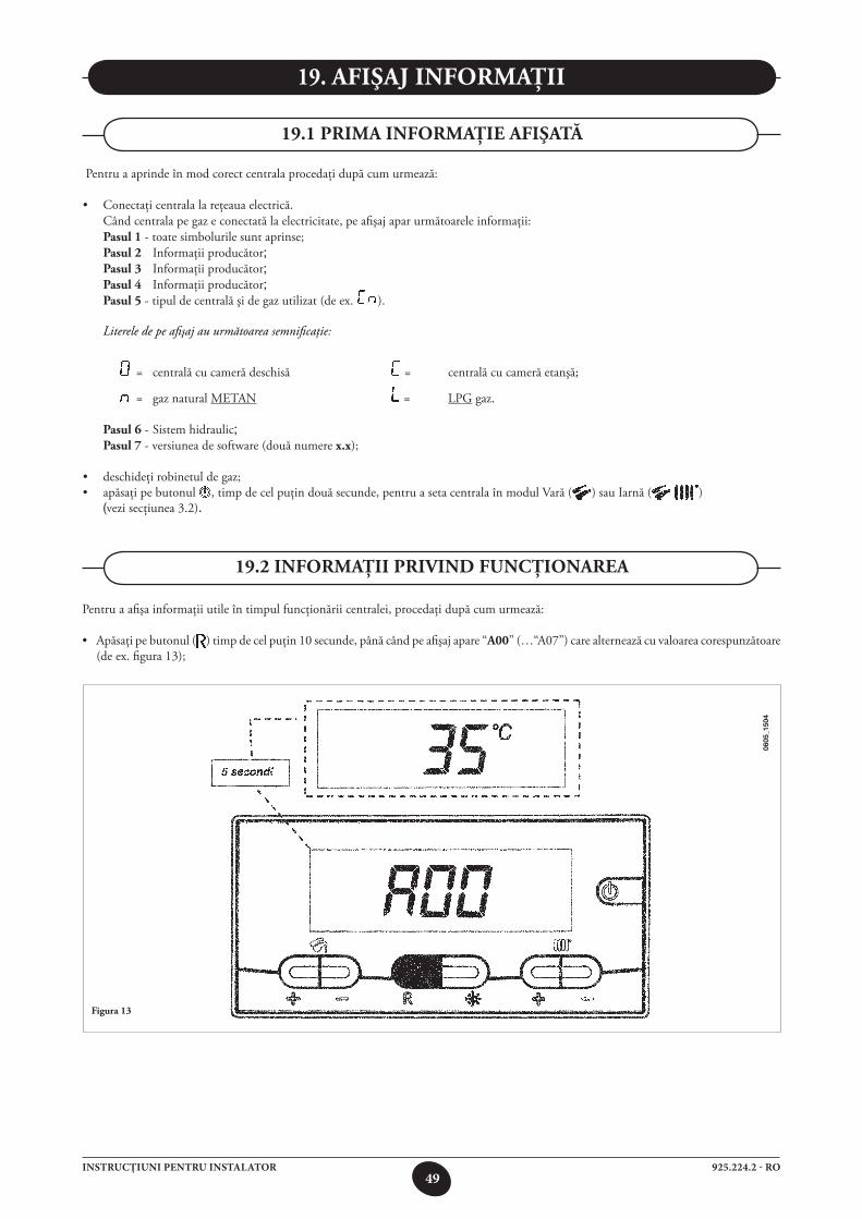
49925.224.2 - ROINSTRUCŢIUNI PENTRU INSTALATOR
Pentru a afişa informaţii utile în timpul funcţionării centralei, procedaţi după cum urmează:
• Apăsaţipebutonul( ) timp de cel puţin 10 secunde, până când pe afişaj apare “a00” (…“A07”) care alternează cu valoarea corespunzătoare (de ex. figura 13);
figura 13
0605
_150
4
19. afişaj informaţii
19.2 informaţii privind funCţionarea
Pentru a aprinde în mod corect centrala procedaţi după cum urmează:
• Conectaţicentralalareţeauaelectrică. Când centrala pe gaz e conectată la electricitate, pe afişaj apar următoarele informaţii: pasul 1 - toate simbolurile sunt aprinse; pasul 2 Informaţii producător; pasul 3 Informaţii producător; pasul 4 Informaţii producător; pasul 5 - tipul de centrală şi de gaz utilizat (de ex. ). Literele de pe afişaj au următoarea semnificaţie:
= centrală cu cameră deschisă = centrală cu cameră etanşă;
= gaz natural METAN = LPG gaz.
pasul 6 - Sistem hidraulic; pasul 7 - versiunea de software (două numere x.x);
• deschideţirobinetuldegaz;• apăsaţi pe butonul , timp de cel puţin două secunde, pentru a seta centrala în modul Vară ( ) sau Iarnă ( ) (vezi secţiunea 3.2).
19.1 prima informaţie afişată
50925.224.2 - ROINSTRUCŢIUNI PENTRU INSTALATOR
Pentru informaţii suplimentare de ordin tehnic consultaţi documentul “INSTRUCŢIUNI SERVICE”.
19.4 INFORMAŢII SUPLIMENTARE
•Apăsaţipebutoanelepentruapăcaldămenajeră+/- pentru a afişa următoarele informaţii instantanee:
a00: valoarea temperaturii apei calde menajere (°C); a01: temperatura externă (cu senzorul sondă externă conectat);a02: valoarea curentului modulat (100% = 230 mA METAN - 100% = 310 mA GPL); a03: valoarea nivelului de putere (%); a04: valoarea de setpoint a temperaturii (°C); a05: valoarea temperaturii debitului pentru încălzirea centrală (°C); a06: valoarea debitului apei (10 reprezintă aprox. (l/min x 10); a07: valoarea semnalului de flacără (8-100%).
Notă: liniile a08 şi a09 nu sunt utilizate.
•Aceastăfuncţieeactivătimpde3minute.Pentruadezactivafuncţia,apăsaţipebuton aşa cum se descrie în secţiunea 3.2.
atenţie: pentru operaţia de resetare se pot efectua numai 5 încercări consecutive, după care funcţia RESET e dezactivată, iar centrala rămâne blocată. Pentru a efectua o nouă încercare de RESET, procedaţi după cum urmează:•ţineţiapăsatbutonul cel puţin 2 secunde; •resetaţicentralaapăsândpebutonul timp cel puţin 2 secunde, pe afişaj apare “off”;.•ţineţiapăsatbutonul timp de cel puţin 2 secunde, aşa cum se arată în secţiunea 3.2.
vezi secţiunea 9 pentru codurile de eroare şi descrierea anomaliilor.
19.3 afişaj anomalii
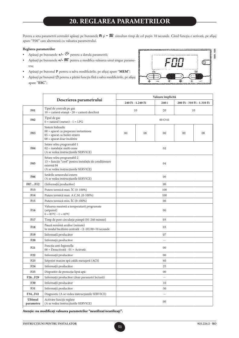
51925.224.2 - ROINSTRUCŢIUNI PENTRU INSTALATOR
Descrierea parametruluiValoare implicită
240 Fi - 1.240 Fi 240 i 280 Fi - 310 Fi - 1.310 Fi
F01 Tipul de centrală pe gaz10 = cameră etanşă - 20 = cameră deschisă 10 20 10
F02 Tipul de gaz0 = natural (metan) - 1 = LPG 00 O 01
F03
Sistem hidraulic00 = aparat cu preparare instantanee05 = aparat cu boiler extern08 = aparat doar încălzire
00 08 00 00 08
F04Setare releu programabil 102 = instalaţie multi-zone(A se vedea instrucţiunile SERVICE)
02
F05
Setare releu programabil 213 = funcţie “cool” pentru instalaţie de condiţionare externă 04(A se vedea instrucţiunile SERVICE)
04
F06 Setările senzorului extern(A se vedea instrucţiunile SERVICE) 00
F07…F12 (Informaţii producător) 00
F13 Putere termică max. ÎC (0-100%) 100
F14 Putere termică max. A.C.M. (0-100%) 100
F15 Putere termică min. ÎC (0-100%) 00
F16Valoarea maximă a temperaturii programate(setpoint)0 = 85°C - 1 = 45°C
00
F17 Timp de post-circulaţie pompă (01-240 minute) 03
F18 Pauză minimă arzător (minute)în modul încălzire centrală - (1-10) 00=10 secunde 03
F19 Informaţii producător 07
F20 Informaţii producător --
F21 Funcţia anti-legionella00 = Dezactivată - 01 = Activată 00
F22 Informaţii producător 00
F23 Setpoint maxim apă caldă menajeră (ACS) 60
F24 Informaţii producător 35
F25 Dispozitiv de protecţie lipsă apă 00
F26...F29 Informaţii producător (doar parametri lectură) --
F30 Informaţii producător 10
F31 Informaţii producător 30
F34...F41 Diagnostic (A se vedea instrucţiunile SERVICE) --
Ultimul parametru
Activare funcţie reglare(A se vedea instrucţiunile SERVICE) 00
atenţie: nu modificaţi valoarea parametrilor “neutilizat/neutilizaţi”.
Pentru a seta parametrii centralei apăsaţi pe butoanele R şi - simultan timp de cel puţin 10 secunde. Când funcţia e activată, pe afişaj apare “F00” care alternează cu valoarea parametrului.
reglarea parametrilor
• Apăsaţipebutoanele +/- pentru a derula parametrii;• Apăsaţipebutoanele +/- pentru a modifica valoarea unui singur parame-
tru;• Apăsaţipebutonul p pentru a salva modificările, pe afişaj apare “mem”;• Apăsaţipebutonul pentru a părăsi funcţia fără a salva modificările, pe afişaj
apare “esC”;
0605
_150
5
20. reglarea parametrilor
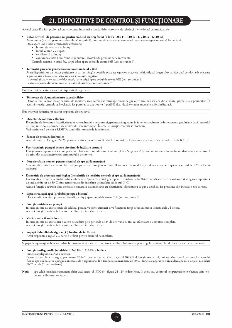
52925.224.2 - ROINSTRUCŢIUNI PENTRU INSTALATOR
Această centrală a fost proiectată cu respectarea întocmai a standardelor europene de referinţă şi este dotată cu următoarele:
• Buton(switch)depresiuneaerpentrumodelulcutirajforţat(240Fi-280Fi-310 fi - 1. 240 fi - 1.310 fi) Acest buton (switch) permite arzătorului să se aprindă, cu condiţia ca eficienţa conductei de evacuare a gazelor arse să fie perfectă. Dacă apare una dintre următoarele defecţiuni: • hornuldeevacuareeblocat; • tubulVenturieastupat; • ventilatoruleblocat; • conexiuneaîntretubulVenturişibutonul(switch)depresiuneaereîntreruptă; Centrala rămâne în stand-by, iar pe afişaj apare codul de eroare 03E (vezi secţiunea 9).
• Termostatgazearsepentrutirajnatural(modelul240i) Acest dispozitiv are un senzor poziţionat în partea stângă a hotei de evacuare a gazelor arse, care închide fluxul de gaz către arzător dacă conducta de evacuare
a gazelor arse e blocată sau dacă nu există presiune negativă. În această situaţie, centrala se blochează, iar pe afişaj apare codul de eroare 03E (vezi secţiunea 9). Pentru a aprinde din nou, imediat, arzătorul principal, vezi secţiunea 9.
Este interzisă dezactivarea acestui dispozitiv de siguranţă
• Termostatdesiguranţăpentrusupraîncălzire Datorită unui senzor plasat pe turul de încălzire, acest termostat întrerupe fluxul de gaz către arzător dacă apa din circuitul primar s-a supraîncălzit. În
această situaţie, centrala se blochează, iar pornirea sa din nou va fi posibilă doar după ce cauza anomaliei a fost înlăturată.
Este interzisă dezactivarea acestui dispozitiv de siguranţă
• Detectordeionizareaflăcării Electrodul de detectare a flăcării, situat în partea dreaptă a arzătorului, garantează siguranţa în funcţionare, în caz de întrerupere a gazului sau dacă intervalul
de timp între două aprinderi ale arzătorului este incomplet. În această situaţie, centrala se blochează. Vezi secţiunea 9 pentru a RESETA condiţiile normale de funcţionare.
• Senzordepresiunehidraulică Acest dispozitiv (3 - figura 24/25) permite aprinderea arzătorului principal numai dacă presiunea din instalaţie este mai mare de 0,5 bar.
• Post-circulaţiapompeipentrucircuituldeîncălzirecentrală Funcţionarea suplimentară a pompei, controlată electronic, durează 3 minute (F17 - Secţiunea 20), când centrala este în modul încălzire, după ce arzătorul
s-a stins din cauza intervenţiei termostatului de cameră.
• Post-circulaţiapompeipentrucircuituldeapăcaldămenajeră Sistemul de control electronic face ca pompa să mai funcţioneze încă 30 secunde, în modul apă caldă menajeră, după ce senzorul A.C.M. a închis
arzătorul.
• Dispozitivdeprotecţieanti-îngheţ(instalaţiiledeîncălzirecentralăşiapăcaldămenajeră) Controlul electronic al centralei include o funcţie de “protectie anti-îngheţ” pentru instalaţia de încălzire centrală, care face ca arzătorul să atingă o temperatură
de încălzire în tur de 30°C când temperatura din instalaţia de încălzire scade sub 5 °C. Această funcţie e activată când centrala e conectată la alimentarea cu electricitate, alimentarea cu gaz e deschisă, iar presiunea din instalaţie este corectă.
• Lipsacirculaţieiapei(probabilpompaeblocată) Dacă apa din circuitul primar nu circulă, pe afişaj apare codul de eroare 25E (vezi secţiunea 9).
• Funcţiaanti-blocarepompă În cazul în care nu există cerere de căldură, pompa va porni automat şi va funcţiona timp de un minut în următoarele 24 de ore. Această funcţie e activă când centrala e alimentată cu electricitate.
• Vanăcutreicăianti-blocare În cazul în care nu există nici o cerere de căldură pe o perioadă de 24 de ore, vana cu trei căi efectuează o comutare completă. Această funcţie e activă când centrala e alimentată cu electricitate.
• Supapăhidraulicădesiguranţă(circuituldeîncălzire) Acest dispozitiv e reglat la 3 bar şi e utilizat pentru circuitul de încălzire.
Supapa de siguranţă trebuie racordată la o conductă de evacuare prevăzută cu sifon. Folosirea sa pentru golirea circuitului de încălzire este strict interzisă.
• Funcţiaantilegionella(modelele1.240Fi-1.310Ficuboiler) Funcţia antilegionella NU e activată. Pentru a activa funcţia, reglaţi parametrul F21=01 (aşa cum se arată în paragraful 20). Când funcţia este activă, unitatea electronică de control a centralei
face ca apa din boiler să ajungă, la intervale de o săptămână, la o temperatură mai mare de 60°C ( funcţia e operativă numai dacă apa nu a depăşit niciodată 60°C în cele 7 zile anterioare).
notă: apa caldă menajeră e garantată chiar dacă senzorul NTC (5 - figura 24 - 25) e deteriorat. În acest caz, controlul temperaturii este efectuat prin tem-peratura din turul centralei.
21. dispozitive de Control şi funCţionare
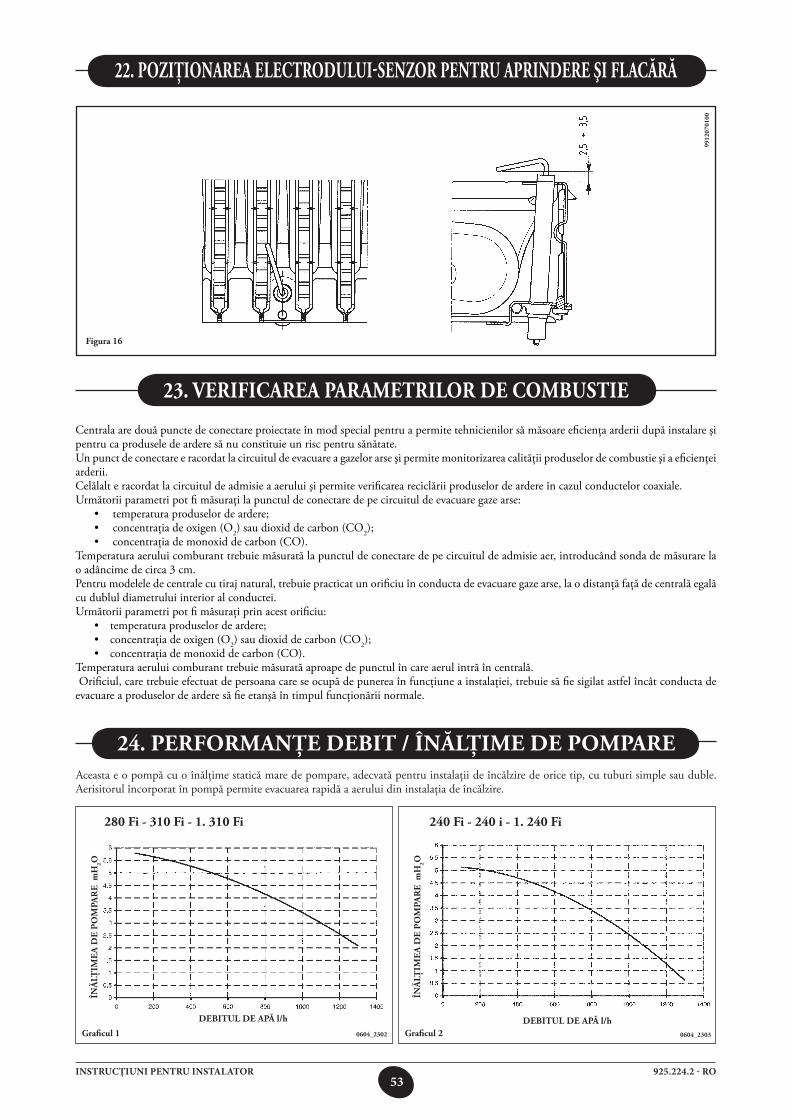
53925.224.2 - ROINSTRUCŢIUNI PENTRU INSTALATOR
22. poziţionarea eleCtrodului-senzor pentru aprindere şi flaCără
figura 16
9912
0701
00
Centrala are două puncte de conectare proiectate în mod special pentru a permite tehnicienilor să măsoare eficienţa arderii după instalare şi pentru ca produsele de ardere să nu constituie un risc pentru sănătate.Un punct de conectare e racordat la circuitul de evacuare a gazelor arse şi permite monitorizarea calităţii produselor de combustie şi a eficienţei arderii.Celălalt e racordat la circuitul de admisie a aerului şi permite verificarea reciclării produselor de ardere în cazul conductelor coaxiale.Următorii parametri pot fi măsuraţi la punctul de conectare de pe circuitul de evacuare gaze arse: • temperaturaproduselordeardere; • concentraţiadeoxigen(O2) sau dioxid de carbon (CO2); • concentraţiademonoxiddecarbon(CO).Temperatura aerului comburant trebuie măsurată la punctul de conectare de pe circuitul de admisie aer, introducând sonda de măsurare la o adâncime de circa 3 cm.Pentru modelele de centrale cu tiraj natural, trebuie practicat un orificiu în conducta de evacuare gaze arse, la o distanţă faţă de centrală egală cu dublul diametrului interior al conductei.Următorii parametri pot fi măsuraţi prin acest orificiu: • temperaturaproduselordeardere; • concentraţiadeoxigen(O2) sau dioxid de carbon (CO2); • concentraţiademonoxiddecarbon(CO).Temperatura aerului comburant trebuie măsurată aproape de punctul în care aerul intră în centrală. Orificiul, care trebuie efectuat de persoana care se ocupă de punerea în funcţiune a instalaţiei, trebuie să fie sigilat astfel încât conducta de evacuare a produselor de ardere să fie etanşă în timpul funcţionării normale.
23. verifiCarea parametrilor de Combustie
Aceasta e o pompă cu o înălţime statică mare de pompare, adecvată pentru instalaţii de încălzire de orice tip, cu tuburi simple sau duble. Aerisitorul încorporat în pompă permite evacuarea rapidă a aerului din instalaţia de încălzire.
graficul 1
24. performanţe debit / înălţime de pompare
debitul de apăl/h
înă
lţim
ea
de
po
mpa
re
mh
2o
0604_2302 graficul 2debitul de apăl/h
înă
lţim
ea
de
po
mpa
re
mh
2o
280 fi - 310 fi - 1. 310 fi
0604_2303
240 fi - 240 i - 1. 240 fi
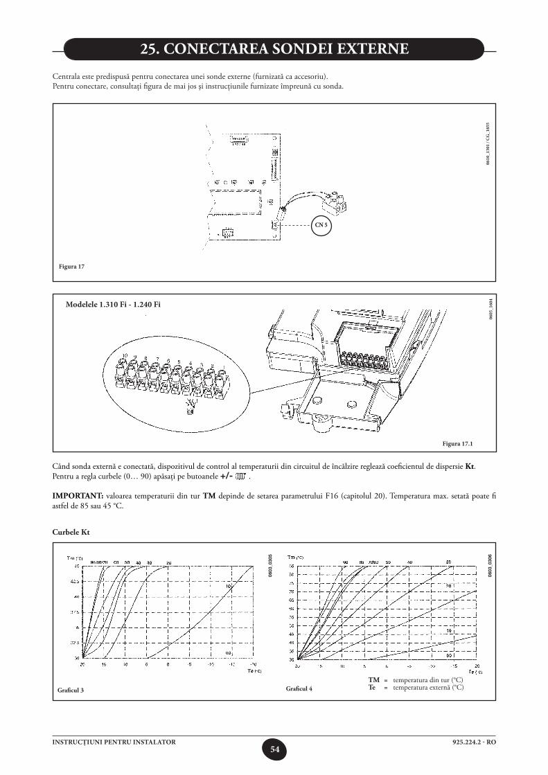
54925.224.2 - ROINSTRUCŢIUNI PENTRU INSTALATOR
Figura 17
0610
_130
1 / C
G_1
855
CN 5
0605
_160
4
Figura 17.1
Modelele 1.310 Fi - 1.240 Fi
25. ConeCtarea sondei externe
Centrala este predispusă pentru conectarea unei sonde externe (furnizată ca accesoriu).Pentru conectare, consultaţi figura de mai jos şi instrucţiunile furnizate împreună cu sonda.
Când sonda externă e conectată, dispozitivul de control al temperaturii din circuitul de încălzire reglează coeficientul de dispersie Kt. Pentru a regla curbele (0… 90) apăsaţi pe butoanele +/- .
important: valoarea temperaturii din tur tm depinde de setarea parametrului F16 (capitolul 20). Temperatura max. setată poate fi astfel de 85 sau 45 °C.
Curbele Kt
graficul 3
tm = temperatura din tur (°C)te = temperatura externă (°C)
0603
_030
5
0603
_030
6
graficul 4
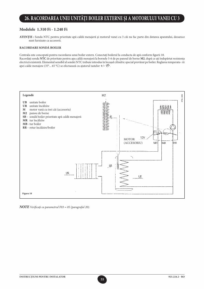
55925.224.2 - ROINSTRUCŢIUNI PENTRU INSTALATOR
Modelele 1.310 Fi - 1.240 Fi
ATENŢIE : Sonda NTC pentru prioritate apă caldă menajeră şi motorul vanei cu 3 căi nu fac parte din dotarea aparatului, deoarece sunt furnizate ca accesorii.
RACORDARE SONDĂ BOILER
Centrala este concepută pentru racordarea unui boiler extern. Conectaţi boilerul la conducta de apă conform figurii 18.Racordaţi sonda NTC de prioritate pentru apa caldă menajeră la bornele 5-6 de pe panoul de borne M2, după ce aţi îndepărtat rezistenţa electrică existentă. Elementul sensibil al sondei NTC trebuie introdus în locaşul cilindric special prevăzut pe boiler. Reglarea temperatu- rii apei calde menajere (35°... 65 °C) se efectuează cu ajutorul tastelor +/- .
26. RACORDAREA UNEI UNITĂŢI BOILER EXTERNE ŞI A MOTORULUI VANEI CU 3
Figura 18
Legendă
UB unitate boilerUR unitate încălzireM motor vană cu trei căi (accesoriu)M2 panou de borneSB - sondă boiler prioritate apă caldă menajerăMR tur încălzireMB - tur boilerRR - retur încălzire/boiler
MOTOR(ACCESORIU)
NOTE Verificaţi ca parametrul F03 = 05 (paragraful 20).
0702
_160
2
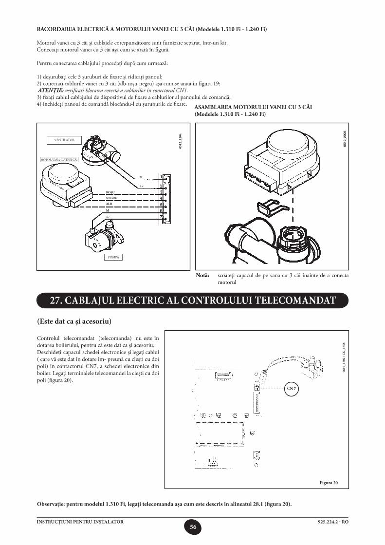
56925.224.2 - ROINSTRUCŢIUNI PENTRU INSTALATOR
(Este dat ca şi acesoriu)
Controlul telecomandat (telecomanda) nu este în dotarea boilerului, pentru că este dat ca şi acesoriu.Deschideţi capacul schedei electronice şi legaţi cablul ( care vă este dat în dotare îm- preună cu cleşti cu doi poli) în contactorul CN7, a schedei electronice din boiler. Legaţi terminalele telecomandei la cleşti cu doi poli (figura 20).
27. CABLAJUL ELECTRIC AL CONTROLULUI TELECOMANDAT
Figura 20
Observaţie: pentru modelul 1.310 Fi, legaţi telecomanda aşa cum este descris în alineatul 28.1 (figura 20).
0610
_130
2 / C
G_1
856
CN 7
RACORDAREAELECTRICĂAMOTORULUIVANEICU3CĂI(Modelele1.310Fi-1.240Fi)
Motorul vanei cu 3 căi şi cablajele corespunzătoare sunt furnizate separat, într-un kit.Conectaţi motorul vanei cu 3 căi aşa cum se arată în figură.
Pentru conectarea cablajului procedaţi după cum urmează:
1) deşurubaţi cele 3 şuruburi de fixare şi ridicaţi panoul;2) conectaţi cablurile vanei cu 3 căi (alb-roşu-negru) aşa cum se arată în figura 19; ATENŢIE: verificaţi blocarea corectă a cablurilor în conectorul CN1.3) fixaţi cablul cablajului de dispozitivul de fixare a cablurilor al panoului de comandă;4) închideţi panoul de comandă blocându-l cu şuruburile de fixare.
0512
_120
4
VENTILATOR
MOTOR VANĂ CU TREI CĂI
POMPĂ
alb
roşu
negru
m
4.c.
m
4.c.
asamblarea motorului vanei Cu 3 Căi (modelele 1.310 fi - 1.240 fi)
notă: scoateţi capacul de pe vana cu 3 căi înainte de a conecta motorul
0512
_200
5
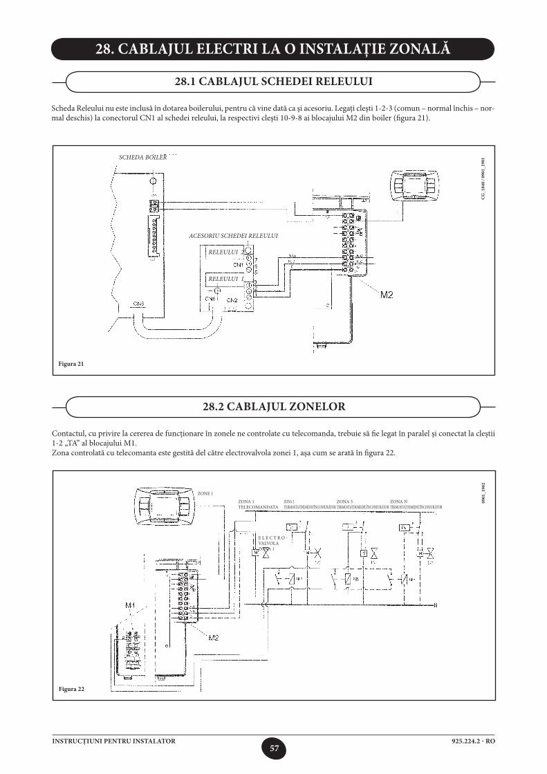
57925.224.2 - ROINSTRUCŢIUNI PENTRU INSTALATOR
28. CABLAJUL ELECTRI LA O INSTALAŢIE ZONALĂ
Scheda Releului nu este inclusă în dotarea boilerului, pentru că vine dată ca şi acesoriu. Legaţi cleşti 1-2-3 (comun – normal închis – nor- mal deschis) la conectorul CN1 al schedei releului, la respectivi cleşti 10-9-8 ai blocajului M2 din boiler (figura 21).
28.1 CABLAJUL SCHEDEI RELEULUI
SCHEDA BOILER
ACESORIU SCHEDEI RELEULUI
RELEULUI 2
RELEULUI 1
CG
_184
0 / 0
901_
1901
Figura 21
Contactul, cu privire la cererea de funcţionare în zonele ne controlate cu telecomanda, trebuie să fie legat în paralel şi conectat la cleştii1-2 „TA” al blocajului M1.Zona controlată cu telecomanta este gestită del către electrovalvola zonei 1, aşa cum se arată în figura 22.
28.2 CABLAJUL ZONELOR
ZONE 1
ZONA 1 TELECOMANDATA
0901
_190
2
Figura 22
E L E C T R O - VALVOLA ZONA 1
ZONA 2 TERMOSTATDEMEDIUÎNCONJURĂTOR
ZONA 3 TERMOSTATDEMEDIUÎNCONJURĂTOR
ZONA N TERMOSTATDEMEDIUÎNCONJURĂTOR
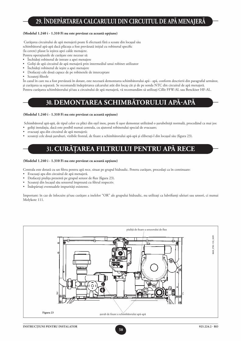
58925.224.2 - ROINSTRUCŢIUNI PENTRU INSTALATOR
0610
_270
1 / C
G_1
839
Figura 23 şurub de fixare a schimbătorului apă-apă
piuliţă de fixare a senzorului de flux
(Modelul1.240i-1.310Finuesteprevăzutcuaceastăopţiune)
Curăţarea circuitului de apă menajeră poate fi efectuată fără a scoate din locaşul săuschimbătorul apă-apă dacă plăcuţa a fost prevăzută iniţial cu robinetul specific (la cerere) plasat la ieşirea apei calde menajere.Pentru operaţiunile de curăţare este necesar să:• Închideţirobinetuldeintrareaapeimenajere• Goliţideapăcircuituldeapămenajerăprinintermediulunuirobinetutilizator• Închideţirobinetuldeieşireaapeimenajere• Desfaceţiceledouăcapacedeperobineteledeinterceptare• ScoateţifiltreleÎn cazul în care nu a fost prevăzută în dotare, este necesară demontarea schimbătorului apă - apă, conform descrierii din paragraful următor, şi curăţarea sa separată. Se recomandă îndepărtarea calcarului atât din locaş cât şi de pe sonda NTC din circuitul de apă menajeră.Pentru curăţarea schimbătorului şi/sau a circuitului de apă menajeră, vă recomandăm să utilizaţi Cillit FFW-AL sau Benckiser HF-AL.
29. îndepărtarea CalCarului din CirCuitul de apă menajeră
(Modelul1.240i-1.310Finuesteprevăzutcuaceastăopţiune)
Schimbătorul apă-apă, de tipul celor cu plăci din oţel inox, poate fi uşor demontat utilizând o şurubelniţă normală, procedând ca mai jos:• goliţiinstalaţia,dacăesteposibilnumaicentrala,cuajutorulrobinetuluispecialdeevacuare;• evacuaţiapadincircuituldeapămenajeră;• scoateţiceledouăşuruburi,vizibilefrontal,defixareaschimbătoruluiapă-apăşieliberaţi-ldinlocaşulsău(figura23).
30. demontarea sChimbătorului apă-apă
(Modelul1.240i-1.310Finuesteprevăzutcuaceastăopţiune)
Centrala este dotată cu un filtru pentru apă rece, situat pe grupul hidraulic. Pentru curăţare, procedaţi ca în continuare:• Evacuaţiapadincircuituldeapămenajeră.• Desfaceţipiuliţaprezentăpegrupulsenzordeflux(figura23).• Scoateţidinlocaşulsăusenzorulîmpreunăcufiltrulrespectiv.• Îndepărtaţieventualeleimpurităţiexistente.
Important: în caz de înlocuire şi/sau curăţare a inelelor “OR” ale grupului hidraulic, nu utilizaţi ca lubrifianţi uleiuri sau unsori, ci numai Molykote 111.
31. Curăţarea filtrului pentru apă reCe
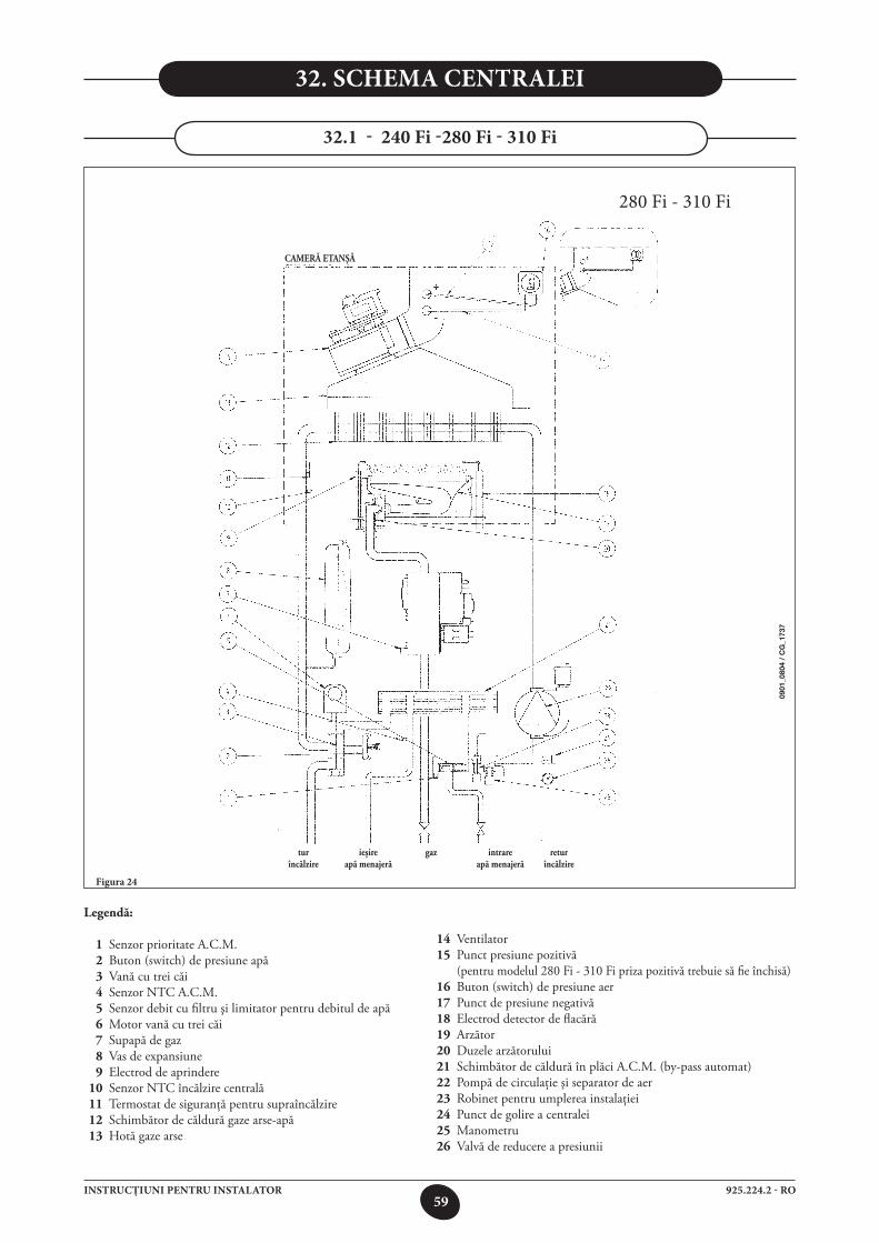
59925.224.2 - ROINSTRUCŢIUNI PENTRU INSTALATOR
Figura 24
32. SCHEMA CENTRALEI
32.1 - 240 Fi -280 Fi - 310 Fi
280 Fi - 310 Fi
legendă:
1 Senzor prioritate A.C.M. 2 Buton (switch) de presiune apă 3 Vană cu trei căi 4 Senzor NTC A.C.M. 5 Senzor debit cu filtru şi limitator pentru debitul de apă 6 Motor vană cu trei căi 7 Supapă de gaz 8 Vas de expansiune 9 Electrod de aprindere 10 Senzor NTC încălzire centrală 11 Termostat de siguranţă pentru supraîncălzire 12 Schimbător de căldură gaze arse-apă 13 Hotă gaze arse
14 Ventilator 15 Punct presiune pozitivă (pentru modelul 280 Fi - 310 Fi priza pozitivă trebuie să fie închisă) 16 Buton (switch) de presiune aer 17 Punct de presiune negativă 18 Electrod detector de flacără 19 Arzător 20 Duzele arzătorului 21 Schimbător de căldură în plăci A.C.M. (by-pass automat) 22 Pompă de circulaţie şi separator de aer 23 Robinet pentru umplerea instalaţiei 24 Punct de golire a centralei 25 Manometru 26 Valvă de reducere a presiunii
Cameră etanşă
tur ieşire gaz intrare retur încălzire apămenajeră apămenajeră încălzire
0901
_080
4 /
CG
_173
7
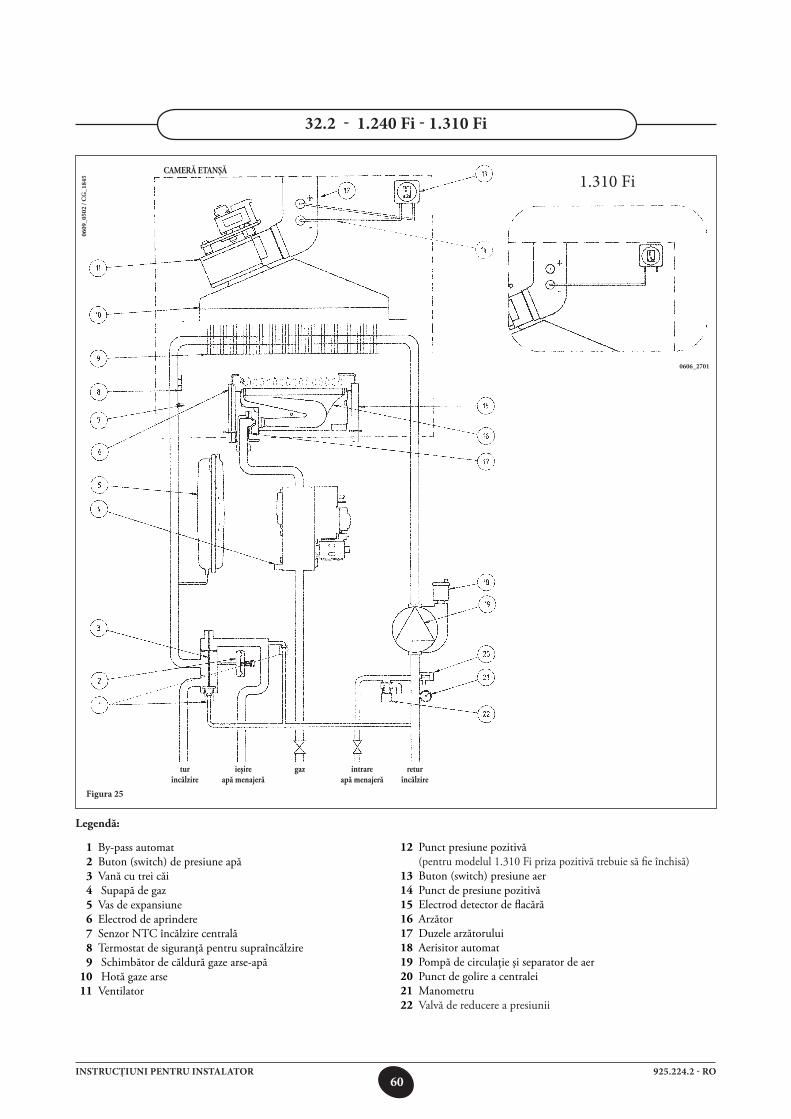
60925.224.2 - ROINSTRUCŢIUNI PENTRU INSTALATOR
Figura 25
0609
_050
2 / C
G_1
845
32.2 - 1.240 Fi - 1.310 Fi
Cameră etanşă
0606_2701
1.310 Fi
tur ieşire gaz intrare retur încălzire apămenajeră apămenajeră încălzire
legendă:
1 By-pass automat 2 Buton (switch) de presiune apă 3 Vană cu trei căi 4 Supapă de gaz 5 Vas de expansiune 6 Electrod de aprindere 7 Senzor NTC încălzire centrală 8 Termostat de siguranţă pentru supraîncălzire 9 Schimbător de căldură gaze arse-apă 10 Hotă gaze arse 11 Ventilator
12 Punct presiune pozitivă (pentru modelul 1.310 Fi priza pozitivă trebuie să fie închisă) 13 Buton (switch) presiune aer 14 Punct de presiune pozitivă 15 Electrod detector de flacără 16 Arzător 17 Duzele arzătorului 18 Aerisitor automat 19 Pompă de circulaţie şi separator de aer 20 Punct de golire a centralei 21 Manometru 22 Valvă de reducere a presiunii
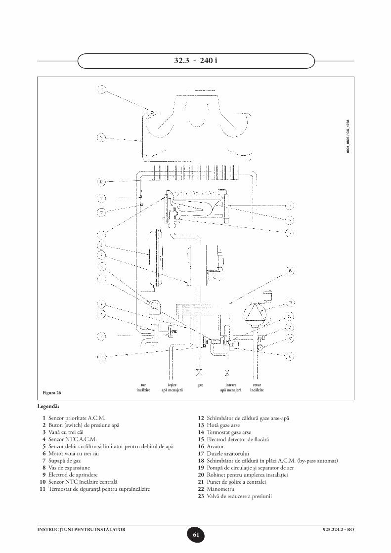
61925.224.2 - ROINSTRUCŢIUNI PENTRU INSTALATOR
32.3 - 240 i
Figura 26
legendă:
1 Senzor prioritate A.C.M. 2 Buton (switch) de presiune apă 3 Vană cu trei căi 4 Senzor NTC A.C.M. 5 Senzor debit cu filtru şi limitator pentru debitul de apă 6 Motor vană cu trei căi 7 Supapă de gaz 8 Vas de expansiune 9 Electrod de aprindere 10 Senzor NTC încălzire centrală 11 Termostat de siguranţă pentru supraîncălzire
12 Schimbător de căldură gaze arse-apă 13 Hotă gaze arse 14 Termostat gaze arse 15 Electrod detector de flacără 16 Arzător 17 Duzele arzătorului 18 Schimbător de căldură în plăci A.C.M. (by-pass automat) 19 Pompă de circulaţie şi separator de aer 20 Robinet pentru umplerea instalaţiei 21 Punct de golire a centralei 22 Manometru 23 Valvă de reducere a presiunii
tur ieşire gaz intrare retur încălzire apămenajeră apămenajeră încălzire
0901
_080
5 /
CG
_173
8
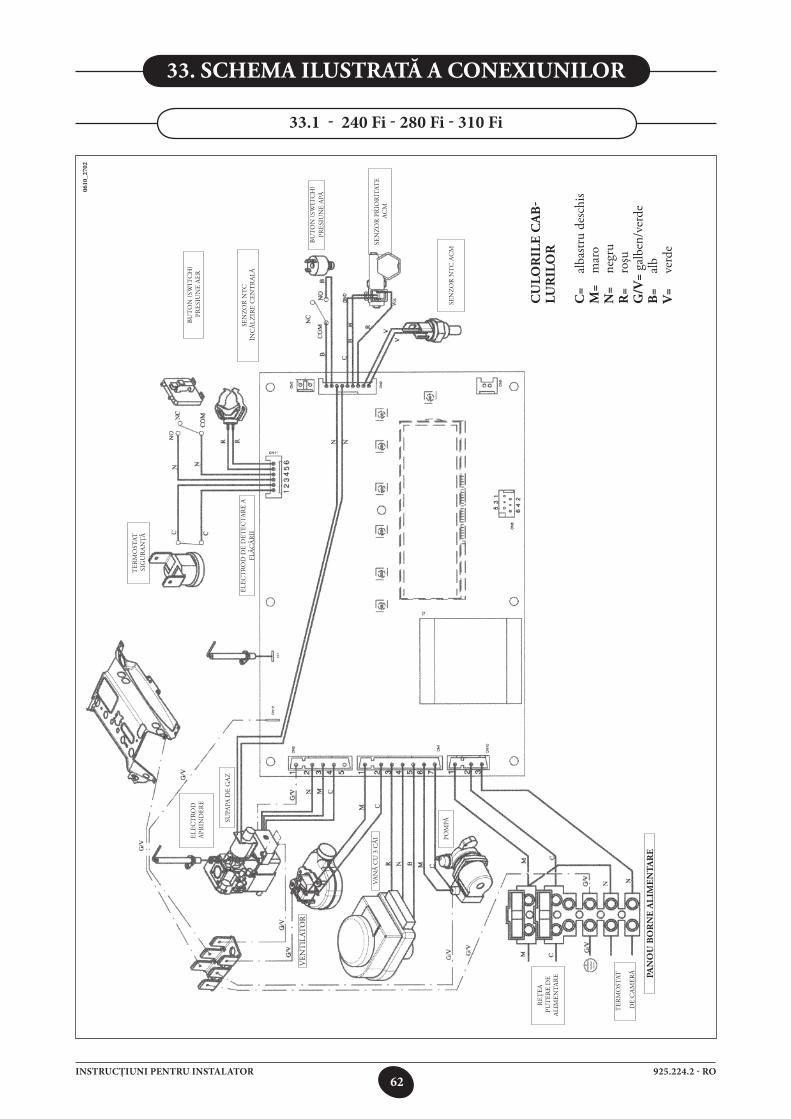
62925.224.2 - ROINSTRUCŢIUNI PENTRU INSTALATOR
33. sChema ilustrată a Conexiunilor
33.1 - 240 Fi - 280 Fi - 310 Fi
0610
_270
2
VEN
TIL
ATO
R
REŢ
EA P
UT
ERE
DE
ALI
MEN
TAR
E
TER
MO
STAT
S
IGU
RA
NŢĂ
ELEC
TRO
D A
PRIN
DER
E
VAN
Ă C
U 3
CĂ
I
SEN
ZOR
NT
C ÎN
CĂ
LZIR
E C
ENT
RA
LĂ
BUT
ON
(SW
ITC
H)
PR
ESIU
NE
AER
TER
MO
STAT
DE
CA
MER
Ă
ELEC
TRO
D D
E D
ETEC
TAR
E A
FLĂC
ĂR
II
BUT
ON
(SW
ITC
H)
PRES
IUN
E A
PĂ
SEN
ZOR
PR
IOR
ITAT
E A
CM
POM
PĂSE
NZO
R N
TC
AC
M
pan
ou
bo
rn
e a
lim
en
tar
e
SUPA
PA D
E G
AZ
Cu
lor
ile
Ca
b-
lur
ilo
r
C=
alba
stru
desc
his
m=
mar
on
= ne
gru
r=
roşu
g/v
= ga
lben
/ver
deb
= al
bv
= ve
rde

63925.224.2 - ROINSTRUCŢIUNI PENTRU INSTALATOR
33.2 - 1.240 Fi - 1.310 Fi
0705
_250
2
- - -
- -- -
- - -
Cu
lor
ile
Ca
blu
ril
or
C=
alba
stru
desc
his
m=
mar
on
= ne
gru
r=
roşu
g/v
= ga
lben
/ver
deb
= al
bv
= ve
rde
co
nn
ec
tio
n f
or
ex
te
rn
al
se
nso
r p
ro
be
(s
ee
se
ct
ion
25)
POM
PĂ
REŢ
EA P
UT
ERE
DE
ALI
MEN
TAR
E
TER
MO
STAT
DE
CA
MER
Ă pan
ou
bo
rn
e a
lim
en
tar
e
BUT
ON
(SW
ITC
H)
PR
ESIU
NE
APĂ
SEN
ZOR
NT
C ÎN
CĂ
LZIR
E C
ENT
RA
LĂ
TERM
OST
ATG
AZE
ARSE
TER
MO
STAT
S
IGU
RA
NŢĂ
ELEC
TRO
D D
E D
ETEC
TAR
E A
FLĂC
ĂR
II
ELEC
TRO
D D
E A
PRIN
DER
E
SUPA
PĂ D
E G
AZ
VEN
TIL
ATO
R
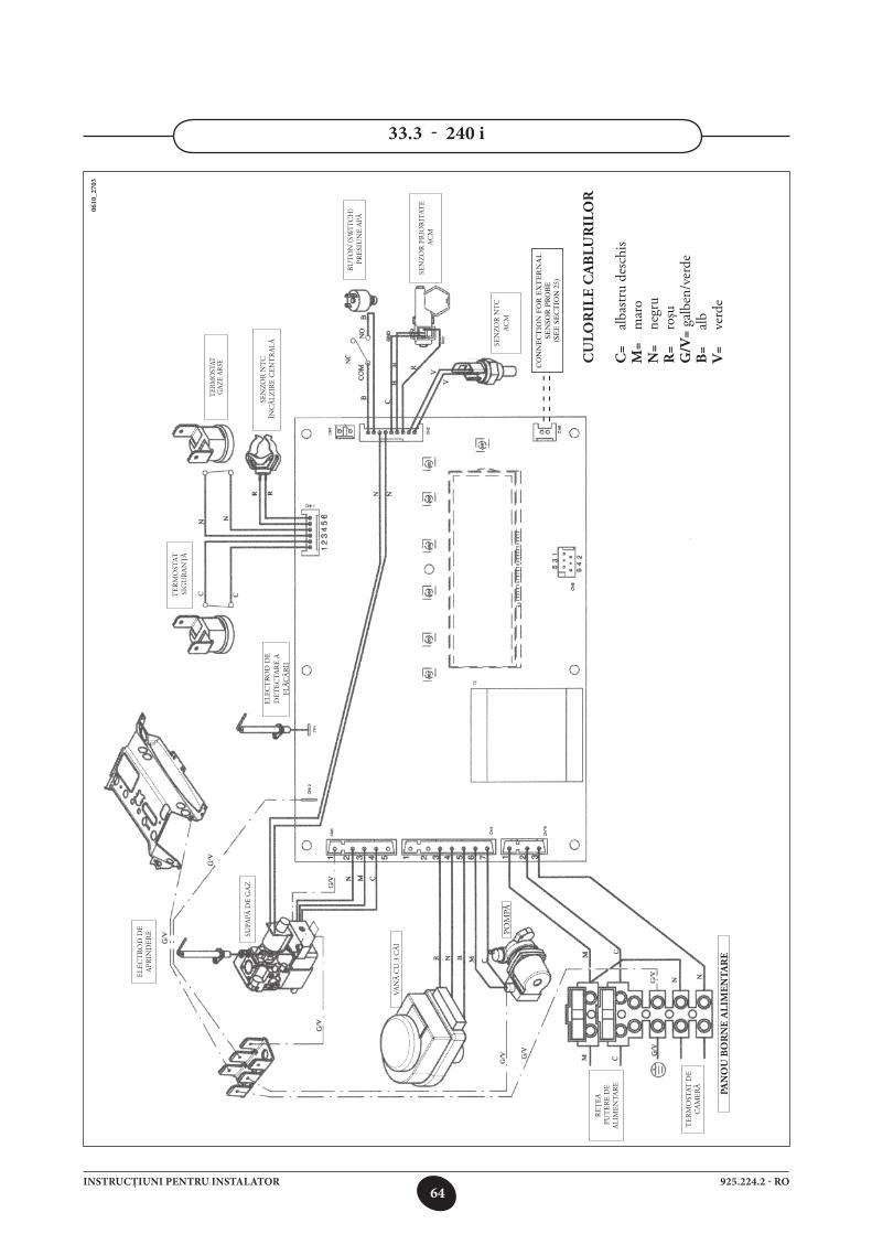
64925.224.2 - ROINSTRUCŢIUNI PENTRU INSTALATOR
33.3 - 240 i
0610
_270
3
Cu
lor
ile
Ca
blu
ril
or
C=
alba
stru
desc
his
m=
mar
on
= ne
gru
r=
roşu
g/v
= ga
lben
/ver
deb
= al
bv
= ve
rde
SEN
ZOR
NT
C
ACM
SEN
ZOR
PR
IOR
ITAT
E A
CM
BUT
ON
(SW
ITC
H)
PR
ESIU
NE
APĂ
SEN
ZOR
NT
C ÎN
CĂ
LZIR
E C
ENT
RA
LĂ
TERM
OST
ATG
AZE
ARSE
TER
MO
STAT
S
IGU
RA
NŢĂ
ELEC
TRO
D D
E D
ETEC
TAR
E A
FLĂC
ĂR
II
ELEC
TRO
D D
E A
PRIN
DER
E SUPA
PĂ D
E G
AZ
VAN
Ă C
U 3
CĂ
I
POM
PĂ
REŢ
EA P
UT
ERE
DE
ALI
MEN
TAR
E
TER
MO
STAT
DE
CA
MER
Ă
pan
ou
bo
rn
e a
lim
en
tar
e
- - -
- -- -
- - -
co
nn
ec
tio
n f
or
ex
te
rn
al
se
nso
r p
ro
be
(s
ee
se
ct
ion
25)
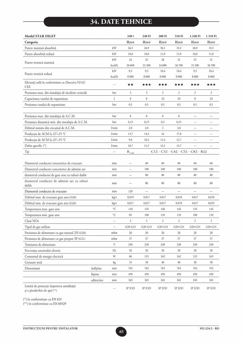
65925.224.2 - ROINSTRUCŢIUNI PENTRU INSTALATOR
34. date tehniCe
Model STAR DIGIT 240 i 240 Fi 280 Fi 310 Fi 1.240 Fi 1.310 Fi
Categoria II2H3P II2H3P II2H3P II2H3P II2H3P II2H3P
Putere maximă absorbită kW 26,3 26,9 30,1 33,3 26,9 33,3
Putere absorbită redusă kW 10,6 10,6 11,9 11,9 10,6 11,9
Putere termică maximă kW 24 25 28 31 25 31
kcal/h 20.600 21.500 24.080 26.700 21.500 26.700
Putere termică redusă kW 9,3 9,3 10,4 10,4 9,3 10,4
kcal/h 8.000 8.000 8.900 8.900 8.000 8.900
Eficienţă utilă în conformitate cu Directiva 92/42/CEE
— ★★ ★★★ ★★★ ★★★ ★★★ ★★★
Presiunea max. din instalaţia de încălzire centrală bar 3 3 3 3 3 3
Capacitatea vasului de expansiune l 8 8 10 10 8 10
Presiunea vasului de expansiune bar 0,5 0,5 0,5 0,5 0,5 0,5
Presiunea max. din instalaţia de A.C.M. bar 8 8 8 8 — —
Presiunea dinamică min. din instalaţia de A.C.M. bar 0,15 0,15 0,5 0,15 — —
Debitul minim din circuitul de A.C.M. l/min 2,0 2,0 2 2,0 — —
Producţia de ACM la ∆T=25 °C l/min 13,7 14,3 16 17,8 — —
Producţia de ACM la ∆T=35 °C l/min 9,8 10,2 11,4 12,7 — —
Debit specific (*) l/min 10,7 11,5 12,5 13,7 — —
Tip — B11BS C12 - C32 - C42 - C52 - C82 - B22
Diametrul conductei concentrice de evacuare mm — 60 60 60 60 60
Diametrul conductei concentrice de admisie aer mm — 100 100 100 100 100
diametrul conductei de gaze arse cu tuburi duble mm — 80 80 80 80 80
diametrul conductei de admisie aer cu tuburi duble
mm — 80 80 80 80 80
Diametrul conductei de evacuare mm 120 — — — — —
Debitul max. de evacuare gaze arse (G20) kg/s 0,019 0,017 0,017 0,018 0,017 0,018
Debitul min. de evacuare gaze arse (G20) kg/s 0,017 0,017 0,017 0,019 0,017 0,019
Temperatura max. gaze arse °C 110 135 140 145 135 145
Temperatura min. gaze arse °C 85 100 110 110 100 110
Clasă NOx — 3 3 3 3 3 3
Tipul de gaz utilizat — G20-G31 G20-G31 G20-G31 G20-G31 G20-G31 G20-G31
Presiunea de alimentare cu gaz natural 2H (G20) mbar 20 20 20 20 20 20
Presiunea de alimentare cu gaz propan 3P (G31) mbar 37 37 37 37 37 37
Tensiunea de alimentare V 230 230 230 230 230 230
Frecvenţa curentului electric Hz 50 50 50 50 50 50
Consumul de energie electrică W 80 135 165 165 135 165
Greutate netă kg 33 38 40 40 38 38
Dimensiuni înălţime mm 763 763 763 763 763 763
lăţime mm 450 450 450 450 450 450
adâncime mm 345 345 345 345 345 345
Limită de protecţie împotriva umidităţii şi a pierderilor de apă (**)
— IP X5D IP X5D IP X5D IP X5D IP X5D IP X5D
(*) în conformitate cu EN 625 (**) în conformitate cu EN 60529
66925.224.2 - HUUTASÍTÁSOK A FELHASZNÁLÓ RÉSZÉRE
Tisztelt Vásárló!Társaságunk meg van győződve arról, hogy az új kazánja minden igényét ki fogja elégíteni.Egy wESTEN termék megvásárlása biztosítja mindazt, amit Ön elvár: jó működést, egyszerű, racionális ha-sználatot.Azt kérjük Öntől ne tegye félre a jelen kézikönyvet amíg nem olvasta: a kazán helyes és hatékony használatához hasznos információkat talál benne.A csomagolóanyagokat (műanyag zacskók, polisztirol, stb.) gyermekektől távol kell tartani, mert veszélyforrást jelentenek.
A wESTEN kijelenti, hogy ezek a modellek rendelkeznek a CE márkajelzéssel, amely az alábbi irányelvek lényegi előírásainak teljesítését igazolja: - 90/396/EGK Gáz irányelv- 92/42/EGK Hozam irányelv- 2004/108/EGK Elektromágneses kompatibilitás irányelv - 2006/95/EK Kis feszültség irányelv
TARTALOMJEGYZÉK
A FELHASZNÁLÓNAK SZÓLÓ UTASÍTÁSOK
A FELSZERELÉST VÉGZŐ SZAKEMBERNEK SZÓLÓ UTASÍTÁSOK
1. A felszerelést megelőző utasítások 672. Az üzembe helyezést megelőző utasítások 673. A kazán üzembe helyezése 684. Központi fűtés (CH) és háztartási meleg víz (D.H.W.) hőmérséklet beállítás 695. A kazán feltöltése 706. A kazán kikapcsolása 707. Gázváltás 708. A rendszer hosszabb idejű üzemszünete Fagyvédelem 709. Hibaüzenetek és meghibásodási táblázat 7110. Szervizelési utasítások 71
11. Általános információ 7212. A felszerelést megelőző utasítások 7213. A kazán felszerelése 7314. A kazán mérete 7315. A füst és levegő vezetékek felszerelése 7416. A hálózati áramellátás csatlakoztatása 7817. Szobai termosztát felszerelése 7918. Gáz váltási módozatok 7919. Információs kijelző 8120. Paraméterek beállítása 8321. Ellenőrző és működtető eszközök 8422. A gyújtó és lángérzékelő elektróda elhelyezése 8523. Az égési paraméterek ellenőrzése 8524. Kimenő / szivattyú emelési magasság teljesítmények 8525. A külső mérőfej csatlakoztatása 8626. Külső vízmelegítő egység és 3 utas szelep motor bekötése 8727. A távvezérlés elektromos csatlakoztatása 8828. Elektromos csatlakoztatás zónás berendezéshez 8929. A hálózati kör vízkőtől való megtisztítása 9030. A víz-víz hőcserélő szétszerelése 9031. A hidegvízszűrő tisztítása 9032. A kazán vázlatrajza 91-9333. Illusztrált huzalozási rajz 94-9634. Műszaki adatok 97
67925.224.2 - HUUTASÍTÁSOK A FELHASZNÁLÓ RÉSZÉRE
Ezt a kazánt atmoszférikus nyomáson a forrási hőmérsékletnél alacsonyabb hőmérsékletű víz melegítésére terveztük. A kazánt központi fűtő rendszerhez és háztartási meleg víz ellátó rendszerhez kell csatlakoztatni a teljesítményeinek és a kimenő teljesítményének megfelelően.A kazán felszerelését képesített szervizmérnökkel végeztesse, és biztosítsa az alábbi műveletek elvégzését:
a) Gondos ellenőrzés arra vonatkozóan, hogy a kazán alkalmas-e a rendelkezésre álló gázfajtával való üzemelésre. További részletes utasítások a csomagoláson és a készüléken lévő címkén találhatók.
b) annak gondos ellenőrzése, hogy a füstelvezető végződés huzatja megfelelő-e; nincs-e elzáródva, és hogy nincsenek-e más készülék füstgázai ugyanazon füstcsatornán át elvezetve, hacsak nem kifejezetten arra tervezték, hogy egynél több készülékből érkező füstgáz összegyűjtését végezze, a hatályos törvényeknek és rendelkezéseknek megfelelően.
c) Annak gondos ellenőrzése, hogy abban az esetben, ha a füstöt már meglévő füstcsatornákhoz csatlakoztatják, alapos tisztítás legyen elvé-gezve, nehogy abból maradék égéstermékek kerülhessenek ki a kazán működése során és elzárják a füstcsatornát.
d) A készülék helyes üzemeltetésének biztosítására és a garancia érvényessége elvesztésének elkerülésére ügyeljen az alábbi óvórendszabályokra:
1. Meleg víz áramkör:
1.1. Ha a víz keménysége nagyobb, mint 20 °F (1 °F = 10 mg kalcium karbonát/1 liter víz), akkor polifoszfát vagy hasonló kezelést kell végezni a hatályos rendelkezések betartásával.
1.2. A háztartási meleg vizes áramkört alaposan át kell öblíteni a készülék felszerelése után és annak használata előtt.1.3. A termék használati melegvíz hálózatához használt anyagok megfelelnek a 98/83/EK direktívának.
2. Fűtési áramkör
2.1. Új rendszer A kazán felszerelése előtt a rendszert alaposan meg kell tisztítani, és át kell öblíteni a maradék menetvágási forgács, forraszanyag és
az esetleges oldószerek eltávolítása céljából, alkalmas termékek használatával. A fém, műanyag és gumi alkatrészek károsodásának elkerülésére csak semleges hatású, vagyis nem savas és nem lúgos, tisztítószereket
használjon. A tisztításhoz ajánlott termékek: SENTINEL X300 vagy X400 és FERNOX fűtőáramkör helyreállító. Ennek a terméknek a használatánál kövesse szigorúan a gyártó
útmutatásait.2.2. Meglévő rendszer A kazán felszerelése előtt a rendszert alaposan meg kell tisztítani a maradék iszaptól és szennyeződésektől, és át kell öblíteni a 2.1
fejezetben ismertetett alkalmas termékek használatával. A fém, műanyag és gumi alkatrészek károsodásának elkerülésére csak olyan semleges hatású, vagyis nem savas és nem lúgos,
tisztítószereket használjon, mint a SENTINEL X100 és FERNOX fűtőáramkör védőszer Ennek a terméknek a használatánál kövesse szigorúan a gyártó útmutatásait.
Ne feledje, hogy idegen anyag jelenléte a fűtési rendszerben károsan befolyásolja a kazán működését (pl. túlmelegedést és a hőcserélő zajos működését okozza).
A fentiek betartásának elmulasztása a garancia elvesztését vonja maga után.
1. A Felszerelést Megelőző utAsítások
A kazán kezdeti begyújtását engedéllyel rendelkező technikusnak kell elvégezni. Biztosítsa az alábbi műveletek elvégzését:
a) Az (elektromos, víz, gáz) ellátó rendszerek beállításainak megfelelő kazánparaméterek.b) A hatályos törvényeknek és rendelkezéseknek megfelelő felszerelés.c) Az áramellátás és a készülék földelésének megfelelő csatlakoztatása.
A fentiek betartásának elmulasztása a garancia elvesztését vonja maga után.Az üzembe helyezést megelőzően távolítsa el a védő műanyag bevonatot az egységről. Ehhez ne használjon semmilyen szerszámot vagy dör-zshatású tisztítószert, mert ezzel rongálhatja a festett felületeket.
A készüléket nem használhatják olyan személyek (gyermekeket ideértve) akik csökkent fizikai, érzéki vagy szellemi képességgel ren-delkeznek, vagy nem rendelkeznek megfelelő tapasztalattal és tudással, hacsak egy felelős személy közvetítésén keresztül nem kerül garantálásra a biztonságuk illetve felügyeletük, vagy a készülék használatára vonatkozóan fel nem világosították őket.
2. Az üzeMbe helyezést Megelőző utAsítások
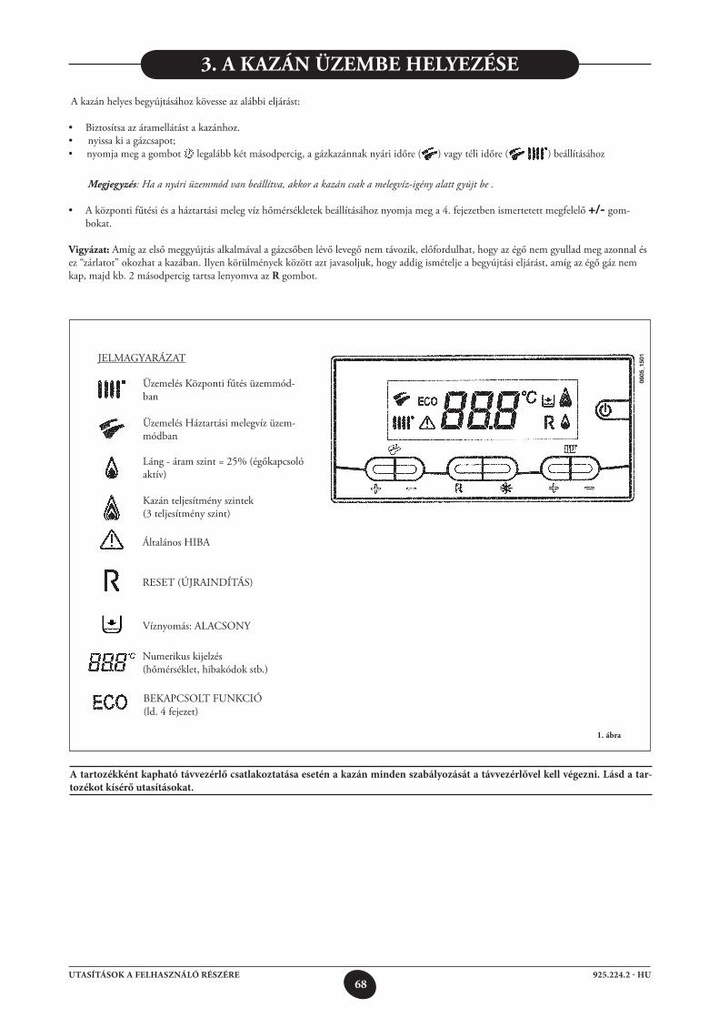
68925.224.2 - HUUTASÍTÁSOK A FELHASZNÁLÓ RÉSZÉRE
A tartozékként kapható távvezérlő csatlakoztatása esetén a kazán minden szabályozását a távvezérlővel kell végezni. Lásd a tar-tozékot kísérő utasításokat.
3. A kAzán üzeMbe helyezése
1. ábra
A kazán helyes begyújtásához kövesse az alábbi eljárást:
• Biztosítsaazáramellátástakazánhoz.• nyissakiagázcsapot;• nyomja meg a gombot legalább két másodpercig, a gázkazánnak nyári időre ( ) vagy téli időre ( ) beállításához
Megjegyzés: Ha a nyári üzemmód van beállítva, akkor a kazán csak a melegvíz-igény alatt gyújt be .
• Aközpontifűtésiésaháztartásimelegvízhőmérsékletekbeállításáhoznyomjamega4.fejezetbenismertetettmegfelelő+/- gom-bokat.
Vigyázat: Amíg az első meggyújtás alkalmával a gázcsőben lévő levegő nem távozik, előfordulhat, hogy az égő nem gyullad meg azonnal és ez “zárlatot” okozhat a kazában. Ilyen körülmények között azt javasoljuk, hogy addig ismételje a begyújtási eljárást, amíg az égő gáz nem kap, majd kb. 2 másodpercig tartsa lenyomva az r gombot.
0605
_150
1JELMAGYARÁZAT
Üzemelés Központi fűtés üzemmód-ban
Általános HIBA
Víznyomás: ALACSONY
Numerikus kijelzés (hőmérséklet, hibakódok stb.)
RESET (ÚJRAINDÍTÁS)
BEKAPCSOLT FUNKCIÓ (ld. 4 fejezet)
Láng - áram szint = 25% (égőkapcsoló aktív)
Kazán teljesítmény szintek (3 teljesítmény szint)
Üzemelés Háztartási melegvíz üzem-módban
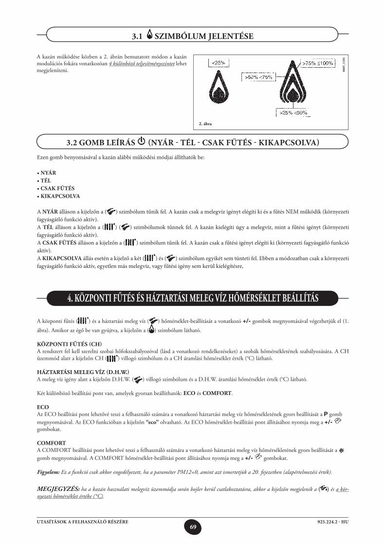
69925.224.2 - HUUTASÍTÁSOK A FELHASZNÁLÓ RÉSZÉRE
0605
_110
1
3.2 GOMB LEÍRÁS (NYÁR - TÉL - CSAK FŰTÉS - KIKAPCSOLVA)
A kazán működése közben a 2. ábrán bemutatott módon a kazán modulációs fokára vonatkozóan 4 különböző teljesítményszintet lehet megjeleníteni.
3.1 sziMbóluM jelentése
2. ábra
4. központi Fűtés és háztArtási Meleg Víz hőMérséklet beállítás
A központi fűtés ( ) és a háztartási meleg víz ( ) hőmérséklet-beállítását a vonatkozó +/- gombok megnyomásával végezhetjük el (1. ábra). Amikor az égő be van gyújtva, a kijelzőn a ( ) szimbólum látható.
központi Fűtés (Ch)A rendszert fel kell szerelni szobai hőfokszabályozóval (lásd a vonatkozó rendelkezéseket) a szobák hőmérsékletének szabályozására. A CH üzemmód alatt a kijelzőn CH ( ) villogó szimbólum és a CH áramlási hőmérséklet érték (°C) látható.
háztArtási Meleg Víz (D.h.W.)A meleg víz igény alatt a kijelzőn D.H.W. ( ) villogó szimbólum és a D.H.W. áramlási hőmérséklet érték (°C) látható.
Két különböző beállítási pont van, amelyek gyorsan beállíthatók: eCo és CoMFort.
eCoAz ECO beállítási pont lehetővé teszi a felhasználó számára a vonatkozó háztartási meleg víz hőmérsékletének gyors beállítását a P gomb megnyomásával. Az ECO funkcióban a kijelzőn “eco” olvasható. Az ECO hőmérséklet-beállítási pont állításához nyomja meg a +/- gombokat.
CoMFortA COMFORT beállítási pont lehetővé teszi a felhasználó számára a vonatkozó háztartási meleg víz hőmérsékletének gyors beállítását a gomb megnyomásával. A COMFORT hőmérséklet-beállítási pont állításához nyomja meg a +/- gombokat.
Figyelem: Ez a funkció csak akkor engedélyezett, ha a paraméter PM12=0, amint azt ismertetjük a 20. fejezetben (alapértelmezési érték).
MEGJEGYZÉS: ha a kazán használati melegvíz üzemmódja során bojler kerül csatlakoztatásra, akkor a kijelzőn megjelenik a ( ) és a kör-nyezeti hőmérséklet értéke (°C).
Ezen gomb benyomásával a kazán alábbi működési módjai állíthatók be:
• NYÁR• TÉL• CSAK FŰTÉS• KIKAPCSOLVA
A NYÁR álláson a kijelzőn a ( ) szimbólum tűnik fel. A kazán csak a melegvíz igényt elégíti ki és a fűtés NEM működik (környezeti fagyásgátló funkció aktív). A TÉL álláson a kijelzőn a ( ) ( ) szimbólumok tűnnek fel. A kazán kielégíti úgy a melegvíz, mint a fűtési igényt (környezeti fagyásgátló funkció aktív). A CSAK FŰTÉS álláson a kijelzőn a ( ) szimbólum tűnik fel. A kazán csak a fűtési igényt elégíti ki (környezeti fagyásgátló funkció aktív). A KIKAPCSOLVA állás esetén a kijelző a két ( ) és ( ) szimbólum egyikét sem tünteti fel. Ebben a módozatban csak a környezeti fagyásgátló funkció aktív, egyetlen más melegvíz, vagy fűtési igény sem kerül kielégítésre,
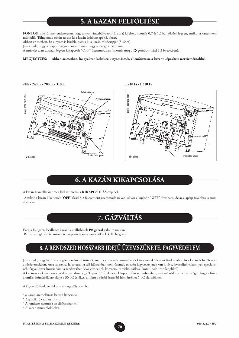
70925.224.2 - HUUTASÍTÁSOK A FELHASZNÁLÓ RÉSZÉRE
Fontos: Ellenőrizze rendszeresen, hogy a nyomásszabályozón (3. ábra) kijelzett nyomás 0,7 és 1,5 bar közötti legyen, amikor a kazán nem működik. Túlnyomás esetén nyissa ki a kazán ürítőszelepé (3. ábra).Abban az esetben, ha a nyomás kisebb, nyissa ki a kazán töltőcsapját (3. ábra).Javasoljuk, hogy a csapot nagyon lassan nyissa, hogy a levegő eltávozzon.A művelet alatt a kazán legyen kikapcsolt “OFF” üzemmódban (nyomja meg a gombot - lásd 3.2 fejezetben).
Megjegyzés: Abban az esetben, ha gyakran keletkezik nyomásesés, ellenőriztesse a kazánt képesített szervizmérnökkel.
5. A kAzán Feltöltése
A kazán áramellátását meg kell szüntetni a kikApCsolás céljából.
Amikor a kazán kikapcsolt “oFF” (lásd 3.2 fejezetben) üzemmódban van, akkor a kijelzőn “oFF” olvasható, de az alaplap továbbra is áram alatt van.
6. A kAzán kikApCsolásA
7. gázVáltás
Ezek a földgázra beállított kazánok átállíthatók pb gázzal való üzemelésre. Bármilyen gázváltási műveletet képesített szervizmérnöknek kell elvégezni.
Javasoljuk, hogy kerülje az egész rendszer leürítését, mert a vízcsere haszontalan és káros mészkő lerakódásokat idéz elő a kazán belsejében és a fűtőelemekben. Arra az esetre, ha a kazán a téli időszakban nem üzemel, és ezért fagyveszélynek van kitéve, javasoljuk valamilyen speciális-célú fagyállószer hozzáadását a rendszerben lévő vízhez (pl. korrózió- és vízkő-gátlóval kombinált propilénglikol).A kazánok elektronikus vezérlése tartalmaz egy “fagyvédő” funkciót a központi fűtési rendszerben, ami működésbe hozza az égőt, hogy a fűtés áramlási hőmérséklete elérje a 30 oC értéket, amikor a fűtési áramlási hőmérséklet 5 oC alá csökken.
A fagyvédő funkció akkor van engedélyezve, ha:
* a kazán áramellátása be van kapcsolva;* A gázellátó csap nyitva van;* A rendszer nyomása az előírás szerinti;* A kazán nincs blokkolva.
8. A renDszer hosszAbb iDejű üzeMszünete. FAgyVéDeleM
3a. ábra
Feltöltő csap
leürítési pont
nyomásmérő
3b. ábra
0603
_130
3/C
G_1
791
Feltöltő csap
240i - 240 Fi - 280 Fi - 310 Fi 1.240 Fi - 1.310 Fi
0901
_080
2 /
CG
_179
1
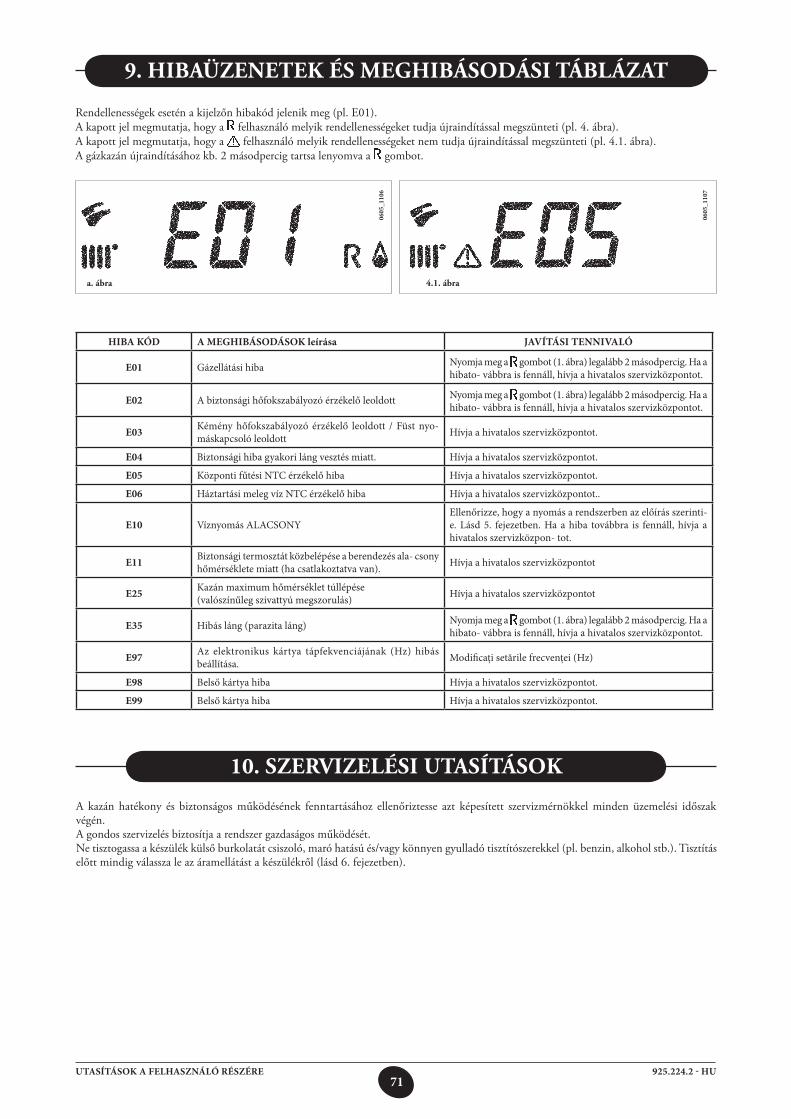
71925.224.2 - HUUTASÍTÁSOK A FELHASZNÁLÓ RÉSZÉRE
HIBA KÓD A MEGHIBÁSODÁSOK leírása JAVÍTÁSI TENNIVALÓ
E01 Gázellátási hiba Nyomja meg a gombot (1. ábra) legalább 2 másodpercig. Ha a hibato- vábbra is fennáll, hívja a hivatalos szervizközpontot.
E02 A biztonsági hőfokszabályozó érzékelő leoldott Nyomja meg a gombot (1. ábra) legalább 2 másodpercig. Ha a hibato- vábbra is fennáll, hívja a hivatalos szervizközpontot.
E03 Kémény hőfokszabályozó érzékelő leoldott / Füst nyo- máskapcsoló leoldott Hívja a hivatalos szervizközpontot.
E04 Biztonsági hiba gyakori láng vesztés miatt. Hívja a hivatalos szervizközpontot.
E05 Központi fűtési NTC érzékelő hiba Hívja a hivatalos szervizközpontot.
E06 Háztartási meleg víz NTC érzékelő hiba Hívja a hivatalos szervizközpontot..
E10 Víznyomás ALACSONYEllenőrizze, hogy a nyomás a rendszerben az előírás szerinti-e. Lásd 5. fejezetben. Ha a hiba továbbra is fennáll, hívja a hivatalos szervizközpon- tot.
E11 Biztonsági termosztát közbelépése a berendezés ala- csony hőmérséklete miatt (ha csatlakoztatva van). Hívja a hivatalos szervizközpontot
E25 Kazán maximum hőmérséklet túllépése(valószínűleg szivattyú megszorulás) Hívja a hivatalos szervizközpontot
E35 Hibás láng (parazita láng) Nyomja meg a gombot (1. ábra) legalább 2 másodpercig. Ha a hibato- vábbra is fennáll, hívja a hivatalos szervizközpontot.
E97 Az elektronikus kártya tápfekvenciájának (Hz) hibás beállítása. Modificaţi setările frecvenţei (Hz)
E98 Belső kártya hiba Hívja a hivatalos szervizközpontot.
E99 Belső kártya hiba Hívja a hivatalos szervizközpontot.
0605
_110
6
0605
_110
7
9. hibAüzenetek és MeghibásoDási táblázAt
Rendellenességek esetén a kijelzőn hibakód jelenik meg (pl. E01). A kapott jel megmutatja, hogy a felhasználó melyik rendellenességeket tudja újraindítással megszünteti (pl. 4. ábra). A kapott jel megmutatja, hogy a felhasználó melyik rendellenességeket nem tudja újraindítással megszünteti (pl. 4.1. ábra). A gázkazán újraindításához kb. 2 másodpercig tartsa lenyomva a gombot.
a. ábra 4.1. ábra
A kazán hatékony és biztonságos működésének fenntartásához ellenőriztesse azt képesített szervizmérnökkel minden üzemelési időszak végén.A gondos szervizelés biztosítja a rendszer gazdaságos működését.Ne tisztogassa a készülék külső burkolatát csiszoló, maró hatású és/vagy könnyen gyulladó tisztítószerekkel (pl. benzin, alkohol stb.). Tisztítás előtt mindig válassza le az áramellátást a készülékről (lásd 6. fejezetben).
10. szerVizelési utAsítások
72925.224.2 - HUUTASÍTÁSOK A SZERELŐ RÉSZÉRE
Ezt a kazánt atmoszférikus nyomáson a forrási hőmérsékletnél alacsonyabb hőmérsékletű víz melegítésére terveztük. A kazánt központi fűtő rendszerhez és háztartási meleg víz ellátó rendszerhez kell csatlakoztatni a teljesítményeinek és a kimenő teljesítményének megfelelően.A kazán felszerelését képesített szervizmérnökkel végeztesse, és biztosítsa az alábbi műveletek elvégzését:
a) Gondos ellenőrzés arra vonatkozóan, hogy a kazán alkalmas-e a rendelkezésre álló gázfajtával való üzemelésre. További részletes utasítások a csomagoláson és a készüléken lévő címkén találhatók.
b) annak gondos ellenőrzése, hogy a füstelvezető végződés huzatja megfelelő-e; nincs-e elzáródva, és hogy nincsenek-e más készülék füstgázai ugyanazon füstcsatornán át elvezetve, hacsak nem kifejezetten arra tervezték, hogy egynél több készülékből érkező füstgáz összegyűjtését végezze, a hatályos törvényeknek és rendelkezéseknek megfelelően.
c) Annak gondos ellenőrzése, hogy abban az esetben, ha a füstöt már meglévő füstcsatornákhoz csatlakoztatják, alapos tisztítás legyen elvé-gezve, nehogy abból maradék égéstermékek kerülhessenek ki a kazán működése során és elzárják a füstcsatornát.
A készülék helyes üzemeltetésének biztosítására és a garancia érvényessége elvesztésének elkerülésére, ügyeljen az alábbi óvórendszabályokra:
1. Meleg víz áramkör:
1.1. Ha a víz keménysége nagyobb, mint 20 °F (1 °F = 10 mg kalcium karbonát/1 liter víz), akkor polifoszfát vagy hasonló kezelést kell végezni a hatályos rendelkezések betartásával.
1.2. A háztartási meleg vizes áramkört alaposan át kell öblíteni a készülék felszerelése után és annak használata előtt.
1.3. A termék használati melegvíz hálózatához használt anyagok megfelelnek a 98/83/EK direktívának.
2. Fűtési áramkör
2.1. Új rendszer A kazán felszerelése előtt a rendszert alaposan meg kell tisztítani, és át kell öblíteni a maradék menetvágási forgács, forraszanyag és
az esetleges oldószerek eltávolítása céljából, alkalmas termékek használatával. A fém, műanyag és gumi alkatrészek károsodásának elkerülésére csak semleges hatású, vagyis nem savas és nem lúgos, tisztítószereket
használjon. A tisztításhoz ajánlott termékek: SENTINEL X300 vagy X400 és FERNOX fűtőáramkör helyreállító. Ennek a terméknek a használatánál kövesse szigorúan a gyártó
útmutatásait.
2.2. Meglévő rendszer A kazán felszerelése előtt a rendszert alaposan meg kell tisztítani a maradék iszaptól és szennyeződésektől, és át kell öblíteni a 2.1
fejezetben ismertetett alkalmas termékek használatával. A fém, műanyag és gumi alkatrészek károsodásának elkerülésére csak olyan semleges hatású, vagyis nem savas és nem lúgos,
tisztítószereket használjon, mint a SENTINEL X100 és FERNOX fűtőáramkör védőszer Ennek a terméknek a használatánál kövesse szigorúan a gyártó útmutatásait.
Ne feledje, hogy idegen anyag jelenléte a fűtési rendszerben károsan befolyásolja a kazán működését (pl. túlmelegedést és a hőcserélő zajos működését okozza).
A fentiek betartásának elmulasztása a garancia elvesztését vonja maga után.
12. A Felszerelést Megelőző utAsítások
Az alábbi megjegyzések és utasítások a szervizmérnököknek szólnak, hogy segítse őket a telepítés hibátlan elvégzésében. A kazán begyújtására és az üzemeltetésére vonatkozó utasítások a ‘Felhasználóra tartozó utasítások’ című fejezetben találhatók.Vegye figyelembe, hogy a háztartási gázkészülékek felszerelését, karbantartását és működtetését kizárólag szakképzett személyek végezhetik az érvényes szabványoknak megfelelően.Kérjük, jegyezze meg az alábbiakat:* Ez a kazán csatlakoztatható bármilyen típusú kettős vagy egyes tápcsövű konvektor lapokhoz, radiátorokhoz és termokonvektorhoz. A
rendszerszakaszok tervezését a szokásos módon kell végezni, azonban figyelembe kell venni a rendelkezésre álló kimenő teljesítményt / szivattyú emelési magasságot, a 24. fejezetben leírtak szerint.
* Ne hagyja a csomagolás bármely részét (műanyag zsákok, polisztirol stb.) gyermekek által elérhető helyen, mert ezek potenciális veszély-források.
* A kazán kezdeti begyújtását képesített szervizmérnöknek kell elvégezni. A fentiek betartásának elmulasztása a garancia elvesztését vonja maga után.
11. áltAlános inForMáCió
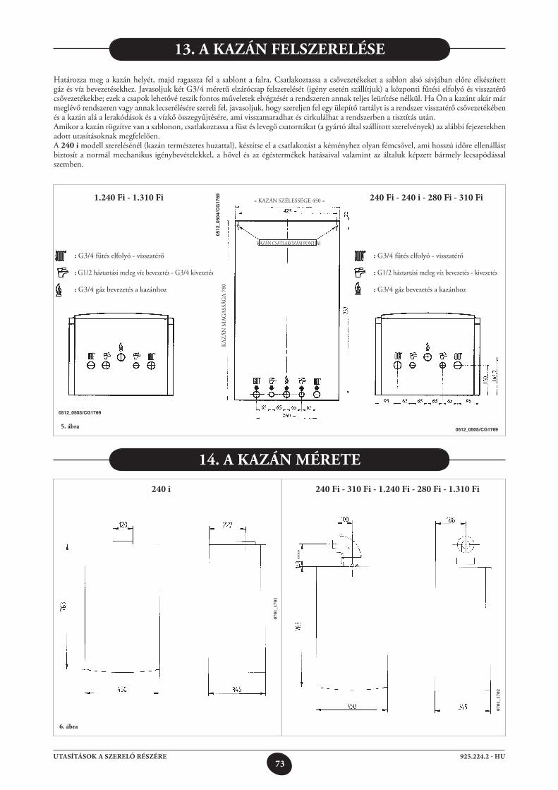
73925.224.2 - HUUTASÍTÁSOK A SZERELŐ RÉSZÉRE
13. A kAzán Felszerelése
Határozza meg a kazán helyét, majd ragassza fel a sablont a falra. Csatlakoztassa a csővezetékeket a sablon alsó sávjában előre elkészített gáz és víz bevezetésekhez. Javasoljuk két G3/4 méretű elzárócsap felszerelését (igény esetén szállítjuk) a központi fűtési elfolyó és visszatérő csővezetékekbe; ezek a csapok lehetővé teszik fontos műveletek elvégzését a rendszeren annak teljes leürítése nélkül. Ha Ön a kazánt akár már meglévő rendszeren vagy annak lecserélésére szereli fel, javasoljuk, hogy szereljen fel egy ülepítő tartályt is a rendszer visszatérő csővezetékében és a kazán alá a lerakódások és a vízkő összegyűjtésére, ami visszamaradhat és cirkulálhat a rendszerben a tisztítás után.Amikor a kazán rögzítve van a sablonon, csatlakoztassa a füst és levegő csatornákat (a gyártó által szállított szerelvények) az alábbi fejezetekben adott utasításoknak megfelelően.A 240 i modell szerelésénél (kazán természetes huzattal), készítse el a csatlakozást a kéményhez olyan fémcsővel, ami hosszú időre ellenállást biztosít a normál mechanikus igénybevételekkel, a hővel és az égéstermékek hatásaival valamint az általuk képzett bármely lecsapódással szemben.
5. ábra
= KAZÁN SZÉLESSÉGE 450 =
KAZÁN CSATLAKOZÁSI PONTJAI
KAZ
ÁN M
AGAS
SÁG
A 78
0
: G3/4 fűtés elfolyó - visszatérő
: G1/2 háztartási meleg víz bevezetés - kivezetés
: G3/4 gáz bevezetés a kazánhoz
0512
_050
4/C
G17
69
0512_0505/CG1769
0512_0503/CG1769
: G3/4 fűtés elfolyó - visszatérő
: G1/2 háztartási meleg víz bevezetés - G3/4 kivezetés
: G3/4 gáz bevezetés a kazánhoz
14. A kAzán Mérete
6. ábra
min
im
0701
_170
1
0701
_170
2240 i 240 Fi - 310 Fi - 1.240 Fi - 280 Fi - 1.310 Fi
240 Fi - 240 i - 280 Fi - 310 Fi 1.240 Fi - 1.310 Fi
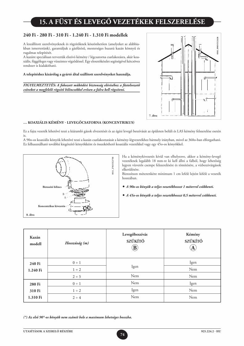
74925.224.2 - HUUTASÍTÁSOK A SZERELŐ RÉSZÉRE
0 ÷ 1
1 ÷ 2
2 ÷ 5
0 ÷ 1
1 ÷ 2
2 ÷ 4
15. A Füst és leVegő Vezetékek Felszerelése
240 Fi - 280 Fi - 310 Fi - 1.240 Fi - 1.310 Fi modellek
A leszállított szerelvényeknek és rögzítőknek köszönhetően (amelyeket az alábbia-kban ismertetünk), garantáljuk a gázfűtésű, mesterséges huzatú kazán könnyű és rugalmas telepítését.A kazánt speciálisan terveztük elszívó kémény / légcsatorna csatlakozásra, akár koa-xiális, függőleges vagy vízszintes végződéssel. Egy elosztókészlet segítségével kétcsöves rendszer is kialakítható.
A telepítéshez kizárólag a gyártó által szállított szerelvényeket használja.
FIGYELMEZTETÉS: A fokozott működési biztonság eléréséhez a füstelvezető csöveket a megfelelő rögzítő bilincsekkel erősen a falra kell rögzíteni.
7. ábra
8. ábra
… koAxiális kéMény - leVegőCsAtornA (konCentrikus)
Ez a fajta vezeték lehetővé teszi a kiáramló gázok elvezetését és az égési levegő beszívását az épületen belüli és LAS kémény felszerelése esetén is.A 90o-os koaxiális könyök lehetővé teszi a kazán csatlakoztatását a kémény-légvezetékhez bármely irányban, mivel az 360o-ban elforgatható. Ez felhasználható továbbá kiegészítő könyökként és összeköthető koaxiális vezetékkel vagy egy 45o-os könyökkel.
0511
_270
1/C
g17
50
Ha a kéménykivezetés kívül van elhelyezve, akkor a kémény-levegő vezetéknek legalább 18 mm-re ki kell állni a falból, hogy lehetőség legyen vízvetős csempe felszerelésére és tömítésére, a vízbeszivárgások elkerülésére.Biztosítson méterenként minimum 1 cm lefelé lejtést kifelé a vezeték hosszában.
• A 90o-os könyök a teljes vezetékhosszt 1 méterrel csökkenti.
• A 45o-os könyök a teljes vezetékhosszt 0,5 méterrel csökkenti.
biztosító bilincs
koncentrikus kivezetés
AB
(*) Az első 90°-os könyök nem számít bele a maximum lehetséges hosszba.
kazán
modell
240 Fi
1.240 Fi
280 Fi
310 Fi
1.310 Fi
Hosszúság (m)
levegőbeszívás
szűkítő
b
Igen
Nem
Nem
Igen
Nem
kémény
szűkítő
A
Igen
Nem
Nem
Igen
Nem
Nem
0503
_090
5/C
g16
38
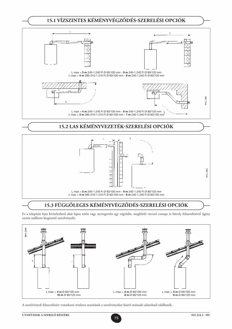
75925.224.2 - HUUTASÍTÁSOK A SZERELŐ RÉSZÉRE
L max = 2 m Ø 60/100 mm 8 m Ø 80/120 mm
L max = 4 m Ø 60/100 mm 10 m Ø 80/120 mm
15.1 Vízszintes kéMényVégzőDés-szerelési opCiók
15.2 lAs kéMényVezeték-szerelési opCiók
15.3 Függőleges kéMényVégzőDés-szerelési opCiók
Ez a telepítési fajta kivitelezhető akár lapos tetőn vagy nyeregtetőn egy végződés, megfelelő vízvető csempe és hüvely felszerelésével (igény esetén szállított kiegészítő szerelvények).
0512
_200
105
12_2
002
A szerelvények felszerelésére vonatkozó részletes utasítások a szerelvényeket kísérő műszaki adatoknál találhatók.
0611
_210
1
L max = 3 m Ø 60/100 mm 9 m Ø 80/120 mm
L max = 5 m 240-1.240 Fi Ø 60/100 mm - 9 m 240-1.240 Fi Ø 80/120 mmL max = 4 m 280-310-1.310 Fi Ø 60/100 mm - 8 m 240-1.240 Fi Ø 80/120 mm
L max = 4 m 240-1.240 Fi Ø 60/100 mm - 8 m 240-1.240 Fi Ø 80/120 mmL max = 3 m 280-310-1.310 Fi Ø 60/100 mm - 7 m 240-1.240 Fi Ø 80/120 mm
L max = 5 m 240-1.240 Fi Ø 60/100 mm - 9 m 240-1.240 Fi Ø 80/120 mmL max = 4 m 280-310-1.310 Fi Ø 60/100 mm - 8 m 240-1.240 Fi Ø 80/120 mm
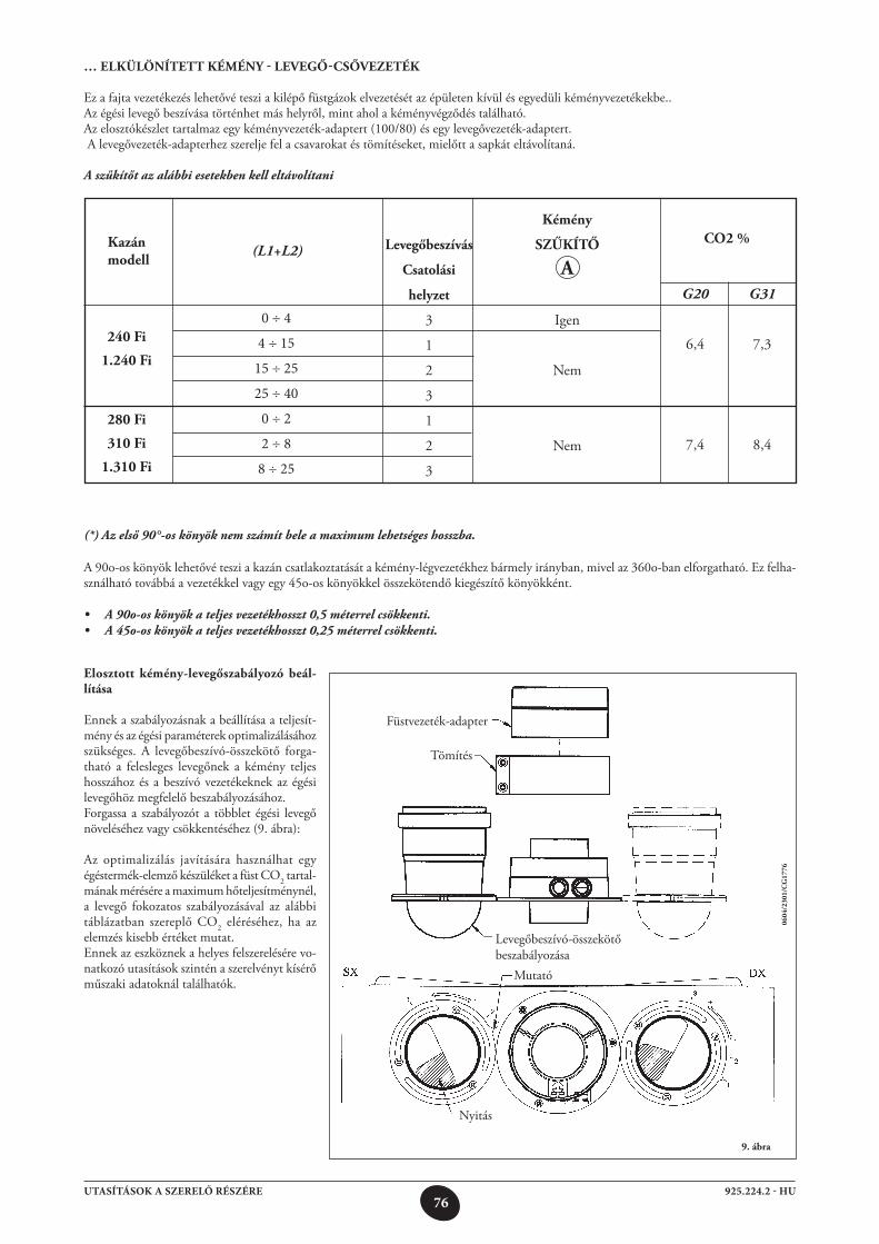
76925.224.2 - HUUTASÍTÁSOK A SZERELŐ RÉSZÉRE
… elkülönített kéMény - leVegő-CsőVezeték
Ez a fajta vezetékezés lehetővé teszi a kilépő füstgázok elvezetését az épületen kívül és egyedüli kéményvezetékekbe..Az égési levegő beszívása történhet más helyről, mint ahol a kéményvégződés található.Az elosztókészlet tartalmaz egy kéményvezeték-adaptert (100/80) és egy levegővezeték-adaptert. A levegővezeték-adapterhez szerelje fel a csavarokat és tömítéseket, mielőtt a sapkát eltávolítaná.
A szűkítőt az alábbi esetekben kell eltávolítani
9. ábra
A 90o-os könyök lehetővé teszi a kazán csatlakoztatását a kémény-légvezetékhez bármely irányban, mivel az 360o-ban elforgatható. Ez felha-sználható továbbá a vezetékkel vagy egy 45o-os könyökkel összekötendő kiegészítő könyökként.
• A 90o-os könyök a teljes vezetékhosszt 0,5 méterrel csökkenti.• A 45o-os könyök a teljes vezetékhosszt 0,25 méterrel csökkenti.
0604
/230
1/C
g17
76
(*) Az első 90°-os könyök nem számít bele a maximum lehetséges hosszba.
elosztott kémény-levegőszabályozó beál-lítása
Ennek a szabályozásnak a beállítása a teljesít-mény és az égési paraméterek optimalizálásához szükséges. A levegőbeszívó-összekötő forga-tható a felesleges levegőnek a kémény teljes hosszához és a beszívó vezetékeknek az égési levegőhöz megfelelő beszabályozásához.Forgassa a szabályozót a többlet égési levegő növeléséhez vagy csökkentéséhez (9. ábra):
Az optimalizálás javítására használhat egy égéstermék-elemző készüléket a füst CO2 tartal-mának mérésére a maximum hőteljesítménynél, a levegő fokozatos szabályozásával az alábbi táblázatban szereplő CO2 eléréséhez, ha az elemzés kisebb értéket mutat.Ennek az eszköznek a helyes felszerelésére vo-natkozó utasítások szintén a szerelvényt kísérő műszaki adatoknál találhatók.
Füstvezeték-adapter
Tömítés
Levegőbeszívó-összekötő beszabályozása
Mutató
Nyitás
kazán modell
240 Fi
1.240 Fi
280 Fi
310 Fi
1.310 Fi
(L1+L2) levegőbeszívás
Csatolási
helyzet
3
1
2
3
1
2
3
kémény
szűkítő
A
Igen
Nem
Nem
Co2 %
G20
6,4
7,4
G31
7,3
8,4
0 ÷ 4
4 ÷ 15
15 ÷ 25
25 ÷ 40
0 ÷ 2
2 ÷ 8
8 ÷ 25
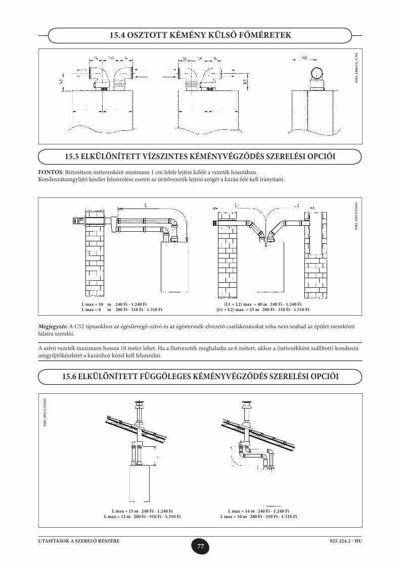
77925.224.2 - HUUTASÍTÁSOK A SZERELŐ RÉSZÉRE
0503
_220
1/C
G16
43
15.5 ELKÜLÖNÍTETT VÍZSZINTES KÉMÉNYVÉGZŐDÉS SZERELÉSI OPCIÓI
FONTOS: Biztosítson méterenként minimum 1 cm lefelé lejtést kifelé a vezeték hosszában. Kondenzátumgyűjtő készlet felszerelése esetén az ürítővezeték lejtési szögét a kazán felé kell irányítani.
Megjegyzés: A C52 típusokhoz az égésilevegő-szívó és az égéstermék-elvezető csatlakozásokat soha nem szabad az épület szemköztifalaira szerelni.
A szívó vezeték maximum hossza 10 méter lehet. Ha a füstvezeték meghaladja az 6 métert, akkor a (tartozékként szállított) kondenzá umgyűjtőkészletet a kazánhoz közel kell felszerelni.
15.4 OSZTOTT KÉMÉNY KÜLSŐ FŐMÉRETEK
0504
_180
6/C
G_1
794
0503
_091
1/C
G16
44
15.6 ELKÜLÖNÍTETT FÜGGŐLEGES KÉMÉNYVÉGZŐDÉS SZERELÉSI OPCIÓI
(L1 + L2) max = 40 m 240 Fi - 1.240 Fi(L1 + L2) max = 25 m 280 Fi - 310 Fi - 1.310 Fi
L max = 10 m 240 Fi - 1.240 FiL max = 8 m 280 Fi - 310 Fi - 1.310 Fi
L max = 15 m 240 Fi - 1.240 FiL max = 12 m 280 Fi - 310 Fi - 1.310 Fi
L max = 14 m 240 Fi - 1.240 Fi L max = 10 m 280 Fi - 310 Fi - 1.310 Fi
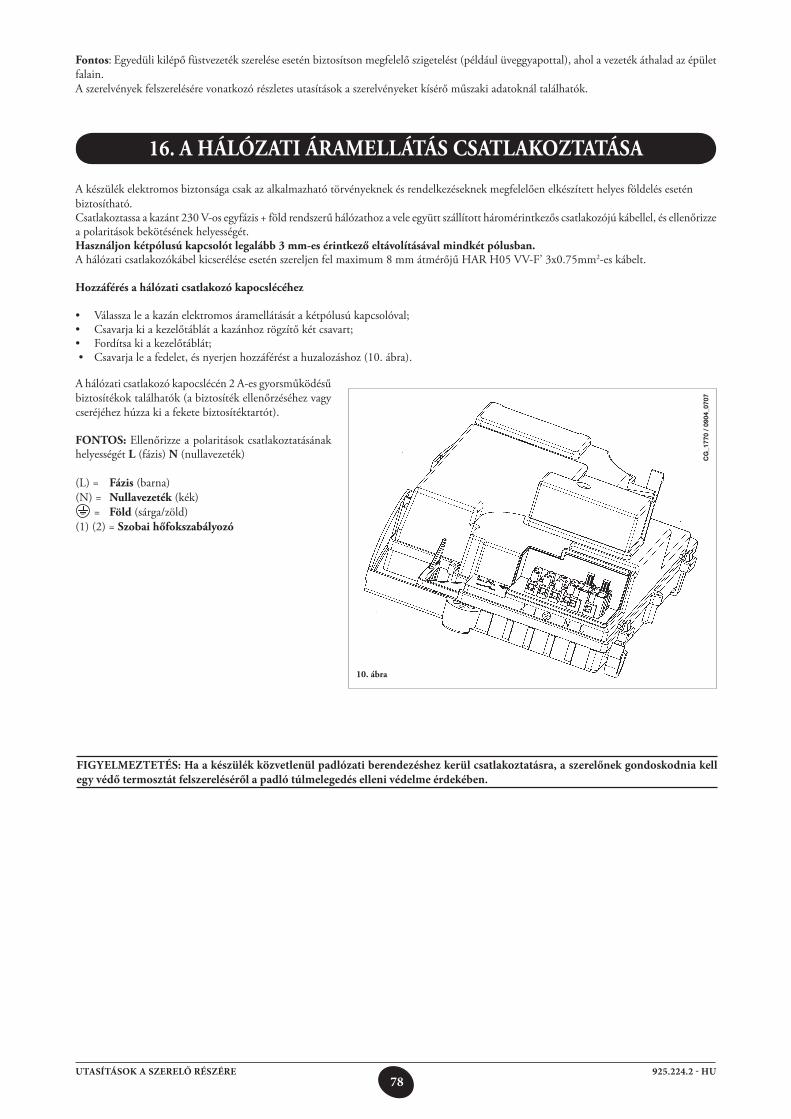
78925.224.2 - HUUTASÍTÁSOK A SZERELŐ RÉSZÉRE
16. A hálózAti árAMellátás CsAtlAkoztAtásA
A készülék elektromos biztonsága csak az alkalmazható törvényeknek és rendelkezéseknek megfelelően elkészített helyes földelés esetén biztosítható.Csatlakoztassa a kazánt 230 V-os egyfázis + föld rendszerű hálózathoz a vele együtt szállított háromérintkezős csatlakozójú kábellel, és ellenőrizze a polaritások bekötésének helyességét.használjon kétpólusú kapcsolót legalább 3 mm-es érintkező eltávolításával mindkét pólusban.A hálózati csatlakozókábel kicserélése esetén szereljen fel maximum 8 mm átmérőjű HAR H05 VV-F’ 3x0.75mm2-es kábelt.
hozzáférés a hálózati csatlakozó kapocslécéhez
• Válasszaleakazánelektromosáramellátásátakétpólusúkapcsolóval;• Csavarjakiakezelőtáblátakazánhozrögzítőkétcsavart;• Fordítsakiakezelőtáblát; • Csavarjaleafedelet,ésnyerjenhozzáféréstahuzalozáshoz(10.ábra).
10. ábra
A hálózati csatlakozó kapocslécén 2 A-es gyorsműködésű biztosítékok találhatók (a biztosíték ellenőrzéséhez vagy cseréjéhez húzza ki a fekete biztosítéktartót).
Fontos: Ellenőrizze a polaritások csatlakoztatásának helyességét l (fázis) n (nullavezeték)
(L) = Fázis (barna)(N) = nullavezeték (kék) = Föld (sárga/zöld)(1) (2) = szobai hőfokszabályozó
Fontos: Egyedüli kilépő füstvezeték szerelése esetén biztosítson megfelelő szigetelést (például üveggyapottal), ahol a vezeték áthalad az épület falain.A szerelvények felszerelésére vonatkozó részletes utasítások a szerelvényeket kísérő műszaki adatoknál találhatók.
FIGYELMEZTETÉS: Ha a készülék közvetlenül padlózati berendezéshez kerül csatlakoztatásra, a szerelőnek gondoskodnia kell egy védő termosztát felszereléséről a padló túlmelegedés elleni védelme érdekében.
CG
_177
0 /
0904
_070
7
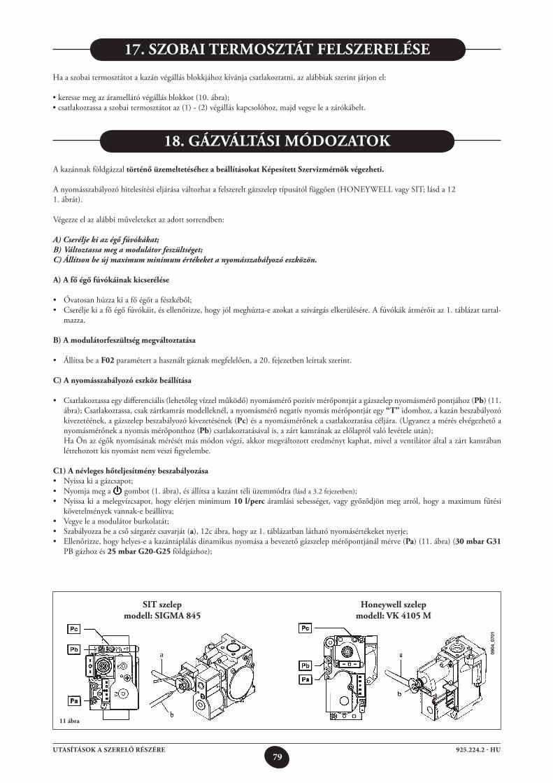
79925.224.2 - HUUTASÍTÁSOK A SZERELŐ RÉSZÉRE
sit szelepmodell: sigMA 845
honeywell szelepmodell: Vk 4105 M
17. szobAi terMosztát Felszerelése
Ha a szobai termosztátot a kazán végállás blokkjához kívánja csatlakoztatni, az alábbiak szerint járjon el:
•keressemegazáramellátóvégállásblokkot(10.ábra);•csatlakoztassaaszobaitermosztátotaz(1)-(2)végálláskapcsolóhoz,majdvegyeleazárókábelt.
A kazánnak földgázzal történő üzemeltetéséhez a beállításokat képesített szervizmérnök végezheti.
A nyomásszabályozó hitelesítési eljárása változhat a felszerelt gázszelep típusától függően (HONEY WELL vagy SIT; lásd a 121. ábrát).
Végezze el az alábbi műveleteket az adott sorrendben:
A) Cserélje ki az égő fúvókákat;B) Változtassa meg a modulátor feszültséget;C) Állítson be új maximum minimum értékeket a nyomásszabályozó eszközön.
A) A fő égő fúvókáinak kicserélése
• Óvatosanhúzzakiafőégőtafészkéből;• Cseréljekiafőégőfúvókáit,ésellenőrizze,hogyjólmeghúzta-eazokataszivárgáselkerülésére.Afúvókákátmérőitaz1.táblázattartal-
mazza.
b) A modulátorfeszültség megváltoztatása
• ÁllítsabeaF02 paramétert a használt gáznak megfelelően, a 20. fejezetben leírtak szerint.
C) A nyomásszabályozó eszköz beállítása
• Csatlakoztassaegydifferenciális(lehetőlegvízzelműködő)nyomásmérőpozitívmérőpontjátagázszelepnyomásmérőpontjához(pb) (11. ábra); Csatlakoztassa, csak zártkamrás modelleknél, a nyomásmérő negatív nyomás mérőpontját egy “t” idomhoz, a kazán beszabályozó kivezetéének, a gázszelep beszabályozó kivezetésének (pc) és a nyomásmérőnek a csatlakoztatása céljára. (Ugyanez a mérés elvégezhető a nyomásmérőnek a nyomás mérőponthoz (pb) csatlakoztatásával is, a zárt kamrának az előlapról való levétele után);
Ha Ön az égők nyomásának mérését más módon végzi, akkor megváltozott eredményt kaphat, mivel a ventilátor által a zárt kamrában létrehozott kis nyomást nem veszi figyelembe.
C1) A névleges hőteljesítmény beszabályozása• Nyissakiagázcsapot;• Nyomjamega gombot (1. ábra), és állítsa a kazánt téli üzemmódra (lásd a 3.2 fejezetben); • Nyissakiamelegvízcsapot,hogyelérjenminimum10 l/perc áramlási sebességet, vagy győződjön meg arról, hogy a maximum fűtési
követelmények vannak-e beállítva;• Vegyeleamodulátorburkolatát;• Szabályozzabeacsősárgarézcsavarját(a), 12c ábra, hogy az 1. táblázatban látható nyomásértékeket nyerje;• Ellenőrizze,hogyhelyes-eakazántáplálásdinamikusnyomásaabevezetőgázszelepmérőpontjánálmérve(pa) (11. ábra) (30 mbar g31
PB gázhoz és 25 mbar g20-g25 földgázhoz);
18. gázVáltási MóDozAtok
11 ábra
0904
_070
1
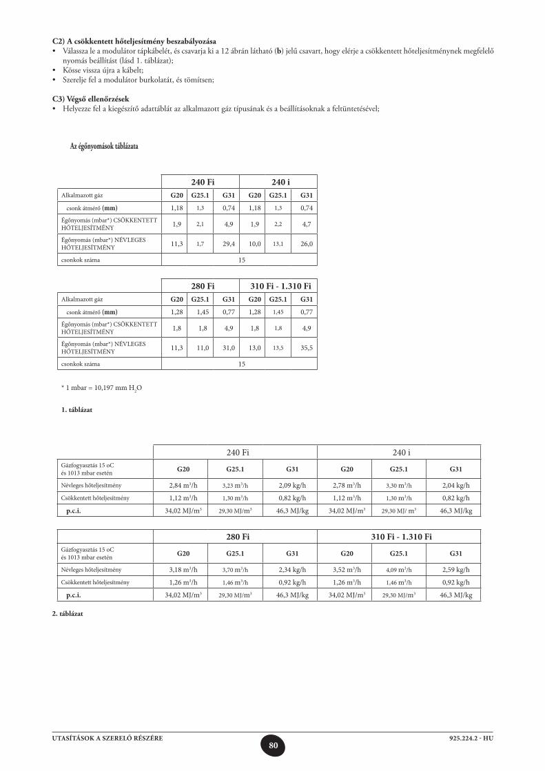
80925.224.2 - HUUTASÍTÁSOK A SZERELŐ RÉSZÉRE
C2) A csökkentett hőteljesítmény beszabályozása• Válasszaleamodulátortápkábelét,éscsavarjakia12ábránlátható(b) jelű csavart, hogy elérje a csökkentett hőteljesítménynek megfelelő
nyomás beállítást (lásd 1. táblázat);• Kössevisszaújraakábelt;• Szereljefelamodulátorburkolatát,éstömítsen;
C3) Végső ellenőrzések• Helyezzefelakiegészítőadattáblátazalkalmazottgáztípusánakésabeállításoknakafeltüntetésével;
Az égőnyomások táblázata
240 Fi 240 iAlkalmazott gáz G20 G25.1 G31 G20 G25.1 G31
csonk átmérő (mm) 1,18 1,3 0,74 1,18 1,3 0,74
Égőnyomás (mbar*) CSÖKKENTETT HŐTELJESÍTMÉNY 1,9 2,1 4,9 1,9 2,2 4,7
Égőnyomás (mbar*) NÉVLEGES HŐTELJESÍTMÉNY 11,3 1,7 29,4 10,0 13,1 26,0
csonkok száma 15
280 Fi 310 Fi - 1.310 FiAlkalmazott gáz G20 G25.1 G31 G20 G25.1 G31
csonk átmérő (mm) 1,28 1,45 0,77 1,28 1,45 0,77
Égőnyomás (mbar*) CSÖKKENTETT HŐTELJESÍTMÉNY 1,8 1,8 4,9 1,8 1,8 4,9
Égőnyomás (mbar*) NÉVLEGES HŐTELJESÍTMÉNY 11,3 11,0 31,0 13,0 13,5 35,5
csonkok száma 15
* 1 mbar = 10,197 mm H2O
1. táblázat
240 Fi 240 iGázfogyasztás 15 oC és 1013 mbar esetén G20 G25.1 G31 G20 G25.1 G31
Névleges hőteljesítmény 2,84 m3/h 3,23 m3/h 2,09 kg/h 2,78 m3/h 3,30 m3/h 2,04 kg/h
Csökkentett hőteljesítmény 1,12 m3/h 1,30 m3/h 0,82 kg/h 1,12 m3/h 1,30 m3/h 0,82 kg/h
p.c.i. 34,02 MJ/m3 29,30 MJ/m3 46,3 MJ/kg 34,02 MJ/m3 29,30 MJ/ m3 46,3 MJ/kg
280 Fi 310 Fi - 1.310 FiGázfogyasztás 15 oC és 1013 mbar esetén G20 G25.1 G31 G20 G25.1 G31
Névleges hőteljesítmény 3,18 m3/h 3,70 m3/h 2,34 kg/h 3,52 m3/h 4,09 m3/h 2,59 kg/h
Csökkentett hőteljesítmény 1,26 m3/h 1,46 m3/h 0,92 kg/h 1,26 m3/h 1,46 m3/h 0,92 kg/h
p.c.i. 34,02 MJ/m3 29,30 MJ/m3 46,3 MJ/kg 34,02 MJ/m3 29,30 MJ/m3 46,3 MJ/kg
2. táblázat
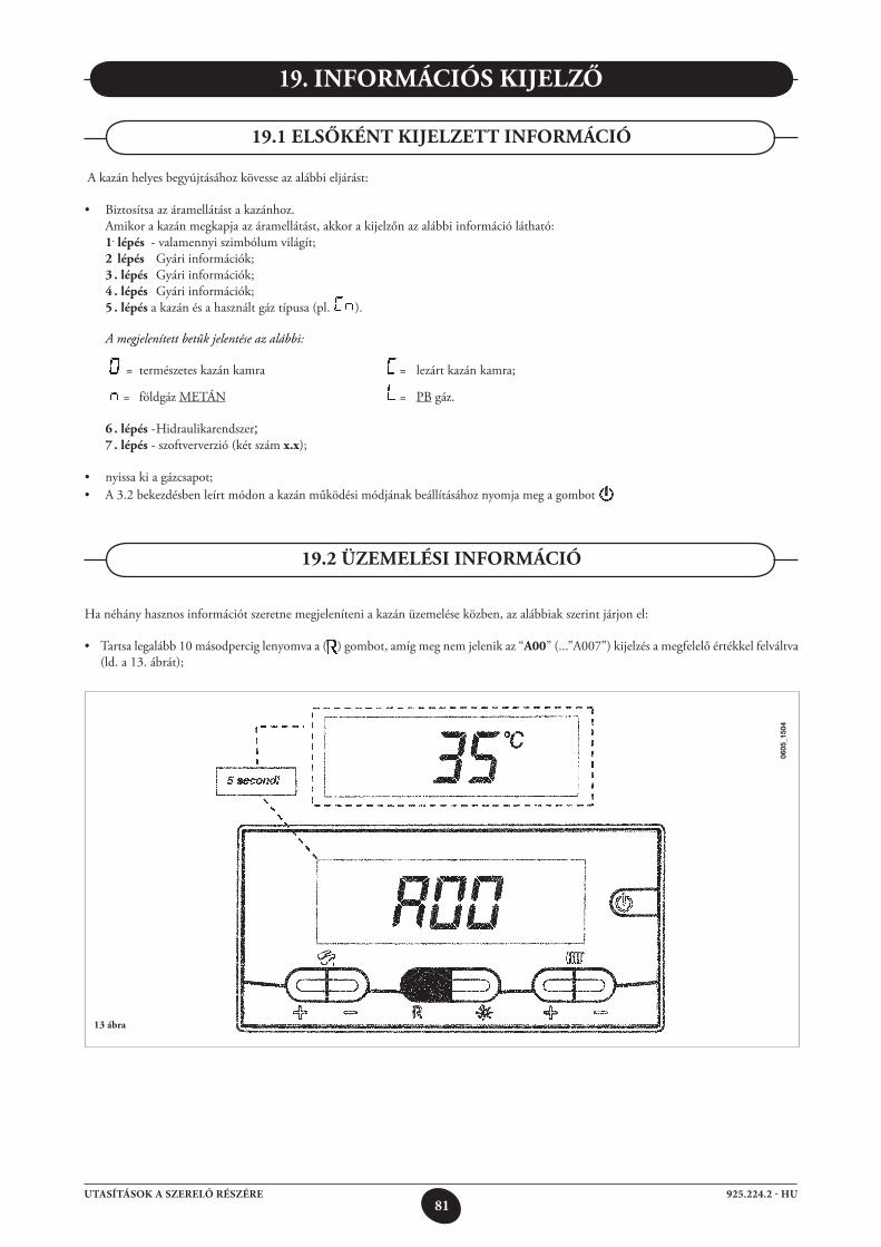
81925.224.2 - HUUTASÍTÁSOK A SZERELŐ RÉSZÉRE
19. inForMáCiós kijelző
19.2 üzeMelési inForMáCió
A kazán helyes begyújtásához kövesse az alábbi eljárást:
• Biztosítsaazáramellátástakazánhoz. Amikor a kazán megkapja az áramellátást, akkor a kijelzőn az alábbi információ látható: 1. lépés - valamennyi szimbólum világít; 2 lépés Gyári információk; 3 . lépés Gyári információk; 4 . lépés Gyári információk; 5 . lépés a kazán és a használt gáz típusa (pl. ). A megjelenített betűk jelentése az alábbi:
= természetes kazán kamra = lezárt kazán kamra;
= földgáz METÁN = PB gáz.
6 . lépés - Hidraulikarendszer; 7 . lépés - szoftververzió (két szám x.x);
• nyissakiagázcsapot;• A3.2 bekezdésben leírt módon a kazán működési módjának beállításához nyomja meg a gombot
19.1 elsőként kijelzett inForMáCió
Ha néhány hasznos információt szeretne megjeleníteni a kazán üzemelése közben, az alábbiak szerint járjon el:
• Tartsalegalább10másodperciglenyomvaa( ) gombot, amíg meg nem jelenik az “A00” (...”A007”) kijelzés a megfelelő értékkel felváltva (ld. a 13. ábrát);
13 ábra
0605
_150
4
82925.224.2 - HUUTASÍTÁSOK A SZERELŐ RÉSZÉRE
A műszaki információk teljessé tételéhez olvassa el a “SERVICE UTASÍTÁSOK” dokumentumot is.
19.4 KIEGÉSZÍTŐ INFORMÁCIÓK
•Aháztartásimelegvíz+/- gombját lenyomva jelenítse meg az alábbi pillanatnyi információkat:
A00: háztartási melegvíz hőmérsékleti értéke (°C); A01: külső hőmérséklet (csatlakoztatott külső szondaérzékelővel);A02: modulátor jelenlegi értéke (100% = 230 mA METÁN - 100% = 310 mA GPL); A03: teljesítmény szint értéke (%; A04: hőmérséklet beállítás értéke (°C); A05: központi fűtés áramlati hőmérsékletének értéke (°C); A06: áramlási vízérték (10 kb. (l/min x 10); A07: lángjel érték (8-100%). Megjegyzés: az A08 és az A09-es sor nincs használatban.
•Ezafunkció3másodpercigmaradbekapcsolva.Hakiszeretnelépnibelőle,a3.2.pontalattleírtakszerintnyomjalea gombot.
Megjegyzés: Az újraindítást mindössze 5 egymást követő alkalommal lehet megpróbálni, ezt követően a RESET funkció kikapcsolódik, a gázkazán pedig zárlat alá kerül. Egy újabb RESET (újraindítási) kísérletnél az alábbiak szerint járjon el:•legalább2másodpercigtartsalenyomvaa gombot; •amikorakazánta gomb legalább 2 másodperces lenyomva tartásával indítja újra, a kijelzőn az “OFF” (kikapcsolás) felirat jelenik meg;.•legalább2másodpercigtartsalenyomvaa gombot a 3.2. pont alatt leírtaknak megfelelően.
A hibakódok és a rendellenességek ismertetését lásd a 9. fejezetben.
19.3 renDellenességek kijelzése
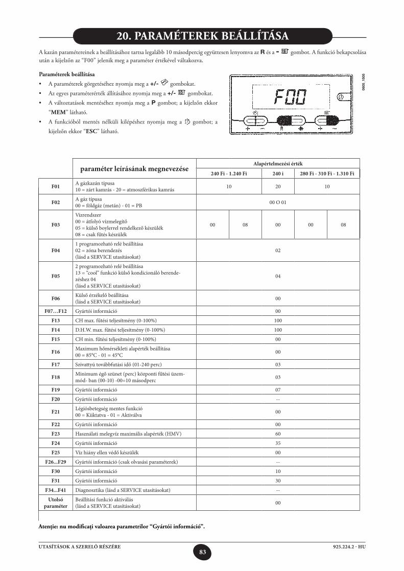
83925.224.2 - HUUTASÍTÁSOK A SZERELŐ RÉSZÉRE
paraméter leírásának megnevezéseAlapértelmezési érték
240 Fi - 1.240 Fi 240 i 280 Fi - 310 Fi - 1.310 Fi
F01 A gázkazán típusa10 = zárt kamrás - 20 = atmoszférikus kamrás 10 20 10
F02 A gáz típusa00 = földgáz (metán) - 01 = PB 00 O 01
F03
Vízrendszer00 = átfolyó vízmelegítő05 = külső boylerrel rendelkező készülék08 = csak fűtés készülék
00 08 00 00 08
F041 programozható relé beállítása02 = zóna berendezés(lásd a SERVICE utasításokat)
02
F05
2 programozható relé beállítása13 = “cool” funkció külső kondicionáló berende- zéshez 04(lásd a SERVICE utasításokat)
04
F06 Külső érzékelő beállítása(lásd a SERVICE utasításokat) 00
F07…F12 Gyártói információ 00
F13 CH max. fűtési teljesítmény (0-100%) 100
F14 D.H.W. max. fűtési teljesítmény (0-100%) 100
F15 CH min. fűtési teljesítmény (0-100%) 00
F16 Maximum hőmérsékleti alapérték beállítása00 = 85°C - 01 = 45°C 00
F17 Szivattyú továbbfutási idő (01-240 perc) 03
F18 Minimum égő szünet (perc) központi fűtési üzem-mód- ban (00-10) -00=10 másodperc 03
F19 Gyártói információ 07
F20 Gyártói információ --
F21 Légiósbetegség mentes funkció00 = Kiiktatva - 01 = Aktiválva 00
F22 Gyártói információ 00
F23 Használati melegvíz maximális alapérték (HMV) 60
F24 Gyártói információ 35
F25 Víz hiány ellen védő készülék 00
F26...F29 Gyártói információ (csak olvasási paraméterek) --
F30 Gyártói információ 10
F31 Gyártói információ 30
F34...F41 Diagnosztika (lásd a SERVICE utasításokat) --
Utolsó paraméter
Beállítási funkció aktiválás(lásd a SERVICE utasításokat) 00
Atenţie: nu modificaţi valoarea parametrilor “gyártói információ”.
20. pArAMéterek beállításAA kazán paramétereinek a beállításához tartsa legalább 10 másodpercig együttesen lenyomva az R és a - gombot. A funkció bekapcsolása után a kijelzőn az “F00” jelenik meg a paraméter értékével váltakozva.
paraméterek beállítása
• Aparaméterekgörgetéséheznyomjamega +/- gombokat.• Azegyesparaméterértékállításáhoznyomjamega +/- gombokat.• Aváltoztatásokmentéséheznyomjamega P gombot; a kijelzőn ekkor
“MeM” látható.• A funkcióbólmentés nélküli kilépéshez nyomjameg a gombot; a
kijelzőn ekkor “esC” látható.
0605
_150
5
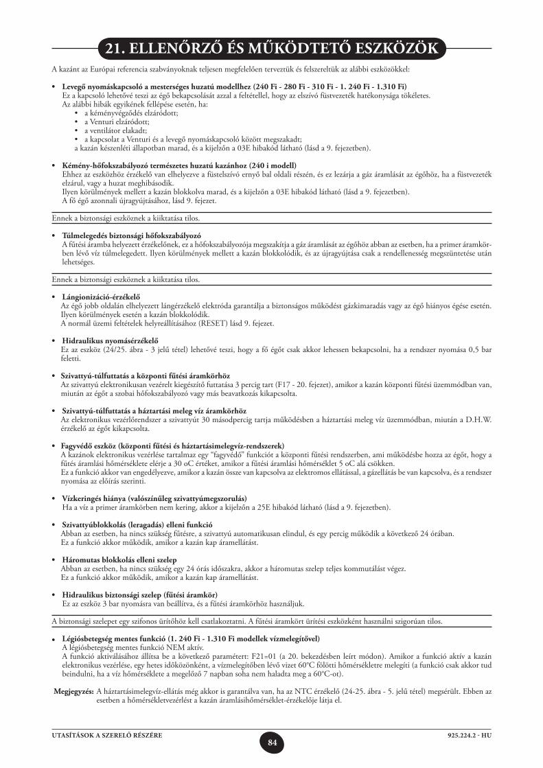
84925.224.2 - HUUTASÍTÁSOK A SZERELŐ RÉSZÉRE
A kazánt az Európai referencia szabványoknak teljesen megfelelően terveztük és felszereltük az alábbi eszközökkel:
• Levegőnyomáskapcsolóamesterségeshuzatúmodellhez(240Fi-280Fi-310Fi-1.240Fi-1.310Fi) Ez a kapcsoló lehetővé teszi az égő bekapcsolását azzal a feltétellel, hogy az elszívó füstvezeték hatékonysága tökéletes. Az alábbi hibák egyikének fellépése esetén, ha: • akéményvégződéselzáródott; • aVenturielzáródott; • aventilátorelakadt; • akapcsolataVenturiésalevegőnyomáskapcsolóközöttmegszakadt; a kazán készenléti állapotban marad, és a kijelzőn a 03E hibakód látható (lásd a 9. fejezetben).
• Kémény-hőfokszabályozótermészeteshuzatúkazánhoz(240imodell) Ehhez az eszközhöz érzékelő van elhelyezve a füstelszívó ernyő bal oldali részén, és ez lezárja a gáz áramlását az égőhöz, ha a füstvezeték
elzárul, vagy a huzat meghibásodik. Ilyen körülmények mellett a kazán blokkolva marad, és a kijelzőn a 03E hibakód látható (lásd a 9. fejezetben). A fő égő azonnali újragyújtásához, lásd 9. fejezet.
Ennek a biztonsági eszköznek a kiiktatása tilos.
• Túlmelegedésbiztonságihőfokszabályozó A fűtési áramba helyezett érzékelőnek, ez a hőfokszabályozója megszakítja a gáz áramlását az égőhöz abban az esetben, ha a primer áramkör-
ben lévő víz túlmelegedett. Ilyen körülmények mellett a kazán blokkolódik, és az újragyújtása csak a rendellenesség megszüntetése után lehetséges.
Ennek a biztonsági eszköznek a kiiktatása tilos.
• Lángionizáció-érzékelő Az égő jobb oldalán elhelyezett lángérzékelő elektróda garantálja a biztonságos működést gázkimaradás vagy az égő hiányos égése esetén.
Ilyen körülmények esetén a kazán blokkolódik. A normál üzemi feltételek helyreállításához (RESET) lásd 9. fejezet.
• Hidraulikusnyomásérzékelő Ez az eszköz (24/25. ábra - 3 jelű tétel) lehetővé teszi, hogy a fő égőt csak akkor lehessen bekapcsolni, ha a rendszer nyomása 0,5 bar
feletti.
• Szivattyú-túlfuttatásaközpontifűtésiáramkörhöz Az szivattyú elektronikusan vezérelt kiegészítő futtatása 3 percig tart (F17 - 20. fejezet), amikor a kazán központi fűtési üzemmódban van,
miután az égőt a szobai hőfokszabályozó vagy más beavatkozás kikapcsolta.
• Szivattyú-túlfuttatásaháztartásimelegvízáramkörhöz Az elektronikus vezérlőrendszer a szivattyút 30 másodpercig tartja működésben a háztartási meleg víz üzemmódban, miután a D.H.W.
érzékelő az égőt kikapcsolta.
• Fagyvédőeszköz(központifűtésiésháztartásimelegvíz-rendszerek) A kazánok elektronikus vezérlése tartalmaz egy “fagyvédő” funkciót a központi fűtési rendszerben, ami működésbe hozza az égőt, hogy a
fűtés áramlási hőmérséklete elérje a 30 oC értéket, amikor a fűtési áramlási hőmérséklet 5 oC alá csökken. Ez a funkció akkor van engedélyezve, amikor a kazán össze van kapcsolva az elektromos ellátással, a gázellátás be van kapcsolva, és a rendszer
nyomása az előírás szerinti.
• Vízkeringéshiánya(valószínűlegszivattyúmegszorulás) Ha a víz a primer áramkörben nem kering, akkor a kijelzőn a 25E hibakód látható (lásd a 9. fejezetben).
• Szivattyúblokkolás(leragadás)ellenifunkció Abban az esetben, ha nincs szükség fűtésre, a szivattyú automatikusan elindul, és egy percig működik a következő 24 órában. Ez a funkció akkor működik, amikor a kazán kap áramellátást.
• Háromutasblokkoláselleniszelep Abban az esetben, ha nincs szükség egy 24 órás időszakra, akkor a háromutas szelep teljes kommutálást végez. Ez a funkció akkor működik, amikor a kazán kap áramellátást.
• Hidraulikusbiztonságiszelep(fűtésiáramkör) Ez az eszköz 3 bar nyomásra van beállítva, és a fűtési áramkörhöz használjuk.
A biztonsági szelepet egy szifonos ürítőhöz kell csatlakoztatni. A fűtési áramkört ürítési eszközként használni szigorúan tilos.
• Légiósbetegségmentesfunkció(1.240Fi-1.310Fimodellekvízmelegítővel) A légiósbetegség mentes funkció NEM aktív. A funkció aktiválásához állítsa be a következő paramétert: F21=01 (a 20. bekezdésben leírt módon). Amikor a funkció aktív a kazán
elektronikus vezérlése, egy hetes időközönként, a vízmelegítőben lévő vizet 60°C fölötti hőmérsékletre melegíti (a funkció csak akkor tud beindulni, ha a víz hőmérséklete a megelőző 7 napban soha nem haladta meg a 60°C-ot).
Megjegyzés: A háztartásimelegvíz-ellátás még akkor is garantálva van, ha az NTC érzékelő (24-25. ábra - 5. jelű tétel) megsérült. Ebben az esetben a hőmérsékletvezérlést a kazán áramlásihőmérséklet-érzékelője látja el.
21. ellenőrző és MűköDtető eszközök
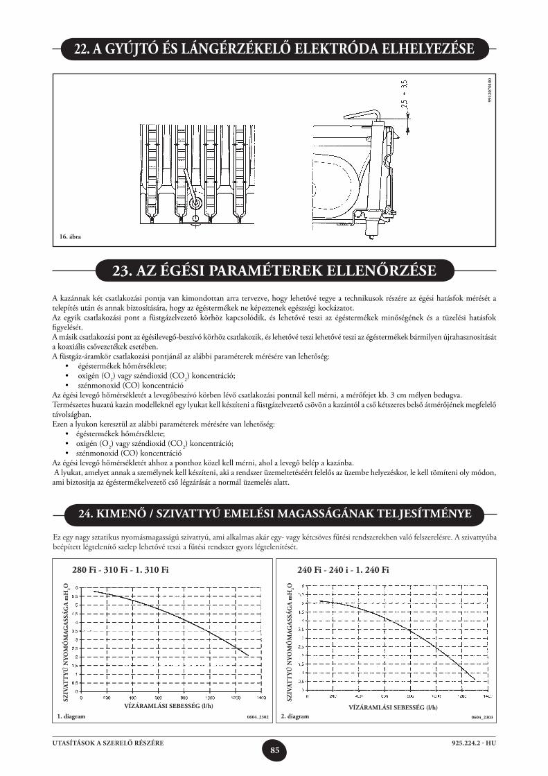
85925.224.2 - HUUTASÍTÁSOK A SZERELŐ RÉSZÉRE
22. A gyÚjtó és lángérzékelő elektróDA elhelyezése
16. ábra
9912
0701
00
A kazánnak két csatlakozási pontja van kimondottan arra tervezve, hogy lehetővé tegye a technikusok részére az égési hatásfok mérését a telepítés után és annak biztosítására, hogy az égéstermékek ne képezzenek egészségi kockázatot.Az egyik csatlakozási pont a füstgázelvezető körhöz kapcsolódik, és lehetővé teszi az égéstermékek minőségének és a tüzelési hatásfok figyelését.A másik csatlakozási pont az égésilevegő-beszívó körhöz csatlakozik, és lehetővé teszi lehetővé teszi az égéstermékek bármilyen újrahasznosítását a koaxiális csővezetékek esetében.A füstgáz-áramkör csatlakozási pontjánál az alábbi paraméterek mérésére van lehetőség: • égéstermékekhőmérséklete; • oxigén(O2) vagy széndioxid (CO2) koncentráció; • szénmonoxid(CO)koncentrációAz égési levegő hőmérsékletét a levegőbeszívó körben lévő csatlakozási pontnál kell mérni, a mérőfejet kb. 3 cm mélyen bedugva.Természetes huzatú kazán modelleknél egy lyukat kell készíteni a füstgázelvezető csövön a kazántól a cső kétszeres belső átmérőjének megfelelő távolságban.Ezen a lyukon keresztül az alábbi paraméterek mérésére van lehetőség: • égéstermékekhőmérséklete; • oxigén(O2) vagy széndioxid (CO2) koncentráció; • szénmonoxid(CO)koncentrációAz égési levegő hőmérsékletét ahhoz a ponthoz közel kell mérni, ahol a levegő belép a kazánba. A lyukat, amelyet annak a személynek kell készíteni, aki a rendszer üzemeltetéséért felelős az üzembe helyezéskor, le kell tömíteni oly módon, ami biztosítja az égéstermékelvezető cső légzárását a normál üzemelés alatt.
23. Az égési pArAMéterek ellenőrzése
Ez egy nagy sztatikus nyomásmagasságú szivattyú, ami alkalmas akár egy- vagy kétcsöves fűtési rendszerekben való felszerelésre. A szivattyúba beépített légtelenítő szelep lehetővé teszi a fűtési rendszer gyors légtelenítését.
1. diagram
24. kiMenő / sziVAttyÚ eMelési MAgAsságánAk teljesítMénye
VízárAMlási sebesség(l/h)
sziV
Att
yÚ n
yoM
óM
Ag
Ass
ág
A m
h2o
0604_2302 2. diagramVízárAMlási sebesség(l/h)
sziV
Att
yÚ n
yoM
óM
Ag
Ass
ág
A m
h2o
0604_2303
280 Fi - 310 Fi - 1. 310 Fi 240 Fi - 240 i - 1. 240 Fi
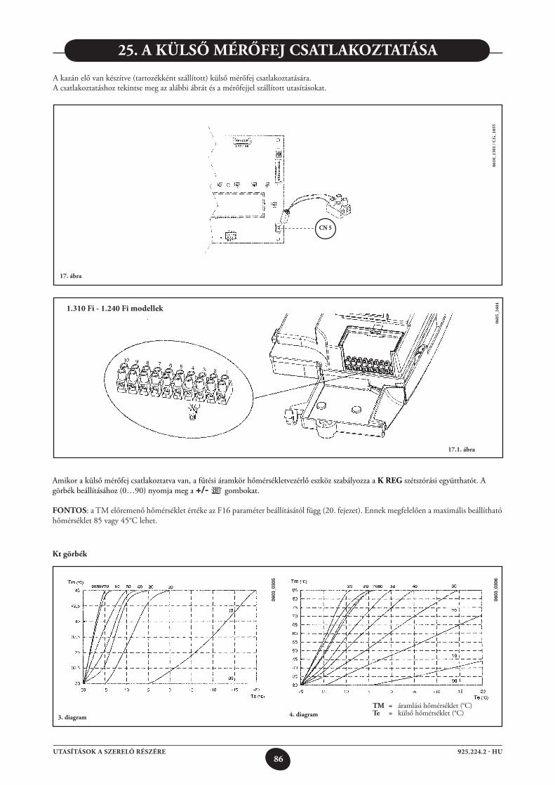
86925.224.2 - HUUTASÍTÁSOK A SZERELŐ RÉSZÉRE
0610
_130
1 / C
G_1
855
CN 5
0605
_160
4
17.1. ábra
1.310 Fi - 1.240 Fi modellek
25. A külső MérőFej CsAtlAkoztAtásA
A kazán elő van készítve (tartozékként szállított) külső mérőfej csatlakoztatására.A csatlakoztatáshoz tekintse meg az alábbi ábrát és a mérőfejjel szállított utasításokat.
17. ábra
Amikor a külső mérőfej csatlakoztatva van, a fűtési áramkör hőmérsékletvezérlő eszköz szabályozza a k reg szétszórási együtthatót. A görbék beállításához (0…90) nyomja meg a +/- gombokat.
Fontos: a TM előremenő hőmérséklet értéke az F16 paraméter beállításától függ (20. fejezet). Ennek megfelelően a maximális beállítható hőmérséklet 85 vagy 45°C lehet.
kt görbék
3. diagram
tM = áramlási hőmérséklet (°C) te = külső hőmérséklet (°C)
0603
_030
5
0603
_030
6
4. diagram
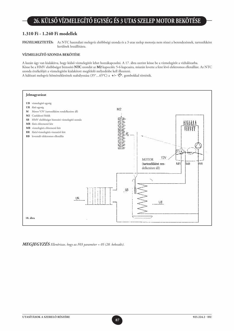
87925.224.2 - HUUTASÍTÁSOK A SZERELŐ RÉSZÉRE
MOTOR(tartozékként ren-tartozékként ren-delkezésre áll)
18. ábra
1.310 Fi - 1.240 Fi modellek
FigyelMeztetés: Az NTC használati melegvíz elsőbbségi szonda és a 3 utas szelep motorja nem részei a berendezésnek, tartozékként kerülnek leszállításra.
VízMelegítő szonDA bekötése
A kazán úgy van kialakítva, hogy külső vízmelegítőt lehet hozzákapcsolni. A 17. ábra szerint kösse be a vízmelegítőt a vízhálózatba.Kösse be a HMV elsőbbséget biztosító ntC szondát az M2 kapocsléc 5-6 kapcsaira, miután levette a fent lévő elektromos ellenállást. Az NTC szonda érzékelőjét a vízmelegítőn kialakított megfelelő mélyedésbe kell illeszteni. A hálózati melegvíz hőmérsékletének szabályozása (35°....65°C) a +/- . gombokkal történik.
26. külső VízMelegítő egység és 3 utAs szelep Motor bekötése
jelmagyarázat
ub vízmelegítő egységur fűtő egységM Motor V3V (tartozékként rendelkezésre áll)M2 Csatlakozó blokksb HMV elsőbbséget biztosító vízmelegítő szondaMr fűtés előremenő körMb vízmelegítés előremenő körrr fűtés/vízmelegítés visszatérő körrb leveendő elektromos ellenállás
MEGJEGYZÉS Ellenőrizze, hogy az F03 paraméter = 05 (20. bekezdés).
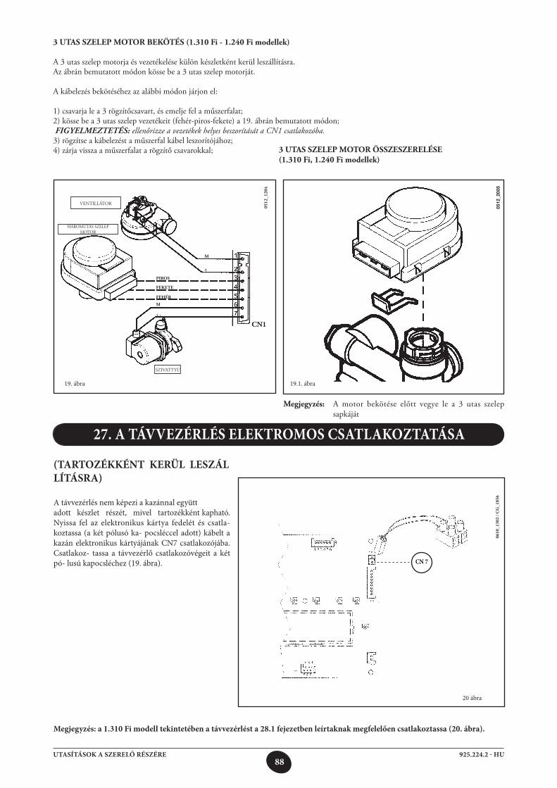
88925.224.2 - HUUTASÍTÁSOK A SZERELŐ RÉSZÉRE
(TARTOZÉKKÉNT KERÜL LESZÁLLÍTÁSRA)
A távvezérlés nem képezi a kazánnal együttadott készlet részét, mivel tartozékként kapható. Nyissa fel az elektronikus kártya fedelét és csatla-koztassa (a két pólusó ka- pocsléccel adott) kábelt a kazán elektronikus kártyájának CN7 csatlakozójába. Csatlakoz- tassa a távvezérlő csatlakozóvégeit a két pó- lusú kapocsléchez (19. ábra).
27. A TÁVVEZÉRLÉS ELEKTROMOS CSATLAKOZTATÁSA
20 ábra
Megjegyzés: a 1.310 Fi modell tekintetében a távvezérlést a 28.1 fejezetben leírtaknak megfelelően csatlakoztassa (20. ábra).
0610
_130
2 / C
G_1
856
CN 7
3UTASSZELEPMOTORBEKÖTÉS(1.310 Fi - 1.240 Fi modellek)
A 3 utas szelep motorja és vezetékelése külön készletként kerül leszállításra.Az ábrán bemutatott módon kösse be a 3 utas szelep motorját.
A kábelezés bekötéséhez az alábbi módon járjon el:
1) csavarja le a 3 rögzítőcsavart, és emelje fel a műszerfalat;2) kösse be a 3 utas szelep vezetékeit (fehér-piros-fekete) a 19. ábrán bemutatott módon; FIGYELMEZTETÉS: ellenőrizze a vezetékek helyes beszorítását a CN1 csatlakozóba.3) rögzítse a kábelezést a műszerfal kábel leszorítójához;4) zárja vissza a műszerfalat a rögzítő csavarokkal; 3 utAs szelep Motor összeszerelése
(1.310 Fi, 1.240 Fi modellek)
0512
_200
5
0512
_120
4
VENTILLÁTOR
HÁROMUTAS SZELEP MOTOR
SZIVATTYÚ
Fehér
piros
Fekete
M
4.c.
M
4
Cn1
Megjegyzés: A motor bekötése előtt vegye le a 3 utas szelep sapkáját
19. ábra 19.1. ábra
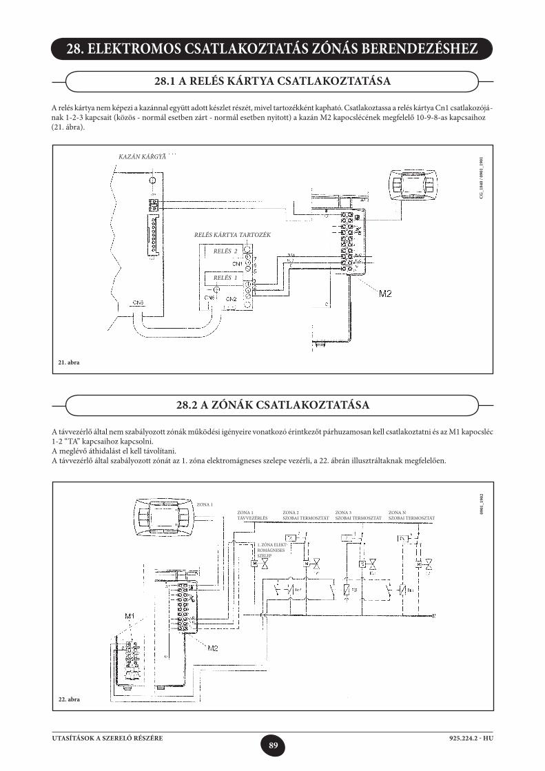
89925.224.2 - HUUTASÍTÁSOK A SZERELŐ RÉSZÉRE
28. ELEKTROMOS CSATLAKOZTATÁS ZÓNÁS BERENDEZÉSHEZ
A relés kártya nem képezi a kazánnal együtt adott készlet részét, mivel tartozékként kapható. Csatlakoztassa a relés kártya Cn1 csatlakozójá-nak 1-2-3 kapcsait (közös - normál esetben zárt - normál esetben nyitott) a kazán M2 kapocslécének megfelelő 10-9-8-as kapcsaihoz(21. ábra).
28.1 A RELÉS KÁRTYA CSATLAKOZTATÁSA
Kazán Kárgya
rELÉS KárTya TarTOzÉK
rELÉS 2
rELÉS 1
CG
_184
0 / 0
901_
1901
21. abra
A távvezérlő által nem szabályozott zónák működési igényeire vonatkozó érintkezőt párhuzamosan kell csatlakoztatni és az M1 kapocsléc 1-2 “TA” kapcsaihoz kapcsolni.A meglévő áthidalást el kell távolítani.A távvezérlő által szabályozott zónát az 1. zóna elektromágneses szelepe vezérli, a 22. ábrán illusztráltaknak megfelelően.
28.2 A ZÓNÁK CSATLAKOZTATÁSA
ZONA 1
ZONA 1 TÁVVEZÉRLÉS
0901
_190
2
22. abra
1. ZÓNA ELEKT-ROMÁGNESES SZELEP
ZONA 2 SZOBAI TERMOSZTÁT
ZONA 3 SZOBAI TERMOSZTÁT
ZONA N SZOBAI TERMOSZTÁT
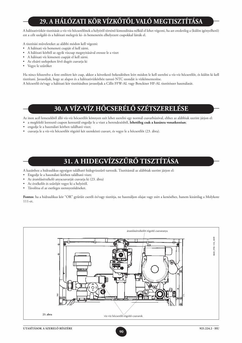
90925.224.2 - HUUTASÍTÁSOK A SZERELŐ RÉSZÉRE
0610
_270
1 / C
G_1
839
23. abra víz-víz hőcserélő rögzítő-csavarok
áramlásérzékelőt rögzítő csavaranya
A hálózativízkör tisztítását a víz-víz hőcserélőnek a helyéről történő kimozdítása nélkül el lehet végezni, ha azt eredetileg a (külön igényelhető) ezt a célt szolgáló és a hálózati melegvíz ki- és bemenetén elhelyezett csapokkal látták el.
A tisztítási műveleteket az alábbi módon kell végezni:• Ahálózativízbemeneticsapjátelkellzárni.• Ahálózatikörbőlazegyikvízcsapmegnyitásávaleresszeleavizet• Ahálózativízkimeneticsapjátelkellzárni.• Azelzárószelepekenlévődugótcsavarjaki• Vegyeleszűrőket
Ha nincs felszerelve a fent említett két csap, akkor a következő bekezdésben leírt módon le kell szerelni a víz-víz hőcserélőt, és külön ki kell tisztítani. Javasoljuk, hogy az alapot és a hálózativízkörhöz tarozó NTC szondát is vízkőmentesítse.A hőcserélő és/vagy a hálózati kör tisztításához javasoljuk a Cillit FFW-AL vagy Benckiser HF-AL tisztítószer használatát.
29. A hálózAti kör Vízkőtől VAló MegtisztításA
Az inox acél lemezekből álló víz-víz hőcserélőt könnyen szét lehet szerelni egy normál csavarhúzóval, ehhez az alábbiak szerint járjon el:• amegfelelőleeresztőcsaponkeresztülengedjeleavizetaberendezésből,lehetőleg csak a kazánra vonatkozóan;• engedjeleahasználatikörbentalálhatóvizet;• csavarjaleavíz-vízhőcserélőtrögzítőkétszemközticsavart,ésvegyeleahőcserélőt(23.ábra).
30. A Víz-Víz hőCserélő szétszerelése
A kazánhoz a hidraulikus egységen található hidegvízszűrő tartozik. Tisztításnál az alábbiak szerint járjon el:• Engedjeleahasználatikörbentalálhatóvizet;• Azáramlásérzékelőanyacsavarjátcsavarjaki(23.ábra)• Azérzékelőtésszűrőjétvegyekiahelyéről.• Távolítsaelazesetlegesszennyeződéseket.
Fontos: ha a hidraulikus kör “OR” gyűrűit cseréli és/vagy tisztítja, ne használjon olajat vagy zsírt a kenéséhez, hanem kizárólag a Molykote 111-et.
31. A hiDegVízszűrő tisztításA
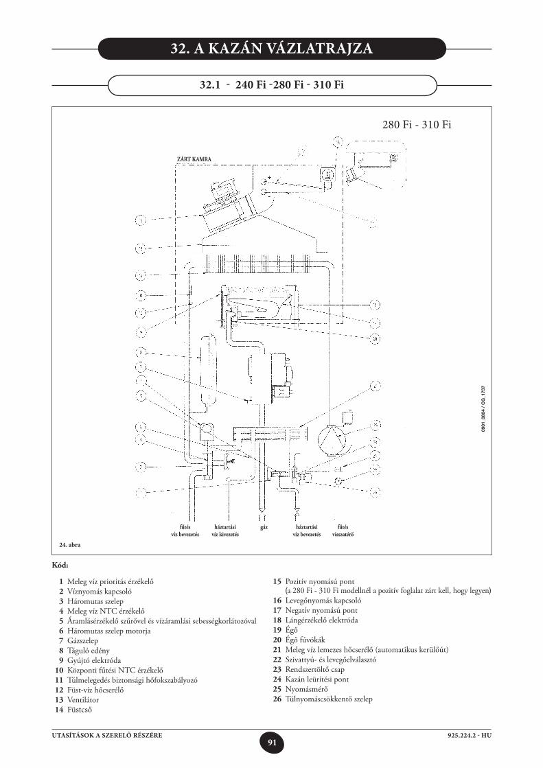
91925.224.2 - HUUTASÍTÁSOK A SZERELŐ RÉSZÉRE
24. abra
32. A KAZÁN VÁZLATRAJZA
280 Fi - 310 Fi
kód:
1 Meleg víz prioritás érzékelő 2 Víznyomás kapcsoló 3 Háromutas szelep 4 Meleg víz NTC érzékelő 5 Áramlásérzékelő szűrővel és vízáramlási sebességkorlátozóval 6 Háromutas szelep motorja 7 Gázszelep 8 Táguló edény 9 Gyújtó elektróda 10 Központi fűtési NTC érzékelő 11 Túlmelegedés biztonsági hőfokszabályozó 12 Füst-víz hőcserélő 13 Ventilátor 14 Füstcső
fűtés háztartási gáz háztartási fűtés víz bevezetés víz kivezetés víz bevezetés visszatérő
15 Pozitív nyomású pont (a 280 Fi - 310 Fi modellnél a pozitív foglalat zárt kell, hogy legyen) 16 Levegőnyomás kapcsoló 17 Negatív nyomású pont 18 Lángérzékelő elektróda 19 Égő 20 Égő fúvókák 21 Meleg víz lemezes hőcserélő (automatikus kerülőút) 22 Szivattyú- és levegőelválasztó 23 Rendszertöltő csap 24 Kazán leürítési pont 25 Nyomásmérő 26 Túlnyomáscsökkentő szelep
zárt kAMrA
0901
_080
4 /
CG
_173
7
32.1 - 240 Fi -280 Fi - 310 Fi
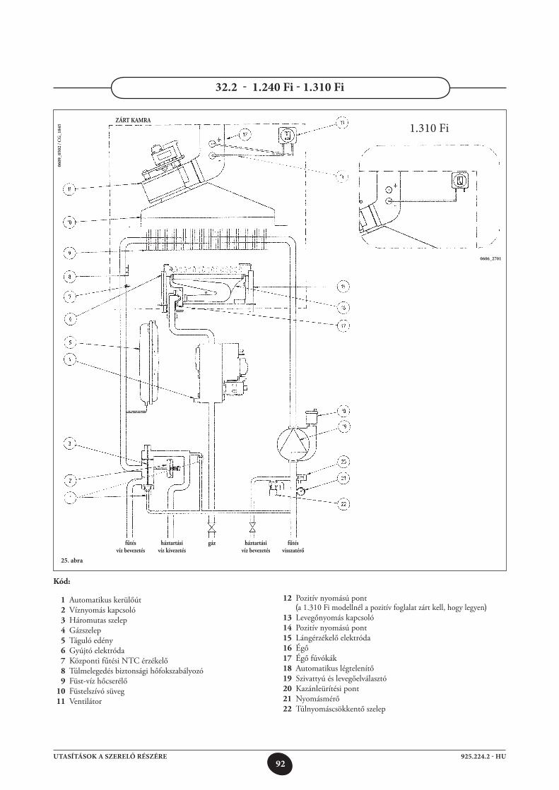
92925.224.2 - HUUTASÍTÁSOK A SZERELŐ RÉSZÉRE
25. abra
0609
_050
2 / C
G_1
845
32.2 - 1.240 Fi - 1.310 Fi
zárt kAMrA
0606_2701
1.310 Fi
fűtés háztartási gáz háztartási fűtés víz bevezetés víz kivezetés víz bevezetés visszatérő
kód:
1 Automatikus kerülőút 2 Víznyomás kapcsoló 3 Háromutas szelep 4 Gázszelep 5 Táguló edény 6 Gyújtó elektróda 7 Központi fűtési NTC érzékelő 8 Túlmelegedés biztonsági hőfokszabályozó 9 Füst-víz hőcserélő 10 Füstelszívó süveg 11 Ventilátor
12 Pozitív nyomású pont (a 1.310 Fi modellnél a pozitív foglalat zárt kell, hogy legyen) 13 Levegőnyomás kapcsoló 14 Pozitív nyomású pont 15 Lángérzékelő elektróda 16 Égő 17 Égő fúvókák 18 Automatikus légtelenítő 19 Szivattyú és levegőelválasztó 20 Kazánleürítési pont 21 Nyomásmérő 22 Túlnyomáscsökkentő szelep
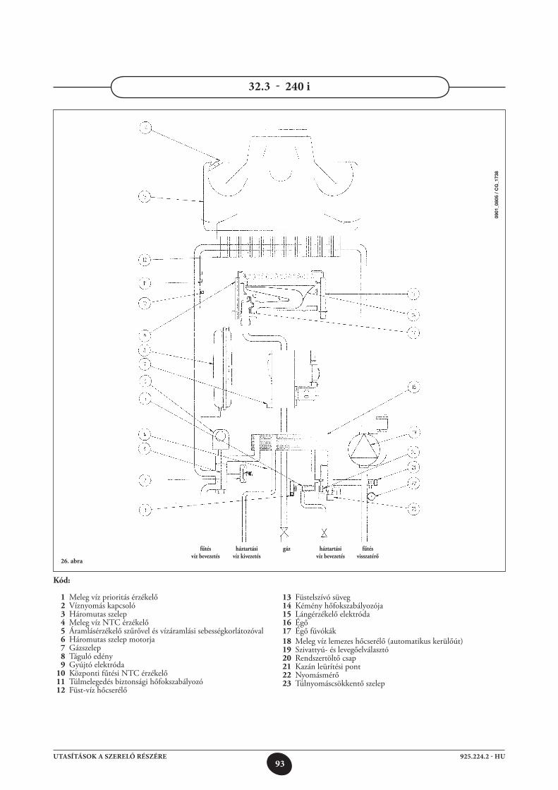
93925.224.2 - HUUTASÍTÁSOK A SZERELŐ RÉSZÉRE
32.3 - 240 i
26. abra
kód:
1 Meleg víz prioritás érzékelő 2 Víznyomás kapcsoló 3 Háromutas szelep 4 Meleg víz NTC érzékelő 5 Áramlásérzékelő szűrővel és vízáramlási sebességkorlátozóval 6 Háromutas szelep motorja 7 Gázszelep 8 Táguló edény 9 Gyújtó elektróda 10 Központi fűtési NTC érzékelő 11 Túlmelegedés biztonsági hőfokszabályozó 12 Füst-víz hőcserélő
13 Füstelszívó süveg 14 Kémény hőfokszabályozója 15 Lángérzékelő elektróda 16 Égő 17 Égő fúvókák 18 Meleg víz lemezes hőcserélő (automatikus kerülőút) 19 Szivattyú- és levegőelválasztó 20 Rendszertöltő csap 21 Kazán leürítési pont 22 Nyomásmérő 23 Túlnyomáscsökkentő szelep
fűtés háztartási gáz háztartási fűtés víz bevezetés víz kivezetés víz bevezetés visszatérő
0901
_080
5 /
CG
_173
8
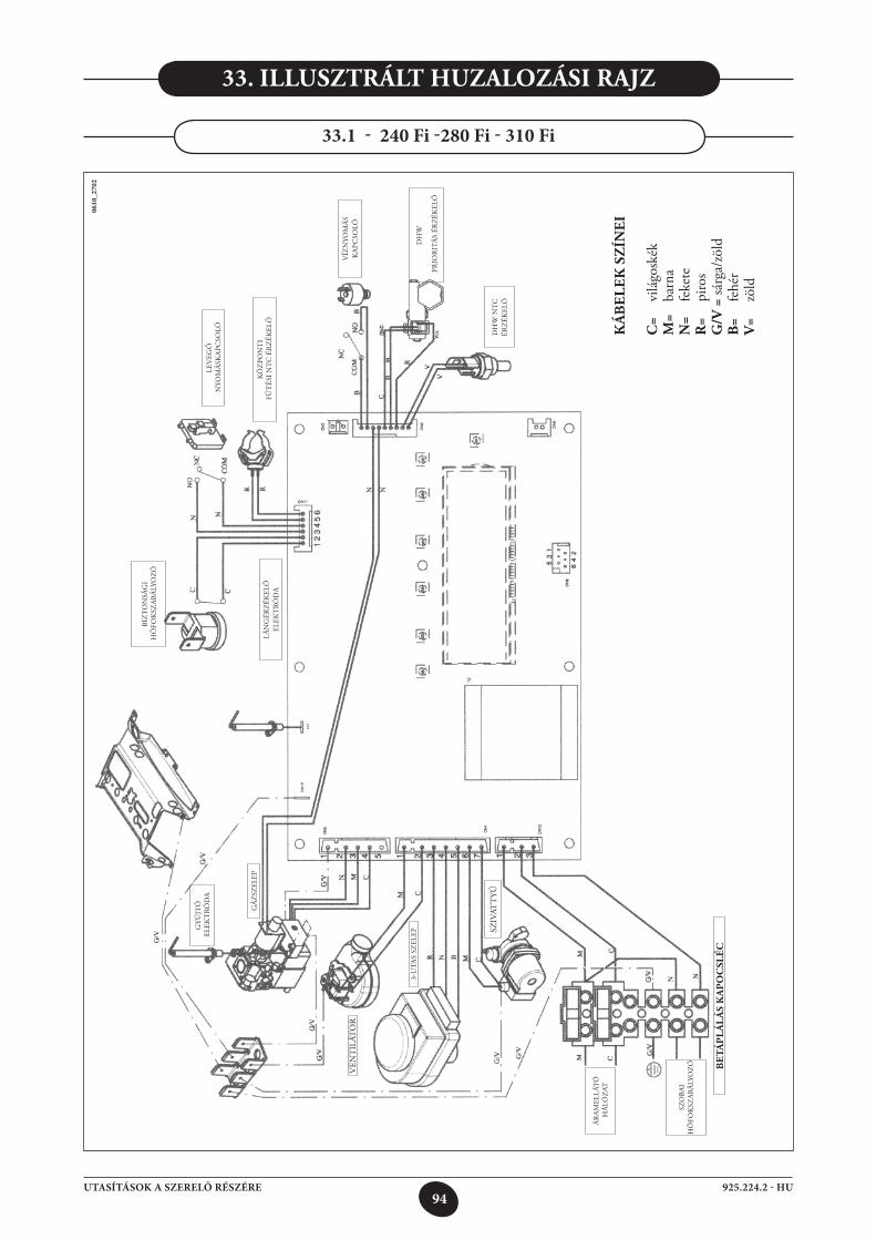
94925.224.2 - HUUTASÍTÁSOK A SZERELŐ RÉSZÉRE
33. illusztrált huzAlozási rAjz
33.1 - 240 Fi -280 Fi - 310 Fi
0610
_270
2
VEN
TIL
ÁTO
R
ÁR
AM
ELLÁ
TÓ
HÁ
LÓZ
AT
BIZ
TO
NSÁ
GI
Hő
FOK
SZA
BÁLY
OZÓ
GYÚ
JTÓ
ELE
KT
RÓD
A
3-U
TAS
SZEL
EP
KÖ
ZPO
NT
I F
űT
ÉSI N
TC
ÉR
ZÉK
ELő
LEV
EGő
NYO
MÁ
SKA
PCSO
LÓ
SZO
BAI
Hő
FOK
SZA
BÁLY
OZÓ
LÁN
GÉR
ZÉK
ELő
EL
EKT
RÓD
A
VÍZ
NYO
MÁ
S K
APC
SOLÓ
DH
W
PRIO
RIT
ÁS
ÉRZ
ÉKEL
ő
SZIV
ATT
YÚD
HW
NT
C
ÉRZ
ÉKEL
ő
be
táp
lá
lá
s k
Ap
oC
slé
C
GÁZ
SZEL
EP
ká
be
lek
sz
íne
i
C=
vilá
gosk
ékM
= ba
rna
n=
feke
ter
= pi
ros
g/V
= sá
rga/
zöld
b=
fehé
rV
= zö
ld
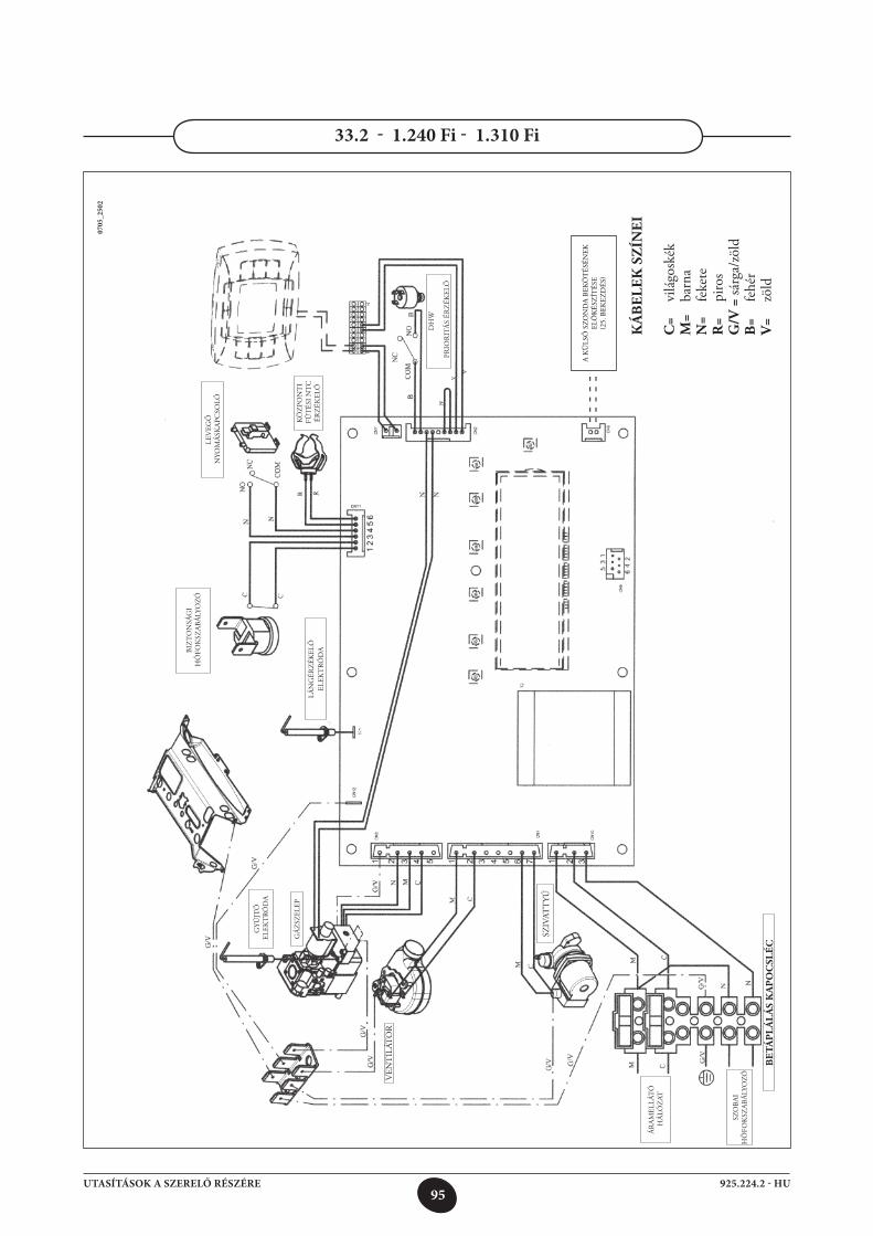
95925.224.2 - HUUTASÍTÁSOK A SZERELŐ RÉSZÉRE
33.2 - 1.240 Fi - 1.310 Fi
0705
_250
2
ká
be
lek
sz
íne
i
C=
vilá
gosk
ékM
= ba
rna
n=
feke
ter
= pi
ros
g/V
= sá
rga/
zöld
b=
fehé
rV
= zö
ld
VEN
TIL
ÁTO
R
ÁR
AM
ELLÁ
TÓ
HÁ
LÓZ
AT
BIZ
TO
NSÁ
GI
Hő
FOK
SZA
BÁLY
OZÓ
GYÚ
JTÓ
ELE
KT
RÓD
A
KÖ
ZPO
NT
I F
űT
ÉSI N
TC
ÉR
ZÉK
ELő
LEV
EGő
NYO
MÁ
SKA
PCSO
LÓ
SZO
BAI
Hő
FOK
SZA
BÁLY
OZÓ
LÁN
GÉR
ZÉK
ELő
EL
EKT
RÓD
A
DH
W
PRIO
RIT
ÁS
ÉRZ
ÉKEL
ő
SZIV
ATT
YÚ
be
táp
lá
lá
s k
Ap
oC
slé
C
GÁZ
SZEL
EP
- - -
- -- -
- - -
A K
ÜLS
ő S
ZON
DA
BEK
ÖT
ÉSÉN
EK
ELő
KÉS
ZÍT
ÉSE
(25.
BEK
EZD
ÉS)
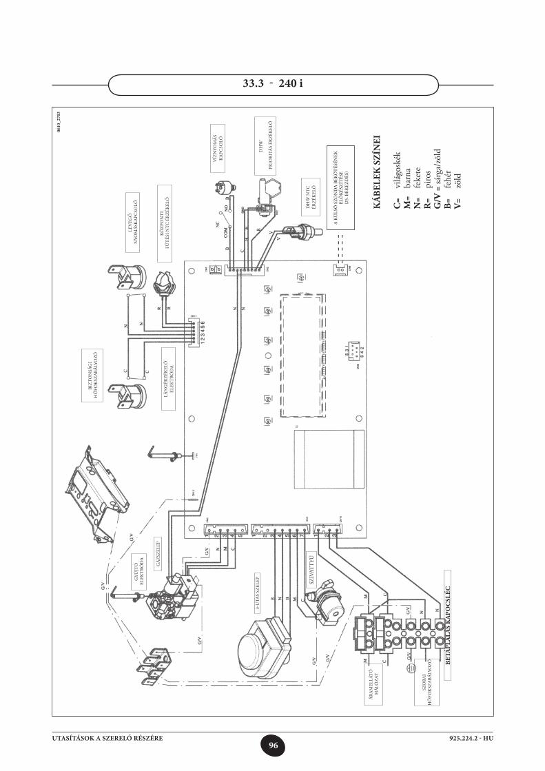
96925.224.2 - HUUTASÍTÁSOK A SZERELŐ RÉSZÉRE
33.3 - 240 i
0610
_270
3
ÁR
AM
ELLÁ
TÓ
HÁ
LÓZ
AT
BIZ
TO
NSÁ
GI
Hő
FOK
SZA
BÁLY
OZÓ
GYÚ
JTÓ
ELE
KT
RÓD
A
3-U
TAS
SZEL
EP
KÖ
ZPO
NT
I F
űT
ÉSI N
TC
ÉR
ZÉK
ELő
LEV
EGő
NYO
MÁ
SKA
PCSO
LÓ
SZO
BAI
Hő
FOK
SZA
BÁLY
OZÓ
LÁN
GÉR
ZÉK
ELő
EL
EKT
RÓD
A
VÍZ
NYO
MÁ
S K
APC
SOLÓ
DH
W
PRIO
RIT
ÁS
ÉRZ
ÉKEL
ő
SZIV
ATT
YÚD
HW
NT
C
ÉRZ
ÉKEL
ő
be
táp
lá
lá
s k
Ap
oC
slé
C
GÁZ
SZEL
EP
ká
be
lek
sz
íne
i
C=
vilá
gosk
ékM
= ba
rna
n=
feke
ter
= pi
ros
g/V
= sá
rga/
zöld
b=
fehé
rV
= zö
ld
- - -
- -- -
- - -
A K
ÜLS
ő S
ZON
DA
BEK
ÖT
ÉSÉN
EK
ELő
KÉS
ZÍT
ÉSE
(25.
BEK
EZD
ÉS)
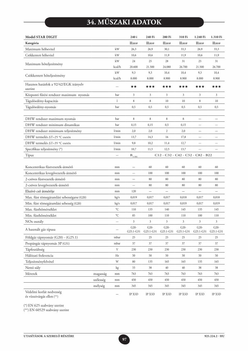
97925.224.2 - HUUTASÍTÁSOK A SZERELŐ RÉSZÉRE
34. MűszAki ADAtok
Model STAR DIGIT 240 i 240 Fi 280 Fi 310 Fi 1.240 Fi 1.310 Fi
kategória II2H3P II2H3P II2H3P II2H3P II2H3P II2H3P
Maximum hőbevitel kW 26,3 26,9 30,1 33,3 26,9 33,3
Csökkentett hőbevitel kW 10,6 10,6 11,9 11,9 10,6 11,9
Maximum hőteljesítmény kW 24 25 28 31 25 31
kcal/h 20.600 21.500 24.080 26.700 21.500 26.700
Csökkentett hőteljesítmény kW 9,3 9,3 10,4 10,4 9,3 10,4
kcal/h 8.000 8.000 8.900 8.900 8.000 8.900
Hasznos hatásfok a 92/42/EGK irányelv szerint
— ★★ ★★★ ★★★ ★★★ ★★★ ★★★
Központi fűtési rendszer maximum nyomás bar 3 3 3 3 3 3
Tágulóedény-kapacitás l 8 8 10 10 8 10
Tágulóedény-nyomás bar 0,5 0,5 0,5 0,5 0,5 0,5
DHW rendszer maximum nyomás bar 8 8 8 8 — —
DHW rendszer minimum dinamikus bar 0,15 0,15 0,5 0,15 — —
DHW rendszer minimum teljesítmény l/min 2,0 2,0 2 2,0 — —
DHW termelés ∆T=25 °C esetén l/min 13,7 14,3 16 17,8 — —
DHW termelés ∆T=35 °C esetén l/min 9,8 10,2 11,4 12,7 — —
Specifikus teljesítmény (*) l/min 10,7 11,5 12,5 13,7 — —
Típus — B11BS C12 - C32 - C42 - C52 - C82 - B22
Koncentrikus füstvezeték-átmérő mm — 60 60 60 60 60
Koncentrikus levegővezeték-átmérő mm — 100 100 100 100 100
2-csöves füstvezeték-átmérő mm — 80 80 80 80 80
2-csöves levegővezeték-átmérő mm — 80 80 80 80 80
Elszívó cső átmérője mm 120 — — — — —
Max. füst tömegáramlási sebességarse (G20) kg/s 0,019 0,017 0,017 0,018 0,017 0,018
Min. füst tömegáramlási sebesség (G20) kg/s 0,017 0,017 0,017 0,019 0,017 0,019
Max. füsthőmérséklet °C 110 135 140 145 135 145
Min. füsthőmérséklet °C 85 100 110 110 100 110
NOx osztály — 3 3 3 3 3 3
A használt gáz típusa — G20-G25.1-G31
G20-G25.1-G31
G20-G25.1-G31
G20-G25.1-G31
G20-G25.1-G31
G20-G25.1-G31
Földgáz tápnyomás (G20) - (G25.1) mbar 25 25 25 25 25 25
Propángáz tápnyomás 3P (G31) mbar 37 37 37 37 37 37
Tápfeszültség V 230 230 230 230 230 230
Hálózati frekvencia Hz 50 50 50 50 50 50
Teljesítményfelvétel W 80 135 165 165 135 165
Nettó súly kg 33 38 40 40 38 38
Méretek magasság mm 763 763 763 763 763 763
szélesség mm 450 450 450 450 450 450
mélység mm 345 345 345 345 345 345
Védelmi korlát nedvesség és vízszivárgás ellen (**)
— IP X5D IP X5D IP X5D IP X5D IP X5D IP X5D
(*) EN 625 szabvány szerint (**) EN 60529 szabvány szerint

98925.224.2 - HUUTASÍTÁSOK A SZERELŐ RÉSZÉRE
99925.224.2 - HUUTASÍTÁSOK A SZERELŐ RÉSZÉRE
codice 925.224.2Ediz. 1 - 04/09