Embed Size (px)
Citation preview
Manual de montagem e de instruções (Tradução do manual de montagem e de instruções original)
BTS Dispositivo de comutação térmica sem contato Versão 11, 15-07-2020 3626-011500 pt-bra, classe de proteção 0: publicamente
Man
ual d
e m
onta
gem
e d
e in
stru
ções
/ver
são
11/3
626-
0115
00
pt/c
lass
e de
pro
teçã
o 0:
pub
licam
ente
/15-
07-2
020
2
BTS, Dispositivo de comutação térmica sem contato Contato
Contato
Voith Group St. Pöltener Str. 43 89522 Heidenheim, ALEMANHA Telefone: + 49 7951 32 1666 E-mail: [email protected] Internet: www.voith.com/fluid-couplings Caso tenha questões sobre o produto, entre em contato com o Serviço de apoio ao cliente da Voith, fornecendo o número de série (veja a placa de identificação).
3626-011500 pt-br Este documento descreve o estado técnico do produto no final da redação em 15-07-2020. Copyright © by J.M. Voith SE & Co. KG Este documento está protegido por direitos autorais. Não pode ser total ou parcialmente traduzido, reproduzido, nem mecânica nem eletronicamente, nem transmitido a terceiros sem a autorização escrita do editor.
Man
ual d
e m
onta
gem
e d
e in
stru
ções
/ver
são
11/3
626-
0115
00
pt/c
lass
e de
pro
teçã
o 0:
pub
licam
ente
/15-
07-2
020
3
BTS, Dispositivo de comutação térmica sem contato Índice
Índice 1 Aplicações, características do BTS 5
2 Funcionamento do BTS 6
2.1 Elemento lógico 7
2.2 Detector de proximidade 7
2.3 Dispositivo de leitura 7
2.4 Amplificador de isolamento 7
2.5 Interação dos componentes do BTS 8
3 Dados técnicos 9
3.1 Elemento lógico 9
3.2 Detector de proximidade, flange de fixação 10
3.3 Dispositivo de leitura e amplificador de isolamento 10 3.3.1 Dispositivo de leitura 10 3.3.2 Amplificador de isolamento 230 V CA 10 3.3.3 Amplificador de isolamento 20…30 V CC 10
4 Instruções de utilização 11
5 Segurança 13
5.1 Instruções de segurança 13 5.1.1 Estrutura das instruções de segurança 13 5.1.2 Definição dos sinais de segurança 14
5.2 Uso devido 14
5.3 Uso indevido 14
5.4 Indicações gerais de perigo 14
5.5 Perigos residuais 18
5.6 Atuação em caso de acidente 18
5.7 Informações relativas à operação 18
5.8 Qualificação do pessoal 19
5.9 Inspeção dos produtos 19
6 Instalação 20
6.1 Estado de entrega 20
6.2 Escopo de fornecimento 20
Man
ual d
e m
onta
gem
e d
e in
stru
ções
/ver
são
11/3
626-
0115
00
pt/c
lass
e de
pro
teçã
o 0:
pub
licam
ente
/15-
07-2
020
4
BTS, Dispositivo de comutação térmica sem contato Índice
6.3 Montagem – Elemento lógico e detector de proximidade 21
6.4 Montagem, conexão – Dispositivo de leitura, amplificador de isolamento 26
7 Indicações e ajuste do dispositivo de leitura 29
7.1 Indicações – Dispositivo de leitura 29
7.2 Ajuste – Dispositivo de leitura 30
8 Colocação em serviço 31
9 Manutenção, conservação 32
9.1 Limpeza exterior 34
10 Descarte 35
11 Falhas – Soluções, detecção de erros 36
12 Pedidos de informações, solicitação de um técnico e de peças de reposição 39
13 Informações sobre peças de reposição 40
13.1 Elementos lógicos 40
13.2 Detector de proximidade, flange de fixação 41
13.3 Dispositivo de leitura 41
13.4 Amplificador de isolamento 41
14 Anexo 42
14.1 Detector de proximidade NJ10-22-N-E93-Y106925 42
14.2 Detector de proximidade NJ10-22-N-E93-Y30627 43
14.3 Detector de proximidade NJ10-22-N-E93-Y30629 44
14.4 Detector de proximidade NJ10-22-N-E93-Y245590 45
14.5 Detector de proximidade NJ10-22-N-E93-Y246868 46
14.6 Detector de proximidade NJ10-22-N-E93-Y246869 47
14.7 Dispositivo de leitura KFU8-DW-1.D-Y209869 48
14.8 Amplificador de isolamento KFD2-SOT2-Ex2 49
14.9 Amplificador de isolamento KFA6-SOT2-Ex2 50
Man
ual d
e m
onta
gem
e d
e in
stru
ções
/ver
são
11/3
626-
0115
00
pt/c
lass
e de
pro
teçã
o 0:
pub
licam
ente
/15-
07-2
020
5
BTS, Dispositivo de comutação térmica sem contato Aplicações, características do BTS
1 Aplicações, características do BTS O dispositivo de comutação térmica sem contato (BTS) é um sistema de monitoramento para turboacoplamentos da Voith. – O BTS permite um fácil monitoramento da temperatura dos turboacoplamentos. – Em caso de temperatura excessiva, dependendo da aplicação
- o operador pode ser avisado; - pode ser iniciado um desligamento do motor de acionamento; - pode ser reduzida a carga de absorvida pela máquina de serviço.
– Através da detecção atempada de temperatura excessiva, é possível evitar a perda do enchimento do turboacoplamento através dos parafusos fusíveis de segurança. Os tempos de inatividade são reduzidos.
– Uma vez arrefecido o turboacoplamento, o BTS volta a ficar operacional. – O BTS pode ser usado em turboacoplamentos Voith a partir do tamanho 206.
ATENÇÃO
Perigo de explosão Existe perigo de explosão, caso não seja usado qualquer amplificador de isolamento. • Uma vez que o circuito de comando do dispositivo de leitura não tem
segurança intrínseca, tem de ser instalado, entre o dispositivo de leitura e o detector de proximidade, um amplificador de isolamento adequado!
• O BTS não deve ser usado em atmosferas potencialmente explosivas como dispositivo de segurança para limitação da temperatura máxima permitida da superfície do turboacoplamento!
BTS, Dispositivo de comutação térmica sem contato Funcionamento do BTS
Man
ual d
e m
onta
gem
e d
e in
stru
ções
/ver
são
11/3
626-
0115
00
pt/c
lass
e de
pro
teçã
o 0:
pub
licam
ente
/15-
07-2
020
6
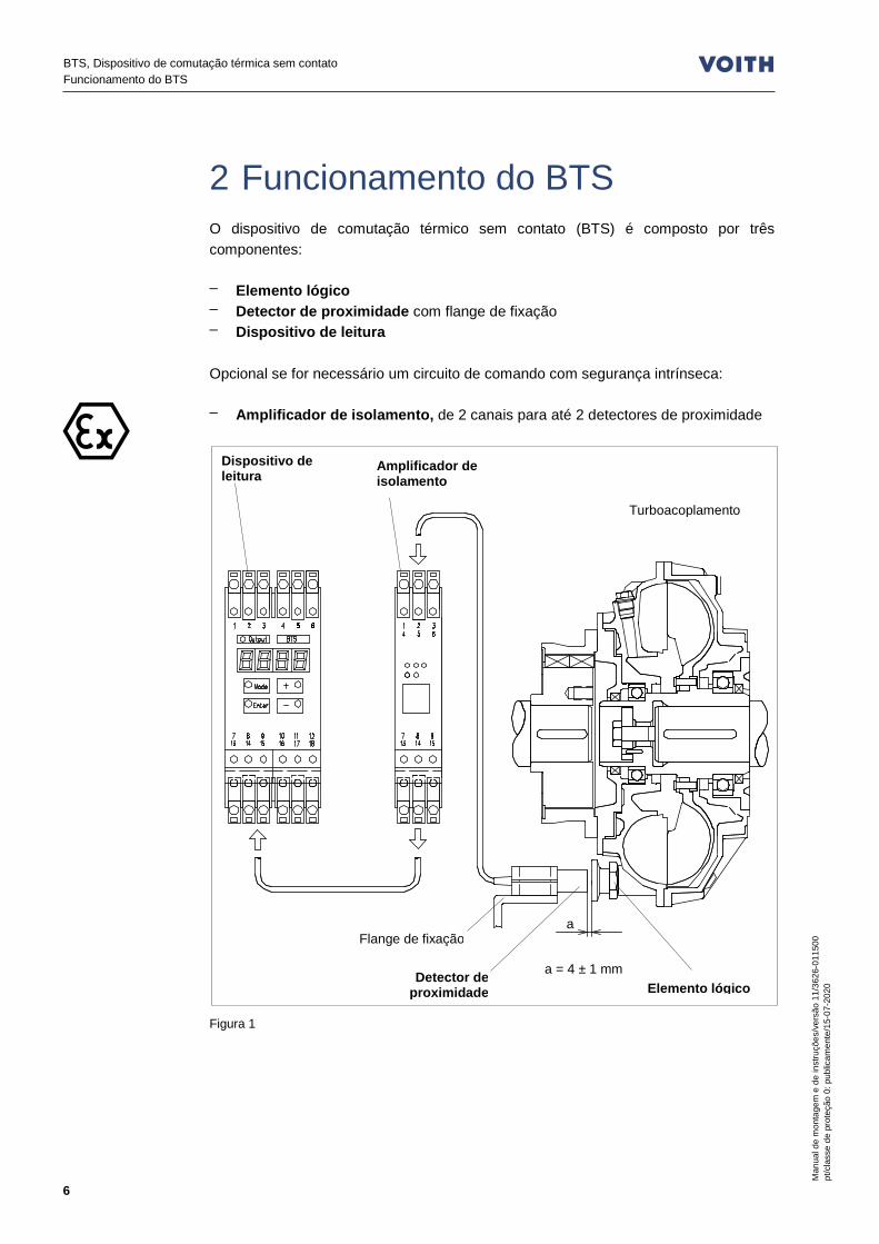
2 Funcionamento do BTS O dispositivo de comutação térmico sem contato (BTS) é composto por três componentes: – Elemento lógico – Detector de proximidade com flange de fixação – Dispositivo de leitura
Opcional se for necessário um circuito de comando com segurança intrínseca: – Amplificador de isolamento, de 2 canais para até 2 detectores de proximidade
Figura 1
a = 4 ± 1 mm
a
Amplificador de isolamento
Turboacoplamento
Detector de proximidade
Flange de fixação
Dispositivo de leitura
Elemento lógico
Man
ual d
e m
onta
gem
e d
e in
stru
ções
/ver
são
11/3
626-
0115
00
pt/c
lass
e de
pro
teçã
o 0:
pub
licam
ente
/15-
07-2
020
7
BTS, Dispositivo de comutação térmica sem contato Funcionamento do BTS
2.1 Elemento lógico O elemento lógico é um componente passivo (equipamento elétrico simples. É aparafusado à roda exterior ou ao revestimento do turboacoplamento. Dessa forma, é estabelecido um contato térmico entre o elemento lógico e o turboacoplamento através do fluido de serviço. O elemento lógico tem integrado uma bobina e um interruptor térmico. O ponto de ativação do interruptor térmico corresponde à temperatura de ativação do elemento lógico. Se a temperatura nominal de ativação for inferior, o interruptor térmico é fechado e a bobina curto-circuitada. Se a temperatura nominal de ativação for superior, o interruptor térmico é aberto e o circuito interrompido. Em caso de descida da temperatura, o interruptor térmico fecha novamente o circuito. O BTS fica novamente operacional. 2.2 Detector de proximidade O detector de proximidade foi concebido como sensor polarizado de dois fios. Ele funciona segundo o princípio do sensor indutivo. O detector de proximidade inclui um oscilador eletrônico que gera uma oscilação de alta frequência. Enquanto elemento condicionador da frequência, o oscilador inclui um circuito ressonante, composto por uma bobina e um condensador. A bobina de circuito ressonante está montada na cabeça do sensor. Através dessa bobina, é gerado um campo eletromagnético alternado na cabeça do sensor. 2.3 Dispositivo de leitura O dispositivo de leitura é uma unidade eletrônica que registra pulsos elétricos e avalia o intervalo entre os pulsos. A leitura é iniciada ou ao ligar a tensão de alimentação ou através de um sinal de ativação externo. Após o início da leitura, a leitura dos pulsos tem que ser desativada por um período de tempo regulável (tempo de inibição de partida). Um relé com contato inversor se desliga caso o número de pulsos por unidade de tempo não chegue a atingir um determinado valor mínimo. 2.4 Amplificador de isolamento O amplificador de isolamento transmite sinais digitais da área potencialmente explosiva. Os emissores de sinal podem ser sensores ou contatos mecânicos. As entradas com segurança intrínseca estão bem isoladas da saída e da rede.
Temperatura nominal de ativação Capítulo 3.1
BTS, Dispositivo de comutação térmica sem contato Funcionamento do BTS
Man
ual d
e m
onta
gem
e d
e in
stru
ções
/ver
são
11/3
626-
0115
00
pt/c
lass
e de
pro
teçã
o 0:
pub
licam
ente
/15-
07-2
020
8
2.5 Interação dos componentes do BTS Em vez de um parafuso cego, o elemento lógico é aparafusado ao turboacoplamento. O detector de proximidade é montado em paralelismo axial com o turboacoplamento com o flange de fixação, sendo ligado ao dispositivo de leitura. A bobina do elemento lógico é acoplada por indução à bobina do detector de proximidade, caso o elemento lógico se encontre depois da cabeça do detector de proximidade. Com o interruptor térmico fechado, a energia é transmitida do detector de proximidade para o elemento lógico. O oscilador é atenuado, consumindo menos corrente. Se a temperatura do acoplamento exceder a temperatura de ativação do elemento lógico, o interruptor térmico interrompe o circuito elétrico no elemento lógico. O elemento lógico deixa de poder atenuar o oscilador no detector de proximidade. O dispositivo de leitura detecta a atenuação do detector de proximidade devido ao respectivo consumo de corrente. Caso o turboacoplamento no qual está aparafusado o elemento lógico rode, o elemento lógico inicia um movimento contínuo passando pelo detector de proximidade. Dessa forma, são gerados pulsos de supressão contínuos. O relé de saída do dispositivo de leitura está ativo. No caso de temperatura excessiva, esses pulsos de atenuação são excluídos, ou seja, a frequência limite ajustada no dispositivo de leitura não é alcançada. O dispositivo de leitura detecta a ausência dos pulsos e o relé de saída se desliga. Na partida do turboacoplamento, é definido um tempo de inibição de partida no dispositivo de leitura. Enquanto a inibição de partida estiver ativa, o relé de saída permanece ativo. Decorrido o período definido, a velocidade do turboacoplamento com o elemento lógico deverá ter excedido a frequência limite definida.
ATENÇÃO
Perigo de danos pessoais e materiais Após a desconexão, o controle tem que ser bloqueado de forma a impedir qualquer nova partida automática. • Desligue o equipamento no qual o turboacoplamento está montado e
proteja-o contra nova ligação. • Sempre que forem efetuados trabalhos no turboacoplamento e no BTS,
certifique-se de que tanto o motor de acionamento como a máquina de serviço estão parados e de que a partida está excluída, em quaisquer circunstâncias.
• A nova partida só deverá ser efetuada se a temperatura do turboacoplamento for inferior à temperatura máxima permitida para a conexão do motor.
Montagem, posição Capítulo 2
Frequência limite Capítulo 3.3.1
Temperatura máxima permitida Manual de instruções do turboacoplamento
Man
ual d
e m
onta
gem
e d
e in
stru
ções
/ver
são
11/3
626-
0115
00
pt/c
lass
e de
pro
teçã
o 0:
pub
licam
ente
/15-
07-2
020
9
BTS, Dispositivo de comutação térmica sem contato Dados técnicos
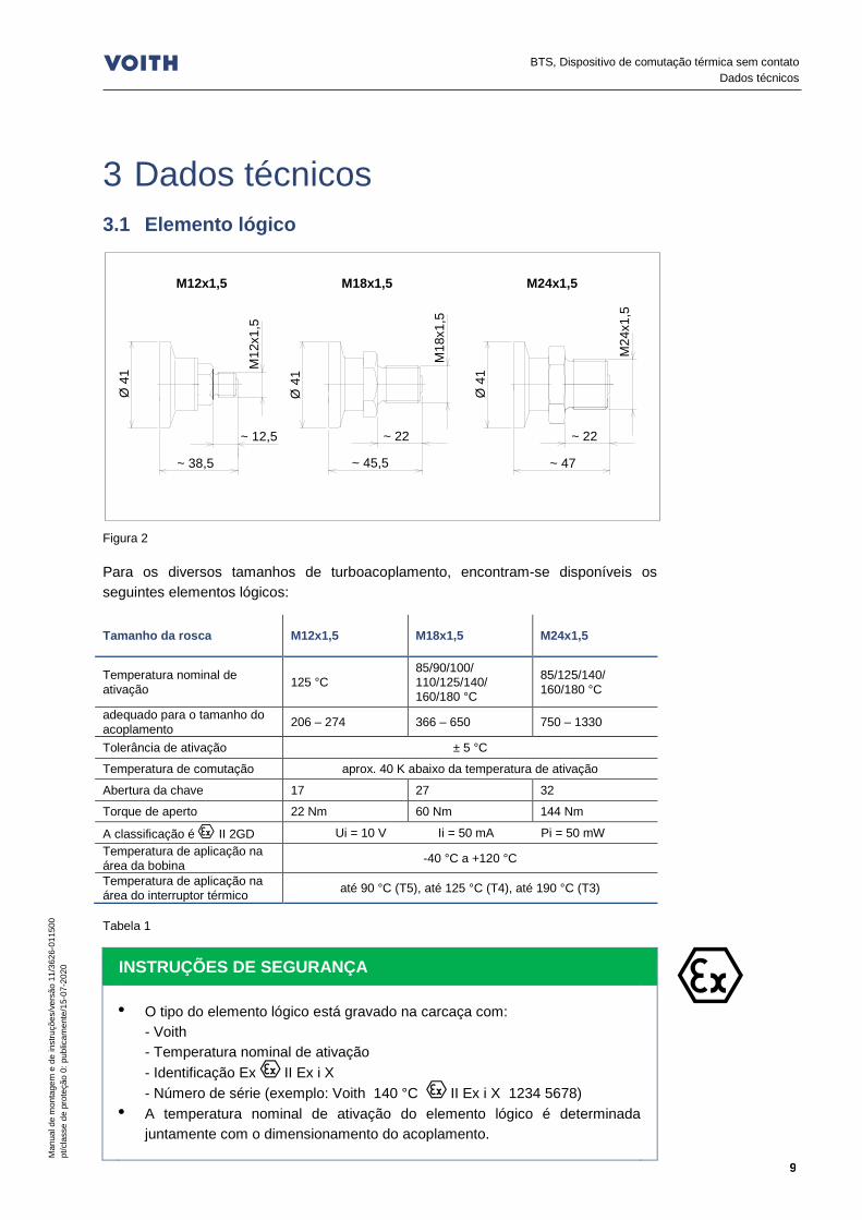
3 Dados técnicos 3.1 Elemento lógico
Figura 2 Para os diversos tamanhos de turboacoplamento, encontram-se disponíveis os seguintes elementos lógicos:
Tamanho da rosca M12x1,5 M18x1,5 M24x1,5
Temperatura nominal de ativação 125 °C
85/90/100/ 110/125/140/ 160/180 °C
85/125/140/ 160/180 °C
adequado para o tamanho do acoplamento 206 – 274 366 – 650 750 – 1330
Tolerância de ativação ± 5 °C
Temperatura de comutação aprox. 40 K abaixo da temperatura de ativação
Abertura da chave 17 27 32
Torque de aperto 22 Nm 60 Nm 144 Nm
A classificação é II 2GD Ui = 10 V Ii = 50 mA Pi = 50 mW Temperatura de aplicação na área da bobina -40 °C a +120 °C
Temperatura de aplicação na área do interruptor térmico até 90 °C (T5), até 125 °C (T4), até 190 °C (T3)
Tabela 1
INSTRUÇÕES DE SEGURANÇA
• O tipo do elemento lógico está gravado na carcaça com: - Voith - Temperatura nominal de ativação - Identificação Ex II Ex i X - Número de série (exemplo: Voith 140 °C II Ex i X 1234 5678)
• A temperatura nominal de ativação do elemento lógico é determinada juntamente com o dimensionamento do acoplamento.
~ 47
~ 22
~ 45,5
~ 22
~ 38,5
~ 12,5
M24x1,5 M12x1,5 M18x1,5
Ø 4
1
Ø 4
1 M12
x1,5
M18
x1,5
M24
x1,5
Ø 4
1
BTS, Dispositivo de comutação térmica sem contato Dados técnicos
Man
ual d
e m
onta
gem
e d
e in
stru
ções
/ver
são
11/3
626-
0115
00
pt/c
lass
e de
pro
teçã
o 0:
pub
licam
ente
/15-
07-2
020
10
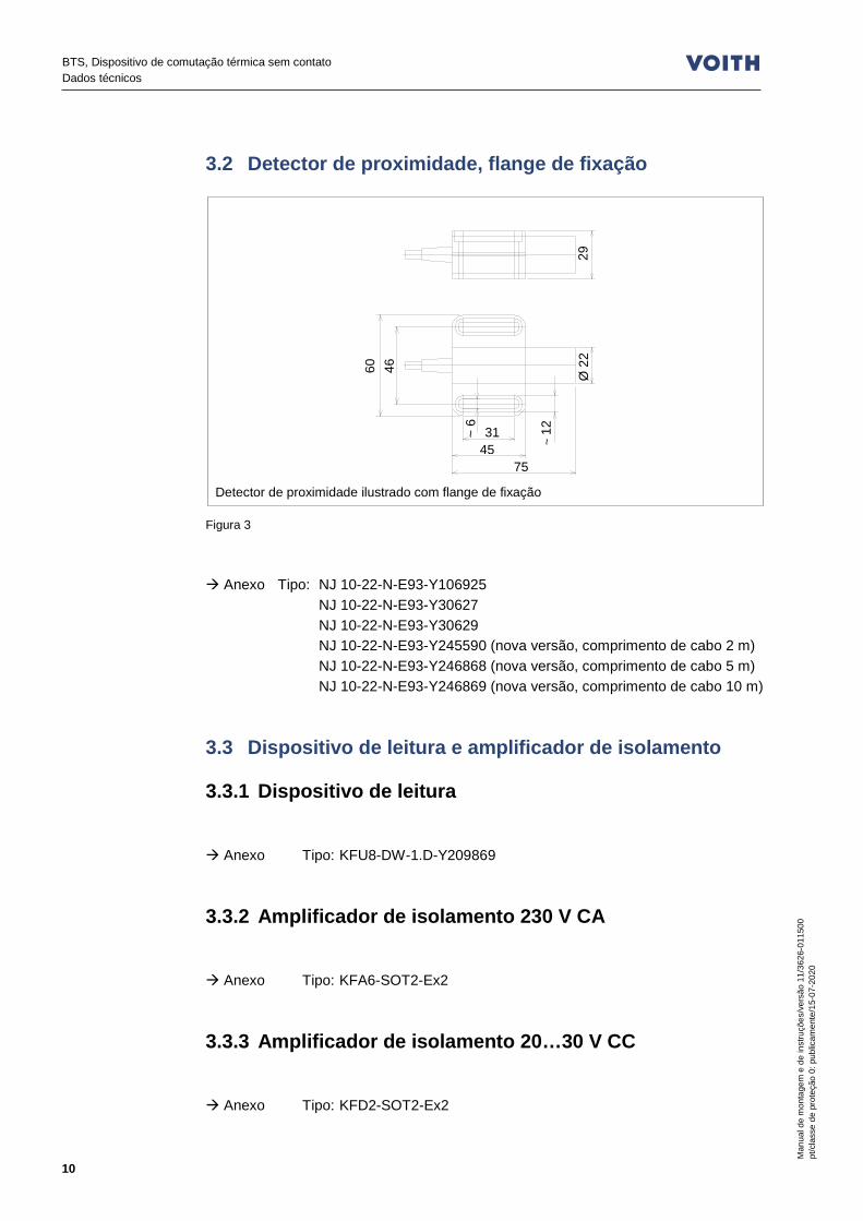
3.2 Detector de proximidade, flange de fixação
Figura 3 Anexo Tipo: NJ 10-22-N-E93-Y106925 NJ 10-22-N-E93-Y30627 NJ 10-22-N-E93-Y30629 NJ 10-22-N-E93-Y245590 (nova versão, comprimento de cabo 2 m) NJ 10-22-N-E93-Y246868 (nova versão, comprimento de cabo 5 m) NJ 10-22-N-E93-Y246869 (nova versão, comprimento de cabo 10 m) 3.3 Dispositivo de leitura e amplificador de isolamento 3.3.1 Dispositivo de leitura Anexo Tipo: KFU8-DW-1.D-Y209869 3.3.2 Amplificador de isolamento 230 V CA Anexo Tipo: KFA6-SOT2-Ex2 3.3.3 Amplificador de isolamento 20…30 V CC Anexo Tipo: KFD2-SOT2-Ex2
31
Ø 2
2 29
~ 12
~ 6
46
60
Detector de proximidade ilustrado com flange de fixação
45 75
Man
ual d
e m
onta
gem
e d
e in
stru
ções
/ver
são
11/3
626-
0115
00
pt/c
lass
e de
pro
teçã
o 0:
pub
licam
ente
/15-
07-2
020
11
BTS, Dispositivo de comutação térmica sem contato Instruções de utilização
4 Instruções de utilização Este manual irá ajudá-lo a usar o dispositivo de comutação térmico sem contato (BTS) de forma segura, apropriada e econômica. O cumprimento das instruções incluídas nesse manual permite-lhe: – aumentar a confiabilidade e a vida útil do equipamento; – evitar perigos; – diminuir o número de reparos e tempos de inatividade. Esse manual deve: – estar sempre disponível no local de utilização da máquina, – ser lido e usado por todas as pessoas que executam trabalhos no equipamento
ou o colocam em operação. Encontrará mais documentos anexados a esse manual de instruções, os quais têm que ser obrigatoriamente respeitados. O dispositivo de comutação térmico sem contato foi projetado de acordo com os mais recentes avanços tecnológicos e as regras técnicas de segurança reconhecidas. Contudo, um manuseio incorreto e o uso não previsto podem colocar em risco a vida e integridade física do usuário ou de terceiros e/ou provocar danos no equipamento e em outros objetos. Peças de reposição: As peças de reposição têm que estar em conformidade com os requisitos técnicos estabelecidos pela Voith. Isso será garantido sempre que sejam usadas peças de reposição originais. A montagem e/ou o uso de peças de reposição que não sejam originais podem alterar negativamente as características estruturais do BTS e comprometer a segurança. A Voith não se responsabiliza por quaisquer danos resultantes do uso de peças de reposição que não sejam originais. Para a manutenção, use um equipamento de oficina adequado. A manutenção e/ou reparo especializados somente podem ser garantidos pelo fabricante ou por uma oficina autorizada.
BTS, Dispositivo de comutação térmica sem contato Instruções de utilização
Man
ual d
e m
onta
gem
e d
e in
stru
ções
/ver
são
11/3
626-
0115
00
pt/c
lass
e de
pro
teçã
o 0:
pub
licam
ente
/15-
07-2
020
12
Esse manual foi elaborado com o máximo cuidado possível. Para informações mais detalhadas, entre em contato com: Voith Group St. Pöltener Str. 43 89522 Heidenheim, ALEMANHA Telefone: + 49 7951 32 1666 E-mail: [email protected] Internet: www.voith.com/fluid-couplings © Voith 2020. A transmissão e reprodução desse documento e o uso e a divulgação do seu conteúdo são proibidos, desde que não esteja expressamente autorizado. Infrações sujeitas a indenização por perdas e danos. Reservados todos os direitos de registro de patentes, desenhos industriais ou modelos industriais. A empresa Voith reserva-se o direito de efetuar alterações.
Man
ual d
e m
onta
gem
e d
e in
stru
ções
/ver
são
11/3
626-
0115
00
pt/c
lass
e de
pro
teçã
o 0:
pub
licam
ente
/15-
07-2
020
13
BTS, Dispositivo de comutação térmica sem contato Segurança
5 Segurança 5.1 Instruções de segurança No manual de instruções são usadas instruções de segurança com as seguintes denominações e símbolos descritos. 5.1.1 Estrutura das instruções de segurança
DESIGNAÇÃO DE PERIGOS
Consequências dos perigos Origem dos perigos • Medidas de segurança
Designação de perigos A designação de perigos divide o grau de perigosidade em vários níveis:
Designação de perigos Grau de perigosidade
PERIGO Morte ou ferimentos graves (danos pessoais irreversíveis)
ATENÇÃO Possibilidade de morte ou de ferimentos muito graves
CUIDADO Possibilidade de ferimentos leves ou menores
NOTA Possibilidade de danos materiais - do produto - da área circundante
INSTRUÇÕES DE SEGURANÇA
Instruções gerais de utilização, informações úteis, procedimentos de trabalho seguros e medidas de segurança adequadas
Tabela 2 Consequências dos perigos A consequência do perigo indica o tipo de perigo. Origem dos perigos A origem dos perigos indica a respectiva causa. Medidas de segurança As medidas de segurança descrevem as medidas a adotar face aos perigos.
BTS, Dispositivo de comutação térmica sem contato Segurança
Man
ual d
e m
onta
gem
e d
e in
stru
ções
/ver
são
11/3
626-
0115
00
pt/c
lass
e de
pro
teçã
o 0:
pub
licam
ente
/15-
07-2
020
14
5.1.2 Definição dos sinais de segurança Símbolo Definição
Perigo de explosão A identificação através do símbolo de perigo de explosão chama a atenção para eventuais perigos a serem tidos em conta em caso de utilização em atmosferas potencialmente explosivas.
Tabela 3
5.2 Uso devido – O dispositivo de comutação térmico sem contato (BTS) destina-se a monitorar à
distância a temperatura dos turboacoplamentos Voith e foi projetado para aplicação industrial. Qualquer outra utilização fora deste âmbito, como por exemplo, em condições operacionais ou de utilização não previstas, será considerada indevida.
– A utilização devida inclui também a observação do presente manual de montagem e de instruções.
– O fabricante não se responsabiliza por danos resultantes do uso indevido. Esse risco é da total responsabilidade do usuário.
5.3 Uso indevido – Não ser respeitado o dimensionamento. – Qualquer outra utilização fora deste âmbito, como por exemplo, para obter
potências e velocidades mais elevadas, ou para condições operacionais não previstas, será considerada indevida.
– Além disso, não devem ser usados dispositivos BTS ou peças de reposição de terceiros.
5.4 Indicações gerais de perigo Em todos os trabalhos no dispositivo de comutação térmico sem contato devem ser cumpridas as normas locais em matéria de prevenção de acidentes, bem como as normas para a instalação de equipamentos elétricos!
ATENÇÃO
Perigo de explosão Em caso de incumprimento das normas ou modificação indevida, existe o perigo de explosão. • Em atmosferas potencialmente explosivas, os trabalhos no dispositivo de
comutação térmico sem contato devem ser efetuados respeitando as normas locais em matéria de prevenção de acidentes e as normas para a montagem de equipamentos elétricos! Não são permitidas modificações em equipamentos elétricos para áreas potencialmente explosivas, incluindo cabos de conexão.
Dimensionamento Manual de instruções Turboacoplamento
Man
ual d
e m
onta
gem
e d
e in
stru
ções
/ver
são
11/3
626-
0115
00
pt/c
lass
e de
pro
teçã
o 0:
pub
licam
ente
/15-
07-2
020
15
BTS, Dispositivo de comutação térmica sem contato Segurança
Perigos durante os trabalhos no dispositivo de comutação térmico sem contato:
PERIGO
Choque elétrico Caso sejam montados ou fixados incorretamente componentes elétricos e as ligações elétricas estejam desconectadas, podem ocorrer choques elétricos ou ferimentos graves em pessoas, resultando eventualmente em morte. Componentes elétricos montados ou fixados incorretamente e ligações elétricas desconectadas podem provocar danos no equipamento. • A conexão à rede de alimentação elétrica deve ser feita por um eletricista
qualificado, respeitando a tensão nominal e o consumo máximo de corrente. • A tensão da rede tem que coincidir com a tensão de rede indicada na placa
de características elétricas. • A rede tem de estar protegida por um fusível elétrico.
Choque elétrico:
PERIGO
Processos eletrostáticos Uma pessoa pode sofrer um choque elétrico devido a uma descarga estática. • A instalação do equipamento, no qual o turboacoplamento está montado,
tem que ser realizada por um eletricista. • A máquina e a instalação elétrica dispõem de conexões de aterramento.
BTS, Dispositivo de comutação térmica sem contato Segurança
Man
ual d
e m
onta
gem
e d
e in
stru
ções
/ver
são
11/3
626-
0115
00
pt/c
lass
e de
pro
teçã
o 0:
pub
licam
ente
/15-
07-2
020
16
Trabalhos no turboacoplamento:
ATENÇÃO
Perigo de ferimentos Durante a realização de trabalhos no turboacoplamento existe o perigo de ocorrência de ferimentos por corte, esmagamento, queimaduras devido a superfícies quentes e queimaduras por frio, em caso de temperaturas negativas. • Respeite o manual de montagem e de instruções do turboacoplamento! • Nunca toque no turboacoplamento sem luvas de proteção. • Inicie os trabalhos apenas quando o turboacoplamento estiver frio. • Durante os trabalhos no turboacoplamento, certifique-se de que dispõe de
iluminação suficiente, de um espaço de trabalho suficientemente grande e de boa ventilação.
• Desligue o equipamento no qual o turboacoplamento está montado e proteja-o contra nova ligação.
• Sempre que forem efetuados trabalhos no turboacoplamento, certifique-se de que tanto o motor de acionamento como a máquina de serviço estão parados e de que a partida está excluída em quaisquer circunstâncias.
Ruído:
ATENÇÃO
Perda de audição, lesões auditivas permanentes O turboacoplamento gera ruído durante a operação. Se o nível de pressão sonora LPA, 1m equivalente com ponderação A for superior a 80 dB (A), podem ocorrer lesões auditivas. • Use proteção auditiva.
Nível de pressão sonora Folha de rosto do manual de instruções do turboacoplamento
Man
ual d
e m
onta
gem
e d
e in
stru
ções
/ver
são
11/3
626-
0115
00
pt/c
lass
e de
pro
teçã
o 0:
pub
licam
ente
/15-
07-2
020
17
BTS, Dispositivo de comutação térmica sem contato Segurança
Salpicos e vazamento de fluido de serviço:
ATENÇÃO
Risco de cegueira devido a salpicos do fluido de serviço quente, perigo de queimaduras Em caso de sobrecarga térmica do turboacoplamento, os parafusos fusíveis são ativados. O vazamento do fluido de serviço ocorre através desses parafusos fusíveis. Isso só acontece em caso de uso indevido. • As pessoas que mantenham nas proximidades do turboacoplamento têm
que usar óculos de proteção. • Certifique-se de que os salpicos do fluido de serviço não entram em contato
com pessoas. • Após a projeção dos parafusos fusíveis, desligue imediatamente o
acionamento. • Os dispositivos elétricos que se encontram junto do turboacoplamento têm
que estar protegidos contra projeção.
ATENÇÃO
Perigo de incêndio Após a ativação dos parafusos fusíveis, os salpicos de óleo podem inflamar-se em superfícies quentes e provocar um incêndio, bem como liberar gases e vapores tóxicos. • Certifique-se de que os salpicos do fluido de serviço não entram em contato
com as peças quentes da máquina, dispositivos de aquecimento, faíscas ou chamas abertas.
• Após a ativação dos parafusos fusíveis, desligar imediatamente a máquina acionadora.
• Respeite as indicações que constam nas folhas de dados de segurança.
CUIDADO
Perigo de escorregamento Perigo de escorregamento devido a salpicos de solda liberados pelos parafusos fusíveis e a salpicos de fluido de serviço. • Providencie uma bandeja de coleta com as dimensões adequadas. • Remover imediatamente os salpicos de solda liberados pelo parafuso fusível
e os salpicos do fluido de serviço. • Respeite as indicações que constam nas folhas de dados de segurança.
Uso indevido Capítulo 5.3
BTS, Dispositivo de comutação térmica sem contato Segurança
Man
ual d
e m
onta
gem
e d
e in
stru
ções
/ver
são
11/3
626-
0115
00
pt/c
lass
e de
pro
teçã
o 0:
pub
licam
ente
/15-
07-2
020
18
5.5 Perigos residuais
ATENÇÃO
Perigo de danos pessoais e materiais As consequências pelo uso indevido ou pela operação incorreta podem ser a morte, ferimentos graves ou leves, bem como danos materiais e ambientais. • Somente pessoas com formação e instrução suficientes e autorizadas
podem trabalhar no ou com o turboacoplamento ou com o dispositivo de comutação térmico sem contato.
• Respeitar os avisos e as instruções de segurança.
5.6 Atuação em caso de acidente
INSTRUÇÕES DE SEGURANÇA
• Em caso de acidente, têm que ser cumpridas as normas locais, bem como as instruções de operação e as medidas de segurança para o operador.
5.7 Informações relativas à operação
INSTRUÇÕES DE SEGURANÇA
• Se forem detectadas irregularidades durante a operação, a unidade de acionamento tem que ser de imediato desligada.
Dispositivos de monitoramento:
NOTA
Danos materiais Danos no turboacoplamento devido à inoperabilidade de dispositivos de monitoramento. • Verifique se os dispositivos de monitoramento existentes estão operacionais. • Repare de imediato os dispositivos de monitoramento defeituosos. • Nunca ligar os dispositivos de segurança em ponte.
Man
ual d
e m
onta
gem
e d
e in
stru
ções
/ver
são
11/3
626-
0115
00
pt/c
lass
e de
pro
teçã
o 0:
pub
licam
ente
/15-
07-2
020
19
BTS, Dispositivo de comutação térmica sem contato Segurança
5.8 Qualificação do pessoal Todos os trabalhos, como por exemplo, de transporte, armazenamento, instalação, conexão elétrica, colocação em operação, operação, manutenção, conservação e reparo somente podem ser executados por pessoal técnico qualificado e autorizado. Pessoal técnico qualificado no sentido previsto nesse manual de instruções são as pessoas que estão familiarizadas com o transporte, armazenamento, instalação, conexão elétrica, colocação em operação, manutenção, conservação e reparo e que possuem as qualificações adequadas para o desempenho das suas atividades. A qualificação tem de ser garantida através de treinamento e instrução. Esse pessoal deve ter treinamento, instrução ou autorização para: – operar ou fazer manutenção dos equipamentos, de forma apropriada e conforme
os padrões da técnica de segurança; – usar devidamente os dispositivos de elevação, meios e pontos de fixação; – descartar adequadamente os meios e seus componentes, como por exemplo,
graxas lubrificantes; – preservar e utilizar o equipamento de segurança conforme os padrões da técnica
de segurança; – evitar acidentes e prestar os primeiros socorros. O pessoal em formação somente pode executar trabalhos no turboacoplamento ou no dispositivo de comutação térmico sem contato sob a supervisão de uma pessoa qualificada e autorizada. O pessoal selecionado para os trabalhos no dispositivo de comutação térmico sem contato deve: – ser responsável; – ter, pelo menos, a idade mínima prevista na legislação; – possuir formação, instrução e autorização para os trabalhos previstos; – cumprir as normas EN 1127-1 Anexo A e EN 1127-1 parágrafo 7 durante os
trabalhos em atmosferas potencialmente explosivas. Utilizar somente ferramentas autorizadas para uso em áreas potencialmente explosivas. Evitar a formação de faíscas.
5.9 Inspeção dos produtos Nos termos da lei, somos obrigados a inspecionar os nossos produtos mesmo após a respectiva entrega. Portanto, comunique todo e qualquer assunto que seja do nosso interesse. Por exemplo: – Alteração de dados operacionais. – Experiências com o equipamento. – Falhas recorrentes. – Dificuldades relativas a esse manual de montagem e de instruções.
Nosso endereço Página 2
BTS, Dispositivo de comutação térmica sem contato Instalação
Man
ual d
e m
onta
gem
e d
e in
stru
ções
/ver
são
11/3
626-
0115
00
pt/c
lass
e de
pro
teçã
o 0:
pub
licam
ente
/15-
07-2
020
20
6 Instalação ATENÇÃO
Perigo de ferimentos Durante os trabalhos no dispositivo de comutação térmico sem contato, observar especialmente o capítulo 5 (Segurança)! • Antes de iniciar a instalação, certifique-se de que não está garantida a
ausência de tensão em todos os componentes. • Os parafusos fusíveis protegem o turboacoplamento de danos resultantes de
uma sobrecarga térmica. Mesmo ao usar o BTS, os parafusos fusíveis de segurança existentes não podem ser trocados por parafusos cegos ou parafusos fusíveis com temperaturas nominais de ativação diferentes!
• Nunca operar o turboacoplamento sem parafusos fusíveis!
6.1 Estado de entrega – O elemento lógico com anel de vedação, – o detector de proximidade com flange de fixação e – o dispositivo de leitura geralmente são fornecidos soltos, em conjunto com o turboacoplamento.
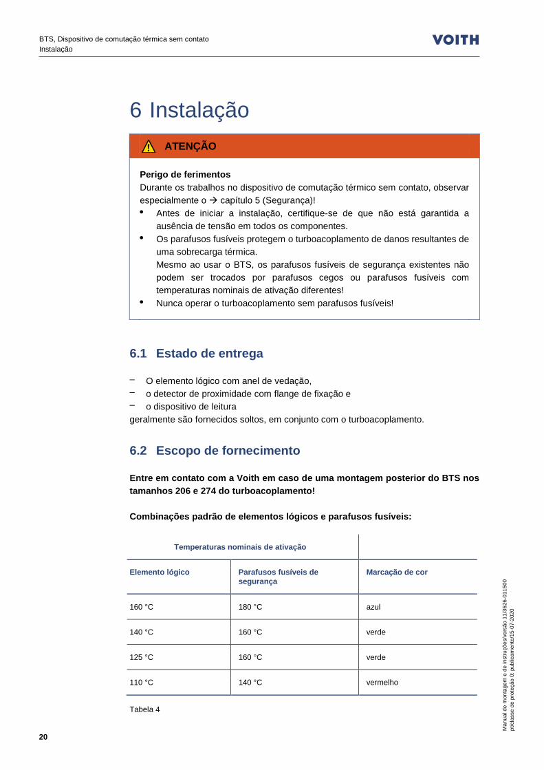
6.2 Escopo de fornecimento Entre em contato com a Voith em caso de uma montagem posterior do BTS nos tamanhos 206 e 274 do turboacoplamento! Combinações padrão de elementos lógicos e parafusos fusíveis:
Temperaturas nominais de ativação
Elemento lógico Parafusos fusíveis de segurança
Marcação de cor
160 °C 180 °C azul
140 °C 160 °C verde
125 °C 160 °C verde
110 °C 140 °C vermelho
Tabela 4
Man
ual d
e m
onta
gem
e d
e in
stru
ções
/ver
são
11/3
626-
0115
00
pt/c
lass
e de
pro
teçã
o 0:
pub
licam
ente
/15-
07-2
020
21
BTS, Dispositivo de comutação térmica sem contato Instalação
A correspondência entre elementos lógicos e parafusos fusíveis pode variar de acordo com as características do projeto. Temperaturas nominais de ativação do elemento lógico divergentes (85 °C, 90 °C, 100 °C, 110 °C, 125 °C, 140 °C, 160 °C e 180 °C) também estão disponíveis ( capítulo 13).
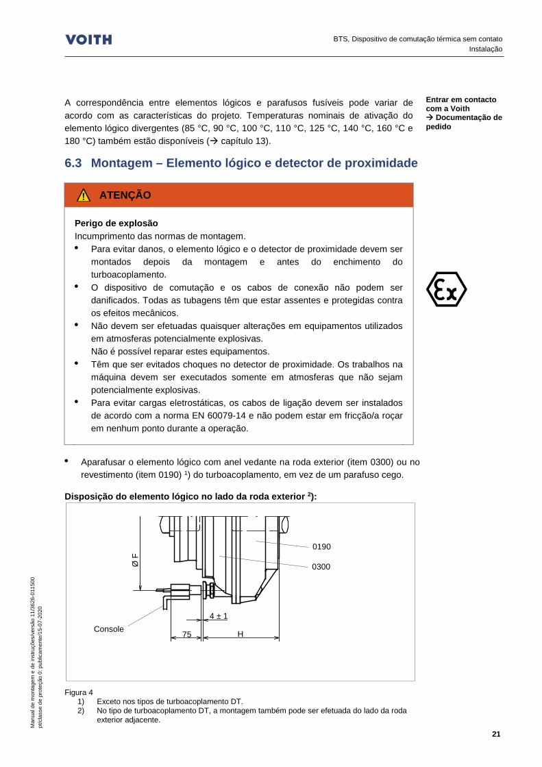
6.3 Montagem – Elemento lógico e detector de proximidade
ATENÇÃO
Perigo de explosão Incumprimento das normas de montagem. • Para evitar danos, o elemento lógico e o detector de proximidade devem ser
montados depois da montagem e antes do enchimento do turboacoplamento.
• O dispositivo de comutação e os cabos de conexão não podem ser danificados. Todas as tubagens têm que estar assentes e protegidas contra os efeitos mecânicos.
• Não devem ser efetuadas quaisquer alterações em equipamentos utilizados em atmosferas potencialmente explosivas. Não é possível reparar estes equipamentos.
• Têm que ser evitados choques no detector de proximidade. Os trabalhos na máquina devem ser executados somente em atmosferas que não sejam potencialmente explosivas.
• Para evitar cargas eletrostáticas, os cabos de ligação devem ser instalados de acordo com a norma EN 60079-14 e não podem estar em fricção/a roçar em nenhum ponto durante a operação.
• Aparafusar o elemento lógico com anel vedante na roda exterior (item 0300) ou no
revestimento (item 0190) 1) do turboacoplamento, em vez de um parafuso cego. Disposição do elemento lógico no lado da roda exterior 2):
Figura 4
1) Exceto nos tipos de turboacoplamento DT. 2) No tipo de turboacoplamento DT, a montagem também pode ser efetuada do lado da roda
exterior adjacente.
Entrar em contacto com a Voith Documentação de pedido
75
Ø F
H
0190
0300
Console
4 ± 1
BTS, Dispositivo de comutação térmica sem contato Instalação
Man
ual d
e m
onta
gem
e d
e in
stru
ções
/ver
são
11/3
626-
0115
00
pt/c
lass
e de
pro
teçã
o 0:
pub
licam
ente
/15-
07-2
020
22
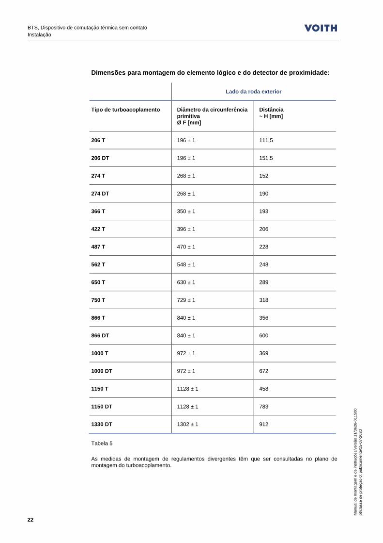
Dimensões para montagem do elemento lógico e do detector de proximidade:
Lado da roda exterior
Tipo de turboacoplamento Diâmetro da circunferência primitiva Ø F [mm]
Distância ~ H [mm]
206 T 196 ± 1 111,5
206 DT 196 ± 1 151,5
274 T 268 ± 1 152
274 DT 268 ± 1 190
366 T 350 ± 1 193
422 T 396 ± 1 206
487 T 470 ± 1 228
562 T 548 ± 1 248
650 T 630 ± 1 289
750 T 729 ± 1 318
866 T 840 ± 1 356
866 DT 840 ± 1 600
1000 T 972 ± 1 369
1000 DT 972 ± 1 672
1150 T 1128 ± 1 458
1150 DT 1128 ± 1 783
1330 DT 1302 ± 1 912
Tabela 5 As medidas de montagem de regulamentos divergentes têm que ser consultadas no plano de montagem do turboacoplamento.
Man
ual d
e m
onta
gem
e d
e in
stru
ções
/ver
são
11/3
626-
0115
00
pt/c
lass
e de
pro
teçã
o 0:
pub
licam
ente
/15-
07-2
020
23
BTS, Dispositivo de comutação térmica sem contato Instalação
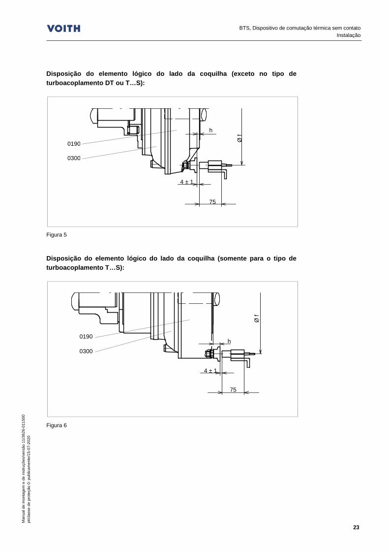
Disposição do elemento lógico do lado da coquilha (exceto no tipo de turboacoplamento DT ou T…S):
Figura 5 Disposição do elemento lógico do lado da coquilha (somente para o tipo de turboacoplamento T…S):
Figura 6
75
h
Ø f
0190
0300
4 ± 1
75
h
Ø f
0190
0300
4 ± 1
BTS, Dispositivo de comutação térmica sem contato Instalação
Man
ual d
e m
onta
gem
e d
e in
stru
ções
/ver
são
11/3
626-
0115
00
pt/c
lass
e de
pro
teçã
o 0:
pub
licam
ente
/15-
07-2
020
24
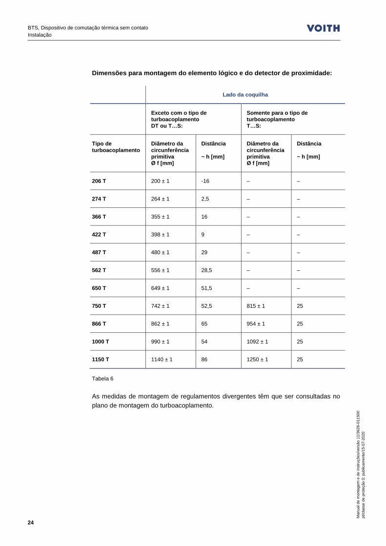
Dimensões para montagem do elemento lógico e do detector de proximidade:
Lado da coquilha
Exceto com o tipo de turboacoplamento DT ou T…S:
Somente para o tipo de turboacoplamento T…S:
Tipo de turboacoplamento
Diâmetro da circunferência primitiva Ø f [mm]
Distância ~ h [mm]
Diâmetro da circunferência primitiva Ø f [mm]
Distância ~ h [mm]
206 T 200 ± 1 -16 – –
274 T 264 ± 1 2,5 – –
366 T 355 ± 1 16 – –
422 T 398 ± 1 9 – –
487 T 480 ± 1 29 – –
562 T 556 ± 1 28,5 – –
650 T 649 ± 1 51,5 – –
750 T 742 ± 1 52,5 815 ± 1 25
866 T 862 ± 1 65 954 ± 1 25
1000 T 990 ± 1 54 1092 ± 1 25
1150 T 1140 ± 1 86 1250 ± 1 25
Tabela 6 As medidas de montagem de regulamentos divergentes têm que ser consultadas no plano de montagem do turboacoplamento.
Man
ual d
e m
onta
gem
e d
e in
stru
ções
/ver
são
11/3
626-
0115
00
pt/c
lass
e de
pro
teçã
o 0:
pub
licam
ente
/15-
07-2
020
25
BTS, Dispositivo de comutação térmica sem contato Instalação
NOTA
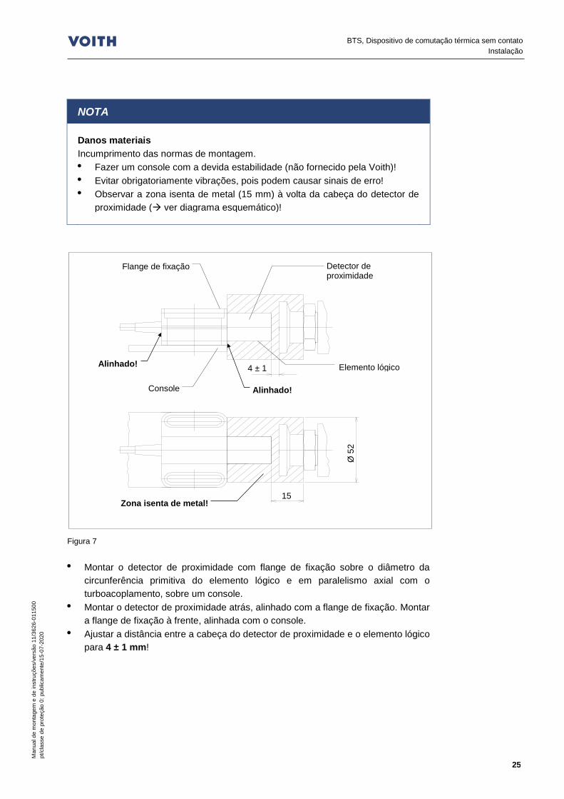
Danos materiais Incumprimento das normas de montagem. • Fazer um console com a devida estabilidade (não fornecido pela Voith)! • Evitar obrigatoriamente vibrações, pois podem causar sinais de erro! • Observar a zona isenta de metal (15 mm) à volta da cabeça do detector de
proximidade ( ver diagrama esquemático)!
Figura 7 • Montar o detector de proximidade com flange de fixação sobre o diâmetro da
circunferência primitiva do elemento lógico e em paralelismo axial com o turboacoplamento, sobre um console.
• Montar o detector de proximidade atrás, alinhado com a flange de fixação. Montar a flange de fixação à frente, alinhada com o console.
• Ajustar a distância entre a cabeça do detector de proximidade e o elemento lógico para 4 ± 1 mm!
15 Zona isenta de metal!
Console
Flange de fixação Detector de proximidade
Elemento lógico
Alinhado!
Alinhado! Ø
52
4 ± 1
BTS, Dispositivo de comutação térmica sem contato Instalação
Man
ual d
e m
onta
gem
e d
e in
stru
ções
/ver
são
11/3
626-
0115
00
pt/c
lass
e de
pro
teçã
o 0:
pub
licam
ente
/15-
07-2
020
26
6.4 Montagem, conexão – Dispositivo de leitura, amplificador de isolamento
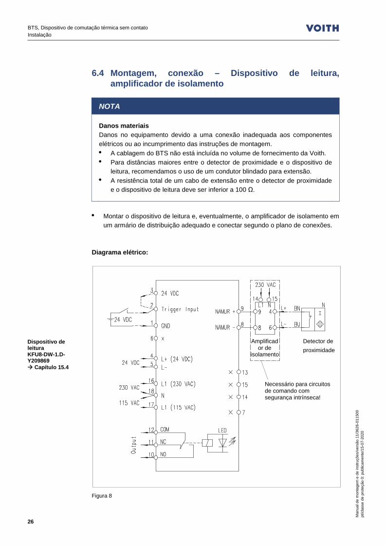
NOTA
Danos materiais Danos no equipamento devido a uma conexão inadequada aos componentes elétricos ou ao incumprimento das instruções de montagem. • A cablagem do BTS não está incluída no volume de fornecimento da Voith. • Para distâncias maiores entre o detector de proximidade e o dispositivo de
leitura, recomendamos o uso de um condutor blindado para extensão. • A resistência total de um cabo de extensão entre o detector de proximidade
e o dispositivo de leitura deve ser inferior a 100 Ω.
• Montar o dispositivo de leitura e, eventualmente, o amplificador de isolamento em
um armário de distribuição adequado e conectar segundo o plano de conexões. Diagrama elétrico:
Figura 8
Dispositivo de leitura KFU8-DW-1.D-Y209869 Capítulo 15.4
Detector de proximidade
Amplificador de
isolamento
Necessário para circuitos de comando com segurança intrínseca!
Man
ual d
e m
onta
gem
e d
e in
stru
ções
/ver
são
11/3
626-
0115
00
pt/c
lass
e de
pro
teçã
o 0:
pub
licam
ente
/15-
07-2
020
27
BTS, Dispositivo de comutação térmica sem contato Instalação
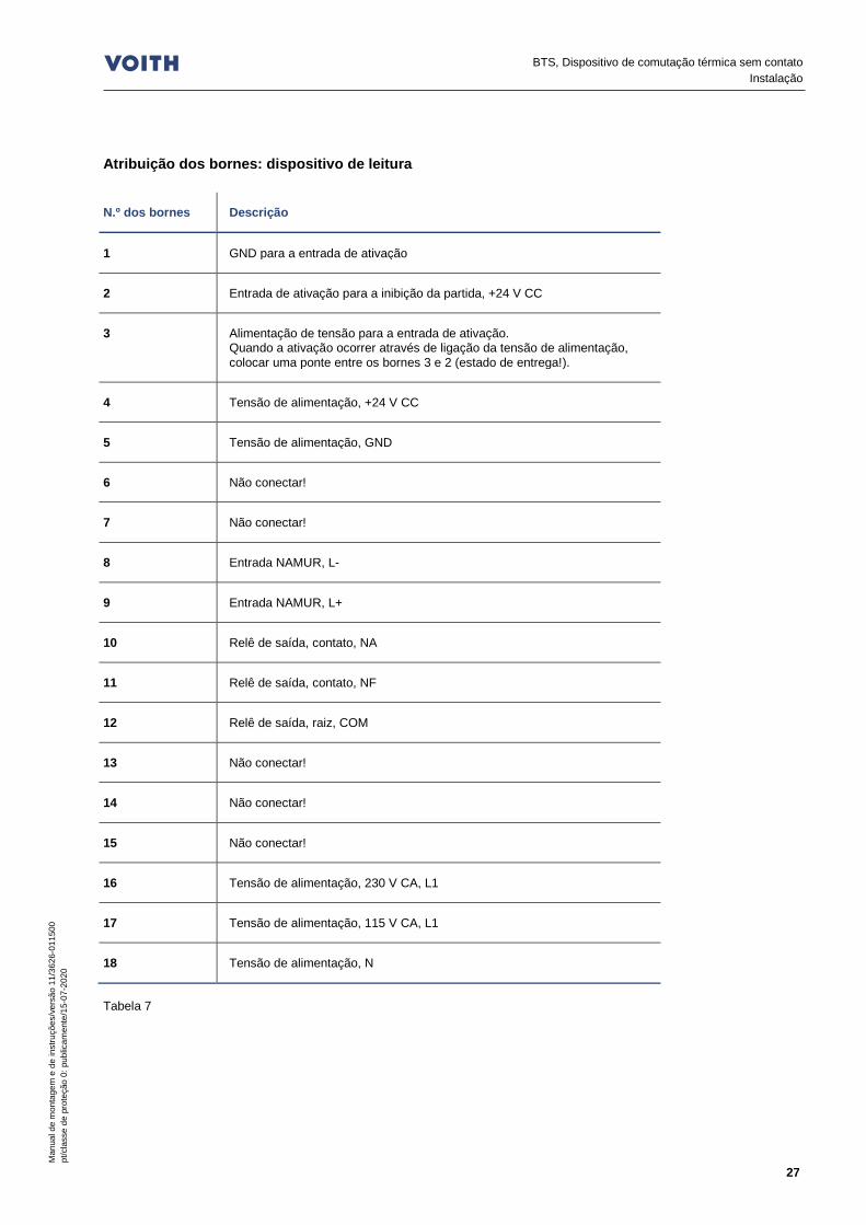
Atribuição dos bornes: dispositivo de leitura
N.º dos bornes Descrição
1 GND para a entrada de ativação
2 Entrada de ativação para a inibição da partida, +24 V CC
3 Alimentação de tensão para a entrada de ativação. Quando a ativação ocorrer através de ligação da tensão de alimentação, colocar uma ponte entre os bornes 3 e 2 (estado de entrega!).
4 Tensão de alimentação, +24 V CC
5 Tensão de alimentação, GND
6 Não conectar!
7 Não conectar!
8 Entrada NAMUR, L-
9 Entrada NAMUR, L+
10 Relê de saída, contato, NA
11 Relê de saída, contato, NF
12 Relê de saída, raiz, COM
13 Não conectar!
14 Não conectar!
15 Não conectar!
16 Tensão de alimentação, 230 V CA, L1
17 Tensão de alimentação, 115 V CA, L1
18 Tensão de alimentação, N
Tabela 7
BTS, Dispositivo de comutação térmica sem contato Instalação
Man
ual d
e m
onta
gem
e d
e in
stru
ções
/ver
são
11/3
626-
0115
00
pt/c
lass
e de
pro
teçã
o 0:
pub
licam
ente
/15-
07-2
020
28
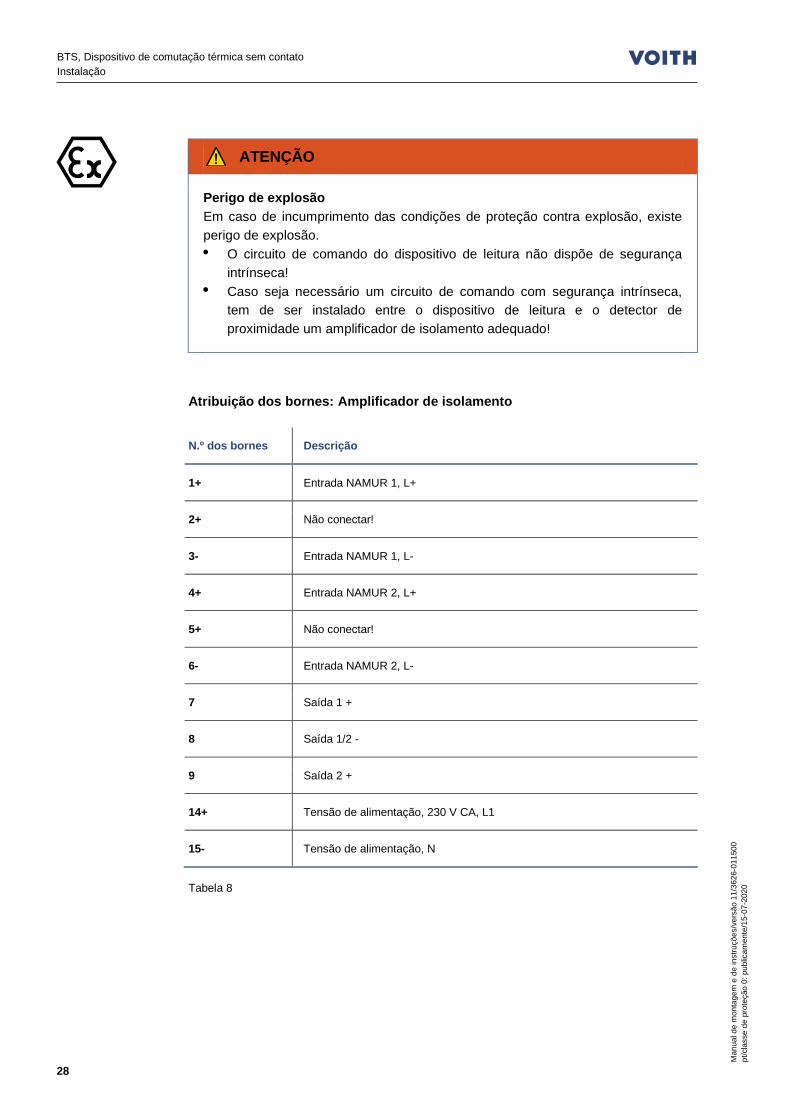
ATENÇÃO
Perigo de explosão Em caso de incumprimento das condições de proteção contra explosão, existe perigo de explosão. • O circuito de comando do dispositivo de leitura não dispõe de segurança
intrínseca! • Caso seja necessário um circuito de comando com segurança intrínseca,
tem de ser instalado entre o dispositivo de leitura e o detector de proximidade um amplificador de isolamento adequado!
Atribuição dos bornes: Amplificador de isolamento
N.º dos bornes Descrição
1+ Entrada NAMUR 1, L+
2+ Não conectar!
3- Entrada NAMUR 1, L-
4+ Entrada NAMUR 2, L+
5+ Não conectar!
6- Entrada NAMUR 2, L-
7 Saída 1 +
8 Saída 1/2 -
9 Saída 2 +
14+ Tensão de alimentação, 230 V CA, L1
15- Tensão de alimentação, N
Tabela 8
Man
ual d
e m
onta
gem
e d
e in
stru
ções
/ver
são
11/3
626-
0115
00
pt/c
lass
e de
pro
teçã
o 0:
pub
licam
ente
/15-
07-2
020
29
BTS, Dispositivo de comutação térmica sem contato Indicações e ajuste do dispositivo de leitura
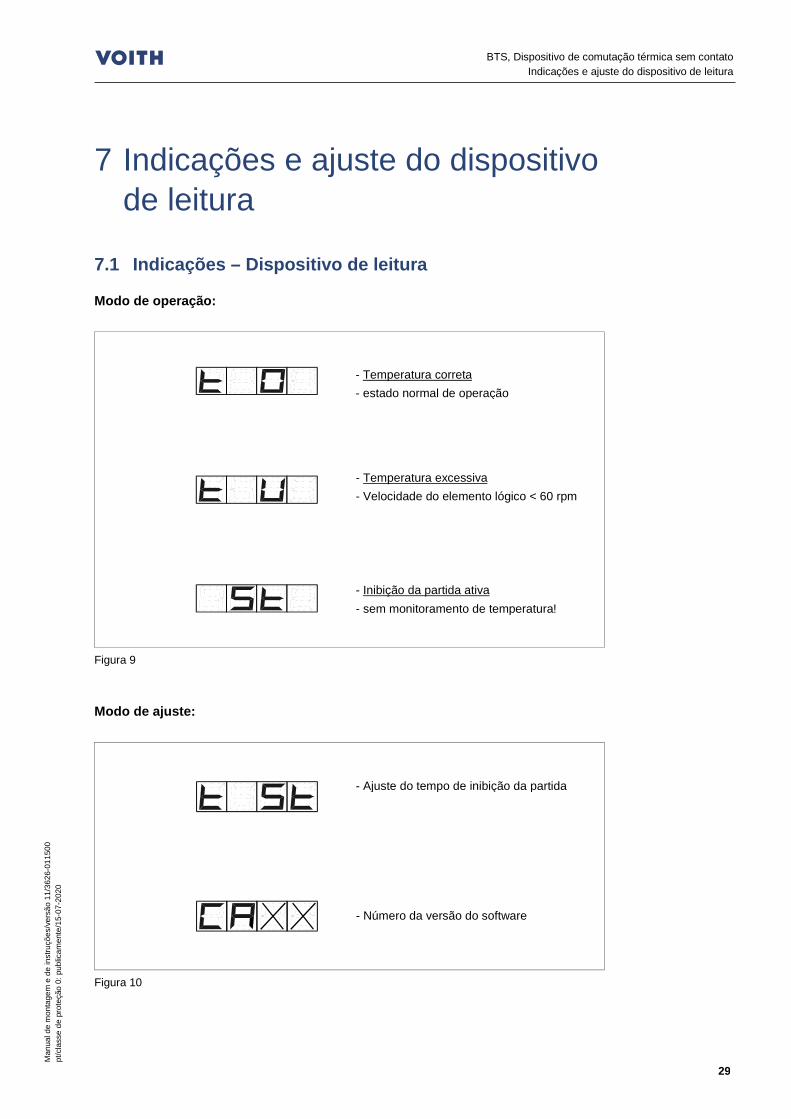
7 Indicações e ajuste do dispositivo de leitura
7.1 Indicações – Dispositivo de leitura Modo de operação:
Figura 9 Modo de ajuste:
Figura 10
- Temperatura correta - estado normal de operação
- Temperatura excessiva - Velocidade do elemento lógico < 60 rpm
- Inibição da partida ativa - sem monitoramento de temperatura!
- Ajuste do tempo de inibição da partida
- Número da versão do software
BTS, Dispositivo de comutação térmica sem contato Indicações e ajuste do dispositivo de leitura
Man
ual d
e m
onta
gem
e d
e in
stru
ções
/ver
são
11/3
626-
0115
00
pt/c
lass
e de
pro
teçã
o 0:
pub
licam
ente
/15-
07-2
020
30
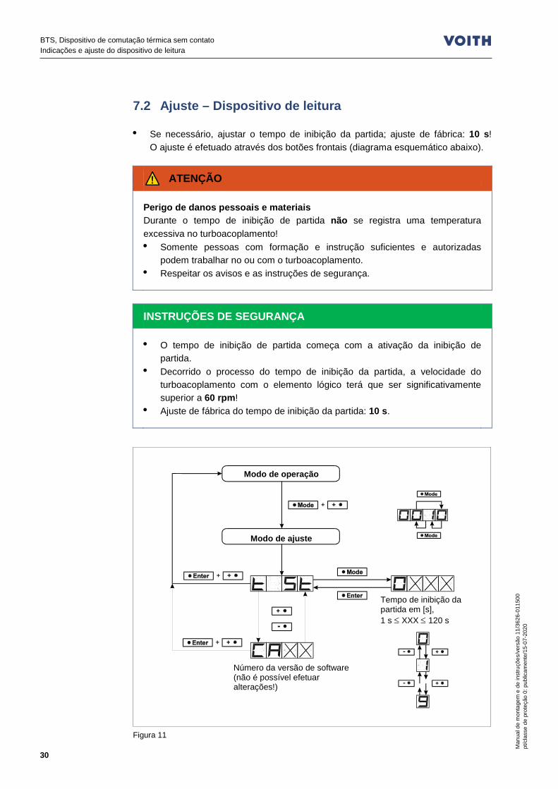
7.2 Ajuste – Dispositivo de leitura • Se necessário, ajustar o tempo de inibição da partida; ajuste de fábrica: 10 s!
O ajuste é efetuado através dos botões frontais (diagrama esquemático abaixo).
ATENÇÃO
Perigo de danos pessoais e materiais Durante o tempo de inibição de partida não se registra uma temperatura excessiva no turboacoplamento! • Somente pessoas com formação e instrução suficientes e autorizadas
podem trabalhar no ou com o turboacoplamento. • Respeitar os avisos e as instruções de segurança.
INSTRUÇÕES DE SEGURANÇA
• O tempo de inibição de partida começa com a ativação da inibição de partida.
• Decorrido o processo do tempo de inibição da partida, a velocidade do turboacoplamento com o elemento lógico terá que ser significativamente superior a 60 rpm!
• Ajuste de fábrica do tempo de inibição da partida: 10 s.
Figura 11
Modo de operação
Número da versão de software (não é possível efetuar alterações!)
Tempo de inibição da partida em [s], 1 s ≤ XXX ≤ 120 s
Modo de ajuste
Man
ual d
e m
onta
gem
e d
e in
stru
ções
/ver
são
11/3
626-
0115
00
pt/c
lass
e de
pro
teçã
o 0:
pub
licam
ente
/15-
07-2
020
31
BTS, Dispositivo de comutação térmica sem contato Colocação em serviço
8 Colocação em serviço ATENÇÃO
Perigo de ferimentos Durante os trabalhos no dispositivo de comutação térmico sem contato, observar especialmente o capítulo 5 (Segurança)! • Uma colocação em serviço executada incorretamente pode causar danos
pessoais, materiais ou ambientais! • A execução da colocação em serviço, em especial a primeira partida do
turboacoplamento, somente pode ser efetuada por pessoal técnico especializado!
• Proteja o equipamento contra a ligação inadvertida!
• Verificar a cablagem de acordo com o diagrama elétrico ( capítulo 6.4).
Verificar, em particular, a cablagem correta da tensão de alimentação! • Aplicar a tensão de alimentação no dispositivo de leitura, primeiro sem partida do
turboacoplamento. Durante o período em que a inibição da partida está ativa, o dispositivo indica . O relê de saída está ativo e o LED frontal acende.
• Decorrido o processo do tempo de inibição da partida, o dispositivo indica .
O relê de saída se desliga e o LED frontal se apaga. • Se necessário, ajustar o tempo de inibição da partida segundo o capítulo 7.2. • Em caso de ativação externa, retirar a ponte aplicada de fábrica entre os bornes 2
e 3 no dispositivo de leitura. • Iniciar o BTS normalmente como turboacoplamento. Decorrido o processo do
tempo de inibição da partida, a velocidade do turboacoplamento com o elemento lógico terá que ser significativamente superior a 60 rpm. O dispositivo de leitura indica quando se verifica uma temperatura excessiva. O relê de saída permanece ativo e o LED frontal acende.
• Desligar o acionamento através do turboacoplamento, deixar o BTS pronto para funcionar. Se a velocidade do turboacoplamento com elemento lógico for inferior a 60 rpm, o dispositivo de leitura indica . O relê de saída se desliga e o LED frontal se apaga.
• A operação normal pode ser iniciada. Em caso de danos capítulo 10.
BTS, Dispositivo de comutação térmica sem contato Manutenção, conservação
Man
ual d
e m
onta
gem
e d
e in
stru
ções
/ver
são
11/3
626-
0115
00
pt/c
lass
e de
pro
teçã
o 0:
pub
licam
ente
/15-
07-2
020
32
9 Manutenção, conservação Definição dos trabalhos de manutenção listados abaixo (em conformidade com a norma IEC 60079): Manutenção e conservação: uma combinação de atividades que são executadas para manter um objeto em um estado ou repô-lo em um estado, que cumpra os requisitos das respectivas especificações e que garanta a execução das funções que lhe são exigidas. Inspeção: uma atividade que implica a análise detalhada do objeto, com o objetivo de obter informações fiáveis sobre o estado do referido objeto. Executa-se sem a desmontagem do mesmo ou, se necessário, com uma desmontagem parcial complementada por medidas como, por exemplo, medições. Inspeção visual: uma inspeção no âmbito da qual são detectados erros visíveis, como por exemplo, falta de parafusos, sem recorrer ao uso de dispositivos de acesso ou ferramentas. Inspeção de perto: uma inspeção na qual, além dos aspectos da inspeção visual, são detectados erros como, por exemplo, parafusos soltos, somente detectáveis mediante o uso de dispositivos de acesso como, por exemplo, escadas (se necessário) e ferramentas. Normalmente, esse tipo de verificação não requer a abertura da carcaça ou a desconexão da tensão dos equipamentos. Inspeção detalhada: uma inspeção na qual, para além dos aspectos da inspeção de perto, são detectados erros como, por exemplo, conexões soltas, somente detectáveis através da abertura da carcaça e/ou, se necessário, mediante o uso de ferramentas e dispositivos de teste.
ATENÇÃO
Perigo de ferimentos Durante os trabalhos no dispositivo de comutação térmico sem contato, observar especialmente o capítulo 5 (Segurança)! • Mantenha sempre livres os caminhos de acesso para o turboacoplamento!
– Os trabalhos de conservação e de manutenção somente podem ser efetuados
por pessoal especializado qualificado e autorizado! A qualificação é garantida através da formação e instrução no turboacoplamento.
– No caso de uma conservação e manutenção incorretamente executadas as consequências são possivelmente a morte, ferimentos graves ou leves, danos materiais ou danos ambientais.
Qualificação Capítulo 5.8
Man
ual d
e m
onta
gem
e d
e in
stru
ções
/ver
são
11/3
626-
0115
00
pt/c
lass
e de
pro
teçã
o 0:
pub
licam
ente
/15-
07-2
020
33
BTS, Dispositivo de comutação térmica sem contato Manutenção, conservação
– Desligue o equipamento no qual o turboacoplamento está montado e proteja-o contra nova ligação.
– Sempre que forem efetuados trabalhos no turboacoplamento, certifique-se de que tanto o motor de acionamento como a máquina de serviço estão parados e de que a partida está excluída em quaisquer circunstâncias!
– A substituição de componentes somente deve ser efetuada com peças de reposição originais.
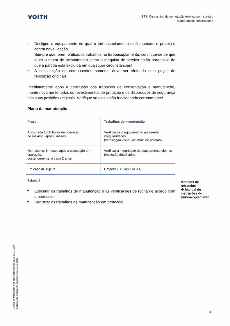
Imediatamente após a conclusão dos trabalhos de conservação e manutenção, monte novamente todos os revestimentos de proteção e os dispositivos de segurança nas suas posições originais. Verifique se eles estão funcionando corretamente! Plano de manutenção:
Prazo Trabalhos de manutenção
Após cada 1000 horas de operação, no máximo, após 6 meses
Verificar se o equipamento apresenta irregularidades (verificação visual, acúmulo de poeiras).
No máximo, 6 meses após a colocação em operação, posteriormente, a cada 2 anos
Verificar a integridade do equipamento elétrico (inspeção detalhada).
Em caso de sujeira Limpeza ( Capítulo 9.1).
Tabela 9 • Executar os trabalhos de manutenção e as verificações de rotina de acordo com
o protocolo. • Registrar os trabalhos de manutenção em protocolo.
Modelos de relatórios Manual de instruções do turboacoplamento
BTS, Dispositivo de comutação térmica sem contato Manutenção, conservação
Man
ual d
e m
onta
gem
e d
e in
stru
ções
/ver
são
11/3
626-
0115
00
pt/c
lass
e de
pro
teçã
o 0:
pub
licam
ente
/15-
07-2
020
34
Nos turboacoplamentos com proteção contra explosão é necessário efetuar ainda os seguintes trabalhos de manutenção:
Intervalos de manutenção Trabalho de manutenção
Em caso de sujeira ou acúmulo de poeira: os dispositivos que estejam em atmosferas potencialmente explosivas têm que ser limpos com regularidade. Os intervalos são definidos pela entidade usuária, de acordo com os impactos ambientais no local, por exemplo, no caso de acúmulo de poeira de cerca de 0,2…0,5 mm ou superior.
Limpeza ( Capítulo 9.1).
Tabela 10
ATENÇÃO
Perigo de explosão Perigo de explosão devido ao incumprimento dos trabalhos de manutenção. É necessário o cumprimento dos trabalhos de acordo com o plano de manutenção, por forma a garantir uma operação devida no âmbito da proteção contra explosão. • Remover de imediato eventuais deposições de poeiras inflamáveis dos
dispositivos.
9.1 Limpeza exterior
NOTA
Danos materiais Danos no BTS devido a uma limpeza incorreta e inadequada do exterior. • Ter atenção à compatibilidade do detergente com a carcaça de plástico do
BTS, bem como com o vedante de borracha da conexão do cabo! • Não utilizar qualquer dispositivo de limpeza de alta pressão! • Manuseie cuidadosamente os vedantes. Evite jatos de água ou de ar
comprimido.
• Se necessário, limpar o BTS com um solvente desengordurante.
Man
ual d
e m
onta
gem
e d
e in
stru
ções
/ver
são
11/3
626-
0115
00
pt/c
lass
e de
pro
teçã
o 0:
pub
licam
ente
/15-
07-2
020
35
BTS, Dispositivo de comutação térmica sem contato Descarte
10 Descarte Descarte da embalagem Descartar o material da embalagem de acordo com as normas locais. Descarte de fluidos de serviço Ao efetuar o descarte, respeitar a respectiva legislação, bem como as indicações do fabricante ou fornecedor. Descarte do BTS Descartar o BTS de acordo com as normas locais. Consulte a seguinte tabela para obter indicações específicas sobre o descarte de substâncias e materiais:
Tipo de descarte
Material/substância Reciclagem Lixo residual Resíduos perigosos
Metais x - -
Cabos x - -
Vedações - x -
Plásticos x 1) (x) -
Equipamentos - - x 1), 2)
Embalagem x - -
Tabela 11
1) se possível 2) descartar de acordo com a folha de dados de segurança ou as indicações do fabricante
BTS, Dispositivo de comutação térmica sem contato Falhas – Soluções, detecção de erros
Man
ual d
e m
onta
gem
e d
e in
stru
ções
/ver
são
11/3
626-
0115
00
pt/c
lass
e de
pro
teçã
o 0:
pub
licam
ente
/15-
07-2
020
36
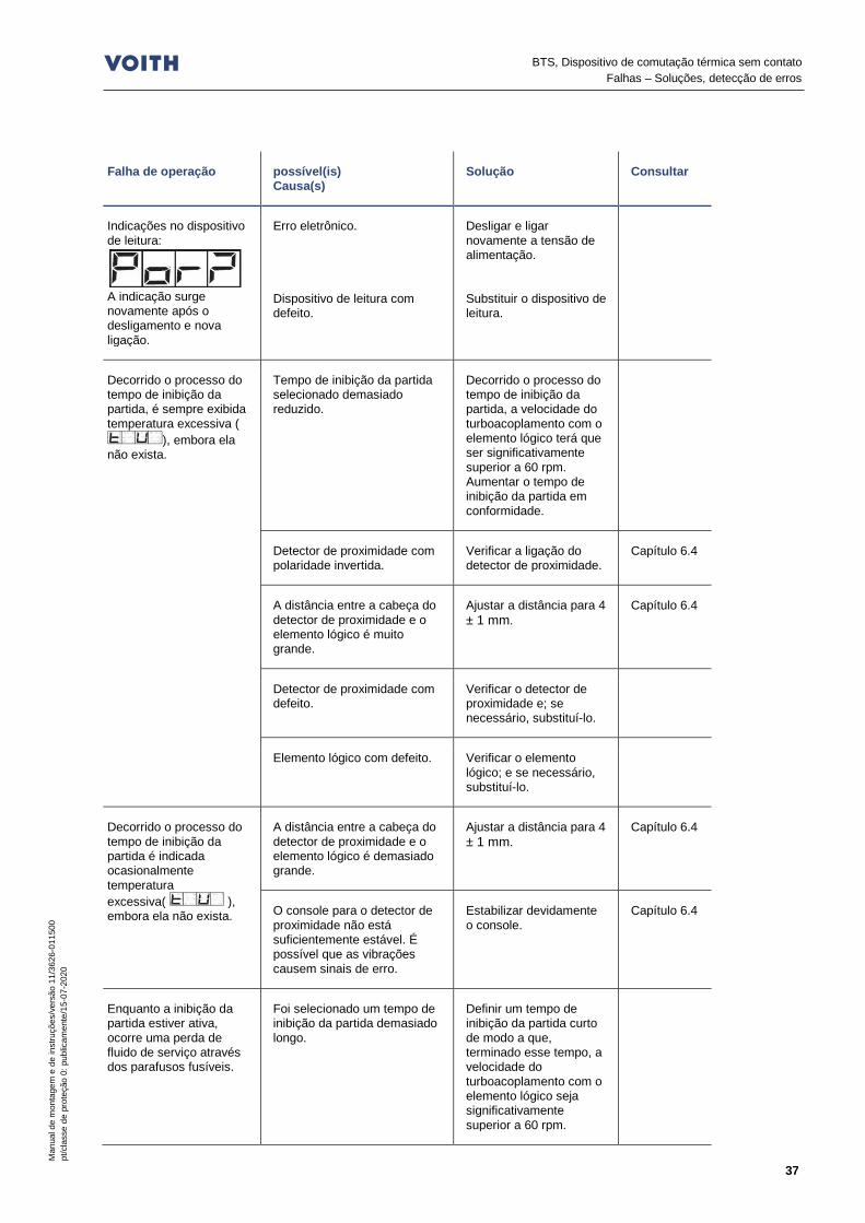
11 Falhas – Soluções, detecção de erros
ATENÇÃO
Perigo de ferimentos Durante os trabalhos no dispositivo de comutação térmico sem contato, observar especialmente o capítulo 5 (Segurança)!
ATENÇÃO
Perigo de explosão Não deve ser efetuada qualquer modificação em dispositivos que sejam usados em atmosferas potencialmente explosivas. • Não são permitidos reparos; tem que ser efetuada uma substituição.
A tabela seguinte irá ajudá-lo a detectar rapidamente a causa de eventuais falhas de operação e, se necessário, a proceder à respectiva resolução.
Falha de operação possível(is) Causa(s)
Solução Consultar
O dispositivo de leitura não tem qualquer indicação.
Dispositivo de leitura sem tensão de alimentação.
Aplicar a tensão de alimentação.
Capítulo 6.4
Dispositivo de leitura com defeito.
Substituir o dispositivo de leitura.
A ativação da inibição da partida por meio da aplicação da tensão de alimentação não funciona.
A ponte entre os bornes 3 e 2 no dispositivo de leitura foi retirada.
Colocar a ponte. Capítulo 6.4
A ativação da inibição da partida através um sinal externo não funciona.
A ponte entre os bornes 3 e 2 no dispositivo de leitura não foi retirada.
Retirar a ponte. Capítulo 6.4
O sinal externo de ativação é demasiado curto.
Acionar o sinal de ativação, pelo menos, durante o tempo de inibição da partida.
Man
ual d
e m
onta
gem
e d
e in
stru
ções
/ver
são
11/3
626-
0115
00
pt/c
lass
e de
pro
teçã
o 0:
pub
licam
ente
/15-
07-2
020
37
BTS, Dispositivo de comutação térmica sem contato Falhas – Soluções, detecção de erros
Falha de operação possível(is) Causa(s)
Solução Consultar
Indicações no dispositivo de leitura:
A indicação surge novamente após o desligamento e nova ligação.
Erro eletrônico. Dispositivo de leitura com defeito.
Desligar e ligar novamente a tensão de alimentação. Substituir o dispositivo de leitura.
Decorrido o processo do tempo de inibição da partida, é sempre exibida temperatura excessiva (
), embora ela não exista.
Tempo de inibição da partida selecionado demasiado reduzido.
Decorrido o processo do tempo de inibição da partida, a velocidade do turboacoplamento com o elemento lógico terá que ser significativamente superior a 60 rpm. Aumentar o tempo de inibição da partida em conformidade.
Detector de proximidade com polaridade invertida.
Verificar a ligação do detector de proximidade.
Capítulo 6.4
A distância entre a cabeça do detector de proximidade e o elemento lógico é muito grande.
Ajustar a distância para 4 ± 1 mm.
Capítulo 6.4
Detector de proximidade com defeito.
Verificar o detector de proximidade e; se necessário, substituí-lo.
Elemento lógico com defeito. Verificar o elemento lógico; e se necessário, substituí-lo.
Decorrido o processo do tempo de inibição da partida é indicada ocasionalmente temperatura excessiva( ), embora ela não exista.
A distância entre a cabeça do detector de proximidade e o elemento lógico é demasiado grande.
Ajustar a distância para 4 ± 1 mm.
Capítulo 6.4
O console para o detector de proximidade não está suficientemente estável. É possível que as vibrações causem sinais de erro.
Estabilizar devidamente o console.
Capítulo 6.4
Enquanto a inibição da partida estiver ativa, ocorre uma perda de fluido de serviço através dos parafusos fusíveis.
Foi selecionado um tempo de inibição da partida demasiado longo.
Definir um tempo de inibição da partida curto de modo a que, terminado esse tempo, a velocidade do turboacoplamento com o elemento lógico seja significativamente superior a 60 rpm.
BTS, Dispositivo de comutação térmica sem contato Falhas – Soluções, detecção de erros
Man
ual d
e m
onta
gem
e d
e in
stru
ções
/ver
são
11/3
626-
0115
00
pt/c
lass
e de
pro
teçã
o 0:
pub
licam
ente
/15-
07-2
020
38
Falha de operação possível(is) Causa(s)
Solução Consultar
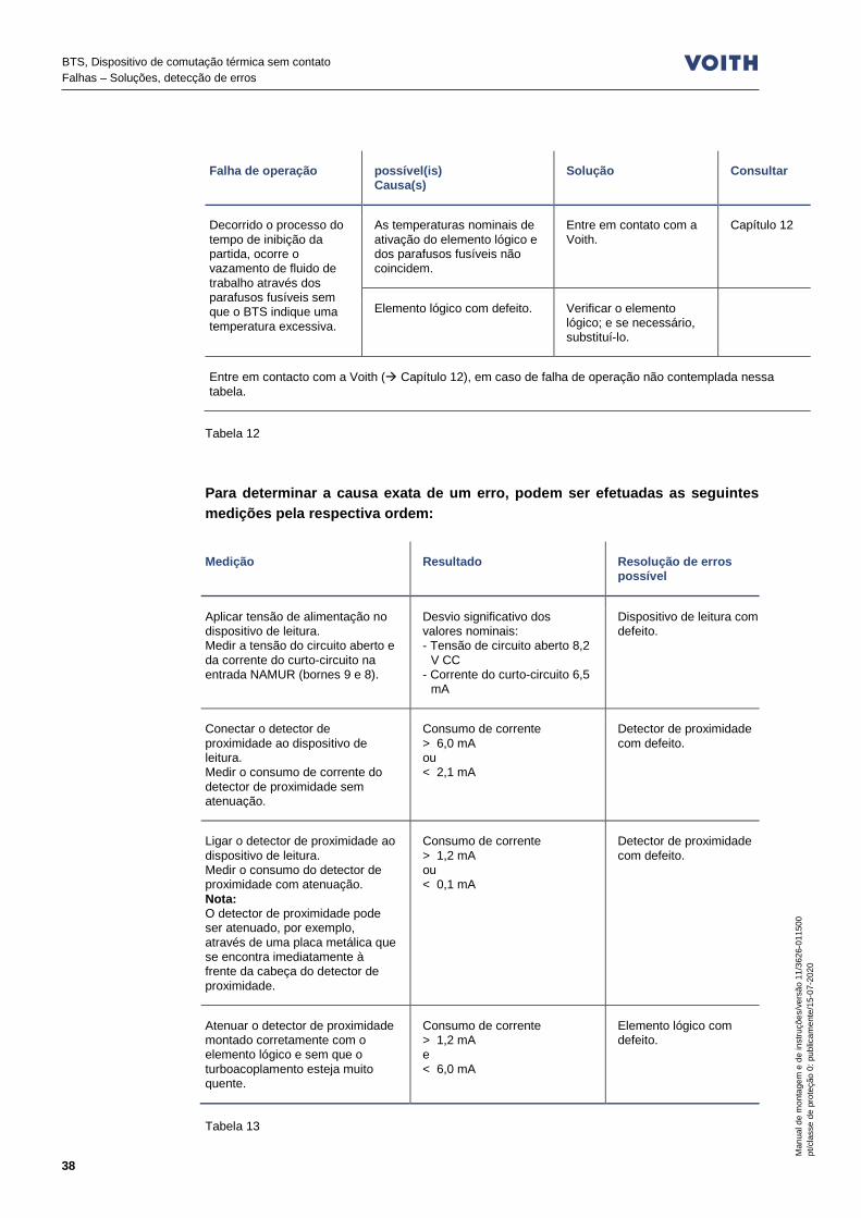
Decorrido o processo do tempo de inibição da partida, ocorre o vazamento de fluido de trabalho através dos parafusos fusíveis sem que o BTS indique uma temperatura excessiva.
As temperaturas nominais de ativação do elemento lógico e dos parafusos fusíveis não coincidem.
Entre em contato com a Voith.
Capítulo 12
Elemento lógico com defeito. Verificar o elemento lógico; e se necessário, substituí-lo.
Entre em contacto com a Voith ( Capítulo 12), em caso de falha de operação não contemplada nessa tabela.
Tabela 12 Para determinar a causa exata de um erro, podem ser efetuadas as seguintes medições pela respectiva ordem:
Medição Resultado Resolução de erros possível
Aplicar tensão de alimentação no dispositivo de leitura. Medir a tensão do circuito aberto e da corrente do curto-circuito na entrada NAMUR (bornes 9 e 8).
Desvio significativo dos valores nominais: - Tensão de circuito aberto 8,2
V CC - Corrente do curto-circuito 6,5
mA
Dispositivo de leitura com defeito.
Conectar o detector de proximidade ao dispositivo de leitura. Medir o consumo de corrente do detector de proximidade sem atenuação.
Consumo de corrente > 6,0 mA ou < 2,1 mA
Detector de proximidade com defeito.
Ligar o detector de proximidade ao dispositivo de leitura. Medir o consumo do detector de proximidade com atenuação. Nota: O detector de proximidade pode ser atenuado, por exemplo, através de uma placa metálica que se encontra imediatamente à frente da cabeça do detector de proximidade.
Consumo de corrente > 1,2 mA ou < 0,1 mA
Detector de proximidade com defeito.
Atenuar o detector de proximidade montado corretamente com o elemento lógico e sem que o turboacoplamento esteja muito quente.
Consumo de corrente > 1,2 mA e < 6,0 mA
Elemento lógico com defeito.
Tabela 13
Man
ual d
e m
onta
gem
e d
e in
stru
ções
/ver
são
11/3
626-
0115
00
pt/c
lass
e de
pro
teçã
o 0:
pub
licam
ente
/15-
07-2
020
39
BTS, Dispositivo de comutação térmica sem contato Pedidos de informações, solicitação de um técnico e de peças de reposição
12 Pedidos de informações, solicitação de um técnico e de peças de reposição
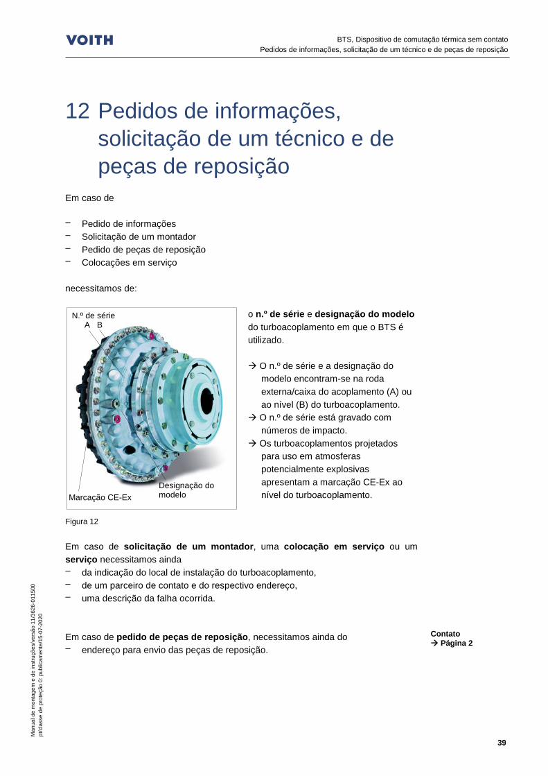
Em caso de – Pedido de informações – Solicitação de um montador – Pedido de peças de reposição – Colocações em serviço necessitamos de:
Figura 12
o n.º de série e designação do modelo do turboacoplamento em que o BTS é utilizado. O n.º de série e a designação do
modelo encontram-se na roda externa/caixa do acoplamento (A) ou ao nível (B) do turboacoplamento.
O n.º de série está gravado com números de impacto.
Os turboacoplamentos projetados para uso em atmosferas potencialmente explosivas apresentam a marcação CE-Ex ao nível do turboacoplamento.
Em caso de solicitação de um montador, uma colocação em serviço ou um serviço necessitamos ainda – da indicação do local de instalação do turboacoplamento, – de um parceiro de contato e do respectivo endereço, – uma descrição da falha ocorrida. Em caso de pedido de peças de reposição, necessitamos ainda do – endereço para envio das peças de reposição.
Contato Página 2
Designação do modelo Marcação CE-Ex
N.º de série A B
BTS, Dispositivo de comutação térmica sem contato Informações sobre peças de reposição
Man
ual d
e m
onta
gem
e d
e in
stru
ções
/ver
são
11/3
626-
0115
00
pt/c
lass
e de
pro
teçã
o 0:
pub
licam
ente
/15-
07-2
020
40
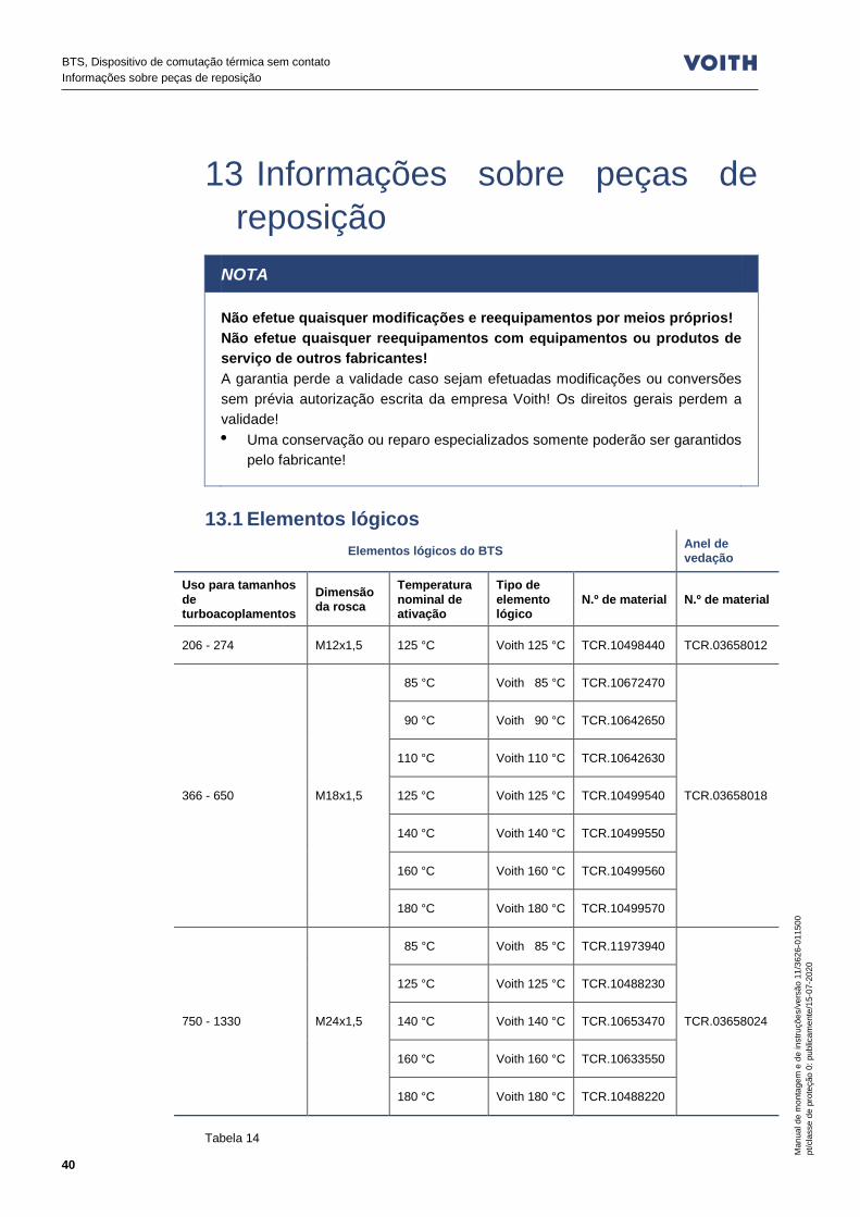
13 Informações sobre peças de reposição
NOTA
Não efetue quaisquer modificações e reequipamentos por meios próprios! Não efetue quaisquer reequipamentos com equipamentos ou produtos de serviço de outros fabricantes! A garantia perde a validade caso sejam efetuadas modificações ou conversões sem prévia autorização escrita da empresa Voith! Os direitos gerais perdem a validade! • Uma conservação ou reparo especializados somente poderão ser garantidos
pelo fabricante!
13.1 Elementos lógicos
Elementos lógicos do BTS Anel de vedação
Uso para tamanhos de turboacoplamentos
Dimensão da rosca
Temperatura nominal de ativação
Tipo de elemento lógico
N.º de material N.º de material
206 - 274 M12x1,5 125 °C Voith 125 °C TCR.10498440 TCR.03658012
366 - 650 M18x1,5
85 °C Voith 85 °C TCR.10672470
TCR.03658018
90 °C Voith 90 °C TCR.10642650
110 °C Voith 110 °C TCR.10642630
125 °C Voith 125 °C TCR.10499540
140 °C Voith 140 °C TCR.10499550
160 °C Voith 160 °C TCR.10499560
180 °C Voith 180 °C TCR.10499570
750 - 1330 M24x1,5
85 °C Voith 85 °C TCR.11973940
TCR.03658024
125 °C Voith 125 °C TCR.10488230
140 °C Voith 140 °C TCR.10653470
160 °C Voith 160 °C TCR.10633550
180 °C Voith 180 °C TCR.10488220
Tabela 14
Man
ual d
e m
onta
gem
e d
e in
stru
ções
/ver
são
11/3
626-
0115
00
pt/c
lass
e de
pro
teçã
o 0:
pub
licam
ente
/15-
07-2
020
41
BTS, Dispositivo de comutação térmica sem contato Informações sobre peças de reposição
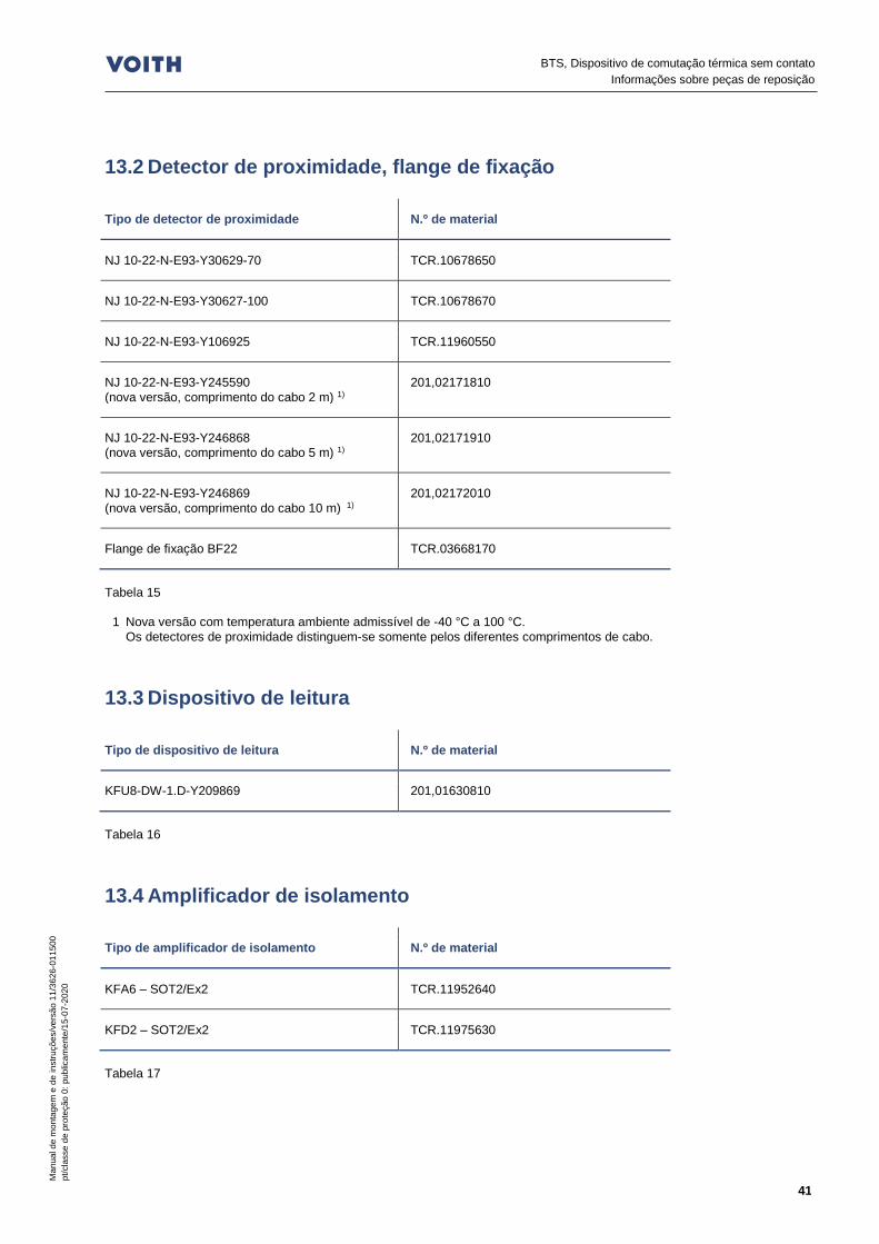
13.2 Detector de proximidade, flange de fixação
Tipo de detector de proximidade N.º de material
NJ 10-22-N-E93-Y30629-70 TCR.10678650
NJ 10-22-N-E93-Y30627-100 TCR.10678670
NJ 10-22-N-E93-Y106925 TCR.11960550
NJ 10-22-N-E93-Y245590 (nova versão, comprimento do cabo 2 m) 1)
201,02171810
NJ 10-22-N-E93-Y246868 (nova versão, comprimento do cabo 5 m) 1)
201,02171910
NJ 10-22-N-E93-Y246869 (nova versão, comprimento do cabo 10 m) 1)
201,02172010
Flange de fixação BF22 TCR.03668170
Tabela 15
1 Nova versão com temperatura ambiente admissível de -40 °C a 100 °C. Os detectores de proximidade distinguem-se somente pelos diferentes comprimentos de cabo.
13.3 Dispositivo de leitura
Tipo de dispositivo de leitura N.º de material
KFU8-DW-1.D-Y209869 201,01630810
Tabela 16 13.4 Amplificador de isolamento
Tipo de amplificador de isolamento N.º de material
KFA6 – SOT2/Ex2 TCR.11952640
KFD2 – SOT2/Ex2 TCR.11975630
Tabela 17
BTS, Dispositivo de comutação térmica sem contato Anexo
Man
ual d
e m
onta
gem
e d
e in
stru
ções
/ver
são
11/3
626-
0115
00
pt/c
lass
e de
pro
teçã
o 0:
pub
licam
ente
/15-
07-2
020
42
14 Anexo 14.1 Detector de proximidade NJ10-22-N-E93-Y106925 Manual de instruções Pepperl+Fuchs Dados técnicos Pepperl+Fuchs Declaração de conformidade Pepperl+Fuchs

1 / 1TDOCT-4177BENG / 2017-02
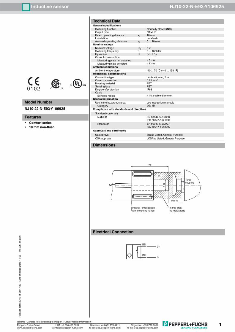
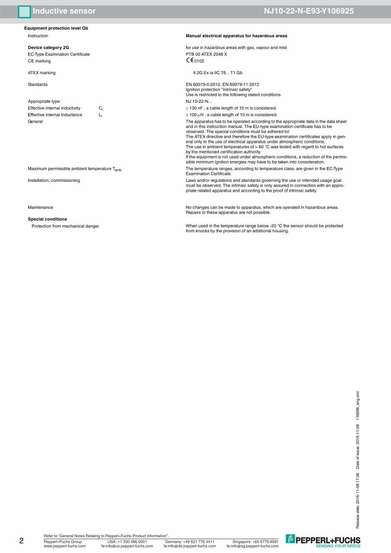
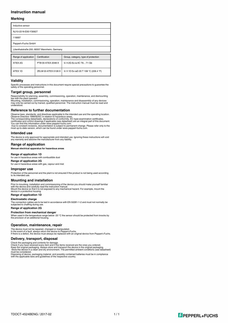
Instruction manualMarking
Inductive sensor
NJ10-22-N-E93-Y106925
116696
Pepperl+Fuchs GmbH
Lilienthalstraße 200, 68307 Mannheim, Germany
Range of application Certification Group, category, type of protection
ATEX 2G PTB 00 ATEX 2048 X e II 2G Ex ia IIC T6…T1 Gb
ATEX 1D ZELM 03 ATEX 0128 X e II 1D Ex iaD 20 T 85 °C (185 °F)
ValiditySpecific processes and instructions in this document require special precautions to guarantee thesafety of the operating personnel.
Target group, personnelResponsibility for planning, assembly, commissioning, operation, maintenance, and dismountinglies with the plant operator.Mounting, installation, commissioning, operation, maintenance and disassembly of any devicesmay only be carried out by trained, qualified personnel. The instruction manual must be read andunderstood.
Reference to further documentationObserve laws, standards, and directives applicable to the intended use and the operating location.Observe Directive 1999/92/EC in relation to hazardous areas.The corresponding datasheets, declarations of conformity, EC-type-examination certificates,certificates and control drawings if applicable (see datasheet) are an integral part of this document.You can find this information under www.pepperl-fuchs.com. Due to constant revisions, documentation is subject to permanent change. Please refer only to themost up-to-date version, which can be found under www.pepperl-fuchs.com.
Intended useThe device is only approved for appropriate and intended use. Ignoring these instructions will voidany warranty and absolve the manufacturer from any liability.
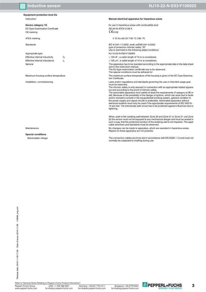
Range of applicationManual electrical apparatus for hazardous areas
Range of application 1Dfor use in hazardous areas with combustible dustRange of application 2Gfor use in hazardous areas with gas, vapour and mist
Improper useProtection of the personnel and the plant is not ensured if the product is not being used accordingto its intended use.
Mounting and installationPrior to mounting, installation and commissioning of the device you should make yourself familiarwith the device and carefully read the instruction manual.Mount the device so that it is not exposed to any mechanical hazard. For example, mount thedevice in a protective housing.Range of application 1DElectrostatic chargeThe connection cables are to be laid in accordance with EN 50281-1-2 and must not normally besubjected to chaffing during use.Range of application 2GProtection from mechanical dangerWhen used in the temperature range below -20 °C the sensor should be protected from knocks bythe provision of an additional housing.
Operation, maintenance, repairThe device must not be repaired, changed or manipulated.In the event of a fault, always return the device to Pepperl+Fuchs.If there is a defect, the device must always be replaced with an original device from Pepperl+Fuchs.
Delivery, transport, disposalCheck the packaging and contents for damage.Check if you have received every item and if the items received are the ones you ordered.Keep the original packaging. Always store and transport the device in the original packaging. Store the device in a clean and dry environment. The permitted ambient conditions (see datasheet)must be considered.Disposing of device, packaging material, and possibly contained batteries must be in compliancewith the applicable laws and guidelines of the respective country.

DOC-1582 / 2017-04-11 1/1
EU-Declaration of conformity
EU-Konformitätserklärung
Pepperl+Fuchs GmbH
Lilienthalstraße 200
68307 Mannheim
Germany
Phone +49 621 776-0
Fax +49 621 776-1000 No. / Nr.: DOC-1582
Date / Datum: 2017-04-11
Copyright Pepperl+Fuchs
www.pepperl-fuchs.com
Declaration of conformity / Konformitätserklärung
We, Pepperl+Fuchs GmbH declare under our sole responsibility that the
products listed below are in conformity with the listed European Direc-
tives and standards.
Die Pepperl+Fuchs GmbH erklärt hiermit in alleiniger Verantwortung,
dass die unten gelisteten Produkte den genannten Europäischen
Richtlinien und Normen entsprechen.
Products / Produkte
Product / Produkt Item number
Description / Beschrei-bung
NJ10-22-N-E93-Y106925 116696 Inductive sensor
NJ10-22-N-E93-Y30627 116697 Inductive sensor
NJ10-22-N-E93-Y30629 116698 Inductive sensor
NJ10-22-N-E93-Y52737 116699 Inductive sensor
Directives and Standards / Richtlinien und Normen
EU-Directive EU-Richtlinie
Standards Normen
ATEX 2014/34/EU (L96/309-356)
EN 60079-0/A11:2013-11 EN 60079-0:2012-08 EN 60079-11:2012-01 prEN 61241-0:2002-04
EMC 2014/30/EU (L96/79-106)
EN 60947-5-2/A1:2012-11 EN 60947-5-2:2007-12 EN 60947-5-6:2000-01
RoHS 2011/65/EU (L174/88–110)
EN 50581:2012-09
Affixed CE Marking / Angebrachte CE-Kennzeichnung
0102
Signatures / Unterschriften
Mannheim, 2017-04-11
ppa. Wolfgang Helm i.V. Tobias Dittmer
Director Business Unit Sensors Global Product Manager
ANNEX ATEX
Notified Body QM-System / Notifizierte Stelle des QM-Systems Physikalisch Technische Bundesanstalt (0102) Bundesallee 100 38116 Braunschweig Germany
Marking and Certificates / Kennzeichnung und Zertifikate
Marking Kennzeichnung
Certificate Zertifikat
Issuer ID Aussteller ID
II 2 G PTB 00 ATEX 2048 X 0102
II 1 D ZELM 03 ATEX 0128 X 0820
Key for Issuer ID / Schlüssel zur Aussteller ID
ID Issuer / Aussteller
0820 ZELM ex Siekgraben 56 38124 Braunschweig Germany
0102 Physikalisch Technische Bundesanstalt Bundesallee 100 38116 Braunschweig Germany
Pepperl+Fuchs GmbH declares that the products are only affected by minor or formal changes with respect to the new edition of the stand-ards. These changes are not relevant for compliance with the essential health and safety requirements. The products still comply with the ATEX Directive. This declaration is also valid if the marking and the cer-tificates of the listed devices correspond to previous editions of stand-ards. Die Pepperl+Fuchs GmbH erklärt hiermit, dass die Produkte nur von kleineren oder formalen Änderungen in Bezug auf die neue Ausgabe der Normen betroffen sind. Diese Änderungen sind nicht relevant für die Konformität mit den wesentlichen Gesundheits- und Sicherheitsanforde-rungen. Die Produkte erfüllen nach wie vor die ATEX-Richtlinie. Diese Erklärung gilt auch, wenn die Kennzeichnung und die Zertifikate der aufgeführten Geräte vorangegangenen Normenständen entsprechen.
en/de

Man
ual d
e m
onta
gem
e d
e in
stru
ções
/ver
são
11/3
626-
0115
00
pt/c
lass
e de
pro
teçã
o 0:
pub
licam
ente
/15-
07-2
020
43
BTS, Dispositivo de comutação térmica sem contato Anexo
14.2 Detector de proximidade NJ10-22-N-E93-Y30627 Manual de instruções Pepperl+Fuchs Dados técnicos Pepperl+Fuchs Declaração de conformidade Pepperl+Fuchs
1 / 1TDOCT-4524BENG / 2017-02
Instruction manualMarking
Inductive sensor
NJ10-22-N-E93-Y30627
116697
Pepperl+Fuchs GmbH
Lilienthalstraße 200, 68307 Mannheim, Germany
Range of application Certification Group, category, type of protection
ATEX 2G PTB 00 ATEX 2048 X e II 2G Ex ia IIC T6…T1 Gb
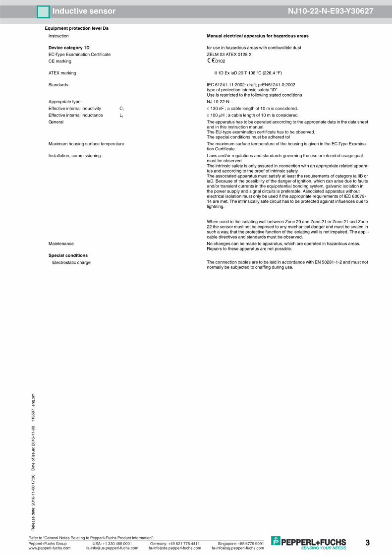
ATEX 1D ZELM 03 ATEX 0128 X e II 1D Ex iaD 20 T 108 °C (226.4 °F)
ValiditySpecific processes and instructions in this document require special precautions to guarantee thesafety of the operating personnel.
Target group, personnelResponsibility for planning, assembly, commissioning, operation, maintenance, and dismountinglies with the plant operator.Mounting, installation, commissioning, operation, maintenance and disassembly of any devicesmay only be carried out by trained, qualified personnel. The instruction manual must be read andunderstood.
Reference to further documentationObserve laws, standards, and directives applicable to the intended use and the operating location.Observe Directive 1999/92/EC in relation to hazardous areas.The corresponding datasheets, declarations of conformity, EC-type-examination certificates,certificates and control drawings if applicable (see datasheet) are an integral part of this document.You can find this information under www.pepperl-fuchs.com. Due to constant revisions, documentation is subject to permanent change. Please refer only to themost up-to-date version, which can be found under www.pepperl-fuchs.com.
Intended useThe device is only approved for appropriate and intended use. Ignoring these instructions will voidany warranty and absolve the manufacturer from any liability.
Range of applicationManual electrical apparatus for hazardous areas
Range of application 1Dfor use in hazardous areas with combustible dustRange of application 2Gfor use in hazardous areas with gas, vapour and mist
Improper useProtection of the personnel and the plant is not ensured if the product is not being used accordingto its intended use.
Mounting and installationPrior to mounting, installation and commissioning of the device you should make yourself familiarwith the device and carefully read the instruction manual.Mount the device so that it is not exposed to any mechanical hazard. For example, mount thedevice in a protective housing.Range of application 1DElectrostatic chargeThe connection cables are to be laid in accordance with EN 50281-1-2 and must not normally besubjected to chaffing during use.Range of application 2GProtection from mechanical dangerWhen used in the temperature range below -20 °C the sensor should be protected from knocks bythe provision of an additional housing.
Operation, maintenance, repairThe device must not be repaired, changed or manipulated.In the event of a fault, always return the device to Pepperl+Fuchs.If there is a defect, the device must always be replaced with an original device from Pepperl+Fuchs.
Delivery, transport, disposalCheck the packaging and contents for damage.Check if you have received every item and if the items received are the ones you ordered.Keep the original packaging. Always store and transport the device in the original packaging. Store the device in a clean and dry environment. The permitted ambient conditions (see datasheet)must be considered.Disposing of device, packaging material, and possibly contained batteries must be in compliancewith the applicable laws and guidelines of the respective country.


DOC-1582 / 2017-04-11 1/1
EU-Declaration of conformity
EU-Konformitätserklärung
Pepperl+Fuchs GmbH
Lilienthalstraße 200
68307 Mannheim
Germany
Phone +49 621 776-0
Fax +49 621 776-1000 No. / Nr.: DOC-1582
Date / Datum: 2017-04-11
Copyright Pepperl+Fuchs
www.pepperl-fuchs.com
Declaration of conformity / Konformitätserklärung
We, Pepperl+Fuchs GmbH declare under our sole responsibility that the
products listed below are in conformity with the listed European Direc-
tives and standards.
Die Pepperl+Fuchs GmbH erklärt hiermit in alleiniger Verantwortung,
dass die unten gelisteten Produkte den genannten Europäischen
Richtlinien und Normen entsprechen.
Products / Produkte
Product / Produkt Item number
Description / Beschrei-bung
NJ10-22-N-E93-Y106925 116696 Inductive sensor
NJ10-22-N-E93-Y30627 116697 Inductive sensor
NJ10-22-N-E93-Y30629 116698 Inductive sensor
NJ10-22-N-E93-Y52737 116699 Inductive sensor
Directives and Standards / Richtlinien und Normen
EU-Directive EU-Richtlinie
Standards Normen
ATEX 2014/34/EU (L96/309-356)
EN 60079-0/A11:2013-11 EN 60079-0:2012-08 EN 60079-11:2012-01 prEN 61241-0:2002-04
EMC 2014/30/EU (L96/79-106)
EN 60947-5-2/A1:2012-11 EN 60947-5-2:2007-12 EN 60947-5-6:2000-01
RoHS 2011/65/EU (L174/88–110)
EN 50581:2012-09
Affixed CE Marking / Angebrachte CE-Kennzeichnung
0102
Signatures / Unterschriften
Mannheim, 2017-04-11
ppa. Wolfgang Helm i.V. Tobias Dittmer
Director Business Unit Sensors Global Product Manager
ANNEX ATEX
Notified Body QM-System / Notifizierte Stelle des QM-Systems Physikalisch Technische Bundesanstalt (0102) Bundesallee 100 38116 Braunschweig Germany
Marking and Certificates / Kennzeichnung und Zertifikate
Marking Kennzeichnung
Certificate Zertifikat
Issuer ID Aussteller ID
II 2 G PTB 00 ATEX 2048 X 0102
II 1 D ZELM 03 ATEX 0128 X 0820
Key for Issuer ID / Schlüssel zur Aussteller ID
ID Issuer / Aussteller
0820 ZELM ex Siekgraben 56 38124 Braunschweig Germany
0102 Physikalisch Technische Bundesanstalt Bundesallee 100 38116 Braunschweig Germany
Pepperl+Fuchs GmbH declares that the products are only affected by minor or formal changes with respect to the new edition of the stand-ards. These changes are not relevant for compliance with the essential health and safety requirements. The products still comply with the ATEX Directive. This declaration is also valid if the marking and the cer-tificates of the listed devices correspond to previous editions of stand-ards. Die Pepperl+Fuchs GmbH erklärt hiermit, dass die Produkte nur von kleineren oder formalen Änderungen in Bezug auf die neue Ausgabe der Normen betroffen sind. Diese Änderungen sind nicht relevant für die Konformität mit den wesentlichen Gesundheits- und Sicherheitsanforde-rungen. Die Produkte erfüllen nach wie vor die ATEX-Richtlinie. Diese Erklärung gilt auch, wenn die Kennzeichnung und die Zertifikate der aufgeführten Geräte vorangegangenen Normenständen entsprechen.
en/de

BTS, Dispositivo de comutação térmica sem contato Anexo
Man
ual d
e m
onta
gem
e d
e in
stru
ções
/ver
são
11/3
626-
0115
00
pt/c
lass
e de
pro
teçã
o 0:
pub
licam
ente
/15-
07-2
020
44
14.3 Detector de proximidade NJ10-22-N-E93-Y30629 Manual de instruções Pepperl+Fuchs Dados técnicos Pepperl+Fuchs Declaração de conformidade Pepperl+Fuchs

1 / 1TDOCT-4665BENG / 2017-02
Instruction manualMarking
Inductive sensor
NJ10-22-N-E93-Y30629
116698
Pepperl+Fuchs GmbH
Lilienthalstraße 200, 68307 Mannheim, Germany
Range of application Certification Group, category, type of protection
ATEX 2G PTB 00 ATEX 2048 X e II 2G Ex ia IIC T6…T1 Gb
ATEX 1D ZELM 03 ATEX 0128 X e II 1D Ex iaD 20 T 85 °C (185 °F)
ValiditySpecific processes and instructions in this document require special precautions to guarantee thesafety of the operating personnel.
Target group, personnelResponsibility for planning, assembly, commissioning, operation, maintenance, and dismountinglies with the plant operator.Mounting, installation, commissioning, operation, maintenance and disassembly of any devicesmay only be carried out by trained, qualified personnel. The instruction manual must be read andunderstood.
Reference to further documentationObserve laws, standards, and directives applicable to the intended use and the operating location.Observe Directive 1999/92/EC in relation to hazardous areas.The corresponding datasheets, declarations of conformity, EC-type-examination certificates,certificates and control drawings if applicable (see datasheet) are an integral part of this document.You can find this information under www.pepperl-fuchs.com. Due to constant revisions, documentation is subject to permanent change. Please refer only to themost up-to-date version, which can be found under www.pepperl-fuchs.com.
Intended useThe device is only approved for appropriate and intended use. Ignoring these instructions will voidany warranty and absolve the manufacturer from any liability.
Range of applicationManual electrical apparatus for hazardous areas
Range of application 1Dfor use in hazardous areas with combustible dustRange of application 2Gfor use in hazardous areas with gas, vapour and mist
Improper useProtection of the personnel and the plant is not ensured if the product is not being used accordingto its intended use.
Mounting and installationPrior to mounting, installation and commissioning of the device you should make yourself familiarwith the device and carefully read the instruction manual.Mount the device so that it is not exposed to any mechanical hazard. For example, mount thedevice in a protective housing.Range of application 1DElectrostatic chargeThe connection cables are to be laid in accordance with EN 50281-1-2 and must not normally besubjected to chaffing during use.Range of application 2GProtection from mechanical dangerWhen used in the temperature range below -20 °C the sensor should be protected from knocks bythe provision of an additional housing.
Operation, maintenance, repairThe device must not be repaired, changed or manipulated.In the event of a fault, always return the device to Pepperl+Fuchs.If there is a defect, the device must always be replaced with an original device from Pepperl+Fuchs.
Delivery, transport, disposalCheck the packaging and contents for damage.Check if you have received every item and if the items received are the ones you ordered.Keep the original packaging. Always store and transport the device in the original packaging. Store the device in a clean and dry environment. The permitted ambient conditions (see datasheet)must be considered.Disposing of device, packaging material, and possibly contained batteries must be in compliancewith the applicable laws and guidelines of the respective country.
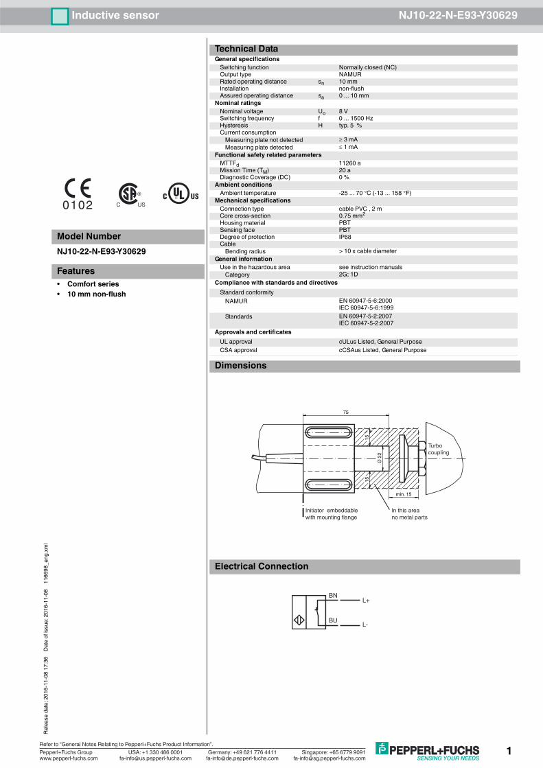
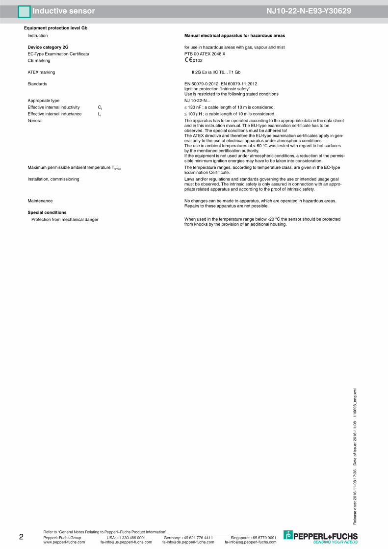
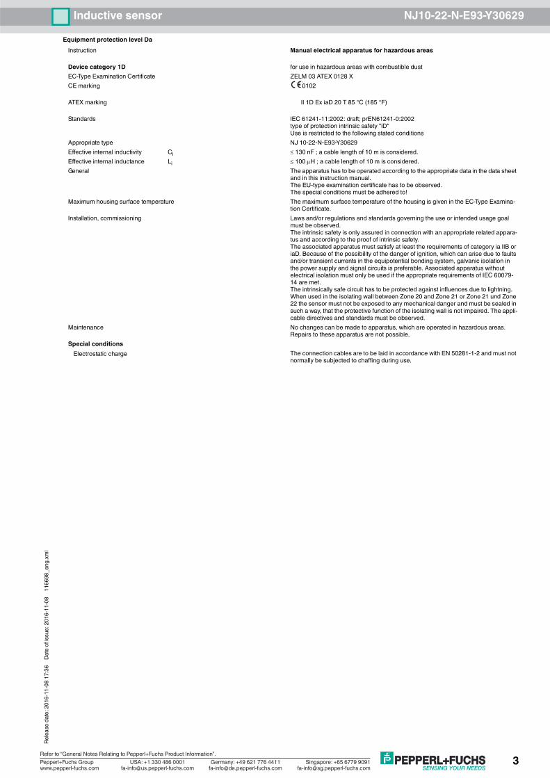
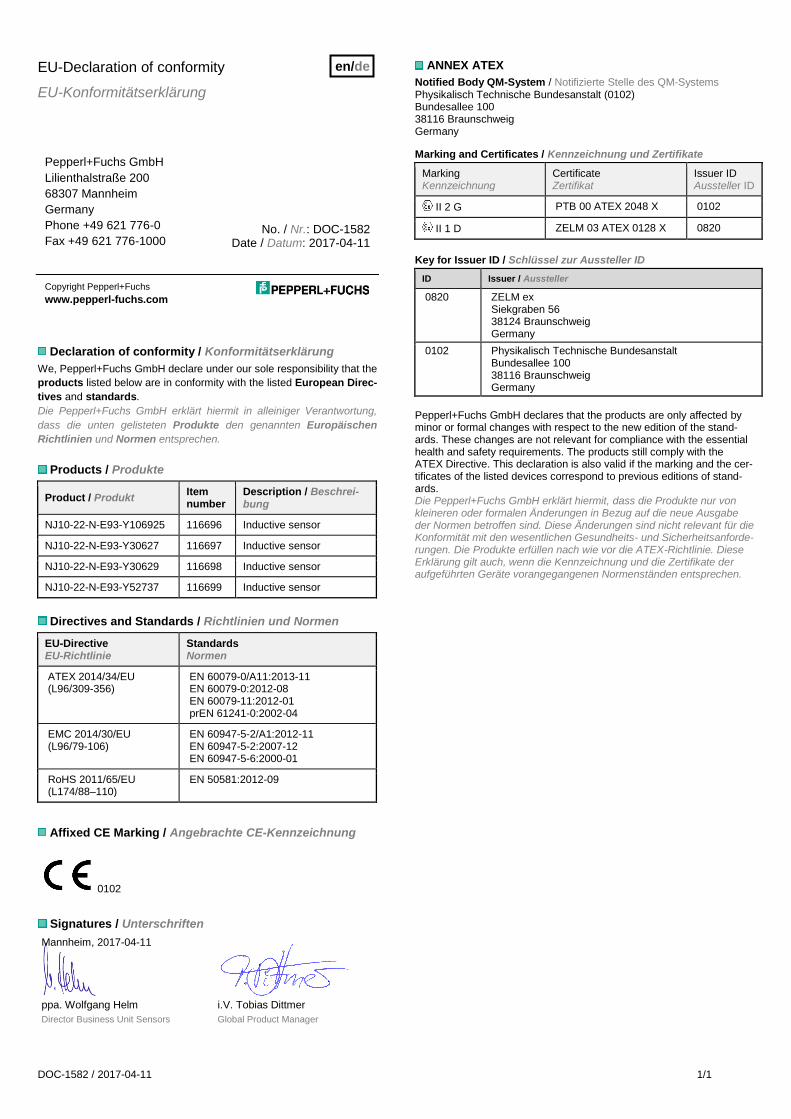
DOC-1582 / 2017-04-11 1/1
EU-Declaration of conformity
EU-Konformitätserklärung
Pepperl+Fuchs GmbH
Lilienthalstraße 200
68307 Mannheim
Germany
Phone +49 621 776-0
Fax +49 621 776-1000 No. / Nr.: DOC-1582
Date / Datum: 2017-04-11
Copyright Pepperl+Fuchs
www.pepperl-fuchs.com
Declaration of conformity / Konformitätserklärung
We, Pepperl+Fuchs GmbH declare under our sole responsibility that the
products listed below are in conformity with the listed European Direc-
tives and standards.
Die Pepperl+Fuchs GmbH erklärt hiermit in alleiniger Verantwortung,
dass die unten gelisteten Produkte den genannten Europäischen
Richtlinien und Normen entsprechen.
Products / Produkte
Product / Produkt Item number
Description / Beschrei-bung
NJ10-22-N-E93-Y106925 116696 Inductive sensor
NJ10-22-N-E93-Y30627 116697 Inductive sensor
NJ10-22-N-E93-Y30629 116698 Inductive sensor
NJ10-22-N-E93-Y52737 116699 Inductive sensor
Directives and Standards / Richtlinien und Normen
EU-Directive EU-Richtlinie
Standards Normen
ATEX 2014/34/EU (L96/309-356)
EN 60079-0/A11:2013-11 EN 60079-0:2012-08 EN 60079-11:2012-01 prEN 61241-0:2002-04
EMC 2014/30/EU (L96/79-106)
EN 60947-5-2/A1:2012-11 EN 60947-5-2:2007-12 EN 60947-5-6:2000-01
RoHS 2011/65/EU (L174/88–110)
EN 50581:2012-09
Affixed CE Marking / Angebrachte CE-Kennzeichnung
0102
Signatures / Unterschriften
Mannheim, 2017-04-11
ppa. Wolfgang Helm i.V. Tobias Dittmer
Director Business Unit Sensors Global Product Manager
ANNEX ATEX
Notified Body QM-System / Notifizierte Stelle des QM-Systems Physikalisch Technische Bundesanstalt (0102) Bundesallee 100 38116 Braunschweig Germany
Marking and Certificates / Kennzeichnung und Zertifikate
Marking Kennzeichnung
Certificate Zertifikat
Issuer ID Aussteller ID
II 2 G PTB 00 ATEX 2048 X 0102
II 1 D ZELM 03 ATEX 0128 X 0820
Key for Issuer ID / Schlüssel zur Aussteller ID
ID Issuer / Aussteller
0820 ZELM ex Siekgraben 56 38124 Braunschweig Germany
0102 Physikalisch Technische Bundesanstalt Bundesallee 100 38116 Braunschweig Germany
Pepperl+Fuchs GmbH declares that the products are only affected by minor or formal changes with respect to the new edition of the stand-ards. These changes are not relevant for compliance with the essential health and safety requirements. The products still comply with the ATEX Directive. This declaration is also valid if the marking and the cer-tificates of the listed devices correspond to previous editions of stand-ards. Die Pepperl+Fuchs GmbH erklärt hiermit, dass die Produkte nur von kleineren oder formalen Änderungen in Bezug auf die neue Ausgabe der Normen betroffen sind. Diese Änderungen sind nicht relevant für die Konformität mit den wesentlichen Gesundheits- und Sicherheitsanforde-rungen. Die Produkte erfüllen nach wie vor die ATEX-Richtlinie. Diese Erklärung gilt auch, wenn die Kennzeichnung und die Zertifikate der aufgeführten Geräte vorangegangenen Normenständen entsprechen.
en/de
Man
ual d
e m
onta
gem
e d
e in
stru
ções
/ver
são
11/3
626-
0115
00
pt/c
lass
e de
pro
teçã
o 0:
pub
licam
ente
/15-
07-2
020
45
BTS, Dispositivo de comutação térmica sem contato Anexo
14.4 Detector de proximidade NJ10-22-N-E93-Y245590 Manual de instruções Pepperl+Fuchs Dados técnicos Pepperl+Fuchs Declaração de conformidade Pepperl+Fuchs

Instruction Manual1. Marking
Inductive sensorNJ10-22-N-E93-Y245590Equipment protection level: GbATEX certificate: PTB 00 ATEX 2048 XATEX marking: II 2G Ex ia IIC T6…T1 GbIECEx certificate: IECEx PTB 11.0037XIECEx marking: Ex ib IIC T6 Equipment protection level: DaATEX certificate: PTB 00 ATEX 2048 XATEX marking: II 1D Ex ia IIIC T135°C DaEquipment protection level: MbIECEx certificate: IECEx PTB 11.0037XIECEx marking: Ex ia I
Pepperl+Fuchs GmbHLilienthalstraße 200, 68307 Mannheim, Germany
2. ValiditySpecific processes and instructions in this instruction manual requirespecial provisions to guarantee the safety of the operating personnel.
3. Target Group, PersonnelResponsibility for planning, assembly, commissioning, operation,maintenance, and dismounting lies with the plant operator.The personnel must be appropriately trained and qualified in order to carryout mounting, installation, commissioning, operation, maintenance, anddismounting of the device. The trained and qualified personnel must haveread and understood the instruction manual.
4. Reference to Further DocumentationObserve laws, standards, and directives applicable to the intended useand the operating location. Observe Directive 1999/92/EC in relation tohazardous areas.The corresponding datasheets, manuals, declarations of conformity, EU-type examination certificates, certificates, and control drawings ifapplicable (see datasheet) are an integral part of this document. You canfind this information under www.pepperl-fuchs.com.Due to constant revisions, documentation is subject to permanent change.Please refer only to the most up-to-date version, which can be found underwww.pepperl-fuchs.com.
5. Intended UseThe device is only approved for appropriate and intended use. Ignoringthese instructions will void any warranty and absolve the manufacturerfrom any liability.Technical data provided in the datasheet may be partly restrained by theinformation given in this instruction manual.Use the device only within the specified ambient and operating conditions.The device is an electrical apparatus for hazardous areas.The device can be used in hazardous areas containing gas, vapor, andmist.The device can be used in hazardous areas containing combustible dust.The device can be used in underground parts of mines as well as thoseparts of surface installations of such mines containing firedamp and/orcombustible dust.The certificate applies only to the use of apparatus under atmosphericconditions.If you use the device outside atmospheric conditions, consider that thepermissible safety parameters should be reduced.
5.1. Requirements for Equipment Protection Level GbRefer to the relevant certificate to see the relationship between theconnected circuit type, the maximum permitted ambient temperature, theeffective inner reactances, and if applicable the surface temperature or thetemperature class.The suitability for use of the device at ambient temperatures > 60 °C inconjunction with hot surfaces has been checked by the notified body.
5.2. Requirements for Equipment Protection Level DaRefer to the relevant certificate to see the relationship between theconnected circuit type, the maximum permitted ambient temperature, theeffective inner reactances, and if applicable the surface temperature or thetemperature class.The suitability for use of the device at ambient temperatures > 60 °C inconjunction with hot surfaces has been checked by the notified body.
5.3. Requirements for Equipment Protection Level MbRefer to the relevant certificate to see the relationship between theconnected circuit type, the maximum permitted ambient temperature, theeffective inner reactances, and if applicable the surface temperature or thetemperature class.The suitability for use of the device at ambient temperatures > 60 °C inconjunction with hot surfaces has been checked by the notified body.
6. Improper UseProtection of the personnel and the plant is not ensured if the device is notused according to its intended use.
7. Mounting and InstallationObserve the installation instructions according to IEC/EN 60079-14.Safety-relevant markings are found on the nameplate of the device or thenameplate supplied.Attach the nameplate supplied in the immediate vicinity of the device.Attach the nameplate so that it is legible and indelible. Take the ambientconditions into account.Do not mount a damaged or polluted device.Mount the device so that it complies with the specified degree ofprotection according to IEC/EN 60529.If you use the device in environments subject to adverse conditions, youmust protect the device accordingly.Do not remove the warning markings.
7.1. Requirements for Usage as Intrinsically Safe ApparatusWhen connecting intrinsically safe devices with intrinsically safe circuits ofassociated apparatus, observe the maximum peak values with regard toexplosion protection (verification of intrinsic safety). Observe thestandards IEC/EN 60079-14 or IEC/EN 60079-25.The type of protection is determined by the connected intrinsically safecircuit.Mount the device with at least a degree of protection of IP20 according toIEC/EN 60529.
7.2. Special ConditionsMount the device so that it complies with the specified degree ofprotection according to IEC/EN 60529.7.2.1. Requirements in Relation to ElectrostaticsInformation on electrostatic hazards can be found in the technicalspecification IEC/TS 60079-32-1.7.2.1.1. Requirements for Equipment Protection Level DaAvoid electrostatic charges which could result in electrostatic dischargeswhile installing or operating the device.Do not mount the supplied nameplate in areas that can be electrostaticallycharged.7.2.2. Requirements to Mechanics7.2.2.1. Requirements for Usage as Intrinsically Safe ApparatusProtect the device from impact effects by mounting in a surroundingenclosure if it is used in the temperature range between the minimumpermissible ambient temperature and -20 °C.Mount the device with at least a degree of protection of IP20 according toIEC/EN 60529.
8. Operation, Maintenance, RepairObserve the special conditions.Safety-relevant markings are found on the nameplate of the device or thenameplate supplied.Do not use a damaged or polluted device.Do not repair, modify, or manipulate the device.Modifications are permitted only if approved in this instruction manual.If there is a defect, always replace the device with an original device.Do not remove the warning markings.
8.1. Requirements for Usage as Intrinsically Safe ApparatusOnly operate the device with intrinsically safe circuits according toIEC/EN 60079-11.The type of protection is determined by the connected intrinsically safecircuit.
8.2. Requirements for Equipment Protection Level GbObserve the temperature table for the corresponding equipment protectionlevel in the certificate.Also observe the maximum permissible ambient temperature stated in thetechnical data. Keep to the lower of the two values.
8.3. Requirements for Equipment Protection Level DaObserve the temperature table for the corresponding equipment protectionlevel in the certificate.Also observe the maximum permissible ambient temperature stated in thetechnical data. Keep to the lower of the two values.
DOCT-5330 / 2016-08 1 / 2
8.4. Requirements for Equipment Protection Level MbObserve the temperature table for the corresponding equipment protectionlevel in the certificate.Also observe the maximum permissible ambient temperature stated in thetechnical data. Keep to the lower of the two values.
9. Delivery, Transport, DisposalCheck the packaging and contents for damage. Check if you have received every item and if the items received are theones you ordered.Keep the original packaging. Always store and transport the device in theoriginal packaging.Store the device in a clean and dry environment. The permitted ambientconditions must be considered, see datasheet.Disposing of device, packaging, and possibly contained batteries must bein compliance with the applicable laws and guidelines of the respectivecountry.
DOCT-5330 / 2016-08 2 / 2

1
Inductive sensor NJ10-22-N-E93-Y245590
Rele
ase
date
: 201
7-12
-13
09:4
6D
ate
of is
sue:
201
7-12
-13
2455
90_e
ng.x
ml
Germany: +49 621 776 4411Pepperl+Fuchs GroupRefer to “General Notes Relating to Pepperl+Fuchs Product Information”.
USA: +1 330 486 0001 Singapore: +65 6779 9091www.pepperl-fuchs.com [email protected] [email protected]@de.pepperl-fuchs.com
0102
Model NumberNJ10-22-N-E93-Y245590
Features Comfort series 10 mm non-flush
Technical DataGeneral specifications
Rated operating distance sn 10 mmInstallation non-flushOutput polarity NAMURAssured operating distance sa 0 ... 10 mmOutput type 2-wire
Nominal ratingsNominal voltage Uo 8 VSwitching frequency f 0 ... 1000 HzHysteresis H typ. 5 %Current consumption
Measuring plate not detected ≥ 3 mAMeasuring plate detected ≤ 1 mA
Ambient conditionsAmbient temperature -40 ... 100 °C (-40 ... 212 °F)
Also observe the maximum permissible ambient temperature stated in the data for application in connection with hazardous areas.Keep to the lower of the two values.
Mechanical specificationsConnection type cable silicone , 2 mCore cross-section 0.75 mm2
Housing material PBTSensing face PBTDegree of protection IP68Cable
Bending radius > 10 x cable diameterGeneral information
Use in the hazardous area see instruction manualsCompliance with standards and directives
Standard conformity NAMUR EN 60947-5-6:2000
IEC 60947-5-6:1999Standards EN 60947-5-2:2007
EN 60947-5-2/A1:2012 IEC 60947-5-2:2007 IEC 60947-5-2 AMD 1:2012
Approvals and certificatesEAC conformity TR CU 012/2011UL approval cULus Listed, General Purpose
Dimensions
Electrical Connection
Initiator embeddablewith mounting flange
In this areano metal parts
Turbocoupling
75
Ø 2
2
min. 15
1515
BN L+
L-BU

Germany: +49 621 776 4411Pepperl+Fuchs GroupRefer to “General Notes Relating to Pepperl+Fuchs Product Information”.
USA: +1 330 486 0001 Singapore: +65 6779 9091www.pepperl-fuchs.com [email protected] [email protected]@de.pepperl-fuchs.com
Inductive sensor NJ10-22-N-E93-Y245590
2
Rele
ase
date
: 201
7-12
-13
09:4
6D
ate
of is
sue:
201
7-12
-13
2455
90_e
ng.x
ml
Data for application in connection with hazardous areas
Equipment protection level Gb , Da , Mb
Equipment protection level GbType of protection intrinsic safetyCE marking 0102
Certificates Appropriate type NJ 10-22-N...ATEX certificate PTB 00 ATEX 2048 XATEX marking ¬ II 2G Ex ia IIC T6…T1 GbStandards EN 60079-0:2012+A11:2013 , EN 60079-11:2012IECEx certificate IECEx PTB 11.0037XIECEx marking Ex ib IIC T6Standards IEC 60079-0:2004 , IEC 60079-11:2006
Effective internal inductivity Ci ≤ 130 nF A cable length of 10 m is considered.
Effective internal inductance Li ≤ 100 µH A cable length of 10 m is considered.
Maximum permissible ambient temperature Tamb Also observe the maximum permissible ambient temperature stated in the general technical data.Keep to the lower of the two values. at Ui = 16 V , Ii = 25 mA , Pi = 34 mW ,T6 : 73 °C (163.4 °F)T5 : 88 °C (190.4 °F)T4 : 100 °C (212 °F)T3 : 100 °C (212 °F)T2 : 100 °C (212 °F)T1 : 100 °C (212 °F)at Ui = 16 V , Ii = 25 mA , Pi = 64 mW ,T6 : 69 °C (156.2 °F)T5 : 84 °C (183.2 °F)T4 : 100 °C (212 °F)T3 : 100 °C (212 °F)T2 : 100 °C (212 °F)T1 : 100 °C (212 °F)at Ui = 16 V , Ii = 52 mA , Pi = 169 mW ,T6 : 51 °C (123.8 °F)T5 : 66 °C (150.8 °F)T4 : 80 °C (176 °F)T3 : 80 °C (176 °F)T2 : 80 °C (176 °F)T1 : 80 °C (176 °F)at Ui = 16 V , Ii = 76 mA , Pi = 242 mW ,T6 : 39 °C (102.2 °F)T5 : 54 °C (129.2 °F)T4 : 61 °C (141.8 °F)T3 : 61 °C (141.8 °F)T2 : 61 °C (141.8 °F)T1 : 61 °C (141.8 °F)
Equipment protection level DaType of protection intrinsic safetyCE marking 0102
Certificates Appropriate type NJ 10-22-N...ATEX certificate PTB 00 ATEX 2048 XATEX marking ¬ II 1D Ex ia IIIC T135°C DaStandards EN 60079-0:2012+A11:2013 , EN 60079-11:2012
Effective internal inductivity Ci ≤ 130 nF A cable length of 10 m is considered.
Effective internal inductance Li ≤ 100 µH A cable length of 10 m is considered.
Maximum permissible ambient temperature Tamb Also observe the maximum permissible ambient temperature stated in the general technical data.Keep to the lower of the two values. at Ui = 16 V , Ii = 25 mA , Pi = 34 mW : 100 °C (212 °F)at Ui = 16 V , Ii = 25 mA , Pi = 64 mW : 100 °C (212 °F)at Ui = 16 V , Ii = 52 mA , Pi = 169 mW : 80 °C (176 °F)at Ui = 16 V , Ii = 76 mA , Pi = 242 mW : 61 °C (141.8 °F)
Equipment protection level MbType of protection intrinsic safetyCertificates
Appropriate type NJ 10-22-N...IECEx certificate IECEx PTB 11.0037XIECEx marking Ex ia IStandards IEC 60079-0:2004 , IEC 60079-11:2006
Effective internal inductivity Ci ≤ 130 nF A cable length of 10 m is considered.
Effective internal inductance Li ≤ 100 µH A cable length of 10 m is considered.

Germany: +49 621 776 4411Pepperl+Fuchs GroupRefer to “General Notes Relating to Pepperl+Fuchs Product Information”.
USA: +1 330 486 0001 Singapore: +65 6779 9091www.pepperl-fuchs.com [email protected] [email protected]@de.pepperl-fuchs.com
Inductive sensor NJ10-22-N-E93-Y245590
3
Rele
ase
date
: 201
7-12
-13
09:4
6D
ate
of is
sue:
201
7-12
-13
2455
90_e
ng.x
ml
Maximum permissible ambient temperature Tamb Also observe the maximum permissible ambient temperature stated in the general technical data.Keep to the lower of the two values. at Ui = 16 V , Ii = 25 mA , Pi = 34 mW : 100 °C (212 °F)at Ui = 16 V , Ii = 25 mA , Pi = 64 mW : 100 °C (212 °F)at Ui = 16 V , Ii = 52 mA , Pi = 169 mW : 80 °C (176 °F)at Ui = 16 V , Ii = 76 mA , Pi = 242 mW : 61 °C (141.8 °F)

DOC-3331 / 2017-01-26 1/1
EU-Declaration of conformity
EU-Konformitätserklärung
Pepperl+Fuchs GmbH
Lilienthalstraße 200
68307 Mannheim
Germany
Phone +49 621 776-0
Fax +49 621 776-1000 No. / Nr.: DOC-3331
Date / Datum: 2017-01-26
Copyright Pepperl+Fuchs
www.pepperl-fuchs.com
Declaration of conformity / Konformitätserklärung
We, Pepperl+Fuchs GmbH declare under our sole responsibility that the
products listed below are in conformity with the listed European Direc-
tives and standards.
Die Pepperl+Fuchs GmbH erklärt hiermit in alleiniger Verantwortung,
dass die unten gelisteten Produkte den genannten Europäischen
Richtlinien und Normen entsprechen.
Products / Produkte
Product / Produkt Item number
Description / Beschrei-bung
NJ10-22-N-E93-Y245590
245590 Inductive sensor
Directives and Standards / Richtlinien und Normen
EU-Directive EU-Richtlinie
Standards Normen
ATEX 2014/34/EU (L96/309-356)
EN 60079-0/A11:2013-11 EN 60079-0:2012-08 EN 60079-11:2012-01
EMC 2014/30/EU (L96/79-106)
EN 60947-5-2/A1:2012-11 EN 60947-5-2:2007-12 EN 60947-5-6:2000-01
Affixed CE Marking / Angebrachte CE-Kennzeichnung
0102
Signatures / Unterschriften
Mannheim, 2017-01-26
ppa. Wolfgang Helm i.V. Tobias Dittmer
Director Business Unit Sensors Global Product Manager
ANNEX ATEX
Notified Body QM-System / Notifizierte Stelle des QM-Systems Physikalisch Technische Bundesanstalt (0102) Bundesallee 100 38116 Braunschweig Germany
Marking and Certificates / Kennzeichnung und Zertifikate
Marking Kennzeichnung
Certificate Zertifikat
Issuer ID Aussteller ID
II 1 D
II 2 G
PTB 00 ATEX 2048 X 0102
Key for Issuer ID / Schlüssel zur Aussteller ID
ID Issuer / Aussteller
0102 Physikalisch Technische Bundesanstalt Bundesallee 100 38116 Braunschweig Germany
en/de
BTS, Dispositivo de comutação térmica sem contato Anexo
Man
ual d
e m
onta
gem
e d
e in
stru
ções
/ver
são
11/3
626-
0115
00
pt/c
lass
e de
pro
teçã
o 0:
pub
licam
ente
/15-
07-2
020
46
14.5 Detector de proximidade NJ10-22-N-E93-Y246868 Manual de instruções Pepperl+Fuchs Dados técnicos Pepperl+Fuchs Declaração de conformidade Pepperl+Fuchs

Instruction Manual1. Marking
Inductive sensorNJ10-22-N-E93-Y246868Equipment protection level: GbATEX certificate: PTB 00 ATEX 2048 XATEX marking: II 2G Ex ia IIC T6…T1 GbIECEx certificate: IECEx PTB 11.0037XIECEx marking: Ex ib IIC T6 Equipment protection level: DaATEX certificate: PTB 00 ATEX 2048 XATEX marking: II 1D Ex ia IIIC T135°C DaEquipment protection level: MbIECEx certificate: IECEx PTB 11.0037XIECEx marking: Ex ia I
Pepperl+Fuchs GmbHLilienthalstraße 200, 68307 Mannheim, Germany
2. ValiditySpecific processes and instructions in this instruction manual requirespecial provisions to guarantee the safety of the operating personnel.
3. Target Group, PersonnelResponsibility for planning, assembly, commissioning, operation,maintenance, and dismounting lies with the plant operator.The personnel must be appropriately trained and qualified in order to carryout mounting, installation, commissioning, operation, maintenance, anddismounting of the device. The trained and qualified personnel must haveread and understood the instruction manual.
4. Reference to Further DocumentationObserve laws, standards, and directives applicable to the intended useand the operating location. Observe Directive 1999/92/EC in relation tohazardous areas.The corresponding datasheets, manuals, declarations of conformity, EU-type examination certificates, certificates, and control drawings ifapplicable (see datasheet) are an integral part of this document. You canfind this information under www.pepperl-fuchs.com.Due to constant revisions, documentation is subject to permanent change.Please refer only to the most up-to-date version, which can be found underwww.pepperl-fuchs.com.
5. Intended UseThe device is only approved for appropriate and intended use. Ignoringthese instructions will void any warranty and absolve the manufacturerfrom any liability.Technical data provided in the datasheet may be partly restrained by theinformation given in this instruction manual.Use the device only within the specified ambient and operating conditions.The device is an electrical apparatus for hazardous areas.The device can be used in hazardous areas containing gas, vapor, andmist.The device can be used in hazardous areas containing combustible dust.The device can be used in underground parts of mines as well as thoseparts of surface installations of such mines containing firedamp and/orcombustible dust.The certificate applies only to the use of apparatus under atmosphericconditions.If you use the device outside atmospheric conditions, consider that thepermissible safety parameters should be reduced.
5.1. Requirements for Equipment Protection Level GbRefer to the relevant certificate to see the relationship between theconnected circuit type, the maximum permitted ambient temperature, theeffective inner reactances, and if applicable the surface temperature or thetemperature class.The suitability for use of the device at ambient temperatures > 60 °C inconjunction with hot surfaces has been checked by the notified body.
5.2. Requirements for Equipment Protection Level DaRefer to the relevant certificate to see the relationship between theconnected circuit type, the maximum permitted ambient temperature, theeffective inner reactances, and if applicable the surface temperature or thetemperature class.The suitability for use of the device at ambient temperatures > 60 °C inconjunction with hot surfaces has been checked by the notified body.
5.3. Requirements for Equipment Protection Level MbRefer to the relevant certificate to see the relationship between theconnected circuit type, the maximum permitted ambient temperature, theeffective inner reactances, and if applicable the surface temperature or thetemperature class.The suitability for use of the device at ambient temperatures > 60 °C inconjunction with hot surfaces has been checked by the notified body.
6. Improper UseProtection of the personnel and the plant is not ensured if the device is notused according to its intended use.
7. Mounting and InstallationObserve the installation instructions according to IEC/EN 60079-14.Safety-relevant markings are found on the nameplate of the device or thenameplate supplied.Attach the nameplate supplied in the immediate vicinity of the device.Attach the nameplate so that it is legible and indelible. Take the ambientconditions into account.Do not mount a damaged or polluted device.Mount the device so that it complies with the specified degree ofprotection according to IEC/EN 60529.If you use the device in environments subject to adverse conditions, youmust protect the device accordingly.Do not remove the warning markings.
7.1. Requirements for Usage as Intrinsically Safe ApparatusWhen connecting intrinsically safe devices with intrinsically safe circuits ofassociated apparatus, observe the maximum peak values with regard toexplosion protection (verification of intrinsic safety). Observe thestandards IEC/EN 60079-14 or IEC/EN 60079-25.The type of protection is determined by the connected intrinsically safecircuit.Mount the device with at least a degree of protection of IP20 according toIEC/EN 60529.
7.2. Special ConditionsMount the device so that it complies with the specified degree ofprotection according to IEC/EN 60529.7.2.1. Requirements in Relation to ElectrostaticsInformation on electrostatic hazards can be found in the technicalspecification IEC/TS 60079-32-1.7.2.1.1. Requirements for Equipment Protection Level DaAvoid electrostatic charges which could result in electrostatic dischargeswhile installing or operating the device.Do not mount the supplied nameplate in areas that can be electrostaticallycharged.7.2.2. Requirements to Mechanics7.2.2.1. Requirements for Usage as Intrinsically Safe ApparatusProtect the device from impact effects by mounting in a surroundingenclosure if it is used in the temperature range between the minimumpermissible ambient temperature and -20 °C.Mount the device with at least a degree of protection of IP20 according toIEC/EN 60529.
8. Operation, Maintenance, RepairObserve the special conditions.Safety-relevant markings are found on the nameplate of the device or thenameplate supplied.Do not use a damaged or polluted device.Do not repair, modify, or manipulate the device.Modifications are permitted only if approved in this instruction manual.If there is a defect, always replace the device with an original device.Do not remove the warning markings.
8.1. Requirements for Usage as Intrinsically Safe ApparatusOnly operate the device with intrinsically safe circuits according toIEC/EN 60079-11.The type of protection is determined by the connected intrinsically safecircuit.
8.2. Requirements for Equipment Protection Level GbObserve the temperature table for the corresponding equipment protectionlevel in the certificate.Also observe the maximum permissible ambient temperature stated in thetechnical data. Keep to the lower of the two values.
8.3. Requirements for Equipment Protection Level DaObserve the temperature table for the corresponding equipment protectionlevel in the certificate.Also observe the maximum permissible ambient temperature stated in thetechnical data. Keep to the lower of the two values.
DOCT-5208 / 2016-08 1 / 2

8.4. Requirements for Equipment Protection Level MbObserve the temperature table for the corresponding equipment protectionlevel in the certificate.Also observe the maximum permissible ambient temperature stated in thetechnical data. Keep to the lower of the two values.
9. Delivery, Transport, DisposalCheck the packaging and contents for damage. Check if you have received every item and if the items received are theones you ordered.Keep the original packaging. Always store and transport the device in theoriginal packaging.Store the device in a clean and dry environment. The permitted ambientconditions must be considered, see datasheet.Disposing of device, packaging, and possibly contained batteries must bein compliance with the applicable laws and guidelines of the respectivecountry.
DOCT-5208 / 2016-08 2 / 2

1
Inductive sensor NJ10-22-N-E93-Y246868
Rele
ase
date
: 201
7-12
-13
09:4
6D
ate
of is
sue:
201
7-12
-13
2468
68_e
ng.x
ml
Germany: +49 621 776 4411Pepperl+Fuchs GroupRefer to “General Notes Relating to Pepperl+Fuchs Product Information”.
USA: +1 330 486 0001 Singapore: +65 6779 9091www.pepperl-fuchs.com [email protected] [email protected]@de.pepperl-fuchs.com
0102
Model NumberNJ10-22-N-E93-Y246868
Features Comfort series 10 mm non-flush
Technical DataGeneral specifications
Rated operating distance sn 10 mmInstallation non-flushOutput polarity NAMURAssured operating distance sa 0 ... 10 mmOutput type 2-wire
Nominal ratingsNominal voltage Uo 8 VSwitching frequency f 0 ... 1000 HzHysteresis H typ. 5 %Current consumption
Measuring plate not detected ≥ 3 mAMeasuring plate detected ≤ 1 mA
Ambient conditionsAmbient temperature -40 ... 100 °C (-40 ... 212 °F)
Also observe the maximum permissible ambient temperature stated in the data for application in connection with hazardous areas.Keep to the lower of the two values.
Mechanical specificationsConnection type cable silicone , 5 mCore cross-section 0.75 mm2
Housing material PBTSensing face PBTDegree of protection IP68Cable
Bending radius > 10 x cable diameterGeneral information
Use in the hazardous area see instruction manualsCompliance with standards and directives
Standard conformity NAMUR EN 60947-5-6:2000
IEC 60947-5-6:1999Standards EN 60947-5-2:2007
EN 60947-5-2/A1:2012 IEC 60947-5-2:2007 IEC 60947-5-2 AMD 1:2012
Approvals and certificatesEAC conformity TR CU 012/2011UL approval cULus Listed, General Purpose
Dimensions
Electrical Connection
Initiator embeddablewith mounting flange
In this areano metal parts
Turbocoupling
75
Ø 2
2
min. 15
1515
BN L+
L-BU

Germany: +49 621 776 4411Pepperl+Fuchs GroupRefer to “General Notes Relating to Pepperl+Fuchs Product Information”.
USA: +1 330 486 0001 Singapore: +65 6779 9091www.pepperl-fuchs.com [email protected] [email protected]@de.pepperl-fuchs.com
Inductive sensor NJ10-22-N-E93-Y246868
2
Rele
ase
date
: 201
7-12
-13
09:4
6D
ate
of is
sue:
201
7-12
-13
2468
68_e
ng.x
ml
Data for application in connection with hazardous areas
Equipment protection level Gb , Da , Mb
Equipment protection level GbType of protection intrinsic safetyCE marking 0102
Certificates Appropriate type NJ 10-22-N...ATEX certificate PTB 00 ATEX 2048 XATEX marking ¬ II 2G Ex ia IIC T6…T1 GbStandards EN 60079-0:2012+A11:2013 , EN 60079-11:2012IECEx certificate IECEx PTB 11.0037XIECEx marking Ex ib IIC T6Standards IEC 60079-0:2004 , IEC 60079-11:2006
Effective internal inductivity Ci ≤ 130 nF A cable length of 10 m is considered.
Effective internal inductance Li ≤ 100 µH A cable length of 10 m is considered.
Maximum permissible ambient temperature Tamb Also observe the maximum permissible ambient temperature stated in the general technical data.Keep to the lower of the two values. at Ui = 16 V , Ii = 25 mA , Pi = 34 mW ,T6 : 73 °C (163.4 °F)T5 : 88 °C (190.4 °F)T4 : 100 °C (212 °F)T3 : 100 °C (212 °F)T2 : 100 °C (212 °F)T1 : 100 °C (212 °F)at Ui = 16 V , Ii = 25 mA , Pi = 64 mW ,T6 : 69 °C (156.2 °F)T5 : 84 °C (183.2 °F)T4 : 100 °C (212 °F)T3 : 100 °C (212 °F)T2 : 100 °C (212 °F)T1 : 100 °C (212 °F)at Ui = 16 V , Ii = 52 mA , Pi = 169 mW ,T6 : 51 °C (123.8 °F)T5 : 66 °C (150.8 °F)T4 : 80 °C (176 °F)T3 : 80 °C (176 °F)T2 : 80 °C (176 °F)T1 : 80 °C (176 °F)at Ui = 16 V , Ii = 76 mA , Pi = 242 mW ,T6 : 39 °C (102.2 °F)T5 : 54 °C (129.2 °F)T4 : 61 °C (141.8 °F)T3 : 61 °C (141.8 °F)T2 : 61 °C (141.8 °F)T1 : 61 °C (141.8 °F)
Equipment protection level DaType of protection intrinsic safetyCE marking 0102
Certificates Appropriate type NJ 10-22-N...ATEX certificate PTB 00 ATEX 2048 XATEX marking ¬ II 1D Ex ia IIIC T135°C DaStandards EN 60079-0:2012+A11:2013 , EN 60079-11:2012
Effective internal inductivity Ci ≤ 130 nF A cable length of 10 m is considered.
Effective internal inductance Li ≤ 100 µH A cable length of 10 m is considered.
Maximum permissible ambient temperature Tamb Also observe the maximum permissible ambient temperature stated in the general technical data.Keep to the lower of the two values. at Ui = 16 V , Ii = 25 mA , Pi = 34 mW : 100 °C (212 °F)at Ui = 16 V , Ii = 25 mA , Pi = 64 mW : 100 °C (212 °F)at Ui = 16 V , Ii = 52 mA , Pi = 169 mW : 80 °C (176 °F)at Ui = 16 V , Ii = 76 mA , Pi = 242 mW : 61 °C (141.8 °F)
Equipment protection level MbType of protection intrinsic safetyCertificates
Appropriate type NJ 10-22-N...IECEx certificate IECEx PTB 11.0037XIECEx marking Ex ia IStandards IEC 60079-0:2004 , IEC 60079-11:2006
Effective internal inductivity Ci ≤ 130 nF A cable length of 10 m is considered.
Effective internal inductance Li ≤ 100 µH A cable length of 10 m is considered.
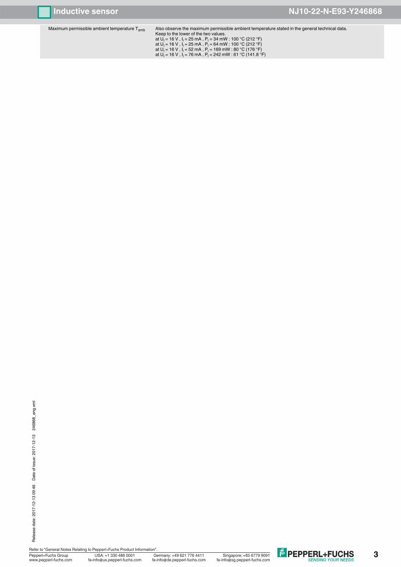
Germany: +49 621 776 4411Pepperl+Fuchs GroupRefer to “General Notes Relating to Pepperl+Fuchs Product Information”.
USA: +1 330 486 0001 Singapore: +65 6779 9091www.pepperl-fuchs.com [email protected] [email protected]@de.pepperl-fuchs.com
Inductive sensor NJ10-22-N-E93-Y246868
3
Rele
ase
date
: 201
7-12
-13
09:4
6D
ate
of is
sue:
201
7-12
-13
2468
68_e
ng.x
ml
Maximum permissible ambient temperature Tamb Also observe the maximum permissible ambient temperature stated in the general technical data.Keep to the lower of the two values. at Ui = 16 V , Ii = 25 mA , Pi = 34 mW : 100 °C (212 °F)at Ui = 16 V , Ii = 25 mA , Pi = 64 mW : 100 °C (212 °F)at Ui = 16 V , Ii = 52 mA , Pi = 169 mW : 80 °C (176 °F)at Ui = 16 V , Ii = 76 mA , Pi = 242 mW : 61 °C (141.8 °F)
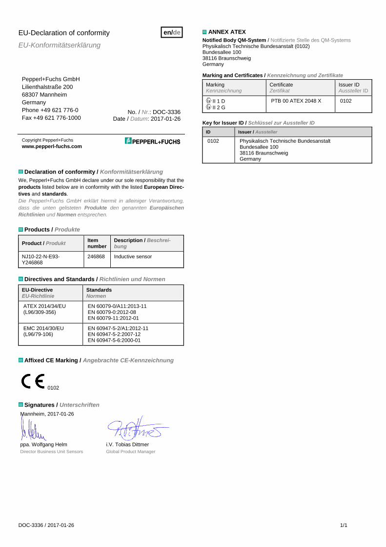
DOC-3336 / 2017-01-26 1/1
EU-Declaration of conformity
EU-Konformitätserklärung
Pepperl+Fuchs GmbH
Lilienthalstraße 200
68307 Mannheim
Germany
Phone +49 621 776-0
Fax +49 621 776-1000 No. / Nr.: DOC-3336
Date / Datum: 2017-01-26
Copyright Pepperl+Fuchs
www.pepperl-fuchs.com
Declaration of conformity / Konformitätserklärung
We, Pepperl+Fuchs GmbH declare under our sole responsibility that the
products listed below are in conformity with the listed European Direc-
tives and standards.
Die Pepperl+Fuchs GmbH erklärt hiermit in alleiniger Verantwortung,
dass die unten gelisteten Produkte den genannten Europäischen
Richtlinien und Normen entsprechen.
Products / Produkte
Product / Produkt Item number
Description / Beschrei-bung
NJ10-22-N-E93-Y246868
246868 Inductive sensor
Directives and Standards / Richtlinien und Normen
EU-Directive EU-Richtlinie
Standards Normen
ATEX 2014/34/EU (L96/309-356)
EN 60079-0/A11:2013-11 EN 60079-0:2012-08 EN 60079-11:2012-01
EMC 2014/30/EU (L96/79-106)
EN 60947-5-2/A1:2012-11 EN 60947-5-2:2007-12 EN 60947-5-6:2000-01
Affixed CE Marking / Angebrachte CE-Kennzeichnung
0102
Signatures / Unterschriften
Mannheim, 2017-01-26
ppa. Wolfgang Helm i.V. Tobias Dittmer
Director Business Unit Sensors Global Product Manager
ANNEX ATEX
Notified Body QM-System / Notifizierte Stelle des QM-Systems Physikalisch Technische Bundesanstalt (0102) Bundesallee 100 38116 Braunschweig Germany
Marking and Certificates / Kennzeichnung und Zertifikate
Marking Kennzeichnung
Certificate Zertifikat
Issuer ID Aussteller ID
II 1 D
II 2 G
PTB 00 ATEX 2048 X 0102
Key for Issuer ID / Schlüssel zur Aussteller ID
ID Issuer / Aussteller
0102 Physikalisch Technische Bundesanstalt Bundesallee 100 38116 Braunschweig Germany
en/de

Man
ual d
e m
onta
gem
e d
e in
stru
ções
/ver
são
11/3
626-
0115
00
pt/c
lass
e de
pro
teçã
o 0:
pub
licam
ente
/15-
07-2
020
47
BTS, Dispositivo de comutação térmica sem contato Anexo
14.6 Detector de proximidade NJ10-22-N-E93-Y246869 Manual de instruções Pepperl+Fuchs Dados técnicos Pepperl+Fuchs Declaração de conformidade Pepperl+Fuchs
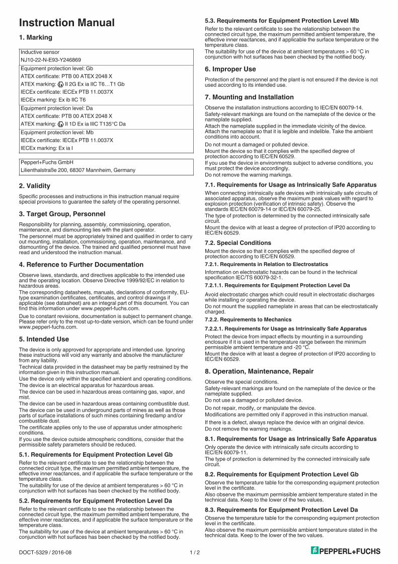
Instruction Manual1. Marking
Inductive sensorNJ10-22-N-E93-Y246869Equipment protection level: GbATEX certificate: PTB 00 ATEX 2048 XATEX marking: II 2G Ex ia IIC T6…T1 GbIECEx certificate: IECEx PTB 11.0037XIECEx marking: Ex ib IIC T6 Equipment protection level: DaATEX certificate: PTB 00 ATEX 2048 XATEX marking: II 1D Ex ia IIIC T135°C DaEquipment protection level: MbIECEx certificate: IECEx PTB 11.0037XIECEx marking: Ex ia I
Pepperl+Fuchs GmbHLilienthalstraße 200, 68307 Mannheim, Germany
2. ValiditySpecific processes and instructions in this instruction manual requirespecial provisions to guarantee the safety of the operating personnel.
3. Target Group, PersonnelResponsibility for planning, assembly, commissioning, operation,maintenance, and dismounting lies with the plant operator.The personnel must be appropriately trained and qualified in order to carryout mounting, installation, commissioning, operation, maintenance, anddismounting of the device. The trained and qualified personnel must haveread and understood the instruction manual.
4. Reference to Further DocumentationObserve laws, standards, and directives applicable to the intended useand the operating location. Observe Directive 1999/92/EC in relation tohazardous areas.The corresponding datasheets, manuals, declarations of conformity, EU-type examination certificates, certificates, and control drawings ifapplicable (see datasheet) are an integral part of this document. You canfind this information under www.pepperl-fuchs.com.Due to constant revisions, documentation is subject to permanent change.Please refer only to the most up-to-date version, which can be found underwww.pepperl-fuchs.com.
5. Intended UseThe device is only approved for appropriate and intended use. Ignoringthese instructions will void any warranty and absolve the manufacturerfrom any liability.Technical data provided in the datasheet may be partly restrained by theinformation given in this instruction manual.Use the device only within the specified ambient and operating conditions.The device is an electrical apparatus for hazardous areas.The device can be used in hazardous areas containing gas, vapor, andmist.The device can be used in hazardous areas containing combustible dust.The device can be used in underground parts of mines as well as thoseparts of surface installations of such mines containing firedamp and/orcombustible dust.The certificate applies only to the use of apparatus under atmosphericconditions.If you use the device outside atmospheric conditions, consider that thepermissible safety parameters should be reduced.
5.1. Requirements for Equipment Protection Level GbRefer to the relevant certificate to see the relationship between theconnected circuit type, the maximum permitted ambient temperature, theeffective inner reactances, and if applicable the surface temperature or thetemperature class.The suitability for use of the device at ambient temperatures > 60 °C inconjunction with hot surfaces has been checked by the notified body.
5.2. Requirements for Equipment Protection Level DaRefer to the relevant certificate to see the relationship between theconnected circuit type, the maximum permitted ambient temperature, theeffective inner reactances, and if applicable the surface temperature or thetemperature class.The suitability for use of the device at ambient temperatures > 60 °C inconjunction with hot surfaces has been checked by the notified body.
5.3. Requirements for Equipment Protection Level MbRefer to the relevant certificate to see the relationship between theconnected circuit type, the maximum permitted ambient temperature, theeffective inner reactances, and if applicable the surface temperature or thetemperature class.The suitability for use of the device at ambient temperatures > 60 °C inconjunction with hot surfaces has been checked by the notified body.
6. Improper UseProtection of the personnel and the plant is not ensured if the device is notused according to its intended use.
7. Mounting and InstallationObserve the installation instructions according to IEC/EN 60079-14.Safety-relevant markings are found on the nameplate of the device or thenameplate supplied.Attach the nameplate supplied in the immediate vicinity of the device.Attach the nameplate so that it is legible and indelible. Take the ambientconditions into account.Do not mount a damaged or polluted device.Mount the device so that it complies with the specified degree ofprotection according to IEC/EN 60529.If you use the device in environments subject to adverse conditions, youmust protect the device accordingly.Do not remove the warning markings.
7.1. Requirements for Usage as Intrinsically Safe ApparatusWhen connecting intrinsically safe devices with intrinsically safe circuits ofassociated apparatus, observe the maximum peak values with regard toexplosion protection (verification of intrinsic safety). Observe thestandards IEC/EN 60079-14 or IEC/EN 60079-25.The type of protection is determined by the connected intrinsically safecircuit.Mount the device with at least a degree of protection of IP20 according toIEC/EN 60529.
7.2. Special ConditionsMount the device so that it complies with the specified degree ofprotection according to IEC/EN 60529.7.2.1. Requirements in Relation to ElectrostaticsInformation on electrostatic hazards can be found in the technicalspecification IEC/TS 60079-32-1.7.2.1.1. Requirements for Equipment Protection Level DaAvoid electrostatic charges which could result in electrostatic dischargeswhile installing or operating the device.Do not mount the supplied nameplate in areas that can be electrostaticallycharged.7.2.2. Requirements to Mechanics7.2.2.1. Requirements for Usage as Intrinsically Safe ApparatusProtect the device from impact effects by mounting in a surroundingenclosure if it is used in the temperature range between the minimumpermissible ambient temperature and -20 °C.Mount the device with at least a degree of protection of IP20 according toIEC/EN 60529.
8. Operation, Maintenance, RepairObserve the special conditions.Safety-relevant markings are found on the nameplate of the device or thenameplate supplied.Do not use a damaged or polluted device.Do not repair, modify, or manipulate the device.Modifications are permitted only if approved in this instruction manual.If there is a defect, always replace the device with an original device.Do not remove the warning markings.
8.1. Requirements for Usage as Intrinsically Safe ApparatusOnly operate the device with intrinsically safe circuits according toIEC/EN 60079-11.The type of protection is determined by the connected intrinsically safecircuit.
8.2. Requirements for Equipment Protection Level GbObserve the temperature table for the corresponding equipment protectionlevel in the certificate.Also observe the maximum permissible ambient temperature stated in thetechnical data. Keep to the lower of the two values.
8.3. Requirements for Equipment Protection Level DaObserve the temperature table for the corresponding equipment protectionlevel in the certificate.Also observe the maximum permissible ambient temperature stated in thetechnical data. Keep to the lower of the two values.
DOCT-5329 / 2016-08 1 / 2

8.4. Requirements for Equipment Protection Level MbObserve the temperature table for the corresponding equipment protectionlevel in the certificate.Also observe the maximum permissible ambient temperature stated in thetechnical data. Keep to the lower of the two values.
9. Delivery, Transport, DisposalCheck the packaging and contents for damage. Check if you have received every item and if the items received are theones you ordered.Keep the original packaging. Always store and transport the device in theoriginal packaging.Store the device in a clean and dry environment. The permitted ambientconditions must be considered, see datasheet.Disposing of device, packaging, and possibly contained batteries must bein compliance with the applicable laws and guidelines of the respectivecountry.
DOCT-5329 / 2016-08 2 / 2
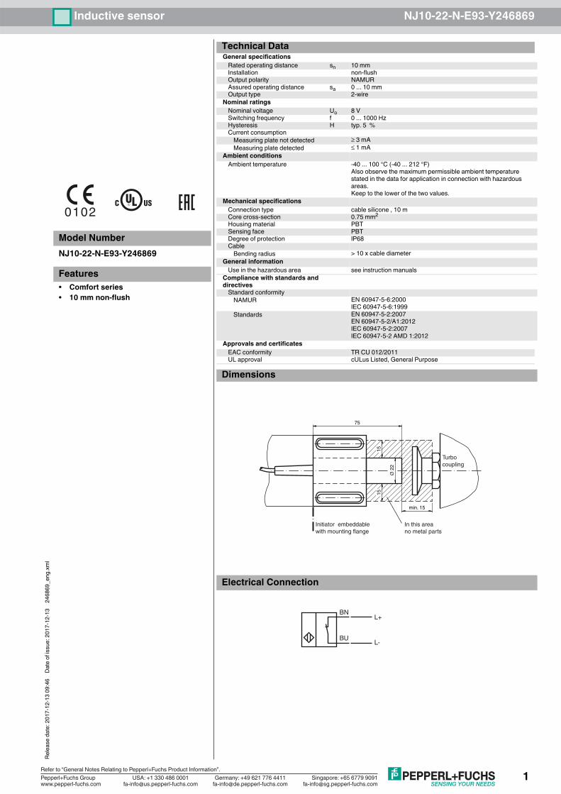
1
Inductive sensor NJ10-22-N-E93-Y246869
Rele
ase
date
: 201
7-12
-13
09:4
6D
ate
of is
sue:
201
7-12
-13
2468
69_e
ng.x
ml
Germany: +49 621 776 4411Pepperl+Fuchs GroupRefer to “General Notes Relating to Pepperl+Fuchs Product Information”.
USA: +1 330 486 0001 Singapore: +65 6779 9091www.pepperl-fuchs.com [email protected] [email protected]@de.pepperl-fuchs.com
0102
Model NumberNJ10-22-N-E93-Y246869
Features Comfort series 10 mm non-flush
Technical DataGeneral specifications
Rated operating distance sn 10 mmInstallation non-flushOutput polarity NAMURAssured operating distance sa 0 ... 10 mmOutput type 2-wire
Nominal ratingsNominal voltage Uo 8 VSwitching frequency f 0 ... 1000 HzHysteresis H typ. 5 %Current consumption
Measuring plate not detected ≥ 3 mAMeasuring plate detected ≤ 1 mA
Ambient conditionsAmbient temperature -40 ... 100 °C (-40 ... 212 °F)
Also observe the maximum permissible ambient temperature stated in the data for application in connection with hazardous areas.Keep to the lower of the two values.
Mechanical specificationsConnection type cable silicone , 10 mCore cross-section 0.75 mm2
Housing material PBTSensing face PBTDegree of protection IP68Cable
Bending radius > 10 x cable diameterGeneral information
Use in the hazardous area see instruction manualsCompliance with standards and directives
Standard conformity NAMUR EN 60947-5-6:2000
IEC 60947-5-6:1999Standards EN 60947-5-2:2007
EN 60947-5-2/A1:2012 IEC 60947-5-2:2007 IEC 60947-5-2 AMD 1:2012
Approvals and certificatesEAC conformity TR CU 012/2011UL approval cULus Listed, General Purpose
Dimensions
Electrical Connection
Initiator embeddablewith mounting flange
In this areano metal parts
Turbocoupling
75
Ø 2
2
min. 15
1515
BN L+
L-BU
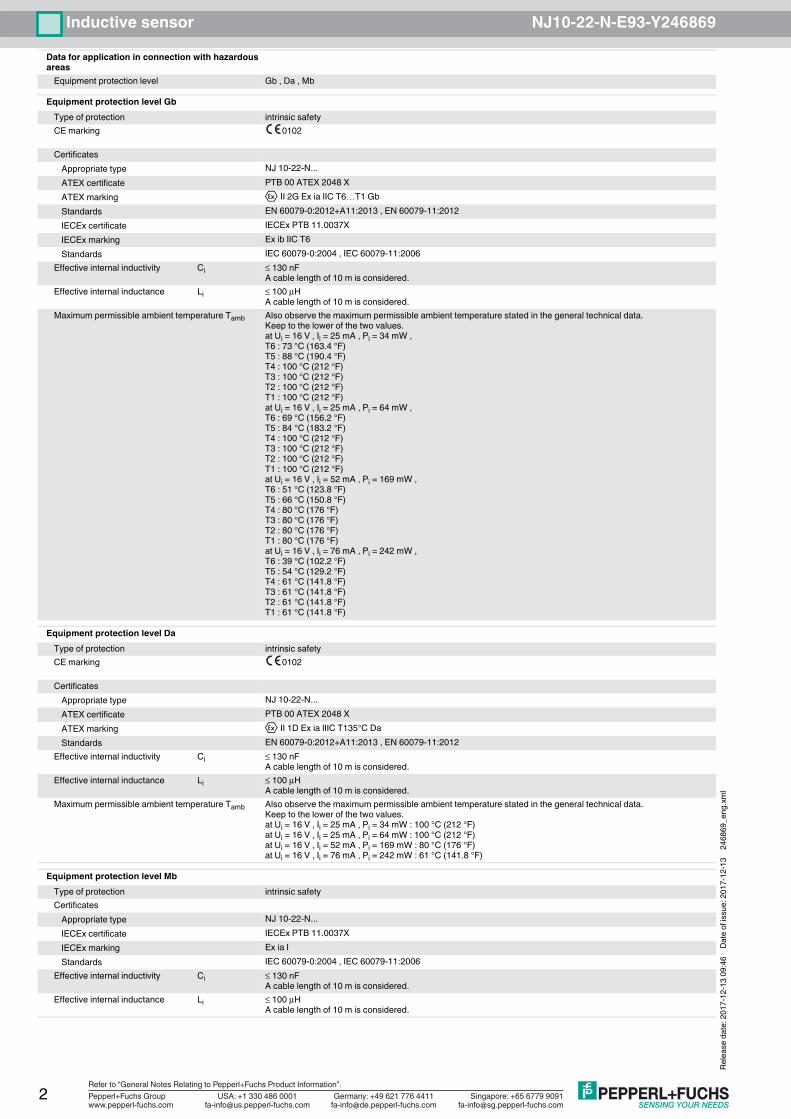
Germany: +49 621 776 4411Pepperl+Fuchs GroupRefer to “General Notes Relating to Pepperl+Fuchs Product Information”.
USA: +1 330 486 0001 Singapore: +65 6779 9091www.pepperl-fuchs.com [email protected] [email protected]@de.pepperl-fuchs.com
Inductive sensor NJ10-22-N-E93-Y246869
2
Rele
ase
date
: 201
7-12
-13
09:4
6D
ate
of is
sue:
201
7-12
-13
2468
69_e
ng.x
ml
Data for application in connection with hazardous areas
Equipment protection level Gb , Da , Mb
Equipment protection level GbType of protection intrinsic safetyCE marking 0102
Certificates Appropriate type NJ 10-22-N...ATEX certificate PTB 00 ATEX 2048 XATEX marking ¬ II 2G Ex ia IIC T6…T1 GbStandards EN 60079-0:2012+A11:2013 , EN 60079-11:2012IECEx certificate IECEx PTB 11.0037XIECEx marking Ex ib IIC T6Standards IEC 60079-0:2004 , IEC 60079-11:2006
Effective internal inductivity Ci ≤ 130 nF A cable length of 10 m is considered.
Effective internal inductance Li ≤ 100 µH A cable length of 10 m is considered.
Maximum permissible ambient temperature Tamb Also observe the maximum permissible ambient temperature stated in the general technical data.Keep to the lower of the two values. at Ui = 16 V , Ii = 25 mA , Pi = 34 mW ,T6 : 73 °C (163.4 °F)T5 : 88 °C (190.4 °F)T4 : 100 °C (212 °F)T3 : 100 °C (212 °F)T2 : 100 °C (212 °F)T1 : 100 °C (212 °F)at Ui = 16 V , Ii = 25 mA , Pi = 64 mW ,T6 : 69 °C (156.2 °F)T5 : 84 °C (183.2 °F)T4 : 100 °C (212 °F)T3 : 100 °C (212 °F)T2 : 100 °C (212 °F)T1 : 100 °C (212 °F)at Ui = 16 V , Ii = 52 mA , Pi = 169 mW ,T6 : 51 °C (123.8 °F)T5 : 66 °C (150.8 °F)T4 : 80 °C (176 °F)T3 : 80 °C (176 °F)T2 : 80 °C (176 °F)T1 : 80 °C (176 °F)at Ui = 16 V , Ii = 76 mA , Pi = 242 mW ,T6 : 39 °C (102.2 °F)T5 : 54 °C (129.2 °F)T4 : 61 °C (141.8 °F)T3 : 61 °C (141.8 °F)T2 : 61 °C (141.8 °F)T1 : 61 °C (141.8 °F)
Equipment protection level DaType of protection intrinsic safetyCE marking 0102
Certificates Appropriate type NJ 10-22-N...ATEX certificate PTB 00 ATEX 2048 XATEX marking ¬ II 1D Ex ia IIIC T135°C DaStandards EN 60079-0:2012+A11:2013 , EN 60079-11:2012
Effective internal inductivity Ci ≤ 130 nF A cable length of 10 m is considered.
Effective internal inductance Li ≤ 100 µH A cable length of 10 m is considered.
Maximum permissible ambient temperature Tamb Also observe the maximum permissible ambient temperature stated in the general technical data.Keep to the lower of the two values. at Ui = 16 V , Ii = 25 mA , Pi = 34 mW : 100 °C (212 °F)at Ui = 16 V , Ii = 25 mA , Pi = 64 mW : 100 °C (212 °F)at Ui = 16 V , Ii = 52 mA , Pi = 169 mW : 80 °C (176 °F)at Ui = 16 V , Ii = 76 mA , Pi = 242 mW : 61 °C (141.8 °F)
Equipment protection level MbType of protection intrinsic safetyCertificates
Appropriate type NJ 10-22-N...IECEx certificate IECEx PTB 11.0037XIECEx marking Ex ia IStandards IEC 60079-0:2004 , IEC 60079-11:2006
Effective internal inductivity Ci ≤ 130 nF A cable length of 10 m is considered.
Effective internal inductance Li ≤ 100 µH A cable length of 10 m is considered.

Germany: +49 621 776 4411Pepperl+Fuchs GroupRefer to “General Notes Relating to Pepperl+Fuchs Product Information”.
USA: +1 330 486 0001 Singapore: +65 6779 9091www.pepperl-fuchs.com [email protected] [email protected]@de.pepperl-fuchs.com
Inductive sensor NJ10-22-N-E93-Y246869
3
Rele
ase
date
: 201
7-12
-13
09:4
6D
ate
of is
sue:
201
7-12
-13
2468
69_e
ng.x
ml
Maximum permissible ambient temperature Tamb Also observe the maximum permissible ambient temperature stated in the general technical data.Keep to the lower of the two values. at Ui = 16 V , Ii = 25 mA , Pi = 34 mW : 100 °C (212 °F)at Ui = 16 V , Ii = 25 mA , Pi = 64 mW : 100 °C (212 °F)at Ui = 16 V , Ii = 52 mA , Pi = 169 mW : 80 °C (176 °F)at Ui = 16 V , Ii = 76 mA , Pi = 242 mW : 61 °C (141.8 °F)

DOC-3335 / 2017-01-26 1/1
EU-Declaration of conformity
EU-Konformitätserklärung
Pepperl+Fuchs GmbH
Lilienthalstraße 200
68307 Mannheim
Germany
Phone +49 621 776-0
Fax +49 621 776-1000 No. / Nr.: DOC-3335
Date / Datum: 2017-01-26
Copyright Pepperl+Fuchs
www.pepperl-fuchs.com
Declaration of conformity / Konformitätserklärung
We, Pepperl+Fuchs GmbH declare under our sole responsibility that the
products listed below are in conformity with the listed European Direc-
tives and standards.
Die Pepperl+Fuchs GmbH erklärt hiermit in alleiniger Verantwortung,
dass die unten gelisteten Produkte den genannten Europäischen
Richtlinien und Normen entsprechen.
Products / Produkte
Product / Produkt Item number
Description / Beschrei-bung
NJ10-22-N-E93-Y246869
246869 Inductive sensor
Directives and Standards / Richtlinien und Normen
EU-Directive EU-Richtlinie
Standards Normen
ATEX 2014/34/EU (L96/309-356)
EN 60079-0/A11:2013-11 EN 60079-0:2012-08 EN 60079-11:2012-01
EMC 2014/30/EU (L96/79-106)
EN 60947-5-2/A1:2012-11 EN 60947-5-2:2007-12 EN 60947-5-6:2000-01
Affixed CE Marking / Angebrachte CE-Kennzeichnung
0102
Signatures / Unterschriften
Mannheim, 2017-01-26
ppa. Wolfgang Helm i.V. Tobias Dittmer
Director Business Unit Sensors Global Product Manager
ANNEX ATEX
Notified Body QM-System / Notifizierte Stelle des QM-Systems Physikalisch Technische Bundesanstalt (0102) Bundesallee 100 38116 Braunschweig Germany
Marking and Certificates / Kennzeichnung und Zertifikate
Marking Kennzeichnung
Certificate Zertifikat
Issuer ID Aussteller ID
II 1 D
II 2 G
PTB 00 ATEX 2048 X 0102
Key for Issuer ID / Schlüssel zur Aussteller ID
ID Issuer / Aussteller
0102 Physikalisch Technische Bundesanstalt Bundesallee 100 38116 Braunschweig Germany
en/de
BTS, Dispositivo de comutação térmica sem contato Anexo
Man
ual d
e m
onta
gem
e d
e in
stru
ções
/ver
são
11/3
626-
0115
00
pt/c
lass
e de
pro
teçã
o 0:
pub
licam
ente
/15-
07-2
020
48
14.7 Dispositivo de leitura KFU8-DW-1.D-Y209869 Dados técnicos Pepperl+Fuchs Declaração de conformidade Pepperl+Fuchs
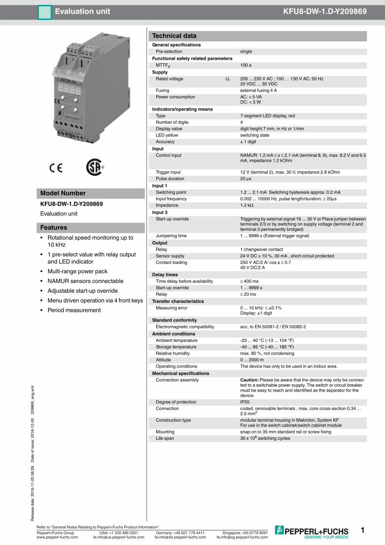
Germany: +49 621 776 4411Pepperl+Fuchs GroupRefer to “General Notes Relating to Pepperl+Fuchs Product Information”.
USA: +1 330 486 0001 Singapore: +65 6779 9091www.pepperl-fuchs.com [email protected] [email protected]@de.pepperl-fuchs.com
1
Rele
ase
date
: 201
6-11
-25
08:2
8D
ate
of is
sue:
201
6-12
-05
2098
69_e
ng.x
ml
Evaluation unit KFU8-DW-1.D-Y209869
Technical dataGeneral specifications
Pre-selection singleFunctional safety related parameters
MTTFd 100 aSupply
Rated voltage Ur 200 ... 230 V AC ; 100 … 130 V AC; 50 Hz 20 VDC ... 30 VDC
Fusing external fusing 4 APower consumption AC: < 5 VA
DC: < 5 WIndicators/operating means
Type 7-segment LED display, redNumber of digits 4Display value digit height 7 mm, in Hz or 1/minLED yellow switching stateAccuracy ± 1 digit
InputControl input NAMUR: 1,2 mA ≤ x ≤ 2,1 mA (terminal 8, 9), max. 8.2 V and 6.5
mA, impedance 1.2 kOhm
Trigger input 12 V (terminal 2), max. 30 V, impedance 2.8 kOhmPulse duration 20 µs
Input 1Switching point 1.2 ... 2.1 mA Switching hysteresis approx. 0.2 mAInput frequency 0.002 ... 10000 Hz, pulse length/duration: ≥ 20µsImpedance 1.2 kΩ
Input 3Start-up override Triggering by external signal 16 ... 30 V or Place jumper between
terminals 2/3 or by switching on supply voltage (terminal 2 and terminal 3 permanently bridged)
Jumpering time 1 ... 9999 s (External trigger signal)Output
Relay 1 changeover contactSensor supply 24 V DC ± 10 %, 30 mA , short-circuit protectedContact loading 250 V AC/2 A/ cos φ ≥ 0.7
40 V DC/2 ADelay times
Time delay before availability ≤ 400 msStart-up override 1 ... 9999 sRelay ≤ 20 ms
Transfer characteristicsMeasuring error 0 ... 10 kHz: ≤ ±0.1%
Display: ±1 digitStandard conformity
Electromagnetic compatibility acc. to EN 50081-2 / EN 50082-2Ambient conditions
Ambient temperature -25 ... 40 °C (-13 ... 104 °F)Storage temperature -40 ... 85 °C (-40 ... 185 °F)Relative humidity max. 80 %, not condensingAltitude 0 ... 2000 mOperating conditions The device has only to be used in an indoor area.
Mechanical specificationsConnection assembly Caution: Please be aware that the device may only be connec-
ted to a switchable power supply. The switch or circuit breaker must be easy to reach and identified as the separator for the device.
Degree of protection IP20Connection coded, removable terminals , max. core cross-section 0.34 ...
2.5 mm2
Construction type modular terminal housing in Makrolon, System KF For use in the switch cabinet/switch cabinet module
Mounting snap-on to 35 mm standard rail or screw fixingLife span 30 x 106 switching cycles
Model NumberKFU8-DW-1.D-Y209869Evaluation unit
Features Rotational speed monitoring up to
10 kHz 1 pre-select value with relay output
and LED indicator Multi-range power pack NAMUR sensors connectable Adjustable start-up override Menu driven operation via 4 front keys Period measurement
Rele
ase
date
: 201
6-11
-25
08:2
8D
ate
of is
sue:
201
6-12
-05
2098
69_e
ng.x
ml
KFU8-DW-1.D-Y209869Evaluation unit
2 Germany: +49 621 776 4411Pepperl+Fuchs GroupRefer to “General Notes Relating to Pepperl+Fuchs Product Information”.
USA: +1 330 486 0001 Singapore: +65 6779 9091www.pepperl-fuchs.com [email protected] [email protected]@de.pepperl-fuchs.com
FunctionThe KFU8-DW-1.D Speed Monitor is a device used to indicate and monitor periodic signals(frequencies and rotational speeds) which occur in almost all areas of automation and processengineering.The input signals are evaluated in accordance with the cycle method. That is, by measuring theduration of a period and then converting it with a very fast micro controller to a frequency orrotational speed.The Speed Monitor can be supplied with 115 V AC, 230 V AC or by a 24 V DC supply andwhen connected to an alternating voltage it provides a 24 V DC source to supply the signalsensor.
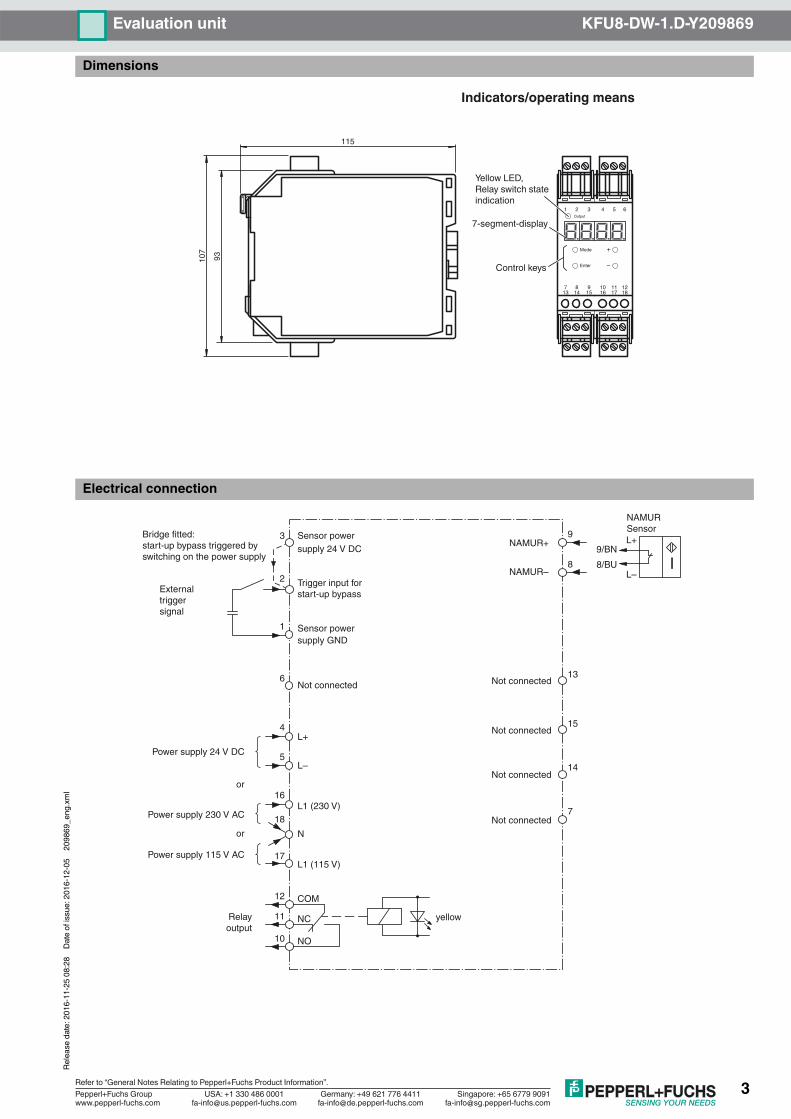
Germany: +49 621 776 4411Pepperl+Fuchs GroupRefer to “General Notes Relating to Pepperl+Fuchs Product Information”.
USA: +1 330 486 0001 Singapore: +65 6779 9091www.pepperl-fuchs.com [email protected] [email protected]@de.pepperl-fuchs.com
3
Rele
ase
date
: 201
6-11
-25
08:2
8D
ate
of is
sue:
201
6-12
-05
2098
69_e
ng.x
ml
Evaluation unit KFU8-DW-1.D-Y209869
Dimensions
Electrical connection
Mode
Output
Enter
+
–
1 2 3 4 5 6
13 14 15 16 17 187 8 9 10 11 12
Control keys
7-segment-display
Yellow LED,Relay switch state indication
Indicators/operating means
107 93
115
NAMUR+
NAMUR–
L+
L–
L+
L–
N
L1 (230 V)
L1 (115 V)
9
8
1
6
3
2
4
5
12
11
10
COM
NC
NO
16
18
17
7
14
15
13
8/BU
9/BN
I
Power supply 115 V AC
Power supply 24 V DC
Sensor powersupply 24 V DC
Power supply 230 V AC
NAMURSensor
Sensor powersupply GND
Not connected Not connected
Not connected
Not connected
Not connected
or
or
yellow
Bridge fitted:start-up bypass triggered byswitching on the power supply
External trigger signal
Trigger input forstart-up bypass
Relayoutput
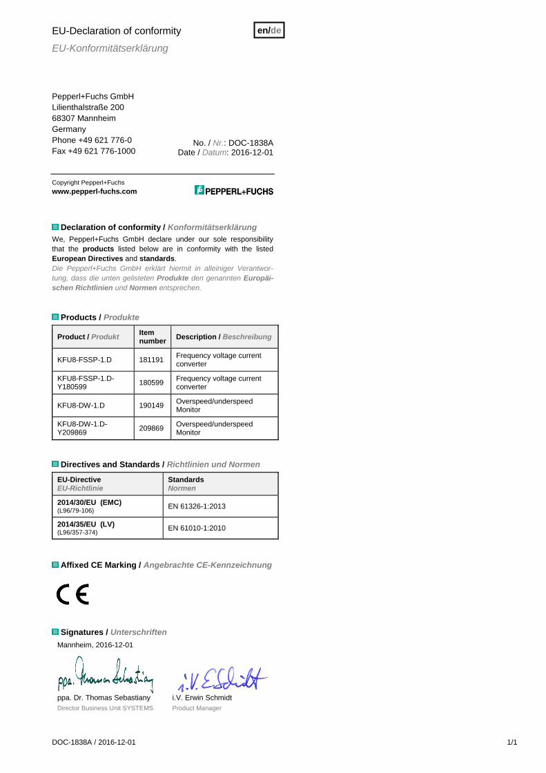
DOC-1838A / 2016-12-01 1/1
EU-Declaration of conformity
EU-Konformitätserklärung
Pepperl+Fuchs GmbH
Lilienthalstraße 200
68307 Mannheim
Germany
Phone +49 621 776-0
Fax +49 621 776-1000 No. / Nr.: DOC-1838A
Date / Datum: 2016-12-01
Copyright Pepperl+Fuchs
www.pepperl-fuchs.com
Declaration of conformity / Konformitätserklärung
We, Pepperl+Fuchs GmbH declare under our sole responsibility
that the products listed below are in conformity with the listed
European Directives and standards.
Die Pepperl+Fuchs GmbH erklärt hiermit in alleiniger Verantwor-
tung, dass die unten gelisteten Produkte den genannten Europäi-
schen Richtlinien und Normen entsprechen.
Products / Produkte
Product / Produkt Item number
Description / Beschreibung
KFU8-FSSP-1.D 181191 Frequency voltage current converter
KFU8-FSSP-1.D-Y180599
180599 Frequency voltage current converter
KFU8-DW-1.D 190149 Overspeed/underspeed Monitor
KFU8-DW-1.D-Y209869
209869 Overspeed/underspeed Monitor
Directives and Standards / Richtlinien und Normen
EU-Directive EU-Richtlinie
Standards Normen
2014/30/EU (EMC) (L96/79-106)
EN 61326-1:2013
2014/35/EU (LV) (L96/357-374)
EN 61010-1:2010
Affixed CE Marking / Angebrachte CE-Kennzeichnung
Signatures / Unterschriften
Mannheim, 2016-12-01
ppa. Dr. Thomas Sebastiany i.V. Erwin Schmidt
Director Business Unit SYSTEMS Product Manager
en/de
Man
ual d
e m
onta
gem
e d
e in
stru
ções
/ver
são
11/3
626-
0115
00
pt/c
lass
e de
pro
teçã
o 0:
pub
licam
ente
/15-
07-2
020
49
BTS, Dispositivo de comutação térmica sem contato Anexo
14.8 Amplificador de isolamento KFD2-SOT2-Ex2 Manual de instruções Pepperl+Fuchs Dados técnicos Pepperl+Fuchs Declaração de conformidade Pepperl+Fuchs
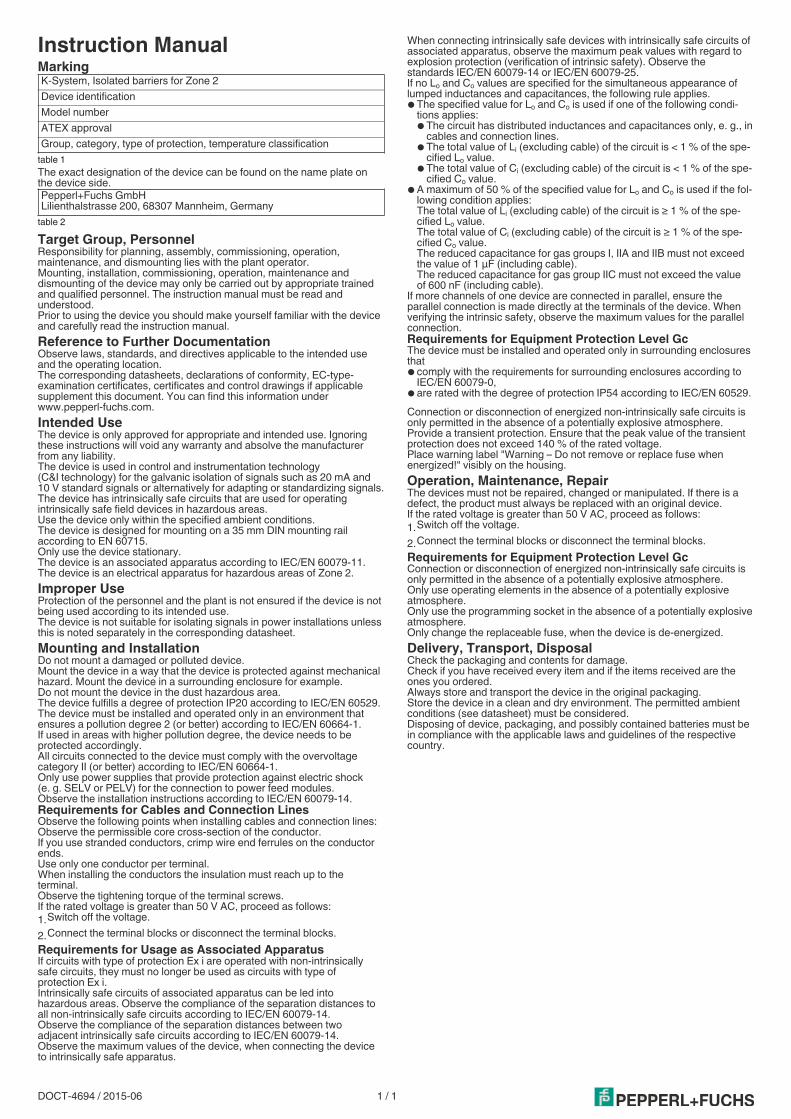
Instruction ManualMarkingK-System, Isolated barriers for Zone 2Device identificationModel numberATEX approvalGroup, category, type of protection, temperature classification
table 1The exact designation of the device can be found on the name plate onthe device side.Pepperl+Fuchs GmbHLilienthalstrasse 200, 68307 Mannheim, Germany
table 2Target Group, PersonnelResponsibility for planning, assembly, commissioning, operation,maintenance, and dismounting lies with the plant operator.Mounting, installation, commissioning, operation, maintenance anddismounting of the device may only be carried out by appropriate trainedand qualified personnel. The instruction manual must be read andunderstood.Prior to using the device you should make yourself familiar with the deviceand carefully read the instruction manual.Reference to Further DocumentationObserve laws, standards, and directives applicable to the intended useand the operating location.The corresponding datasheets, declarations of conformity, EC-type-examination certificates, certificates and control drawings if applicablesupplement this document. You can find this information underwww.pepperl-fuchs.com.Intended UseThe device is only approved for appropriate and intended use. Ignoringthese instructions will void any warranty and absolve the manufacturerfrom any liability.The device is used in control and instrumentation technology(C&I technology) for the galvanic isolation of signals such as 20 mA and10 V standard signals or alternatively for adapting or standardizing signals.The device has intrinsically safe circuits that are used for operatingintrinsically safe field devices in hazardous areas.Use the device only within the specified ambient conditions.The device is designed for mounting on a 35 mm DIN mounting railaccording to EN 60715.Only use the device stationary.The device is an associated apparatus according to IEC/EN 60079-11.The device is an electrical apparatus for hazardous areas of Zone 2.Improper UseProtection of the personnel and the plant is not ensured if the device is notbeing used according to its intended use.The device is not suitable for isolating signals in power installations unlessthis is noted separately in the corresponding datasheet.Mounting and InstallationDo not mount a damaged or polluted device.Mount the device in a way that the device is protected against mechanicalhazard. Mount the device in a surrounding enclosure for example.Do not mount the device in the dust hazardous area.The device fulfills a degree of protection IP20 according to IEC/EN 60529.The device must be installed and operated only in an environment thatensures a pollution degree 2 (or better) according to IEC/EN 60664-1.If used in areas with higher pollution degree, the device needs to beprotected accordingly.All circuits connected to the device must comply with the overvoltagecategory II (or better) according to IEC/EN 60664-1.Only use power supplies that provide protection against electric shock(e. g. SELV or PELV) for the connection to power feed modules.Observe the installation instructions according to IEC/EN 60079-14.Requirements for Cables and Connection LinesObserve the following points when installing cables and connection lines:Observe the permissible core cross-section of the conductor.If you use stranded conductors, crimp wire end ferrules on the conductorends.Use only one conductor per terminal.When installing the conductors the insulation must reach up to theterminal.Observe the tightening torque of the terminal screws.If the rated voltage is greater than 50 V AC, proceed as follows:1.Switch off the voltage.2.Connect the terminal blocks or disconnect the terminal blocks.Requirements for Usage as Associated ApparatusIf circuits with type of protection Ex i are operated with non-intrinsicallysafe circuits, they must no longer be used as circuits with type ofprotection Ex i.Intrinsically safe circuits of associated apparatus can be led intohazardous areas. Observe the compliance of the separation distances toall non-intrinsically safe circuits according to IEC/EN 60079-14.Observe the compliance of the separation distances between twoadjacent intrinsically safe circuits according to IEC/EN 60079-14.Observe the maximum values of the device, when connecting the deviceto intrinsically safe apparatus.
When connecting intrinsically safe devices with intrinsically safe circuits ofassociated apparatus, observe the maximum peak values with regard toexplosion protection (verification of intrinsic safety). Observe thestandards IEC/EN 60079-14 or IEC/EN 60079-25.If no Lo and Co values are specified for the simultaneous appearance oflumped inductances and capacitances, the following rule applies.lThe specified value for Lo and Co is used if one of the following condi-
tions applies:lThe circuit has distributed inductances and capacitances only, e. g., incables and connection lines.lThe total value of Li (excluding cable) of the circuit is < 1 % of the spe-cified Lo value.lThe total value of Ci (excluding cable) of the circuit is < 1 % of the spe-cified Co value.lA maximum of 50 % of the specified value for Lo and Co is used if the fol-
lowing condition applies:The total value of Li (excluding cable) of the circuit is ≥ 1 % of the spe-cified Lo value.The total value of Ci (excluding cable) of the circuit is ≥ 1 % of the spe-cified Co value.The reduced capacitance for gas groups I, IIA and IIB must not exceedthe value of 1 µF (including cable).The reduced capacitance for gas group IIC must not exceed the valueof 600 nF (including cable).
If more channels of one device are connected in parallel, ensure theparallel connection is made directly at the terminals of the device. Whenverifying the intrinsic safety, observe the maximum values for the parallelconnection.Requirements for Equipment Protection Level GcThe device must be installed and operated only in surrounding enclosuresthatl comply with the requirements for surrounding enclosures according to
IEC/EN 60079-0,lare rated with the degree of protection IP54 according to IEC/EN 60529.Connection or disconnection of energized non-intrinsically safe circuits isonly permitted in the absence of a potentially explosive atmosphere.Provide a transient protection. Ensure that the peak value of the transientprotection does not exceed 140 % of the rated voltage.Place warning label "Warning – Do not remove or replace fuse whenenergized!" visibly on the housing.Operation, Maintenance, RepairThe devices must not be repaired, changed or manipulated. If there is adefect, the product must always be replaced with an original device.If the rated voltage is greater than 50 V AC, proceed as follows:1.Switch off the voltage.2.Connect the terminal blocks or disconnect the terminal blocks.Requirements for Equipment Protection Level GcConnection or disconnection of energized non-intrinsically safe circuits isonly permitted in the absence of a potentially explosive atmosphere.Only use operating elements in the absence of a potentially explosiveatmosphere.Only use the programming socket in the absence of a potentially explosiveatmosphere.Only change the replaceable fuse, when the device is de-energized.Delivery, Transport, DisposalCheck the packaging and contents for damage. Check if you have received every item and if the items received are theones you ordered.Always store and transport the device in the original packaging.Store the device in a clean and dry environment. The permitted ambientconditions (see datasheet) must be considered.Disposing of device, packaging, and possibly contained batteries must bein compliance with the applicable laws and guidelines of the respectivecountry.
DOCT-4694 / 2015-06
en
1 / 1
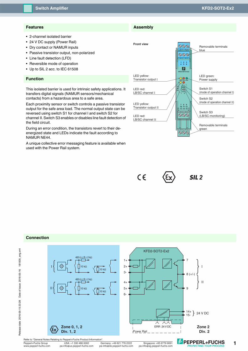
Rele
ase
date
201
6-05
-15
23:2
8D
ate
of is
sue
201
6-05
-16
1810
05_e
ng.x
ml
KFD2-SOT2-Ex2
1Refer to "General Notes Relating to Pepperl+Fuchs Product Information".Pepperl+Fuchs Group USA: +1 330 486 0002 Singapore: +65 6779 9091Germany: +49 621 776 2222www.pepperl-fuchs.com [email protected] [email protected] [email protected]
Switch Amplifier
Zone 2Div. 2
Zone 0, 1, 2Div. 1, 2
KFD2-SOT2-Ex2
24 V DC14+15-
Power Rail
24 V DCERR
7
8 (+/-)
9
I
II
2+
3-
1+
I
II 5+
6-
4+
10 kΩ
400 Ω ≤ R ≤ 2 kΩ
10 kΩ10 kΩ
400 Ω ≤ R ≤ 2 kΩ
10 kΩ
Connection
Assembly
• 2-channel isolated barrier• 24 V DC supply (Power Rail)• Dry contact or NAMUR inputs• Passive transistor output, non-polarized• Line fault detection (LFD)• Reversible mode of operation• Up to SIL 2 acc. to IEC 61508
Function
This isolated barrier is used for intrinsic safety applications. It transfers digital signals (NAMUR sensors/mechanical contacts) from a hazardous area to a safe area.Each proximity sensor or switch controls a passive transistor output for the safe area load. The normal output state can be reversed using switch S1 for channel I and switch S2 for channel II. Switch S3 enables or disables line fault detection of the field circuit.During an error condition, the transistors revert to their de-energized state and LEDs indicate the fault according to NAMUR NE44.A unique collective error messaging feature is available when used with the Power Rail system.
2
Features
1 34 6
25
13 15129
107
14118
KFD2-SOT2-Ex2
1
2OUT CHK PWR
S2S1
S3
III
Front view
LED yellow:Transistor output I
LED yellow:Transistor output II
LED green:Power supply
Switch S1(mode of operation channel I)
Switch S2(mode of operation channel II)
Removable terminalsgreen
Removable terminalsblue
LED red:LB/SC channel I
LED red:LB/SC channel II
Switch S3(LB/SC-monitoring)
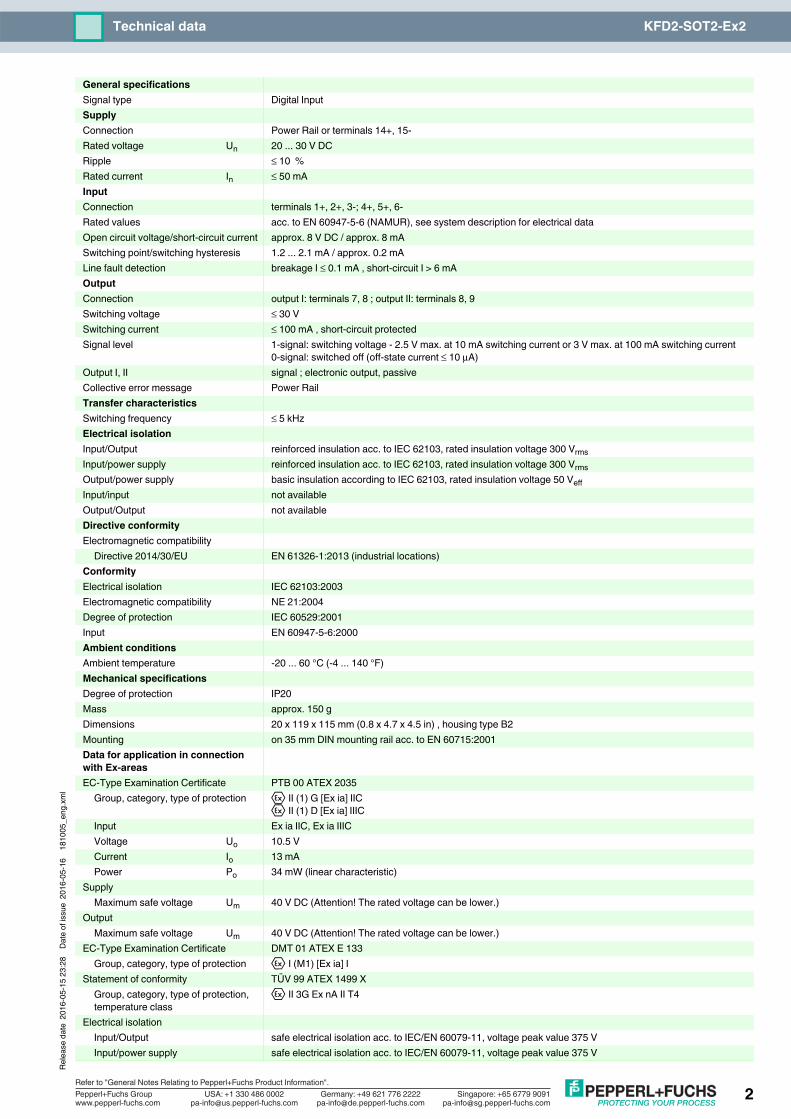
Rele
ase
date
201
6-05
-15
23:2
8D
ate
of is
sue
201
6-05
-16
1810
05_e
ng.x
ml
Technical data KFD2-SOT2-Ex2
2Refer to "General Notes Relating to Pepperl+Fuchs Product Information".Pepperl+Fuchs Group USA: +1 330 486 0002 Singapore: +65 6779 9091Germany: +49 621 776 2222www.pepperl-fuchs.com [email protected] [email protected] [email protected]
General specificationsSignal type Digital InputSupplyConnection Power Rail or terminals 14+, 15-Rated voltage Un 20 ... 30 V DCRipple ≤ 10 %Rated current In ≤ 50 mAInputConnection terminals 1+, 2+, 3-; 4+, 5+, 6-Rated values acc. to EN 60947-5-6 (NAMUR), see system description for electrical dataOpen circuit voltage/short-circuit current approx. 8 V DC / approx. 8 mASwitching point/switching hysteresis 1.2 ... 2.1 mA / approx. 0.2 mALine fault detection breakage I ≤ 0.1 mA , short-circuit I > 6 mAOutputConnection output I: terminals 7, 8 ; output II: terminals 8, 9Switching voltage ≤ 30 VSwitching current ≤ 100 mA , short-circuit protectedSignal level 1-signal: switching voltage - 2.5 V max. at 10 mA switching current or 3 V max. at 100 mA switching current
0-signal: switched off (off-state current ≤ 10 µA)Output I, II signal ; electronic output, passiveCollective error message Power RailTransfer characteristicsSwitching frequency ≤ 5 kHzElectrical isolationInput/Output reinforced insulation acc. to IEC 62103, rated insulation voltage 300 VrmsInput/power supply reinforced insulation acc. to IEC 62103, rated insulation voltage 300 VrmsOutput/power supply basic insulation according to IEC 62103, rated insulation voltage 50 VeffInput/input not availableOutput/Output not availableDirective conformityElectromagnetic compatibility
Directive 2014/30/EU EN 61326-1:2013 (industrial locations)ConformityElectrical isolation IEC 62103:2003Electromagnetic compatibility NE 21:2004Degree of protection IEC 60529:2001Input EN 60947-5-6:2000Ambient conditionsAmbient temperature -20 ... 60 °C (-4 ... 140 °F)Mechanical specificationsDegree of protection IP20Mass approx. 150 gDimensions 20 x 119 x 115 mm (0.8 x 4.7 x 4.5 in) , housing type B2Mounting on 35 mm DIN mounting rail acc. to EN 60715:2001Data for application in connection with Ex-areasEC-Type Examination Certificate PTB 00 ATEX 2035
Group, category, type of protection ¬ II (1) G [Ex ia] IIC ¬ II (1) D [Ex ia] IIIC
Input Ex ia IIC, Ex ia IIICVoltage Uo 10.5 VCurrent Io 13 mAPower Po 34 mW (linear characteristic)
Supply Maximum safe voltage Um 40 V DC (Attention! The rated voltage can be lower.)
Output Maximum safe voltage Um 40 V DC (Attention! The rated voltage can be lower.)
EC-Type Examination Certificate DMT 01 ATEX E 133Group, category, type of protection ¬ I (M1) [Ex ia] I
Statement of conformity TÜV 99 ATEX 1499 XGroup, category, type of protection, temperature class
¬ II 3G Ex nA II T4
Electrical isolation Input/Output safe electrical isolation acc. to IEC/EN 60079-11, voltage peak value 375 VInput/power supply safe electrical isolation acc. to IEC/EN 60079-11, voltage peak value 375 V
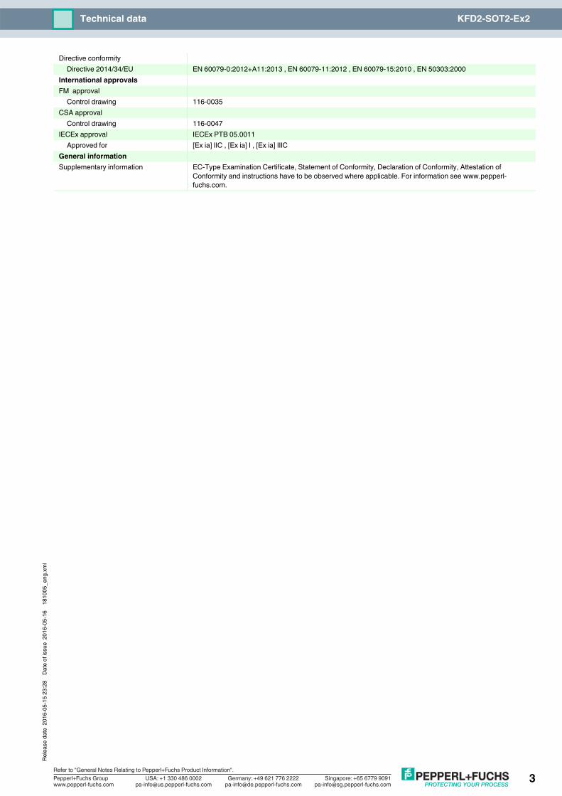
Rele
ase
date
201
6-05
-15
23:2
8D
ate
of is
sue
201
6-05
-16
1810
05_e
ng.x
ml
Technical data KFD2-SOT2-Ex2
3Refer to "General Notes Relating to Pepperl+Fuchs Product Information".Pepperl+Fuchs Group USA: +1 330 486 0002 Singapore: +65 6779 9091Germany: +49 621 776 2222www.pepperl-fuchs.com [email protected] [email protected] [email protected]
Directive conformity Directive 2014/34/EU EN 60079-0:2012+A11:2013 , EN 60079-11:2012 , EN 60079-15:2010 , EN 50303:2000
International approvalsFM approval
Control drawing 116-0035CSA approval
Control drawing 116-0047IECEx approval IECEx PTB 05.0011
Approved for [Ex ia] IIC , [Ex ia] I , [Ex ia] IIICGeneral informationSupplementary information EC-Type Examination Certificate, Statement of Conformity, Declaration of Conformity, Attestation of
Conformity and instructions have to be observed where applicable. For information see www.pepperl-fuchs.com.
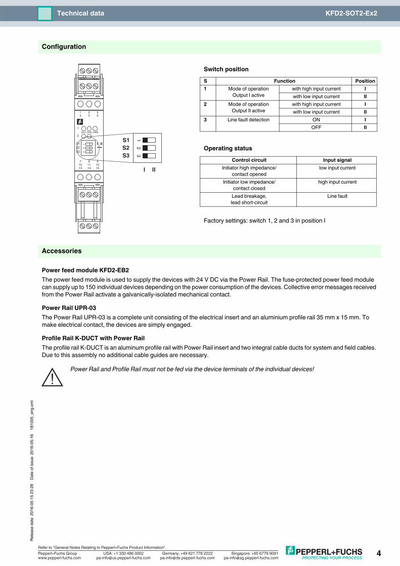
Rele
ase
date
201
6-05
-15
23:2
8D
ate
of is
sue
201
6-05
-16
1810
05_e
ng.x
ml
Technical data KFD2-SOT2-Ex2
4Refer to "General Notes Relating to Pepperl+Fuchs Product Information".Pepperl+Fuchs Group USA: +1 330 486 0002 Singapore: +65 6779 9091Germany: +49 621 776 2222www.pepperl-fuchs.com [email protected] [email protected] [email protected]
Power feed module KFD2-EB2The power feed module is used to supply the devices with 24 V DC via the Power Rail. The fuse-protected power feed module can supply up to 150 individual devices depending on the power consumption of the devices. Collective error messages received from the Power Rail activate a galvanically-isolated mechanical contact.
Power Rail UPR-03The Power Rail UPR-03 is a complete unit consisting of the electrical insert and an aluminium profile rail 35 mm x 15 mm. To make electrical contact, the devices are simply engaged.
Profile Rail K-DUCT with Power RailThe profile rail K-DUCT is an aluminum profile rail with Power Rail insert and two integral cable ducts for system and field cables. Due to this assembly no additional cable guides are necessary.
Power Rail and Profile Rail must not be fed via the device terminals of the individual devices!
Configuration
7 8 910 11 12
1 2 34 5 6
13 14 15
1
2PWRCHKOUT
S1S2S3
12
3
12
3
S1
S3
II
S2
I
Switch position
Operating status
Factory settings: switch 1, 2 and 3 in position I
S Function Position1 Mode of operation
Output I activewith high input current Iwith low input current II
2 Mode of operationOutput II active
with high input current Iwith low input current II
3 Line fault detection ON IOFF II
Control circuit Input signalInitiator high impedance/
contact openedlow input current
Initiator low impedance/contact closed
high input current
Lead breakage,lead short-circuit
Line fault
Accessories
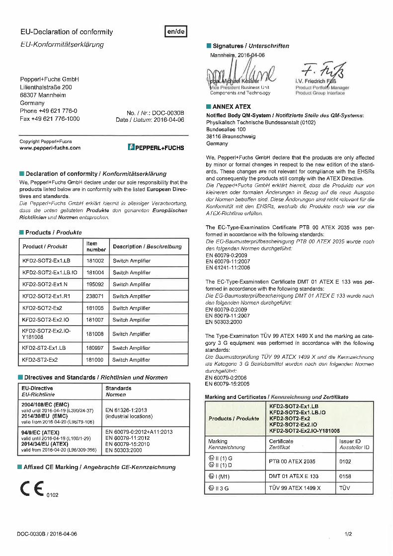
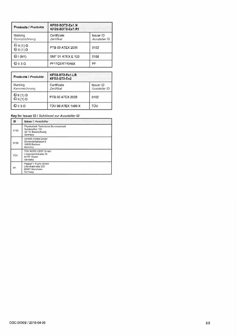
BTS, Dispositivo de comutação térmica sem contato Anexo
Man
ual d
e m
onta
gem
e d
e in
stru
ções
/ver
são
11/3
626-
0115
00
pt/c
lass
e de
pro
teçã
o 0:
pub
licam
ente
/15-
07-2
020
50
14.9 Amplificador de isolamento KFA6-SOT2-Ex2 Manual de instruções Pepperl+Fuchs Dados técnicos Pepperl+Fuchs Declaração de conformidade Pepperl+Fuchs
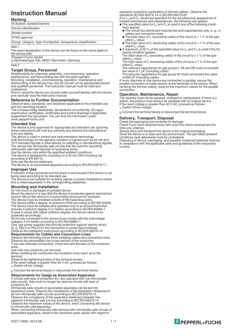
Instruction ManualMarkingK-System, Isolated barriersDevice identificationModel numberATEX approvalGroup, category, type of protection, temperature classification
table 1The exact designation of the device can be found on the name plate onthe device side.Pepperl+Fuchs GmbHLilienthalstrasse 200, 68307 Mannheim, Germany
table 2Target Group, PersonnelResponsibility for planning, assembly, commissioning, operation,maintenance, and dismounting lies with the plant operator.Mounting, installation, commissioning, operation, maintenance anddismounting of the device may only be carried out by appropriate trainedand qualified personnel. The instruction manual must be read andunderstood.Prior to using the device you should make yourself familiar with the deviceand carefully read the instruction manual.Reference to Further DocumentationObserve laws, standards, and directives applicable to the intended useand the operating location.The corresponding datasheets, declarations of conformity, EC-type-examination certificates, certificates and control drawings if applicablesupplement this document. You can find this information underwww.pepperl-fuchs.com.Intended UseThe device is only approved for appropriate and intended use. Ignoringthese instructions will void any warranty and absolve the manufacturerfrom any liability.The device is used in control and instrumentation technology(C&I technology) for the galvanic isolation of signals such as 20 mA and10 V standard signals or alternatively for adapting or standardizing signals.The device has intrinsically safe circuits that are used for operatingintrinsically safe field devices in hazardous areas.Use the device only within the specified ambient conditions.The device is designed for mounting on a 35 mm DIN mounting railaccording to EN 60715.Only use the device stationary.The device is an associated apparatus according to IEC/EN 60079-11.Improper UseProtection of the personnel and the plant is not ensured if the device is notbeing used according to its intended use.The device is not suitable for isolating signals in power installations unlessthis is noted separately in the corresponding datasheet.Mounting and InstallationDo not mount a damaged or polluted device.Mount the device in a way that the device is protected against mechanicalhazard. Mount the device in a surrounding enclosure for example.The device must be installed outside of the hazardous area.The device fulfills a degree of protection IP20 according to IEC/EN 60529.The device must be installed and operated only in an environment thatensures a pollution degree 2 (or better) according to IEC/EN 60664-1.If used in areas with higher pollution degree, the device needs to beprotected accordingly.All circuits connected to the device must comply with the overvoltagecategory II (or better) according to IEC/EN 60664-1.Only use power supplies that provide protection against electric shock(e. g. SELV or PELV) for the connection to power feed modules.Observe the installation instructions according to IEC/EN 60079-14.Requirements for Cables and Connection LinesObserve the following points when installing cables and connection lines:Observe the permissible core cross-section of the conductor.If you use stranded conductors, crimp wire end ferrules on the conductorends.Use only one conductor per terminal.When installing the conductors the insulation must reach up to theterminal.Observe the tightening torque of the terminal screws.If the rated voltage is greater than 50 V AC, proceed as follows:1.Switch off the voltage.2.Connect the terminal blocks or disconnect the terminal blocks.Requirements for Usage as Associated ApparatusIf circuits with type of protection Ex i are operated with non-intrinsicallysafe circuits, they must no longer be used as circuits with type ofprotection Ex i.Intrinsically safe circuits of associated apparatus can be led intohazardous areas. Observe the compliance of the separation distances toall non-intrinsically safe circuits according to IEC/EN 60079-14.Observe the compliance of the separation distances between twoadjacent intrinsically safe circuits according to IEC/EN 60079-14.Observe the maximum values of the device, when connecting the deviceto intrinsically safe apparatus.When connecting intrinsically safe devices with intrinsically safe circuits ofassociated apparatus, observe the maximum peak values with regard to
explosion protection (verification of intrinsic safety). Observe thestandards IEC/EN 60079-14 or IEC/EN 60079-25.If no Lo and Co values are specified for the simultaneous appearance oflumped inductances and capacitances, the following rule applies.lThe specified value for Lo and Co is used if one of the following condi-
tions applies:lThe circuit has distributed inductances and capacitances only, e. g., incables and connection lines.lThe total value of Li (excluding cable) of the circuit is < 1 % of the spe-cified Lo value.lThe total value of Ci (excluding cable) of the circuit is < 1 % of the spe-cified Co value.lA maximum of 50 % of the specified value for Lo and Co is used if the fol-
lowing condition applies:The total value of Li (excluding cable) of the circuit is ≥ 1 % of the spe-cified Lo value.The total value of Ci (excluding cable) of the circuit is ≥ 1 % of the spe-cified Co value.The reduced capacitance for gas groups I, IIA and IIB must not exceedthe value of 1 µF (including cable).The reduced capacitance for gas group IIC must not exceed the valueof 600 nF (including cable).
If more channels of one device are connected in parallel, ensure theparallel connection is made directly at the terminals of the device. Whenverifying the intrinsic safety, observe the maximum values for the parallelconnection.Operation, Maintenance, RepairThe devices must not be repaired, changed or manipulated. If there is adefect, the product must always be replaced with an original device.If the rated voltage is greater than 50 V AC, proceed as follows:1.Switch off the voltage.2.Connect the terminal blocks or disconnect the terminal blocks.Delivery, Transport, DisposalCheck the packaging and contents for damage. Check if you have received every item and if the items received are theones you ordered.Always store and transport the device in the original packaging.Store the device in a clean and dry environment. The permitted ambientconditions (see datasheet) must be considered.Disposing of device, packaging, and possibly contained batteries must bein compliance with the applicable laws and guidelines of the respectivecountry.
DOCT-4693 / 2015-06
en
1 / 1
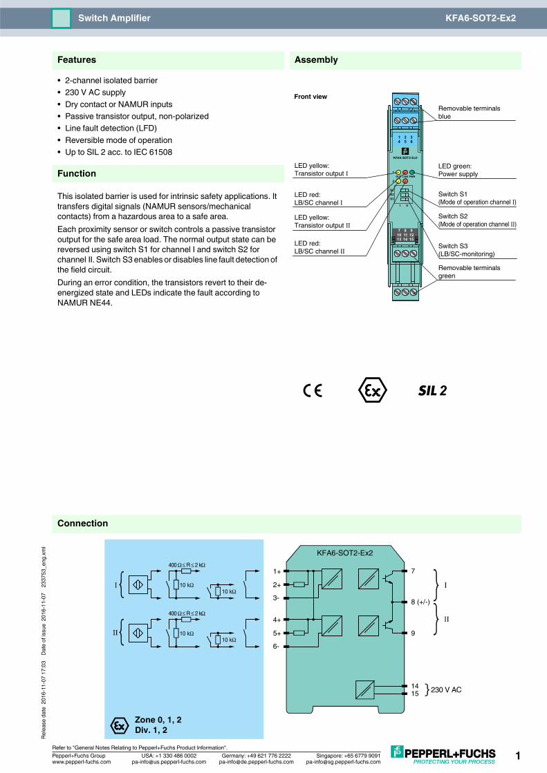
KFA6-SOT2-Ex2
1
Switch Amplifier
Connection
Assembly 2-channel isolated barrier 230 V AC supply Dry contact or NAMUR inputs Passive transistor output, non-polarized Line fault detection (LFD) Reversible mode of operation Up to SIL 2 acc. to IEC 61508
Function
This isolated barrier is used for intrinsic safety applications. It transfers digital signals (NAMUR sensors/mechanical contacts) from a hazardous area to a safe area.Each proximity sensor or switch controls a passive transistor output for the safe area load. The normal output state can be reversed using switch S1 for channel I and switch S2 for channel II. Switch S3 enables or disables line fault detection of the field circuit.During an error condition, the transistors revert to their de-energized state and LEDs indicate the fault according to NAMUR NE44.
Features
1 34 6
25
13 15129
107
14118
KFA6-SOT2-Ex2
1
2OUT CHK PWR
S2S1
S3
III
I
I
II
II
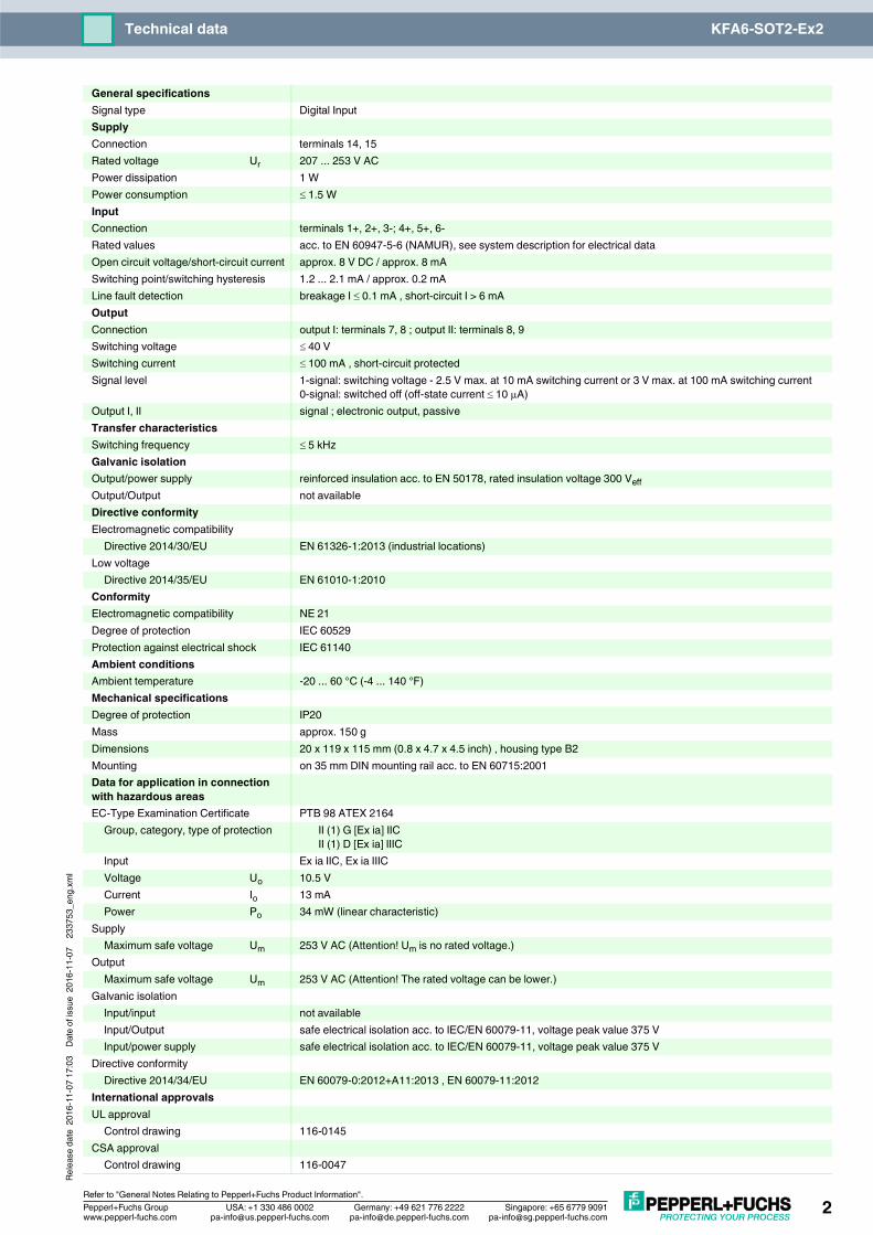
Technical data KFA6-SOT2-Ex2
2
General specificationsSignal type Digital InputSupplyConnection terminals 14, 15Rated voltage Ur 207 ... 253 V ACPower dissipation 1 WPower consumption 1.5 WInputConnection terminals 1+, 2+, 3-; 4+, 5+, 6-Rated values acc. to EN 60947-5-6 (NAMUR), see system description for electrical dataOpen circuit voltage/short-circuit current approx. 8 V DC / approx. 8 mASwitching point/switching hysteresis 1.2 ... 2.1 mA / approx. 0.2 mALine fault detection breakage I 0.1 mA , short-circuit I > 6 mAOutputConnection output I: terminals 7, 8 ; output II: terminals 8, 9Switching voltage 40 VSwitching current 100 mA , short-circuit protectedSignal level 1-signal: switching voltage - 2.5 V max. at 10 mA switching current or 3 V max. at 100 mA switching current
0-signal: switched off (off-state current 10 A)Output I, II signal ; electronic output, passiveTransfer characteristicsSwitching frequency 5 kHzGalvanic isolationOutput/power supply reinforced insulation acc. to EN 50178, rated insulation voltage 300 Veff Output/Output not availableDirective conformityElectromagnetic compatibility
Directive 2014/30/EU EN 61326-1:2013 (industrial locations)Low voltage
Directive 2014/35/EU EN 61010-1:2010ConformityElectromagnetic compatibility NE 21Degree of protection IEC 60529Protection against electrical shock IEC 61140Ambient conditionsAmbient temperature -20 ... 60 °C (-4 ... 140 °F)Mechanical specificationsDegree of protection IP20Mass approx. 150 gDimensions 20 x 119 x 115 mm (0.8 x 4.7 x 4.5 inch) , housing type B2Mounting on 35 mm DIN mounting rail acc. to EN 60715:2001Data for application in connection with hazardous areasEC-Type Examination Certificate PTB 98 ATEX 2164
Group, category, type of protection II (1) G [Ex ia] IIC II (1) D [Ex ia] IIIC
Input Ex ia IIC, Ex ia IIICVoltage Uo 10.5 VCurrent Io 13 mAPower Po 34 mW (linear characteristic)
Supply Maximum safe voltage Um 253 V AC (Attention! Um is no rated voltage.)
Output Maximum safe voltage Um 253 V AC (Attention! The rated voltage can be lower.)
Galvanic isolation Input/input not availableInput/Output safe electrical isolation acc. to IEC/EN 60079-11, voltage peak value 375 VInput/power supply safe electrical isolation acc. to IEC/EN 60079-11, voltage peak value 375 V
Directive conformity Directive 2014/34/EU EN 60079-0:2012+A11:2013 , EN 60079-11:2012
International approvalsUL approval
Control drawing 116-0145CSA approval
Control drawing 116-0047
Technical data KFA6-SOT2-Ex2
3
General informationSupplementary information EC-Type Examination Certificate, Statement of Conformity, Declaration of Conformity, Attestation of
Conformity and instructions have to be observed where applicable. For information see www.pepperl-fuchs.com.
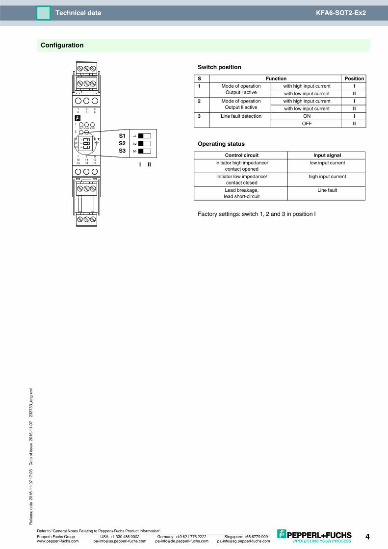
Technical data KFA6-SOT2-Ex2
4
Configuration
Switch position
Operating status
Factory settings: switch 1, 2 and 3 in position I
S Function Position1 Mode of operation
Output I activewith high input current Iwith low input current II
2 Mode of operationOutput II active
with high input current Iwith low input current II
3 Line fault detection ON IOFF II
Control circuit Input signalInitiator high impedance/
contact openedlow input current
Initiator low impedance/contact closed
high input current
Lead breakage,lead short-circuit
Line fault
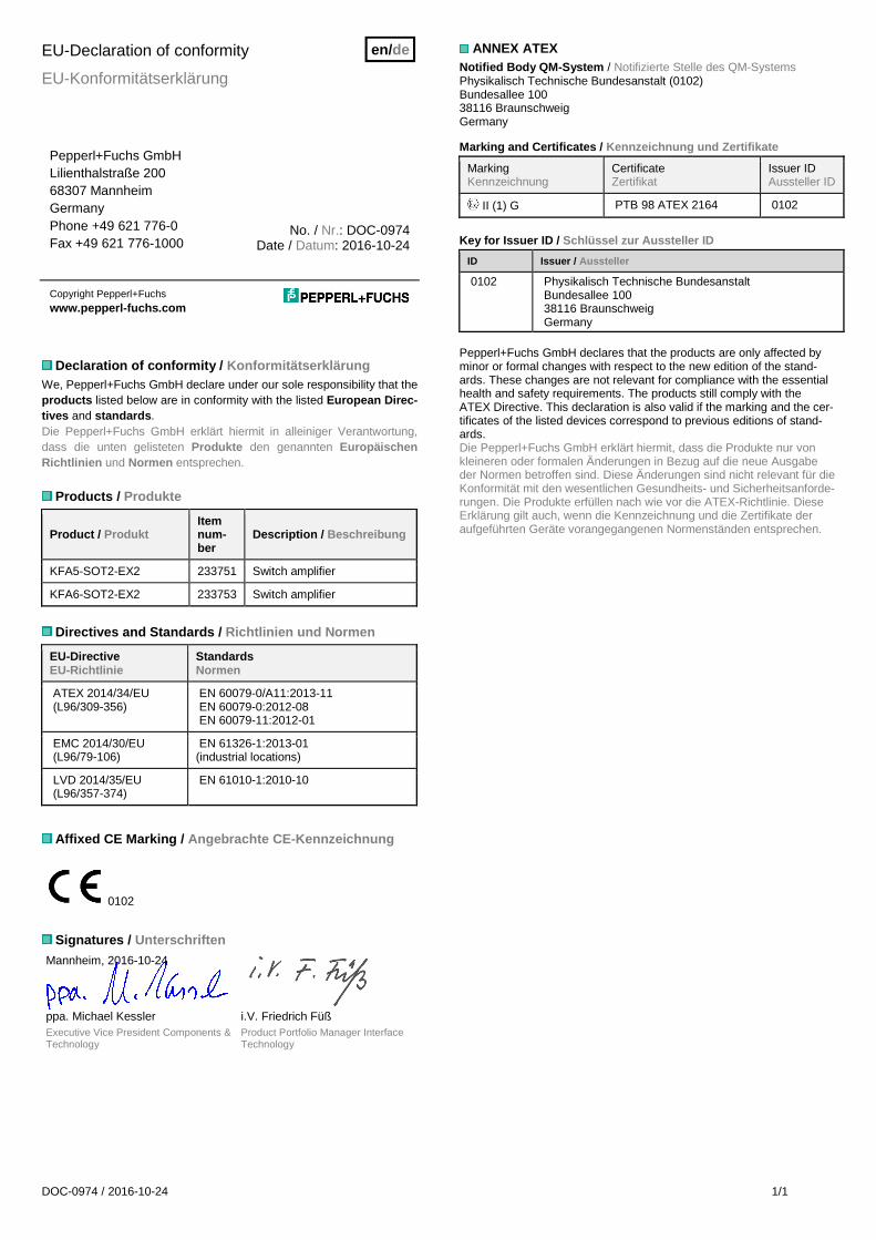
DOC-0974 / 2016-10-24 1/1
EU-Declaration of conformity
EU-Konformitätserklärung
Pepperl+Fuchs GmbH Lilienthalstraße 200 68307 Mannheim Germany Phone +49 621 776-0 Fax +49 621 776-1000
No. / Nr.: DOC-0974 Date / Datum: 2016-10-24
Copyright Pepperl+Fuchs www.pepperl-fuchs.com
Declaration of conformity / Konformitätserklärung We, Pepperl+Fuchs GmbH declare under our sole responsibility that the products listed below are in conformity with the listed European Direc-tives and standards. Die Pepperl+Fuchs GmbH erklärt hiermit in alleiniger Verantwortung, dass die unten gelisteten Produkte den genannten Europäischen Richtlinien und Normen entsprechen.
Products / Produkte
Product / Produkt Item num-ber
Description / Beschreibung
KFA5-SOT2-EX2 233751 Switch amplifier
KFA6-SOT2-EX2 233753 Switch amplifier
Directives and Standards / Richtlinien und Normen
EU-Directive EU-Richtlinie
Standards Normen
ATEX 2014/34/EU (L96/309-356)
EN 60079-0/A11:2013-11 EN 60079-0:2012-08 EN 60079-11:2012-01
EMC 2014/30/EU (L96/79-106)
EN 61326-1:2013-01 (industrial locations)
LVD 2014/35/EU (L96/357-374)
EN 61010-1:2010-10
Affixed CE Marking / Angebrachte CE-Kennzeichnung
0102
Signatures / Unterschriften
Mannheim, 2016-10-24
ppa. Michael Kessler i.V. Friedrich Füß Executive Vice President Components & Technology
Product Portfolio Manager Interface Technology
ANNEX ATEX Notified Body QM-System / Notifizierte Stelle des QM-Systems Physikalisch Technische Bundesanstalt (0102) Bundesallee 100 38116 Braunschweig Germany
Marking and Certificates / Kennzeichnung und Zertifikate
Marking Kennzeichnung
Certificate Zertifikat
Issuer ID Aussteller ID
II (1) G PTB 98 ATEX 2164 0102
Key for Issuer ID / Schlüssel zur Aussteller ID
ID Issuer / Aussteller
0102 Physikalisch Technische Bundesanstalt Bundesallee 100 38116 Braunschweig Germany
Pepperl+Fuchs GmbH declares that the products are only affected by minor or formal changes with respect to the new edition of the stand-ards. These changes are not relevant for compliance with the essential health and safety requirements. The products still comply with the ATEX Directive. This declaration is also valid if the marking and the cer-tificates of the listed devices correspond to previous editions of stand-ards. Die Pepperl+Fuchs GmbH erklärt hiermit, dass die Produkte nur von kleineren oder formalen Änderungen in Bezug auf die neue Ausgabe der Normen betroffen sind. Diese Änderungen sind nicht relevant für die Konformität mit den wesentlichen Gesundheits- und Sicherheitsanforde-rungen. Die Produkte erfüllen nach wie vor die ATEX-Richtlinie. Diese Erklärung gilt auch, wenn die Kennzeichnung und die Zertifikate der aufgeführten Geräte vorangegangenen Normenständen entsprechen.
en/de

Voith Group St. Pöltener Str. 43 89522 Heidenheim, ALEMANHA Telefone: + 49 7951 32 1666 E-mail: [email protected] Internet: www.voith.com/fluid-couplings