Embed Size (px)
Citation preview
Manual de Instruções para Mufla/Waterlock NLP Vetus
Em caso dúvidas na instalação após a leitura do manual, favor entrar em
contato com nosso departamento técnico através do telefone ou email:
• (11) 3477-5655�
• email: [email protected]
Horários de atendimento:
Segunda-feira à quinta-feira: 8h – 18h
Sexta-feira: 8h – 17h
Rua Anhaia 982, Bom Retiro – SP
www.marineoffice.com.br
Installatie instructiesInstallation instructionsInstallationsvorschriften Instructions d’installationInstrucciones de instalaciónIstruzioni per l’installazione
NEDERLANDS 2ENGLISH 4DEUTSCH 6FRANÇAIS 8ESPAÑOL 10ITALIANO 12
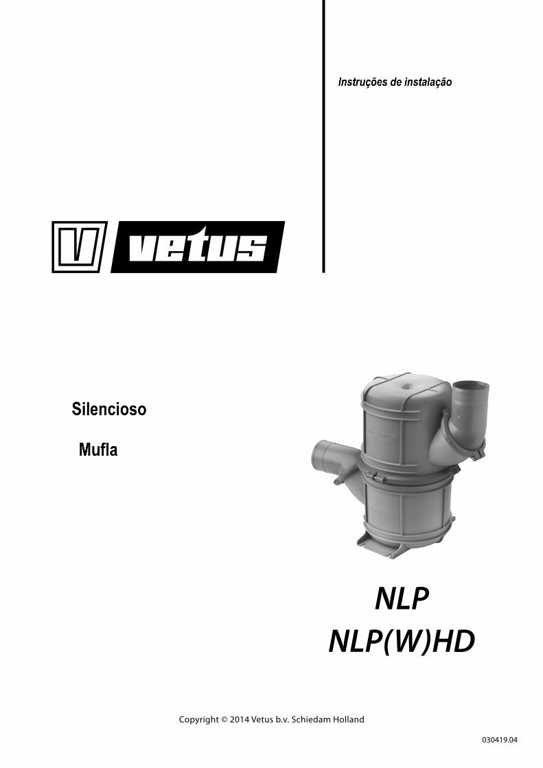
Waterlock
Waterlock
Wassersammler
Waterlock
Colector
MarmitteNLP
NLP(W)HD
Copyright © 2014 Vetus b.v. Schiedam Holland
030419.04
4 030419.04 Waterlock NLP
1 Introduction
The Vetus exhaust system components are especially suitable for use in water-injected exhaust systems.
The maximum temperature when in continuous use depends on the material used to construct the waterlock.
The material used can be recognised by its colour.
Type Colour maximum continuous operat-ing temperature
NLPxx(S) Gray 70˚C (158˚F)
NLPxx(S)HD Black250˚C (482˚F)
NLPxx(S)WHD White
t� Fit a temperature alarm to warn of excessively hot exhaust system temperature.
t� If the quantity of injected coolant water is reduced to in order to lower back-pressure in the exhaust system, check that there is still sufficient water injected when the engine is ticking-over. This will prevent excess temperatures in the exhaust system.
t� Excess temperature can also be the consequence of insuffi-cient mixing of coolant water with the exhaust gasses.
In general, good mixing is obtained by a virtually vertically installed exhaust injection bend.
Poor mixing can also occur with an engine on tick-over; es-pecially when the coolant water injection bend is installed virtually horizontally.
If necessary, take action. For example; by fitting a water vor-tex or a water splitter in the exhaust pipe, to improve the mixing of coolant water with the exhaust gasses.
With water-injected exhaust systems, fit a hose of suitable quality.
This hose must be reinforced, resistant to exhaust gasses, high tem-peratures (100 degrees C, 212 degrees F) and oil. Easy flexibility is essential for installation, while the hose must not collapse when heated.
Vetus exhaust hose fulfils all the above requirements.
WARNING
If water enters the engine from the waterlock into the exhaust system (for example: under sail when the ship rolls or pitches heavily) this will lead to irreparable damage to the engine.
Too much water in the waterlock can effect engine starting; drain off this water first. Too much water in the waterlock can be also caused by repeated starting attempts while the engine refuses to start.
2 Installation
2.1 Installing waterlock NLP
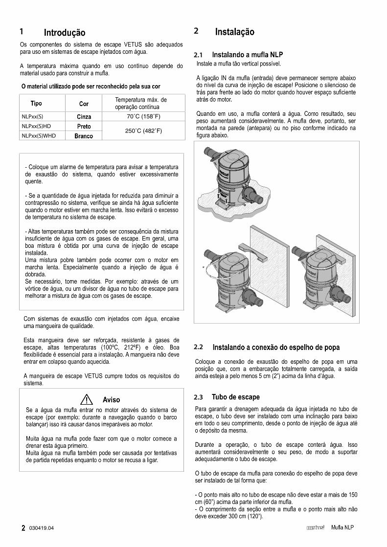
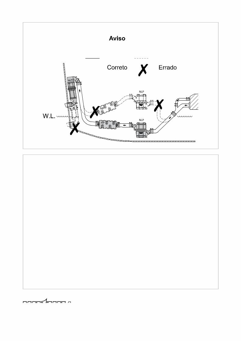
Instal the waterlock as vertical as possible.
The waterlock ‘IN’-connection must always remain below the level of the exhaust injection bend! Position the waterlock ‘back-to-front’ alongside the engine when there is insufficient space behind the en-gine.
When in use, the waterlock will contain water. As a result, its weight will increase considerably. The waterlock must therefore be mounted on the deck or a wall, as is indicated in the diagrams.
2.2 Installing the transom exhaust connection
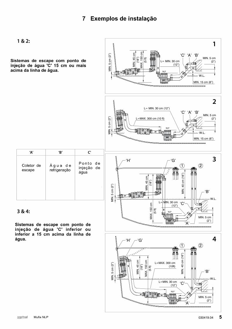
Fit the transom exhaust connection at such a position that with the ship fully laden, the outlet is still at least 5 cm (2”) above the water-line.
2.3 Exhaust pipe
In order to ensure the proper drainage of the coolant water injected into the exhaust pipe, the pipe must be installed with a slope down-ward over its whole length from the water injection point to the wa-terlock.
During operation, the exhaust pipe will contain water. This will in-crease its weight considerably, so support the exhaust pipe properly.
The exhaust pipe from waterlock to transom connection must be in-stalled in such a way that:
- The highest point in the exhaust pipe should not be more than 150 cm (60”) above the underside of the waterlock.
- The length of the section between the waterlock and the highest point, should not exceed 300 cm (120”).
030419.04 5 Waterlock NLP
ENGLISH2.4 Hose connections
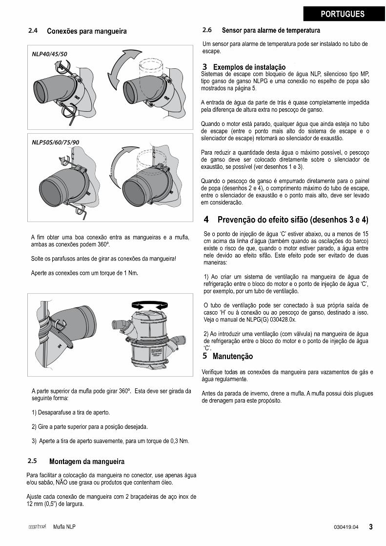
NLP40/45/50
NLP50S/60/75/90
In order to achieve the ideal connection between the hoses and the waterlock, both hose connections turn through 360 degrees.
Loosen the bolts before turning the hose connections!
Tighten the hose connections to a torque of 1 Nm (0.75 ft.lb).
The top portion of the waterlock can be turned in a 360˚ radius.
The top portion should be turned as follows:
1 Unscrew the clamping strip
2 Turn the top portion to the desired position
3 Tighten the clamping strip sufficiently, to a torque of 0.3 Nm (0.22 ft.lb).
2.5 Fitting the hose
To ease the fitting of the hose to the hose connector, use only water and/or soap, NOT grease or products containing oil.
Fit each hose connection with 2 stainless steel 12 mm (0.5”) wide hose clamps.
2.6 Sensor for temperature alarm
A sensor for a temperature alarm can be fitted in the exhaust pipe.
3 Installation Examples
Exhaust systems with a waterlock type NLP, silencer type MP, goose neck type NLPG and a transom connection are shown on page 15.
Entry of water from the aft is almost completely prevented by the extra height difference in the goose neck.
When the engine is stopped, any water which is still in the exhaust pipe (between the highest point in the exhaust system and the ex-haust silencer) will run back to the exhaust silencer.
To reduce the amount of this water as much as possible, the goose neck should be fitted directly above the exhaust silencer, if possible (see drawings 1 and 3).
When the goose neck is fitted directly to the transom (drawings 2 and 4), the maximum length of the exhaust pipe, between exhaust silencer and the highest point, should be taken into account.
4 Prevention of syphoning (drawings 3 & 4)
If the water injection point ‘C’ is below, or less than 15 cm (0.6”) above the waterline (also when the ship heels under sail), there is a risk that when the engine is stopped, the coolant water will enter the engine due to syphoning. This syphoning can be prevented in two ways:
� By creating an air vent system in the coolant water hose between engine block and water injection point ‘C’, by fitting an air vent with air vent pipe, for example.
The air vent pipe can be connected to its own hull outlet (H) or to the connection on the gooseneck intended for this, type NLPG (G). See the manual for the NLPG, no. 030428.0x.
� By fitting an air vent (with valve) in the coolant water hose be-tween the engine block and water injection point ‘C’.
5 Maintenance
Check all hose connections for gas and water leaks regularly.
Before the winter lay-up, drain the waterlock. The waterlock has two drain plugs for this purpose.
14 030419.04 Waterlock NLP
6 Hoofdafmetingen
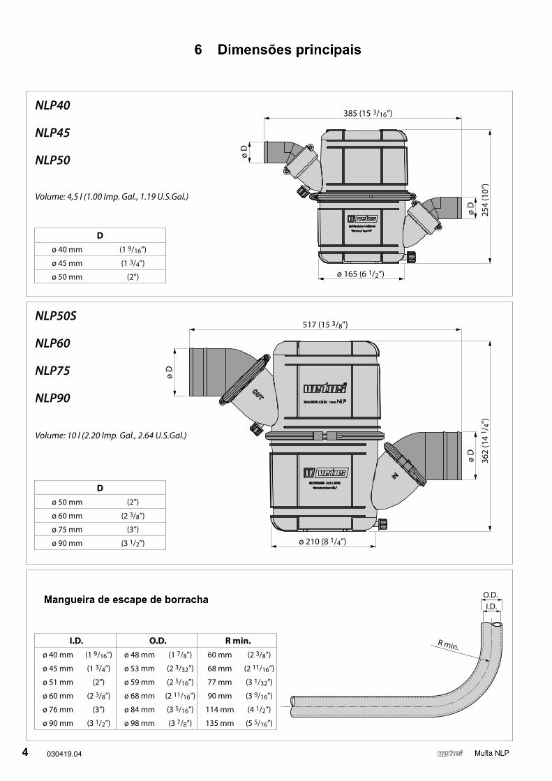
6 Principal dimensions
385 (15 3/16”)
ø 165 (6 1/2”)
254
(10”
)
ø D
ø D
NLP40
NLP45
NLP50
Volume: 4,5 l (1.00 Imp. Gal., 1.19 U.S.Gal.)
517 (15 3/8”)
ø 210 (8 1/4”)
362
(14
1 /4”
)
ø D
ø D
NLP50S
NLP60
NLP75
NLP90
Volume: 10 l (2.20 Imp. Gal., 2.64 U.S.Gal.)
Dø 50 mm (2”)
ø 60 mm (2 3/8”)
ø 75 mm (3”)
ø 90 mm (3 1/2”)
Dø 40 mm (1 9/16”)
ø 45 mm (1 3/4”)
ø 50 mm (2”)
I.D.O.D.
R min.
Rubber uitlaatslang Rubber exhaust hose Gummi Auspuffschlauch
Tuyau d’echappement neopräne Manguera de escape de goma Tubo di scappamento in gomma
6 Hauptabmessungen
6 Dimensions principales
6 Dimensiones principales
6 Dimensioni principali
I.D. O.D. R min.ø 40 mm (1 9/16”) ø 48 mm (1 7/8”) 60 mm (2 3/8”)
ø 45 mm (1 3/4”) ø 53 mm (2 3/32”) 68 mm (2 11/16”)
ø 51 mm (2”) ø 59 mm (2 5/16”) 77 mm (3 1/32”)
ø 60 mm (2 3/8”) ø 68 mm (2 11/16”) 90 mm (3 9/16”)
ø 76 mm (3”) ø 84 mm (3 5/16”) 114 mm (4 1/2”)
ø 90 mm (3 1/2”) ø 98 mm (3 7/8”) 135 mm (5 5/16”)
030419.04 15 Waterlock NLP
7 Installatievoorbeeld
7 Installation example
MIN
. 5 c
m (
2”)
L= MIN. 30 cm(12”)
MIN. 15 cm (6”)
‘A’‘C’ ‘B’
MIN
. 45
cm(1
8”)
MA
X. 1
50 c
m(5
ft)
NLPMP
MIN. 5 cm(2”)
L= MIN. 30 cm (12”)
MIN. 15 cm (6”)
‘A’‘C’ ‘B’L=MAX. 300 cm (10 ft)
MIN
. 5 c
m (
2”)
NLPMP
MIN. 5 cm(2”)
‘A’
‘C’
‘B’
1 2
MIN
. 40
cm (
16”)
MIN
. 5 c
m (
2”)
MIN
. 45
cm
(18”
)M
AX
. 150
cm
(5 ft
)
‘H’ ‘G’
L= MIN. 30 cm(12”)
NLP
MP
MIN. 5 cm(2”)
‘C’
‘B’
1 2
L=MAX. 300 cm(10ft)
MIN
. 40
cm (
16”)
MIN
. 5 c
m (
2”)
L=MIN. 30 cm(12”)
MIN
. 45
cm(1
8”)
MA
X. 1
50 c
m(5
ft)
‘H’ ‘G’
‘A’
NLPMP
MIN. 5 cm(2”)
1 & 2:Uitlaatsystemen met waterinjectiepunt ‘C’ 15 cm of meer boven de waterlijn
Exhaust systems with water-injection point ‘C’ 15 cm or more above the waterline
Auspuffsystemen mit Wasserein-spritzpunkt ‘C’ 15 cm oder mehr über der Wasserlinie
Système d’echappement avec point d’injection d’eau ‘C’ 15 cm ou plus audessus de la ligne de flot-taisson
Sistemas de escape con el punto de inyección de auga ‘C’ a 15 cms o más por encima de la línea de flotación
Sistema di scappamento con punto di iniezione dell’acqua ‘C’ 15 cm o più al di sopra della linea di galleggiamento
3 & 4:Uitlaatsystemen met waterinjectiepunt ‘C’ onder of minder dan 15 cm boven de waterlijn
Exhaust systems with water-injection point ‘C’ be-low or less than 15 cm above the waterline
Auspuffsystemen mit Wasserein-spritzpunkt ‘C’ un-ter oder weniger als 15 cm über der Wasserlinie
Système d’echappement avec point d’injection d’eau ‘C’ au-dessous ou inférieur à 15 cm au-dessus de la ligne de flottaisson
Sistemas de escape con el punto de inyección de auga ‘C’ deboja o a menos de 15 cms por encima de la línea de flotación
Sistema di scappamento con punto di iniezione dell’acqua ‘C’ meno di 15 cm al di sopra della linea di galleggiamento
2
3
4
1
7 Montagebeispiel
7 Exemple d’installation
7 Ejemplo de instalación
7 Esempio di installazione
‘A’ ‘B’ C'Uitlaatspruitstuk Koelwater Waterinjectiepunt
Exhaust manifold Cooling water Water-injection point
Auspuffkrümmer Kühlwasser Wasser-einspritz-stelle
Collecteur d’echap-pement
Eau de refroidisse-ment
Point d’injection d’eau
Empalme de escape Agua de refrige-ración
Punto de inyección de agua
Collettore di scap-pamento
Acqua di raffredda-mento
Punto di iniezione dell’acqua
030419.04 2014-07
vetus b.v.FOKKERSTRAAT 571 - 3125 BD SCHIEDAM - HOLLAND - TEL.: +31 10 4377700TELEFAX: +31 10 4372673 - 4621286 - E-MAIL: [email protected] - INTERNET: http://www.vetus.com
Printed in the Netherlands
Waarschuwing
Warning
Warnung
Avertissement
Precaución
Avvertenza
NLP
MP
GOEDRIGHTRICHTIGCORRECTCORRECTOCORRETTO
FOUTWRONGFALSCHFAUTIFFALSOSBAGLIATO
NLPMP