Embed Size (px)
Citation preview

Minnesota State Patrol Commercial Vehicle Section
Mandatory Inspection Program Certified Inspector Student Handbook
2017

i

ii
Inspector Name: ________________________________________
Certification Number: ________________________________________
Location of Course: ________________________________________
Instructor Name: ________________________________________
Scott Clarke - 507-251-4051
Pat Forster – 507-381-7808
My certification expires: ________/________/_________ month day year
WARNING
You must recertify prior to the expiration date entered above to remain certified to perform MIP inspections. If you are not recertified within six months following your expiration date, your certification will be revoked. If your certification has lapsed by more than six months, you must attend the full certification course to become recertified.

iii
MINNESOTA STATE PATROL COMMERCIAL VEHICLE INSPECTION PROGRAM
ADDRESS TO ORDER DECALS: Minnesota State Patrol 1110 Centre Pointe Curve, Suite 410 Mendota Heights, MN 55120
For the latest program updates, a list of recertification providers, or to obtain copies of forms, go to our website. dps.mn.gov/divisions/msp/commercial-vehicles
Commercial Vehicle Section automated phone system: (651) 405-6196
Category/Destination Options Description
1 MN DOT Office 1/1
Limo, Hazmat, Intrastate Authority, Intrastate Insurance filing, special Transportation Services (STS) and Intrastate Passenger Registration
1/2 Oversize Permits, Logger Permits, Permit Office
2 Mandatory Inspection Program (MIP), State Patrol
2/1 Complaints
2/2 Decal Sales and Classes
2/3 Forms and Provider Lists (on the web)
2/4 Inspection Procedure
3 Roadside Inspections, State Patrol
3/1 Inspection Request
3/2 Inspection Challenge
3/3 General Roadside Inspection Questions
4 Federal Motor Carrier Safety Administration (FMCSA) 4 Interstate US DOT Numbers and Federal Regulations
5 Prorate Office 5 Intrastate US DOT Numbers and Registration
6 School Bus & Motor Coach, State Patrol 6 School Bus & Motor Coach Questions and Complaints
7 Accident Records, DVS 7 Requesting a copy of an Accident Report
8 Non-Commercial Vehicle Questions, State Patrol 8 Non-Commercial Vehicle Questions i.e. motor cycles, RV's, driver's license
9 MN State Patrol Commercial Vehicle Section 9 District 4700 Office
Complaint Procedures: To make a complaint regarding an MIP certified inspector, mail or email a copy of the inspection report, along with a narrative explaining your complaint. Include supporting documents and/or photographs. Be sure to include your name and phone number. Send to:
Lt. Mike Theis [email protected] Fax: 651-405-6199 Minnesota State Patrol Commercial Vehicle Section 1110 Centre Pointe Curve, Suite 410 Mendota Heights, MN 55120
Complaints relating to roadside inspections should be entered online through DataQs at http://dataqs.fmcsa.dot.gov
Federal DOT Information Desk: Toll Free: 1-800-832-5660 Metro: 651-291-6150 www.fmcsa.dot.gov/
National Highway Transportation Safety Administration: www.nhtsa.dot.gov/

1
Table of Contents Definitions ..................................................................................................................................................... 5
Commercial Motor Vehicle ....................................................................................................................... 6
Commercial Motor Vehicle – (Federal Definition) .................................................................................... 6
Gross Vehicle Weight ................................................................................................................................ 6
Special Mobile Equipment ........................................................................................................................ 6
Implement of Husbandry .......................................................................................................................... 7
Bus ............................................................................................................................................................. 7
Commerce ................................................................................................................................................. 7
Exception ............................................................................................................................................... 7
Interpretation - ..................................................................................................................................... 7
Highway..................................................................................................................................................... 7
Intrastate Vehicle ...................................................................................................................................... 8
Interstate Vehicle ...................................................................................................................................... 8
Owner ....................................................................................................................................................... 8
Covered Farm Vehicle ............................................................................................................................... 8
USDOT Number ............................................................................................................................................. 9
Inspection Required .................................................................................................................................... 10
Intrastate ................................................................................................................................................. 10
Interstate................................................................................................................................................. 10
Is a Minnesota inspection required? .......................................................................................................... 11
Vehicles That Must be Inspected and Display a Current Minnesota MIP Decal ..................................... 12
Is a federal inspection required? ................................................................................................................ 13
Vehicles That Must be Inspected per Federal Regulations ..................................................................... 14
Who May Inspect? ...................................................................................................................................... 14
Certification............................................................................................................................................. 15
Who May Inspect (continued) .................................................................................................................... 16
Suspensions and Revocations ................................................................................................................. 16
Inspection Report .................................................................................................................................... 17
Required Record Keeping ....................................................................................................................... 17
Inspection Report Guidelines ...................................................................................................................... 18
Vehicle Inspection Report Information Form Guidelines ........................................................................... 19
Inspection Decals ........................................................................................................................................ 23
Replacement of MIP Decal ...................................................................................................................... 23
Reviews, Random Inspections and Audits .................................................................................................. 23

2
Violations and Penalties .......................................................................................................................... 23
Develop a Good Procedure ......................................................................................................................... 24
Brake System ............................................................................................................................................... 25
Antilock Braking System .......................................................................................................................... 26
Vehicles required to be equipped with ABS: ...................................................................................... 26
ABS is not required on: ....................................................................................................................... 26
Automatic Brake Adjusters ..................................................................................................................... 26
Service Brakes ......................................................................................................................................... 27
Measuring brake pushrod stroke ............................................................................................................ 28
Clamp Type Brake Chamber Data ....................................................................................................... 30
Long Stroke Clamp Type Brake Chamber Data ................................................................................... 30
Tie Rod Style Piston Brake Chamber Data .......................................................................................... 31
Bolt Type Brake Chamber Data ........................................................................................................... 31
Roto Chamber Data ............................................................................................................................. 31
DD-3 Brake Chamber Data .................................................................................................................. 31
Wedge Brakes ......................................................................................................................................... 32
Brake Linings or Pads .............................................................................................................................. 33
Brake Linings – Non-steering Axles ..................................................................................................... 33
Brake Linings – Steering Axles ............................................................................................................. 33
Missing Brakes .................................................................................................................................... 34
Mismatch Brakes ................................................................................................................................. 34
Parking Brake System .............................................................................................................................. 34
Agricultural Commodity Trailer ........................................................................................................... 34
Heavy Hauler Trailer ........................................................................................................................... 34
Pulpwood Trailer ................................................................................................................................. 35
Brake Drums or Rotors ............................................................................................................................ 35
Brake Hose .............................................................................................................................................. 35
Brake Tubing ........................................................................................................................................... 35
Low Pressure Warning Device ................................................................................................................ 35
Tractor Protection Valve ......................................................................................................................... 36
Inspection Procedure for the Tractor Protection Valve ...................................................................... 36
Breakaway Braking Requirements for Trailers ....................................................................................... 37
Checking Breakaway Brakes ................................................................................................................... 37
Air Brakes ............................................................................................................................................ 37
Vacuum Over Hydraulic Brakes ........................................................................................................... 37

3
Air Over Hydraulic Brakes ................................................................................................................... 37
Electric Brakes ..................................................................................................................................... 37
Air Compressor ....................................................................................................................................... 38
Electric Brakes ......................................................................................................................................... 38
Hydraulic Brakes ..................................................................................................................................... 38
Hydraulic Brakes (cont.) .......................................................................................................................... 39
Surge brakes on trailers .......................................................................................................................... 39
Surge Brake Inspections: ..................................................................................................................... 39
Testing Surge Brakes: .......................................................................................................................... 40
Testing Breakaway Brake Function (on trailer with surge brakes): .................................................... 40
Vacuum Systems ..................................................................................................................................... 40
Coupling Devices ......................................................................................................................................... 43
Fifth Wheel .............................................................................................................................................. 43
Pintle Hook .............................................................................................................................................. 45
Drawbar/Tow bar Eye ............................................................................................................................. 45
Drawbar/Tow bar Tongue ....................................................................................................................... 45
Ball hitches .............................................................................................................................................. 46
Safety Devices/Safety Chain Requirements ............................................................................................ 46
Saddle Mounts ........................................................................................................................................ 50
Exhaust System ........................................................................................................................................... 50
Fuel System ................................................................................................................................................. 50
Lighting Devices .......................................................................................................................................... 51
Warning flags on projecting loads .......................................................................................................... 54
Conspicuity Treatment Requirements .................................................................................................... 55
Marking of Lenses and Light Fixtures...................................................................................................... 56
Safe Loading ................................................................................................................................................ 64
Steering Mechanism ................................................................................................................................... 64
Steering wheel free play ......................................................................................................................... 64
Steering Column ...................................................................................................................................... 65
Front Axle Beam and All Other Components .......................................................................................... 65
Steering Gear Box ................................................................................................................................... 65
Pitman Arm ............................................................................................................................................. 66
Power Steering ........................................................................................................................................ 66
Ball and Socket Joints .............................................................................................................................. 66
Tie Rods and Drag Links .......................................................................................................................... 66

4
Steering System ...................................................................................................................................... 66
Suspension .................................................................................................................................................. 67
Frame .......................................................................................................................................................... 68
Tires ............................................................................................................................................................. 69
Any tire on any steering axle of a power unit ......................................................................................... 69
All tires other than on the steering axle of a power unit........................................................................ 70
Tires on all axles ...................................................................................................................................... 70
Wheels and Rims ......................................................................................................................................... 70
Windshield Glazing...................................................................................................................................... 71
Windshield Condition .............................................................................................................................. 71
Coloring or Tinting of Windshields and Windows................................................................................... 71
Prohibition on Obstructions to the Driver’s Field of View ...................................................................... 71
Windshield Wipers, Washers, and Defrosters ............................................................................................ 72
Motorcoach Seats ....................................................................................................................................... 72
Additional Inspection Items ........................................................................................................................ 73
Rear Vision Mirrors ................................................................................................................................. 73
Horn ........................................................................................................................................................ 73
Fire Extinguisher ..................................................................................................................................... 73
Warning Devices for Stopped Vehicles ................................................................................................... 73
Rear Impact Guards and Rear End Protection ........................................................................................ 74
General requirements ............................................................................................................................. 77
Trailers/semitrailers manufactured on/after January 26, 1998 ......................................................... 77
Motor vehicles manufactured after December 31, 1952 ................................................................... 78
Driveline/Driveshaft ................................................................................................................................ 79
Special Provisions – Minnesota requirements/exemptions ....................................................................... 80
Wheel Flaps on Trucks and Trailers ........................................................................................................ 80
Vehicles generally ............................................................................................................................... 80
Alternative requirements. ................................................................................................................... 80
Extended flaps. .................................................................................................................................... 80
Vehicle with conveyor belt. ................................................................................................................ 80
Bottom-dump vehicle. ........................................................................................................................ 80
Wheel flaps – rear-end dump farm trucks .............................................................................................. 81
Rear End Protection – certain agriculture trucks .................................................................................... 81
Cab & Body Components ........................................................................................................................ 81
Bus/Motor Coach .................................................................................................................................... 81
5
Instructions for Use of Decals ..................................................................................................................... 82
General Guidelines .................................................................................................................................. 82
Decal Placement ..................................................................................................................................... 82
Trucks and Truck-tractors: .................................................................................................................. 82
Trailers: ............................................................................................................................................... 82
Buses: .................................................................................................................................................. 82
Alternate location for decal .................................................................................................................... 82
Change of Information ................................................................................................................................ 83
Index............................................................................................................................................................ 84

6
Definitions
Commercial Motor Vehicle For purposes of the Minnesota Mandatory Inspection Program, commercial motor vehicle means a motor vehicle or combination of motor vehicles used to transport passengers or property if the motor vehicle:
1. has a gross vehicle weight of more than 26,000 pounds; 2. is a vehicle in a combination of more than 26,000 pounds; 3. is a bus; 4. is of any size and is used in the transportation of hazardous materials that are
required to placard under Code of Federal Regulations, title 49, parts 100-185;
Commercial Motor Vehicle does not include:
1. a school bus or Head Start bus displaying a certificate under section 169.451; 2. a bus operated by the Metropolitan Council or by a local transit commission created
in chapter 458A.
Commercial Motor Vehicle – (Federal Definition) Commercial motor vehicle means any self-propelled or towed vehicle used on public highways in interstate commerce to transport passengers or property when:
1. The vehicle has a gross vehicle weight rating or gross combination weight rating of 10,001 pounds or more;
2. is a bus; 3. transports hazardous material requiring placarding.
Gross Vehicle Weight Gross vehicle weight means the greater of:
1. the unloaded weight of a vehicle or the unloaded weight of a truck-tractor and semi-trailer combination, plus the weight of the load; or
2. the value specified by the manufacturer as the maximum gross weight or gross vehicle weight rating (GVWR)
Special Mobile Equipment 1. “Special mobile equipment” means every vehicle not designed or used for the
transportation of persons or property and only incidentally operated or moved over a highway, except vehicles described in paragraph (b). Special mobile equipment includes, but is not limited to: ditch-digging apparatuses, pump hoists and other water well-drilling equipment registered and licensed under chapter 103I, other road construction or road maintenance machinery, aggregate processing and
NOTE: DO NOT USE THE REGISTERED GROSS WEIGHT DISPLAYED ON THE LICENSE PLATE.

7
conveying equipment, truck-mounted log loaders that are used exclusively for commercial logging and self-propelled cranes (are not required to have a license plate).
2. “Special mobile equipment” does not include: (1) machinery that has been temporarily or permanently mounted on a commercial motor vehicle chassis that is used only to provide a service and is not able to haul goods for resale; or (2) dump trucks.
Implement of Husbandry Implement of Husbandry means a self-propelled or towed vehicle designed or adapted to be used exclusively for timber-harvesting, agricultural, horticultural, or livestock-raising operations. (These vehicles are not required to be inspected).
Bus Bus means every motor vehicle designed for carrying more than 15 passengers including the driver and used for the transportation of persons.
Commerce Commerce means the transportation of person or property for a fee (for hire carrier), or the transportation of persons or property in the furtherance of another business (private carrier).
Exception - The occasional transportation of personal property by individuals not for compensation or in the furtherance of a commercial enterprise.
Interpretation - Question 21: Does the exemption in 390.3(f)(3) for the occasional transportation of personal property by individuals not for compensation or in the furtherance of a commercial enterprise apply to persons who occasionally use CMV’s to transport cars, boats, horses, etc. to races, tournaments, shows or similar events, even if prize money is offered at these events?
Guidance: The exemption would apply to this kind of transportation, provided: (1) the underlying activities are not undertaken for profit, i.e., (a) prize money is declared as ordinary income for tax purposes and (b) the cost of the underlying activities are not deducted as a business expense for tax purposes; and, where relevant; (2) corporate sponsorship is not involved.
Highway Highway means any road, street, or way, whether on public or private property, open to public travel. “Open to public travel” means that the road section is available, except during scheduled periods, extreme weather or emergency conditions, passable by four-wheel standard passenger cars, and open to the general public for use without restrictive gates, prohibitive signs, or regulation other than restrictions based on size, weight, or class of registration. Toll plazas of public toll roads are not considered restrictive gates.

8
Intrastate Vehicle Intrastate vehicle means a vehicle used in commerce used only in one state and never crosses a state line.
Intrastate Interstate
Interstate Vehicle Interstate vehicle means a vehicle used in commerce that crosses any state line, or will be crossing state lines.
Owner Owner means a person who owns, or has control, under a lease of more than 30 days’ duration, of one or more commercial motor vehicles.
Covered Farm Vehicle A covered farm vehicle is a commercial motor vehicle that:
1. Is operated by a farmer, family member or employee of the farmer; 2. Used to transport to or from a farm:
a. Agricultural commodities b. Livestock c. Machinery or supplies;
3. Displays a farm plate; and 4. Has a gross vehicle weight of:
a. 26,001 lbs. or less and traveling anywhere in the United States; or b. greater than 26,001 lbs. and traveling anywhere within its home state; or c. when crossing state lines, is greater than 26,001 pounds and operated within
150 air miles of the farm or ranch. 5. Is not used in for-hire carrier operations; 6. Is not used in the transportation of hazardous materials in a quantity requiring the
vehicle to display placards.

9
USDOT Number A vehicle or a combination of vehicles with a GVW or combined GVW of 10,001 pounds or more used in commerce must have displayed thereon a USDOT number and the legal name or single trade name of the motor carrier operating the self-propelled CMV, as listed on the motor carrier identification report (Form MCS-150).
Size, shape, location, and color of marking must 1. appear on both sides of the self-propelled CMV; 2. be in letters that contrast sharply in color with the background on which the letters
are placed; 3. be readily legible during daylight hours from a distance of 50 feet (15.24 meters)
while the CMV is stationary; and 4. be kept and maintained in a manner that retains the legibility required by (3) of this
section.
This section does not apply to 1. a farm truck that is used in intrastate commerce 2. a vehicle that is not used in commerce, or 3. a vehicle that is owned and used solely in the transaction of official business by the
federal government, the state, or any political subdivision.
10
Inspection Required It is unlawful for a person to operate or permit the operation of the following vehicles unless such vehicle displays a valid safety inspection decal issued by an inspector certified by the commissioner.
1. A commercial motor vehicle registered in Minnesota (Note: this includes vehicles with a 21 day temporary registration permit)
2. Special mobile equipment as defined in section 168.002, subdivision 31, which is self-propelled, if it is mounted on a commercial motor vehicle chassis.
NOTE: Fire trucks and emergency response vehicles which are not required to be registered and display license plates in Minnesota, are not required to be inspected and display an annual inspection decal.
NOTE: A covered farm vehicle is exempt from the annual inspection requirements and is not required to display an annual inspection decal. Covered farm vehicles are required to comply with laws and regulations regarding parts and accessories necessary for safe operation.
Intrastate Self-propelled special mobile equipment mounted on a CMV chassis must be inspected and display a Minnesota mandatory inspection program (MIP) decal when the GVW is greater than 26,000 pounds, or when used in combination and the combined GVW is greater than 26,000 pounds.
Both units of a combination consisting of self-propelled special mobile equipment towing a registered vehicle must be inspected and display an MIP decal when the combined GVW is greater than 26,000 pounds.
Towed special mobile equipment that is not required to be registered is not required to be inspected or to display an MIP decal.
Special mobile equipment that does not meet the definition of a commercial vehicle must meet all of the equipment requirements, but is not required to have an inspection form or MIP decal.
Interstate Every vehicle with a gross vehicle weight rating (GVWR) or a combination of vehicles with a gross combination weight rating (GCWR) of 10,001 or more pounds involved in interstate commerce must show proof that the vehicle or vehicles have passed an annual inspection. This includes special mobile equipment.

11
Is a Minnesota inspection required?
IS THE VEHICLE OR COMBINATION: • GREATER THAN 26,000 POUNDS, • A BUS, OR • REQUIRED TO BE PLACARDED,
AND • DISPLAYING MINNESOTA LICENSE PLATES,
OR • SPECIAL MOBILE EQUIPMENT ON A CMV
CHASSIS?
NO
NO MINNESOTA INSPECTION IS REQUIRED IF
USED INTRASTATE ONLY. SEE FEDERAL INSPECTION REQUIREMENTS
ABOVE FOR INTERSTATE USE.
INTRASTATE OR INTERSTATE
MUST BE INSPECTED AND DISPLAY A MINNESOTA
DECAL.
YES

12
Vehicles That Must be Inspected and Display a Current Minnesota MIP Decal Vehicles registered in Minnesota
Single unit with GVW greater than 26,000 pounds, including self-propelled special mobile equipment
Two or more units with combined GVW greater than 26,000 pounds, including self-propelled special mobile equipment.
A bus designed to transport more than 15 passengers, including the driver.
A vehicle of any size transporting hazardous materials in a quantity requiring placards.

13
Is a federal inspection required?
IS THE VEHICLE OR COMBINATION GREATER THAN
10,000 POUNDS, A BUS, OR REQUIRED TO BE PLACARDED?
NO INSPECTION IS REQUIRED
IS THE VEHICLE USED IN INTERSTATE COMMERCE
AN INSPECTION IS REQUIRED
YES
YES NO
NO

14
Vehicles That Must be Inspected per Federal Regulations When involved in Interstate Commerce
Single unit with GVW of 10,001 more pounds
A combination of two or more vehicles with a GVW of 10,001 or more pounds
A bus designed to transport more than 15 passengers, including the driver.
A vehicle of any size transporting hazardous materials in a quantity requiring placards.

15
Who May Inspect? An inspection required by this section may be performed by a person who has been certified by the commissioner after having received training provided by the State Patrol or other training approved by the commissioner.
Certification A person may be certified by the commissioner to conduct Minnesota annual inspections if the person is:
1. an owner, or employee of the owner, of one or more commercial motor vehicles that are power units;
2. a dealer licensed under section 168.27 and engaged in the business of buying and selling commercial motor vehicles, or an employee of the dealer;
3. engaged in the business of repairing and servicing commercial motor vehicles; or 4. employed by a governmental agency that owns commercial vehicles.
Note: Inspectors are required to inform the State Patrol immediately of any changes of employment, business address, change of business name etc. If you no longer meet the criteria above due to loss of job, layoff, etc., you cannot conduct Minnesota annual inspections.
To qualify as a business of repairing and servicing commercial vehicles you must meet all of the following requirements.
1. You must be in the business of repairing and servicing of commercial vehicles. This must be your primary business, not that you occasionally work on commercial vehicles.
2. You must have a building or mobile repair vehicle. Either must be properly equipped to repair or service commercial vehicles.
3. You must advertise as a commercial vehicle repair business “OPEN TO THE PUBLIC”. This would include a sign on or in front of the building, business phone number, and invoices with the business letterhead or logo. For a mobile repair vehicle there would have to be signs on the vehicle with the name of the business, address and phone number.
IF YOU DO NOT MEET ALL THE REQUIREMENTS LISTED ABOVE, YOU ARE IN VIOLATION. ALL INSPECTIONS YOU
PERFORM WOULD BE INVALID. YOUR CERTIFICATION MAY BE SUSPENDED, REVOKED OR CANCELED.

16
Who May Inspect (continued) Minnesota annual inspection certification is effective for two years from the date of certification. The commissioner may require biennial retraining of persons holding a certificate as a condition of renewal of the certificate.
A certified inspector may charge a reasonable fee for each inspection of a vehicle not owned by the person or the person’s employer. Except as otherwise provided, the standards adopted by the commissioner for commercial motor vehicle inspections under section 169.781 to 169.783 must be the standards prescribed in 49 Code of Federal Regulations, section 396.17, and in chapter III, subchapter B, appendix G.
NOTE: Certified inspectors must do the majority of their inspections at the place of business where they are employed. Certified inspectors may occasionally inspect other vehiclesoutside of their place of employment, i.e. vehicles owned by a relative, neighbor, or friend. However, this would not allow a person to start an inspection business. The liability for these inspections would lie with the inspector and if an inspection were not done properly, the inspector’s certificate may be suspended or revoked. The inspector would lose thecertification to perform any inspections including at his primary place of employment.
Suspensions and Revocations The commissioner, after notice and an opportunity for a hearing, may suspend a certificate for:
1. failure to meet biennial certification requirements prescribed by the commissioner. You must attend and pass a recertification course prior to expiration of the certification. If you do not, you will be suspended from doing inspections or purchasing decals.
2. failure to inspect commercial motor vehicles in accordance with inspection procedures established by the State Patrol.
Examples: Failure to properly inspect vehicles, complete inspection reports, or application of the decal; fail to notify the State Patrol immediately of any change of employment, job change, etc.
The commission shall revoke a certificate if
1. you do not attend and pass a recertification course within six months following the expiration of your certification.
2. the commissioner determines after notice and an opportunity for a hearing the certified person issued an inspection decal for a commercial motor vehicle when the person knew or reasonably should have known the vehicle was in such a state of repair it would have been declared OUT-OF-SERVICE if inspected by an employee of the State Patrol.
Suspension and revocation of certificates under this subdivision are not subject to section §14.57 to 14.69 (right to trial by jury).

17
Inspection Report A person performing an inspection shall issue an inspection report (pass or fail) to the owner of the commercial motor vehicle inspected. The report must include:
• the full name of the person performing the inspection, (clearly printed) and the inspector certification number;
• the name of the owner of the vehicle and, if applicable, the USDOT number issued to the owner of the vehicle, or to the operator of the vehicle if other than the owner;
• the vehicle identification number (the entire VIN) and, if applicable, the license plate number;
• the date and location of the inspection; • the vehicle components inspected and a description of the findings of the inspection,
including identification of the components not in compliance with Minnesota Statutes and/or Federal Motor Carrier Safety Regulations (Appendix G); and
• the inspector’s certification (signature) that the inspection was complete, accurate, and in compliance with the requirements of this section.
Required Record Keeping
The OWNER of the vehicle must retain a copy of the inspection report for at least 14 months at a location in the state where the vehicle is domiciled or maintained.
The INSPECTOR must maintain a copy for 14 months following the inspection in a location in the state where the inspector conducts business. During this period, the report must be available for inspection by an authorized federal, state, or local official.
NOTE: Although there is no requirement to keep a copy of the inspection report in the vehicle, it is recommended if the vehicle is going to be used in interstate commerce.
The commissioner shall prescribe the form of the inspection report and revise it as necessary to comply with state and federal law and regulations.
ONLY THE OFFICIAL FORMS SHALL BE USED.
EFFECTIVE JANUARY 1, 2017, CERTIFIED INSPECTORS HAVE THE OPTION TO USE THE TRADITIONAL HANDWRITTEN FORM
OR AN ELECTRONIC VERSION OF THE INSPECTION REPORT FORM THAT IS AVAILABLE ON THE STATE PATROL WEBSITE. WHEN THE E-FORM (ADOBE ACROBAT) IS USED IN LIEU OF THE HANDWRITTEN FORM:
• THE FORM MUST BE DIGITALLY SIGNED • A PRINTED COPY MUST BE PROVIDED TO THE VEHICLE’S OWNER (PASS OR FAIL) • THE INSPECTOR’S COPY MAY BE PRINTED OR SAVED ELECTRONICALLY • THE COMPLETED FORMS MUST BE CAPABLE OF BEING DISPLAYED AND/OR PRINTED AND PROVIDED TO
STATE PATROL MIP AUDITORS UPON DEMAND

18
Inspection Report Guidelines 1. INSPECTION DATE: Enter month, day and year, i.e. January 1, 2012, 01/01/2012
2. INSPECTION LOCATION: Enter street address or enter a physical description.
3. INSPECTION CITY, STATE, ZIP: Enter city, state, ZIP of inspection location.
4. TIME INSPECTION WAS STARTED: Enter time inspection was STARTED as hhmm, i.e. 0745, check AM/PM.
5. TIME INSPECTION COMPLETED: Enter the time the inspection was completed as hhmm, check AM/PM.
6. VEHICLE MAKE: Enter manufacturer name. (Use same abbreviation that is on cab card)
7. MODEL YEAR: Enter model year of vehicle, using four digits, i.e. 1998.
8. VIN NUMBER: Enter the complete vehicle identification number taken from vehicle identification plate. For special mobile equipment, if there is not a make or a VIN enter the type of vehicle (such as cement mixer). The carrier should assign a unit number to the vehicle.
9. UNIT NUMBER: Enter company assigned unit number.
10. ODOMETER READING: Enter seven digits. Check “H” for Hub; “C” for Cab. If odometer does not work, make a note, such as “inoperative”.
11. LICENSE NUMBER: Enter vehicle’s base state license plate number including all letters and numbers.
12. STATE: Enter state of base license plate (use standard two letter abbreviation).
13. DECAL NUMBER: Enter serial number of decal placed on vehicle.
14. OWNER OF VEHICLE: Enter name of owner of vehicle.
15. OWNER STREET ADDRESS: Enter owner’s business address.
16. OWNER CITY, STATE, ZIP: Enter owner’s city, state and zip.
17. CARRIER NAME: Enter full name of the carrier or entity operating the vehicle as determined from shipping documents, log book, vehicle registration, cab card, etc. If a leased vehicle, use the name of the lessee. Abbreviations are not to be used unless the proper legal name of the entity is abbreviated.
18. CARRIER STREET ADDRESS: Enter full address where the carrier’s home office or headquarters is located.
19. CARRIER CITY, STATE, ZIP: Enter the carrier’s city, state and ZIP.
20. OWNER USDOT NUMBER: Enter USDOT number assigned to the vehicle owner, if applicable.
21. CARRIER USDOT NUMBER: Enter USDOT number assigned to the carrier, if applicable. A vehicle does not fail an inspection if it does not have a USDOT number.
22. INSPECTOR NAME: Print inspector’s name.
23: INSPECTOR NUMBER: Enter assigned inspector certification number.
• After inspecting each item, initial or check () the appropriate box (pass, fail or N/A).Any item not required or not present should be marked N/A (Not Applicable).
• If all items pass, enter the decal number in Box #13 and affix the decal at the proper location on the vehicle inspected.
• If any item fails, enter FAIL in place of the decal number in Box #13. • Sign the form certifying all entries are true and accurate

13. Decal #
1. Date mm/dd/yyyy 2.Insp.Location (Street Address) 3. City, State ZIP 4.Time in 5. Time Out
am pm am
pm 6.Veh Make 7.Year 8.VIN 9. Unit # 10.Odometer 11.Lic# 12.State
C H
14.Owner Name 15.Owner Street Address 16. City, State, ZIP 17.Carrier Name 18.Carrier Street Address 19.City, State, ZIP 20.Owner USDOT# 21. Carrier USDOT# 22.Inspector Name 23.Inspector # PASS FAIL N/A PASS FAIL N/A 1. BRAKE SYSTEM 5. LIGHTING DEVICES
a. Service Brakes a. Headlamps
1.) Adjustment b. Tail lamps
2.) Pads c. Brake lamps
b. Parking Brake System d. Turn Signals
c. Brake Drum or Rotors e. Marker/ID/Clearance Lamps
d. Brake Hose f. Conspicuity Tape/Reflectors
e. Brake Tubing 6. LOAD SECUREMENT
f. Low Pressure/Vacuum/or Low Air Warning Device 7. STEERING MECHANISM
g. Tractor Protection Valve a. Steering Wheel Free Play(Lash)
h. Air Compressor b. Steering Column
i. Electric Brakes c. Front Axle Beam & All Components Other Than Steering
j. Hydraulic Brakes ( including power assist) d. Steering Gear Box Column
k. Vacuum Systems e. Pitman Arm
l. ABS f. Power Steering
1. Power Unit Warning Light g. Ball & Socket Joints
2. Towed Unit Warning Light h. Tie Rods & Drag Link
3. System malfunction i. Nuts
m. Automatic Slack Adjusters j. Steering System
n. Breakaway Brakes - trailers 8. SUSPENSION
a. U-Bolts
2. COUPLING DEVICES b. Spring Assembly
a. 5th Wheel & Mounting/King Pin c. Torque, Radius, or Tracking Components
b. Pintle Hooks & Mounting Ball hitch 9. FRAME/INCLUDING CROSS FRAMES
c. Drawbar /Towbar Eye a. Frame Members
d. Drawbar/Towbar Tongue b. Tire & Wheel Clearance
e .Safety Devices (chains, cables, hooks) c. Adjustable Axle Assemblies (sliding subframes) & Locking Devices
f. Saddle Mounts 10. TIRES
g. Locking Devices 11. WHEELS & RIMS
a. Lock or Slide Ring (Split Rim)
3. EXHAUST SYSTEM b. Wheels & Rims
c. Fasteners (lugs)
4. FUEL SYSTEM d. Welds
a. Visible Leak 12. WINDSHIELDS/Glazing
b. Fuel Cap 13. WIPERS/WASHER & DEFROSTERS
c. Securement of Tank 14. MOTORCOACH SEATS
15. REAR VISION MIRRORS 19. REAR END PROTECTION
16. HORN 20. HOOD, FRONT BUMPER, BODY PARTS
17. FIRE EXTINGUISHER 21. WHEEL FLAPS
18. EMERGENCY WARNING DEVICES 22. DRIVELINE/DRIVESHAFT
THIS VEHICLE IS IN COMPLIANCE WITH 49 CFR 396.17 APPENDIX G I hereby certify that the above information is true and accurate.
Inspector Signature
This is the only vehicle inspection form approved by the Minnesota State Patrol (01/01/2017)

20
Vehicle Inspection Report Information Form Guidelines
This form is required to be completed and attached to the inspector’s copy of each inspection report. A copy must also be provided to the vehicle owner. Both inspector and owner must retain a copy, along with the inspection report, for a period of 14 months. Each document must be made available to enforcement personnel upon request.
All portions of the form must be completed, unless the item is not applicable to the vehicle being inspected. In those cases, N/A (not applicable) shall be entered; including:
INSPECTION DATE
TIME INSPECTION WAS COMPLETED
VEHICLES LICENSE NUMBER
DECAL NUMBER APPLIED TO THE VEHICLE
INSPECTOR’S NAME (PRINTED)
BRAKE CHART – Enter the brake chamber type, size, design, and measured brake stroke.
Chamber type and size can be entered as:
Clamp = C
Roto Chamber = R
Bolt = B
Wedge = W
Air Disc = AD
Hydraulic brakes = H
Electric brakes = E
Examples:
Clamp 30 Chamber = C-30
Long Stroke Chamber = C-30L or C-24L3
Push Rod Stroke - enter the actual measurement you recorded when measuring the push rod stroke.
TIRE CHART – in the appropriate boxes, enter the tire size for each tire, the minimum (lowest) major
tread depth measurement you can find on each tire, and the tire pressure for each tire.
STEERING – Enter the steering wheel diameter and the measured free play.
FIFTH WHEEL – Enter play at any of the three required measuring points on the fifth wheel assembly.
SEMI-TRAILER USED FOR FIFTH WHEEL PLAY – Enter the trailer license number and state.
TRACTOR PROTECTION VALVE – Enter pressure at which tractor protection valve activates.
SAFETY DEVICES – Circle the type of safety device, and enter the size and grade of device.
SURGE BRAKES – If inspecting a trailer with surge brakes, enter the license number and GVWR of the
towing vehicle used for the inspection, and the license number and GVWR of the trailer.
BUS & MOTOR COACH EMERGENCY EXITS AND PUSHOUT WINDOWS – check as applicable.

PERIODIC VEHICLE INSPECTION INFORMATION FORM L
eft
Rig
ht
Lef
t R
ight
Inspector
Date:O
utsi
de
Insi
de
Insi
de
Out
side
Time: Veh. Lic.# Decal # Name:
BRAKE ADJUSTMENT Chamber Type/Size
Pushrod Stroke (in.)
Axle # 1 2 3 4 5 6 7
Pushrod Stroke (in.)
Chamber Type/Size
TIRE INFORMATION
Tire Size
Min. Tread
PSI
Min. Tread
PSI
Axle # 1 2 3 4 5 6 7
Min. Tread
PSI
Min. Tread
PSI
Tire Size
5thBrakes Steering Wheel Measurements (in.)
Electric Surge Wheel diameter: ________________ Pivot Pin/Bracket:________________
Controller Free Play (in.):___________________ Slider/Base:_____________________ Make/Model:____________________
Upper/Lower Halves: _____________ Tow Vehicle Tractor Protection Valve
Tractor/Trailer used for Test Lic. Plate: ____________ State:______ Activates at (PSI): _______________ GVWR:______________ Lic. Plate: ____________ State:_____
Trailer Safety Devices Motor Coaches
Lic. Plate:____________ State:______ Chain Cable Emergency Exits/Push-out Windows:
GVWR:______________ Size:___________Grade:_______ Pass Fail NA
Notes:
I hereby certify the information contained herein is true and accurate: ________________________________________ Inspector signature

22
PERIODIC VEHICLE INSPECTION DECAL LOG
All decals purchased by a certified inspector must be listed and issued in sequential order.
INSPECTOR NAME: ________________ INSPECTOR #: _____________ DECAL YEAR: _________
DECAL# DATE ISSUED LICENSE # REPLACED/DESTROYED

23
Inspection Decals
A person inspecting a commercial motor vehicle shall issue an inspection decal for the vehicle if each inspected component complies with federal motor carrier safety regulations.
• The decal must state in the month specified on the decal, the vehicle was inspected and each inspected component complied with federal motor carrier safety regulations.
• The decal is valid for 12 months following the last day of the month specified on the decal.
• The Commissioners of Public Safety and Transportation shall make decals available, at a fee of not more than $2 for each decal, to persons certified to perform inspections.
Important: Decals are issued to inspectors by serial number and are not transferable. Decals are the property of the inspector.
Replacement of MIP Decal You may replace a valid damaged or destroyed MIP decal without re-inspecting the vehicle only if you performed the original inspection. You MAY NOT replace any other decal. Record the replacement decal, date, and license number in your inspection decal log. In column 4, record the serial number of the destroyed decal. Punch the month of the original inspection on the replacement decal, and attach the decal in the proper location.
Reviews, Random Inspections and Audits
Employees of the State Patrol and motor transportation representatives of the Department of Transportation may review records required to be kept under MS 169.781, Subdivision 6, and conduct random vehicle inspections and audits at the facility of an owner of a commercial motor vehicle.
Violations and Penalties A violation of the annual inspection statutes is a misdemeanor and punishable by a fine of up to $1000 and/or 90 days in jail.

24
Develop a Good Procedure If you follow the same procedure on every vehicle you inspect, it will save you time, you’ll be less likely to overlook inspection items, and if you get interrupted, you will know where to continue. You’ll find a consistent inspection procedure will make the process much more efficient and will make you a better inspector.

25
Appendix G
A VEHICLE DOES NOT PASS AN INSPECTION IF IT HAS ANY OF THE FOLLOWING DEFECTS OR DEFICIENCIES:
Brake System
Brakes should not be adjusted before starting the inspection If brakes are present, they must work and must be inspected* Trailers with a gross vehicle weight of 3,000 pounds or more are required to have brakes on all
wheels Breakaway brakes are required on all trailers required to be equipped with brakes

26
Antilock Braking System
Vehicles required to be equipped with ABS: Truck-Tractors with air brake systems manufactured on or after March 1, 1997 All other commercial vehicles with air brakes manufactured on or after March 1, 1998 Trucks and buses with hydraulic brake systems manufactured on or after March 1, 1999
1. Missing ABS malfunction indicator components (i.e., bulb, wiring, etc.). 2. ABS malfunction indicator that does not illuminate when power is first applied to the
ABS controller (ECU) during initial power up. 3. ABS malfunction indicator that stays illuminated while power is continuously applied to
the ABS controller (ECU). 4. ABS malfunction indicator lamp on a trailer or dolly does not cycle when electrical
power is applied: a. Only to the vehicle’s constant ABS power circuit, or b. Only to the vehicle
5. With its brakes released and its ignition switch in the normal run position, power unit does not provide continuous electrical power to the ABS on any vehicle it is equipped to tow.
6. Other missing or inoperative ABS components.
ABS is not required on: Any vehicle equipped with an axle that has a gross axle weight rating (GAWR) of 29,000
pounds or more. A heavy haul trailer with GVWR of more than 120,000 pounds. A load divider dolly
Automatic Brake Adjusters
1. Failure to maintain a brake within the brake stroke limit specified by the vehicle manufacturer.
2. Any automatic brake adjuster that has been replaced with a manual adjuster. 3. Damaged, loose, or missing components. 4. Any brake that is found to be out of adjustment on initial inspection must be evaluated
to determine why the automatic brake adjuster is not functioning properly and the problem must be corrected in order for the vehicle to pass the inspection. It is not acceptable to manually adjust automatic brake adjusters without first correcting the underlying problem. For example, there may be other components within the braking system that are distressed or out of specification (i.e., broken welds, loose mounting hardware, cracked brake drums, worn bushings, etc.) that would require immediate attention.

27
Service Brakes
1. Absence of braking action on any axle required to have brakes upon application of the service brakes (such as missing brakes or brakes shoe(s) failing to move upon application of a wedge S-cam, cam or disc brake).
2. Missing or broken mechanical components including: shoes, lining pads, springs, anchor pins, spiders, cam rollers, push-rods, and air chamber mounting bolts.
Note: Vehicles manufactured after October 20, 1994, must be equipped with automatic slack adjusters and they must be maintained.
3. Loose brake components including air chambers, spiders, and cam shaft support brackets.
4. Audible air leak at brake chamber (examples – ruptured diaphragm, loose chamber clamp, etc.)
5. Readjustment limits. Any brake found to be at or beyond the adjustment limit. The maximum stroke at which brakes should be readjusted is given on pages 30 and 31.

28
Measuring brake pushrod stroke
Before going under vehicle, make sure:
• Wheels are chocked • All brakes are released • Air pressure is between 90 and 100 psi
Determine size and type of air chamber
• Mark pushrod(s) at chamber housing, or • Measure from chamber housing to center of clevis pin, or • Measure from chamber housing to locking nut
Returning to cab of vehicle and check:
• Air pressure is between 90 and 100 psi • Have person in cab make one full brake application and hold it
Measure applied stroke on all chambers
• Measure pushrod stroke from chamber housing to mark, or • Take second measurement to center of clevis pin, or • Take second measurement to locking nut
Recording all data and measurements on Information Form
Use chart to determine brake adjustment limit
Any brake found to be at or beyond the adjustment limit shall be rejected.

29
With brakes released and air pressure between 90 and 100 PSI, mark the pushrod or measure from chamber surface to the locking nut or center of clevis pin.
Edge of Locking Nut
Center of Clevis Pin
Mark on Pushrod
With air pressure between 90 and 100 PSI, fully apply the brakes and measure the applied pushrod stroke. Record the measurements on the Information Form.
Edge of Locking Nut
Center of Clevis Pin
Mark on Pushrod

30
Pushrod stroke shall be measured with engine off and the reservoir pressure at 90 to 100 psi with brakes fully applied.
Attention: Any brake AT or beyond the adjustment limit shall be cause for rejection.
Clamp Type Brake Chamber Data
TYPE OUTSIDE DIAMETER BRAKE ADJUSTMENT LIMIT
6 4 1/2 (114 mm) 1 1/4 (32 mm)
9 5 1/4 (133 mm) 1 3/8 (35 mm)
12 5 11/16 (145 mm) 1 3/8 (35 mm)
16 6 3/8 (162 mm) 1 3/4 (45 mm)
20 6 25/32 (172 mm) 1 3/4 (45 mm)
24 7 7/32 (184 mm) 1 3/4 (45 mm)
30 8 3/32 (206 mm) 2 (51 mm)
36 9 (229 mm) 2 1/4 (57 mm)
Long Stroke Clamp Type Brake Chamber Data
TYPE OUTSIDE DIAMETER BRAKE ADJUSTMENT LIMIT
12L 5 11/16 (14.5 cm) 1 3/4 (4.5 cm)
16L 6 3/8 (162 mm) 2 (51 mm)
20L 6 25/32 (172 mm) 2 (51mm)
20L3* 6 25/32 (172 mm) 2 1/2 (63.5 mm)
24L 7 7/32 (184 mm) 2 (51 mm)
24L3* 7 7/32 (184 mm) 2 1/2 (64 mm)
30L 8 3/32 (206 mm) 2 1/2 (64 mm) * For 3" maximum stroke type 24 chambers
Note: Long Stroke Chambers will have a square port, will be stamped, and/or will have a trapezoidal plastic tag. However, the Type 24L may only be stamped and may not have any other indicators.

31
Tie Rod Style Piston Brake Chamber Data
TYPE OUTSIDE DIAMETER BRAKE ADJUSTMENT LIMIT
30 6 1/2 (165 mm) 2 1/2 (64 mm)
Bolt Type Brake Chamber Data
TYPE OUTSIDE DIAMETER BRAKE ADJUSTMENT LIMIT
A 6 15/16 (176 mm) 1 3/8 (35 mm)
B 9 3/16 (234 mm) 1 3/4 (45 mm)
C 8 1/16 (205 mm) 1 3/4 (45 mm)
D 5 1/4 (133 mm) 1 1/4 (32 mm)
E 6 3/16 (157 mm) 1 3/8 (35 mm)
F 11 (279 mm) 2 1/4 (57 mm)
G 9 7/8 (251 mm) 2 (51 mm)
Roto Chamber Data
TYPE OUTSIDE DIAMETER BRAKE ADJUSTMENT LIMIT
9 4 9/32 (109 mm) 1 1/2 (38 mm)
12 4 13/16 (122 mm) 1 1/2 (38 mm)
16 5 13/32 (138 mm) 2 (51 mm)
20 5 15/16 (151 mm) 2 (51 mm)
24 6 13/32 (163 mm) 2 (51 mm)
30 7 1/16 (180 mm) 2 1/4 (57 mm)
36 7 5/8 (194 mm) 2 3/4 (70 mm)
50 8 7/8 (226 mm) 3 (76 mm)
DD-3 Brake Chamber Data
TYPE OUTSIDE DIAMETER BRAKE ADJUSTMENT LIMIT
30† 8 1/8 (206 mm) 2 1/4 (57 mm) †This chamber has three air lines and is found on motor coaches.

32
Wedge Brakes • Brake lining travel shall not exceed 1/16 inch.
• Inspect wedge brake adjustment:
• With the inspection hole cover removed from the brake dust shield, check the adjustment at each wheel visually or using a feeler gauge.
Air Chamber
Shoe & Lining Assembly
Anchoring Plunger
Shoe Web
Adjusting Plunger
Wedge Actuator Casting
Anchoring Plunger
Shoe to Shoe Springs
Wedge Brake Assembly
With the brakes fully released, inspect the distance from the drum to the brake shoe (lining surface). This distance must not exceed 1/16 of an inch. If using a feeler gauge, the gap must not exceed .0625.
If the edge of the lining is not visible, mark the lining and then apply the brakes. When the brake shoe moves, watch the mark or measure the movement with a gauging device. Any brake shoe travel beyond 1/16 (0.0625) of an inch is excessive.
Failure of the brake shoe to move is a condition of improper maintenance.

33
Brake Linings or Pads 1. Lining or pad is not firmly attached to the shoe; 2. Saturated with oil, grease, or brake fluid; or 3. Steering axles: Lining with a thickness less than 1/4 inch at the shoe center, or worn to
the wear indicator if so marked, for air drum brakes; less than 1/8 inch for air disc brakes; and 1/16 inch or less for hydraulic disc, drum and electric brakes.
4. Non-steering axles: Lining with a thickness less than 1/4 inch at the shoe center, or worn to the wear indicator if so marked, for air drum brakes; less than 1/8 inch for air disc brakes, and 1/16 inch or less at the shoe center for hydraulic and electric drum brakes.
Brake Linings – Steering Axles
Air drum brakes • Less than 6.4 mm (1/4 inch) measured at the shoe center, or • Worn to the wear indicator if the lining is so marked
Air disc brakes - Less than 3.2 mm (1/8 inch)
Hydraulic disc or drum and electric brakes - 1.6 mm (1/16 inch) or less
Brake Linings – Non-steering Axles
Air drum brakes • Less than 6.4 mm (1/4 inch) measured at the shoe center, or • Worn to the wear indicator if the lining is so marked
Air disc brakes - Less than 3.2 mm (1/8 inch)
Hydraulic and electric brakes - 1.6 mm (1/16 inch) or less
Note: For cracked brake linings and pads, look on page 27, item 2, under “missing or broken components”

34
Missing Brakes Missing brakes on any axle required to have brakes. Exceptions: three axle trucks or truck tractors manufactured before July 25, 1980, are not required to have brakes on the front wheels.
(If brakes are present, they must work or all brake parts must be removed)
Mismatch Brakes • Brake chambers: The service brake chambers and spring brake chambers on each
end of an axle must be the same. • Slacker adjusters. The effective length of the slack adjuster on each end of an axle
must be the same.
Parking Brake System Hydraulic-braked vehicles The parking brake shall be applied by mechanical means and capable of holding the vehicle or combination of vehicles stationary under any condition of loading in which it is found on a public road (free of ice and snow). Air-braked power units manufactured on or after March 1, 1975, and air braked trailers manufactured on or after January 1, 1975. Each air-braked bus, truck and truck tractor manufactured on and after March 1, 1975, and each air-braked trailer except an agricultural commodity trailer, converter dolly, heavy hauler trailer or pulpwood trailer, shall be equipped with a parking brake system as required by FMVSS No. 121 (S5.6) in effect at the time of manufacture. The parking brake shall be applied by mechanical means and capable of holding the vehicle or combination of vehicle stationary under any condition of loading in which it is found on a public road (free of ice and snow). An agricultural commodity trailer, heavy hauler or pulpwood trailer shall carry sufficient chocking blocks to prevent movement when parked.
Agricultural Commodity Trailer - A trailer that is designed to transport bulk agricultural commodities in off-road harvesting sites and to a processing plant or storage location, as evidenced by skeletal construction that accommodates harvest containers, a maximum length of 28 feet, and an arrangement of air control lines and reservoirs that minimizes damage in field operations.
Heavy Hauler Trailer - A trailer which has one or more of the following characteristics, but which is not a container chassis trailer:
1. Its brake lines are designed to adapt to separation or extension of the vehicle frame; or
2. Its body consists only of a platform whose primary cargo-carrying surface is not more than 1,016 mm (40 inches) above the ground in an unloaded condition, except it may include sides that are designed to be easily removable and a permanent “font-end structure” as the term is used in 49 CFR §393.106.

35
Pulpwood Trailer - A trailer or semi-trailer designed exclusively for harvesting logs or pulpwood and constructed with a skeletal frame with no means for attachment of a solid bed, body, or container.
Brake Drums or Rotors
1. With any external crack or cracks that open upon brake application (do not confuse short hairline heat check cracks with flexural cracks).
2. Any portion of the drum or rotor missing or in danger of falling away.
NOTE: The thickness of the drums or rotors shall not be less than the limits established by the brake drum or rotor manufacturer. Drum/rotor removal is not required. Note on Information Sheet if drums or rotors were not measured.
Brake Hose
1. Hose with any damage extending through the outer reinforcement ply. (Rubber impregnated fabric cover is not a reinforcement ply). Thermoplastic nylon may have braid reinforcement or color difference between cover and inner tube. Exposure of second color is cause for rejection.
2. Bulge or swelling when air pressure is applied. 3. Any audible leaks. 4. Two hoses improperly joined (such as a splice made by sliding the hose ends over a
piece of tubing and clamping the hose to the tube). 5. Air hose cracked, broken or crimped.
Brake Tubing
1. Any audible leak. 2. Cracked, 3. Damaged by heat, 4. Broken or 5. Crimped
Low Pressure Warning Device
1. Is missing, 2. Inoperative, or 3. Does not operate at 55 psi and below, or one-half the governor cut-out pressure,
whichever is less. **After March 1, 1975, must have a VISUAL warning device
An audible warning device is not required unless the visual warning device is not within the driver’s forward field of view.

36
Tractor Protection Valve Inoperable or missing tractor protection valve(s) on power unit.
Note: Any vehicle that is equipped to tow a trailer with air brakes must have a tractor protection valve installed on it.
Inspection Procedure for the Tractor Protection Valve
• Make sure the wheels are chocked. • Turn key to the ‘ON’ position • Air pressure should be at normal operating pressure. • All brakes must be released. (All buttons in, and hand brake released) • Disconnect both glad-hands (be careful when disconnecting the supply/emergency
glad-hand as contaminants and air may harm inspector.) Set glad-hands aside.
There are two types of Tractor Protection Valves; flow sensitive and pressure sensitive.
Test Procedures:
1. Flow Sensitive (air flow usually stops immediately) • Air must stop at no less than 20 psi • After air stops, check air pressure and record • Place your thumbs over both glad-hands and have an assistant apply the service
brake. If any air escapes from either glad-hand, the vehicle fails. 2. Pressure Sensitive (air flow continues until it reaches a preset pressure)
• Air will keep bleeding out of the supply (emergency) glad-hand; let it bleed until it stops.
• Air must stop at no less than 20 psi • After air stops, check air pressure and record • Place your thumbs over both glad hands and have an assistant apply the service
brake. If any air escapes from either glad-hand, the vehicle fails.
NOTE: The brake button on the dash may not pop out when the tractor protection valve activates and stops the airflow. This is normal for some systems and is not a defect.
NOTE: Also check trailer glad-hand connection to make sure there is no bleed-back of trailer air.
IMPORTANT: If at any time during the test, the spring brakes fully apply on the towing unit, the vehicle fails

37
Breakaway Braking Requirements for Trailers
Every trailer required to be equipped with brakes shall have brakes which apply automatically and immediately upon breakaway from the towing vehicle. With the exception of trailers having three or more axles, all brakes with which the trailer is required to be equipped must be applied upon breakaway from the towing vehicle. The brakes must remain in the applied position for at least 15 minutes.
Checking Breakaway Brakes
Air Brakes – Checking these brakes can be done in conjunction with checking of the tractor protection valve. When the emergency/supply hose and service hose are disconnected from the trailer, all required breakaway brakes must immediately activate. Inspectors must verify application of the breakaway brakes on all required axles.
Vacuum Over Hydraulic Brakes – Disconnect the two vacuum lines to the trailer, and verify the required breakaway brakes are applied.
Air Over Hydraulic Brakes – this would be checked the same way as the air brake system. Disconnect the hoses from the truck to the trailer, and verify the required breakaway brakes are applied.
Electric Brakes – When checking this system, the light cord must be unplugged to prevent damage to the brake controller. With the light cord unplugged, pull the pin from the breakaway brake switch. Verify the required breakaway brakes are applied. After verifying breakaway brake function replace pin in switch.
If you are not sure about the proper brake application on any wheel, it is suggested you jack up the wheels, spin them, and apply the breakaway brake.
NOTE: Breakaway brakes in the applied position should have approximately the same measurement as the applied service brake measurements.

38
Air Compressor
1. Compressor drive belts in condition of impending or probable failure. 2. Loose Compressor mounting bolts. 3. Cracked, broken or loose pulley. 4. Cracked or broken mounting brackets, braces or adapters.
Electric Brakes 1. Absence of braking action or any wheel required to have brakes.
Inspection item on Electric Brakes: • Magnets for improper wear • Drums-both pad contact area and armature area • Brake linings for contamination and wear • Pivot arms • Wiring and connections • Bearings
2. Missing or inoperable breakaway braking device. Inspection items for Breakaway Brakes:
• Breakaway switch – properly mounted on the trailer draw-bar/tongue • Switch pin and cable-no defects, cable strong enough to pull the pin • Battery and connections-battery fully charged, proper connections
Hydraulic Brakes
IMPORTANT! Brake application must be tested with the engine running and with the engine off.
1. Master cylinder less than ¼ full. 2. No pedal reserve with engine running except by pumping pedal. 3. Power assist unit fails to operate. 4. Seeping or swelling brake hose(s) under application of pressure. 5. Missing or inoperative check valve. 6. Has any visually observed leaking hydraulic fluid in the brake system. 7. Has hydraulic hose(s) abraded (chafed) through outer cover-to-fabric layer. 8. Fluid lines or connections leaking, restricted, crimped, cracked or broken. 9. Brake failure or low fluid warning light on and/or inoperative. (Dual master
cylinder)

39
Hydraulic Brakes (cont.)
To test the Brake Failure Warning Light: Start the engine. As you turn the key, the brake light should appear on the dash. Once the engine starts and you release the key, the light should go out. If the light does not come on, or if the light stays on after the engine starts, the vehicle fails.
NOTE: Brake Failure Warning Light may also be used as the parking brake indicator. If the light stays on, ensure the parking brake is released.
Surge brakes on trailers
FMCSA allows the use of surge brakes on trailers with the following conditions.
1. A trailer with a gross vehicle weight rating (GVWR) of 12,000 lbs. or less, provided its GVWR does not exceed 1.75 times the GVWR of the towing vehicle, or
2. A trailer with a GVWR greater than 12,000 lbs., but less than 20,001 lbs., provided the GVWR does not exceed 1.25 times the GVWR of the towing vehicle.
Trailer GVWR
Divide by Minimum GVWR of
Towing Unit (lbs) Trailer GVWR
Divide by Minimum GVWR of
Towing Unit (lbs) 5,000 1.75 2,857 13,000 1.25 10,400 6,000 1.75 3,428 14,000 1.25 11,200 7,000 1.75 4,000 15,000 1.25 12,000 8,000 1.75 4,571 16,000 1.25 12,800 9,000 1.75 5,143 17,000 1.25 13,600
10,000 1.75 5,714 18,000 1.25 14,400 11,000 1.75 6,286 19,000 1.25 15,200 12,000 1.75 6,857 20,000 1.25 16,000
Surge brake trailers that do not meet the above requirements fail the inspection and must not be issued a decal.
Note: The inspector must list the GVWR for both the power unit and the trailer on the Inspection Information Form.
Surge Brake Inspections:
1. The master cylinder reservoir must not be less than ¼ full. 2. Lines and hoses must not be crimped, cracked, seeping, or torn. 3. There must be no leaks. 4. The actuator should not be bent or rusted or have any defect that would hinder
smooth movement.

40
5. Brake pads/linings must not be saturated with grease, oil, or brake fluid. 6. Brake lining must have adequate thickness. 7. Drums must not have cracks or missing pieces. 8. Breakaway Brakes: Cable or chain must be in good condition and strong enough
to apply the brakes. The cable or chain must be attached to the towing vehicle at a location other than the hitch or safety chains.
Testing Surge Brakes:
Have the driver drive the vehicle forward at a walking speed and stop quickly. The inspector should walk beside the vehicle and observe the trailer tongue and brake actuator. When the vehicle stops, the actuator should pivot or slide and show resistance pressure. Once the vehicle stops, the actuator should release. If the actuator does not move or moves all the way forward without resistance, the brakes are not working.
Testing Breakaway Brake Function (on trailer with surge brakes):
This test requires two people.
Pull the breakaway brake lever forward until it locks. Have the driver attempt to drive forward. The brakes should be applied. (Note: To release some breakaway brakes, you may need a screwdriver to lift up a spring-loaded plate under the lever.)
Vacuum Systems Any vacuum system which:
1. Has insufficient vacuum reserve to permit one full brake application after engine is shut off.
2. Has vacuum hose(s) or line(s) restricted, abraded (chafed) through outer cover to cord ply, crimped, cracked, broken or has collapse of vacuum hose(s) when vacuum is applied.
3. Lacks an operative low-vacuum warning device as required.

41
BRAKE ADJUSTMENT EXERCISE
Circle each brake that would be considered defective. Indicate if you would pass or fail the vehicle.
BRAKE ADJUSTMENT
RIGHT CHAMBER SIZE AND TYPE C-24L3 C-30 C-30 C-30
PUSH ROD STROKE 7/8 1 3/4 1 7/8 2
AXLE # 1 2 3 4 5 6 7
PUSH ROD STROKE 1 5/8 1 3/8 2 1 3/4
PASS
LEFT CHAMBER SIZE AND TYPE C-24 C-30 C-30 C-30L
FAIL
Circle each brake that would be considered defective. Indicate if you would pass or fail the vehicle.
BRAKE ADJUSTMENT
RIGHT CHAMBER SIZE AND TYPE C-16 C-20L C-30L
8 3/32" DIAMETER
PUSH ROD STROKE 1 7/8 1 7/8 1 ¾ 1 3/4
AXLE # 1 2 3 4 5 6 7
PUSH ROD STROKE 3/4 2 1 7/8
PASS
LEFT CHAMBER SIZE AND TYPE C-16 C-20L C-30
8 3/32" DIAMETER
FAIL

42
Circle each brake that would be considered defective. Indicate if you would pass or fail the vehicle.
BRAKE ADJUSTMENT
RIGHT CHAMBER SIZE AND TYPE C-20L C-30 C-30 C-24 C-30L
PUSH ROD STROKE 2 1 3/8 1 1/2 1 5/8 2 ¼
AXLE # 1 2 3 4 5 6 7
PUSH ROD STROKE 1 3/4 1 ¾ 2 2
PASS
LEFT CHAMBER SIZE AND TYPE C-20L C-24 C-30 C-24L3 C-30L
FAIL
Circle each brake that would be considered defective. Indicate if you would pass or fail the vehicle.
TRUCK BRAKE ADJUSTMENT NOTE: This vehicle manufactured July 26, 1980
RIGHT CHAMBER SIZE AND TYPE NONE C-30 C-30L
PUSH ROD STROKE 1 3/4 1
AXLE # 1 2 3 4 5 6 7
PUSH ROD STROKE 1 7/8
PASS
LEFT CHAMBER SIZE AND TYPE NONE C-30 C-30L
FAIL
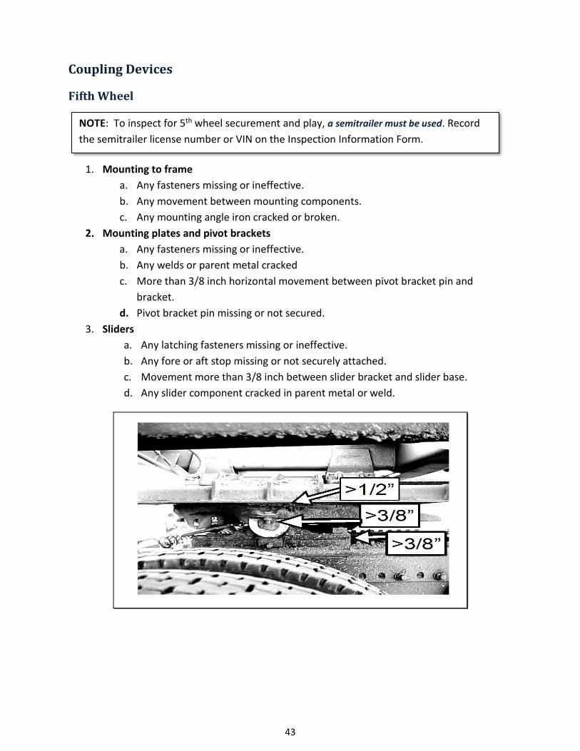
43
Coupling Devices
Fifth Wheel
NOTE: To inspect for 5th wheel securement and play, a semitrailer must be used. Record the semitrailer license number or VIN on the Inspection Information Form.
1. Mounting to frame a. Any fasteners missing or ineffective. b. Any movement between mounting components. c. Any mounting angle iron cracked or broken.
2. Mounting plates and pivot brackets a. Any fasteners missing or ineffective. b. Any welds or parent metal cracked c. More than 3/8 inch horizontal movement between pivot bracket pin and
bracket. d. Pivot bracket pin missing or not secured.
3. Sliders a. Any latching fasteners missing or ineffective. b. Any fore or aft stop missing or not securely attached. c. Movement more than 3/8 inch between slider bracket and slider base. d. Any slider component cracked in parent metal or weld.

44
4. Lower Coupler a. Horizontal movement between the upper and lower fifth wheel halves exceeds
½ inch. b. Operating handle not in closed or locked position. c. King pin not properly engaged. d. Separation between upper and lower coupler allowing light to show through
from side to side. e. Cracks in the fifth wheel plate. f. Exceptions: Cracks in fifth wheel approach ramps and casting shrinkage cracks in
the ribs of the body of a cast fifth wheel. g. Locking mechanism parts missing, broken, or deformed to the extent the king pin
is not securely held. h. A crack, or a gap caused by corrosion, that is 1/8 inch or more in width. (rust
jacking) 5. Upper Coupler
Must have the minimum number of bolts per side based on the size and grade of bolt used.

45
Pintle Hook
1. Mounting to frame a. Any missing or ineffective fasteners (a fastener is not considered missing if there
is an empty hole in the device but no corresponding hole in the frame or vice versa).
b. Mounting surface cracks extending from point of attachment (e.g., cracks in the frame at mounting bolt holes).
c. Loose mounting d. Frame cross member providing pintle hook attachment cracked.
2. Integrity a. Cracks anywhere in pintle hook assembly. b. Any welded repairs to the pintle hook. c. Any part of the horn section reduced by more than 20 percent. d. Latch insecure.
Drawbar/Tow bar Eye
1. Mounting a. Any cracks in attachment welds. b. Any missing or ineffective fasteners
2. Integrity a. Any cracks. b. Any part of the eye reduced by more than 20 percent. c. No welded repairs.
Drawbar/Tow bar Tongue
1. Slider (power or manual) a. Ineffective latching mechanism. b. Missing or ineffective stop. c. Movement of more than ¼ inch between slider and housing. d. Any leaking, air or hydraulic cylinders, hoses, or chambers (other than slight oil
weeping normal with hydraulic seals). 2. Integrity
a. Any cracks. b. Movement of ¼ inch between subframe and drawbar at point of attachment.
46
Ball hitches
Inspect for the following items: 1. Ball mount not bent, cracked, worn 2. Ball not loose 3. Hitch assembly has proper weight rating for trailer 4. Ball mount and receiver size match 5. Positive locking mechanism on coupler 6. Receiver not bent, cracked, worn
Safety Devices/Safety Chain Requirements
Every trailer, including gooseneck style, must be equipped with safety devices, unless it is equipped with a kingpin and fifth wheel type coupler.
Safety Devices
1. Missing. 2. Unattached. 3. Incapable of secure attachment.
Chains and Hooks
1. Worn to the extent of measurable reduction in link cross section. 2. Improper repairs including welding, wire, small bolts, rope and tape.
Cable
1. Kinked or broken cable strands. 2. Improper clamps or clamping.
Safety Device Requirements
1. Cannot be attached to any part of the hitch. 2. Only enough slack in safety device as needed to make turns. 3. The ultimate breaking strength of safety devices must be equal to the weight of
the trailer and load.

47
Working Load Limits (WLL)
Ultimate Breaking Strength = 3(WLL)
To determine the ultimate (breaking) strength for safety chains or cables, multiply the working load limit (WLL) by three.
Example: To determine the ultimate 3/4 strength for two ¼” Grade 4 chains, look 7/8 up the WLL in the table and calculate as 1 follows:
¼” Grade 4 WLL 2,600 x 3 = 7,800 pounds ultimate breaking strength Multiply by number of devices
Additional Requirements:
• Must be installed in a manner that will prevent the draw-bar from contacting the roadway if it becomes disconnected from the towing unit.
• Attachment to the towed vehicle (two safety devices) one on each side and equal distance of the center line of the towing vehicle. (Bridle arrangement, single attachment point) must be attached on the center line of the towing vehicle.
• If trailer is equipped with a pivoting draw-bar, the safety chain or cable must be attached to the trailer frame or axle as far apart as practicable and must be one continuous length to attachment point of towing vehicle.
Size (inch)
Working Load Limit, Chain (pounds)
Grade 30 Proof Coil
Grade 43 High Test
Grade 70 Transport
Grade 80 Alloy
Grade 100 Alloy
1/4 1,300 2,600 3,150 3,500 4,300 5/16 1,900 3,900 4,700 4,500 5,700 3/8 2,650 5,400 6,600 7,100 8,800
7/16 3,700 7,200 8,750 1/2 4,500 9,200 11,300 12,000 15,000 5/8 6,900 13,000 15,800 18,100 22,600
Chain Marking Examples:
Example 1 3 4 7 8 10
Example 2 30 43 70 80 100 Example 3 300 430 700 800 1000
Working Load Limit, Cable Diameter (inch) WLL (pounds)
1/4 1,400 5/16 2,100 3/8 3,000
7/16 4,100 1/2 5,300 5/8 8,300
10,900 16,100 20,900
NOTE: Quick links that are fully engaged and marked with a manufacturer’s minimum breaking strength/force (MBS/MBF) rating on the link, that is equal to or greater than the GVW of the trailer(s) are acceptable for use in a safety device.

48
Figure 1 – Inspect all links for gouges, chips, cuts, and abrasions
Figure 2 – Inspect all links for wear at bearing surfaces
Figure 3 – Never twist or knot a chain Figure 4 – Look for signs of chain stretch
Figure 5 – Inspect all links for bends, twists, and damage
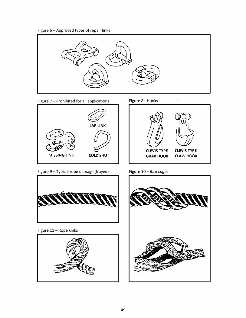
49
Figure 6 – Approved types of repair links
Figure 7 – Prohibited for all applications Figure 8 - Hooks
Figure 9 – Typical rope damage (frayed) Figure 10 – Bird cages
Figure 11 – Rope kinks

50
Saddle Mounts
Method of attachment
a. Any missing or ineffective fasteners. b. Loose mountings. c. Any cracks or breaks in a stress or load bearing member. d. Horizontal movement between upper and lower saddle mount halves exceeds ¼
inch.
Exhaust System
1. Any exhaust system determined to be leaking at a point forward of or directly below the driver/sleeper compartment.
2. A bus exhaust system leaking or discharging to the atmosphere. a. Gasoline powered – excess of 6 inches forward of the rearmost part of the bus. b. Other than gasoline powered – in excess of 15 inches forward of the rearmost
part of the bus. c. Other than gasoline powered – forward of a door or window designed to be
opened (except: emergency exits).
3. No part of the exhaust system of any motor vehicle shall be so located as would likely to result in burning, charring, or damaging the electrical wiring, the fuel supply, or any combustible part of the motor vehicle.
Fuel System
This includes fuel systems on refrigeration units, compressors, generators, or any other type of equipment attached to or carried upon a commercial motor vehicle.
1. A fuel system with a visible leak at any point. 2. A fuel tank filler cap missing. 3. A fuel tank not securely attached to the motor vehicle by reason of loose, broken or
missing mounting bolts or brackets (some fuel tanks use springs or rubber bushings to permit movement).

51
Lighting Devices
All required lighting devices and reflectors shall be operable.
All required lamps are listed in 393.11 Table 1 (Lighting Chart) and must be capable of operation at all times! (393.9)

52
Item on the Vehicle Quantity Color Location Position Height above the road surface
measured from the center of the lamp at curb weight
Vehicles for which the devices
are required.
Headlamps 2 White Front On the front at the same height, with an equal number at each side of the vertical center line as far apart as practicable.
Not less than 22 inches nor more than 54 inches.
A, B, C
Turn signal (front). See footnotes #2 and 12.
2 Amber At or near the front.
One on each side of the vertical centerline at the same height and as far apart as practicable.
Not less than 15 inches nor more than 83 inches.
A, B, C
Identification lamps (front). See footnote #1.
3 Amber Front As close as practicable to the top of the vehicle, at the same height, and as close as practicable to the vertical centerline of the vehicle (or the vertical centerline of the cab where different from the centerline of the vehicle) with lamp centers spaced not less than 152 mm (6 inches) or more than 305 mm (12 inches) apart. Alternatively, the front lamps may be located as close as practicable to the top of the cab.
All three of the same level as close as practicable to the top of the motor vehicle.
B, C
Tail lamps. See footnotes #5 and 11.
2 Red Rear One lamp on each side of the vertical centerline at the same height and as far apart as practicable.
Both on the same level between 15 inches and 72 inches.
A, B, C, D, E, F, G, H
Stop lamps. See footnotes #5 and 13.
2 Red Rear One lamp on each side of the vertical centerline at the same height and as far apart as practicable.
Both on the same level between 15 inches and 72 inches.
A, B, C, D, E, F, G
Clearance lamps. See footnotes #8, 9, 10, 15 & 17.
2 Amber One on each side of the front of the vehicle.
One on each side of the vertical centerline to indicate overall width.
Both on the same level as high as practicable.
B, C, D, G, H
2 Red One on each side of the rear of the vehicle.
One on each side of the vertical centerline to indicate overall width.
Both on the same level as high as practicable.
B, D, G, H
Reflex reflector, intermediate (side).
2 Amber One on each side. At or near the midpoint between the front and rear side marker lamps, if the length of the vehicle is more than 9,144 mm (30 feet).
Between 15 inches and 60 inches.
A, B, D, F, G
Reflex reflector (rear). See footnotes #5, 6, and 8.
2 Red Rear One on each side of the vertical centerline, as far apart as practicable and at the same height.
Both on the same level, between 15 inches and 60 inches.
A, B, C, D, E, F, G
Reflex reflector (rear side).
2 Red One on each side (rear).
As far to the rear as practicable. Both on the same level, between 15 inches and 60 inches.
A, B, D, F, G
Reflex reflector (front side). See footnote #16.
2 Amber One on each side (front).
As far to the front as practicable. Between 15 inches and 60 inches.
A, B, C, D, F, G
License plate lamp (rear). See footnote #11.
1 White At rear license plate to illuminate the plate from the top or sides.
No requirements. A, B, C, D, F, G
Side marker lamp (front). See footnote #16.
2 Amber One on each side. As far to the front as practicable. Not less than 15 inches. A, B, C, D, F
Side marker lamp intermediate.
2 Amber One on each side. At or near the midpoint between the front and rear side marker lamps, if the length of the vehicle is more than 9,144 mm (30 feet).
Not less than 15 inches. A, B, D, F, G
Side marker lamp (rear). See footnotes #4 and 8.
2 Red One on each side. As far to the rear as practicable. Not less than 15 inches, and on the rear of trailers not more than 60 inches.
A, B, D, F, G
Turn signal (rear). See footnotes #5 and 12.
2 Amber or red
Rear One lamp on each side of the vertical centerline as far apart as practicable.
Both on the same level, between 15 inches and 83 inches.
A, B, C, D, E, F, G
Identification lamp (rear). See footnotes #3, 7, and 15.
3 Red Rear One as close as practicable to the vertical centerline. One on each side with lamp centers spaced not less than 152 mm (6 inches) or more than 305 mm (12 inches) apart.
All three on the same level as close as practicable to the top of the vehicle.
B, D, G
Vehicular hazard warning signal flasher lamps. See footnotes #5 and 12.
2 Amber Front One lamp on each side of the vertical centerline, as far apart as practicable.
Both on the same level, between 15 inches and 83 inches.
A, B, C
2 Amber or red
Rear One lamp on each side of the vertical centerline, as far apart as practicable.
Both on the same level, between 15 inches and 83 inches.
A, B, C, D, E, F, G
Backup lamp. See footnote #14.
1 or 2 White Rear Rear No Requirement A, B, C
Parking lamp. 2 Amber or
white
Front One lamp on each side of the vertical centerline, as far apart as practicable.
Both on the same level, between 15 inches and 83 inches.
A

53
Legend for types of commercial motor vehicles shown in the last column of the Lighting Chart.
A. Buses and trucks less than 80 inches in overall width. B. Buses and trucks 80 inches or more in overall width. C. Truck tractors. D. Semitrailers and full trailers 80 inches or more in
overall width except converter dollies.
E. Converter dolly. F. Semitrailers and full trailers less than 80 inches in
overall width. G. Pole trailers. H. Projecting loads.
Note: Lamps and reflectors may be combined as permitted by §393.22 and S5.4 of 49 CFR 471.108, Equipment combinations. Footnote-1 Identification lamps may be mounted on the vertical centerline of the cab where different from the centerline of the vehicle, except where the cab is not more than 42 inches wide at the front roofline, then a single lamp at the center of the cab shall be deemed to comply with the requirements for identification lamps. No part of the identification lamps or their mountings may extend below the top of the vehicle windshield. Footnote-2 Unless the turn signals on the front are so constructed (double-faced) and located as to visible to passing drivers, two turn signals are required on the rear of the truck tractor, one at each side as far apart as practicable. Footnote-3 The identification lamps need not be visible or lighted if obscured by a vehicle in the same combination. Footnote-4 Any semitrailer or full trailer manufactured on or after March 1, 1979, shall be equipped with rear side-marker lamps at a height of not less than 381 mm (15 inches), and on the rear of trailers not more than 1,524 mm (60 inches) above the road surface, as measured from the center of the lamp on the vehicle at curb weight. Footnote-5 Each converter dolly, when towed singly by another vehicle and not as part of a full trailer, shall be equipped with one stop lamp, one tail lamp, and two reflectors (one on each side of the vertical centerline, as far apart as practicable) on the rear. Each converter dolly shall be equipped with rear turn signals and vehicular hazard warning signal flasher lamps when towed singly by another vehicle and not as part of a full trailer, if the converter dolly obscures the turn signals at the rear of the towing vehicle. Footnote-6 Pole Trailers shall be equipped with two reflex reflectors on the rear, one on each side of the vertical centerline as far apart as practicable, to indicate the extreme width of the trailer. Footnote-7 Pole trailers, when towed by motor vehicles with rear identification lamps meeting the requirements of §393.11 and mounted at a height greater than the load being transported on the pole trailer, are not required to have rear identification lamps. Footnote-8 Pole trailers shall have on the rearmost support for the load: (1) two front clearance lamps, one on each side of the vehicle, both on the same level and as high as practicable to indicate the overall width of the pole trailer; (2) two rear clearance lamps, one on each side of the vehicle, both on the same level, not less than 375 mm (15 inches) above the road surface to indicate maximum width of the pole trailer and (5) one red reflector on each side of the rearmost support for the load. Lamps and reflectors may be combined as allowed in §393.22. Footnote-9 Any motor vehicle transporting a load which extends more than 102 mm (4 inches) beyond the overall width of the motor vehicle shall be equipped with the following lamps in addition to other required lamps when operated during the hours when headlamps are required to be used. (1) The foremost edge of that portion of the load which projects beyond the side of the vehicle shall be marked (at its outermost extremity) with an amber lamp visible from the front and side. (2) The rearmost edge of that portion of the load which projects beyond the side of the vehicle shall be marked (at its outermost extremity) with a red lamp visible from the rear and side. (3) If the projecting load does not measure more than 914 mm (3 feet) from front to rear, it shall be marked with an amber lamp visible from the front, both sides, and rear, except that if the projection is loaded at or near the rear it shall be marked by a read lamp visible from front side, and rear. Footnote-10 Projections beyond rear of motor vehicles. Motor vehicles transporting loads which extend more than 1,219 mm (4 feet) beyond the rear of the motor vehicle, or which have tailboards or tailgates extending more than 1,219 mm (4 feet) beyond the body, shall have these projections marked as follows when the vehicle is operated during the hours when headlamps are required to be used: (1) On each side of the projecting load, one red side marker lamp, visible from the side, located so as to indicate maximum overhang. (2) On the rear of the projecting load, two red lamps, visible from the rear, one at each side; and two red reflectors visible from the rear, one at each side, located so as to indicate maximum width. Footnote-11 To be illuminated when tractor headlamps are illuminated. No rear license plate lamp is required on vehicles that do display a rear license plate. (FR July 22, 2016) Footnote-12 Every bus, truck, and truck tractor shall be equipped with a signaling system that, in addition to signaling turning movements, shall have a switch or combination of switches that will cause the two front turn signals and the two rear signals to flash simultaneously as a vehicular traffic signal warning, required by §392.22(a). The system shall be capable of flashing simultaneously with the ignition of the vehicle on or off. Footnote-13 To be actuated upon application of service brakes. Footnote-14 Backup lamp required to operate when bus, truck, or truck tractor is in reverse. Footnote-15 (1) For the purposes of Section 393.11, the term “overall width” refers to the nominal design dimension of the widest part of the vehicle, exclusive of the signal lamps, marker lamps, outside rearview mirrors, flexible fender extensions, and mud flaps. (2) Clearance lamps may be mounted at a location other than on the front and rear if necessary to indicate the overall width of a vehicle, or for protection from damage during normal operation of the vehicle. (3) On a trailer, the front clearance lamps may be mounted at a height below the extreme height if mounting at the extreme height results in the lamps failing to mark the overall width of the trailer. (4) On the truck tractor, clearance lamps mounted on the cab may be located to indicate the width of the cab, rather than the width of the vehicle. (5) When the rear identification lamps are mounted at the extreme height of a vehicle, rear clearance lamps are not required to be located as close as practicable to the top of the vehicle. Footnote-16 A trailer subject to this part that is less than 1829 mm (6 feet) in overall length, including the trailer tongue, need not be equipped with front side marker lamps and front side reflex reflectors. Footnote-17 A boat trailer subject to this part whose overall width is 2032 mm (80 inches) or more need not be equipped with both front and rear clearance lamps provided an amber (front) and red (rear) clearance lamp is located at or near the midpoint on each side so as to indicate its extreme width.

54
Warning flags on projecting loads
1. Any commercial motor vehicle transporting a load which extends beyond the sides by more than 102 mm (4 inches) or more than 1219 mm (4 feet) beyond the rear must have the extremities of the load marked with red or orange fluorescent warning flags. Each warning flag must be at least 457 mm (18 inches) square
2. Position of Flags. There must be a single flag at the extreme rear if the projecting load is two feet wide or less. Two warning flags are required if the projecting load is wider than two feet. Flags must be located to indicate maximum width of loads which extend beyond the sides and/or rear of the vehicle.
Permitted Combinations Two or more lighting devices may be combined optically if:
1. each device conforms to the rules 2. not inconsistent with rules or impairs effectiveness
Prohibited Combinations Lighting devices that cannot be combined:
1. headlamp and turn signal 2. stop light and turn signal, unless turn signal has priority 3. clearance lamps, identification lamps, and tail lamps must be separate lamps.
(cannot be combined optically with each other) Visibility. Each lamp shall be located so that it meets the visibility requirements specified by FMVSS No. 108 in effect at the time of manufacture of the vehicle.
FMVSS 108 S5.1.3 No additional lamp, reflective device or other motor vehicle equipment shall be installed that impairs the effectiveness of lighting equipment required by FMVSS 108.

55
Conspicuity Treatment Requirements
TRAILERS: All trailers and semitrailers, regardless of their date of manufacture, which have an overall width of 80 inches or more and a gross vehicle weight rating of 10,001 pounds or more, except trailers that are manufactured exclusively for use as offices or dwellings, pole trailers, and trailers transported in a driveaway-towaway operation, must be equipped with retro-reflective sheeting or an array of reflex reflectors that meet the requirements of the Federal Motor Vehicle Safety Standards.
Tape must be either the full length of the vehicle, or you may space the tape. If you choose to space the tape you must have one piece at the very front and one piece at the extreme rear, and the rest of the tape must be evenly spaced between with at least 50% of the side covered. The tape on the rear must show the full width of the vehicle. Trailers manufactured on or after December 1, 1993, must also have conspicuity marking covering the full width of the horizontal member of the rear impact guard.
TRUCK-TRACTORS MANUFACTURED ON OR AFTER 7/1/1997 must have a red and white strip on each wheel flap bracket, and two L shaped white strips on each side of the rear, as close to the top of the body and as far apart as practicable.
If the truck-tractor is not equipped with wheel flap brackets or similar devices, the conspicuity material may be affixed to a suitable location on the rear of the cab or bulkhead and visible above the rear tires of the truck-tractor.
NOTE: Conspicuity tape is not required on any other vehicles.
NOTE: Conspicuity tape may be used in lieu of required reflectors on trailers.

56
Marking of Lenses and Light Fixtures
A = Reflector
SAE S = Stop lamp
SAE A1 or SAE I = Turn signal
SAE or SAE P = Clearance, side marker, identification and projecting load lamps. Combination lamps must be marked ‘SAE’ plus the letter indicating what the lamp is. For example: SAE A1 = Turn signal and reflector
VISABILITY – all required lighting devices must be visible, between 50 feet and 500 feet when lights are required.
MOUNTING – all lights shall be permanently and securely mounted in a workman like manner, on a permanent part of the vehicle.
WIRING – must be grouped together, when possible, and protected by nonconductive tape, braid, or other covering. And be properly supported against, chaffing.
NOTE: SAE PC, PC2, or PC3 marking on lenses – may be used as front or rear clearance and side marker lamps on trailers. These lamps may be mounted on the side of a trailer near the front and/or near the rear. They must be visible from the front and/or rear.

57

58

59
LEGEND FOR FIGURES 1 THROUGH 7 - 49 CFR 393.11 TRUCK & BUS VEHICLE ILLUSTRATIONS
(DOES NOT APPLY TO FIGURES 8 THROUGH 17 FOR TRAILERS)
Area Equipment
1
Headlamps – Lower beam Headlamps – Upper beam Parking Lamps – Attention: Required only on vehicles less than 2032 mm wide Front Turn Signal/Hazard Lamps
2 Front Clearance Lamps – Attention: Required for vehicles 2032 mm wide or wider 3 Front Identification Lamps (ID)
4a Front Side Marker Lamps 4b Front Side Reflex Reflectors 5a Rear Side Marker Lamps - Not required on truck-tractors 5b Rear Side Reflex Reflectors - Not required on truck-tractors
6 Rear Clearance Lamps Attention: Required for vehicles 2032 mm wide or wider, but not required on truck-tractors
7 Rear Identification Lamps Attention: Required for vehicles 2032 mm wide or wider, but not required on truck-tractors
8
Tail Lamps Stop Lamps Rear Turn Signal/Hazard Lamps Rear Reflex Reflectors
9 Backup Lamp 10 License Plate Lamp (when required)
11 Center High Mounted Stop Lamp Attention: Required for vehicles less than 2032 mm wideand 4536 kg
ADDITIONAL EQUIPMENT FOR SPECIFIC TRUCKS AND BUS VEHICLES
Area Equipment 12a Intermediate Side Marker 12b Intermediate Side Reflectors
TRUCK TRACTORS Area Conspicuity Treatment
13 Upper Body Markings 14 Rear Marking

60

61

62

63
LEGEND FOR FIGURES 8 THROUGH 17 – 49 CFR 393.11 TRAILER ILLUSTRATIONS
(Does not apply to Figures 1 through 7 for Trucks and Buses)
Area Equipment
1
Tail Lamps
Stop Lamps
Rear Turn Signal Lamps
Rear Reflex Reflectors
2 License Plate Lamp(s)
3 Rear Side Marker Lamps
Rear Side Reflex Reflectors
4a Front Side Marker Lamps
4b Front Side Reflex Reflectors
ADDITIONAL EQUIPMENT FOR TRAILERS EXCEEDING THE FOLLOWING PARAMETERS: LENGTH 9.1 M (30 FT.) OR LONGER
Area Equipment 5a Intermediate Side Marker Lamps
5b Intermediate Side Reflex Reflectors
WIDTH 2.032 M (80 IN.) OR WIDER Area Equipment
6 Rear Clearance Lamps
7 Rear Identification Lamps
8 Front Clearance Lamps
WIDTH 2.032 M (80 IN.) OR WIDER AND GVWR 4,536 KG (10,000 LB.) OR MORE Area Conspicuity Treatment
9 Rear Upper Body Marking
10 Bumper Bar Marking
11 Rear Lower Body Marking
12 Side Marking
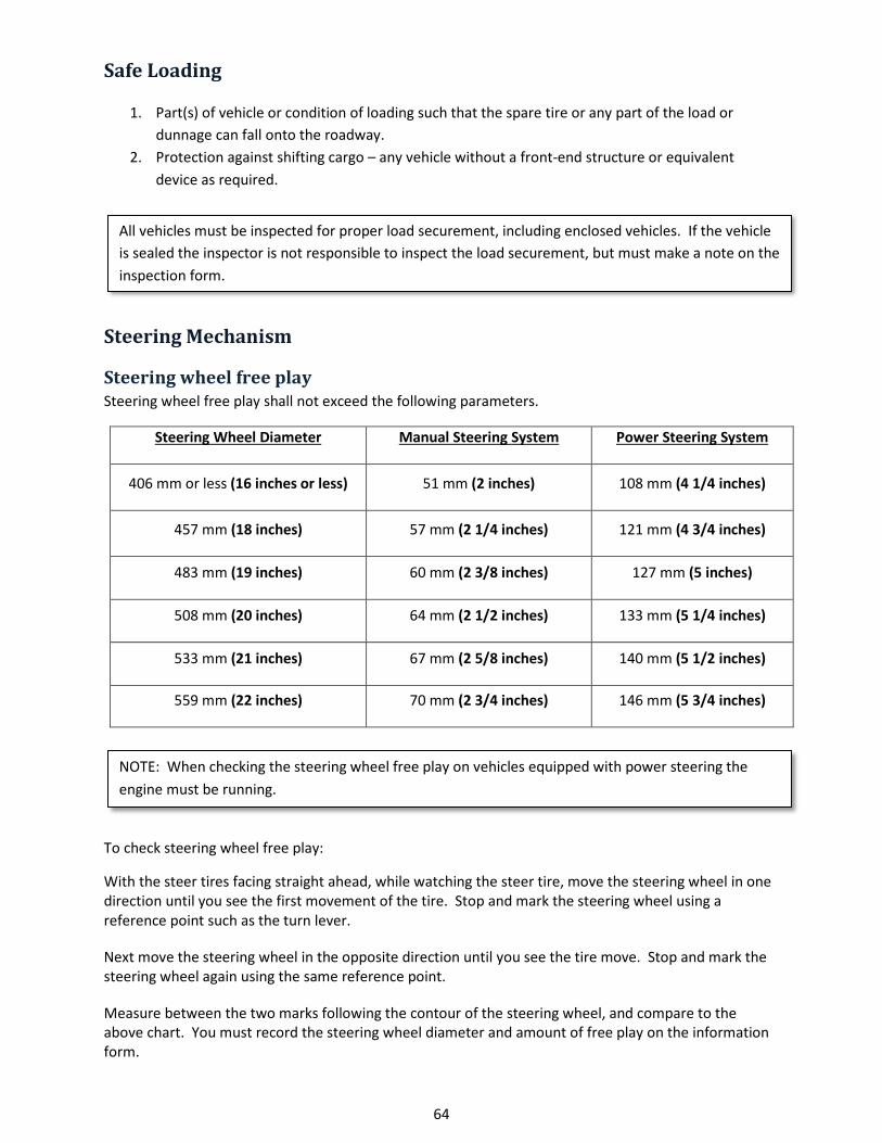
64
Safe Loading
1. Part(s) of vehicle or condition of loading such that the spare tire or any part of the load or dunnage can fall onto the roadway.
2. Protection against shifting cargo – any vehicle without a front-end structure or equivalent device as required.
All vehicles must be inspected for proper load securement, including enclosed vehicles. If the vehicle is sealed the inspector is not responsible to inspect the load securement, but must make a note on the inspection form.
Steering Mechanism
Steering wheel free play Steering wheel free play shall not exceed the following parameters.
Steering Wheel Diameter Manual Steering System Power Steering System
406 mm or less (16 inches or less) 51 mm (2 inches) 108 mm (4 1/4 inches)
457 mm (18 inches) 57 mm (2 1/4 inches) 121 mm (4 3/4 inches)
483 mm (19 inches) 60 mm (2 3/8 inches) 127 mm (5 inches)
508 mm (20 inches) 64 mm (2 1/2 inches) 133 mm (5 1/4 inches)
533 mm (21 inches) 67 mm (2 5/8 inches) 140 mm (5 1/2 inches)
559 mm (22 inches) 70 mm (2 3/4 inches) 146 mm (5 3/4 inches)
NOTE: When checking the steering wheel free play on vehicles equipped with power steering the engine must be running.
To check steering wheel free play:
With the steer tires facing straight ahead, while watching the steer tire, move the steering wheel in one direction until you see the first movement of the tire. Stop and mark the steering wheel using a reference point such as the turn lever.
Next move the steering wheel in the opposite direction until you see the tire move. Stop and mark the steering wheel again using the same reference point.
Measure between the two marks following the contour of the steering wheel, and compare to the above chart. You must record the steering wheel diameter and amount of free play on the information form.

65
Steering Column
1. Any absence or looseness of U-bolt(s) or positioning part(s). 2. Worn, faulty or obviously repaired welded universal joint(s). 3. Steering wheel not properly secured, or
• Telescopic steering column does not lock into position, or • Tilt steering column does not lock in at least one position.
Front Axle Beam and All Other Components
1. Any crack(s). 2. Any obviously welded repair(s).
Steering Gear Box
1. Any mounting bolt(s) loose or missing. 2. Any crack(s) in gear box or mounting brackets.

66
Pitman Arm
Any looseness of the pitman arm on the steering gear output shaft.
Power Steering
Auxiliary power assist cylinder loose.
Ball and Socket Joints
1. Any movement under steering load of a stud nut. 2. Any motion, other than rotational, between any linkage member and its attachment point of
more than ¼ inch. (more than 1/8 inch measured with hand pressure)
Tie Rods and Drag Links
1. Loose clamp(s) or clamp bolt(s) on tie rods or drag links. 2. Any looseness in any threaded joint. 3. Nut(s) loose or missing on tie rods, pitman arm, drag link, steering arm or tie rod arm.
Steering System
NOTE: This includes tire touching frame or any steering parts, belts slipping, weak power steering pump, or low fluid.
Any modification or other condition that interferes with free movement of any steering component.
Vehicles equipped with hydraulic brakes that use the power steering pump as the source of power when engine is running should be tested as follows:
• Have engine running at idle • Steer tires straight • Make full brake application, and hold • Grab steering wheel at the 2 o’clock position and rock to the 10 o’clock position • If you discover any interference, binding, or you cannot move the steering wheel through
the above mentioned arc the vehicle will fail the inspection.

67
Suspension
1. Any U-bolt(s), spring hanger(s), or other axle positioning part(s) cracked, broken, loose or missing resulting in shifting of an axle from its normal position.
After a turn, lateral axle displacement is normal with some suspensions. Forward or rearward operation in a straight line will cause the axle to return to alignment.
2. Spring Assembly a. Any leaves in a leaf spring assembly broken or missing. b. Any broken main leaf in a leaf spring assembly. (Includes assembly with more
than one main spring) c. Coil spring broken. d. Rubber spring missing. e. One or more leaves displaced in a manner that could result in contact with a tire,
rim, brake drum or frame. f. Broken torsion bar spring in a torsion bar suspension. g. Deflated air suspension, i.e., system failure, leak etc.
(Leakage shall not be greater than 3 psi in a 5-minute time period)
3. Torque, Radius or Tracking Components. a. Any part of a torque, radius or tracking component assembly or any part used for
attaching the same to the vehicle frame or axle that is cracked, loose, broken or missing.
b. Any part of a suspension connecting rod or tracking component assembly (including spring leaves used as a suspension connecting rod) equipped with rubber bushings is missing the bushing or the bushing is worn to the extent that the component can be moved by hand along the axis of the component.

68

69
Frame
1. Frame Members – Including frame cross members a. Any cracked, broken, loose or sagging frame member b. Any loose or missing fasteners including fasteners attaching functional
component such as engine, transmission, steering gear, suspension, body parts, and fifth wheel.
2. Tire and Wheel Clearance Any condition including loading, that causes the body or frame to be in contact with a tire or any part of the wheel assemblies.
3. Adjustable Axle Assemblies (sliding subframes) Adjustable axle assembly with locking pins missing or not engaged.
Tires
Any tire on any steering axle of a power unit 1. With less than 4/32-inch tread when measured at any point on a major tread groove.
NOTE: Do not measure tread depth at the wear bars.
NOTE: Tire tread depth must be recorded on the Vehicle Information Form.
2. Has body ply or belt material exposed through the tread or sidewall. 3. Has any tread or sidewall separation. 4. Has a cut where the ply or belt material is exposed. 5. Labeled “Not for Highway Use” or displaying marking which would exclude use on
steering axle. 6. A tube-type radial tire without radial tube stem markings. These markings include a red
band around the tube stem, the word “radial” embossed in metal stems, or the word “radial” molded in rubber stems.
7. Mixing bias and radial tires on the same axle. 8. Tire flap protrudes through valve slot in rim and touches stem. 9. Regrooved tire except motor vehicles used solely in urban or suburban service (see
exception in 393.75(e)) 10. Boot, blowout patch or other ply repair.

70
11. Weight carried exceeds tire load limit. This includes overloaded tire resulting from low air pressure.
12. Tire is flat (50% or less of the cold rated pressure) or has noticeable leak (e.g., can be heard or felt).
NOTE: Tire pressure must be recorded on the Vehicle Information Form.
13. Any bus equipped with recapped or retreaded tire(s). 14. So mounted or inflated that it comes in contact with any part of the vehicle.
All tires other than on the steering axle of a power unit 1. Weight carried exceeds tire load limit. (This includes overloaded tire resulting from low
air pressure). 2. Tire is flat (50% or less of the cold rated pressure) or has a noticeable leak (e.g., can be
heard or felt) 3. Has body ply or belt material exposed through the tread or sidewall. 4. Has any tread or sidewall separation. 5. Has a cut where ply or belt material is exposed. 6. So mounted or inflated that it comes in contact with any part of the vehicle. (This
includes a tire that contacts its mate.) 7. Is marked “Not for Highway Use” or otherwise marked and having like meaning. 8. With less than 2/32-inch tread when measured at any point on a major tread groove.
NOTE: Tire tread depth must be recorded on the Vehicle Information Form.
Tires on all axles Installation of speed-restricted tires unless specifically designated by motor carrier.
Wheels and Rims
1. Lock or Side Ring - bent, broken, cracked improperly seated, sprung or mismatched ring(s)
2. Wheels and Rim - cracked or broken or has elongated bolt holes. 3. Fasteners (both spoke and disc wheels) - any loose, missing, broken, cracked, stripped or
otherwise ineffective fasteners. 4. Welds
a. Any cracks in welds attaching disc wheel disc to rim. b. Has crack in welds attaching tubeless demountable rim to adapter. c. Any welded repair on aluminum wheel(s) d. Any welded repair other than disc to rim attachment on steel disc wheel(s).

71
Windshield Glazing
Windshield Condition
With the exception of the conditions listed below, each windshield shall be free of discoloration or damage in the area extending upward from the height of the top of the steering wheel, excluding a 2-inch border at the top of the windshield and extending from a 1-inch border at each side of the windshield or windshield panel.
Exceptions:
1. Coloring or tinting which meets the requirements of this section; 2. Any crack that is not intersected by any other cracks; 3. Any damaged area which can be covered by a disc 19 mm (¾ inch) in diameter if not
closer than 76 mm (3 inches) to any other similarly damaged area.
Coloring or Tinting of Windshields and Windows.
Coloring or tinting of windshields and the windows to the immediate right and left of the driver is allowed, provided the parallel luminous transmittance through the colored or tinted glazing is not less than 70 percent of the light at normal incidence in those portions of the windshield or windows which are marked as having a parallel luminous transmittance of not less than 70 percent. The transmittance restriction does not apply to other windows on the commercial motor vehicle.
Prohibition on Obstructions to the Driver’s Field of View
1. Devices mounted at the top of the windshield. Antennas, transponders, and similar devices must not be mounted more than 6 inches below the upper edge of the windshield. These devices must be located outside the area swept by the windshield wipers, and outside the driver’s sight lines to the road and highway signs and signals.
2. Decals and Stickers Mounted on the Windshield. Commercial Vehicle Safety Alliance (CVSA) inspection decals, and stickers and/or decals required under Federal or State laws may be placed at the bottom or sides of the windshield provided such decals or stickers do not extend more than 4 ½ inches from the bottom of the windshield and are located outside the area swept by the windshield wipers, and outside the driver’s sight lines to the road and highway signs or signals.

72
Windshield Wipers, Washers, and Defrosters
Any power unit that has an inoperative wiper, or missing or damaged parts that render it ineffective.
1. Vehicles manufactured on or after December 25, 1968.
Each bus, truck, and truck-tractor manufactured on or after December 25, 1968, must have a windshield wiping system that meets the requirements of FMVSS No. 104 (S4.1) in effect on the date of requirements of FMVSS No. 104 (S4.2.2) in effect on the date of manufacture.
2. Vehicles manufactured between June 30, 1953, and December 24, 1968.
Each truck, truck-tractor, and bus manufactured between June 30, 1953, and December 24, 1968, shall be equipped with a power-driven windshield wiping system with at least two wiper blades, one on each side of the centerline of the windshield. Motor vehicles which depend upon vacuum to operate the windshield wipers, shall have the wiper system constructed and maintained such pressure that the performance of the wipers will not be adversely affected by a change in the intake manifold.
Any power unit that has a defective, ineffective or no defroster device
1. Vehicles manufactured on or after December 25, 1968.
Each bus, truck, and truck-tractor manufactured on or after December 25, 1968 must have a windshield defrosting and defogging system that meets the requirements of FMVSS No. 103 in effect on the date of manufacture.
2. Vehicles manufactured before December 25, 1968.
Each bus, truck, and truck-tractor manufactured before December 25, 1968 shall be equipped with a means for preventing the accumulation of ice, snow, frost, or condensation that could obstruct the driver’s view through the windshield while the vehicle is being driven.
Motorcoach Seats
Any passenger seat that is not securely fastened to the vehicle structure.
Any foldup aisle seat that does not automatically fold and leave a clear aisle when the seat is not occupied.

73
Additional Inspection Items
Rear Vision Mirrors
Every bus, truck and truck-tractor shall be equipped with two rear-vision mirrors, one at each side, firmly attached to the outside of the motor vehicle, and so located as to reflect to the driver a view of the highway to the rear, along both sides of the vehicle. All such regulated rear-vision mirrors and their replacements shall meet, as a minimum, the requirements of FMVSS No. 111 (49 CFR §571.111) in force at the time the vehicle was manufactured.
Horn
Every bus, truck, truck-tractor, and every driven motor vehicle in driveaway-towaway operations shall be equipped with a horn and actuating elements which shall be in such condition as to give an adequate and reliable warning signal.
Fire Extinguisher
Each truck, truck-tractor, and bus (except those towed in driveaway-towaway operations) must be equipped as follows:
1. A power unit that is used to transport hazardous materials in a quantity that requires placarding (See 49 CFR §177.823) must be equipped with a fire extinguisher having an Underwriters’ Laboratories rating of 10 B:C or more.
2. A power unit that is not used to transport hazardous materials must be equipped with either: A fire extinguisher having an Underwriters’ Laboratories rating of 5 B:C or more; or two fire extinguishers, each of which has an Underwriters’ Laboratories rating of 4 B:C or more.
3. Labeling and marking. Each fire extinguisher required by this section must be labeled or marked by the manufacturer with its Underwriters’ Laboratories rating.
4. Visual Indicators. The fire extinguisher must be designed, constructed, and maintained to permit visual determination of whether it is fully charged.
5. Condition, location, and mounting. The fire extinguisher(s) must be filled and located so that it is readily accessible for use. The extinguisher(s) must be securely mounted to prevent sliding, rolling, or vertical movement relative to the motor vehicle.
Warning Devices for Stopped Vehicles
Except as provided in paragraph (4) of this section, one of the following options must be used:
1. Three bidirectional emergency reflective triangles that conform to the requirements of Federal Motor Vehicle Safety Standard No. 125, §571.125 of this title; or
2. At least 6 fusees or 3 liquid-burning flares. The vehicle must have as many additional fusees or liquid-burning flares as are necessary to satisfy the requirements of §392.22.

74
3. Other warning devices may be used in addition to, but not in lieu of, the required warning devices, provided those warning devices do not decrease the effectiveness of the required warning devices.
4. Restrictions on the use of flame producing devices. Liquid burning flares, fusees, oil lanterns or any signal produced by a flame shall not be carried on any commercial motor vehicle transporting Division 1.1, 1.2, 1.3 (explosive) hazardous materials; any cargo tank motor vehicle used for the transportation of Division 2.1 (flammable gas) or Class 3 (flammable liquid) hazardous materials, whether loaded or empty; or any commercial motor vehicle using compressed gas as a motor fuel.
Rear Impact Guards and Rear End Protection
(a)(1) General requirements for trailers and semitrailers manufactured on or after January 26, 1998. Each trailer and semitrailer with a gross vehicle weight rating of 4,536 kg (10,000 pounds) or more, and manufactured on or after January 26, 1998, must be equipped with a rear impact guard that meets the requirements of Federal Motor Vehicle Safety Standard No. 223 (49 CFR 571.223) in effect at the time the vehicle was manufactured. When the rear impact guard is installed on the trailer or semitrailer, the vehicle must, at a minimum, meet the requirements of FMVSS No. 224 (49 CFR 571.224) in effect at the time the vehicle was manufactured. The requirements of paragraph (a) of this section do not apply to pole trailers (as defined in §390.5); and trailers towed in driveaway-towaway operations (as defined in §390.5).
NOTE: On belly dump or side dump trailers equipped with a push block, the push block is considered to be the rear of the vehicle. Therefore, all measurements should be taken at the rear of the push block.
(a)(2) Impact guard width. The outermost surfaces of the horizontal member of the guard must extend to within 100 mm (4 inches) of the side extremities of the vehicle. The outermost surface of the horizontal member shall not extend beyond the side extremity of the vehicle.
(a)(3) Guard height. The vertical distance between the bottom edge of the horizontal member of the guard and the ground shall not exceed 22 inches at any point across the full width of the member. Guards with rounded corners may curve upward within 10 inches of the longitudinal vertical planes that are tangent to the side extremity.
(a)(4) Guard rear surface. At any height 22 inches or more above the ground, the rearmost surface of the horizontal member of the guard must be within 12 inches of the rear extremity of the vehicle. This paragraph shall not be construed to prohibit the rear surface of the guard from extending beyond the rear extremity of the vehicle. Guards with rounded corners may curve forward within 10 inches of the side extremity.
(a)(5) Cross-sectional vertical height. The horizontal member of each guard must have a cross sectional vertical height of at least 3.94 inches (100 mm) at any point across the guard width.

75
(a)(6) Certification and labeling requirements for rear impact protection guards. Each rear impact guard used to satisfy the requirements of paragraph (a)(1) of this section must be permanently marked or labeled as required by FMVSS No. 223 (49 CFR 571.223, S5.3). The label must be on the forward-facing surface of the horizontal member of the guard, 12 inches inboard of the right end of the guard. The certification label must contain the following information:
(a)(6)(i) The impact guard manufacturer’s name and address; (a)(6)(ii) The statement “Manufactured in _______” (inserting the month and year the guard was manufactured: and (a)(6)(iii) The letters “DOT”, constituting a certification by the guard manufacturer the guard conforms to all requirements of FMVSS No. 223.
NOTE: If the certification label is missing, record the defect on the information form. Do not fail the vehicle because of a missing certification label.
Special Purpose Vehicle. (1) A trailer or semitrailer manufactured on or after January 26, 1998, having work-performing equipment that, while the motor vehicle is in transit, resides in or moves through the area that could be occupied by the horizontal member of the rear impact guard, as defined by the guard width, height and rear surface requirements of §571.224 in effect on the date of manufacture, or a subsequent edition.
(2) A motor vehicle, not described by paragraph (1) of this definition, having work-performing equipment that, while the motor vehicle is in transit, resides in or moves through the area that could be occupied by the horizontal member of the rear impact guard, as defined by the guard width, height and rear surface requirements of §393.86(b)(1).
Low Chassis Vehicle. (1) A trailer or semitrailer manufactured on or after January 26, 1998, having a chassis which extends behind the rearmost point of the rearmost tires and which has a lower rear surface that meets the guard width, height, and rear surface requirements of §571.224 in effect on the date of manufacture, or a subsequent edition.
(2) A motor vehicle, not described by paragraph (1) of this definition, having a chassis which extends behind the rearmost point of the rearmost tires and which has a lower rear surface that meets the guard configuration requirements of §393.86(b)(1).
(b)(1) Requirements for motor vehicles manufactured after December 31, 1952 (except trailers or semitrailers manufactured on or after January 26, 1998). Each motor vehicle manufactured after December 31, 1952, (except truck tractors, pole trailers, pulpwood trailers, or vehicles in after December 31, 1952, (except truck tractors, pole trailers, pulpwood trailers, or vehicles in driveaway-towaway operations) in which the vertical distance between the rear bottom edge of the body (or the chassis assembly if the chassis is the rearmost part of the vehicle) and the ground is greater than 30 inches when the motor vehicle is empty, shall be equipped with a rear

76
impact guard(s). The rear impact guard(s) must be installed and maintained in such a manner that:
(b)(1)(i) The vertical distance between the bottom of the guard(s) and the ground does not exceed 30 inches when the motor vehicle is empty;
(b)(1)(ii) The maximum lateral distance between the closest points between guards, if more than one is used, does not exceed 24 inches. (b)(1)(iii) The outermost surfaces of the horizontal member of the guard are no more than 18 inches from each side extremity of the motor vehicle;
(b)(1)(iv) The impact guard(s) are no more than 24 inches forward of the rear extremity of the motor vehicle.
NOTE: On belly dump or side dump trailers equipped with a push block, the push block is considered to be the rear of the vehicle. Therefore, all measurements should be taken at the rear of the push block.
(b)(2) Construction and attachment. The rear impact guard(s) must be substantially constructed and attached by means of bolts, welding, or other comparable means.
(b)(3) Vehicle components and structures that may be used to satisfy the requirements of paragraph (b) of this section. Low chassis vehicles, special purpose vehicles, or wheels back vehicles constructed and maintained so that the body, chassis, or other parts of the vehicle provide the rear end protection comparable to impact guard(s) conforming to requirements of paragraph (b)(1) of this section shall be considered to be in compliance with those requirements.
Wheels Back Vehicle. (1) A trailer or semitrailer manufactured on or after January 26, 1998, whose rearmost axle is permanently fixed and is located such that the rearmost surface of the tires (of the size recommended by the vehicle manufacturer for the rear axle) is not more than 12 inches forward of the transverse vertical plane tangent to the rear extremity of the vehicle.
(2) A motor vehicle, not described by paragraph (1) of this definition, whose rearmost axle is permanently fixed and is located such that the rearmost surface of the tires (of the size recommended by the vehicle manufacturer for the rear axle) is not more than 24 inches forward of the transverse vertical plane tangent to the rear extremity of the vehicle.

77
General requirements
Trailers/semitrailers manufactured on/after January 26, 1998 Each trailer and semitrailer with a gross vehicle weight rating of 4,536 kg (10,000 pounds) or more, and manufactured on or after January 26, 1998, must be equipped with a rear impact guard that meets the requirements of Federal Motor Vehicle Safety Standard No. 223 (49 CFR 571.223)
Rear view
Side view

78
Motor vehicles manufactured after December 31, 1952 (except trailers or semitrailers manufactured on or after January 26, 1998).
Rear view
Side view

79
Driveline/Driveshaft a. Yoke Ends (Including Slip Yoke, Yoke Shaft, Tube Yoke and End Fitting Yoke)
1. Any visible crack in a yoke end. 2. Any yoke mounting hardware loose (with hand pressure only), broken or missing. 3. Any horizontal or vertical movement of slip joint yoke shaft of greater than ½ inch (12.8 mm),
with hand pressure only. 4. Any loose, broken or missing end fitting fastener.
b. Universal Joint 1. Any independent vertical movement between opposing yoke ends greater than 1/8 inch (3.2
mm), with hand pressure only. (396.3(a)(1)) 2. Any missing universal joint bearing cap. 3. Any missing, broken or loose (with hand pressure only) universal joint bearing cap bolt.
c. Center Bearing (Carrier Bearing) 1. Any broken or loose center bearing bracket, bracket bolts or mounting hardware. 2. Any center bearing bracket crack equaling 50 percent or more of the original bracket width. 3. More than 1/2 inch (12.8 mm) vertical movement (with hand pressure only) of the shaft in the
center bearing carrier. d. Driveshaft Tube
1. Any original metal crack in the shaft tube greater than ¼ inch (6.4 mm) in length. 2. Obvious cracked weld at shaft tube end. 3. Any shaft tube with obvious twist.

80
Special Provisions – Minnesota requirements/exemptions
Wheel Flaps on Trucks and Trailers Vehicles generally. Every, truck, truck-tractor, trailer, semitrailer, pole trailer, and rear-end dump truck, excepting rear-end dump farm trucks, must be provided with wheel flaps or other suitable protection above and behind the rearmost wheels of the vehicle or combination of vehicles to prevent, as far as practicable, the wheels from throwing dirt, water, or other materials on the windshields of following vehicles. The flaps or protectors must be at least as wide as the tires they are protecting and have a ground clearance of not more than nine inches from the ground when the vehicle is empty.
Alternative requirements. If the motor vehicle is so designed and constructed that the above
6” 9” 9”
Was grtha
heel flaps must be at least wide as the tires and have a ound clearance of not more n 9” from the ground when
the vehicle is empty
A middle flap is required on all bottom unloading vehicles that transport sand, gravel,
aggregate, dirt, lime rock, silica or similar material. Clearance is not to exceed 6” when
the vehicle is fully loaded.
requirements are accomplished by means of body construction or other means of enclosure, then no protectors or flaps are required.
Extended flaps. If the rear wheels are not covered at the top by fenders, body or other parts of the vehicle, the flap or other protective means must be extended at least to a point directly above the center of the rearmost axle.
Vehicle with conveyor belt. For a dump truck or truck with a rigid box fastened to its frame and having a conveyor belt or chain in the bottom of the vehicle that moves the cargo to the rear end of the vehicle, the flaps must be mounted as far to the rear of the vehicle as practicable and have a ground clearance of not more than 18 inches when the vehicle is loaded.
Bottom-dump vehicle. In addition to meeting the requirements of subdivision 1, a bottom-dump cargo vehicle transporting sand, gravel, aggregate, dirt, lime rock, silica, or similar material must be equipped with a center flap between the wheel flaps, which must have a ground clearance of six inches or less when the vehicle is fully loaded.

81
Wheel flaps – rear-end dump farm trucks As stated on the previous page, rear-end dump farm trucks are not required to be equipped with wheel flaps.
Rear End Protection – certain agriculture trucks A rear-end dump truck or other rear-unloading truck while being used for hauling agricultural and other farm products from a place of production or on-farm storage site to a place of processing or storage, is not subject to any rule requiring rear-end protection, including a federal regulation adopted by reference. To qualify for this exemption, the vehicle must be used only by an intrastate private carrier. It is highly recommended a copy of the inspection form be carried in the vehicle. The exception applies only to straight trucks; not trailers or semi-trailers.
If the truck you are inspecting qualifies for the rear-end protection exemption for rear-end dump orrear-unloading vehicles, at the bottom of the inspection report, cross out the statement
“THIS VEHICLE IS IN COMPLIANCE WITH 49 CFR 396.17 APPENDIX G.”
Write at the bottom of the inspection form: “FARM VEHICLE - INTRASTATE ONLY”
Additionally, on the decal, do not punch out the inspection type that states “This vehicle is in compliance with 49 CFR 396.17 Appendix G Periodic Annual Inspection”
Cab & Body Components
1. The cab compartment doors or door parts used as an entrance or exit shall not be missing or broken. Doors shall not sag so that they cannot be properly opened or closed. No door shall be wired shut or otherwise secured in the closed position so that it cannot be readily opened. Exception: When the vehicle is loaded with pipe or bar stock that blocks the door and the cab has a roof exit.
2. Bolts or brackets securing the cab or the body of the vehicle to the frame shall not be loose, broken, or missing.
3. The hood must be securely fastened. 4. All seats must be securely mounted. 5. The front bumper must not be missing, loosely attached, or protruding beyond the
confines of the vehicle so as to create a hazard.
Bus/Motor Coach
Emergency exits and push-out windows checked and operational.
Push-out windows. Each push-out window shall be releasable by operating no more than two mechanisms and allow manual release of the exit by a single occupant. Initial YES on the Inspection Information Form if all push-out windows are equipped and operate properly.

82
Instructions for Use of Decals
General Guidelines • Decals are issued to inspectors by serial
number.
• Decals are not transferable and cannot be used by any other person.
• Absolutely no decal is to be applied to a vehicle unless the vehicle has passed the entire inspection.
• A Minnesota decal shall only be affixed to commercial motor vehicles registered in Minnesota, or qualifying special mobile equipment.
• Using a hole punch, punch the month you performed the inspection. Also punch the box to indicate the vehicle is in compliance with 49 CFR 396.17 Appendix G.
This example indicates the inspection was completed in February and the vehicle complies with 49 CFR 396.17 Appendix G.
Decal Placement • Inspectors must affix a decal to each vehicle that passes an inspection.
• You must remove all previously issued MIP decals before affixing any new decals to the vehicle(s).
Trucks and Truck-tractors: Affix to the lower left, exterior surface of the driver’s side windshield, not more than 4 ½” from the bottom of the windshield.
Trailers: Affix to the left side of trailer as close to the front corner as possible.
Buses: Affix to the lower right front corner of the windshield, or on the bus body directly below the right rearview mirror.
Alternate location for decal If necessary, you may place the decal on the inside of the windshield at the same location as above. After punching out the month and writing the complete VIN on the decal with a permanent marker, such as a Sanford Sharpie, the decal must be taped on the inside of the windshield with clear Mylar tape completely covering all four edges of the decal.

83
Change of Information
Inspectors must IMMEDIATELY notify the State Patrol of any change of information, such as
• Change of business name • Change of business address • Change of inspector name • Change of employment • Discontinued employment
Change of Employment and Change of Address forms are available on the Mandatory Inspection Program page on the Minnesota State Patrol Website:
dps.mn.gov/divisions/msp/commercial vehicles or
msp.dps.mn.gov

Index
ABS, vehicles not requiring; 26 ABS, vehicles requiring; 26 Air Compressor; 38 Automatic Brake Adjusters; 26 Axle Beam, Front; 65 Axle, Front, Components; 65 Brake adjustment, measuring stroke; 28 Brake Chamber Data, Bolt Type; 31 Brake Chamber Data, Clamp; 30 Brake Chamber Data, DD3; 31 Brake Chamber Data, Long Stroke Clamp; 30 Brake Chamber Data, Roto-chamber; 31 Brake Chamber Data, Tie Rod Style; 31 Brake Drums or Rotors; 35 Brake Hose; 35 Brake Linings – Non-steering Axles; 33 Brake Linings – Steering Axles; 33 Brake Linings or Pads; 33 Brake System; 25 Brake Tubing; 35 Brake, Low Pressure Warning Device; 35 Brake, Parking, Agriculture Commodity Trailer; 34 Brake, Parking, exempt; 34 Brake, Parking, Heavy Haul Trailer; 34 Brake, Parking, Pulpwood Trailer; 35 Brake, Parking; 34 Brakes, Air Over Hydraulic; 37 Brakes, Air; 37 Brakes, Electric; 37 Brakes, Hydraulic 38 Brakes, mismatched; 34 Brakes, missing; 34 Brakes, Surge, on trailers; 39 Brakes, Surge, Testing; 40 Brakes, Vacuum Over Hydraulic; 37 Brakes, Vacuum Systems; 40 Brakes, Wedge type; 32 Breakaway Brakes, Surge, Testing; 40 Breakaway Brakes, Testing; 37 Breakaway Brakes, Trailers; 37 Bus; 7 Cab & Body Components; 81 Certification, Minnesota Inspection; 15 Certification, Suspensions/Revocations; 16
Change of Information; 83 Commerce; 7 Commercial Motor Vehicle – (Federal Definition); 6 Commercial Motor Vehicle; 6 Conspicuity Treatment Requirements; 55 Coupling Devices; 43 Covered Farm Vehicle ; 8 Decal Placement, Buses; 82 Decal Placement, Trailers; 82 Decal Placement, Trucks/Truck-tractors; 82 Decal Required, federal; 13 Decal Required, Minnesota; 12 Decal, Alternate Location; 82 Decals, Instructions for Use; 82 Definitions; 5 Drawbar/Tow Bar Eye; 45 Drawbar/Tow Bar Tongue; 45 Driveline/Driveshaft; 79 Emergency Exits, Bus/Motor Coach; 81 Exhaust System; 50 Fifth Wheel; 43 Fire Extinguisher; 73 Frame; 68 Fuel System; 50 Gross Vehicle Weight; 6 Highway; 7 Hitch, Ball; 46 Horn; 73 Implement of Husbandry; 7 Inspection Decals, replacing; 23 Inspection Decals; 23 Inspection Report; 17 Inspection Required – interstate; 10 Inspection Required – intrastate; 10 Interstate Vehicle; 8 Intrastate Vehicle; 8 Is a Minnesota inspection required? 11 Lighting Devices; 51 Marking of Lenses and Light Fixtures; 56 Mirrors, Rear Vision; 73 Motorcoach Seats; 72 Owner; 8 Pintle Hook; 45 Pitman Arm; 66

85
Procedure, developing inspection; 24 Rear End Protection, certain agriculture
trucks; 81 Rear End Protection; Trailers manufactured
on/after January 26, 1998; 77 Rear End Protection; Vehicles manufactured
after December 31, 1952; 78 Rear Impact Guards; 74 Required Record Keeping; 17 Reviews, Random Inspections/Audits; 23 Saddle Mounts; 50 Safe Loading; 64 Safety Chain/Devices, Requirements; 46 Service Brakes; 27 Special Mobile Equipment; 6 Steering Column; 65 Steering Gear Box; 65 Steering Mechanism; 64 Steering System; 66 Steering wheel free play; 64 Steering, Ball and Socket Joints; 66 Steering, Power; 66 Steering,Tie Rods and Drag Links; 66 Suspension; 67 Tires, All Axles; 70 Tires, non-Steering Axle; 70 Tires, Steering Axle; 69 Tires; 69 Tractor Protection Valve, Procedure; 36 Tractor Protection Valve; 36 USDOT Number; 9 Vehicle Information Form Guidelines; 20 Vehicle Inspection Report Guidelines; 18 Violations/Penalties; 23 Warning Devices for Stopped Vehicles; 73 Warning Flags, Projecting Loads; 54 Wheel Flaps, Bottom-dump vehicle; 80 Wheel Flaps, Extended Flaps; 80 Wheel Flaps, Rear dump farm trucks; 81 Wheel Flaps, Trucks and Trailers; 80 Wheel Flaps, Vehicle with conveyor belt; 80 Wheels and Rims; 70 Who May Inspect? 14 Windows, Coloring or Tinting; 71 Windshield Condition; 71 Windshield Glazing; 71 Windshield Wipers/Washers; 72 Windshield, Coloring or Tinting; 71
Windshield, Defroster; 72 Windshield, Obstructions, Driver’s Field of
View; 71