Embed Size (px)
Citation preview
Broadcasting Audio ConsoleS-500 series
- User’s manual-
Last revision: January 2006

page 2 Consolas serie S-500 SOLIDYNE
INDEX
IntroductionFeaturesInputs........................................................................................... 4Outputs.........................................................................................4Cue: Monitoring............................................................................4VCA technology............................................................................4
Chapter 1: Installation1.1 Connecting the Console...................................................51.1.1 Microphone modules ..........................................................31.1.2 Line modules ......................................................................31.2 Rear Panel1.2.1 Power source.......................................................................61.2.2 On-Air signal (tally) .............................................................61.2.3 AUX-OUT Connector ..........................................................61.2.4 Balanced line inputs ............................................................61.2.5 Loudspeakers & headphones outputs .................................71.2.6 Telephone line connection ..................................................71.2.7 External Hybrid ...................................................................71.3 General connections diagram .........................................8
Chapter 2: Operation2.1 Introduction .......................................................................92.1.1 Checking the connections....................................................92.2 Módulos de Micrófono....................................................102.2.1 EQ.....................................................................................112.2.2 Compressor.......................................................................112.2.3 Phantom power source......................................................112.2.4 Gain adjustments ..............................................................112.3 Line modules ...................................................................122.4 Recording ........................................................................132.5 Monitoring, hybrid & VU-meters ....................................132.5.1 Monitoring section..............................................................132.5.2 CUE ..................................................................................132.5.3 Talk-Back ..........................................................................142.5.4 VU-meters ........................................................................142.5.1 Operation of the Built-in Hybrid .........................................14
Chapter 3: Maintenance3.1 Cleaning ..............................................................................153.2 Spare parts ..........................................................................15
Chapter 4: Portable model S-500/6M.................................17
Chapter 5: Technical specifications..................................19
SOLIDYNE Consolas serie S-500 page 3
FEATURES -
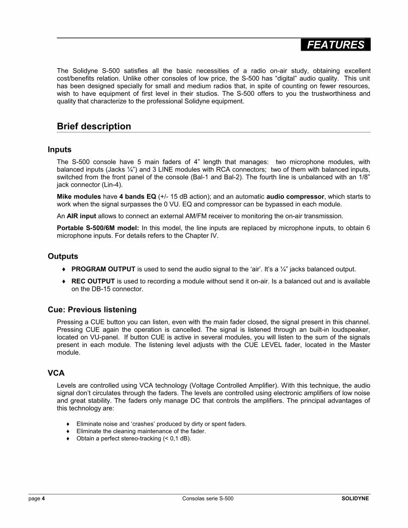
The Solidyne S-500 satisfies all the basic necessities of a radio on-air study, obtaining excellent cost/benefits relation. Unlike other consoles of low price, the S-500 has “digital” audio quality. This unit has been designed specially for small and medium radios that, in spite of counting on fewer resources, wish to have equipment of first level in their studios. The S-500 offers to you the trustworthiness and quality that characterize to the professional Solidyne equipment.
Brief description
InputsThe S-500 console have 5 main faders of 4” length that manages: two microphone modules, with balanced inputs (Jacks ¼”) and 3 LINE modules with RCA connectors; two of them with balanced inputs, switched from the front panel of the console (Bal-1 and Bal-2). The fourth line is unbalanced with an 1/8” jack connector (Lin-4).
Mike modules have 4 bands EQ (+/- 15 dB action); and an automatic audio compressor, which starts to work when the signal surpasses the 0 VU. EQ and compressor can be bypassed in each module.
An AIR input allows to connect an external AM/FM receiver to monitoring the on-air transmission.
Portable S-500/6M model: In this model, the line inputs are replaced by microphone inputs, to obtain 6 microphone inputs. For details refers to the Chapter IV.
Outputs♦ PROGRAM OUTPUT is used to send the audio signal to the ‘air’. It’s a ¼” jacks balanced output.
♦ REC OUTPUT is used to recording a module without send it on-air. Is a balanced out and is available on the DB-15 connector.
Cue: Previous listeningPressing a CUE button you can listen, even with the main fader closed, the signal present in this channel. Pressing CUE again the operation is cancelled. The signal is listened through an built-in loudspeaker, located on VU-panel. If button CUE is active in several modules, you will listen to the sum of the signals present in each module. The listening level adjusts with the CUE LEVEL fader, located in the Master module.
VCALevels are controlled using VCA technology (Voltage Controlled Amplifier). With this technique, the audio signal don’t circulates through the faders. The levels are controlled using electronic amplifiers of low noise and great stability. The faders only manage DC that controls the amplifiers. The principal advantages of this technology are:
♦ Eliminate noise and ‘crashes’ produced by dirty or spent faders.♦ Eliminate the cleaning maintenance of the fader.♦ Obtain a perfect stereo-tracking (< 0,1 dB).
page 4 Consolas serie S-500 SOLIDYNE
CHAPTER 1-Installation
1.1 Connecting the console
Although the S-500 is not a modular console, since it’s mounted on an unique printed board, we will talk about to the different channels denominating them “modules”, by custom of use in other console models. In spite of having an only circuit board, the replacement of the main faders is simple, because these are not welded to the board but that they are mounted to the chassis with screws.
All the I/O connectors are in the rear panel of the cabinet. Remember that a safe and free on faults operation depends of the wiring of the different sources to the console, reason why we recommend you to take the time necessary to make all connections with the greater care and always using material of high quality. A good solution is to acquire the complete cable set (kit Solidyne MNG-500).
1.1.1 Microphone modulesAll microphone inputs are balanced, with connectors Jack ¼” type. Remember that pins 1, 2 and 3 of the XLR connector must be connected to the Plug (TRS) to “sleeve”, “tip” and “ring” respectively, as showed in 1.3 – Connection general diagram.
Phantom power source
The S-500 allows to activate a phantom power source which gives 9-12 VDC (between tip – ring). To use mikes that operates with 48 V phantom, you must use an external power source. Please consult with your Solidyne dealer to acquire external phantom’s; or contact us via e-mail.
¡Warning! Always use balanced connections. Otherwise, hum and noise will can appear.
1.1.2 Line modulesThere are 3 line modules. Each one has 2 stereo inputs, assignable from the front panel. Modules LIN-1 and LIN-2 can be switched between balanced (DB-9) or unbalanced (RCA) inputs. See Table-2 for connection’s details. LIN-3 module can be switched to enter from an RCA input (LIN-3) or a minijack (1/8”) called LIN-4. This input is recommended to connect a PC equipped with a non-professional soundcard.
Each line module has a gain control which affects both inputs. Gain controls compensate the input gain for the differences of the sources, in order to obtain a same output level for equal’s faders positions.
Following the actual engineer criteria, the input impedance is bigger than 10 KOhms (Bridging inputs). This is adequate to all current equipment’s (decks, DAT, Audicom, Mini-disc, CD players, etc.) But if you need to adapt the impedance to 600 Ohms, you must add a 680 Ohms resistor inside the connector, in parallel to the input.
SOLIDYNE Consolas serie S-500 page 5
1.2 Rear Panel
1.2.1 Power SourceThe S-500 works with 28 VCC provided by an external power source. At the left corner of the rear panel is located the power connector (tubular 2.1 mm). Always use the external power source provided with the console. Verify that the AC switch (220/110 V) is in the right position.
Warning! Connect the power source to the console first, and then to the AC line, in order to avoid sparks on the connector.
1.2.2 On-air signal (Tally)On-air output is a tubular connector (2,5 mm internal pin) that gives 12 VDC/0.3A when a mike fader is opened. The output returns to 0 volts when the fader is completely closed.
On-air signal is used for activate a tally light which indicate to the speaker or journalist that the mikes are on-air. A good and professional solution is to acquire the Solidyne On-Air-Light kit: a solid state display of big size. Other option is to use a Stop light used in the cars, or connect a relay to activate another type of light.
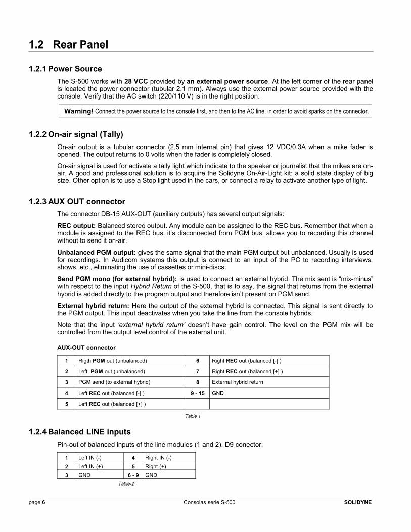
1.2.3 AUX OUT connectorThe connector DB-15 AUX-OUT (auxiliary outputs) has several output signals:
REC output: Balanced stereo output. Any module can be assigned to the REC bus. Remember that when a module is assigned to the REC bus, it’s disconnected from PGM bus, allows you to recording this channel without to send it on-air.
Unbalanced PGM output: gives the same signal that the main PGM output but unbalanced. Usually is used for recordings. In Audicom systems this output is connect to an input of the PC to recording interviews, shows, etc., eliminating the use of cassettes or mini-discs.
Send PGM mono (for external hybrid): is used to connect an external hybrid. The mix sent is “mix-minus” with respect to the input Hybrid Return of the S-500, that is to say, the signal that returns from the external hybrid is added directly to the program output and therefore isn’t present on PGM send.
External hybrid return: Here the output of the external hybrid is connected. This signal is sent directly to the PGM output. This input deactivates when you take the line from the console hybrids.
Note that the input ‘external hybrid return’ doesn’t have gain control. The level on the PGM mix will be controlled from the output level control of the external unit.
AUX-OUT connector
1 Rigth PGM out (unbalanced) 6 Right REC out (balanced [-] )
2 Left PGM out (unbalanced) 7 Right REC out (balanced [+] )
3 PGM send (to external hybrid) 8 External hybrid return
4 Left REC out (balanced [-] ) 9 - 15 GND
5 Left REC out (balanced [+] )
Table 1
1.2.4 Balanced LINE inputsPin-out of balanced inputs of the line modules (1 and 2). D9 conector:
1 Left IN (-) 4 Right IN (-)
2 Left IN (+) 5 Right (+)3 GND 6 - 9 GND
Table-2
page 6 Consolas serie S-500 SOLIDYNE
1.2.5 Monitors & Headphones outputsCONTROL outputs are used to connect the monitor loudspeakers (MON) and the operator’s headphones (PHONE).
STUDIO manages the monitors and headphones for the study cabinet. In both cases the outputs presents stereo minijack connectors (you can connect “multimedia PC speakers” directly to this outputs).
To the monitor loudspeakers outputs (MON) is convenient to use powered loudspeakers, avoiding the use of additional amplifiers. A PC powered loudspeakers of good quality will be sufficient for most of radio studios, being an low cost solution.
All outputs are protected against accidental short-circuits. Each headphone output can manage up to 3 headphones (in parallel).
Muting systemThe output of the studio’s loudspeakers is muted when you open a mike fader, to avoid signal loops. The program signal and the talk-back orders will be listened in one channel of the headphone. As well, when you pulse the talk-back button, the CONTROL loudspeakers are muted to not interfere with the microphone of orders.
1.2.6 Telephone line connectionThe built-in telephone hybrid manages one telephone line. On the rear panel there are two connector RJ11 type: one for the telephone line and other for the associated phone. This phone works normally while the line isn’t taken from the console. The phone line can come directly from the public central telephone offices or a radio’s private central (PBX). The private centrals can deteriorate the hybrid’s reject factor, for what we recommend you to connect the S-500 directly to the public telephone central.
Hybrid’s inputs have internal filters to reject RF, for the mid-waves (AM) and for VHF and UHF, not being necessary, usually, add additional filters.
The level adjustments for send, return and reject factor are calibrated in factory and generally additional adjustments aren’t necessaries. Nevertheless, in case that the voice of the local speaker was altered in its quality when making a telephone conversation, the control of balance of the Hybrid will have to be readjusted. This is made during a telephone conversation, using a very small screwdriver to adjust a preset located below the hybrid’s activation button. It will have to be turned in one or another sense until obtaining that the voice of the speaker of the radio sounds natural, with the same quality that when the Hybrid is disconnected.
Telephone lines must have protection against overshoots despite to accidents or electric storms.
1.2.7 Using an external hybridThe S-500 console is designed to connect an external telephone hybrid, necessary when it’s required to manage two or more lines. To it, it is arranged in connector AUX-OUT a Program Send (mono) that will be connected to the audio input of the external hybrid. The output of the hybrid enters through a special input denominated Hybrid Return of the same connector (see Tabla-1). This input is MIX-MINUS respect to PGM Send, that is to say, the Hybrid’s Return signal is added directly to the program out but he is not present in PGM Send, not to produce a feedback loop. The Hybrid’s Return input is deactivated if the line is taken from the S-500 built-in hybrid. The fader SEND only works with the internal hybrid. There isn’t level control for the signal that enters by Hybrid’s Return. You will have to use the output level control of the external hybrid.
SOLIDYNE Consolas serie S-500 page 7
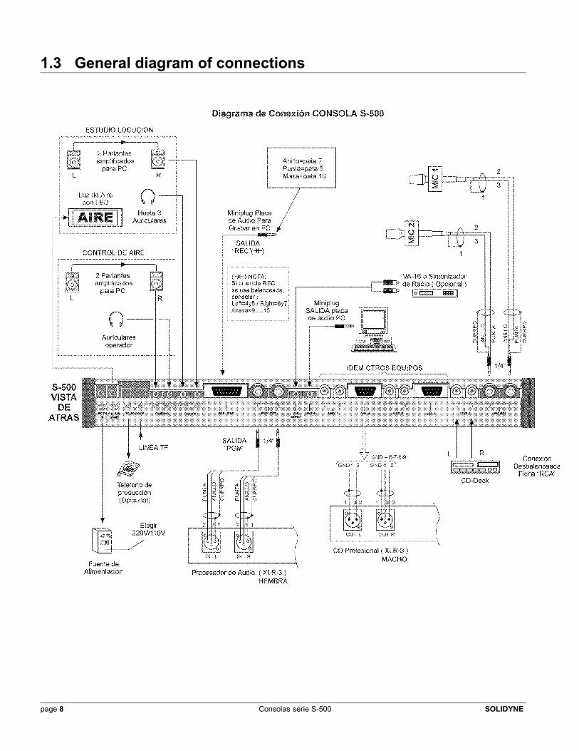
1.3 General diagram of connections
page 8 Consolas serie S-500 SOLIDYNE
CHAPTER 2- Operation -
2.1 Introduction
The audio signals originating of the computer (Audicom); Microphones, Satellites; CD players; etc.; they enter the console through the input channels, that amplify them. The signals of these channels are sent to PGM output (signal sent to the air) or REC output (for internal recording), that are both ways that can cross the signal towards the output connectors.
MICROPHONE modules receive the balanced signal through a stereo Jack (¼”).
LINE modules can receive signal from two stereo sources:
LIN 1 and LIN 2: commutable between unbalanced (RCA) or balanced (DB-9 connector) input. LIN 3: commutable between unbalanced RCA or unbalanced Minijack (LIN-4).
The commutation between inputs is made from a switch in the front of the module. A second switch allows you to assign each module to the outputs PGM or REC.
The VU-meter panel has two vu-meters LED type, for PGM and REC. The action of the audio compressor (mike modules) is indicated by a LED-bar; and a square red LED indicates when the built-in hybrid takes the telephone line.
The MONITORING SECTION, located below the vu-meters, contents the faders that manage the monitoring and hybrid ‘on-air’. Below the vu-meters you will find the talk-back section and the CUE loudspeaker.
2.1.1 Starting upConnect any signal source to a LINE module, e.g. a CD player, and a couple of powered loudspeakers to the CONTROL MON output. Also a microphone can be used, to prove the behavior of the EQ and the compressor. To route a signal that enters a module to the PGM output (on-air), follow the following steps:
a) Select the correspondent input, where you have connected the CD player (RCA, DB9, mini-jack), using LIN-1/BAL-1 or LIN-3/LIN-4 buttons, according to the module used.
b) Assign PGM/REC to the output "PGM".
b) Verify that the signal is present pressing the CUE button. The audio signal should be listened on the built-in CUE loudspeaker.
c) Pick up the fader, the signal should be showed on vu-meters.
d) If you don’t hear the audio, verify on the monitoring section the position of the switches. Both must be at the right, that is to say, STUDIO MONITOR in the position PGM; and CONTROL MONITOR in the position STUDIO MONITOR.
SOLIDYNE Consolas serie S-500 page 9
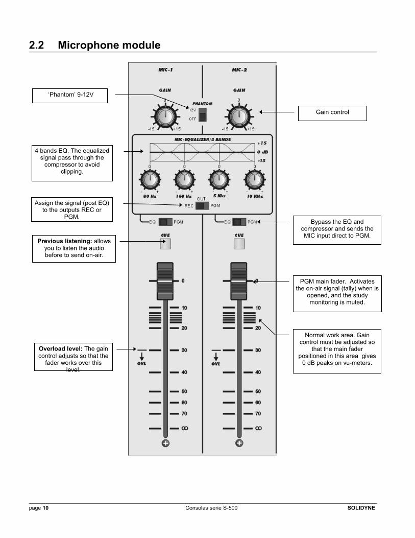
2.2 Microphone module
page 10 Consolas serie S-500 SOLIDYNE
Gain control
‘Phantom’ 9-12V
4 bands EQ. The equalized signal pass through the
compressor to avoid clipping.
PGM main fader. Activates the on-air signal (tally) when is
opened, and the study monitoring is muted.
Overload level: The gain control adjusts so that the
fader works over this level.
Previous listening: allows you to listen the audio before to send on-air.
Assign the signal (post EQ) to the outputs REC or
PGM.Bypass the EQ and
compressor and sends the MIC input direct to PGM.
Normal work area. Gain control must be adjusted so
that the main fader positioned in this area gives
0 dB peaks on vu-meters.
2.2.1 EqualizerThe EQ acts on both microphone channels, but you can bypass it on each channel with the switch EQ/PGM (which acts also on the compressor).
♦ In EQ position, the signal is routed through the EQ and the compressor.♦ In PGM position the signal is sent directly to the program output.
The switch OUT PGM / REC allows you to send the processed signal to the PGM or REC bus output.
EQ bands are: 80 Hz, 160 Hz, 5 KHz y 10 KHz. They can be changed in a range of +/- 15 dB. The central bands are bell-shape type, whereas 80 Hz and 10 KHz bands are shelving type.
When the switch OUT PGM/REC is in REC position, there is not MIC signal at the PGM output, although the EQ/PGM switch is in PGM position.
2.2.2 COMPRESSORThe output of the EQ is sent to an automatic compressor, of very low distortion, designed to reduce the dynamic range of the signal (difference between the maximum and minimum level) without altering the sound. This avoids possible distortions by clipping (saturation), that take place when who speaks elevates much the voice level, or too much approaches the microphone. This is essential for interviews in Study, because it maintains the output level of the console very constant.
As was explained, compressor and EQ stages are activated at the same time with the switch EQ/PGM. Audio signal is compressed only when is over 0 VU. Below this level the compressor doesn’t works. When this threshold is overpasses, the console reduces his gain to maintain constant the output level. By example: if the mike signal increases abruptly 15 dB over 0 VU, the increase at the output will be only of 2 dB.
The actino of the compressor will be indicated by four LED’s which indicates the gain reduction. Obviously, the vu-meters shows the level of the processed signal, that is to say, the real output level.
2.2.3 “Phantom” power sourcePhantom power source are used with microphones that requires external feeding (condenser type). The S-500 gives 9-12 V phantom tension. If you need 48V phantom, you must use an external phantom power source.
Remember: always respect the balanced connections, since if the conections are defective and the phantom power is active, it can produce damages or background noise, even damages to the mike.
2.2.4 Gain adjustmentsAll modules have an overload indication (OVL) printed beside the fader. The rule is:
With signals at 0VU, the main fader must be positioned over the OVL indication
If the fader is under this indication, the input will overload and clip the signal. To obtain and optimums adjustment, open the fader until the area of normal work (grayed zone between 10 dB and 20 dB) and adjust the gain knob until reach peaks of 0 VU in the vu-meters.
SOLIDYNE Consolas serie S-500 page 11
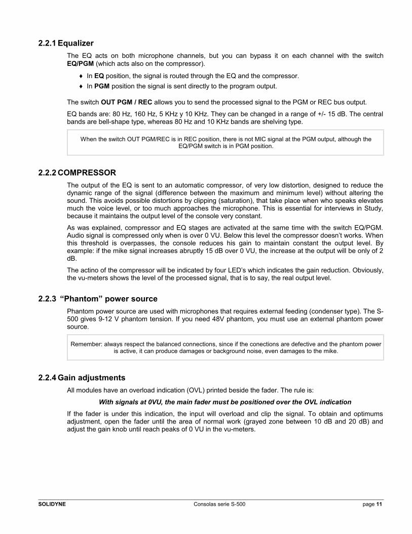
2.3 Line modules
page 12 Consolas serie S-500 SOLIDYNE
Previous listening (CUE): Pressing this button, you can hear the audio on the built-in speaker,
even when the main fader is closed.
Input selector: switch between unbalanced (RCA)
or balanced (D9) inputs. [Minijack LIN-4 on LIN-3
module].
Output assignment:
The signal can be sent to PGM (on-air) or REC.
Gain control
Overload level: The gain control adjusts so that the fader works
over this level.
Area of normal work. Gain control must be adjusted so
that the main fader positioned in this area gives 0 dB peaks on vu-meters.
2.4 Recordings
The S-500 has two stereo outputs. One is used to send the signal on-air, called Program (PGM). The other one is denominated REC and typically is used for recordings. All modules can be routed to PGM or to REC outputs, but not to both outputs simultaneously.
NOTE: When the console is used in a Production Study, you must use the PGM output to send signal to audio recorders, in order to be able for record the telephonic interviews, since the hybrid is routed only to PGM.
The signal of the built-in hybrid is added to the PGM output directly, thence, to record in the Air Study all the emitted on-air, even the hybrid, you will must to use the unbalanced PGM output (connector AUX-OUT).
To make a recording, select previously the source channels. By example: supposes that while a musical program is on-air from a CD player, you want to record a commercial cut from a mini-disc to hard disk.
a) Select in the Monitoring Section the output bus ‘REC’, using the switch CONTROL MONITOR, to listen only the signal that you will record.
b) Switch the buttons PGM/REC to the position “REC” in the mini-disc’s module. Remember that the audio don’t be on-air, it will be sent only to the PC through the output REC. To check it, change the position of the CONTROL MONITOR switch.
Now, you can start the recording on the PC. The recording output level is showed by the REC vu-meter of the S-500. When the recording ends; leave all the controls to their normal position.
2.5 Monitoring, hybrid and vu-meters
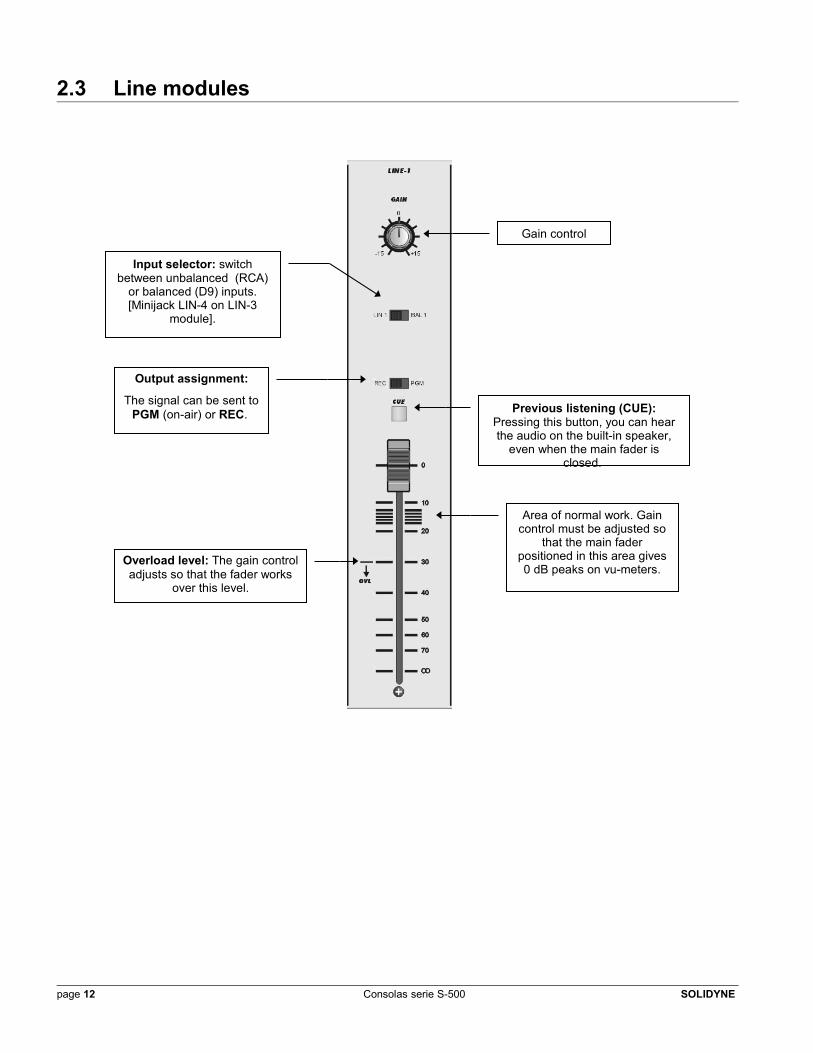
2.5.1 Monitoring sectionThis control manages the level of the signals sent to the Studio (STUDIO CONTROL) and the Control Room (CONTROL MONITOR). In both cases, an unique knob manages the level for headphones and monitor loudspeakers. This simplified design was developed to use the S-500 with active speakers that have their own level control, by means of which it adjusts to the relation of levels between the headphones and the loudspeakers.
AIR/PGM switch allows to monitoring the on-air signal from console output or to listen the real transmission from air, using an external receiver connected to the AIR input (rear panel). This signal sends to the Studio. In the Control Room, the operator can listen the on-air signal directly from PGM output or from the air, according to the AIR/PGM status, or to listen the REC output.
2.5.2 Previous listening (CUE)Pressing the CUE button at any input module, the audio will be listened on the built-in CUE loudspeaker, even when the main fader is closed. The volume for the CUE speaker controls with the CUE LEVEL knob. You can press two or more CUE buttons at the same time to cueing several signals.
SOLIDYNE Consolas serie S-500 page 13
2.5.3 Talk-backTo send orders to the Study, press and hold the Talk-back button. To speak directing the voice towards the microphone; it is not necessary to approach too much. Program audio reproduced by the Control Room monitors it will be muted to avoid feedback loops and will be listen the operator’s voice in the Study through the loudspeakers. If these were muted (MIC fader open); the orders will not be listened in loudspeakers. They only will be listened by headphones. In both cases, the orders will be listened on the left channel, while in the other channel the program signal stays for reference.
In order to engage in a dialog with the speaker, press CUE in the microphone module. Must special well-taken care of with the CUE level to avoid feedbacks with the microphone of orders.
2.5.4 VU-metersThe main VU-meters is stereo and corresponds to the PGM bus. The scale is expressed in dBm, indicating the level of the balanced PGM output.
A secondary mono vu-meter shows the REC level, adding the L&R channels.
The compressor action is indicated by a LED’s bar (MIC COMP) that lights indicating the attenuation applied to the signal.
LED HYBRID lights when the telephone line is taken in the console.
2.5.5 Operation of the telephonic HybridThe operation of the hybrid is very simple. The calls are established from the associated telephone, or that the call becomes from that telephone that is an incoming call. When you want to put the telephone on-air, verify that fader SEND is closed and to take the line in the console pressing button TELEPHONE HYBRID. A red LED will light in the vu-meters panel indicating that the line is taken. Hang up the associate telephone. In this condition, the person who is waiting receives the program signal, that is to say, they will listen the radio through the telephone. If once taken the line you wish to return to speak with the caller, you can pick up the telephone and speak normally, even maintaining taken the line in the console.
To put the call on-air: open fader SEND until reaching a correct level, measured in the PGM vu-meters. In order to quit the line of the air, close the fader and then release the button. Not cut the communications directly from the button because can cause a ‘plop' on-air. If you wishes to quit the line of the air but to maintain a communication, pick up the associated phone before releasing the line in the console. The call will have left derivative to the phone again.
page 14 Consolas serie S-500 SOLIDYNE
CHAPTER 3-Maintenance -
In order to obtain from the S-500 console the excellent benefits that Solidyne guarantees with its design and manufacture, we recommended to follow the indicated operative procedures of this manual.
3.1 CleaningThe front of the modules and the cabinet in general will be cleaned using a very smooth detergent (of the type used for painted walls or papering) and a sponge or fine cloth. DON’ T USE alcohol, benzene neither other derivatives of petroleum.
Avoid the dust accumulation on the equipment. Don’t smoke while operates the console, the cigarette also is injurious for audio consoles, since the ash accumulation in the faders reduces its life utility remarkably.
The main faders are of high quality, Polished Coal type. They manages only DC and its duration, in normal conditions of operation, exceeds a million operations.
3.2 Spare partsIn order to change a fader it’s not necessary to disassemble the entire console. It will be enough to remove the base of the S-500, by quitting the 9 screws. The faders are accessible since are not welded to the circuit board. To retire each fader simply quit both screws that hold it to the panel and to weld the new unit. The spare part of switches or buttons is made removing the knobs from the console and retiring the printed board, relaxing the screws that hold it.
KIT OF SPARE PARTS (Code SPARE500): Kit of general spare parts for the console can be acquired, which includes integrated circuit, transistors, LED's, buttons, switches and faders.
NOTE : The Service Manual, with includes schematics and components distribution diagrams, is sent without charge to fully qualified technical personal who approves the Solidyne training curses
SOLIDYNE Consolas serie S-500 page 15

page 16 Consolas serie S-500 SOLIDYNE
CHAPTER 4Portable console S-500/6M
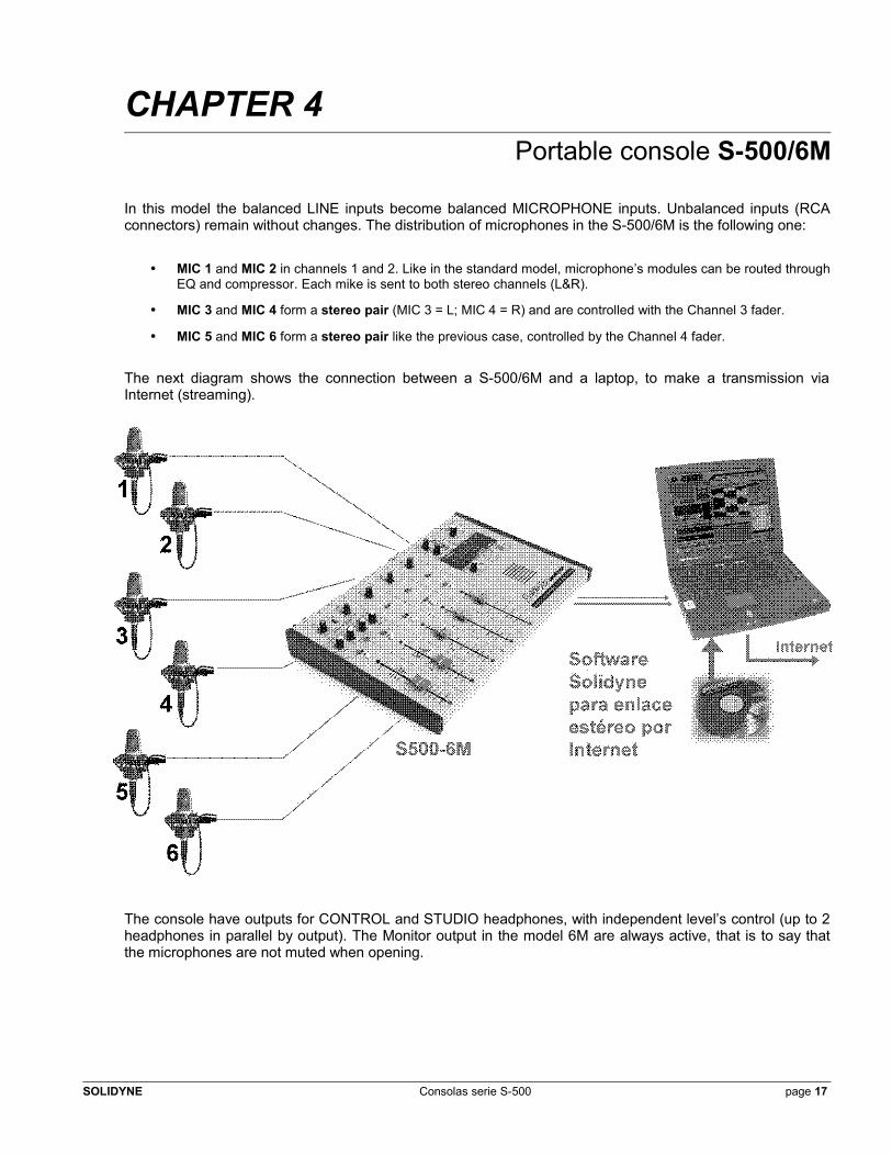
In this model the balanced LINE inputs become balanced MICROPHONE inputs. Unbalanced inputs (RCA connectors) remain without changes. The distribution of microphones in the S-500/6M is the following one:
• MIC 1 and MIC 2 in channels 1 and 2. Like in the standard model, microphone’s modules can be routed through EQ and compressor. Each mike is sent to both stereo channels (L&R).
• MIC 3 and MIC 4 form a stereo pair (MIC 3 = L; MIC 4 = R) and are controlled with the Channel 3 fader.
• MIC 5 and MIC 6 form a stereo pair like the previous case, controlled by the Channel 4 fader.
The next diagram shows the connection between a S-500/6M and a laptop, to make a transmission via Internet (streaming).
The console have outputs for CONTROL and STUDIO headphones, with independent level’s control (up to 2 headphones in parallel by output). The Monitor output in the model 6M are always active, that is to say that the microphones are not muted when opening.
SOLIDYNE Consolas serie S-500 page 17
When you operate connected to the study by telephone line, you must select the mode “PGM" for STUDIO and CONTROL monitors. This form, the conversation generated in microphones (1, 2, 3 and 4) , 2, 3 and 4 as the return’s signal from the STUDIO of the RADIO, will be listened on the headphones too.
If you need to connect a second console, they can be connected though LINE of Channel 5.
If you want to monitor with loudspeakers, you can use active speakers (like the used on the PC's) on the STUDIO MON or CONTROL MON outputs. Take care with the distance between microphones and monitors, to avoid feedback loops.
Positioning mikes in stereoTake in mind that the pairs of stereo microphones (3/4 and 5/6) must be located to each other separated. Example: in order to take a piano from tail distances of 1 to 2 meters they are advised. In order to take a small orchestra it agrees to separate between 2 and 3 meters the microphones of the stereo pair. In all the cases the singers must be taken more close possible and with microphones 1 and 2.
An alternative technique to recording takes for big orchestras is to use “coincident microphones”. This technique consists in to create the stereo image using directional microphones (cardioids). For it, their axes mount in the same support crossing 90 degrees. This technique, denominated microphones BLUMLEIN, is one of the favorites in Europe to take the orchestra and the environmental reverberation.
page 18 Consolas serie S-500 SOLIDYNE
CHAPTER 5TTechnical specificationss
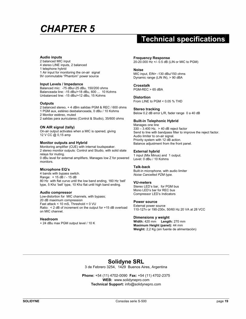
Audio inputs2 balanced MIC input4 stereo LINE inputs, 2 balanced1 telephone hybrid1 Air input for monitoring the on-air signal9V commutable “Phantom” power source
Input Levels / ImpedanceBalanced mic: -75 dBu/-25 dBu, 150/200 ohmsBalanceada line: -15 dBu/+18 dBu, 600 ... 10 KohmsUnbalanced line: -15 dBu/+12 dBu, 15 Kohms
Outputs2 balanced stereo, + 4 dBm salidas PGM & REC / 600 ohms1 PGM aux, estéreo desbalanceada, 0 dBu / 10 Kohms2 Monitor estéreo, muted2 salidas para auriculares (Control & Studio), 35/600 ohms
ON AIR signal (tally)On-air output activates when a MIC is opened, giving 12 V CC @ 0,15 amp Monitor outputs and HybridMonitoring amplifier (CUE) with internal loudspeaker.2 stereo monitor outputs: Control and Studio, with solid state relays for muting.0 dBu level for external amplifiers. Manages low Z for powered monitors.
Microphone EQ’s4 bands with bypass switch.Range: + 15 dB / - 15 dB80 Hz with flat curve until the low band ending, 160 Hz ‘bell’ type, 5 Khz ‘bell’ type, 10 Khz flat until high band ending.
Audio compressorLow-distortion for MIC channels, with bypass;20 dB maximum compression Fast attack < 10 mS, Threshold = 0 VU Ratio: < 2 dB of increment on the output for +15 dB overload on MIC channel.
Headroom+ 24 dBu max PGM output level / 10 K
Frequency Response20-20.000 Hz +/- 0.5 dB (LIN or MIC to PGM)
NoiseMIC input, EIN= -130 dBu/150 ohms Dynamic range (LIN IN), > 90 dBA
CrosstalkPGM-REC > 65 dBA
DistortionFrom LINE to PGM < 0.05 % THD
Stereo trackingBelow 0.2 dB error L/R, fader range 0 a 40 dB
Built-in Telephonic HybridManages one line330 – 3.400 Hz, > 40 dB reject factorSend to line with bandpass filter to improve the reject factor. Audio limiter to on-air signal.Priority system with 12 dB action.Balance adjustment from the front panel.
External hybrid1 input (Mix Minus) and 1 output.Level: 0 dBu / 10 Kohms
Talk-backBuilt-in microphone, with audio limiter Noise Cancelled PZM type.
VU-metersStereo LED’s bar, for PGM busMono LED’s bar for REC busCompressor LED’s Indicators
Power sourceExternal power source110-127v or 190-230v, 50/60 Hz 20 VA at 28 VCC
Dimensions y weightWidth: 420 mm Length: 270 mmMaximum Height (panel): 44 mmWeight: 2,2 Kg (sin fuente de alimentación)
Solidyne SRL3 de Febrero 3254, 1429 Buenos Aires, Argentina
Phone: +54 (11) 4702-0090 Fax: +54 (11) 4702-2375WEB: www.solidynepro.com
Technical Support: [email protected]
SOLIDYNE Consolas serie S-500 page 19