Embed Size (px)
DESCRIPTION
Fagor 8040 erorr
Citation preview

Error solving Manual(T model)
Ref 0204-ing

Page 2 of 64
ERROR SOLVING MANUAL (T MODEL)

ERROR SOLVING MANUAL (T MODEL)
Page 3 of 64
INDEX
Programming errors .......................................................................................5
Block preparation and execution errors.....................................................31
Hardware errors ............................................................................................46
PLC errors......................................................................................................48
Servo errors...................................................................................................49
CAN errors.....................................................................................................54
Table data errors ...........................................................................................56
Errors of the TC work mode.........................................................................58

Page 4 of 64
ERROR SOLVING MANUAL (T MODEL)

ERROR SOLVING MANUAL (T MODEL)
Programming errors
Page 5 of 64
PROGRAMMING ERRORS
0001 ‘Línea vacía.’
Detection While editing at the CNC or while executing a program transmitted via DNC.
Cause The various causes might be:1. When trying to enter into a program or execute an empty block or containing the
label (block number).2. In the “Pattern repeat canned cycle (G66)”, “Roughing canned cycle along the
X axis (G68)” or “Roughing canned cycle along the Z axis (G69)” when parameter “S” (beginning of profile) is greater than parameter “E” (end of profile).
Solution The solution for each cause is:1. The CNC cannot enter into the program or execute an empty line. To enter an
empty line in the program, use the «;» symbol at the beginning of that block. The CNC will ignore the rest of the block.
2. The value of parameter “S” (block where the profile definition begins) must be lower than the value of parameter “E” (block where the profile definition ends).
0002 ‘Improper data’
Detection While editing at the CNC or while executing a program transmitted via DNC.
Cause The various causes might be:1. When editing an axis coordinate after the cutting conditions (F, S, T or D) or the
«M» functions.
2. When the marks of the block skip (conditional block /1, /2 or /3) are not at the beginning of the block.
3. When programming a block number greater than 9999 while programming in ISO code.
4. While programming in high-level, the value of the RPT instruction exceeds 9999.
Solution The solution for each cause is:1. Remember the programming order
2. Remember the programming order- Block skip (conditional block /1, /2 or /3).- Label (N).- «G» functions.- Axis coordinates. (X, Y, Z…).- Machining conditions (F, S, T, D).- «M» functions.
3. Correct the syntax of the block. Program the labels between 0 and 9999
4. Correct the syntax of the block. Program a number of repetitions between 0 and 9999
0003 ‘Improper data order.’
Detection While editing at the CNC or while executing a program transmitted via DNC.
Cause The machining conditions or the tool data have been programmed in the wrong order.
Solution Remember that the programming order is:… F...S...T...D...…
All the data need not be programmed.
0004 ‘No more information allowed in the block.’
Detection While editing at the CNC or while executing a program transmitted via DNC.
Cause The various causes might be:1. When editing a «G» function after an axis coordinate.2. When trying to edit some data after a «G» function (or after its associated
parameters) which must go alone in the block (or which only admits its own associated data).
3. When assigning a numeric value to a parameter that does not need it.
Solution The solution for each cause is:

Page 6 of 64
ERROR SOLVING MANUAL (T MODEL)
Programming errors
1. Remember that the programming order is:- Block skip (conditional block /1, /2 or /3).- Label (N).- «G» functions.- Axis coordinates. (X, Y, Z…).- Machining conditions (F, S, T, D).- «M» functions.
2. There are some «G» functions which carry associated data in the block. Maybe, this type of functions do not let program other type of information after their associated parameters. On the other hand, neither machining conditions, (F, S), tool data (T, D) nor «M» functions may be programmed.
3. There are some «G» functions having certain parameters associated to them which do not need to be defined with values.
0005 ‘Repeated information’
Detection While editing at the CNC or while executing a program transmitted via DNC.
Cause The same data has been entered twice in a block.
Solution Correct the syntax of the block. The same data cannot be defined twice in a block.
0006 ‘Improper data format’
Detection While editing at the CNC or while executing a program transmitted via DNC.
Cause While defining the parameters of a machining canned cycle, a negative value has been assigned to a parameter which only admits positive values.
Solution Verify the format of the canned cycle. In some canned cycles, there are parameters which only accept positive values.
0007 ‘Incompatible G functions.’
Detection While editing at the CNC or while executing a program transmitted via DNC.
Cause The various causes might be:1. When programming in the same block two «G» functions which are
incompatible with each other.
2. When trying to define a canned cycle in a block containing a nonlinear movement (G02, G03, G08, G09, G33).
Solution The solution for each cause is:1. There are groups of «G» functions which cannot go together in the block
because they involve actions incompatible with each other. For example:G01/G02: Linear and circular interpolationG41/G42: Left-hand or right-hand tool radius compensation.
This type of functions must be programmed in different blocks.2. A canned cycle must be defined in a block containing a linear movement. In
other words, to define a cycle, a “G00” or a “G01” must be active. Nonlinear movements (G02, G03, G08 and G09) may be defined in the blocks following the profile definition.
0008 ‘Nonexistent G function’
Detection While editing at the CNC or while executing a program transmitted via DNC.
Cause A nonexistent «G» function has been programmed.
Solution Check the syntax of the block and verify that a different «G» function is not being edited by mistake.
0009 ‘No more G functions allowed’
Detection While editing at the CNC or while executing a program transmitted via DNC.
Cause A «G» function has been programmed after the machining conditions or after the tool data.
Solution Remember that the programming order is:- Block skip (conditional block /1, /2 or /3).- Label (N).- «G» functions.- Axis coordinates. (X,Y,Z…).- Machining conditions (F, S, T, D).- «M» functions.

ERROR SOLVING MANUAL (T MODEL)
Programming errors
Page 7 of 64
0010 ‘No more M functions allowed’
Detection While editing at the CNC or while executing a program transmitted via DNC.
Cause More than 7 «M» functions have been programmed in a block.
Solution The CNC does not let program more than 7 «M» functions in a block. To execute any other functions, write them in a separate block. The «M» functions may go alone in a block.
0011 ‘This G or M function must be alone.’
Detection While editing at the CNC or while executing a program transmitted via DNC.
Cause The block contains either a «G» or an «M» function that must go alone in the block.
Solution Write it alone in the block.
0012 ‘Program F, S, T, D before the M functions.’
Detection While editing at the CNC or while executing a program transmitted via DNC.
Cause A machining condition (F, S) or tool data (T, D) has been programmed after the «M» functions.
Solution Remember that the programming order is:… F...S...T...D...M—
Up to 7 «M» functions may be programmed .
All the data need not be programmed.
0013 ‘Program G30 D +/-359.9999’
No explanation required
0014 ‘Do not program labels by parameters.’
Detection While editing at the CNC or while executing a program transmitted via DNC.
Cause A label (block number) has been defined with a parameter.
Solution Programming the block number is optional, but it cannot be defined with a parameter It can only be defined with a number between 0 and 9999.
0015 ‘Number of repetitions not possible.’
Detection While editing at the CNC or while executing a program transmitted via DNC.
Cause A repetition has been programmed wrong or the block does not admit repetitions.
Solution High level instructions do not admit a number of repetitions at the end of the block. To do a repetition, assign to the block to be repeated a label (block number) and use the RPT instruction.
0016 ‘Program: G15 o G15 C.’
Detection While editing at the CNC or while executing a program transmitted via DNC.
Cause An attempt has been made to execute an operation on the “C” axis, but the axis is not active.
Solution In order to operate with the “C” axis, it must be activated first using the “G15” function.
0017 ‘Program: G16 axis-axis.’
Detection While editing at the CNC or while executing a program transmitted via DNC.
Cause In the function «Main plane selection by two axes (G16)» one of the two parameters for the axes has not been programmed.
Solution Check the syntax of the block. The definition of the “G16” function requires the name of the axes defining the new work plane.
0018 ‘Program: G22 K(1/2/3/4) S(0/1/2).’
Detection While editing at the CNC or while executing a program transmitted via DNC.
Cause In the function «Enable/Disable work zones (G22)» the type of enable or disable of the work zone has not been defined or it has been assigned the wrong value.

Page 8 of 64
ERROR SOLVING MANUAL (T MODEL)
Programming errors
Solution The parameter for enabling or disabling the work zones “S” must always be programmed and it may take the following values.
S=0: The work zone is disabled.S=1: It is enabled as a no-entry zone.S=2: It is enabled as a no-exit zone.
0019 ‘Program: work zone K1, K2, K3 or K4.’
Detection While editing at the CNC or while executing a program transmitted via DNC.
Cause The various causes might be:1. A “G20”, “G21” or “G22” function has been programmed without defining the
work zone K1, K2, K3 or K4.2. The programmed work zone is smaller than 0 or greater than 4.
Solution The solution for each cause is:1. The programming format for functions “G20”, “G21” and “G22” is:
Where:
2. The “K” work zone may only have the values of K1, K2, K3 or K4.
0020 ‘Program G36-G39 with R+5.5.’
Detection While editing at the CNC or while executing a program transmitted via DNC.
Cause In the “G36” or “G39” function, the “R” parameter has not been programmed or it has been assigned a negative value.
Solution To define “G36” or “G39”, parameter “R” must also be defined and with a positive value).
0021 ‘Program: G72 S5.5 or axis (axes).’
Detection While editing at the CNC or while executing a program transmitted via DNC.
Cause The various causes might be:1. When programming a general scaling factor (G72) without the scaling factor to
apply.
2. When programming a particular scaling factor (G72) to several axes, but the axes have been defined in the wrong order.
Solution Remember that the programming format for this function is:
0023 ‘Block incompatible when defining a profile.’
Detection While editing at the CNC or while executing a program transmitted via DNC.
Cause In the set of blocks defining a profile, there is a block containing a «G» function that cannot be part of the profile definition.
G20 K...X...C±5.5 Definition of lower work zone limitsG21 K...X...C±5.5 Definition of upper work zone limits.G22 K...S— Enable/disable work zones.
K : Is the work zone.X...C Are the axes where the limits are defined.S Is the type of work zone enable.
G36 R= Rounding radius.G39 R= Distance between the end of the programmed path and the point to
be chamfered.
G72 S5.5” When applying a general scaling factor (to all axes). G72 X…C5.5” When applying a particular scaling factor to one or several
axes.

ERROR SOLVING MANUAL (T MODEL)
Programming errors
Page 9 of 64
Solution The «G» functions available in the profile definition are:G00: Beginning of the profile.G01: Linear interpolation.G02/G03: Clockwise/counterclockwise interpolation.G06: Circle center in absolute coordinates.G08: Arc tangent to previous path.G09: Three point arc.G36: Controlled corner roundingG39: Chamfer.G53: Programming with respect to home.G70/G71: Inch/metric programming.G90/G91: Programming in absolute/incremental coordinates.G93: Polar origin preset.
0024 ‘High level blocks not allowed when defining a profile.’
Detection While editing at the CNC or while executing a program transmitted via DNC.
Cause Within the set of blocks defining a profile, a high level block has been programmed.
Solution Profiles must be defined in ISO code. High level instructions are not allowed (GOTO, MSG, RPT ...).
0025 ‘Program: G77 axes (2 to 6) or G77 S.’
Detection While editing at the CNC or while executing a program transmitted via DNC.
Cause In the “axis slaving function (G77)» the parameters for the axes are missing or in “spindle synchronization (G77S) functions the “S” parameter is missing.
Solution In the “axis slaving” function, program at least two axes and in the “spindle synchronization” function, always program the “S” parameter.
0026 ‘Program: G93 IJ.’
Detection While editing at the CNC or while executing a program transmitted via DNC.
Cause In the «Polar origin preset (G93)» function, some of the parameters for the new polar origin have not been programmed.
Solution Remember that the programming format for this function is:G93 I...J...
The “I”, “J” values are optional, but if programmed, both must be programmed and they indicate the new polar origin.
0028 ‘G2 or G3 not allowed when programming a canned cycle.’
Detection While editing at the CNC or while executing a program transmitted via DNC.
Cause A canned cycle has been attempted to execute while the “G02”, “G03” or “G33” functions were active.
Solution To execute a canned cycle, “G00” or “G01” must be active. A “G02” or “G03” function may be programmed previously in the program history. Check that these functions are not active when the canned cycle is defined.
0029 ‘G84-85: X Z Q R C [D L M F H] I K.’
Detection While editing at the CNC or while executing a program transmitted via DNC.
Cause The parameters of the canned cycle for “Turning of curved sections (G84)” or for “Facing curved sections (G85)” have been programmed wrong. These may be the probable causes:1. Some mandatory parameter is missing.
2. The parameters of the cycle have not been edited in the correct order.3. A parameter has been programmed which does not match the calling format.
Solution The following parameters must be programmed in this cycle:
The rest of the parameters are optional. The parameters must be edited in the order indicated by the error message.
X-Z : Profile starting pointQ-R : Profile end pointC : Cutting passI-K : Distance from the starting point to the arc center.

Page 10 of 64
ERROR SOLVING MANUAL (T MODEL)
Programming errors
0030 ‘G86-87: X Z Q R I B [D L] C [J A].’
Detection While editing at the CNC or while executing a program transmitted via DNC.
Cause The parameters of the canned cycle for “longitudinal threadcutting (G86)” or for “face threadcutting (G87)” have been programmed wrong. These may be the probable causes:1. Some mandatory parameter is missing.2. The parameters of the cycle have not been edited in the correct order.
3. A parameter has been programmed which does not match the calling format.
Solution The following parameters must be programmed in this cycle:
The rest of the parameters are optional. The parameters must be edited in the order indicated by the error message.
0031 ‘G88-G98: X Z Q R [C D K].’
Detection While editing at the CNC or while executing a program transmitted via DNC.
Cause The parameters of the canned cycle for “grooving along X (G88)” or “grooving along Z (G89)” have been programmed wrong. These may be the probable causes:1. Some mandatory parameter is missing.2. The parameters of the cycle have not been edited in the correct order.3. A parameter has been programmed which does not match the calling format.
Solution The following parameters must be programmed in this cycle:
The rest of the parameters are optional. The parameters must be edited in the order indicated by the error message.
0032 ‘G66: X Z I C [A L M H] S E.’
Detection While editing at the CNC or while executing a program transmitted via DNC.
Cause The parameters of the «Pattern repeat canned cycle with islands (G66)» have been programmed wrong. These may be the probable causes:1. Some mandatory parameter is missing.2. The parameters of the cycle have not been edited in the correct order.3. A parameter has been programmed which does not match the calling format.
Solution The following parameters must be programmed in this cycle:
The rest of the parameters are optional. The parameters must be edited in the order indicated by the error message.
0033 ‘G68-G69: X Z C [D L M F H] S E .’
Detection While editing at the CNC or while executing a program transmitted via DNC.
Cause The parameters of the canned cycle for “roughing along X (G68)” or “roughing along Z (G69)” have been programmed wrong. These may be the probable causes:1. Some mandatory parameter is missing.2. The parameters of the cycle have not been edited in the correct order.3. A parameter has been programmed which does not match the calling format.
Solution The following parameters must be programmed in this cycle:
The rest of the parameters are optional. The parameters must be edited in the order indicated by the error message.
X-Z : Starting point of the thread.Q-R : End point of the thread.I : Thread depth.B : Cutting passC : Thread pitch.
X-Z : Starting point of the groove.Q-R : End point of the groove.
X-Z : Profile starting pointI : Residual stock.C : Cutting passS : Block where the profile geometry description begins.E : Block where the profile geometry description ends.
X-Z : Profile starting pointC : Cutting passS : Block where the profile geometry description begins.E : Block where the profile geometry description ends.

ERROR SOLVING MANUAL (T MODEL)
Programming errors
Page 11 of 64
0034 ‘G81-G82: X Z Q R C [D L M F H].’
Detection While editing at the CNC or while executing a program transmitted via DNC.
Cause The parameters of the canned cycle for “Turning of straight sections (G81)” or for “Facing straight sections (G82)” have been programmed wrong. These may be the probable causes:1. Some mandatory parameter is missing.2. The parameters of the cycle have not been edited in the correct order.
3. A parameter has been programmed which does not match the calling format.
Solution The following parameters must be programmed in this cycle:
The rest of the parameters are optional. The parameters must be edited in the order indicated by the error message.
0035 ‘G83: X Z I B [D K H C].’
Detection While editing at the CNC or while executing a program transmitted via DNC.
Cause The parameters have been programmed wrong in the «Axial drilling/tapping cycle (G83)». These may be the probable causes:1. Some mandatory parameter is missing.
2. The parameters of the cycle have not been edited in the correct order.3. A parameter has been programmed which does not match the calling format.
Solution The following parameters must be programmed in this cycle:
The rest of the parameters are optional. The parameters must be edited in the order indicated by the error message.
0036 ‘G60-G61: X Z I B Q A J [D K H C] S.’
Detection While editing at the CNC or while executing a program transmitted via DNC.
Cause The parameters of the canned cycle for “face drilling or tapping (G60)” or for “longitudinal drilling or tapping (G61)” have been programmed wrong. These may be the probable causes:1. Some mandatory parameter is missing.2. The parameters of the cycle have not been edited in the correct order.3. A parameter has been programmed which does not match the calling format.
Solution The following parameters must be programmed in this cycle:
The rest of the parameters are optional. The parameters must be edited in the order indicated by the error message.
0037 ‘G62-G63: X Z L I Q A J [D] F S.’
Detection While editing at the CNC or while executing a program transmitted via DNC.
Cause The parameters of the canned cycle for “longitudinal slot milling (G62)” or “face slot milling (G62)” have been programmed wrong. These may be the probable causes:1. Some mandatory parameter is missing.2. The parameters of the cycle have not been edited in the correct order.
Solution The following parameters must be programmed in this cycle:
X-Z : Profile starting pointQ-R : Profile end pointC : Cutting pass
X-Z : Machining position.I : Machining depth.B : Type of operation.
X-Z : Machining position.I : Machining depth.B : Type of operation.Q : Angular position of the first machining operation.A : Angular step between machining operations.J : Number of machining operations.S : Speed and turning direction of the live tool.
X-Z : Slot position.L : Slot length.I : Slot depth.Q : Angular position of the first slot.A : Angular step between slots.J : Number of slots.

Page 12 of 64
ERROR SOLVING MANUAL (T MODEL)
Programming errors
The rest of the parameters are optional. The parameters must be edited in the order indicated by the error message.
0043 ‘Incomplete Coordinates.’
Detection While editing at the CNC or while executing a program transmitted via DNC.
Cause The various causes might be:1. During simulation or execution, when trying to make a movement defined with
only one coordinate of the end point or without defining the arc radius while a «circular interpolation (G02/G03) is active.
2. During editing, when editing a circular movement (G02/G03) by defining only one coordinate of the end point or not defining the arc radius.
Solution The solution for each cause is:1. A “G02” or “G03” function may be programmed previously in the program
history. In this case, to make a move, both coordinates of the end point and the arc radius must be defined. To make a linear movement, program “G01”.
2. To make a circular movement (G02/G03), both coordinates of the end point and the arc radius must be programmed.
0044 ‘Incorrect Coordinates.’
Detection During the execution in programs transmitted via DNC.
Cause An attempt has been made to execute a block syntactically incorrect (G1 X20K-15)
Solution Correct the syntax of the block.
0045 ‘Polar coordinates not allowed.’
Detection While editing at the CNC or while executing a program transmitted via DNC.
Cause When «Programming with respect to home (G53)», the end point has been defined in polar or cylindrical coordinates or in Cartesian coordinates with an angle.
Solution When programming with respect to home, only Cartesian coordinates may be programmed.
0046 ‘Axis does not exist.’
Detection While editing at the CNC or while executing a program transmitted via DNC.
Cause A block has been edited whose execution involves the movement of a nonexistent axis.
Solution Check that the axis name being edited is correct.
0047 ‘Program axes.’
Detection While editing at the CNC or while executing a program transmitted via DNC.
Cause No axis has been programmed in a function requiring an axis.
Solution Some instructions require the programming of axes (REPOS, G14, G20, G21…).
0048 ‘Incorrect order of axes.’
Detection While editing at the CNC or while executing a program transmitted via DNC.
Cause The axis coordinates have not been programmed in the correct order or an axis has been programmed twice in the same block.
Solution Remember that the correct programming order for the axes is: X...Y...Z...U...V...W...A...B...C—
All axes need not be programmed:
0049 ‘Point incompatible with active plane.’
Detection While editing at the CNC or while executing a program transmitted via DNC.
Cause The various causes might be:1. When trying to do a circular interpolation, the end point is not in the active plane.
2. When trying to do a tangential exit in a path that is not in the active plane.
Solution The solution for each cause is:1. Maybe a plane has been defined with “G16”, “G17”, “G18” or “G19”. In this case,
circular interpolations can only be carried out on the main axes defining that
F : Feedrate.S : Speed and turning direction of the live tool.

ERROR SOLVING MANUAL (T MODEL)
Programming errors
Page 13 of 64
plane. To define a circular interpolation in another plane, it must be defined beforehand.
2. Maybe a plane has been defined with “G16”, “G17”, “G18” or “G19”. In this case, corner rounding, chamfers and tangential entries/exits can only be carried out on the main axes defining that plane. To do it in another plane, it must be defined beforehand.
0050 ‘Program positions on active plane.’
No explanation required
0051 ‘Perpendicular axis included in active plane.’
No explanation required
0052 ‘Center of circle programmed incorrectly.’
No explanation required
0053 ‘Program pitch.’
Detection While editing at the CNC or while executing a program transmitted via DNC.
Cause In the «Electronic threading cycle (G33)» the parameter for the thread pitch is missing.
Solution Remember that the programming format for this function is:G33 X...C...L...
Where: “L” is the thread pitch.
0054 ‘Pitch programmed incorrectly.’
Detection While editing at the CNC or while executing a program transmitted via DNC.
Cause A helical interpolation has been programmed with the wrong or negative pitch.
Solution Remember that the programming format is:G02/G03 X...Y...I...J...Z...K...
Where: “K” is the helical pitch (always positive value).
0055 ‘Positioning axes or Hirth axes not allowed’
No explanation required
0056 ‘The axis is already slaved.’
No explanation required
0057 ‘Do not program a slaved axis.’
Detection While editing at the CNC or while executing a program transmitted via DNC.
Cause The various causes might be:1. When trying to move an axis alone while being slaved to another one.2. When trying to slave an axis that is already slaved using the G77 function
«Electronic axis slaving».
Solution The solution for each cause is:1. A slaved axis cannot be moved separately. To move a slaved axis, its master
axis must be moved. Both axes will move at the same time.Example: If the Y axis is slaved to the X axis, an X axis move must be programmed in order to move the Y axis (together with the X axis).To unslave the axes, program “G78”.
2. An axis cannot be slaved to two different axes at the same time. To unslave the axes, program “G78”.
0058 ‘Do not program a GANTRY axis.’
Detection While editing at the CNC or while executing a program transmitted via DNC.
Cause The various causes might be:1. When trying to move an axis alone while being slaved to another one as a
GANTRY axis2. When defining an operation on a GANTRY axis. (Definition of work zone limits,
planes, etc.).
Solution The solution for each cause is:

Page 14 of 64
ERROR SOLVING MANUAL (T MODEL)
Programming errors
1. A GANTRY axis cannot be moved separately. To move a GANTRY axis, its associated axis must be moved. Both axes will move at the same time.Example: If the Y axis is a GANTRY axis associated with the X axis, an X axis move must be programmed in order to move the Y axis (together with the X axis).GANTRY axes are defined by machine parameter.
2. The axes defined as GANTRY cannot be used in the definition of operations or movements. These operations are defined with the main axis that the GANTRY axis is associated with.
0059 ‘Eje HIRTH: program only integer values.’
Detection While editing at the CNC or while executing a program transmitted via DNC.
Cause A rotation of a HIRTH axis has been programmed with a decimal value.
Solution HIRTH axes do not accept decimal angular values. They must be full degrees.
0060.‘Invalid action.’
No explanation required
0061 ‘ELSE not associated with IF.’
Detection While editing at the CNC or while executing a program transmitted via DNC.
Cause The various causes might be:1. While editing in High level language, when editing the “ELSE” instruction
without having previously programmed an “IF”.2. When programming in high level language, an “IF“ is programmed without
associating it with any action after the condition.
Solution Remember that the programming formats for this instruction are:(IF (condition) <action1>)(IF (condition) <action1> ELSE <action2>)
If the condition is true, it executes the < action1>, otherwise, it executes < action2>.
0062 ‘Program label N(0-9999).’
Detection While editing at the CNC or while executing a program transmitted via DNC.
Cause While programming in high level language, a block number out of the 0-9999 range has been programmed in the “RPT” or “GOTO” instruction.
Solution Remember that the programming format of these instructions is:(RPT N(block number), N(block number))(GOTO N(block number))
The block number (label) must be between 0 and 9999.
0063 ‘Program subroutine number 1 thru 9999.’
Detection While editing at the CNC or while executing a program transmitted via DNC.
Cause While programming in high level language, a subroutine number out of the 0-9999 range has been programmed in the “SUB“ instruction.
Solution Remember that the programming format for this instruction is:(SUB (integer))
The subroutine number must be between 0 and 9999.
0064 ‘Repeated subroutine.’
Detection While editing at the CNC or while executing a program transmitted via DNC.
Cause There has been an attempt to define a subroutine already existing in another program of the memory.
Solution In the CNC memory, there could not be more than one subroutine with the same identifying number even if they are contained in different programs.
0065 ‘The main program cannot have a subroutine.’
Detection In execution or while executing programs transmitted via DNC.
Cause The various causes might be:1. An attempt has been made to define a subroutine in the MDI execution mode.2. A subroutine has been defined in the main program.

ERROR SOLVING MANUAL (T MODEL)
Programming errors
Page 15 of 64
Solution The solution for each cause is:1. Subroutines cannot be defined from the «MDI execution» option of the menu.
2. Subroutines must be defined after the main program or in a separate program. They cannot be defined before or inside the main program.
0066 ‘Expecting a message.’
Detection While editing at the CNC or while executing a program transmitted via DNC.
Cause While programming in high level, the “MSG” or “ERROR” instruction has been edited but without the message to be displayed.
Solution Remember that the programming format of these instructions is:(MSG “message”)(ERROR integer, “error message”)
Although it can also be programmed as follows:(ERROR integer)(ERROR “error message“)
0067 ‘OPEN is missing.’
Detection In execution or while executing programs transmitted via DNC.
Cause While programming in high level, a “WRITE” instruction has been edited, but the OPEN instruction has not been written previously to tell it where that instruction has to be executed.
Solution The “OPEN“ instruction must be edited before the “WRITE” instruction to «tell» the CNC where (in which program) it must execute the “WRITE” instruction.
0068 ‘Expecting a program number.’
No explanation required
0069 ‘Program does not exist.’
Detection In execution or while executing programs transmitted via DNC.
Cause In the “Pattern repeat canned cycle (G66)”, “Roughing canned cycle along the X axis (G68)” or “Roughing canned cycle along the Z axis (G69)”, it has been programmed that the profiles are located in another program (parameter “Q”), but the program does not exist.
Solution Parameter “Q” defines which program contains the profile definitions of the cycles. If this parameter is programmed, that program number must exist and it must contain the labels defined by parameters “S” and “E”.
0070 ‘Program already exists.’
Detection In execution or while executing programs transmitted via DNC.
Cause This error comes up during execution when using the “OPEN” instruction (While programming in high level language) to create an already existing program.
Solution Change the program number or use parameters A/D in the “OPEN” instruction:(OPEN P———,A/D,… )
Where:A: Appends new blocks after the existing ones.D: Deletes the existing program and it opens it as a new one.
0071 ‘Expecting a parameter’
Detection While editing tables.
Cause The wrong parameter number has been entered (maybe the “P” character is missing) or another action is being carried out (moving around in the table) before quitting the table editing mode.
Solution Enter the parameter number to be edited or press [ESC] to quit this mode.
0072 ‘Parameter does not exist.’
Detection While editing at the CNC or while executing a program transmitted via DNC.
Cause While programming in high level language, the “ERROR” instruction has been edited, but the error number to be displayed has been defined either with a local parameter greater than 25 or with a global parameter greater than 299.

Page 16 of 64
ERROR SOLVING MANUAL (T MODEL)
Programming errors
Solution The parameters used by the CNC are:
0073 ‘Parameter range protected. Cannot be written.’
No explanation required
0074 ‘Variable not accessible from CNC.’
No explanation required
0075 ‘Read-only variable.’
Detection While editing at the CNC or while executing a program transmitted via DNC.
Cause An attempt has been made to assign a value to a read-only variable.
Solution Read-only variables cannot be assigned any values through programming. However, their values can be assigned to a parameter.
0076 ‘Write-only variable.’
No explanation required
0077 ‘Analog output not available.’
Detection While editing at the CNC or while executing a program transmitted via DNC.
Cause An attempt has been made to write to an analog output currently being used by the CNC.
Solution The selected analog output may be currently used by an axis or a spindle. Select another analog output between 1 and 8.
0078 ‘Program channel 0(CNC),1(PLC) or 2(DNC).’
Detection While editing at the CNC or while executing a program transmitted via DNC.
Cause While programming in high level language, the “KEYSCR” instruction has been programmed, but the source of the keys is missing.
Solution When programming the “KEYSCR” instruction, the parameter for the source of the keys must always be programmed:
(KEYSCR=0) : CNC keyboard(KEYSCR=1) : PLC(KEYSCR=2) : DNC
The CNC only lets modifying the contents of this variable if it is «zero»
0079 ‘Program error number 0 thru 9999.’
Detection While editing at the CNC or while executing a program transmitted via DNC.
Cause While programming in high level language, the “ERROR” instruction has been programmed, but the error number to be displayed is missing.
Solution Remember that the programming format for this instruction is:(ERROR integer, “error message”)
Although it can also be programmed as follows:(ERROR integer)(ERROR “error message“)
0080 ‘Operator missing.’
No explanation required
0081 ‘Incorrect expression.’
Detection While editing at the CNC or while executing a program transmitted via DNC.
Cause While programming in high level language, an expression has been edited with the wrong format.
Solution Correct the syntax of the block.
0082 ‘Incorrect operation.’
Detection While editing at the CNC or while executing a program transmitted via DNC.
Cause The various causes might be:
Local: 0-25Global: 100-299

ERROR SOLVING MANUAL (T MODEL)
Programming errors
Page 17 of 64
1. While programming in high level language, the assignment of a value to a parameter is incomplete.
2. While programming in high level language, the call to a subroutine is incomplete.
Solution Correct (complete) the format to assign a value to a parameter or a call to a subroutine.
0083 ‘Incomplete operation.’
Detection While editing at the CNC or while executing a program transmitted via DNC.
Cause While programming in high level language, the “IF” instruction has been edited without the condition between brackets.
Solution Remember that the programming formats for this instruction are:(IF (condition) <action1>)(IF (condition) <action1> ELSE <action2>)
If the condition is true, it executes the < action1>, otherwise, it executes < action2>.
0084 ‘Expecting “=”.’
Detection While editing at the CNC or while executing a program transmitted via DNC.
Cause While programming in high level language, a symbol or data has been entered that does not match the syntax of the block.
Solution Enter the “=” symbol in the right place.
0085 ‘Expecting “)”.’
Detection While editing at the CNC or while executing a program transmitted via DNC.
Cause While programming in high level language, a symbol or data has been entered that does not match the syntax of the block.
Solution Enter the “)” symbol in the right place.
0086 ‘Expecting “(”.’
Detection While editing at the CNC or while executing a program transmitted via DNC.
Cause While programming in high level language, a symbol or data has been entered that does not match the syntax of the block.
Solution Enter the “(” symbol in the right place.
0087 ‘Expecting “,”.’
Detection While editing at the CNC or while executing a program transmitted via DNC.
Cause The various causes might be:1. While programming in high level language, a symbol or data has been entered
that does not match the syntax of the block.2. While programming in high level language, an ISO-coded instruction has been
programmed.3. While programming in high level language, an operation has been assigned
either to a local parameter greater than 25 or to a global parameter greater 299.
Solution The solution for each cause is:1. Enter the “,” symbol in the right place.2. A block cannot contain high level language instructions and ISO-coded
instructions at the same time.3. The parameters used by the CNC are:
Other parameters out of this range cannot be used in operations.
0088 ‘Operation limit exceeded.’
No explanation required
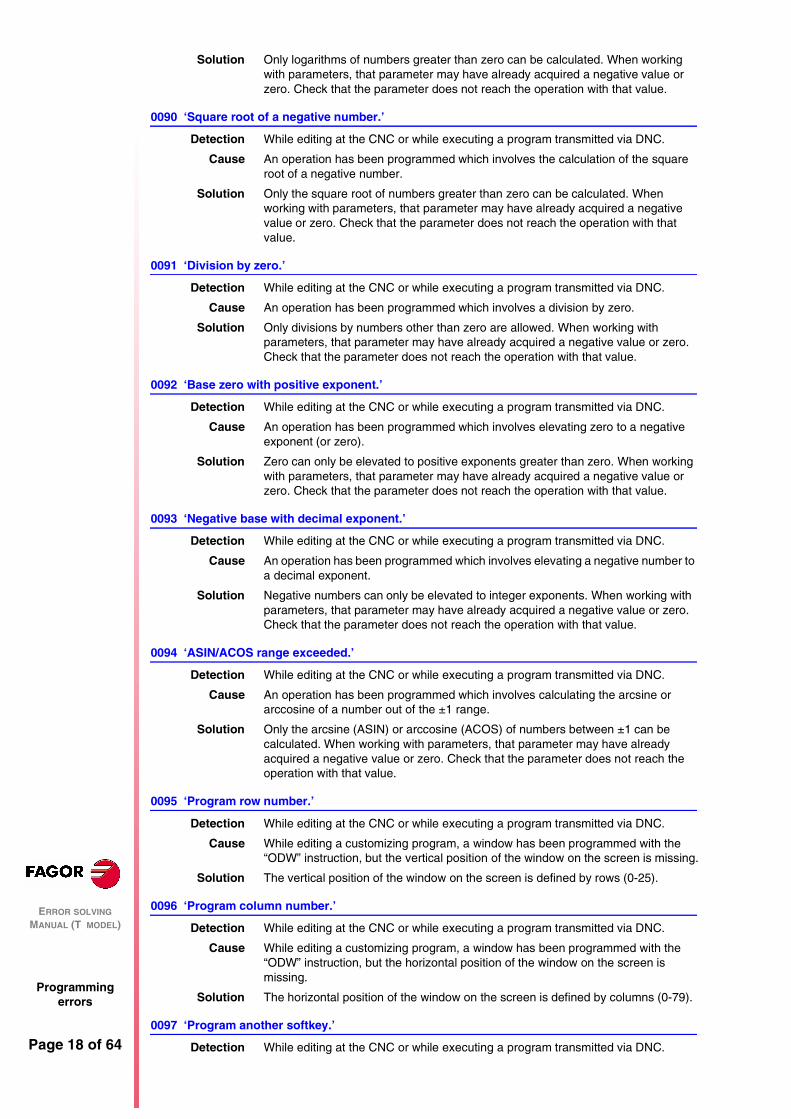
0089 ‘Logarithm of zero or negative number.’
Detection While editing at the CNC or while executing a program transmitted via DNC.
Cause An operation has been programmed which involves the calculation of a negative number or a zero.
Local: 0-25Global: 100-299
Page 18 of 64
ERROR SOLVING MANUAL (T MODEL)
Programming errors
Solution Only logarithms of numbers greater than zero can be calculated. When working with parameters, that parameter may have already acquired a negative value or zero. Check that the parameter does not reach the operation with that value.
0090 ‘Square root of a negative number.’
Detection While editing at the CNC or while executing a program transmitted via DNC.
Cause An operation has been programmed which involves the calculation of the square root of a negative number.
Solution Only the square root of numbers greater than zero can be calculated. When working with parameters, that parameter may have already acquired a negative value or zero. Check that the parameter does not reach the operation with that value.
0091 ‘Division by zero.’
Detection While editing at the CNC or while executing a program transmitted via DNC.
Cause An operation has been programmed which involves a division by zero.
Solution Only divisions by numbers other than zero are allowed. When working with parameters, that parameter may have already acquired a negative value or zero. Check that the parameter does not reach the operation with that value.
0092 ‘Base zero with positive exponent.’
Detection While editing at the CNC or while executing a program transmitted via DNC.
Cause An operation has been programmed which involves elevating zero to a negative exponent (or zero).
Solution Zero can only be elevated to positive exponents greater than zero. When working with parameters, that parameter may have already acquired a negative value or zero. Check that the parameter does not reach the operation with that value.
0093 ‘Negative base with decimal exponent.’
Detection While editing at the CNC or while executing a program transmitted via DNC.
Cause An operation has been programmed which involves elevating a negative number to a decimal exponent.
Solution Negative numbers can only be elevated to integer exponents. When working with parameters, that parameter may have already acquired a negative value or zero. Check that the parameter does not reach the operation with that value.
0094 ‘ASIN/ACOS range exceeded.’
Detection While editing at the CNC or while executing a program transmitted via DNC.
Cause An operation has been programmed which involves calculating the arcsine or arccosine of a number out of the ±1 range.
Solution Only the arcsine (ASIN) or arccosine (ACOS) of numbers between ±1 can be calculated. When working with parameters, that parameter may have already acquired a negative value or zero. Check that the parameter does not reach the operation with that value.
0095 ‘Program row number.’
Detection While editing at the CNC or while executing a program transmitted via DNC.
Cause While editing a customizing program, a window has been programmed with the “ODW” instruction, but the vertical position of the window on the screen is missing.
Solution The vertical position of the window on the screen is defined by rows (0-25).
0096 ‘Program column number.’
Detection While editing at the CNC or while executing a program transmitted via DNC.
Cause While editing a customizing program, a window has been programmed with the “ODW” instruction, but the horizontal position of the window on the screen is missing.
Solution The horizontal position of the window on the screen is defined by columns (0-79).
0097 ‘Program another softkey.’
Detection While editing at the CNC or while executing a program transmitted via DNC.

ERROR SOLVING MANUAL (T MODEL)
Programming errors
Page 19 of 64
Cause While editing a customizing program, the programming format for the “SK” instruction has not been respected.
Solution Correct the syntax of the block. The programming format is:(SK1=(text 1), SK2=(text 2)…)
If the “,” character is entered after a text, the CNC expects the name of another softkey.
0098 ‘Program softkeys 1 thru 7.’
Detection While executing in the user channel.
Cause In the block syntax, a softkey has been programmed out of the 1 to 7 range.
Solution Only softkeys within the 1 to 7 range can be programmed.
0099 ‘Program another window.’
Detection While editing at the CNC or while executing a program transmitted via DNC.
Cause While editing a customizing program, the programming format for the “DW” instruction has not been respected.
Solution Correct the syntax of the block. The programming format is:(DW1=(assignment), DW2=(assignment)…)
If the “,” character is entered after an assignment, the CNC expects the name of another window.
0100 ‘Program windows 0 thru 25.’
Detection While executing in the user channel.
Cause In the block syntax, a window has been programmed out of the 0 to 25 range.
Solution Only windows within the 0 to 25 range can be programmed.
0101 ‘Program rows 0 thru 20.’
Detection While executing in the user channel.
Cause In the block syntax, a row has been programmed out of the 0 to 20 range.
Solution Only rows within the 0 to 20 range can be programmed.
0102 ‘Program columns 0 thru 79.’
Detection While executing in the user channel.
Cause In the block syntax, a column has been programmed out of the 0 to 79 range.
Solution Only columns within the 0 to 79 range can be programmed.
0103 ‘Program pages 0 thru 255.’
Detection While executing in the user channel.
Cause In the block syntax, a page has been programmed out of the 0 to 255 range.
Solution Only pages within the 0 to 255 range can be programmed.
0104 ‘Program INPUT.’
Detection While editing at the CNC or while executing a program transmitted via DNC.
Cause While programming in high level language, an “IB” instruction has been edited without associating an “INPUT” to it.
Solution Remember that the programming formats for this instruction are:(IB (expression) = INPUT “text”, format)(IB (expression) = INPUT “text”)
0105 ‘Program inputs 0 thru 25.’
Detection While executing in the user channel.
Cause In the block syntax, an input has been programmed out of the 0 to 25 range.
Solution Only inputs within the 0 to 25 range can be programmed.
0106 ‘Program numerical format.’
Detection While editing at the CNC or while executing a program transmitted via DNC.
Cause While programming in high level language, an “IB” instruction has been edited with non-numeric format.

Page 20 of 64
ERROR SOLVING MANUAL (T MODEL)
Programming errors
Solution Remember that the programming format for this instruction is:(IB (expression) = INPUT “text”, format)
Where «format» must be a signed number with 6 entire digits and 5 decimals at the most.
If the “,” character is entered after the text, the CNC expects the format.
0107 ‘Do not program formats greater than 6.5 .’
Detection While executing in the user channel.
Cause While programming in high level language, an “IB” instruction has been edited in a format with more than 6 entire digits or more than 5 decimals.
Solution Remember that the programming format for this instruction is:(IB (expression) = INPUT “text”, format)
Where «format» must be a signed number with 6 entire digits and 5 decimals at the most.
0108 ‘This command can only be executed in the user channel.’
Detection During execution.
Cause An attempt has been made to execute a block containing information that can only be executed through the user channel.
Solution There are specific expressions for customizing programs that can only be executed inside the user program.
0109 ‘C. User: do not program geometric help, compensation or cycles.’
Detection While executing in the user channel.
Cause An attempt has been made to execute a block containing geometric aide, tool radius/length compensation or machining canned cycles.
Solution Inside a customizing program the following cannot be programmed:Neither geometric assistance nor movements.Neither tool radius nor length compensation.Canned cycles.
0110 ‘Local parameters not allowed.’
Detection While editing at the CNC or while executing a program transmitted via DNC.
Cause Some functions can only be programmed with global parameters.
Solution Global parameters are the ones included in the 100-299 range.
0111 ‘Block cannot be executed while running another program’
Detection While executing in MDI mode
Cause An attempt has been made to execute a customizing instruction from MDI mode while the user channel program is running.
Solution Customizing instructions can only be executed through the user channel.
0112 ‘WBUF can only be executed in user channel while editing’
Detection During normal execution or execution through the user channel.
Cause An attempt has been made to execute the “WBUF” instruction.
Solution The “WBUF” instruction cannot be executed. It can only be used in the editing stage through the user input.
0113 ‘Table limits exceeded.’
Detection While editing tables.
Cause The various causes might be:1. In the tool offset table, an attempt has been made to define a tool offset with a
greater number than allowed by the manufacturer.2. In the parameter tables, an attempt has been made to define a nonexistent
parameter.
Solution The tool offset number must be smaller than the one allowed by the manufacturer.
0114 ‘Offset: D3 X Z R F I K.’
Detection While editing tables.

ERROR SOLVING MANUAL (T MODEL)
Programming errors
Page 21 of 64
Cause In the tool offset table, the parameter editing order has not been respected.
Solution Enter the table parameters in the right order.
0115 ‘Tool: T4 D3 F3 N5 R5(.2).’
Detection While editing tables.
Cause In the tool table, the parameter editing order has not been respected.
Solution Enter the table parameters in the right order.
0116 ‘Origin: G54-59 axes (1-5).’
Detection While editing tables.
Cause In the Zero offset table, the zero offset to be defined (G54-G59) has not be selected.
Solution Enter the table parameters in the right order. To fill out the zero offset table, first select the offset to be defined (G54-G59) and then the zero offset position for each axis.
0117 ‘Function: M4 S4 bits(8).’
Detection While editing tables.
Cause In the «M» function table, the parameter editing order has not been respected.
Solution Edit table following the format: M1234 (associated subroutine) (customizing bits)
0118 ‘G51 [A] E’
Detection In execution or while executing programs transmitted via DNC.
Cause In the «Look-Ahead (G51)» function, the parameter for the maximum contouring error is missing.
Solution This type of machining requires the programming of:E : Maximum contouring error.
The rest of the parameters are optional. The parameters must be edited in the order indicated by the error message.
0119 ‘Leadscrew: Coordinate-error.’
Detection While editing tables.
Cause In the leadscrew compensation tables, the parameter editing order has not been respected.
Solution Enter the table parameters in the right order.P123 (position of the axis to be compensated) (leadscrew error at that point)
0120 ‘Incorrect axis.’
Detection While editing tables.
Cause In the leadscrew compensation tables, an attempt has been made to edit a different axis from the one corresponding to that table.
Solution Each axis has its own table for leadscrew compensation. The table for each axis can only contain the positions for that axis.
0121 ‘Program P3 = value.’
Detection While editing tables.
Cause In the machine parameter table, the editing format has not been respected.
Solution Enter the table parameters in the right order.P123 = (parameter value)
0122 ‘Magazine: P(1-255) = T(1-9999).’
Detection While editing tables.
Cause In the tool magazine table, the editing format has not been respected or some data is missing.
Solution Enter the table parameters in the right order.
0123 ‘Tool T0 does not exist.’
Detection While editing tables.

Page 22 of 64
ERROR SOLVING MANUAL (T MODEL)
Programming errors
Cause In the tool table, an attempt has been made to edit a tool as T0.
Solution No tool can be edited as T0. The first tool must be T1.
0124 ‘Offset D0 does not exist.’
Detection While editing tables.
Cause In the tool table, an attempt has been made to edit a tool offset as D0.
Solution No tool offset can be edited as D0. The first tool offset must be D1.
0125 ‘Do not modify the active tool or the next one.’
Detection During execution.
Cause In the tool magazine table, an attempt has been made to change the active tool or the next one.
Solution During execution, neither the active tool nor the next one may be changed.
0126 ‘Tool not defined.’
Detection While editing tables.
Cause In the tool magazine table, an attempt has been made to assign to the magazine position a tool that is not defined in the tool table.
Solution Define the tool in the tool table.
0127 ‘Magazine is not RANDOM.’
Detection While editing tables.
Cause There is no RANDOM magazine and, in the tool magazine table, the tool number does not match the tool magazine position.
Solution When the tool magazine is not RANDOM, the tool number must be the same as the magazine position (pocket number).
0128 ‘The position of a special tool is set.’
Detection While editing tables.
Cause In the tool magazine table, an attempt has been made to place a tool in a magazine position reserved for a special tool.
Solution When a special tool occupies more than one position in the magazine, it has a reserved position in the magazine. No other tool can be placed in this position.
0129 ‘Next tool only possible in machining centers.’
Detection During execution.
Cause A tool change has been programmed with M06, but the machine is not a machining center. (it is not expecting the next tool).
Solution When the machining is not a machining center, the tool change is done automatically when programming the tool number «T».
0130 ‘Write 0/1.’
Detection While editing machine parameters
Cause An attempt has been made to assign the wrong value to a parameter.
Solution The parameter only admits values of 0 or 1.
0131 ‘Write +/-.’
Detection While editing machine parameters
Cause An attempt has been made to assign the wrong value to a parameter.
Solution The parameter only admits values of + or -.
0132 ‘Write YES/NO.’
Detection While editing machine parameters
Cause An attempt has been made to assign the wrong value to a parameter.
Solution The parameter only admits values of YES or NO.

ERROR SOLVING MANUAL (T MODEL)
Programming errors
Page 23 of 64
0133 ‘Write ON/OFF.’
Detection While editing machine parameters
Cause An attempt has been made to assign the wrong value to a parameter.
Solution The parameter only admits values of ON or OFF.
0134 ‘Values 0 thru 2.’0135 ‘Values 0 thru 3.’0136 ‘Values 0 thru 4.’0137 ‘Values 0 thru 9.’0138 ‘Values 0 thru 29.’0139 ‘Values 0 thru 100.’0140 ‘Values 0 thru 255.’0141 ‘Values 0 thru 9999.’0142 ‘Values 0 thru 32767.’0143 ‘Values within +/-32767.’0144 ‘Values 0 thru 65535.’
Detection While editing machine parameters
Cause The various causes might be:1. An attempt has been made to assign the wrong value to a parameter.2. During execution, when inside the program a call has been made to a
subroutine (MCALL, PCALL) with a value greater than allowed.
0145 ‘Format +/- 5.5.’
Detection While editing machine parameters
Cause An attempt has been made to assign the wrong value to a parameter.
Solution The parameter only admits values with the format:
0146 ‘Word does not exist.’
No explanation required
0147 ‘Numerical format exceeded.’
Detection While editing at the CNC or while executing a program transmitted via DNC.
Cause A data or parameter has been assigned a value greater than the established format.
Solution Correct the syntax of the block. Most of the time, the numeric format will be 5.4 (5 integers and 4 decimals).
0148 ‘Text too long.’
Detection While editing at the CNC or while executing a program transmitted via DNC.
Cause While programming in high level language, the “ERROR” or “MSG” instruction has been assigned a text with more than 59 characters.
Solution Correct the syntax of the block. The “ERROR” and “MSG” instructions cannot be assigned texts longer than 59 characters.
0149 ‘Incorrect message.’
Detection While editing at the CNC or while executing a program transmitted via DNC.
Cause While programming in high level language, the text associated with the “ERROR” or “MSG” instruction has been edited wrong.
Solution Correct the syntax of the block. The programming format is:(MSG “message”)(ERROR number, “message”)
The message must be between “ ”.
0150 ‘Incorrect number of bits.’
Detection While editing tables.
Cause The various causes might be:1. In the «M» function table, in the section on customizing bits:
The number does not have 8 bits.The number does not consist of 0’s and 1’s.

Page 24 of 64
ERROR SOLVING MANUAL (T MODEL)
Programming errors
2. In the machine parameter table, an attempt has been made to assign the wrong value of bit to a parameter.
Solution The solution for each cause is:1. The customizing bits must consist of 8 digits of 0’s and 1’s.2. The parameter only admits 8-bit or 16-bit numbers.
0151 ‘Negative numbers not allowed.’
No explanation required
0152 ‘Incorrect parametric programming.’
Detection During execution.
Cause The parameter has a value that is incompatible with the function it has been assigned to.
Solution This parameter may have taken the wrong value, in the program history. Correct the program so this parameter does not reach the function with that value.
0153 ‘Decimal format not allowed.’
No explanation required
0154 ‘Insufficient memory.’
Detection During execution.
Cause The CNC does not have enough memory to internally calculate the paths.
Solution Sometimes, this error is taken care of by changing the machining conditions.
0155 ‘Help not available.’
No explanation required
0156 ‘Don’t program G33 ,G34, G95 or M19 S with no spindle encoder’
Detection While editing at the CNC or while executing a program transmitted via DNC.
Cause A “G33”, “G34”, “G95”, “G95” or “M19 S” has been programmed without having an encoder on the spindle.
Solution If the spindle does not have an encoder, functions “M19 S”, “G33”, “G34” or “G95” cannot be programmed. Spindle machine parameter “NPULSES (P13)” indicates the number of encoder pulses per turn.
0159 ‘Inch programming limit exceeded.’
Detection During execution.
Cause An attempt has been made to execute in inches a program edited in millimeters.
Solution Enter function G70 (inch programming) or G71 (mm programming) at the beginning of the program.
0162 ‘No negative radius allowed with absolute coordinates’
Detection During execution.
Cause While operating with absolute polar coordinates, a movement with a negative radius has been programmed.
Solution Negative radius cannot be programmed when using absolute polar coordinates.
0164 ‘Wrong password.’
Detection While assigning protections.
Cause [ENTER] has been pressed before selecting the type of code to be assigned a password.
Solution Use the softkeys to select the type of code to which a password is to be assigned.
0165 ‘Password: use uppercase/lowercase letters or digits.’
Detection While assigning protections.
Cause A bad character has been entered in the password.
Solution The password can only consist of letters (upper and lower case) or digits.

ERROR SOLVING MANUAL (T MODEL)
Programming errors
Page 25 of 64
0166 ‘Only one HIRTH axis per block is allowed.’
Detection While editing at the CNC or while executing a program transmitted via DNC.
Cause A movement has been programmed which involves the movement of two HIRTH axes simultaneously.
Solution The CNC does not admit movements involving more than one HIRTH axis at a time. HIRTH axes must move one at a time.
0167 ‘Rot. axis position: absolute values (G90) within 0-359.9999.’
Detection During execution.
Cause A movement of a positioning-only rotary axis has been programmed. The movement has been programmed in absolute coordinates (G90) and the target coordinate of the movement is not within the 0 to 359.9999 range.
Solution Positioning-only rotary axes: In absolute coordinates, only movements within the 0 to 359.9999 range are possible.
0168 ‘Rotary axis: absolute values (G90) within 0-359.9999.’
Detection During execution.
Cause A movement of a rotary axis has been programmed. The movement has been programmed in absolute coordinates (G90) and the target coordinate of the movement is not within the 0 to 359.9999 range.
Solution Rotary axes: In absolute coordinates, only movements within the 0 to 359.9999 range are possible.
0169 ‘Modal subroutines cannot be programmed.’
Detection While executing in MDI mode
Cause An attempt has been made to call upon a modal subroutine (MCALL).
Solution MCALL modal subroutines cannot be executed from the menu option «MDI execution».
0170 ‘Program symbols 0 thru 255 in positions 0-639, 0-335. ‘
No explanation required
0171 ‘The window must be previously defined.’
Detection During normal execution or execution through the user channel.
Cause An attempt has been made to write in a window (DW) that has not been previously defined (ODW).
Solution It is not possible to write in a window that has not been previously defined. Check that the window to write in (DW) has been previously defined.
0172 ‘The program is not accessible’
Detection During execution.
Cause An attempt has been made to execute a program that cannot be executed.
Solution The program may be protected against execution. To know whether a program may be executed, check for the “X” character on the attributes column. If this character is missing, the program cannot be executed.
0173 ‘It is not possible to program angle + angle.’
No explanation required
0174 ‘Circular (helical) interpolation not possible.’
Detection During execution.
Cause An attempt has been made to execute a helical interpolation while the «LOOK-AHEAD (G51)» function was active.
Solution Helical interpolations are not possible while the «LOOK-AHEAD (G51)» function is active.
0175 ‘Analog inputs: ANAI(1-8) = +/-5 Volts.’
Detection During execution.
Cause An analog input has taken a value out of the ±5V range.

Page 26 of 64
ERROR SOLVING MANUAL (T MODEL)
Programming errors
Solution Analog inputs may only take values within the ±5V range.
0176 ‘Analog outputs: ANAO(1-8) = +/-10 Volts.’
Detection During execution.
Cause An analog output has been assigned a value out of the ±10V range.
Solution Analog outputs may only take values within the ±10V range.
0177 ‘A gantry axis cannot be part of the active plane.’
No explanation required
0178 ‘G96 only possible with analog spindle.’
Detection During execution.
Cause The “G96” function has been programmed but either the spindle speed is not controlled or the spindle does not have an encoder.
Solution To operate with the “G96” function, the spindle speed must be controlled (SPDLTYPE(P0)=0) and the spindle must have an encoder (NPULSES(P13) other than zero).
0179 ‘Do not program more than 4 axes simultaneously.’
No explanation required
0180 ‘Program DNC1/2, HD or CARD A (optional).’
Detection While editing or executing.
Cause While programming in high level language, in the “OPEN” and “EXEC” instructions, an attempt has been made to program a parameter other than DNC1/2, HD or CARD A, or the DNC parameter has been assigned a value other than 1 or 2.
Solution Check the syntax of the block.
0181 ‘Program A (append) or D (delete).’
Detection While editing at the CNC or while executing a program transmitted via DNC.
Cause In the “OPEN” instruction the A/D parameter is missing.
Solution Check the syntax of the block. The programming format is:(OPEN P———,A/D,… )
Where:
0182 ‘Option not available.’
Detection While editing at the CNC or while executing a program transmitted via DNC.
Cause A «G» function has been defined which is not a software option.
0184 ‘T with subroutine: program only T and D.’
No explanation required
0185 ‘Tool offset does not exist’
Detection While editing at the CNC or while executing a program transmitted via DNC.
Cause Within the block syntax, a tool offset has been called upon which is greater than the ones allowed by the manufacturer.
Solution Program a new smaller tool offset.
0186 ‘The “C” axis does not exist.’
Detection While editing at the CNC or while executing a program transmitted via DNC.
Cause An attempt has been made to activate the “C” axis, but the machine does not have this feature.
0187 ‘G66, G68, G69 are not allowed when machining with the “C” axis.’
Detection During execution.
Cause An attempt has been made to execute a “G66”, “G67” or “G68” canned cycle while the “C” axis is active.
A Appends new blocks after the existing ones.D: Deletes the existing program and it opens it as a new one.
ERROR SOLVING MANUAL (T MODEL)
Programming errors
Page 27 of 64
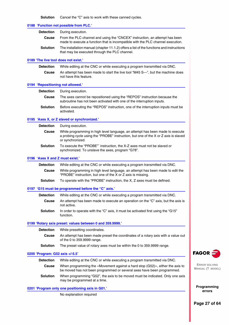
Solution Cancel the “C” axis to work with these canned cycles.
0188 ‘Function not possible from PLC.’
Detection During execution.
Cause From the PLC channel and using the “CNCEX” instruction, an attempt has been made to execute a function that is incompatible with the PLC channel execution.
Solution The installation manual (chapter 11.1.2) offers a list of the functions and instructions that may be executed through the PLC channel.
0189 ‘The live tool does not exist.’
Detection While editing at the CNC or while executing a program transmitted via DNC.
Cause An attempt has been made to start the live tool “M45 S—”, but the machine does not have this feature.
0194 ‘Repositioning not allowed.’
Detection During execution.
Cause The axes cannot be repositioned using the “REPOS” instruction because the subroutine has not been activated with one of the interruption inputs.
Solution Before executing the “REPOS” instruction, one of the interruption inputs must be activated.
0195 ‘Axes X, or Z slaved or synchronized.’
Detection During execution.
Cause While programming in high level language, an attempt has been made to execute a probing cycle using the “PROBE” instruction, but one of the X or Z axis is slaved or synchronized.
Solution To execute the “PROBE”¨ instruction, the X-Z axes must not be slaved or synchronized. To unslave the axes, program “G78”.
0196 ‘Axes X and Z must exist.’
Detection While editing at the CNC or while executing a program transmitted via DNC.
Cause While programming in high level language, an attempt has been made to edit the “PROBE” instruction, but one of the X or Z axis is missing.
Solution To operate with the “PROBE” instruction, the X, Z axes must be defined.
0197 ‘G15 must be programmed before the “C” axis.’
Detection While editing at the CNC or while executing a program transmitted via DNC.
Cause An attempt has been made to execute an operation on the “C” axis, but the axis is not active.
Solution In order to operate with the “C” axis, it must be activated first using the “G15” function.
0199 ‘Rotary axis preset: values between 0 and 359.9999.’
Detection While presetting coordinates.
Cause An attempt has been made preset the coordinates of a rotary axis with a value out of the 0 to 359.9999 range.
Solution The preset value of rotary axes must be within the 0 to 359.9999 range.
0200 ‘Program: G52 axis +/-5.5’
Detection While editing at the CNC or while executing a program transmitted via DNC.
Cause When programming the «Movement against a hard stop (G52)», either the axis to be moved has not been programmed or several axes have been programmed.
Solution When programming “G52”, the axis to be moved must be indicated. Only one axis may be programmed at a time.
0201 ‘Program only one positioning axis in G01.’
No explanation required

Page 28 of 64
ERROR SOLVING MANUAL (T MODEL)
Programming errors
0206 ‘Values 0 thru 6.’
Detection While editing machine parameters
Cause An attempt has been made to assign the wrong value to a parameter.
Solution The parameter only admits values between 0 and 6.
0207 ‘Complete Table.’
Detection While editing tables.
Cause In the tables for «M» functions or tool offsets, an attempt has been made to define more data than those allowed by the manufacturer by means of machine parameters. When loading a table via DNC, the CNC does not delete the previous table, it replaces the existing values and it copies the new data in the free positions of the table.
Solution The maximum number of data that can be defined is limited by the machine parameters:
To load a new table via DNC, the previous table should be deleted.
0208 ‘Program A from 0 to 255’
Detection During execution.
Cause In the «LOOK-AHEAD (G51)» function, parameter “A” (% of acceleration to be applied) has been programmed with a value greater than 255.
Solution Parameter “A” is optional, but when programmed, it must have a value between 0 and 255.
0209 ‘Program nesting not allowed.’
Detection During execution.
Cause From a running program, an attempt has been made to execute another program with the “EXEC” instruction which in turn also has an “EXEC” instruction.
Solution Another program cannot be called upon from a program being executed using the “EXEC” instruction.
0210 ‘No compensation is permitted.’
Detection While editing at the CNC or while executing a program transmitted via DNC.
Cause An attempt has been made to activate or cancel tool radius compensation (G41, G42, G40) in a block containing a nonlinear movement.
Solution Tool radius compensation must be activated/deactivated in linear movements (G00, G01).
0213 ‘A second spindle is required for G28, G29, G77 or G78.’
Detection While editing at the CNC or while executing a program transmitted via DNC.
Cause An attempt has been made to select the work spindle with “G28/G29” or synchronize spindles with “G77/G78”, but the machine only has one work spindle.
Solution If the machine only has one work spindle, the “G28, G29, G77 and G78” functions cannot be programmed.
0214 ‘Invalid G function when selecting a profile’
Detection While restoring a profile.
Cause Within the group of blocks selected to restore the profile, there is a block containing a «G» code that does not belong in the profile definition.
Solution The «G» functions available in the profile definition are:
0215 ‘Invalid G function after first point of profile’
Detection While restoring a profile.
Maximum number of «M» functions NMISCFUN(P29).Maximum number of NTOOL(P23).Maximum number of tool offset NTOFFSET(P27).Maximum number of magazine positions NPOCKET(P25).
G00 G01 G02 G03 G06 G08 G09G36 G37 G38 G39 G90 G91 G93

ERROR SOLVING MANUAL (T MODEL)
Programming errors
Page 29 of 64
Cause Within the selected blocks for restoring the profile, and after the starting point of a profile, there is a block containing a «G» function that does not belong in the profile definition.
Solution The «G» functions available in the profile definition are:
0216 ‘Nonparametric assignment after first point of profile’
Detection While restoring a profile.
Cause Within the selected blocks for restoring the profile, and after the starting point of a profile, a nonparametric assignment has been programmed in high level language (a local or global parameter).
Solution The only high level instructions that can be edited are assignments to local parameters (P0 thru P25) and global parameters (P100 thru P299).
0217 ‘Invalid programming after first point of profile’
Detection While restoring a profile.
Cause Within the selected blocks for restoring the profile, and after the starting point of a profile, there is a high level block that is not an assignment.
Solution The only high level instructions that can be edited are assignments to local parameters (P0 thru P25) and global parameters (P100 thru P299).
0218 ‘The axis cannot be programmed after first point of profile’
Detection While restoring a profile.
Cause Within the selected blocks for restoring the profile, and after the starting point of a profile, a position has been defined on an axis that does not belong to the active plane. A surface coordinate may have been defined after the starting point of the profile.
Solution The surface coordinate of the profiles is only defined in the starting block of the first profile, the one corresponding to the starting point of the outside profile.
0219 ‘First point programmed wrong when selecting profile’
Detection While selecting a profile.
Cause The starting point of the profile has been programmed wrong. One of the two coordinates defining its position is missing.
Solution The starting point of a profile must be defined on the two axes forming the active plane.
0227 ‘Program Q between +/-359.9999.’
Detection While editing at the CNC or while executing a program transmitted via DNC.
Cause In the «Electronic threading (G33)» function, the entry angle “Q” has been programmed with a value out of the ±359.9999 range.
Solution Program an entry angle within the ±359.9999 range.
0228 ‘Do not program "Q" with parameter M19TYPE=0.’
Detection While editing at the CNC or while executing a program transmitted via DNC.
Cause In the «Electronic threading (G33)» function, an entry angle “Q” has been programmed, but the type of spindle orientation available does not allow this operation.
Solution In order to define an entry angle, spindle machine parameter M19TYPE(P43) must be set to «1».
0229 ‘Program maximum Z’0230 ‘Program inside R’0231 ‘Program outside R’
Detection While editing at the CNC or while executing a program transmitted via DNC.
Cause While programming in high level language, in the “DGWZ” instruction, the indicated limit is missing or it has been defined with a non-numerical value.
Solution Check the syntax of the block.
G00 G01 G02 G03 G06 G08 G09G36 G37 G38 G39 G90 G91 G93

Page 30 of 64
ERROR SOLVING MANUAL (T MODEL)
Programming errors
0234 ‘Wrong graphic limits’
Detection During execution.
Cause One of the lower limits defined with the “DGWZ” instruction is greater than its corresponding upper limit.
Solution Program the upper limit of the graphics display area greater than the lower ones.
0235 ‘Do not program the axis in tangential control’
No explanation required
0236 ‘Do not program the longitudinal axis or the axis of the active plane’
No explanation required
0237 ‘Program values between +/-359.9999.’
Detection During execution.
Cause A G30 offset has been programmed greater than the maximum allowed. For example G30 D380
Solution The offset must be within ±359.9999.
0238 ‘Do not program G30 without synchronizing the spindles in speed’
Detection During execution.
Cause An attempt has been made to synchronize the spindles in “G30” offset without having them synchronized in speed.
Solution First, synchronize the spindle in speed using G77S.
0239 ‘Do not synchronize the spindles while the “C” axis is active’
Detection During execution.
Cause An attempt has been made to synchronize the spindle, but the “C” axis is not active.
Solution Activate the “C” axis first.
0240 ‘Do not activate the “C” axis while the spindles are synchronized’
Detection During execution.
Cause An attempt has been made to activate the “C” axis while the spindles were synchronized.
Solution First, cancel the spindle synchronization (G78 S).
0241 ‘Do not program G77 S, G78 S if there is no encoder at the spindle’
Detection During execution.
Cause An attempt has been made to synchronize the spindles (G77 S or G78 S) and one of them does not have an encoder or Sercos feedback.
Solution Both spindles must have an encoder or Sercos feedback.
0242 ‘Do not synchronize spindles with M19TYPE=0’
Detection During execution.
Cause An attempt has been made to synchronize the spindles (G77 S or G78 S) and one of them has parameter M19TYPE=0.
Solution Both spindles must have parameter M19TYPE=1

ERROR SOLVING MANUAL (T MODEL)
Block preparation and execution errors
Page 31 of 64
BLOCK PREPARATION AND EXECUTION ERRORS
1000 ‘There is no enough path information.’
Detection During execution.
Cause The program contains too many blocks without information about the path to apply tool radius compensation, rounding, chamfer or tangential entry or exit.
Solution In order to carry out these operations, the CNC needs to know in advance the path to follow; therefore, there cannot be more than 48 blocks in a row without information about the path to follow.
1001 ‘Plane change in rounding/chamfering.’
Detection During execution.
Cause A plane change has been programmed on the path following the definition of a “controlled corner rounding G36” or “chamfer (G39)”.
Solution The plane cannot be changed while executing a rounding or a chamfer. The path following the definition of a rounding or chamfer must be in the same plane that the rounding or the chamfer.
1002 ‘Rounding radius too large.’
Detection During execution.
Cause In the “Controlled corner rounding (G36)” function, the programmed rounding radius is larger than one of the paths where it has been defined.
Solution The rounding radius must be smaller than the paths that define it.
1003 ‘Rounding in last block.’
Detection During execution.
Cause A “Controlled rounding radius (G36) or “Chamfer (G39) has been defined on the last path of the program or when the CNC does not find information about the path following the definition of the rounding or chamfer.
Solution A rounding or chamfer must be defined between two paths.
1004 ‘Tangential output programmed wrong’
Detection During execution.
Cause The move following the definition of a tangential output (G38) is a circular path.
Solution The move following the definition of a tangential output must be a straight path.
1005 ‘Chamfer programmed wrong.’
Detection During execution.
Cause The move following the definition of a “Chamfer (G39)” is a circular path.
Solution The move following the definition of a chamfer must be a straight path.
1006 ‘Chamfer value too large.’
Detection During execution.
Cause In the “Chamfer (G39)” function, the programmed chamfer value is larger than one of the paths where it has been defined.
Solution The chamfer size must be smaller than the paths that define it.
1007 ‘G8 defined wrong.’
Detection During execution.
Cause The various causes might be:1. When a full circle has been programmed using the function “Arc tangent to
previous path (G08)”2. When the tangent path ends in a point of the previous path or its extension (in
a straight line).3. In an irregular pocket canned cycle with islands, when programming function
“G08” in the block following the definition of the beginning of the profile (G00).
Solution The solution for each cause is:

Page 32 of 64
ERROR SOLVING MANUAL (T MODEL)
Block preparation and execution errors
1. Function “G08” does not allow programming full circles.
2. Tangent path must not end in a point of the previous path or in its extension (in a straight line).
3. The CNC does not have information about the previous path and cannot execute the tangent arc.
1008 ‘There is no information about the previous path’
Detection During execution.
Cause An arc tangent to the previous path has been programmed using function “G08”, but there is no information about the previous path.
Solution To do a path tangent to the previous one, there must be information about the previous path and it must be within the 48 blocks preceding the tangent path.
1010 ‘Wrong plane for tangent path.’
Detection During execution.
Cause A plane change has been programmed between the definition of the function “arc tangent to previous path (G08)” and the previous path.
Solution A plane cannot be changed between two paths
1011 ‘No radius has been programmed for G15.’
Detection During execution.
Cause The Z-C plane has been selected as a new work plane, but the radius of the cylinder to be machined has not been defined.
Solution In order to work in the Z-C plane, first define the radius of the cylinder on which to machine using function “G15 R—”.
1015 ‘The tool is not defined in the tool table’
Detection During execution.
Cause A tool change has been defined, but the new tool is not defined in the tool table.
Solution Define the new tool in the tool table.
1016 ‘The tool is not in the tool magazine’
Detection During execution.
Cause A tool change has been defined, but the new tool is not defined in position of the tool magazine table.
Solution Define the new tool in the tool magazine table.
1017 ‘There is no empty pocket in the tool magazine’
Detection During execution.
Cause A tool change has been defined and there is no empty pocket for the tool that is currently in the spindle.
Solution Perhaps, the new tool has been defined as special in the tool table and there are more than one pockets reserved to it in the magazine. In this case, that position is set for that tool and no other tool can occupy it. To avoid this error, an empty pocket (position) should be left in the tool magazine.
1018 ‘A tool change has been programmed without M06’
Detection During execution.
Cause An M06 has not been programmed after having looked for a tool and before searching again.
Solution This error occurs when having a machining center (general machine parameter TOFFM06(P28)=YES) that has a cyclic tool changer (general machine parameter CYCATC(P61)=YES). In this case, the tool change must be done with an m06 after searching for a tool and before searching for the next one.
1019 ‘There is no tool of the same family for replacement.’
Detection During execution.
Cause The real life of the requested tool exceeds its nominal life. The CNC has tried to replace it with another one of the same family, but it has not found any.

ERROR SOLVING MANUAL (T MODEL)
Block preparation and execution errors
Page 33 of 64
Solution Replace the tool or define another one of the same family.
1020 ‘Do not change the active or pending tool using high level language.’
Detection During execution.
Cause While programming in high level language and using the “TMZT” variable, an attempt has been made to assign the current or next tool to a magazine position.
Solution Use the “T” function to change the active tool or the next one. The “TMZT” variable cannot be used to move the active tool or the next one to the magazine.
1021 ‘No tool offset has been programmed in the canned cycle.’
Detection During execution.
Cause The “PROBE” canned cycle for tool calibration has been programmed, but no tool offset has been selected.
Solution To execute the “Tool calibration canned cycle (PROBE), a tool offset must be selected where the probing cycle information will be stored.
1022 ‘Tool radius programmed incorrectly’
No explanation required
1028 ‘Do not switch axes over or back while G15 is active’
Detection During execution.
Cause An attempt has been made to switch over to an axis or back (G28/G29) while function “G15” was active.
1029 ‘Do not swap axes that are already swapped.’
Detection During execution.
Cause An attempt has been made to swap (G28) an axis that was already swapped with another one.
Solution An axis already swapped with another one cannot be swapped with a third one. It must be switched back first (G29 axis)
1030 ‘The “M” for the automatic gear change does not fit’
Detection During execution.
Cause Using automatic gear change, 7 “M” functions and the “S” function (involving a gear change) have been programmed. In this case, the CNC cannot include the “M” for automatic gear change in that block.
Solution Program an “M” function or the “S” function in a separate block.
1031 ‘No subroutine is allowed with automatic gear change.’
Detection During execution.
Cause On machines having an automatic gear change, when programming a spindle speed “S” that involves a gear change and the “M” function of the automatic gear change has a subroutine associated with it.
Solution When having an automatic gear change, the “M” functions corresponding to the gear change cannot have a subroutine associated with it.
1032 ‘Spindle gear (range) not defined in M19.’
Detection During execution.
Cause “M19” has been programmed, but none of the gear change functions “M41”, “M42”, “M43” or “M44” are active.
Solution On power-up, the CNC does not assume any range; Therefore, if the gear change function is not generated automatically (spindle parameter AUTOGEAR(P6)=NO), the auxiliary gear change functions (“M41”, “M42”, “M43” or “M44”) must be programmed.
1033 ‘Wrong gear change.’
Detection During execution.
Cause The various causes might be:1. When trying to make a gear change and the machine parameters for gears
(MAXGEAR1, MAXGEAR2, MAXGEAR3, or MAXGEAR4) are set wrong. All

Page 34 of 64
ERROR SOLVING MANUAL (T MODEL)
Block preparation and execution errors
the gears (ranges) have not been used and the unused ones have been set to a maximum speed of zero rpm.
2. When programming a gear change (“M41”, “M42”, “M43” or “M44”) and the PLC has not responded with the relevant active gear signal (GEAR1, GEAR2, GEAR3 or GEAR4).
Solution The solution for each cause is:1. When not using all four gears, the lower ones must be used starting with
“MAXGEAR1” and the unused gears must be assigned the value of the highest one used.
2. Check the PLC program.
1034 ‘”S” has been programmed, but no gear is active.’
Detection During execution.
Cause An attempt has been made to start the spindle, but no gear is selected.
Solution On power-up, the CNC does not assume any range; Therefore, when programing a spindle speed and the gear change function is not generated automatically (spindle parameter AUTOGEAR(P6)=NO), the auxiliary gear change functions (“M41”, “M42”, “M43” or “M44”) must be programmed.
1035 ‘Programmed “S” too high’
Detection During execution.
Cause An “S” has been programmed with a higher value than allowed by the last active gear.
Solution Program a lower spindle speed “S” .
1036 ‘”S” has not been programmed in G95 or in threading’
Detection During execution.
Cause “mm(inches)/revolution (G95)” or “electronic threading (G33)”has been programmed, but no spindle speed has been selected.
Solution An “S” must be programmed to work in mm/rev (G95) or for an electronic threading (G33).
1037 ‘No “S” has been programmed for G96.’
Detection During execution.
Cause The “Constant Surface Speed (G96)” function has been programmed, but no cutting speed has been defined, a previous one does not exist or no spindle range (gear) is selected.
Solution In order to work at constant surface speed (G96), a cutting speed “S” must be already programmed and a spindle range must be active.
1038 ‘The spindle has not been oriented’
Detection During execution.
Cause An attempt has been made to execute a threading cycle (G86 or G87) as a thread repair without already having oriented the active spindle (main or secondary).
1039 ‘No “F” has been programmed in G94.’
Detection During execution.
Cause An attempt has been made to execute a live tool cycle (G60, G61, G62 and G63) and there is feedrate selected in G94 (mm/min).
Solution First, select the feedrate “F” in mm/min (G94).
1040 ‘Canned cycle does not exist’
Detection While executing in MDI mode
Cause When trying to execute a canned cycle (G8x) after interrupting a program during the execution of a canned cycle (G8x) and then changing the plane.
Solution Do not interrupt the program while executing a canned cycle.
1042 ‘Wrong parameter value in canned cycle’
Detection During execution.

ERROR SOLVING MANUAL (T MODEL)
Block preparation and execution errors
Page 35 of 64
Cause When defining a canned cycle, a parameter has been defined with the wrong value. Perhaps, a parameter that only takes positive values has been assigned a negative value (or zero).
Solution Correct the definition of parameters:• In the “Pattern repeat cycle”:
- Parameter “C” only takes positive values greater than zero.- Parameter “A” only admits values of 0 or 1.- Parameter “J” only takes positive values greater than zero.
• In the canned cycle for “roughing along the Z axis” or “roughing along the X axis”, parameter “C” only takes positive values greater than zero.
• In the “ Axial drilling/tapping canned cycle”:- Parameter “I” only admits values other than zero.- Parameter “B” only takes positive values or zero.
• In the canned cycle for “facing curved sections” or “turning curved sections”, parameter “C” only takes positive values greater than zero.
• In the “Face threading canned cycle” or “Longitudinal threading canned cycle”, parameter “I”, “B”, “E” or “C” has been defined with a zero value.
• In the canned cycle for “grooving along the Z axis” or “grooving along the X axis”, parameter “C” only takes positive values greater than zero.
• In the canned cycle for “Face drilling/tapping” or “Longitudinal drilling/tapping”:- Parameter “I” only admits values other than zero.- Parameter “B” only takes positive values or zero.- Parameter “J” only takes positive values greater than zero.
• In the canned cycle for “slot milling on the face” or “slot milling on the side”, the slot dimension cannot be zero and parameters “I” and “J” only take positive values greater than zero.
1043 ‘Wrong tool for programmed profile.’
Detection During execution.
Cause The selected tool cannot machine anywhere on the profile.
Solution Choose a more appropriate tool to machine the profile.
1044 ‘A profile has been programmed that intersects itself.’
Detection During execution.
Cause In the set of profiles, there is one that intersects itself.
Solution Check the definition of the profiles. A profile cannot intersect itself.
1045 ‘Wrong cutter geometry angle.’
Detection During execution.
Cause The cutter’s geometry angles have been assigned a wrong value.
Solution Correct the tool geometry data.
1046 ‘Wrong tool position before the canned cycle’
Detection During execution.
Cause The canned cycle calling point is defined wrong.
Solution The canned cycle calling point must be off the part and at a distance greater than the one defined as finishing stock on both axes. (Cycles that do not have a finishing stock will use the safety distance).
1047 ‘Wrong location code in canned cycle’
Detection During execution.
Cause The location code (shape) of the tool is not the right one.
Solution Choose a tool with the right location code (shape).
1048 ‘Wrong cutter width’
Detection During execution.
Cause A grooving operation has been defined with a cutter of zero width.
Solution Check the definition of the cutter dimensions (NOSEW). The cutter width must be other than zero.

Page 36 of 64
ERROR SOLVING MANUAL (T MODEL)
Block preparation and execution errors
1049 ‘Incompatible tool position and location code in profile cycle.
Detection During execution.
Cause The canned cycle calling point is defined wrong or the tool location code (shape) is the right one to execute the machining operation.
Solution The canned cycle calling point must be off the part and at a distance greater than the one defined as finishing stock on both axes. Besides, the tool’s location code must allow executing the profile without running into the part.
1050 ‘Wrong value to be assigned to a variable’
Detection During execution.
Cause Using parameters, the value assigned to a variable is too high.
Solution Check the program history to make sure that this parameter does not have that value when it reaches the block where this assignment is made.
1051 ‘Wrong access to PLC variable.’
Detection During execution.
Cause From the CNC, an attempt has been made to read a PLC variable that is not defined in the PLC program.
1052 ‘Access to a variable with wrong index’
Detection During editing
Cause While programming in high level language, an operation has been carried out either with a local parameter greater than 25 or with a global parameter greater 299.
Solution The parameters used by the CNC are:
Other parameters out of these ranges cannot be used in operations.
1053 ‘Local parameters not accessible’
Detection While executing in the user channel.
Cause An attempt has been made to execute a block with an operation that uses local parameters.
Solution The program that is executed in the user channel does not allow operations with local parameters (P0 to P25).
1054 ‘Limit of local parameters exceeded’
Detection During execution.
Cause While programming in high level language, more than 6 nesting levels have been used with the “PCALL” instruction. More than 6 calls have been made in the same loop using the “PCALL” instruction.
Solution Only up to 6 nesting levels are allowed for local parameters within the 15 nesting levels of the subroutines. Calling with a “PCALL” instruction generates a new nesting level for local parameters (and a new one for subroutines).
1055 ‘Nesting exceeded’
Detection During execution.
Cause While programming in high level language, more than 15 nesting levels have been used with the “CALL”, “PCALL” or “MCALL” instruction. More than 15 calls have been made in the same loop using the “CALL”, “PCALL” or “MCALL” instruction.
Solution Only 15 nesting levels allowed. Calling with the “CALL”, “PCALL” and “MCALL” instructions generates a new nesting level.
1056 ‘RET not associated with subroutine.’
Detection During execution.
Cause The “RET” instruction has been edited, but the “SUB” instruction has not been edited before.
Solution To using the “RET” instruction (subroutine), the subroutine must begin with the “SUB (subroutine number)”.
Local: 0-25.Global: 100-299.

ERROR SOLVING MANUAL (T MODEL)
Block preparation and execution errors
Page 37 of 64
1057 ‘Undefined subroutine’
Detection During execution.
Cause A (CALL, PCALL…) has been made to a subroutine that was not defined in the CNC memory.
Solution Check that the name of the subroutine is correct and that the subroutine exists in the CNC memory (not necessarily in the same program where the call is).
1058 ‘Undefined probing canned cycle’
Detection During execution.
Cause Using the “PROBE” instruction, a probing cycle has been defined which is not available.
Solution The available “PROBE” canned cycles are 1 to 4.
1059 ‘Jump to an undefined label’
Detection During execution.
Cause While programming in high level language, the “GOTO N—” instruction has been programmed, but the programmed block number (N) does not exist.
Solution When programming the “GOTO N—” instruction, the block it refers to must be defined in the same program.
1060 ‘Undefined label’
Detection During execution.
Cause The various causes might be:1. While programming in high level language, the instrucción “RPT N—, N—”
instruction has been programmed, but a programmed block number (N) does not exist.
2. In the “Pattern repeat canned cycle (G66)”, “Roughing canned cycle along the X axis (G68)” or “Roughing canned cycle along the Z axis (G69)” a profile definition has been programmed, but one of the two data defining the beginning “S” or end “E” of the profiles is missing.
Solution The solution for each cause is:1. When programming the “RPT N—, N—” instruction, the blocks it refers to must
be defined in the same program.2. Check the program. Place the label for parameter “S” at the beginning of the
profile definition and the label for parameter “E” at the end of the profile definition.
1061 ‘Label cannot be searched’
Detection While executing in MDI mode
Cause While programming in high level language, either an “RPT N—, N—” or “GOTO N—” instruction has been defined.
Solution While operating in MDI mode, “RPT” or “GOTO” type instructions cannot be programmed.
1062 ‘Subroutine in an unavailable program.’
Detection During execution.
Cause A call has been made to a subroutine that it is located in a program being used by the DNC.
Solution Wait for the DNC to finish using the program. If the subroutine is to be used often, it should be stored in a separate program.
1063 ‘The program cannot be opened.’
Detection During execution.
Cause While executing a program in infinite mode, an attempt has been made to execute another infinite program from the current one using the “EXEC” instruction.
Solution Only one infinite program may be executed at a time.
1064 ‘The program cannot be executed’
Detection During execution.

Page 38 of 64
ERROR SOLVING MANUAL (T MODEL)
Block preparation and execution errors
Cause An attempt has been made to execute a program from another with the “EXEC” instruction, but the program does not exist or is protected against execution.
Solution The program to be executed with the “EXEC” instruction must exist in the CNC memory and must be executable.
1065 ‘Beginning of compensation without straight path’
Detection During execution.
Cause The first movement in work plane after activating tool radius compensation (G41/G42) is not a linear movement.
Solution The first movement after activating radius compensation (G41/G42) must be linear.
1066 ‘End of compensation without straight path’
Detection During execution.
Cause The first movement in work plane after deactivating tool radius compensation (G40) is not a linear movement.
Solution The first movement after deactivating radius compensation (G40) must be linear.
1067 ‘Compensation radius too large.’
Detection During execution.
Cause While working with tool radius compensation (G41/G42), an inside radius has been programmed with a smaller radius than that of the tool.
Solution use a tool with a smaller radius. When working with tool radius compensation, the arc radius must larger than that of the tool. Otherwise, the tool cannot machine the programmed path.
1068 ‘Step on linear path’
Detection During execution.
Cause When operating with tool compensation (G41/G42), the profile has a straight section that cannot be machined because the tool diameter is too large.
Solution use a tool with a smaller radius.
1069 ‘Circular path defined incorrectly’
No explanation required
1070 ‘Step on circular path’
Detection During execution.
Cause When operating with tool compensation (G41/G42), the profile has a curved section that cannot be machined because the tool diameter is too large.
Solution use a tool with a smaller radius.
1071 ‘Plane change in tool radius compensation.’
Detection During execution.
Cause When operating with tool compensation (G41/G42), another work plane has been selected.
Solution To change the work plane, tool radius compensation must be off (G40).
1072 ‘Tool radius compensation not possible with positioning-only rotary axis.
Detection During execution.
Cause An attempt has been made to move a positioning-only axis with tool radius compensation (G41/G42).
Solution Tool radius compensation not allowed for positioning-only rotary axes. Use “G40” to cancel tool radius compensation.
1076 ‘Coordinate angle programmed wrong.’
Detection During execution.
Cause When programming in angle-coordinate format, an axis movement has been programmed with an angle perpendicular to that axis. (For example, the main plane is formed by the XZ axes and the X axis movement is programmed at a 90º angle).

ERROR SOLVING MANUAL (T MODEL)
Block preparation and execution errors
Page 39 of 64
Solution Check and correct the definition of the movement in the program. If using parameters, check that the parameters have the correct values when arriving to the definition of the movement.
1077 ‘Either the arc radius is too small or a full circle has been programmed’
Detection During execution.
Cause The various causes might be:1. When programming a full circle using the “G02/G03 X Z R” format.2. When programming using the “G02/G03 X Z R” format, the distance to the arc’s
end point is greater than the diameter of the programmed circle.
Solution The solution for each cause is:1. This format cannot be used to make full circles. Program the coordinates of the
end point different from those of the starting point.2. The diameter of the circle must be greater than the distance to the arc’s end
point.
1078 ‘Negative radius in polar coordinates’
Detection During execution.
Cause Working with incremental polar coordinates, a block is executed where the end position has a negative radius.
Solution Incremental polar coordinate programming allows negative radius, but the (absolute) end point of the radius must be positive,
G74 ‘There is no subroutine associated with G74’
Detection While executing a home search.
Cause The various causes might be:1. When trying to search home on all the axes manually, but there is no associated
subroutine indicating the home searching sequence (order).2. “G74” has been programmed, but there is no associated subroutine indicating
the home searching sequence (order).
Solution The solution for each cause is:1. An associated subroutine is required to execute the “G74” function.2. If “G74” is to be executed from a program, the home searching order must be
defined.
1080 ‘Plane change in tool inspection’
Detection While executing the “tool inspection” option.
Cause the work plane has been chanted and the original one has not been restored before resuming the execution.
Solution The plane that was active before inspecting the tool must be restored before resuming the execution.
1081 ‘Block not allowed in tool inspection.’
Detection While executing the “tool inspection” option.
Cause An attempt has been made to execute the “RET” instruction.
Solution This instruction cannot be executed in the “tool inspection” option.
1082 ‘The probe signal has not been received.’
Detection During execution.
Cause The various causes might be:1. When programming a “PROBE” canned cycle, the probe has moved the
maximum safety distance of the cycle without the CNC receiving the probe signal.
2. When programming the “G75” function, it has reached the end point and the CNC has not received the signal from the probe. (Only when general machine parameter PROBERR(P119)=YES).
Solution The solution for each cause is:1. Check that the probe is connected properly.
The maximum probing distance (in PROBE cycles) depends on the safety distance “B”. To increase this distance, increase the safety distance.

Page 40 of 64
ERROR SOLVING MANUAL (T MODEL)
Block preparation and execution errors
2. If PROBERR(P119)=NO, this error will not be issued when the end point is reached without having received the probe signal (only with “G75”).
1083 ‘Range exceeded’
Detection During execution.
Cause The distance for the axes to travel is very long and the programmed feedrate is too low.
Solution Program a higher speed for that movement.
1084 ‘Arc programmed wrong’
Detection During execution.
Cause The various causes might be:1. When the arc programmed using “G02/G03 X Y I J” cannot go through the
defined end point.2. When programming an arc using “G09 X Y I J” the three points are in line or two
of them are the same.3. When trying to do a rounding tangential entry on a path that is not in the active
plane.4. When programming a tangential exit and the next path is tangent (being on its
straight extension) to the path preceding the tangential exit.If the error comes up in the block calling upon the “Pattern repeat canned cycle (G66)”, “Roughing canned cycle along X (G68)” or “Roughing canned cycle along Z (G69)” is because in the set of blocks that define the profiles, one of the cases mentioned earlier occurs.
Solution The solution for each cause is:1. Correct the syntax of the block. The coordinates of the end point or of the radius
are defined wrong.
2. The three points used to define an arc must be different and cannot be in line.3. Maybe a plane has been defined with “G16”, “G17”, “G18” or “G19”. In this case,
corner rounding, chamfers and tangential entries/exits can only be carried out on the main axes defining that plane. To do it in another plane, it must be defined beforehand.
4. The path after a tangential exit may be tangent, but it cannot be on the extension (in a straight line) of the previous path.
1085 ‘Helical path programmed wrong’
Detection During execution.
Cause When programming an arc using “G02/G03 X Y I J Z K”, the programmed arc is impossible. The desired height cannot be reached with the programmed helical pitch.
Solution Correct the syntax of the block. The height of the interpolation and the coordinates of the end point in the plane must be related taking the helical pitch into account.
1086 ‘The spindle cannot be homed.’
Cause Spindle machine parameter REFEED1(P34) = 0.
1087 ‘Circle with zero radius’
Detection During execution.
Cause The various causes might be:1. When programming an arc using “G02/G03 X Z I K”, an arc has been
programmed with a zero radius.
2. When operating with tool radius compensation, an inside arc has been programmed with the same radius as that of the tool.
Solution The solution for each cause is:1. Arcs with zero radius are not allowed. Program a radius other than zero.
2. When working with tool radius compensation, the arc radius must larger than that of the tool. Otherwise, the tool cannot machine the programmed path (because to do so, the tool would have to make an arc of zero radius).
1088 ‘Range exceeded in zero offset.’
Detection During execution.

ERROR SOLVING MANUAL (T MODEL)
Block preparation and execution errors
Page 41 of 64
Cause A zero offset has been programmed and the value of the end position is too high.
Solution Check that the values assigned to the zero offsets (G54-G59) are correct. If the zero offsets have been assigned values from the program using parameters, check that the parameter values are correct. If an absolute (G54-G57) and an incremental (G58-G59) zero offset has been programmed, check that the sum of both does not exceed the machine limits.
1089 ‘Range exceeded in zone limit.’
Detection During execution.
Cause When programming zone limits “G20” or “G21” with parameters, the parameter value is greater than the maximum allowed for that function
Solution Check the program history to make sure that this parameter does not have that value when it reaches the block where the limits have been defined.
1090 ‘Point inside the forbidden zone 1.’
Detection During execution.
Cause An attempt has been made to move an axis to a point located inside the work area 1 that is defined as “no entry” zone.
Solution In the program history, work zone 1 (defined with G20/G21) has been set as “no entry” zone ” (G22 K1 S1). To cancel this work zone, program “G22 K1 S0”
1091 ‘Point inside the forbidden zone 2.’
Detection During execution.
Cause An attempt has been made to move an axis to a point located inside the work area 2 that is defined as “no entry” zone.
Solution In the program history, work zone 2 (defined with G20/G21) has been set as “no entry” zone ” (G22 K1 S1). To cancel this work zone, program “G22 K2 S0”
1092 ‘Insufficient acceleration for the speed programmed in threading.’
Detection During execution.
Cause A thread has been programmed and there isn’t enough room to accelerate and decelerate.
Solution Program a lower speed.
1093 ‘Only one Hirth axis can be moved at a time’
No explanation required
1094 ‘Probe calibrated wrong’
No explanation required
1095 ‘Probing axes out of alignment .’
Detection During the probe calibration process
Cause An axis has moved to touch a cube and one of the axis that did not move registers a deflection greater than allowed by machine parameter MINDEFLE(P66). This is because the probing axes are not parallel enough to the axes of the machine.
Solution Correct the parallelism between the probing axes and those of the machine.
1096 ‘Point inside the forbidden zone 3.’
Detection During execution.
Cause An attempt has been made to move an axis to a point located inside the work area 3 that is defined as “no entry” zone.
Solution In the program history, work zone 3 (defined with G20/G21) has been set as “no entry” zone ” (G22 K3 S1). To cancel this work zone, program “G22 K3 S0”
1097 ‘Point inside the forbidden zone 4.’
Detection During execution.
Cause An attempt has been made to move an axis to a point located inside the work area 4 that is defined as “no entry” zone.

Page 42 of 64
ERROR SOLVING MANUAL (T MODEL)
Block preparation and execution errors
Solution In the program history, work zone 4 (defined with G20/G21) has been set as “no entry” zone ” (G22 K4 S1). To cancel this work zone, program “G22 K4 S0”
1098 ‘Work zone limits defined wrong’
Detection During execution.
Cause The upper limits (G21) of the defined work zone are the same or smaller than the lower ones (G20) of the same work zone.
Solution Program the upper limits (G21) of the work zone greater than the lower ones (G20).
1099 ‘Do not program a slaved axis.’
Detection During execution.
Cause When operating in polar coordinates, a movement has been programmed that involves an axis that is slaved to another one.
Solution The movements in polar coordinates are made with the main axes of the work plane; therefore, the axes that define the plane cannot be slaved to each other or to a third one. To unslave the axes, program “G78”.
1100 ‘Travel limits of spindle 1 exceeded’
Detection During execution.
Cause An attempt has been made to exceed the physical turning limits of the spindle. As a result, the PLC activates the spindle mark “LIMIT+S” or “LIMIT-S”. (“LIMIT+S2” or “LIMIT-S2” when working with the second spindle).
1101 ‘Spindle 1 locked’
Detection During execution.
Cause The CNC tries to output the command to the drive when the spindle input SERVOSON is still low. The error may be due to an error in the PLC program where this signal is not properly treated or that the value of the spindle parameter DWELL(P17) is not high enough.
1102 ‘Following error of spindle 1 out of limit’
Detection During execution.
Cause When the spindle is working in closed loop (M19), its following error is greater than the values indicated by spindle parameter MAXFLWE1(P21) and MAXFLE2(P22) The possible causes for this error are:
Servo drive errorFaulty drive.Enable signals missing.Power supply missing.Drive adjusted incorrectly.The velocity command signal is not received.
Motor errorFaulty motor.Power cables.
Feedback failureDefective feedback.Defective feedback cable.
Mechanical failureMechanical stiffness.Spindle mechanically locked.
CNC errorDefective CNC.Parameters adjusted incorrectly.
1103 ‘Do not synchronize spindles without homing them first’
Detection During execution.
Cause An attempt has been made to synchronize the spindle without homing them first.
Solution Before activating the synchronization, both spindles must be homed using the “M19” function.

ERROR SOLVING MANUAL (T MODEL)
Block preparation and execution errors
Page 43 of 64
1104 ‘ Do not program G28 or G29 while spindle synchronization is active’
Detection During execution.
Cause An attempt has been made to swap spindles (G28/G29) while the spindles were synchronized.
Solution First, cancel spindle synchronization (G78S).
1105 ‘Do not change the ranges (gears) while the spindle are synchronized’
Detection During execution.
Cause While the spindles are synchronized, a gear changing “M” function (M41 to M44) has been executed or the programmed “S” involves a gear change (with automatic gear changer).
Solution First, cancel spindle synchronization (G78S).
1106 ‘Travel limits of spindle 2 exceeded’
Same as error 1000, but for the second spindle.
1107 ‘Spindle 2 locked’
Same as error 1001, but for the second spindle.
1108 ‘Following error of spindle 2 out of limit’
Same as error 1002, but for the second spindle.
1109 ‘Axis software limit overrun’
No explanation required
1110-1118 ‘Range of the * axis exceeded’
Detection During execution.
Cause A movement has been defined with parameters and the parameter value is greater than the maximum travel distance of the axis.
Solution Check the program history to make sure that this parameter does not have that value when it reaches the block where this movement is programmed.
1119-1127 ‘The * axis cannot be synchronized’
Detection During execution.
Cause The various causes might be:1. When trying to synchronize two axes from the PLC and one axis is already
slaved to another one using the “G77” function.2. When programming or trying to move an axis that is slaved to another one.
1128-1136 ‘Maximum feedrate of the * axis exceeded’
Detection During execution.
Cause The resulting feedrate of one of the axes after applying an individual scaling factor exceeds the maximum value indicated by axis machine parameter MAXFEED (P42).
1137-1145 ‘Wrong feedrate parameter of the * axis’
Detection During execution.
Cause “G00” programmed with parameter G00FEED(P38)=0 or “G1 F00” with axis parameter MAXFEED(P42) = 0.
1146-1154 ‘* axis locked’
Detection During execution.
Cause The CNC tries to output the command to the drive when the spindle input SERVO(n)ON is still low. The error may be due to an error in the PLC program where this signal is not properly treated or that the value of the axis parameter DWELL(P17) is not high enough.
1155-1163 ‘Maximum axis limits of the * axis exceeded’
Detection During execution.

Page 44 of 64
ERROR SOLVING MANUAL (T MODEL)
Block preparation and execution errors
Cause A coordinate has been programmed that is out of the limits defined by axis parameters LIMIT+(P5) and LIMIT-(P6).
1164-1172 ‘Work zone 1 of the * axis exceeded’
Detection During execution.
Cause An attempt has been made to move an axis to a point located out of the work area 1 that is defined as “no exit” zone.
Solution In the program history, work zone 1 (defined with G20/G21) has been set as “no exit” zone ” (G22 K1 S2). To cancel this work zone, program “G22 K1 S0”
1173-1181 ‘Work zone 2 of the * axis exceeded’
Detection During execution.
Cause An attempt has been made to move an axis to a point located out of the work area 2 that is defined as “no exit” zone.
Solution In the program history, work zone 2 (defined with G20/G21) has been set as “no exit” zone ” (G22 K2 S2). To cancel this work zone, program “G22 K2 S0”
1182-1190 ‘Following error of * axis out of limit’
Detection During execution.
Cause The following error of the axis is greater than the values indicated by axis parameter MAXFLWE1(P21) or maxflwe2(P22). The possible causes for this error are:
Servo drive errorFaulty drive.Enable signals missing.Power supply missing.Drive adjusted incorrectly.The velocity command signal is not received.
Motor errorFaulty motor.Power cables.
Feedback failureDefective feedback.Defective feedback cable.
Mechanical failureMechanical stiffness.Spindle mechanically locked.
CNC errorDefective CNC.Parameters adjusted incorrectly.
1191-1199 ‘Difference of following errors of the slaved axis * tool large ’
Cause The “n” axis is electronically coupled to another one or is a slaved Gantry axis and the difference between the following errors of the “n” axis and the one it is coupled to is greater than the value set by the machine parameter for the “n” axis MAXCOUPE(P45).
1200-1208 ‘Travel limits of the * axis exceeded’
Detection During execution.
Cause An attempt has been made to exceed the physical travel limits. As a result, the PLC activates the axis mark “LIMIT+1” or “LIMIT-1”.
1209-1217 ‘* axis servo error’
Cause The real feedrate of the axis, after the time indicated by axis parameter FBALTIME(P12), is below 50% or over 200% of the one programmed.
1218-1226 ‘Work zone 3 of the * axis exceeded’
Detection During execution.
Cause An attempt has been made to move an axis to a point located out of the work area 3 that is defined as “no exit” zone.
Solution In the program history, work zone 3 (defined with G20/G21) has been set as “no exit” zone ” (G22 K3 S2). To cancel this work zone, program “G22 K3 S0”

ERROR SOLVING MANUAL (T MODEL)
Block preparation and execution errors
Page 45 of 64
1228-1236 ‘Work zone 4 of the * axis exceeded’
Detection During execution.
Cause An attempt has been made to move an axis to a point located out of the work area 4 that is defined as “no exit” zone.
Solution In the program history, work zone 4 (defined with G20/G21) has been set as “no exit” zone ” (G22 K4 S2). To cancel this work zone, program “G22 K4 S0”
1237 ‘Do not change the entry angle inside a thread’
Detection During execution.
Cause A thread joint has been defined and an entry angle “Q” has been programmed between two threads.
Solution When joining threads, only the first one may have an entry angle “Q”.
1238 ‘Range of write-protected parameters. P297, P298’
Detection During execution.
Cause Parameters P297 and P298 are write-protected by means of machine parameters ROPARMIN(P51) and ROPARMAX(P52).
1239 ‘Point inside the forbidden zone 5.’
Detection During execution.
Cause An attempt has been made to move an axis to a point located inside the work area 5 that is defined as “no entry” zone.
Solution In the program history, work zone 5 (defined with G20/G21) has been set as “no entry” zone ” (G22 K5 S1). To cancel this work zone, program “G22 K5 S0”
1240-1248 ‘Work zone 5 of the * axis exceeded’
Detection During execution.
Cause An attempt has been made to move an axis to a point located out of the work area 5 that is defined as “no exit” zone.
Solution In the program history, work zone 5 (defined with G20/G21) has been set as “no exit” zone ” (G22 K5 S2). To cancel this work zone, program “G22 K5 S0”
1249 ‘Variable pitch thread programmed wrong’
Detection During execution.
Cause We are trying to make a variable-pitch thread with the following conditions:• The “K” increment is positive and equal to or greater than 2L.• The “K” increment is positive and with one of the calculated pitches, it exceeds
the maximum feedrate (parameter MAXFEED) of one of the threading axis.• The “K” increment is negative and one of the calculated pitches 0 or negative.
1250 ‘The K value is too large in G34’
Detection During execution.
Cause The ratio between the initial and final pitches of the variable-pitch thread (G34) to be executed
is greater than 32767.
1251 ‘Two variable-pitch threads cannot be joined in round corner’
Detection During motionless simulation, except when graphics are active
Cause To variable-pitch threads cannot be joined in round corner unless the second one is of the type: G34 … L0 K0.
G34 ‘G34 without a pitch is only allowed after a variable-pitch thread.
Detection During motionless simulation, except when graphics are active
Cause G34 L0 cannot be programmed after a movement, no G34, or in square corner.
1253 ‘Retrace function unavailable’
No explanation required

Page 46 of 64
ERROR SOLVING MANUAL (T MODEL)
Hardware errors
HARDWARE ERRORS
2000 ‘External emergency activated.’
Detection During execution.
Cause PLC input I1 is set to “0” (maybe the E-stop button) or the PLC mark M5000(/EMERGEN) is set to “0”.
Solution Check at the PLC why the inputs are at “0”. (Possible lack of power).
2001-2009 ‘* axis feedback error’
Detection During execution.
Cause The CNC does not receive feedback signal from the axes.
Solution Check that the connections are properly made.NOTE: This error comes up on differential axes DIFFBACK(P9) =YES and sinusoidal axes SINMAGNI(P10) other than 0 when parameter FBACKAL(P11)=ON Setting parameter FBACKAL(P11)=OFF avoids this error, but this is only temporary solution.
2010 ‘Spindle feedback error’
Detection During execution.
Cause The CNC does not receive feedback signal from the spindle.
Solution Check that the connections are properly made.NOTE: This error comes up on differential axes DIFFBACK(P14)=YES when parameter FBACKAL(P15)=ON. Setting parameter FBACKAL(P15)=OFF avoids this error, but this is only temporary solution.
2011 ‘Maximum temperature exceeded’
Detection Any time.
Cause The CNC’s internal temperature has been exceeded. The causes may be:• Electrical cabinet poorly ventilated.• Axis board with some defective component.
Solution Turn the CNC and wait until it cools off. If the error persists, a component of the board may be defective. In that case, replace the board. Contact the Service Department.
2012 ‘There is no voltage at the axis board’
Detection During execution.
Cause 24V are missing at the output supply of the axis board. The fuse may be blown.
Solution Power the outputs of the axis board (24v). If the fuse is blown, replace it.
2013 ‘There is no voltage at the I/O 1 board.’2014 ‘There is no voltage at the I/O 2 board.’2015 ‘There is no voltage at the I/O 3 board.’
Detection During execution.
Cause 24V are missing at the output supply of the corresponding I/O board. The fuse may be blown.
Solution Power the outputs of the corresponding I/O board (24v). If the fuse is blown, replace it.
2016 ‘The PLC is not ready.’
Detection During execution.
Cause The PLC program is not running. These may be the probable causes:• The PLC program is missing.• WATCHDOG error.• The program has been interrupted from monitoring.
Solution Start the PLC program. (Restart the PLC).

ERROR SOLVING MANUAL (T MODEL)
Hardware errors
Page 47 of 64
2017 ‘CNC RAM memory error.’
Detection While starting the CNC or during diagnoses.
Cause A defect has been found in the CNC’s RAM memory.
Solution Replace the CPU board. Contact the Service Department.
2018 ‘CNC’s EPROM memory error.’
Detection While starting the CNC or during diagnoses.
Cause A defect has been found in the CNC’s EPROM memory.
Solution Replace the EPROM. Contact the Service Department.
2019 ‘PLC’s RAM memory error.’
Detection While starting the CNC or during diagnoses.
Cause A defect has been found in the PLC’s RAM memory.
Solution Replace the PLC board. Contact the Service Department.
2020 ‘PLC’s EPROM memory error.’
Detection While starting the CNC or during diagnoses.
Cause A defect has been found in the PLC’s EPROM memory.
Solution Replace the EPROM. Contact the Service Department.
2021 ‘CNC’s user RAM memory error.’ Press any key.’
Detection While starting the CNC or during diagnoses.
Cause A defect has been found in the CNC’s user RAM memory.
Solution Contact the Service Department.
2022 ‘CNC’s system RAM memory error.’ Press any key.’
Detection While starting the CNC or during diagnoses.
Cause A defect has been found in the CNC’s system RAM memory.
Solution Contact the Service Department.
2023 ‘PLC’s RAM memory error.’ Press any key.’
Detection While starting the CNC or during diagnoses.
Cause A defect has been found in the PLC’s RAM memory.
Solution Contact the Service Department.
2026 ‘Probe’s maximum travel limit overrun.’
Detection During execution.
Cause The probe has exceeded the maximum deflection allowed by machine parameter.
Solution Decrease the feedrate and check that the probe has not been damaged.
2027 ‘SERCOS chip RAM memory error.’ Press any key.’
Detection While starting the CNC or during diagnoses.
Cause A defect has been found in the SERCOS chip RAM memory.
Solution Replace the SERCOS board. Contact the Service Department.
2028 ‘SERCOS chip version error.’ Press any key.’
Detection During CNC start-up.
Cause The SERCOS chip version is old.
Solution Replace the SERCOS chip. Contact the Service Department.

Page 48 of 64
ERROR SOLVING MANUAL (T MODEL)
PLC errors
PLC ERRORS
3001 ‘ (PLC_ERR without description) ‘
Detection During execution.
Cause Marks ERR1 to ERR64 have been set to “1”.
Solution Check at the PLC why these marks are set to “1” and act accordingly.
3002 ‘WATCHDOG in the main module (PRG).’
Detection Any time.
Cause The various causes might be:1. The execution of the PLC’s main program has exceeded the time set in PLC
parameter WAGPRG(P0).2. The program is in an endless loop.
Solution Increase the time of PLC parameter WAGPRG(P0) or increase the PLC speed.• Insert CPU TURBO.• Change PLC parameter CPUTIME(P26) or general parameter
LOOPTIME(P72).
3003 ‘WATCHDOG in the periodic module (PE).’
Detection Any time.
Cause The various causes might be:1. The execution of the PLC’s periodic program has exceeded the time set in PLC
parameter WAGPER(P1).2. The program is in an endless loop.
Solution Increase the time of PLC parameter WAGPER(P1) or increase the PLC speed.• Insert CPU TURBO.• Change PLC parameter CPUTIME(P26) or general parameter
LOOPTIME(P72).
3004 ‘Division by zero at the PLC’
Detection Any time.
Cause In the PLC program, there is a line whose execution implies a division by zero.
Solution When working with registers, that register may have already acquired a zero value. Check that the register does not reach the operation with that value.
3005 ‘PLC error -> ’
Detection Any time.
Cause An error has been detected on the PLC board.
Solution Replace the PLC board. Contact the Service Department.

ERROR SOLVING MANUAL (T MODEL)
Servo errors
Page 49 of 64
SERVO ERRORS
4000 ‘Sercos ring error’
Detection During execution.
Cause SERCOS communication has been interrupted. It may be caused by an interruption in the connection ring (optical fiber disconnected or broken) or by a wrong configuration.1. The identifying wheel does not match the sercosid.2. Parameter P120 (SERSPD) does not match the transmission speed.3. The drive version is incompatible with the CNC.
4. There is an error on the SERCOS board.5. Different transmission speed (baudrate) at the drive and at the CNC.
A drive has been turned off and back on due to a power supply failure. When starting up again, it displays the error 4027 ‘The drive has started up again’
An attempt has been made to read or write an non-existent variable or too many variables in a drive through the fast channel.
Solution To check that the connection ring is not interrupted, check that the light goes through the optical fiber. If it is due to a wrong configuration, contact the Service Department.
If the error is due to the fast channel• Check that all the variables to be read or written through the fast channel
actually exist• Save the SERCOS LOG into a file and see which axis causes the error.• Set PLC machine parameters “SRD700 and SWR800” of that drive to “0”.• Reset the CNC and verify that no errors come up.• Set the parameters one by one to the desired value until the failure occurs.• When locating the parameter, look that variable up in the drive manual to verify
that it exists in that version and it may be accessed. If so, the error may come up because it tries read or write too many variables in that drive.
4001 ‘Undefined class 1 error’
Detection During execution.
Cause The drive has detected an error, but it cannot identify it.
Solution Contact the Service Department.
4002 ‘Overload ( 201...203 )’4003 ‘Overtemperature at the drive ( 107 )’4004 ‘Overtemperature at the motor ( 108 )’4005 ‘Overtemperature at the heatsink ( 106 )’4006 ‘Voltage control error (100...105)’4007 ‘Feedback error ( 600...606 )’4008 ‘Error at the power bus ( 213...215 )’4009 ‘Overcurrent ( 212 )’4010 ‘Overvoltage at the power bus ( 304/306 )’4011 ‘Undervoltage at the power bus ( 307 )’
Detection During execution.
Cause An error occurred at the drive. The number in brackets indicates the standard error number of the drive. Refer to the drive manual for further information.
Solution These types of error come with the messages 4019, 4021, 4022 or 4023 that indicate in which axis or spindle drive the error came up. Refer to the drive manual to check the error (number in brackets) and act accordingly.
4012 ‘Drive error’4013 ‘Position deviation too high’4014 ‘Communications error’4015 ‘Travel limit overrun’
Detection During execution.
Cause An error occurred at the drive.
Solution See the drive manual.

Page 50 of 64
ERROR SOLVING MANUAL (T MODEL)
Servo errors
4016 ‘Undefined class 1 error’
Detection During execution.
Cause The drive has detected an error, but it cannot identify it.
Solution Contact the Service Department.
4017 ‘Drive error’
Detection During execution.
Cause An error occurred at the drive.
Solution See the drive manual.
4018 ‘Error accessing a SERCOS variable’
Detection During execution.
Cause An attempt has been made to read (or write) a SERCOS variable from the CNC and:1. That variable does not exist.2. The maximum/minimum values have been exceeded.3. The SERCOS variable has a variable length.
4. An attempt has been made to write a read-only variable.
Solution Check that the variable to be associated with an action is of the right type.
4019 ‘Drive error : Axis ‘
Detection During execution.
Cause These messages come with errors 4002 – 4011. When one of the mentioned errors occurs, they indicate in which axis it came up.
4020 ‘SERCOSID parameter value error’
Detection During execution.
Cause An error occurred at the drive.
Solution See the drive manual.
4021 ‘Spindle drive error :4022 ‘Spindle-2 drive error :4023 ‘Auxiliary spindle drive error’
Detection During execution.
Cause These messages come with errors 4002 – 4011. When one of the mentioned errors occurs, they indicate in which spindle it came up.
4024 ‘SERCOS error when searching home’
Detection During execution.
Cause The home search command of SERCOS has been executed incorrectly.
4025 ‘SERCOS loop time exceeded: Increase P72 (looptime)‘
Detection During execution.
Cause The time it takes to calculate the feedrate of the axis is greater than the cycle time established for transmission to the drive.
Solution Increase the value of general machine parameter LOOPTIME (P72). If the error persists, contact the Service Department.
4026 ‘Error in SERCOS chip RAM memory’
Detection During execution.
Solution Contact the service department to replace the SERCOS board.
4027 ‘The drive has started up again’
Detection During execution.
Cause A drive has been turned off and back on due to a power supply failure.
4028 ‘The light does not reach the CNC through the optic fiber’
Detection On power-up.

ERROR SOLVING MANUAL (T MODEL)
Servo errors
Page 51 of 64
Cause The signal sent by the CNC through the optical fiber does not return to the CNC.
Solution Check the condition and installation of the fiber optic cables. Check that the light going “OUT” of the CNC is going through the drives and comes “IN”to the CNC.
If the cables are OK, remove the drives from the ring until the error no longer comes up.
4029 ‘Communication with the drive cannot be established. No response’
Detection On power-up.
Cause A drive is not responding to the signal sent by the CNC due to one of these causes:• The drive does not recognize the sercos board.• The drive is locked up• The switch number has not been properly read.• The SERCOS transmission speed has been set differently at the drives and at
the CNC. General parameter SERSPD at the CNC and QP11 at the drives.
Solution Save the SERCOS LOG into a file.
See the value of axis machine parameter SERCOSID of the axis causing the error.
Check that the ring contains a drive with the switch in that position.
Reset the drive because the drive only reads the switch on power-up.
Check that the CNC and the drives have the same transmission speed. General parameter SERSPD at the CNC and QP11 at the drives.
Check that the drive does not issue sercos board. To do that look at the display of the drive. If it shows hardware errors, change the drive’s sercos board.
If there are no errors at that drive, set the switch of the drive to “1”, reset it, set the CNC with a single Sercos axis and connect to the CNC. If it still issues the error, change the drive.
4030 ‘SERCON register writing error’
Detection During execution.
Solution Contact the Service Department.
4050 ‘ERROR 1: Internal (Fatal error): Internal RAM test failed’4051 ‘ERROR 2 : Internal (Fatal error): internal program malfunction’4052 ‘ERROR 3 : Power bus drop: No torque. ‘4053 ‘ERROR 4 : The emergency stop cannot stop the motor in the established time frame’4054 ‘ERROR 5 : Program code checksum error’4055 ‘ERROR 6 : Sercos board error’
Detection During execution.
Cause An error occurred at the drive.
Solution See the drive manual.
4056 ‘ERROR 100 : Internal +5 V out of range’4057 ‘ERROR 101 : Internal -5 V out of range’4058 ‘ERROR 102 : Internal +8 V out of range’4059 ‘ERROR 103 : Internal -8 V out of range’4060 ‘ERROR 104 : Internal +18 V out of range’4061 ‘ERROR 105 : Internal -18 V out of range’4062 ‘ERROR 106 : Heat-sink overheating’4063 ‘ERROR 107 : VeCon card overheating’4064 ‘ERROR 108 : Motor overheating’
Detection During execution.
Cause An error occurred at the drive.
Solution See the drive manual.

Page 52 of 64
ERROR SOLVING MANUAL (T MODEL)
Servo errors
4065 ‘ERROR 200 : Overspeed’4066 ‘ERROR 201 : Motor overload’4067 ‘ERROR 202 : Driver overload’4068 ‘ERROR 211 : Internal (Fatal error): DSP program execution error’4069 ‘ERROR 212 : Overcurrent’4070 ‘ERROR 213 : Undervoltage at the IGBT power driver’4071 ‘ERROR 214: Shortcircuit’4072 ‘ERROR 215 : Overvoltage at the power bus(Hard) ‘
Detection During execution.
Cause An error occurred at the drive.
Solution See the drive manual.
4073 ‘ERROR 300 : Power supply module overheating’4074 ‘ERROR 301 : Power supply module ballast circuit overheating’4075 ‘ERROR 302 : Shortcircuit in the power supply module ballast’4076 ‘ERROR 303 : Ballast circuit supply voltage out of range’4077 ‘ERROR 304 : Overvoltage at the power bus detected by the power supply module’4078 ‘ERROR 305 : Protocol error in the interface between the power supply module and the driver’4079 ‘ERROR 306 : Overvoltage at the power bus (Soft, trigger prior to hardware )’4080 ‘ERROR 307 : Undervoltage of the power bus’
Detection During execution.
Cause An error occurred at the drive.
Solution See the drive manual.
4081 ‘ERROR 400 : No SERCOS board is detected’4082 ‘ERROR 401 : Internal SERCOS error’4083 ‘ERROR 403 : MST failure’4084 ‘ERROR 404 : MDT failure’4085 ‘ERROR 405 : Wrong phase (> 4)’4086 ‘ERROR 406 : Wrong phase increase’4087 ‘ERROR 407 : Wrong phase decrease’4088 ‘ERROR 408 : Phase change without «ready» aknowledgement’4089 ‘ERROR 409 : Change to an unitialized phase’4090 ‘ERROR 410 : Two drivers have the same ring address’
Detection During execution.
Cause An error occurred at the drive.
Solution See the drive manual.
4091 ‘ERROR 500 : Inconsistent parameters’4092 ‘ERROR 501 : Parameter checksum error’4093 ‘ERROR 502 : Wrong parameter value’4094 ‘ERROR 503 : The table for default parameter values for each motor is wrong. ‘4095 ‘ERROR 504 : Wrong parameter in SERCOS phase 2’4096 ‘ERROR 505 : Different RAM and Flash parameters’4097 ‘ERROR 600 : Communication error with the second feedback’4098 ‘ERROR 601 : Communication error with the rotor encoder’4099 ‘ERROR 602 : motor feedback B signal saturation’
Detection During execution.
Cause An error occurred at the drive.
Solution See the drive manual.
4100 ‘ERROR 603 : motor feedback A signal saturation ‘4101 ‘ERROR 604 : Saturation of A and/or B signal values’4102 ‘ERROR 605 : Week A and/or B signal values’4103 ‘ERROR 606 : Too much dispersion of the rotor sensor signals’4104 ‘ERROR 700 : RS232 board error’4105 ‘ERROR 701 : Internal : Wrong VeCon board identification’4106 ‘ERROR 702 : Expansion board identification error’4107 ‘ERROR 703 : I/O board identification error’4108 ‘ERROR 704 : Analog board identification error’4109 ‘ERROR 705 : Power board identification error’
Detection During execution.

ERROR SOLVING MANUAL (T MODEL)
Servo errors
Page 53 of 64
Cause An error occurred at the drive.
Solution See the drive manual.
4110 ‘ERROR 706 : X3 encoder simulation board identification error’4111 ‘ERROR 707 : X4 motor feedback board identification error’4112 ‘ERROR 801 : Encoder not detected’4113 ‘ERROR 802 : Communication error with the encoder’4114 ‘ERROR 803 : Unitialized encoder’4115 ‘ERROR 804 : Defective encoder’4116 ‘ERROR 805 : No encoder has been detected on the motor’4117 ‘ERROR 7 : SERCON clock error’4118 ‘ERROR 8 : SERCON data error’4119 ‘ERROR 203 : Torque overload error’4120 ‘ERROR 411 : telegram reception error’
Detection During execution.
Cause An error occurred at the drive.
Solution See the drive manual.

Page 54 of 64
ERROR SOLVING MANUAL (T MODEL)
CAN errors
CAN ERRORS
‘5003 Application error
Cause Internal CANopen error
Solution Contact the Service Department.
5004 CAN bus error
Cause The error type is indicated with a code:
Solution The solution for each cause is:
5005 Presence control error detected by the CNC
Cause The CNC detects that the node has reset itself or is connected wrong.
Solution Check cables and connections.
5006 Error because the node has been reset
Cause The node has been reset due to a power supply failure
Solution Check the power supply voltage at the indicated node, the ground connection and the load of the outputs.
5007 Error message corrected
Cause It is activated when an error situation disappears and shows whether there are any more left. If there is none, it resets the node connections.
5022 Internal software error
Cause Internal node software error.
Solution Access the Status screen \ Can \ Versions and reload the software.
5027 Communications error
Cause Node communication error
Solution Contact the Service Department.
5028 Lost messages
Cause The node has lost messages.
Solution Check cables and connections.
5029 Presence control error detected by the node
Cause The presence control done by the CNC node has failed.
Solution Check cables and connections.
5030 Protocol error
Cause The node has received a message that it cannot interpret
Solution Contact the Service Department.
5031 PDO not processed due to its length.
Cause The node has received a process message whose length does not match
Solution Contact the Service Department.
2 Transmission queue full, the message cannot be sent.128 Bus Off, the bus has been deactivated due to too many errors.129 CAN warning, there are more than 96 errors at the bus, step prior to the
buss off error.130 Loss of message received or too many messages received. Usually
due to wrong speed for the cable length.131 The CNC has switched to an inoperative state in the bus (internal).
2 Check the connection between the CNC and first node.128 Check cables and connections.129 Check cables and connections.130 Check machine parameter IOCANSPE (P88).131 Check cables and connections.

ERROR SOLVING MANUAL (T MODEL)
CAN errors
Page 55 of 64
5032 PDO too long
Cause The node has received a process message longer than the one programmed
Solution Contact the Service Department.
5036 Output over-current
Cause Excessive consumption (over current) has been detected in the outputs of the indicated node. As a precaution, the system deactivates all the outputs of this module setting them to zero volts.
Solution Check the consumption and possible short-circuits at the outputs of the module.
5037 Power supply voltage error
Cause A power supply failure has been detected at the indicated node, it has no power or it is under +24V.
Solution Check the supply voltage at the outputs and the consumption of the module’s supply voltage.

Page 56 of 64
ERROR SOLVING MANUAL (T MODEL)
Table data errors
TABLE DATA ERRORS
‘CHECKSUM ERROR: GENERAL PARAMETERS Load CARD A? (ENTER/ESC)’‘CHECKSUM ERROR: SPINDLE PARAMETER SLoad CARD A? (ENTER/ESC)’‘CHECKSUM ERROR:2nd SPINDLE PARAMETER SLoad CARD A? (ENTER/ESC)’‘CHECKSUM ERROR:AUX. SPINDLE PARAMETER SLoad CARD A? (ENTER/ESC)’‘CHECKSUM ERROR:SERIAL LINE 1PARAMETER SLoad CARD A? (ENTER/ESC)’‘CHECKSUM ERROR:SERIAL LINE 2PARAMETER SLoad CARD A? (ENTER/ESC)’‘CHECKSUM ERROR:HD/ETHERNET PARAMETERS Load CARD A? (ENTER/ESC)’‘CHECKSUM ERROR:USER PARAMETERS Load CARD A? (ENTER/ESC)’‘CHECKSUM ERROR:OEM PARAMETERS Load CARD A? (ENTER/ESC)’‘CHECKSUM ERROR:PLC PARAMETERS Load CARD A? (ENTER/ESC)’
‘CHECKSUM ERROR:ZERO OFFSET TABLE Load CARD A? (ENTER/ESC)’‘CHECKSUM ERROR:PASSWORD TABLE Load CARD A? (ENTER/ESC)’
‘CHECKSUM ERROR:AXIS * PARAMETERS Load CARD A? (ENTER/ESC)’
‘CHECKSUM ERROR:TOOL TABLE Load CARD A? (ENTER/ESC)’‘CHECKSUM ERROR:TOOL OFFSET TABLE Load CARD A? (ENTER/ESC)’‘CHECKSUM ERROR:MAGAZINE TABLE Load CARD A? (ENTER/ESC)’‘CHECKSUM ERROR:M FUNCTION TABLE Load CARD A? (ENTER/ESC)’‘CHECKSUM ERROR:LEADSCREW * TABLE Load CARD A? (ENTER/ESC)’‘CHECKSUM ERROR:CROSS COMP. TABLE * Load CARD A? (ENTER/ESC)’
Detection During CNC start-up.
Cause Certain table data has been lost (possible RAM error) and there is a table saved in CARD A.
Solution Pressing [ENTER] copies the table saved in CARD A to RAM memory. If the error persists, contact the service department.
‘ERROR:GENERAL PARAMETER CHECKSUM Reset? (ENTER/ESC)’‘ERROR:SPINDLE PARAMETER CHECKSUM Reset? (ENTER/ESC)’‘ERROR:SPINDLE-2 PARAMETER CHECKSUM Reset? (ENTER/ESC)’‘ERROR:AUX. SPINDLE PARAMETER CHECKSUM Reset? (ENTER/ESC)’‘ERROR:SERIAL-LINE-1 PARAMETER CHECKSUM Reset? (ENTER/ESC)’‘ERROR:SERIAL-LINE-2 PARAMETER CHECKSUM Reset? (ENTER/ESC)’‘CHECKSUM ERROR:HD/ETHERNET PARAMETERS Initialize? (ENTER/ESC)’‘CHECKSUM ERROR:USER PARAMETERS Initialize? (ENTER/ESC)’‘CHECKSUM ERROR:OEM PARAMETERS Initialize? (ENTER/ESC)’‘ERROR:PLC PARAMETER CHECKSUM Reset? (ENTER/ESC)’
‘ERROR:ZERO OFFSET TABLE CHECKSUM Reset? (ENTER/ESC)’‘ERROR:CODE TABLE CHECKSUM Reset? (ENTER/ESC)’
‘ERROR:AXIS PARAMETER CHECKSUM Reset? (ENTER/ESC)’
‘ERROR:TOOL TABLE CHECKSUM Reset? (ENTER/ESC)’‘ERROR:TOOL OFFSET TABLE CHECKSUM Reset? (ENTER/ESC)’‘ERROR:TOOL MAGAZINE TABLE CHECKSUM Reset? (ENTER/ESC)’‘ERROR:M FUNCTION TABLE CHECKSUM Reset? (ENTER/ESC)’‘ERROR:AXIS LEADSCREW TABLE CHECKSUM Reset? (ENTER/ESC)’‘ERROR:CROSS COMP. TABLE CHECKSUM Reset? (ENTER/ESC)’
Detection During CNC start-up.
Cause Certain table data has been lost (possible RAM error) and there is no table saved in CARD A.
Solution Pressing [ENTER] loads the tables with CNC’s default values. If the error persists, contact the Service Department.
‘Wrong * leadscrew table. Press key’
Detection During CNC start-up.
Cause There is some erroneous data in the parameters of the leadscrew compensation table.

ERROR SOLVING MANUAL (T MODEL)
Table data errors
Page 57 of 64
Solution The definition of the points of the table must meet the following requirements:• The points of the table must be ordered according to their position on the axis,
starting from the most negative or less positive point to be compensated.• The machine reference point must have no error (zero).• The error difference between consecutive points cannot be greater than the
distance between them.
‘Wrong * cross compensation table. Press key’
Detection During CNC start-up.
Cause There is some erroneous data in the parameters of the cross compensation table.
Solution The definition of the points of the table must meet the following requirements:• The points of the table must be ordered according to their position on the axis,
starting from the most negative or less positive point to be compensated.• The machine reference point must have no error (zero).
‘Incorrect cross compensation table parameters’
Detection During CNC start-up.
Cause The parameters indicating the axes involved in the cross compensation are defined wrong.
Solution Maybe a nonexistent axis has been defined or the affected axis (to be compensated) and the one affecting it are the same.
‘Wrong axis or spindle parameters sercosid’
Detection During CNC start-up.
Cause The servosid parameters have not been entered correctly.
Solution The rules of sercosid parameters are:• They must begin with number 1.• They must be consecutive.• They cannot be repeated.

Page 58 of 64
ERROR SOLVING MANUAL (T MODEL)
Errors of the TC work mode
ERRORS OF THE TC WORK MODE
9001 ‘Cycle without ROUGHING or FINISHING’
Detection While executing a drilling, facing, taper turning, rounding or profile cycle.
Cause Neither the roughing nor the finishing tools have been seleted.
Solution Select the roughing tool (If T=0, there is no roughing) and the finishing tool (if T=0, there is no finishing).
9002 ‘ROUGHING: Value of ∆∆∆∆=0’
Detection While executing a drilling, facing, taper turning, rounding or profile cycle.
Cause The tapping depth «∆» has not been defined.
Solution Program a cutting pass greater than zero.
9003 ‘ROUGHING: Value of F=0’
Detection While executing a turning, facing, taper turning, rounding or profile cycle.
Cause No roughing feedrate “F” has been selected.
Solution Program a positive feedrate “F” other than zero.
9004 ‘ROUGHING: Value of S=0’
Detection While executing a drilling, facing, taper turning, rounding or profile cycle.
Cause No roughing spindle speed “S” has been selected.
Solution Program a positive spindle speed “S” other than zero.
9005 ‘FINISHING: Value of F=0’
Detection While executing a drilling, facing, taper turning, rounding or profile cycle.
Cause No finishing feedrate “F” has been selected.
Solution Program a positive feedrate “F” other than zero.
9006 ‘FINISHING: Value of S=0’
Detection While executing a drilling, facing, taper turning, rounding or profile cycle.
Cause No finishing spindle speed “S” has been selected.
Solution Program a positive spindle speed “S” other than zero.
9007 ‘GEOMETRY: Value of Zi=Zf’
Detection While executing a turning, facing, taper turning or grooving cycle.
Cause The Z coordinate of the starting and end points are the same.
Solution The Z coordinate of the starting and end points must be different.
9008 ‘GEOMETRY: Value of X=Ø’
Detection While executing a turning, facing, taper turning or grooving cycle.
Cause The coordinates of the initial and final diameter are the same.
Solution The X coordinate of the starting and end points must be different from that of the final diameter.
9009 ‘FINISHING: Wrong finishing stock’
Detection While executing a turning, facing or grooving cycle.
Cause The finishing stock is greater than the total machining depth.
Solution The finishing stock must be smaller than the total machining depth.
9010 ‘GEOMETRY: Wrong angle value’
Detection While executing a taper turning cycle.
Cause The taper angle is smaller than 0º or greater than 90º.
Solution The taper angle must be between 0º and 90º.

ERROR SOLVING MANUAL (T MODEL)
Errors of the TC work mode
Page 59 of 64
9011 ‘GEOMETRY: Wrong radius value’
Detection While executing a rounding cycle.
Cause No rounding radius has been defined.
Solution Program a rounding radius other than zero.
9012 ‘THREADING: Value of T=0’
Detection While executing a threading cycle.
Cause The tool number has not been defined.
Solution The tool number must be other than zero.
9013 ‘THREADING: Value of S=0’
Detection While executing a threading cycle.
Cause The spindle speed “S” has not been defined.
Solution Program a positive spindle speed “S” other than zero.
9014 ‘THREADING: Value of P=0’
Detection While executing a threading cycle.
Cause The thread pitch has not been defined.
Solution Program a thread pitch greater than zero.
9015 ‘THREADING: Value of H=0’
Detection While executing a threading cycle.
Cause The thread depth has not been defined.
Solution Program a thread depth other than zero.
9016 ‘THREADING: Value of ∆∆∆∆=0’
Detection While executing a threading cycle.
Cause The tapping depth «∆» has not been defined.
Solution Program a cutting pass greater than zero.
9017 ‘THREADING: Value of σ σ σ σ > (Zf-Zi)’
Detection While executing a threading cycle.
Cause The distance to the end of the thread is greater than the length of the thread.
Solution Program a distance to the end of the thread smaller than the length of the thread.
9018 ‘GEOMETRY: Value of Xi=Xf’
Detection While executing a threading cycle.
Cause The X coordinate of the starting and end points are the same.
Solution The X coordinate of the starting and end points must be different.
9019 ‘THREADING: Value of σ σ σ σ > (Xf-Xi)’
Detection While executing a threading cycle.
Cause The distance to the end of the thread is greater than the length of the thread.
Solution Program a distance to the end of the thread smaller than the length of the thread.
9020 ‘ROUGHING: Wrong location (shape) code’
Detection While executing a grooving cycle.
Cause No groove roughing can be done with the selected location code.
Solution Select a tool with the right location code.
9021 ‘FINISHING: Wrong location (shape) code’
Detection While executing a grooving cycle.
Cause No groove finishing can be done with the selected location code.
Solution Select a tool with the right location code.

Page 60 of 64
ERROR SOLVING MANUAL (T MODEL)
Errors of the TC work mode
9022 ‘GEOMETRY: Null profile’
Detection While executing a level-1 profile cycle.
Cause No profile has been defined because the starting point and the end point are the same.
Solution The starting point and the end point of the profile must be different.
9023 ‘DRILLING: Value of T=0’
Detection While executing a drilling or multiple drilling cycle.
Cause The tool number has not been defined.
Solution The tool number must be other than zero.
9024 ‘DRILLING: Value of ∆∆∆∆=0’
Detection While executing a drilling or multiple drilling cycle.
Cause The tapping depth «∆» has not been defined.
Solution Program a cutting pass greater than zero.
9025 ‘DRILLING: Value of L=0’
Detection While executing a drilling or multiple drilling cycle.
Cause The drilling depth has not been defined.
Solution Program a drilling depth other than zero.
9026 ‘DRILLING: Value of F=0’
Detection While executing a drilling or multiple drilling cycle.
Cause The feedrate “F” has not been defined.
Solution Program a positive feedrate “F” other than zero.
9027 ‘DRILLING: Value of S=0’
Detection While executing a drilling or multiple drilling cycle.
Cause The spindle speed “S” has not been defined.
Solution Program a positive spindle speed “S” other than zero.
9028 ‘TAPPING: Value of T=0’
Detection While executing a tapping or multiple tapping cycle.
Cause The tool number has not been defined.
Solution The tool number must be other than zero.
9029 ‘TAPPING: Value of L=0’
Detection While executing a tapping or multiple tapping cycle.
Cause The threading depth has not been defined.
Solution Program a tapping depth other than zero.
9030 ‘TAPPING: Value of F=0’
Detection While executing a tapping or multiple tapping cycle.
Cause The feedrate “F” has not been defined.
Solution Program a positive feedrate “F” other than zero.
9031 ‘TAPPING: Value of S=0’
Detection While executing a tapping or multiple tapping cycle.
Cause The spindle speed “S” has not been defined.
Solution Program a positive spindle speed “S” other than zero.
9032 ‘GEOMETRY: The final diameter is not external’
Detection While executing a turning or grooving cycle.
Cause An outside turning has been defined, but the final diameter is greater than that of the starting diameter.
Solution In an outside turning, the final diameter must be smaller than the starting one.

ERROR SOLVING MANUAL (T MODEL)
Errors of the TC work mode
Page 61 of 64
9033 ‘GEOMETRY: The final diameter is not internal’
Detection While executing a turning or grooving cycle.
Cause An inside turning has been defined, but the final diameter is smaller than that of the starting diameter.
Solution In an inside turning, the final diameter must be greater than the starting one.
9034 ‘GEOMETRY: Wrong quadrant’
Detection While executing a taper turning cycle.
Cause A taper has been defined in the wrong quadrant.
Solution Select the right quadrant using the relevant icon.
9035 ‘A negative safety distance is not allowed in this cycle’
Detection While executing a taper turning, rounding or profiling cycle.
Cause A negative safety distance has been defined.
Solution In taper canned cycles, the safety distance must be positive.
9036 ‘ROUGHING: Wrong tool for GROOVING.’
Detection While executing a grooving cycle.
Cause The geometry of the selected tool is not right for groove roughing.
Solution Select a tool with the right geometry.
9037 ‘FINISHING: Wrong tool for GROOVING.’
Detection While executing a grooving cycle.
Cause The geometry of the selected tool is not right for groove finishing.
Solution Select a tool with the right geometry.
9038 ‘GEOMETRY: Wrong angle for GROOVING.’
Detection While executing a grooving cycle.
Cause The angle of the groove walls is lower than 0º or higher than 90º.
Solution The angle of the groove walls must be between 0º and 90º.
‘GEOMETRY: The sides of the groove intersect each other.’
9039 ‘GEOMETRY: The sides of the groove intersect each other.’
Detection During execution.
Cause The two walls of the groove intersect each other.
Solution Check the cycle data. The walls of the groove cannot intersect each other.
9040 ‘MULTIPLE CYCLE: Value of ββββ=0’
Detection While executing a multiple drilling, multiple tapping or slot multiple milling cycle.
Cause The angular step between machining has not been defined.
Solution Program an angular step other than zero.
9041 ‘MULTIPLE CYCLE: Value of N=0’
Detection While executing a multiple drilling, multiple tapping or slot multiple milling cycle.
Cause The number of machining operations has not been defined.
Solution The minimum number of machining operations is 1.
9042 ‘MULTIPLE SLOT MILLING CYCLE:Value of T=0’
Detection While executing a multiple slot milling cycle.
Cause The tool number has not been defined.
Solution The tool number must be other than zero.
9043 ‘MULTIPLE SLOT MILLING CYCLE:Value of F=0’
Detection While executing a multiple slot milling cycle.
Cause The feedrate “F” has not been defined.

Page 62 of 64
ERROR SOLVING MANUAL (T MODEL)
Errors of the TC work mode
Solution Program a positive feedrate “F” other than zero.
9044 ‘MULTIPLE SLOT MILLING CYCLE:Value of S=0’
Detection While executing a multiple slot milling cycle.
Cause No live tool turning speed “St” has been defined.
Solution Program a positive turning speed “St” other than zero.
9045 ‘MULTIPLE SLOT MILLING CYCLE:Value of I=0’
Detection While executing a multiple slot milling cycle.
Cause The slot milling depth has not been defined.
Solution Program a slot milling depth other than zero.
9046 ‘MULTIPLE SLOT MILLING CYCLE:Value of L=0’
Detection While executing a multiple slot milling cycle.
Cause The slot milling length has not been defined.
Solution The slot length must be other than zero.
9048 ‘C AXIS PROFILE CYCL E:Value of T=0’
Detection While executing a profile cycle on the C axis.
Cause The tool number has not been defined.
Solution The tool number must be other than zero.
9049 ‘C AXIS PROFILE CYCL E:Value of ∆∆∆∆=0’
Detection While executing a profile cycle on the C axis.
Cause The tapping depth «∆» has not been defined.
Solution Program a cutting pass greater than zero.
9050 ‘C AXIS PROFILE CYCL E:Value of I=0’
Detection While executing a profile cycle on the C axis.
Cause The total machining depth has not been defined.
Solution Program a machining depth other than zero.
9051 ‘C AXIS PROFILE CYCL E:Value of F=0’
Detection While executing a profile cycle on the C axis.
Cause The feedrate “F” has not been defined.
Solution Program a positive feedrate “F” other than zero.
9052 ‘C AXIS PROFILE CYCL E:Value of S=0’
Detection While executing a profile cycle on the C axis.
Cause No live tool turning speed “St” has been defined.
Solution Program a positive turning speed “St” other than zero.
9053 ‘Value of Smax=0’
Detection While executing any cycle.
Cause The maximum spindle speed «Smax» has not been defined.
Solution Program a maximum positive spindle speed “Smax” other than zero.
9054 ‘DRILLING: Value of K∆∆∆∆>=1’
Detection While executing a drilling or multiple drilling cycle.
Cause The gear ratio «K∆» with a value greater than 1.
Solution Program a gear ratio «K∆» with a value between 0 and 1.
9055 ‘GEOMETRY: The tool is too big for the groove.’
Detection While executing a grooving cycle.
Cause The diameter of the selected tool is greater than the width of the programmed groove.

ERROR SOLVING MANUAL (T MODEL)
Errors of the TC work mode
Page 63 of 64
Solution Select another tool with a smaller diameter.
9056 ‘GEOMETRY: Value of Z=R.’
Detection While executing a grooving cycle.
Cause When milling slots with Z axis penetration (levels 2 and 4), a slot has been programmed without penetration.
Solution Program the external coordinate “Z” and the depth coordinate “R” with different values.

Page 64 of 64
ERROR SOLVING MANUAL (T MODEL)
Errors of the TC work mode