Embed Size (px)
Citation preview

ROBOTIC ASSISTIVE ANKLE-FOOT PROSTHESIS BASED
ON SENSORLESS FUZZY LOGIC CONTROL SYSTEM
MOUAZ AL KOUZBARY
FACULTY OF ENGINEERING
UNIVERSITY OF MALAYA
KUALA LUMPUR
2019
Univers
ity of
Mala
ya

UNIVERSITY OF MALAYA
ORIGINAL LITERATURE WORK DECLARATION
Name of candidate: Mouaz Al Kouzbary
Registration matric No.: KGA 160015
Name of degree: Master of Engineering Science
Title of Dissertation (“this Work”): ROBOTIC ASSISTIVE ANKLE-FOOT
PROSTHESIS BASED ON SENSORLESS FUZZY LOGIC CONTROL SYSTEM
Field of Study: Rehabilitation Robotics
I do solemnly and sincerely declare that:
1) I am the sole author/writer of this Work;
2) This Work is original;
3) Any use of any work in which copyright exists was done by a way of fair
dealing and for permitted purposes excerpt or extract from, or reference to or
reproduction of any copyright work has been disclosed expressly and
sufficiently and the title of the Work and its authorship have been
acknowledged in this Work;
4) I do not have any actual knowledge nor do I ought reasonably to know that
the making of this work constitutes an infringement of any copyright work;
5) I hereby assign all and every right in this copyright to this Work to the
University of Malaya (“UM”), who henceforth shall be owner of the copyright
in this Work and that any reproduction or use in any form or by any means
whatsoever is prohibited without written consent of UM having been first had
and obtained;
6) I am fully aware that if in the course of making this Work I have infringed any
copyright whether intentionally or otherwise, I may be subject to legal action
or any other action as may be determined by UM.
Candidate’s signature Date
Subscribed and solemnly declare before,
Witness’s signature Date
Name:
Designation
Univers
ity of
Mala
ya

iii
ABSTRACT
In the last decade, design and development of lower-limb robotic prostheses were arisen.
The electrical actuated prostheses were the optimal solution when torque generation and
portability are considered. A great deal of prototypes with wide variety of operating
mechanisms were introduced, the elastic component (spring) was the backbone of all
prostheses’ mechanical models. Springs are able to store energy during early stance phase
and release it prior swing phase, which reduce system power consumption.
A proper control system which can mimic biological ankle-foot behavior in different
operation condition is one of the most challenging tasks in powered ankle-foot prostheses’
design. The most common approach based on two-level control system; the high-level
controller is a finite state machine which regulates the low-level controller behavior
accordingly to gait cycle’s feature. In contrast to high-level controller, there is no common
approach for low-level controller, and many control strategies were introduced to imitate
ankle-foot behavior.
The main objective of this dissertation is to assess the hypothesis that an advanced control
system without state switching could enhance the powered ankle-foot performance, and
restore symmetric characteristic for gait cycle. To evaluate the hypothesis a fuzzy logic
control system was developed, the fuzzy inference system’s knowledgebase was
constructed after analyzing ankle-foot behavior during walking gait. The control systems
together with the dynamic model of powered ankle-foot based on series elastic actuator
were modeled using C-code and tested in MATLAB/SIMULINK. The fuzzy logic
controller was able to provide a control law to compensate the effect of environment
interaction torques, which influenced the powered ankle-foot’s performance with finite
state machine impedance base control system. Moreover, the proposed controller
eliminates phase shift in powered ankle-foot respond.
Univers
ity of
Mala
ya

iv
ABSTRAK
Dalam dekad yang lalu, rekabentuk dan pembangunan prostesis robotik anggota bawah
telah wujud. Prostesis yang digerakkan oleh tenaga elektik adalah penyelesaian yang
optimal apabila penjanaan tork dan kemudahalihan dipertimbangkan. Banyak prototaip
dengan pelbagai mekanisme operasi telah diperkenalkan, komponen elastik (spring)
adalah tulang belakang kepada semua model prostesis mekanikal. Spring dapat
menyimpan tenaga semasa fasa awal pendirian dan melepaskan tenaga pada fasa ayunan
yang akan mengurangkan penggunaan tenaga sistem.
Sistem kawalan yang baik boleh meniru tingkah laku biologi pergelangan buku lali-kaki
dalam keadaan operasi yang berbeza adalah salah satu tugas yang paling mencabar dalam
merekabentuk prostesis kaki yang berkuasa. Pendekatan yang paling biasa adalah
berdasarkan sistem kawalan dua aras; pengawal aras tinggi adalah mesin keadaan
terhingga yang mengawal selia tingkah laku pengawal aras rendah sesuai dengan ciri
kitaran gait. Berbeza dengan pengawal aras tinggi, tiada pendekatan umum untuk
pengawal aras rendah, dan banyak strategi kawalan telah diperkenalkan untuk meniru
tingkah laku buku lali-kaki.
Objektif utama disertasi ini adalah untuk menilai hipotesis bahawa sistem kawalan
lanjutan tanpa perubahan keadaan dapat meningkatkan prestasi buku lali-kaki, dan
memulihkan ciri simetri untuk kitaran gait. Untuk menilai hipotesis, sistem kawalan logik
kabur telah dibangunkan, pengetahuan algoritma sistem inferens kabur telah dibina
selepas menganalisa tingkah laku buku lali kaki semasa berjalan kaki. Sistem kawalan
bersama-sama dengan model dinamik buku lali kaki yang berkuasa berdasarkan
penggerak anjal siri dimodelkan menggunakan C-code dan telah diuji di dalam MATLAB
/ SIMULINK. Pengawal logik kabur mampu memberikan peraturan kawalan untuk
mengimbangi kesan tork interaksi alam sekitar, yang mempengaruhi prestasi buku lali
Univers
ity of
Mala
ya

v
kaki yang berkuasa dengan sistem kawalan asas impedans mesin terhingga. Selain itu,
pengawal yang dicadangkan juga menghapuskan perubahan fasa dalam tindak balas buku
lali-kaki yang berkuasa.
Univers
ity of
Mala
ya

vi
ACKNOWLEDGEMENTS
Firstly, I would like to thank my supervisors Prof. Ir. Dr. Noor Azuan Abu Osman and Ir.
Dr. Ahmad Khairi Abdul Wahab for their advice, guidance, and support during my master
study. This work has not been done without their effort and support.
My colleagues at the Center for Applied Biomechanics, Mr. G. H. Pirozi, Ms. L. Them,
and Ms. H. N. Shasmin for enrich my research with many ideas, discussions, and
guidance. I will always appreciate the friendly atmosphere you have evolved in our
research group.
My family, I want to express my gratitude for the unconditional love, and your ultimate
support psychologically and financially.
Last but not least I wish to thank all of my friends, who share with me unforgettable
experiences, may we will be reunited in the future.
Univers
ity of
Mala
ya

vii
TABLE OF CONTENTS
TITLE PAGE..…………………………………………………………………………..i
ORIGINAL LITERATURE WORK DECLARATION.…….………………………....ii
ABSTRACT…………………………………………….……………………………...iii
ABSTRAK……………………………………………….…………………………….v
ACKNOWLEDGEMENT……………………………………………………………..vi
TABLE OF CONTENTS……………………………………………………………...vii
LIST OF FIGURES...…………………………………………………………………...ix
LIST OF TABLES...………………………………………….…………………………x
LIST OF SYMBOLS AND ABBREVIATIONS.……………………………………….xi
LIST OF APPENDICES.….……………………………………………………….…..xiii
Main Body:
CHAPTER 1 INTRODUCTION ................................................................................... 1
1.1 State-of-the-Art: ................................................................................................. 3
1.2 Engineering Challenges: ..................................................................................... 3
1.3 Research Objectives: .......................................................................................... 4
1.4 Dissertation Outlines: ......................................................................................... 5
CHAPTER 2 LITERATURE REVIEW ........................................................................ 6
2.1 Powered ankle-foot prostheses mechanical designs developments: .................. 6
2.1.1 Electrical machine actuated prostheses: ...................................................... 8
2.1.2 Pneumatic and Hydraulic derived prostheses: .......................................... 23
2.2 Robotic prostheses control systems design and development: ......................... 25
2.2.1 The current approaches to control robotic ankle-foot prosthesis: ............. 25
2.2.2 Forthcoming control systems: ................................................................... 34
2.3 Conclusion: ....................................................................................................... 37
CHAPTER 3 ROBOTIC ANKLE-FOOT PROSTHESIS UTILIZING A
SENSORLESS CONTROL SYSTEM ........................................................................... 38
3.1 Introduction: ..................................................................................................... 38
3.2 Literature Review: ............................................................................................ 38
3.2.1 PMSM dynamic model and vector control method: ................................. 39
3.2.2 Sensorless drivers: ..................................................................................... 42
3.3 Method: ............................................................................................................ 43
3.3.1 Extended Kalman Filter: ........................................................................... 46
3.3.2 Unscented Kalman Filter: ......................................................................... 47
3.3.3 FSM-Impedance Control System Design: ................................................ 51
Univers
ity of
Mala
ya

viii
3.4 Simulation Results and Discussion: ................................................................. 54
3.5 Conclusion: ....................................................................................................... 60
CHAPTER 4 FUZZY-LOGIC IMPEDANCE CONTROLLER ................................. 61
4.1 Introduction: ..................................................................................................... 61
4.2 Literature Review: ............................................................................................ 62
4.3 Method: ............................................................................................................ 63
4.3.1 Fuzzy logic impedance-controller development: ...................................... 64
4.3.2 Fuzzy logic impedance-controller implementation:.................................. 66
4.4 Simulation Results and Discussion: ................................................................. 69
4.5 Conclusion: ....................................................................................................... 73
CHAPTER 5 CONCLUSION AND FUTURE WORKS ............................................ 75
5.1 Conclusion: ....................................................................................................... 75
5.2 Future works: .................................................................................................... 75
5.2.1 To modify and enhance the control system: ............................................. 76
5.2.2 To develop the prototype: ......................................................................... 76
REFERENCES....…….……………………………………..……………….................81
LIST OF PUBLICATIONS………...…………………………………………………..89
APPENDIX A…....……………...……………………………………………………...90
APPENDIX B…....……………………………………………………...……………...92
Supplementary material …………………………………………………...…………...97
Univers
ity of
Mala
ya

ix
LIST OF FIGURES
Figure 2.1 The SolidWorks model and schematics model of first prototype of
robotic ankle-foot prosthesis as given in (S. K. Au et al., 2006). ................................. 8
Figure 2.2The MIT powered ankle-foot prosthesis CAD model and schematics
model as given in (S. K. Au, Weber, et al., 2007). ........................................................ 9
Figure 2.3The MIT powered ankle-foot prosthesis the compact design as given in
(S. K. Au & Herr, 2008). ................................................................................................. 9
Figure 2.4 the modified prototype of MIT ankle-foot as shown in (Eilenberg et al.,
2010). .............................................................................................................................. 10
Figure 2.5 SPARKy robotic ankle-foot mechanical design as shown in (J. Hitt &
Sugar, 2010). .................................................................................................................. 11
Figure 2.6 the SPARKy 2 and 3 mechanical design as shown in (Bellman et al.,
2008). .............................................................................................................................. 12
Figure 2.7 west point bionic running prosthesis mechanical design as given in (J.
Hitt et al., 2010). ............................................................................................................ 13
Figure 2.8 Mechanical design of PANTOE robotic prosthesis as shown in (Zhu et
al., 2010). ........................................................................................................................ 14
Figure 2.9 the PKURoboTPro-I powered ankle-foot prosthesis as given in (Wang
et al., 2014). .................................................................................................................... 15
Figure 2.10 the CAD model of Vanderbilt Transtibial Prosthesis as given in (Shultz
et al., 2013). .................................................................................................................... 15
Figure 2.11 mechanical prototype of the enhanced Vanderbilt Transtibial
Prosthesis as shown in (A. Shultz et al., 2015). ........................................................... 16
Figure 2.12 The four-bar active ankle-foot prosthesis as given in (Sun &
Voglewede, 2011). .......................................................................................................... 17
Figure 2.13 the schematics mechanical design for the robotic ankle-foot with
dynamic joint alignments as shown in (Andrew Kennedy LaPre et al., 2016). ....... 18
Figure 2.14 CAD model of AMP2.0 robotic prosthesis with four-bar locking
mechanism as given in (Cherelle et al., 2012). ............................................................ 19
Figure 2.15 MACCEPA powered ankle-foot CAD model as shown in (R Jimenez-
Fabian et al., 2015). ....................................................................................................... 20
Figure 2.16 The AMP 3.0 schematics of the mechanical design with two locking
mechanism powered ankle-foot prosthesis as shown (Cherelle et al., 2016). .......... 21
Figure 2.17 with parallel unidirectional spring as shown in (Rene Jimenez-Fabian
et al., 2017). .................................................................................................................... 22
Figure 2.18 the schematic mechanical design of robotic ankle-foot prosthesis
derived by slider-crank linkage as shown in (Gao et al., 2016). ............................... 22
Figure 2.19 Walk-Run powered ankle-foot prosthesis schematics and mechanical
prototype as shown in (Grimmer et al., 2016). ........................................................... 23
Figure 2.20 the CAD model of the pneumatic powered ankle-foot prosthesis as
shown in (Versluys et al., 2008). ................................................................................... 24
Figure 2.21 Schematics design of the Alabama Powered Prostatic Limb-Ankle
(APPL-A) as given in (Zheng & Shen, 2015). ............................................................. 24
Figure 2.22 EHA powered ankle-foot prosthesis prototype as shown in (Yu,
Plummer, Iravani, Bhatti, Zahedi, et al., 2016). ......................................................... 25
Figure 2.23 The two-level control system for powered ankle-foot prosthesis. ........ 27
Figure 2.24 the ANN based gait detection controller block diagram as given in (S.
Au et al., 2008). .............................................................................................................. 27
Figure 2.25 the neuromuscular controller as shown in (Eilenberg et al., 2010). ..... 28
Univers
ity of
Mala
ya

x
Figure 2.26 an EMG based volition controller, which adaptively adjusts impedance
controller’s parameters. ............................................................................................... 29
Figure 2.27 Tibia based control system designed for SPARKy 1 prosthesis. .......... 30
Figure 2.28 Dynamic pace control system for robotic ankle-foot prosthesis. .......... 30
Figure 2.29 PKURoboTPro-I control system as given in (Wang et al., 2014). ........ 31
Figure 2.30 a slope adaptive volition control system based on EMG signal analysis.
......................................................................................................................................... 32
Figure 2.31 slopes adaptive control system based on hybrid slope detection unit. . 32
Figure 2.32 moment based control algorithm as shown in (Sun et al., 2014). ......... 33
Figure 2.33 ANN based control system as given in (Mai & Commuri, 2016). ......... 35
Figure 2.34 the ADP control system for robotic knee prosthesis. ............................. 36
Figure 2.35 a general block diagram of HZD control system. .................................. 37
Figure 3.1 The physical abc frame and imaginary frame. ................................... 41
Figure 3.2 stationary imaginary frame and dq rotational frame, the dq frame is
rotating with speed equal to electrical speed of the machine. ................................... 42
Figure 3.3 Flowchart representation of the methodology to select the proper
estimation algorithm ..................................................................................................... 45
Figure 3.4 Schematic model of powered ankle-foot with parallel damper. ............. 51
Figure 3.5 normal subject ankle-foot trajectory for one gait cycle divided into five
subsections should be differentiated by the control system. ..................................... 53
Figure 3.6 sensor-less control system for robotic ankle-foot. .................................... 54
Figure 3.7 The PMSM’s current of the direct axis in dq frame for gait cycle, and
the current estimation error. ........................................................................................ 55
Figure 3.8 The PMSM’s current of the quadratic axis in dq frame for gait cycle. . 56
Figure 3.9 Powered ankle-foot angular speed for one ground level gait cycle at
normal speed. read graph represents the measured angular speed, the magenta
and black graphs are the estimated angular speed using EKF and UKF
respectively, and the error in angular speed estimation (magenta graph represents
EKF estimation error, and black graph is UKF estimation error). ......................... 58
Figure 3.10 Powered ankle-foot angular position for one ground level gait cycle at
normal speed. The blue trajectory represents normal subject ankle-foot
performance, read graph represents the measured angular position, the magenta
and black graphs are the estimated angular position using EKF and UKF
respectively, and angular position estimation error (magenta graph represents
EKF estimation error, and black graph is UKF estimation error). ......................... 59
Figure 4.1 The fuzzy logic control system design method ......................................... 63
Figure 4.2 Normalized angular speed and acceleration of biological ankle-foot for
self-selected walking speed. .......................................................................................... 65
Figure 4.3 fuzzy logic impedance controller based on Sugeno fuzzy models. ......... 65
Figure 4.4 Block diagram for sensorless smart control system. ............................... 69
Figure 4.5 The PMSM’s current of the direct axis in dq frame for gait cycle. ....... 70
Figure 4.6 The PMSM’s current of the quadratic axis in dq frame for gait cycle. . 71
Figure 4.7 The powered ankle-foot angular speed, and estimated angular speed. . 72
Figure 4.8 Powered ankle-foot’s angular position for one gait cycle. ...................... 73
Figure 4.9 the tracking error of fuzzy logic impedance controller. .......................... 73
Univers
ity of
Mala
ya

xi
LIST OF TABLES
Table 3.1 PM electrical machines general categories ................................................ 39
Table 3.2 a compression between common estimation algorithms ........................... 43
LIST OF SYMBOLS AND ABBREVIATIONS
a Angular speed of powered ankle-foot
a The angular position of powered ankle-
foot e The electrical angular speed of PMSM
Adaptive Dynamic Programing ADP
Alternating Current AC
Alabama Powered Prostatic Limb-Ankle APPL-A
Brushless Direct Current BLDC
Computer Aided Design CAD
Control Flexion CF
Controlled Dorsiflexion CD
Degree of Freedom DoF
Discrete Fourier Transformation DFT
Direct Current DC
Electromyograph EMG
Extended Kalman Filter EKF
Feed-Forward Artificial Neural Network FF-ANN
Fourier Series FS
Fourier Transformation FT
Finite State Machine FSM
Fuzzy Inference Systems FIS
Fuzzy Logic Controller FLC
Gaussian Random Variable GRV
Genetic Fuzzy Rule Based System GFRBS
Hybrid Zero Dynamic HZD
Inertial Measurement Unit IMU
Inverse Fourier Transformation IFT
Mechanically Adjustable Compliance and
Controllable Equilibrium Position
Actuator
MACCEPA
Series Elastic Actuator SEA
Spring Ankle with Regenerative Kinetics SPARKy
Permanent Magnet PM
Permanent Magnet Synchronous Motor PMSM
Powered Ankle joint and Toe joint PANTOE
Powered Plantarflexion PP
Proportional Differential PD
Proportional Integral PI
PK University Robotic Transtibial
Prosthesis PKURoboTPro
Pulse Width Modulation PWM
TransTibial TT Unscented Kalman Filter UKF
Univers
ity of
Mala
ya

xii
e The electrical angular position of PMSM abc The motor flux in abc frame The angular speed of PMSM The angular position of PMSM P The number of PMSM pair poles f The permanent magnet flux
iabc The currents’ vector in abc frame
uabc The input voltages’ vector in abc frame
Rs Phase to phase resistance
Ls Phase to phase inductance
Ms Stator windings’ leakage factor
Tm The motor torque
TL The torque which applied to motor by
external load
B PMSM friction coefficient
is The currents’ vector in frame
us The input voltages’ vector in frame
Isdq The currents’ vector in dq frame
usdq The input voltages’ vector in dq frame
kx The estimated state space vector for kth
sample time
B System input matrix
f, A System dynamic matrix
x* Predicted state space variables
P* Predicted covariance matrix
P Covariance matrix calculated in previous
sample time
1ˆ
+kP Corrected covariance matrix for next
sample time
Q Input noise covariance matrix
R measurement noise covariance matrix
H System output matrix
K Kalman gain
1ˆ +kx Estimated state space variables
k-1 Sigma points of state space variables from
previous sample time
k Sigma points of state space variables for
the current sample time
k Sigma points of measured variables for the
current sample time
ky The vector of predicted outputs
Pxy The covariance between predicted state
variables and sigma points
Pyy The covariance between predicted outputs
and sigma points
a,xx Robotic ankle-foot desired torque in sub-
phase xx
Kxx Robotic ankle-foot stiffness in sub-phase
xx
Bxx Robotic ankle-foot damping in sub-phase
xx
Univers
ity of
Mala
ya

xiii
LIST OF APPENDICES
Appendix A………………………………………………………………………...…...86
Frequent used routines in EKF and UKF
Appendix B……………………………………………………………………………..88
UKF algorithm in pseudo-code
Univers
ity of
Mala
ya

1
CHAPTER 1 INTRODUCTION
Different medical reasons lead to the amputation of a human body part. More than 1.7
million people have had body part amputations in the USA; the number is growing every
year and is projected to reach 3.6 million by 2050 (Ziegler-Graham et al., 2008). To
overcome the amputation consequences, the design of prosthetic limbs has been
developed. However, passive elastic artificial limbs do not fully replace biological limbs.
Lower limb amputees spend roughly 40 percent to 120 percent more energy than
nondisabled people, which requires a high physical fitness level from amputees (Po-Fu et
al., 2007; Waters et al., 1976). The increase of energy consumption depends on the degree
of amputation; furthermore, the performance varies between bilateral and unilateral
amputees (Po-Fu et al., 2007).
In the last few years, lower-limb robotic prostheses have been rapidly developed, many
prototypes were constructed (Cherelle, Mathijssen, et al., 2014; René Jimenez-Fabian &
Verlinden, 2012). Moreover, the ankle-foot is considered to produce almost 70 percent
from the torque required in normal gait cycle (Marjan Meinders et al., 1998).
Furthermore, many analytical studies of ankle-foot biomechanics were evolved to define
a mechanical specification, which robotic ankle-foot should have to mimic the biological
ankle-foot (Hansen et al., 2004). Therefore, design a powered ankle-foot is challenging
when the size, weight, and generated torque are considered (S. K. Au, Weber, et al.,
2007). As a result, the actuator, and power supply technologies should be chosen
carefully.
The advantages of using a robotic-assisted device for ankle rehabilitation can be divided
between long and short term. First, in the short term using robotic ankle-foot prostheses
improves walking metabolic cost of transport (S. K. Au et al., 2009; Feng et al., 2016),
Univers
ity of
Mala
ya

2
also the symmetric feature of the gait cycle could be restored (Kannape & Herr, 2016).
Secondly, in the long term utilizing powered ankle-foot prostheses will reduce the risk of
osteoarthritis, osteopenia, osteoporosis, and back pain (Andrew Kennedy LaPre et al.,
2016), compared with using passive ankle-foot. Finally, Powered ankle-foot prostheses
can reduce the falling risk during ground level walking as reported in (Pickle et al., 2014).
In 2011, the first commercial available powered ankle-foot “BiOM ankle-foot”, which
can produce as much torque as the biological ankle-foot. Despite the enhancement of the
gait cycle characteristics compered to passive ankle-foot, the system has not spread as the
first choice of rehab transtibial (TT) amputation. Mainly, there are two drawbacks which
inhibit the robotic system from being utilized. Firstly, the bionic ankle-foot still
unaffordable to large scale of users. Secondly, the performance of the system in other
terrains rather than ground level (Pickle et al., 2014; Pickle et al., 2016).
In this study, it is hypothesized that the main reason for which caused the robotic ankle-
foot prostheses to preform less efficient in stairs and slopes walking is because it utilizes
the Finite State Machine (FSM) as its high-level control strategy. Since the finite state
machine has a limited state and totally dependent on detecting the events of gait cycle to
switch between states. Therefore, the goal of this study is mainly to assess the hypothesis
by developing a fuzzy logic based impedance controller, which is able to generate
different control laws based on its rules, then compare the result of the conventional
control strategy and the novel fuzzy logic control system. Furthermore, in order to reduce
the robotic ankle-foot prosthesis’ price, the Unscented Kalman Filter (UKF) is proposed
as the estimation algorithm, hence avoiding the usage of expensive high frequency
encoders.
Univers
ity of
Mala
ya

3
1.1 State-of-the-Art:
In the last decade, many prototype of powered ankle-foot prostheses, mainly the
prototypes can be divided into one degree of freedom (DoF), for example (Holgate et
al., 2008; Shultz et al., 2013; Wang et al., 2015); or two DoF (Bellman et al., 2008;
Zhu et al., 2010). The actuator in all portable prototypes based on electrical machines
(Cherelle, Mathijssen, et al., 2014), basically the permanent magnet (PM) machines
(brushed DC and BLDC) were used. However, both DC and BLDC machines have
drawbacks from application prospective, the DC motor has lower torque and speed
band width compared to BLDC; moreover, the BLDC has the torque ripples problem
specially on servo drive application (Pillay & Krishnan, 1991).
Impedance control strategy was widely used as low-level control strategy, where the
gait divided into sub-phases. The high-level control system regulates system
impedance based on the detected sub-phase. The FSM and impedance controller used
in order to reduce the effect of the environment on the control system (Hogan &
Buerger, 2005).
In the commercial available products, BiOM robotic ankle-foot, the design based on
BLDC and two encoders are required to provide the sufficient feedback signals to the
control system (Eilenberg et al., 2010). Furthermore, the high-level control system
based on FSM, and the low-level control system based on neuromuscular model.
1.2 Engineering Challenges:
According to (Cherelle, Mathijssen, et al., 2014; René Jimenez-Fabian & Verlinden,
2012), the main challenge faced by most prototypes are to modify the control system
to work efficiently outside the laboratory environment, and their ability to function
adaptably in different terrains. In addition, to reduce the prohibitive price of robotic-
assistant rehabilitation prostheses for lower limb.
Univers
ity of
Mala
ya

4
I. Control system challenge:
The control system should configure the gait cycle sub-phases in different
terrains, as well robotic ankle-foot control system must be robust against
environments’ unevenly. Moreover, the control system must be smart
enough to reduce the effect of other biological joints coupling
components.
II. Price challenge:
It is important to reduce robotic-assistant limb, so that the price will be
affordable for a larger scale of users. Also, by reducing the unit price, it
should not affect the overall system performance.
1.3 Research Objectives:
The objective of this dissertation is to assess the hypothesis: Implementing Artificial
Intelligent based control system with advanced estimation algorithm to enhance
robotic ankle-foot performance. To meet the above mentioned objective, this study
contains the following research components:
I. To model the system dynamic based on Permanent Magnet Synchronous
Motor (PMSM).
II. To derive the estimation algorithm mathematical equations, and build the
algorithm using C-code.
III. To develop a fuzzy logic impedance controller based on Sugeno type
fuzzy inference.
Univers
ity of
Mala
ya

5
1.4 Dissertation Outlines:
The organization of this dissertation is centered on accomplishing the above
mentioned objectives. In chapter 2, a literature review of powered ankle-feet
prostheses’ mechanical designs and control systems is carried out.
Chapter 3 presents the derivation of UKF and extended Kalman filter (EKF) with
result comparison of algorithms accuracy, and system performance is evaluated using
the impedance controller and FSM as a control system.
Chapter 4 demonstrates the development of the fuzzy logic impedance controller, and
the analytical study of the gait cycle required to develop the fuzzy expert system rules.
Finally, in Chapter 5, the research contribution and conclusion are highlighted. In
addition, the possible future directions of this work are also presented.
Univers
ity of
Mala
ya

6
CHAPTER 2 LITERATURE REVIEW
In this chapter, an overview of the recent development of below knee robotic-assistant
limb is illustrated. The review is divided into two main parts; firstly, the mechanical
system designs, and secondly controls system strategies. For mechanical system designs,
the review focuses on the actuation techniques, and working mechanisms. Moreover, the
recent control algorithms advantages and disadvantages will be listed, and an analogy will
be drawn between powered ankle-foot prostheses’ advanced control systems.
2.1 Powered ankle-foot prostheses mechanical designs developments:
To understand the desired characteristics of the powered ankle–foot prostheses, the
complex role of the biological ankle–foot in different gait cycles should be analyzed. In
general, the human gait cycle is the cyclical actions performed by the lower limbs that
lead to human locomotion. The human gait cycle could be divided into two phases: stance
phase (60 percent) and swing phase (40 percent), and the normal gait has eight common
events (heel strike, flat feet, midstance, heel off, toe off, acceleration, midswing, and
declaration) (Vaughan et al., 1999). In 1998, Meinders and his colleagues reported the
direct and the indirect role of the ankle–foot muscles (M Meinders et al., 1998). First,
ankle-foot muscles generate most of the positive work prior push-off (31.9 joules), while
only 9.2 joules of positive power are produced by hip muscles. Second, ankle-foot
muscles play an important role in accelerating the leg during the swing phase.
Furthermore, the ankle-foot work/ torque generation varies proportionally to walking
speed; nonetheless, the moment of force profile at ankle-foot has the minimum variation
compered to knee and hip joints(Winter, 1983). In addition, normal ankle–foot stiffness
varies according to ambulation speeds and operation terrains, which maintain body
stability and ability to perform well regardless of walking surface and speed (Rouse et al.,
2012).
Univers
ity of
Mala
ya

7
The desired mass and size of powered ankle-foot prosthesis could be identified based on
biological ankle-foot and passive prosthesis. First, the mass of a robotic ankle-foot
prosthesis should not exceed the biological limb mass. Foot and leg masses can be
estimated as 0.0145*m and 0.0465*m respectively (Winter, 2009). Where, m is the mass
of prosthesis’s user. Optimally, the mass of a robotic ankle-foot should be as close as to
normal transtibial passive prostheses (0.5-2 kg). Furthermore, any additional mass should
be located around the robotic ankle-foot center of mass to minimize the metabolic cost
resulted by prosthesis mass(Smith & Martin, 2013). Second, the powered ankle-foot must
have a height, as befits a stander residual limb height(Seymour, 2002). The segment
length from ground to the ankle joint center in proportion to body height is 0.039H, and
segment length between ankle and knee joints centers as a proportion to body height is
0.246H(Smith & Martin, 2013). Where, H is the body height.
As the biological ankle-foot plays an important role in human ambulation, designing a
functional robotic ankle-foot prosthesis is considered to be a challenging task. The ankle’s
joint has three DoF (dorsiflexion/planterflexion, inversion/eversion, and
adduction/abduction) (Nordin & Frankel, 2001). Furthermore, during loaded state the
ankle-foot complex provides 30 percent rotational stability and 100 percent resistance for
inversion/eversion (Nordin & Frankel, 2001).
Most of the powered ankle-foots’ mechanical prototypes duplicate the primary movement
(dorsiflexion/planterflexion), which cooperates to generate higher torques within the
weight limits. Moreover, the powered ankle-foot prostheses were designed with rang of
motion approximate to the biological ankle-foot during everyday actives (30◦, 35◦, and
56◦ for walking, stairs ascending, and stairs descending respectively), whereas the full
ankle range of motion is between 65◦ and 75◦ (Brockett & Chapman, 2016).
Univers
ity of
Mala
ya

8
In this section, an assessment of the robotic ankle-foot prototypes which appeared in the
selected articles was conducted. The assessment includes a brief description of
prototypes’ mechanisms, and the pros and cons of each prototype.
2.1.1 Electrical machine actuated prostheses:
The first prototype of powered ankle-foot prosthesis was built based on Series Elastic
Actuator (SEA). The working mechanism consisted of gear-headed DC motor, bevel gear,
and series spring (S. K. Au et al., 2006). The design weight was 2.5 kg, and movement
limitations are 25 degree for ankle dorsiflexion and 40 degree for plantarflexion. Figure
2.1 illustrates the SolidWorks design and the schematics design of first prototypes.
Figure 2.1 The SolidWorks model and schematics model of first prototype of
robotic ankle-foot prosthesis as given in (S. K. Au et al., 2006).
The biomechatronics research group at MIT media laboratory enhanced the mechanism
of their prototype by replacing the gearhead with timing built and pulleys mechanism,
also a parallel spring was added to reduce power consumption during stance phase, the
modified prototype was able to generate as much as biological ankle-foot of 75 kg person
(S. K. Au, Weber, et al., 2007). However, the design weight persisted to be 2.5 kg. Figure
2.2 shows the Computer Aided Design (CAD) model and schematics design of the
enhanced prototype.
Motor
R
Ks
Series Elastic Actuator(SEA)
Transmission
Series Spring
Foot
Univers
ity of
Mala
ya

9
Figure 2.2The MIT powered ankle-foot prosthesis CAD model and schematics
model as given in (S. K. Au, Weber, et al., 2007).
Then the biomechatronics research group replaced the DC motor with BLDC motor, the
modified model held the same schematics model given in Figure 2.2. Moreover, the
design was comprised by inverting the motor location. The overall prototype weight was
2.0 kg, and it was able to generate net torque equal to 124 N.m (S. K. Au & Herr, 2008).
Figure 2.3 illustrates the new prototype design as shown in (S. K. Au & Herr, 2008).
Figure 2.3The MIT powered ankle-foot prosthesis the compact design as given in
(S. K. Au & Herr, 2008).
The design of MIT powered ankle-foot prosthesis was modified, and the prototype weight
declined to reach 1.8 kg. The modification was by utilizing the leaf springs and the same
Motor
R
Ks Kp
Series Elastic Actuator(SEA)
Transmission
Series Spring
Parallel Spring
Foot
Spring rest length
Univers
ity of
Mala
ya

10
schematic model shown in Figure 2.2. Figure 2.4 shows the modified model as given in
(Eilenberg et al., 2010).
Figure 2.4 the modified prototype of MIT ankle-foot as shown in (Eilenberg et al.,
2010).
The MIT prototype enhanced to be the first commercially available design in 2011, the
prosthesis commercial name is BiOM.
Human Machine Integration Laboratory at Arizona State University designed the Spring
Ankle with Regenerative Kinetics 1 (SPARKy 1). The robotic ankle-foot is a DC motor
actuated (J. K. Hitt et al., 2007), (J. K. Hitt et al., 2010), SPARKy 1 actuation method is
based on merging the robotic tendon with robotic lever arm (J. Hitt & Sugar, 2010). The
main advantage of the new design is the high efficiency and 60% reduction in motor
power requirement to be 150 Watt. Nonetheless, the design was not fulfilled the size
requirement of biological ankle-foot. Figure 2.5 illustrates the CAD model and prototype
of SPARKy 1 powered ankle-foot prosthesis. Univ
ersity
of M
alaya

11
Figure 2.5 SPARKy robotic ankle-foot mechanical design as shown in (J. Hitt &
Sugar, 2010).
The Human Machine Integration research group developed the SPARKy 2, and present a
simulation study for SPARKy 3 in (Bellman et al., 2008). However, no further study has
been developed for building or testing SPARKy 2 and 3. Figure 2.6 shows the SPARKy
2 CAD model, the prototype, and SPARKy 3 CAD models.
Univers
ity of
Mala
ya

12
Figure 2.6 the SPARKy 2 and 3 mechanical design as shown in (Bellman et al.,
2008).
A team from the United States Military Academy and Walter Reed Medical Center, in
collaboration with private industry partner, SpringActive, Inc. enhanced and redesigned
the robotic ankle-foot of SPARKy project to achieve a running robotic prosthesis, the
design named as West Point Bionic Running Foot. The mechanism consist of two DC
motor with series elastic component (J. Hitt et al., 2010). Furthermore, the design was
Univers
ity of
Mala
ya

13
tested and a military amputee accomplished running at 3.6 m/s. The running prosthesis
actuation method based on two DC motor, robotic tender, lever arm, and series springs.
Figure 2.7 demonstrates the west point bionic running prosthesis CAD model.
Figure 2.7 west point bionic running prosthesis mechanical design as given in (J.
Hitt et al., 2010).
The Intelligent Control Research Group developed first robotic prosthesis prototype
including a toe joint. The mechanical utilized two SEAs each one of them were based on
a DC motor, the motors’ power were 30 and 83 Watt for toe and ankle joint, respectively
(Zhu et al., 2010). The PANTOE overall design weight is 1.48 kg excluding the
rechargeable battery weight (Zhu et al., 2010), the ankle and toe joints’ activation range
is from 16 to -27 and from 0 to 90 degree, respectively. Moreover, the prototype activation
range of ankle joint enhanced to be from 20 to -30 degree (Zhu et al., 2014). Figure 2.8
illustrates the schematics mechanical design of PANTOE prosthesis.
Univers
ity of
Mala
ya

14
Figure 2.8 Mechanical design of PANTOE robotic prosthesis as shown in (Zhu et
al., 2010).
The Intelligent Control and Intelligent Rehabilitation Engineering Research Group
designed another prototype, i.e. the new design was a one DoF robotic ankle-foot.
Furthermore, the design mechanism based on three-bar linkage. The prototype actuation
method applied a 50 Watt BLDC, the overall weight of design was 1.3 kg excluding
battery and electronic circuits weights (Wang et al., 2014). Moreover, the design
activation range is from 20 to -30 degree. The activation range changed was changed to
be from 25 to -25 degree in (Wang et al., 2015). In addition, the research group replaced
the BLDC motor with 150 Watt DC motor to enhance the torque generated during gait
cycle (Feng et al., 2016). The new design named PKURoboTPro-II has an overall weight
Univers
ity of
Mala
ya

15
of 1.75 kg excluding the battery and electronic circuits’ weights. Figure 2.9 shows the
three-bar linkage based robotic ankle-foot prosthesis.
Figure 2.9 the PKURoboTPro-I powered ankle-foot prosthesis as given in (Wang
et al., 2014).
The Vanderbilt Transtibial Prosthesis was developed at the department of mechanical
engineering, Vanderbilt University. The first prototype utilized a 200 Watt BLDC motor
and a parallel spring. Moreover, the system utilizes two-stage transmission
(belt/chain/chain) with rate equal to 143:1. The high transmission rate was required to
generate enough torque during gait cycle. The robotic prosthesis working range from 25
to -40 degree, and overall weight was 2.3 kg including the battery and electronics
elements (Shultz et al., 2013). Figure 2.10 shows the CAD model of Vanderbilt
Transtibial Prosthesis.
Figure 2.10 the CAD model of Vanderbilt Transtibial Prosthesis as given in (Shultz
et al., 2013).
Univers
ity of
Mala
ya

16
The Vanderbilt Transtibial Prosthesis was enhanced by replacing the 4-pole BLDC motor
with 14-pole BLDC motor to reduce motor torque’s ripples, and the transmission rate
decline to be 116:1. The design peak torque 150 N.m (A. Shultz et al., 2015), and the
prototype weight have the same value (2.3 kg) of the first prototype. Figure 2.11
illustrates the new prototype of Vanderbilt Transtibial Prosthesis.
Figure 2.11 mechanical prototype of the enhanced Vanderbilt Transtibial
Prosthesis as shown in (A. Shultz et al., 2015).
The Dynamics and Controls research group at Marquette University developed a robotic
ankle-foot prosthesis applying the four-bar mechanism. Moreover, a 150 Watt DC motor
was used in the actuator the motor attached to gearhead with 50:1 transmission rate, and
torsion spring to enhance the torque generated by the prosthesis during gate cycle. The
overall weight is 2.23 kg, and prototype range of motion is roughly from 20 to -60 degree
(Bergelin & Voglewede, 2012). Figure 2.12 shows the mechanical schematics design. Univers
ity of
Mala
ya

17
Figure 2.12 The four-bar active ankle-foot prosthesis as given in (Sun &
Voglewede, 2011).
In the Mechatronics and Robotics Research Laboratory, another robotic ankle-foot
prosthesis design based on four-bar mechanism (Andrew K LaPre & Sup, 2013), (LaPrè
et al., 2014). The new prototype used SEA to drive the four-bar linkage, the actuation
method utilized a 200 Watt BLDC attached to timing belt (2:1 and 3:1 transmission ratio
in the prototype and simulation respectively) and used the ball screw transmission instead.
The main concept of the new prototype is to reduce the pressure distribution inside the
socket by actively changing the prosthesis alignment during gait cycle. The first prototype
was built with compact design (Andrew Kennedy LaPre et al., 2016) and its overall
weight is 1.9 kg. Figure 2.13 illustrates the schematics mechanical design for the robotic
ankle-foot with dynamic joint alignments.
Univers
ity of
Mala
ya

18
Figure 2.13 the schematics mechanical design for the robotic ankle-foot with
dynamic joint alignments as shown in (Andrew Kennedy LaPre et al., 2016).
The robotics and multi-body mechanics research group developed an active ankle-foot
prosthesis with locking mechanism, which aim to reduce the motor power consumption
(Cherelle et al., 2012). The prosthesis operation mechanism consists of a 60 Watt DC
motor, gearhead with transmission ratio 5.8:1, ball screw, lever arm, series spring, parallel
spring, and four-bar linkage locking mechanism, in another words the design based on
catapult actuator (Cherelle, Grosu, et al., 2014). In addition, the prosthesis has a semi-
active toe joint. The locking mechanism required a low power servomotor to unlock the
mechanism in a proper time during gait cycle. The prototype weight approximately 2.5
kg, and range of motion between +15 and -30 degree (Cherelle et al., 2012), (Cherelle,
Junius, et al., 2014). Figure 2.14 shows CAD model of AMP-Foot 2.0 robotic ankle
prosthesis.
Univers
ity of
Mala
ya

19
Figure 2.14 CAD model of AMP2.0 robotic prosthesis with four-bar locking
mechanism as given in (Cherelle et al., 2012).
The robotics and multi-body mechanics research group introduced a robotic ankle-foot
prosthesis utilizing the mechanically adjustable compliance and controllable equilibrium
position actuator (MACCEPA) (R Jimenez-Fabian et al., 2015). The design was
developed to reduce complexity cable transmission and tension springs of the prior
design, so it will have a longer life cycle compared to prior prototype. The proposed
mechanism required three BLDC motors (two actuators). A smaller motor, which keep
the MACCEPA bars symmetrically by regulating the force of the main actuator.
Secondly, another 60 Watt motor is used, this motor is the main source of the torque
during gait cycle, which is the main actuator’s motor. The main actuator consists of the
60 Watt motor and two-stage gear train (gearhead 86:1, and hypoid gear 10:1). Lastly,
the third motor is an extraordinary small 8 Watt motor, which attach to a gearhead with
extremely high transmission ratio (162:1) and gear box (1.2:1). The second actuator is
used to change the initial deflection of the spring. The prototype has a full range of
motion, and weight of 1.8 kg. Despite the ability to produce enough torque to support 80
kg person, and utilizes the complex mechanical design, the system demanded precise
control. Figure 2.15 illustrates the CAD model of the MACCEPA robotic ankle-foot.
Univers
ity of
Mala
ya

20
Figure 2.15 MACCEPA powered ankle-foot CAD model as shown in (R Jimenez-
Fabian et al., 2015).
The robotics and multibody mechanics research group introduced AMP 3.0 (Cherelle et
al., 2016). The new design has two locking mechanisms. The first locking mechanism
based on a free wheel principle with a servomotor to facilitate the unlocking mechanism.
However, the downside of the new locking mechanism is the additional extra weight to
the prosthesis prototype. Second locking mechanism was similar to mechanism used
AMP 2.0, but the new design eliminates the requirement of unlocking the mechanism. In
addition, the motor required power is reduced to 50 Watt. The new prototype has a full
range of motion and weighted 3.0 kg excluding the battery and electronics components.
Figure 2.16 demonstrates the schematics of AMP 3.0 mechanical design. Univers
ity of
Mala
ya

21
Figure 2.16 The AMP 3.0 schematics of the mechanical design with two locking
mechanism powered ankle-foot prosthesis as shown (Cherelle et al., 2016).
The robotics and multibody mechanics research group enhanced the prototype of the
robotic ankle-foot prosthesis based on MACCEPA by adding a parallel spring to increase
prosthesis power efficiency (Rene Jimenez-Fabian et al., 2017). However, the weight
problem of the previous design was not addressed. Figure 2.17 shows the enhanced
sliding bar MACCEPA robotic ankle-prosthesis.
Univers
ity of
Mala
ya

22
Figure 2.17 with parallel unidirectional spring as shown in (Rene Jimenez-Fabian
et al., 2017).
A new prototype based on slider-crank linkage and parallel spring was developed at the
Department of Mechanical and Automation Engineering, Chains University of Hong
Kong (Gao et al., 2016). The positive work during gait cycle is done by the slider-crank
linkage, which is derived by a DC motor attached to timing belt (1:1.38), and ball screw.
The compact parallel spring works only during dorsiflexion, and the mechanism consists
of two linear springs and a cam. Figure 2.18 shows the schematics mechanical design of
the robotic ankle-foot prosthesis with compact parallel spring.
Figure 2.18 the schematic mechanical design of robotic ankle-foot prosthesis
derived by slider-crank linkage as shown in (Gao et al., 2016).
Univers
ity of
Mala
ya

23
Lauflabor Locomotion Laboratory developed the Walk-Run powered ankle-foot
prosthesis based on SEA (Grimmer et al., 2016). The actuator used a 200 Watt BLDC
motor, timing belt (the transmission rate is not given), ball screw. The prosthesis DoF is
connected to the actuator through a triangle linkage. The prototype has a full range of
motion, and its weight is 1.9 kg excluding the battery and electronics components. Figure
2.19 illustrates the schematics and first prototype of Walk-Run robotic ankle-foot
prosthesis.
Figure 2.19 Walk-Run powered ankle-foot prosthesis schematics and mechanical
prototype as shown in (Grimmer et al., 2016).
2.1.2 Pneumatic and Hydraulic derived prostheses:
A corporation between five research groups from different universities at Belgium
developed the first pneumatically derived transtibial prosthesis (Versluys et al., 2008).
The design based on artificial muscles activated by an external compressor. Moreover,
the design was two DoF with 35-degree range of motion the maximum generated torque
during testing was 110.5 N.m. The actuator torque weight efficiency is high as reported
in (Versluys et al., 2008). However, the power source was external, and its weight was
not taken in consideration. Figure 2.20 shows the CAD model of the pneumatic powered
with two DoF prosthesis device.
Univers
ity of
Mala
ya

24
Figure 2.20 the CAD model of the pneumatic powered ankle-foot prosthesis as
shown in (Versluys et al., 2008).
The researchers at Department of Mechanical Engineering, Alabama University
developed a compact prototype of pneumatic powered ankle-foot prosthesis (Zheng &
Shen, 2015). The working mechanism based on slider-crank linkage, and the pneumatic
actuator supplied by pressured air from an external compressor. Additionally, the
prosthesis was able to generate almost 100 N.m to support the user during the power
plantarflexion (PP). Figure 2.21 illustrates the actuation method of the compact
pneumatic powered prosthesis.
Figure 2.21 Schematics design of the Alabama Powered Prostatic Limb-Ankle
(APPL-A) as given in (Zheng & Shen, 2015).
A new design of powered ankle-foot prosthesis based on electro-hydrostatic actuator
(EHA), the actuation method utilizes a 100 Watt BLDC motor connected to pump a
hydraulic fluid at 60 bar mean pressure (Yu, Plummer, Iravani, Bhatti, Zahedi, et al.,
Univers
ity of
Mala
ya

25
2016). The prototype range of motion is 21 degree (Yu, Plummer, Iravani, Bhatti, Zahedi,
et al., 2016), and its weight was approximately 3 kg (Yu, Plummer, Iravani, Bhatti, Obe,
et al., 2016). The EHA powered prosthesis was able to generate about 90 N.m (Yu,
Plummer, Iravani, Bhatti, Obe, et al., 2016). Figure 2.22 shows the EHA powered ankle-
foot prosthesis.
Figure 2.22 EHA powered ankle-foot prosthesis prototype as shown in (Yu,
Plummer, Iravani, Bhatti, Zahedi, et al., 2016).
2.2 Robotic prostheses control systems design and development:
In this section a description of control algorithms, which have been utilized to control
robotic ankle-foot prostheses. It is well worth to mention that many other control
systems used for different systems (above knee powered prosthesis, powered
orthoses, and exoskeleton) could be applicable for the application (René Jimenez-
Fabian & Verlinden, 2012). Nonetheless, this review will not cover all applicable
control systems for powered ankle-foot prostheses.
2.2.1 The current approaches to control robotic ankle-foot prosthesis:
The biomechatronics research group introduces two control systems for the MIT
powered ankle-foot prosthesis (S. K. Au et al., 2006). The first control system is based
on proportional differential (PD) force controller, and a two-level control algorithm.
Univers
ity of
Mala
ya

26
The PD force controller embedded with a low pass filter, which is used to filter out
all high frequency inherited in the feedback signal before differentiating the error. To
test the force controller, the force trajectory of biological ankle-foot is fed to the
control system, and the PD controller was able to track ankle-foot force trajectory.
However, the force controller has an inherent steady state error (0.6 N.m). An
introduction of utilizing a two-level control system was given in (S. K. Au et al.,
2006), the high-level controller was FSM, and the low-level controller was an
impedance controller. Moreover, in the study the user was asked to fine-tune the value
of desired foot impedance during gait cycle, and to choose the right time to add an
offset required torque.
The biomechatronics research group develops the two-level control system (S. K. Au
et al., 2009), which introduced in (S. K. Au et al., 2006). The FSM divides the walking
gait cycle into six subsections, and contact sensors and robotic ankle-foot’s angular
position was used to switch between gait cycle’s subsections. Furthermore, the second
role of FSM was to switch between the impedance controller (stance phase controller)
and PD position controller (swing phase controller). This control system structure was
able to mimic biological ankle-foot performance for walking and dancing a limited
number of steps (Rouse et al., 2015). The main disadvantages of this controller are
the limitation of working with different speeds and terrains, also there is a falling risk
if the FSM switched into wrong subsection. Figure 2.23 illustrates the block diagram
of the control system. Univ
ersity
of M
alaya

27
Figure 2.23 The two-level control system for powered ankle-foot prosthesis.
A further enhancement for the two-level controller was described in (S. Au et al., 2008).
The biomechatronics research group trained a feed-forward artificial neural network (FF-
ANN) (3:3:1) to switch between two FSMs (walking, stairs descend) according to user
myoelectric signals. However, in this study the effect of muscle fatigue on
electromyography (EMG) was not addressed, also the use of surface electrodes is not
practical for the long-term application. Figure 2.24 shows the control algorithm block
diagram.
Figure 2.24 the ANN based gait detection controller block diagram as given in (S.
Au et al., 2008).
Low level
Control System
Robotics
Ankle-Foot
Amputee
Environment
m-Controller
Low-level
commands
PWM
(control law)
Interaction
Interaction
High level Control
System (FSM)
Stance
state
Swing
state
Motor
R
Ks Kp
SEAImpedance
controllertorque
controller
Position
Controller
&
-
-
+
+d
d
Ground level
gait
stair-descent
EMG Processing UnitEMG Signal from an
amputee
Low-level control
Hig
h-le
vel c
on
trol
+Univers
ity of
Mala
ya

28
One of the most suitable control system is the neuromuscular controller, which was
developed by biomechatronics group (Eilenberg et al., 2010). The neuromuscular
controller replaced the impedance controller in the two-level control system.
Furthermore, the new method simplified the FSM to only two phases (stance, and swing
phases) which makes the control system more robust. The control system has the ability
to operate adeptly in different terrains and speeds. However, studies from (Pickle et al.,
2014), (Pickle et al., 2016) shows that the falling risk of users during stair and slope
ascend/descend is not less than the falling risk when the subjects used passive prostheses.
Figure 2.25 demonstrates the neuromuscular controller block diagram.
Figure 2.25 the neuromuscular controller as shown in (Eilenberg et al., 2010).
The biomechatronics research group modified the two-level control system given in (S.
K. Au et al., 2009), the enhanced control system utilized EMG signals to adaptably
transform gait christianistic according to working environment (Kannape & Herr, 2014).
The controller adjusts prosthesis push-off desired torque during PP proportionally to
measured EMG signals. The control algorithm was tested in ground level walking and
stairs ascend/ descend (Kannape & Herr, 2014), the results proved that the volition
controller able to improve the robotic ankle-foot performance significantly during stairs
descend. Moreover, the controller was tested if it is able to retain the symmetric gait in
split-belt walking, three amputees successfully were able to adapt to speed changing and
restore the symmetric characteristic of gait cycle (Kannape & Herr, 2016). In addition to
using surface electrode to measure the user EMG signal impartiality, the EMG processed
Motor
R
Ks Kp
SEA
Neuromuscular Model
+-
Parallel Spring Model
Kff +-
Friction compensator
Lead compensator K t
1+
+
Motor
controller
,
p
SEA
SEA
d
f
Univers
ity of
Mala
ya

29
values are sent to the robotic ankle-foot at every 8 ms which affect the control system
performance. Figure 2.26 illustrates the volition control strategy to control powered
ankle-foot at different operation terrains.
Figure 2.26 an EMG based volition controller, which adaptively adjusts impedance
controller’s parameters.
The research group of SPARKy project developed two novel control systems using tibia
based control theory and dynamic pace control (Holgate et al., 2008; Holgate et al., 2009).
The main advantage of the developed control systems is the continuity; the algorithms
are able to control the prostatic device without dividing the gait into subsections. The
dynamic pace control has two critical disadvantages; first the controller cannot modify its
performance dynamically within the same gait cycle. Secondly, the controller used
Fourier Transformation (FT) and inverse FT (IFT) which make the computation cost of
the algorithm high. The control algorithms applied to control SPARKy 1 (J. K. Hitt et al.,
2007), and the tibia based control system was modified to control west point bionic
running prosthesis (J. Hitt et al., 2010). Figure 2.27 and 2.28 show block diagrams for
tibia based control system, and dynamic pace control system, respectively.
EMG signal
analysis unit
FSM
Impedance
Controller
Position
Controller+
-
Robotic
ankle-foot
User
Environment
Interaction
Interaction
EMGParameters
Adaptation
Univers
ity of
Mala
ya

30
Figure 2.27 Tibia based control system designed for SPARKy 1 prosthesis.
Figure 2.28 Dynamic pace control system for robotic ankle-foot prosthesis.
The Intelligent Control and Intelligent Rehabilitation Engineering research group design
a two-level based control system for PKURoboTPro-I system (Wang et al., 2014). The
low-level controller utilizes three control method, a novel damping controller (during
control flexion (CF)), PI torque controller (during PP), PD controller (during swing
phase). The damping controller modified in (Wang et al., 2015; Yuan et al., 2014).
However, the controller could not track the ankle-foot trajectory. This is due to the 50
Watt electrical machine which is used in the prototype the system that could not restore
the symmetry performance of gait. Figure 2.29 illustrates the FSM control system based
on a novel damping control system.
Pseudo
Integration Cartesian/Polar
transformation
LPFr
Gait D
etec
tion
fLookup
Table
Robotic
ankle-foot
User
Environment
Interaction
Interaction
Position
Controller
Tib
ia angu
lar speed
+-
Nut desired
position
Tibia based control system
FFTRMotor trajectories
for 5 operation speed
F TT TT( )-1
FT
TStride time matrix
Off-line procedure
AIFFT
Detected
stride timet
r (t)d Position
Controller+ -
User
Environment
Interaction
Interaction
Robotic
ankle-foot
Motor angular position
On-line procedure
Univers
ity of
Mala
ya

31
Figure 2.29 PKURoboTPro-I control system as given in (Wang et al., 2014).
The Intelligent Control and Intelligent Rehabilitation Engineering research group used
the control system in Figure 2.26 with additional fuzzy-logic terrain identification unit
illustrated in (Yuan et al., 2013). Furthermore, the proposed control systems in (Wang et
al., 2015; Yuan et al., 2015) is able to mimic biological ankle-foot in three and five
different terrains respectively. Despite the high accuracy of the terrain identification unit
achieved, the delay to identify the working terrain could reach 52% from gait cycle (Yuan
et al., 2015).
A novel volitional controller based on EMG signals was developed in (Chen et al., 2015).
The EMG processor has detected 15 different inclination angles and adjusted the intrinsic
control parameters (Figure 2.30) consequently. The control system structure balanced
between depending on EMG and intrinsic controller, which gave a considerable
adaptability in controller performance. Moreover, relaying partially on the EMG signals
could reduce the necessity for user consecration during walking.
To minimize the estimation error of EMG processing unit, a hybrid estimation technique
evolved in (Chen & Wang, 2015) is used. The new technique based on EMG and Inertial
Measurement Units (IMUs) signals was utilized (Figure 2.31). In spite of the enhanced
transition between ground level and slops walking and to optimize the intrinsic control
parameters for 15 inclination degrees required a considerable amount of time for pre-
-+
Damping
controller
Torque controller
Position controller
MotorGait Phase
Detection Prosthesis
Amputee
Interaction
Environment
Interaction
-+Desired Value PWMPP
CP
SW
,FI
,I
Univers
ity of
Mala
ya

32
tuning the control system parameters for different users. Figure 2.30 and Figure 2.31
demonstrate the EMG based volition controller, and the hybrid slop detection controller
respectively.
Figure 2.30 a slope adaptive volition control system based on EMG signal analysis.
Figure 2.31 slopes adaptive control system based on hybrid slope detection unit.
The volitional controller based on EMG signals proposed in (Chen et al., 2015) modified
by adding a vibrotactile feedback signals (Chen et al., 2016). The main objective of the
new method was to eliminate the human-centered loop. The proposed control system has
EMG slopes
detection unit
FSM
for 15 terrains
Damping
controller
Position
Controller+-
Robotic
ankle-foot
Amputee
Environment
Interaction
Interaction
EMGState Machines
switching
EMG slopes
detection unit
FSM
for 15 terrains
Damping
controller
Position
Controller+-
Robotic
ankle-foot
Amputee
Environment
Interaction
Interaction
EMG
State Machines
switching
IMU based
slopes detector
Hybrid
izing
Tech
niq
ue
Univers
ity of
Mala
ya

33
many disadvantages; firstly by using six vibrators, more microcontroller units are needed,
which at least requires nine PWM channel (when BLDC motor is used). Secondly, more
sensors were attached to the user leg which would make the system becoming
uncomfortable. Moreover, the system require more substantial amount of time from the
users to be trained to regulate the device. Finally, utilizing the vibrotactile feedback
system will lead to poor resolution feedback signal as a consequence of using six vibrators
to inform the user about 50 degree variation of ankle-foot prosthesis during normal gait
cycle.
The Dynamics and Controls research group at Marquette University, used two-level
control system to regulate the four-bar robotic ankle-foot prototype (Bergelin &
Voglewede, 2012). The low-level controller based on a moment proportional integral (PI)
controller for stance phase, and position controller during swing phase (Sun &
Voglewede, 2011, 2014). The performance control system was tested in (Sun et al., 2014),
the control system is able to track biological ankle-foot momentum during ground level
walking. However, the control system could not track the biological ankle-foot
kinematically (ankle-foot profile). Figure 2.32 shows the block diagram of the four-bar
mechanism robotic ankle-foot’s control system.
Figure 2.32 moment based control algorithm as shown in (Sun et al., 2014).
A new control system designed for Vanderbilt Transtibial Prosthesis (A. Shultz et al.,
2015), the developed control system is capable of regulating the robotic prosthesis in three
different activation speed. In addition, it adds to the ankle-foot system the capability to
LR
M&T Stance
Pre-swingFinite State
Control
-+
High Level control Low Level control
PI
PID-+
Stance Phase
Swing Phase
Moment Controller
Position Controller
Plant
Amplifier Mechanism
++ H1
H2
GRF
Md
Mm
d
Univers
ity of
Mala
ya

34
stand adaptably according to ground inclination degrees. The control structure is based
on two-level control system, fifth-order impedance controller and a FSM. The FSM
distinguishes between multiple cadences walking, also between walking and standing.
The robotic prosthesis tracked the biological ankle-foot performance for three different
walking speeds. However, the result shows a tracking error during controlled dorsiflexion
(CD) increased proportionally to the walking speed (A. Shultz et al., 2015). During slops
standing, the user’s body weight distribution on the legs is enhanced, in other words the
amputees depend on the sound foot reduced after using the robotic ankle-foot.
Furthermore, the control system was tested for walking on uneven terrain (A. H. Shultz
et al., 2015). The FSM was modified to utilize shank angle to determine the push-off time
instead of ankle angle.
2.2.2 Forthcoming control systems:
The changing patterns of powered prostheses’ control system are leading to a new
generation with continuous control method. Furthermore, the desired control system
would be capable to provide an adaptable control law for different operation speeds, and
terrains. In this section, some promising control methods are discussed with related
simulation result.
The first ANN based control system was designed in school of Electrical and Computer
Engineering, Oklahoma University (Mai & Commuri, 2016). The control system is based
on PD position controller. The desired trajectory is generated using the pressure
distribution data from the socket. Moreover, the data is analyzed by an ANN and rule-
based phase detector (Mai & Commuri, 2011), then the gait profile is generated based on
Fourier Series (FS) (Peasgood et al., 2007). In order to compensate for the nonlinear
coupling components, a FF-ANN was developed, and the final control law is a
combination of the three units’ outputs (position controller, the decoupling unit (FF-
ANN), and estimated ground reaction torque). The simulation results were demonstrated
Univers
ity of
Mala
ya

35
in (Mai & Commuri, 2016); the ANN based control system overcome the PD (only)
controller performance, and the new controller was robust enough to go against the
external disturbances. Finally, the controller could generate an adaptive control law,
which made the transition between different speed operations. Figure 2.33 illustrates the
ANN based control system block diagram.
Figure 2.33 ANN based control system as given in (Mai & Commuri, 2016).
A new control framework was developed based on Adaptive Dynamic Programing (ADP)
(Wen et al., 2016). The adaptive controller based on two-level control system, and the
impedance controller coefficients were adaptively tuned. The adaptive mechanism based
on two NNs (critical NN, and action NN), the main goal was optimizing walking gait
cycle time delay and position trajectory error. The new method applied to an active knee
in simulation study. However, it could be applied for a powered ankle-foot, or any other
joint. The merit of this control system (even if ADP method was not used as the online
control strategy) is optimizing the conventional control system parameters in 5 to 10
minutes, where the normal procedure takes from 5 to 10 hours (Simon et al., 2014). Figure
2.34 shows a simplify block diagram of the ADP control system, where the number ADP
part should be equal to the number of states in the FSM.
Robotic
Ankle-Foot
Amputee
Environment
m-Controller
PWM
(control law)
Interaction
Interaction
Position & Speed
controllers +++
ANN
Controller
GRT
Compensator
Gait desired
trajectory
Gait
detection
Univers
ity of
Mala
ya

36
Figure 2.34 the ADP control system for robotic knee prosthesis.
Another simulation studies introduced the using of Hybrid Zero Dynamic (HZD) as a
control system for knee-ankle powered prosthesis. The first control system based on a
feedback linearizing control, the simulation based on bipedal dynamic model and the
powered knee and ankle joint were actuated with ideal actuator (Martin & Gregg, 2015).
The HZD controller’s performance and stability were tested and compered to a healthy
walking profiles in (Martin & Gregg, 2017). The HZD control system was modified to
overcome the discontinuity problem of Bézier polynomials, the modified design utilizes
a unified Discrete FT (DFT) to represent the biological gait cycle (Quintero et al., 2017).
As the DFT has a periodic behavior, the control system becomes more robust especially
when the gait impacts varied or not well-detected. Figure 2.35 shows a general block
diagram for HZD control system.
FSM
Impedance
Controller
Position
Controller+-
OpenSim
model
Action
feedforward
Neural Network
FSM
Impedance
Controller
Position
Controller+-
OpenSim
model
Amplitude & Phase
error Instantaneous cost
calaculation
Critical
feedforward
Neural Network
ADP
+-+-
-
K
Z-1
Univers
ity of
Mala
ya

37
Figure 2.35 a general block diagram of HZD control system.
2.3 Conclusion:
Powered ankle–foot prostheses have been developed exponentially in the last decade.
System mechanical design has almost fulfilled the design requirements, and many designs
with multiple degrees of freedom have been developed to fully mimic the human ankle–
foot complexity. Furthermore, dozens of control algorithms were built to obtain the
nonlinear performance that is as close as possible to the human ankle–foot stiffness. The
most challenging problem is to mimic the biological ankle–foot performances on all
common terrains and the walking speeds in daily human activities (D’Andrea et al., 2014;
Pickle et al., 2014; Pickle et al., 2016). Therefore, an advanced control system should be
designed to overcome the performance problems on different terrains and working
speeds. The changing pattern of powered prostheses’ control system are leading to a new
generation with continuous control method. Furthermore, it would be capable to provide
an adaptable control law for different operation speeds, and terrains. Moreover, the power
consumption of the system operation should be reduced with the aim of prolonging the
work cycle of the system by using an optimal and/or adaptive optimal control system.
Additionally, multi-DoF robotic ankle-foot should be improved to fulfill weight, size and
lock mechanism for the inversion/ eversion DoF during stance phase to increase system
stability and reduce falling risk. In addition, the effect of powered ankle–foot prostheses
must be studied in detail to ascertain the exact reason(s) for the decreasing metabolic cost
after using robotic prostheses (Quesada et al., 2016).
PD
+- D(q)*uc
++ Asymmetry bipedal
dynamic model
h(q,q)*q+G(q).
q
q.
Desired
Trajectory(s)
uc
.
Univers
ity of
Mala
ya

38
CHAPTER 3 ROBOTIC ANKLE-FOOT PROSTHESIS
UTILIZING A SENSORLESS CONTROL SYSTEM
3.1 Introduction:
For robotic ankle-foot systems, the majority of prototypes are utilizing an electrical
motor based actuators (Cherelle, Mathijssen, et al., 2014). An actuator based on
electrical motor could be utilized to design a portable prosthesis satisfy the robotic
prostheses’ weight and size requirements, and with the capability to apply advance
control theory. The permanent magnet electrical machines were used as a result of
high energy efficiency, and high torque to inertia ratio. So far, all robotic ankle-foot
prototypes are based on DC, or BLDC based actuators (as illustrated in Chapter 2).
The BLDC weight to power, and torque to inertia ratios are higher than DC (the
weight, and size requirements of the design are very critical). Nonetheless, more
complex driving method is needed, and the torques ripples are higher in BLDC. In
this chapter, it is hypothesized that using the PMSM would enhanced the system
performance, and more advanced control algorithms can be applied using the vector
(field oriented) control driving technique instead.
3.2 Literature Review:
The reasons to choose the PM AC machines over the DC machines are well known
and mainly related to its robustness, higher torque, and wider speed ranges. The
permanent magnet AC machines are categorized into two types, namely BLDC and
PMSM (BLDC with sinusoidal commutation/back EMF). Selecting a proper motor
for the robotic ankle-foot’s actuator is a challenging task. Therefore, a comparison
effort is drawn between the PMSM and BLDC motors. For instance, the BLDC could
generate higher torques for the same peak current inputs. On the other hand, the
PMSM able to generate higher torques for the same RMS current (Yeadon & Yeadon,
2001). A well-structured selection criteria between BLDC and PMSM was introduced
Univers
ity of
Mala
ya

39
in (Pillay & Krishnan, 1991). The criteria highlighted in Table 3.1 are used to illustrate
the categories of each motor. In addition, the categories of PMDC are included since
it is one of the commonly used motor in the field. Table 3.1 illustrates the PM
electrical machines general characteristics.
Table 3.1 PM electrical machines general categories
DC BLDC PMSM
Torque to
weight ratio Low High
Moderate (15% less than BLDC)
Torque to inertia
ratio Low High Moderate
Torque ripples Low High Low
Torque current
relation Linear Nonlinear
Linear in dq
rotating coordinate
system
Performance
Limited
performance in
high speed
operation.
Limited in low
speed and field
weakening
operation.
Good in all speed
range
Maintenance Frequent
maintenance
No need for
maintenance
No need for
maintenance
Price Low Moderate High
Ability to be
overloaded Poor Moderate Good
As shown in Table 3.1, the PMSM has three advantages over the BLDC based on
application requirements, i.e. the ability to perform well in low speed operation,
better capability to overcurrent due to shock loads, and ability to use the vector
control techniques. However, one inevitable compromise is imposed, which is
marginally poorer torque weight ratio. The PMSM is approximately 30 g heavier than
the BLDC (Pillay & Krishnan, 1991).
3.2.1 PMSM dynamic model and vector control method:
In this section, the derivation of PMSM mathematical model in abc physical
frame, , and dq imaginary frames is demonstrated. Interested reader can refer
to (Chiasson, 2005; Vas, 1990) for more detailed description. The electrical circuit
Univers
ity of
Mala
ya

40
of motor can be represented as given in equation [3.1], the supplied voltage
generate current in the stator windings. A part of the stator currents drops in
windings’ resistance, and the rest induce magnetic field. The overall machine flux
(stator and rotor fluxes) is given in equation [3.2].
�� 𝑎𝑏𝑐 = 𝑅𝑠𝐢 𝑎𝑏𝑐 +𝑑
𝑑𝑡�� 𝑎𝑏𝑐 [3.1]
�� 𝑎𝑏𝑐 = [
𝐿𝑠 𝑀𝑠 𝑀𝑠
𝑀𝑠 𝐿𝑠 𝑀𝑠
𝑀𝑠 𝑀𝑠 𝐿𝑠
] 𝐢 𝑎𝑏𝑐
+ 𝜓𝑓 [
𝑐𝑜𝑠 𝜃𝑒𝑐𝑜𝑠(𝜃𝑒 − 2𝜋 3⁄ )
𝑐𝑜𝑠(𝜃𝑒 − 4𝜋 3⁄ )]
[3.2]
The mechanical shaft dynamics is given in equation [3.3] based on Newton’s
second law of motion, where Tm, TL, and is the generated torque, external shaft
load, and angular speed, respectively. The generated motor’s torque as a function
of the stator phases’ currents is given in equation [3.4].
𝑇𝑚 − 𝑇𝐿 = 𝐽𝑑𝜔
𝑑𝑡+ 𝐵𝜔 [3.3]
𝑇𝑚 = −𝑃𝜓𝑓(𝑖𝑎 𝑠𝑖𝑛 𝜃𝑒 + 𝑖𝑏 𝑠𝑖𝑛(𝜃𝑒 − 2𝜋 3⁄ ) + 𝑖𝑐 𝑠𝑖𝑛(𝜃𝑒 − 4𝜋 3⁄ )) [3.4]
The system dynamic model in abc frame is highly nonlinear, the control system
in this frame is sensitive to motor parameters and require high control gains which
lead to instability in system performance. To obtain a stable control system with
high dynamic performance a transformation from abc frame is required. Figure
3.1 shows the abc and frames and the transformation between the frames
which is given in equation [3.5] can be derived from Figure 3.1.
Univers
ity of
Mala
ya

41
Figure 3.1 The physical abc frame and imaginary frame.
The system dynamic model in frame is illustrated in equations [3.3] and [3.6],
where mechanical torque as a function of the currents in frame is given in
[3.7].
[𝑖𝑠𝛼𝑖𝑠𝛽] =
2
3[ 1 −
1
2−1
2
0√3
2−√3
2 ]
[
𝑖𝑎𝑖𝑏𝑖𝑐
] [3.5]
[𝑢𝑠𝛼𝑢𝑠𝛽
] = 𝑅𝑠 [𝑖𝑠𝛼𝑖𝑠𝛽] + 𝐿𝑠
𝑑
𝑑𝑡[𝑖𝑠𝛼𝑖𝑠𝛽] + 𝜓𝑓𝜔 [
− 𝑠𝑖𝑛 𝜃𝑒𝑐𝑜𝑠 𝜃𝑒
] [3.6]
𝑇𝑚 =3
2𝑃𝜓𝑓(𝑖𝑠𝛽 𝑐𝑜𝑠 𝜃𝑒 − 𝑖𝑠𝛼 𝑠𝑖𝑛 𝜃𝑒) [3.7]
In equations [3.6] and [3.7], PMSM’s currents and voltages are still sinusoidal in
frame. However, if the frame could rotate with angular speed equal to the flux-
linkage vector, the system currents and voltages will be direct. The last
transformation is transforming the system from stationary frame to dq rotation
frame as illustrated in Fig 3.2.
a
b
c
is
Univers
ity of
Mala
ya

42
Figure 3.2 stationary imaginary frame and dq rotational frame, the dq
frame is rotating with speed equal to electrical speed of the machine.
Equation [3.8] shows the transformation between and dq frames; where Rz is
the rotation matrix around Z axis, and R-1z equal to transpose of the rotation matrix
(orthogonal matrix).
𝐼 𝑠𝑑𝑞 = 𝑹𝑧−1 ∗ 𝑖 𝑠𝛼𝛽
�� 𝑠𝛼𝛽 = 𝑹𝑧 ∗ �� 𝑠𝑑𝑞 [3.8]
[𝑢𝑠𝑑𝑢𝑠𝑞
] = 𝑅𝑠 [𝐼𝑠𝑑𝐼𝑠𝑞] + 𝐿𝑠
𝑑
𝑑𝑡[𝐼𝑠𝑑𝐼𝑠𝑞]
+ 𝜔 [−𝐿𝑠𝐼𝑠𝑞
(𝐿𝑠𝐼𝑠𝑑 + 𝜓𝑓)]
[3.9]
𝑇𝑚 =3
2𝑃𝜓𝑓𝐼𝑠𝑞
[3.10]
The system dynamic model in dq frame is illustrated in equations [3.9] and [3.3].
The machine electromagnetic torque is given in [3.10], and it could be controlled
by manipulating the quadratic complex current Isq.
3.2.2 Sensorless drivers:
The sensorless control systems are not fully developed without sensors, but the
algorithms based on some measured state variables and an estimation technique.
isd
q
Z
Univers
ity of
Mala
ya

43
Moreover, the estimation algorithm uses the measured state variables to predict
the unmeasured state variables (usually angular speed and position). The
estimation algorithms could be divided into: Fundamental excitation, saliency and
signal injection, and AI (Benjak & Gerling, 2010).
The sensorless driving techniques have many advantages, which can be classified
into mechanical and electronically. Using sensorless control systems reduce
actuators’ design complexity and cost, increase actuators sturdiness and
reliability, and enhance actuators’ noise immunity (Vas, 1998). Moreover, the
estimation algorithms in sensorless driver can be implemented with any control
technique (vector control, or direct torque control (DTC)). Table 3.2 illustrates
different types of estimation methods.
Table 3.2 a compression between common estimation algorithms
Estimation methods Advantages Disadvantages
Open loop estimators
using measured
currents and voltages.
Simple to compute, this
type of estimators can be
implemented easily using
simple microcontroller
Sensitive to any change in
motor parameters.
Low accuracy and precision
Observer-based
position estimators (KF
family, Luenberger,
MRAS, etc.).
Low computation cost.
KF based estimators are
robust against mismatching
parameters.
The performance based on the
observation technique.
Based on system dynamic
model. Saliency and signal
injection
(Continuous signal
injection, transient
voltage vector
injection, and without
additional injection).
Best estimation for
standstill and close zero
operation even with huge
loads.
Required many filters for
signal processing.
Increase the torque ripples.
The accuracy, complexity,
and observation bandwidth
based on the techniques
AI-based position
estimators
Robust against
mismatching parameters.
Do not base on dynamic
model.
Good noise rejection
behavior.
Training data should be
chosen carefully.
For ANN, the normalization
and denormalization values
could affect the performance.
3.3 Method:
Two model-based algorithms are used to estimate the PMSM angular speed and position.
The model based methods are used to be a trade-off between computation cost and
Univers
ity of
Mala
ya

44
accuracy. The PMSM dynamic model in the quadratic rotation frame (dq reference frame)
was used in both algorithms. In order to test the applicability of sensorless driving method
a two-stage test was conducted; first the techniques were tested based on immunity
against noise, torque perturbations, and accuracy in case of parameters’ value fluctuation.
Second, the estimation algorithms functionality to provide feedback signals was tested,
where the estimation methods along with the two-level control system (Figure 2.23)
regulate the robotic assistive ankle-foot prosthesis’ model. Both algorithms (EKF, and
UKF) were developed using C-code and tested in MATLAB/SIMULINK. The mean
absolute error is used to evaluate the estimation algorithms’ performance (the error is
subtracting the estimated angular speed/position from the values calculated based on the
system dynamics). An illustration of the selection and design procedure is shown in figure
3.3.
Univers
ity of
Mala
ya

45
Figure 3.3 Flowchart representation of the methodology to select the proper
estimation algorithm
Strat
Design PMSM dynamic model
& FOC based on EC 4-pole
maxon motor parameters
z =1cl
Development
of estimation
techniques
Low-level control
system testNo
Yes
No
Yes
No
Robustness against
mismatching parameters
Immunity against noise
& perturbation
Yes
Embedding actuator model &
ankle-foot prosthesis model
Design two-level
control system
Estimation algorithms & control
system performance No
Yes
Selection of the best
performing method
A
L ± dls
R ± drs
i s sabc±
T=95*sin(a*t)
e0
n
( ) n
Univers
ity of
Mala
ya

46
3.3.1 Extended Kalman Filter:
The EKF is the basic technique, which is used mainly in nonlinear estimation and
machine learning applications. The main procedure for EKF is to propagate a
Gaussian Random Variable (GRV) in a system’s dynamic model environment.
More precisely, the state distribution is approximately represented as GRV. Then,
it propagates through the first-order linearization of the nonlinear system. The
estimated state variables of EKF ( ,(3 1)ˆ
kx ) are represented in equation [3.11],
where 𝐼𝑠𝑑 , 𝐼𝑠𝑞are the projection of the current vector in the dq rotating coordinate
system, and ��𝑟 the estimated rotor angular speed. The EKF procedure consists of
three main steps:
1) Prediction stage:
In this step, a computation of two components is performed. Firstly, the
predicted state variables x*(3×1) as illustrated in equation [3.14]. Secondly, to find
covariance matrix in the current sample time P*(3×3) as given in equation [3.15].
Where uk, (2×1) is the input voltages vector, f(3×3) is the Jacobian matrix, B(3×2) is
motor input matrix, Q(3×3) inputs noise covariance matrix.
��𝐤 = [𝐼𝑠𝑑 𝐼𝑠𝑞 ��𝑟]𝑇
[3.11]
𝐁 = [𝑇𝑠 𝐿𝑠⁄ 0 0
0 𝑇𝑠 𝐿𝑠⁄ 0]𝑇
[3.12]
𝐟 =
[ 1 −
𝑅𝑠𝑇𝑠𝐿𝑠
𝑇𝑠𝑃��𝑟 0
−𝑇𝑠𝑃��𝑟 1 −𝑅𝑠𝑇𝑠𝐿𝑠
−𝑇𝑠𝑃𝜓𝑓𝐿𝑠
0 0 1 ]
𝑥=��(𝑘)
[3.13]
𝐱∗ = 𝐟 ⋅ ��k + 𝐁. 𝐮k [3.14]
Univers
ity of
Mala
ya

47
𝐏∗ = 𝐟. ��. 𝐟T + 𝐐 [3.15]
2) Kalman gain:
The computation of Kalman gain (K(3×2)) is illustrated in equation [3.17]. Where
H(2×3) is the linearized output matrix, and R(2×2) is covariance matrix represent
measurement noise. However, when the quadratic moving frame is used the
matrix H is equal to output matrix C.
𝐇 = [1 0 00 1 0
] [3.16]
𝐊 = 𝐏∗𝐇T(𝐇𝐏∗𝐇T + 𝐑)−1 [3.17]
3) Correction and update stage:
The predicted values are in a correction stage to compute the corrected state
variables and covariance matrix for next sample time as shown in equations [3.18]
and [3.19] respectively. Where, Z(2×1) is the measured state variables (motor
currents in quadratic reference frame). Finally, to update all algorithm matrices
and vectors for the next sampling time.
��k+1 = 𝐱∗ + 𝐊(𝐙 − 𝐇𝐱∗)
[3.18]
��k+1 = (𝐈 − 𝐊𝐇)𝐏∗
[3.19]
��k = ��k+1 [3.20]
�� = ��k+1 [3.21]
3.3.2 Unscented Kalman Filter:
For highly nonlinear systems, depending on the first order linearization is
inaccurate and leads to a high estimation error. J. K. Uhlmann in (Julier &
Uhlmann, 1996) introduced the Unscented Transformation to approximate the
probability distribution based on a set of sampled points (sigma-points), which
Univers
ity of
Mala
ya

48
propagate through the nonlinear model of the system. Consequently, the
estimation accuracy of mean and covariance increases. The overall accuracy could
be as accurate as using the third-order (in some cases it may reach the fifth-order)
linearization. Almost the same procedure of EKF is followed in UKF the
differences are finding sigma-points, and there is no need to find the linearized
model from the system dynamic model. For more detail description about UKF
refer to (Wan & Van Der Merwe, 2001).
1) Prediction stage:
The initial step of the algorithm is the computation of a scale parameter () based
on three constant parameters (, , and ) Then, four weight parameters are
calculated as illustrated equations [3.22], [3.23] and [3.24]. The weight parameters
along with estimated state variables are used in sigma-points determination,
estimated state variables (��𝐤,(5×1)) for UKF are given in equation [3.26]. Where,
𝜃𝑟 and ��𝑙 are the estimated rotor angular position and load, respectively.
𝜆 = 𝛼2(𝑛 + 𝜅) − 𝑛 [3.22]
𝜂0𝑚 = 𝜆/(𝜆 + 𝑛) [3.23]
𝜂0𝑐 = 𝜆/(𝜆 + 𝑛) + 1 − 𝛼2 + 𝛽 [3.24]
𝜂𝑖𝑚 = 𝜂𝑖
𝑐 = 1/(2 ⋅ (𝑛 + 𝜆)) ∀𝑖 = 0. . . .2𝑛 − 1 [3.25]
a. Compute sigma-points:
As illustrated in appendix B the Cholesky decomposition is applied to compute
(cP)0.5 , which is computed to find the initial sigma-points (𝛘𝒌−1,(5×11)) as shown
in equation [3.27]. Where c=n+ and Pk-1, (5×5) is the covariance matrix from
previous sample time. Then, the sigma-points for current sample time are
calculated by propagating the initial sigma-points through the nonlinear dynamic
model as given in equation [3.31]. A(5×5) is the nonlinear dynamic matrix, B(5×2) is
Univers
ity of
Mala
ya

49
the observer input matrix, and U(2×11) expanded input vector to have the ability to
write the equation in matrix notation.
��𝑘 = [𝐼𝑠𝑑 𝐼𝑠𝑞 ��𝑟 𝜃𝑟 ��𝑙]𝑘𝑇
[3.26]
𝝌𝒌−𝟏 = [��𝐤 ��𝐤 +√𝑐𝐏𝐤−𝟏 ��𝐤 −√𝑐𝐏𝐤−𝟏]𝒏,𝟐𝒏+𝟏
[3.27]
𝐀 =
[ 1 −
𝑅𝑠𝑇𝑠𝐿𝑠
𝑇𝑠𝑃��𝑟 0 0 0
−𝑇𝑠𝑃��𝑟 1 −𝑅𝑠𝑇𝑠𝐿𝑠
−𝑇𝑠𝑃𝜓𝑓𝐿𝑠
0 0
0𝑇𝑠𝑘𝑡𝐽
1 −𝑇𝑠𝐵
𝐽0
−𝑇𝑠𝐽
0 0 𝑇𝑠 1 00 0 0 0 1 ]
[3.28]
𝐁 = [𝑇𝑠 𝐿𝑠⁄ 0 0 0 0
0 𝑇𝑠 𝐿𝑠⁄ 0 0 0]𝑇
[3.29]
𝐔 = [𝑢𝑠𝑑𝑢𝑠𝑞
] [1 1 . . . . . 1]1×11 [3.30]
𝛘k = 𝐀 ⋅ 𝛘k−1 + 𝐁 ⋅ 𝐔 [3.31]
b. Predict state variables and covariance matrix:
Based on weight average technique predicted state variables (x*(5×1)) are computed
from sigma-points of the current sample time as illustrated in equation [3.32].
After that, the covariance matrix (P*(5×5)) can be calculated as given in equation
[3.33], where Q(5×5) is the input noise covariance matrix.
𝐱∗ =∑𝜂𝑖𝑚𝛘𝑘
𝑖
2𝑛
0
[3.32]
𝐏∗ = 𝐐+∑𝜂𝑖𝑐(𝛘𝑘
𝑖 − 𝒙∗)
2𝑛
𝑖=0
⋅ (𝛘𝑘𝑖 − 𝒙∗)
𝑇
[3.33]
Univers
ity of
Mala
ya

50
𝛙𝑘𝑖 = 𝐡(𝛘𝑘
𝑖 , 𝐮𝑘) [3.34]
��𝑘 =∑𝜂𝑖𝑚𝛙𝑘
𝑖
2𝑛
𝑖=0
[3.35]
k, (2×11) is the matrix of output sigma-points, and it can be computed as given
in equation [3.34]. Similar to predicted state variables, the predicted output
variables ( ,(2 1)ˆ
k y ) are calculated as shown in equation [3.35].
2) Kalman gain:
To calculate the Kalman gain, the output covariance and the cross-covariance
between state variables and outputs (𝐏𝑘+1,(2×2)𝑦𝑦
, 𝐏𝑘+1,(5×2)𝑥𝑦
) as given in equations
[3.36], and [3.37] respectively. The Kalman gain (K(5×2)) is computed in equation
[3.38].
𝐏𝑘+1𝑦𝑦
= 𝐑 +∑𝜂𝑖𝑐(𝛙k
i − ��k)
2𝑛
𝑖=0
⋅ (𝛙ki − ��k)
𝑇
[3.36]
𝑷𝑘+1𝑥𝑦
=∑𝜂𝑖𝑐(𝛘𝑘
𝑖 − 𝒙∗)
2𝑛
𝑖=0
⋅ (𝛙ki − ��k)
𝑇
[3.37]
𝐊 = 𝐏k+1xy(𝐏k+1
yy)−1
[3.38]
3) Correction and update stage:
As in EKF the predicted state variables and covariance are corrected using
Kalman gain, next is to update all algorithm matrices and vectors for the next
sample time. Where, ��𝑘+1,(5×1)is the corrected prediction of the state variables, yk
is the measured state variables, and ��𝑘+1,(5×5) is the corrected covariance matrix.
��k+1 = 𝐱∗ + 𝐊 ⋅ (𝐲k − ��k) [3.39]
��k+1 = 𝐏∗ − 𝐊 ⋅ 𝐏k+1
yy⋅ 𝐊T [3.40]
Univers
ity of
Mala
ya

51
��k = ��k+1 [3.41]
𝐏k−1 = ��k+1 [3.42]
Appendix A demonstrates the frequent procedures for UKF and EKF
implementation in pseudo-code. Appendix B highlights the UKF algorithm
implementation in pseudo-code.
3.3.3 FSM-Impedance Control System Design:
A. System dynamic:
Figure 3.4 shows the schematic model of powered ankle-foot actuated by PMSM.
The mechanical transmission consists of ball screw connected to a series spring
driven by high-torque timing-belt with transmission 3:1. In addition, a parallel
damper which is active during dorsiflexion to reduce the motor power requirement
(Eslamy et al., 2013).
Figure 3.4 Schematic model of powered ankle-foot with parallel damper.
Equation [3.43] illustrates the dynamic model of the powered ankle-foot design
demonstrated in Figure 3.4. To simplify the derivation of the dynamic model, the
design considered as an inverted pendulum with mass concentrated at the toe.
Furthermore, the dorsiflexion and planter flexion motion considered to be positive
and negative respectively. Where, M(t) is the user weight distribution on the
robotic ankle-foot during walking gait cycle, l the length of the carbon-fiber foot,
PMSM
Mechanical
Transmission
Series SpringParallel Damper
Adapter
Ankle joint
Carbon-fiber footUnivers
ity of
Mala
ya

52
Jm motor’s moment of inertia, R mechanical transmission rate, robotic ankle-
foot’s joint angular acceleration, Tm motor torque, C damping coefficient, and
robotic ankle-foot’s joint angular speed.
In dorsiflexion sub-phase during ground-level walking, the angular speed of
ankle-foot considered to be low speed operation. Therefore, the effect of damper
can be ignored. In contrast, the speed is considerably high during slop/stares
descend which can reduce the power required to be generated by system’s motor.
{(𝑀(𝑡) ⋅ 𝑙2 + 𝐽𝑚𝑅
2) ⋅ �� = 𝑇𝑚 ⋅ 𝑅 ∀ 𝜃 ≤ 0
(𝑀(𝑡) ⋅ 𝑙2 + 𝐽𝑚𝑅2) ⋅ �� = 𝑇𝑚 ⋅ 𝑅 + 𝐶 ⋅ �� ∀ 𝜃 > 0
[3.43]
B. High level controller:
The high-level is a FSM (S. K. Au, Herr, et al., 2007) which utilized to distinguish
five gait’s subsections (Plantar Flexion, Dorsiflexion, Power Planer flexion, and
two subsections in swing phase) as illustrated in Figure 3.5. The biological ankle-
foot trajectory given is the average of five gait cycles of 70 kg normal subject
captured using Vicon system in the motion laboratory. Moreover, the second role
of high-level controller is to regulate powered ankle-foot stiffness wihle
impedance controller is the dominant controller. Therfore, the controller is
provideing four different stiffnes to the powered ankle-foot to mimic normal
ankle-foot behavior. Univers
ity of
Mala
ya

53
Figure 3.5 normal subject ankle-foot trajectory for one gait cycle divided
into five subsections should be differentiated by the control system.
C. Low-level controller:
The prosthesis’ end effector has a bond contact with working terrains.
Therefore, while it is not possible to model the working environment depending
on position controller is not suitable for application. Consequently, a simple
impedance controller has chosen equations [3.43] to [3.46] represent the
controllers of four sub-sections. During swing phase a position controller
regulates the prostheses until the powered ankle-foot angular position reach zero
value, then the impedance controller regulates the prosthesis to prevent current
shock at the heel strike.
𝜏𝑎,𝑃𝐹 = 𝐾𝑃𝐹 ⋅ (𝜃0 − 𝜃𝑎) − 𝐵𝑃𝐹 ⋅ 𝜔𝑎 [3.44]
𝜏𝑎,𝐷𝐹 = 𝐾𝐷𝐹 ⋅ (𝜃0 − 𝜃𝑎) − 𝐵𝐷𝐹 ⋅ 𝜔𝑎 [3.45]
𝜏𝑎,𝑃𝑃 = 𝐾𝑃𝑃 ⋅ (𝜃0 − 𝜃𝑎) − 𝐵𝑃𝑃 ⋅ 𝜔𝑎
+ 𝛥𝜏𝑝𝑝 [3.46]
𝜏𝑎,𝑠𝑤2 = 𝐾𝑠𝑤 ⋅ (𝜃0 − 𝜃𝑎) − 𝐵𝑠𝑤 ⋅ 𝜔𝑎 [3.47]
0 10 20 30 40 50 60 70 80 90 100-25
-20
-15
-10
-5
0
5
10
15
GaitCycle(%)
Ankle
Tra
jecto
ry(d
egre
e)
Plantar Flexion
DorsiFlexion
Power Plantar
Swing 1st
Swing 2nd
Univers
ity of
Mala
ya

54
The overall control system can be represented in a block diagram as shown in
Figure 3.6. It is important to note that the decoupling block has an important role,
because motor’s shaft has angular speed during operation and the controller is not
position controller where the angular speed is equal to zero in steady state. Motor
current controllers are designed based on zero-pole cancelation, in contrast to
other controllers’ parameters which were tuned based on trial and error to get
sufficient performance of the robotic ankle-foot prosthesis. Also, it is important
to note that the torque command is transferred to current command based on the
scalar value in equation [3.10], and this is one advantage of using PMSM which
eliminate the need of using torque sensor.
Impedance
controller
P PI-
+
PI
Isq,c
-+
ac
usq
Actu
ato
r
usd
Mechanical
System
Robotic ankle-foot
Estimation
Algorithm
-+
Isq
Isd
Isq,e
Isd,e
Isd,c=0
, aeae
ae
ae
-ae0
-ae0KD
ete
ct su
bsec
tions
Fac
ele
Deco
uplin
g
ele
PI
Figure 3.6 sensor-less control system for robotic ankle-foot.
3.4 Simulation Results and Discussion:
The estimation algorithms and control system were built using C-code as well as
the system and motor dynamic model. Motor’s parameters are based on EC-4pole
30 Ø30 mm, brushless with sinusoidal commutation, 200 Watt technical manual.
The simulations were done using MATLAB/SIMULINK.
Univers
ity of
Mala
ya

55
(a)
(b)
Figure 3.7 The PMSM’s current of the direct axis in dq frame for gait cycle,
and the current estimation error.
As shown in Figure 3.7 (a) the PI current controller is able to retain the Isd current value
equal to zero. However, it is obvious that the current got a value at the beginning of PP
due to increase the value of coupling component. In Figure 3.7 (b) highlights the
0 10 20 30 40 50 60 70 80 90 100-0.4
-0.3
-0.2
-0.1
0
0.1
0.2
0.3
Gait cycle(%)
Moto
r curr
ent
on d
axis
(A
)
Isdc
Isdm
IsdEKF
IsdUKF
0 10 20 30 40 50 60 70 80 90 100-0.02
-0.01
0
0.01
0.02
0.03
0.04
Gait cycle(%)
d a
xis
curr
ent
estim
ation e
rror(
A)
EKFerror
UKFerrorUniv
ersity
of M
alaya

56
estimation error for both EKF and UKF. It is observed that as system nonlinearity
increased, the error of EKF rise to peak at 0.04 A at 57% of gait cycle.
(a)
(b)
Figure 3.8 The PMSM’s current of the quadratic axis in dq frame for gait
cycle.
Figure 3.8 (a) illustrates the motor current which directly responsible for generating
mechanical torque. It is clear that the motor overloaded during PP subsection.
0 10 20 30 40 50 60 70 80 90 100-50
-40
-30
-20
-10
0
10
Gait cycle(%)
Moto
r curr
ent
on q
axis
(A
)
Isqc
Isqm
IsqEKF
IsqUKF
0 10 20 30 40 50 60 70 80 90 100-0.06
-0.04
-0.02
0
0.02
0.04
0.06
0.08
Gait cycle(%)
q a
xis
curr
ent
estim
ation e
rror(
A)
EKFerror
UKFerrorUniv
ersity
of M
alaya

57
Nevertheless, the motor still applicable to the application, and it would be able to operate
without any problem as shown in the manual. The error in the estimation of motor current
Isq is demonstrated at Figure 3.8 (b). For both algorithms, the currents’ estimation error is
essentially small. However, it could be observed that the error in the estimation of Isq and
Isd increases as a result of escalating in the values of coupling. The error of EKF is roughly
ten times more than UKF as a consequence of increasing in system nonlinearity when the
current Isd has a nonzero value.
(a)
0 10 20 30 40 50 60 70 80 90 100-5
-4
-3
-2
-1
0
1
2
3
Gait cycle(%)
Angula
r speed (
rad/s
ec)
encoder
EKF
UKF
Univers
ity of
Mala
ya

58
(b)
Figure 3.9 Powered ankle-foot angular speed for one ground level gait cycle
at normal speed. read graph represents the measured angular speed, the
magenta and black graphs are the estimated angular speed using EKF and
UKF respectively, and the error in angular speed estimation (magenta graph
represents EKF estimation error, and black graph is UKF estimation error).
The model and estimated angular speed of the powered prosthetic is shown in Figure3.9
(a). The impedance controller keeps the speed minimum in each subsection, and as the
equilibrium point of system angular speed equal to zero the system act as a spring with
damper. In Figure 3.9 (b), the difference between the measured speed and estimated speed
based on EKF and UKF are illustrated. The EKF performance is affected by the increase
of motor load and the switch of the control system from an impedance controller to
position controller. On the other hand, the UKF performance is more stable and the
estimation error is between -0.005 and +0.005 (rad/sec).
0 10 20 30 40 50 60 70 80 90 100-0.06
-0.05
-0.04
-0.03
-0.02
-0.01
0
0.01
0.02
0.03
Gait cycle(%)
Angula
r speed e
stim
ation e
rror
(ra
d/s
ec)
EKFerror
UKFerror
Univers
ity of
Mala
ya

59
(a)
(b)
Figure 3.10 Powered ankle-foot angular position for one ground level gait cycle at
normal speed. The blue trajectory represents normal subject ankle-foot
performance, read graph represents the measured angular position, the magenta
and black graphs are the estimated angular position using EKF and UKF
respectively, and angular position estimation error (magenta graph represents EKF
estimation error, and black graph is UKF estimation error).
Figure 3.10 (a) demonstrates the powered ankle-foot performance compared to biological
ankle-foot trajectory in ground level walking at normal speed and the estimated angular
0 10 20 30 40 50 60 70 80 90 100-0.5
-0.4
-0.3
-0.2
-0.1
0
0.1
0.2
0.3
Gait cycle(%)
Angula
r positio
n (
rad)
comand
encoder
EKF
UKF
0 10 20 30 40 50 60 70 80 90 100-0.035
-0.03
-0.025
-0.02
-0.015
-0.01
-0.005
0
0.005
Gait cycle(%)
Angula
r positio
n e
stim
ation e
rror
(ra
d)
EKFerror
UKFerror
Univers
ity of
Mala
ya

60
position. The control system used is not able to track the ankle trajectory especially during
PP where the system has a highly nonlinear behavior (The peak command torque is at the
beginning and almost zero torque at the end, 0.18 second, of this subsection).
The UKF performance is accurate and the estimation error is less than 0.3 degree, but the
error of EKF peak at -2 degree at the end of the cycle (Figure 3.10 (b)) as a result of
integrating the estimated speed which already has an estimation error.
3.5 Conclusion:
In this chapter, the applicability of using sensorless techniques has been tested. The
simulation result shows that by using UKF, it would have less than one degree of error.
Furthermore, the estimation of the load torque during gait cycle can help to determine the
working environment and/or operation speed. The FSM-Impedance control system was
not able to track optimally the biological ankle-foot trajectory especially during PP and
swing phase as shown in Figure 3.8(a). To improve the performance of powered ankle-
foot prosthesis and to overcome the discontinuous behavior of FSM based control system,
more advanced control system should be designed. The control system must be unaffected
by knee and hip coupling components, and have a robust continuous characteristic during
gait cycle.
Univers
ity of
Mala
ya

61
CHAPTER 4 FUZZY-LOGIC IMPEDANCE
CONTROLLER
4.1 Introduction:
Since the fuzzy set theory has been introduced in (Zadeh, 1965), the theory has been
utilized successfully in a wide array of fields and engineering applications. The fuzzy
controller imitates human intelligence style by applying (IF event…. THEN action) rules
to regulate system according to any desired behavior (Kovacic & Bogdan, 2005). The
fuzzy inference systems (FIS) normally consist of fuzzification unit (converts the crisp
inputs into linguistic input variables), knowledgebase (a set of fuzzy rules developed by
an expert or based on an expert knowledge), and defuzzification unit (converts linguistic
output(s) into crisp output(s)). However, in Sugeno fuzzy models the rules are directly
interpreted into crisp values by using a first or higher order polynomials, which decries
the computation time and keeps FIS feature intact (Oviedo et al., 2006). As fuzzy logic
controllers (FLC) are not based on controlled systems’ dynamic models, the FLCs are not
extremely affected neither by system nonlinearity, system uncertainty, coupling
components nor external noise. Therefore, implementing FLC for assistive robotic ankle-
foot prosthesis would reduce the impact of hip and knee coupling components, socket
interaction force, and environment noise. The FLC should distinguish and identify
different phases in gait cycle based on system’s knowledgebase, then regulate the
powered ankle-foot behavior. As the Sugeno fuzzy model employ polynomial, a parallel
output can be drawn with impedance controller’s control law given in equations [3.43-
3.46], the main challenge is identifying the gait cycle sub-phases using only powered
ankle-foot’s angular speed and position. In this chapter, the design and development of
fuzzy logic impedance based controller will be illustrated, and a performance comparison
between conventional and fuzzy logic impedance-controller are performed.
Univers
ity of
Mala
ya

62
4.2 Literature Review:
The fuzzy logic systems were introduced to solve a great deal of problem in the field of
rehabilitation engineering. In this section, some examples of successful application of
fuzzy logic system in various fields are highlighted.
An EMG pattern identification system based on FIS was developed to control an upper-
limb prosthesis (Ajiboye & Weir, 2005). The design based on fuzzy c-means clustering,
which allow system to generate the fuzzy rules automatically. The fuzzy logic system was
able to identify four desired movements based on user EMG signal, the identification
technique runs with sample time equal to 45.7 ms. However, the identification fuzzy
system was not able to generate a parallel direct command to the desired joints of powered
upper-limb.
Another fuzzy system was developed to identify and control an upper-limb prosthesis
(Momen et al., 2007). The system applied a logarithmic function for EMG input data
which eliminated the requirement to follow particular movements order during training.
Despite of system ability to control a conventional upper-limb and identify five different
movements, fuzzy system accuracy was low between 92 % and 76 % (low accuracy form
perspective of rehabilitation application of the system). A hybrid position-force controller
based on fuzzy logic was introduced to guide a hand movement of person with
neuromuscular disorder (Ju et al., 2005). The control system utilized a position FLC and
a PI fuzzy tuner, control system was able to guide subject’s upper-limb movements for
linear and circular trajectories. Moreover, the fuzzy logic systems implemented in lower
limbs’ rehabilitation devices.
A FLC was developed to regulate the ground reaction force an ankle-foot gait simulator
(Aubin et al., 2012). The multi-inputs multi-outputs controller used the error and the
integration of error of ground reaction force to generate offset values to a low-level PID
Univers
ity of
Mala
ya

63
controller. A comprehensive study was introduced the use of FIS to tune the impedance
control parameters of an powered lower exoskeleton (Tran et al., 2016). The control
systems based on two fuzzy tuners were used, i.e., one for stance and the other for swing
phases. The FIS utilize the user angular position, speed, and acceleration to generate
impedance control parameters. Two different rule-bases were constructed for hip, and
knee impedance to regulate controller parameter. The fuzzy system was able to adapt
impedance controller parameters to operate in different speeds.
4.3 Method:
Figure 4.1 The fuzzy logic control system design method
A
Biological ankle-foot
analysis
Fuzzy logic control system design
Data set of 15 minutes
of normal speed walking
Finding number of sets to
differentiate between 5
subphases
No
Yes
Determine the centers
of inputs membership
function
The initial values were found base on
fuzzy c-means clustering of the data set
max( )=12setmax( )=12set
Subphases
identified
Tuning output
membership functions
control system performance e0
n
( ) nNo
End
Ankle-foot trajectory
analytical analysis
Univers
ity of
Mala
ya

64
The first step in the fuzzy logic control system design was by analyzing the biological
ankle-foot trajectory during ground level walking, the data set (15 minutes of continuous
walking) passed through analysis of autocorrelation to determine the amount of variation
in the frequency and amplitude of ankle-foot profile in the sagittal plane. As a result of
the first step, 12 fuzzy sets were constructed to identify the gait cycle subphases. Then,
the trajectory was analytically reconstrued using FS and least square error fitting.
Furthermore, the ankle-foot trajectory can be represented with 13 components from FS
without any phase shift in the sinusoidal functions. Therefore, the second derivative test
could be utilized to differentiate between support and swing phases. The introduction of
the second derivative test reduced the number of fuzzy-set into 8. The initial value of each
fuzzy-set center was found depending on the fuzzy c-means clustering (using the
MATLAB function fcm ). Finally, the TSK-fuzzy system output membership functions
to minimize the tracking error of the control system. Figure 4.1 illustrates the flowchart
of impedance fuzzy logic design method.
4.3.1 Fuzzy logic impedance-controller development:
The first step to build the FLC knowledgebase is by analyzing the biological
ankle-foot performance in ground level walking. The ankle-foot profile can be
divided into four sub-phases based on the first derivative test, as a consequent of
having a nonzero value of ankle-foot angular acceleration. Therefore, the local
minimum and maximum values of ankle-foot’s angular position are detectable.
Moreover, the number of times which the angular speed cross the zero value can
be used to distinguish between swing and stance phases. To prevent detecting a
zero crossing if the angular speed bounces around zero, a hysteresis band was
added. Figure 4.2 shows normalized ankle-foot angular speed and acceleration for
one gait cycle with self-selected walking speed.
Univers
ity of
Mala
ya

65
Figure 4.2 Normalized angular speed and acceleration of biological ankle-foot for
self-selected walking speed.
Figure 4.3 fuzzy logic impedance controller based on Sugeno fuzzy models.
In addition to zero-crossing, inputs’ triangular membership functions were developed to
regulate actuator’s quadratic current (actuator’s torque) for different stages for walking
gait cycle. Figure 4.3 illustrates the FIS, and inputs membership functions.The FLC rules
designed to force the system to have an error signal which is member to zero set.
0 10 20 30 40 50 60 70 80 90 100-1.5
-1
-0.5
0
0.5
1
1.5
Gait cycle(%)
Norm
aliz
ed a
nkle
speed a
nd a
ccele
ration
ankle
aankle
Crisp
inputsFuzzified
inputs
Firing
strength
e
a
De
a
Inputs membership functions
Outputs linear
membership functions
Weighted
average
output
f_A(e)
f_C(De)
Flags
Apply AND
fuzzy operation
f_B( )a
f_D( )a
Isq,c
Univers
ity of
Mala
ya

66
Moreover, angular speed and position membership functions dominate controller’s
stiffness and damping during gait cycle. The change of error membership functions used
only during early stage of dorsiflexion.
4.3.2 Fuzzy logic impedance-controller implementation:
Fuzzy logic implementation steps:
A. Inputs membership functions:
As mentioned before controller’s membership functions are linear which makes
the implementation faster. The triangular membership functions could be
described as given in equation [4.1]. Where b, p, and e are the beginning, peak,
and end of the membership function respectively.
𝜇𝐴 =
{
1
𝑝 − 𝑏⋅ 𝑥 −
𝑏
𝑝 − 𝑏 ∀ x ∈ [b, p[
1
𝑝 − 𝑒⋅ 𝑥 −
𝑒
𝑝 − 𝑒 ∀ x ∈ [p, e[
0 ∀ x ∉ [b, e[
[4.1]
To illustrate the progress of representing the membership functions using C-code,
the following pseudocode was written.
void tri_mem1 (float e)
{
if(e>=b_A1&&e<t_A1)
{
f_A1=(1/(t_A1-b_A1))*e+(-b_A1/(t_A1-b_A1));
A1=1;
}
else if(e>=t_A1&&e<e_A1)
{
f_A1=(1/(t_A1-e_A1))*e+(-e_A1/(t_A1-e_A1));
A1=1;
}
else
{
f_A1=0;
A1=0;
}
// This thread repeated as many as the number of first input membership function, and
for the first input it will be repeated from f_A1 to f_A5
}
Note: The flag from A1 to An are activated and deactivated to indicate the
containment of each input. The controller has four inputs, as a result, four
Univers
ity of
Mala
ya

67
functions tri_mem1, ..., tri_mem4 were built. To distinguish between different
inputs’ flags and membership functions, sets are defined with letter A, B, C, or D
as a reference for the inputs one to four. In this step the fuzzification procedure
finished and all inputs crisp values represented in a linguistic form.
B. Calculation of rules weight (firing strength):
In this controller, the minimum method was applied as a fuzzy operation; the
number of weights in this controller is 62 (equal to rules number). Implementing
minimum method is finding the minimum value from three or four (depending on
the corresponding rule) positive numbers. The following pseudocode
demonstrates the calculation of first rule’s weight.
void 1stRFS (float f_A1, float f_B1, float f_D1)
{// firing strength
w1=f_A1;
if (w1>=f_B1)
w1= f_B1;
if (w1>=f_D1)
w1=f_D1;
}
C. Calculation of output level:
The impedance fuzzy logic controller applies linear polynomial to acquire the
outputs level according to the 62 rules, which have been obtained from clustering
controller inputs’ level to reach the desired behavior. However, polynomials’
constant terms for change of error and angular position equal to zero as shown in
equation [4.2].
𝑧 = 𝑝 ⋅ 𝑒 + 𝑞 ⋅ 𝜔𝑎 + 0 ⋅ 𝛥𝑒 + 0 ⋅ 𝜃𝑎+ 𝑟
[4.2]
The following pseudocode illustrates evaluating output’s membership functions
depending on the linguistic variables calculated in fuzzification step. It is
Univers
ity of
Mala
ya

68
important to notice that there is no need to give any output membership function
zero value when the rule is not satisfied, as a consequence of having zero value of
the firing strength (rule weight) refer to the pseudocode in A, and B.
void main ()
{
if(A1&&B1&&D1) // e_Z & w_Z & th_Z Rule #1
{
z1=p1*e+q1*w_a+r1;
}
//…….. and so on to reach the final rule
if(A1&&B1&&D2) // e_Z& w_Z &th_PS Rule#62
{
Z62=p12*e+q12*w_a+r12;
}
}
D. Evaluation of the control law:
In this step the overall output (actuator’s current command) could be calculated
based on weight average method. Equation [4.3] shows the weight average
method.
𝑍𝑡𝑜𝑡𝑎𝑙 =∑ 𝑤𝑖 ⋅ 𝑧𝑖62𝑖=1
∑ 𝑤𝑖62𝑖=1
[4.3]
For implementation, an additional condition was built as arithmetic error trap to
avoid divided any value by zero if an unruled inputs value appeared as shown in
the last thread of the pseudocode.
void main ()
{ // acquire the inputs values
// convert crisp values into fuzzy values (fuzzifier the inputs values)
tri_mem1 (e); tri_mem2 (a); tri_mem3 (De); tri_mem4 (a);
// firing strength calling all weights functions from 1 to 62.
1stRFS (f_A1, f_B1, f_D1); …
62nd RFS (f_A1, f_B1, f_D2);
// Evaluating rules output levels the code in C
Univers
ity of
Mala
ya

69
for (i=1;i<=62;i++)
{w_total+=w[i];}
if(!w_total)
{// arithmetic error detected
I_qc =0;}
else
{
Calculate the current command;
}}
4.4 Simulation Results and Discussion:
The fuzzy logic impedance controller was implemented along with UKF estimation
algorithm, and tested in MATLAB/SIMULINK. The overall control system is illustrated
in Figure 4.4. The FLC derive the robotic ankle-foot during stance phase, and gives the
order to switch to position controller. Moreover, the FLC dominate the system again prior
heel stick to prevent any shock current from being applied to the actuator. Finally, an
additional set of data is added at the supplementary material to illustrate the control
system behavior for different initial value and the effect of noise on system performance.
Figure 4.4 Block diagram for sensorless smart control system.
Figure 4.5 shows the value of Isd increased compare to the conventional impedance
controller as a result of increasing in coupling component values both Isq and increased,
*
=0*
s1/T-
+
-+
Sugeno
Inference (Rules)
e
De
Fuzzificatio
n
ActuatorIq
*
Id*=0
Prosthesis
UKF
Fa
Amputee
Environment
mCRobotic ankle-foot
FLC
Interaction
Interaction
Position
Controller
(Swing)
Z-1
+-
Univers
ity of
Mala
ya

70
the PI controller was not able to keep Isd equal to zero during critical operation. Moreover,
the coupling component value reduced as a result of decreasing Isq during swing phase.
Figure 4.5 The PMSM’s current of the direct axis in dq frame for gait cycle.
Figure 4.6 illustrates the current of the quadratic axis have change considerably
compared to conventional impedance controller (Figure 3.6 (a)) especially during early
stance phase. During dorsiflexion, the command signal for low-level PI controller
changed rapidly, which enhanced the tracking performance with the current of 2 A.
Furthermore, in PP the command was not step-function (Figure 3.6 (a)) it gradually
increased. Nonetheless, the peak current doubled which make the FLC consumes more
power.
0 10 20 30 40 50 60 70 80 90 100-0.6
-0.5
-0.4
-0.3
-0.2
-0.1
0
0.1
0.2
0.3
0.4
Gait cycle(%)
Moto
r curr
ent
on d
axis
(A
)
Isdc
Isdm
IsdUKF
Univers
ity of
Mala
ya

71
Figure 4.6 The PMSM’s current of the quadratic axis in dq frame for gait cycle.
Figure 4.7 shows the angular speed of powered ankle-foot prosthesis, the system’s
reference speed set to zero while FLC was the dominant controller to increase system
damping, the overall speed profile was enhanced by using FLC the system reached the
peak angular speed value equivalent to biological ankle-foot.
0 10 20 30 40 50 60 70 80 90 100-80
-60
-40
-20
0
20
40
Gait cycle(%)
Moto
r curr
ent
on q
axis
(A
)
Isqc
Isqm
IsqUKF
Univers
ity of
Mala
ya
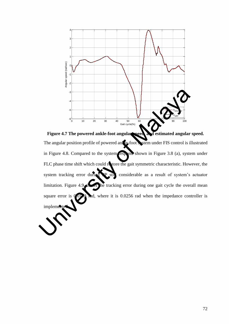
72
Figure 4.7 The powered ankle-foot angular speed, and estimated angular speed.
The angular position profile of powered ankle-foot system under FIS control is illustrated
in Figure 4.8. Compared to the system respond shown in Figure 3.8 (a), system under
FLC phase time shift which could restore the gait symmetric characteristic. However, the
system tracking error during PP still considerable as a result of system’s actuator
limitation. Figure 4.9 shows the tracking error during one gait cycle the overall mean
square error is 0.0104 rad, where it is 0.0256 rad when the impedance controller is
implemented.
0 10 20 30 40 50 60 70 80 90 100-6
-5
-4
-3
-2
-1
0
1
2
3
4
Gait cycle(%)
Angula
r speed (
rad/s
ec)
encoder
UKF
Univers
ity of
Mala
ya

73
Figure 4.8 Powered ankle-foot’s angular position for one gait cycle.
Figure 4.9 the tracking error of fuzzy logic impedance controller.
4.5 Conclusion:
In this chapter, the development of a novel fuzzy logic impedance controller was
demonstrated. Moreover, a simulation study shows the improvement which can be
0 10 20 30 40 50 60 70 80 90 100-0.5
-0.4
-0.3
-0.2
-0.1
0
0.1
0.2
0.3
Gait cycle(%)
Angula
r positio
n (
rad)
comand
encoder
UKF
0 10 20 30 40 50 60 70 80 90 100-0.16
-0.14
-0.12
-0.1
-0.08
-0.06
-0.04
-0.02
0
0.02
0.04
Gait cycle(%)
Tra
ckin
g e
rror
(ra
d)
FLCV1
tracking error
Univers
ity of
Mala
ya

74
achieved by using the fuzzy logic impedance controller. An analogy was drawn between
conventional FSM-impedance controller and the suggested control strategy.
The fuzzy logic impedance controller was based on Sugeno fuzzy model, which would
make implementing the control system in real-time achievable. Comparing the suggested
strategy with current control systems (Mai & Commuri, 2016) and (Martin & Gregg,
2017), the system will not be affected by coupling components, will not depend on the
system’s dynamic model, and less computation cost with minimum feedback signals
required.
A significant work should be done to expand control system’s knowledgebase, which
could be done by critical analysis of gait cycle categories in different speeds and terrains.
Moreover, using other biological signal such as tibia angular speed or position can
increase system ability to distinguish between working environments and speeds. Then
convert biological ankle-foot performance into fuzzy inference knowledgebase, which
could lead to the evolution of universal control strategy for powered ankle-foot prosthesis.
Univers
ity of
Mala
ya

75
CHAPTER 5 CONCLUSION AND FUTURE WORKS
5.1 Conclusion:
As highlighted in chapter 1.3, there are three objectives in this dissertation. This study is
amid at enhancing robotic ankle-foot performance by introducing a new fuzzy-logic-
based control system, and the use of PMSM as system main actuator. The fuzzy-logic
impedance controller is essential to overcome gait cycle uncertainty, where the PMSM
can enhance system performance by reducing torque ripples compared to other motors,
the ability to utilize optimal control method, and advanced sensorless driving methods.
Two estimation methods namely EKF and UKF were constructed to predict the actuator
angular speed and position, where the field oriented control is used as actuator-level
control system. Moreover, The two-level control system is used to control the robotic
ankle-foot dynamic model. It was found that, UKF algorithm is capable to provide a
feedback signals to control system with maximum error 0.4 degree. Consequentially,
mechanical design robustness will increase, maintenance requirement, actuator size will
be reduced, and finally system noise immunity will be enhanced (the high frequency
pulses of position encoders eliminated by UKF algorithm).
The novel fuzzy-logic impedance controller design is illustrated in chapter 4. It was found
that, the fuzzy-logic controller could be used as a continuous control system which
enhanced system performance compared to FSM-impedance controller. The system
knowledge base can be extended to perform properly in most operations conditions.
However, the main drawback of the new control system is power consumption which
should be solved in next version of the control system.
5.2 Future works:
The simulation study shows the advantages of utilizing FLC. Moreover, using the
sensorless driven actuator will reduce the cost and improve system’s mechanical
Univers
ityof
Malaya

76
robustness. However, the control system needs improvements in different aspects, and
the mechanical prototype should be developed. For future works, it is recommended that,
5.2.1 To modify and enhance the control system:
A further study on transforming biological ankle-foot behavior into fuzzy
linguistic rules should be conducted. The main target is reaching a universal fuzzy
logic controller, which is able to mimic ankle-foot performance. In order to attain
good dynamic performance of the robotic ankle-foot’s control system, a Genetic
Fuzzy Rule Based System (GFRBS) is proposed. By utilizing GFRBS as a control
system, it will offer a new feature for powered ankle-foot prosthesis. The system
behavior will increase as the system been used. Moreover, the control system
knowledgebase will be modified by the genetic algorithm according the
environment where the user is commonly active.
5.2.2 To develop the prototype:
In general, the prototype development could be divided into actuator design
(construction and control), and installing the actuator in robotic ankle-foot case.
The mechanical system must fulfill the biological ankle-foot categories (size,
weight, range of motion, etc.). Therefore, the mechanism should be as simple as
possible and avoid utilizing any heavy mechanical components (for example
gearbox). Finally, the work would implement the fuzzy control system and to test
the overall system. In order to ensure the safety of the subjects, a first stage testing
should be conducted on bench test then the clinical study could be initiated.
Univers
ity of
Mala
ya

77
References Ajiboye, A. B., & Weir, R. F. (2005). A heuristic fuzzy logic approach to EMG pattern
recognition for multifunctional prosthesis control. IEEE transactions on neural
systems and rehabilitation engineering, 13(3), 280-291.
Au, S., Berniker, M., & Herr, H. (2008). Powered ankle-foot prosthesis to assist level-
ground and stair-descent gaits. Neural Networks, 21(4), 654-666.
Au, S. K., Dilworth, P., & Herr, H. (2006). An ankle-foot emulation system for the study
of human walking biomechanics. Paper presented at the Robotics and
Automation, 2006. ICRA 2006. Proceedings 2006 IEEE International
Conference on.
Au, S. K., Herr, H., Weber, J., & Martinez-Villalpando, E. C. (2007). Powered ankle-
foot prosthesis for the improvement of amputee ambulation. Paper presented at
the 2007 29th Annual International Conference of the IEEE Engineering in
Medicine and Biology Society.
Au, S. K., & Herr, H. M. (2008). Powered ankle-foot prosthesis. Robotics & automation
magazine, IEEE, 15(3), 52-59.
Au, S. K., Weber, J., & Herr, H. (2007). Biomechanical design of a powered ankle-foot
prosthesis. Paper presented at the Rehabilitation Robotics, 2007. ICORR 2007.
IEEE 10th International Conference on.
Au, S. K., Weber, J., & Herr, H. (2009). Powered Ankle--Foot Prosthesis Improves
Walking Metabolic Economy. IEEE Transactions on Robotics, 25(1), 51-66.
Aubin, P. M., Whittaker, E., & Ledoux, W. R. (2012). A robotic cadaveric gait
simulator with fuzzy logic vertical ground reaction force control. IEEE
Transactions on Robotics, 28(1), 246-255.
Bellman, R. D., Holgate, M. A., & Sugar, T. G. (2008). SPARKy 3: Design of an active
robotic ankle prosthesis with two actuated degrees of freedom using
regenerative kinetics. Paper presented at the Biomedical Robotics and
Biomechatronics, 2008. BioRob 2008. 2nd IEEE RAS & EMBS International
Conference on.
Benjak, O., & Gerling, D. (2010). Review of position estimation methods for IPMSM
drives without a position sensor part I: Nonadaptive methods. Paper presented at
the Electrical Machines (ICEM), 2010 XIX International Conference on.
Bergelin, B. J., & Voglewede, P. A. (2012). Design of an active ankle-foot prosthesis
utilizing a four-bar mechanism. Journal of Mechanical Design, 134(6), 061004.
Brockett, C. L., & Chapman, G. J. (2016). Biomechanics of the ankle. Orthopaedics
and trauma, 30(3), 232-238.
Chen, B., Feng, Y., & Wang, Q. (2016). Combining vibrotactile feedback with
volitional myoelectric control for robotic transtibial prostheses. Frontiers in
Neurorobotics, 10.
Univers
ity of
Mala
ya

78
Chen, B., & Wang, Q. (2015). Combining human volitional control with intrinsic
controller on robotic prosthesis: A case study on adaptive slope walking. Paper
presented at the Engineering in Medicine and Biology Society (EMBC), 2015
37th Annual International Conference of the IEEE.
Chen, B., Wang, Q., & Wang, L. (2015). Adaptive slope walking with a robotic
transtibial prosthesis based on volitional EMG control. Mechatronics,
IEEE/ASME Transactions on, 20(5), 2146-2157.
Cherelle, P., Grosu, V., Cestari, M., Vanderborght, B., & Lefeber, D. (2016). The AMP-
Foot 3, new generation propulsive prosthetic feet with explosive motion
characteristics: design and validation. BioMedical Engineering OnLine, 15(3),
21.
Cherelle, P., Grosu, V., Matthys, A., Vanderborght, B., & Lefeber, D. (2014). Design
and validation of the ankle mimicking prosthetic (AMP-) foot 2.0. IEEE
transactions on neural systems and rehabilitation engineering, 22(1), 138-148.
Cherelle, P., Junius, K., Grosu, V., Cuypers, H., Vanderborght, B., & Lefeber, D.
(2014). The amp-foot 2.1: actuator design, control and experiments with an
amputee. Robotica, 32(08), 1347-1361.
Cherelle, P., Mathijssen, G., Wang, Q., Vanderborght, B., & Lefeber, D. (2014).
Advances in propulsive bionic feet and their actuation principles. Advances in
Mechanical Engineering.
Cherelle, P., Matthys, A., Grosu, V., Vanderborght, B., & Lefeber, D. (2012). The
AMP-Foot 2.0: Mimicking intact ankle behavior with a powered transtibial
prosthesis. Paper presented at the Biomedical Robotics and Biomechatronics
(BioRob), 2012 4th IEEE RAS & EMBS International Conference on.
Chiasson, J. (2005). Modeling and high performance control of electric machines (Vol.
26): John Wiley & Sons.
D’Andrea, S., Wilhelm, N., Silverman, A. K., & Grabowski, A. M. (2014). Does use of
a powered ankle-foot prosthesis restore whole-body angular momentum during
walking at different speeds? Clinical Orthopaedics and Related Research®,
472(10), 3044-3054.
Eilenberg, M. F., Geyer, H., & Herr, H. (2010). Control of a powered ankle–foot
prosthesis based on a neuromuscular model. IEEE transactions on neural
systems and rehabilitation engineering, 18(2), 164-173.
Eslamy, M., Grimmer, M., Rinderknecht, S., & Seyfarth, A. (2013). Does it pay to have
a damper in a powered ankle prosthesis? A Power-Energy Perspective. Paper
presented at the Rehabilitation Robotics (ICORR), 2013 IEEE International
Conference on.
Feng, Y., Zhu, J., & Wang, Q. (2016). Metabolic cost of level-ground walking with a
robotic transtibial prosthesis combining push-off power and nonlinear damping
behaviors: Preliminary results. Paper presented at the Engineering in Medicine
Univers
ity of
Mala
ya

79
and Biology Society (EMBC), 2016 IEEE 38th Annual International Conference
of the.
Gao, F., Liu, Y., & Liao, W.-H. (2016). A new powered ankle-foot prosthesis with
compact parallel spring mechanism. Paper presented at the Robotics and
Biomimetics (ROBIO), 2016 IEEE International Conference on.
Grimmer, M., Holgate, M., Holgate, R., Boehler, A., Ward, J., Hollander, K., . . .
Seyfarth, A. (2016). A powered prosthetic ankle joint for walking and running.
BioMedical Engineering OnLine, 15(3), 37.
Hansen, A. H., Childress, D. S., Miff, S. C., Gard, S. A., & Mesplay, K. P. (2004). The
human ankle during walking: implications for design of biomimetic ankle
prostheses. Journal of biomechanics, 37(10), 1467-1474.
Hitt, J., Merlo, J., Johnston, J., Holgate, M., Boehler, A., Hollander, K., & Sugar, T.
(2010). Bionic running for unilateral transtibial military amputees. Retrieved
from
Hitt, J., & Sugar, T. (2010). Load carriage effects on a robotic transtibial prosthesis.
Paper presented at the Control Automation and Systems (ICCAS), 2010
International Conference on.
Hitt, J. K., Bellman, R., Holgate, M., Sugar, T. G., & Hollander, K. W. (2007). The
sparky (spring ankle with regenerative kinetics) project: Design and analysis of
a robotic transtibial prosthesis with regenerative kinetics. Paper presented at the
ASME 2007 International Design Engineering Technical Conferences and
Computers and Information in Engineering Conference.
Hitt, J. K., Sugar, T. G., Holgate, M., & Bellman, R. (2010). An active foot-ankle
prosthesis with biomechanical energy regeneration. Journal of Medical Devices,
4(1), 011003.
Hogan, N., & Buerger, S. P. (2005). Impedance and interaction control. Robotics and
automation handbook, 1.
Holgate, M. A., Hitt, J. K., Bellman, R. D., Sugar, T. G., & Hollander, K. W. (2008).
The SPARKy (Spring Ankle with Regenerative kinetics) project: Choosing a DC
motor based actuation method. Paper presented at the Biomedical Robotics and
Biomechatronics, 2008. BioRob 2008. 2nd IEEE RAS & EMBS International
Conference on.
Holgate, M. A., Sugar, T. G., & Böhler, A. W. (2009). A novel control algorithm for
wearable robotics using phase plane invariants. Paper presented at the Robotics
and Automation, 2009. ICRA'09. IEEE International Conference on.
Jimenez-Fabian, R., Flynn, L., Geeroms, J., Vitiello, N., Vanderborght, B., & Lefeber,
D. (2015). Sliding-Bar MACCEPA for a Powered Ankle Prosthesis. Journal of
Mechanisms and Robotics, 7(4), 041011.
Jimenez-Fabian, R., Geeroms, J., Flynn, L., Vanderborght, B., & Lefeber, D. (2017).
Reduction of the torque requirements of an active ankle prosthesis using a
parallel spring. Robotics and Autonomous Systems, 92, 187-196.
Univers
ity of
Mala
ya

80
Jimenez-Fabian, R., & Verlinden, O. (2012). Review of control algorithms for robotic
ankle systems in lower-limb orthoses, prostheses, and exoskeletons. Medical
engineering & physics, 34(4), 397-408.
Ju, M.-S., Lin, C.-C., Lin, D.-H., Hwang, I.-S., & Chen, S.-M. (2005). A rehabilitation
robot with force-position hybrid fuzzy controller: hybrid fuzzy control of
rehabilitation robot. IEEE transactions on neural systems and rehabilitation
engineering, 13(3), 349-358.
Julier, S. J., & Uhlmann, J. K. (1996). A general method for approximating nonlinear
transformations of probability distributions. Retrieved from
Kannape, O. A., & Herr, H. M. (2014). Volitional control of ankle plantar flexion in a
powered transtibial prosthesis during stair-ambulation. Paper presented at the
Engineering in Medicine and Biology Society (EMBC), 2014 36th Annual
International Conference of the IEEE.
Kannape, O. A., & Herr, H. M. (2016). Split-belt adaptation and gait symmetry in
transtibial amputees walking with a hybrid EMG controlled ankle-foot
prosthesis. Paper presented at the Engineering in Medicine and Biology Society
(EMBC), 2016 IEEE 38th Annual International Conference of the.
Kovacic, Z., & Bogdan, S. (2005). Fuzzy controller design: theory and applications
(Vol. 19): CRC press.
LaPre, A. K., & Sup, F. (2013). Redefining prosthetic ankle mechanics: Non-
anthropomorphic ankle design. Paper presented at the Rehabilitation Robotics
(ICORR), 2013 IEEE International Conference on.
LaPrè, A. K., Umberger, B. R., & Sup, F. (2014). Simulation of a powered ankle
prosthesis with dynamic joint alignment. Paper presented at the Engineering in
Medicine and Biology Society (EMBC), 2014 36th Annual International
Conference of the IEEE.
LaPre, A. K., Umberger, B. R., & Sup, F. C. (2016). A Robotic Ankle–Foot Prosthesis
With Active Alignment. Journal of Medical Devices, 10(2), 025001.
Mai, A., & Commuri, S. (2011). Gait identification for an intelligent prosthetic foot.
Paper presented at the Intelligent Control (ISIC), 2011 IEEE International
Symposium on.
Mai, A., & Commuri, S. (2016). Intelligent control of a prosthetic ankle joint using gait
recognition. Control Engineering Practice, 49, 1-13.
Martin, A. E., & Gregg, R. D. (2015). Hybrid invariance and stability of a feedback
linearizing controller for powered prostheses. Paper presented at the American
Control Conference (ACC), 2015.
Martin, A. E., & Gregg, R. D. (2017). Stable, robust hybrid zero dynamics control of
powered lower-limb prostheses. IEEE Transactions on Automatic Control.
Univers
ity of
Mala
ya

81
Meinders, M., Gitter, A., & Czerniecki, J. (1998). The role of ankle plantar flexor
muscle work during walking. Scandinavian journal of rehabilitation medicine,
30(1), 39-46.
Meinders, M., Gitter, A., & Czerniecki, J. M. (1998). The role of ankle plantar flexor
muscle work during walking. Scandinavian journal of rehabilitation medicine,
30(1), 39-46.
Momen, K., Krishnan, S., & Chau, T. (2007). Real-time classification of forearm
electromyographic signals corresponding to user-selected intentional movements
for multifunction prosthesis control. IEEE transactions on neural systems and
rehabilitation engineering, 15(4), 535-542.
Nordin, M., & Frankel, V. H. (2001). Basic biomechanics of the musculoskeletal
system: Lippincott Williams & Wilkins.
Oviedo, J. J. E., Vandewalle, J. P., & Wertz, V. (2006). Fuzzy logic, identification and
predictive control: Springer Science & Business Media.
Peasgood, M., Kubica, E., & McPhee, J. (2007). Stabilization of a dynamic walking gait
simulation. Journal of computational and nonlinear dynamics, 2(1), 65-72.
Pickle, N. T., Wilken, J. M., Aldridge, J. M., Neptune, R. R., & Silverman, A. K.
(2014). Whole-body angular momentum during stair walking using passive and
powered lower-limb prostheses. Journal of biomechanics, 47(13), 3380-3389.
Pickle, N. T., Wilken, J. M., Whitehead, J. M. A., & Silverman, A. K. (2016). Whole-
body angular momentum during sloped walking using passive and powered
lower-limb prostheses. Journal of biomechanics, 49(14), 3397-3406.
Pillay, P., & Krishnan, R. (1991). Application characteristics of permanent magnet
synchronous and brushless DC motors for servo drives. IEEE Transactions on
industry applications, 27(5), 986-996.
Po-Fu, S., Gard, S. A., Lipschutz, R. D., & Kuiken, T. A. (2007). Gait characteristics of
persons with bilateral transtibial amputations. Journal of rehabilitation research
and development, 44(4), 491.
Quesada, R. E., Caputo, J. M., & Collins, S. H. (2016). Increasing ankle push-off work
with a powered prosthesis does not necessarily reduce metabolic rate for
transtibial amputees. Journal of biomechanics, 49(14), 3452-3459.
Quintero, D., Martin, A. E., & Gregg, R. D. (2017). Toward Unified Control of a
Powered Prosthetic Leg: A Simulation Study. IEEE Transactions on Control
Systems Technology.
Rouse, E. J., Hargrove, L. J., Perreault, E. J., & Kuiken, T. A. (2012). Estimation of
human ankle impedance during walking using the perturberator robot. Paper
presented at the Biomedical Robotics and Biomechatronics (BioRob), 2012 4th
IEEE RAS & EMBS International Conference on.
Rouse, E. J., Villagaray-Carski, N. C., Emerson, R. W., & Herr, H. M. (2015). Design
and Testing of a Bionic Dancing Prosthesis. PloS one, 10(8), e0135148.
Univers
ity of
Mala
ya

82
Seymour, R. (2002). Prosthetics and orthotics: lower limb and spinal: Lippincott
Williams & Wilkins.
Shultz, A., Lawson, B., & Goldfarb, M. (2015). Variable Cadence Walking and Ground
Adaptive Standing with a Powered Ankle Prosthesis.
Shultz, A. H., Lawson, B. E., & Goldfarb, M. (2015). Walking on uneven terrain with a
powered ankle prosthesis: A preliminary assessment. Paper presented at the
Engineering in Medicine and Biology Society (EMBC), 2015 37th Annual
International Conference of the IEEE.
Shultz, A. H., Mitchell, J. E., Truex, D., Lawson, B. E., & Goldfarb, M. (2013).
Preliminary evaluation of a walking controller for a powered ankle prosthesis.
Paper presented at the Robotics and automation (ICRA), 2013 IEEE
international conference on.
Simon, A. M., Ingraham, K. A., Fey, N. P., Finucane, S. B., Lipschutz, R. D., Young,
A. J., & Hargrove, L. J. (2014). Configuring a powered knee and ankle
prosthesis for transfemoral amputees within five specific ambulation modes.
PloS one, 9(6), e99387.
Smith, J. D., & Martin, P. E. (2013). Effects of prosthetic mass distribution on
metabolic costs and walking symmetry. Journal of Applied Biomechanics, 29(3),
317-328.
Sun, J., Fritz, J. M., Del Toro, D. R., & Voglewede, P. A. (2014). Amputee Subject
Testing Protocol, Results, and Analysis of a Powered Transtibial Prosthetic
Device. Journal of Medical Devices, 8(4), 041007.
Sun, J., & Voglewede, P. A. (2011). Controller implementation of a powered transtibial
prosthetic device. Paper presented at the ASME 2011 International Design
Engineering Technical Conferences and Computers and Information in
Engineering Conference.
Sun, J., & Voglewede, P. A. (2014). Powered transtibial prosthetic device control
system design, implementation, and bench testing. Journal of Medical Devices,
8(1), 011004.
Tran, H. T., Cheng, H., Rui, H., Lin, X., Duong, M. K., & Chen, Q. (2016). Evaluation
of a fuzzy-based impedance control strategy on a powered lower exoskeleton.
International Journal of Social Robotics, 8(1), 103-123.
Vas, P. (1990). Vector control of AC machines (Vol. 22): Oxford University Press,
USA.
Vas, P. (1998). Sensorless vector and direct torque control: Oxford Univ. Press.
Vaughan, C. L., Davis, B. L., & Jeremy, C. (1999). Dynamics of human gait.
Versluys, R., Desomer, A., Lenaerts, G., Van Damme, M., Beyl, P., Van Der Perre, G., .
. . Lefeber, D. (2008). A pneumatically powered below-knee prosthesis: Design
specifications and first experiments with an amputee. Paper presented at the
Univers
ity of
Mala
ya

83
Biomedical Robotics and Biomechatronics, 2008. BioRob 2008. 2nd IEEE RAS
& EMBS International Conference on.
Wan, E., & Van Der Merwe, R. (2001). The Unscented Kalman Filter, to appear in
Kalman Filtering and Neural Networks, Chapter 7, Edited by Simon Haykin. In:
John Wiley & Sons, USA.
Wang, Q., Yuan, K., Zhu, J., & Wang, L. (2014). Finite-state control of a robotic
transtibial prosthesis with motor-driven nonlinear damping behaviors for level
ground walking. Paper presented at the Advanced motion control (AMC), 2014
IEEE 13th international workshop on.
Wang, Q., Yuan, K., Zhu, J., & Wang, L. (2015). Walk the walk: A lightweight active
transtibial prosthesis. IEEE Robotics & Automation Magazine, 22(4), 80-89.
Waters, R. L., Perry, J., Antonelli, D., & Hislop, H. (1976). Energy cost of walking of
amputees: the influence of level of amputation. J Bone Joint Surg Am, 58(1), 42-
46.
Wen, Y., Si, J., Gao, X., Huang, S., & Huang, H. (2016). A New Powered Lower Limb
Prosthesis Control Framework Based on Adaptive Dynamic Programming. IEEE
transactions on neural networks and learning systems.
Winter, D. A. (1983). Biomechanical motor patterns in normal walking. Journal of
motor behavior, 15(4), 302-330.
Winter, D. A. (2009). Biomechanics and motor control of human movement: John
Wiley & Sons.
Yeadon, W., & Yeadon, A. (2001). Handbook of Small Electric Motors: McGraw-Hill
Education.
Yu, T., Plummer, A., Iravani, P., Bhatti, J., Obe, S. Z., & Moser, D. (2016). Testing an
Electrohydrostatic Powered Ankle Prosthesis with Transtibial and Transfemoral
Amputees. IFAC-PapersOnLine, 49(21), 185-191.
Yu, T., Plummer, A., Iravani, P., Bhatti, J., Zahedi, S., & Moser, D. (2016). The Design,
Analysis and Testing of a Compact Electrohydrostatic Powered Ankle
Prosthesis. Paper presented at the BATH/ASME 2016 Symposium on Fluid
Power and Motion Control.
Yuan, K., Sun, S., Wang, Z., Wang, Q., & Wang, L. (2013). A fuzzy logic based terrain
identification approach to prosthesis control using multi-sensor fusion. Paper
presented at the Robotics and Automation (ICRA), 2013 IEEE International
Conference on.
Yuan, K., Wang, Q., & Wang, L. (2015). Fuzzy-logic-based terrain identification with
multisensor fusion for transtibial amputees. Mechatronics, IEEE/ASME
Transactions on, 20(2), 618-630.
Univers
ity of
Mala
ya

84
Yuan, K., Wang, Q., Zhu, J., & Wang, L. (2014). Motion control of a robotic transtibial
prosthesis during transitions between level ground and stairs. Paper presented at
the Control Conference (ECC), 2014 European.
Zadeh, L. A. (1965). Fuzzy sets. Information and control, 8(3), 338-353.
Zheng, H., & Shen, X. (2015). Design and Control of a Pneumatically Actuated
Transtibial Prosthesis. Journal of bionic engineering, 12(2), 217-226.
Zhu, J., Wang, Q., & Wang, L. (2010). PANTOE 1: Biomechanical design of powered
ankle-foot prosthesis with compliant joints and segmented foot. Paper presented
at the Advanced Intelligent Mechatronics (AIM), 2010 IEEE/ASME
International Conference on.
Zhu, J., Wang, Q., & Wang, L. (2014). On the design of a powered transtibial prosthesis
with stiffness adaptable ankle and toe joints. IEEE Transactions on Industrial
Electronics, 61(9), 4797-4807.
Ziegler-Graham, K., MacKenzie, E. J., Ephraim, P. L., Travison, T. G., & Brookmeyer,
R. (2008). Estimating the prevalence of limb loss in the United States: 2005 to
2050. Archives of physical medicine and rehabilitation, 89(3), 422-429.
Univers
ity of
Mala
ya

85
LIST OF PUBLICATIONS
JOURNAL PAPERS
1. Mouaz Al-Kouzbary, Noor Azuan Abu Osman, and Ahmad Khairi Abdul
Wahab, Sensorless control system of assistive robotic ankle foot. Submitted to
International Journal of Advanced Robotic Systems on 11 Jan 2018. (Status:
Accepted on 16 Apr 2018; Page Proof on 3 May 2018, Published online on 17
May 2018) (ISI-Indexed).
2. Mouaz Al Kouzbary, Noor Azuan Abu Osman, and Ahmad Khairi Abdul
Wahab, Evolution and Current Development of Powered Ankle–Foot Prostheses:
A Systematic Review (Under review-2nd review -31 May 2018- in Proceedings of
the Institution of Mechanical Engineers, Part H: Journal of Engineering in
Medicine).
3. Mouaz Al Kouzbary, Noor Azuan Abu Osman, Ahmad Khairi Abdul Wahab,
Sensorless Fuzzy Logic Control System Structure for Assistive Robotic Ankle-
Foot (Under review -30 September 2018- in the International Journal of Fuzzy
Logic Systems).
Univers
ity of
Mala
ya