Embed Size (px)
Citation preview

04581245Edition 2
May 2014
Save These Instructions
Air Grinder,Die Grinder and SanderSeries G2 (Angle)
Maintenance Information

2 04581245_ed2
Product Safety Information
WARNING
Failure to observe the following warnings, and to avoid these potentially hazardous situations, could result in death or serious injury.Read and understand this and all other supplied manuals before installing, operating, repairing, maintaining, changing accessories on, or working near this product.Always wear eye protection when operating or performing maintenance on this tool. The grade of protection required should be assessed for each use and may include impact-resistant glasses with side shields, goggles, or a full face shield over those glasses.Always turn off the air supply, bleed the air pressure and disconnect the air supply hose when not in use, before installing, removing or adjusting any accessory on this tool, or before performing any maintenance on this tool or any accessory.Do not use this tool if the actual free speed exceeds the rated rpm. Check the free speed of this tool before mounting any accessories, after all tool repairs, before each job and after every 8 hours of use. Check speed with a calibrated tachometer, without the abrasive product installed.
Note: When reading the instructions, refer to exploded diagrams in parts Information Manuals when applicable (see under Related Documentation for form numbers).
••
•
•
•
Whenever one of these Grinder, Die Grinder or Sander is disassembled for overhaul or replacement of parts, lubricate the tool as follows:
Always wipe the Vanes (28) with a light film of oil before inserting them into the vane slots.Inject 0.5 to 1.0 cm3 of Ingersoll Rand No. 10 Oil into the air Inlet Assembly (1) after assembly.
1.
2.
Whenever a new Wick (53 or 72) is installed, soak the Wick in approximately 1-1/2 cm³ of Ingersoll Rand No. 63 Oil. Do not substitute any other oil.Whenever the motor is disassembled, remove the old grease and refill the cavity behind the Rear Rotor Bearing (25) with 3/4 cm³ of Ingersoll Rand No. 68 Grease.
3.
4.
General InstructionsDo not disassemble the tool any further than necessary to replace or repair damaged parts.When grasping a tool or part in a vise, always use softsided vise jaws to protect the surface of the part or tool and help prevent distortion. This is particularly true of threaded members and housings.When grasping a tool in a vise, first place the tool housing in the provided Clamp Tool (38), then grasp outer surface of Clamp Tool in the vise to protect the housing from damage.Do not remove any part which is a press fit in or on a subassembly unless the removal of that part is necessary for repairs or replacement.Do not disassemble the tool unless you have a complete set of new gaskets and O-Rings for replacement.Do not press any needle bearing from a part unless you have a new needle bearing on hand for installation. Needle bearings are always damaged during the removal process.
Disassembly of all Angle HeadsFor all Collet models, grasp the tool, mounted in the Clamp Tool (96), in soft-sided vise jaws with the Collet (77) upward. Using the Collet Body Wrench (89) on the flats of the Collet Arbor (76) and the Collet Nut Wrench (90) on the Collet Nut (78), unscrew the Collet Nut and remove the Collet.For All Wheel models grasp the tool, mounted in the Clamp Tool (96), in soft-sided vise jaws with the Flange Nut (85) upward.For models ending in P945, P95 or P96 use a 4 mm hex wrench to unscrew the Wheel Retaining Screw (87).Use the Arbor Wrench (91) to hold the Arbor (76) and using the Flange Nut Wrench (93 or 94), unscrew and remove the Flange Nut. Remove the Wheel Retaining Screw Washer (88), the wheel, Wheel Flange (84) and Flange spacer (86) from the Arbor.For G2E models, using a 9/64” hex wrench, loosen the Wheel Guard Adapter Screw (80) and remove the Guard Adapter Assembly (79) from the Angle Housing Assembly (48).
For G2A and G2L models, using a 5/32” hex wrench, loosen Guard Adapter Screw (80) and remove the Guard Adapter Assembly (79) from the Angle Housing Assembly (67).
6. Using a 1/8” hex wrench, unscrew and remove the three Guard Mounting Screws (83), Guard Lock Washers (82) and Wheel Guard (81).
1.
2.
3.
4.
5.
6.
1.
2.
3.
4.
5.
7. For all Sander models, grasp the tool, mounted in the Clamp Tool (96), in soft-sided vise jaws with the Arbor (76) facing upward.
For All models - Continue Here8. For G2A and G2L models, using a spanner wrench, unscrew and
remove the Arbor Bearing Cap (75). This is a left-hand thread. Rotate the Cap Wrench clockwise to remove the Cap.
For G2E models, using the Arbor Bearing Cap Wrench (92), unscrew and remove the Arbor Bearing Cap (56). This is a left-hand thread. Rotate the Cap Wrench clockwise to remove the Cap.
9. For G2A and G2L models, using the Clamp Nut Wrench (95), loosen the Clamp Nut (69) and pull the Angle Housing Assembly (67) away from the Motor Housing (12) or Extension Housing (61). This is a left-hand thread. Rotate the Nut Wrench clockwise to loosen the Nut.
For G2E models, using the Clamp Nut Wrench (95), loosen the Clamp Nut (50) and pull the Angle Housing Assembly (48) away from the Extension Housing (43). This is a left-hand thread. Rotate the Nut Wrench clockwise to loosen the Nut.
10. Grasp the Arbor and pull the assembled Arbor out of the Angle Head. If the Wick (53 or 72) needs replacement, pull it out of the Angle Housing.
11. If the Upper Arbor Bearing (52 or 71) needs replacement, support the Angle Head on the table of an arbor press, bearing end down, and press the Bearing out of the Angle Head.
12. Grasp the Arbor in soft sided vise jaws with the output end downward. Using an adjustable wrench, unscrew and remove the Bevel Gear Nut (54 or 73) and lift the Bevel Gear (66) off the Arbor.
13. If the Lower Arbor Bearing (55 or 74) must be replaced, use a piece of tubing to support the Bearing on the table of an arbor press and press the Arbor from the Bearing.
WARNINGWhen removing the Clamp Nut in the following procedure, take all precautions necessary to prevent the Spacer from being forcefully ejected in a manner or direction that is hazardous.14. If the Clamp Nut (50 or 69) must be removed from the Angle
Housing, insert the blades of two screwdrivers, approximately 180 degrees apart, under the Clamp Spacer (49 or 68) and pry the Spacer off the Housing.
Lubrication
Disassembly

04581245_ed2 3
Disassembly of Extension Assembly on G2E and G2L Models
Grasp the tool mounted in the Clamp Tool (96), in softsided vise jaws with the Spindle (64 or 45) upward. Using the Clamp nut Wrench (95) on the flats of the Extension Housing (43 or 61), unscrew and remove the assembled Housing. This is a left-hand thread. Rotate the Housing clockwise to remove it. Remove the Arbor Coupling (39 or 57) and Clamp Sleeve (40 or 58).For G2E models, using snap ring pliers, remove the Coupling Retaining Ring (42) from the Spindle Bearing Nut (41) in the large end of the Extension Housing.After removing the Retaining Ring, push on the Nut end of the Spindle until the assembled Spindle exits the angle head end of the Extension Housing. The Rear Spindle Bearing (44) will remain in the Housing and the Nut will pass through the Bearing.If the Front Spindle Bearing (46) must be replaced, use a 1/2” wrench on the flats of the Bevel Pinion (47) and the Spindle Bearing Nut to unscrew and remove either the Pinion or Nut. Using an adjustable wrench on the flats of the Spindle, remove whichever component remained threaded onto the Spindle. Press the Bearing from the Spindle.If the Rear Spindle Bearing must be replaced, press the Bearing out of the large end of the Extension Housing.For G2L models, grasp the Bevel Pinion (66) and pull the assembled Spindle from the Extension Housing. Remove the two Rear Spindle Bearing Washers (63) from the Housing.Using snap ring pliers, remove the Coupling Retaining Ring (60) from the Spindle Bearing Nut (59) on the assembled Spindle.Grasp a 5/32” diameter steel pin vertically in a set of vise jaws and slide the crosshole of the assembled Spindle down onto the pin.Using a 1/2” wrench, unscrew and remove the Spindle Bearing Nut.Using a 9/16” wrench, unscrew and remove the Bevel Pinion.Using a bearing puller, pull the Rear Spindle Bearing (62) off the Spindle.Using a bearing puller or arbor press, pull or press the Front Spindle Bearing (65) off the Spindle.
Disassembly of the MotorRemove the Flange clamp (35) and front Housing Cap (34) from the front of the Motor Housing Assembly (12). Remove the Front Muffler (33) if it remains in the Housing.Grasp the Bevel Pinion (66) or Spindle Bearing Nut (41 or 59) and pull the assembled motor out of the Motor Housing. Remove the two Rear Rotor Bearing Spacers (26) from the bottom of the Cylinder (17).Remove the Vanes (28) from the Rotor (27).Grasp the Rotor in smooth sided vise jaws with the Bevel Pinion
1.
2.
3.
4.
5.
6.
7.
8.
9.
10.11.
12.
1.
2.
3.4.
or Spindle Bearing Nut upward. Using a 1/2” wrench for the Nut or a 9/16” wrench for the Pinion, unscrew and remove the Pinion or Nut.If the Front Rotor Bearing (32) must be replaced, support the Front End Plate (29) between two blocks on the table of an arbor press. Place the blocks as close to the body of the Rotor as possible and press the Rotor from the Bearing and End Plate. Remove the Front End Plate Spacer (30) and Seal Assembly (31) from the hub of the Rotor.If the Rear Rotor Bearing (25) must be replaced, use snap ring pliers to remove the Rear Rotor Bearing Retainer (24).Using a bearing puller, pull the Rear Rotor Bearing off the hub of the Rotor.
Disassembly of the Inlet and ThrottleUsing a 15/16” wrench or six point socket, unscrew and remove the Inlet Assembly (1).Remove the Inlet Seal (2), Inlet Screen and Ball Valve Spring Seat from the Inlet.Remove the Ball (4) and Ball Valve Spring (3) from the Cylinder Assembly (17).Press the Throttle Lever Pin (7) from the Rear Exhaust Diffuser (5) and remove the Lever Assembly (9).Remove the Rear Exhaust Diffuser from the Housing. Remove Rear Exhaust Diffuser Gasket (8), Rear Exhaust Diffuser Muffler (10) and Lever Support (6) from the Diffuser.If the Ball Valve Seat (16) must be replaced, insert a hooked tool through the central opening of the Seat and, catching the underside of the Seat, pull it from the Housing.Remove Rear Housing Muffler (11) from the Housing.Push throttle Pin Assembly (18) out of Housing and remove from opening in Cylinder.Remove Throttle Pin O-Ring (19) from throttle Pin.
Disassembly of Motor Housing and CylinderPlace Cylinder, Inlet end down, on flat hard surface. Grasp Housing and pull down to separate it from the Cylinder. Pull Cylinder out of Housing.Remove Flow Guide Assembly (20) and Intake Cover Assembly (22) from Exhaust Seal (14).Remove Flow Guide O-Rings (21) from Flow Guide.Remove Intake Cover O-Ring (23) from Intake Cover.Remove Rear Cylinder O-Ring (13) and then the Exhaust Seal from the Cylinder.Remove Front Cylinder O-Ring (15) from the Cylinder.If the Throttle Bushing needs to be replaced, insert a small hooked tool into the hole in the bushing and catch the underside. Pull Bushing from Cylinder.
5.
6.
7.
1.
2.
3.
4.
5.
6.
7.8.
9.
1.
2.
3.4.5.
6.7.
Assembly
General InstructionsAlways press on the inner ring of a ball-type bearing when installing the bearing on a shaft.Always press on the outer ring of a ball-type bearing when pressing the bearing into a bearing recess.Whenever grasping a tool or part in a vise, always use soft-sided vise jaws. Take extra care not to damage threads or distort housings.When grasping a tool in a vise, first place the tool housing in the provided Clamp Tool (38), then grasp outer surface of Clamp Tool in the vise to protect the housing from damage.Except for bearings, always clean every part and wipe every part with a thin film of oil before installation.Check every bearing for roughness. If an open bearing must be cleaned, wash it thoroughly in clean solvent and dry with a clean cloth. Sealed or shielded bearings should not be cleaned. Work grease into every open bearing before installation.Apply a film of O-Ring lubricant to every O-Ring before installation.
1.
2.
3.
4.
5.
6.
7.
Unless otherwise noted, always press on the stamped end of a needle bearing when installing a needle bearing into a recess.
Assembly of Motor Housing and CylinderIf the Throttle Bushing was removed, Properly secure the Cylinder (17) and press the Throttle Bushing into the hole on the side of the Cylinder closest to threaded opening.Apply O-Ring lubricant to the Front Cylinder O-Ring (15) and install onto the small end of Cylinder. Slide O-Ring past all inlet and exhaust slots, into Front O-Ring groove.Install Exhaust Seal (14) onto small end of Cylinder and move it all the way down over O-Ring. Line up and seat protrusion on Exhaust Seal with slot in Cylinder for proper orientation.Install the Rear Cylinder O-Ring (13) onto small end of Cylinder. Slide O-Ring into rear O-Ring groove in Cylinder.Install two Flow Guide O-Rings (21) in grooves on Flow Guide (20).Install Intake Cover O-Ring (23) in groove on Intake Cover (22).Assemble Flow Guide onto Cylinder. Be sure O-Rings are installed on the Flow Guide before assembly. For rear exhaust insert the rubber plugs on the Flow Guide into the holes in the Exhaust Seal.
8.
1.
2.
3.
4.
5.6.7.
4 04581245_ed2
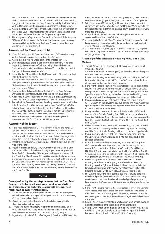
For front exhaust, insert the Flow Guide tabs into the Exhaust Seal holes. There is a protrusion on the Exhaust Seal that inserts into the groove in the top of the Flow Guide. Especially, for Flow Guide without tabs, be sure this protrusion is inserted in this groove.Assemble Intake Cover onto Cylinder. There is a tab on the front of the Intake Cover that inserts into the Exhaust Seal and a tab that inserts into a hole in the Cylinder for proper alignment.Place large end of Cylinder on flat hard surface and slide Housing (12) over Cylinder assembly. Be sure that hole in top of Housing lines up with hole in Throttle Bushing. Press down on Housing until these holes are aligned.
Assembly of the Throttle and InletIf the Ball Valve Seat (16) was removed, use a 5/8” wooden dowel with a flat end to push the Seat into the Cylinder.Assemble Throttle Pin O-Ring (19) onto Throttle Pin (18).Using needle nose pliers, grasp Throttle Pin above O-Ring and insert into threaded end of Cylinder. Align Pin with holes in Cylinder and Housing and insert. Release Throttle Pin and push it the rest of the way into the hole.Insert the Ball (4) and then the Ball Valve Spring (3) small end first into the Cylinder opening.Assemble Lever Support (6) into Rear Exhaust Diffuser (5), the U shaped side of support inserted first into front of the Diffuser. Slide tabs into the slots on the Diffuser and line up the holes with the holes in the Diffuser.Assemble Rear Exhaust Diffuser Gasket (8) onto Rear Exhaust Diffuser and assemble Diffuser onto the Housing Assembly.Align hole in Lever Assembly (9) with hole in Exhaust Diffuser and press the Throttle Lever Pin (7) through Exhaust Diffuser holes.Push the Inlet Screen closed end leading, into the small end of the Inlet Assembly (1). After lubricating the Inlet Seal (2) with O-Ring lubricant and being careful not to nick the Seal on the threads of the Inlet, install the Seal on the Inlet. Press the Ball Valve Spring Seat small end leading into the small end of the Inlet.Thread the Inlet Assembly into the Cylinder and tighten it between 20 to 25 ft–lb (27.1 to 33.9 Nm) torque.
Assembly of the MotorIf the Rear Rotor Bearing (25) was removed, stand the Rotor (27) upright on the table of an arbor press with the threaded end downward. Place the threaded rotor hub into a hole drilled into a flat, smooth block so that the Rotor rests flat on the large rotor body. Press the Rear Rotor Bearing onto the hub of the Rotor.Install the Rear Rotor Bearing Retainer (24) in the groove on the hub of the Rotor.Install the Front End Plate (29), counterbored end trailing, onto the threaded hub of the Rotor. Using finger pressure, press the Front Seal Cup Assembly (31), felt end trailing, onto the end of the Front End Plate Spacer (30) that is opposite the large internal bevel. Continue pressing until the felt end is flush with the end of the Spacer. Saturate the felt with Ingersoll Rand No. 50 Oil. Place the assembled Spacer, Seal Assembly trailing, onto the threaded hub of the Rotor. Make sure the Seal Assembly enters the recess in the Front End Plate.
NOTICE
Before performing the next step, be aware that the Front Rotor Bearing is a flush ground bearing and must be installed in a specific manner. The end of the Bearing with a stain or hash marks must be away from the Spacer.4. Stand the small hub of the Rotor on the table of an arbor press
with the threaded end upward and press the Front Rotor Bearing (32) onto the hub of the Rotor.
5. Grasp the assembled Rotor in soft-sided vise jaws with the threaded rotor hub upward.
6. Thread the Bevel Pinion (66) or Spindle Bearing Nut (59 or 41) onto the Rotor and using a torque wrench, tighten the Pinion or Nut between 14 and 19 ft-lb (19.0 and 25.8 Nm) torque.
7. Inject approximately 0.7 cm3 of Ingersoll Rand No. 68 Grease into
8.
9.
1.
2.3.
4.
5.
6.
7.
8.
9.
1.
2.
3.
the small recess at the bottom of the Cylinder (17). Drop the two Rear Rotor Bearing Spacers (26) into the bottom of the Cylinder.
8. Wipe each Vane (28) with a light film of oil and insert Vane into each vane slot in the Rotor. Be sure that logo on Vane faces to the left inside the vane slot when looking down length of Rotor, with threaded end away.
9. Grasp the Bevel Pinion or Spindle Bearing Nut and insert the assembled Rotor into the Cylinder.
10. Assemble the Front Muffler (33) into the Front Housing Cap (34). Ensure muffler is installed in the Cap and does not get pushed down into the Motor Housing.
11. Assemble Front Housing Cap onto Motor Housing (12), aligning notches on Cap with notches in the Cylinder. Place Flange Clamp (35) in groove in Cap.
Assembly of the Extension Housing on G2E and G2L Models.
For G2E Models, if the Rear Spindle Bearing (44) was replaced, proceed as follows:
a. Stand the Extension Housing (43) on the table of an arbor press with the small end downward.
b. Press the Bearing into the Housing until the trailing end of the Bearing is 1.408” to 1.418” (35.7 mm to 36.0 mm) below the face of the large end of the Extension Housing.
2. If the Front Spindle Bearing (46) was replaced, stand the Spindle (45) on the table of an arbor press, small threaded end upward. Being careful not to damage the threads on the large end of the Spindle, press the Bearing, stained or marked end trailing, onto the Spindle until it seats against the shoulder of the shaft.
3. Using an adjustable wrench on the flats of the Spindle and a 9/16” wrench on the Bevel Pinion (47), thread the Pinion onto the Spindle against the Bearing and tighten it between 14 and 19 ft–lb (19.0 and 25.8 Nm) torque.
4. Using an adjustable wrench on the Spindle and a 1/2” wrench on one of the Spindle Bearing Nuts (41), thread Nut without the Coupling Retaining Ring (42), counterbored end leading, onto the Spindle. Tighten the Nut between 14 and 19 ft–lb (19.0 and 25.8 Nm) torque.
5. Insert the assembled Spindle, Nut end leading, into the small end of the Extension Housing. Push the assembly into the Housing until the Front Spindle Bearing bottoms on the housing shoulder.
6. Using snap ring pliers, install the Coupling Retaining Ring on the Spindle Bearing Nut protruding into the large end of the Extension Housing.
7. Grasp the assembled Motor Housing, mounted in Clamp Tool (96), in soft-sided vise jaws with the Spindle Bearing Nut (41) upward. Coat the inside of the Arbor Coupling 04581245_ed1 EN-4 EN (39) with approximately 1 cm3 of Ingersoll Rand No. 68 Grease and install the Coupling over the Bearing Nut. Position the Clamp Sleeve (40) over the Coupling in the ;Motor Housing.
8. Insert the Spindle Bearing Nut in the assembled Extension Housing into the Arbor Coupling and thread the Extension Housing onto the Cylinder. This is a lefthand thread; rotate the Extension Housing counterclockwise to tighten it. Tighten the Housing between 20 to 25 ft-lb (27.1 to 33.9 Nm) torque.
9. For G2L Models, if the Rear Spindle Bearing (62) was replaced, stand the Spindle (64) on the table of an arbor press and being careful not to damage the threads on the Spindle, press the Bearing onto the Spindle until it seats against the shoulder of the shaft.
10. If the Front Spindle Bearing (65) was replaced, invert the Spindle on the table of an arbor press and being careful not to damage the threads on the Spindle, press the Bearing, stained or marked end trailing, onto the Spindle until it seats against the shoulder of the shaft.
11. Grasp a 5/32” diameter steel pin vertically in a set of vise jaws and slide the crosshole of the Spindle down onto the pin.
12. Using a 9/16” wrench on the flats of the Bevel Pinion (66), thread the Pinion onto the Spindle against the Bearing and tighten it between 14 and 19 ft–lb (19.0 and 25.8 Nm) torque.
1.
04581245_ed2 5
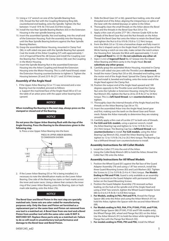
13. Using a 1/2” wrench on one of the Spindle Bearing Nuts (59), thread the Nut with the Coupling Retaining Ring (60), counterbored end leading, onto the Spindle. Tighten the Nut between 14 and 19 ft–lb (19.0 and 25.8 Nm) torque.
14. Install the two Rear Spindle Bearing Washers (63) in the Extension Housing in the rear spindle bearing cavity.
15. Insert the assembled Spindle, Nut end leading, into the small end of the Extension Housing. Push the assembly into the Housing until the Rear Spindle Bearing bottoms against the Rear Spindle Bearing Washers.
16. Grasp the assembled Motor Housing, mounted in Clamp Tool (96), in soft-sided vise jaws with the Spindle Bearing Nut upward. Coat the inside of the Arbor Coupling (57) with approximately 1 cm3 of Ingersoll Rand No. 68 Grease and install the Coupling over the Bearing Nut. Position the Clamp Sleeve (58) over the Coupling in the Motor Housing.
17. Insert the Spindle Bearing Nut in the assembled Extension Housing into the Arbor Coupling and thread the Extension Housing onto the Motor Housing. This is a left-hand thread; rotate the Extension Housing counterclockwise to tighten it. Tighten the Housing between 20 and 25 ft–lb (27.1 and 33.9 Nm) torque.
Assembly of the Angle HeadIf the Upper Arbor Bearing (52 or 71) was removed and a new Bearing must be installed, proceed as follows:
a. Support the machined face of the Angle Head (48 or 67) on the table of an arbor press with the upper arbor bearing bore upward.
NOTICE
When installing the Bearing in the next step, always press on the stamped or closed end of the Bearing.
NOTICE
Do not press the Upper Arbor Bearing flush with the top of the Angle Housing. Press the Bearing to the dimensions given in the following step. b. Press a new Upper Arbor Bearing into the bore.
PRESS IN UPPER ARBOR BEARING TO DIMENSION SHOWN
1.002.997
2. If the Lower Arbor Bearing (55 or 74) is being installed, it is necessary to note the identification marks on the Lower Arbor Bearing. One side of the Bearing has stains or hash marks across the inner and outer races. Using a sleeve that contacts the inner ring of the Lower Arbor Bearing, press the Bearing, stain or hash mark side leading, onto the Arbor (76).
NOTICE
The Bevel Gear and Bevel Pinion in the next step are specially matched sets. Some sets are color coded for manufacturing purposes only. Only the Gear and Pinion set furnished as a replacement part or the same Gear and Pinion set removed from one tool is a matched set. A Bevel Gear from one tool and a Bevel Pinion from another tool with the same color code IS NOT A MATCHED SET. Replace these parts only as a matched set. Failure to do so will result in unsatisfactory tool performance and damage to the Bevel Gear and Bevel Pinion.
1.
3. Slide the Bevel Gear (47 or 66), geared face trailing, onto the small threaded end of the Arbor, aligning the integral keys or spline of the Gear with the slotted keyways or spline in the Arbor.
4. Thoroughly clean the small threads on the Arbor above the Bevel Gear and the threads in the Bevel Gear Nut (54 or 73).
5. Apply a thin coat of Loctite 277* (M. I. Hernon Grade 429) to the threads of the Bevel Gear Nut and the Nut threads on the Arbor. Thread the Bevel Gear Nut onto the Arbor to retain the Bevel Gear and tighten the Nut to 8 to 9 ft-lb (10.8 to 12.2 Nm) torque.
6. Form the Wick (53 or 72) into a horseshoe shape and fully insert it into the U-shaped cavity in the Angle Head. If installing one of the Wicks having a notch on one side, make certain the notch enters the Housing first. Saturate the Wick with approximately 1.5 cm3 of Ingersoll Rand No. 63 Oil. Do not substitute any other oil.
7. Inject 3 cm3 of Ingersoll Rand No. 67 Grease into the Upper Arbor Bearing and Wick cavity in the Angle Head. Do not substitute any other grease.
8. Carefully grasp the assembled Motor Housing, mounted in Clamp Tool in soft-sided vise jaws with the Throttle Lever downward.
9. Install the motor Clamp Nut (50 or 69), threaded end trailing, onto the motor end of the Angle Head. Spread the Clamp Spacer (49 or 68) and install it, beveled end trailing, onto the motor end of the Angle Head against the Clamp Nut.
10. Position the output end of the Angle Head upward and 180 degrees opposite to the Throttle Lever and thread the Clamp Nut onto the Cylinder or Extension Housing. Using the Clamp Nut Wrench (95), tighten the Nut to 20 to 25 ft-lb (27 to 34 Nm) torque. This is a left-hand thread, turn counterclockwise to tighten.
11. Thoroughly clean the internal threads of the Angle Head and the threads on the Arbor Bearing Cap (56 or 75).
12. Insert the assembled Arbor into the Angle Head, bevel gear end first, making sure the teeth on the Bevel Gear and Pinion mesh. Rotate the Arbor manually to determine they are rotating smoothly.
13. Carefully apply a thin coat of Loctite 277 to both sets of threads.14. For G2A and G2L models, using a spanner wrench, install
the Arbor Bearing Cap and tighten to 12 to 15 ft-lb (16.2 to 20.3 Nm) torque. The Bearing Cap has a lefthand thread: turn counterclockwise to install. For G2E models, using the Arbor Bearing Cap Wrench (92), install the Arbor Bearing Cap and tighten to 12 to 15 ft-lb (16.2 to 20.3 Nm) torque. The Bearing Cap has a lefthand thread: turn counterclockwise to install.
Assembly Instructions for All Collet ModelsInstall the Collet (77) into the end of the Arbor.Using the Collet Body Wrench (89) to hold the Arbor, thread the Collet Nut (78) onto the Arbor.
Assembly Instructions for All Wheel ModelsPosition the Wheel Guard (81) against the flat face of the Guard Adapter Assembly (79) and using a 1/8” hex wrench, install the three Guard Mounting Screws (83) and Lock Washers (82). Tighten the Screws to 2.5 to 3.0 ft-lb (3.4 to 4.1 Nm) torque. For Models Ending in P96 and P106, Guard is only available as an assembly and is mounted on the Guard Adapter with permanent thread locker on the Guard Mounting Screws.Position the Guard Adapter Assembly (79) recessed surface leading, on the hub at the spindle end of the Angle Head and using a 9/64” hex wrench, tighten the Wheel Guard Adapter Screw (80) to 6 to 6.5 ft-lb (8.1 to 8.8 Nm) torque.For Models, ending in P63, P64 and P74, thread the Flange Spacer (86) onto the Arbor and using the Arbor Wrench (91) to hold the Arbor, tighten the Spacer with the second Arbor Wrench (89).For Models ending in P63, P64, P74, P1045, P105, and P106, install Flange Spacer (86) (P1045, P105 and P106 models only), the Wheel Flange (84), wheel and Flange Nut (85) on the Arbor. Use the Arbor Wrench (91) to hold the Arbor while tightening the Flange Nut with the Flange Nut Wrench (93).For models ending in P945, P95 and P96, install the Wheel
1.2.
1.
2.
3.
4.
5.
6 04581245_ed2
Flange (84), wheel, Flange Nut (85). Install the Wheel Retaining Screw Washer (88) in the recess in the Wheel Flange and install the Wheel Retaining Screw (87) in the end of the Arbor and tighten it securely.For models ending in H64, install wheel against flat face on 6.
Arbor and install the Flange Nut (85).
Assembly Instructions for Ergo Handle Thread the Ergo Handle (75A) into the Angle Housing (67).
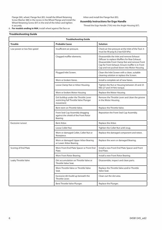
Troubleshooting Guide
Troubleshooting Guide
Trouble Probable Cause Solution
Low power or low free speed Insufficient air pressure. Check air line pressure at the Inlet of the Tool. It must be 90 psig (6.2 bar/620 kPa).
Clogged muffler elements. Disassemble the Inlet and remove ExhaustDiffuser to replace Mufflers for Rear Exhaust.Disassemble Front Clamp Nut and remove FrontCap for Front Exhaust. Ensure muffler is in FrontCap and not pushed down into Motor Housing.
Plugged Inlet Screen. Clean the Inlet Screen with a clean, suitable cleaning solution or replace the Screen.
Worn or broken Vanes. Install a complete set of new Vanes.
Loose Clamp Nut or Arbor Housing. Tighten the Nut or Housing between 20 and 25 ftlb (27 and 34 Nm) torque.
Worn or broken Motor Housing Replace the Motor Housing.
Grit buildup under the Throttle Lever restricting full Throttle Valve Plunger movement
Remove the Throttle Lever and clean the groove in the Motor Housing.
Bent stem on Throttle Valve. Replace the Throttle Valve.
Front Seal Cup Assembly dragging against the shield of the Front Rotor Bearing
Reposition the Front Seal Cup Assembly.
Excessive runout Bent Arbor. Replace the Arbor.
Loose Collet Nut. Tighten the Collet Nut until snug.
Worn or damaged Collet, Collet Nut or Nosepiece.
Replace the damaged component and retest.
Worn or damaged Upper Arbor Bearing or Lower Arbor Bearing.
Replace the worn or damaged Bearing.
Scoring of End Plate Worn Front End Plate Spacer or Front EndPlate.
Install a new Front End Plate Spacer and Front End Plate.
Worn Front Rotor Bearing. Install a new Front Rotor Bearing.
Leaky Throttle Valve Dirt accumulation on Throttle Valve or Throttle Valve Seat.
Disassemble, inspect and clean parts.
Worn Throttle Valve or Throttle Valve Seat.
Replace the Throttle Valve and/or Throttle Valve Seat.
Excessive dirt build-up beneath the Throttle Lever.
Clean out the slot area.
Bent Throttle Valve Plunger. Replace the Plunger.

04581245_ed2 7
Trouble Probable Cause Solution
Exhausts at wrong direction Incorrect orientation of the Flow Guide. Reverse the Flow Guide inside the Motor Housing.
Front Rotor Bearing runs hot Incorrect installation of the Front Seal Cup Assembly.
Reposition the Front Seal Cup Assembly flush with the face of the Front End Plate Spacer.
Front End Plate Spacer rubbing the bore of the Front End Plate.
Replace the Front End Plate and Front End Plate Spacer combination.
Incorrect Front Rotor Bearing installation orientation.
If a black stain or black hashmarks are not visibleon the face of the Bearing when it is assembledwith the End Plate and Rotor, the Bearing isinstalled backwards. If possible, remove theBearing and install it correctly or replace theBearing.
Slow tool idle Bent or leaky Throttle Valve. Replace the Throttle Valve.
Rough operation/vibration Improper lubrication or dirt buildup. Disassemble the Tool and clean in a suitable cleaning solution. Assemble the Tool and inject 3 cm3 of the recommended oil into the Inlet and run the tool long enough to coat the internal parts with the oil.
Worn or broken Rear Rotor Bearing or Front Rotor Bearing.
Replace the worn or broken Bearings. Examine the Front End Plate, Front End Plate Spacer Front Seal Cup Assembly and Rear Rotor Bearing Spacers and replace any damaged parts. If the rear end plate is damaged, replace the Rotor.
Worn or broken Upper Arbor Bearing or Lower Arbor Bearing.
Replace the worn or broken Bearing.
Worn or broken Bevel Gear or Bevel Pinion.
Examine the Bevel Gear and Bevel Pinion. If either is worn or damaged, replace both the Gear and the Pinion because they are a matched set and must not be used separately.
Related DocumentationFor additional information refer to:
Air Grinder Product Safety Information Manual Form 04584959.
Air Die Grinder Safety Information Form 04580288.
Air Sander Safety Information Form 04580387.
Product Information Manual Form 04581211, Form 04581799, Form 04581195 and Form 04581203.
Parts Information Manual Form 04581237.
Manuals can be downloaded from ingersollrandproducts.com

ingersollrandproducts.com
© 2014 Ingersoll Rand