Embed Size (px)
Citation preview
MAGNUM® PRO 250/350/450 AND 550
OPERATORʼS MANUAL
IM10009-BJanuary, 2011
Safety Depends on YouLincoln arc welding and cuttingequipment is designed and builtwith safety in mind. However,your overall safety can beincreased by proper installation... and thoughtful operation onyour part. DO NOT INSTALL,OPERATE OR REPAIR THISEQUIPMENT WITHOUT READ-ING THIS MANUAL AND THESAFETY PRECAUTIONS CON-TAINED THROUGHOUT. And,most importantly, think before youact and be careful.
Models K2651-[ ], K2652-[ ], K2653-[ ] and K2655-[ ]
• Sales and Service through Subsidiaries and Distributors Worldwide •
Cleveland, Ohio 44117-1199 U.S.A. TEL: 216.481.8100 FAX: 216.486.1751 WEB SITE: www.lincolnelectric.com
• World's Leader in Welding and Cutting Products •
Copyright © Lincoln Global Inc.
FOR ENGINEpowered equipment.
1.a. Turn the engine off before troubleshooting and maintenancework unless the maintenance work requires it to be running.
____________________________________________________1.b. Operate engines in open, well-ventilated
areas or vent the engine exhaust fumes outdoors.
____________________________________________________1.c. Do not add the fuel near an open flame weld-
ing arc or when the engine is running. Stopthe engine and allow it to cool before refuel-ing to prevent spilled fuel from vaporizing oncontact with hot engine parts and igniting. Donot spill fuel when filling tank. If fuel is spilled,wipe it up and do not start engine until fumeshave been eliminated.
____________________________________________________1.d. Keep all equipment safety guards, covers and devices in posi-
tion and in good repair.Keep hands, hair, clothing and toolsaway from V-belts, gears, fans and all other moving partswhen starting, operating or repairing equipment.
____________________________________________________
1.e. In some cases it may be necessary to remove safetyguards to perform required maintenance. Removeguards only when necessary and replace them when themaintenance requiring their removal is complete.Always use the greatest care when working near movingparts.
___________________________________________________1.f. Do not put your hands near the engine fan.
Do not attempt to override the governor oridler by pushing on the throttle control rodswhile the engine is running.
___________________________________________________1.g. To prevent accidentally starting gasoline engines while
turning the engine or welding generator during maintenancework, disconnect the spark plug wires, distributor cap ormagneto wire as appropriate.
iSAFETYi
ARC WELDING CAN BE HAZARDOUS. PROTECT YOURSELF AND OTHERS FROM POSSIBLE SERIOUS INJURY OR DEATH.KEEP CHILDREN AWAY. PACEMAKER WEARERS SHOULD CONSULT WITH THEIR DOCTOR BEFORE OPERATING.
Read and understand the following safety highlights. For additional safety information, it is strongly recommended that youpurchase a copy of “Safety in Welding & Cutting - ANSI Standard Z49.1” from the American Welding Society, P.O. Box 351040,Miami, Florida 33135 or CSA Standard W117.2-1974. A Free copy of “Arc Welding Safety” booklet E205 is available from theLincoln Electric Company, 22801 St. Clair Avenue, Cleveland, Ohio 44117-1199.
BE SURE THAT ALL INSTALLATION, OPERATION, MAINTENANCE AND REPAIR PROCEDURES AREPERFORMED ONLY BY QUALIFIED INDIVIDUALS.
WARNING
ELECTRIC AND MAGNETIC FIELDSmay be dangerous
2.a. Electric current flowing through any conductor causes localized Electric and Magnetic Fields (EMF). Welding current creates EMF fields around welding cables and welding machines.
2.b. EMF fields may interfere with some pacemakers, andwelders having a pacemaker should consult their physicianbefore welding.
2.c. Exposure to EMF fields in welding may have other healtheffects which are now not known.
2.d. All welders should use the following procedures in order tominimize exposure to EMF fields from the welding circuit:
2.d.1. Route the electrode and work cables together - Securethem with tape when possible.
2.d.2. Never coil the electrode lead around your body.
2.d.3. Do not place your body between the electrode andwork cables. If the electrode cable is on your right side, the work cable should also be on your right side.
2.d.4. Connect the work cable to the workpiece as close aspossible to the area being welded.
2.d.5. Do not work next to welding power source.
1.h. To avoid scalding, do not remove theradiator pressure cap when the engine ishot.
CALIFORNIA PROPOSITION 65 WARNINGS
Diesel engine exhaust and some of its constituentsare known to the State of California to cause can-cer, birth defects, and other reproductive harm.
The engine exhaust from this product containschemicals known to the State of California to causecancer, birth defects, or other reproductive harm.
The Above For Diesel Engines The Above For Gasoline Engines
iiSAFETYii
ARC RAYS can burn.4.a. Use a shield with the proper filter and cover
plates to protect your eyes from sparks andthe rays of the arc when welding or observingopen arc welding. Headshield and filter lensshould conform to ANSI Z87. I standards.
4.b. Use suitable clothing made from durable flame-resistantmaterial to protect your skin and that of your helpers fromthe arc rays.
4.c. Protect other nearby personnel with suitable, non-flammablescreening and/or warn them not to watch the arc nor exposethemselves to the arc rays or to hot spatter or metal.
ELECTRIC SHOCK can kill.3.a. The electrode and work (or ground) circuits
are electrically “hot” when the welder is on.Do not touch these “hot” parts with your bareskin or wet clothing. Wear dry, hole-freegloves to insulate hands.
3.b. Insulate yourself from work and ground using dry insulation.Make certain the insulation is large enough to cover your fullarea of physical contact with work and ground.
In addition to the normal safety precautions, if weldingmust be performed under electrically hazardousconditions (in damp locations or while wearing wetclothing; on metal structures such as floors, gratings orscaffolds; when in cramped positions such as sitting,kneeling or lying, if there is a high risk of unavoidable oraccidental contact with the workpiece or ground) usethe following equipment:
• Semiautomatic DC Constant Voltage (Wire) Welder.• DC Manual (Stick) Welder.• AC Welder with Reduced Voltage Control.
3.c. In semiautomatic or automatic wire welding, the electrode,electrode reel, welding head, nozzle or semiautomaticwelding gun are also electrically “hot”.
3.d. Always be sure the work cable makes a good electricalconnection with the metal being welded. The connectionshould be as close as possible to the area being welded.
3.e. Ground the work or metal to be welded to a good electrical(earth) ground.
3.f. Maintain the electrode holder, work clamp, welding cable andwelding machine in good, safe operating condition. Replacedamaged insulation.
3.g. Never dip the electrode in water for cooling.
3.h. Never simultaneously touch electrically “hot” parts ofelectrode holders connected to two welders because voltagebetween the two can be the total of the open circuit voltageof both welders.
3.i. When working above floor level, use a safety belt to protectyourself from a fall should you get a shock.
3.j. Also see Items 6.c. and 8.
FUMES AND GASEScan be dangerous.5.a. Welding may produce fumes and gases
hazardous to health. Avoid breathing thesefumes and gases. When welding, keepyour head out of the fume. Use enoughventilation and/or exhaust at the arc to keep
fumes and gases away from the breathing zone. Whenwelding with electrodes which require specialventilation such as stainless or hard facing (seeinstructions on container or MSDS) or on lead orcadmium plated steel and other metals or coatingswhich produce highly toxic fumes, keep exposure aslow as possible and within applicable OSHA PEL and ACGIH TLV limits using local exhaust or mechanical ven-tilation. In confined spaces or in some circumstances,outdoors, a respirator may be required. Additional pre-cautions are also required when welding on galvanizedsteel.
5. b. The operation of welding fume control equipment is affectedby various factors including proper use and positioning of theequipment, maintenance of the equipment and the specificwelding procedure and application involved. Worker expo-sure level should be checked upon installation and periodi-cally thereafter to be certain it is within applicable OSHA PELand ACGIH TLV limits.
5.c. Do not weld in locations near chlorinated hydrocarbon vaporscoming from degreasing, cleaning or spraying operations.The heat and rays of the arc can react with solvent vapors toform phosgene, a highly toxic gas, and other irritating prod-ucts.
5.d. Shielding gases used for arc welding can displace air andcause injury or death. Always use enough ventilation,especially in confined areas, to insure breathing air is safe.
5.e. Read and understand the manufacturerʼs instructions for thisequipment and the consumables to be used, including thematerial safety data sheet (MSDS) and follow youremployerʼs safety practices. MSDS forms are available fromyour welding distributor or from the manufacturer.
5.f. Also see item 1.b.
iiiSAFETYiii
FOR ELECTRICALLYpowered equipment.
8.a. Turn off input power using the disconnectswitch at the fuse box before working onthe equipment.
8.b. Install equipment in accordance with the U.S. NationalElectrical Code, all local codes and the manufacturerʼsrecommendations.
8.c. Ground the equipment in accordance with the U.S. NationalElectrical Code and the manufacturerʼs recommendations.
CYLINDER may explodeif damaged.7.a. Use only compressed gas cylinders
containing the correct shielding gas for theprocess used and properly operatingregulators designed for the gas and
pressure used. All hoses, fittings, etc. should be suitable forthe application and maintained in good condition.
7.b. Always keep cylinders in an upright position securelychained to an undercarriage or fixed support.
7.c. Cylinders should be located:• Away from areas where they may be struck or subjected tophysical damage.
• A safe distance from arc welding or cutting operations andany other source of heat, sparks, or flame.
7.d. Never allow the electrode, electrode holder or any otherelectrically “hot” parts to touch a cylinder.
7.e. Keep your head and face away from the cylinder valve outletwhen opening the cylinder valve.
7.f. Valve protection caps should always be in place and handtight except when the cylinder is in use or connected foruse.
7.g. Read and follow the instructions on compressed gascylinders, associated equipment, and CGA publication P-l,“Precautions for Safe Handling of Compressed Gases inCylinders,” available from the Compressed Gas Association1235 Jefferson Davis Highway, Arlington, VA 22202.
WELDING and CUTTINGSPARKS cancause fire or explosion.6.a. Remove fire hazards from the welding area.
If this is not possible, cover them to preventthe welding sparks from starting a fire.
Remember that welding sparks and hotmaterials from welding can easily go through small cracksand openings to adjacent areas. Avoid welding nearhydraulic lines. Have a fire extinguisher readily available.
6.b. Where compressed gases are to be used at the job site,special precautions should be used to prevent hazardoussituations. Refer to “Safety in Welding and Cutting” (ANSIStandard Z49.1) and the operating information for theequipment being used.
6.c. When not welding, make certain no part of the electrodecircuit is touching the work or ground. Accidental contact cancause overheating and create a fire hazard.
6.d. Do not heat, cut or weld tanks, drums or containers until theproper steps have been taken to insure that such procedureswill not cause flammable or toxic vapors from substancesinside. They can cause an explosion even though they havebeen “cleaned”. For information, purchase “RecommendedSafe Practices for the Preparation for Welding and Cutting ofContainers and Piping That Have Held HazardousSubstances”, AWS F4.1 from the American Welding Society(see address above).
6.e. Vent hollow castings or containers before heating, cutting orwelding. They may explode.
6.f. Sparks and spatter are thrown from the welding arc. Wear oilfree protective garments such as leather gloves, heavy shirt,cuffless trousers, high shoes and a cap over your hair. Wearear plugs when welding out of position or in confined places.Always wear safety glasses with side shields when in awelding area.
6.g. Connect the work cable to the work as close to the weldingarea as practical. Work cables connected to the buildingframework or other locations away from the welding areaincrease the possibility of the welding current passingthrough lifting chains, crane cables or other alternate circuits.This can create fire hazards or overheat lifting chains orcables until they fail.
6.h. Also see item 1.c.
6.I. Read and follow NFPA 51B “ Standard for Fire PreventionDuring Welding, Cutting and Other Hot Work”, available fromNFPA, 1 Batterymarch Park, PO box 9101, Quincy, Ma022690-9101.
6.j. Do not use a welding power source for pipe thawing.
Refer to http://www.lincolnelectric.com/safety for additional safety information.
ivSAFETYiv
PRÉCAUTIONS DE SÛRETÉPour votre propre protection lire et observer toutes les instructionset les précautions de sûreté specifiques qui parraissent dans cemanuel aussi bien que les précautions de sûreté générales suiv-antes:
Sûreté Pour Soudage A LʼArc1. Protegez-vous contre la secousse électrique:
a. Les circuits à lʼélectrode et à la piéce sont sous tensionquand la machine à souder est en marche. Eviter toujourstout contact entre les parties sous tension et la peau nueou les vétements mouillés. Porter des gants secs et sanstrous pour isoler les mains.
b. Faire trés attention de bien sʼisoler de la masse quand onsoude dans des endroits humides, ou sur un plancher met-allique ou des grilles metalliques, principalement dans les positions assis ou couché pour lesquelles une grandepartie du corps peut être en contact avec la masse.
c. Maintenir le porte-électrode, la pince de masse, le câble desoudage et la machine à souder en bon et sûr état defonc-tionnement.
d.Ne jamais plonger le porte-électrode dans lʼeau pour lerefroidir.
e. Ne jamais toucher simultanément les parties sous tensiondes porte-électrodes connectés à deux machines à soud-er parce que la tension entre les deux pinces peut être letotal de la tension à vide des deux machines.
f. Si on utilise la machine à souder comme une source decourant pour soudage semi-automatique, ces precautionspour le porte-électrode sʼapplicuent aussi au pistolet desoudage.
2. Dans le cas de travail au dessus du niveau du sol, se protégercontre les chutes dans le cas ou on recoit un choc. Ne jamaisenrouler le câble-électrode autour de nʼimporte quelle partiedu corps.
3. Un coup dʼarc peut être plus sévère quʼun coup de soliel,donc:
a. Utiliser un bon masque avec un verre filtrant appropriéainsi quʼun verre blanc afin de se protéger les yeux du ray-onnement de lʼarc et des projections quand on soude ouquand on regarde lʼarc.
b. Porter des vêtements convenables afin de protéger lapeau de soudeur et des aides contre le rayonnement delʻarc.
c. Protéger lʼautre personnel travaillant à proximité ausoudage à lʼaide dʼécrans appropriés et non-inflammables.
4. Des gouttes de laitier en fusion sont émises de lʼarc desoudage. Se protéger avec des vêtements de protection libresde lʼhuile, tels que les gants en cuir, chemise épaisse, pan-talons sans revers, et chaussures montantes.
5. Toujours porter des lunettes de sécurité dans la zone desoudage. Utiliser des lunettes avec écrans lateraux dans leszones où lʼon pique le laitier.
6. Eloigner les matériaux inflammables ou les recouvrir afin deprévenir tout risque dʼincendie dû aux étincelles.
7. Quand on ne soude pas, poser la pince à une endroit isolé dela masse. Un court-circuit accidental peut provoquer unéchauffement et un risque dʼincendie.
8. Sʼassurer que la masse est connectée le plus prés possible dela zone de travail quʼil est pratique de le faire. Si on place lamasse sur la charpente de la construction ou dʼautres endroitséloignés de la zone de travail, on augmente le risque de voirpasser le courant de soudage par les chaines de levage,câbles de grue, ou autres circuits. Cela peut provoquer desrisques dʼincendie ou dʼechauffement des chaines et descâbles jusquʼà ce quʼils se rompent.
9. Assurer une ventilation suffisante dans la zone de soudage.Ceci est particuliérement important pour le soudage de tôlesgalvanisées plombées, ou cadmiées ou tout autre métal quiproduit des fumeés toxiques.
10. Ne pas souder en présence de vapeurs de chlore provenantdʼopérations de dégraissage, nettoyage ou pistolage. Lachaleur ou les rayons de lʼarc peuvent réagir avec les vapeursdu solvant pour produire du phosgéne (gas fortement toxique)ou autres produits irritants.
11. Pour obtenir de plus amples renseignements sur la sûreté, voirle code “Code for safety in welding and cutting” CSA StandardW 117.2-1974.
PRÉCAUTIONS DE SÛRETÉ POURLES MACHINES À SOUDER ÀTRANSFORMATEUR ET ÀREDRESSEUR
1. Relier à la terre le chassis du poste conformement au code delʼélectricité et aux recommendations du fabricant. Le dispositifde montage ou la piece à souder doit être branché à unebonne mise à la terre.
2. Autant que possible, Iʼinstallation et lʼentretien du poste seronteffectués par un électricien qualifié.
3. Avant de faires des travaux à lʼinterieur de poste, la debranch-er à lʼinterrupteur à la boite de fusibles.
4. Garder tous les couvercles et dispositifs de sûreté à leurplace.

vv
Thank You for selecting a QUALITY product by Lincoln Electric. We want youto take pride in operating this Lincoln Electric Company product •••as much pride as we have in bringing this product to you!
Read this Operators Manual completely before attempting to use this equipment. Save this manual and keep ithandy for quick reference. Pay particular attention to the safety instructions we have provided for your protection.The level of seriousness to be applied to each is explained below:
WARNINGThis statement appears where the information must be followed exactly to avoid serious personal injury or loss of life.
This statement appears where the information must be followed to avoid minor personal injury or damage to this equipment.
CAUTION
On-Line Product Registration- Register your machine with Lincoln Electric either via fax or over the Internet.
• For faxing: Complete the form on the back of the warranty statement included in the literature packetaccompanying this machine and fax the form per the instructions printed on it.
• For On-Line Registration: Go to our WEB SITE at www.lincolnelectric.com. Choose “Support” and then “RegisterYour Product”. Please complete the form and submit your registration.
CUSTOMER ASSISTANCE POLICYThe business of The Lincoln Electric Company is manufacturing and selling high quality welding equipment, consumables, and cutting equip-ment. Our challenge is to meet the needs of our customers and to exceed their expectations. On occasion, purchasers may ask Lincoln Electricfor advice or information about their use of our products. We respond to our customers based on the best information in our possession at thattime. Lincoln Electric is not in a position to warrant or guarantee such advice, and assumes no liability, with respect to such information oradvice. We expressly disclaim any warranty of any kind, including any warranty of fitness for any customerʼs particular purpose, with respectto such information or advice. As a matter of practical consideration, we also cannot assume any responsibility for updating or correcting anysuch information or advice once it has been given, nor does the provision of information or advice create, expand or alter any warranty withrespect to the sale of our products.
Lincoln Electric is a responsive manufacturer, but the selection and use of specific products sold by Lincoln Electric is solely within the controlof, and remains the sole responsibility of the customer. Many variables beyond the control of Lincoln Electric affect the results obtained inapplying these types of fabrication methods and service requirements.
Subject to Change – This information is accurate to the best of our knowledge at the time of printing. Please refer to www.lincolnelectric.comfor any updated information.
Please Examine Carton and Equipment For Damage ImmediatelyWhen this equipment is shipped, title passes to the purchaser upon receipt by the carrier. Consequently, Claimsfor material damaged in shipment must be made by the purchaser against the transportation company at thetime the shipment is received.
Please record your equipment identification information below for future reference. This information can be foundon your equipment nameplate or the product carton label.
Model Name and Sales Spec Number (K-xxx) _____________________________________
Date of Purchase __________________________________
Whenever you request replacement parts for or information on this equipment always supply the information youhave recorded above.

TABLE OF CONTENTSPage
General Description ..................................................................................................... Section A_______________________________________________________________________________________
Installation .................................................................................................................... Section BConnector Kit Installation to Gun Cable ............................................................................. B-1
K466-1 &-8 Installation ............................................................................................... B-1K466-2 Installation ...................................................................................................... B-1K466-3 Installation ...................................................................................................... B-1K466-4 Installation ...................................................................................................... B-1K466-5 Installation ...................................................................................................... B-2K466-6, 7, 9 & 10 Installation ..................................................................................... B-2
Liner Installation ................................................................................................................. B-2Contact Tip and Gas Nozzle Installation ............................................................................ B-3Connection to Feeder ........................................................................................................ B-3
Connection to Lincoln Feeders ................................................................................... B-3Connection to Tweco Adapted Feeders ...................................................................... B-3Connection to Miller Feeders ...................................................................................... B-3Connection to Hobart Feeders .................................................................................... B-4Connection to L-Tec Adapted Feeders ....................................................................... B-4Connection to Lincoln Wirematic, Hobart Series 2000 or SP100T Feeders .............. B-4Connection to 10 Series Feeders ............................................................................... B-5
_______________________________________________________________________________________
Operation ...................................................................................................................... Section CElectrodes and Equipment ................................................................................................. C-1Making a Weld ................................................................................................................... C-1Avoiding Wire Feeding Problems ...................................................................................... C-1
_______________________________________________________________________________________
Maintenance .................................................................................................................. Section DRemoval, Installation and Trimming Instructions for MAGNUM® Liners ........................... D-1Gun Tubes and Nozzles .................................................................................................... D-1Gun Cables ........................................................................................................................ D-1
Cable Cleaning ........................................................................................................... D-1Cable Repair All Models ..................................................................................................... D-1
Gun Tube End Repair .................................................................................................. D-1Wire Feeder End Repair .............................................................................................. D-3
_______________________________________________________________________________________
Troubleshooting ........................................................................................................... Section E_______________________________________________________________________________________
Parts Lists ....................................................................................................................... P202-AF_______________________________________________________________________________________
vivi
GENERAL DESCRIPTION
MAGNUM® PRO 250, 350, 450 & 550 AMP
A-1A-1
GENERAL DESCRIPTION
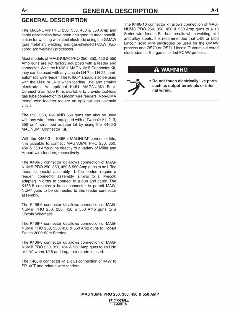
The MAGNUM® PRO 250, 350, 450 & 550 Amp andcable assemblies have been designed to meet specifi-cation for welding with steel electrode using the GMAW(gas metal arc welding) and gas-shielded FCAW (flux-cored arc welding) processes.
Most models of MAGNUM® PRO 250, 350, 450 & 550Amp guns are not factory equipped with a feeder endconnector. With the K466-1 MAGNUM® Connector Kit,they can be used with any Lincoln LN-7 or LN-25 semi-automatic wire feeder. The K466-1 should also be usedwith the LN-8 or LN-9 when feeding .052 and smallerelectrodes. An optional K481 MAGNUM® Fast-Connect Gas Tube Kit is available to provide tool-lessgas tube connection to Lincoln wire feeders. Non-GMAmodel wire feeders require an optional gas solenoidvalve.
The 250, 350, 450 AND 550 guns can also be usedwith any wire feeder equipped with a Tweco® #1, 2, 3,350 or 4 wire feed adapter kit by using the K466-2MAGNUM® Connector Kit.
With the K466-3 or K466-4 MAGNUM® connector kits,it is possible to connect MAGNUM® PRO 250, 350,450 & 550 Amp guns directly to a variety of Miller andHobart wire feeders, respectively.
The K466-5 connector kit allows connection of MAG-NUM® PRO 250, 350, 450 & 550 Amp guns to an L Tecfeeder connector assembly. L-Tec feeders require afeeder connector assembly (similar to a Tweco®adapter) in order to connect to a gun and cable. TheK466-5 contains a brass connector to permit MAG-NUM® guns to be connected to this feeder connectorassembly.
The K466-6 connector kit allows connection of MAG-NUM® PRO 250, 350, 450 & 550 Amp guns to aLincoln Wirematic.
The K466-7 connector kit allows connection of MAG-NUM® PRO 250, 350, 450 & 550 Amp guns to HobartSeries 2000 Wire Feeders.
The K466-8 connector kit allows connection of MAG-NUM® PRO 250, 350, 450 & 550 Amp guns to an LN8or LN9 when 1/16 and larger electrode is used.
The K466-9 connector kit allows connection of K497 toSP100T and related wire feeders.
The K466-10 connector kit allows connection of MAG-NUM® PRO 250, 350, 450 & 550 Amp guns to a 10Series wire feeder. For best results when welding mildand alloy steels, it is recommended that L-50 or L-56Lincoln solid wire electrodes be used for the GMAWprocess and OS70 or OS71 Lincoln Outershield coredelectrodes for the gas-shielded FCAW process.
• Do not touch electrically live partssuch as output terminals or inter-nal wiring.
------------------------------------------------------------------------
WARNING

GENERAL DESCRIPTION
MAGNUM® PRO 250, 350, 450 & 550 AMP
A-2A-2
MAGNUM® PRO 250 (250 amperes AT 100% DUTY CYCLE WITH CO2 GAS250 amperes AT 100% DUTY CYCLE WITH MIXED GAS)
DescriptionGun Contact Tips Gas
Product Cable Wire Size Standard Diffuser Gas Cable Gun TubeNumber Length (m) in. (mm) Duty Assembly Nozzle Insulator Liner 60°
K2651-1 10 ft. 035 (0.9)(3.1) 5/64 (2.0)
K2651-2 15 ft .035 (0.9)(4.5) 5/64 (2.0)
K2651-2-6-45 15 ft. .035 (0.9) KP2744-035 KP2746-1 KP2742-1-62R KP2773-2 KP44-3545-15 KP2866-60(4.5) 5/64 (2.0) -045
K2651-3 20 ft .035 (0.9)(6.1) 5/64 (2.0)
K2651-4 25 ft .035 (0.9)(7.6) 5/64 (2.0)
MAGNUM® PRO 350 (350 amperes AT 100% DUTY CYCLE WITH CO2 GAS275 amperes AT 100% DUTY CYCLE WITH MIXED GAS)
DescriptionGun Contact Tips Gas
Product Cable Wire Size Standard Diffuser Gas Cable Gun TubeNumber Length (m) in. (mm) Duty Assembly Nozzle Insulator Liner 60°
K2652-1 10 ft. .035 (0.9)(3.1) 5/64 (2.0)
K2652-2 15 ft .035 (0.9)(4.5) 5/64 (2.0)
KP2744-035 KP2746-1 KP2742-1-62R KP2773-2 KP44-3545-15 KP2867-60K2652-2-10-45 15 ft. .035 (0.9) -045
(4.5) 5/64 (2.0)
K2652-3 20 ft .035 (0.9)(6.1) 5/64 (2.0)
K2652-4 25 ft .035 (0.9)(7.6) 5/64 (2.0)

A-3GENERAL DESCRIPTION
MAGNUM® PRO 250, 350, 450 AND 550
A-3
MAGNUM® PRO 550 (550 amperes AT 100% DUTY CYCLE WITH CO2 GAS375 amperes AT 100% DUTY CYCLE WITH MIXED GAS)
MAGNUM® PRO 450 (450 amperes AT 100% DUTY CYCLE WITH CO2 GAS325 amperes AT 100% DUTY CYCLE WITH MIXED GAS)
DescriptionGun Contact Tips Gas
Product Cable Wire Size Standard Diffuser Gas Cable Gun TubeNumber Length (m) in. (mm) Duty Assembly Nozzle Insulator Liner 60°
K2653-1 10 ft. .035 (0.9)(3.1) 5/64 (2.0)
K2653-2 15 ft. .035 (0.9)(4.5) 5/64 (2.0)
KP2745-035 KP2747-1 KP2743-1-62R KP2773-1 KP44-3545-15 KP2868-6K2653-2-10-45 15 ft. .035 (0.9) -045
(4.5) 5/64 (2.0)
K2653-3 20 ft. .035 (0.9)(6.1) 5/64 (2.0)
K2653-4 25 ft. .035 (0.9)(7.6) 5/64 (2.0)
DescriptionGun Contact Tips Gas
Product Cable Wire Size Standard Diffuser Gas Cable Gun TubeNumber Length (m) in. (mm) Duty Assembly Nozzle Insulator Liner 60°
K2655-1 10 ft. .035 (0.9)(3.1) 1/8 (3.2)
K2655-2 15 ft. .035 (0.9)(4.5) 1/8 (3.2) KP2745-052 KP2747-1 KP2743-1-62R KP2773-1 KP45-116-15 KP2869-60
-116K2655-3 20 ft. .035 (0.9)
(6.1) 1/8 (3.2)
K2655-4 25 ft. .035 (0.9)(7.6) 1/8 (3.2)

INSTALLATION
MAGNUM® PRO 250, 350, 450 & 550 AMP
Read this entire installation section before youstart installation.
SAFETY PRECAUTIONS
ELECTRIC SHOCK can kill.
• Do not touch electrically live partssuch as output terminals orinternal wiring.
• Insulate yourself from the workand ground.
• Always wear dry insulating gloves.------------------------------------------------------------------------Only qualified personnel should install, use orservice this equipment
CONNECTOR KIT INSTALLATION TO GUN CABLE
Most models of MAGNUM® PRO 250, 350, 450 & 550Amp gun cables are shipped as generic assembliesand must be assembled with a K466 connector kit (SeeREPLACEMENT PARTS P-202 series, section Chart Efor proper kit).
K466-1& -8 INSTALLATION (For Lincoln Feeders)
a. Remove brass cable connector and insulation tube(see Figure B.1) from the K466-1 kit. Slide the insu-lation tube onto the connector from the threadedend and screw it onto the feeder end of the guncable. Tighten the connection with the wrench pro-vided.
b. Remove the molded gas plug fitting on the side ofthe feeder end handle and replace it with the barbedbrass fitting provided in the kit. The included wrenchwill fit both the gas plug and barbed fitting.
c. Attach the round connector of the gun control cableprovided to the trigger connector on the front of theLincoln feeder. (NOTE: Both the plug and socketare keyed and must be properly oriented.)
d. Place one tubing clamp onto each end of the flexi-ble tubing provided, approximately 2” (51 mm) infrom each end. Slide one end of the tubing onto thebarbed connector on the feeder end cable handle(step b) and move the clamp down near the end ofthe tube to ensure a good gas seal.
NOTE: An optional K481 MAGNUM® Fast-ConnectGas Tube Kit is available to provide tool-less gas tubeconnection to Lincoln wire feeders. Install per theinstructions sent with the kit.
K466-2 INSTALLATION (For Tweco Adapted Feeders)
a. Remove brass cable connector (see Figure B.1)from the K466-2 kit and screw it onto the feeder endof the gun cable. Tighten the connection with thewrench provided.
b. Check that the molded gas plug fitting is sealing thegas fitting hole in the side of the feeder end handle.
K466-2 KIT
K466-3 INSTALLATION (For Miller Feeders)
a. Remove brass cable connector (see Figure B.1)from the K466-3 kit and screw it onto the feeder endof the gun cable. Tighten the connection with thewrench provided.
b. Check that the molded gas plug fitting is sealing thegas fitting hole in the side of the feeder end handle.
c. Attach the round connector of the gun control cableprovided to the trigger connector on the front of theMiller feeder.
K466-3 KIT
K466-4 INSTALLATION (For Hobart Feeders)
a. Remove brass cable connector (see Figure B.1)from the K466-4 kit and screw it onto the feeder endof the gun cable. Tighten the connection with thewrench provided.
WARNING
B-1B-1
K466-1 KIT
K466-8 KIT
INSTALLATION
MAGNUM® PRO 250, 350, 450 & 550 AMP
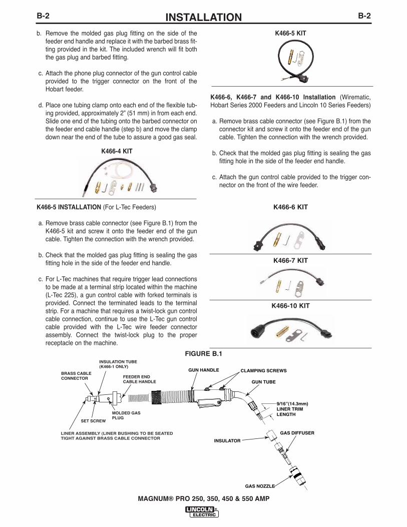
b. Remove the molded gas plug fitting on the side of thefeeder end handle and replace it with the barbed brass fit-ting provided in the kit. The included wrench will fit boththe gas plug and barbed fitting.
c. Attach the phone plug connector of the gun control cableprovided to the trigger connector on the front of theHobart feeder.
d. Place one tubing clamp onto each end of the flexible tub-ing provided, approximately 2” (51 mm) in from each end.Slide one end of the tubing onto the barbed connector onthe feeder end cable handle (step b) and move the clampdown near the end of the tube to assure a good gas seal.
K466-4 KIT
K466-5 INSTALLATION (For L-Tec Feeders)
a. Remove brass cable connector (see Figure B.1) from theK466-5 kit and screw it onto the feeder end of the guncable. Tighten the connection with the wrench provided.
b. Check that the molded gas plug fitting is sealing the gasfitting hole in the side of the feeder end handle.
c. For L-Tec machines that require trigger lead connectionsto be made at a terminal strip located within the machine(L-Tec 225), a gun control cable with forked terminals isprovided. Connect the terminated leads to the terminalstrip. For a machine that requires a twist-lock gun controlcable connection, continue to use the L-Tec gun controlcable provided with the L-Tec wire feeder connectorassembly. Connect the twist-lock plug to the properreceptacle on the machine.
K466-5 KIT
K466-6, K466-7 and K466-10 Installation (Wirematic,Hobart Series 2000 Feeders and Lincoln 10 Series Feeders)
a. Remove brass cable connector (see Figure B.1) from theconnector kit and screw it onto the feeder end of the guncable. Tighten the connection with the wrench provided.
b. Check that the molded gas plug fitting is sealing the gasfitting hole in the side of the feeder end handle.
c. Attach the gun control cable provided to the trigger con-nector on the front of the wire feeder.
K466-6 KIT
FIGURE B.1
GUN HANDLE CLAMPING SCREWS
GUN TUBE
GAS DIFFUSER
GAS NOZZLE
INSULATOR
INSULATION TUBE(K466-1 ONLY)
FEEDER ENDCABLE HANDLE
BRASS CABLECONNECTOR
MOLDED GASPLUG
SET SCREW
LINER ASSEMBLY (LINER BUSHING TO BE SEATEDTIGHT AGAINST BRASS CABLE CONNECTOR
9/16”(14.3mm)LINER TRIMLENGTH
B-2B-2
K466-7 KIT
K466-10 KIT

INSTALLATION LINER INSTALLATION AND TRIMMING INSTRUCTIONSInstallation of (KP44 and KP44N series liners)
a. Lay the gun and cable straight on a flat surface.
b. Make sure that the set screw in the connector endis backed out so as not to damage liner or linerbushing. Remove and save the gas nozzle, nozzleinsulator, and gas diffuser from the end of the guntube assembly.
c. Insert a new untrimmed liner into the connector endof the cable. Be sure the liner bushing is stenciledappropriately for the wire size being used.
d. NOTE: For liners KP44N and KP45NBefore fully seating the liner bushing, it will be nec-essary to trim the linerʼs inner tube flush with theliner bushing using a sharp blade. After trimming,remove any burrs from inner tube and insure thatthe opening is fully open.
For all K466 connector kits except K466-3 andK466-4, tighten the set screw in the cable connec-tor.
orFor K466-3 and K466-4, screw in the connector capprovided in the kit until it seats on the face of thebushing. Then insert the appropriate piece of linermaterial into the connector cap and tighten the setscrew. Three pieces of liner material are included inthese connector kits to help guide the electrodethrough the connector cap. The piece with thesmallest inner diameter is designed for .045” (1.2mm) maximum diameter electrode. The next largestdiameter is for 1/16” (1.6 mm) maximum diameterelectrode. The largest diameter piece of liner mate-rial is for 5/64” (2.0 mm) maximum diameter elec-trode.
e. Be sure the cable is straight and then trim the linerto the length shown in Figure B.1 (a gauge is includ-ed on the wrench provided with the connection kitfor gauging the cut-off length on 250, 350, 450 and550 amp gun tubes). Remove any burrs from theend of the liner.
f. Replace the Insulator 250, 350, 450 and 550.
g. Screw the gas diffuser onto the end of the gun tubeand tighten.
h. Replace the nozzle insulator and gas nozzle.
INSTALLATION OF M18732 SERIES LINERS FORFEEDING ALUMINUM ELECTRODE
1. Lay the gun out straight on a flat surface andremove the gas nozzle.
A. For all K466 except K466-3 and K466-4 connec-tions, back out the set screw in the connector endwith a 5/64 (2.0 mm) Allen wrench.
B. For all K466-3 and K466-4 connections: Removethe connector cap.
C. Back out the set screw in the diffuser for gunsthat have a set screw in the diffuser.
2. Remove the liner and insert a new untrimmed linerinto the connector end of the cable. Check that thecoils of the spring liner can be seen through theholes in the gas diffuser.
A. For all K466-3 and K466-4 connections: If theliner is going to be replaced with a different sizeliner, loosen the set screw on the connector capand replace the liner material with the correctsize.
3. Mark the liner 3/16" (5 mm) from the end of the linerguide or connector. Pull the liner partially out andcut off the liner at the mark using a sharp knife.
4. Screw the brass liner nipple onto the liner and fullyseat the liner busing into the liner guide or the con-nector.
A. For connector kits, except K466-3 and K466-4,tighten the set screw in the cable connector.
B. For K466-3 and K466-4, screw in the connectorcap.
5. Replace the Insulator.
6. Screw the gas diffuser onto the end of the gun tubeand tighten.
7. Replace the nozzle insulator and gas nozzle.
MAGNUM® PRO 250, 350, 450 & 550 AMP
B-3B-3
INSTALLATION
MAGNUM® PRO 250, 350, 450 & 550 AMP
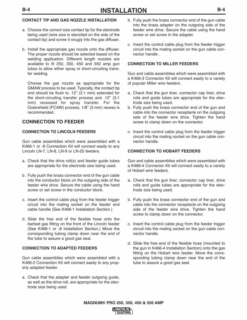
CONTACT TIP AND GAS NOZZLE INSTALLATION
a. Choose the correct size contact tip for the electrodebeing used (wire size is stenciled on the side of thecontact tip) and screw it snugly into the gas diffuser.
b. Install the appropriate gas nozzle onto the diffuser.The proper nozzle should be selected based on thewelding application. Different length nozzles areavailable to fit 250, 350, 450 and 550 amp guntubes to allow either spray or short-circuiting trans-fer welding.
Choose the gas nozzle as appropriate for theGMAW process to be used. Typically, the contact tipend should be flush to .12” (3.1 mm) extended forthe short-circuiting transfer process and .12” (3.1mm) recessed for spray transfer. For theOutershield (FCAW) process, 1/8” (3 mm) recess isrecommended.
CONNECTION TO FEEDER
CONNECTION TO LINCOLN FEEDERS
Gun cable assemblies which were assembled with aK466-1 or -8 Connection Kit will connect easily to anyLincoln LN-7, LN-8, LN-9 or LN-25 feeders.
a. Check that the drive roll(s) and feeder guide tubesare appropriate for the electrode size being used.
b. Fully push the brass connector end of the gun cableinto the conductor block on the outgoing side of thefeeder wire drive. Secure the cable using the handscrew or set screw in the conductor block.
c. Insert the control cable plug from the feeder triggercircuit into the mating socket on the feeder endcable handle (See K466-1 Installation Section.)
d. Slide the free end of the flexible hose onto thebarbed gas fitting on the front of the Lincoln feeder(See K466-1 or -8 Installation Section.) Move thecorresponding tubing clamp down near the end ofthe tube to assure a good gas seal.
CONNECTION TO ADAPTED FEEDERS
Gun cable assemblies which were assembled with aK466-2 Connection Kit will connect easily to any prop-erly adapted feeder.
a. Check that the adapter and feeder outgoing guide,as well as the drive roll, are appropriate for the elec-trode size being used.
b. Fully push the brass connector end of the gun cableinto the brass adapter on the outgoing side of thefeeder wire drive. Secure the cable using the handscrew or set screw in the adapter.
c. Insert the control cable plug from the feeder triggercircuit into the mating socket on the gun cable con-nector handle .
CONNECTION TO MILLER FEEDERS
Gun and cable assemblies which were assembled witha K466-3 Connector Kit will connect easily to a varietyof popular Miller wire feeders.
a. Check that the gun liner, connector cap liner, driverolls and guide tubes are appropriate for the elec-trode size being used.
b. Fully push the brass connector end of the gun andcable into the connector receptacle on the outgoingside of the feeder wire drive. Tighten the handscrew to clamp down on the connector.
c. Insert the control cable plug from the feeder triggercircuit into the mating socket on the gun cable con-nector handle.
CONNECTION TO HOBART FEEDERS
Gun and cable assemblies which were assembled witha K466-4 Connector Kit will connect easily to a varietyof Hobart wire feeders.
a. Check that the gun liner, connector cap liner, driverolls and guide tubes are appropriate for the elec-trode size being used.
b. Fully push the brass connector end of the gun andcable into the connector receptacle on the outgoingside of the feeder wire drive. Tighten the handscrew to clamp down on the connector.
c. Insert the control cable plug from the feeder triggercircuit into the mating socket on the gun cable con-nector handle.
d. Slide the free end of the flexible hose (mounted tothe gun in K466-4 Installation Section) onto the gasfitting on the Hobart wire feeder. Move the corre-sponding tubing clamp down near the end of thetube to assure a good gas seal.
B-4B-4
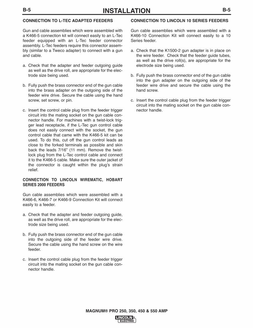
INSTALLATIONCONNECTION TO L-TEC ADAPTED FEEDERS
Gun and cable assemblies which were assembled witha K466-5 connection kit will connect easily to an L-Tecfeeder equipped with an L-Tec feeder connectorassembly. L-Tec feeders require this connector assem-bly (similar to a Tweco adapter) to connect with a gunand cable.
a. Check that the adapter and feeder outgoing guideas well as the drive roll, are appropriate for the elec-trode size being used.
b. Fully push the brass connector end of the gun cableinto the brass adapter on the outgoing side of thefeeder wire drive. Secure the cable using the handscrew, set screw, or pin.
c. Insert the control cable plug from the feeder triggercircuit into the mating socket on the gun cable con-nector handle. For machines with a twist-lock trig-ger lead receptacle, if the L-Tec gun control cabledoes not easily connect with the socket, the guncontrol cable that came with the K466-5 kit can beused. To do this, cut off the gun control leads asclose to the forked terminals as possible and skinback the leads 7/16” (11 mm). Remove the twist-lock plug from the L-Tec control cable and connectit to the K466-5 cable. Make sure the outer jacket ofthe connector is caught within the plugʼs strainrelief.
CONNECTION TO LINCOLN WIREMATIC, HOBARTSERIES 2000 FEEDERS
Gun cable assemblies which were assembled with aK466-6, K466-7 or K466-9 Connection Kit will connecteasily to a feeder.
a. Check that the adapter and feeder outgoing guide,as well as the drive roll, are appropriate for the elec-trode size being used.
b. Fully push the brass connector end of the gun cableinto the outgoing side of the feeder wire drive.Secure the cable using the hand screw on the wirefeeder.
c. Insert the control cable plug from the feeder triggercircuit into the mating socket on the gun cable con-nector handle.
CONNECTION TO LINCOLN 10 SERIES FEEDERS
Gun cable assemblies which were assembled with aK466-10 Connection Kit will connect easily to a 10Series feeder.
a. Check that the K1500-2 gun adapter is in place onthe wire feeder. Check that the feeder guide tubes,as well as the drive roll(s), are appropriate for theelectrode size being used.
b. Fully push the brass connector end of the gun cableinto the gun adapter on the outgoing side of thefeeder wire drive and secure the cable using thehand screw.
c. Insert the control cable plug from the feeder triggercircuit into the mating socket on the gun cable con-nector handle.
MAGNUM® PRO 250, 350, 450 & 550 AMP
B-5B-5
OPERATION
ELECTRODES AND EQUIPMENT
The MAGNUM® PRO 250, 350, 450 & 550 Amp gunsand cables have been designed for use with Lincoln L-50 and L-56, solid steel wire electrodes for the GMAWprocess and Lincoln Outershield cored electrodes forthe gas-shielded FCAW process. Refer to the appro-priate Lincoln Process and Procedure Guidelines forthe electrode used for information on recommendedelectrical and visible stickouts.
MAKING A WELD
Do not attempt to use this equipment until youhave thoroughly read all operating and mainte-nance manuals supplied with your machine. Theyinclude important safety precautions, detailedengine starting, operating and maintenanceinstructions and parts lists.
ELECTRIC SHOCK can kill.
• Do not touch electrically live partssuch as output terminals orinternal wiring.
• Insulate yourself from the workand ground.
• Always wear dry insulating gloves.------------------------------------------------------------------------
FUMES AND GASES can bedangerous.
• Keep your head out of fumes.
• Use ventilation or exhaust toremove fumes from breathing zone.
------------------------------------------------------------------------
WELDING SPARKS can cause fire orexplosion.
• Keep flammable material away.------------------------------------------------------------------------
ARC RAYS can burn.
• Wear eye, ear and body protection.
------------------------------------------------------------------------Only qualified personnel should operate thisequipment.
a. Check that the welding power source is on and thatthe shielding gas supply is set for the proper flowrate.
b. Position electrode over joint. End of the electrodeshould be slightly off the work.
c. Lower welding helmet. close gun trigger and beginwelding. Hold the gun so the contact tip to work dis-tance gives the correct electrical stickout asrequired for the procedure being used.
d. To stop welding, release the gun trigger and thenpull the gun away from the work after the arc goesout. Follow wire feeder instruction manual if using atrigger interlock circuit.
e. If the optional interlocking trigger is installed.
-With the trigger pulled in all the way, the trigger canbe slid forward into the interlock position.
-To release the interlock, squeeze the trigger andpull back.
AVOIDING WIRE FEEDING PROBLEMS
Wire feeding problems can be avoided by observingthe following gun handling procedures:
a. Do not kink or pull cable around sharp corners.
b. Keep the electrode cable as straight as possiblewhen welding or loading electrode through cable.
c. Avoid wrapping excess cable around handle or frontof wire feeder especially on longer 20 and 25 ft (6.1and 7.6 mm) length guns.
d. Do not allow dolly wheels or trucks to run overcables.
e. Keep cable clean by following maintenance instruc-tions.
f. Use only clean, rust-free electrode. The Lincolnelectrodes have proper surface lubrication.
g. Replace contact tip when the arc starts to becomeunstable or the contact tip end is fused or deformed.
MAGNUM® PRO 250, 350, 450 & 550 AMP
WARNING
C-1C-1
MAINTENANCE
REMOVAL, INSTALLATION AND TRIMMINGINSTRUCTIONS FOR MAGNUM® LINERS
NOTE: The variation in cable lengths prevents theinterchangeability of liners. Once a liner has been cutfor a particular gun, it should not be installed in anoth-er gun, unless it can meet the liner cut off lengthrequirement. Liners are shipped with the jacket of theliner extended the proper amount.
a. Remove the gas nozzle.
b. Remove the gas diffuser and insulator from gun.
c. Lay gun and cable out straight on a flat surface. Forall K466 except K466-3 and K466-4 Connections:
Loosen set screw located in the brass cable con-nector at the wire feeder end of the cable using thesame 5/64 (2.0 mm) Allen wrench. Pull liner out ofcable. (REFER TO FIGURE 1 IN INSTALLATIONFOR EACH)
<OR>
For K466-3 and K466-4 CONNECTIONS:
Remove the connector cap with the wrench provid-ed. Pull liner out of cable. If the liner is going to bereplaced with a different size liner, loosen set screwon the connector cap and remove piece of linermaterial.
d. For installation and trimming instructions for MAG-NUM® liners see “LINER INSTALLATION” inINSTALLATION section.
GUN TUBES AND NOZZLES
a. Replace worn contact tips as required.
b. Remove spatter from inside of gas nozzle and fromtip after each 10 minutes of arc time or as required.
c. To remove gun tube from gun, loosen 3 socket-head clamping screws in handle with an Allenwrench. Remove a knurled nut at the base of thehandle. Remove gas nozzle diffuser and nozzleinsulator, on the threaded gun tube from the cableassembly.
D. To reinstall, reverse procedure.
GUN CABLES
CABLE CLEANING
Clean cable liner after using approximately 300pounds (136 kg) of electrode. Remove the cable fromthe wire feeder and lay it out straight on the floor.Remove the contact tip from the gun. Using an air hoseand only partial pressure, gently blow out the cableliner from the gas diffuser end.
Excessive pressure at the start may cause the dirtto form a plug.------------------------------------------------------------------------Flex the cable over its entire length and again blow outthe cable. Repeat this procedure until no further dirtcomes out.
CABLE REPAIR (ALL K2646-[ ], K2647-[ ],K2649-[ ], K2650- [ ], K2651[ ], K2652-[ ],K2653-[ ] and K2655-[ ] MODELS)
The MAGNUM® PRO 250, 350, 450 & 550 Amp gunsfeature the use of repairable cable connectors. If thecable ever gets severely damaged. it may be cut short-er and repaired by the user. Repair cables as follows:
GUN TUBE END REPAIR (Requires 2 S19492-2Terminals)
a. Remove the cable liner per Removal, Installationand Trimming Instructions.
b. Remove the gun tube per Gun Tubes and NozzlesSection.
c. Remove three screws from the gun handle, removethe knurled nut separate the two halves, andremove the cable from the handle along with thetrigger assembly.
d. Remove gun tube connector from cable byunscrewing connector nut from gun tube connector.If the cable inner tube is difficult to remove from theconnector assembly, carefully slit it lengthwise witha knife up to the copper connector.
e. Uncouple the strain relief by pushing its outer hous-ing toward the middle of the cable. Move the strainrelief and the cable boot toward the middle of thecable, past the damaged section.
f. Cut off the damaged section of cable and strip off
MAGNUM® PRO 250, 350, 450 & 550 AMP
CAUTION
D-1D-1
MAINTENANCE
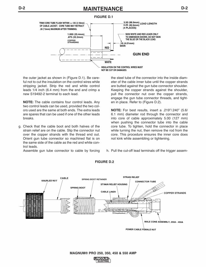
the outer jacket as shown in (Figure D.1). Be care-ful not to cut the insulation on the control wires whilestripping jacket. Strip the red and white controlleads 1/4 inch (6.4 mm) from the end and crimp anew S19492-2 terminal to each lead.
NOTE: The cable contains four control leads. Anytwo control leads can be used, provided the two col-ors used are the same at both ends. The extra leadsare spares that can be used if one of the other leadsbreaks.
g. Check that the cable boot and both halves of thestrain relief are on the cable. Slip the connector nutover the copper strands with the thread end out.Orient gun tube connector so machined flat is onthe same side of the cable as the red and white con-trol leads. Assemble gun tube connector to cable by forcing
the steel tube of the connector into the inside diam-eter of the cable inner tube until the copper strandsare butted against the gun tube connector shoulder.Keeping the copper strands against the shoulder,pull the connector nut over the copper strands,engage the gun tube connector threads, and tight-en in place. Refer to (Figure D.2).
NOTE: For best results, insert a .219”/.240” (5.6/6.1 mm) diameter rod through the connector andinto core of cable approximately 5.00 (127 mm)when pushing the connector tube into the cablecore tube. To tighten, hold the connector in placewhile turning the nut, then remove the rod from thecore. This procedure ensures the inner core doesnot kink while assembling or tightening.
h. Pull the cut-off lead terminals off the trigger assem-
MAGNUM® PRO 250, 350, 450 & 550 AMP
RED
WHITE
INSULATION ON THE CONTROL WIRES MUSTNOT BE CUT OR DAMAGED.
OF CABLE JACKET. CORE TUBE MAY RETRACTTRIM CORE TUBE FLUSH WITHIN ± .125 (3.18mm)
TO DIMENSION SHOWN, DO NOT SKIN SKIN WHITE AND RED LEADS ONLY
.30 (7.6mm) MAXIMUM AFTER TRIMMING.
THE BLUE OR THE BLACK LEAD.
.16 (4.01mm)SKIN
GUN END
1.000 (25.4mm).875 (22.2mm)COPPER STRANDING
3.50 (88.9mm)3.25 LEAD LENGTH
(4 PLACES) (82.6mm)
FIGURE D.1
D-2D-2
CONNECTOR TUBE
CABLE LINER
MALE CONE ASSEMBLY, 250A - 450A
POWER CABLE FEMALE NUT
STRAIN RELIEF
SPRING BOOT
STRAIN RELIEF HOUSING
KNURLED NUTSPRING BOOT RETAINERCABLE
COPPER STRANDS
FIGURE D.2
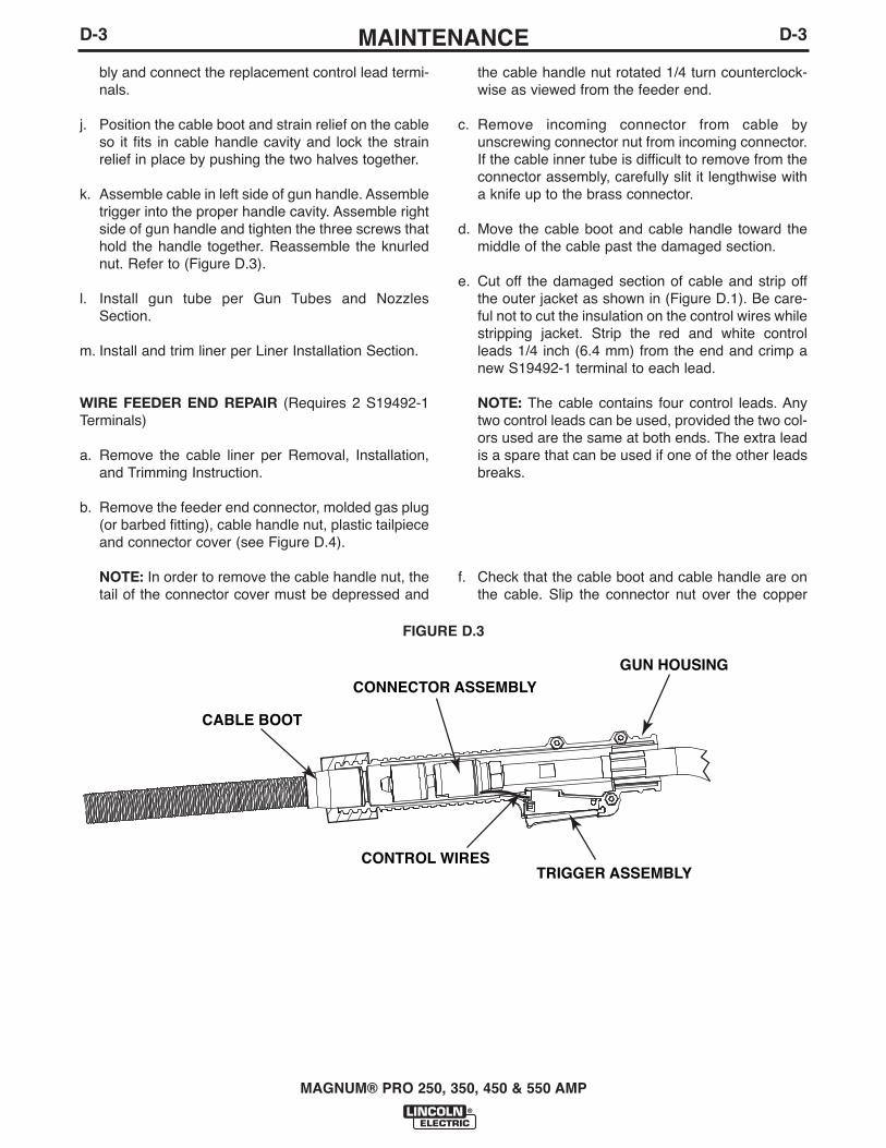
MAINTENANCEbly and connect the replacement control lead termi-nals.
j. Position the cable boot and strain relief on the cableso it fits in cable handle cavity and lock the strainrelief in place by pushing the two halves together.
k. Assemble cable in left side of gun handle. Assembletrigger into the proper handle cavity. Assemble rightside of gun handle and tighten the three screws thathold the handle together. Reassemble the knurlednut. Refer to (Figure D.3).
l. Install gun tube per Gun Tubes and NozzlesSection.
m. Install and trim liner per Liner Installation Section.
WIRE FEEDER END REPAIR (Requires 2 S19492-1Terminals)
a. Remove the cable liner per Removal, Installation,and Trimming Instruction.
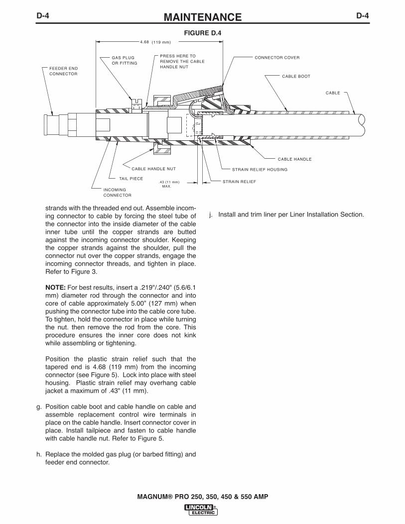
b. Remove the feeder end connector, molded gas plug(or barbed fitting), cable handle nut, plastic tailpieceand connector cover (see Figure D.4).
NOTE: In order to remove the cable handle nut, thetail of the connector cover must be depressed and
the cable handle nut rotated 1/4 turn counterclock-wise as viewed from the feeder end.
c. Remove incoming connector from cable byunscrewing connector nut from incoming connector.If the cable inner tube is difficult to remove from theconnector assembly, carefully slit it lengthwise witha knife up to the brass connector.
d. Move the cable boot and cable handle toward themiddle of the cable past the damaged section.
e. Cut off the damaged section of cable and strip offthe outer jacket as shown in (Figure D.1). Be care-ful not to cut the insulation on the control wires whilestripping jacket. Strip the red and white controlleads 1/4 inch (6.4 mm) from the end and crimp anew S19492-1 terminal to each lead.
NOTE: The cable contains four control leads. Anytwo control leads can be used, provided the two col-ors used are the same at both ends. The extra leadis a spare that can be used if one of the other leadsbreaks.
f. Check that the cable boot and cable handle are onthe cable. Slip the connector nut over the copper
MAGNUM® PRO 250, 350, 450 & 550 AMP
GUN HOUSING
TRIGGER ASSEMBLY
CABLE BOOT
CONTROL WIRES
CONNECTOR ASSEMBLY
FIGURE D.3
D-3D-3
MAINTENANCE
strands with the threaded end out. Assemble incom-ing connector to cable by forcing the steel tube ofthe connector into the inside diameter of the cableinner tube until the copper strands are buttedagainst the incoming connector shoulder. Keepingthe copper strands against the shoulder, pull theconnector nut over the copper strands, engage theincoming connector threads, and tighten in place.Refer to Figure 3.
NOTE: For best results, insert a .219"/.240" (5.6/6.1mm) diameter rod through the connector and intocore of cable approximately 5.00” (127 mm) whenpushing the connector tube into the cable core tube.To tighten, hold the connector in place while turningthe nut. then remove the rod from the core. Thisprocedure ensures the inner core does not kinkwhile assembling or tightening.
Position the plastic strain relief such that thetapered end is 4.68 (119 mm) from the incomingconnector (see Figure 5). Lock into place with steelhousing. Plastic strain relief may overhang cablejacket a maximum of .43" (11 mm).
g. Position cable boot and cable handle on cable andassemble replacement control wire terminals inplace on the cable handle. Insert connector cover inplace. Install tailpiece and fasten to cable handlewith cable handle nut. Refer to Figure 5.
h. Replace the molded gas plug (or barbed fitting) andfeeder end connector.
j. Install and trim liner per Liner Installation Section.
MAGNUM® PRO 250, 350, 450 & 550 AMP
4.68 (119 mm)
.43 (11 mm) MAX.
FEEDER ENDCONNECTOR
PRESS HERE TOREMOVE THE CABLEHANDLE NUT
GAS PLUGOR FITTING
CONNECTOR COVER
CABLE BOOT
CABLE
CABLE HANDLE
STRAIN RELIEF HOUSING
STRAIN RELIEF
INCOMINGCONNECTOR
TAIL PIECE
CABLE HANDLE NUT
FIGURE D.4
D-4D-4

TROUBLESHOOTING
MAGNUM® PRO 250, 350, 450 & 550 AMP
E-1E-1
If for any reason you do not understand the test procedures or are unable to perform the tests/repairs safely, contact your LocalLincoln Authorized Field Service Facility for technical troubleshooting assistance before you proceed.
CAUTION
This Troubleshooting Guide is provided to help youlocate and repair possible machine malfunctions.Simply follow the three-step procedure listed below.
Step 1. LOCATE PROBLEM (SYMPTOM).Look under the column labeled “PROBLEM (SYMP-TOMS)”. This column describes possible symptomsthat the machine may exhibit. Find the listing that bestdescribes the symptom that the machine is exhibiting.
Step 2. POSSIBLE CAUSE.The second column labeled “POSSIBLE CAUSE” liststhe obvious external possibilities that may contribute tothe machine symptom.
Step 3. RECOMMENDED COURSE OF ACTION
This column provides a course of action for thePossible Cause, generally it states to contact yourlocal Lincoln Authorized Field Service Facility.
If you do not understand or are unable to perform theRecommended Course of Action safely, contact yourlocal Lincoln Authorized Field Service Facility.
HOW TO USE TROUBLESHOOTING GUIDE
Service and Repair should only be performed by Lincoln Electric Factory Trained Personnel.Unauthorized repairs performed on this equipment may result in danger to the technician and machineoperator and will invalidate your factory warranty. For your safety and to avoid Electrical Shock, pleaseobserve all safety notes and precautions detailed throughout this manual.
__________________________________________________________________________
WARNING
E-2TROUBLESHOOTINGE-2
MAGNUM® PRO 250, 350, 450 & 550 AMP
Observe all Safety Guidelines detailed throughout this manual
If for any reason you do not understand the test procedures or are unable to perform the tests/repairs safely, contact your LocalLincoln Authorized Field Service Facility for technical troubleshooting assistance before you proceed.
CAUTION
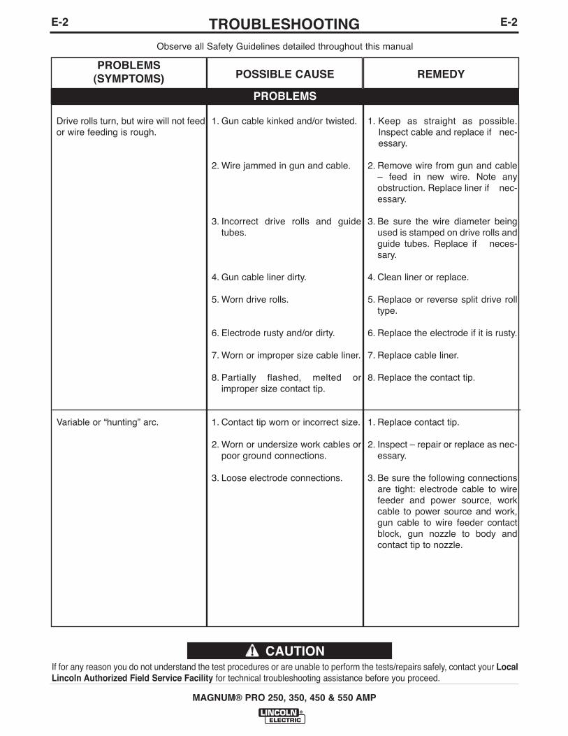
PROBLEMS
PROBLEMS(SYMPTOMS) POSSIBLE CAUSE REMEDY
Drive rolls turn, but wire will not feedor wire feeding is rough.
Variable or “hunting” arc.
1. Gun cable kinked and/or twisted.
2. Wire jammed in gun and cable.
3. Incorrect drive rolls and guidetubes.
4. Gun cable liner dirty.
5. Worn drive rolls.
6. Electrode rusty and/or dirty.
7. Worn or improper size cable liner.
8. Partially flashed, melted orimproper size contact tip.
1. Contact tip worn or incorrect size.
2. Worn or undersize work cables orpoor ground connections.
3. Loose electrode connections.
1. Keep as straight as possible.Inspect cable and replace if nec-essary.
2. Remove wire from gun and cable– feed in new wire. Note anyobstruction. Replace liner if nec-essary.
3. Be sure the wire diameter beingused is stamped on drive rolls andguide tubes. Replace if neces-sary.
4. Clean liner or replace.
5. Replace or reverse split drive rolltype.
6. Replace the electrode if it is rusty.
7. Replace cable liner.
8. Replace the contact tip.
1. Replace contact tip.
2. Inspect – repair or replace as nec-essary.
3. Be sure the following connectionsare tight: electrode cable to wirefeeder and power source, workcable to power source and work,gun cable to wire feeder contactblock, gun nozzle to body andcontact tip to nozzle.
TROUBLESHOOTING
MAGNUM® PRO 250, 350, 450 & 550 AMP
Observe all Safety Guidelines detailed throughout this manual
If for any reason you do not understand the test procedures or are unable to perform the tests/repairs safely, contact your LocalLincoln Authorized Field Service Facility for technical troubleshooting assistance before you proceed.
CAUTION
PROBLEMS
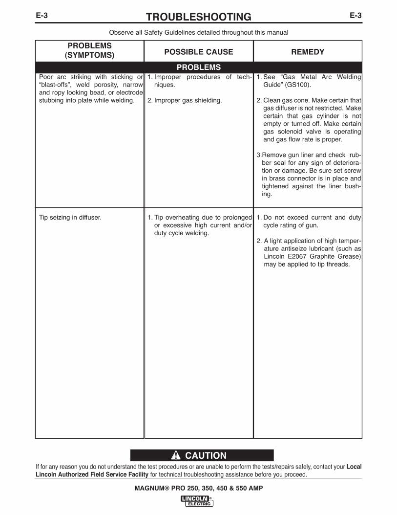
PROBLEMS(SYMPTOMS) POSSIBLE CAUSE REMEDY
Poor arc striking with sticking or“blast-offs”, weld porosity, narrowand ropy looking bead, or electrodestubbing into plate while welding.
Tip seizing in diffuser.
1. Improper procedures of tech-niques.
2. Improper gas shielding.
1. Tip overheating due to prolongedor excessive high current and/orduty cycle welding.
1. See “Gas Metal Arc WeldingGuide” (GS100).
2. Clean gas cone. Make certain thatgas diffuser is not restricted. Makecertain that gas cylinder is notempty or turned off. Make certaingas solenoid valve is operatingand gas flow rate is proper.
3.Remove gun liner and check rub-ber seal for any sign of deteriora-tion or damage. Be sure set screwin brass connector is in place andtightened against the liner bush-ing.
1. Do not exceed current and dutycycle rating of gun.
2. A light application of high temper-ature antiseize lubricant (such asLincoln E2067 Graphite Grease)may be applied to tip threads.
E-3E-3

NOTES
MAGNUM® PRO 250, 350, 450 AND 550
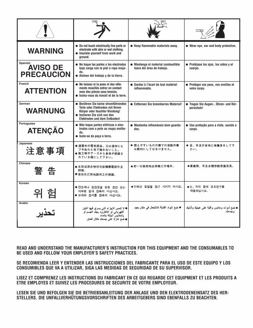
READ AND UNDERSTAND THE MANUFACTURER’S INSTRUCTION FOR THIS EQUIPMENT AND THE CONSUMABLES TOBE USED AND FOLLOW YOUR EMPLOYER’S SAFETY PRACTICES.
SE RECOMIENDA LEER Y ENTENDER LAS INSTRUCCIONES DEL FABRICANTE PARA EL USO DE ESTE EQUIPO Y LOSCONSUMIBLES QUE VA A UTILIZAR, SIGA LAS MEDIDAS DE SEGURIDAD DE SU SUPERVISOR.
LISEZ ET COMPRENEZ LES INSTRUCTIONS DU FABRICANT EN CE QUI REGARDE CET EQUIPMENT ET LES PRODUITS AETRE EMPLOYES ET SUIVEZ LES PROCEDURES DE SECURITE DE VOTRE EMPLOYEUR.
LESEN SIE UND BEFOLGEN SIE DIE BETRIEBSANLEITUNG DER ANLAGE UND DEN ELEKTRODENEINSATZ DES HER-STELLERS. DIE UNFALLVERHÜTUNGSVORSCHRIFTEN DES ARBEITGEBERS SIND EBENFALLS ZU BEACHTEN.
WARNING
AVISO DEPRECAUCION
ATTENTION
WARNUNG
ATENÇÃO
Spanish
French
German
Portuguese
Japanese
Chinese
Korean
Arabic
� Do not touch electrically live parts orelectrode with skin or wet clothing.
� Insulate yourself from work andground.
� No toque las partes o los electrodosbajo carga con la piel o ropa moja-da.
� Aislese del trabajo y de la tierra.
� Ne laissez ni la peau ni des vête-ments mouillés entrer en contactavec des pièces sous tension.
� Isolez-vous du travail et de la terre.
� Berühren Sie keine stromführendenTeile oder Elektroden mit IhremKörper oder feuchter Kleidung!
� Isolieren Sie sich von denElektroden und dem Erdboden!
� Não toque partes elétricas e elec-trodos com a pele ou roupa molha-da.
� Isole-se da peça e terra.
� Keep flammable materials away.
� Mantenga el material combustiblefuera del área de trabajo.
� Gardez à l’écart de tout matérielinflammable.
� Entfernen Sie brennbarres Material!
� Mantenha inflamáveis bem guarda-dos.
� Wear eye, ear and body protection.
� Protéjase los ojos, los oídos y elcuerpo.
� Protégez vos yeux, vos oreilles etvotre corps.
� Tragen Sie Augen-, Ohren- und Kör-perschutz!
� Use proteção para a vista, ouvido ecorpo.
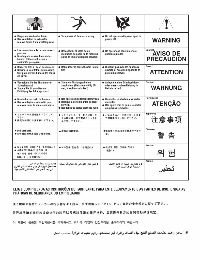
LEIA E COMPREENDA AS INSTRUÇÕES DO FABRICANTE PARA ESTE EQUIPAMENTO E AS PARTES DE USO, E SIGA ASPRÁTICAS DE SEGURANÇA DO EMPREGADOR.
WARNING
AVISO DEPRECAUCION
ATTENTION
WARNUNG
ATENÇÃO
Spanish
French
German
Portuguese
Japanese
Chinese
Korean
Arabic
� Keep your head out of fumes.� Use ventilation or exhaust to
remove fumes from breathing zone.
� Los humos fuera de la zona de res-piración.
� Mantenga la cabeza fuera de loshumos. Utilice ventilación oaspiración para gases.
� Gardez la tête à l’écart des fumées.� Utilisez un ventilateur ou un aspira-
teur pour ôter les fumées des zonesde travail.
� Vermeiden Sie das Einatmen vonSchweibrauch!
� Sorgen Sie für gute Be- undEntlüftung des Arbeitsplatzes!
� Mantenha seu rosto da fumaça.� Use ventilação e exhaustão para
remover fumo da zona respiratória.
� Turn power off before servicing.
� Desconectar el cable de ali-mentación de poder de la máquinaantes de iniciar cualquier servicio.
� Débranchez le courant avant l’entre-tien.
� Strom vor Wartungsarbeitenabschalten! (Netzstrom völlig öff-nen; Maschine anhalten!)
� Não opere com as tampas removidas.� Desligue a corrente antes de fazer
serviço.� Não toque as partes elétricas nuas.
� Do not operate with panel open orguards off.
� No operar con panel abierto oguardas quitadas.
� N’opérez pas avec les panneauxouverts ou avec les dispositifs deprotection enlevés.
� Anlage nie ohne Schutzgehäuseoder Innenschutzverkleidung inBetrieb setzen!
� Mantenha-se afastado das partesmoventes.
� Não opere com os paineis abertosou guardas removidas.

• Sales and Service through Subsidiaries and Distributors Worldwide •
Cleveland, Ohio 44117-1199 U.S.A. TEL: 216.481.8100 FAX: 216.486.1751 WEB SITE: www.lincolnelectric.com
• World's Leader in Welding and Cutting Products •


![Magnum PRO Robotic Guns Product Info...Magnum® PRO Robotic Gun | [ 3 ] EXPENDABLE PARTS Contact Tip for up to 550 A Magnum® PRO 550 A Expendables CONTACT TIPS 550 A Wire Diameter](https://img.dokumen.tips/doc/110x75/5fb66d5d864d7329f2314e8f/magnum-pro-robotic-guns-product-magnum-pro-robotic-gun-3-expendable.jpg)


![CEVH CEVH-1P-DECO Mounting instructions · External height Ht [mm] [mm] DECO RPK [mm] DECO RPK 400 450 494 400 450 470 450 500 544 450 500 520 500 550 594 500 550 570 550 600 644](https://img.dokumen.tips/doc/110x75/5f7023cb04a50125214b0344/cevh-cevh-1p-deco-mounting-instructions-external-height-ht-mm-mm-deco-rpk-mm.jpg)