Embed Size (px)
Citation preview
AL796MagnetoResistive FixPitch Sensor (2 mm)
DA
TA
SH
EE
T
AL796.DSE.10 Subject to technical changesSeptember 1212 2017
Data sheetPage 1 of 10
The AL796 is an AnisotropicMagnetoResistive (AMR) position sensor. The sensor contains two Wheatstone bridges shifted against each other. The out-put signals are proportional to sine and cosine of the coordinate to be mea-sured (see Fig. 2).
The MR strips of this FixPitch sensor geometrically match to a pole length of 2 mm (equal to a magnetic period of 4 mm). Additionally, the sensor layout incorporates PerfectWave technology, i. e. the position of each block of MR strips has a special arrangement to filter higher harmonics and to increase the signal quality. The resistances in this FixPitch sensor are distributed over sev - eral poles (2), thus the errors in the measurement scale are reduced without any signal delay. The amplitude is almost constant in a wide working range between sensor and magnetic scale.
The bond version of AL796 is available as bare die. For SMD processing, the sensor is available in a SIL6 or LGA package.
Features
– Based on the AnisotropicMagnetoResistive (AMR) effect
– Contains two Wheatstone bridges on Chip
– Sine and Cosine output
– Adapted to 2 mm poles
– PurePitch design (2 poles)
– PerfectWave technology
– Ambient temperature range from -40 °C to +125 °C
Advantages
– Contactless angle and position measurement
– Large air gap
– Excellent accuracy
– Minimized offset voltage
– Negligible hysteresis
Applications
Incremental or absolute encoder for linearor rotary movements in various industrialapplications, for example:
– Motor integrated encoder
– Motorfeedback system
Quick Reference Guide
Symbol Parameter Min. Typ. Max. Unit
P Pitch (magnetic pole length) - 2 - mm
VCC Supply voltage - 5.0 - V
Voff Offset voltage per VCC -2.0 - +2.0 mV/V
Vpeak Signal amplitude per VCC 9.0 11.0 13.0 mV/V
RB Bridge resistance 2.2 3.4 4.6 kΩ
1) Minimum order quantities apply.
Product Overview of AL796
Article description Package Delivery type
AL796ACA-AC Bare Die Wafer pack (192)
AL796ACA-AB Die on Wafer 1) Waferbox
AL796AKA-AC SIL6 Wafer pack (90)
AL796AMA-AE LGA6L Tape on reel (2500)
Absolute Maximum Ratings In accordance with the absolute maximum rating system (IEC60134).
Symbol Parameter Min. Max. Unit
VCC Supply voltage -9.0 +9.0 V
Tamb Ambient temperature -40 +125 °C
Tstg Storage temperature -65 +150 °C
Stresses beyond those listed under “Absolute maximum ratings” may cause permanent damage to the device. This is a stress rating only and functional operation of the device at these or any other conditions beyond those indicated in the operational sections of this specification is not implied. Exposure to absolute maximum ratingconditions for extended periods may affect device reliability.
RoHS-
Co
mpliant
www.sensi
tec.
com
AL796 MagnetoResistive FixPitch Sensor (2 mm)
Data sheetPage 2 of 10
DA
TA
SH
EE
T
AL796.DSE.10 Subject to technical changesSeptember 1212 2017
Accuracy Tamb = 25 °C; Hext = 25 kA/m; VCC = 5 V; unless otherwise specified.
Symbol Parameter Conditions Min. Typ. Max. Unit
ΔX Measurement error 8) - 5.0 7.0 µm
k Amplitude synchronism 9) - 0.1 1 % of Vpeak
General Data
Symbol Parameter Conditions Min. Typ. Max. Unit
P Pitch (magnetic pole length) See Fig. 1 - 2 - mm
d Distance 11) See Fig. 1 - 0.7 - mm
Tamb Ambient temperature -40 - +125 °C
Electrical Data Tamb = 25 °C; Hext = 25 kA/m; VCC = 5 V; unless otherwise specified.
Symbol Parameter Conditions Min. Typ. Max. Unit
VCC Supply voltage - 5.0 - V
Voff Offset voltage per VCC See Fig.2 -2.0 - +2.0 mV/V
TCVoff Temperature coefficient of Voff 2) Tamb = (-40...+125)°C -4.0 - +4.0 (µV/V)/K
Vpeak Signal amplitude per VCC 3) See Fig.2 9.0 11.0 13.0 mV/V
TCVpeak Temperature coefficient of Vpeak 4) Tamb = (-40...+125)°C -0.48 -0.42 -0.36 %/K
RB Bridge resistance 5) 2.2 3.4 4.6 kΩ
RS Sensor resistance 6) 1.1 1.7 2.3 kΩ
TCRB Temperature coefficient of RB 7) Tamb = (-40...+125)°C 0.24 0.28 0.32 %/K
2) TCVoff = Voff(T2) - Voff(T1)
with T1 = +25 °C; T2 = +125 °C.T2 - T1
3) Maximal output voltage without offset influences. Periodicity of Vpeak is sin(P) and cos(P).
4) TCVpeak = 100 ·Vpeak(T2) - Vpeak(T1)
with T1 = +25 °C; T2 = +125 °C. Vpeak(Tamb) · (T2 - T1)
5) Bridge resistance between +VO1 and -VO1, +VO2 and -VO2.
6) Sensor resistance between VCC and GND.
7) TCRB = 100 RB(T2) - RB(T1)
with T1 = +25 °C; T2 = +125 °C.RB(Tamb) · (T2 - T1)
8) ∆x = |xreal - xmeasured| without offset influences due to deviations from ideal sinusoidal characteristics (ascertained at an ideal magnetic scale).
9) k= 100 - 100 ·Vpeak1
.Vpeak2
Dynamic Data
Symbol Parameter Conditions Min. Typ. Max. Unit
f Frequency range 1 10) - - MHz
10) No significant amplitude loss in this frequency range.
Magnetic Data
Symbol Parameter Conditions Min. Typ. Max. Unit
Hext Magnetic field strength 1) 5.0 25.0 - kA/m
1) The stimulating magnetic field in the sensor plane to ensure minimum error specified in note 8.
11) See Fig. 3 for detailed information.
AL796 MagnetoResistive FixPitch Sensor (2 mm)
Data sheetPage 3 of 10
DA
TA
SH
EE
T
AL796.DSE.10 Subject to technical changesSeptember 1212 2017
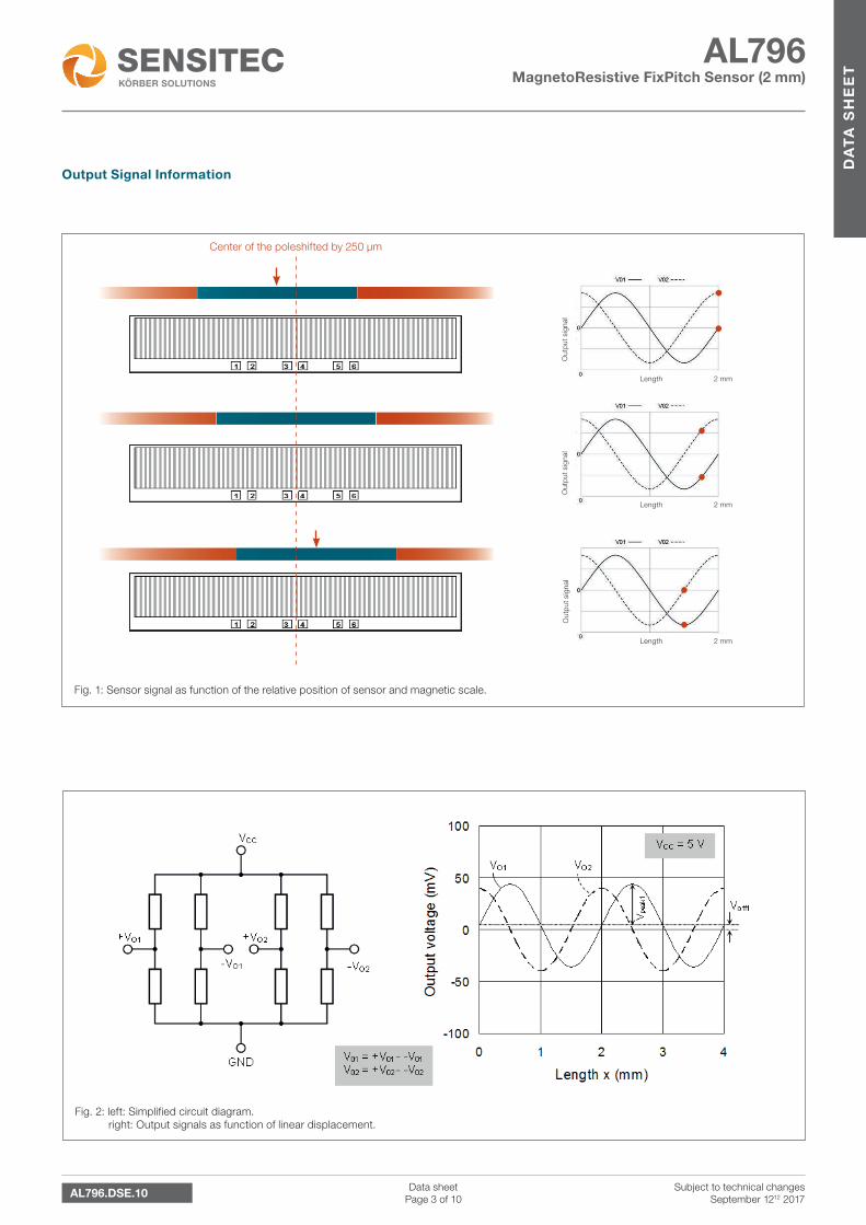
Fig. 2: left: Simplified circuit diagram. right: Output signals as function of linear displacement.
Output Signal Information
Center of the poleshifted by 250 µm
Out
put
sig
nal
Length
Length
Length
2 mm
2 mm
2 mm
Out
put
sig
nal
Out
put
sig
nal
Fig. 1: Sensor signal as function of the relative position of sensor and magnetic scale.
AL796 MagnetoResistive FixPitch Sensor (2 mm)
Data sheetPage 4 of 10
DA
TA
SH
EE
T
AL796.DSE.10 Subject to technical changesSeptember 1212 2017
Amplitude Error
Field Strength [kA/m]
35.0
30.0
25.0
20.0
15.0
10.0
5 .0
0.0
40.012,0
10,0
8,0
6,0
4,0
2,0
0,00 500 1000 1500 2000 2500 3000 3500 Distance [µm]
64 30 14 6 2.8 1.3 0.6 0.3
Amplitude [mV/V]
Error [µm]
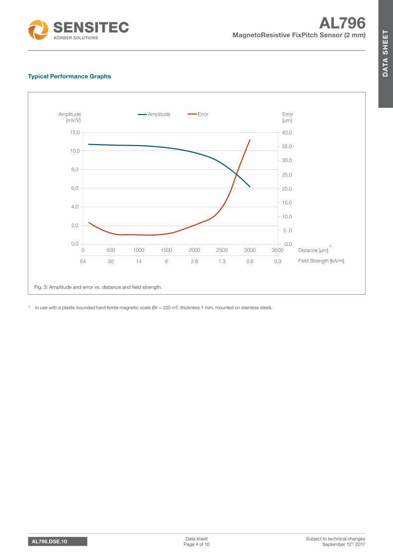
Fig. 3: Amplitude and error vs. distance and field strength.
Typical Performance Graphs
1) In use with a plastic bounded hard ferrite magnetic scale (Br = 220 mT, thickness 1 mm, mounted on stainless steel).
1)
AL796 MagnetoResistive FixPitch Sensor (2 mm)
Data sheetPage 5 of 10
DA
TA
SH
EE
T
AL796.DSE.10 Subject to technical changesSeptember 1212 2017
Mechanical Data
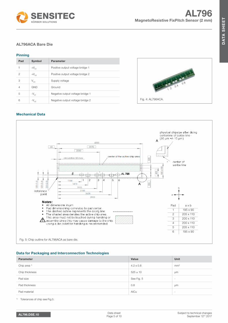
Fig. 5: Chip outline for AL796ACA as bare die.
Fig. 4: AL796ACA.
Pinning
Pad Symbol Parameter
1 +VO1 Positive output voltage bridge 1
2 +VO2 Positive output voltage bridge 2
3 VCC Supply voltage
4 GND Ground
5 -VO1 Negative output voltage bridge 1
6 -VO2 Negative output voltage bridge 2
AL796ACA Bare Die
Data for Packaging and Interconnection Technologies
Parameter Value Unit
Chip area 1) 4.2 x 0.8 mm2
Chip thickness 525 ± 10 µm
Pad size See Fig. 5 -
Pad thickness 0.8 µm
Pad material AlCu -
1) Tolerances of chip see Fig.5.
Pad a x b
1 195 x 90
2 205 x 110
3 200 x 110
4 200 x 110
5 205 x 110
6 195 x 90
1 2 3 4 5
6
a
b
AL796 MagnetoResistive FixPitch Sensor (2 mm)
Data sheetPage 6 of 10
DA
TA
SH
EE
T
AL796.DSE.10 Subject to technical changesSeptember 1212 2017
Dimensions
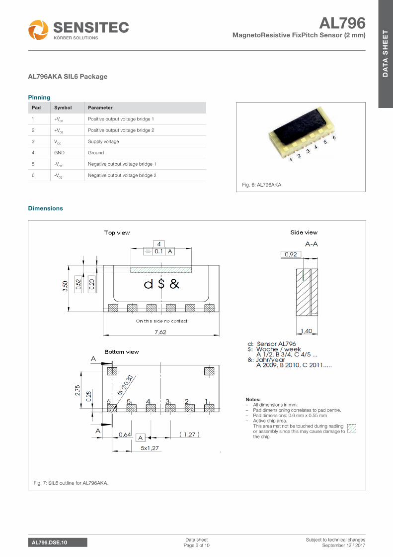
Fig. 7: SIL6 outline for AL796AKA.
Fig. 6: AL796AKA.
Pinning
Pad Symbol Parameter
1 +VO1 Positive output voltage bridge 1
2 +VO2 Positive output voltage bridge 2
3 VCC Supply voltage
4 GND Ground
5 -VO1 Negative output voltage bridge 1
6 -VO2 Negative output voltage bridge 2
AL796AKA SIL6 Package
Notes: – All dimensions in mm. – Pad dimensioning correlates to pad centre. – Pad dimensions: 0.6 mm x 0.55 mm – Active chip area.
This area mst not be touched during nadling or assembly since this may cause damage to the chip.
AL796 MagnetoResistive FixPitch Sensor (2 mm)
Data sheetPage 7 of 10
DA
TA
SH
EE
T
AL796.DSE.10 Subject to technical changesSeptember 1212 2017
Dimensions
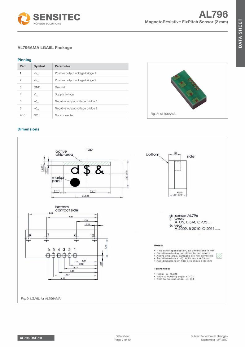
Fig. 9: LGA6L for AL796AMA.
Fig. 8: AL796AMA.
Pinning
Pad Symbol Parameter
1 +VO1 Positive output voltage bridge 1
2 +VO2 Positive output voltage bridge 2
3 GND Ground
4 VCC Supply voltage
5 -VO1 Negative output voltage bridge 1
6 -VO2 Negative output voltage bridge 2
7-10 NC Not connected
AL796AMA LGA6L Package
AL796 MagnetoResistive FixPitch Sensor (2 mm)
Data sheetPage 8 of 10
DA
TA
SH
EE
T
AL796.DSE.10 Subject to technical changesSeptember 1212 2017
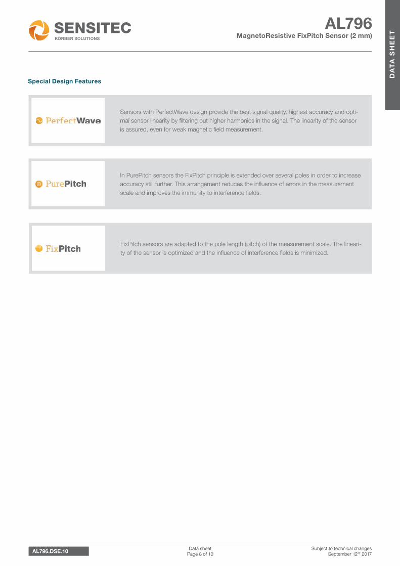
Sensors with PerfectWave design provide the best signal quality, highest accuracy and opti-mal sensor linearity by filtering out higher harmonics in the signal. The linearity of the sensor is assured, even for weak magnetic field measurement.
FixPitch sensors are adapted to the pole length (pitch) of the measurement scale. The lineari-ty of the sensor is optimized and the influence of interference fields is minimized.
In PurePitch sensors the FixPitch principle is extended over several poles in order to increase accuracy still further. This arrangement reduces the influence of errors in the measurement scale and improves the immunity to interference fields.
Special Design Features
AL796 MagnetoResistive FixPitch Sensor (2 mm)
Data sheetPage 9 of 10
DA
TA
SH
EE
T
AL796.DSE.10 Subject to technical changesSeptember 1212 2017
Product Status
Article Status
AL796ACA-AC The product is in series production.
AL796ACA-AB The product is in series production.
AL796AKA-AC The product is in series production.
AL796AMA-AE The product is in series production.
Note The status of the product may have changed since this data sheet was published. The latest information is available on the internet at www.sensitec.com.
General Information
Disclaimer
Sensitec GmbH reserves the right to make changes, without notice, in the products, including software, described or contained herein in order to improve design and/or performance. Information in this document is believed to be accurate and reliable. However, Sensitec GmbH does not give any representations or warranties, expressed or implied, as to the accuracy or completeness of such information and shall have no liability for the consequences of use of such information. Sensitec GmbH takes no responsibility for the content in this document if provided by an information source outside of Sensitec products.
In no event shall Sensitec GmbH be liable for any indirect, incidental, punitive, special or consequential damages (including but not limited to lost profits, lost savings, business interruption, costs related to the removal or replacement of any products or rework charges) irrespective the legal base the claims are based on, including but not limited to tort (including negligence), warranty, breach of contract, equity or any other legal theory.
Notwithstanding any damages that customer might incur for any reason whatsoever, Sensitec product aggregate and cumulative liability towards customer for the products described herein shall be limited in accordance with the General Terms and Conditions of Sale of Sensitec GmbH. Nothing in this document may be interpreted or construed as an offer to sell products that is open for acceptance or the grant, conveyance or implication of any license under any copyrights, patents or other industrial or intellectual property rights.
Unless otherwise agreed upon in an individual agreement Sensitec products sold are subject to the General Terms and Conditions of Sales as published at www.sensitec.com.
AL796 MagnetoResistive FixPitch Sensor (2 mm)
Data sheetPage 10 of 10
DA
TA
SH
EE
T
Sensitec GmbHGeorg-Ohm-Str. 11 · 35633 Lahnau · GermanyTel. +49 6441 9788-0 · Fax +49 6441 9788-17www.sensitec.com · [email protected]
Application Information
Applications that are described herein for any of these products are for illustrative purposes only. Sensitec GmbH makes no repre-sentation or warranty – whether expressed or implied – that such applications will be suitable for the specified use without further testing or modification.
Customers are responsible for the design and operation of their applications and products using Sensitec products, and Sensitec GmbH accepts no liability for any assistance with applications or customer product design. It is customer’s sole responsibility to determine whether the Sensitec product is suitable and fit for the customer’s applications and products planned, as well as for the planned application and use of customer’s third party customer(s). Customers should provide appropriate design and operating safeguards to minimize the risks associated with their applications and products.
Sensitec GmbH does not accept any liability related to any default, damage, costs or problem which is based on any weakness or default in the customer’s applications or products, or the application or use by customer’s third party customer(s). Customer is responsible for doing all necessary testing for the customer’s applications and products using Sensitec products in order to avoid a default of the applications and the products or of the application or use by customer’s third party customer(s).
Sensitec does not accept any liability in this respect.
Life Critical Applications
These products are not qualified for use in life support appliances, aeronautical applications or devices or systems where malfunc-tion of these products can reasonably be expected to result in personal injury.
Copyright © 2017 by Sensitec GmbH, Germany
All rights reserved. No part of this document may be copied or reproduced in any form or by any means without the prior written agreement of the copyright owner. The information in this document is subject to change without notice. Please observe that typical values cannot be guaranteed. Sensitec GmbH does not assume any liability for any consequence of its use.
General Information
AL796.DSE.10 Subject to technical changesSeptember 1212 2017
General Information