Embed Size (px)
Citation preview

Form 5 – Unit 2– Theme 6: Magnets and Motors Page 1
Magnetism
Magnetism is an effect that we cannot see, hear or touch.
It is caused by magnets.
A magnet is a body which attracts iron, combinations of
metals (known as alloys) or other materials which are
composed of iron or iron-like substances. Additionally, the magnet can "magnetize" other objects which in turn act like
magnets. Other iron objects will be attracted to the
magnetized object.
Types of magnets .
There are many different types of magnets, the most
common are Bar magnet, Flat magnet, horseshoe magnet
and ring magnets.
The Earth itself is a magnet and
contains a great deal of iron. On the other hand the Earth's moon is largely
made of aluminum, not iron. The
moon does not act like a magnet and
magnetic compasses do not work on
the moon.
Form 5 – Unit 2– Theme 6: Magnets and Motors Page 2
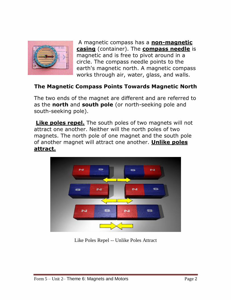
A magnetic compass has a non-magnetic
casing (container). The compass needle is
magnetic and is free to pivot around in a
circle. The compass needle points to the
earth's magnetic north. A magnetic compass
works through air, water, glass, and walls.
The Magnetic Compass Points Towards Magnetic North
The two ends of the magnet are different and are referred to
as the north and south pole (or north-seeking pole and
south-seeking pole).
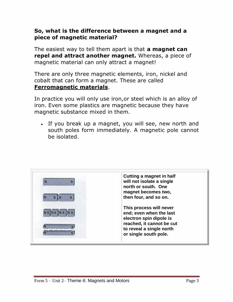
Like poles repel. The south poles of two magnets will not
attract one another. Neither will the north poles of two
magnets. The north pole of one magnet and the south pole
of another magnet will attract one another. Unlike poles
attract.
Like Poles Repel -- Unlike Poles Attract
Form 5 – Unit 2– Theme 6: Magnets and Motors Page 3
So, what is the difference between a magnet and a
piece of magnetic material?
The easiest way to tell them apart is that a magnet can
repel and attract another magnet. Whereas, a piece of
magnetic material can only attract a magnet!
There are only three magnetic elements, iron, nickel and
cobalt that can form a magnet. These are called
Ferromagnetic materials.
In practice you will only use iron,or steel which is an alloy of
iron. Even some plastics are magnetic because they have
magnetic substance mixed in them.
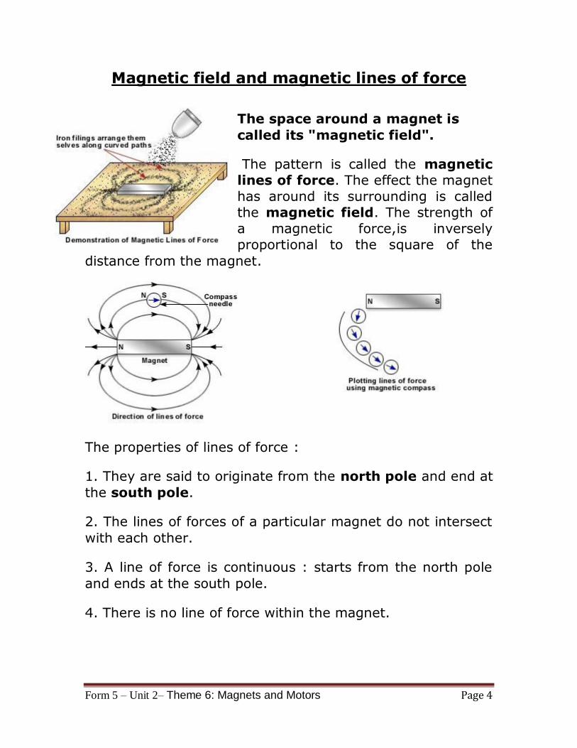
If you break up a magnet, you will see, new north and
south poles form immediately. A magnetic pole cannot
be isolated.
Cutting a magnet in half will not isolate a single north or south. One magnet becomes two, then four, and so on.
This process will never end; even when the last electron spin dipole is reached, it cannot be cut to reveal a single north or single south pole.
Form 5 – Unit 2– Theme 6: Magnets and Motors Page 4
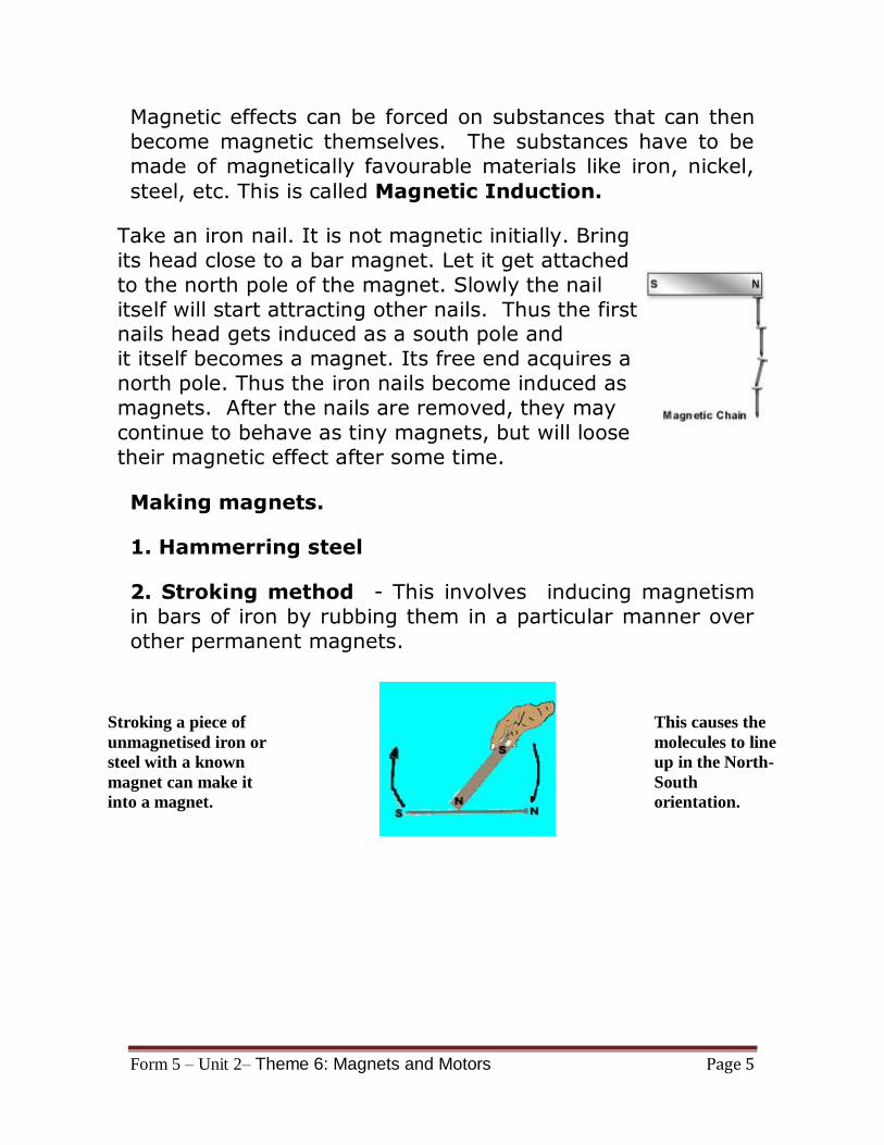
Magnetic field and magnetic lines of force
The space around a magnet is
called its "magnetic field".
The pattern is called the magnetic
lines of force. The effect the magnet
has around its surrounding is called
the magnetic field. The strength of
a magnetic force,is inversely
proportional to the square of the
distance from the magnet.
The properties of lines of force :
1. They are said to originate from the north pole and end at
the south pole.
2. The lines of forces of a particular magnet do not intersect
with each other.
3. A line of force is continuous : starts from the north pole
and ends at the south pole.
4. There is no line of force within the magnet.
Form 5 – Unit 2– Theme 6: Magnets and Motors Page 5
Magnetic effects can be forced on substances that can then
become magnetic themselves. The substances have to be
made of magnetically favourable materials like iron, nickel,
steel, etc. This is called Magnetic Induction.
Take an iron nail. It is not magnetic initially. Bring
its head close to a bar magnet. Let it get attached
to the north pole of the magnet. Slowly the nail
itself will start attracting other nails. Thus the first nails head gets induced as a south pole and
it itself becomes a magnet. Its free end acquires a
north pole. Thus the iron nails become induced as
magnets. After the nails are removed, they may
continue to behave as tiny magnets, but will loose
their magnetic effect after some time.
Making magnets.
1. Hammerring steel
2. Stroking method - This involves inducing magnetism
in bars of iron by rubbing them in a particular manner over
other permanent magnets.
Stroking a piece of
unmagnetised iron or
steel with a known
magnet can make it
into a magnet.
This causes the
molecules to line
up in the North-
South
orientation.
Form 5 – Unit 2– Theme 6: Magnets and Motors Page 6
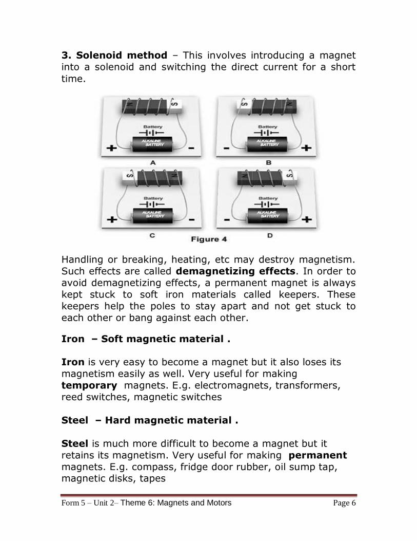
3. Solenoid method – This involves introducing a magnet
into a solenoid and switching the direct current for a short
time.
Handling or breaking, heating, etc may destroy magnetism.
Such effects are called demagnetizing effects. In order to
avoid demagnetizing effects, a permanent magnet is always
kept stuck to soft iron materials called keepers. These
keepers help the poles to stay apart and not get stuck to
each other or bang against each other.
Iron – Soft magnetic material .
Iron is very easy to become a magnet but it also loses its
magnetism easily as well. Very useful for making
temporary magnets. E.g. electromagnets, transformers,
reed switches, magnetic switches
Steel – Hard magnetic material .
Steel is much more difficult to become a magnet but it
retains its magnetism. Very useful for making permanent
magnets. E.g. compass, fridge door rubber, oil sump tap, magnetic disks, tapes
Form 5 – Unit 2– Theme 6: Magnets and Motors Page 7
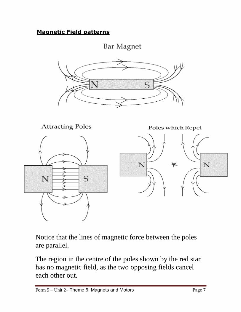
Magnetic Field patterns
Notice that the lines of magnetic force between the poles
are parallel.
The region in the centre of the poles shown by the red star
has no magnetic field, as the two opposing fields cancel
each other out.
Form 5 – Unit 2– Theme 6: Magnets and Motors Page 8
Electro Magnetism
An electric current produces a magnetic field. The Danish
physicist H. C. Oersted first discovered this relationship.
This magnetic field strength could be increased when the
electrical wire was wound into a coil. Winding the wire
around a soft-iron core can increase magnetic strength hundreds or thousands of times. Such a device is known as
an electromagnet.
Advantages of an electromagnet over a natural magnet include strength and the ability to control the current
and direction.
Examples :
1. Salvage yard cranes.
2. Lifting magnets are also used to load machine parts,
steel rails and scrap iron or steel.
3. Burglar alarms use magnets.
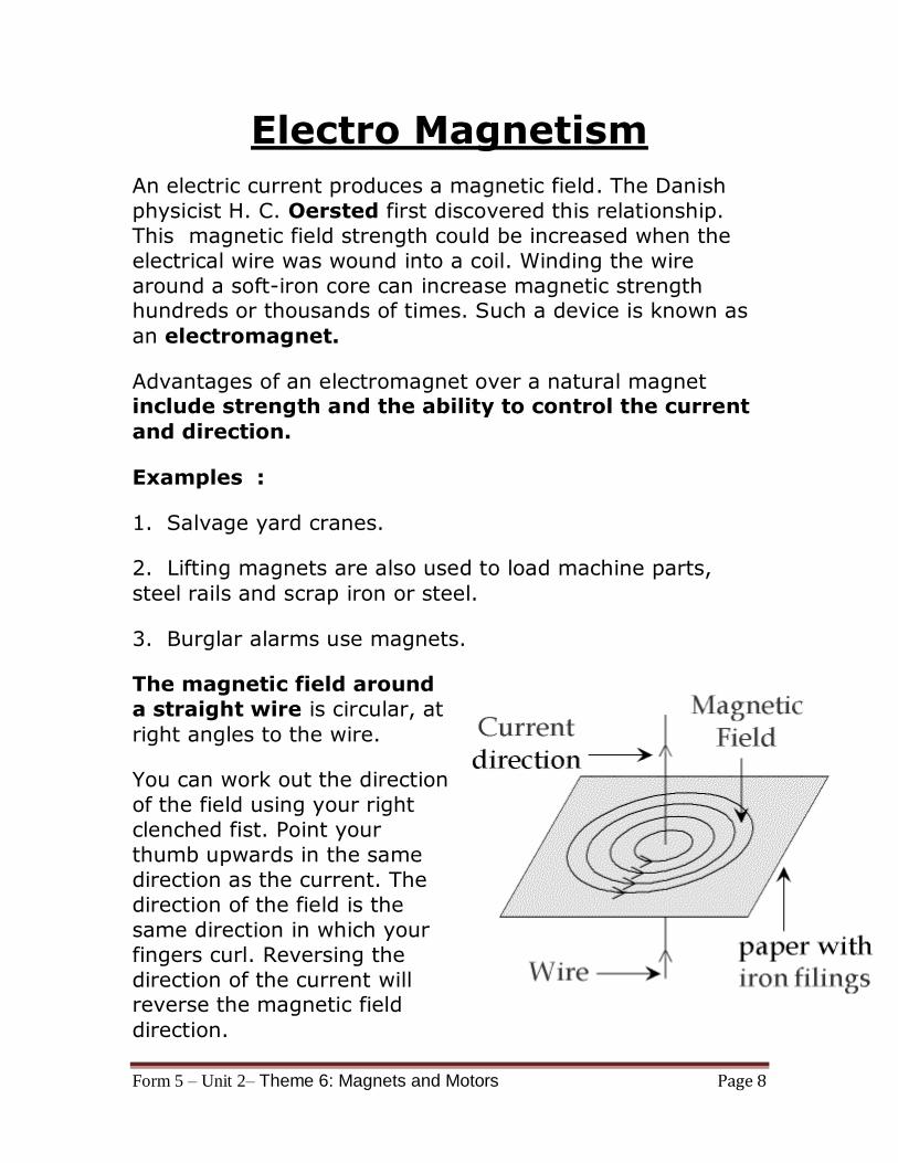
The magnetic field around
a straight wire is circular, at
right angles to the wire.
You can work out the direction
of the field using your right
clenched fist. Point your
thumb upwards in the same
direction as the current. The
direction of the field is the
same direction in which your
fingers curl. Reversing the
direction of the current will reverse the magnetic field
direction.
Form 5 – Unit 2– Theme 6: Magnets and Motors Page 9
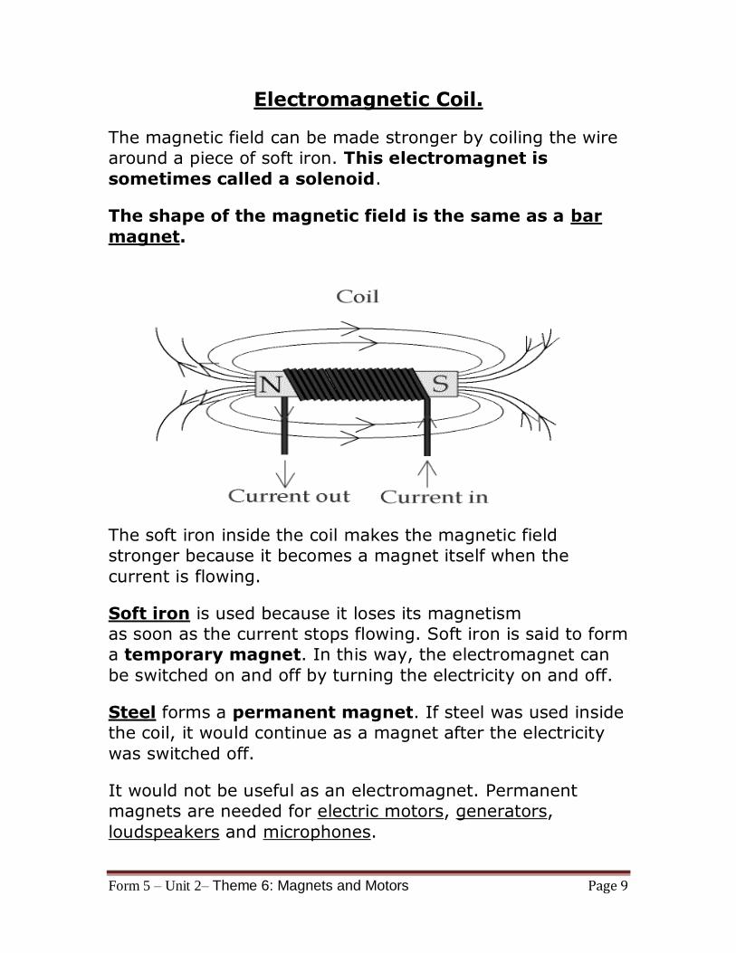
Electromagnetic Coil.
The magnetic field can be made stronger by coiling the wire
around a piece of soft iron. This electromagnet is
sometimes called a solenoid.
The shape of the magnetic field is the same as a bar
magnet.
The soft iron inside the coil makes the magnetic field
stronger because it becomes a magnet itself when the
current is flowing.
Soft iron is used because it loses its magnetism
as soon as the current stops flowing. Soft iron is said to form
a temporary magnet. In this way, the electromagnet can
be switched on and off by turning the electricity on and off.
Steel forms a permanent magnet. If steel was used inside
the coil, it would continue as a magnet after the electricity
was switched off.
It would not be useful as an electromagnet. Permanent
magnets are needed for electric motors, generators,
loudspeakers and microphones.
Form 5 – Unit 2– Theme 6: Magnets and Motors Page 10
The strength of the magnetic field around the coil can
be increased by
1. Using a soft iron core (core means middle bit).
2. Using more turns of wire on the coil.
3. Using a bigger current.
Reversing the direction of the current will reverse the
magnetic field direction.
An electromagnet is used in the electric bell, relay,
circuit breaker, loudspeaker
and microphone.
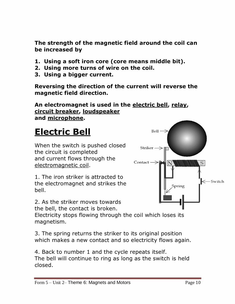
Electric Bell
When the switch is pushed closed
the circuit is completed
and current flows through the
electromagnetic coil.
1. The iron striker is attracted to
the electromagnet and strikes the
bell.
2. As the striker moves towards
the bell, the contact is broken.
Electricity stops flowing through the coil which loses its
magnetism.
3. The spring returns the striker to its original position
which makes a new contact and so electricity flows again.
4. Back to number 1 and the cycle repeats itself.
The bell will continue to ring as long as the switch is held
closed.

Form 5 – Unit 2– Theme 6: Magnets and Motors Page 11
Relay Switch
The relay consists of two circuits.
Circuit 1 is a simple
electromagnet which requires
only a small current. When the
switch is closed, current flows
and the iron rocker arm is attracted to the electromagnet.
The arm rotates about the central
pivot and pushes the contacts
together. Circuit 2 is now
switched on.
Circuit 2 may have a large current flowing through it, to
operate a powerful motor or very bright lights.
When the switch is opened the electromagnet releases the
rocker arm and the spring moves the contacts apart.
Circuit 2 is now switched off.
The advantage of using a relay is that a small current
(circuit 1) can be used to switch on and off a circuit
with a large current (circuit 2).
This is useful for two reasons:
(i) circuit 1 may contain a component such as an LDR,
which only uses small currents, (ii) only the high current circuit needs to be made from thick
wire.
A relay is used to operate the starter motor in cars
and the heating circuit in diesel engines.
Form 5 – Unit 2– Theme 6: Magnets and Motors Page 12
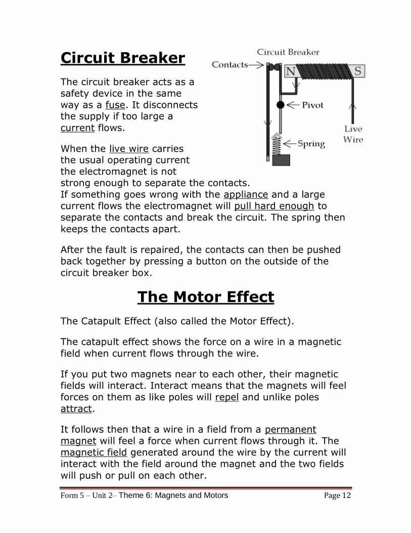
Circuit Breaker
The circuit breaker acts as a
safety device in the same
way as a fuse. It disconnects the supply if too large a
current flows.
When the live wire carries the usual operating current
the electromagnet is not
strong enough to separate the contacts.
If something goes wrong with the appliance and a large
current flows the electromagnet will pull hard enough to
separate the contacts and break the circuit. The spring then
keeps the contacts apart.
After the fault is repaired, the contacts can then be pushed
back together by pressing a button on the outside of the
circuit breaker box.
The Motor Effect
The Catapult Effect (also called the Motor Effect).
The catapult effect shows the force on a wire in a magnetic
field when current flows through the wire.
If you put two magnets near to each other, their magnetic
fields will interact. Interact means that the magnets will feel
forces on them as like poles will repel and unlike poles
attract.
It follows then that a wire in a field from a permanent
magnet will feel a force when current flows through it. The
magnetic field generated around the wire by the current will
interact with the field around the magnet and the two fields
will push or pull on each other.
Form 5 – Unit 2– Theme 6: Magnets and Motors Page 13
The magnetic field around a straight wire is circular.
The magnetic field between two attracting poles is straight.
When the two interact, the wire is pushed away from the
field between the attracting poles at right angles (90°) both
to the straight field lines and to the direction of current flow.
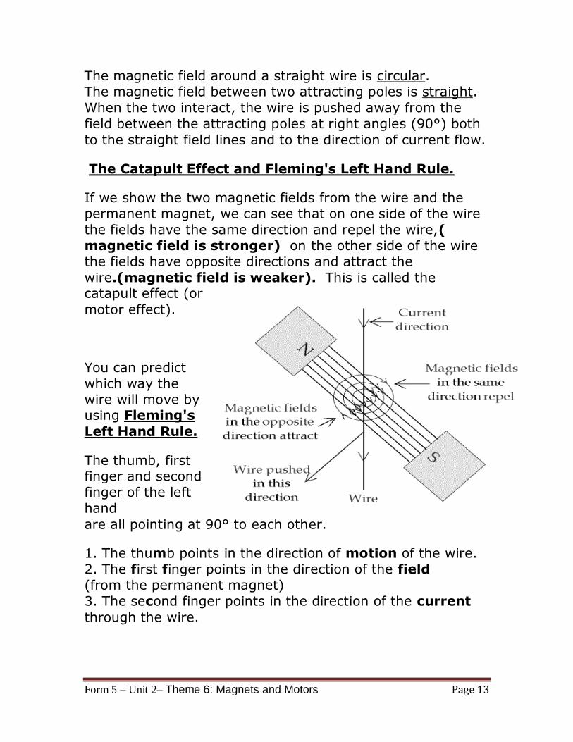
The Catapult Effect and Fleming's Left Hand Rule.
If we show the two magnetic fields from the wire and the
permanent magnet, we can see that on one side of the wire
the fields have the same direction and repel the wire,(
magnetic field is stronger) on the other side of the wire
the fields have opposite directions and attract the
wire.(magnetic field is weaker). This is called the catapult effect (or
motor effect).
You can predict
which way the
wire will move by using Fleming's
Left Hand Rule.
The thumb, first finger and second
finger of the left
hand
are all pointing at 90° to each other.
1. The thumb points in the direction of motion of the wire.
2. The first finger points in the direction of the field
(from the permanent magnet)
3. The second finger points in the direction of the current
through the wire.
Form 5 – Unit 2– Theme 6: Magnets and Motors Page 14
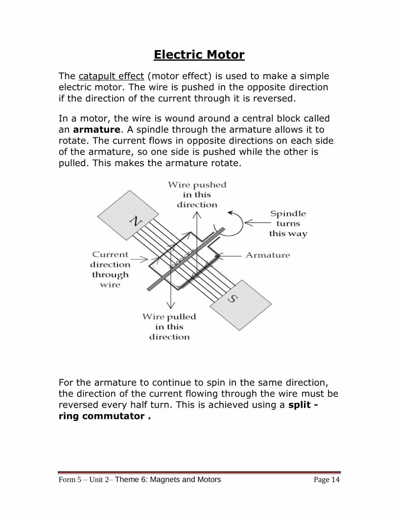
Electric Motor
The catapult effect (motor effect) is used to make a simple
electric motor. The wire is pushed in the opposite direction
if the direction of the current through it is reversed.
In a motor, the wire is wound around a central block called
an armature. A spindle through the armature allows it to
rotate. The current flows in opposite directions on each side
of the armature, so one side is pushed while the other is
pulled. This makes the armature rotate.
For the armature to continue to spin in the same direction,
the direction of the current flowing through the wire must be
reversed every half turn. This is achieved using a split -
ring commutator .
Form 5 – Unit 2– Theme 6: Magnets and Motors Page 15
A split - ring commutator (sometimes just called a
commutator) is a simple and clever device for reversing the
current direction through an armature every half turn.
The commutator is made from two round pieces of copper,
one on each side of the spindle.
A piece of carbon (graphite) is lightly pushed against the
copper to conduct the electricity to the armature. (brushes)
The carbon brushes against the copper when the
commutator spins.
As the motor rotates, first one piece of copper, then the next
connects with the brush every half turn. The wire on the left
side of the armature always has current flowing in the same
direction, and so the armature will keep turning in the same
direction .
Induced Current
Just as a current flowing through a wire will produce a magnetic field, so a wire moving through a magnetic field
will have a current flowing through it. This is called induced
current.
The same effect occurs in a stationary wire in a changing magnetic field. It does not matter if the wire is moved near
to a magnet or a magnet is moved near a wire, so long as
one is moving in relation to the other.
A stationary wire in a magnetic field which is not changing
will not have a current induced in it.
Induced current is used in electricity generation and
transformers.
Form 5 – Unit 2– Theme 6: Magnets and Motors Page 16
Faraday's Law
The voltage induced in a conductor is directly
proportional to the rate at which the magnetic field
lines are cut by the conductor.
The change could be produced by changing the magnetic
field strength, moving a magnet toward or away from the
coil, moving the coil into or out of the magnetic field,
rotating the coil relative to the magnet, etc.
Induced Current in a Coil
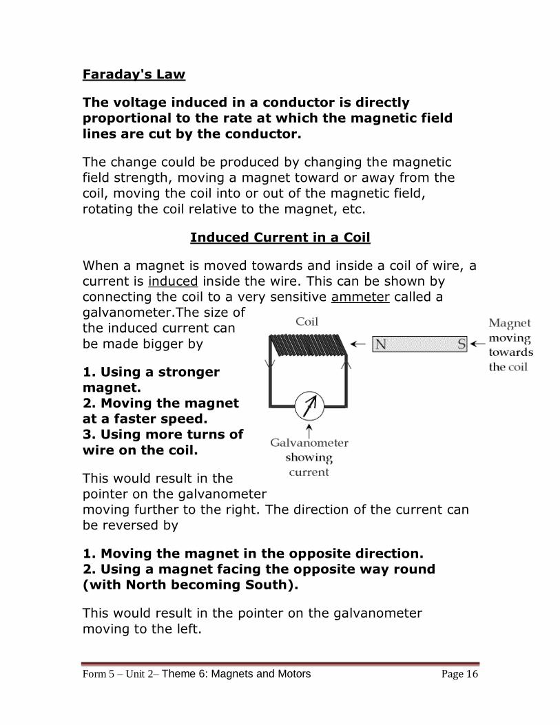
When a magnet is moved towards and inside a coil of wire, a
current is induced inside the wire. This can be shown by
connecting the coil to a very sensitive ammeter called a
galvanometer.The size of
the induced current can
be made bigger by
1. Using a stronger
magnet.
2. Moving the magnet
at a faster speed.
3. Using more turns of
wire on the coil.
This would result in the
pointer on the galvanometer
moving further to the right. The direction of the current can
be reversed by
1. Moving the magnet in the opposite direction.
2. Using a magnet facing the opposite way round
(with North becoming South).
This would result in the pointer on the galvanometer
moving to the left.
Form 5 – Unit 2– Theme 6: Magnets and Motors Page 17
Lenz’s law: The direction of the induced current always
opposes the change producing it.
Induced Current in a Generator.
The effect of inducing a current in a coil by moving a magnet
inside it is used for the large scale generation of electricity in
power stations.
There are two types of generator or dynamo. Both turn
rotational energy into electrical energy.
1. One type involves rotating a coil inside a magnet.
2. The other type involves rotating a magnet inside a coil
(like a dynamo found on a bicycle).
Both types produce alternating current.
It is possible to make a generator without a permanent
magnet. The generator used on cars (called an alternator)
uses an inner set of coils to make an electromagnet
which turns the Generator.
A simple generator is similar to an electric motor. With a
motor, we put electrical energy in and get rotational energy out, with a generator we put rotational energy in and get
electrical energy out.
line) showing that a higher voltage is induced in the coil around the armature. This happens because the coil is
moving through the field from the permanent magnet more
quickly.
Form 5 – Unit 2– Theme 6: Magnets and Motors Page 18
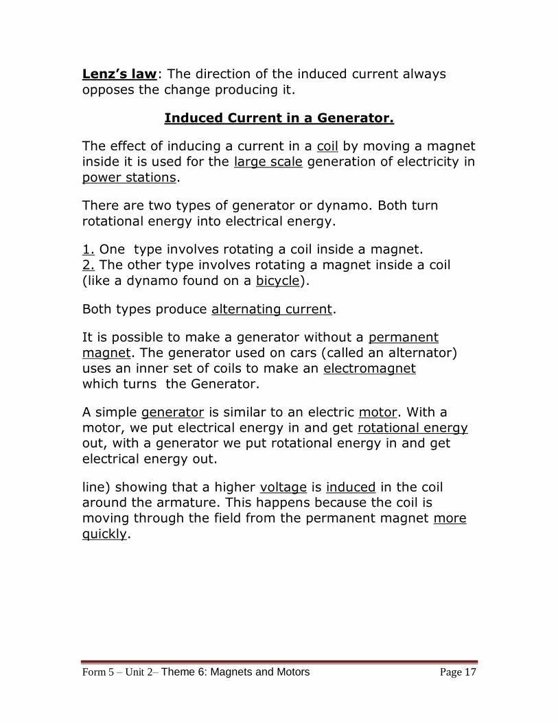
Bicycle Dynamo.
A small generator is sometimes
fitted to a bicycle to provide
electricity for the lights at night. A permanent magnet is rotated in the
middle of coils of wire. This has the
advantage that slip rings are not
needed because the outer coils do
not move.
The top of the dynamo is touched
against the rim of the tyre
which rotates when the bicycle is moving.
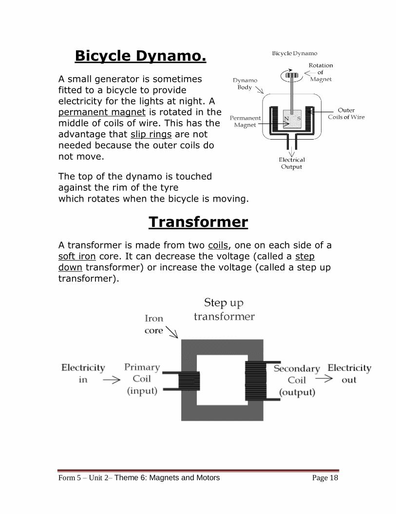
Transformer
A transformer is made from two coils, one on each side of a
soft iron core. It can decrease the voltage (called a step
down transformer) or increase the voltage (called a step up
transformer).
Form 5 – Unit 2– Theme 6: Magnets and Motors Page 19
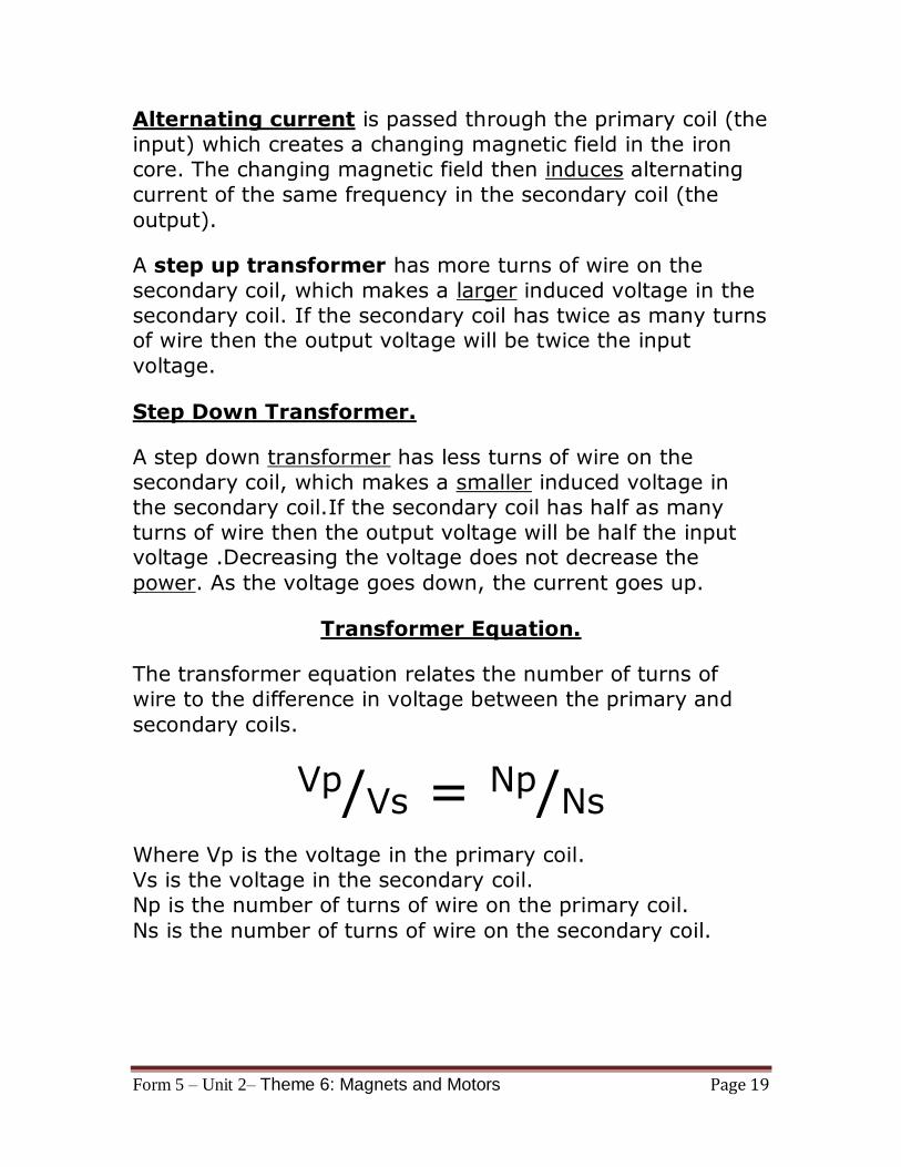
Alternating current is passed through the primary coil (the
input) which creates a changing magnetic field in the iron
core. The changing magnetic field then induces alternating
current of the same frequency in the secondary coil (the
output).
A step up transformer has more turns of wire on the
secondary coil, which makes a larger induced voltage in the
secondary coil. If the secondary coil has twice as many turns of wire then the output voltage will be twice the input
voltage.
Step Down Transformer.
A step down transformer has less turns of wire on the
secondary coil, which makes a smaller induced voltage in
the secondary coil.If the secondary coil has half as many
turns of wire then the output voltage will be half the input voltage .Decreasing the voltage does not decrease the
power. As the voltage goes down, the current goes up.
Transformer Equation.
The transformer equation relates the number of turns of
wire to the difference in voltage between the primary and
secondary coils.
Vp/Vs = Np/Ns Where Vp is the voltage in the primary coil.
Vs is the voltage in the secondary coil.
Np is the number of turns of wire on the primary coil.
Ns is the number of turns of wire on the secondary coil.
Form 5 – Unit 2– Theme 6: Magnets and Motors Page 20
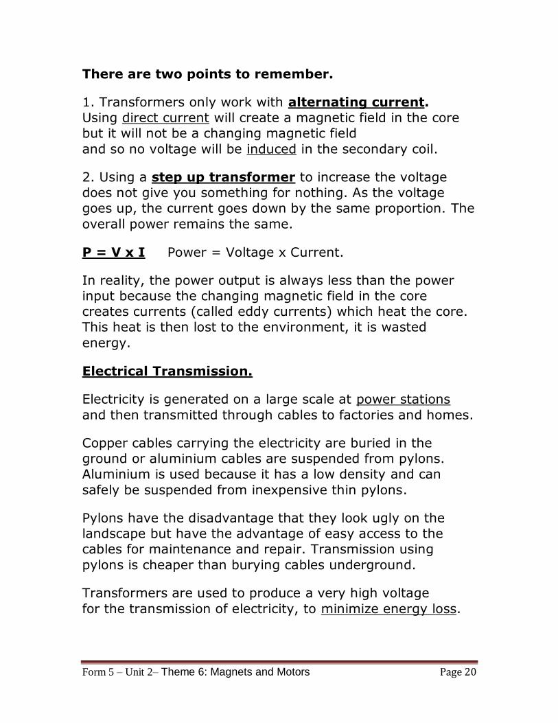
There are two points to remember.
1. Transformers only work with alternating current.
Using direct current will create a magnetic field in the core
but it will not be a changing magnetic field
and so no voltage will be induced in the secondary coil.
2. Using a step up transformer to increase the voltage
does not give you something for nothing. As the voltage
goes up, the current goes down by the same proportion. The
overall power remains the same.
P = V x I Power = Voltage x Current.
In reality, the power output is always less than the power
input because the changing magnetic field in the core
creates currents (called eddy currents) which heat the core.
This heat is then lost to the environment, it is wasted
energy.
Electrical Transmission.
Electricity is generated on a large scale at power stations
and then transmitted through cables to factories and homes.
Copper cables carrying the electricity are buried in the
ground or aluminium cables are suspended from pylons.
Aluminium is used because it has a low density and can
safely be suspended from inexpensive thin pylons.
Pylons have the disadvantage that they look ugly on the
landscape but have the advantage of easy access to the
cables for maintenance and repair. Transmission using
pylons is cheaper than burying cables underground.
Transformers are used to produce a very high voltage
for the transmission of electricity, to minimize energy loss.
Form 5 – Unit 2– Theme 6: Magnets and Motors Page 21
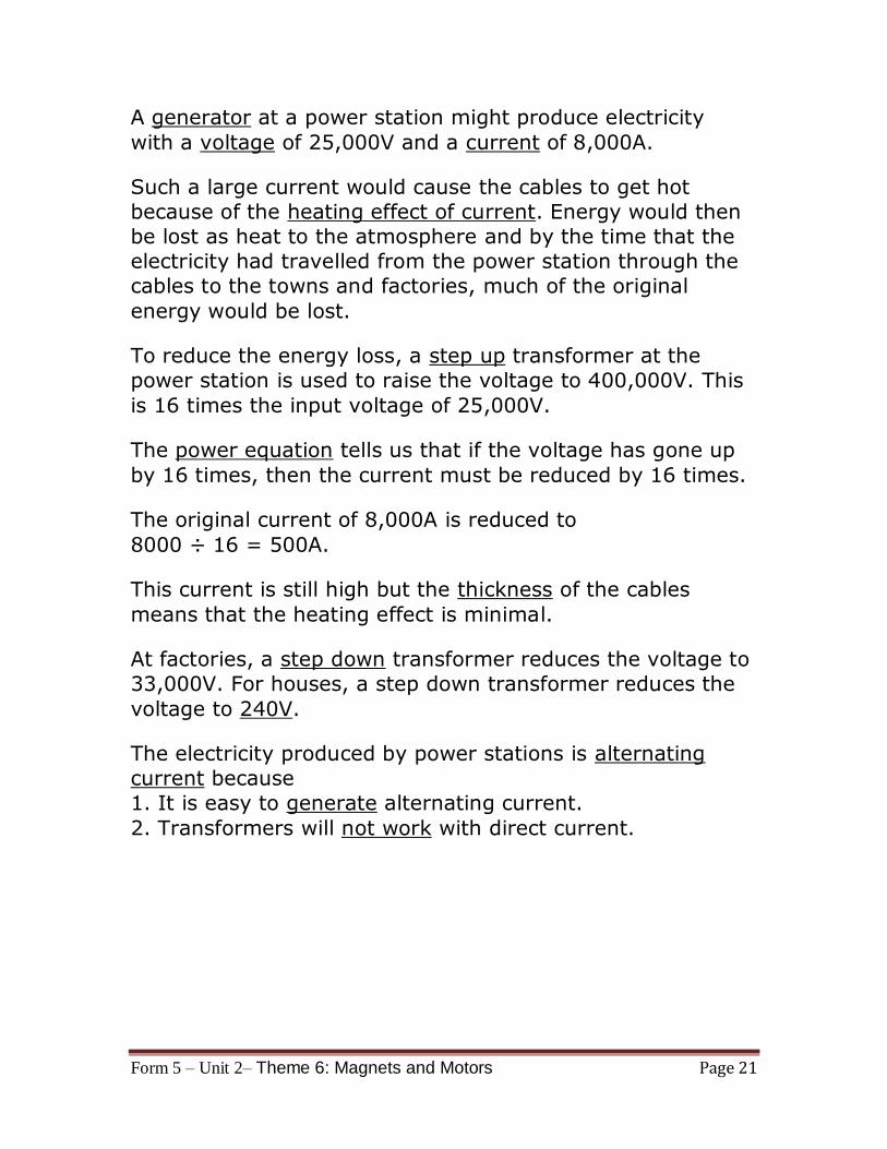
A generator at a power station might produce electricity
with a voltage of 25,000V and a current of 8,000A.
Such a large current would cause the cables to get hot
because of the heating effect of current. Energy would then
be lost as heat to the atmosphere and by the time that the
electricity had travelled from the power station through the
cables to the towns and factories, much of the original
energy would be lost.
To reduce the energy loss, a step up transformer at the
power station is used to raise the voltage to 400,000V. This
is 16 times the input voltage of 25,000V.
The power equation tells us that if the voltage has gone up
by 16 times, then the current must be reduced by 16 times.
The original current of 8,000A is reduced to
8000 ÷ 16 = 500A.
This current is still high but the thickness of the cables
means that the heating effect is minimal.
At factories, a step down transformer reduces the voltage to
33,000V. For houses, a step down transformer reduces the
voltage to 240V.
The electricity produced by power stations is alternating
current because
1. It is easy to generate alternating current.
2. Transformers will not work with direct current.

![1 L 27 Electricity & Magnetism [5] Magnets –permanent magnets –Electromagnets –The Earth’s magnetic field magnetic forces applications Magnetism](https://img.dokumen.tips/doc/110x75/56649d9c5503460f94a85bd1/1-l-27-electricity-magnetism-5-magnets-permanent-magnets-electromagnets.jpg)


![1 L 28 Electricity and Magnetism [5] magnetism magnetic forces applications Why are magnets magnets?](https://img.dokumen.tips/doc/110x75/56649f485503460f94c6a785/1-l-28-electricity-and-magnetism-5-magnetism-magnetic-forces-applications.jpg)