Embed Size (px)
Citation preview

D.Whitehall
1
MAGNETISM Magnet A magnet is any material that is able to attract iron or steel. Materials that are
attracted to magnets are called ferromagnetic. (e.g. iron, steel, cobalt)
When a piece of material is brought close to or stroked by a magnet, the material itself
becomes magnetic.
If a material looses its magnetism when the magnet is removed then the magnetism is
said to be temporary. Hence if the material keeps the magnetism when the magnet is
removed, the magnetism is said to be permanent.
Soft iron can be easily magnetised but it does not retain its magnetism (temporary
magnet). However, hard steel is more difficult to magnetised but retain their
magnetism (permanent magnet).
All magnets have two (2) poles: a North Pole and South Pole. Experiments also show
that:
1. unlike poles attract and like poles repel each other.
2. forces of attraction decreases as the poles get further apart.

D.Whitehall
2
Magnetic Fields and Forces The magnetic field around the magnet is the region in which forces act on other
magnetic materials by inducing on it.
Direction of a Magnetic Field
The direction of a magnetic field is the force produces on a magnetic north pole.
(North South)
The diagrams below show different arrangements of magnetic flux patterns.

D.Whitehall
3
Electromagnetism Oersted’s Discovery
In 1819, Hans Christian Oersted discovered that where an electric current flowed
through a wire, it was able to deflect a compass needle. His experiment demonstrated
that a magnetic field existed everywhere around the wire and its direction depended
on the direction of the current and the position around the wire. We can use either
‘Maxwell’s Corkscrew Rule’ or ‘Right Hand Grip Rule’ to predict the direction of
the field around the wire.
Maxwell’s Corkscrew Rule (Right-hand screw rule)
If a right-handed screw is turned so that it moves in the same direction as the
convectional current, then the direction of the magnetic field is due to the direction of
the current.

D.Whitehall
4
Right-Hand Grip Rule
If a wire carrying a current is gripped with the right hand and the thumb is pointing
along the wire in the direction of the current; then the fingers point in the direction of
the magnetic field around the wire.
(N.B. Circular magnetic fields are formed when currents flow through a straight
conductor)

D.Whitehall
5
Magnetic Field in Flat Circular Coil
Solenoid (Multiple Loops) A solenoid is large number of circular insulated coil wounds close together. The field
due to the solenoids is the vector sum of the fields all the coils. The field produce is
exactly like the bar magnet.

D.Whitehall
6
Electromagnets
This is made up of a coil of wire wound on a soft iron core (solenoid on a soft iron
core). When the current is switched, on the iron core becomes magnetised and it
easily loses its magnetism when the current is removed. Electromagnets are a very
strong magnet and can be used to lift heavy objects in construction.
Examples of Electromagnets
Electric Bell

D.Whitehall
7
The electric bell consists of a solenoid and a soft iron core (electromagnet). One end
is connected to the battery while the other end is connected to a steel strip (spring)
that supports the soft iron armature. The spring with the armature is pressed against a
contact screw that has a wire that connects back to the battery. When the switch is
pressed, the current flows through the circuit and the soft iron core becomes
magnetised. The armature attracts to the soft iron core which results in the hammer
striking the gong once. Simultaneously, the spring moves away from the contact
screw, breaking the circuit and the stopping the current from flowing. The
electromagnet is no longer magnetised and it releases the armature, which returns to
its original position. The spring is once again touching the contact screw, the circuit is
reformed and hence the current flows again and the process is repeated.
Magnetic Relay
The magnetic relay is a switching device, which uses an electromagnet. It has two or
more completely separate circuits. (Input circuit at terminals P and Q. Output circuits
at R and S). When the current flows in the coil from the input circuit the soft iron core
becomes magnetised and attracts one end of the armature. The armature rocks at its
pivot and closes the contact at C in the output circuit.
Vehicle Starting Motor Circuit
The starter motor has a difficult job of turning a stiff engine. Hence a large current is
required to do this. As a result the starter motor is placed on a separate circuit and a
relay is used to close the contacts in the starter motor circuit

D.Whitehall
8
When the ignition is turned on, a small current pass through the solenoid. The
armature inside the solenoid pushes against the spring and closes the contacts of the
starter motor circuit allowing a very large circuit to pass through the starter motor.
Advantages of the Magnetic Relay
1. One circuit can be used to control another circuit without any direct electrical
connections between them.
2. The input circuit can work on a safe, low voltage supply and control another
circuit with a dangerous high voltage supply.
3. a small current in the input circuit can switch on a larger current in an output
circuit.
Electromagnetic Force
If a current carrying conductor is placed in a magnetic field experiences a force. This
force will increase if:
the strength of the magnetic field increases
the magnitude of the current increases.
The diagram above demonstrates the existence of an electromagnetic force on a
conductor.
When a current flows in the circuit the wire AB is thrown horizontally out of the
magnetic field. If the current or the direction of the magnetic field is reversed, the
direction of the movement of the wire AB is also reversed. We can determine the
direction the wire moves by using Fleming’s Left Hand Rule (Motor rule).

D.Whitehall
9
Fleming’s Left Hand Rule
Thumb
Thrust / Force
First Finger
Magnetic Field
SeCond Finger
Current
D.Whitehall
10
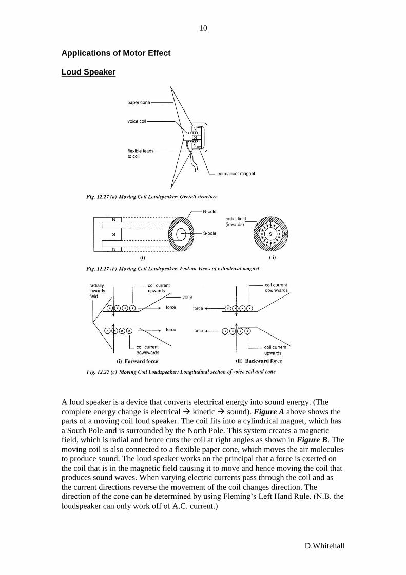
Applications of Motor Effect Loud Speaker
A loud speaker is a device that converts electrical energy into sound energy. (The
complete energy change is electrical kinetic sound). Figure A above shows the
parts of a moving coil loud speaker. The coil fits into a cylindrical magnet, which has
a South Pole and is surrounded by the North Pole. This system creates a magnetic
field, which is radial and hence cuts the coil at right angles as shown in Figure B. The
moving coil is also connected to a flexible paper cone, which moves the air molecules
to produce sound. The loud speaker works on the principal that a force is exerted on
the coil that is in the magnetic field causing it to move and hence moving the coil that
produces sound waves. When varying electric currents pass through the coil and as
the current directions reverse the movement of the coil changes direction. The
direction of the cone can be determined by using Fleming’s Left Hand Rule. (N.B. the
loudspeaker can only work off of A.C. current.)

D.Whitehall
11
Electric Motor
A motor is a machine that converts electrical into mechanical / kinetic energy.
The diagram above is an example of a simple direct current (d.c.) electric motor. It
consists of a rectangular coil of wire that is mounted on an axle so that it can rotate
between the C shaped magnets. The ends of the coil are soldered onto two halves of a
copper split ring commutator. The two carbon brushes shown in the diagram press
against the commutators and are then connected to the electrical circuit. (Some
electric motors have no brushes and are referred to as brushless induction motors.)
How the d.c. motor works?
Suppose the coil is in the horizontal position when the current is turned on, then the
current will flow through the coil in the direction shown and the side PQ of the coil
would experience an upward force and the side RS a downward force. We can
determine these directions by using Fleming Left Hand Rule. These two forces form a
couple that cause the coil to rotate in a clockwise direction until it reaches a vertical
position. At this point the brushes are in the space between the commutator’s halves
and the current is cut off. Because of the momentum the coil does not come to a
complete rest, but continues to move forward past the vertical position. The
commutator halves automatically change contact from one brush to another, which
reverses the direction of the forces on both sides of the coil. The side PQ which is
now on the right hand side experiences a downward force while the side RS which is
now on the left hand side experiences an upward force. Therefore, the coil continues
to move in a clockwise direction.
D.Whitehall
12
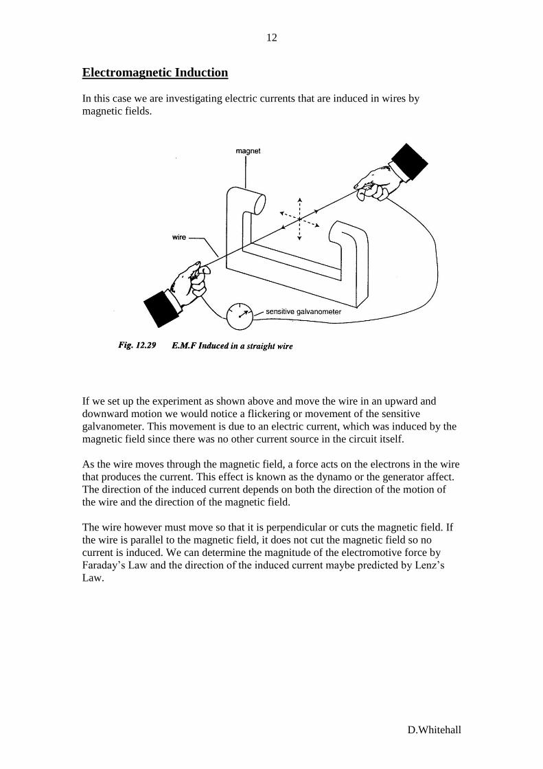
Electromagnetic Induction
In this case we are investigating electric currents that are induced in wires by
magnetic fields.
If we set up the experiment as shown above and move the wire in an upward and
downward motion we would notice a flickering or movement of the sensitive
galvanometer. This movement is due to an electric current, which was induced by the
magnetic field since there was no other current source in the circuit itself.
As the wire moves through the magnetic field, a force acts on the electrons in the wire
that produces the current. This effect is known as the dynamo or the generator affect.
The direction of the induced current depends on both the direction of the motion of
the wire and the direction of the magnetic field.
The wire however must move so that it is perpendicular or cuts the magnetic field. If
the wire is parallel to the magnetic field, it does not cut the magnetic field so no
current is induced. We can determine the magnitude of the electromotive force by
Faraday’s Law and the direction of the induced current maybe predicted by Lenz’s
Law.

D.Whitehall
13
Faraday’s 2nd Law of Electromagnetic Induction
The magnitude of the induced e.m.f. between the ends of the conductor is directly
proportional to the rate of change of the magnetic flux experienced by it.
We can increase the magnitude of the e.m.f. by increasing:
1. the speed of the magnetic or conductor
2. the strength of the magnetic field.
3. the area of the conductor
4. the number of turns on the conductor.
Lenz’s Law The law states that the direction of the induced current is such as to oppose the change
that is causing it. This law can be used to predict the direction of induced current. In
the diagram below as the magnet approaches the magnet at end A of the coil with the
North pole first, the induced current flows in the direction which makes the coil
behaves like a magnet with end A acting as a North Pole. The inward motion of the
magnet is opposed.
When the magnet is withdrawn, the end A of the coil becomes a South Pole and
attracts the receding North Pole of the magnet, so hindering its removal. The induced
current is therefore in the opposite direction to that when the magnet approaches.
D.Whitehall
14
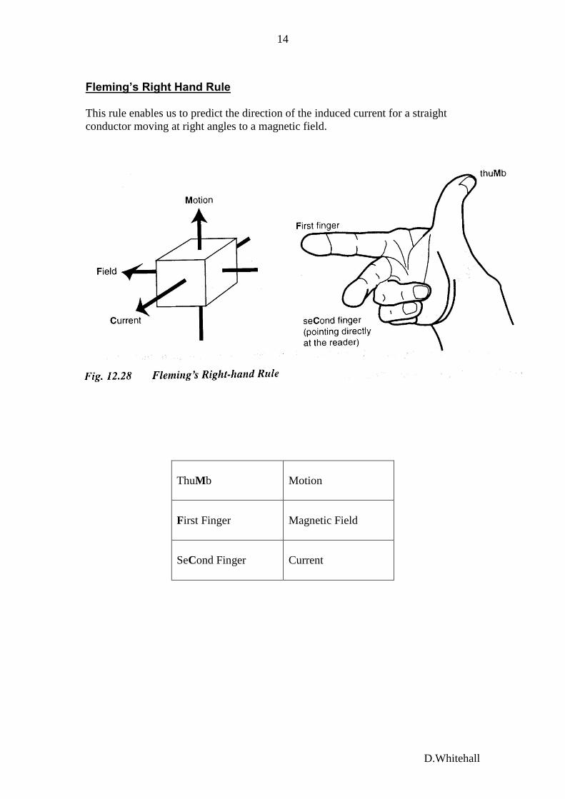
Fleming’s Right Hand Rule
This rule enables us to predict the direction of the induced current for a straight
conductor moving at right angles to a magnetic field.
ThuMb
Motion
First Finger
Magnetic Field
SeCond Finger
Current

D.Whitehall
15
A.C. Generator A generator is a machine used to convert mechanical energy into electrical energy.
The diagram below shows a simple form of an alternating current generator. It
consists of a rectangular coil between the poles of a C-shaped magnet. Each end of the
coil is connected to a slip ring mounted on an axle against which carbon brushes
press.
When the coil rotates, it cuts the magnetic field lines and an e.m.f. is induced into it.
We can use Fleming’s Right Hand Rule to determine the induced current. Diagram A
below shows how the e.m.f. varies with time and Diagram B shows the position of the
coil which corresponds to the points P, Q, R, S and T on Diagram A.
D.Whitehall
16
When the coil is moving through the vertical position, the line s of the magnetic fields
are not cut, hence the e.m.f. is zero. On the other hand when the coil is moving
through the horizontal position, the rate at which the lines of magnetic field are being
cut at the sides of the coil is at the greatest and hence the induced e.m.f. is maximum.
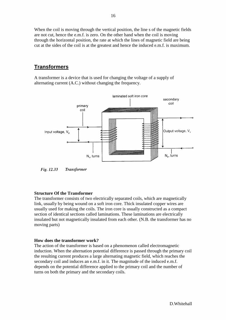
Transformers
A transformer is a device that is used for changing the voltage of a supply of
alternating current (A.C.) without changing the frequency.
Structure Of the Transformer The transformer consists of two electrically separated coils, which are magnetically
link, usually by being wound on a soft iron core. Thick insulated copper wires are
usually used for making the coils. The iron core is usually constructed as a compact
section of identical sections called laminations. These laminations are electrically
insulated but not magnetically insulated from each other. (N.B. the transformer has no
moving parts)
How does the transformer work? The action of the transformer is based on a phenomenon called electromagnetic
induction. When the alternation potential difference is passed through the primary coil
the resulting current produces a large alternating magnetic field, which reaches the
secondary coil and induces an e.m.f. in it. The magnitude of the induced e.m.f.
depends on the potential difference applied to the primary coil and the number of
turns on both the primary and the secondary coils.

D.Whitehall
17
Efficiency of the Transformer
A well-designed transformer is a very efficient (99% efficient). This is due to the fact
that the transformer has no moving parts hence energy is not lost to fictions. However
there are electrical and magnetic factors that can affect the efficiency of transformers.
The table below gives the causes of power loss as steps that can be taken in the design
of the transformer to reduce them.
The Ideal Transformer
No real transformer is 100% efficient, but many in everyday use have high
efficiencies. In order to perform theoretical and practical calculations we need to
develop a concept of an “ideal” transformer. An ideal transformer can therefore be
defined as one for which the input and the output powers are equal.
POUT = PIN
Recall that the secondary circuit is the output circuit and the primary circuit is the
input circuit of the transformer. Therefore we can write:
Ps = Pp
Hence ISVS = IPVP
Rearranging the equation we can state that for an ideal transformer
VS = IP
VP IS

D.Whitehall
18
We can further state:
VS = NS
VP NP
where NS and NP are the number of turns which make up the secondary and primary
coils respectively. (NS/NP is called the terms ratio and determines how large or how
small the secondary voltage of the ideal transformer is in relation to the primary
voltage)
Hence for the step up transformer where VS VP. We can state that
VS = IP = NS 1
VP IS NP
For the step down transformer where VS VP. We can state that
VS = IP = NS 1
VP IS NP
Example
A transformer has 100 turn on its primary coil and 10 000 turns on its secondary coil.
An alternating current of 5A flows though the primary coil when it is connected to a
12V supply.
a) State the type of transformer that is used in the example.
b) Calculate the power input of the transformer.
c) Calculate the e.m.f. induced across the secondary coil.
d) Calculate the maximum current that can flow through the secondary coil.
Assuming that the transformer is 100% efficient.
Read only:
PFC Page 306 - 308
Transformers and transmission of
electrical power.