Embed Size (px)
Citation preview

DESCRIPTIONMagnetically coupled liquid level indicators, or MLIs, are in widespread use throughout process industries. Originally designed as an alternative to sight and gauge glass devices, the MLI is now commonly used in both new construction and plant expansion.
ORION INSTRUMENTS® Atlas, Gemini, and Aurora® magnetic level indicators are precision engineered and manufactured to indicate liquid level accurately, reliably, and continuously. These units are completely sealed and require no periodic maintenance. MLIs also eliminate vapor or liquid emission problems common with sight and gauge glasses.
To complement these products, Orion produces a complete range of level switches and transmitters, including the Eclipse® Guided Wave Radar transmitter from Magnetrol International.
• Numerous chamber styles (or configurations) for eachdesign. Custom designs available.
• Complete range of level switches and level transmitters,including Eclipse Guided Wave Radar
• Fabricated, non-magnetic chamber assembly produced ina wide range of metal and plastic materials
• ANSI and EN 1092 process connections available
• Precision manufactured float with internal magnets andmagnetic flux ring
• Flag or shuttle type indicator with stainless steel scale tomeasure height, volume, or percentage of level
• Standard float stop springs at top and bottom of chamber
• Exceptional code qualified welding
FEATURES
• Feedwater heaters
• Industrial boilers
• Oil/water separators
• Flash drums
• Surge tanks
• Gas chillers
• Deaerators
• Blowdown flash tanks
• Hot wells
• Vacuum tower bottoms
• Alkylation units
• Boiler drums
• Propane vessels
• Storage tanks
APPLICATIONS
Magnetic Level Indicators
M.S. Jacobs & Associates, Inc. | 800-348-0089 | www.msjacobs.com
MAGNETIC LEVEL INDICATOR | OVERVIEW
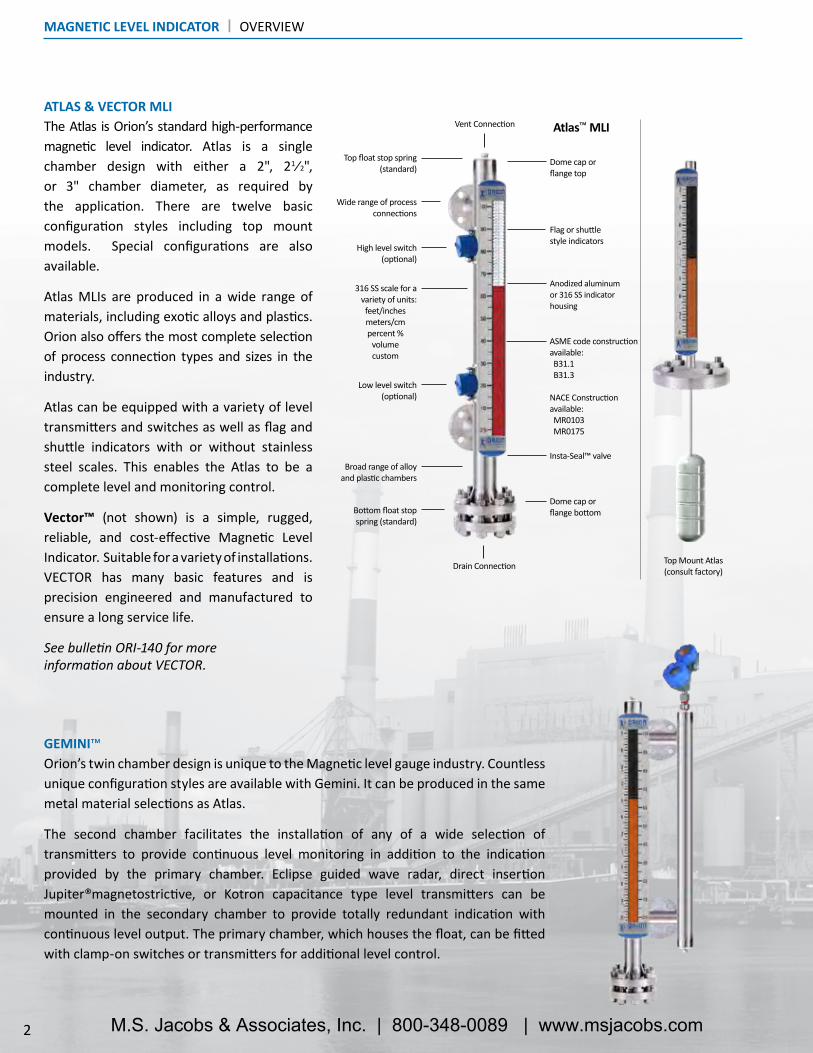
The Atlas is Orion’s standard high-performance magnetic level indicator. Atlas is a single chamber design with either a 2", 21⁄2", or 3" chamber diameter, as required by the application. There are twelve basic configuration styles including top mount models. Special configurations are also available.
Atlas MLIs are produced in a wide range of materials, including exotic alloys and plastics. Orion also offers the most complete selection of process connection types and sizes in the industry.
Atlas can be equipped with a variety of level transmitters and switches as well as flag and shuttle indicators with or without stainless steel scales. This enables the Atlas to be a complete level and monitoring control.
Vector™ (not shown) is a simple, rugged, reliable, and cost-effective Magnetic Level Indicator. Suitable for a variety of installations. VECTOR has many basic features and is precision engineered and manufactured to ensure a long service life.
See bulletin ORI-140 for more information about VECTOR.
GEMINI™Orion’s twin chamber design is unique to the Magnetic level gauge industry. Countless unique configuration styles are available with Gemini. It can be produced in the same metal material selections as Atlas.
The second chamber facilitates the installation of any of a wide selection of transmitters to provide continuous level monitoring in addition to the indication provided by the primary chamber. Eclipse guided wave radar, direct insertion Jupiter®magnetostrictive, or Kotron capacitance type level transmitters can be mounted in the secondary chamber to provide totally redundant indication with continuous level output. The primary chamber, which houses the float, can be fitted with clamp-on switches or transmitters for additional level control.
ATLAS & VECTOR MLIVent Connection
Broad range of alloy and plastic chambers
Wide range of process connections
Dome cap or flange top
Flag or shuttle style indicators
316 SS scale for a variety of units:feet/inchesmeters/cmpercent %
volumecustom
Insta-Seal™ valve
Dome cap or flange bottom
Top float stop spring (standard)
High level switch(optional)
Drain Connection
Low level switch(optional)
Bottom float stop spring (standard)
ASME code construction available: B31.1 B31.3
NACE Construction available: MR0103 MR0175
Anodized aluminum or 316 SS indicator housing
Top Mount Atlas(consult factory)
2
Atlas™ MLI
M.S. Jacobs & Associates, Inc. | 800-348-0089 | www.msjacobs.com

Eclipse® GWRLevel Transmitter
Float
GWR Probe
Baffle PlateVisual
Indicator
Top View
• Wide range of alloy materials
• Eclipse available with HART®, FOUNDATION fieldbus™, or PROFIBUS™ communication
• Large selection of process connection options
• Eight probe designs cover a broad range of applications
• Eclipse transmitter available in 316 stainless steel or epoxy-coated aluminum
• ASME B31.1, B31.3, or NACE available; 150# to 2500# ANSI (PN 16 to PN 320)
• Top and bottom float stop springs
AURORA® FEATURES
DESCRIPTION
Gas BypassZone
OVERVIEW | AURORA® MAGNETIC LEVEL INDICATOR
See Brochure ORI-101 for more information
Aurora’s patented design is the next generation of magnetic level indicators. It is state of the art and reflects Orion’s innovation and commitment to magnetic level indicators.
Aurora is a totally redundant monitoring and control system. Liquid levels are tracked with great accuracy using two different technologies. An Eclipse® guided wave radar probe is housed along with the MLI float in a 3" or 4" diameter chamber. While the indicator relies upon the float and its internal magnets to activate the flags or shuttle, the Eclipse measures the liquid level directly. Two completely separate technologies in a single external chamber equal redundancy unlike any other MLI. The use of a special baffle within the chamber ensures that the float and Eclipse® probe work seamlessly and without interference.
There are ten basic configuration styles and over fifteen material selections for Aurora. For the first time ever, the ability to accurately and reliably measure ultra low dielectric media, high pressure/high temperature process conditions, and media with shifting and changing dielectric values can be accomplished with Aurora.
3M.S. Jacobs & Associates, Inc. | 800-348-0089 | www.msjacobs.com

The patented REVEAL™ indicator incorporates a positive-stop design which limits the rotation of each flag to a half-turn. This eliminates “over-flipping” which is commonly seen on other indicator designs.
Scale Options:• Inches / Feet• Running Inches• Millimeters / Meters• Centimeters / Meters• Percent (5% increments)• Gallons• Liters
1
2
3
4
5
Sing
le S
cale
Dual
Sca
le
Standard flag and shuttle offering. Custom colors available.Each flag contains a high- strength magnet
InstaSeal™ valve allows for an effective vacuum seal
Double custom D-ring endplug ensures a reliable seal that keeps moisture out
All-metal high contrast powder coated or anodized flags are wider to enhance overall visibility
Robust 316 stainless steel enclosure designed to face the elements
Extruded shatter-resistant viewing window enhances visibility and allows the flags to position closely to the float, enhancing the magnetic coupling
1
2
3
4
5
+ 60 m (200 �.)
viewing angle140°
4 M.S. Jacobs & Associates, Inc. | 800-348-0089 | www.msjacobs.com

The float’s 360° magnet assembly produces a strong and consistent flux array allowing visual indication through chambers as thick as schedule 160.
ORION FLOAT TECHNOLOGY
CAPABILITIES
Weld Ring: Secures float cap to main body
Flux Ring: Absorbs magnetic energy and directs it outward
Magnets: A full array surrounds the float with a strong and consistent magnetic field
OPTIONS
• Process pressures up to 4,500+ psig (310 bar) �
• Process Temperatures up to 1,000 °F (538 °C) �
• Total level specific gravities as low as 0.25 �
• Interface float designs available for liquid specific gravity differentials as little as 0.1
• Adequate buoyancy to operate effectively and freely in many viscous liquids, including crude oil
Support Ring: Provides reinforcement for the main float body
Float Body: Robust and durable construction delivers many years of reliable operation
• Teflon-S® PTFE and PFA slip-assistant coating
• Special coatings for abrasion and chemical resistance
• Float retrieval hook
• Float Projection Curve: If the liquid density changes, a float curve will reveal the offset
Float Projection Curve
The float contained within the magnetic level indicator is perhaps the most important element of the instrument. Its structural design, volume displacement, weight, and buoyancy force are all carefully considered when a float is specified for a particular application.
Orion engineers have designed and tested hundreds of floats to gather the most accurate data available. We have designs for thousands of unique applications around the world, including high pressure, high temperature, and interface.
FLOAT | MAGNETIC LEVEL INDICATOR
5
Maximum capabilities can vary depending on combination of pressure, temperature, and media specific gravity.
�
M.S. Jacobs & Associates, Inc. | 800-348-0089 | www.msjacobs.com

Design Atlas, Aurora – single chamber
Gemini – dual chamber
Materials of construction – MLI Metal alloys 316/316L or 304/304L stainless steel,
321 stainless steel, 347 stainless steel,
Titanium, Monel, Hastelloy B,
Hastelloy C-276, Inconel 625, Inconel 825,
Alloy 20, Electropolished 316 stainless steel,
904L stainless steel and other non-magnetic alloys
Materials of construction – Float Varies per application - stainless steel and titanium are standard (exotic alloys available)
Construction options Conformance to Industrial Grade, ASME B31.1, ASME B31.3, ASME (U, UM, S, R), PED and
NACE available
Certified material test reports (CMTR) Available upon request
Pressure class ratings ANSI 150#, 300#, 600#, 900#, 1500#, 2500#
DIN PN16, PN25, PN40, PN63, PN100, PN160, PN250, PN320
Process connection sizes 1⁄2" to 8"
DN 20 to DN 150
Process connection types MNPT, FNPT, Weldolet®, Sockolet®, threaded nipple, buttweld nipple, plain-end nipple,
slip-on flanges, weldneck flanges, lap joint flanges, Tri-Clamp® fitting
Measuring range 12 to 600 in (30 to 1524 cm)
Temperature range -320 to +1000 °F (-196 to +538 °C)
Pressure range Full vacuum to 4500 psig (310 bar)
Specific gravity range As low as 0.25 S.G. (consult factory for lower specific gravities)
Visual Indicators Magnetically actuated flag assembly in contrasting orange/black, yellow/black,
red/white colors, or high visibility shuttle follower (custom colors available)
REVEAL™ Flag assembly seal Inert gas filled and sealed with double D-ring & InstaSeal™ valve
REVEAL™ visual indicator Visible from 200 feet (61 meters)
Aluminum visual indicator Visible from 100 feet (30.5 meters)
Scale options Etched stainless steel with either height, volume, or percentage units (custom markings avail.)
Switch options Model OES electric cam operated snap action (refer to Orion bulletin: OES-100)
Model ORS electric reed type (refer to Orion bulletin: ORS-300)
Pneumatic switch available (consult factory)
Transmitter options Model 706 Eclipse® guided wave radar (refer to Magnetrol bulletin: 57-106)
Model JM4 Jupiter® Magnetostrictive (refer to Orion bulletin: ORI-150)
Model OCT analog reed chain (refer to Orion bulletin: OCT-400)
High temperature options Electric or steam tracing with or without special high temperature insulation
Low temperature options Cryogenic insulation with special polymeric frost extension
MAGNETIC LEVEL INDICATOR | SPECIFICATIONS
6 M.S. Jacobs & Associates, Inc. | 800-348-0089 | www.msjacobs.com

HIGH-TEMPERATURE INSULATIONOrion specializes in custom fiberglass insulation blankets for MLIs of all shapes and sizes. They are constructed with high-quality materials capable of constant contact with temperatures up to 1,000 °F (538 °C). This insulation is available as personnel protection or with heat tracing options for freeze protection or process temperature maintenance.
CRYOGENIC INSULATION & FROST EXTENSIONTo facilitate operation where the product is kept cold via chillers, refrigerants, and condensers, cryogenic insulation is provided. By insulating the MLI with a specialized cryogenic jacket, process temperatures can be maintained in the liquid state down to -320 °F (-196 °C).
A frost extension option is available to prevent ice from collecting on the visual indicator, thereby decreasing the visibility. The extension is constructed of du-rable acrylic plastic and is provided standard with all cryogenic insulation.
MAGNETIC PARTICLE TRAPMagnetic Particle Traps, or Magtraps, provide protection for Orion’s line of Magnetic Level Indicators. Particles composed mostly of ferrite, often from car-bon steel piping, are widespread throughout process piping. These particles enter the MLI via the process connections during normal fill and drain opera-tions. The magnetic float located inside the MLI attracts these particles over time. Eventually, the build-up will be enough to cause the float to become stuck inside the chamber. This results in the MLI either reading inaccurately or not at all. The trap collects the particles which can be cleaned periodically to ensure continued operation of the magnetic level indicator.
HEAT TRACING: ELECTRIC & STEAMFor applications where process freeze protection or temperature maintenance is required, heat tracing will allow the MLI to operate uninterrupted through-out harsh, cold conditions.
Electric Heat Tracing is available in self-regulating, constant wattage, and min-eral insulated varieties. Contact the factory for more information.
OPTIONS & ACCESSORIES | MAGNETIC LEVEL INDICATOR
7M.S. Jacobs & Associates, Inc. | 800-348-0089 | www.msjacobs.com

TRANSMITTER SPECIFICATIONSOCT Reed Chain
Measuring Range: 6 to 198 inches (15 to 503 cm)
Resolution: ±0.50 inches (13 mm)
Repeatability: < 0.25 inches (6 mm)
Non-Linearity: <0.4% full span averaged over span
Upper Transition Zone: 4 inches (10.2 cm)
Lower Transition Zone: 4 inches (10.2 cm)
Power Input: 12 to 36 VDC
Signal Output: 4 to 20 mA
Housing Type: NEMA 4X, IP66
Housing Material: Cast Aluminum or 316 SS
Area Classifications: FM/CSAEP
Process Temperature: -40 to +425 °F (-40 to +218 °C)
Ambient Temperature at Electronics:
-40 to +158 °F (-40 to +70 °C)
Mounting Arrangement: External mount probe with integral top or bottom mounted electronics
Eclipse® Jupiter® on Atlas™
OCT on Atlas™
8
TRANSMITTER SPECIFICATIONSEclipse® Model 706 Guided Wave Radar Jupiter® Model JM4 Magnetostrictive
Measuring Range: 6 to 240 inches (15 to 610 cm) 6 to 400 inches (15 to 999 cm)
Resolution: 0.003 mA analog1 mm digital display .014” (.4 mm)
Repeatability: <0.1 inch (2.5 mm) ±0.005% of full span or 0.014 inches (0.356 mm)(whichever is greater)
Linearity: <0.1% of probe length or 0.1 inch (2.5 mm)(whichever is greater)
0.030 inches (0.8 mm) or 0.01% of probe length(whichever is greater)
Upper Dead Zone: None less than 3 inches (7.6 cm) when bottom mounted electronics
Lower Dead Zone: None less than 3 inches (7.6 cm) when top mounted electronics
Damping: 0 - 10 seconds; adjustable 0 – 10 seconds; adjustable
Power (at terminals):GP/IS/EP: 11 to 36 VDC
FOUNDATION fieldbus™ & PROFIBUS PA™(FISCO): 9 to 17.5 VDCModbus: 8 to 30 VDC
HART®: 16 to 36 VDCFOUNDATION fieldbus™ Explosion Proof: 9 to 17.5 VDC
FISCO/FNICO: 9 to 32 VDC
Signal Output:
4-20 mA with HART®: 3.8 to 20.5 mA usableFOUNDATION fieldbus™: H1 (ITK Ver. 5.01)
PROFIBUS PA™: PROFIBUS PA™ H1 Modbus
4-20 mA with HART®: 3.8 to 20.5 mA usableFOUNDATION fieldbus™: H1 (ITK Ver. 6.1.1)
Display: Graphic liquid crystal display Graphic liquid crystal display
Housing Material: IP67/die-cast aluminum A413 (<0.4% copper); optional stainless steel
IP67/die-cast aluminum A413 (<0.4% copper); optional stainless steel
Area Classifications: USA/Canada/ATEX/IECEx/INMETRO/Korea XP, IS, NI, DIP(see specific product literature for more detail)
USA/Canada/ATEX/IECEx/INMETRO/Korea XP, IS, NI, DIP(see specific product literature for more detail)
Safety Integrity Level: Safe Failure Fraction = 93% (HART only)Functional Safety to SIL 2 as 1oo1 in accordance with IEC 61508 SIL rating pending
Process Temperature: probe dependent(see specific product literature for more detail)
External Mount: -320 to +850 °F (-195 to +455 °C) *with insulationDirect Insertion: -320 to +800 °F (-196 to +425 °C)
Ambient Temperature at Electronics:
-40 to +175 °F (-40 to +80 °C)LCD: -5 to +160 °F (-20 to +70 °C)
-40 to +175 °F (-40 to +80 °C)LCD: -5 to +160 °F (-20 to +70 °C)
Process Pressure: probe dependent(see specific product literature for more detail)
Direct insertion: Vacuum to +3000 psig (207 bar)(see specific product literature for more detail)
Mounting Arrangement:
Direct insertion probe with integral mount or remote mount electronics
Direct insertion probe with integral mount or remote mount electronics
LEVEL TRANSMITTERS | SPECIFICATIONS
M.S. Jacobs & Associates, Inc. | 800-348-0089 | www.msjacobs.com

PNEUMATIC SWITCH SPECIFICATIONS
Consult factory for more information regarding pneumatic switches.
SPECIFICATIONS | POINT LEVEL SWITCHES
ELECTRONIC SWITCH SPECIFICATIONSModel: OES ORS
Description: DPDT magnetically actuated, bi-stable cam drive snap action switch Hermetically sealed bi-stable reed switch
Supply Voltage: 250VAC/24VDC max 250VAC/150VDC maxMaximum Dead Band: ±0.75" float travel ±0.50" float travel
Temperature Range: -58 to +392 °F (-50 to +200 °C) with insulation >250 °F (121 °C)
-58 to +482 °F (-50 to +250 °C) with insulation >250 °F (121 °C)
Enclosure Rating: NEMA 4X NEMA 4XEnclosure Material: Cast aluminum (standard) Stainless steel
9
AGENCY APPROVALS | POINT LEVEL SWITCHES & REED CHAIN TRANSMITTER
Agency Model Area Classification
FM OES-xxxx-001 Class I, II, III, Div. 1, Groups B,C,D,E,F,G; T6 @ 80°C; Type 4XORS-xxxx-001 Class I, II, III, Div. 1, Groups B,C,D,E,F,G; T6 @ 80°C; Type 4X
Class I, Div. 2, Groups A, B, C, & D; T6 @ 80°COCT-xxxx-xxx Class I, II, III, Div. 1, Groups B,C,D,E,F,G; T6 @ 80°C; Type 4X
Class I, Div. 2, Groups A, B, C, & D; T6 @ 80°C
CSA OES-x1xx-001 Class I, Div. 1/2, Groups B, C, & D; T6 @ 80°C; Type 4X Class II, Groups E, F, & G;T6 @ 80°C; Type 4X
Class IIIORS-x1xx-001 Class I, Div. 1, Groups B, C, & D; T6 @ 80°C; Type 4XOCT-xxxx-001 Class I, Div. 2, Groups A, B, C, & D; T6 @ 80°C; Type 4X
Class II, Groups E, F, & G; T6 @ 80°C; Type 4XClass III
ATEX ORS-xAxx-001 ATEX II 2 G Ex d IIC T6 Ta = -40 to +70 °C
IEC ORS-xAxx-001 IECEx d IIC T6 Ta = -40 to +70 °C
CE OES-xxxx-001 Low Voltage Directives, 2006/95/ECORS-xxxx-001 Installation Category II, Pollution Degree 2OCT-xxxx-xxxx
0344
Model OES Model ORS
M.S. Jacobs & Associates, Inc. | 800-348-0089 | www.msjacobs.com

ECLIPSE MODEL 706 LEVEL TRANSMITTER | AGENCY APPROVALS
10
These units are in compliance with the EMC-directive 2014/30/EU, the PED-directive 2014/68/EU and the ATEX directive 2014/34/EU.
Explosion Proof (with intrinsically Safe Probe) • US/Canada:Class I, Div 1, Group B, C and D, T4 Class I, Zone 1 AEx d/ia [ia IIC Ga] IIB + H2 T4 Gb/Ga Class I, Zone 1 Ex d/ia [ia IIC Ga] IIB + H2 T4 Gb/Ga Ta = -40°C to +70°CType 4X, IP67
Flame Proof ATEX – FM14ATEX0041X:II 2/1 G Ex d/ia [ia IIC Ga] IIB + H2 T6 to T1 Gb/GaTa = -40°C to +70°CIP67
IEC- IECEx FMG 14.0018X:Ex d/ia [ia IIC Ga] IIB + H2 T6 to T1 Gb/GaTa = -40°C to +70°CIP66/67
Non- Incendive • US/Canada:Class I, II, III, Division 2, Group A, B, C, D, E, F, G, T4 Class I, Zone 2 AEx ia/nA [ia Ga] IIC T4 Ga/Gc Class I, Zone 2 Ex ia/nA [ia Ga] IIC T4 Ga/Gc Ta = -40°C to +70°CType 4X, IP67
ATEX – FM14ATEX0042X:II 1/3 G Ex ia/nA [ia Ga] IIC T4 Ga/Gc Ta = -15°C to +70°CIP67
IEC – IECEx FMG 14.00018X:Ex ia/nA [ia Ga] IIC T4 Ga/Gc Ta = -15°C to + 70°CIP66/67
Intrinsically Safe • US/Canada:Class I, II, III, Div 1, Group A, B, C, D, E, F, G, T4, Class I, Zone 0 AEx ia IIC T4 GaClass I, Zone 0 Ex ia IIC T4 Ga Ta =-40°C to + 70°CType 4X, IP67
ATEX – FM14ATEX0041X:II 1 G Ex ia IIC T4 Ga Ta = -40°C to +70°CIP67
IEC – IECEx FMG 14.0018X:Ex ia IIC T4 Ga Ta = -40°C to +70°CIP66/67
Dust Ignition Proof • US/Canada:Class II, III, Division 1, Group E, F and G, T4 Ta = -40°C to +70°CType 4X, IP67
ATEX – FM14ATEX0041X:II 1/2 D Ex ia/tb [ia Da] IIIC T85°C to T450°C Da/DbTa = -15°C to +70°CIP67
IEC – IECEx FMG 14.0018X:Ex ia tb [ia Da] IIIC T75°C to T435°C DbEx ia IIIC T75°C to T435°C DaTa = -15°C to +70°CIP66/67
The following approval standards are applicable:FM3600:2011, FM3610:2010, FM3611:2004, FM3615:2006, FM3616:2011, FM3810:2005, ANSI/ISA60079-0:2013, ANSI/ISA 60079-1:2009, ANSI/ISA 60079-11:2013, ANSI/ISA 60079-15:2012, ANSI/ISA 60079-26:2011, NEMA 250:2003, ANSI/IEC 60529:2004, C22.2 No. 0.4:2009, C22.2 No. 0.5:2008, C22.2 No. 30:2007, C22.2 No. 94:2001, C22.2 No. 157:2012, C22.2 No. 213:2012, C22.2 No. 1010.1:2009, CAN/CSA 60079-0:2011, CAN/CSA 60079-1:2011, CAN/CSA 60079-11:2011, CAN/CSA 60079-15:2012, C22.2 No. 60529:2005, EN60079-0:2012, EN60079-1:2007, EN60079-11:2012, EN60079-15:2010, EN60079-26:2007, EN60079-31:2009, EN60529+A1:1991-2000, IEC60079-0:2011, IEC60079-1:2007, IEC60079-11:2011, IEC60079-15:2010, IEC60079-26:2006, IEC60079-31:2008
SPECIAL CONDITIONS OF USE:1. The enclosure contains aluminum and is considered to present a
potential risk of ignition by impact or friction. Care must be taken during installation and use to prevent impact or friction.
2. The risk of electrostatic discharge shall be minimized at installation, following the directions given in the instructions.
3. Contact the original manufacturer for information on the dimensions of the flameproof joints.
4. For installation with ambient temperature of +70 °C, refer to the manufacturer’s instructions for guidance on proper selection of conductors.
5. WARNING—Explosion Hazard: Do not disconnect equipment when flammable or combustible atmoshpere is present.
6. For IEC and ATEX: To maintain the T1 to T6 temperature codes, care shall be taken to ensure the enclosure temperature does not exceed +70 °C.
7. For U.S. and Canada: To maintain the T4 temperature code, care shall be taken to ensure the enclosure temperature does not exceed +70 °C.
8. Temperature codes for the ratings Ex d/ia [ia IIC] IIB+H2 and Ex ia/tb [ia] IIIC are defined by the following table:
Process Temperature (PT)
Temperature Code-TCG (GAS)
Temperature Code-TCD (Dust)
Up to 75 °C T6 TCD= PT+10K=85 °C
From 75 to 90 °C T5 TCD= PT+10K=100 °C
From 90 to 120 °C T4 TCD= PT+15K=135 °C
From 125 to 185 °C T3 TCD= PT+15K=200 °C
From 185 to 285 °C T2 TCD= PT+15K=300 °C
From 285 to 435 °C T1 TCD= PT+15K=450 °C
Agency Specifications – Explosion Proof InstallationFactory Sealed: This product has been approved by Factory Mutual Research (FM) as a Factory Sealed device.NOTE: Factory Sealed: No Explosion Proof conduit fitting (EY seal) is
required within 18” of the transmitter. However, an Explosion Proof conduit fitting (EY seal) is required between the hazard-ous and safe areas.
M.S. Jacobs & Associates, Inc. | 800-348-0089 | www.msjacobs.com

11
AGENCY APPROVALS | JUPITER® MODEL JM4 LEVEL TRANSMITTER
ADDITIONAL CERTIFICATIONSGOST R Russian Certificate of ConformityGOST Pattern Approval Certificate for Measuring Instruments (Metrology Certificate)GOST R Ex-Proof Certificate of Conformity
These units are in compliance with the EMC directive 2004/108/EC, the PED directive 97/23/EC and the ATEX directive 94/9/EC.
Explosion Proof • US/Canada:FM16US0357X/FM16CA0168XClass I, Div 1, Group B, C and D, T4 Ta = -40°C to +70°C Type 4X, IP67
Flame Proof:Flameproof US/ Canada:Class I, Zone 0/1, AEx db IIB + H2 T1…T6 Ga/Gb (US)Class I, Zone 0/1, Ex db IIB + H2 T1…T6 Ga/GB (Canada) Ta = - 40 C to +70 C IP 67
ATEX FM14ATEX0059X:II 1/2G db IIC T1…T6 Ga/GbTa=-40°C to +70°CIP67
IEC- IEC Ex FMG14.0028XEx db IIC T1…T6 Ga/GbTa=-40°C to +70°CIP67
Non- Incendive • US/Canada:FM16US0357X/FM16CA0168XU.S. - Class I, II, III, Division 2, Group A, B, C, D, E, F, G, T4, Ta = -40°C to 70°C CANADA – Class I, Division 2, Group A,B,C,D T4, Ta = -40°C to 70°C Class I, Zone 2 AEx nA IIC T4 Gc Ta = -15°C to 70°C Class I, Zone 2 Ex nA IIC T4 Gc Ta = -15°C to +70°C Type 4X, IP67
ATEX FM14ATEX0060X: II 3 G Ex nA IIC T4 Gc Ta = -15°C to +70°C IP67
IEC – IECEx FMG 14.00028X: Ex nA IIC T4 Gc Ta = -15°C to + 70°C IP67
Intrinsically Safe • US/Canada:FM16US0357X/FM16CA0168X Class I, II, III, Div 1, Group A, B, C, D, E, F, G, T4, Class I, Zone 0 AEx ia IIC T4 Ga Class I, Zone 0 Ex ia IIC T4 Ga Ta =-40°C to + 70°C Type 4X, IP67
ATEX – FM14ATEX0059X: II 1 G Ex ia IIC T4 Ga Ta = -40°C to +70°C IP67
IEC – IECEx FMG 14.0028X: Ex ia IIC T4 Ga Ta = -40°C to +70°C IP67
Dust Ignition Proof • US/Canada:FM16US0357X/FM16CA0168X Class II, III, Division 1, Group E, F and G, T4 Ta = -15°C to +70°C Type 4X, IP67US/Canada Zone Ratings as follows:Zone 21, AEx tb IIIC T86C…T120C Ta= -15 C to +70 C Db (US)Zone 21, Ex tb IIIC T85C…T120C Ta = -15 C to +70 C Db (Canada)Type 4X, IP67
ATEX – FM14ATEX0059X: II 2 D Ex tb IIIC Db T85°C … T120°C Ta = -15°C to +70°C IP67
IEC – IECEx FMG 14.0028X: Ex tb IIIC Db T85°C … T120°C Ta = -15°C to +70°C IP67
The following approval standards are applicable: FM3600:2011, FM3610:2010, FM3611:2004, FM3615:2006, FM3616:2011, FM3810:2005, ANSI/ISA60079-0:2013, ANSI/ISA 60079-1:2009, ANSI/ISA 60079-11:2013, ANSI/ISA 60079-15:2012, ANSI/ISA 60079-26:2011, NEMA 250:2003, ANSI/IEC 60529:2004, C22.2 No. 0.4:2009, C22.2 No. 0.5:2008, C22.2 No. 30:2007, C22.2 No. 94:2001, C22.2 No. 157:2012, C22.2 No. 213:2012 C22.2 No. 1010.1:2009 CAN/CSA 60079-0:2011 CAN/CSA 60079-1:2011 CAN/CSA 60079-11:2011 CAN/CSA 60079-15:2012, C22.2 No. 60529:2005 EN60079-0:2012, EN60079-1:2014 EN60079-11:2012 EN60079-26:2007 EN60079-15:2010 EN60079-31:2009 EN60529+A1:1991-2000 IEC60079-0:2011 IEC60079-1:2014 IEC60079-11:2011 IEC60079-15:2010 IEC60079-2:2006 IEC60079-31:2008
SPECIAL CONDITIONS OF USE:1. For Explosion-proof installations the I.S. ground terminal shall be connected
to appropriate intrinsically safe ground in accordance with the Canadian Electrical code (CEC) or the national electrical code (NEC). For intrinsically safe installations the I.S. ground terminal does not require grounding.
2. To maintain the T4 temperature code care shall be taken to ensure the enclosure temperature does not exceed +70 °C (+158 °F).
3. The risk of electrostatic discharge shall be minimized at installation, follow-ing the direction given in the instruction.
4. For installation with ambient temperature of +70 °C (+158 °F), refer to the manufacturer’s instructions for guidance on proper selection of conductors.
5. Provisions shall be made to provide transient overvoltage protection to a level not to exceed 119Vdc.
6. WARNING – Explosion Hazard do not disconnect equipment when flam-mable or combustible atmosphere is present
7. When equipment is used in explosive dust atmospheres, the end user shall take precautions so that the thermal effects of the process temperature shall limit the equipment enclosure and probe surface temperatures to not exceed the required installation location temperature and shall be between T85 °C (185 °F) and T120 °C (248 °F).
NOTES:1. For Explosion-proof installations the I.S. ground terminal shall be connected
to appropriate intrinsically safe ground in accordance with the Canadian Electrical code (CEC) or the national electrical code (NEC). For intrinsically safe installations the I.S. ground terminal does not require grounding.
2. Manufacturer’s installation instructions supplied with the protective barrier and the CEC or the NEC must be followed when installing this equipment. Barrier must be certified for Canadian & U.S. installation.
3. Control equipment connected to protective barriers must not use or gener-ate more than 250 VDC or VRMS.
4. Agency approved dust tight seals must be used when transmitter is installed in Class II & III environments.
5. For supply connections, use wire suitable for the operating temperature. 6. Agency approved barriers with linear output characteristics must be used.
M.S. Jacobs & Associates, Inc. | 800-348-0089 | www.msjacobs.com
1 2 3 4 5 6 7 8 9 10 11 12 13 14 15 16 17 18 19 20 21 22 23 24 25
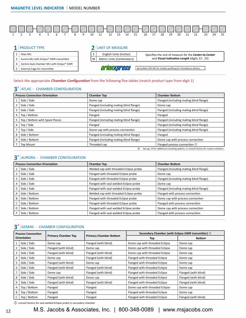
MAGNETIC LEVEL INDICATOR | MODEL NUMBER
1 Atlas MLI
2 Aurora MLI with Eclipse® GWR transmitter
3 Gemini dual-chamber MLI with Eclipse® GWR
5 External Cage for transmitter
1 PRODUCT TYPEE English Units (Inches) Specifies the unit of measure for the Center-to-Center
and Visual Indication Length (digits 23 - 25)M Metric Units (Centimeters)
2 UNIT OF MEASURE
Process Connection Orientation Chamber Top Chamber Bottom1 Side / Side Dome cap Flanged (including mating blind flange)2 Side / Side Flanged (including mating blind flange) Dome cap3 Side / Side Flanged (including mating blind flange) Flanged (including mating blind flange)4 Top / Bottom Flanged Flanged5 Top / Bottom with Spool Pieces Flanged (including mating blind flange) Flanged (including mating blind flange)6 Top / Side Flanged Flanged (including mating blind flange)7 Top / Side Dome cap with process connection Flanged (including mating blind flange)8 Side / Bottom Flanged (including mating blind flange) Flanged9 Side / Bottom Flanged (including mating blind flange) Dome cap with process connectionT Top Mount Threaded cap Flanged process connection �
31 ATLAS - CHAMBER CONFIGURATION
Process Connection Orientation Chamber Top Chamber Bottom1 Side / Side Welded cap with threaded Eclipse probe Flanged (including mating blind flange)2 Side / Side Flanged with threaded Eclipse probe Dome cap3 Side / Side Flanged with threaded Eclipse probe Flanged (including mating blind flange)4 Side / Side Flanged with seal welded Eclipse probe Dome cap5 Side / Side Flanged with seal welded Eclipse probe Flanged (including mating blind flange)A Side / Bottom Welded cap with threaded Eclipse probe Flanged with process connectionB Side / Bottom Flanged with threaded Eclipse probe Dome cap with process connectionC Side / Bottom Flanged with threaded Eclipse probe Flanged with process connectionD Side / Bottom Flanged with seal welded Eclipse probe Dome cap with process connectionF Side / Bottom Flanged with seal welded Eclipse probe Flanged with process connection
32 AURORA - CHAMBER CONFIGURATION
Process ConnectionOrientation Primary Chamber Top Primary Chamber Bottom
Secondary Chamber (with Eclipse GWR transmitter) �Top Bottom
1 Side / Side Dome cap Flanged (with blind) Dome cap with threaded Eclipse Dome cap2 Side / Side Flanged (with blind) Dome cap Dome cap with threaded Eclipse Dome cap3 Side / Side Flanged (with blind) Flanged (with blind) Dome cap with threaded Eclipse Dome cap4 Side / Side Dome cap Flanged (with blind) Flanged with threaded Eclipse Dome cap5 Side / Side Flanged (with blind) Dome cap Flanged with threaded Eclipse Dome cap6 Side / Side Flanged (with blind) Flanged (with blind) Flanged with threaded Eclipse Dome cap7 Side / Side Dome cap Flanged (with blind) Flanged with threaded Eclipse Flanged (with blind)8 Side / Side Flanged (with blind) Dome cap Flanged with threaded Eclipse Flanged (with blind)9 Side / Side Flanged (with blind) Flanged (with blind) Flanged with threaded Eclipse Flanged (with blind)A Top / Bottom Flanged Flanged Dome cap with threaded Eclipse Dome capB Top / Bottom Flanged Flanged Flanged with threaded Eclipse Dome capC Top / Bottom Flanged Flanged Flanged with threaded Eclipse Flanged (with blind)
33 GEMINI - CHAMBER CONFIGURATION
consult factory for seal welded Eclipse probe in secondary chamber�
12
Select the appropriate Chamber Configuration from the following five tables (match product type from digit 1)
See pg. 19 for additional mounting options, or consult factory for custom solutions.�
See bulletin ORI-402 for models qualifying for OrionXpress delivery.
M.S. Jacobs & Associates, Inc. | 800-348-0089 | www.msjacobs.com

1 2 3 4 5 6 7 8 9 10 11 12 13 14 15 16 17 18 19 20 21 22 23 24 25
MODEL NUMBER | MAGNETIC LEVEL INDICATOR
ANSI
A 150#
B 300#
C 600#
D 900#
E 1500#
F 2500#
EN 1092
1 PN 16
2 PN 25
3 PN 40
4 PN 63
5 PN 100
6 PN 160
7 PN 250
8 PN 320
Stainless Steels
A 316/316L Stainless Steel
B 316/316L Stainless Steel w/Carbon Steel Flanges
C 304/304L Stainless Steel
D 304/304L Stainless Steel w/Carbon Steel Flanges
F 317 Stainless Steel
G 321 Stainless Steel
H 347 Stainless Steel
J 904L Stainless Steel
K Electropolished 316 Stainless Steel
Exotic Alloys
N Titanium
P Monel® 400
Q Hastelloy C-276
R Alloy 20
S Inconel® 625
T Incoloy® 825
Carbon Steels (for External Cage product only)
L Carbon Steel
1 Industrial Grade (std.)2 ASME B31.1 for Power Piping Standard3 ASME B31.3 for Process Piping Standard4 Industrial Grade and NACE MR0103A Industrial Grade (extruded outlet)C ASME B31.3 (extruded outlet)
5 Industrial Grade and NACE MR01756 ASME B31.3 for Process Piping Standard and NACE MR01037 ASME B31.3 for Process Piping Standard and NACE MR01758 PED
35 EXTERNAL CAGE FOR JUPITER® DIRECT INSERTION - CHAMBER CONFIGURATIONProcess Connection Orientation Chamber Top Chamber Bottom2 Side / Side Flanged (with threaded Jupiter) Dome Cap3 Side / Side Flanged (with threaded Jupiter) Flanged (including blind flange)8 Side / Bottom Flanged (with threaded Jupiter) Flanged9 Side / Bottom Flanged (with threaded Jupiter) Dome Cap with Spool PieceB Side / Side Flanged (with seal welded Jupiter) Dome CapC Side / Side Flanged (with seal welded Jupiter) Flanged (including blind flange)H Side / Bottom Flanged (with seal welded Jupiter) FlangedJ Side / Bottom Flanged (with seal welded Jupiter) Dome Cap with process connection
4 FLANGE RATING
5
6
MATERIAL SELECTION
CONSTRUCTION CODE
13
A RF Slip-on Flange
B RF Weldneck Flange
C RF Socketweld Flange
D FF Slip-on Flange
F FF Weldneck Flange
Flanged (Alloy)
A RF Slip-on Flange
B RF Weldneck Flange
C RF Socketweld Flange
D FF Slip-on Flange
F FF Weldneck Flange
G FF Socketweld Flange
H RTJ Slip-on Flange
J RTJ Weldneck Flange
K RTJ Socketweld Flange
L RF Lap Joint Flange
Other
M Male Threaded (NPT)
N Female Threaded (NPT)
P Plain-end Nipple
Q Socketweld
R Buttweld
S Weldolet™
T Sockolet™
W Threadolet™
Y Tri-Clamp® Fitting
7 CHAMBER FLANGE STYLE
8 PROCESS CONNECTION TYPE
EN 1092 European Standard
6 EN 1092 Type 11 with Type A Face
7 EN 1092 Type 11 with Type B1 or B2 Face *
8 EN 1092 Type 12 with Type A Face
9 EN 1092 Type 12 with Type B1 or B2 Face *
G FF Socketweld Flange
H RTJ Slip-on Flange
J RTJ Weldneck Flange
K RTJ Socketweld Flange
L RF Lap Joint Flange
EN 1092 European Standard
6 EN 1092 Type 11 with Type A Face
7 EN 1092 Type 11 with Type B2 Face
8 EN 1092 Type 12 with Type A Face
9 EN 1092 Type 12 with Type B2 Face
* B1: if digit 4 = 1, 2,or 3 B2: if digit 4 =4, 5, 6, 7, 8
M.S. Jacobs & Associates, Inc. | 800-348-0089 | www.msjacobs.com

1 2 3 4 5 6 7 8 9 10 11 12 13 14 15 16 17 18 19 20 21 22 23 24 25
MAGNETIC LEVEL INDICATOR | MODEL NUMBER
14
Standard gasket for 150# and 300# flange ratings suitable for most applications.
Standard gasket for 600# and above flange ratings suitable for most applications.
�
�Winding material matches chamber material.�Ring type gasket material matches flange material.�
Standard
A 1⁄2"
B 3⁄4"
C 1"
D 11⁄2"
E 2"
F 21⁄2"
G 3"
H 4"
J 6"
K 8"
EN 1092
1 DN 15
2 DN 20
3 DN 25
4 DN 40
5 DN 50
6 DN 65
7 DN 80
8 DN 100
9 DN 150
Gaskets for Metallic Flanges
A Flexible graphite ring �
B Spiral wound with graphite filler and carbon steel outer ring��
C Spiral wound with graphite filler, inner ring matching chamber material �, and carbon steel outer ring
D RTJ oval ring �
E RTJ octagonal ring �
F Virgin PTFE Ring -140 to +450 °F (-96 to +232 °C)
Stainless Steel
A 304 stainless steel (standard) A193 Gr. B8 Class I / A194 Gr. 8
B 304 stainless steel w/PTFE coating A193 Gr. B8 Class I / A194 Gr. 8
C 316 stainless steel A193 Gr. B8M Class I / A194 Gr. 8M
D 316 stainless steel w/PTFE coating A193 Gr. B8M Class I / A194 Gr. 8M
Alloy Steel
M Alloy Steel A193 Gr. B7 / A194 Gr. 2H
P Alloy Steel A193 Gr. B7M / A194 Gr. 2HM
S Alloy Steel w/zinc plating Available when digit 17=N or T Not available when digit 6= 4, 5, 7 or 8
10 GASKET STYLE9 PROCESS CONNECTION SIZE
11 CHAMBER FLANGE BOLTING
N None (if mating flanges are not supplied)
N None
1 1⁄2"
2 3⁄4"
3 1"
4 11⁄2"
5 2"
6 21⁄2"
7 3"
8 4"
N None
14 DRAIN SIZE
1 1⁄2"
2 3⁄4"
3 1"
4 11⁄2"
5 2"
6 21⁄2"
7 3"
8 4"
N None
12 VENT SIZE
1 FNPT w/ Hex Head Plug (std.)2 Socketweld3 Male Threaded (MNPT)4 Plain-End Nipple5 Buttweld Nipple6 RF Slip On Flange7 RF Weld Neck Flange8 RTJ Slip On Flange9 RTJ Weld Neck Flange
A Ball Valve, FNPT x FNPTB Ball Valve, SW x SWC Ball Valve, SW x FNPTD Gate Valve, FNPT x FNPTE Gate Valve, SW x SWF Gate Valve, SW x FNPTG RF Flange Ball Valve w/spoolH RF Flange Gate Valve w/spool
N None
15 DRAIN TYPE
1 FNPT w/ Hex Head Plug (std.)2 Socketweld3 Male Threaded (MNPT)4 Plain-End Nipple5 Buttweld Nipple6 RF Slip On Flange7 RF Weld Neck Flange8 RTJ Slip On Flange9 RTJ Weld Neck Flange
A Ball Valve, FNPT x FNPTB Ball Valve, SW x SWC Ball Valve, SW x FNPTD Gate Valve, FNPT x FNPTE Gate Valve, SW x SWF Gate Valve, SW x FNPTG RF Flange Ball Valve w/spoolH RF Flange Gate Valve w/spool
N None
13 VENT TYPE
M.S. Jacobs & Associates, Inc. | 800-348-0089 | www.msjacobs.com

1 2 3 4 5 6 7 8 9 10 11 12 13 14 15 16 17 18 19 20 21 22 23 24 25
Jupiter® Magnetostrictive Transmitter(mounting configurations shown below) Jupiter® Only, No switches Jupiter® and at least one
OES/ORS Switch (Clamp-mounted)Jupiter® and at least one
OES/ORS Switch (Rod-mounted)
Top Mount 1 A L
Top Mount Offset/High-Temp 2 B M
Bottom Mount Offset/High-Temp 3 C P
Eclipse® Probe Configuration Eclipse® Only, No switches Eclipse® and at least one OES/ORS Switch (Clamp-mounted)
Eclipse® and at least one OES/ORS Switch (Rod-mounted)
Standard Coaxial Probe 1 A L
Rigid Single Rod Probe 2 B M
Flexible Single Rod Probe 3 C P
Enlarged Coaxial Probe 4 D R
Direct Insertion Transmitter 1
Jupiter® Probe Configuration(Gemini only option if GWR not used) Jupiter® Only, No switches Jupiter® and at least one
OES/ORS Switch (Clamp-mounted)Jupiter® and at least one
OES/ORS Switch (Rod-mounted)
Jupiter, Direct Insertion 9 K W
OCT Reed Chain Transmitter(mounting configurations shown below)
Top Mount 8
Bottom Mount 9
N None
Switches Only (No Transmitter. See options below if transmitter is required)
Y Orion Electronic Switch (OES or ORS) clamp-mounted to chamber
Z Orion Electronic Switch (OES or ORS) with switch mount rod
N None
MODEL NUMBER | MAGNETIC LEVEL INDICATOR
16 ACCESSORY / TECHNOLOGY CODE
FOR ATLAS ONLY WITH EXTERNAL TRANSMITTER (code in first digit of model number must be “1”)
FOR AURORA & GEMINI ONLY (code in first digit of model number must be “2” or “3”)Single rod caged or flexible probes not available with bottom cap
FOR JUPITER® EXTERNAL CHAMBER/CAGE ONLY (code in first digit of model number must be “5”)
17 TEMPERATURE OPTIONS
15
Insulation Blanket for Personnel Protection
A Chamber pipe only up to 600 °F (316 °C)
B Chamber pipe only up to 1000 °F (538 °C)
C Chamber and flanges up to 600 °F (316 °C)
D Chamber and flanges up to 1000 °F (538 °C)
Cryogenic Insulation
L Process temperatures down to -150 °F (-101 °C)
P Process temperatures down to -320 °F (-196 °C)
Insulation Pad for Indicator & Transmitter Protection
Y Indicator only ≥ 250 °F (121 °C)
T Jupiter® 175 to 850 °F (79 to 454 °C)
U OCT 200 to 700 °F (93 to 371 °C)
V Indicator and Jupiter® 250 to 850 °F (121 to 454 °C)
W Indicator and OCT 250 to 700 °F (121 to 371 °C)
Other Options for Temperature Maintenance or Freeze Protection
H Electric Heat Tracing includes insulation blanket
S Steam Tracing (3/8” tubing) includes insulation blanket
J Steam Jacket (1/2” NPT inlet/outlet) includes insulation pad
When MLIs are combined with compatible accessory items, such as continuous transmitters or point switches, minor changes to the chamber and float design may be required. This code captures that relationship.
For digit 16, match up the MLI product type with the appropriate transmitter, switch, or combination of both. The corresponding code should be entered into the model number shown above.
All transmitters and switches must be ordered separately.
M.S. Jacobs & Associates, Inc. | 800-348-0089 | www.msjacobs.com

1 2 3 4 5 6 7 8 9 10 11 12 13 14 15 16 17 18 19 20 21 22 23 24 25
Total Level Measurement
S Fluorescent Orange Shuttle / Follower
1 Orange / Black Flags
2 Yellow / Black Flags
3 Red / White Flags
4 Red / Silver Flags (+700 °F (+371 °C) and above)
A Orange / Black Flags with Yellow Float Diagnostics �
B Yellow / Black Flags with Orange Float Diagnostics �
C Red / White Flags with Yellow Float Diagnostics �
D Red / Silver Flags with Green Float Diagnostics(+700 °F (+371 °C) and above) �
N No Indicator (For use with Jupiter® external cage)
Interface Level Measurement
T Fluorescent Orange Shuttle / Follower
5 Orange / Black Flags
6 Yellow / Black Flags
7 Red / White Flags
8 Red / Silver Flags (+700 °F (+371 °C) and above)
F Orange / Black Flags with Yellow Float Diagnostics �
G Yellow / Black Flags with Orange Float Diagnostics �
H Red / White Flags with Yellow Float Diagnostics �
J Red / Silver Flags with Green Float Diagnostics �(+700 °F (+371 °C) and above) �
X X XSpecify in INCHES when model code 2 is E
Specify in CENTIMETERS when model code 2 is M
Example #1: Center-to-Center is 84 inches. Enter as 084. (model digit 2 must be “E”)
Example #2: Center-to-Center is 124 centimeters. Enter as 124. (model digit 2 must be “M”)
Example #3: Center-to-Center is 124.25 inches. Enter as 124 inches and X the model for 124.25 inches. Or consult factory for assistance.
Example #4: Center-to-Center is 724 millimeters. Enter as 072 centimeters and X the model for 724 millimeters. Or consult factory for assistance.
X X X These codes are factory assigned. �
MAGNETIC LEVEL INDICATOR | MODEL NUMBER
Wide View Stainless Steel indicator
A Foot / Inch Measurement
B Meter / Centimeter Measurement
C Running Inch Measurement
D Percent (0 - 100%) Measurement
E Gallon Measurement
G Meter / Millimeter Measurement
H Foot / Inch with Percent (Dual Scale)
J Meter / Millimeter with Percent (Dual Scale)
F Liter Measurement
P No scale
18 MEASUREMENT TYPE & INDICATOR STYLE
19 INDICATOR HOUSING MATERIAL & SCALE �
20, 21, 22 FACTORY ASSIGNED
23, 24, 25 CENTER-TO-CENTER PROCESS CONNECTION DIMENSION & VISUAL INDICATION LENGTH
16
Float diagnostics is a safety feature which indicates a contrasting color on the visual indicator when the float has fallen below the lowest measurable point on the scale. This can occur when the specific gravity of the liquid drastically decreases or the float collapses due to a pressure spike. (see pg. 4)
�
Anodized Aluminum Housing
1 Foot / Inch Measurement
2 Meter / Centimeter Measurement
3 Running Inch Measurement
4 Percent (0 - 100%) Measurement
5 Gallon Measurement
6 Liter Measurement
7 Meter / Millimeter Measurement
N No scale
Aluminum indicator is required if either of the following conditions are true: a) A glass viewing window is desired instead of shatter-resistant polycarbonate. b) Process operating temperatures exceed above 800 °F (427 °C)
Not all chamber diameters and wall thicknesses are eligible for OrionXpress. Contact the factory or your local representative for more information.
�
�
M.S. Jacobs & Associates, Inc. | 800-348-0089 | www.msjacobs.com

17
CONFIGURATIONS | EXTERNAL CAGE FOR JUPITER® TRANSMITTER
A
B
A
B
Centerto
Center
Centerto
Center
A
CentertoFace
A
CentertoFace
C C
C C
Configuration 2 & B Configuration 3 & C
Configuration 8 & H Configuration 9 & J
M.S. Jacobs & Associates, Inc. | 800-348-0089 | www.msjacobs.com
A
BC
A
B
A
B
A
B
FacetoFace
C
C
VisualIndicationRange
B
Center-to-Face
VisualIndicationRange
VisualIndicationRange
VisualIndicationRange
VisualIndicationRange
VisualIndicationRange
FacetoFace
Centerto
Center
Centerto
Center
Centerto
Center
VisualIndicationRange
B
Center-to-Face
A
CentertoFace
VisualIndicationRange
A
CentertoFace
VisualIndicationRange
BATON ROUGE, LAPHONE 1-225-906-2343F AX 1-225-906-2344
WWW.ORIONINSTRUMENTS.COM
A
B
C C
C
C
C C
A
BC
VisualIndicationRange
1/2 IndicationRange
1/2 IndicationRange
BATON ROUGE, LAPHONE 1-225-906-2343F AX 1-225-906-2344
WWW.ORIONINSTRUMENTS.COM
18
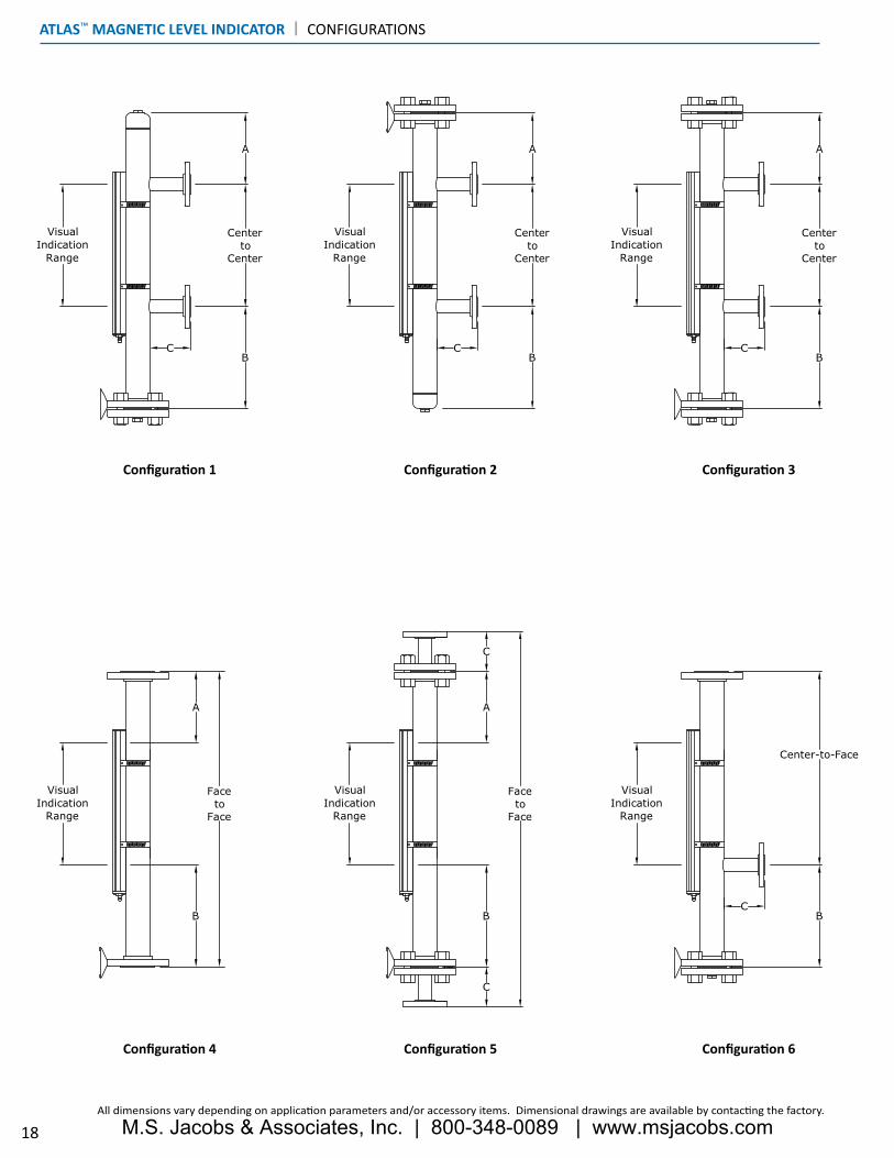
Configuration 4 Configuration 5 Configuration 6
Configuration 1 Configuration 2 Configuration 3
All dimensions vary depending on application parameters and/or accessory items. Dimensional drawings are available by contacting the factory.
ATLAS™ MAGNETIC LEVEL INDICATOR | CONFIGURATIONS
M.S. Jacobs & Associates, Inc. | 800-348-0089 | www.msjacobs.com

A
BC
A
B
A
B
A
B
FacetoFace
C
C
VisualIndicationRange
B
Center-to-Face
VisualIndicationRange
VisualIndicationRange
VisualIndicationRange
VisualIndicationRange
VisualIndicationRange
FacetoFace
Centerto
Center
Centerto
Center
Centerto
Center
VisualIndicationRange
B
Center-to-Face
A
CentertoFace
VisualIndicationRange
A
CentertoFace
VisualIndicationRange
BATON ROUGE, LAPHONE 1-225-906-2343F AX 1-225-906-2344
WWW.ORIONINSTRUMENTS.COM
A
B
C C
C
C
C C
A
BC
VisualIndicationRange
1/2 IndicationRange
1/2 IndicationRange
BATON ROUGE, LAPHONE 1-225-906-2343F AX 1-225-906-2344
WWW.ORIONINSTRUMENTS.COM
19
Multiple Process Connectionsconsult factory
Atlas Top Mountconfiguration T
Atlas Top Mountw/stilling wellconsult factory
Configuration 7 Configuration 8 Configuration 9
Atlas Top Mountw/threaded process
connectionconsult factory
CONFIGURATIONS | ATLAS™ MAGNETIC LEVEL INDICATOR
M.S. Jacobs & Associates, Inc. | 800-348-0089 | www.msjacobs.com

AURORA® MAGNETIC LEVEL INDICATOR | CONFIGURATIONS
VisualIndicationRange
VisualIndicationRange
VisualIndicationRange
A
B
Centerto
Center
VisualIndicationRange
VisualIndicationRange
A
B
Centerto
Center
A
B
Centerto
Center
A
B
Centerto
Center
A
B
Centerto
Center
VisualIndicationRange
VisualIndicationRange
VisualIndicationRange
A A
CentertoFace
C C C
C C
C
CentertoFace
C
A
CentertoFace
C
VisualIndicationRange
VisualIndicationRange
A
CentertoFace
C
A
CentertoFace
C
20
Configuration 4Single rod caged or flexible probes not available with
bottom cap
Configuration 5
Configuration 1 Configuration 2Single rod caged or flexible probes not available with
bottom cap
Configuration 3
All dimensions vary depending on application parameters and/or accessory items. Dimensional drawings are available by contacting the factory.
M.S. Jacobs & Associates, Inc. | 800-348-0089 | www.msjacobs.com

CONFIGURATIONS | AURORA® MAGNETIC LEVEL INDICATOR
VisualIndicationRange
VisualIndicationRange
VisualIndicationRange
A
B
Centerto
Center
VisualIndicationRange
VisualIndicationRange
A
B
Centerto
Center
A
B
Centerto
Center
A
B
Centerto
Center
A
B
Centerto
Center
VisualIndicationRange
VisualIndicationRange
VisualIndicationRange
A A
CentertoFace
C C C
C C
C
CentertoFace
C
A
CentertoFace
C
VisualIndicationRange
VisualIndicationRange
A
CentertoFace
C
A
CentertoFace
C
21
Configuration DSingle rod caged or flexible probes not available with
bottom cap
Configuration F
Configuration A Configuration BSingle rod caged or flexible probes not available with
bottom cap
Configuration C
M.S. Jacobs & Associates, Inc. | 800-348-0089 | www.msjacobs.com

GEMINI™ MAGNETIC LEVEL INDICATOR | CONFIGURATIONS
BATON ROUGE, LAPHONE 1-225-906-2343F AX 1-225-906-2344
WWW.ORIONINSTRUMENTS.COM
BATON ROUGE, LAPHONE 1-225-906-2343F AX 1-225-906-2344
WWW.ORIONINSTRUMENTS.COM
BATON ROUGE, LAPHONE 1-225-906-2343F AX 1-225-906-2344
WWW.ORIONINSTRUMENTS.COM
BATON ROUGE, LAPHONE 1-225-906-2343F AX 1-225-906-2344
WWW.ORIONINSTRUMENTS.COM
BATON ROUGE, LAPHONE 1-225-906-2343F AX 1-225-906-2344
WWW.ORIONINSTRUMENTS.COM
BATON ROUGE, LAPHONE 1-225-906-2343F AX 1-225-906-2344
WWW.ORIONINSTRUMENTS.COM
22
Configuration 4 Configuration 5 Configuration 6
Configuration 1 Configuration 2 Configuration 3
All dimensions vary depending on application parameters and/or accessory items. Dimensional drawings are available by contacting the factory.Single rod caged or flexible probes not available for any Gemini chambers with bottom cap.
M.S. Jacobs & Associates, Inc. | 800-348-0089 | www.msjacobs.com

CONFIGURATIONS | GEMINI™ MAGNETIC LEVEL INDICATOR
BATON ROUGE, LAPHONE 1-225-906-2343F AX 1-225-906-2344
WWW.ORIONINSTRUMENTS.COM
BATON ROUGE, LAPHONE 1-225-906-2343F AX 1-225-906-2344
WWW.ORIONINSTRUMENTS.COM
BATON ROUGE, LAPHONE 1-225-906-2343F AX 1-225-906-2344
WWW.ORIONINSTRUMENTS.COM
BATON ROUGE, LAPHONE 1-225-906-2343F AX 1-225-906-2344
WWW.ORIONINSTRUMENTS.COM
BATON ROUGE, LAPHONE 1-225-906-2343F AX 1-225-906-2344
WWW.ORIONINSTRUMENTS.COM
BATON ROUGE, LAPHONE 1-225-906-2343F AX 1-225-906-2344
WWW.ORIONINSTRUMENTS.COM
23
Configuration ASingle rod caged or flexible probes not available with
bottom cap
Configuration BSingle rod caged or flexible probes not available with
bottom cap
Configuration C
Configuration 7 Configuration 8 Configuration 9
M.S. Jacobs & Associates, Inc. | 800-348-0089 | www.msjacobs.com
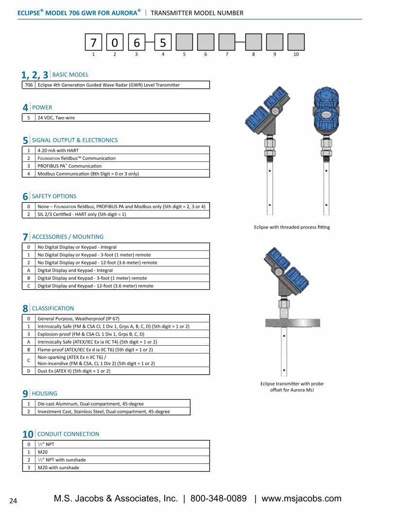
ECLIPSE® MODEL 706 GWR FOR AURORA® | TRANSMITTER MODEL NUMBER
24
Eclipse with threaded process fitting
Eclipse transmitter with probe offset for Aurora MLI
1 2 3 4 5 6 7 8 9 10
7 0 6 5
1, 2, 3 BASIC MODEL706 Eclipse 4th Generation Guided Wave Radar (GWR) Level Transmitter
5 24 VDC, Two-wire
4 POWER
1 4-20 mA with HART2 FOUNDATION fieldbus™ Communication3 PROFIBUS PA™ Communication4 Modbus Communication (8th Digit = 0 or 3 only)
SIGNAL OUTPUT & ELECTRONICS5
0 No Digital Display or Keypad - Integral1 No Digital Display or Keypad - 3-foot (1 meter) remote2 No Digital Display or Keypad - 12-foot (3.6 meter) remoteA Digital Display and Keypad - IntegralB Digital Display and Keypad - 3-foot (1 meter) remoteC Digital Display and Keypad - 12-foot (3.6 meter) remote
7 ACCESSORIES / MOUNTING
0 None – FOUNDATION fieldbus, PROFIBUS PA and Modbus only (5th digit = 2, 3 or 4)2 SIL 2/3 Certified - HART only (5th digit = 1)
6 SAFETY OPTIONS
1 Die-cast Aluminum, Dual-compartment, 45-degree2 Investment Cast, Stainless Steel, Dual-compartment, 45-degree
9 HOUSING
0 General Purpose, Weatherproof (IP 67)1 Intrinsically Safe (FM & CSA CL 1 Div 1, Grps A, B, C, D) (5th digit = 1 or 2)3 Explosion-proof (FM & CSA CL 1 Div 1, Grps B, C, D)A Intrinsically Safe (ATEX/IEC Ex ia IIC T4) (5th digit = 1 or 2)B Flame-proof (ATEX/IEC Ex d ia IIC T6) (5th digit = 1 or 2)
C Non-sparking (ATEX Ex n IIC T6) /Non-incendive (FM & CSA, CL 1 Div 2) (5th digit = 1 or 2)
D Dust Ex (ATEX II) (5th digit = 1 or 2)
8 CLASSIFICATION
0 1⁄2" NPT1 M202 1⁄2" NPT with sunshade3 M20 with sunshade
10 CONDUIT CONNECTION
M.S. Jacobs & Associates, Inc. | 800-348-0089 | www.msjacobs.com

PROBE SPECIFICATIONS | ECLIPSE® MODEL 706 GWR FOR AURORA®
25
ECLIPSE PROBE SPECIFICATIONSGWR
Probe � Description Application Dielectric Range ��
Temperature Range �
Maximum Pressure Vacuum
OverfillSafe
ViscositycP (mPa.s)
Length
7 y TStandard
Temperature Coaxial
Level/Interface εr 1.4–100
-40 to +400 °F(-40 to +200 °C)
1000 psi(70 bar)
Full Yes 500/200024" to 240"
(60 to 610 cm)
7 y P High
Pressure Coaxial
Level/Interface εr 1.4–100
-320 to +400 °F(-196 to +200 °C)
6250 psi(431 bar)
Full Yes 500/200024" to 240"
(60 to 610 cm)
7 y D High Temp. / High Pressure
Coaxial
Level/Interface εr 1.4–100
-320 to +850 °F(-196 to +450 °C)
6250 psi(431 bar)
Full Yes 500/200024" to 240"
(60 to 610 cm)
7 y S Steam Coaxial
Saturated Steam εr 10–100
-40 to +750 °F(-40 to +400 °C)
3000 psi(207 bar)
Full No 50024" to 180"
(60 to 455 cm)
7 y G Standard
Temperature Caged
Level/Interface εr 1.4–100
-40 to +400 °F(-40 to +200 °C)
1000 psi(70 bar)
Yes Yes 1000024" to 240"
(60 to 610 cm)
7 y JHigh Temp. / High Pressure
Caged
Level/Interface εr 1.4–100
-320 to +850 °F(-196 to +450 °C)
6250 psi(431 bar)
Full Yes 1000024" to 240"
(60 to 610 cm)
7 y 6 Flexible Level εr 1.7–100-320 to +850 °F
(-196 to +450 °C)6250 psi(431 bar)
Full Yes 100003' to 100'
(91 cm to 30 m)
� 2nd digit A=English, C=Metric� Minimum εr 1.2 with end of probe analysis enabled� Single rod probes mounted directly into the vessel must be within 3–6 inches of metal tank wall
to obtain minimum dielectric of 1.4; otherwise; εr 1.7.� This depends on the probe spacer material. Refer to model selection for spacer options. ECLIPSE probes containing o-rings can be used for vacuum (negative pressure) service, but only
those probes with glass seals are hermetically sealed to <10-8 cc/sec @ 1 atmosphere helium. Consult factory for longer probe lengths. Consult factory for overfill applications. Overfill capability can be achieved with software.
See Magnetrol bulletin 57-106 for additional information regarding Eclipse guided wave radar speci-fications.
Single Rod ProbeCoaxial Probe
M.S. Jacobs & Associates, Inc. | 800-348-0089 | www.msjacobs.com

ECLIPSE® MODEL 706 GWR FOR AURORA® | PROBE MODEL NUMBER
26
11 1298 10 1413 154 65 71 2 3
7
7A Eclipse GWR probe, English unit of measure7C Eclipse GWR probe, Metric unit of measure
1, 2 BASIC MODEL
D Coaxial High-Temp/Hi-Pressure – Available only with 10th digit N or D
Media dielectric range ≥ 1.4 (2.0 with ceramic spacers)
P Coaxial High Pressure – Available only with 10th digit N or D
S Coaxial Hot water/steam service – Available only with 10th digit N
T Coaxial Overfill/Interface – Not available with 10th digit N or D
G Single Rod Caged ProbeJ Single Rod High-Temp/High-Pressure Caged Probe6 Single Rod Flexible probe Media dielectric range ≥ 1.9
3 PROBE TYPE
0 IndustrialK ASME B31.1L ASME B31.3
M ASME B31.3 & NACE MR0175/MR0103 – NOT available with carbon steel flange
N NACE MR0175/MR0103 – NOT available with carbon steel flange
6 CONSTRUCTION CODES
0 None1 PTFE Spacer2 PEEK HT3 Ceramic – Available only with 3rd digit J
5 Metal Short Circuit
9 SPACER/WEIGHT MATERIAL
1 Offset2 Offset with 1⁄2" NPT Vent3 Offset with 3⁄4" NPT Vent
7 FLANGE OPTIONS
Seal Welded Probe & Flange MaterialA 316 SS/316L SSB Hastelloy CC MonelR 316 SS/316L SS with Carbon Steel FlangeS Hastelloy C with Carbon Steel FlangeT Monel with Carbon Steel Flange
8 MATERIAL OF CONSTRUCTION
0 Viton® GFLT – Available only with 3rd digit G, T or 1
2 Kalrez® 4079 – Available only with 3rd digit G, T or 1
8 Aegis PF128 (NACE) – Available only with 3rd digit G, T or 1
A Kalrez 6375 – Available only with 3rd digit G, T or 1
B HF Acid Probe – Available only with 3rd digit G or T and 8th digit C
D None/Glass Ceramic Alloy (Dual Seal Design with annunciator fitting) – Available only with 3rd digit D or P
N None/Glass Ceramic Alloy – Available only with 3rd digit D or P
10 PROCESS SEAL - O-RING MATERIAL
0 Caged Probe2 Small Coaxial3 Flexible Cable ProbeA Medium Coaxial
11 PROBE SIZE
0 Single Length Probe1 Removable Single Length Cable Probe
12 SPECIAL OPTIONS
13, 14, 15 INSERTION LENGTH
XXX24 to 240 inches (60 to 610 cm) � Example: 24 inches = 024; 160 centimeters = 160
Consult factory for insertion lengths less than 24" (60 cm) or greater than 240" (610 cm).
�
Threaded11 3⁄4" NPT threaded connection
4, 5 PROCESS CONNECTION - SIZE / TYPE
4" ANSI Flanges63 4" 150# RF ANSI Flange64 4" 300# RF ANSI Flange65 4" 600# RF ANSI Flange66 4" 900# RF ANSI Flange67 4" 1500# RF ANSI Flange68 4" 2500# RF ANSI Flange
The Aurora® MLI utilizes the Magnetrol® Eclipse® GWR level transmitter. All probes specified for an Aurora® should be selected from this model number. Consult factory for special requests.
M.S. Jacobs & Associates, Inc. | 800-348-0089 | www.msjacobs.com

Eclipse® Guided Wave Radar
Modulevel® Displacer Controller
Jupiter® Magnetostrictive
AVAILABLE LEVEL TRANSMITTERS | GEMINI™ MAGNETIC LEVEL INDICATOR
The Eclipse® Model 706 High Performance Transmitter is a loop-powered, 24 VDC level transmitter that is based upon the proven and accepted technology of Guided Wave Radar (GWR). Encompassing a number of significant engineering accomplishments, this leading edge level transmitter is designed to provide measurement performance well beyond that of many of the more traditional technologies.
The Digital E3 Modulevel is an advanced, intrinsically safe two-wire instrument utilizing simple buoyancy principle to detect and convert liquid level changes into a stable 4–20 mA output signal. The linkage between the level sensing element and output electronics provides a simple mechanical design and construction.
The Jupiter® Model JM4 Magnetostrictive level transmitter provides a 4–20 mA output proportional to the level being measured or FOUNDATION fieldbus™ output. JUPITER is available as an externally mounted model for use with Orion Atlas™, Gemini™, and Aurora® magnetic level indicators or as a direct insertion version for use in a wide variety of process vessels or external chambers.
27M.S. Jacobs & Associates, Inc. | 800-348-0089 | www.msjacobs.com

28
JUPITER® JM4 MODEL NUMBER | TRANSMITTER MODEL NUMBER
1 2 3 4 5 6 7 8 9 10
J M 4 5
9 HOUSING
1 Aluminum, Dual-Compartment
2 316 SS, Dual-Compartment
10 CONDUIT CONNECTION & SUNSHADE OPTION
0 1⁄2” NPT
1 M20
2 1/2” NPT with Sunshade
3 M20 with Sunshade
0 None required for FOUNDATION fieldbus™
1 SIL 2 Hardware SEE NOTE 1
6 SAFETY OPTIONS
7 ACCESSORIES/MOUNTING
0 No Digital Display and Keypad- Integral
1 No Digital Display and Keypad - Remote 36” (0.91m) SEE NOTE 2
2 No Digital Display and Keypad - Remote 144” (3.6m) SEE NOTE 2
A Digital Display and Keypad - Integral
B Digital Display and Keypad - Remote 36” (0.91m) SEE NOTE 2
C Digital Display and Keypad - Remote 144” (3.6m) SEE NOTE 2
5 SIGNAL OUTPUT
1 4-20 mA with HART
2 Foundation fieldbus™ Communications
8 AREA CLASSIFICATION
0 General Purpose, Weatherproof (IP 67)
1 Intrinsically Safe / FISCO (cFMus)
3 Explosion-Proof / FNICO (cFMus)
A Intrinsically Safe (ATEX & IEC)
B Flame-Proof (ATEX & IEC)
C Ex n (ATEX & IEC)
D Dust Ex (ATEX & IEC)
1 FISCO Field Device (cFMus)
3 Explosion-Proof & FNICO Field Device (cFMus)
1 3rd Party FMEDA report available2 Remote-mount transmitter not available with XP / Flame Proof approvals
NOTES:
FLOAT
Probe mounting positions on Aurora® MLIProbe proximity to the
float is critical
Probe mounting positions on Atlas™, Vector™, and Gemini™ Magnetic Level Indicators
M.S. Jacobs & Associates, Inc. | 800-348-0089 | www.msjacobs.com

29
1 2 3 4 5 6 7 8 9 100 0 0
12 13 14 1511
2
EXTERNAL MOUNT PROBE MODEL NUMBER | JUPITER® MODEL JM4
E STANDARD Top Mount suitable for process temperatures -40 to +500 °F
(-40 to +260 °C)F STANDARD Top Mount Offset
H STANDARD Bottom Mount Offset
R CRYOGENIC Top Mount suitable for process temperatures -320 to +150 °F (-196 to +66 °C)
S CRYOGENIC Top Mount Offset
T CRYOGENIC Bottom Mount Offset
K HIGH-TEMP Top Mount suitable for process temperatures +501 to +850 °F
(+261 to +454 °C)L HIGH-TEMP Top Mount Offset
M HIGH-TEMP Bottom Mount Offset
3 CONFIGURATION
2 MEASUREMENT SYSTEM
A English Probe length to be provided in inches
C Metric Probe length to be provided in centimeters
4–5 MOUNTING SIDE
00 Left-Side MLI Mount
01 Right-side MLI Mount
6 PROBE MATERIAL OF CONSTRUCTION
A Powder-Coated Aluminum Sensor Enclosure with 316 SS Probe (Available only with Digit 3, Options F, H, L, M)
1 316 SS Sensor Enclosure with 316 SS Probe
7 PROBE OPTIONS
N None
V Vibration-resistant probe mounting
9 UNUSED
N None
8 CHAMBER SIZE (FOR MOUNTING HARDWARE)Select these options if chamber DOES NOT contain high-temp insulation
1 2" (or if digit 20 of MLI model code is 1, 2, or 7)
2 21⁄2" or if digit 20 of MLI model code is 3, 4, 5, or 6)
3 3" (or if digit 20 of MLI model code is A, B, C, or D)
4 4" (or if digit 20 of MLI model code is E, F, G, H, or J)
5 3⁄4" (for Atlas Top Mount Configuration only)
0 None. No mounting clamps required.
Select these options if chamber DOES contain high-temp insulation
E 2" (or if digit 20 of MLI model code is 1, 2, or 7)
F 21⁄2" or if digit 20 of MLI model code is 3, 4, 5, or 6)
G 3" (or if digit 20 of MLI model code is A, B, C, or D)
H 4" (or if digit 20 of MLI model code is E, F, G, H, or J)
J 3⁄4" (for Atlas Top Mount Configuration only)
0 None. No mounting clamps required.
See Orion bulletin ORI-150 for additional information.
00 None11–12 UNUSED
10 LEVEL/INTERFACE MEASUREMENT PREFERENCE
1 Measure Only the Total Liquid Level
2 Measure Only the Interface Level
3 Measure Both Total and Interface Level
Note: Maximum Probe Length = 400 inches (999 cm)
13–15 PROBE LENGTHSpecify required insertion length (see below)
XXXExample: 87 inches = 087 Code 2 must be "A"
Example: 120 centimeters = 120 Code 2 must be “C”
Top Mount ConfigurationProbe Length = Center-to-Center + 8 in. (20 cm)
Top/Bottom Mount Offset ConfigurationProbe Length = Center-to-Center + 6 in. (15 cm)
M.S. Jacobs & Associates, Inc. | 800-348-0089 | www.msjacobs.com

The Model ORS reed switch is available to augment the control capabilities of Orion’s extensive line of magnetic level indicators.
Housed in an explosion proof enclosure, the ORS mounts to the outside of the MLI via clamps. This mounting style allows addition or repositioning of switches at any time, without disruption of the process.
see Orion bulletin ORS-300 for more information
Designed for optimal repeatability and reliability, the OES is actuated by simple magnetic coupling. As the liquid level moves,
the MLI float follows. When the float moves into the proximity of the snap switch, the switch magnet interacts with the float’s magnetic field actuating the switch.
see Orion bulletin OES-100 for more information
OES 10-Amp DPDT Point Level Switch
1 2 3 4 5 6 7
O8 9 10
00E S 1
ORS 1-Amp SPDT Point Level Switch
1 2 3 4 5 6 7
O8 9 10
00R S 1
POINT LEVEL SWITCHES | MODEL NUMBER
30
5.5(139)
3(76)
inches(mm)
8.38(212)
3(76.2)
inches(mm)
3(76.2)
A Cast AluminumS Stainless Steel
1 FM / CSA
4 ENCLOSURE MATERIAL
5 AGENCY APPROVAL
1 MLI model code digit 20 is 1, 2, or 7 (2" chamber)2 MLI model code digit 20 is 3, 4, 5 or 6 (21⁄2" chamber)3 MLI model code digit 20 is A, B, C, or D (3" chamber)4 MLI model code digit 20 is E, F, G, H, or J (4" chamber)5 MLI is a Top Mount design (3⁄4" chamber)N No clamps required (for use with switch mount rod; digit 7=R)
6 CHAMBER MOUNTING CODE
C Clamp mounted on MLI (standard)P Clamp mounted on MLI with insulation padR Attached to switch mount rod
7 MOUNTING STYLE
1 Standard stainless body without junction boxA Option 1 with cast aluminum junction boxS Option 1 with stainless steel junction box
4 ENCLOSURE
1 FM / CSA2 FM / CSA – 24 volt maximumA ATEXB ATEX Ex mbN General purpose
5 AGENCY APPROVAL
1 MLI model code digit 20 is 1, 2, or 7 (2" chamber)2 MLI model code digit 20 is 3, 4, 5 or 6 (21⁄2" chamber)3 MLI model code digit 20 is A, B, C, or D (3" chamber)4 MLI model code digit 20 is E, F, G, H, or J (4" chamber)5 MLI is a Top Mount design (3⁄4" chamber) N No clamps required (for use with switch mount rod; digit 7=R)
6 CHAMBER MOUNTING CODE
C Clamp-mounted on MLI (standard)P Clamp-mounted on MLI with insulation padR Attached to switch mount rod
7 MOUNTING STYLE
Model: ORS(shown with optional
aluminum junction box)
Model: OES
Physical Dimensions
Physical DimensionsIf digit 7 = R, digit 6 must = N
If digit 5 = A, digit 4 must NOT = 1If digit 7 = R, digit 6 must = N
M.S. Jacobs & Associates, Inc. | 800-348-0089 | www.msjacobs.com

The OCT analog transmitter mounts directly to the side of the Atlas, Aurora or Gemini chamber, and provides a continuous 4–20
mA output signal proportional to liquid level. Using simple and reliable reed switches surface mounted to a printed circuit board, the unit provides level accuracy of ±0.50” (13 mm). Activated by the field of the float magnets, the transmitter is totally non-invasive and designed for years of maintenance free service.
see Orion bulletin OCT-400 for more information
OCT Reed Chain Transmitter
1 2 3 4 5 6 7
O8 9 10
C T
2
MODEL NUMBER | REED CHAIN TRANSMITTER
31
4" (102 mm) dead zone
XXXMeasuring Length
digits 8, 9,10
Field Service and Commissioning Support
A Cast AluminumS Stainless Steel
T Top mountedB Bottom mounted
4 ENCLOSURE
5 ENCLOSURE MOUNTING POSITION
No insulation present on MLI1 MLI model code digit 20 is 1, 2, or 72 MLI model code digit 20 is 3, 4, 5 or 63 MLI model code digit 20 is A, B, C, or D4 MLI model code digit 20 is E, F, G, H, or J5 3⁄4" (for Atlas top mount configuration only)
6 CHAMBER MOUNTING CODE
E Measuring length specified in inchesM Measuring length specified in centimeters
7 UNIT OF MEASURE
High-temp insulation on MLIE MLI model code digit 20 is 1, 2, or 7F MLI model code digit 20 is 3, 4, 5 or 6G MLI model code digit 20 is A, B, C, or DH MLI model code digit 20 is E, F, G, H, or JJ 3⁄4" (for Atlas top mount configuration only)
XXX 6" to 198" (15 cm to 503 cm)same as MLI center-to-center dimension
8, 9, 10 MEASURING LENGTH
An Orion technician operates PACTware on a drilling rig
Orion is equipped with a support network that stretches across the globe. We can provide on-site field service support, as well as remote technical assistance via phone or e-mail.
Although all Orion products are tested, calibrated, and configured at the factory, the presence of an expert field service technician during the commissioning of your new instrumentation can provide the added insurance that everything is set up specifically for each individual application.
For more information on our support services, please contact us.
4" (102 mm) dead zone
Model: OCT(shown with optional
stainless steel enclosure)Probe dimensions
M.S. Jacobs & Associates, Inc. | 800-348-0089 | www.msjacobs.com

2105 Oak Villa Boulevard • Baton Rouge, Louisiana 70815 • 225-906-2343 • Toll Free 866-55-ORION (866-556-7466) • orioninstruments.com
Copyright © 2018 Orion Instruments, LLC. Performance specifications are effective with date of issue and are subject to change without notice.
Orion, Orion logotype, Magnetrol, Magnetrol logotype, Aurora, Jupiter, and Eclipse are registered trademarks of Magnetrol International, Inc.Atlas, Gemini, and Vector are trademarks of Magnetrol International, Inc.HART® is a registered trademark of the HART Communication Foundation.FOUNDATION fieldbus™ is a trademark of Fieldbus Foundation.Hastelloy® is a registered trademark of Haynes International.Monel® is a registered trademark of the INCO family of companies.Teflon® is a registered trademark of DuPont.Halar® is a registered trademark of Solvay Solexis S.p.A.Tri-Clamp® is a registered trademark of Ladish Company.
Registered to ISO 9001:2008BULLETIN: ORI-138.7EFFECTIVE: November 2018
Orion Instruments is dedicated to reducing product lead times through ongoing efficiency initiatives and strategic inventory management. OrionXpress is available for select product configurations and will allow your product to ship within 5 weeks of placing the order.
See bulletin ORI-402 for models qualifying for OrionXpress delivery.orionxpress
s h i p m e n t p r o g r a m
some restrictions apply
M.S. Jacobs & Associates, Inc. | 800-348-0089 | www.msjacobs.com