Embed Size (px)
Citation preview
ISM0034 CT MAG-MS series instruction manual. Issue of 2012 rev.02- do not destroy, do not modify
Setting Innovative
Standards
M PUMPS SRL Via dell’artigianato, 120
45015 Corbola (RO) – Italia Tel. +39 0426 346304 Fax + 39 0426 349126 1
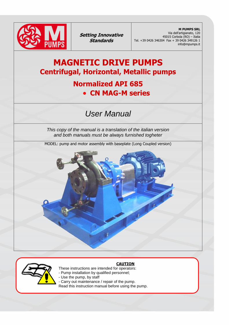
MAGNETIC DRIVE PUMPS Centrifugal, Horizontal, Metallic pumps
Normalized API 685
CN MAG-M series
User Manual
This copy of the manual is a translation of the italian version and both manuals must be always furnished togheter
MODEL: pump and motor assembly with baseplate (Long Coupled version)
CAUTION These instructions are intended for operators: - Pump installation by qualified personnel; - Use the pump, by staff - Carry out maintenance / repair of the pump. Read this instruction manual before using the pump.
Pag. 2/36 ISM0027 Instruction Manual of series CN MAG-M API685 – Rev.03
This INSTRUCTION MANUAL is intended to guide those responsible for the installation, operation and maintenance of M PUMPS CN MAG-M API685 series seal-less magnetic drive pumps. Please read it carefully, before you install and operate your M PUMPS pump. Useful information can also be obtained from: - Hydraulic Institute Standards (USA) regarding pump installation.
ISM0027 Instruction Manual of series CN MAG-M API685 – Rev.03 Pag. 3/36
CONTENTS GENERAL WARNINGS AND SAFETY ..................................................................................................................................... 4
Symbols used in the manual .......................................................................................................................................................... 4 WARRANTY ......................................................................................................................................................................... 4 NAMEPLATE ......................................................................................................................................................................... 5 PUMP DESCRIPTION AND OPERATING PRINCIPLE OF CENTRIFUGAL PUMPS ................................................................... 7
Applications .................................................................................................................................................................................. 7 TECHNICAL DATA ................................................................................................................................................................ 7 ALLOWABLE NOZZLE LOADS ............................................................................................................................................... 8 NOISE AND VIBRATION .................................................................................................................................................... 10 RADIATION IONISING ...................................................................................................................................................... 10 CHECKS TO PUMP DELIVERY, STORAGE............................................................................................................................ 10 SHIPPING AND HANDLING ............................................................................................................................................... 10 ASSEMBLY, INSTALLATION, CONNECTIONS, COMMISSIONING AND SETTING................................................................ 11
Assembly ................................................................................................................................................................................... 11 Connection of the pump to suction and discharge pipes ................................................................................................................ 11 Checks for the proper operation .................................................................................................................................................. 12 Commissioning and operator training ........................................................................................................................................... 12 Self-priming pumps and non self-priming pumps .......................................................................................................................... 13 Coupling of the pump to the motor .............................................................................................................................................. 13 Features and installation of pump and motor assembly ................................................................................................................. 13 Alignment of the coupling ........................................................................................................................................................... 14 Alignment tolerances and coupling .............................................................................................................................................. 14
INTENDED USE OF THE PUMP. IMPROPER USE. DESCRIPTION OF FUNCTIONING.PERSONAL PROTECTIVE EQUIPMENT DURING USE. ..................................................................................................................................................................... 14
Intended use of the pump ........................................................................................................................................................... 14 Instructions for proper use reasonably foreseeable ....................................................................................................................... 14 Not permitted use ....................................................................................................................................................................... 15
RESIDUAL RISKS AND PROTECTION MEASURES TO BE TAKEN ........................................................................................ 15 Description of the residual risks that remain ................................................................................................................................. 15 Protection measures to be taken by the user and instructions ....................................................................................................... 15 Personal protective equipment to wear ........................................................................................................................................ 16
OPERATIONAL LIMITS, DESCRIPTION OF HAZARDS NOT EXCLUDED FROM THE SECURITY MEASURES TAKEN ............ 16 Safety information present on the pump ...................................................................................................................................... 16
INSTRUCTIONS AND PROCEDURES FOR THE TRAINING OF THE PERSONNEL AND FOR EMERGENCIES ......................... 17 Recovery mode .......................................................................................................................................................................... 17 Fire-fighting equipment to be used: ............................................................................................................................................. 17 Emission / dispersion of harmful substances ................................................................................................................................. 17
MALFUNCTIONING, FAILURE, BREAKDOWN, ACCIDENT. MOST FREQUENT PROBLEMS: CAUSES AND REMEDIES .......... 17 Malfunctioning and Failure .......................................................................................................................................................... 17 Breakdown ................................................................................................................................................................................. 17 Accident ..................................................................................................................................................................................... 18 Most frequent drawbacks: problems, causes, remedies, residual risks ............................................................................................ 18
PERIODIC AND EXTRAORDINARY MAINTENANCE ............................................................................................................ 20 Cleaning components and magnet ............................................................................................................................................... 20 Periodic preventive maintenance ................................................................................................................................................. 21 Emptying of the fluid contained in the pump ................................................................................................................................ 21 Draining the oil contained in the pump ........................................................................................................................................ 22 Extraordinary maintenance .......................................................................................................................................................... 22
REPAIR AND PARTS REPLACEMENT ................................................................................................................................ 22 The periodic maintenance specified in the“ PERIODIC AND EXTRAORDINARY MAINTENANCE” ........................................................ 22 Pump disassembling ................................................................................................................................................................... 22 Pump reassembling .................................................................................................................................................................... 23
DECOMMISSIONING, DISMANTLING AND DISPOSAL OF MATERIALS ............................................................................. 27 Decommissioning ........................................................................................................................................................................ 27 Demolition and dismantling ......................................................................................................................................................... 27
EXPLODED VIEW PART LIST ............................................................................................................................................. 27 NOTES ............................................................................................................................................................................... 28 APPENDIX A – Register of maintenance and periodic checks of the pump ....................................................................... 29 APPENDIX B – Startup check list....................................................................................................................................... 30
Pag. 4/36 ISM0027 Instruction Manual of series CN MAG-M API685 – Rev.03
GENERAL WARNINGS AND SAFETY
This manual was prepared by M PUMPS pump to provide the buyer all necessary information for its proper use and regular maintenance. In this manual is also contained the manual of the electric motor when the pump is
supplied with this. For safety and hygiene of the workplace and to ensure a fair and sustainable use of the pump, the manual
should be kept for any consultation.
As part of the pump, this manual must go with it. For any given non-deductible or not included in this manual is recommended that you contact M PUMPS.
Do not use the pump before you have read and assimilated all safety rules and instructions in this
manual. In case of damage or loss of the manual, ask for a copy to M PUMPS promptly.
The failure to follow instructions in this manual, exempt M PUMPS from any liability.
The pump and the instructions are intended for operators who make professional use and should be used by qualified personnel adequately trained, aware of uses, operation and risk that the pump generates during its use,
the user with experience is the best form of qualification.
M PUMPS reserves at any time the right to make changes deemed necessary to improve the pump, taking care to
update this manual as soon as possible. This reflects the state of the art at the marketing pump. In case of transfer of the pump, the user is encouraged to report to M PUMPS the address of the new owner to facilitate the
transmission of any additions to the manual to the new user. M PUMPS reserves all rights to this manual, no total or partial reproduction is allowed without written permission.
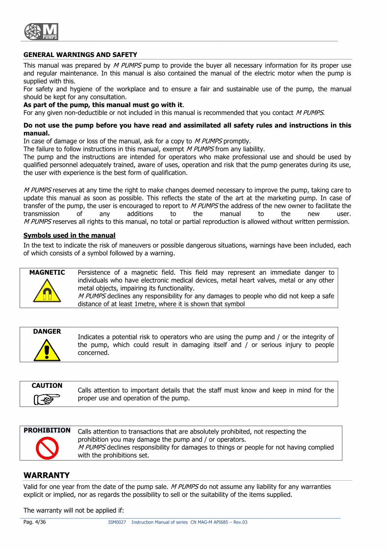
Symbols used in the manual
In the text to indicate the risk of maneuvers or possible dangerous situations, warnings have been included, each of which consists of a symbol followed by a warning.
MAGNETIC Persistence of a magnetic field. This field may represent an immediate danger to individuals who have electronic medical devices, metal heart valves, metal or any other
metal objects, impairing its functionality. M PUMPS declines any responsibility for any damages to people who did not keep a safe
distance of at least 1metre, where it is shown that symbol
DANGER Indicates a potential risk to operators who are using the pump and / or the integrity of the pump, which could result in damaging itself and / or serious injury to people
concerned.
CAUTION Calls attention to important details that the staff must know and keep in mind for the proper use and operation of the pump.
PROHIBITION Calls attention to transactions that are absolutely prohibited, not respecting the
prohibition you may damage the pump and / or operators. M PUMPS declines responsibility for damages to things or people for not having complied
with the prohibitions set.
WARRANTY
Valid for one year from the date of the pump sale. M PUMPS do not assume any liability for any warranties
explicit or implied, nor as regards the possibility to sell or the suitability of the items supplied.
The warranty will not be applied if:
ISM0027 Instruction Manual of series CN MAG-M API685 – Rev.03 Pag. 5/36
the repair and / or maintenance was not carried out strictly in accordance with the instructions;
the pump has not been installed and put into service as instructed;
the repairs were not made by staff M PUMPS or were made without consulting M PUMPS;
spare parts are not original were used;
lubricants were used different from those recommended;
the parts supplied were not used according to their nature and / or destination;
the parts supplied were used carelessly, negligently, improperly;
the parts supplied were damaged due to external circumstances.
All wear parts are excluded from warranty.
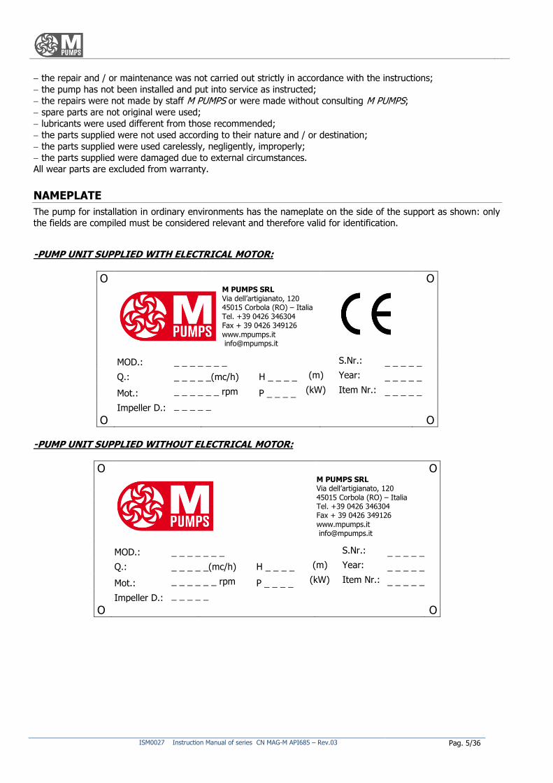
NAMEPLATE
The pump for installation in ordinary environments has the nameplate on the side of the support as shown: only
the fields are compiled must be considered relevant and therefore valid for identification.
-PUMP UNIT SUPPLIED WITH ELECTRICAL MOTOR:
O O
M PUMPS SRL Via dell’artigianato, 120 45015 Corbola (RO) – Italia Tel. +39 0426 346304 Fax + 39 0426 349126 www.mpumps.it [email protected]
MOD.: _ _ _ _ _ _ _ S.Nr.: _ _ _ _ _
Q.: _ _ _ _ _(mc/h) H _ _ _ _ (m) Year: _ _ _ _ _
Mot.: _ _ _ _ _ _ rpm P _ _ _ _ (kW) Item Nr.: _ _ _ _ _
Impeller D.: _ _ _ _ _
O O
-PUMP UNIT SUPPLIED WITHOUT ELECTRICAL MOTOR:
O O
M PUMPS SRL Via dell’artigianato, 120 45015 Corbola (RO) – Italia Tel. +39 0426 346304 Fax + 39 0426 349126 www.mpumps.it [email protected]
MOD.: _ _ _ _ _ _ _ S.Nr.: _ _ _ _ _
Q.: _ _ _ _ _(mc/h) H _ _ _ _ (m) Year: _ _ _ _ _
Mot.: _ _ _ _ _ _ rpm P _ _ _ _ (kW) Item Nr.: _ _ _ _ _
Impeller D.: _ _ _ _ _
O O
Pag. 6/36 ISM0027 Instruction Manual of series CN MAG-M API685 – Rev.03
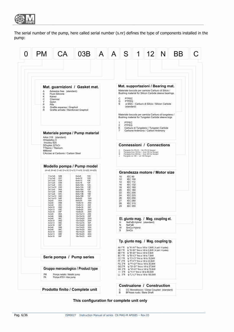
The serial number of the pump, here called serial number (s.nr) defines the type of components installed in the pump:
ISM0027 Instruction Manual of series CN MAG-M API685 – Rev.03 Pag. 7/36
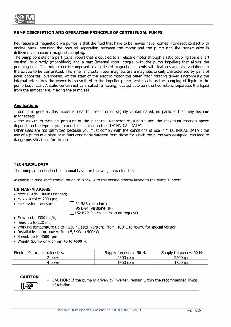
PUMP DESCRIPTION AND OPERATING PRINCIPLE OF CENTRIFUGAL PUMPS
Key feature of magnetic drive pumps is that the fluid that have to be moved never comes into direct contact with engine parts, ensuring the physical separation between the motor and the pump and the transmission is
delivered via a coaxial magnetic coupling. The pump consists of a part (outer rotor) that is coupled to an electric motor through elastic coupling (bare shaft
version) or directly (monoblock) and a part (internal rotor integral with the pump impeller) that allows the pumping fluid. The outer rotor is composed of a series of magnetic elements with features and size variations to
the torque to be transmitted. The inner and outer rotor magnets are a magnetic circuit, characterized by pairs of
polar opposites, overlooked. At the start of the electric motor the outer rotor rotating drives sincronously the internal rotor, thus the power is transmitted to the impeller pump, which acts as the pumping of liquid in the
pump body itself. A static containmet can, called rer casing, located between the two rotors, separates the liquid from the atmosphere, making the pump seal.
Applications
pumps in general, this model is ideal for clean liquids slightly contaminated, no particles that may become
magnetized;
the maximum working pressure of the plant,the temperature suitable and the maximum rotation speed
depends on the type of pump and it is specified in the "TECHNICAL DATA". Other uses are not permitted because you must comply with the conditions of use in "TECHNICAL DATA": the
use of a pump in a plant or in fluid conditions different from those for which the pump was designed, can lead to dangerous situations for the user.
TECHNICAL DATA
The pumps described in this manual have the following characteristics:
Available in bare shaft configuration or block, with the engine directly keyed to the pump support.
CN MAG-M API685
Nozzle: ANSI 300lbs flanged;
Max viscosity: 200 cps;
Max system pressure: 52 BAR (standard)
95 BAR (versione HP) 152 BAR (special version on request)
Flow up to 4000 mc/h;
Head up to 220 m;
Working temperature up to +250 °C (std. Version), from -100°C to 450°C for special version
Installable motor power: from 5,5KW to 500KW;
Speed: up to 3500 rpm;
Weight (pump only): from 46 to 4500 kg;
Electric Motor characteristics: Supply frequency: 50 Hz Supply frequency: 60 Hz
2 poles 2900 rpm 3500 rpm
4 poles 1450 rpm 1750 rpm
CAUTION CAUTION: If the pump is driven by inverter, remain within the recommended limits
of rotation
Pag. 8/36 ISM0027 Instruction Manual of series CN MAG-M API685 – Rev.03
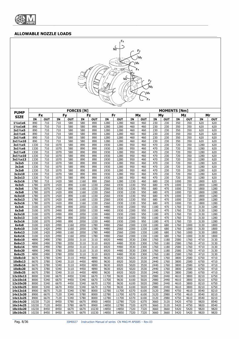
ALLOWABLE NOZZLE LOADS
PUMP SIZE
FORCES [N] MOMENTS [Nm]
Fx Fy Fz Fr Mx My Mz Mr IN OUT IN OUT IN OUT IN OUT IN OUT IN OUT IN OUT IN OUT
1½x1x6 890 710 710 580 580 890 1280 1280 460 460 230 230 350 350 620 620
1½x1x8 890 710 710 580 580 890 1280 1280 460 460 230 230 350 350 620 620
2x1½x5 890 710 710 580 580 890 1280 1280 460 460 230 230 350 350 620 620
2x1½x6 890 710 710 580 580 890 1280 1280 460 460 230 230 350 350 620 620
2x1½x8 890 710 710 580 580 890 1280 1280 460 460 230 230 350 350 620 620
2x1½x10 890 710 710 580 580 890 1280 1280 460 460 230 230 350 350 620 620
3x1½x5 1330 710 1070 580 890 890 1930 1280 950 460 470 230 720 350 1280 620
3x1½x6 1330 710 1070 580 890 890 1930 1280 950 460 470 230 720 350 1280 620
3x1½x8 1330 710 1070 580 890 890 1930 1280 950 460 470 230 720 350 1280 620
3x1½x10 1330 710 1070 580 890 890 1930 1280 950 460 470 230 720 350 1280 620
3x1½x13 1330 710 1070 580 890 890 1930 1280 950 460 470 230 720 350 1280 620
3x2x5 1330 710 1070 580 890 890 1930 1280 950 460 470 230 720 350 1280 620
3x2x6 1330 710 1070 580 890 890 1930 1280 950 460 470 230 720 350 1280 620
3x2x8 1330 710 1070 580 890 890 1930 1280 950 460 470 230 720 350 1280 620
3x2x10 1330 710 1070 580 890 890 1930 1280 950 460 470 230 720 350 1280 620
3x2x13 1330 710 1070 580 890 890 1930 1280 950 460 470 230 720 350 1280 620
4x2x16 1780 710 1420 580 1160 890 2560 1280 1330 460 680 230 1000 350 1800 620
4x3x5 1780 1070 1420 890 1160 1330 2560 1930 1330 950 680 470 1000 720 1800 1280
4x3x6 1780 1070 1420 890 1160 1330 2560 1930 1330 950 680 470 1000 720 1800 1280
4x3x8 1780 1070 1420 890 1160 1330 2560 1930 1330 950 680 470 1000 720 1800 1280
4x3x10 1780 1070 1420 890 1160 1330 2560 1930 1330 950 680 470 1000 720 1800 1280
4x3x13 1780 1070 1420 890 1160 1330 2560 1930 1330 950 680 470 1000 720 1800 1280
4x3x16 1780 1070 1420 890 1160 1330 2560 1930 1330 950 680 470 1000 720 1800 1280
6x3x6 3100 1070 2490 890 2050 1330 4480 1930 2300 950 1180 470 1760 720 3130 1280
6x3x8 3100 1070 2490 890 2050 1330 4480 1930 2300 950 1180 470 1760 720 3130 1280
6x3x10 3100 1070 2490 890 2050 1330 4480 1930 2300 950 1180 470 1760 720 3130 1280
6x3x13 3100 1070 2490 890 2050 1330 4480 1930 2300 950 1180 470 1760 720 3130 1280
6x3x16 3100 1070 2490 890 2050 1330 4480 1930 2300 950 1180 470 1760 720 3130 1280
6x4x8 3100 1420 2490 1160 2050 1780 4480 2560 2300 1330 1180 680 1760 1000 3130 1800
6x4x10 3100 1420 2490 1160 2050 1780 4480 2560 2300 1330 1180 680 1760 1000 3130 1800
6x4x13 3100 1420 2490 1160 2050 1780 4480 2560 2300 1330 1180 680 1760 1000 3130 1800
6x4x16 3100 1420 2490 1160 2050 1780 4480 2560 2300 1330 1180 680 1760 1000 3130 1800
8x6x10 4890 2490 3780 2050 3110 3110 6920 4480 3530 2300 1760 1180 2580 1760 4710 3130
8x6x13 4890 2490 3780 2050 3110 3110 6920 4480 3530 2300 1760 1180 2580 1760 4710 3130
8x6x16 4890 2490 3780 2050 3110 3110 6920 4480 3530 2300 1760 1180 2580 1760 4710 3130
8x6x20 4890 2490 3780 2050 3110 3110 6920 4480 3530 2300 1760 1180 2580 1760 4710 3130
8x6x25 4890 2490 3780 2050 3110 3110 6920 4480 3530 2300 1760 1180 2580 1760 4710 3130
10x8x10 6670 3780 5340 3110 4450 4890 9630 6920 5020 3530 2440 1760 3800 2580 6750 4710
10x8x13 6670 3780 5340 3110 4450 4890 9630 6920 5020 3530 2440 1760 3800 2580 6750 4710
10x8x16 6670 3780 5340 3110 4450 4890 9630 6920 5020 3530 2440 1760 3800 2580 6750 4710
10x8x20 6670 3780 5340 3110 4450 4890 9630 6920 5020 3530 2440 1760 3800 2580 6750 4710
10x8x25 6670 3780 5340 3110 4450 4890 9630 6920 5020 3530 2440 1760 3800 2580 6750 4710
12x10x13 8000 5340 6670 4450 5340 6670 11700 9630 6100 5020 2980 2440 4610 3800 8210 6750
12x10x16 8000 5340 6670 4450 5340 6670 11700 9630 6100 5020 2980 2440 4610 3800 8210 6750
12x10x20 8000 5340 6670 4450 5340 6670 11700 9630 6100 5020 2980 2440 4610 3800 8210 6750
12x10x25 8000 5340 6670 4450 5340 6670 11700 9630 6100 5020 2980 2440 4610 3800 8210 6750
14x12x16 8900 6670 7120 5340 5780 8000 12780 11700 6370 6100 3120 2980 4750 4610 8540 8210
14x12x20 8900 6670 7120 5340 5780 8000 12780 11700 6370 6100 3120 2980 4750 4610 8540 8210
14x12x25 8900 6670 7120 5340 5780 8000 12780 11700 6370 6100 3120 2980 4750 4610 8540 8210
16x14x20 10230 7120 8450 5780 6670 8900 14850 12780 7320 6370 3660 3120 5420 4750 9820 8540
16x14x25 10230 7120 8450 5780 6670 8900 14850 12780 7320 6370 3660 3120 5420 4750 9820 8540
18x16x20 10230 8450 8450 6670 6670 10230 14850 14850 7320 7320 3660 3660 5420 5420 9820 9820
18x16x25 10230 8450 8450 6670 6670 10230 14850 14850 7320 7320 3660 3660 5420 5420 9820 9820
ISM0027 Instruction Manual of series CN MAG-M API685 – Rev.03 Pag. 9/36
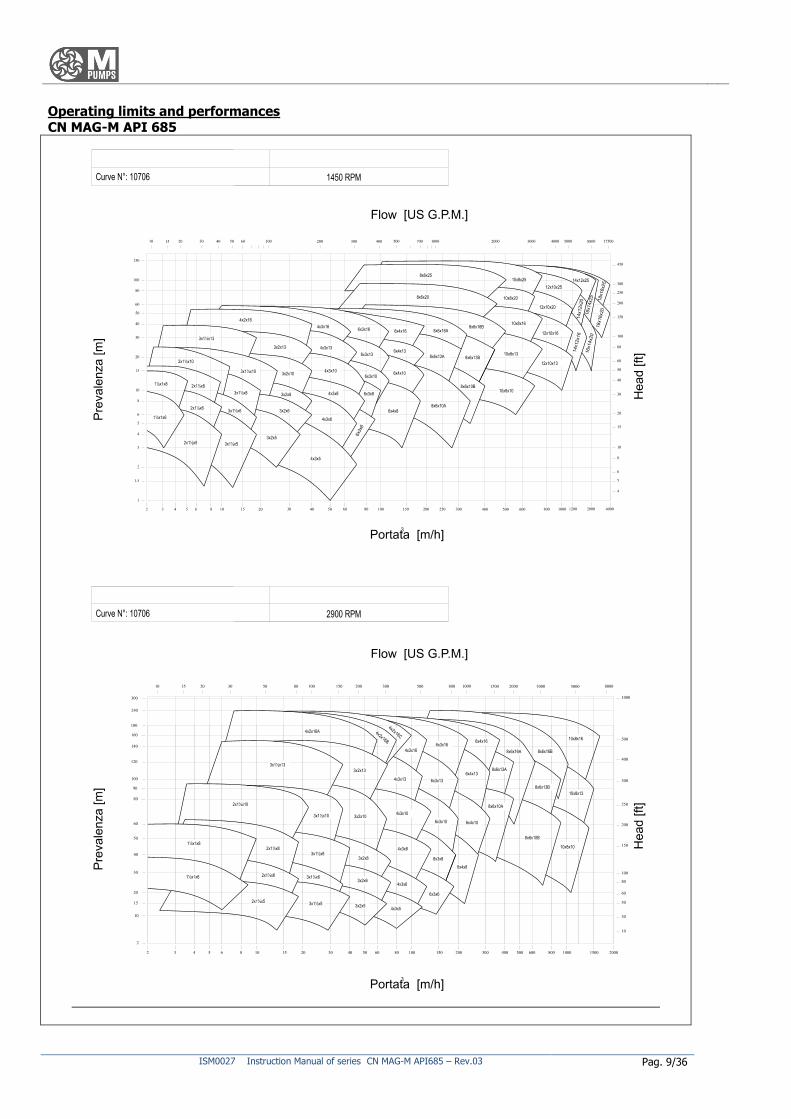
Operating limits and performances CN MAG-M API 685
Pag. 10/36 ISM0027 Instruction Manual of series CN MAG-M API685 – Rev.03
OVERALL DIMENSIONS See specific documentation provided with this manual.
NOISE AND VIBRATION
The pump noise depends primarily on the operating conditions. The operating condition of the pump during the measurements is: the coupling of the pump with the electric motor on the bench with pumping fluids.
The A-weighted sound pressure level to front and side of the pump is below 85 dB (A).
RADIATION IONISING
The pump does not emit any kind of ionising radiation that could endanger persons.
CHECKS TO PUMP DELIVERY, STORAGE
All M PUMPS pumps are tested before shipment and carefully packed for transport: at the reception of the pump make sure that the pump has not been damaged during the transport. If there are problems, contact
immediately the carrier and inform M PUMPS about what happened. So that the pump is preserved over time as best as possibile, we recommend storing it away from the sun, bad
weather and dust, if not immediately installed or used for long periods.
Stoppers closing the input and output connections of the fluid must not be removed until installation. If provided with electric motor, observe also the motor manufacturer’s storage formality.
The maximum allowable temperature range during storage, preservation and use must be between -15 e +40 °C with humidity between 10 e 90%.
SHIPPING AND HANDLING
You should carry out a precautionary check of the pump at the receiving to detect and report any damage in the
transport and handling operations. In case of breakages contact immediately M PUMPS.
The precautions to ensure the stability of the pump concern the possible slips and overturning caused by handling and transport, which must be prevented by setting the pump casing of the pump with ropes to the
vehicle frame. Pump and motor assembly cannot be moved manually due to its high weight.
To move a pump positioned on a pallet, enlarge as maximum as possible the forks and then operate.
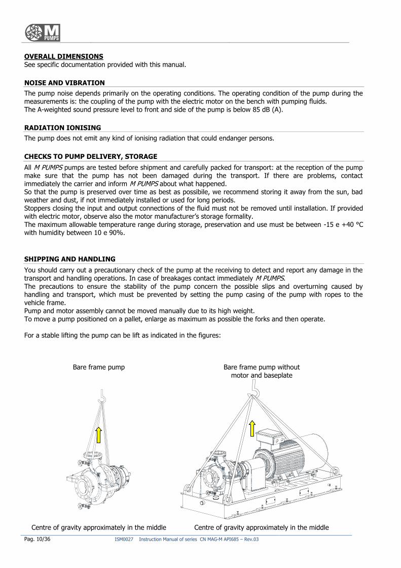
For a stable lifting the pump can be lift as indicated in the figures:
Bare frame pump Bare frame pump without
motor and baseplate
Centre of gravity approximately in the middle Centre of gravity approximately in the middle
ISM0027 Instruction Manual of series CN MAG-M API685 – Rev.03 Pag. 11/36
These operations must be performed by a trained staff who is informed of the risk of these proceedings.
PROHIBITION
It is forbidden to lift the pump using different lugs from the ones specially designed and
reported, as points of anchorage. You cannot lift a pump and motor assembly using the eye-bolt of the electric motor
only.
During the lifting the entire surrounding area is considered as a danger zone and must
be cleared by personnel not engaged in those operations.
It is indicated the possibility of transporting and handling the pump using the lugs designed for that use: you must ensure that chains and shackles are able to withstand the weight of the pump (as shown in "TECHNICAL
DATA").
ASSEMBLY, INSTALLATION, CONNECTIONS, COMMISSIONING AND SETTING
Assembly
Install the pump on a solid foundation as close as possible to the liquid to be pumped, below the level, in a
position to facilitate maintenance and inspection. Ensure that the pump doesn’t take rough shacks as this may damage the magnets of the internal and external
rotor or the silicon carbide bearings. Ensure that the heated air from other units does not affect the pump; the air temperature must not exceed
40 °C, for higher temperatures contact your distributor M PUMPS; ensure also the free circulation of air cooling of
at least ¼ the engine diameter, because either the pump or the motor should be able to dissipate the heat by natural air convection. Insufficient cooling could lead to high surface temperatures of the bearings seat, poor
lubrication and premature failure of bearings. Useful is the monitoring of the surface bearings’ temperature. It is always responsibility of the operator to keep low the temperature of the liquid so that not to superheat the
pump: in case of irregular pressure fluctuations and flow drop turn off the pump.
CAUTION Normally you should mount the pump horizontally. If mounted vertically or inclined,
the pump, or rather the suction flange shall be placed in the lowest point. Leave a
space of at least 50 cm between the pump and any walls or pipes. When pumping liquid can reach high temperatures: form 60 °C upwards you must
install protections to prevent contact with hot pump parts;
Connect to the ground the entire pump casing to prevent accumulation of static
electricity;
If the pumped liquid can be dangerous to people and environment, the user must take
precautions for a simple and quick block in case of leakage for breakage/ replacement/ pump maintenance.
Connection of the pump to suction and discharge pipes
For a proper assembly aimed at an optimal use of the pump, you must follow these requirements:
pipes must be supported and kept in line regardless of the pump, until its connections, so that not to
impose on it;
links must not be subjected to stresses during the job ;
the maximum permissible forces and moments on flanges shall not exceed those listed in “technical
data”; inlet pipes should be constructed with as few restrictions as possible in order to have the highest
available NPSH;
the length of pipes , particularly that of the inlet pipe must be minimized;
the pipe must be placed so that it is not possible the formation of air; if this is not possible, it should be
calculated the possibility of bleeding the air from the highest point ; during suction use full section valves only;
Pag. 12/36 ISM0027 Instruction Manual of series CN MAG-M API685 – Rev.03
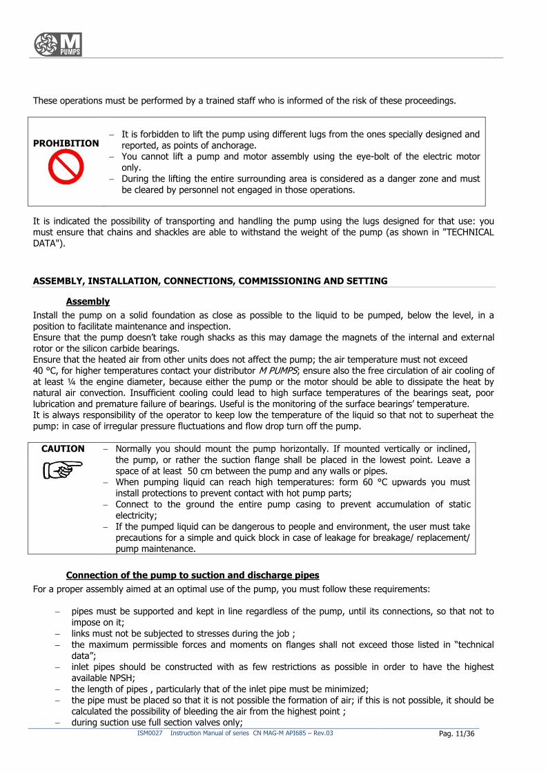
if the suction tube was larger than the suction flange, you will use an eccentric reduction, in order to prevent
formation of air and turbulence;
if there is a possibility that the maximum working pressure can be overcome, for example due to excessive suction pressure, you should take appropriate measures by including a safety valve in the pipe;
Avoid using quick-closing valves, because sudden changes of pressure cause water hammer very dangerous for
the pump and the pipes; Before installing the pump, make sure the suction line is clean and/or provided with a filter to protect the
impeller and the stationary bearings from damages incurred by slag, or other foreign particles , especially when you start the installation for the first time.
Electrical connections:
DANGER
The pump is provided with or without electric motor: only qualified personnel
should carry out mechanical connection of the pump to the motor (for the model without motor) and the electrical connections of the motor to the electrical system. Please read
carefully the instructions of the manufacturer of the motor or the manual before you complete the installation.
Make sure that the motor doesn’t start during maintenance jobs.
Checks for the proper operation
We recommend installing a pressure gauge on both inlet and outlet pipes to allow the operator to easily control the proper pump functioning in relation to the required operating point: in case of cavitation or other
malfunctions, there will be obvious pressure fluctuations. Check the differential pressure of the pump between the suction and discharge connections to verify that it works
in the point of work provided. Check that the absolute pressure at suction is not so low to cause the cavitation.
CAUTION The absolute pressure at pump suction (m) must be at least 0,5 to 1 m, the vapour
pressure of the pumped liquid, in order to avoid cavitation.
Cavitation should always be avoided as it is very dangerous for the structure of the pump. Do not dry run the pump!
Commissioning and operator training
Fully open the inlet valve and fill the pump and suction line;
Ensure there are no obstacles to the free rotation of the pump impeller.
ISM0027 Instruction Manual of series CN MAG-M API685 – Rev.03 Pag. 13/36
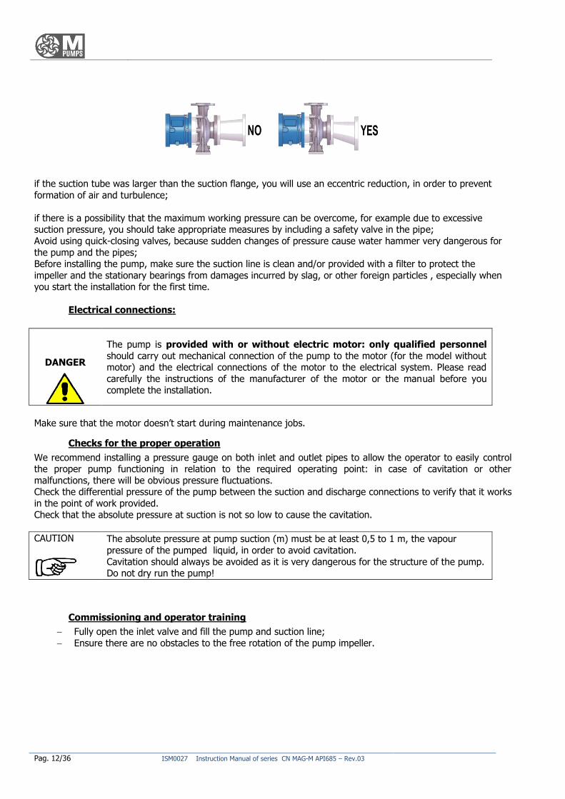
The M PUMPS series CN MAG-M API685 are not reversible so the rotation cannot be reversed.
The proper direction is counter clockwise. If you put in front of the pump casing, an arrow
indicates the correct direction of rotation; to reverse
the direction of rotation may cause damages to the pump.
To control the direction of rotation, give and immediately remove voltage, then observe the
direction of rotation.
ROTATION SENSE:
Make sure that rotating parts, such as flexible coupling or other related organs, are always protected when the
pump is running.
Operators using the pump must have read this manual in the sections committed to the functioning, use and maintenance, as well as being qualified to fully understand the features and to be able to identify the problems of
the pump.
By carrying out the functions mentioned in the previous section and all controls listed in the register maintenance, the pump is ready for use.
Self-priming pumps and non self-priming pumps
CN MAG-M API685 pumps are self-priming: Make sure the pump is always filled with the pumping liquid to maintain the self-priming feature. Use a back flow check valve to stop reverse flow when operating with suction
lift, dry run should be avoided.
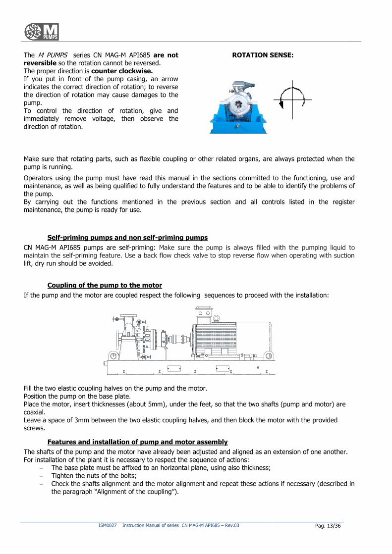
Coupling of the pump to the motor
If the pump and the motor are coupled respect the following sequences to proceed with the installation:
Fill the two elastic coupling halves on the pump and the motor.
Position the pump on the base plate. Place the motor, insert thicknesses (about 5mm), under the feet, so that the two shafts (pump and motor) are
coaxial.
Leave a space of 3mm between the two elastic coupling halves, and then block the motor with the provided screws.
Features and installation of pump and motor assembly
The shafts of the pump and the motor have already been adjusted and aligned as an extension of one another.
For installation of the plant it is necessary to respect the sequence of actions: The base plate must be affixed to an horizontal plane, using also thickness;
Tighten the nuts of the bolts;
Check the shafts alignment and the motor alignment and repeat these actions if necessary (described in
the paragraph “Alignment of the coupling”).
Pag. 14/36 ISM0027 Instruction Manual of series CN MAG-M API685 – Rev.03
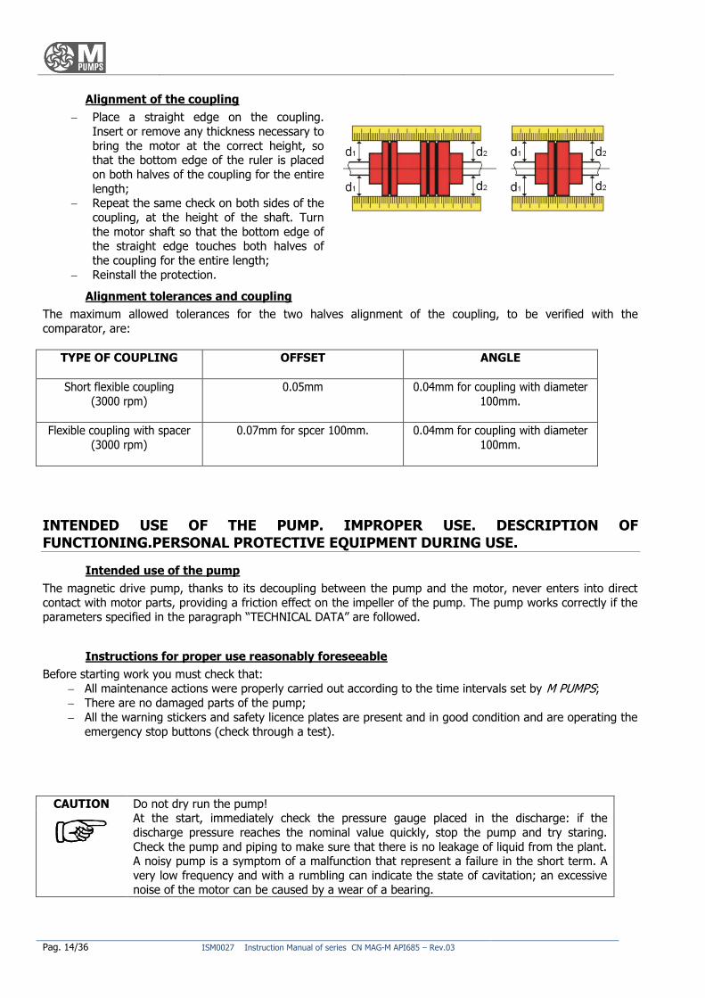
Alignment of the coupling
Place a straight edge on the coupling.
Insert or remove any thickness necessary to
bring the motor at the correct height, so that the bottom edge of the ruler is placed
on both halves of the coupling for the entire
length; Repeat the same check on both sides of the
coupling, at the height of the shaft. Turn
the motor shaft so that the bottom edge of the straight edge touches both halves of
the coupling for the entire length;
Reinstall the protection.
Alignment tolerances and coupling
The maximum allowed tolerances for the two halves alignment of the coupling, to be verified with the
comparator, are:
TYPE OF COUPLING OFFSET ANGLE
Short flexible coupling
(3000 rpm)
0.05mm 0.04mm for coupling with diameter
100mm.
Flexible coupling with spacer
(3000 rpm)
0.07mm for spcer 100mm. 0.04mm for coupling with diameter
100mm.
INTENDED USE OF THE PUMP. IMPROPER USE. DESCRIPTION OF
FUNCTIONING.PERSONAL PROTECTIVE EQUIPMENT DURING USE.
Intended use of the pump
The magnetic drive pump, thanks to its decoupling between the pump and the motor, never enters into direct
contact with motor parts, providing a friction effect on the impeller of the pump. The pump works correctly if the parameters specified in the paragraph “TECHNICAL DATA” are followed.
Instructions for proper use reasonably foreseeable
Before starting work you must check that:
All maintenance actions were properly carried out according to the time intervals set by M PUMPS;
There are no damaged parts of the pump;
All the warning stickers and safety licence plates are present and in good condition and are operating the
emergency stop buttons (check through a test).
CAUTION Do not dry run the pump! At the start, immediately check the pressure gauge placed in the discharge: if the
discharge pressure reaches the nominal value quickly, stop the pump and try staring.
Check the pump and piping to make sure that there is no leakage of liquid from the plant. A noisy pump is a symptom of a malfunction that represent a failure in the short term. A
very low frequency and with a rumbling can indicate the state of cavitation; an excessive noise of the motor can be caused by a wear of a bearing.
ISM0027 Instruction Manual of series CN MAG-M API685 – Rev.03 Pag. 15/36
Not permitted use
While maintaining the conditions of use indicated in the paragraph “TECHNICAL DATA”, the ways in which the
pump should not be used are given here. To avoid damaging the pump, it is forbidden to use it in the following conditions:
PROHIBITION
Start the pump dry: the pump casing must be full of liquid.
Run the pump dry for more than 1 minute;
Mare the pump work with inlet valve and /or outlet closed: the heat generated by the
impeller, by magnetic coupling and bearings will boil the liquid, which will cause pump
cavitation/vibration, the impeller damaging and the bearings collapse;
The pump flow should never be adjusted by the valve located in the suction pipe,
which must be kept fully open, start and or make the pump work if there are losses; Start the pump if there are losses;
Change working condition of the pump without having consulted the M PUMPS
technical office;
loosen the pump connections while under pressure;
try to clean the pump while it is running;
run the pump in the opposite direction to that shown in the pump casing;
run the pump over nominal temperature and pressure;
pumping liquids containing ferromagnetic particles of any size, or substances that can
attack chemically or erode the inside of the pump; remove guards and shelters while the pump is running;
act on electrical parts installed without first removing the tension, not to alter the
safety devices installed, do not activate repeatedly the command buttons.
DANGER It is incorrect any use of the pump other than that mentioned in the paragraph “Instructions for a proper use reasonably foreseeable”.
M PUMPS disclaims any liability damages to things and people related to uses for which the pump was not specifically designed and constructed.
Also the ways in which certain situations of danger might present as a result of improper use, are prohibited.
RESIDUAL RISKS AND PROTECTION MEASURES TO BE TAKEN
Description of the residual risks that remain
Despite adopted measures incorporated in the pump, the main dangers associated with the use of the pump and the solutions identified are the followings:
Danger of sketches projection of process fluid that can be corrosive or burning, as a result of improper installation and sudden ruptures of the pump casing and hydraulic lines;
Danger of cuts to the hands due to the presence of smears on the pump casing; Explosion of the pump is due to a formation of explosive mixture inside the pump casing as a result of an
improper use.
Protection measures to be taken by the user and instructions
PROHIBITION
It is absolutely forbidden to the user to tamper with safety devices. Before using the pump check the proper couplings mechanical protection. Any tampering nullifies the
warranty and liability of M PUMPS towards the pump users.
Only maintenance personnel can perform maintenance operation affecting safety devices.
Pag. 16/36 ISM0027 Instruction Manual of series CN MAG-M API685 – Rev.03
Personal protective equipment to wear
Protection measures that have to be taken during this phase are adopting antacid and antistatic coverall,
chemical-resistant glasses, gloves to protect from mechanical and chemical agents and safety shoes. Avoid the use of accessories (necklaces, bracelets, etc.) and clothes unshackled; torn or dangling that could get
entangled in parts of the structure.
OPERATIONAL LIMITS, DESCRIPTION OF HAZARDS NOT EXCLUDED FROM THE SECURITY MEASURES TAKEN
Dangers that have not been reduced/ eliminated with the security measures adopted on the pump can be
reduced/eliminated if operators apply measures on management as a result of having to:
Keep all the safety warnings of and all plaques and labels intact and replace them when necessary,
periodically checking their good condition; Don’t employ substances which may affect the physical ability or the mental faculty (alcoholic
beverages, medicines, drugs, etc);
Don’t use without permission spare parts not identical to the originals or components not approved by
M PUMPS; Don’t perform any modification or structural intervention without the approval of M PUMPS;
After shocks accidentally suffered by the pump, check the pump integrity and perform a check to
M PUMPS;
After a long period of pump detention check the pump integrity and functionality of stakeholders to
wear. If necessary perform the replacement with identical spare parts to the originals.
CAUTION Each of the misuse or negligence listed here causes:
immediate cancellation of M PUMPS assistance.
cancellation of M PUMPS responsibility for damage to property, animals or people.
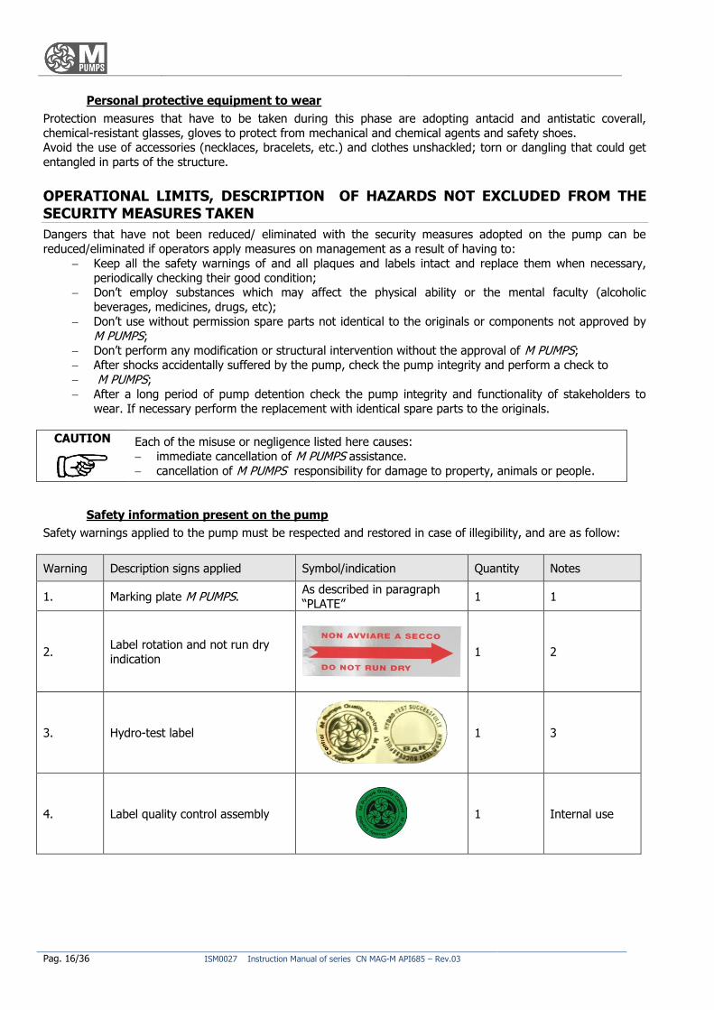
Safety information present on the pump
Safety warnings applied to the pump must be respected and restored in case of illegibility, and are as follow:
Warning Description signs applied Symbol/indication Quantity Notes
1. Marking plate M PUMPS. As described in paragraph
“PLATE” 1 1
2. Label rotation and not run dry
indication
1 2
3. Hydro-test label
1 3
4. Label quality control assembly
1 Internal use
ISM0027 Instruction Manual of series CN MAG-M API685 – Rev.03 Pag. 17/36
INSTRUCTIONS AND PROCEDURES FOR THE TRAINING OF THE PERSONNEL AND
FOR EMERGENCIES
Operators responsible for the various life stages of the pump must be:
- for assemblers: staff formed and trained on good practices for handling of goods with the use of tools and lifting equipment;
- for installers of pipes and electrical connections: qualified and trained staff to operate on electrical plants, staff
with experience in hydraulic installations; -f or users: professional staff trained in the instruction for use of this pump.
In case of emergency: - alert who is close to the situation of danger, even waving his arms;
- stop the pump by pressing the nearest emergency stop button;
Recovery mode
To return to normal operating conditions, you must delete all the causes that have generated the emergency, possibly repairing or replacing the components that caused the failure.
CAUTION After the intervention of security devices, you must find the cause of action before continuing operations.
Fire-fighting equipment to be used:
In case of fire involving the pump, you can use water or foam liquid only after removing the voltage, or a powder type fire extinguisher with extinguishing agent. Do not use CO2 as being launched at -79 ° C may react violently
with the hot parts.
Emission / dispersion of harmful substances
The fluid in the plant might be released in the atmosphere following an intervention or the pump break.
MALFUNCTIONING, FAILURE, BREAKDOWN, ACCIDENT. MOST FREQUENT
PROBLEMS: CAUSES AND REMEDIES
There aren’t pump details which provide such cases of malfunctioning as to restrict or make its use dangerous. In paragraph “Most frequent drawbacks: causes and remedy” is discussed with more details in this section.
Malfunctioning and Failure
In case of failure of mechanical parts you must immediately restore the original terms of security by replacing or
repairing the parts that have deficiencies.
In case of failure of the pump, proceed as follows: - Turn the motor off;
- close the inlet and outlet valves; - find the cause of the failure by checking the section “ Most frequent drawbacks: problems, causes,
remedies, residual risks".
The failure of a pumping plant can be attributed to: - a pump failure;
- a failure or defect in the pipe; a failure due to an installation or a start not correctly executed;
wrong choice of pump.
Breakdown
In the event of failure of pump alert verbally the staff present in the nearness of the damage that is verifying.
Pag. 18/36 ISM0027 Instruction Manual of series CN MAG-M API685 – Rev.03
Accident
In case of accident, you must report the emergency to the plant responsible for the installation, in order to
secure the plant to reach with the emergency team the place where the accident happened.
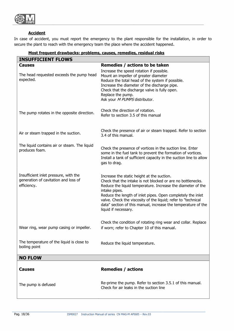
Most frequent drawbacks: problems, causes, remedies, residual risks
INSUFFICIENT FLOWS Causes Remedies / actions to be taken The head requested exceeds the pump head
expected.
Increase the speed rotation if possible.
Mount an impeller of greater diameter Reduce the total head of the system if possible.
Increase the diameter of the discharge pipe.
Check that the discharge valve is fully open. Replace the pump.
Ask your M PUMPS distributor.
The pump rotates in the opposite direction. Check the direction of rotation.
Refer to section 3.5 of this manual
Air or steam trapped in the suction. Check the presence of air or steam trapped. Refer to section 3.4 of this manual.
The liquid contains air or steam. The liquid
produces foam. Check the presence of vortices in the suction line. Enter some in the fuel tank to prevent the formation of vortices.
Install a tank of sufficient capacity in the suction line to allow
gas to drag.
Insufficient inlet pressure, with the
generation of cavitation and loss of
efficiency.
Increase the static height at the suction. Check that the intake is not blocked or are no bottlenecks. Reduce the liquid temperature. Increase the diameter of the
intake pipes.
Reduce the length of inlet pipes. Open completely the inlet valve. Check the viscosity of the liquid; refer to "technical
data" section of this manual, increase the temperature of the liquid if necessary.
Wear ring, wear pump casing or impeller.
Check the condition of rotating ring wear and collar. Replace
if worn; refer to Chapter 10 of this manual.
The temperature of the liquid is close to boiling point
Reduce the liquid temperature.
NO FLOW
Causes
Remedies / actions
The pump is defused
Re-prime the pump. Refer to section 3.5.1 of this manual.
Check for air leaks in the suction line
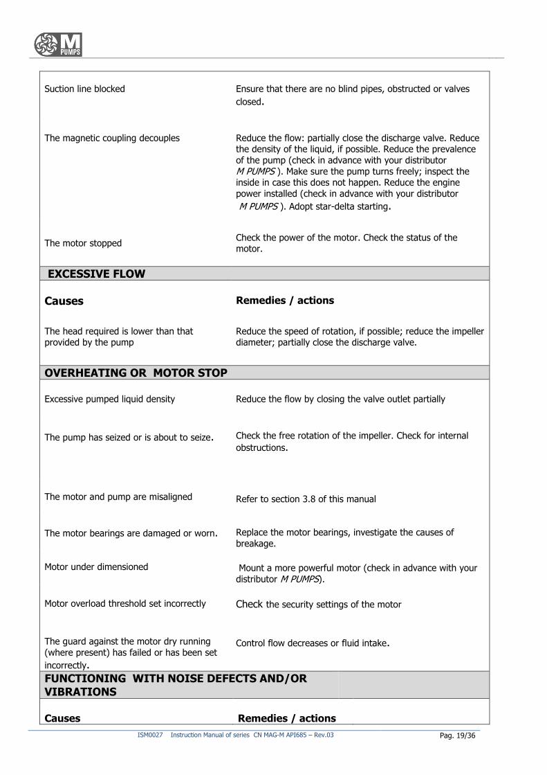
ISM0027 Instruction Manual of series CN MAG-M API685 – Rev.03 Pag. 19/36
Suction line blocked
Ensure that there are no blind pipes, obstructed or valves
closed.
The magnetic coupling decouples
Reduce the flow: partially close the discharge valve. Reduce the density of the liquid, if possible. Reduce the prevalence
of the pump (check in advance with your distributor
M PUMPS ). Make sure the pump turns freely; inspect the inside in case this does not happen. Reduce the engine
power installed (check in advance with your distributor
M PUMPS ). Adopt star-delta starting.
The motor stopped Check the power of the motor. Check the status of the motor.
EXCESSIVE FLOW
Causes
Remedies / actions
The head required is lower than that provided by the pump
Reduce the speed of rotation, if possible; reduce the impeller diameter; partially close the discharge valve.
OVERHEATING OR MOTOR STOP
Excessive pumped liquid density
Reduce the flow by closing the valve outlet partially
The pump has seized or is about to seize.
Check the free rotation of the impeller. Check for internal
obstructions.
The motor and pump are misaligned
Refer to section 3.8 of this manual
The motor bearings are damaged or worn.
Replace the motor bearings, investigate the causes of
breakage.
Motor under dimensioned Mount a more powerful motor (check in advance with your
distributor M PUMPS).
Motor overload threshold set incorrectly
Check the security settings of the motor
The guard against the motor dry running
(where present) has failed or has been set
incorrectly.
Control flow decreases or fluid intake.
FUNCTIONING WITH NOISE DEFECTS AND/OR VIBRATIONS
Causes
Remedies / actions
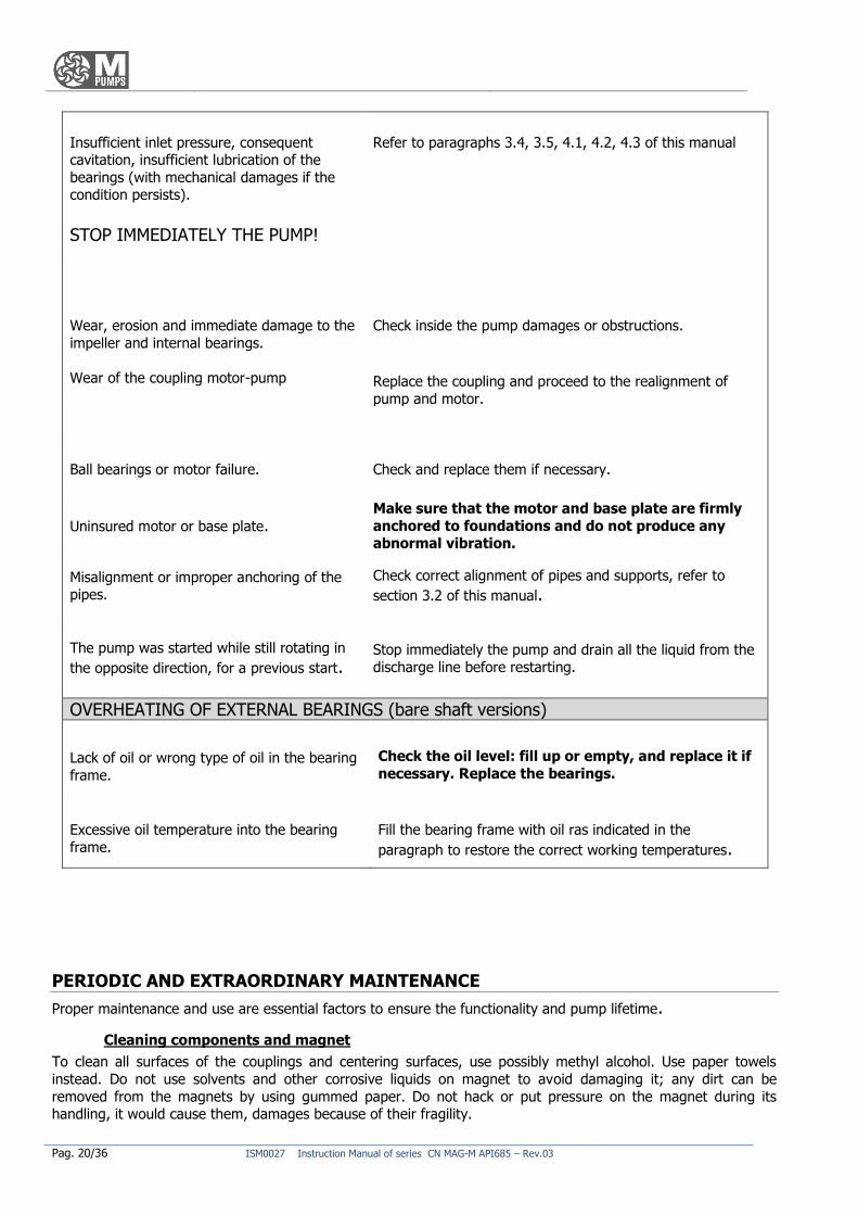
Pag. 20/36 ISM0027 Instruction Manual of series CN MAG-M API685 – Rev.03
Insufficient inlet pressure, consequent cavitation, insufficient lubrication of the
bearings (with mechanical damages if the condition persists).
STOP IMMEDIATELY THE PUMP!
Refer to paragraphs 3.4, 3.5, 4.1, 4.2, 4.3 of this manual
Wear, erosion and immediate damage to the
impeller and internal bearings.
Check inside the pump damages or obstructions.
Wear of the coupling motor-pump Replace the coupling and proceed to the realignment of
pump and motor.
Ball bearings or motor failure. Check and replace them if necessary.
Uninsured motor or base plate. Make sure that the motor and base plate are firmly
anchored to foundations and do not produce any abnormal vibration.
Misalignment or improper anchoring of the pipes.
Check correct alignment of pipes and supports, refer to
section 3.2 of this manual.
The pump was started while still rotating in
the opposite direction, for a previous start.
Stop immediately the pump and drain all the liquid from the
discharge line before restarting.
OVERHEATING OF EXTERNAL BEARINGS (bare shaft versions)
Lack of oil or wrong type of oil in the bearing
frame.
Check the oil level: fill up or empty, and replace it if
necessary. Replace the bearings.
Excessive oil temperature into the bearing
frame.
Fill the bearing frame with oil ras indicated in the
paragraph to restore the correct working temperatures.
PERIODIC AND EXTRAORDINARY MAINTENANCE
Proper maintenance and use are essential factors to ensure the functionality and pump lifetime.
Cleaning components and magnet
To clean all surfaces of the couplings and centering surfaces, use possibly methyl alcohol. Use paper towels
instead. Do not use solvents and other corrosive liquids on magnet to avoid damaging it; any dirt can be
removed from the magnets by using gummed paper. Do not hack or put pressure on the magnet during its handling, it would cause them, damages because of their fragility.
ISM0027 Instruction Manual of series CN MAG-M API685 – Rev.03 Pag. 21/36
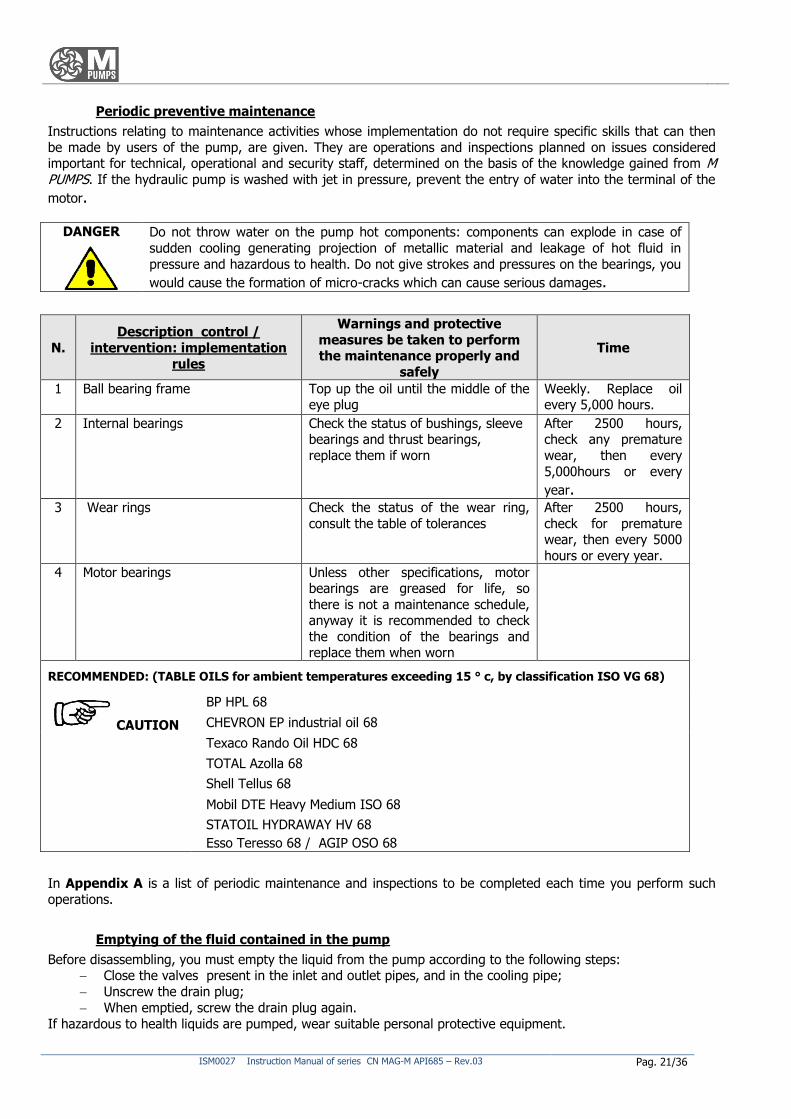
Periodic preventive maintenance
Instructions relating to maintenance activities whose implementation do not require specific skills that can then
be made by users of the pump, are given. They are operations and inspections planned on issues considered important for technical, operational and security staff, determined on the basis of the knowledge gained from M PUMPS. If the hydraulic pump is washed with jet in pressure, prevent the entry of water into the terminal of the
motor.
DANGER Do not throw water on the pump hot components: components can explode in case of
sudden cooling generating projection of metallic material and leakage of hot fluid in
pressure and hazardous to health. Do not give strokes and pressures on the bearings, you
would cause the formation of micro-cracks which can cause serious damages.
N.
Description control /
intervention: implementation
rules
Warnings and protective
measures be taken to perform the maintenance properly and
safely
Time
1 Ball bearing frame Top up the oil until the middle of the eye plug
Weekly. Replace oil every 5,000 hours.
2 Internal bearings Check the status of bushings, sleeve bearings and thrust bearings,
replace them if worn
After 2500 hours, check any premature
wear, then every
5,000hours or every year.
3 Wear rings Check the status of the wear ring,
consult the table of tolerances
After 2500 hours,
check for premature wear, then every 5000
hours or every year.
4 Motor bearings Unless other specifications, motor bearings are greased for life, so
there is not a maintenance schedule, anyway it is recommended to check
the condition of the bearings and replace them when worn
RECOMMENDED: (TABLE OILS for ambient temperatures exceeding 15 ° c, by classification ISO VG 68)
BP HPL 68
CHEVRON EP industrial oil 68
Texaco Rando Oil HDC 68
TOTAL Azolla 68
Shell Tellus 68
Mobil DTE Heavy Medium ISO 68
STATOIL HYDRAWAY HV 68
Esso Teresso 68 / AGIP OSO 68
CAUTION
In Appendix A is a list of periodic maintenance and inspections to be completed each time you perform such
operations.
Emptying of the fluid contained in the pump
Before disassembling, you must empty the liquid from the pump according to the following steps: Close the valves present in the inlet and outlet pipes, and in the cooling pipe;
Unscrew the drain plug;
When emptied, screw the drain plug again.
If hazardous to health liquids are pumped, wear suitable personal protective equipment.
Pag. 22/36 ISM0027 Instruction Manual of series CN MAG-M API685 – Rev.03
Draining the oil contained in the pump
If the pump is lubricated with oil (bare shaft versions):
remove the oil drain plug;
drain the oil and collected it without dispersing into the environment;
replace the drain plug .
If there are fluids hazardous to health, wear personal protective equipment suitable before coming into contact
with the liquid.
Extraordinary maintenance
The extraordinary maintenance operations concern the activities that are beyond those typically programmable
and executable; they require precise technical expertise by qualified personnel, and then you should contact M PUMPS. Delivery is the one shown in the header of every page of this manual.
DANGER If it becomes necessary to disassemble the pump, you must remember that the liquid
should be collected and disposed in accordance to existing environmental laws. If the pump should be sent to M PUMPS it must be drained, and should not contain any traces
of liquid pumped.
REPAIR AND PARTS REPLACEMENT
The pump must always be kept in optimum conditions of operation.
Most of the spare parts have clear and comprehensive references for their identification. It is important that the
spares are replaced by similar ones so that they can be considered equivalent in quality and safety: to order
original spare parts, contact M PUMPS referring to the model of the pump, employee number, description of the
component and the quantity needed. When you see elements with rust, cracks, etc, you must perform all replacements/repairs necessary to re-establish the conditions of the pump safe working. In any case you should always ask an opinion M PUMPS
before any intervention.
The periodic maintenance specified in the“ PERIODIC AND EXTRAORDINARY
MAINTENANCE”
To allow a smooth running for a long time is necessary to make the required maintenance.
Operators should make frequent visual inspections to check that the pump is running smoothly without noise or
vibration, and that the discharge pressure is holding steady, without fluctuation, at the correct figure. Over-heating of the pump or motor bearings is cause for alarm. The bearing housing should not be more than 50°C
above ambient temperature, nor should it exceed 80°C (too hot to touch) in any event. If the bearings overheat, shut the pump down immediately, investigate the cause, and take corrective action.
Pump disassembling
If the pump has pumped hot liquids, make sure that it has been cooled before disassembly. The pump may have pumped liquid hazardous to health is therefore necessary to wear personal protective equipment.
Before to proceed with disassembling, follow carefully the decommissioning instructions, at paragraph 20.2.
The activities of disassembly and maintenance of the pump should be conducted in full compliance with current health and safety regulations. Some spare parts may have potential health risk to the operators:
CAUTION M PUMPS disclaims any liability for damage to property and people and will invalidate the warranty if you install non original.
ISM0027 Instruction Manual of series CN MAG-M API685 – Rev.03 Pag. 23/36
MAGNETIC The pumps built by M PUMPS contain extremely strong magnets. The use of tools and work surfaces not ferromagnetic is highly recommended. The department in which you
perform maintenance must be clean and free of iron particles that may be attracted by
magnets. Pay attention to the strong magnetic attraction when you work in proximity of the
internal or external magnets. Tools can be strongly attracted by magnets, or slip from the hands causing damages to fingers and hands, moreover, the magnets maybe strongly
attracted by ferromagnetic devices present in the area.
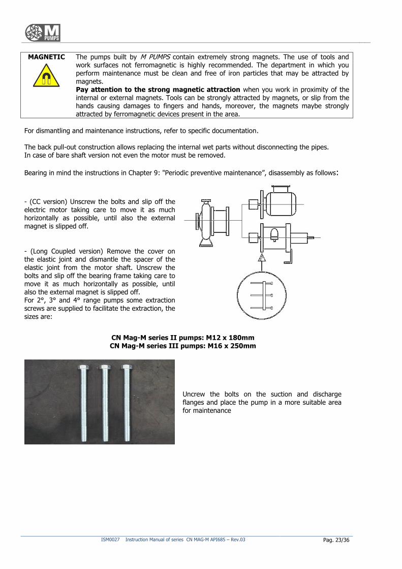
For dismantling and maintenance instructions, refer to specific documentation.
The back pull-out construction allows replacing the internal wet parts without disconnecting the pipes. In case of bare shaft version not even the motor must be removed.
Bearing in mind the instructions in Chapter 9: "Periodic preventive maintenance”, disassembly as follows:
- (CC version) Unscrew the bolts and slip off the electric motor taking care to move it as much
horizontally as possible, until also the external
magnet is slipped off.
- (Long Coupled version) Remove the cover on the elastic joint and dismantle the spacer of the
elastic joint from the motor shaft. Unscrew the
bolts and slip off the bearing frame taking care to move it as much horizontally as possible, until
also the external magnet is slipped off. For 2°, 3° and 4° range pumps some extraction
screws are supplied to facilitate the extraction, the
sizes are:
CN Mag-M series II pumps: M12 x 180mm
CN Mag-M series III pumps: M16 x 250mm
Uncrew the bolts on the suction and discharge
flanges and place the pump in a more suitable area for maintenance
Pag. 24/36 ISM0027 Instruction Manual of series CN MAG-M API685 – Rev.03
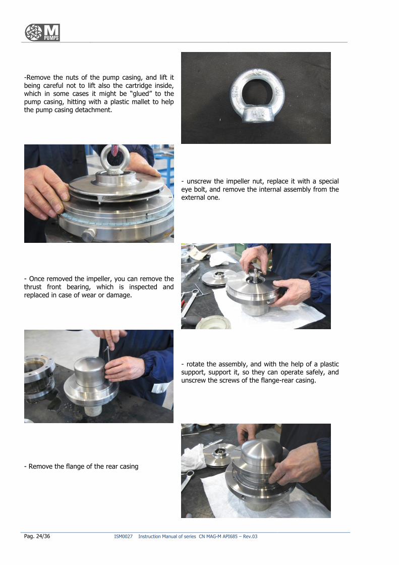
-Remove the nuts of the pump casing, and lift it
being careful not to lift also the cartridge inside, which in some cases it might be “glued” to the
pump casing, hitting with a plastic mallet to help the pump casing detachment.
- unscrew the impeller nut, replace it with a special
eye bolt, and remove the internal assembly from the external one.
- Once removed the impeller, you can remove the
thrust front bearing, which is inspected and
replaced in case of wear or damage.
- rotate the assembly, and with the help of a plastic support, support it, so they can operate safely, and
unscrew the screws of the flange-rear casing.
- Remove the flange of the rear casing
ISM0027 Instruction Manual of series CN MAG-M API685 – Rev.03 Pag. 25/36
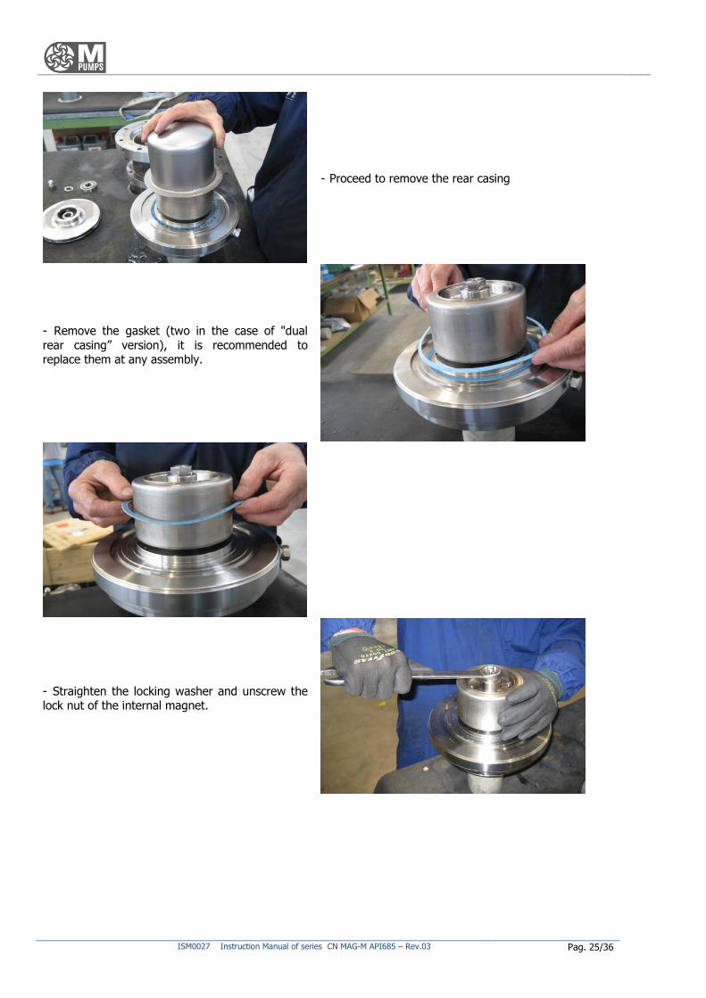
- Proceed to remove the rear casing
- Remove the gasket (two in the case of "dual
rear casing” version), it is recommended to replace them at any assembly.
- Straighten the locking washer and unscrew the lock nut of the internal magnet.
Pag. 26/36 ISM0027 Instruction Manual of series CN MAG-M API685 – Rev.03
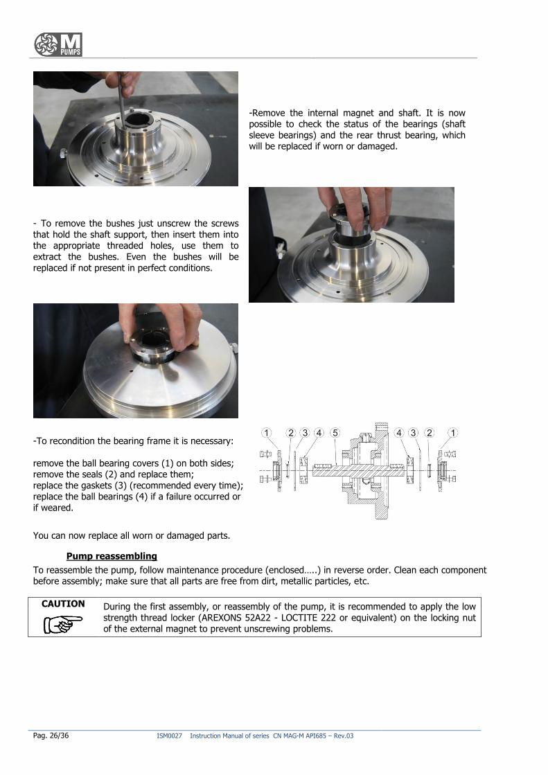
-Remove the internal magnet and shaft. It is now possible to check the status of the bearings (shaft
sleeve bearings) and the rear thrust bearing, which will be replaced if worn or damaged.
- To remove the bushes just unscrew the screws
that hold the shaft support, then insert them into the appropriate threaded holes, use them to
extract the bushes. Even the bushes will be
replaced if not present in perfect conditions.
-To recondition the bearing frame it is necessary:
remove the ball bearing covers (1) on both sides; remove the seals (2) and replace them;
replace the gaskets (3) (recommended every time); replace the ball bearings (4) if a failure occurred or
if weared.
You can now replace all worn or damaged parts.
Pump reassembling
To reassemble the pump, follow maintenance procedure (enclosed…..) in reverse order. Clean each component before assembly; make sure that all parts are free from dirt, metallic particles, etc.
CAUTION During the first assembly, or reassembly of the pump, it is recommended to apply the low
strength thread locker (AREXONS 52A22 - LOCTITE 222 or equivalent) on the locking nut of the external magnet to prevent unscrewing problems.
ISM0027 Instruction Manual of series CN MAG-M API685 – Rev.03 Pag. 27/36
DECOMMISSIONING, DISMANTLING AND DISPOSAL OF MATERIALS
Decommissioning
For an eventual long time decommissioning, it is advisable to apply some simple precautions to preserve correctly
the pump. Make the pump run with clean water (or other suitable solvent compatible with the materials of the pump) for
several minutes, in order to avoid the risk of liquid precipitation or deposits. Disconnect from the electric power /
liquid supply and place it in a protected site. During the commissioning after a long period of stocking, carefully follow all recommendations for commissioning
described at paragraph 3.5 of this manual.
CAUTION A good stocking will guarantee against unpleasant incidents during the restarting of the pump. M PUMPS disclaims any responsibility for machines stored incorrectly. If you intend
to stop using this pump it is recommended to make it inoperative.
Demolition and dismantling
The user must comply with the legislation on environmental conservation and will have to deal with the disposal
and elimination of materials and harmful substances of the pump components. It is recommended to destroy the
identification plates of the pump and any other document.
EXPLODED VIEW PART LIST
See attached documents.

Pag. 28/36 ISM0027 Instruction Manual of series CN MAG-M API685 – Rev.03
NOTES
ISM0027 Instruction Manual of series CN MAG-M API685 – Rev.03 Pag. 29/36
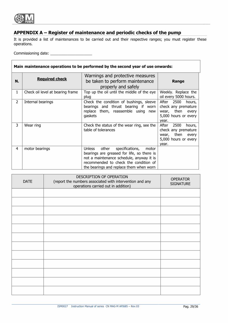
APPENDIX A – Register of maintenance and periodic checks of the pump
It is provided a list of maintenances to be carried out and their respective ranges; you must register these operations.
Commissioning date: ____________________
Main maintenance operations to be performed by the second year of use onwards:
N. Required check
Warnings and protective measures be taken to perform maintenance
properly and safely
Range
1 Check oil level at bearing frame Top up the oil until the middle of the eye plug
Weekly. Replace the oil every 5000 hours.
2 Internal bearings Check the condition of bushings, sleeve
bearings and thrust bearing if worn replace them, reassemble using new
gaskets
After 2500 hours,
check any premature wear, then every
5,000 hours or every
year.
3 Wear ring Check the status of the wear ring, see the table of tolerances
After 2500 hours,
check any premature
wear, then every 5,000 hours or every
year.
4 motor bearings Unless other specifications, motor
bearings are greased for life, so there is
not a maintenance schedule, anyway it is recommended to check the condition of
the bearings and replace them when worn
DATE
DESCRIPTION OF OPERATION
(report the numbers associated with intervention and any operations carried out in addition)
OPERATOR SIGNATURE
Pag. 30/36 ISM0027 Instruction Manual of series CN MAG-M API685 – Rev.03
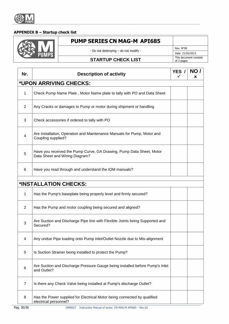
APPENDIX B – Startup check list
PUMP SERIES CN MAG-M API685
- Do not destroying – do not modify - Rev. N°00
Date 21/02/2013
STARTUP CHECK LIST This document consists of 2 pages
Nr. Description of activity YES /
NO /
*UPON ARRIVING CHECKS:
1 Check Pump Name Plate , Motor Name plate to tally with PO and Data Sheet
2 Any Cracks or damages to Pump or motor during shipment or handling
3 Check accessories if ordered to tally with PO
4
Are Installation, Operation and Maintenance Manuals for Pump, Motor and Coupling supplied?
5
Have you received the Pump Curve, GA Drawing, Pump Data Sheet, Motor Data Sheet and Wiring Diagram?
6 Have you read through and understand the IOM manuals?
*INSTALLATION CHECKS:
1 Has the Pump's baseplate being properly level and firmly secured?
2 Has the Pump and motor coupling being secured and aligned?
3
Are Suction and Discharge Pipe line with Flexible Joints being Supported and Secured?
4 Any undue Pipe loading onto Pump inlet/Outlet Nozzle due to Mis-alignment
5 Is Suction Strainer being installed to protect the Pump?
6
Are Suction and Discharge Pressure Gauge being installed before Pump's Inlet and Outlet?
7 Is there any Check Valve being installed at Pump's discharge Outlet?
8 Has the Power supplied for Electrical Motor being connected by qualified electrical personnel?
ISM0027 Instruction Manual of series CN MAG-M API685 – Rev.03 Pag. 31/36
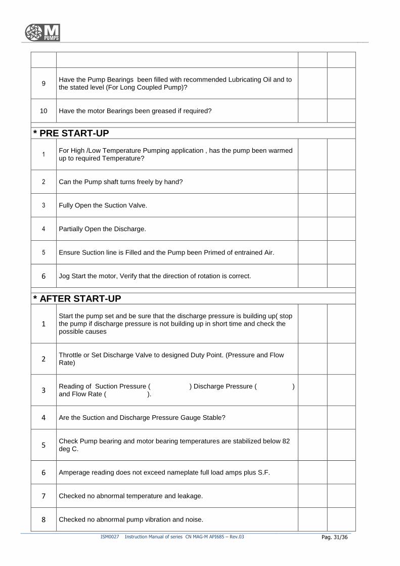
9
Have the Pump Bearings been filled with recommended Lubricating Oil and to the stated level (For Long Coupled Pump)?
10 Have the motor Bearings been greased if required?
* PRE START-UP
1
For High /Low Temperature Pumping application , has the pump been warmed up to required Temperature?
2 Can the Pump shaft turns freely by hand?
3 Fully Open the Suction Valve.
4 Partially Open the Discharge.
5 Ensure Suction line is Filled and the Pump been Primed of entrained Air.
6 Jog Start the motor, Verify that the direction of rotation is correct.
* AFTER START-UP
1
Start the pump set and be sure that the discharge pressure is building up( stop the pump if discharge pressure is not building up in short time and check the possible causes
2
Throttle or Set Discharge Valve to designed Duty Point. (Pressure and Flow Rate)
3
Reading of Suction Pressure ( ) Discharge Pressure ( ) and Flow Rate ( ).
4 Are the Suction and Discharge Pressure Gauge Stable?
5
Check Pump bearing and motor bearing temperatures are stabilized below 82 deg C.
6 Amperage reading does not exceed nameplate full load amps plus S.F.
7 Checked no abnormal temperature and leakage.
8 Checked no abnormal pump vibration and noise.
Pag. 32/36 ISM0027 Instruction Manual of series CN MAG-M API685 – Rev.03
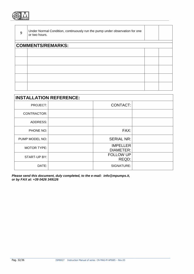
9
Under Normal Condition, continuously run the pump under observation for one or two hours.
COMMENTS/REMARKS:
INSTALLATION REFERENCE:
PROJECT: CONTACT:
CONTRACTOR:
ADDRESS:
PHONE NO: FAX:
PUMP MODEL NO: SERIAL NR:
MOTOR TYPE: IMPELLER
DIAMETER:
START-UP BY: FOLLOW UP
REQD:
DATE: SIGNATURE:
Please send this document, duly completed, to the e-mail: [email protected], or by FAX at: +39 0426 349126

ISM0027 Instruction Manual of series CN MAG-M API685 – Rev.03 Pag. 33/36

Pag. 34/36 ISM0027 Instruction Manual of series CN MAG-M API685 – Rev.03

ISM0027 Instruction Manual of series CN MAG-M API685 – Rev.03 Pag. 35/36

Pag. 36/36 ISM0027 Instruction Manual of series CN MAG-M API685 – Rev.03