Embed Size (px)
Citation preview

MAGdigital Series
MAG W 830 CMAG W 1300 CMAG 1500 CTMAG W 1500 C, CTMAG W 2200 CMAG W 2800 C, CTMAG W 3200 CT
Turbomolecular Pump with Magnetic Bearing
MAG.DRIVEdigital
Electronic Frequency Converter
Operating Instructions
Vacuum Solutions Application Support Service LEYBOLD VACUUM
GA 05.141/6.02
View our inventory
Contents Page1 Description . . . . . . . . . . . . . . . . . . . . . . . . . . . . 41.1 System overview. . . . . . . . . . . . . . . . . . . . . . . . 41.2 Compatibility with pumped media . . . . . . . . . . . 51.3 Design of the MAG . . . . . . . . . . . . . . . . . . . . . . 61.4 Function and design of the MAG.DRIVEdigital . . 61.5 Standard specification. . . . . . . . . . . . . . . . . . . . 81.6 Technical data . . . . . . . . . . . . . . . . . . . . . . . . . 10
Purge Gas. . . . . . . . . . . . . . . . . . . . . . . . . . . . 13MAG.DRIVEdigital. . . . . . . . . . . . . . . . . . . . . . 13Pump configuration . . . . . . . . . . . . . . . . . . . . . 14
1.7 Ordering data . . . . . . . . . . . . . . . . . . . . . . . . . 15
2 Installation . . . . . . . . . . . . . . . . . . . . . . . . . . . . 232.1 General safety information . . . . . . . . . . . . . . . 232.2 Unpacking - storing - transportation . . . . . . . . 242.3 Operating environment . . . . . . . . . . . . . . . . . . 242.4 Connecting the MAG to the vacuum chamber 342.5 Connecting the backing pump . . . . . . . . . . . . 362.6 Connecting the cooling water . . . . . . . . . . . . . 392.7 Connecting the purge gas. . . . . . . . . . . . . . . . 402.8 Installing the MAG.DRIVEdigital . . . . . . . . . . . . 422.8.1 Power supply connection X19. . . . . . . . . . . . . 422.8.2 Pump connection . . . . . . . . . . . . . . . . . . . . . . 422.8.3 Control plug X14 . . . . . . . . . . . . . . . . . . . . . . . 432.8.4 Interface connector . . . . . . . . . . . . . . . . . . . . . 45
3 Operation . . . . . . . . . . . . . . . . . . . . . . . . . . . . 483.1 General operation rules . . . . . . . . . . . . . . . . . 483.2 Operation with the START and STOP keys . . 503.3 Remote control . . . . . . . . . . . . . . . . . . . . . . . . 51
4 Plug-in control . . . . . . . . . . . . . . . . . . . . . . . . . 524.1 Operation with plug-in control . . . . . . . . . . . . . 524.2 Operating statuses . . . . . . . . . . . . . . . . . . . . . 544.3 Operating menu . . . . . . . . . . . . . . . . . . . . . . . 564.3.1 Basic Menu . . . . . . . . . . . . . . . . . . . . . . . . . . . 564.3.2 Menu System Info . . . . . . . . . . . . . . . . . . . . . . 574.3.3 Menu Failure Storage . . . . . . . . . . . . . . . . . . . 584.3.4 Menu Set Converter . . . . . . . . . . . . . . . . . . . . 594.3.5 Menu Set Pump . . . . . . . . . . . . . . . . . . . . . . . 614.3.6 Menu Set TMS . . . . . . . . . . . . . . . . . . . . . . . . 614.3.7 Menu Set Purge / Vent . . . . . . . . . . . . . . . . . . 614.3.8 Total view of the menu . . . . . . . . . . . . . . . . . . 624.4 Temperature Management System . . . . . . . . 644.5 Power control system (PCS). . . . . . . . . . . . . . 65
5 Maintenance . . . . . . . . . . . . . . . . . . . . . . . . . . 665.1 Cleaning . . . . . . . . . . . . . . . . . . . . . . . . . . . . . 665.2 Changing the rotor . . . . . . . . . . . . . . . . . . . . . 665.3 Changing the touch down bearings . . . . . . . . 665.4 Cleaning the frequency converter internally . . 665.5 Removing the pump from the system. . . . . . . 665.6 Service at Leybold’s . . . . . . . . . . . . . . . . . . . . 68
6 Troubleshooting. . . . . . . . . . . . . . . . . . . . . . . . 706.1 Warning messages . . . . . . . . . . . . . . . . . . . . 706.2 Failure messages . . . . . . . . . . . . . . . . . . . . . . 726.3 Malfunctions . . . . . . . . . . . . . . . . . . . . . . . . . . 77
EEC Manufacturer’s Declaration. . . . . . . . . . . 78Declaration of Conformity . . . . . . . . . . . . . . . . 79Declaration of Conformity . . . . . . . . . . . . . . . . 80Operating Instructions for MAGdigital series. . . 84
Figures
The references to diagrams, e. g. (1/2) consist of the Fig.No. and the Item No. in that order.
We reserve the right to alter the design or any data givenin these Operating Instructions. The illustrations are notbinding.
The Operating Instructions are included with the pumpand the converter. If they have different editions, theversion delivered with the pump describes the pumpcorrectly and the version delivered with the converterdescribes the converter correctly. The version numberis the digit behind the “/” in the GA No.. Example: GA05.141/5.02 is the fifth edition. See also the last page.
2 GA 05.141/6.02 - 07/2003
Description
3GA 05.141/6.02 - 07/2003
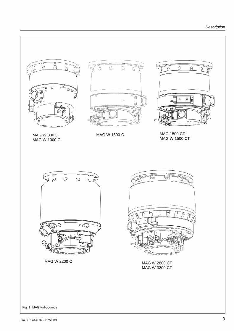
MAG W 1500 C MAG 1500 CTMAG W 1500 CT
MAG W 2200 C MAG W 2800 CTMAG W 3200 CT
Fig. 1 MAG turbopumps
MAG W 830 CMAG W 1300 C
Description
4 GA 05.141/6.02 - 07/2003
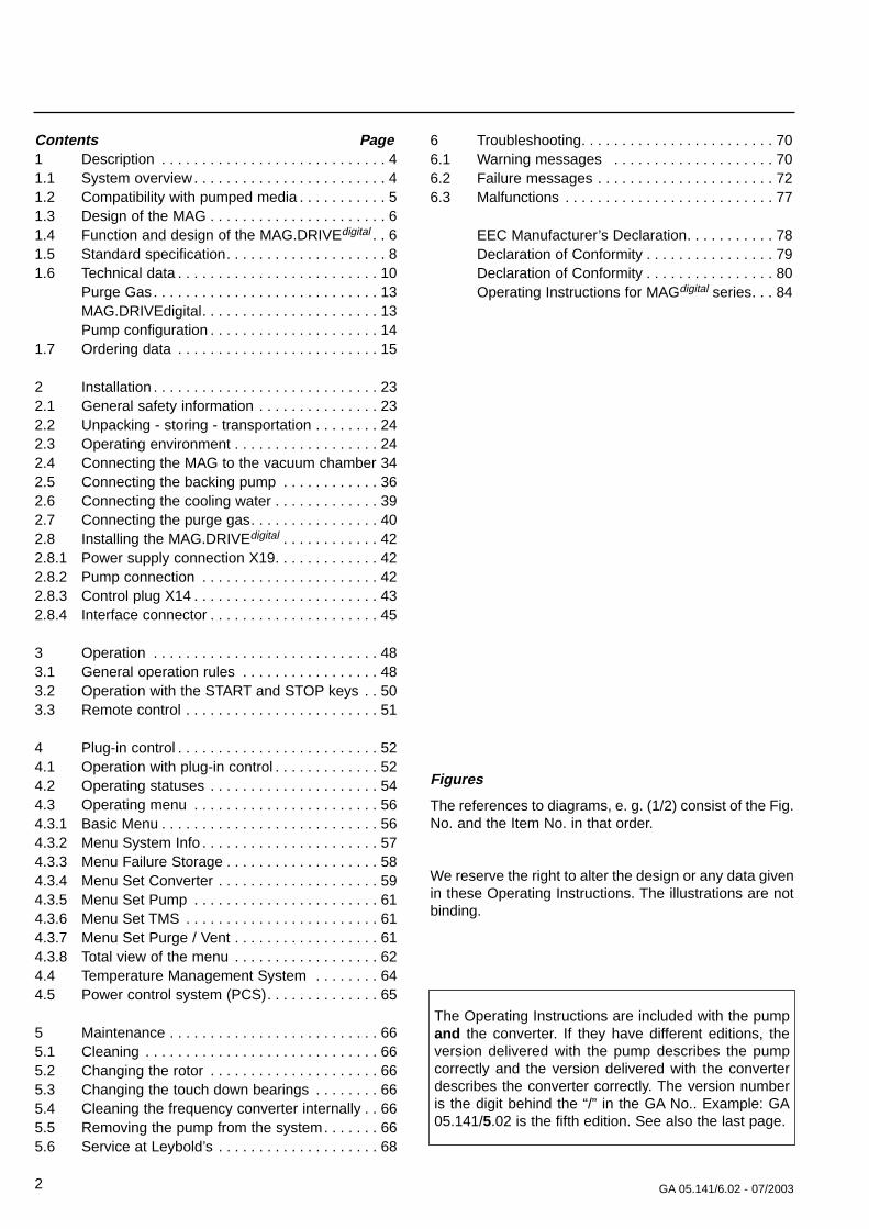
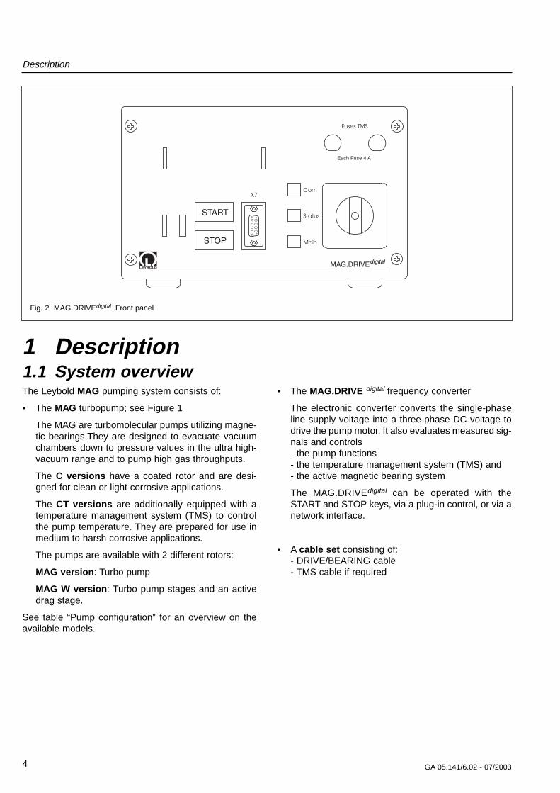
Each Fuse 4 A
Fig. 2 MAG.DRIVEdigital Front panel
1 Description1.1 System overviewThe Leybold MAG pumping system consists of:
• The MAG turbopump; see Figure 1
The MAG are turbomolecular pumps utilizing magne-tic bearings.They are designed to evacuate vacuumchambers down to pressure values in the ultra high-vacuum range and to pump high gas throughputs.
The C versions have a coated rotor and are desi-gned for clean or light corrosive applications.
The CT versions are additionally equipped with atemperature management system (TMS) to controlthe pump temperature. They are prepared for use inmedium to harsh corrosive applications.
The pumps are available with 2 different rotors:
MAG version: Turbo pump
MAG W version: Turbo pump stages and an activedrag stage.
See table “Pump configuration” for an overview on theavailable models.
• The MAG.DRIVE digital frequency converter
The electronic converter converts the single-phaseline supply voltage into a three-phase DC voltage todrive the pump motor. It also evaluates measured sig-nals and controls - the pump functions- the temperature management system (TMS) and - the active magnetic bearing system
The MAG.DRIVEdigital can be operated with theSTART and STOP keys, via a plug-in control, or via anetwork interface.
• A cable set consisting of:- DRIVE/BEARING cable- TMS cable if required
digital
Description
5GA 05.141/6.02 - 07/2003
1.2 Compatibility with pumped media
The MAG are specifically designed for the needs of thesemiconductor industry.
All materials used inside the pump are compatible withtypical gases used for semiconductor processes.
CautionPlease consult Leybold for recommendati-ons on pump models for specific processesand application requirements.
Corrosion protection
To protect the pump from corrosive gases it is mandatoryto use dry Nitrogen purge during operation of thepump.The purge gas protects the bearing section andthe motor from corrosive gases.
The rotor and the stator of the pump are KEPLA®-coatedto prevent corrosive attack caused by the processgases. The corrosion protection of the pump is effectiveonly when the pump is protected from moisture duringstandstill and storage. If the process gas contains moi-sture, contact Leybold for recommendations.
Sublimation
Some media (e.g. AlCl3) can sublimate in the pump andform deposits. Thick coatings can infringe on the requi-red operating clearence and ultimately cause the pumpto seize. These deposits can also react with moistureand generate corrosive gases (e.g. HCl).This can beco-me very critical when the pump is exposed to air. Depo-sits can be avoided in many processes by heating thepump with TMS (Temperature Management System).
The TMS is integrated in all CT-versions. The purpose ofthe TMS is to keep the pump temperature in a constantrange. To achieve the temperature the pump is equippedwith a heaterband.
Some media ( e.g. metall organic compounds ) candecompose at the hot surface of the pump and build lay-ers. Please direct any inqueries to the manufacturer.
CautionIn order to handle gases or media (e.g.AlCl3, WOCl4) which can form deposits insi-de the pump it is required to use the TMS(Temperature Management System). Thetemperature selected for such processeshas to be set to the maximum value.
Ignition danger
During operation the pressure inside the MAG is so lowthat there is no danger of ignition (at pressures belowabout 100 mbar). A hazardous condition will be createdif flammable mixtures enter the hot pump at pressuresabove 100 mbar. During operation the pump can reachtemperatures as high as 120 °C (248 °F). If the pump isdamaged, sparks could occur which could ignite explosi-ve mixtures.
Description
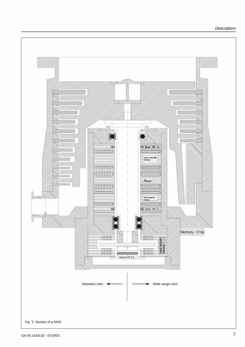
1.3 Design of the MAGThe MAG comprises basically the pump housing, themultistage rotor with the stator package, the drive, and amagnetic bearing.
Rotor
The rotor is made from a high strength aluminium alloy.The rotor and the lower stator plates are protected witha special ceramic layer ( KEPLA-COAT® ). The standardrotor is a multi-stage axial-flow turbine. In addition to theturbine stage the wide range rotor has a screw stage.
Both rotors are machined from one piece and the geo-metry of the the blades is optimized for high compressi-on and pumping speed of the typical gases used in semi-conductor manufacturing processes.
Bearings
The MAG has a built-in precision 5-axes controlledmagnetic bearing. The rotor is suspended by trouble-freemagnets:• along two orthogonal axes in each of two radial planes• and completely in the axial direction
The bearing concept allows for low vibration operationsand insures operation of the pump in any mounting posi-tion. Magnetic bearings also guarantee ultra-clean vacu-um because no grease is used for lubrication of bea-rings.
Two touch down bearings are provided to stabilize therotor mechanically if impacts occur during operation.They are only used in case of the breaking of the powersupply or BEARING cable during operation, strongshocks, or faulty electronics.
Motor and control
A DC motor without commutator is used to power therotor.
Drive voltage for the motor and the operating voltage forthe magnetic bearing are supplied by the MAG.DRIVEdi-
gital frequency converter. It also handles the automaticmonitoring of these systems.
The pump is equipped with a data storage device whichstores the important operating parameters during thecomplete operation time of the pump.
The converter monitors continously all important opera-ting parameters and provides warning and alarm signalsin case the operating conditions exceed the specificationor the set threshold.
6 GA 05.141/6.02 - 07/2003
1.4 Function and design ofthe MAG.DRIVEdigital
The MAG.DRIVEdigital electronic converter is used todrive the MAG pumps from MAG 830 to MAG 3200.
The electronic converter converts the single-phase linesupply voltage into a three-phase DC voltage to controland monitor the electronically-commutated DC motor. Italso evaluates measured signals and controls (open-loop and closed-loop) the pump functions.
The temperature management system (TMS) and themagnetic bearing control system are integrated into theconverter. The TMS regulates the pump temperature byswitching the heating on/off or cooling the pump. Thedigital magnetic bearing control system actively controlsthe pump rotor in five axes (closed-loop control).
All parameters required for pump operation and thelisted faults and operating hours are stored in a non-volatile memory in the pump. When the converter is swit-ched on, the data are loaded into the converter from thepump.
The outputs of the electronic converter are no-load andshort-circuit proof.
For remote control via control connector X14 we recom-mend that either a relay or optocoupler is used to provi-de electrical decoupling.
Housing
The converter is supplied with a closed housing. It canbe installed in a 19” cabinet; see Section 2.8.
GA 05.141/6.02 - 07/2003
Description
7
Fig. 3 Section of a MAG
Wide range rotorStandard rotor
GA 05.141/6.02 - 07/2003
Description
8
1.5 Standard specificationMAG
The turbomolecular pumps are shipped complete, sealed in a PE bag containing a desiccant.
The maximum effective life time of the desiccant is oneyear.
The intake flange is sealed with a transport seal, theforevacuum flange with a plastic cap.
For the intake flange, a centering ring with FPM O-ring,outer ring, and a splinter guard are enclosed.
We also provide the bolts for attaching the pump to yourtool. To avoid any safety risk we highly recommend usingonly the bolts provided with the pump. Refer also to Sec-tion 2.4 “Connecting the MAG ...”.
The electronic frequency converter MAG.DRIVEdigital,the cables required for operation and a seal kit to sealthe pump tightly if it is removed from the process mustbe ordered seperately.
MAG.DRIVEdigital
• Converter
• Line supply cable with USA connector, approx. 3m
• Line supply cable with EURO connector, approx. 3 m
• 2 spare fuses for the TMS (miniature fuses 5 x 20mm, F4A; according to IEC 127-2/1) and 2 fuse hol-ders 6.3 x 30 mm
• Connector for control plug X14 (pins 47/48 bridged)
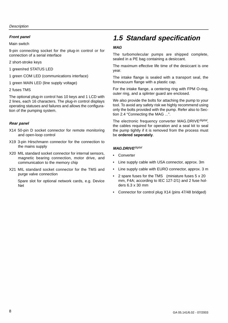
Front panel
Main switch
9-pin connecting socket for the plug-in control or forconnection of a serial interface
2 short-stroke keys
1 green/red STATUS LED
1 green COM LED (communications interface)
1 green MAIN LED (line supply voltage)
2 fuses TMS
The optional plug-in control has 10 keys and 1 LCD with2 lines, each 16 characters. The plug-in control displaysoperating statuses and failures and allows the configura-tion of the pumping system.
Rear panel
X14 50-pin D socket connector for remote monitoringand open-loop control
X19 3-pin Hirschmann connector for the connection tothe mains supply
X20 MIL standard socket connector for internal sensors,magnetic bearing connection, motor drive, andcommunication to the memory chip
X21 MIL standard socket connector for the TMS andpurge valve connection
Spare slot for optional network cards, e.g. DeviceNet
X19
X14X20
X21
Each Fuse 4 A
Start Stop
Esc Mon Prog Enter
+_
Each Fuse 4 A
GA 05.141/6.02 - 07/2003
Description
9
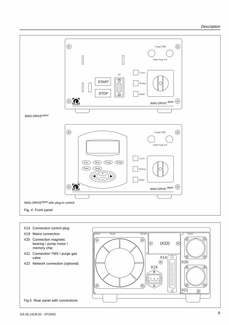
Fig. 4 Front panel
X14 Connection control plug
X19 Mains connection
X20 Connection magnetic bearing / pump motor / memory chip
X21 Connection TMS / purge gasvalve
X22 Network connection (optional)
Fig.5 Rear panel with connections
MAG.DRIVEdigital
MAG.DRIVEdigital with plug-in control
digital
digital
(X22)
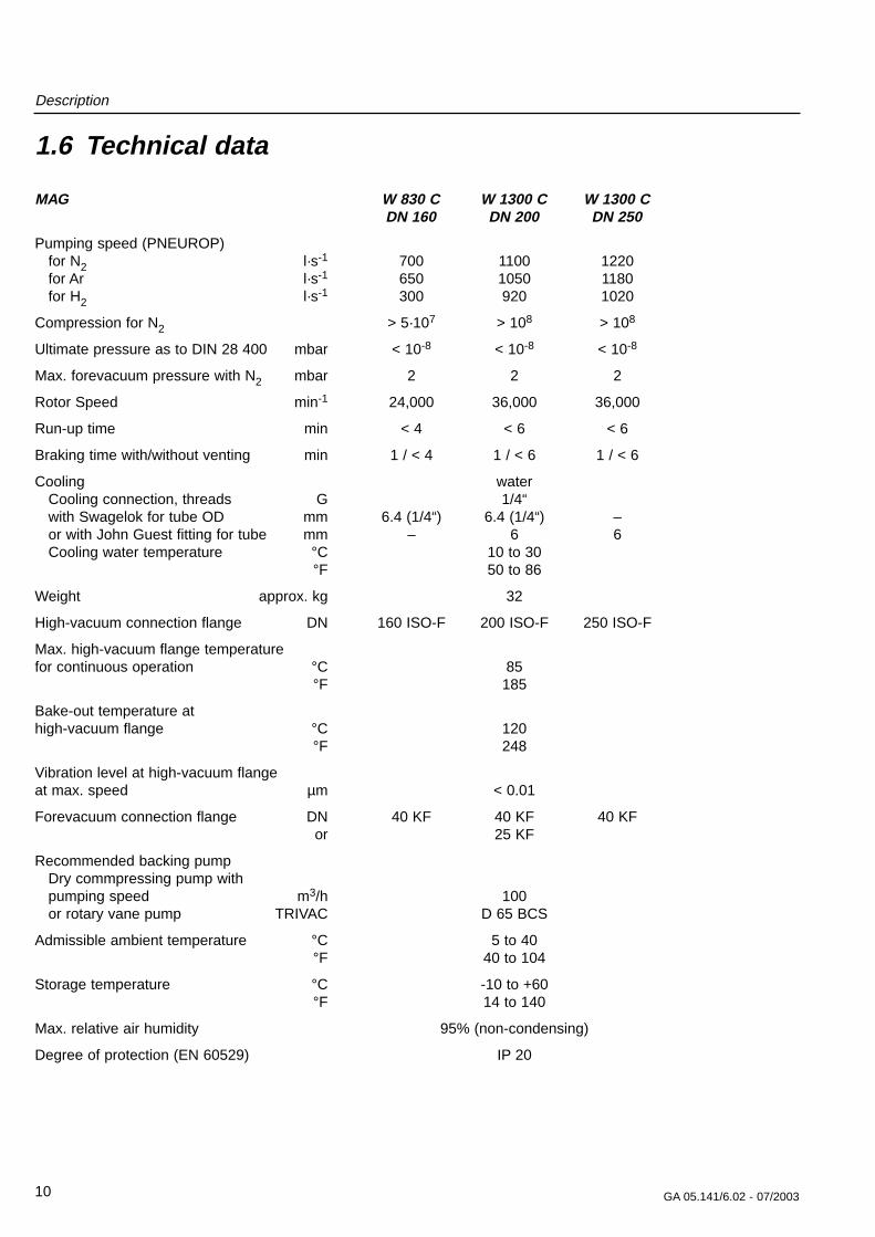
1.6 Technical data
MAG W 830 C W 1300 C W 1300 CDN 160 DN 200 DN 250
Pumping speed (PNEUROP)for N2 l·s-1 700 1100 1220for Ar l·s-1 650 1050 1180for H2 l·s-1 300 920 1020
Compression for N2 > 5·107 > 108 > 108
Ultimate pressure as to DIN 28 400 mbar < 10-8 < 10-8 < 10-8
Max. forevacuum pressure with N2 mbar 2 2 2
Rotor Speed min-1 24,000 36,000 36,000
Run-up time min < 4 < 6 < 6
Braking time with/without venting min 1 / < 4 1 / < 6 1 / < 6
Cooling waterCooling connection, threads G 1/4“with Swagelok for tube OD mm 6.4 (1/4“) 6.4 (1/4“) –or with John Guest fitting for tube mm – 6 6Cooling water temperature °C 10 to 30
°F 50 to 86
Weight approx. kg 32
High-vacuum connection flange DN 160 ISO-F 200 ISO-F 250 ISO-F
Max. high-vacuum flange temperaturefor continuous operation °C 85
°F 185
Bake-out temperature at high-vacuum flange °C 120
°F 248
Vibration level at high-vacuum flangeat max. speed µm < 0.01
Forevacuum connection flange DN 40 KF 40 KF 40 KFor 25 KF
Recommended backing pumpDry commpressing pump with pumping speed m3/h 100or rotary vane pump TRIVAC D 65 BCS
Admissible ambient temperature °C 5 to 40°F 40 to 104
Storage temperature °C -10 to +60°F 14 to 140
Max. relative air humidity 95% (non-condensing)
Degree of protection (EN 60529) IP 20
Description
10 GA 05.141/6.02 - 07/2003
Description
11GA 05.141/6.02 - 07/2003
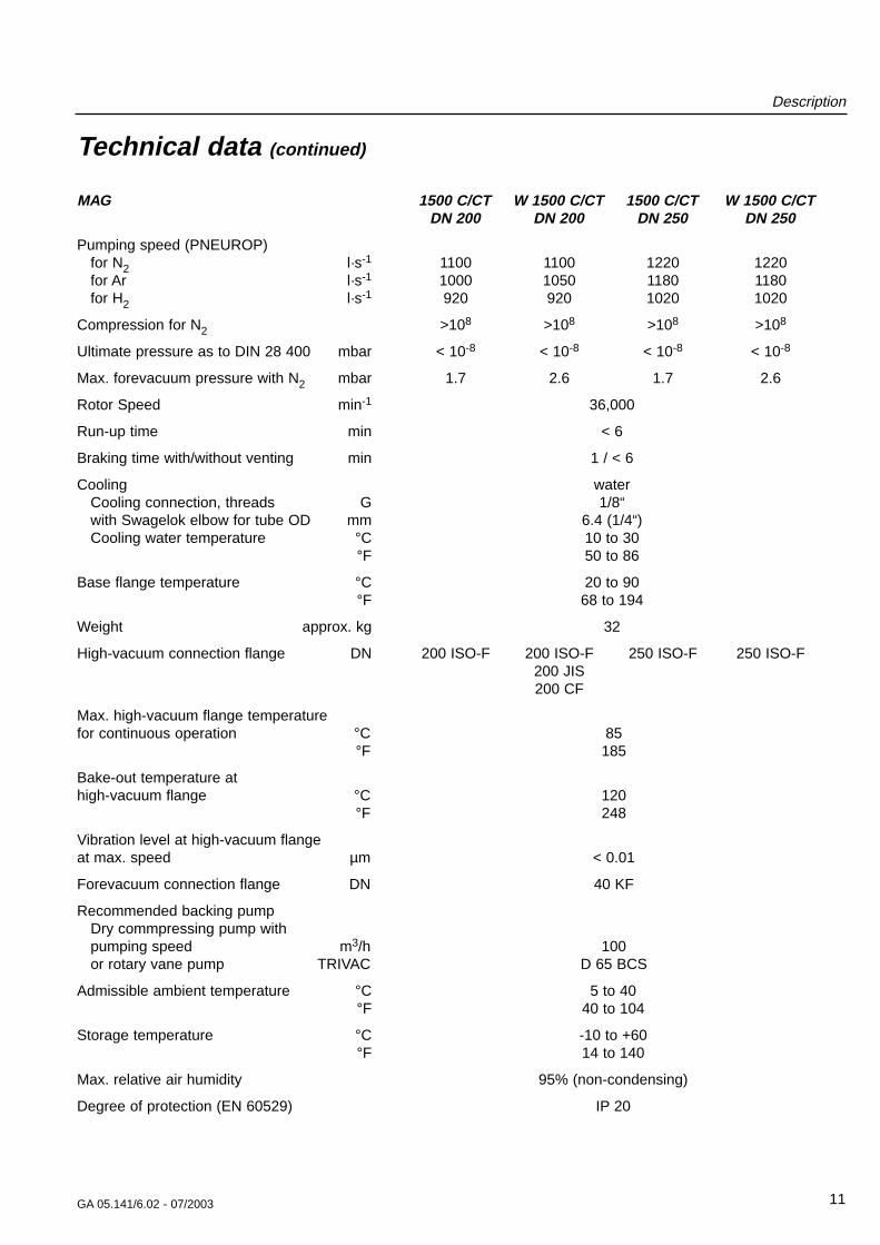
Technical data (continued)
MAG 1500 C/CT W 1500 C/CT 1500 C/CT W 1500 C/CTDN 200 DN 200 DN 250 DN 250
Pumping speed (PNEUROP)for N2 l·s-1 1100 1100 1220 1220for Ar l·s-1 1000 1050 1180 1180for H2 l·s-1 920 920 1020 1020
Compression for N2 >108 >108 >108 >108
Ultimate pressure as to DIN 28 400 mbar < 10-8 < 10-8 < 10-8 < 10-8
Max. forevacuum pressure with N2 mbar 1.7 2.6 1.7 2.6
Rotor Speed min-1 36,000
Run-up time min < 6
Braking time with/without venting min 1 / < 6
Cooling waterCooling connection, threads G 1/8“with Swagelok elbow for tube OD mm 6.4 (1/4“)Cooling water temperature °C 10 to 30
°F 50 to 86
Base flange temperature °C 20 to 90°F 68 to 194
Weight approx. kg 32
High-vacuum connection flange DN 200 ISO-F 200 ISO-F 250 ISO-F 250 ISO-F200 JIS200 CF
Max. high-vacuum flange temperaturefor continuous operation °C 85
°F 185
Bake-out temperature at high-vacuum flange °C 120
°F 248
Vibration level at high-vacuum flangeat max. speed µm < 0.01
Forevacuum connection flange DN 40 KF
Recommended backing pumpDry commpressing pump with pumping speed m3/h 100or rotary vane pump TRIVAC D 65 BCS
Admissible ambient temperature °C 5 to 40°F 40 to 104
Storage temperature °C -10 to +60°F 14 to 140
Max. relative air humidity 95% (non-condensing)
Degree of protection (EN 60529) IP 20
Description
12 GA 05.141/6.02 - 07/2003
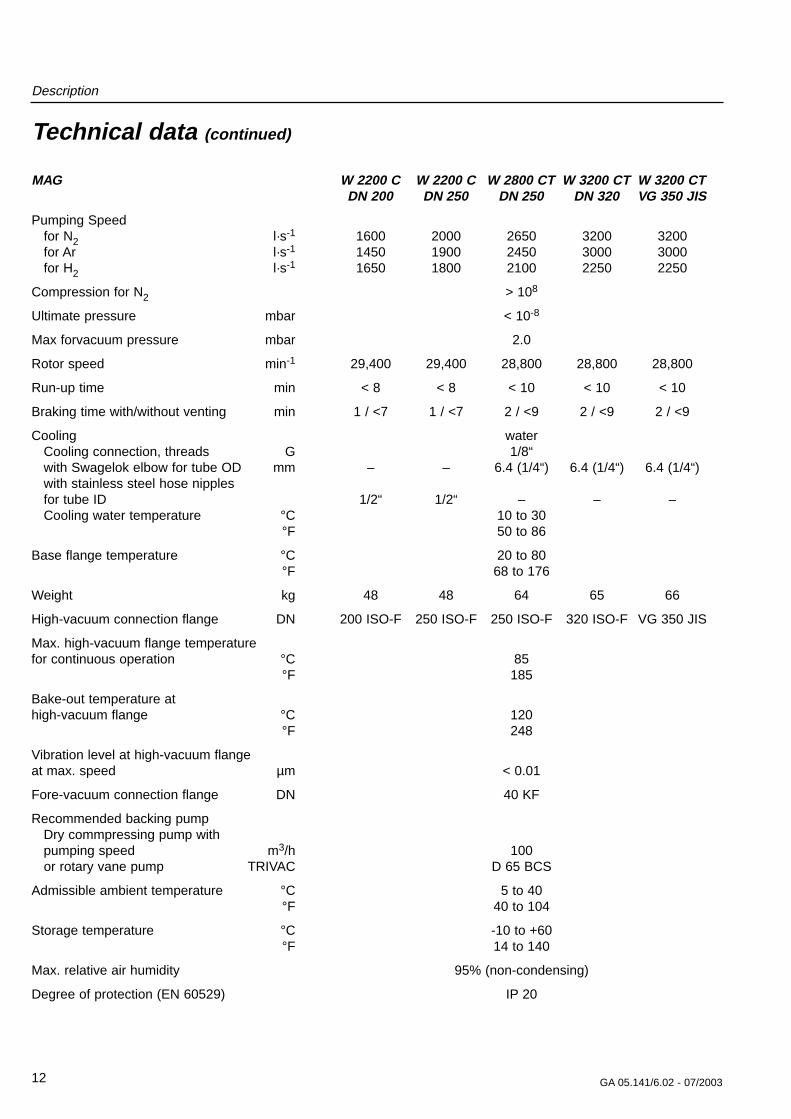
Technical data (continued)
MAG W 2200 C W 2200 C W 2800 CT W 3200 CT W 3200 CTDN 200 DN 250 DN 250 DN 320 VG 350 JIS
Pumping Speed for N2 l·s-1 1600 2000 2650 3200 3200for Ar l·s-1 1450 1900 2450 3000 3000for H2 l·s-1 1650 1800 2100 2250 2250
Compression for N2 > 108
Ultimate pressure mbar < 10-8
Max forvacuum pressure mbar 2.0
Rotor speed min-1 29,400 29,400 28,800 28,800 28,800
Run-up time min < 8 < 8 < 10 < 10 < 10
Braking time with/without venting min 1 / <7 1 / <7 2 / <9 2 / <9 2 / <9
Cooling waterCooling connection, threads G 1/8“with Swagelok elbow for tube OD mm – – 6.4 (1/4“) 6.4 (1/4“) 6.4 (1/4“)with stainless steel hose nipplesfor tube ID 1/2“ 1/2“ – – –Cooling water temperature °C 10 to 30
°F 50 to 86
Base flange temperature °C 20 to 80°F 68 to 176
Weight kg 48 48 64 65 66
High-vacuum connection flange DN 200 ISO-F 250 ISO-F 250 ISO-F 320 ISO-F VG 350 JIS
Max. high-vacuum flange temperaturefor continuous operation °C 85
°F 185
Bake-out temperature at high-vacuum flange °C 120
°F 248
Vibration level at high-vacuum flangeat max. speed µm < 0.01
Fore-vacuum connection flange DN 40 KF
Recommended backing pumpDry commpressing pump with pumping speed m3/h 100or rotary vane pump TRIVAC D 65 BCS
Admissible ambient temperature °C 5 to 40°F 40 to 104
Storage temperature °C -10 to +60°F 14 to 140
Max. relative air humidity 95% (non-condensing)
Degree of protection (EN 60529) IP 20
Description
13GA 05.141/6.02 - 07/2003
Technical data (continued)
Purge Gassee Section 2.7
MAG.DRIVEdigital
Voltage range 200 - 240 V +10% -15%Line supply frequency 50 / 60 Hz
LoadStand-by approx. 100 WMaximum heated pumps 1800 WMaximum non-heated pumps 1100 W
Max. voltage motor 60 VMaximum pump current 15 A rms
Maximum frequency 600 Hz
Load capability, relay output 42 V, 1 A
Temperature during operation 0-45 °CStorage temperature - 10 °C to + 60 °C
Relative air humidity Class F acc. to DIN 400 40
Overvoltage category IIContamination level 2in accordance with EN 61010
Weight 10 kg
0
500
1000
1500
2000
2500
3000
3500
1,00E-04 1,00E-03 1,00E-02 1,00E-01
Inlet pressure [mbar]
Pum
ping
spe
ed [l
/s]
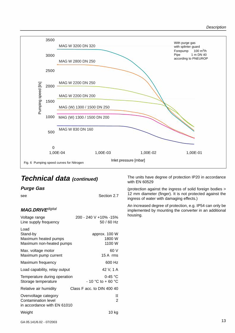
MAG W 3200 DN 320
MAG W 830 DN 160
MAG (W) 1300 / 1500 DN 250
MAG W 2200 DN 250
MAG W 2800 DN 250
MAG (W) 1300 / 1500 DN 200
MAG W 2200 DN 200
Fig. 6 Pumping speed curves for Nitrogen
With purge gaswith splinter guardForepump 100 m3/hPipe 1 m DN 40according to PNEUROP
The units have degree of protection IP20 in accordancewith EN 60529
(protection against the ingress of solid foreign bodies >12 mm diameter (finger). It is not protected against theingress of water with damaging effects.)
An increased degree of protection, e.g. IP54 can only beimplemented by mounting the converter in an additionalhousing.
Description
14 GA 05.141/6.02 - 07/2003
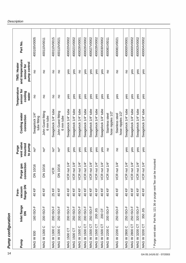
Pu
mp
co
nfi
gu
rati
on
Fo
re-
Pu
rge
Tem
per
atu
reT
MS
:H
eate
rP
um
pIn
let
flan
ge
vacu
um
P
urg
e g
asve
nt
valv
eC
oo
ling
wat
erse
nso
r fo
ran
d t
emp
erat
ure
Par
t N
o.
DN
flan
ge
DN
con
nec
tio
nm
ou
nte
d
con
nec
tio
nco
olin
gse
nso
r fo
rto
pu
mp
wat
erp
um
p c
on
tro
l
MA
G W
830
160
ISO
-F40
KF
DN
10/
16no
*S
wag
eloc
k 1/
4“no
no40
0100
V00
05tu
be f
ittin
g
MA
G W
130
0 C
200
ISO
-F40
KF
DN
10/
16no
*Jo
hn G
uest
fitt
ing
nono
4001
10V
0011
6 m
m t
ube
MA
G W
130
0 C
200
ISO
-F25
KF
VC
Rno
*S
wag
eloc
k 1/
4“ t
ube
nono
4001
10V
0015
MA
G W
130
0 C
250
ISO
-F40
KF
DN
10/
16no
*Jo
hn G
uest
fitt
ing
nono
4001
10V
0021
6 m
m t
ube
MA
G 1
500
CT
200
ISO
-F40
KF
VC
R n
ut 1
/4“
yes
Sw
agel
ock
1/4“
tub
eye
sye
s40
0020
V00
02
MA
G 1
500
CT
250
ISO
-F40
KF
VC
R n
ut 1
/4“
yes
Sw
agel
ock
1/4“
tub
eye
sye
s40
0021
V00
02
MA
G W
150
0 C
200
ISO
-F40
KF
VC
R n
ut 1
/4“
yes
Sw
agel
ock
1/4“
tub
eye
sno
4000
26V
0001
MA
G W
150
0 C
T20
0 IS
O-F
40 K
FV
CR
nut
1/4
“ye
sS
wag
eloc
k 1/
4“ t
ube
yes
yes
4000
26V
0002
MA
G W
150
0 C
T25
0 IS
O-F
40 K
FV
CR
nut
1/4
“ye
sS
wag
eloc
k 1/
4“ t
ube
yes
yes
4000
27V
0002
MA
G W
150
0 C
T20
0 JI
S40
KF
VC
R n
ut 1
/4“
yes
Sw
agel
ock
1/4“
tub
eye
sye
s40
0028
V00
02
MA
G W
150
0 C
T20
0 C
F40
KF
VC
R n
ut 1
/4“
yes
Sw
agel
ock
1/4“
tub
eye
sye
s40
0030
V00
02
MA
G W
220
0 C
200
ISO
-F40
KF
VC
R n
ut 1
/4“
noS
tain
less
ste
elye
sno
4000
81V
0011
hose
nip
ples
1/2
“
MA
G W
220
0 C
250
ISO
-F40
KF
VC
R n
ut 1
/4“
noS
tain
less
ste
elye
sno
4000
81V
0021
hose
nip
ples
1/2
“
MA
G W
280
0 C
250
ISO
-F40
KF
VC
R n
ut 1
/4“
yes
Sw
agel
ock
1/4“
tub
eye
sno
4000
00V
0001
MA
G W
280
0 C
T25
0 IS
O-F
40 K
FV
CR
nut
1/4
“ye
sS
wag
eloc
k 1/
4“ t
ube
yes
yes
4000
00V
0002
MA
G W
320
0 C
T32
0 IS
O-F
40 K
FV
CR
nut
1/4
“ye
sS
wag
eloc
k 1/
4“ t
ube
yes
yes
4000
03V
0002
MA
G W
320
0 C
T35
0 JI
S40
KF
VC
R n
ut 1
/4“
yes
Sw
agel
ock
1/4“
tub
eye
sye
s40
0004
V00
02
* P
urge
ven
t va
lve
Par
t N
o. 1
21 3
6 or
pur
ge v
ent T
ee c
an b
e m
ount
ed
Description
15GA 05.141/6.02 - 07/2003
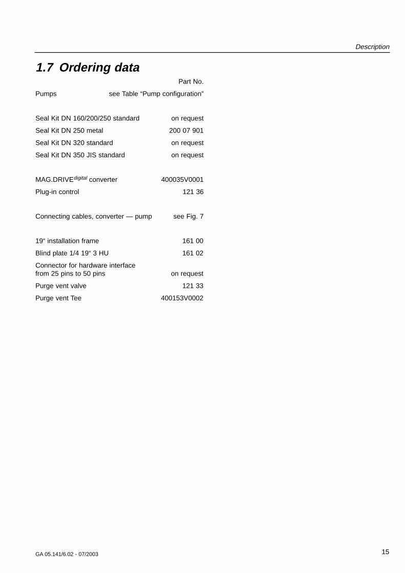
1.7 Ordering dataPart No.
Pumps see Table “Pump configuration”
Seal Kit DN 160/200/250 standard on request
Seal Kit DN 250 metal 200 07 901
Seal Kit DN 320 standard on request
Seal Kit DN 350 JIS standard on request
MAG.DRIVEdigital converter 400035V0001
Plug-in control 121 36
Connecting cables, converter — pump see Fig. 7
19“ installation frame 161 00
Blind plate 1/4 19“ 3 HU 161 02
Connector for hardware interface from 25 pins to 50 pins on request
Purge vent valve 121 33
Purge vent Tee 400153V0002
Description
16 GA 05.141/6.02 - 07/2003
0°
270°90°
180°
DRIVE/BEARINGconnection
TMS connection
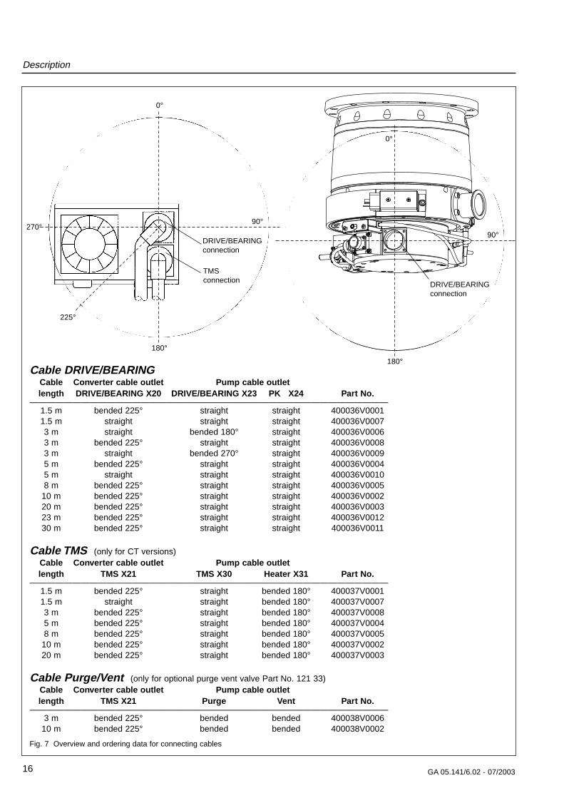
Fig. 7 Overview and ordering data for connecting cables
225°
0°
90°
DRIVE/BEARINGconnection
Cable DRIVE/BEARINGCable Converter cable outlet Pump cable outletlength DRIVE/BEARING X20 DRIVE/BEARING X23 PK X24 Part No.
——————————————————————————————————————————1.5 m bended 225° straight straight 400036V00011.5 m straight straight straight 400036V00073 m straight bended 180° straight 400036V00063 m bended 225° straight straight 400036V00083 m straight bended 270° straight 400036V00095 m bended 225° straight straight 400036V00045 m straight straight straight 400036V00108 m bended 225° straight straight 400036V0005
10 m bended 225° straight straight 400036V000220 m bended 225° straight straight 400036V000323 m bended 225° straight straight 400036V001230 m bended 225° straight straight 400036V0011
Cable TMS (only for CT versions)Cable Converter cable outlet Pump cable outletlength TMS X21 TMS X30 Heater X31 Part No.
——————————————————————————————————————————1.5 m bended 225° straight bended 180° 400037V00011.5 m straight straight bended 180° 400037V00073 m bended 225° straight bended 180° 400037V00085 m bended 225° straight bended 180° 400037V00048 m bended 225° straight bended 180° 400037V000510 m bended 225° straight bended 180° 400037V000220 m bended 225° straight bended 180° 400037V0003
Cable Purge/Vent (only for optional purge vent valve Part No. 121 33)Cable Converter cable outlet Pump cable outletlength TMS X21 Purge Vent Part No.
——————————————————————————————————————————3 m bended 225° bended bended 400038V0006
10 m bended 225° bended bended 400038V0002
180°
Description
17GA 05.141/6.02 - 07/2003
455
113
196
128135
27max. 115
122.4
198Ø 3.3
Each Fuse 4 A
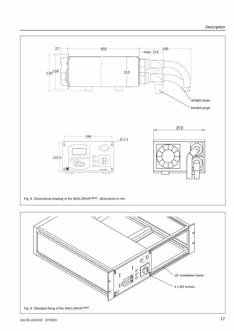
Fig. 9 Standard fixing of the MAG.DRIVEdigital
START
STOP
Com
Status
Main
X7
FusesTMS
MAG.DRIVE
Each Fuse 4 A
19“ installation frame
4 x M3 screws
straight plugs
bended plugs
Fig. 8 Dimensional drawing of the MAG.DRIVEdigital; dimensions in mm
Description
18 GA 05.141/6.02 - 07/2003
113
109.
5
D
35
Ø 260
A
Ø 262
163Ø 175
50
72
Forevacuum connection
16
31
103
98
50°30°
30°
30°30°
20°40°
R11
4,7
8.3
85
Ø 243
M8
G x
F
(=360° )
B C
E
11
F
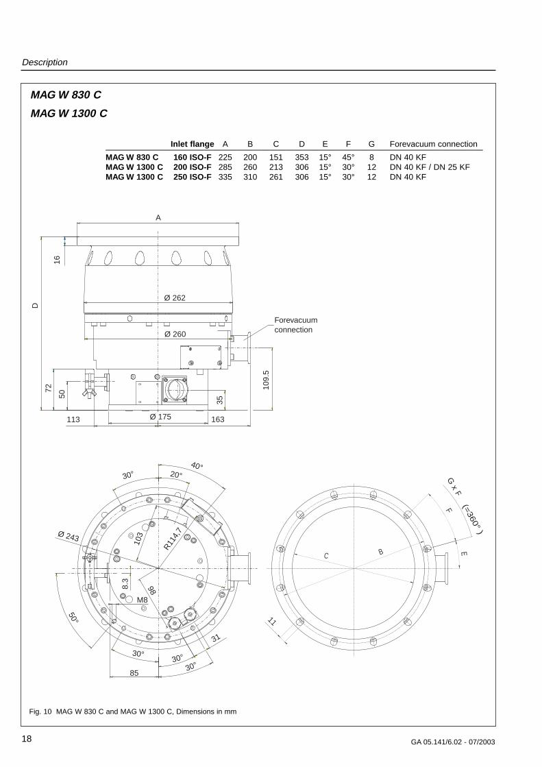
Fig. 10 MAG W 830 C and MAG W 1300 C, Dimensions in mm
MAG W 830 C
MAG W 1300 C
Inlet flange A B C D E F G Forevacuum connection——————————————————————————————————————————————MAG W 830 C 160 ISO-F 225 200 151 353 15° 45° 8 DN 40 KFMAG W 1300 C 200 ISO-F 285 260 213 306 15° 30° 12 DN 40 KF / DN 25 KFMAG W 1300 C 250 ISO-F 335 310 261 306 15° 30° 12 DN 40 KF
Description
19GA 05.141/6.02 - 07/2003
60
°
9
32
3
70°
159
150
11
Ø 260
15°
30°(=360°)
30°
12x
A
B
16
C
Ø175
164.5
20
0
23
1
279
296
307
Ø262
DN 40 KF
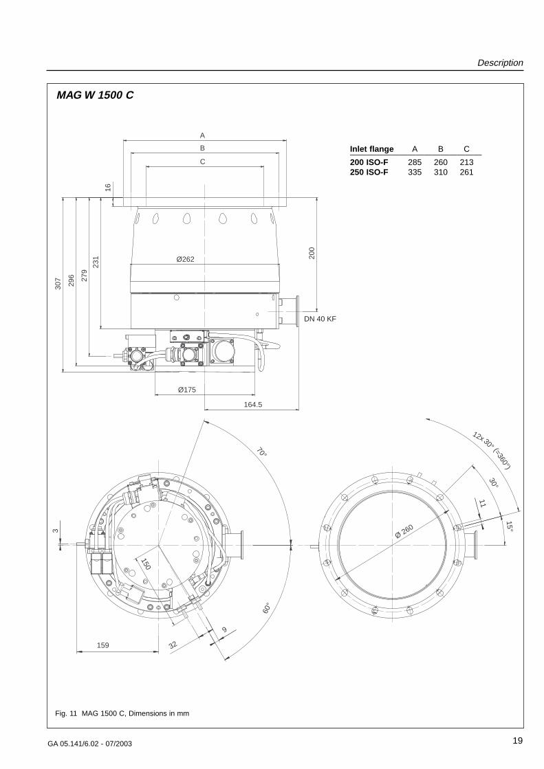
Fig. 11 MAG 1500 C, Dimensions in mm
MAG W 1500 C
Inlet flange A B C————————————————200 ISO-F 285 260 213250 ISO-F 335 310 261
Description
20 GA 05.141/6.02 - 07/2003
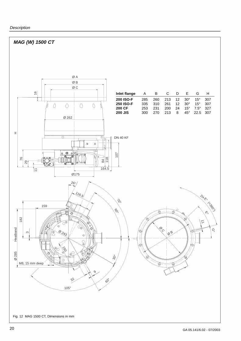
Fig. 12 MAG 1500 CT, Dimensions in mm
MAG (W) 1500 CT
Ø A
Ø B
16
Ø C
Ø175
164.5
10
7
11
29
76
H
84
11
8
Ø 262
150
159
18
2
60°
9
32
3
70°
30°
105°
60°
Ø 243
116.5
26°
M8, 15 mm deep
Hea
tban
d
Ø 2
85
11
Ø B
G
°
E°(=360°)
E°
Dx
DN 40 KF
Ø C
Inlet flange A B C D E G H———————————————————————————200 ISO-F 285 260 213 12 30° 15° 307250 ISO-F 335 310 261 12 30° 15° 307200 CF 253 231 200 24 15° 7.5° 327200 JIS 300 270 213 8 45° 22.5 307
Description
21GA 05.141/6.02 - 07/2003
85.5
78
23
B
164.6
Ø 317
A
45°
Ø 199
DN 40
8°
39
36.5°
R155
R11
7
R12
0
36°
Ø C
12 x 30° (= 360°)
15°
30°
113
Ø D
25°
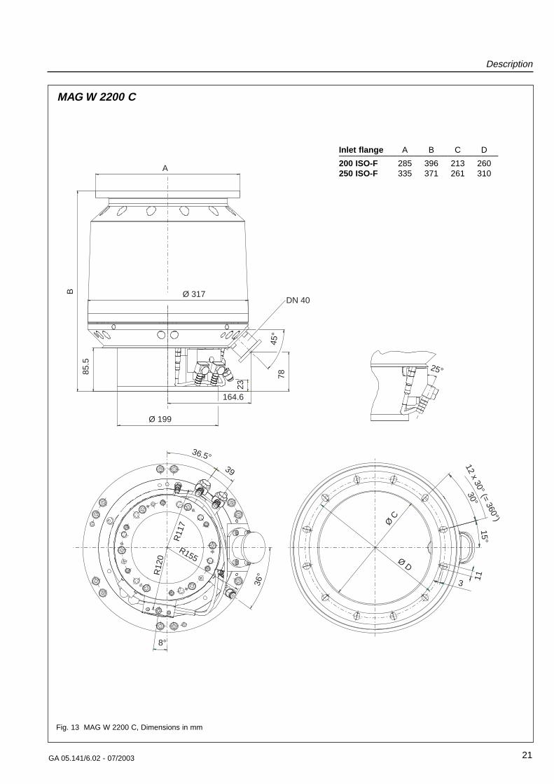
Fig. 13 MAG W 2200 C, Dimensions in mm
MAG W 2200 C
Inlet flange A B C D———————————————————200 ISO-F 285 396 213 260250 ISO-F 335 371 261 310
Description
22 GA 05.141/6.02 - 07/2003
32
50.5°
42
°
102°
137°
Ø415
30
°M
8/ 1
4 de
ep
12x30° (=360°)
B 15°
30°
E
D
DN 40
F
G
H
199
C B A
Ø 369
176
Ø353
84
196.5
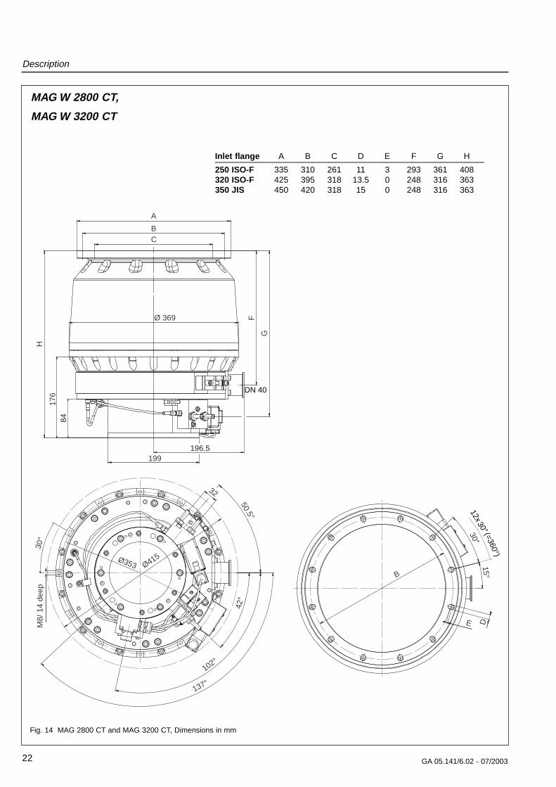
Fig. 14 MAG 2800 CT and MAG 3200 CT, Dimensions in mm
MAG W 2800 CT,
MAG W 3200 CT
Inlet flange A B C D E F G H————————————————————————————————250 ISO-F 335 310 261 11 3 293 361 408320 ISO-F 425 395 318 13.5 0 248 316 363350 JIS 450 420 318 15 0 248 316 363
Installation
23GA 05.141/6.02 - 07/2003
WarningUnauthorized opening of the convertervoids the warranty.Before opening the converter, always dis-connect it from the mains and the pump! Before disconnecting any cables make surethat the converter is switched off and thepump has come to a standstill.When applying external voltage in excessof 42 V to terminals of the device, observelocal safety regulations!Unauthorized device conversion and modi-fications are prohibited for safety reasons.
WarningThe rotor has to be changed after 40,000hours of operation or after 5000 starts/stops.
Due to high-speed and temperature, theservice life of the rotor is limited.
If the rotor is changed too late, it may bedestroyed. Thus in the flange mounts highforces and torque conditions can occur.
The mounting screws for the pump maybe torn off. When using clamped flangeconnections at the housing or with compo-nents above the housing, sudden twisting ofthe entire pump can be experienced.
The pump’s operating hours are displayed at the fre-quency converter (see Sectiont 4.3.2 ).
Only the Leybold service can change the rotor.
Please keep this Operating Instruction for future reference.
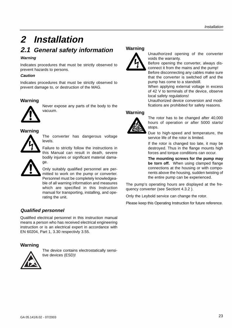
2 Installation2.1 General safety informationWarning
Indicates procedures that must be strictly observed toprevent hazards to persons.
Caution
Indicates procedures that must be strictly observed toprevent damage to, or destruction of the MAG.
WarningNever expose any parts of the body to thevacuum.
WarningThe converter has dangerous voltagelevels.
Failure to strictly follow the instructions inthis Manual can result in death, severebodily injuries or significant material dama-ge.
Only suitably qualified personnel are per-mitted to work on the pump or converter.Personnel must be completely knowledgea-ble of all warning information and measureswhich are specified in this Instructionmanual for transporting, installing, and ope-rating the unit.
Qualified personnelQualified electrical personnel in this instruction manualmeans a person who has received electrical engineeringinstruction or is an electrical expert in accordance withEN 60204, Part 1, 3.30 respectivly 3.55.
WarningThe device contains electrostatically sensi-tive devices (ESD)!
Installation
24 GA 05.141/6.02 - 07/2003
1
2
1 Aluminum cover2 Screws
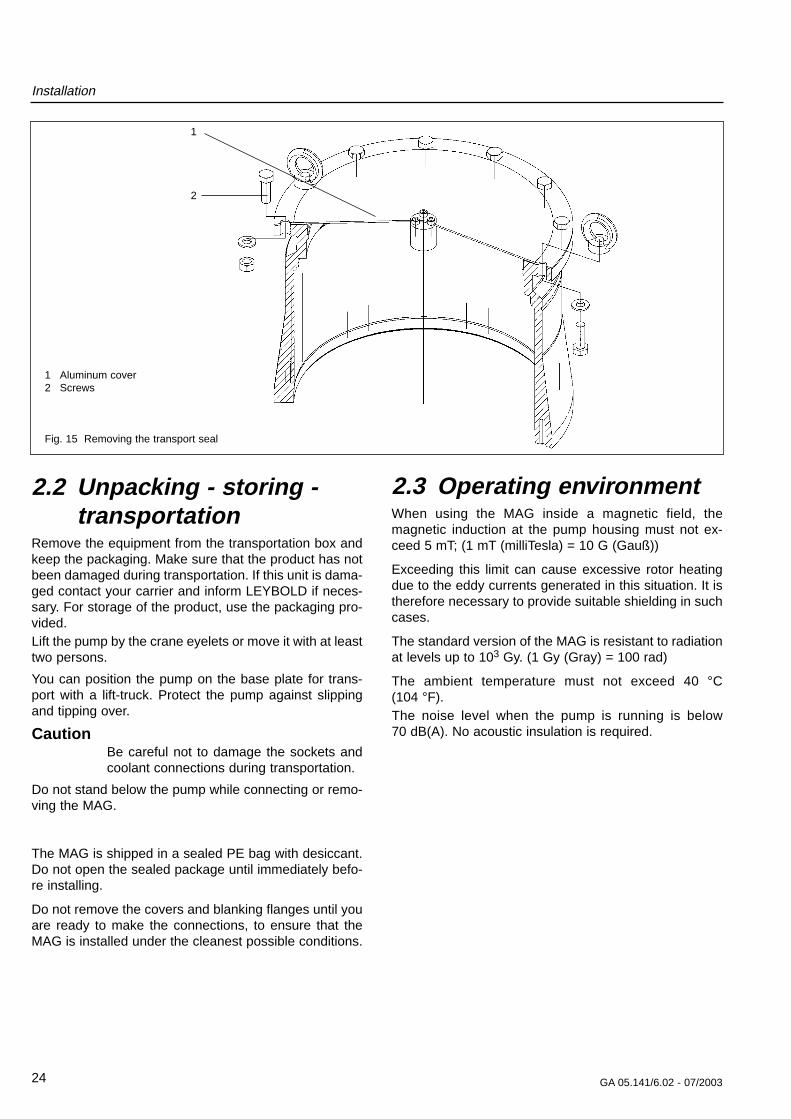
Fig. 15 Removing the transport seal
2.2 Unpacking - storing -transportation
Remove the equipment from the transportation box andkeep the packaging. Make sure that the product has notbeen damaged during transportation. If this unit is dama-ged contact your carrier and inform LEYBOLD if neces-sary. For storage of the product, use the packaging pro-vided.Lift the pump by the crane eyelets or move it with at leasttwo persons.
You can position the pump on the base plate for trans-port with a lift-truck. Protect the pump against slippingand tipping over.
CautionBe careful not to damage the sockets andcoolant connections during transportation.
Do not stand below the pump while connecting or remo-ving the MAG.
The MAG is shipped in a sealed PE bag with desiccant.Do not open the sealed package until immediately befo-re installing.
Do not remove the covers and blanking flanges until youare ready to make the connections, to ensure that theMAG is installed under the cleanest possible conditions.
2.3 Operating environmentWhen using the MAG inside a magnetic field, themagnetic induction at the pump housing must not ex-ceed 5 mT; (1 mT (milliTesla) = 10 G (Gauß))
Exceeding this limit can cause excessive rotor heatingdue to the eddy currents generated in this situation. It istherefore necessary to provide suitable shielding in suchcases.
The standard version of the MAG is resistant to radiationat levels up to 103 Gy. (1 Gy (Gray) = 100 rad)
The ambient temperature must not exceed 40 °C (104 °F).The noise level when the pump is running is below 70 dB(A). No acoustic insulation is required.
Installation
25GA 05.141/6.02 - 07/2003
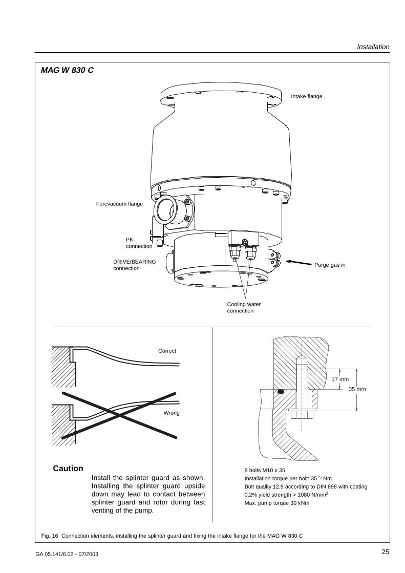
Fig. 16 Connection elements, installing the splinter guard and fixing the intake flange for the MAG W 830 C
Forevacuum flange
Purge gas in
Intake flange
DRIVE/BEARINGconnection
PKconnection
Cooling waterconnection
Correct
Wrong
35 mm
17 mm
8 bolts M10 x 35
Installation torque per bolt: 35+5 Nm
Bolt quality:12.9 according to DIN 898 with coating
0,2% yield strength > 1080 N/mm2
Max. pump torque 30 kNm
MAG W 830 C
CautionInstall the splinter guard as shown.Installing the splinter guard upsidedown may lead to contact betweensplinter guard and rotor during fastventing of the pump.
Installation
26 GA 05.141/6.02 - 07/2003
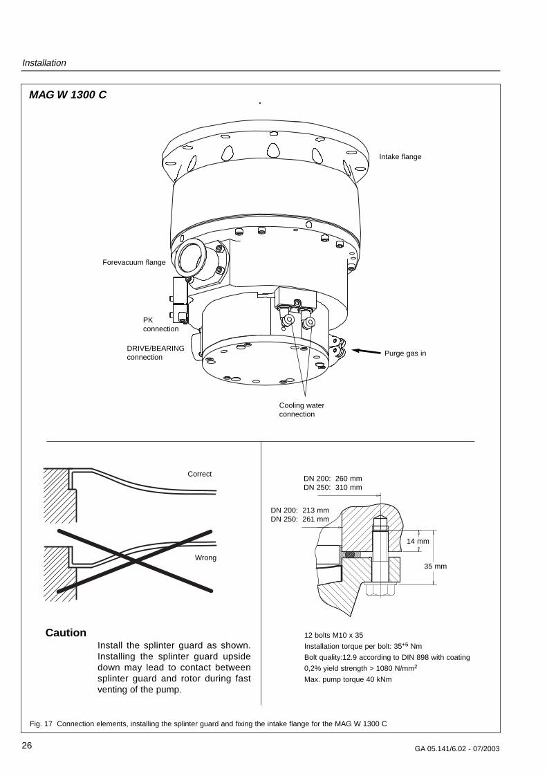
Fig. 17 Connection elements, installing the splinter guard and fixing the intake flange for the MAG W 1300 C
Forevacuum flange
Purge gas in
Intake flange
DRIVE/BEARINGconnection
PKconnection
Cooling waterconnection
12 bolts M10 x 35
Installation torque per bolt: 35+5 Nm
Bolt quality:12.9 according to DIN 898 with coating
0,2% yield strength > 1080 N/mm2
Max. pump torque 40 kNm
MAG W 1300 C
DN 200: 260 mmDN 250: 310 mm
DN 200: 213 mmDN 250: 261 mm
14 mm
35 mm
Correct
Wrong
CautionInstall the splinter guard as shown.Installing the splinter guard upsidedown may lead to contact betweensplinter guard and rotor during fastventing of the pump.
Installation
27GA 05.141/6.02 - 07/2003
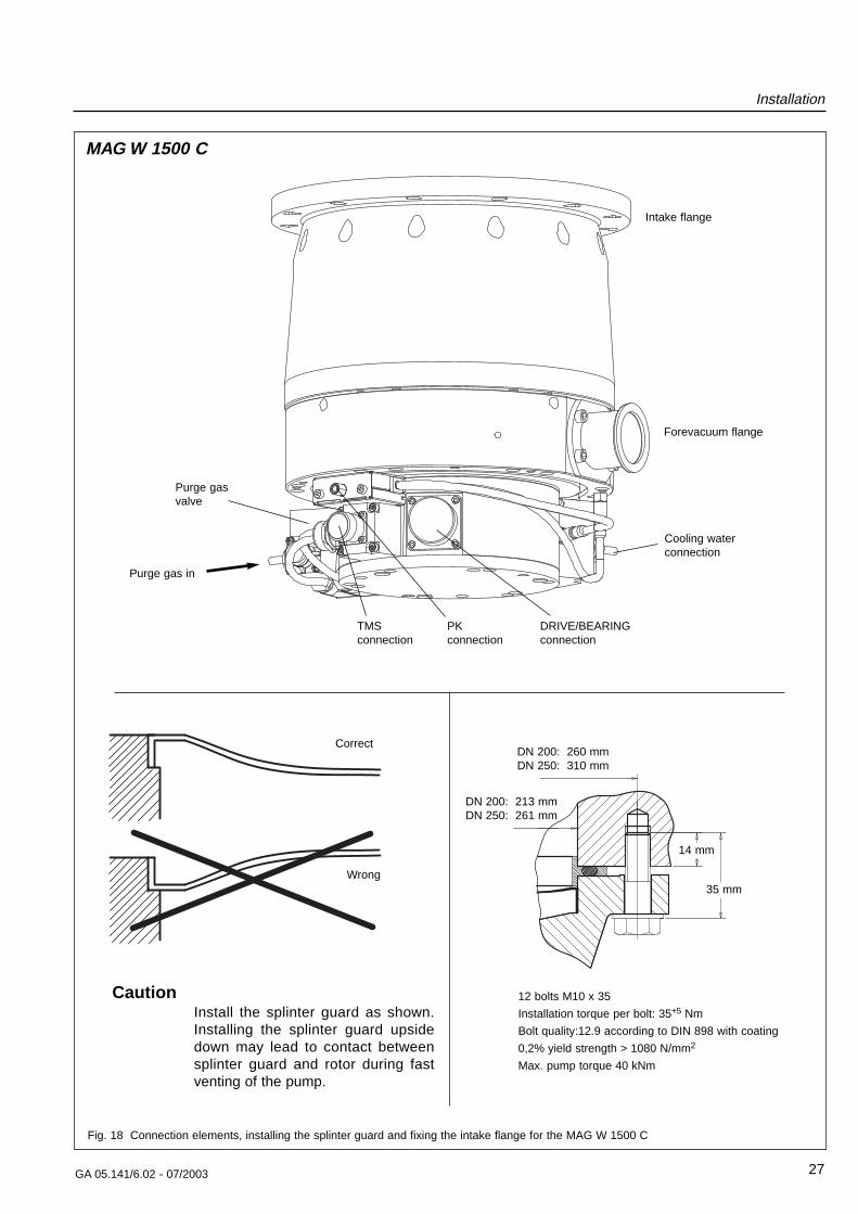
Fig. 18 Connection elements, installing the splinter guard and fixing the intake flange for the MAG W 1500 C
Forevacuum flange
Purge gasvalve
Purge gas in
Intake flange
DRIVE/BEARINGconnection
TMSconnection
PKconnection
Cooling waterconnection
Correct
Wrong
DN 200: 260 mmDN 250: 310 mm
DN 200: 213 mmDN 250: 261 mm
12 bolts M10 x 35
Installation torque per bolt: 35+5 Nm
Bolt quality:12.9 according to DIN 898 with coating
0,2% yield strength > 1080 N/mm2
Max. pump torque 40 kNm
14 mm
35 mm
MAG W 1500 C
CautionInstall the splinter guard as shown.Installing the splinter guard upsidedown may lead to contact betweensplinter guard and rotor during fastventing of the pump.
GA 05.141/6.02 - 07/2003
Installation
28
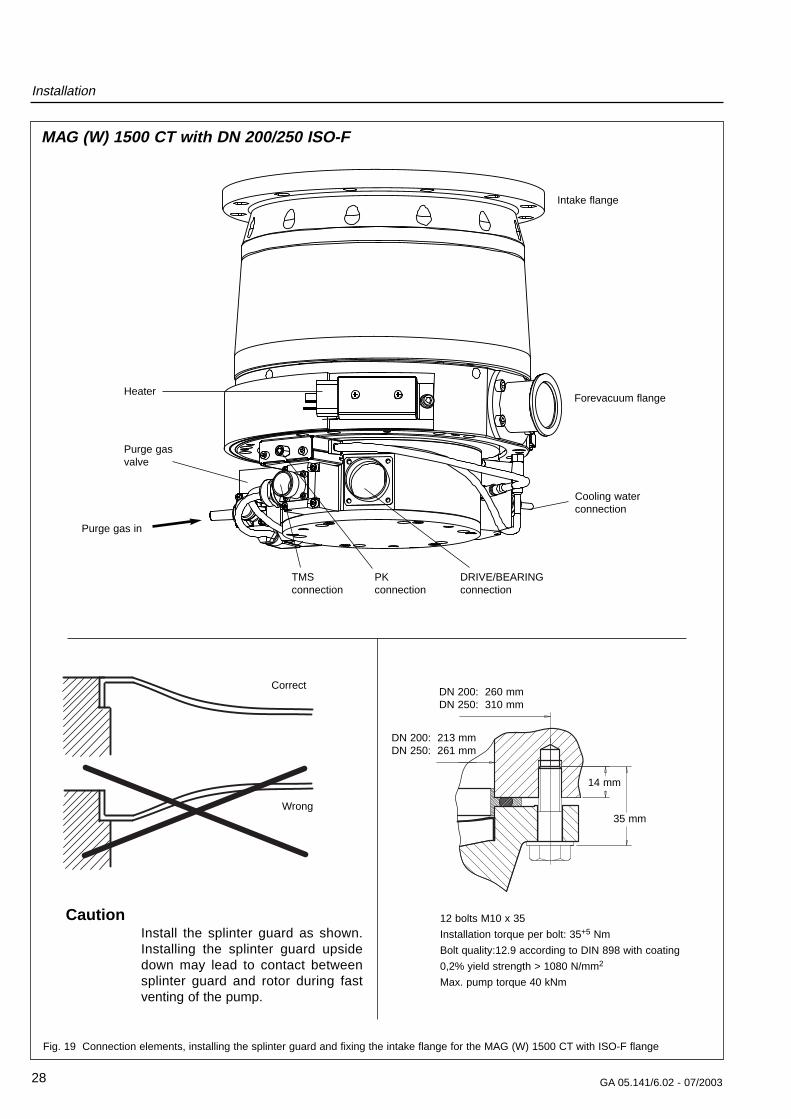
Fig. 19 Connection elements, installing the splinter guard and fixing the intake flange for the MAG (W) 1500 CT with ISO-F flange
Forevacuum flange
Purge gasvalve
Purge gas in
Intake flange
DRIVE/BEARINGconnection
TMSconnection
PKconnection
Heater
Cooling waterconnection
12 bolts M10 x 35
Installation torque per bolt: 35+5 Nm
Bolt quality:12.9 according to DIN 898 with coating
0,2% yield strength > 1080 N/mm2
Max. pump torque 40 kNm
MAG (W) 1500 CT with DN 200/250 ISO-F
DN 200: 260 mmDN 250: 310 mm
DN 200: 213 mmDN 250: 261 mm
14 mm
35 mm
Correct
Wrong
CautionInstall the splinter guard as shown.Installing the splinter guard upsidedown may lead to contact betweensplinter guard and rotor during fastventing of the pump.
Installation
29GA 05.141/6.02 - 07/2003
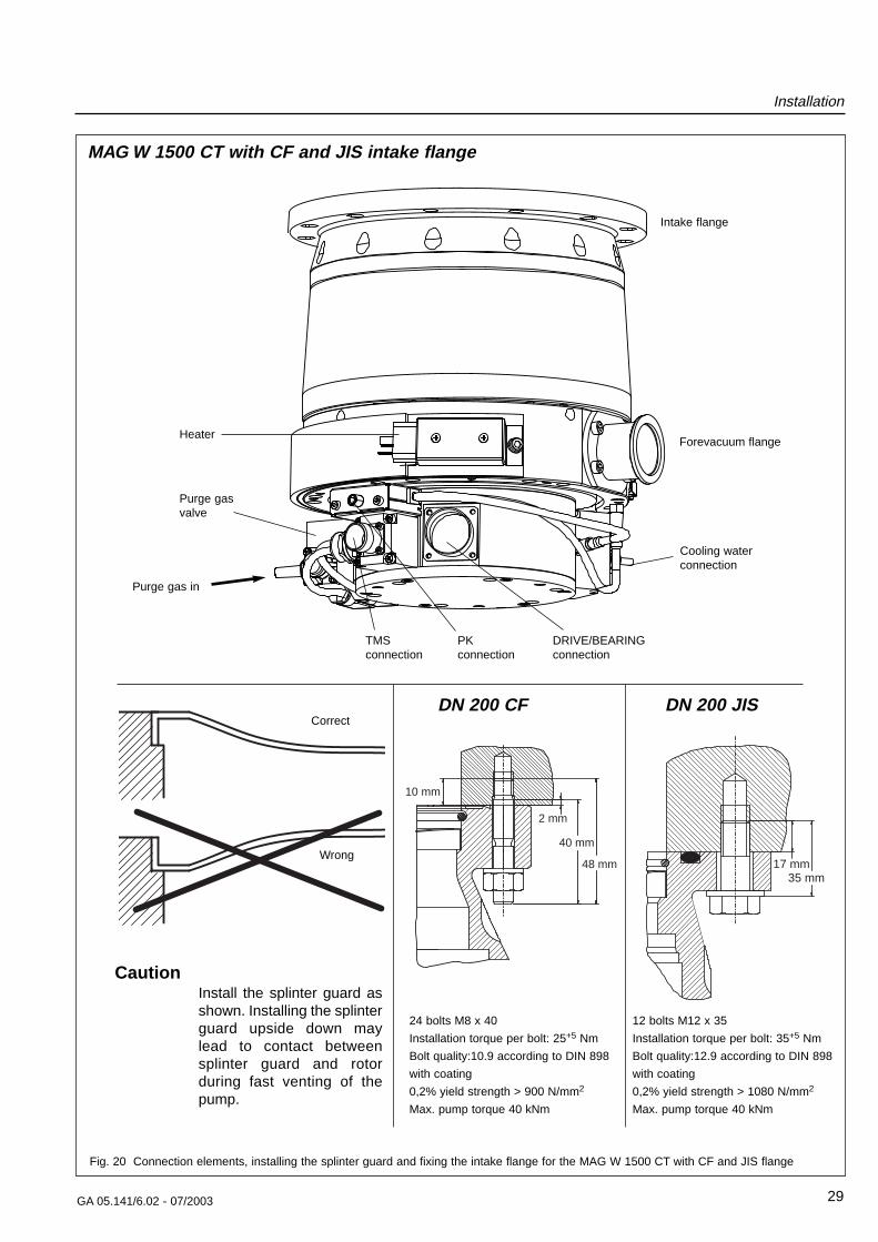
Fig. 20 Connection elements, installing the splinter guard and fixing the intake flange for the MAG W 1500 CT with CF and JIS flange
Forevacuum flange
Purge gasvalve
Purge gas in
Intake flange
DRIVE/BEARINGconnection
TMSconnection
PKconnection
Heater
Cooling waterconnection
24 bolts M8 x 40
Installation torque per bolt: 25+5 Nm
Bolt quality:10.9 according to DIN 898
with coating
0,2% yield strength > 900 N/mm2
Max. pump torque 40 kNm
MAG W 1500 CT with CF and JIS intake flange
Correct
Wrong
CautionInstall the splinter guard asshown. Installing the splinterguard upside down maylead to contact betweensplinter guard and rotorduring fast venting of thepump.
48 mm
40 mm
2 mm
10 mm
DN 200 CF
35 mm17 mm
DN 200 JIS
12 bolts M12 x 35
Installation torque per bolt: 35+5 Nm
Bolt quality:12.9 according to DIN 898
with coating
0,2% yield strength > 1080 N/mm2
Max. pump torque 40 kNm
Installation
30 GA 05.141/6.02 - 07/2003
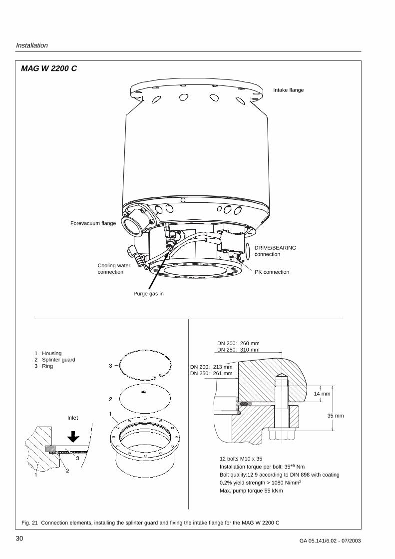
Fig. 21 Connection elements, installing the splinter guard and fixing the intake flange for the MAG W 2200 C
Forevacuum flange
Purge gas in
Intake flange
DRIVE/BEARINGconnection
PK connectionCooling waterconnection
12 bolts M10 x 35
Installation torque per bolt: 35+5 Nm
Bolt quality:12.9 according to DIN 898 with coating
0,2% yield strength > 1080 N/mm2
Max. pump torque 55 kNm
14 mm
35 mm
MAG W 2200 C
1 Housing2 Splinter guard3 Ring DN 200: 213 mm
DN 250: 261 mm
DN 200: 260 mmDN 250: 310 mm
Installation
31GA 05.141/6.02 - 07/2003
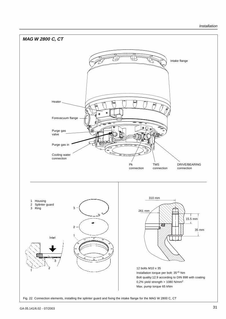
Fig. 22 Connection elements, installing the splinter guard and fixing the intake flange for the MAG W 2800 C, CT
Forevacuum flange
Purge gasvalve
Purge gas in
Intake flange
DRIVE/BEARINGconnection
Pkconnection
TMSconnection
Heater
Cooling waterconnection
12 bolts M10 x 35
Installation torque per bolt: 35+5 Nm
Bolt quality:12.9 according to DIN 898 with coating
0,2% yield strength > 1080 N/mm2
Max. pump torque 65 kNm
MAG W 2800 C, CT
310 mm
261 mm
15.5 mm
35 mm
1 Housing2 Splinter guard3 Ring
Installation
32 GA 05.141/6.02 - 07/2003
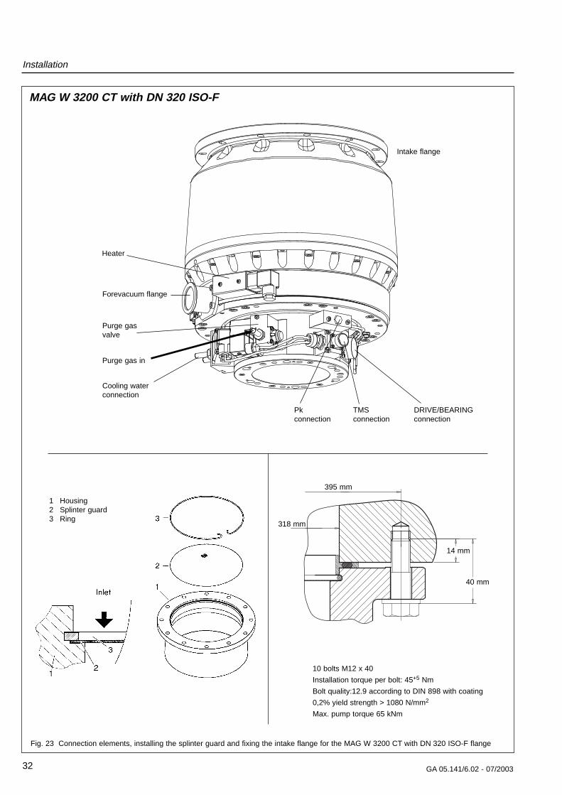
Fig. 23 Connection elements, installing the splinter guard and fixing the intake flange for the MAG W 3200 CT with DN 320 ISO-F flange
Forevacuum flange
Purge gasvalve
Purge gas in
Intake flange
DRIVE/BEARINGconnection
Pkconnection
TMSconnection
Heater
Cooling waterconnection
10 bolts M12 x 40
Installation torque per bolt: 45+5 Nm
Bolt quality:12.9 according to DIN 898 with coating
0,2% yield strength > 1080 N/mm2
Max. pump torque 65 kNm
MAG W 3200 CT with DN 320 ISO-F
1 Housing2 Splinter guard3 Ring
395 mm
318 mm
14 mm
40 mm
Installation
33GA 05.141/6.02 - 07/2003
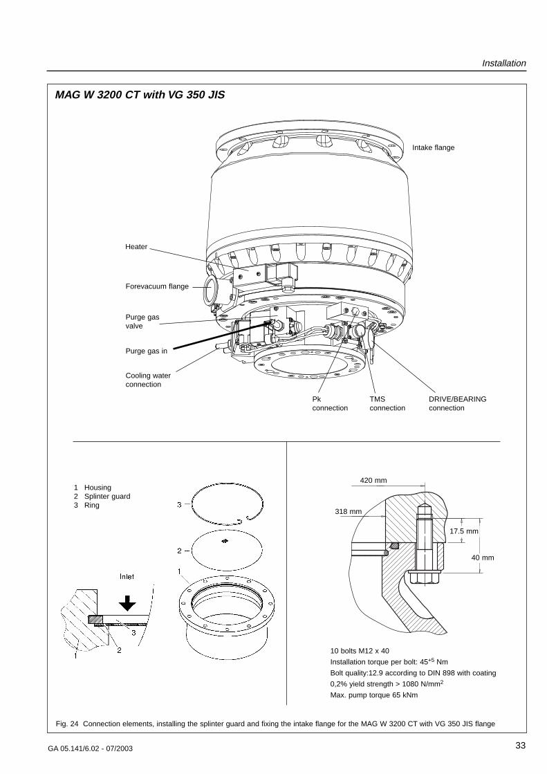
Fig. 24 Connection elements, installing the splinter guard and fixing the intake flange for the MAG W 3200 CT with VG 350 JIS flange
Forevacuum flange
Purge gasvalve
Purge gas in
Intake flange
DRIVE/BEARINGconnection
Pkconnection
TMSconnection
Heater
Cooling waterconnection
10 bolts M12 x 40
Installation torque per bolt: 45+5 Nm
Bolt quality:12.9 according to DIN 898 with coating
0,2% yield strength > 1080 N/mm2
Max. pump torque 65 kNm
MAG W 3200 CT with VG 350 JIS
420 mm
318 mm
17.5 mm
40 mm
1 Housing2 Splinter guard3 Ring
Installation
34 GA 05.141/6.02 - 07/2003
2.4 Connecting the MAG tothe vacuum chamber
The MAG is shipped in a sealed PE bag with desiccant.Do not open the package until immediately before instal-ling.
Do not remove the covers and blanking flanges until youare ready to make the connections, to ensure that theMAG is installed under the cleanest possible conditions.
Pay attention to maximum cleanliness when connecting.
Remove the transport seal from the intake flange. To doso unscrew the screws (15/2) and remove the aluminumcover. We recommend saving the transport seal formaintenance.
Foreign objects entering the pump through the high-va-cuum flange can cause serious damage to the rotor.That’s why the splinter guard must always be installed.
Damages caused during operation without the splinterguard are excluded from warranty.
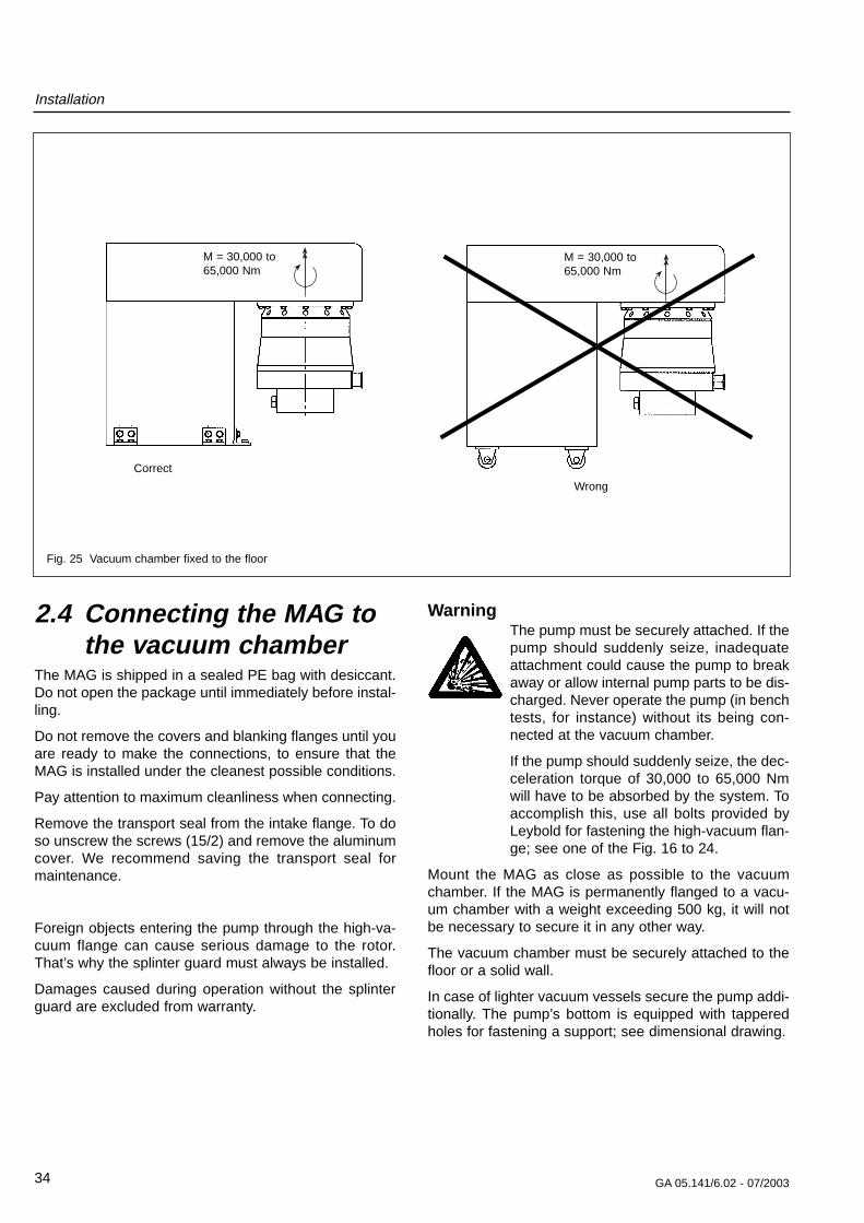
WarningThe pump must be securely attached. If thepump should suddenly seize, inadequateattachment could cause the pump to breakaway or allow internal pump parts to be dis-charged. Never operate the pump (in benchtests, for instance) without its being con-nected at the vacuum chamber.
If the pump should suddenly seize, the dec-celeration torque of 30,000 to 65,000 Nmwill have to be absorbed by the system. Toaccomplish this, use all bolts provided byLeybold for fastening the high-vacuum flan-ge; see one of the Fig. 16 to 24.
Mount the MAG as close as possible to the vacuumchamber. If the MAG is permanently flanged to a vacu-um chamber with a weight exceeding 500 kg, it will notbe necessary to secure it in any other way.
The vacuum chamber must be securely attached to thefloor or a solid wall.
In case of lighter vacuum vessels secure the pump addi-tionally. The pump’s bottom is equipped with tapperedholes for fastening a support; see dimensional drawing.
Correct
Wrong
Fig. 25 Vacuum chamber fixed to the floor
M = 30,000 to65,000 Nm
M = 30,000 to65,000 Nm
Installation
35GA 05.141/6.02 - 07/2003
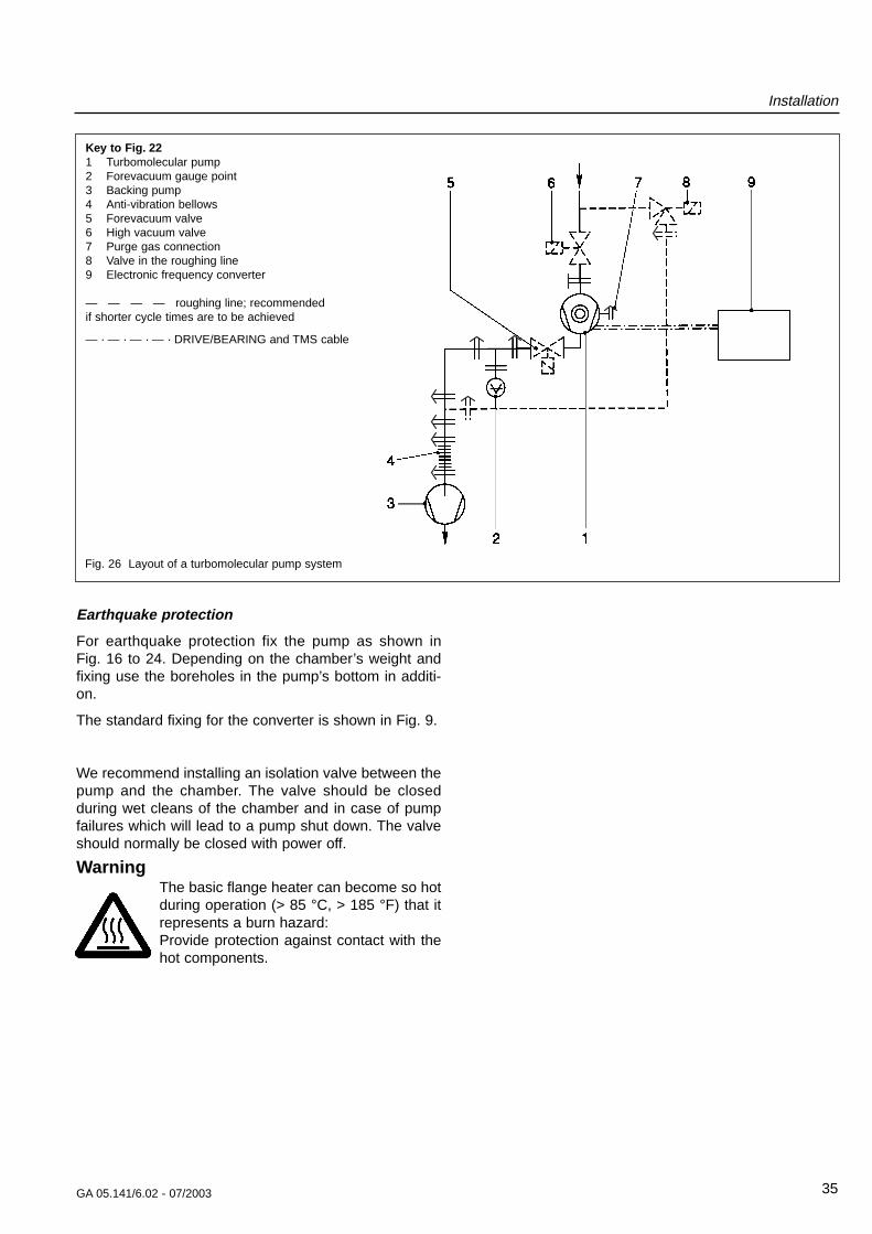
Fig. 26 Layout of a turbomolecular pump system
Key to Fig. 221 Turbomolecular pump2 Forevacuum gauge point3 Backing pump4 Anti-vibration bellows5 Forevacuum valve6 High vacuum valve7 Purge gas connection8 Valve in the roughing line9 Electronic frequency converter
— — — — roughing line; recommendedif shorter cycle times are to be achieved
— · — · — · — · DRIVE/BEARING and TMS cable
Earthquake protection
For earthquake protection fix the pump as shown in Fig. 16 to 24. Depending on the chamber’s weight andfixing use the boreholes in the pump’s bottom in additi-on.
The standard fixing for the converter is shown in Fig. 9.
We recommend installing an isolation valve between thepump and the chamber. The valve should be closedduring wet cleans of the chamber and in case of pumpfailures which will lead to a pump shut down. The valveshould normally be closed with power off.
WarningThe basic flange heater can become so hotduring operation (> 85 °C, > 185 °F) that itrepresents a burn hazard:Provide protection against contact with thehot components.
Installation
36 GA 05.141/6.02 - 07/2003
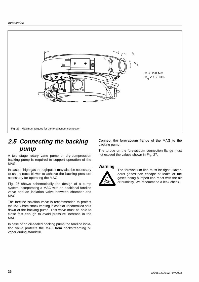
2.5 Connecting the backingpump
A two stage rotary vane pump or dry-compressionbacking pump is required to support operation of theMAG.
In case of high gas throughput, it may also be necessaryto use a roots blower to achieve the backing pressurenecessary for operating the MAG.
Fig. 26 shows schematically the design of a pumpsystem incorporating a MAG with an additional forelinevalve and an isolation valve between chamber andMAG.
The foreline isolation valve is recommended to protectthe MAG from shock venting in case of uncontrolled shutdown of the backing pump. This valve must be able toclose fast enough to avoid pressure increase in theMAG.
In case of an oil-sealed backing pump the foreline isola-tion valve protects the MAG from backstreaming oilvapor during standstill.
Connect the forevacuum flange of the MAG to thebacking pump.
The torque on the forevacuum connection flange mustnot exceed the values shown in Fig. 27.
WarningThe forevacuum line must be tight. Hazar-dous gases can escape at leaks or thegases being pumped can react with the airor humidity. We recommend a leak check.
M < 150 NmMq < 150 Nm
Fig. 27 Maximum torques for the forevacuum connection
M
Mq
Installation
37GA 05.141/6.02 - 07/2003
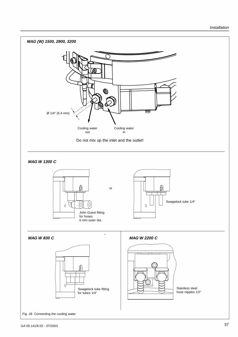
Fig. 28 Connecting the cooling water
Cooling water Cooling waterout in
Ø 1/4“ (6.4 mm)
MAG (W) 1500, 2800, 3200
Do not mix up the inlet and the outlet!
MAG W 2200 C
Stainless steelhose nipples 1/2“
John Guest fittingfor hoses 6 mm outer dia.
MAG W 830 C
Swagelock tube fittingfor tubes 1/4“
MAG W 1300 C
Swagelock tube 1/4“
or
Installation
38 GA 05.141/6.02 - 07/2003
5 10 15 20 25 30 35 40°C
350
300
250
200
150
120100
50
0
l/h
Operation window
0 1 2 3 4 5bar
400
350
300
250
200
150
100
50
0
l/h MAG (W) 1500/2800/3200 CT:Bypass operation
All pumps: Cooling
Flo
w
Temperature
Flo
w
Differential pressurebetween inlet and outlet
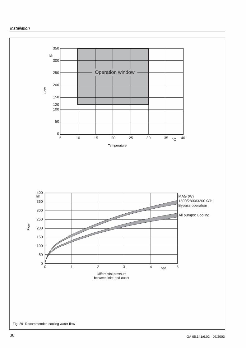
Fig. 29 Recommended cooling water flow
Installation
39GA 05.141/6.02 - 07/2003
Pump cooling
Bypass
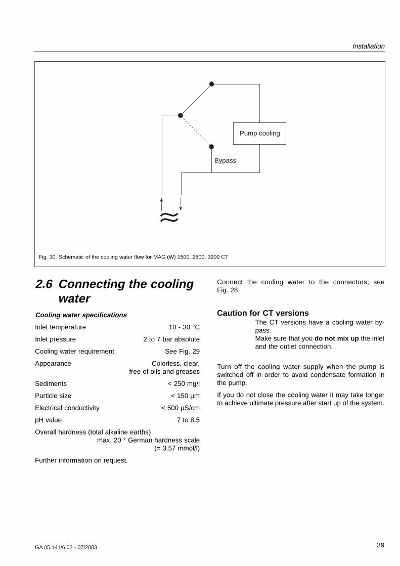
Fig. 30 Schematic of the cooling water flow for MAG (W) 1500, 2800, 3200 CT
2.6 Connecting the coolingwater
Cooling water specifications
Inlet temperature 10 - 30 °C
Inlet pressure 2 to 7 bar absolute
Cooling water requirement See Fig. 29
Appearance Colorless, clear, free of oils and greases
Sediments < 250 mg/l
Particle size < 150 µm
Electrical conductivity < 500 µS/cm
pH value 7 to 8.5
Overall hardness (total alkaline earths) max. 20 ° German hardness scale
(= 3.57 mmol/l)
Further information on request.
Connect the cooling water to the connectors; see Fig. 28.
Caution for CT versionsThe CT versions have a cooling water by-pass.Make sure that you do not mix up the inletand the outlet connection.
Turn off the cooling water supply when the pump isswitched off in order to avoid condensate formation inthe pump.
If you do not close the cooling water it may take longerto achieve ultimate pressure after start up of the system.
Installation
40 GA 05.141/6.02 - 07/2003
2.7 Connecting the purge gasPlease contact Leybold for assistance in making thedecision as to which media can be pumped with or with-out purge gas.
In processes which require purge gas the pump will haveto be vented, when it is switched off, through the purgegas port.
Suited are all gases,
• which will not cause corrosion or pitting in aluminiumand steel and
• which in connection with process deposits in thepump will not cause corrosion or sticking.
For venting and as the purge gas we recommend inertgases like nitrogen or argon. The temperature of thesegases should be between 5 °C and 80 °C , max. relativehumidity should not exceed 10 ppm.
In individual cases and after consultation also dry, filte-red, oil-free air or filtered ambient air may be used (filtermesh < 1µm).
Change the filters after some time, at least annually.
Different venting methods are described in Chapter 3.1.
MAG (W) 1500, MAG W 2800, MAG W 3200The MAG is equipped with a purge gas and ventingvalve. It is controlled by the MAG.DRIVEdigital. Additionalmonitoring with a flow controller is not necessary.
The purge gas and vent valve
• regulates the flow of purge gas, at supply pressuresof between 1.5 and 6.0 bar (absolute), to the pump,keeping pressure at a constant value and
• provides for safe pump venting.
The flow of purge gas into the pump keeps aggressive orcorrosive media and dust from entering the motor andbearing area.
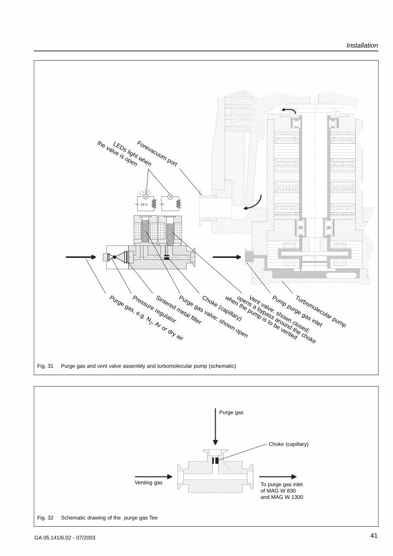
Refer to Figure 31 for details on the design and functionof the purge gas and vent valve assembly.
Attach the purge gas hose to the nipple and secure witha hose clamp.
Set purge gas pressure for a value of 1.5 to 6.0 bar,absolute.
Use in the purge gas supply system only valves whichcan handle both the low purge gas flow and the muchgreater venting gas flow.
CautionPurge gas inlet pressure exceeding 10bar can damage or destroy the purgegas and vent valve.
With no voltage applied the purge gas and vent valve isclosed.
The purge gas and vent valve will be open when swit-ching on the MAG.DRIVEdigital. The red LED at the purgegas valve lights.
Technical data
Purge gas pressure, absolute 1.5 to 6.0 bar
Purge gas Nitrogen or similar
Max. moisture content 10 ppm
Purge gas flow 36 sccm ± 5 sccm(36 sccm = 0.6 mbar·l/s)
Vent gas flow 4800±10% sccm
Leak rate < 10-7 mbar·l/s
Connection: VCR Nut 1/4“
MAG W 830, W 1300, W 2200The MAG has a purge gas inlet VCR nut 1/4“ or DN 16KF. The required purge gas flow is 36 sccm ± 5 sccm.
The pump needs an external purge gas control.
The optional purge gas Tee allows the throttled inlet ofpurge and venting gas. A purge gas pressure of 1.5 bar(abs.) will provide the required flow of 36 sccm ± 5 sccm.
The Tee and the the purge vent valve can be mounted tothe MAG W 830 and W 1300.
WarningMonitor the purge gas supply continuously.Insufficient purge gas flow can result in:• Process gases entering the motor and
bearing area of the MAG• Process gases escaping from the purge
gas inlet• Humidity entering the pump.
Installation
41GA 05.141/6.02 - 07/2003
lower magneticbearing
Motor
upper magneticbearing
Sensor PVW 2,4
lower magneticbearing
24 V
Turbomolecular pump
Pump purge gas inlet
Vent valve: shown closed;
opens a bypass around the choke
when the pump is to be vented
Choke (capillary)
Purge gas valve: shown open
Sintered metal filter
Pressure regulator
Purge gas, e.g. N2 , Ar or dry air
Forevacuum port
LEDs light when
the valve is open
Fig. 31 Purge gas and vent valve assembly and turbomolecular pump (schematic)
Fig. 32 Schematic drawing of the purge gas Tee
Venting gas
Purge gas
To purge gas inletof MAG W 830 and MAG W 1300
Choke (capillary)
WarningUnauthorized opening of the convertervoids the warranty.Hazardous voltages are present inside theconverter. Death or severe injury can occurif you come into contact with these hazar-dous voltages. Before opening the conver-ter, isolate the converter from the line supp-ly, and lock the switch so that it cannot beaccidentally switched on again.In addition the pump has to stand stillbecause it works as generator as long as itrotates, and the pump cables have to bedisconnected.
Installation instructions to maintain EMCThe MAG.DRIVEdigital complies with the ElectromagneticCompatibility (EMC) Directives of the EC. In order tomaintain this the following installation instructions mustbe observed:
• To connect the pump to the converter the prescribedLeybold cables must be used.
• The connection cables to the analog interface (con-trol plug X14) and to the serial interface (connectorX7) must be shielded. The shields must be connectedto the metal housings of the SUB-D-connector andSUB-D-socket.
2.8.1 Power supply connection X19The converter is ready to be connected to line supplyvoltages between 200-240 V 50/60 Hz. The connectionis established using the power cable supplied, which isinserted at connector X19 at the rear of the converter.
CautionThe converter will be damaged if it is ope-rated with the incorrect supply voltage.
2.8.2 Pump connection
WarningTo avoid contact with hazardous voltages incase of malfunction the pump must beconnected to PE.
Connect the converter (X20) to the motor and magneticbearing connection of the pump (X23) and the PK com-munication connection (X24) using the DRIVE/ BEA-RING cable.
Installation
42 GA 05.141/6.02 - 07/2003
2.8 Installing the MAG.DRIVEdigital
The converter can be installed in a 19” cabinet. It is 1/2of 19“ wide and has 3 height units. For easier installati-on we offer an installation frame; see Section 1.7. If youuse this installation frame, remove the converter’s rub-ber feet when installing the converter.
CautionIn order to guarantee sufficient cooling,there must be a minimum clearance of 1height unit (44.2 mm) at the bottom and 1height unit at the top. During operation thetemperature of the ambient air must notexceed 45 °C.
WarningThe pump may be operated only with a sui-table frequency converter and a suit-able connector cable.Peak voltages of up to 130 V may be pre-sent at the connector line between the fre-quency converter and the pump; mains vol-tage is present at the heater.Route all cables so as to protect them fromdamage.
The protection rating for the connectors is IP 30.
Do not expose the pump, the frequency converter or theconnections to dripping water.
Install 16 A fuses for the converter.
When connecting the frequency converter to a polypha-se network between two phases, provide additionalexternal fuse protection for both phases (fuse ampera-ge: 16 A).
WarningOnly adequately trained electrical/electronicpersonnel may connect-up the equipmentin accordance with valid IEC (international),EN (European) and/or national guidelines,or under their management and supervisi-on.
WarningThe connecting cables between the conver-ter and pump may only be inserted or remo-ved when the pump is switched off andstands still after the run-down procedureand the converter is isolated from the linesupply.
Do not switch on frequency converter untilall cables have been connected properly.
Installation
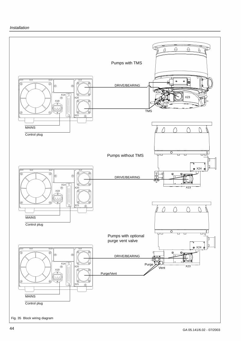
Connect the converter (X21) to the TMS connection(X30) using the TMS cable.
Also refer to Fig. 35.
Make sure that you have fixed all cables properly.
2.8.3 Control plug X14
Emergency off
Make sure that pins 47 and 48 are connected via a jum-per if you don’t connect an emergency off switch.
A plug for the control plug X14 with a jumper connectedbetween pins 47 and 48 is included in the standard spe-cification.
Description of the Emergency Off connection
Pins 47 and 48 of control plug X14 make it possible todisable the output stage of the frequency converter viathe hardware. The power flow to the motor is then inter-rupted.
The two pins must be connected to each other to ensu-re proper operation.
If the two pins are to be monitored by the system control,a floating (dry) contact must be available on the systemside; load carrying capacity: 42 VDC, 100 mA.
The contact used and the connecting cable must be pro-tected against line supply voltage through double or rein-forced insulation such that no hazardous contact linesupply voltage can be applied to pins 47 and 48 in theevent of a fault.
43GA 05.141/6.02 - 07/2003
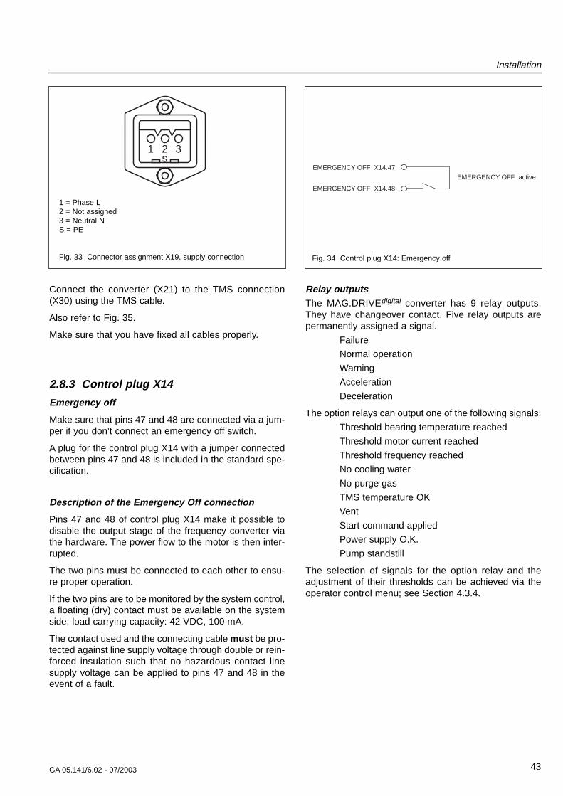
1 2 3s
1 = Phase L2 = Not assigned3 = Neutral NS = PE
Fig. 33 Connector assignment X19, supply connection
EMERGENCY OFF X14.47
EMERGENCY OFF X14.48
EMERGENCY OFF active
Fig. 34 Control plug X14: Emergency off
Relay outputsThe MAG.DRIVEdigital converter has 9 relay outputs.They have changeover contact. Five relay outputs arepermanently assigned a signal.
Failure
Normal operation
Warning
Acceleration
Deceleration
The option relays can output one of the following signals:
Threshold bearing temperature reached
Threshold motor current reached
Threshold frequency reached
No cooling water
No purge gas
TMS temperature OK
Vent
Start command applied
Power supply O.K.
Pump standstill
The selection of signals for the option relay and theadjustment of their thresholds can be achieved via theoperator control menu; see Section 4.3.4.
Installation
44 GA 05.141/6.02 - 07/2003
Fig. 35 Block wiring diagram
TMS
DRIVE/BEARING
X24
X23
X30
X19
X14X20
X21
MAINS
Control plug
DRIVE/BEARING
X24
X23
Pumps with TMS
Pumps without TMS
X19
X14X20
X21
MAINS
Control plug
X19
X14X20
X21
MAINS
Control plug
DRIVE/BEARING
X24
X23
Pumps with optionalpurge vent valve
Purge/Vent
PurgeVent
GA 05.141/6.02 - 07/2003
Installation
45
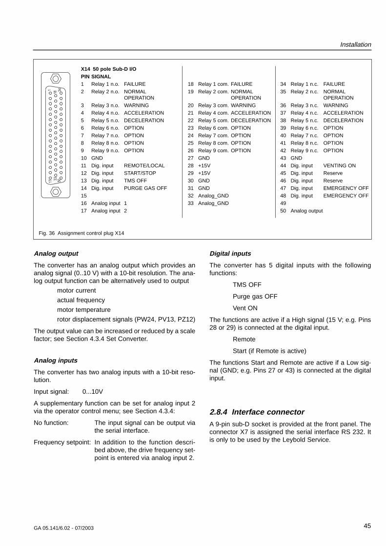
Fig. 36 Assignment control plug X14
X14 50 pole Sub-D I/OPIN SIGNAL1 Relay 1 n.o. FAILURE
2 Relay 2 n.o. NORMALOPERATION
3 Relay 3 n.o. WARNING
4 Relay 4 n.o. ACCELERATION
5 Relay 5 n.o. DECELERATION
6 Relay 6 n.o. OPTION
7 Relay 7 n.o. OPTION
8 Relay 8 n.o. OPTION
9 Relay 9 n.o. OPTION
10 GND
11 Dig. input REMOTE/LOCAL
12 Dig. input START/STOP
13 Dig. input TMS OFF
14 Dig. input PURGE GAS OFF
15
16 Analog input 1
17 Analog input 2
18 Relay 1 com. FAILURE
19 Relay 2 com. NORMALOPERATION
20 Relay 3 com. WARNING
21 Relay 4 com. ACCELERATION
22 Relay 5 com. DECELERATION
23 Relay 6 com. OPTION
24 Relay 7 com. OPTION
25 Relay 8 com. OPTION
26 Relay 9 com. OPTION
27 GND
28 +15V
29 +15V
30 GND
31 GND
32 Analog_GND
33 Analog_GND
34 Relay 1 n.c. FAILURE
35 Relay 2 n.c. NORMALOPERATION
36 Relay 3 n.c. WARNING
37 Relay 4 n.c. ACCELERATION
38 Relay 5 n.c. DECELERATION
39 Relay 6 n.c. OPTION
40 Relay 7 n.c. OPTION
41 Relay 8 n.c. OPTION
42 Relay 9 n.c. OPTION
43 GND
44 Dig. input VENTING ON
45 Dig. input Reserve
46 Dig. input Reserve
47 Dig. input EMERGENCY OFF
48 Dig. input EMERGENCY OFF
49
50 Analog output
Analog output
The converter has an analog output which provides ananalog signal (0..10 V) with a 10-bit resolution. The ana-log output function can be alternatively used to output
motor current
actual frequency
motor temperature
rotor displacement signals (PW24, PV13, PZ12)
The output value can be increased or reduced by a scalefactor; see Section 4.3.4 Set Converter.
Analog inputs
The converter has two analog inputs with a 10-bit reso-lution.
Input signal: 0...10V
A supplementary function can be set for analog input 2via the operator control menu; see Section 4.3.4:
No function: The input signal can be output viathe serial interface.
Frequency setpoint: In addition to the function descri-bed above, the drive frequency set-point is entered via analog input 2.
Digital inputs
The converter has 5 digital inputs with the followingfunctions:
TMS OFF
Purge gas OFF
Vent ON
The functions are active if a High signal (15 V; e.g. Pins28 or 29) is connected at the digital input.
Remote
Start (if Remote is active)
The functions Start and Remote are active if a Low sig-nal (GND; e.g. Pins 27 or 43) is connected at the digitalinput.
2.8.4 Interface connectorA 9-pin sub-D socket is provided at the front panel. Theconnector X7 is assigned the serial interface RS 232. Itis only to be used by the Leybold Service.
Installation
46 GA 05.141/6.02 - 07/2003
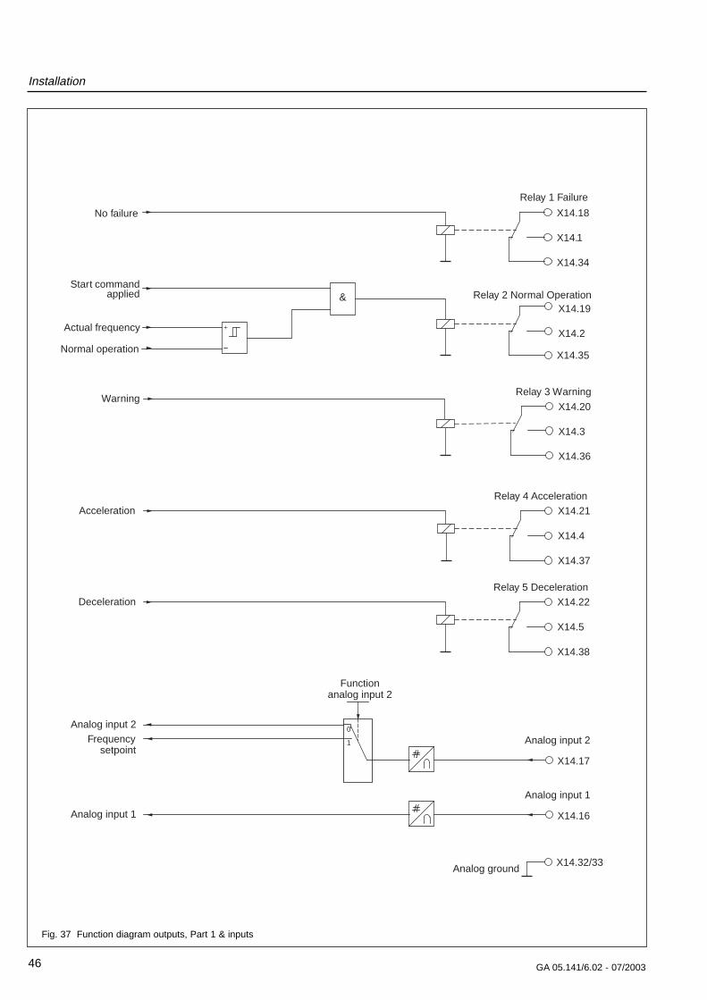
X14.17
0
1 Analog input 2
Relay 4 AccelerationAcceleration X14.21
X14.4
X14.37
Relay 5 DecelerationDeceleration X14.22
X14.5
X14.38
Functionanalog input 2
Analog input 2Frequency
setpoint
X14.16
Analog input 1
Analog input 1
X14.32/33Analog ground
X14.35
&X14.19
X14.2Actual frequency
Normal operation
Start commandapplied Relay 2 Normal Operation
WarningX14.20
X14.3
X14.36
Relay 3 Warning
X14.18
X14.1
X14.34
No failure
Relay 1 Failure
Fig. 37 Function diagram outputs, Part 1 & inputs
Installation
47GA 05.141/6.02 - 07/2003
0
X14.23/24/25/26
X14.6/7/8/9
X14.39/40/41/42
X X14.50
X14.32/33
X14.28/29+15 V
8
Venting
Threshold
0
1
2
4
5
6
Rotor displacementPVW13peakPVW24peak
PZ12peak
Current limiting80 mA
1
2
3
4
5
6
7
9
Pump standstillStart command
Power supply o.k.
Threshold
Threshold
Motor- or bearing-temperature
Motor current
Act. frequency
Functionsignal relay
Functionanalog output
Analog output
Analog ground
Scale
No cooling water
No purge gas
TMS temp. o.k.
Relay 6/7/8/9 Option
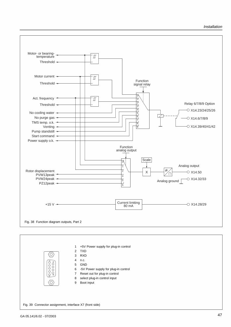
Fig. 38 Function diagram outputs, Part 2
15
69
1 +5V Power supply for plug-in control
2 TXD
3 RXD
4 n.c.
5 GND
6 -5V Power supply for plug-in control
7 Reset out for plug-in control
8 select plug-in control input
9 Boot input
Fig. 39 Connector assignment, interface X7 (front side)
3 Operation3.1 General operation rulesThe magnetic bearing in the MAG are immune to wear.In addition to the magnetic bearings, the MAG is equip-ped with touch-down bearings which protect the rotoragainst mechanical contact with the stator if the pump issubjected to external shock loading or when the pump isswitched off. These touch-down bearings have a limitedservice life. Please observe the following in order toobtain maximum service life.
• Avoid shock and vibrations when the pump is run-ning. Shocks perpendicular to the rotation axis areparticularly harmful. If the pump appears to be run-ning in the mechanical bearings continuously it isswitched off.
• Do not suddenly expose the MAG to an already eva-cuated vacuum chamber. The pressure surge maycause the rotor to make contact with the touch-downbearings. This will cause increased wear.
• Do not disconnect the MAG and MAG.DRIVEdigital
while they are operating. If MAG and MAG.DRIVEdi-
gital have been disconnected accidently re-connectthem.
• Do not stop the MAG with the mains. Use the STOPkey or a stop command. Switching off the mains whilethe pump is running will wear out the touch down bearings.
The pump may make noise during the run-up and run-down phases. This has neither an influence on the pumpnor on the process.
WarningMonitor the purge gas supply continuously.Insufficient purge gas flow can result in:• Process gases entering the motor and
bearing area of the MAG• Process gases escaping from the purge
gas inlet• Humidity entering the pump.
Refer to Section 2.7.
WarningThe pump will be hot during operation. Burnhazard!
Venting
As to suitable gases, see Chapter 2.7.
Venting Method
The pump must be vented via the purge gas and ven-ting valve or the vent port when shutting the pumpdown.
When additionally venting the vacuum chamber, the ven-ting function of the purge gas and venting valve must beopened before opening the chamber valve. This willensure the presence of a higher pressure in the magne-tic bearings compared to the remaining vacuum area.This will prevent particles, dust or aggressive gases frombeing forced into the not yet vented motor chamber ofthe pump.
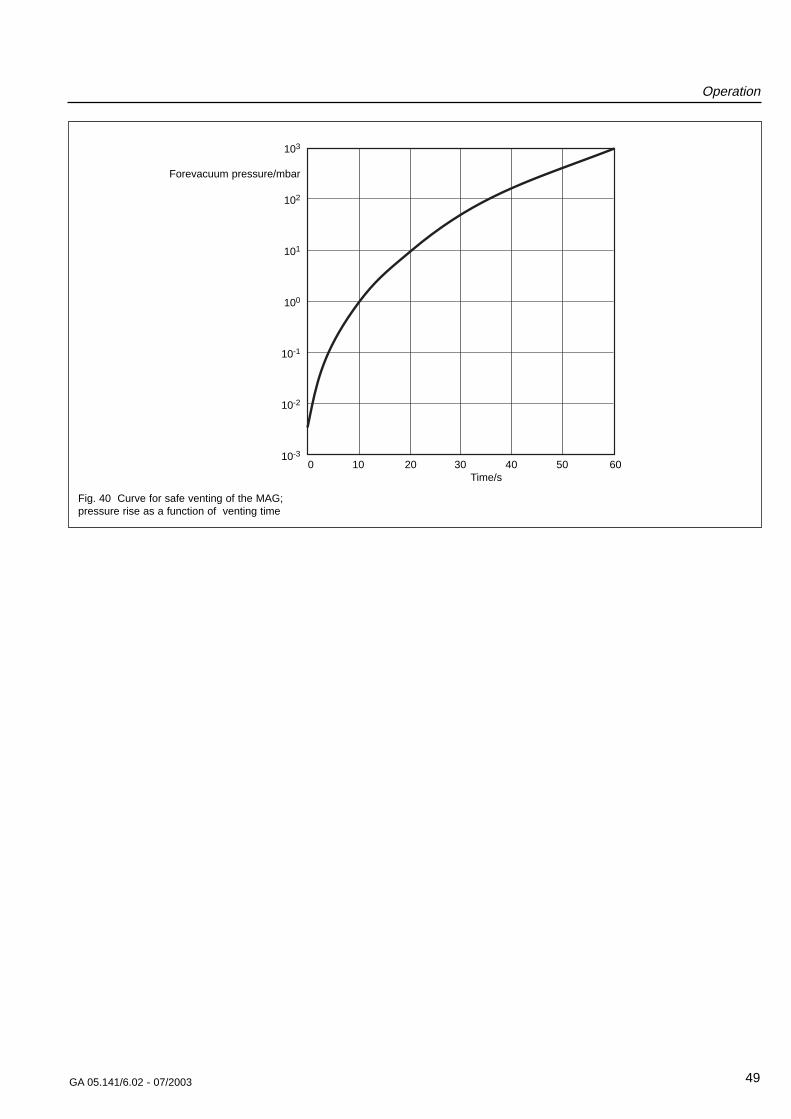
Speed of the pressure rise
All turbomolecular pumps may be vented at full speed.However, the pressure must not increase faster thanspecified through the pressure rise curve.
The pump must be vented significantly slower whenthere is the risk of particles entering into the pump fromthe process. During venting, the flow must be of thelaminar type in both the vacuum chamber and the turbo-molecular pump.
The pump must not be vented to pressures aboveatmospheric pressure.
Operation
48 GA 05.141/6.02 - 07/2003
Operation
49GA 05.141/6.02 - 07/2003
103
Forevacuum pressure/mbar
102
101
100
10-1
10-2
10-3
Fig. 40 Curve for safe venting of the MAG;pressure rise as a function of venting time
0 10 20 30 40 50 60Time/s
Operation
50 GA 05.141/6.02 - 07/2003
3.2 Operation with theSTART and STOP keys
Switching on
• Switch on the MAG.DRIVEdigital.
The MAIN LED lights green.
If the pump has the optional TMS (including e.g. the redheater band) the heater will be activated. The setpointtemperature will be reached within 30 - 60 minutesdepending on cooling water temperature and flow.
In case of corresponding connection the backing pumpwill be activated when switching on the MAG.DRIVEdigi-
tal.
• Open the purge gas supply. With a converter withdefault settings the pump’s purge gas valve is open.
• Open the cooling water supply.
• Press the START key.
The pump runs-up. The STATUS LED is slowly flashinggreen. When the STATUS LED is lit permanently greenthe pump is in normal operation.
Switching off
• Press the STOP key.
The STATUS LED is fast flashing green. When the STA-TUS LED is off the pump has come to a standstill.
• Close the cooling water supply when the pump isswitched off in order to avoid condensate formation inthe pump.
The backing pump may be switched off once the MAGhas stopped.
If the MAG has been used for pumping corrosive gasesit should be purged with dry nitrogen for one hour befo-re switching off. During down times of the system takecare that neither ambient air nor cleaning agents enterthe pump.
After a failure has occured and has been removed, ack-nowledge the failure message by pressing the STOPkey.
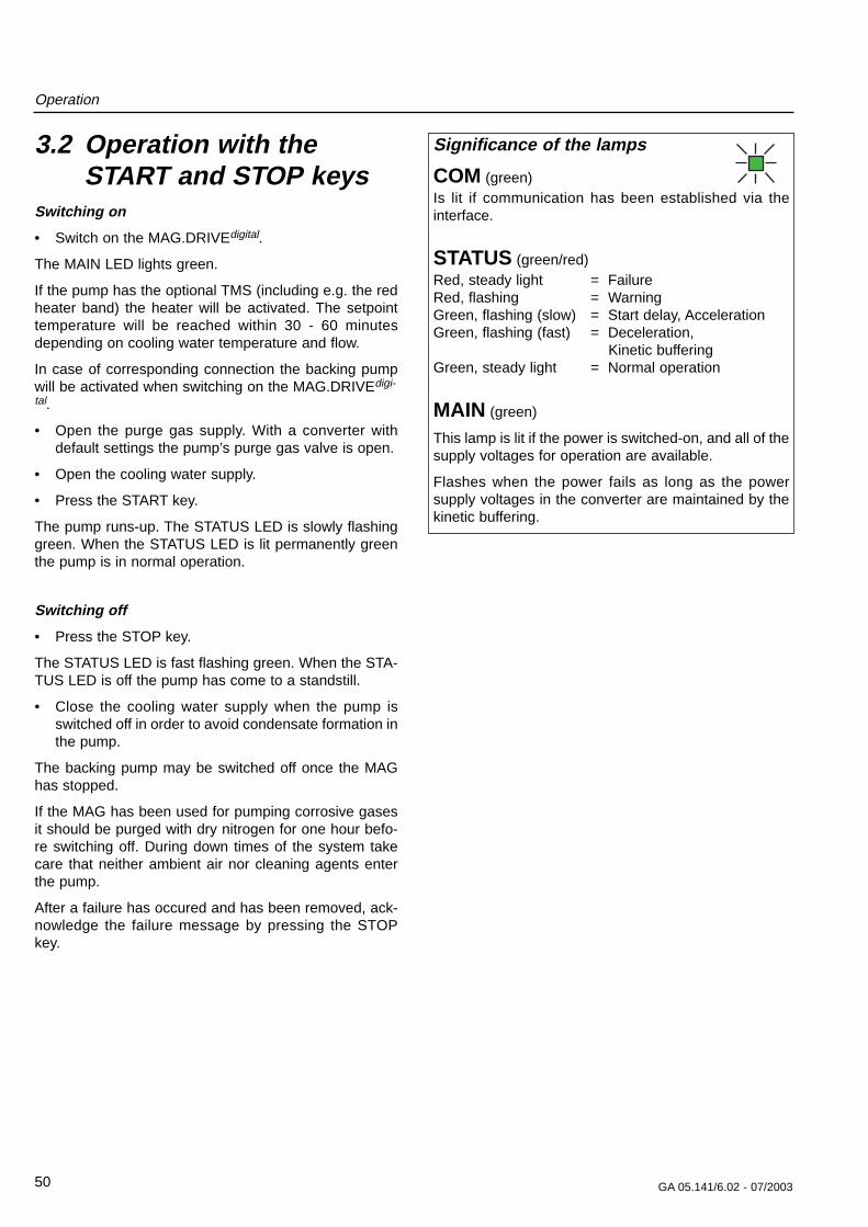
Significance of the lamps
COM (green)Is lit if communication has been established via theinterface.
STATUS (green/red)Red, steady light = FailureRed, flashing = WarningGreen, flashing (slow) = Start delay, AccelerationGreen, flashing (fast) = Deceleration,
Kinetic bufferingGreen, steady light = Normal operation
MAIN (green)
This lamp is lit if the power is switched-on, and all of thesupply voltages for operation are available.
Flashes when the power fails as long as the powersupply voltages in the converter are maintained by thekinetic buffering.
GA 05.141/6.02 - 07/2003
Operation
51
Remote
Start
Masse
X1.1
X1.2
X1.3
Switch closed: STARTSwitch open: STOP
Remote X14.11
Start X14.12
Ground X14.10
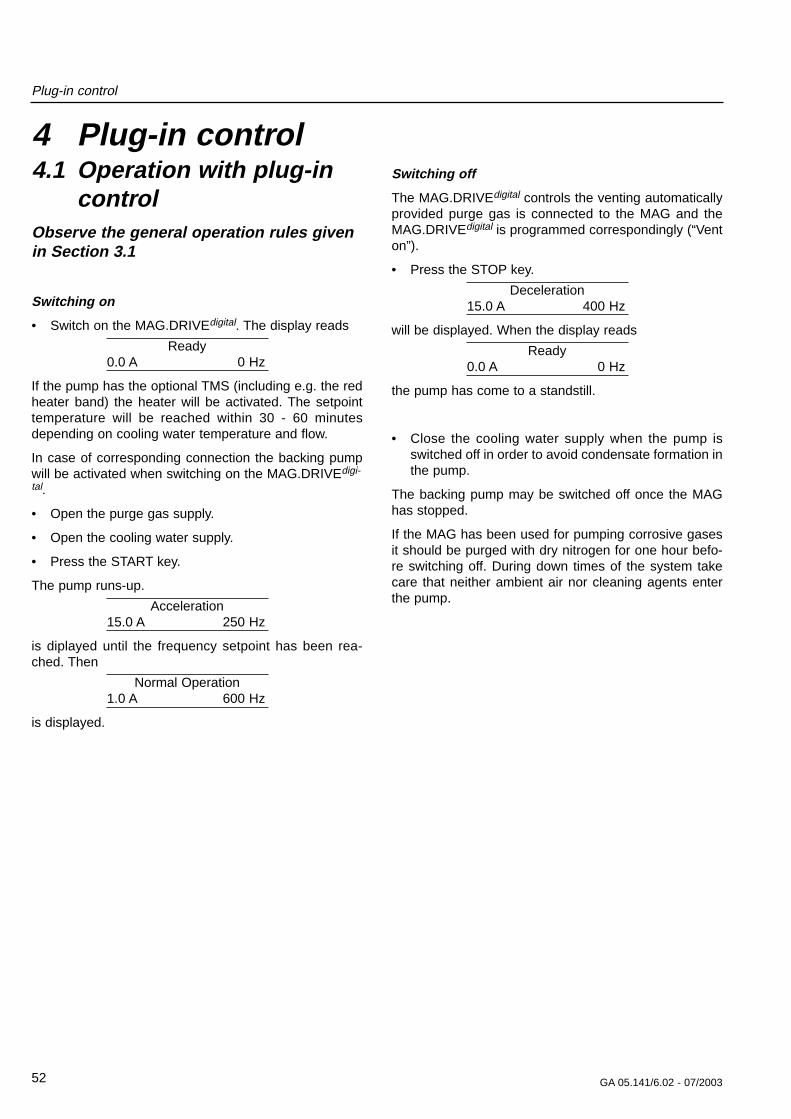
Fig. 42 Connecting-up example remote control
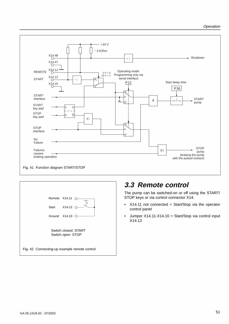
3.3 Remote controlThe pump can be switched-on or off using the START/STOP keys or via control connector X14.
• X14.11 not connected = Start/Stop via the operatorcontrol panel
• Jumper X14.11-X14.10 = Start/Stop via control inputX14.12
0
1
P12
0
1
2
S
R
Q
Q
&
-1
s
0
1
2
≥1
≥1
START
REMOTE
+15 V
X14.11
X14.12
X14.10
P36
= 1X14.48
X14.47
Shutdown
Start delay time
STARTpump
STOPpump
(braking the pumpwith the pulsed resistor)
STARTkey pad
STOPkey pad
STOPinterface
STARTinterface
NoFailure
Operating mode:Programming only via
serial interface
Failurescausesbraking operation
0 V = 015 V = 1
~ 3 kOhm
m
Fig. 41 Function diagram START/STOP
Plug-in control
4 Plug-in control4.1 Operation with plug-in
controlObserve the general operation rules givenin Section 3.1
Switching on
• Switch on the MAG.DRIVEdigital. The display reads
Ready0.0 A 0 Hz
If the pump has the optional TMS (including e.g. the redheater band) the heater will be activated. The setpointtemperature will be reached within 30 - 60 minutesdepending on cooling water temperature and flow.
In case of corresponding connection the backing pumpwill be activated when switching on the MAG.DRIVEdigi-
tal.
• Open the purge gas supply.
• Open the cooling water supply.
• Press the START key.
The pump runs-up.
Acceleration15.0 A 250 Hz
is diplayed until the frequency setpoint has been rea-ched. Then
Normal Operation1.0 A 600 Hz
is displayed.
Switching off
The MAG.DRIVEdigital controls the venting automaticallyprovided purge gas is connected to the MAG and theMAG.DRIVEdigital is programmed correspondingly (“Venton”).
• Press the STOP key.
Deceleration15.0 A 400 Hz
will be displayed. When the display reads
Ready0.0 A 0 Hz
the pump has come to a standstill.
• Close the cooling water supply when the pump isswitched off in order to avoid condensate formation inthe pump.
The backing pump may be switched off once the MAGhas stopped.
If the MAG has been used for pumping corrosive gasesit should be purged with dry nitrogen for one hour befo-re switching off. During down times of the system takecare that neither ambient air nor cleaning agents enterthe pump.
52 GA 05.141/6.02 - 07/2003
Plug-in control
53GA 05.141/6.02 - 07/2003
Start Stop
Esc Mon Prog Enter
+_
Acceleration
14.5A 254Hz HOK
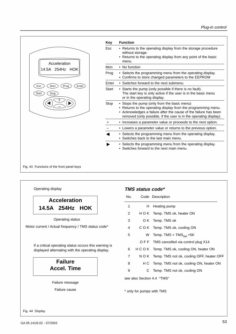
Key Function
Esc • Returns to the operating display from the storage procedurewithout storage.
• Returns to the operating display from any point of the basicmenu.
Mon • No function
Prog • Selects the programming menu from the operating display.• Confirms to store changed parameters to the EEPROM
Enter • Switches forward to the next submenu
Start • Starts the pump (only possible if there is no fault).The start key is only active if the user is in the basic menu or in the operating display.
Stop • Stops the pump (only from the basic menu)• Returns to the operating display from the programming menu.• Acknowledges a failure after the cause of the failure has been
removed (only possible, if the user is in the operating display).
+ • Increases a parameter value or proceeds to the next option.
– • Lowers a parameter value or returns to the previous option.
< • Selects the programming menu from the operating display.• Switches back to the last main menu.
> • Selects the programming menu from the operating display.• Switches forward to the next main menu.
Fig. 43 Functions of the front panel keys
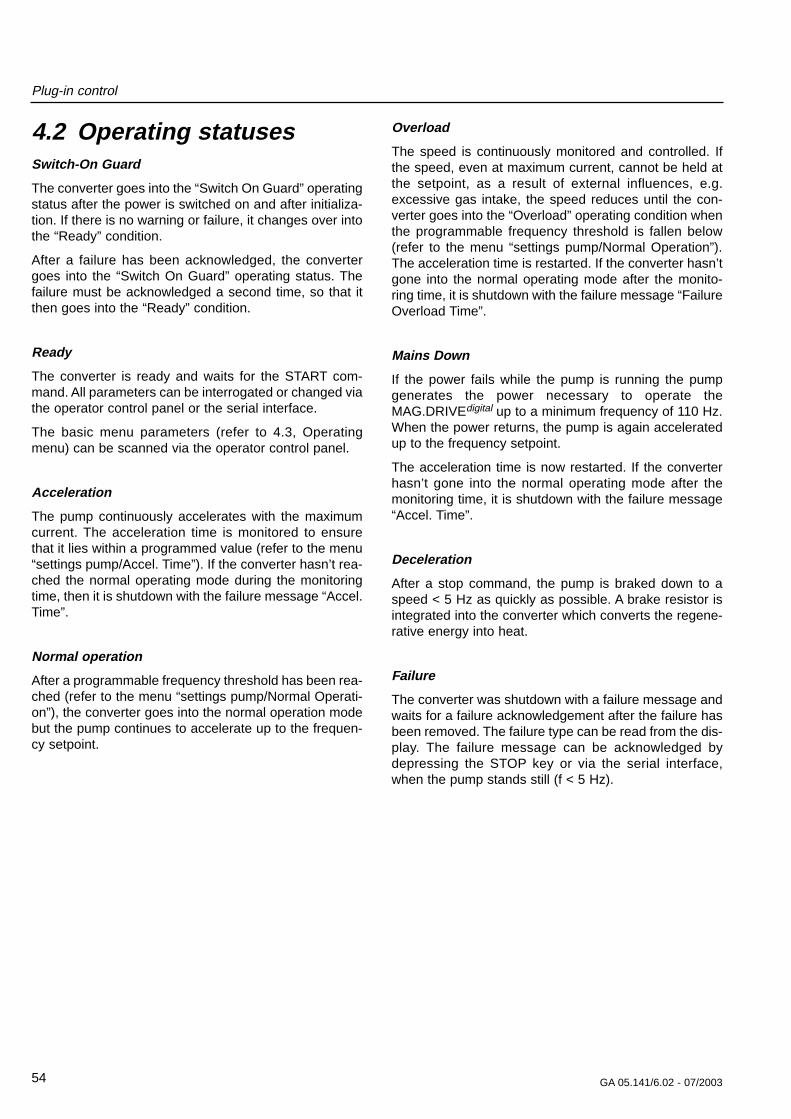
Acceleration14.5A 254Hz HOK
Operating display
Operating status
Motor current / Actual frequency / TMS status code*
If a critical operating status occurs this warning isdisplayed alternating with the operating display.
FailureAccel. Time
Failure message
Failure cause
TMS status code*No. Code Description
——————————————————————————1 H Heating pump
2 H O K Temp. TMS ok, heater ON
3 O K Temp. TMS ok
4 C O K Temp. TMS ok, cooling ON
5 W Temp. TMS > TMSSet +5K
O F F TMS cancelled via control plug X14
6 H C O K Temp. TMS ok, cooling ON, heater ON
7 N O K Temp. TMS not ok, cooling OFF, heater OFF
8 H C Temp. TMS not ok, cooling ON, heater ON
9 C Temp. TMS not ok, cooling ON
see also Section 4.4 “TMS”
* only for pumps with TMS
Fig. 44 Display
Plug-in control
54 GA 05.141/6.02 - 07/2003
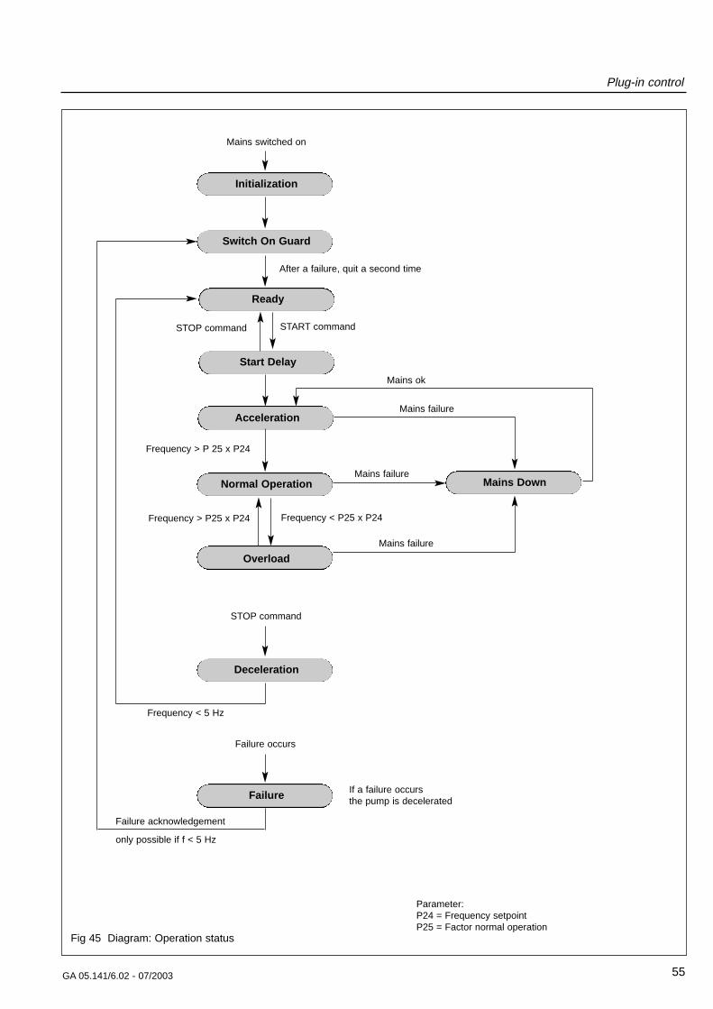
4.2 Operating statusesSwitch-On Guard
The converter goes into the “Switch On Guard” operatingstatus after the power is switched on and after initializa-tion. If there is no warning or failure, it changes over intothe “Ready” condition.
After a failure has been acknowledged, the convertergoes into the “Switch On Guard” operating status. Thefailure must be acknowledged a second time, so that itthen goes into the “Ready” condition.
Ready
The converter is ready and waits for the START com-mand. All parameters can be interrogated or changed viathe operator control panel or the serial interface.
The basic menu parameters (refer to 4.3, Operatingmenu) can be scanned via the operator control panel.
Acceleration
The pump continuously accelerates with the maximumcurrent. The acceleration time is monitored to ensurethat it lies within a programmed value (refer to the menu“settings pump/Accel. Time”). If the converter hasn’t rea-ched the normal operating mode during the monitoringtime, then it is shutdown with the failure message “Accel.Time”.
Normal operation
After a programmable frequency threshold has been rea-ched (refer to the menu “settings pump/Normal Operati-on”), the converter goes into the normal operation modebut the pump continues to accelerate up to the frequen-cy setpoint.
Overload
The speed is continuously monitored and controlled. Ifthe speed, even at maximum current, cannot be held atthe setpoint, as a result of external influences, e.g.excessive gas intake, the speed reduces until the con-verter goes into the “Overload” operating condition whenthe programmable frequency threshold is fallen below(refer to the menu “settings pump/Normal Operation”).The acceleration time is restarted. If the converter hasn’tgone into the normal operating mode after the monito-ring time, it is shutdown with the failure message “FailureOverload Time”.
Mains Down
If the power fails while the pump is running the pumpgenerates the power necessary to operate theMAG.DRIVEdigital up to a minimum frequency of 110 Hz.When the power returns, the pump is again acceleratedup to the frequency setpoint.
The acceleration time is now restarted. If the converterhasn’t gone into the normal operating mode after themonitoring time, it is shutdown with the failure message“Accel. Time”.
Deceleration
After a stop command, the pump is braked down to aspeed < 5 Hz as quickly as possible. A brake resistor isintegrated into the converter which converts the regene-rative energy into heat.
Failure
The converter was shutdown with a failure message andwaits for a failure acknowledgement after the failure hasbeen removed. The failure type can be read from the dis-play. The failure message can be acknowledged bydepressing the STOP key or via the serial interface,when the pump stands still (f < 5 Hz).
Plug-in control
55GA 05.141/6.02 - 07/2003
Mains switched on
Initialization
Switch On Guard
Acceleration
Normal Operation Mains Down
Overload
Deceleration
Failure
After a failure, quit a second time
START command
Mains ok
Frequency > P 25 x P24
Mains failure
Mains failure
Frequency > P25 x P24 Frequency < P25 x P24
Mains failure
STOP command
If a failure occurs the pump is decelerated
Frequency < 5 Hz
Failure occurs
Failure acknowledgement
only possible if f < 5 Hz
Ready
Start Delay
STOP command
Parameter:P24 = Frequency setpointP25 = Factor normal operation
Fig 45 Diagram: Operation status
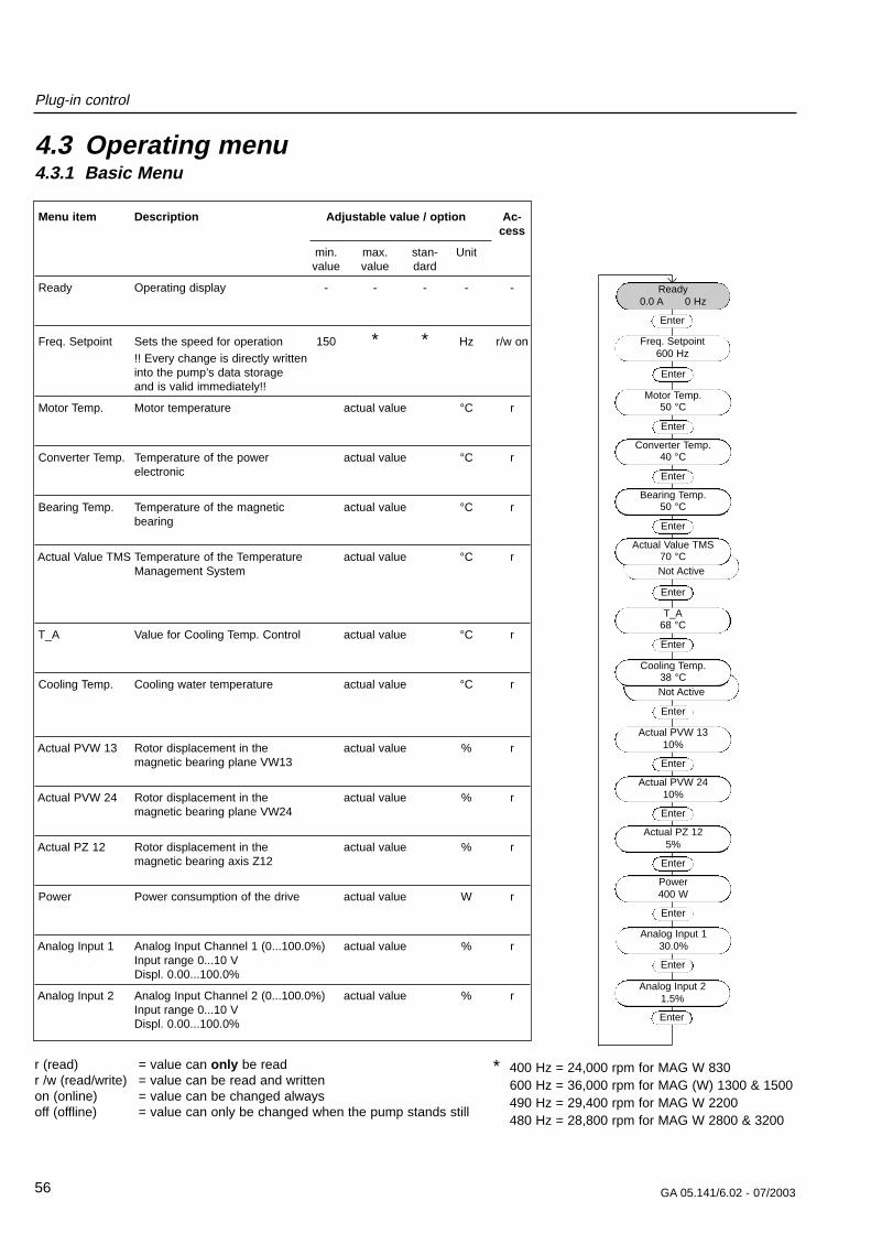
4.3.1 Basic Menu
Menu item Description Adjustable value / option Ac-cess
min. max. stan- Unitvalue value dard
Ready Operating display - - - - -
Freq. Setpoint Sets the speed for operation 150 * * Hz r/w on!! Every change is directly writteninto the pump’s data storageand is valid immediately!!
Motor Temp. Motor temperature actual value °C r
Converter Temp. Temperature of the power actual value °C relectronic
Bearing Temp. Temperature of the magnetic actual value °C rbearing
Actual Value TMS Temperature of the Temperature actual value °C rManagement System
T_A Value for Cooling Temp. Control actual value °C r
Cooling Temp. Cooling water temperature actual value °C r
Actual PVW 13 Rotor displacement in the actual value % rmagnetic bearing plane VW13
Actual PVW 24 Rotor displacement in the actual value % rmagnetic bearing plane VW24
Actual PZ 12 Rotor displacement in the actual value % rmagnetic bearing axis Z12
Power Power consumption of the drive actual value W r
Analog Input 1 Analog Input Channel 1 (0...100.0%) actual value % rInput range 0...10 VDispl. 0.00...100.0%
Analog Input 2 Analog Input Channel 2 (0...100.0%) actual value % rInput range 0...10 VDispl. 0.00...100.0%
Plug-in control
56 GA 05.141/6.02 - 07/2003
Ready0.0 A 0 Hz
Enter
Enter
Motor Temp.50 °C
Enter
Converter Temp.40 °C
Enter
Bearing Temp.50 °C
Enter
Actual PVW 1310%
Enter
Actual PVW 2410%
Enter
Actual PZ 125%
Enter
Power400 W
Enter
Not Active
Actual Value TMS70 °C
Not Active
Cooling Temp.38 °C
Enter
r (read) = value can only be readr /w (read/write) = value can be read and writtenon (online) = value can be changed alwaysoff (offline) = value can only be changed when the pump stands still
4.3 Operating menu
Analog Input 130.0%
Enter
T_A68 °C
Enter
Enter
Analog Input 21.5%
Enter
Freq. Setpoint600 Hz
* 400 Hz = 24,000 rpm for MAG W 830600 Hz = 36,000 rpm for MAG (W) 1300 & 1500490 Hz = 29,400 rpm for MAG W 2200480 Hz = 28,800 rpm for MAG W 2800 & 3200
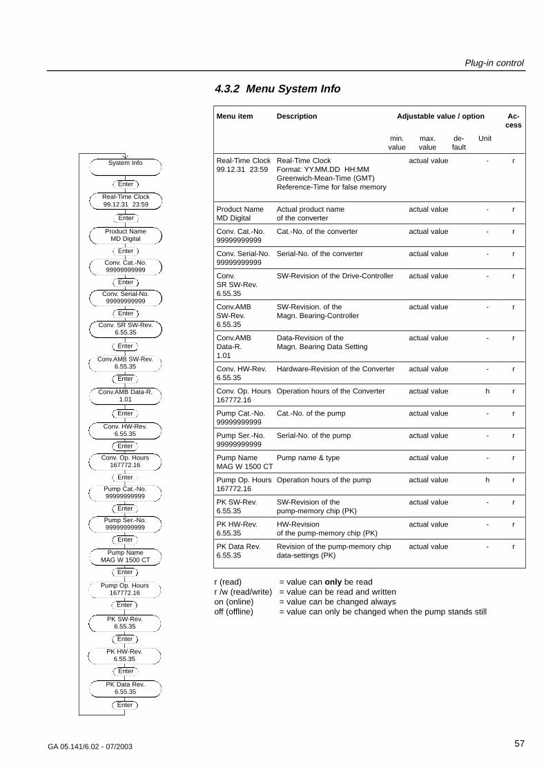
Plug-in control
57GA 05.141/6.02 - 07/2003
4.3.2 Menu System Info
Menu item Description Adjustable value / option Ac-cess
min. max. de- Unitvalue value fault
Real-Time Clock Real-Time Clock actual value - r99.12.31 23:59 Format: YY.MM.DD HH:MM
Greenwich-Mean-Time (GMT)Reference-Time for false memory
Product Name Actual product name actual value - rMD Digital of the converter
Conv. Cat.-No. Cat.-No. of the converter actual value - r99999999999
Conv. Serial-No. Serial-No. of the converter actual value - r99999999999
Conv. SW-Revision of the Drive-Controller actual value - rSR SW-Rev.6.55.35
Conv.AMB SW-Revision. of the actual value - rSW-Rev. Magn. Bearing-Controller6.55.35
Conv.AMB Data-Revision of the actual value - rData-R. Magn. Bearing Data Setting1.01
Conv. HW-Rev. Hardware-Revision of the Converter actual value - r6.55.35
Conv. Op. Hours Operation hours of the Converter actual value h r167772.16
Pump Cat.-No. Cat.-No. of the pump actual value - r99999999999
Pump Ser.-No. Serial-No. of the pump actual value - r99999999999
Pump Name Pump name & type actual value - rMAG W 1500 CT
Pump Op. Hours Operation hours of the pump actual value h r167772.16
PK SW-Rev. SW-Revision of the actual value - r6.55.35 pump-memory chip (PK)
PK HW-Rev. HW-Revision actual value - r6.55.35 of the pump-memory chip (PK)
PK Data Rev. Revision of the pump-memory chip actual value - r6.55.35 data-settings (PK)
r (read) = value can only be readr /w (read/write) = value can be read and writtenon (online) = value can be changed alwaysoff (offline) = value can only be changed when the pump stands still
Enter
Product NameMD Digital
Enter
Conv. Cat.-No.99999999999
Enter
Conv. Serial-No.99999999999
Enter
Conv. HW-Rev.6.55.35
Enter
Conv. Op. Hours167772.16
Enter
Pump Cat.-No.99999999999
Enter
Pump Ser.-No.99999999999
Enter
Conv. SR SW-Rev.6.55.35
Conv.AMB Data-R.1.01
Enter
Pump NameMAG W 1500 CT
Enter
Conv.AMB SW-Rev.6.55.35
Enter
Enter
Pump Op. Hours167772.16
Enter
System Info
PK SW-Rev.6.55.35
Enter
PK HW-Rev.6.55.35
Enter
PK Data Rev.6.55.35
Enter
Enter
Real-Time Clock99.12.31 23:59
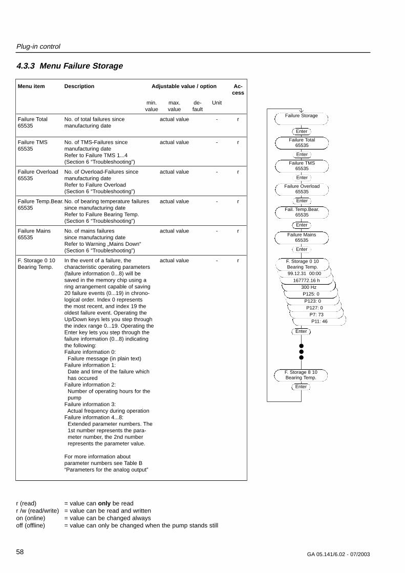
P11: 46P7: 73
P127: 0
Plug-in control
58 GA 05.141/6.02 - 07/2003
4.3.3 Menu Failure Storage
Menu item Description Adjustable value / option Ac-cess
min. max. de- Unitvalue value fault
Failure Total No. of total failures since actual value - r65535 manufacturing date
Failure TMS No. of TMS-Failures since actual value - r65535 manufacturing date
Refer to Failure TMS 1...4(Section 6 “Troubleshooting”)
Failure Overload No. of Overload-Failures since actual value - r65535 manufacturing date
Refer to Failure Overload(Section 6 “Troubleshooting”)
Failure Temp.Bear. No. of bearing temperature failures actual value - r65535 since manufacturing date
Refer to Failure Bearing Temp.(Section 6 “Troubleshooting”)
Failure Mains No. of mains failures actual value - r65535 since manufacturing date
Refer to Warning „Mains Down“(Section 6 “Troubleshooting”)
F. Storage 0 10 In the event of a failure, the actual value - rBearing Temp. characteristic operating parameters
(failure information 0...8) will be saved in the memory chip using a ring arrangement capable of saving 20 failure events (0...19) in chrono-logical order. Index 0 represents the most recent, and index 19 the oldest failure event. Operating theUp/Down keys lets you step throughthe index range 0...19. Operating the Enter key lets you step through the failure information (0...8) indicating the following:Failure information 0:
Failure message (in plain text)Failure information 1:
Date and time of the failure whichhas occured
Failure information 2:Number of operating hours for the pump
Failure information 3:Actual frequency during operation
Failure information 4...8:Extended parameter numbers. The 1st number represents the para-meter number, the 2nd number represents the parameter value.
For more information about parameter numbers see Table B “Parameters for the analog output”
r (read) = value can only be readr /w (read/write) = value can be read and writtenon (online) = value can be changed alwaysoff (offline) = value can only be changed when the pump stands still
Enter
Failure Total65535
Enter
Failure TMS65535
Enter
Failure Overload65535
Enter
Fail. Temp.Bear.65535
Failure Mains65535
Enter
Failure Storage
Enter
P123: 0
P125: 0300 Hz
167772.16 h
99.12.31 00:00
F. Storage 0 10Bearing Temp.
Enter
F. Storage 8 10Bearing Temp.
Enter
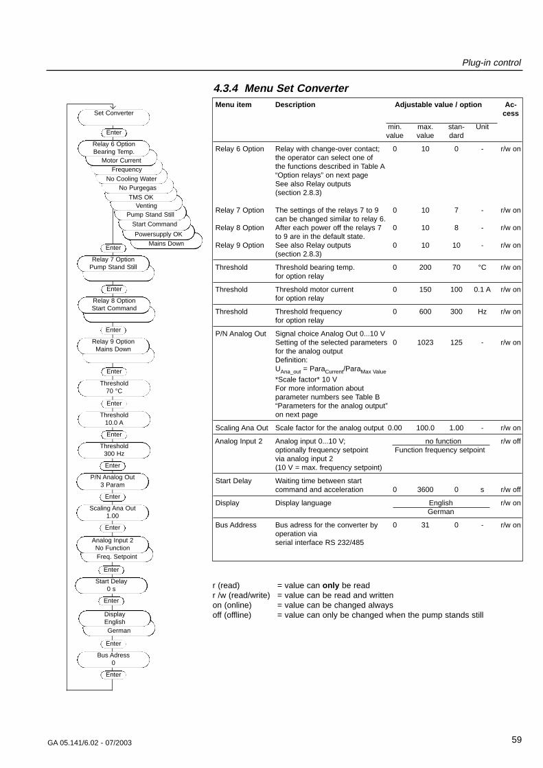
Mains Down
Powersupply OK
Start Command
Plug-in control
59GA 05.141/6.02 - 07/2003
r (read) = value can only be readr /w (read/write) = value can be read and writtenon (online) = value can be changed alwaysoff (offline) = value can only be changed when the pump stands still
4.3.4 Menu Set ConverterMenu item Description Adjustable value / option Ac-
cess
min. max. stan- Unitvalue value dard
Relay 6 Option Relay with change-over contact; 0 10 0 - r/w onthe operator can select one ofthe functions described in Table A“Option relays” on next pageSee also Relay outputs (section 2.8.3)
Relay 7 Option The settings of the relays 7 to 9 0 10 7 - r/w oncan be changed similar to relay 6.
Relay 8 Option After each power off the relays 7 0 10 8 - r/w onto 9 are in the default state.
Relay 9 Option See also Relay outputs 0 10 10 - r/w on(section 2.8.3)
Threshold Threshold bearing temp. 0 200 70 °C r/w onfor option relay
Threshold Threshold motor current 0 150 100 0.1 A r/w onfor option relay
Threshold Threshold frequency 0 600 300 Hz r/w onfor option relay
P/N Analog Out Signal choice Analog Out 0...10 VSetting of the selected parameters 0 1023 125 - r/w onfor the analog outputDefinition: UAna_out = ParaCurrent/ParaMax Value
*Scale factor* 10 VFor more information about parameter numbers see Table B“Parameters for the analog output” on next page
Scaling Ana Out Scale factor for the analog output 0.00 100.0 1.00 - r/w on
Analog Input 2 Analog input 0...10 V; no function r/w offoptionally frequency setpoint Function frequency setpointvia analog input 2(10 V = max. frequency setpoint)
Start Delay Waiting time between start command and acceleration 0 3600 0 s r/w off
Display Display language English r/w onGerman
Bus Address Bus adress for the converter by 0 31 0 - r/w onoperation via serial interface RS 232/485
Freq. Setpoint
Pump Stand Still
Enter
Threshold70 °C
Enter
Threshold10.0 A
Enter
Threshold300 Hz
Enter
P/N Analog Out3 Param
Enter
Scaling Ana Out1.00
Enter
Start Delay0 s
Enter
Enter
Relay 8 OptionStart Command
Enter
Relay 9 OptionMains Down
Enter
Relay 7 OptionPump Stand Still
VentingTMS OK
No PurgegasNo Cooling Water
Frequency
Set Converter
Enter
Motor Current
Relay 6 OptionBearing Temp.
Enter
Analog Input 2No Function
German
Enter
Bus Adress0
Enter
DisplayEnglish
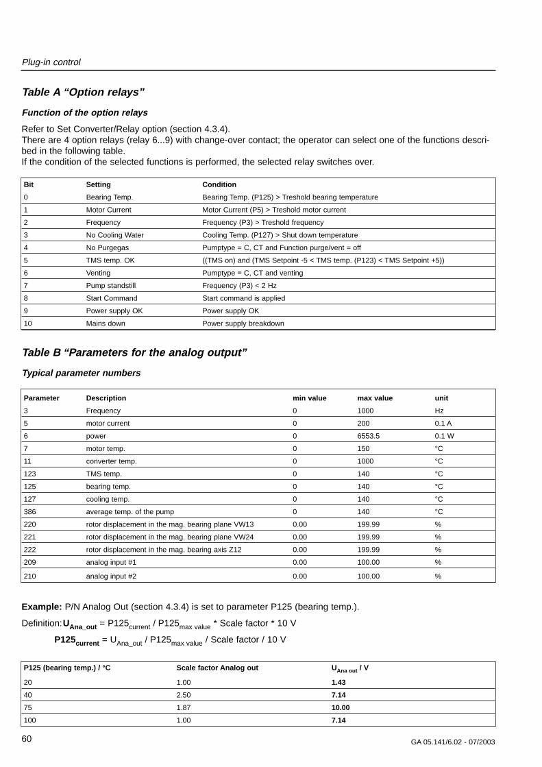
Plug-in control
60 GA 05.141/6.02 - 07/2003
Table A “Option relays”
Function of the option relays
Refer to Set Converter/Relay option (section 4.3.4). There are 4 option relays (relay 6...9) with change-over contact; the operator can select one of the functions descri-bed in the following table.If the condition of the selected functions is performed, the selected relay switches over.
Bit Setting Condition
0 Bearing Temp. Bearing Temp. (P125) > Treshold bearing temperature
1 Motor Current Motor Current (P5) > Treshold motor current
2 Frequency Frequency (P3) > Treshold frequency
3 No Cooling Water Cooling Temp. (P127) > Shut down temperature
4 No Purgegas Pumptype = C, CT and Function purge/vent = off
5 TMS temp. OK ((TMS on) and (TMS Setpoint -5 < TMS temp. (P123) < TMS Setpoint +5))
6 Venting Pumptype = C, CT and venting
7 Pump standstill Frequency (P3) < 2 Hz
8 Start Command Start command is applied
9 Power supply OK Power supply OK
10 Mains down Power supply breakdown
Table B “Parameters for the analog output”
Typical parameter numbers
Parameter Description min value max value unit
3 Frequency 0 1000 Hz
5 motor current 0 200 0.1 A
6 power 0 6553.5 0.1 W
7 motor temp. 0 150 °C
11 converter temp. 0 1000 °C
123 TMS temp. 0 140 °C
125 bearing temp. 0 140 °C
127 cooling temp. 0 140 °C
386 average temp. of the pump 0 140 °C
220 rotor displacement in the mag. bearing plane VW13 0.00 199.99 %
221 rotor displacement in the mag. bearing plane VW24 0.00 199.99 %
222 rotor displacement in the mag. bearing axis Z12 0.00 199.99 %
209 analog input #1 0.00 100.00 %
210 analog input #2 0.00 100.00 %
Example: P/N Analog Out (section 4.3.4) is set to parameter P125 (bearing temp.).
Definition:UAna_out = P125current / P125max value * Scale factor * 10 V
P125current = UAna_out / P125max value / Scale factor / 10 V
P125 (bearing temp.) / °C Scale factor Analog out UAna out / V
20 1.00 1.43
40 2.50 7.14
75 1.87 10.00
100 1.00 7.14
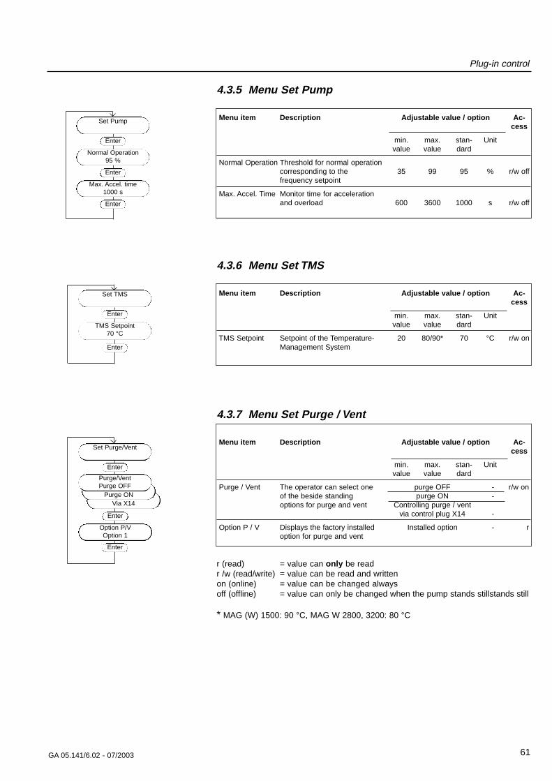
Plug-in control
61GA 05.141/6.02 - 07/2003
4.3.5 Menu Set Pump
Menu item Description Adjustable value / option Ac-cess
min. max. stan- Unitvalue value dard
Normal Operation Threshold for normal operation corresponding to the 35 99 95 % r/w offfrequency setpoint
Max. Accel. Time Monitor time for acceleration and overload 600 3600 1000 s r/w off
4.3.6 Menu Set TMS
Menu item Description Adjustable value / option Ac-cess
min. max. stan- Unitvalue value dard
TMS Setpoint Setpoint of the Temperature- 20 80/90* 70 °C r/w onManagement System
4.3.7 Menu Set Purge / Vent
Menu item Description Adjustable value / option Ac-cess
min. max. stan- Unitvalue value dard
Purge / Vent The operator can select one purge OFF - r/w onof the beside standing purge ON -options for purge and vent Controlling purge / vent
via control plug X14 -
Option P / V Displays the factory installed Installed option - roption for purge and vent
r (read) = value can only be readr /w (read/write) = value can be read and writtenon (online) = value can be changed alwaysoff (offline) = value can only be changed when the pump stands stillstands still
* MAG (W) 1500: 90 °C, MAG W 2800, 3200: 80 °C
Set Pump
Enter
Normal Operation95 %
Enter
Max. Accel. time1000 s
Enter
Set TMS
Enter
TMS Setpoint70 °C
Enter
Via X14Purge ON
Set Purge/Vent
Enter
Purge/VentPurge OFF
Enter
Option P/VOption 1
Enter
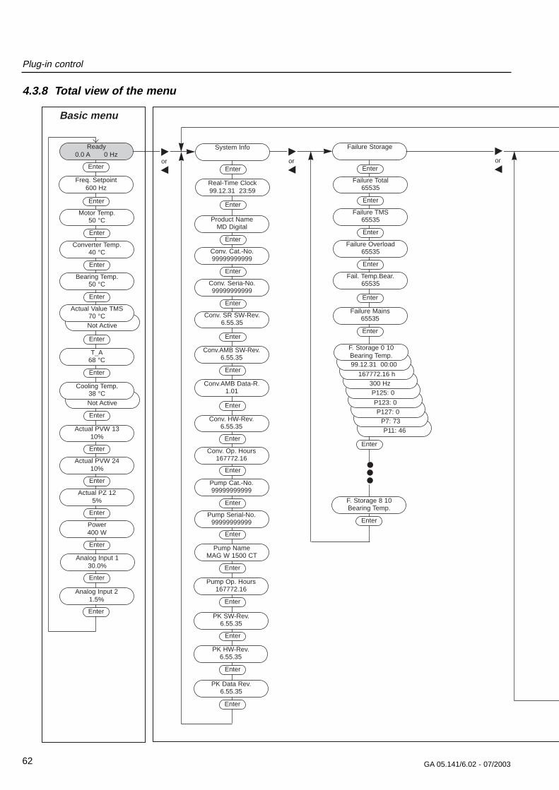
Plug-in control
62 GA 05.141/6.02 - 07/2003
Basic menu
or
Ready0.0 A 0 Hz
Enter
Enter
Motor Temp.50 °C
Enter
Converter Temp.40 °C
Enter
Bearing Temp.50 °C
Enter
Actual PVW 1310%
Enter
Actual PVW 2410%
Enter
Actual PZ 125%
Enter
Power400 W
Enter
Not Active
Actual Value TMS70 °C
Not Active
Cooling Temp.38 °C
Enter
Analog Input 130.0%
Enter
T_A68 °C
Enter
Enter
Analog Input 21.5%
Enter
Freq. Setpoint600 Hz
Enter
Product NameMD Digital
Enter
Conv. Cat.-No.99999999999
Enter
Conv. Seria-No.99999999999
Enter
Conv. HW-Rev.6.55.35
Enter
Conv. Op. Hours167772.16
Enter
Pump Cat.-No.99999999999
Enter
Pump Serial-No.99999999999
Enter
Conv. SR SW-Rev.6.55.35
Conv.AMB Data-R.1.01
Enter
Pump NameMAG W 1500 CT
Enter
Conv.AMB SW-Rev.6.55.35
Enter
Enter
Pump Op. Hours167772.16
Enter
System Info
PK SW-Rev.6.55.35
Enter
PK HW-Rev.6.55.35
Enter
PK Data Rev.6.55.35
Enter
P11: 46P7: 73
P127: 0
Enter
Failure Total65535
Enter
Failure TMS65535
Enter
Failure Overload65535
Enter
Fail. Temp.Bear.65535
Failure Mains65535
Enter
Failure Storage
Enter
P123: 0
P125: 0300 Hz
167772.16 h
99.12.31 00:00
F. Storage 0 10Bearing Temp.
Enter
F. Storage 8 10Bearing Temp.
Enter
Enter
Real-Time Clock99.12.31 23:59
or or
4.3.8 Total view of the menu
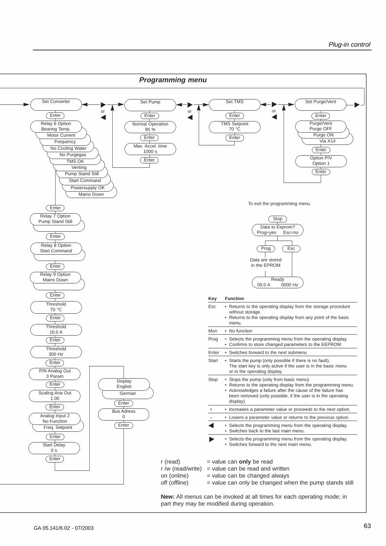
Plug-in control
63GA 05.141/6.02 - 07/2003
Programming menu
Stop
Data to Eeprom?Prog=yes Esc=no
Prog
Ready00.0 A 0000 Hz
Esc
Data are storedin the EPROM
To exit the programming menu
Via X14Purge ON
Set Pump
Enter
Normal Operation95 %
Enter
Max. Accel. time1000 s
Enter
Set TMS
Enter
TMS Setpoint70 °C
Enter
Set Purge/Vent
Enter
Purge/VentPurge OFF
Enter
Option P/VOption 1
Enter
or
Key Function
Esc • Returns to the operating display from the storage procedurewithout storage.
• Returns to the operating display from any point of the basicmenu.
Mon • No function
Prog • Selects the programming menu from the operating display.• Confirms to store changed parameters to the EEPROM
Enter • Switches forward to the next submenu
Start • Starts the pump (only possible if there is no fault).The start key is only active if the user is in the basic menu or in the operating display.
Stop • Stops the pump (only from basic menu)• Returns to the operating display from the programming menu.• Acknowledges a failure after the cause of the failure has
been removed (only possible, if the user is in the operating display).
+ • Increases a parameter value or proceeds to the next option.
– • Lowers a parameter value or returns to the previous option.
< • Selects the programming menu from the operating display.• Switches back to the last main menu.
> • Selects the programming menu from the operating display.• Switches forward to the next main menu.
or or
Mains Down
Powersupply OK
Start Command
Freq. Setpoint
Pump Stand Still
Enter
Threshold70 °C
Enter
Threshold10.0 A
Enter
Threshold300 Hz
Enter
P/N Analog Out3 Param
Enter
Scaling Ana Out1.00
Enter
Start Delay0 s
Enter
Enter
Relay 8 OptionStart Command
Enter
Relay 9 OptionMains Down
Enter
Relay 7 OptionPump Stand Still
VentingTMS OK
No PurgegasNo Cooling Water
Frequency
Set Converter
Enter
Motor Current
Relay 6 OptionBearing Temp.
Enter
Analog Input 2No Function
German
Enter
Bus Adress0
Enter
DisplayEnglish
r (read) = value can only be readr /w (read/write) = value can be read and writtenon (online) = value can be changed alwaysoff (offline) = value can only be changed when the pump stands still
New: All menus can be invoked at all times for each operating mode; inpart they may be modified during operation.
Plug-in control
64 GA 05.141/6.02 - 07/2003
4.4 TemperatureManagement System
Function description
The TMS is only in function, when a MAG CT version isconnected. The heater will be activated when the mainsis switched on. The TMS controls the heating and watercooling to maintain the pump at the specified setpointtemperature.
In order to maintain an almost homogeneous temperatu-re distribution in the pump the system is equipped withseveral temperature sensors. The measured values ofthese sensors are used to determine two temperaturesfor the TMS: TTMS and TA. Both temperatures are usedto switch on and off the heater and the cooling watervalve.
Switching points
Heater OFF → ON TTMS < Tset – 1 K
Heater ON → OFF TTMS > Tset + 1 K
Cooling OFF → ON TA > Tset + 2 K
Cooling ON → OFF TA < Tset + 1 K
TMS ok Tset – 5 K ≤ TTMS ≤ Tset + 5 K
Warning TMS TTMS > Tset + 5 K
Settings
The temperature (TMS) setpoint can be programmed viathe front panel keys at every time.
Principally the factory presetting will be used. The settingis saved in the pump’s memory chip. Before changingany setpoint value request Leybold!
For the setting refer to 4.3.6 Operating menu, Set TMS.
Heat up
The setpoint temperature will be reached within 30 to 60minutes depending on cooling and environmental condi-tions. For temperature sensitive applications observe thecooling water specifications (refer to Section 1.6 and2.6).
CautionIn order to guarantee correct temperaturesetting of the pump it is required to providethe cooling water within the envelopedescribed in Section 2.6.
TMS status code
The TMS status code is displayed on the operation dis-play.
No. Code Description——————————————————————————
1 H Heating pump
2 H O K Temp. TMS ok, heater ON
3 O K Temp. TMS ok
4 C O K Temp. TMS ok, cooling ON
5 W Temp. TMS > TMSSet +5K
O F F TMS cancelled via control plug X14
6 H C O K Temp. TMS ok, cooling ON, heater ON
7 N O K Temp. TMS not ok, cooling OFF, heater OFF
8 H C Temp. TMS not ok, cooling ON, heater ON
9 C Temp. TMS not ok, cooling ON
Actual temperature
The actual temperature is displayed on the operatingdisplay (refer to 4.3.1 Operating menu, Basic menu)
Signal TMS OK
If the actual TMS temperature lies in the range ±5K fromthe setpoint temperature, the TMS OK signal can be out-put via the option relay. The option relay must be pro-grammed for this function (refer to Section 2.8.3 Controlplug X14, Relay outputs)
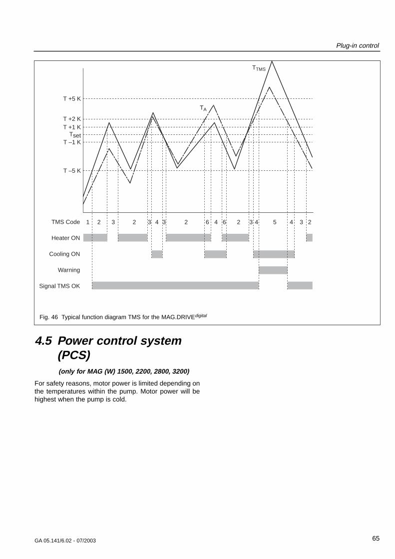
Plug-in control
65GA 05.141/6.02 - 07/2003
1 2 3 2 3 4 3 2 6 4 6 2 3 4 5 4 3 2
T +5 K
T –5 K
T –1 KTset
T +1 KT +2 K
TMS Code
Heater ON
Cooling ON
Warning
Signal TMS OK
TTMS
TA
Fig. 46 Typical function diagram TMS for the MAG.DRIVEdigital
4.5 Power control system(PCS)(only for MAG (W) 1500, 2200, 2800, 3200)
For safety reasons, motor power is limited depending onthe temperatures within the pump. Motor power will behighest when the pump is cold.
5 Maintenance5.1 CleaningIf required clean the turbomolecular pump and the fre-quency converter of dust with a dry cloth.
5.2 Changing the rotorThe rotor has to be changed
- after 40,000 hours of operation or
- after 5000 starts/stops.
WarningDue to high-speed and temperature, theservice life of the rotor is limited.
If the rotor is changed too late, it may bedestroyed. Thus in the flange mounts highforces and torque conditions can occur.
The mounting screws for the pump maybe torn off. When using clamped flangeconnections at the housing or with compo-nents above the housing, sudden twisting ofthe entire pump can be experienced.
The pump’s operating hours are displayed at the fre-quency converter (see Sectiont 4.3.2 ).
Only the Leybold service can change the rotor.
5.3 Changing the touchdown bearings
Wear occurs at the touch-down bearings when hardshocks have to be supported.
Maintenance is also required after removing the bearingcable during operation of the pump. Under these condi-tions the rotor can not be controlled by the magnet bea-ring and the pump will have a full run down on the touchdown bearing.
Only the Leybold service can change the touch-downbearings.
5.4 Cleaning the frequencyconverter internally
Depending on the installation site the converter maycollect grime (dust, moisture) on the inside. Such conta-mination may lead to malfunctions, overheating or shortcircuits. Therefore the converter must be cleaned after 5years.
Only the Leybold service can clean the converter inter-nally.
5.5 Removing the pumpfrom the system
MAG which have been used in semiconductor processesare contaminated by semiconductor process gases.Most of these gases form acids when exposed to moistair which causes serious corrosion damage to the pump.
To prevent corrosion damage during storage and ship-ping, use the seal kit.
Failure to seal a contaminated MAG voids the warranty.
The seal kit contains the following
- dry cartridge,
- plastic cap for forevacuum connection flange,
- plastic adhesive film and
- aluminum cover and screws for the high-vacuumconnection flange.
CautionFor safety reasons we recommend to use ametal seal kit (order no. 200 07 901; seeFig. 48) for shipping of contaminatedpumps. For storage of contaminated pumpsduring tool maintenance a standard seal kitcan be used.
GA 05.141/6.02 - 07/2003
Maintenance
66
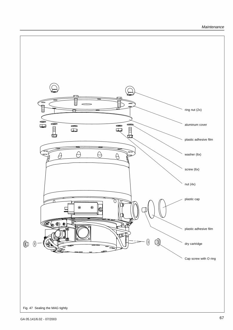
Maintenance
67GA 05.141/6.02 - 07/2003
Fig. 47 Sealing the MAG tightly
ring nut (2x)
aluminum cover
plastic adhesive film
washer (6x)
screw (6x)
nut (4x)
plastic cap
plastic adhesive film
dry cartridge
Cap screw with O ring
Maintenance
Proceed as follows to seal the turbomolecular pumpimmediately after removing it from your process.
Purge the pump for two hours with the backing pumprunning. This helps to remove a large quantity of the pro-cess gases from the pump. We recommend purging thepump via the intake flange and the purge valve withapprox. 200 sccm.
Press the STOP button at the MAG.DRIVEdigital and waituntil the pump has come to a standstill.
Afterwards turn the mains switch to the “0” position.
The cables between the MAG and MAG.DRIVEdigital maybe disconnected only after the MAG has come to a fullstillstand and the mains is switched off.
WarningWhen the pump has been pumping hazar-dous gases, ensure that proper safety pre-cautions are taken before opening the inta-ke or exhaust connections.
Use gloves or protective clothing to avoidskin contact with toxic or highly corrosivesubstances. Work under a fume hood ifavailable.
Disconnect the cables from the pump.
Disconnect the cooling water lines. Remaining coolingwater may flow out. Protect all parts below.
Remove all bolts but 2 which hold the intake flange. The2 remaining bolts must be directly opposite.
Disconnect the forevacuum line.
Support the pump with a lift-truck at the base plate andremove the 2 remaining bolts.
Clean the intake and forevacuum connection flange asnecessary for good adhesion of tape.
Place the dry cartridge into the forevacuum port. Don’tuse loose crystals.
Firmly seal all ports with plastic adhesive film.
Cover the forevacuum connection port with its plasticcap.
Seal the high-vacuum connection flange with the coverand the screws.
Pack the pump so that it may not be damaged duringtransportation. Particularly protect the flanges, the coo-ling water connectors and the current feedthrough.
Only for MAG with DN 160 or 200As the plastic adhesive film is too large for the high-vacu-um connection flange slit it a little bit at the screw holes.
5.6 Service at Leybold’sIf you send a pump to Leybold indicate whether thepump is free of substances damaging to health orwhether it is contaminated. If it is contaminated also indi-cate the nature of hazard. To do so, you must use a pre-printed form which we shall send to you upon request.
A copy of this form is printed at the end of the OperatingInstructions: “Declaration of Contamination of VacuumEquipment and Components”. Another suitable form isavailable from the Leybold homepage: http://www.leyboldvac.de under the headline “customerservice”.
Either fasten this form at the pump or simply enclose it tothe pump.
Don’t pack the form with the pump into the PE bag.
This declaration of contamination is necessary to comp-ly with legal requirements and to protect our staff.
Leybold must return any pump without a declaration ofcontamination to the sender’s address.
68 GA 05.141/6.02 - 07/2003
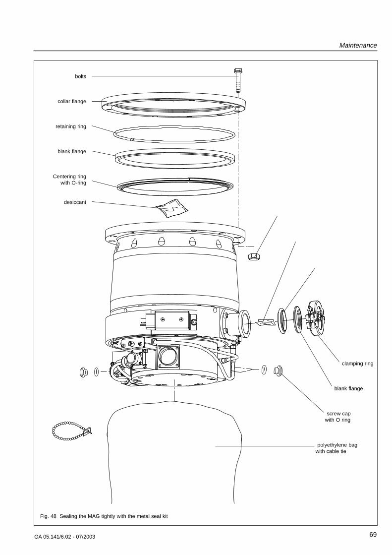
Maintenance
69GA 05.141/6.02 - 07/2003
Fig. 48 Sealing the MAG tightly with the metal seal kit
bolts
collar flange
retaining ring
blank flange
Centering ring with O-ring
desiccant
clamping ring
blank flange
screw cap with O ring
polyethylene bag with cable tie
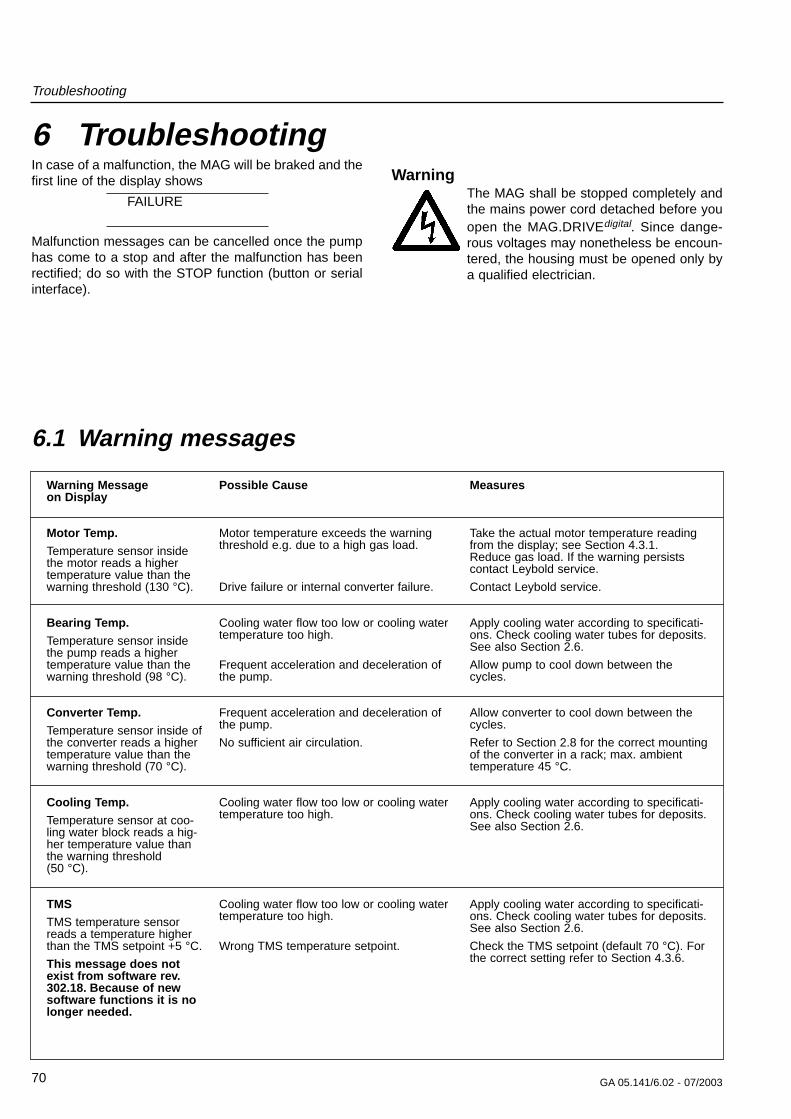
Troubleshooting
70 GA 05.141/6.02 - 07/2003
Warning Message on Display
Motor Temp.
Temperature sensor insidethe motor reads a highertemperature value than thewarning threshold (130 °C).
Bearing Temp.
Temperature sensor insidethe pump reads a highertemperature value than thewarning threshold (98 °C).
Converter Temp.
Temperature sensor inside ofthe converter reads a highertemperature value than thewarning threshold (70 °C).
Cooling Temp.
Temperature sensor at coo-ling water block reads a hig-her temperature value thanthe warning threshold (50 °C).
TMS
TMS temperature sensorreads a temperature higherthan the TMS setpoint +5 °C.
This message does notexist from software rev.302.18. Because of newsoftware functions it is nolonger needed.
Measures
Take the actual motor temperature readingfrom the display; see Section 4.3.1.Reduce gas load. If the warning persistscontact Leybold service.
Contact Leybold service.
Apply cooling water according to specificati-ons. Check cooling water tubes for deposits.See also Section 2.6.
Allow pump to cool down between thecycles.
Allow converter to cool down between thecycles.
Refer to Section 2.8 for the correct mountingof the converter in a rack; max. ambienttemperature 45 °C.
Apply cooling water according to specificati-ons. Check cooling water tubes for deposits.See also Section 2.6.
Apply cooling water according to specificati-ons. Check cooling water tubes for deposits.See also Section 2.6.
Check the TMS setpoint (default 70 °C). Forthe correct setting refer to Section 4.3.6.
Possible Cause
Motor temperature exceeds the warningthreshold e.g. due to a high gas load.
Drive failure or internal converter failure.
Cooling water flow too low or cooling watertemperature too high.
Frequent acceleration and deceleration ofthe pump.
Frequent acceleration and deceleration ofthe pump.
No sufficient air circulation.
Cooling water flow too low or cooling watertemperature too high.
Cooling water flow too low or cooling watertemperature too high.
Wrong TMS temperature setpoint.
6.1 Warning messages
6 TroubleshootingIn case of a malfunction, the MAG will be braked and thefirst line of the display shows
FAILURE
Malfunction messages can be cancelled once the pumphas come to a stop and after the malfunction has beenrectified; do so with the STOP function (button or serialinterface).
WarningThe MAG shall be stopped completely andthe mains power cord detached before youopen the MAG.DRIVEdigital. Since dange-rous voltages may nonetheless be encoun-tered, the housing must be opened only bya qualified electrician.
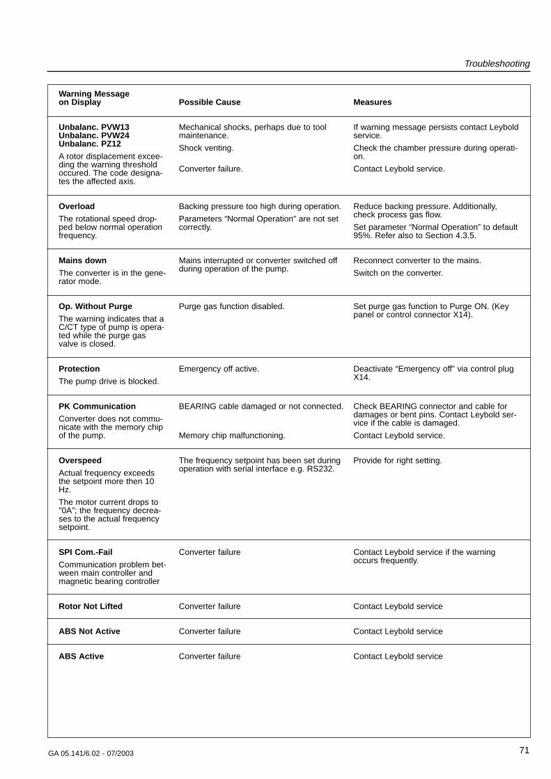
Troubleshooting
71GA 05.141/6.02 - 07/2003
Warning Message on Display
Unbalanc. PVW13Unbalanc. PVW24Unbalanc. PZ12
A rotor displacement excee-ding the warning thresholdoccured. The code designa-tes the affected axis.
Overload
The rotational speed drop-ped below normal operationfrequency.
Mains down
The converter is in the gene-rator mode.
Op. Without Purge
The warning indicates that aC/CT type of pump is opera-ted while the purge gasvalve is closed.
Protection
The pump drive is blocked.
PK Communication
Converter does not commu-nicate with the memory chipof the pump.
Overspeed
Actual frequency exceedsthe setpoint more then 10Hz.
The motor current drops to"0A”; the frequency decrea-ses to the actual frequencysetpoint.
SPI Com.-Fail
Communication problem bet-ween main controller andmagnetic bearing controller
Rotor Not Lifted
ABS Not Active
ABS Active
Measures
If warning message persists contact Leyboldservice.
Check the chamber pressure during operati-on.
Contact Leybold service.
Reduce backing pressure. Additionally,check process gas flow.
Set parameter “Normal Operation” to default95%. Refer also to Section 4.3.5.
Reconnect converter to the mains.
Switch on the converter.
Set purge gas function to Purge ON. (Keypanel or control connector X14).
Deactivate “Emergency off” via control plugX14.
Check BEARING connector and cable fordamages or bent pins. Contact Leybold ser-vice if the cable is damaged.
Contact Leybold service.
Provide for right setting.
Contact Leybold service if the warningoccurs frequently.
Contact Leybold service
Contact Leybold service
Contact Leybold service
Possible Cause
Mechanical shocks, perhaps due to toolmaintenance.
Shock venting.
Converter failure.
Backing pressure too high during operation.
Parameters “Normal Operation” are not setcorrectly.
Mains interrupted or converter switched offduring operation of the pump.
Purge gas function disabled.
Emergency off active.
BEARING cable damaged or not connected.
Memory chip malfunctioning.
The frequency setpoint has been set duringoperation with serial interface e.g. RS232.
Converter failure
Converter failure
Converter failure
Converter failure
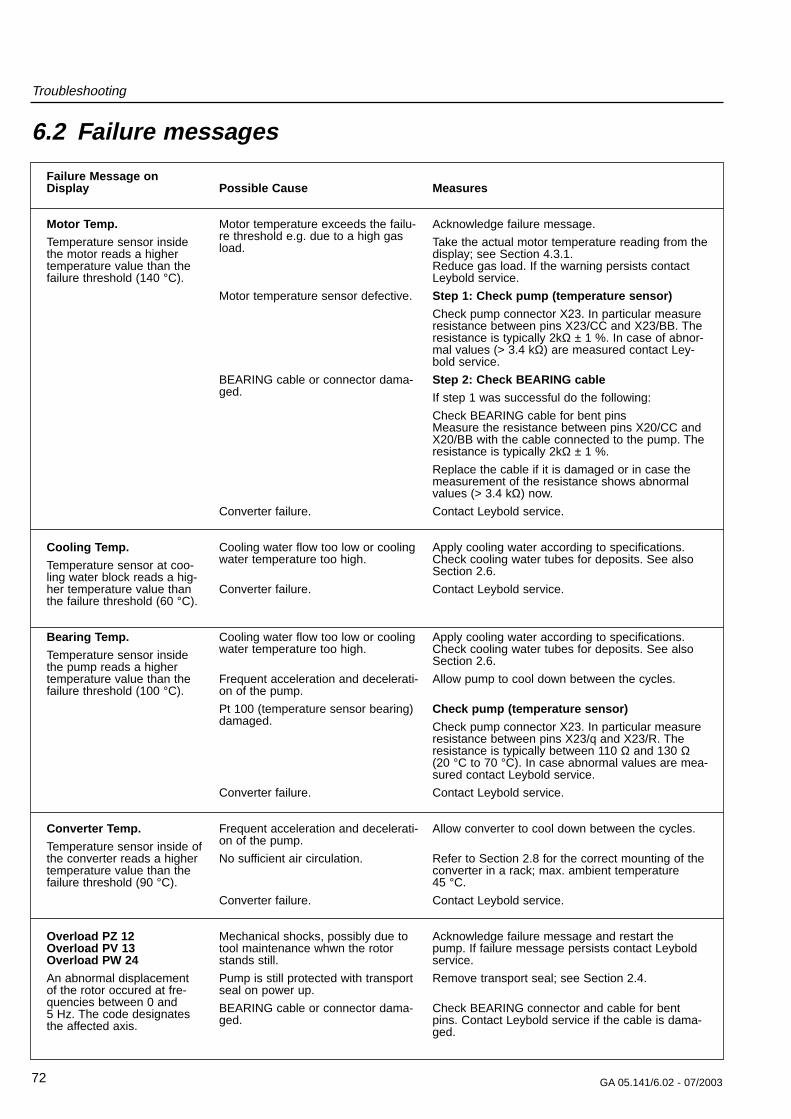
Troubleshooting
72 GA 05.141/6.02 - 07/2003
Failure Message on Display
Motor Temp.
Temperature sensor insidethe motor reads a highertemperature value than thefailure threshold (140 °C).
Cooling Temp.
Temperature sensor at coo-ling water block reads a hig-her temperature value thanthe failure threshold (60 °C).
Bearing Temp.
Temperature sensor insidethe pump reads a highertemperature value than thefailure threshold (100 °C).
Converter Temp.
Temperature sensor inside ofthe converter reads a highertemperature value than thefailure threshold (90 °C).
Overload PZ 12Overload PV 13Overload PW 24
An abnormal displacementof the rotor occured at fre-quencies between 0 and 5 Hz. The code designatesthe affected axis.
Measures
Acknowledge failure message.
Take the actual motor temperature reading from thedisplay; see Section 4.3.1.Reduce gas load. If the warning persists contactLeybold service.
Step 1: Check pump (temperature sensor)
Check pump connector X23. In particular measureresistance between pins X23/CC and X23/BB. Theresistance is typically 2kΩ ± 1 %. In case of abnor-mal values (> 3.4 kΩ) are measured contact Ley-bold service.
Step 2: Check BEARING cable
If step 1 was successful do the following:
Check BEARING cable for bent pinsMeasure the resistance between pins X20/CC andX20/BB with the cable connected to the pump. Theresistance is typically 2kΩ ± 1 %.
Replace the cable if it is damaged or in case themeasurement of the resistance shows abnormalvalues (> 3.4 kΩ) now.
Contact Leybold service.
Apply cooling water according to specifications.Check cooling water tubes for deposits. See alsoSection 2.6.
Contact Leybold service.
Apply cooling water according to specifications.Check cooling water tubes for deposits. See alsoSection 2.6.
Allow pump to cool down between the cycles.
Check pump (temperature sensor)
Check pump connector X23. In particular measureresistance between pins X23/q and X23/R. Theresistance is typically between 110 Ω and 130 Ω(20 °C to 70 °C). In case abnormal values are mea-sured contact Leybold service.
Contact Leybold service.
Allow converter to cool down between the cycles.
Refer to Section 2.8 for the correct mounting of theconverter in a rack; max. ambient temperature 45 °C.
Contact Leybold service.
Acknowledge failure message and restart thepump. If failure message persists contact Leyboldservice.
Remove transport seal; see Section 2.4.
Check BEARING connector and cable for bentpins. Contact Leybold service if the cable is dama-ged.
Possible Cause
Motor temperature exceeds the failu-re threshold e.g. due to a high gasload.
Motor temperature sensor defective.
BEARING cable or connector dama-ged.
Converter failure.
Cooling water flow too low or coolingwater temperature too high.
Converter failure.
Cooling water flow too low or coolingwater temperature too high.
Frequent acceleration and decelerati-on of the pump.
Pt 100 (temperature sensor bearing)damaged.
Converter failure.
Frequent acceleration and decelerati-on of the pump.
No sufficient air circulation.
Converter failure.
Mechanical shocks, possibly due totool maintenance whwn the rotorstands still.
Pump is still protected with transportseal on power up.
BEARING cable or connector dama-ged.
6.2 Failure messages
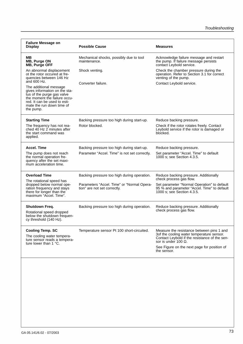
Troubleshooting
73GA 05.141/6.02 - 07/2003
Failure Message on Display
MBMB, Purge ONMB, Purge OFF
An abnormal displacementot the rotor occured at fre-quencies between 146 Hzand 600 Hz.
The additional messagegives information on the sta-tus of the purge gas valvethe moment the failure occu-red. It can be used to esti-mate the run down time ofthe pump.
Starting Time
The frequency has not rea-ched 40 Hz 2 minutes afterthe start command wasapplied.
Accel. Time
The pump does not reachthe normal operation fre-quency after the set maxi-mum acceleration time.
Overload Time
The rotational speed hasdropped below normal ope-ration frequency and staysthere for longer than themaximum “Accel. Time”.
Shutdown Freq.
Rotational speed droppedbelow the shutdown frequen-cy threshold (140 Hz).
Cooling Temp. SC
The cooling water tempera-ture sensor reads a tempera-ture lower than 1 °C.
Measures
Acknowledge failure message and restartthe pump. If failure message persistscontact Leybold service.
Check the chamber pressure during theoperation. Refer to Section 3.1 for correctventing of the pump.
Contact Leybold service.
Reduce backing pressure.
Check if the rotor rotates freely. ContactLeybold service if the rotor is damaged orblocked.
Reduce backing pressure.
Set parameter “Accel. Time” to default 1000 s; see Section 4.3.5.
Reduce backing pressure. Additionallycheck process gas flow.
Set parameter “Normal Operation” to default95 % and parameter “Accel. Time” to default1000 s; see Section 4.3.5.
Reduce backing pressure. Additionallycheck process gas flow.
Measure the resistance between pins 1 and3of the cooling water temperature sensor.Contact Leybold if the resistance of the sen-sor is under 100 Ω.
See Figure on the next page for position ofthe sensor.
Possible Cause
Mechanical shocks, possibly due to toolmaintenance.
Shock venting.
Converter failure.
Backing pressure too high during start-up.
Rotor blocked.
Backing pressure too high during start-up.
Parameter “Accel. Time” is not set correctly.
Backing pressure too high during operation.
Parameters “Accel. Time” or “Normal Opera-tion” are not set correctly.
Backing pressure too high during operation.
Temperature sensor Pt 100 short-circuited.
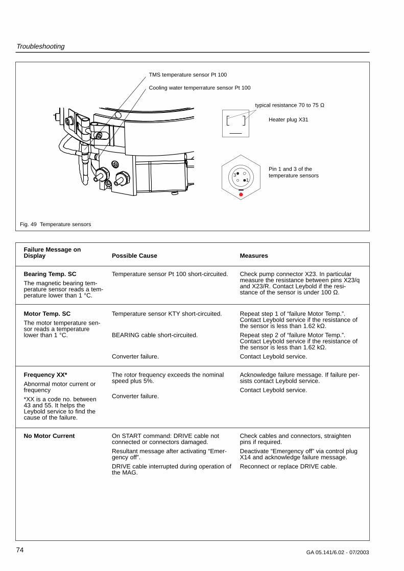
Troubleshooting
74 GA 05.141/6.02 - 07/2003
Fig. 49 Temperature sensors
31
Failure Message on Display
Bearing Temp. SC
The magnetic bearing tem-perature sensor reads a tem-perature lower than 1 °C.
Motor Temp. SC
The motor temperature sen-sor reads a temperaturelower than 1 °C.
Frequency XX*
Abnormal motor current orfrequency
*XX is a code no. between43 and 55. It helps the Leybold service to find thecause of the failure.
No Motor Current
Measures
Check pump connector X23. In particularmeasure the resistance between pins X23/qand X23/R. Contact Leybold if the resi-stance of the sensor is under 100 Ω.
Repeat step 1 of “failure Motor Temp.”.Contact Leybold service if the resistance ofthe sensor is less than 1.62 kΩ.
Repeat step 2 of “failure Motor Temp.”.Contact Leybold service if the resistance ofthe sensor is less than 1.62 kΩ.
Contact Leybold service.
Acknowledge failure message. If failure per-sists contact Leybold service.
Contact Leybold service.
Check cables and connectors, straightenpins if required.
Deactivate “Emergency off” via control plugX14 and acknowledge failure message.
Reconnect or replace DRIVE cable.
Possible Cause
Temperature sensor Pt 100 short-circuited.
Temperature sensor KTY short-circuited.
BEARING cable short-circuited.
Converter failure.
The rotor frequency exceeds the nominalspeed plus 5%.
Converter failure.
On START command: DRIVE cable notconnected or connectors damaged.
Resultant message after activating “Emer-gency off”.
DRIVE cable interrupted during operation ofthe MAG.
TMS temperature sensor Pt 100
Cooling water temperrature sensor Pt 100
Pin 1 and 3 of the temperature sensors
Heater plug X31
typical resistance 70 to 75 Ω
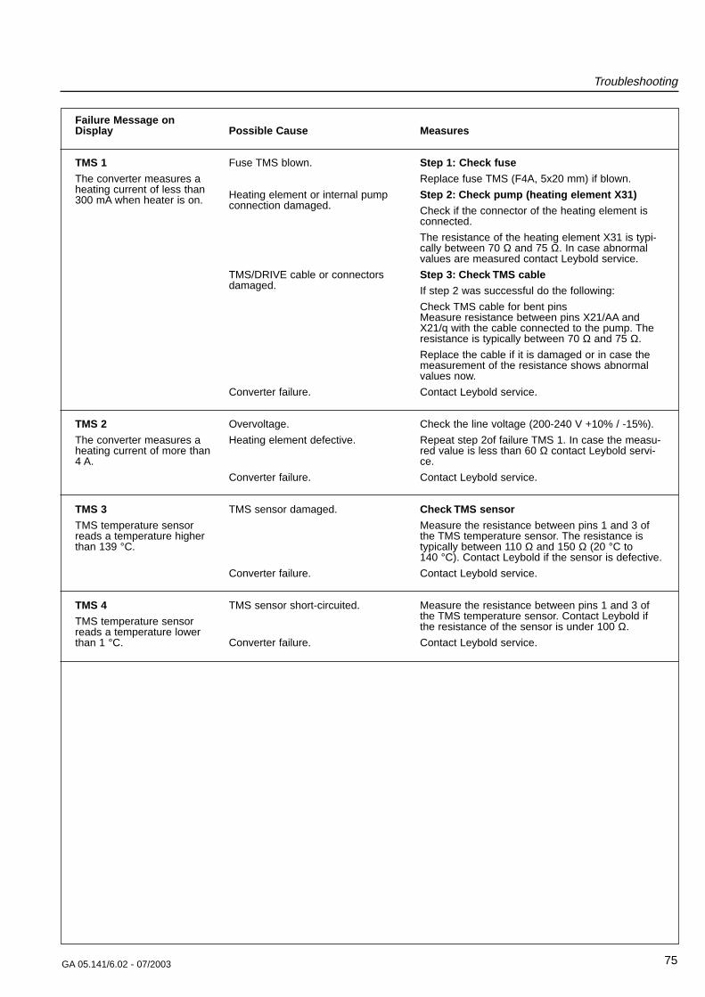
Troubleshooting
75GA 05.141/6.02 - 07/2003
Failure Message on Display
TMS 1
The converter measures aheating current of less than300 mA when heater is on.
TMS 2
The converter measures aheating current of more than4 A.
TMS 3
TMS temperature sensorreads a temperature higherthan 139 °C.
TMS 4
TMS temperature sensorreads a temperature lowerthan 1 °C.
Measures
Step 1: Check fuse
Replace fuse TMS (F4A, 5x20 mm) if blown.
Step 2: Check pump (heating element X31)
Check if the connector of the heating element isconnected.
The resistance of the heating element X31 is typi-cally between 70 Ω and 75 Ω. In case abnormalvalues are measured contact Leybold service.
Step 3: Check TMS cable
If step 2 was successful do the following:
Check TMS cable for bent pinsMeasure resistance between pins X21/AA andX21/q with the cable connected to the pump. Theresistance is typically between 70 Ω and 75 Ω.
Replace the cable if it is damaged or in case themeasurement of the resistance shows abnormalvalues now.
Contact Leybold service.
Check the line voltage (200-240 V +10% / -15%).
Repeat step 2of failure TMS 1. In case the measu-red value is less than 60 Ω contact Leybold servi-ce.
Contact Leybold service.
Check TMS sensor
Measure the resistance between pins 1 and 3 ofthe TMS temperature sensor. The resistance istypically between 110 Ω and 150 Ω (20 °C to 140 °C). Contact Leybold if the sensor is defective.
Contact Leybold service.
Measure the resistance between pins 1 and 3 ofthe TMS temperature sensor. Contact Leybold ifthe resistance of the sensor is under 100 Ω.
Contact Leybold service.
Possible Cause
Fuse TMS blown.
Heating element or internal pumpconnection damaged.
TMS/DRIVE cable or connectorsdamaged.
Converter failure.
Overvoltage.
Heating element defective.
Converter failure.
TMS sensor damaged.
Converter failure.
TMS sensor short-circuited.
Converter failure.
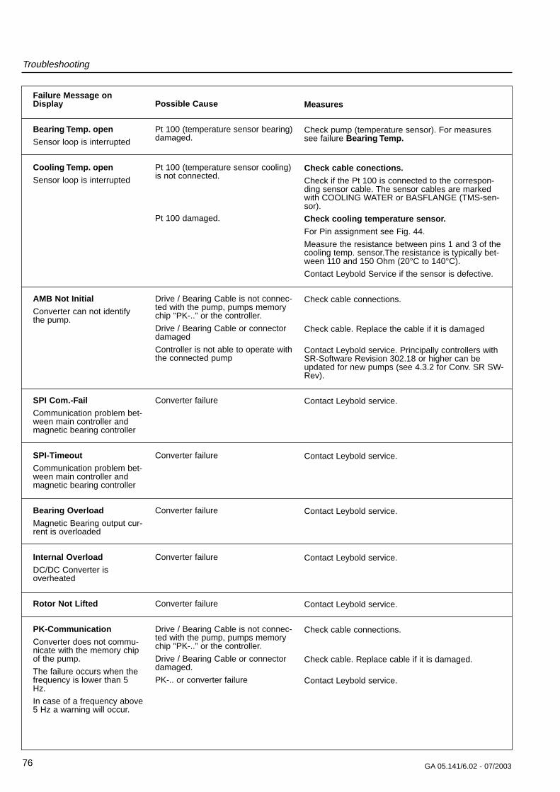
Measures
Check pump (temperature sensor). For measuressee failure Bearing Temp.
Check cable conections.
Check if the Pt 100 is connected to the correspon-ding sensor cable. The sensor cables are markedwith COOLING WATER or BASFLANGE (TMS-sen-sor).
Check cooling temperature sensor.
For Pin assignment see Fig. 44.
Measure the resistance between pins 1 and 3 of thecooling temp. sensor.The resistance is typically bet-ween 110 and 150 Ohm (20°C to 140°C).
Contact Leybold Service if the sensor is defective.
Check cable connections.
Check cable. Replace the cable if it is damaged
Contact Leybold service. Principally controllers withSR-Software Revision 302.18 or higher can beupdated for new pumps (see 4.3.2 for Conv. SR SW-Rev).
Contact Leybold service.
Contact Leybold service.
Contact Leybold service.
Contact Leybold service.
Contact Leybold service.
Check cable connections.
Check cable. Replace cable if it is damaged.
Contact Leybold service.
Troubleshooting
76 GA 05.141/6.02 - 07/2003
Failure Message on Display
Bearing Temp. open
Sensor loop is interrupted
Cooling Temp. open
Sensor loop is interrupted
AMB Not Initial
Converter can not identifythe pump.
SPI Com.-Fail
Communication problem bet-ween main controller andmagnetic bearing controller
SPI-Timeout
Communication problem bet-ween main controller andmagnetic bearing controller
Bearing Overload
Magnetic Bearing output cur-rent is overloaded
Internal Overload
DC/DC Converter isoverheated
Rotor Not Lifted
PK-Communication
Converter does not commu-nicate with the memory chipof the pump.
The failure occurs when thefrequency is lower than 5Hz.
In case of a frequency above5 Hz a warning will occur.
Possible Cause
Pt 100 (temperature sensor bearing)damaged.
Pt 100 (temperature sensor cooling)is not connected.
Pt 100 damaged.
Drive / Bearing Cable is not connec-ted with the pump, pumps memorychip "PK-..” or the controller.
Drive / Bearing Cable or connectordamaged
Controller is not able to operate withthe connected pump
Converter failure
Converter failure
Converter failure
Converter failure
Converter failure
Drive / Bearing Cable is not connec-ted with the pump, pumps memorychip "PK-..” or the controller.
Drive / Bearing Cable or connectordamaged.
PK-.. or converter failure
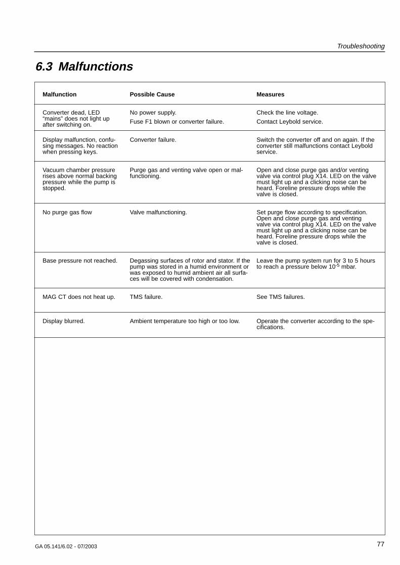
Troubleshooting
77GA 05.141/6.02 - 07/2003
Malfunction
Converter dead, LED“mains” does not light upafter switching on.
Display malfunction, confu-sing messages. No reactionwhen pressing keys.
Vacuum chamber pressurerises above normal backingpressure while the pump isstopped.
No purge gas flow
Base pressure not reached.
MAG CT does not heat up.
Display blurred.
Measures
Check the line voltage.
Contact Leybold service.
Switch the converter off and on again. If theconverter still malfunctions contact Leyboldservice.
Open and close purge gas and/or ventingvalve via control plug X14. LED on the valvemust light up and a clicking noise can beheard. Foreline pressure drops while thevalve is closed.
Set purge flow according to specification.Open and close purge gas and ventingvalve via control plug X14. LED on the valvemust light up and a clicking noise can beheard. Foreline pressure drops while thevalve is closed.
Leave the pump system run for 3 to 5 hoursto reach a pressure below 10-5 mbar.
See TMS failures.
Operate the converter according to the spe-cifications.
Possible Cause
No power supply.
Fuse F1 blown or converter failure.
Converter failure.
Purge gas and venting valve open or mal-functioning.
Valve malfunctioning.
Degassing surfaces of rotor and stator. If thepump was stored in a humid environment orwas exposed to humid ambient air all surfa-ces will be covered with condensation.
TMS failure.
Ambient temperature too high or too low.
6.3 Malfunctions
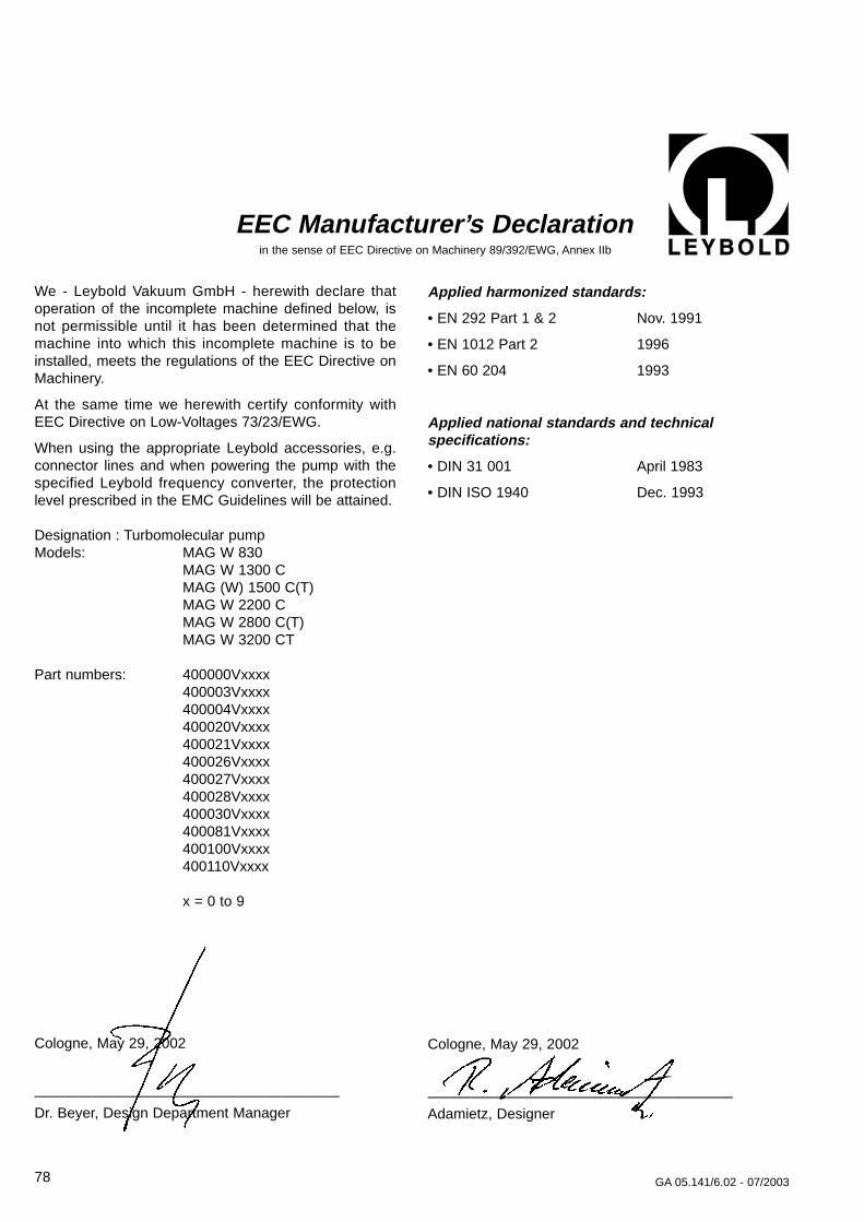
We - Leybold Vakuum GmbH - herewith declare thatoperation of the incomplete machine defined below, isnot permissible until it has been determined that themachine into which this incomplete machine is to beinstalled, meets the regulations of the EEC Directive onMachinery.
At the same time we herewith certify conformity withEEC Directive on Low-Voltages 73/23/EWG.
When using the appropriate Leybold accessories, e.g.connector lines and when powering the pump with thespecified Leybold frequency converter, the protectionlevel prescribed in the EMC Guidelines will be attained.
Designation : Turbomolecular pumpModels: MAG W 830
MAG W 1300 CMAG (W) 1500 C(T)MAG W 2200 CMAG W 2800 C(T)MAG W 3200 CT
Part numbers: 400000Vxxxx400003Vxxxx400004Vxxxx400020Vxxxx400021Vxxxx400026Vxxxx400027Vxxxx400028Vxxxx400030Vxxxx400081Vxxxx400100Vxxxx400110Vxxxx
x = 0 to 9
78 GA 05.141/6.02 - 07/2003
Cologne, May 29, 2002
—————————————————————Dr. Beyer, Design Department Manager
EEC Manufacturer’s Declarationin the sense of EEC Directive on Machinery 89/392/EWG, Annex IIb
Applied harmonized standards:
• EN 292 Part 1 & 2 Nov. 1991
• EN 1012 Part 2 1996
• EN 60 204 1993
Applied national standards and technical specifications:
• DIN 31 001 April 1983
• DIN ISO 1940 Dec. 1993
Cologne, May 29, 2002
—————————————————————Adamietz, Designer
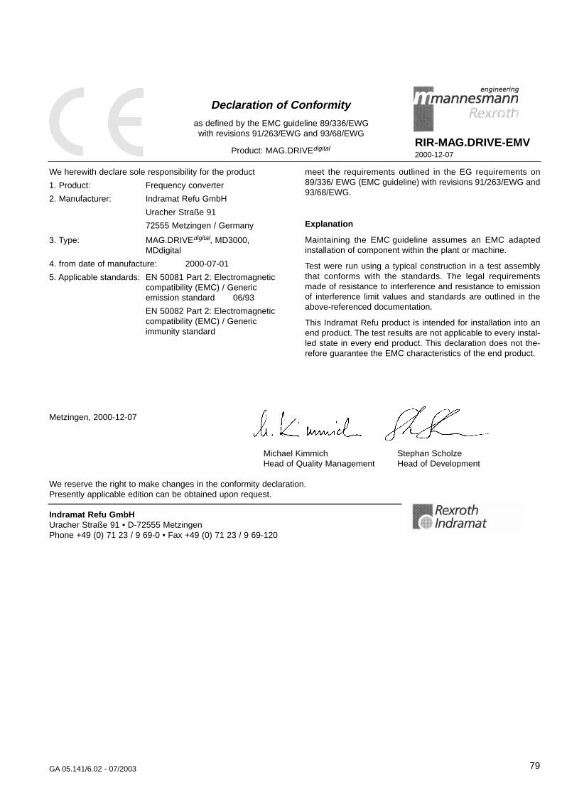
79GA 05.141/6.02 - 07/2003
Declaration of Conformity
as defined by the EMC guideline 89/336/EWG with revisions 91/263/EWG and 93/68/EWG
Product: MAG.DRIVEdigitalRIR-MAG.DRIVE-EMV2000-12-07
meet the requirements outlined in the EG requirements on89/336/ EWG (EMC guideline) with revisions 91/263/EWG and93/68/EWG.
Explanation
Maintaining the EMC guideline assumes an EMC adaptedinstallation of component within the plant or machine.
Test were run using a typical construction in a test assemblythat conforms with the standards. The legal requirementsmade of resistance to interference and resistance to emissionof interference limit values and standards are outlined in theabove-referenced documentation.
This Indramat Refu product is intended for installation into anend product. The test results are not applicable to every instal-led state in every end product. This declaration does not the-refore guarantee the EMC characteristics of the end product.
We herewith declare sole responsibility for the product
1. Product: Frequency converter
2. Manufacturer: Indramat Refu GmbH
Uracher Straße 91
72555 Metzingen / Germany
3. Type: MAG.DRIVEdigital, MD3000, MDdigital
4. from date of manufacture: 2000-07-01
5. Applicable standards: EN 50081 Part 2: Electromagnetic compatibility (EMC) / Generic emission standard 06/93
EN 50082 Part 2: Electromagnetic compatibility (EMC) / Generic immunity standard
Metzingen, 2000-12-07
Michael Kimmich Stephan ScholzeHead of Quality Management Head of Development
We reserve the right to make changes in the conformity declaration. Presently applicable edition can be obtained upon request.
Indramat Refu GmbHUracher Straße 91 • D-72555 MetzingenPhone +49 (0) 71 23 / 9 69-0 • Fax +49 (0) 71 23 / 9 69-120
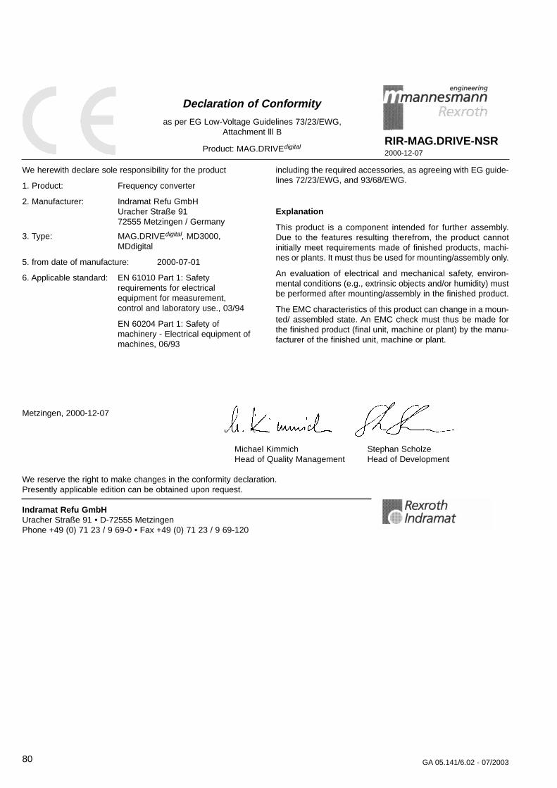
80 GA 05.141/6.02 - 07/2003
Declaration of Conformity
as per EG Low-Voltage Guidelines 73/23/EWG,Attachment lll B
Product: MAG.DRIVEdigitalRIR-MAG.DRIVE-NSR2000-12-07
including the required accessories, as agreeing with EG guide-lines 72/23/EWG, and 93/68/EWG.
Explanation
This product is a component intended for further assembly.Due to the features resulting therefrom, the product cannotinitially meet requirements made of finished products, machi-nes or plants. It must thus be used for mounting/assembly only.
An evaluation of electrical and mechanical safety, environ-mental conditions (e.g., extrinsic objects and/or humidity) mustbe performed after mounting/assembly in the finished product.
The EMC characteristics of this product can change in a moun-ted/ assembled state. An EMC check must thus be made forthe finished product (final unit, machine or plant) by the manu-facturer of the finished unit, machine or plant.
We herewith declare sole responsibility for the product
1. Product: Frequency converter
2. Manufacturer: Indramat Refu GmbHUracher Straße 9172555 Metzingen / Germany
3. Type: MAG.DRIVEdigital, MD3000, MDdigital
5. from date of manufacture: 2000-07-01
6. Applicable standard: EN 61010 Part 1: Safety requirements for electrical equipment for measurement, control and laboratory use., 03/94
EN 60204 Part 1: Safety of machinery - Electrical equipment of machines, 06/93
Metzingen, 2000-12-07
Michael Kimmich Stephan ScholzeHead of Quality Management Head of Development
We reserve the right to make changes in the conformity declaration. Presently applicable edition can be obtained upon request.
Indramat Refu GmbHUracher Straße 91 • D-72555 MetzingenPhone +49 (0) 71 23 / 9 69-0 • Fax +49 (0) 71 23 / 9 69-120
81GA 05.141/6.02 - 07/2003
The system MAG 1500
• turbomolecular pump
• connecting cables
• frequency converter
has been tested by the TUV Rheinland of North Americaaccording to the requirements of
• NRTL(used standard UL 3101-1/10.93)
• Semi S2-0200used standards:SEMI S2-0200UL 3111 / UL 3101EU Low Voltage DirectiveEU Machinery DirectiveEU EMC Directive
The components are in compliance to the tested stan-dards.
NRTL Report No. USA-JK/lt G 9972057.02
Certificate No. US 9971855 02
Evaluation Report file #E2110736.01
The MAG 830, MAG 1300, MAG 2200, MAG 2800 andMAG 3200 systems have been designed following thesame standards but have not yet been tested.
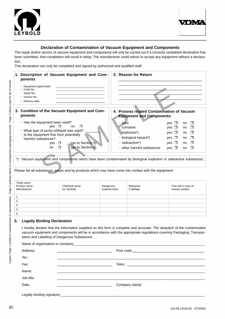
82 GA 05.141/6.02 - 07/2003
S AM P
L E
Declaration of Contamination of Vacuum Equipment and ComponentsThe repair and/or service of vacuum equipment and components will only be carried out if a correctly completed declaration hasbeen submitted. Non-completion will result in delay. The manufacturer could refuse to accept any equipment without a declara-tion.This declaration can only be completed and signed by authorized and qualified staff.
1. Description of Vacuum Equipment and Com-ponents
- Equipment type/model: _________________________________- Code No.: _________________________________- Serial No.: _________________________________- Invoice No.: _________________________________
- Delivery date: __________________________
2. Reason for Return________________________________________________________________________________________________________________________________________________________________________________
____________________________________________
3. Condition of the Vacuum Equipment and Com-ponents
- Has the equipment been used?yes no
- What type of pump oil/liquid was used? _________- Is the equipment free from potentially
harmful substances?yes (go to Section 5)no (go to Section 4)
4. Process related Contamination of Vacuum Equipment and Components:
- toxic yes no - corrosive yes no
- explosive*) yes no
- biological hazard*) yes no
- radioactive*) yes no
- other harmful substances yes no
*) Vacuum equipment and components which have been contaminated by biological explosive or radioactive substances,
Please list all substances, gases and by-products which may have come into contact with the equipment:
Trade nameProduct name Chemical name Dangerous Measures First aid in case ofManufacturer (or Symbol) material class if spillage human contact
1.
2.
3.
4.
5.
Cop
ies:
Pag
e 1
(whi
te)
to m
anuf
actu
rer
or r
epre
sent
ativ
e -
Pag
e 2
(yel
low
) at
tach
to
cons
ignm
ent
pack
agin
g se
cure
ty -
Pag
e 3
(blu
e) c
opy
for
file
of s
ende
r
5. Legally Binding Declaration
I hereby declare that the information supplied on this form is complete and accurate. The despatch of the contaminatedvacuum equipment and components will be in accordance with the appropriate regulations covering Packaging, Transpor-tation and Labelling of Dangerous Substances.
Name of organisation or company:_____________________________________________________________________
Address: _____________________________ Post code:______________________________________
Tel.: ______________________________________________________________________________
Fax: _____________________________ Telex: _________________________________________
Name: ______________________________________________________________________________
Job title: ______________________________________________________________________________
Date: _____________________________ Company stamp:
Legally binding signature:____________________________________________________________________________
83GA 05.141/6.02 - 07/2003
Form TMP-1 … Turbopump Field Failure ReportField Service IR No.: RMA No. (if returning to factory):
Service Center:
Customer:
Turbopump Model: Turbopump Pump Part Number:
Turbopump Serial Number:
Complaint:
Process:
OEM Equipment Name and Model:
Process Gas:
Was the turbopump replaced? Yes; No.
If yes, replacement pump P/N: replacement pump S/N:
Date Installed: Date Removed:
Date Received:
Date Examined: Examined by:
Received Condition:
Findings:
Cause of Failure:
Recommendations:
Remarks/Questions:
LEYBOLD VACUUM
Fax to: Service LVFax#: (0049) 221 347 1945
LEYBOLD VACUUM
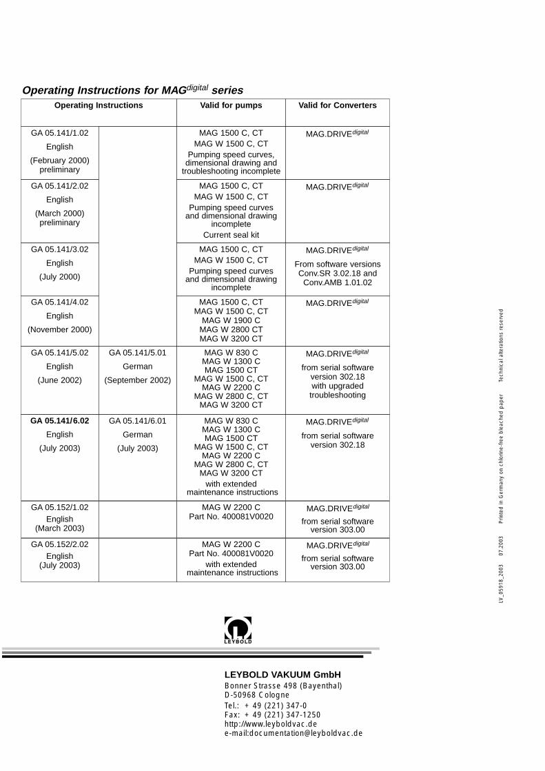
LEYBOLD VAKUUM GmbHBonner Strasse 498 (Bayenthal)D-50968 CologneTel.: + 49 (221) 347-0Fax: + 49 (221) 347-1250http://www.leyboldvac.dee-mail:[email protected]
LV_0
5918
_200
3
07
.200
3P
rinte
d in
Ger
man
y on
chl
orin
e-fre
e b
leac
hed
pap
erTe
chni
cal a
ltera
tions
res
erve
d
Operating Instructions for MAGdigital seriesValid for pumps
MAG 1500 C, CTMAG W 1500 C, CT
Pumping speed curves,dimensional drawing and
troubleshooting incomplete
MAG 1500 C, CTMAG W 1500 C, CT
Pumping speed curves and dimensional drawing
incompleteCurrent seal kit
GA 05.141/1.02
English
(February 2000)preliminary
Valid for Converters
MAG.DRIVEdigital
MAG.DRIVEdigitalGA 05.141/2.02
English
(March 2000)preliminary
MAG 1500 C, CTMAG W 1500 C, CT
Pumping speed curves and dimensional drawing
incomplete
MAG.DRIVEdigital
From software versionsConv.SR 3.02.18 and
Conv.AMB 1.01.02
GA 05.141/3.02
English
(July 2000)
MAG 1500 C, CTMAG W 1500 C, CT
MAG W 1900 CMAG W 2800 CTMAG W 3200 CT
MAG.DRIVEdigitalGA 05.141/4.02
English
(November 2000)
Operating Instructions
MAG W 830 CMAG W 1300 CMAG 1500 CT
MAG W 1500 C, CTMAG W 2200 C
MAG W 2800 C, CTMAG W 3200 CT
MAG.DRIVEdigital
from serial software version 302.18with upgraded troubleshooting
GA 05.141/5.02
English
(June 2002)
GA 05.141/5.01
German
(September 2002)
MAG W 2200 CPart No. 400081V0020
MAG.DRIVEdigital
from serial software version 303.00
GA 05.152/1.02English
(March 2003)
MAG.DRIVEdigital
from serial software version 302.18
GA 05.141/6.02
English
(July 2003)
GA 05.141/6.01
German
(July 2003)
MAG W 830 CMAG W 1300 CMAG 1500 CT
MAG W 1500 C, CTMAG W 2200 C
MAG W 2800 C, CTMAG W 3200 CT
with extendedmaintenance instructions
MAG W 2200 CPart No. 400081V0020
with extendedmaintenance instructions
MAG.DRIVEdigital
from serial software version 303.00
GA 05.152/2.02English
(July 2003)