Embed Size (px)
Citation preview

36 VOLUME 24, No. 4, 2020 * Corresponding author: Robert Čep, E-mail address: [email protected]
Acta Mechanica Slovaca 24 (4): 36 - 42, December 2020https://doi.org/10.21496/ams.2021.002
Acta Mechanica SlovacaISSN 1335-2393
www.actamechanica.sk
Machine Tool Accuracy DMG MORI DMU 50 measuring by system Ballbar QC20-W
Radim Liška1, Dagmar Šoková1, Robert Čep1*, Lenka Čepová1 and Jiří Kratochvíl1
1 VŠB-Technical university of Ostrava, Faculty of Mechanical Engineering, 17. Listopadu 2172/15, 708 00 Ostrava, Czech Republic
Abstract: This article deals with the measurement and evaluation of the circularity of the machine DMG MORI - DMU 50 using the measuring system Ballbar QC20-W, which can measure the circularity of the machine using circular interpolation. Furthermore, the system can evaluate machine errors or measurement errors. This can prevent a number of problems, such as financial losses, compliance with the required accuracy and adherence to order deadlines. All three planes of the machine tool were measured - XY, YZ and ZX. In each plane, accuracy (roundness deviations) was measured at three values of feed rate 1000, 1500 and 2000 m.min-1. Each measurement was evaluated and in the end the dependence in individual planes on the feed rate is given.
Keywords: machine tool; accuracy; roundness deviation; measuring; Ballbar QC20-W
1. Introduction
We live in a time when the emphasis is primarily on price, speed, accuracy and quality. Thanks to this, CNC machines have their inseparable place in mechanical engineering. Their use can be seen in the automotive, aerospace, rubber, and other industries, which have a great impact on our daily lives [1].
However, they also have a place in the dental industry, where they are used to produce, for example, tooth crowns, but also entire dentures. In the medical industry, it is used to produce surgical implants, such as artificial joints. However, for their operation to be reliable, regular maintenance and verification of their accuracy is required. Especially with machines that work continuously and develop inaccuracies and wear much faster. Neglecting to maintain the machine can lead to a situation where the machine will have to be shut down and wait a long time for repair, which will cause financial losses in the company. During the regular inspection, it is possible to find out how great the inaccuracy of the machine is and thanks to that decide what work can be done on the given machine, or to schedule maintenance, when it will be convenient. This can be achieved with various measuring systems [1].
One of the most important features of CNC machine tools is their accuracy. The accuracy of production machines is evaluated as working and geometric accuracy. [2, 7]. Accuracy is given by the sum of mechanical and control system errors, which are minimal today. Today, standard CNC machines operate with an accuracy of 0.001 mm [2]. We evaluate the working accuracy on a standard product, which is manufactured under defined conditions. [3, 4]. We evaluate the geometric accuracy without loading the machine. Here, the deviations of the paths of the individual movements of the machine parts are evaluated simultaneously with the deviations in the shape of important functional surfaces (eg the clamping surface of the table). [3] Every machine, whether new, overhauled or rebuilt, must be inspected for geometric accuracy. The inspection is performed during the output inspection as well as during operation
Acta Mechanica SlovacaJournal published by Faculty of Mechanical Engineering - Technical University of Košice
37
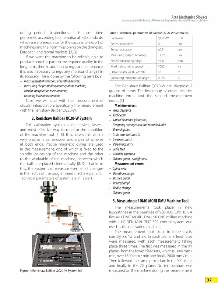
Figure 1: Renishaw Ballbar QC20-W System [6].
during periodic inspections. It is most often performed according to international ISO standards, which are a prerequisite for the successful export of machines and their commissioning on the domestic, European and global markets. [3, 8]
If we want the machine to be reliable, able to produce portable parts in the required quality, in the long term, then in addition to regular maintenance, it is also necessary to regularly monitor changes in its accuracy. This is done by the following tests [5, 9]: – measurement of vibrations of rotating devices;– measuring the positioning accuracy of the machine;– circular interpolation measurement;– clamping force measurement;
Next, we will deal with the measurement of circular interpolation, specifically the measurement with the Renishaw Ballbar QC20-W.
2. Renishaw Ballbar QC20-W SystemThis calibration system is the easiest, fastest,
and most effective way to monitor the condition of the machine tool [7, 8]. It achieves this with a very precise linear encoder and a pair of spheres at both ends. Precise magnetic dishes are used in the measurement, one of which is fixed to the spindle (or casing) of the machine and the other to the worktable of the machine, between which the balls are placed cinematically [8, 9]. Thanks to this, the system can measure even small changes in the radius of the programmed machine path. [6]. Technical parameters of system are in Table 1.
Table 1: Technical parameters of Ballbar QC20-W system [6].
Parameter QC20-W Unit
Senzor resolution 0,1 μm
Senzor accuracy ±0,5 μm
Measuring systém accuracy ±1,25 μm
Senzot measuring range ±1,0 mm
Maximal scanning speed 1000 Hz
Data transfer via Bluetooth 10 m
Operating temperature range 0 - 40 °C
The Renishaw Ballbar QC20-W can diagnose 2 groups of errors. The first group of errors includes machine errors and the second measurement errors. [5]
Machine errors:– Axial clearance – Cyclic error – Lateral clearance (deviation) – Swapping management and controlled roles – Reversing tips – Scale error (mismatch) – Servo mismatch – Perpendicularity – Jerky feed – Machine vibration – Trilobal graph - straightness
Measurement errors: – Spiral error – Deviation change – Dashed graph – Rotated graph – Radius change – Trilobal graph
3. Measuring of DMG MORI DMU Machine ToolThe measurements took place in new
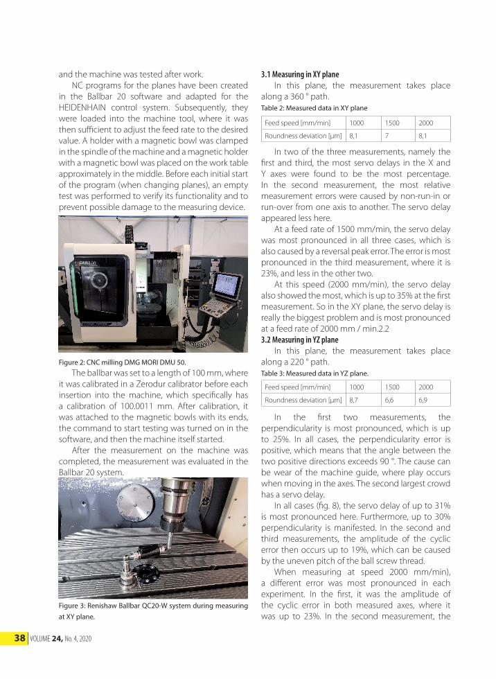
laboratories in the premises of VŠB-TUO CPIT TL1. A five-axis DMG MORI - DMU 50 CNC milling machine with a HEIDENHAIN iTNC 530 control system was used as the measuring machine.
The measurement took place in three levels, namely XY, YZ and ZX. In each plane, 3 feed rates were measured, with each measurement taking place three times. The first was measured in the XY planes, from the lowest feed rate, which is 1000 mm / min, over 1500 mm / min and finally 2000 mm / min. Then followed the same procedure in the YZ plane, and finally in the ZX plane. No temperature was measured on the machine during the measurement
38 VOLUME 24, No. 4, 2020
and the machine was tested after work. NC programs for the planes have been created
in the Ballbar 20 software and adapted for the HEIDENHAIN control system. Subsequently, they were loaded into the machine tool, where it was then sufficient to adjust the feed rate to the desired value. A holder with a magnetic bowl was clamped in the spindle of the machine and a magnetic holder with a magnetic bowl was placed on the work table approximately in the middle. Before each initial start of the program (when changing planes), an empty test was performed to verify its functionality and to prevent possible damage to the measuring device.
3.1 Measuring in XY planeIn this plane, the measurement takes place
along a 360 ° path.Table 2: Measured data in XY plane
Figure 2: CNC milling DMG MORI DMU 50.The ballbar was set to a length of 100 mm, where
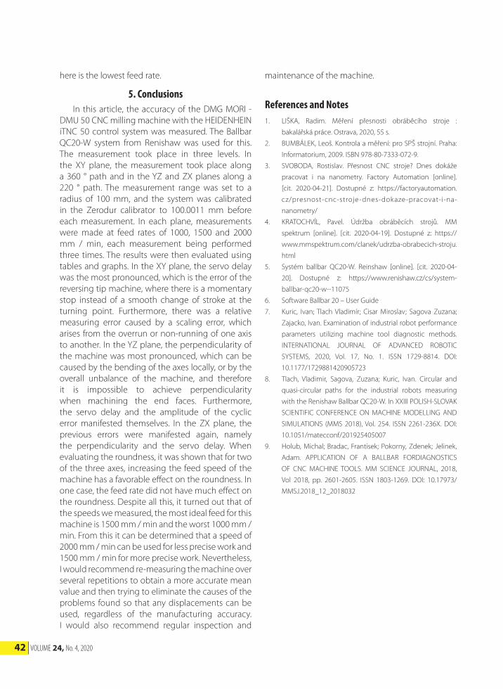
it was calibrated in a Zerodur calibrator before each insertion into the machine, which specifically has a calibration of 100.0011 mm. After calibration, it was attached to the magnetic bowls with its ends, the command to start testing was turned on in the software, and then the machine itself started.
After the measurement on the machine was completed, the measurement was evaluated in the Ballbar 20 system.
Figure 3: Renishaw Ballbar QC20-W system during measuring at XY plane.
Feed speed [mm/min] 1000 1500 2000
Roundness deviation [μm] 8,1 7 8,1
In two of the three measurements, namely the first and third, the most servo delays in the X and Y axes were found to be the most percentage. In the second measurement, the most relative measurement errors were caused by non-run-in or run-over from one axis to another. The servo delay appeared less here.
At a feed rate of 1500 mm/min, the servo delay was most pronounced in all three cases, which is also caused by a reversal peak error. The error is most pronounced in the third measurement, where it is 23%, and less in the other two.
At this speed (2000 mm/min), the servo delay also showed the most, which is up to 35% at the first measurement. So in the XY plane, the servo delay is really the biggest problem and is most pronounced at a feed rate of 2000 mm / min.2.2 3.2 Measuring in YZ plane
In this plane, the measurement takes place along a 220 ° path.Table 3: Measured data in YZ plane.
Feed speed [mm/min] 1000 1500 2000
Roundness deviation [μm] 8,7 6,6 6,9
In the first two measurements, the perpendicularity is most pronounced, which is up to 25%. In all cases, the perpendicularity error is positive, which means that the angle between the two positive directions exceeds 90 °. The cause can be wear of the machine guide, where play occurs when moving in the axes. The second largest crowd has a servo delay.
In all cases (fig. 8), the servo delay of up to 31% is most pronounced here. Furthermore, up to 30% perpendicularity is manifested. In the second and third measurements, the amplitude of the cyclic error then occurs up to 19%, which can be caused by the uneven pitch of the ball screw thread.
When measuring at speed 2000 mm/min), a different error was most pronounced in each experiment. In the first, it was the amplitude of the cyclic error in both measured axes, where it was up to 23%. In the second measurement, the

Acta Mechanica SlovacaJournal published by Faculty of Mechanical Engineering - Technical University of Košice
39
Figure 4: Measured graphs in XY plane at feed speed 1000 mm/min (3 independent measuring).
Figure 5: Measured graphs in XY plane at feed speed 1500 mm/min (3 independent measuring).
Figure 6: Measured graphs in XY plane at feed speed 2000 mm/min (3 independent measuring).
Figure 7: Measured graphs in YZ plane at feed speed 1000 mm/min (3 independent measuring).

40 VOLUME 24, No. 4, 2020
delay of the servos with transverse play was most pronounced, where they are the main cause of play in the machine guide. In the third measurement, the perpendicularity was 26%.3.3 Measuring in ZX plane
In this plane, the measurement takes place along a 220 ° path.Table 4: Measured data in ZX plane
Figure 8: Measured graphs in YZ plane at feed speed 1500 mm/min (3 independent measuring).
Figure 9: Measured graphs in YZ plane at feed speed 2000 mm/min (3 independent measuring).
Feed speed [mm/min] 1000 1500 2000
Roundness deviation [μm] 5,9 4,7 4,6
Perpendicularity was the most pronounced here, which was up to 34%. There was also a servo delay of 16% and a lateral play of 14%.
As with a feed rate of 1000 mm / min, the perpendicularity, which was up to 30%, and then the servo delay were the most pronounced.
The amplitude of the cyclic error reached 30% in the second measurement, otherwise the perpendicularity was again most pronounced up to 35%. Although the measurements were performed immediately after each other under the same conditions and the same procedures, the measurement graphs at a speed of 2000 mm / min in the ZX plane differ considerably.
4. Evaluation of roundness deviationCircularity is the difference between the largest
and smallest radii, which is recorded by the ballbar as the machine moves along the path of the data acquisition arc. The lower the value, the better the accuracy of the machine. [5]
The following table lists all the mean values of roundness, measured in individual planes at certain speeds.Table 5: Table of resulting roundnesses
Feed speed [mm/min] 1000 1500 2000
Roundness deviation [μm] XY 8,1 7,0 8,1
Roundness deviation [μm] YZ 8,7 6,6 6,9
Roundness deviation [μm] ZX 5,9 4,7 4,6
As shown in the following graph (Fig. 13), in the XY plane, with the addition of the feed rate, the roundness first decreased and then increased again to the original value. At the YZ plane, this condition also occurred, but not with such a renewed increase. In the ZX plane, the circularity manifested itself only by a decrease. It follows that, as shown in the following graph, the circularity is constant in the XY plane, so that the increase in speed has no effect on it. In the other two planes YZ and ZX, the

Acta Mechanica SlovacaJournal published by Faculty of Mechanical Engineering - Technical University of Košice
41
Figure 10: Measured graphs in ZX plane at feed speed 1000 mm/min (3 independent measuring).
Figure 11: Measured graphs in ZX plane at feed speed 1500 mm/min (3 independent measuring).
Figure 12: Measured graphs in ZX plane at feed speed 2000 mm/min (3 independent measuring).
circularity manifested itself with a higher feed rate as decreasing.
Nevertheless, the XY plane is the least accurate, the YZ plane is a little more accurate, and the ZX plane is the most accurate. According to the determined values, it can be concluded (it can also be verified according to the volumetric diagnostics available to the Ballbar 20 software) that for production with lower accuracy, it is appropriate to use a speed of 2000 mm / min from our feed rates. However, if the production is more accurate, then it is best to use a feed rate of 1500 mm / min, which shows the smallest sphericity (the higher the value, the worse the parameters of the machine). The worst result
Figure 13: Graph of roundness comparison when changing the feed rate in individual planes.
42 VOLUME 24, No. 4, 2020
here is the lowest feed rate.
5. Conclusions In this article, the accuracy of the DMG MORI -
DMU 50 CNC milling machine with the HEIDENHEIN iTNC 50 control system was measured. The Ballbar QC20-W system from Renishaw was used for this. The measurement took place in three levels. In the XY plane, the measurement took place along a 360 ° path and in the YZ and ZX planes along a 220 ° path. The measurement range was set to a radius of 100 mm, and the system was calibrated in the Zerodur calibrator to 100.0011 mm before each measurement. In each plane, measurements were made at feed rates of 1000, 1500 and 2000 mm / min, each measurement being performed three times. The results were then evaluated using tables and graphs. In the XY plane, the servo delay was the most pronounced, which is the error of the reversing tip machine, where there is a momentary stop instead of a smooth change of stroke at the turning point. Furthermore, there was a relative measuring error caused by a scaling error, which arises from the overrun or non-running of one axis to another. In the YZ plane, the perpendicularity of the machine was most pronounced, which can be caused by the bending of the axes locally, or by the overall unbalance of the machine, and therefore it is impossible to achieve perpendicularity when machining the end faces. Furthermore, the servo delay and the amplitude of the cyclic error manifested themselves. In the ZX plane, the previous errors were manifested again, namely the perpendicularity and the servo delay. When evaluating the roundness, it was shown that for two of the three axes, increasing the feed speed of the machine has a favorable effect on the roundness. In one case, the feed rate did not have much effect on the roundness. Despite all this, it turned out that of the speeds we measured, the most ideal feed for this machine is 1500 mm / min and the worst 1000 mm / min. From this it can be determined that a speed of 2000 mm / min can be used for less precise work and 1500 mm / min for more precise work. Nevertheless, I would recommend re-measuring the machine over several repetitions to obtain a more accurate mean value and then trying to eliminate the causes of the problems found so that any displacements can be used, regardless of the manufacturing accuracy. I would also recommend regular inspection and
maintenance of the machine.
References and Notes1. LIŠKA, Radim. Měření přesnosti obráběcího stroje :
bakalářská práce. Ostrava, 2020, 55 s.
2. BUMBÁLEK, Leoš. Kontrola a měření: pro SPŠ strojní. Praha:
Informatorium, 2009. ISBN 978-80-7333-072-9.
3. SVOBODA, Rostislav. Přesnost CNC stroje? Dnes dokáže
pracovat i na nanometry. Factory Automation [online].
[cit. 2020-04-21]. Dostupné z: https://factoryautomation.
cz/presnost-cnc-stroje-dnes-dokaze-pracovat-i-na-
nanometry/
4. KRATOCHVÍL, Pavel. Údržba obráběcích strojů. MM
spektrum [online]. [cit. 2020-04-19]. Dostupné z: https://
www.mmspektrum.com/clanek/udrzba-obrabecich-stroju.
html
5. Systém ballbar QC20-W. Reinshaw [online]. [cit. 2020-04-
20]. Dostupné z: https://www.renishaw.cz/cs/system-
ballbar-qc20-w--11075
6. Software Ballbar 20 – User Guide
7. Kuric, Ivan; Tlach Vladimír; Cisar Miroslav; Sagova Zuzana;
Zajacko, Ivan. Examination of industrial robot performance
parameters utilizing machine tool diagnostic methods.
INTERNATIONAL JOURNAL OF ADVANCED ROBOTIC
SYSTEMS, 2020, Vol. 17, No. 1. ISSN 1729-8814. DOI:
10.1177/1729881420905723
8. Tlach, Vladimir, Sagova, Zuzana; Kuric, Ivan. Circular and
quasi-circular paths for the industrial robots measuring
with the Renishaw Ballbar QC20-W. In XXIII POLISH-SLOVAK
SCIENTIFIC CONFERENCE ON MACHINE MODELLING AND
SIMULATIONS (MMS 2018), Vol. 254. ISSN 2261-236X. DOI:
10.1051/matecconf/201925405007
9. Holub, Michal; Bradac, Frantisek; Pokorny, Zdenek; Jelinek,
Adam. APPLICATION OF A BALLBAR FORDIAGNOSTICS
OF CNC MACHINE TOOLS. MM SCIENCE JOURNAL, 2018,
Vol 2018, pp. 2601-2605. ISSN 1803-1269. DOI: 10.17973/
MMSJ.2018_12_2018032