Embed Size (px)
Citation preview
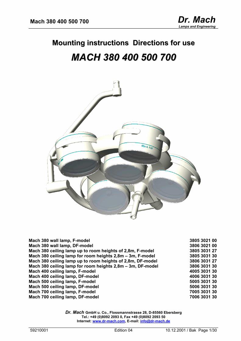
Mach 380 400 500 700 Dr. MachLamps and Engineering
MMoouunnttiinngg iinnssttrruuccttiioonnss DDiirreeccttiioonnss ffoorr uussee
MMAACCHH 338800 440000 550000 770000
Mach 380 wall lamp, F-model 3805 3021 00 Mach 380 wall lamp, DF-model 3806 3021 00 Mach 380 ceiling lamp up to room heights of 2,8m, F-model 3805 3031 27 Mach 380 ceiling lamp for room heights 2,8m – 3m, F-model 3805 3031 30 Mach 380 ceiling lamp up to room heights of 2,8m, DF-model 3806 3031 27 Mach 380 ceiling lamp for room heights 2,8m – 3m, DF-model 3806 3031 30 Mach 400 ceiling lamp, F-model 4005 3031 30 Mach 400 ceiling lamp, DF-model 4006 3031 30 Mach 500 ceiling lamp, F-model 5005 3031 30 Mach 500 ceiling lamp, DF-model 5006 3031 30 Mach 700 ceiling lamp, F-model 7005 3031 30 Mach 700 ceiling lamp, DF-model 7006 3031 30
Dr. Mach GmbH u. Co., Flossmannstrasse 28, D-85560 Ebersberg Tel.: +49 (0)8092 2093 0, Fax +49 (0)8092 2093 50
Internet: www.dr-mach.com, E-mail: [email protected]
59210001 Edition 04 10.12.2001 / Bak Page 1/30
Mach 380 400 500 700 Dr. MachLamps and Engineering
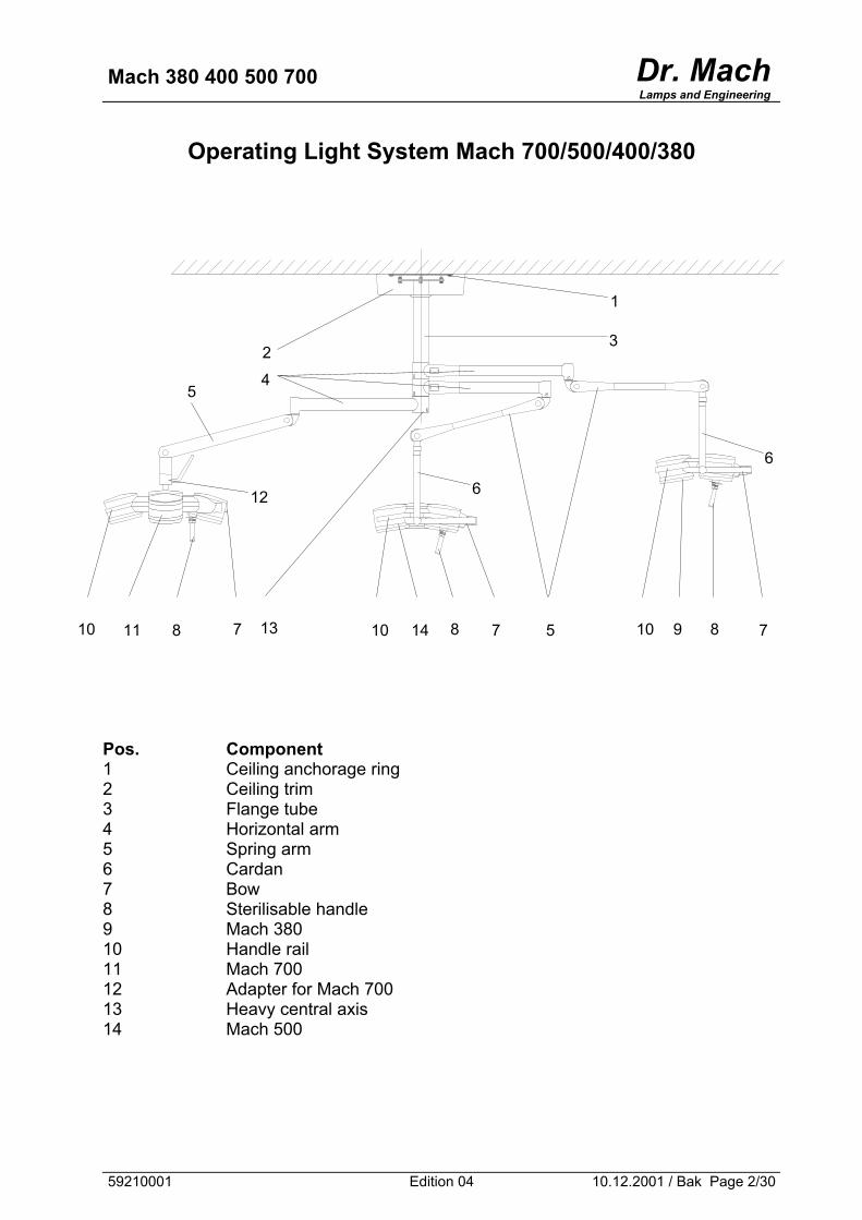
Operating Light System Mach 700/500/400/380
1
3 2
4 5
6
612
13 10 9 810 7 8 711 8 10 14 7 5 Pos. Component 1 Ceiling anchorage ring 2 Ceiling trim 3 Flange tube 4 Horizontal arm 5 Spring arm 6 Cardan 7 Bow 8 Sterilisable handle 9 Mach 380 10 Handle rail 11 Mach 700 12 Adapter for Mach 700 13 Heavy central axis 14 Mach 500
59210001 Edition 04 10.12.2001 / Bak Page 2/30
Mach 380 400 500 700 Dr. MachLamps and Engineering
List of contents
1. Safety instructions ....................................................................................Page 5 2. Operating the MACH-lamps......................................................................Page 6
2.1 Brief description of the light-models ...................................................Page 6 2.1.1 Merging of light fields (F- model).................................................Page 6 2.1.2 Focusing (DF- model) .................................................................Page 6 2.1.3 Auto-Focus (AF- model) ..............................................................Page 7 2.1.4 Light intensity control (/H- model)................................................Page 7
2.2 Adjusting the illuminated field, Duo-Focus system .............................Page 8 2.3 Auto-Focus (AF) .................................................................................Page 9 2.4 Adjusting the light intensity .................................................................Page 10
2.4.1 Voltage measurment at the halogen bulbs ..................................Page 10 2.4.2 Voltage setting at the halogen bulbs ...........................................Page 11 2.4.3 Voltage measurement at the control board .................................Page 11 2.4.4 Voltage setting at the control board.............................................Page 11 2.4.5 Possible settings of the diameter ................................................Page 12 of the focussed light field for the lamps with control boards of version beginning with V 0.70 2.4.6 Adjusting the light intensity..........................................................Page 13
2.5 Sterilisable handle ..............................................................................Page 14 2.6 Positioning..........................................................................................Page 16
3. Cleaning ...................................................................................................Page 17
3.1 Handle ................................................................................................Page 17 3.2 Lamp housing, dispersing lens and support system...........................Page 17
4. Maintenance .............................................................................................Page 18
4.1 Adjustments at the lamp head ............................................................Page 18 4.2 Changing of spare parts .....................................................................Page 19
4.2.1 Changing the halogen bulbs........................................................Page 19 4.2.2 Changing the dispersing lens ......................................................Page 20
5. Data..........................................................................................................Page 21
5.1 Electrical data.....................................................................................Page 21 5.2 Environmental conditions ...................................................................Page 21
6. CE-mark ...................................................................................................Page 21 7. Disposal....................................................................................................Page 21 8. Spare parts ...............................................................................................Page 22 9. Spare parts list..........................................................................................Page 26 10. Appendix: Setting the primary voltage at the block transformer
300VA (extra) ........................................................................page 28
59210001 Edition 04 10.12.2001 / Bak Page 3/30
Mach 380 400 500 700 Dr. MachLamps and Engineering
Dear customer! You have just bought a product from the New Generation of MACH lamps. The new MachVISION optical system provides an illuminated field with improved contrast and excellent homogeneity. Combined with the Duo-Focus feature this offers a unique possibility for adaptation to the wound area. With this lighting system you profit from a whole range of new developments, based on 50 years of experience in the production of operating and doctor's lights. The lighting system is characterised by a previously inconceivable general colour rendition value of Ra = 96. In other words, the colours are reproduced naturally and in high contrast. The wound area is shown in a comfortable light. The different reds of a wound area can now be recognised very precisely. For the doctor or sur-geon this means a considerable improvement in the recognition of details in the wound area. The R96 lighting system uses computer-optimised cold-light filters that reduce both the un-wanted build-up of heat in the head area and the heat radiated on the illuminated wound area to a minimum. Pay attention to the special mounting instructions for ceiling and wall lamps. All information quoted here relates only to the illuminants. Details of ceiling or wall installation can be found in the mounting instructions
59210001 Edition 04 10.12.2001 / Bak Page 4/30
Mach 380 400 500 700 Dr. MachLamps and Engineering
1. Safety instructions
Pay attention to the instructions for use when handling the lamp.
Warning:
This device has not been designed for use in potentially explosive areas. The lamp is classified as Group 1 according to the Medical Device Regulation.
Store the OT-lamp in its package for at least 24 hours in the respective room
before mounting, in order to equal temperature differences. Please read the instructions for use carefully to make the most of your lighting sys-tem and to avoid any damages to the device. The lamps may only be repaired and special assembly work may only be carried out on the reflector or sockets by ourselves or a company that has been expressly authorised by us. The manufacturer can only be made responsible for the safety of the lamp if repairs and alterations are carried out by the manufacturer himself or a company that guaran-tees to observe the safety regulations. The manufacturer cannot be made liable for personal or material damages if the lamp is operated inexpediently or incorrectly or used for purposes other than those for which it is intended. The lamp is to be dismantled from the spring arm (wall and ceiling model) in reverse order to its assembly. This may only be carried out after the assembly-locking device has been inserted and secured since the arm is under spring tension.
Make sure that the lamp is in perfect working order before every use.
59210001 Edition 04 10.12.2001 / Bak Page 5/30
Mach 380 400 500 700 Dr. MachLamps and Engineering
2. Operating the lamps Mach 380 / 400 / 500 / 700
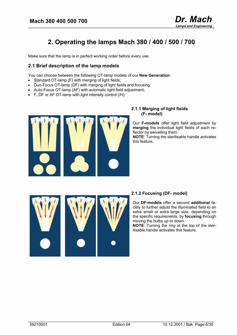
Make sure that the lamp is in perfect working order before every use. 2.1 Brief description of the lamp models You can choose between the following OT-lamp models of our New Generation: • Standard OT-lamp (F) with merging of light fields; • Duo-Focus OT-lamp (DF) with merging of light fields and focusing; • Auto-Focus OT-lamp (AF) with automatic light field adjustment; • F, DF or AF OT-lamp with light intensity control (/H)
2.1.1 Merging of light fields
(F- model) Our F-models offer light field adjustment by merging the individual light fields of each re-flector by swivelling them. NOTE: Turning the sterilisable handle activates this feature.
2.1.2 Focusing (DF- model) Our DF-models offer a second additional fa-cility to further adjust the illuminated field to an extra small or extra large size, depending on the specific requirements, by focusing through moving the bulbs up or down. NOTE: Turning the ring at the top of the ster-ilisable handle activates this feature.
59210001 Edition 04 10.12.2001 / Bak Page 6/30
Mach 380 400 500 700 Dr. MachLamps and Engineering
Automatical light field adjustment
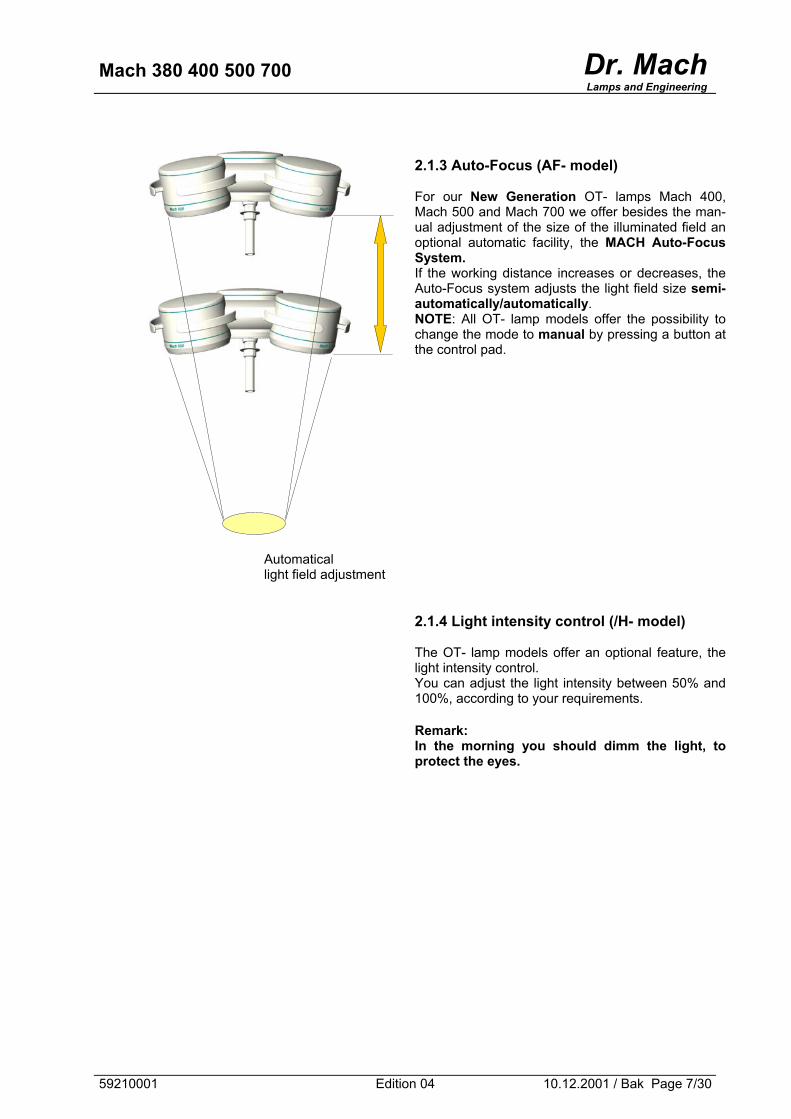
2.1.3 Auto-Focus (AF- model) For our New Generation OT- lamps Mach 400, Mach 500 and Mach 700 we offer besides the man-ual adjustment of the size of the illuminated field an optional automatic facility, the MACH Auto-Focus System. If the working distance increases or decreases, the Auto-Focus system adjusts the light field size semi-automatically/automatically. NOTE: All OT- lamp models offer the possibility to change the mode to manual by pressing a button at the control pad.
2.1.4 Light intensity control (/H- model) The OT- lamp models offer an optional feature, the light intensity control. You can adjust the light intensity between 50% and 100%, according to your requirements. Remark: In the morning you should dimm the light, to protect the eyes.
59210001 Edition 04 10.12.2001 / Bak Page 7/30
Mach 380 400 500 700 Dr. MachLamps and Engineering
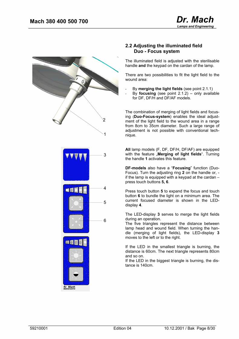
2.2 Adjusting the illuminated field
Duo - Focus system The illuminated field is adjusted with the sterilisable handle and the keypad on the cardan of the lamp. There are two possibilities to fit the light field to the wound area: - By merging the light fields (see point 2.1.1) - By focusing (see point 2.1.2) – only available
for DF, DF/H and DF/AF models. The combination of merging of light fields and focus-ing (Duo-Focus-system) enables the ideal adjust-ment of the light field to the wound area in a range from 8cm to 35cm diameter. Such a large range of adjustment is not possible with conventional tech-nique.
All lamp models (F, DF, DF/H, DF/AF) are equipped with the feature „Merging of light fields“. Turning the handle 1 activates this feature. DF-models also have a “Focusing” function (Duo-Focus). Turn the adjusting ring 2 on the handle or, - if the lamp is equipped with a keypad at the cardan – press touch buttons 5, 6. Press touch button 5 to expand the focus and touch button 6 to bundle the light on a minimum area. The current focused diameter is shown in the LED-display 4. The LED-display 3 serves to merge the light fields during an operation. The five triangles represent the distance between lamp head and wound field. When turning the han-dle (merging of light fields), the LED-display 3 moves to the left or to the right. If the LED in the smallest triangle is burning, the distance is 60cm. The next triangle represents 80cm and so on. If the LED in the biggest triangle is burning, the dis-tance is 140cm.
1
2
3
4
5
6
59210001 Edition 04 10.12.2001 / Bak Page 8/30

Mach 380 400 500 700 Dr. MachLamps and Engineering
2.3 Auto-Focus (AF) In case of OT-lamps equipped with Auto-Focus system, the adjusting of the lamp after a change of work-ing distance is done automatically, that means, merging of light fields (not focusing!!!) is done automati-cally. The dfferences between merging of light fields and focusing are explained at point 2.1.1 and 2.1.2. The Auto-Focus system provides three alternative operating modes: • Manual mode • Semi-automatic mode • Fully-automatic mode
I) MANUAL mode When the lamp is switched on, the MANUAL mode is set. The control lamp at the touch button 1 is off. Merging of the light fields can be obtained manually by turning the ster-ilizable handle 4. You can change the mode to SEMI-AUTOMATIC or FULLY-AUTOMATIC. II) SEMI-AUTOMATIC mode To change the mode to SEMI-AUTOMATIC press touch button 1 for about 2 seconds (the control lamp at the touch button 1 turns on). The semi-automatic mode is activated by a quick turn of the sterilisable handle 4. The light fields merge automatically. In case of another change of the distance between OT-lamp and wound field, proceed the same way for a automatical adjustment of the light fields. The mode can be changed to MANUAL by pressing push button 1, so that the control lamp at touch button 1 turns off. III) FULLY-AUTOMATIC mode To change the mode to FULLY-AUTOMATIC press push buttons 1 and 2 simultaneously for about 2 seconds (the control lamp at the touch button 1 is blinking). The setting for the working distance is done fully automatic. It is not nec-essary anymore to turn the handle again in case of a change of the work-ing distance. If the working distance is changing, the automatic function is activated after a few seconds. This is necessary for avoiding and excluding any kind of irritations caused by moving hands and instruments in the area of the sensor. The sterilisable handle 4 has no function in this mode. The ring 3 at the sterilisable handle can be used to adjust the focus by hand. PLEASE TAKE NOTICE: In case of tight and very deep wound areas do not use FULLY-AUTMATIC mode.
3
4
59210001 Edition 04 10.12.2001 / Bak Page 9/30
Mach 380 400 500 700 Dr. MachLamps and Engineering
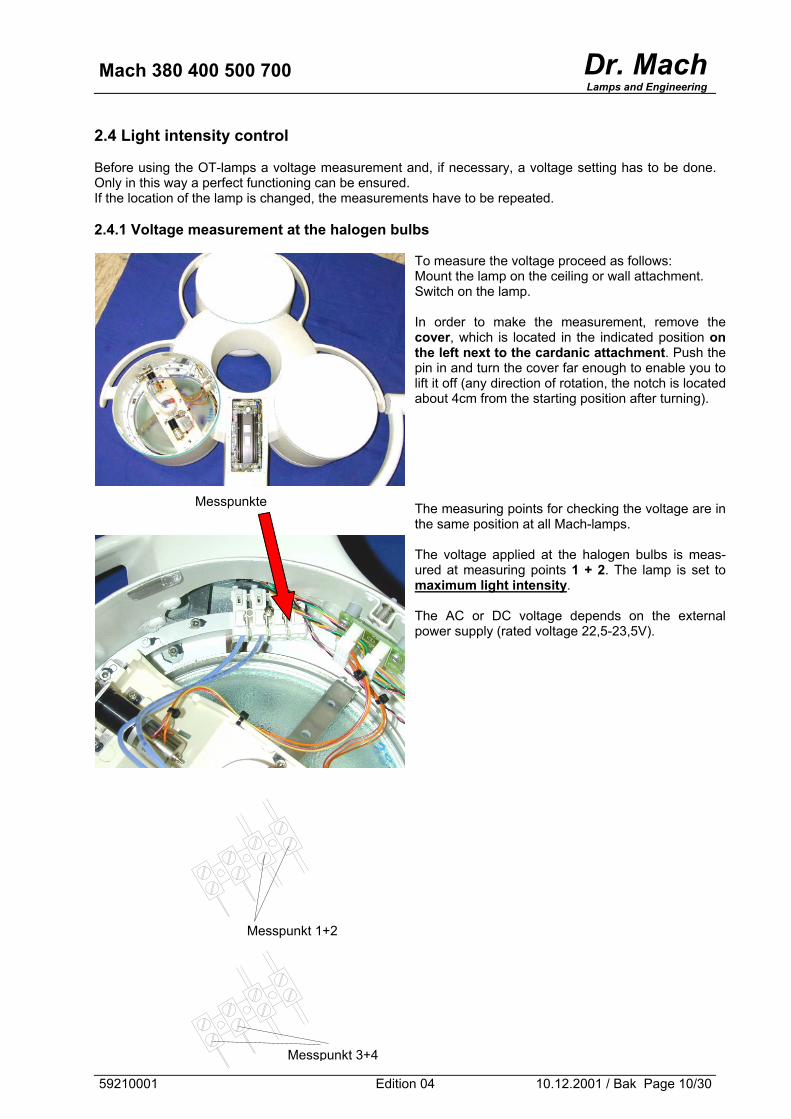
2.4 Light intensity control Before using the OT-lamps a voltage measurement and, if necessary, a voltage setting has to be done. Only in this way a perfect functioning can be ensured. If the location of the lamp is changed, the measurements have to be repeated. 2.4.1 Voltage measurement at the halogen bulbs
To measure the voltage proceed as follows: Mount the lamp on the ceiling or wall attachment. Switch on the lamp. In order to make the measurement, remove the cover, which is located in the indicated position on the left next to the cardanic attachment. Push the pin in and turn the cover far enough to enable you to lift it off (any direction of rotation, the notch is located about 4cm from the starting position after turning).
The measuring points for checking the voltage are in the same position at all Mach-lamps. The voltage applied at the halogen bulbs is meas-ured at measuring points 1 + 2. The lamp is set to maximum light intensity. The AC or DC voltage depends on the external power supply (rated voltage 22,5-23,5V).
Messpunkte
Messpunkt 1+2
Messpunkt 3+4
59210001 Edition 04 10.12.2001 / Bak Page 10/30
Mach 380 400 500 700 Dr. MachLamps and Engineering
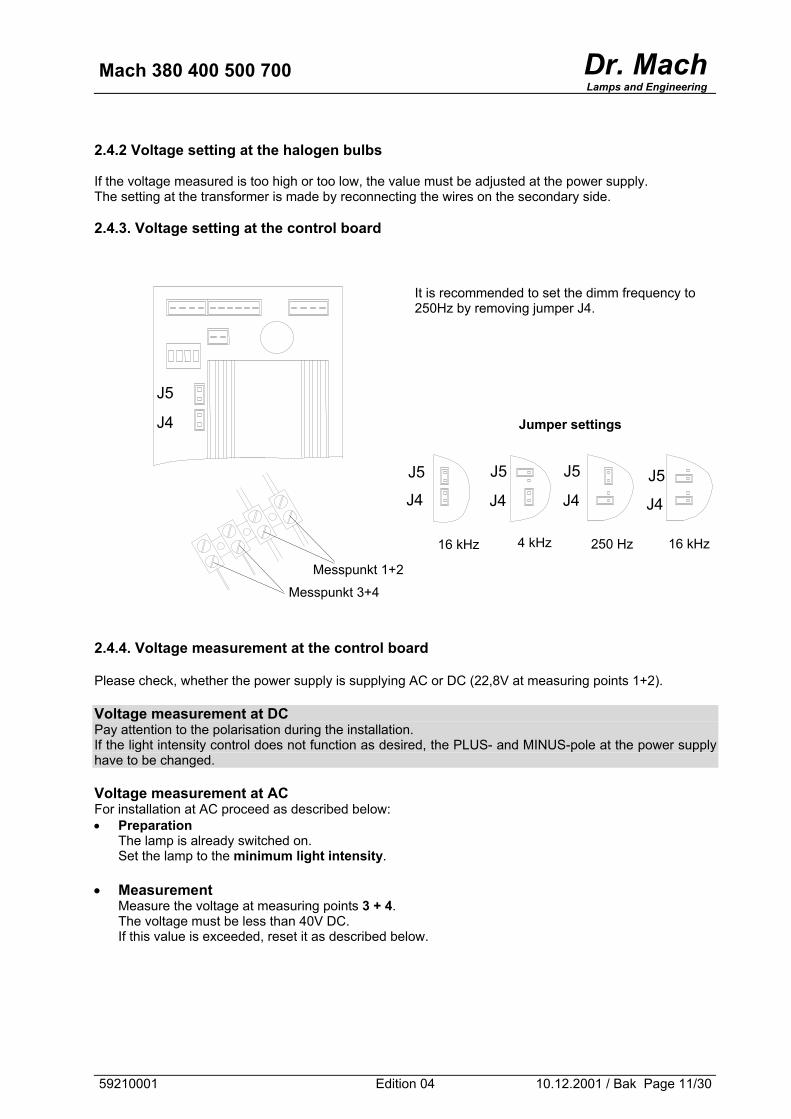
2.4.2 Voltage setting at the halogen bulbs If the voltage measured is too high or too low, the value must be adjusted at the power supply. The setting at the transformer is made by reconnecting the wires on the secondary side. 2.4.3. Voltage setting at the control board
It is recommended to set the dimm frequency to 250Hz by removing jumper J4.
Jumper settings
J5
J4
J5 J5 J5 J5 J4 J4 J4 J4
Messpunkt 1+2
Messpunkt 3+4
4 kHz 16 kHz 250 Hz 16 kHz
2.4.4. Voltage measurement at the control board Please check, whether the power supply is supplying AC or DC (22,8V at measuring points 1+2). Voltage measurement at DC Pay attention to the polarisation during the installation. If the light intensity control does not function as desired, the PLUS- and MINUS-pole at the power supply have to be changed. Voltage measurement at AC For installation at AC proceed as described below: • Preparation
The lamp is already switched on. Set the lamp to the minimum light intensity.
• Measurement
Measure the voltage at measuring points 3 + 4. The voltage must be less than 40V DC. If this value is exceeded, reset it as described below.
59210001 Edition 04 10.12.2001 / Bak Page 11/30
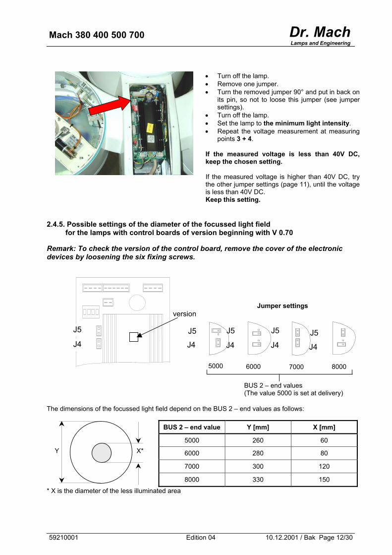
Mach 380 400 500 700 Dr. MachLamps and Engineering
• Turn off the lamp. • Remove one jumper. • Turn the removed jumper 90° and put in back on
its pin, so not to loose this jumper (see jumper settings).
• Turn off the lamp. • Set the lamp to the minimum light intensity. • Repeat the voltage measurement at measuring
points 3 + 4. If the measured voltage is less than 40V DC, keep the chosen setting. If the measured voltage is higher than 40V DC, try the other jumper settings (page 11), until the voltage is less than 40V DC. Keep this setting.
2.4.5. Possible settings of the diameter of the focussed light field
for the lamps with control boards of version beginning with V 0.70 Remark: To check the version of the control board, remove the cover of the electronic devices by loosening the six fixing screws.
Jumper settings
J4
J5
version
J5 J5 J5 J5 J4 J4 J4 J4
7000 5000 8000 6000
BUS 2 – end values (The value 5000 is set at delivery)
The dimensions of the focussed light field depend on the BUS 2 – end values as follows:
BUS 2 – end value Y [mm] X [mm]
5000 260 60
6000 280 80
7000 300 120
8000 330 150
Y X*
* X is the diameter of the less illuminated area
59210001 Edition 04 10.12.2001 / Bak Page 12/30
Mach 380 400 500 700 Dr. MachLamps and Engineering
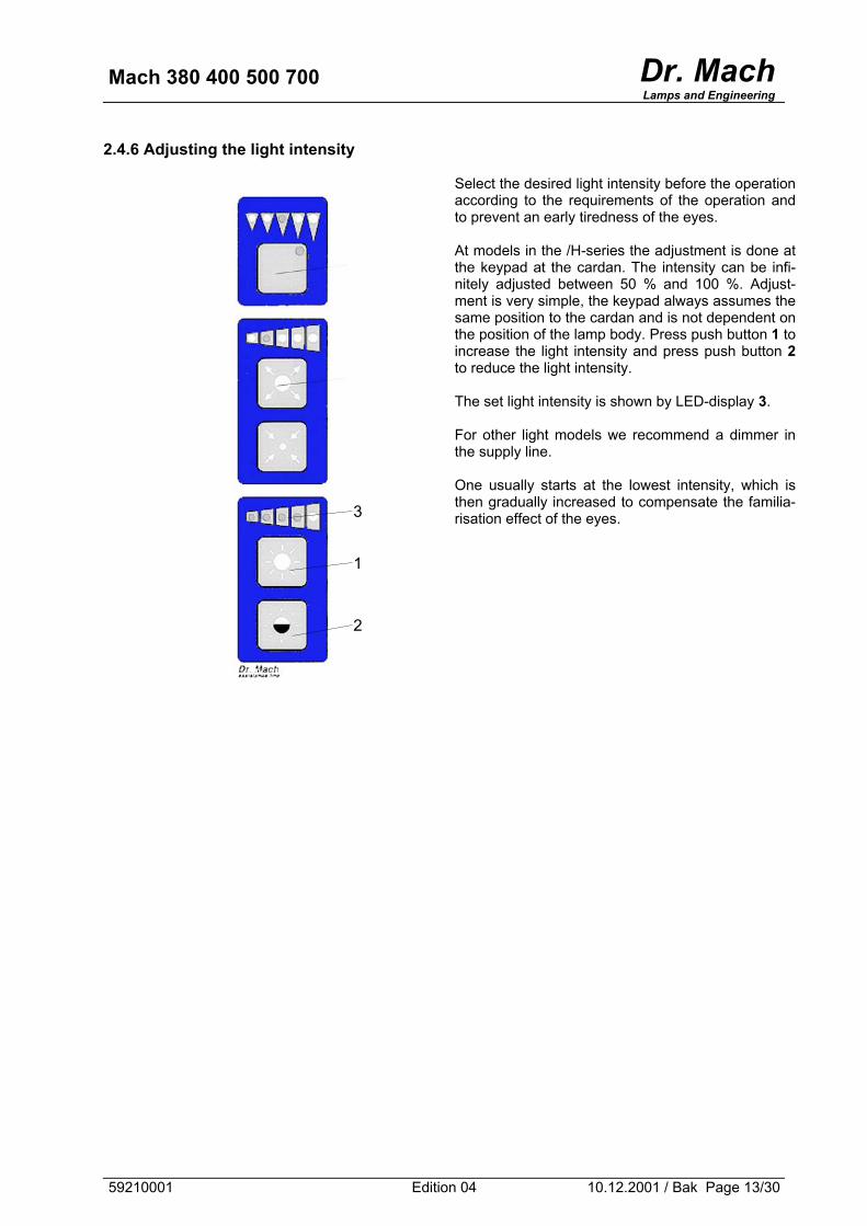
2.4.6 Adjusting the light intensity
Select the desired light intensity before the operation according to the requirements of the operation and to prevent an early tiredness of the eyes. At models in the /H-series the adjustment is done at the keypad at the cardan. The intensity can be infi-nitely adjusted between 50 % and 100 %. Adjust-ment is very simple, the keypad always assumes the same position to the cardan and is not dependent on the position of the lamp body. Press push button 1 to increase the light intensity and press push button 2 to reduce the light intensity. The set light intensity is shown by LED-display 3. For other light models we recommend a dimmer in the supply line. One usually starts at the lowest intensity, which is then gradually increased to compensate the familia-risation effect of the eyes.
3
1
2
59210001 Edition 04 10.12.2001 / Bak Page 13/30
Mach 380 400 500 700 Dr. MachLamps and Engineering
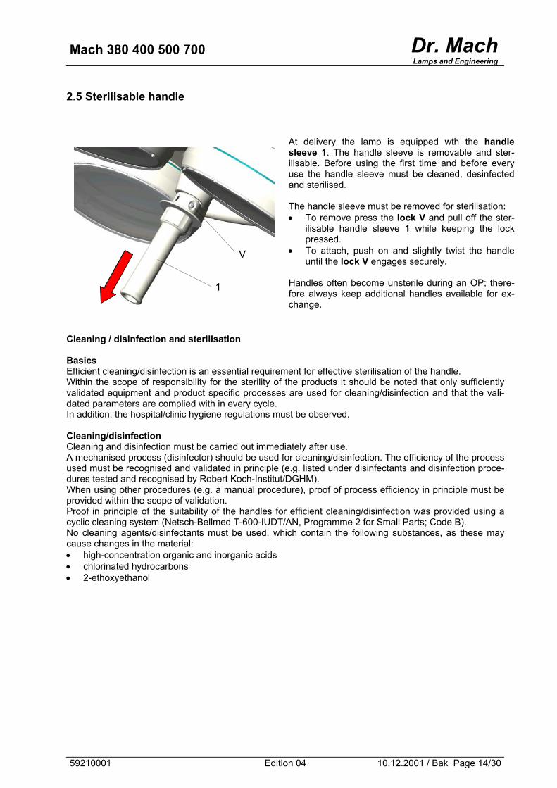
2.5 Sterilisable handle
At delivery the lamp is equipped wth the handle sleeve 1. The handle sleeve is removable and ster-ilisable. Before using the first time and before every use the handle sleeve must be cleaned, desinfected and sterilised. The handle sleeve must be removed for sterilisation: • To remove press the lock V and pull off the ster-
ilisable handle sleeve 1 while keeping the lock pressed.
• To attach, push on and slightly twist the handle until the lock V engages securely.
Handles often become unsterile during an OP; there-fore always keep additional handles available for ex-change.
V
1
Cleaning / disinfection and sterilisation Basics Efficient cleaning/disinfection is an essential requirement for effective sterilisation of the handle. Within the scope of responsibility for the sterility of the products it should be noted that only sufficiently validated equipment and product specific processes are used for cleaning/disinfection and that the vali-dated parameters are complied with in every cycle. In addition, the hospital/clinic hygiene regulations must be observed. Cleaning/disinfection Cleaning and disinfection must be carried out immediately after use. A mechanised process (disinfector) should be used for cleaning/disinfection. The efficiency of the process used must be recognised and validated in principle (e.g. listed under disinfectants and disinfection proce-dures tested and recognised by Robert Koch-Institut/DGHM). When using other procedures (e.g. a manual procedure), proof of process efficiency in principle must be provided within the scope of validation. Proof in principle of the suitability of the handles for efficient cleaning/disinfection was provided using a cyclic cleaning system (Netsch-Bellmed T-600-IUDT/AN, Programme 2 for Small Parts; Code B). No cleaning agents/disinfectants must be used, which contain the following substances, as these may cause changes in the material: • high-concentration organic and inorganic acids • chlorinated hydrocarbons • 2-ethoxyethanol
59210001 Edition 04 10.12.2001 / Bak Page 14/30
Mach 380 400 500 700 Dr. MachLamps and Engineering
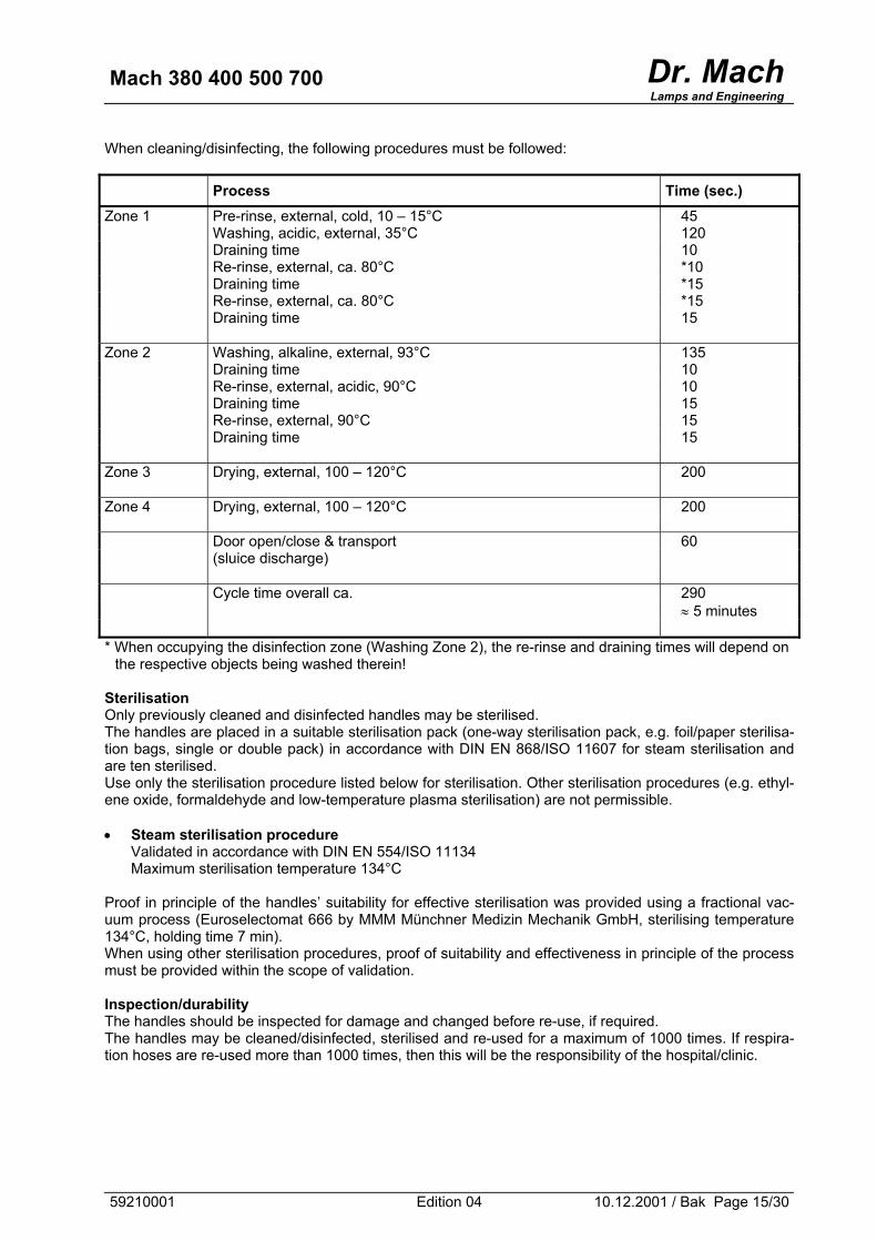
When cleaning/disinfecting, the following procedures must be followed:
Process Time (sec.) Zone 1 Pre-rinse, external, cold, 10 – 15°C 45 Washing, acidic, external, 35°C 120 Draining time 10 Re-rinse, external, ca. 80°C *10 Draining time *15 Re-rinse, external, ca. 80°C *15 Draining time 15 Zone 2 Washing, alkaline, external, 93°C 135 Draining time 10 Re-rinse, external, acidic, 90°C 10 Draining time 15 Re-rinse, external, 90°C 15 Draining time 15 Zone 3 Drying, external, 100 – 120°C 200 Zone 4 Drying, external, 100 – 120°C 200 Door open/close & transport 60 (sluice discharge) Cycle time overall ca. 290 ≈ 5 minutes * When occupying the disinfection zone (Washing Zone 2), the re-rinse and draining times will depend on
the respective objects being washed therein! Sterilisation Only previously cleaned and disinfected handles may be sterilised. The handles are placed in a suitable sterilisation pack (one-way sterilisation pack, e.g. foil/paper sterilisa-tion bags, single or double pack) in accordance with DIN EN 868/ISO 11607 for steam sterilisation and are ten sterilised. Use only the sterilisation procedure listed below for sterilisation. Other sterilisation procedures (e.g. ethyl-ene oxide, formaldehyde and low-temperature plasma sterilisation) are not permissible. • Steam sterilisation procedure
Validated in accordance with DIN EN 554/ISO 11134 Maximum sterilisation temperature 134°C
Proof in principle of the handles’ suitability for effective sterilisation was provided using a fractional vac-uum process (Euroselectomat 666 by MMM Münchner Medizin Mechanik GmbH, sterilising temperature 134°C, holding time 7 min). When using other sterilisation procedures, proof of suitability and effectiveness in principle of the process must be provided within the scope of validation. Inspection/durability The handles should be inspected for damage and changed before re-use, if required. The handles may be cleaned/disinfected, sterilised and re-used for a maximum of 1000 times. If respira-tion hoses are re-used more than 1000 times, then this will be the responsibility of the hospital/clinic.
59210001 Edition 04 10.12.2001 / Bak Page 15/30
Mach 380 400 500 700 Dr. MachLamps and Engineering
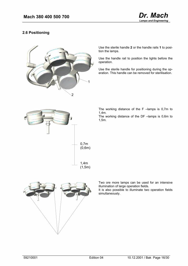
2.6 Positioning
Use the sterile handle 2 or the handle rails 1 to posi-tion the lamps. Use the handle rail to position the lights before the operation. Use the sterile handle for positioning during the op-eration. This handle can be removed for sterilisation.
The working distance of the F –lamps is 0,7m to 1,4m. The working distance of the DF –lamps is 0,6m to 1,5m.
Two ore more lamps can be used for an intensive illumination of large operation fields. It is also possible to illuminate two operation fields simultaneously.
0,7m (0,6m)
1,4m (1,5m)
2
1
59210001 Edition 04 10.12.2001 / Bak Page 16/30
Mach 380 400 500 700 Dr. MachLamps and Engineering
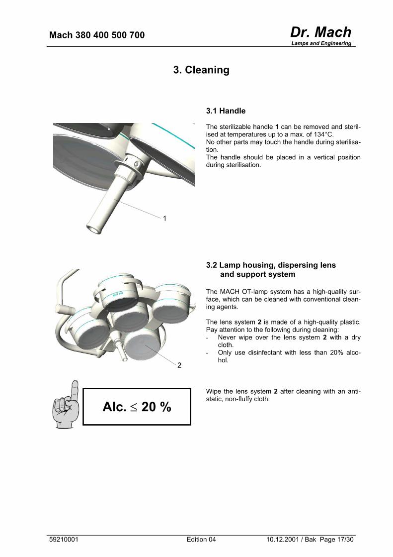
3. Cleaning
3.1 Handle The sterilizable handle 1 can be removed and steril-ised at temperatures up to a max. of 134°C. No other parts may touch the handle during sterilisa-tion. The handle should be placed in a vertical position during sterilisation.
1
3.2 Lamp housing, dispersing lens
and support system The MACH OT-lamp system has a high-quality sur-face, which can be cleaned with conventional clean-ing agents. The lens system 2 is made of a high-quality plastic. Pay attention to the following during cleaning: - Never wipe over the lens system 2 with a dry
cloth. - Only use disinfectant with less than 20% alco-
hol.
Wipe the lens system 2 after cleaning with an anti-static, non-fluffy cloth.
2
Alc. ≤ 20 %
59210001 Edition 04 10.12.2001 / Bak Page 17/30
Mach 380 400 500 700 Dr. MachLamps and Engineering
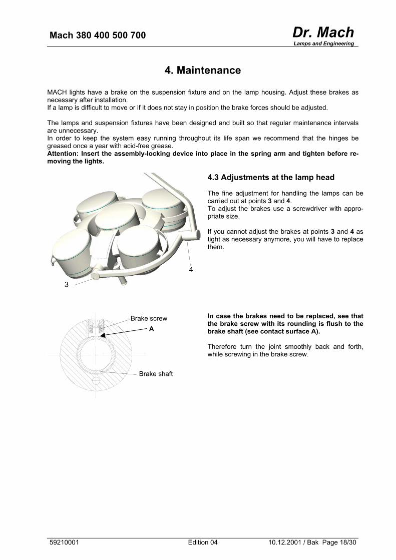
4. Maintenance
MACH lights have a brake on the suspension fixture and on the lamp housing. Adjust these brakes as necessary after installation. If a lamp is difficult to move or if it does not stay in position the brake forces should be adjusted. The lamps and suspension fixtures have been designed and built so that regular maintenance intervals are unnecessary. In order to keep the system easy running throughout its life span we recommend that the hinges be greased once a year with acid-free grease. Attention: Insert the assembly-locking device into place in the spring arm and tighten before re-moving the lights.
4.3 Adjustments at the lamp head The fine adjustment for handling the lamps can be carried out at points 3 and 4. To adjust the brakes use a screwdriver with appro-priate size. If you cannot adjust the brakes at points 3 and 4 as tight as necessary anymore, you will have to replace them.
In case the brakes need to be replaced, see that the brake screw with its rounding is flush to the brake shaft (see contact surface A). Therefore turn the joint smoothly back and forth, while screwing in the brake screw.
4
3
Brake screw A
Brake shaft
59210001 Edition 04 10.12.2001 / Bak Page 18/30
Mach 380 400 500 700 Dr. MachLamps and Engineering
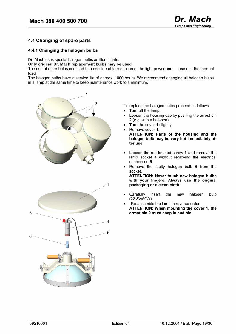
4.4 Changing of spare parts 4.4.1 Changing the halogen bulbs Dr. Mach uses special halogen bulbs as illuminants. Only original Dr. Mach replacement bulbs may be used. The use of other bulbs can lead to a considerable reduction of the light power and increase in the thermal load. The halogen bulbs have a service life of approx. 1000 hours. We recommend changing all halogen bulbs in a lamp at the same time to keep maintenance work to a minimum.
To replace the halogen bulbs proceed as follows: • Turn off the lamp. • Loosen the housing cap by pushing the arrest pin
2 (e.g. with a ball-pen). • Turn the cover 1 slightly. • Remove cover 1.
ATTENTION: Parts of the housing and the halogen bulb may be very hot immediately af-ter use.
• Loosen the red knurled screw 3 and remove the
lamp socket 4 without removing the electrical connection 5.
• Remove the faulty halogen bulb 6 from the socket. ATTENTION: Never touch new halogen bulbs with your fingers. Always use the original packaging or a clean cloth.
• Carefully insert the new halogen bulb
(22.8V/50W). • Re-assemble the lamp in reverse order
ATTENTION: When mounting the cover 1, the arrest pin 2 must snap in audible.
1
2
1
3
4
5 6
59210001 Edition 04 10.12.2001 / Bak Page 19/30
Mach 380 400 500 700 Dr. MachLamps and Engineering
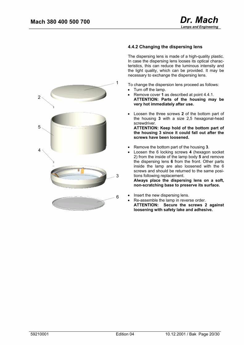
4.4.2 Changing the dispersing lens The dispersing lens is made of a high-quality plastic. In case the dispersing lens looses its optical charac-teristics, this can reduce the luminous intensity and the light quality, which can be provided. It may be necessary to exchange the dispersing lens. To change the dispersion lens proceed as follows: • Turn off the lamp. • Remove cover 1 as described at point 4.4.1.
ATTENTION: Parts of the housing may be very hot immediately after use.
• Loosen the three screws 2 of the bottom part of
the housing 3 with a size 2,5 hexagonal-head screwdriver. ATTENTION: Keep hold of the bottom part of the housing 3 since it could fall out after the screws have been loosened.
• Remove the bottom part of the housing 3. • Loosen the 6 locking screws 4 (hexagon socket
2) from the inside of the lamp body 5 and remove the dispersing lens 6 from the front. Other parts inside the lamp are also loosened with the 6 screws and should be returned to the same posi-tions following replacement. Always place the dispersing lens on a soft, non-scratching base to preserve its surface.
• Insert the new dispersing lens. • Re-assemble the lamp in reverse order.
ATTENTION: Secure the screws 2 against loosening with safety lake and adhesive.
1
2
5
4
3
6
59210001 Edition 04 10.12.2001 / Bak Page 20/30
Mach 380 400 500 700 Dr. MachLamps and Engineering
5. Data
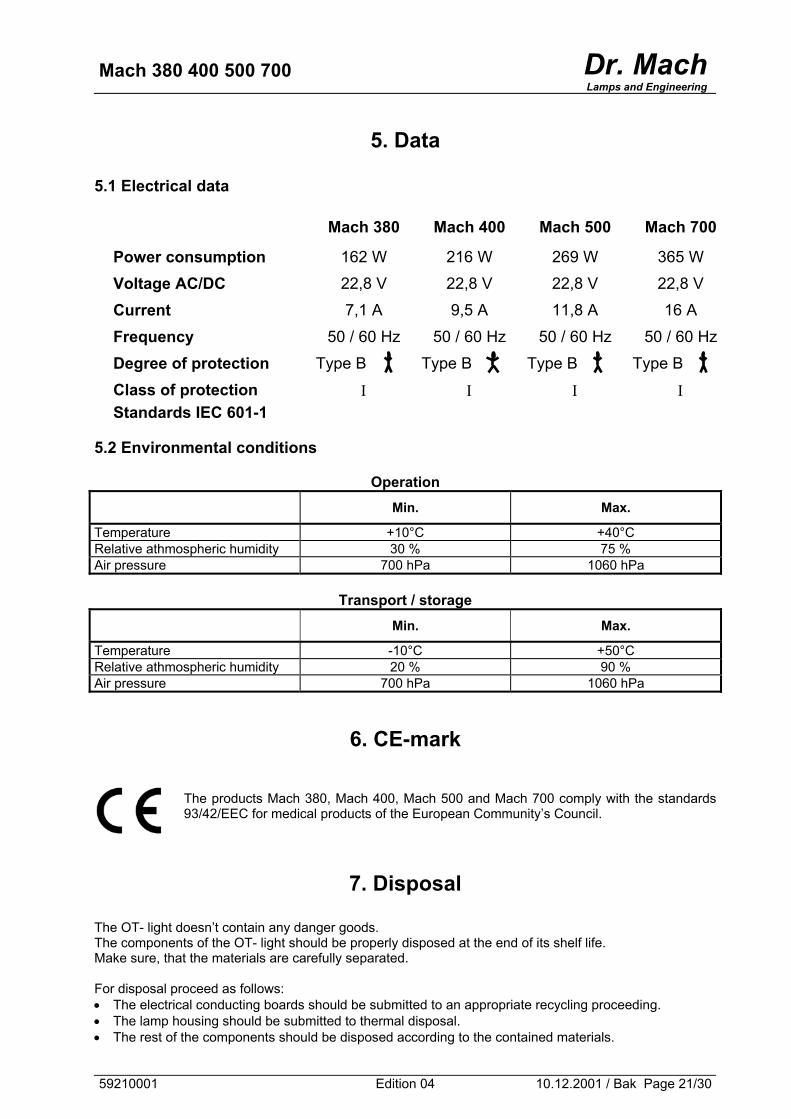
5.1 Electrical data
Mach 380 Mach 400 Mach 500 Mach 700
Power consumption 162 W 216 W 269 W 365 W
Voltage AC/DC 22,8 V 22,8 V 22,8 V 22,8 V
Current 7,1 A 9,5 A 11,8 A 16 A
Frequency 50 / 60 Hz 50 / 60 Hz 50 / 60 Hz 50 / 60 Hz
Degree of protection Type B Type B Type B Type B
Class of protection Ι Ι Ι Ι Standards IEC 601-1
5.2 Environmental conditions
Operation Min. Max.
Temperature +10°C +40°C Relative athmospheric humidity 30 % 75 % Air pressure 700 hPa 1060 hPa
Transport / storage Min. Max.
Temperature -10°C +50°C Relative athmospheric humidity 20 % 90 % Air pressure 700 hPa 1060 hPa
6. CE-mark
The products Mach 380, Mach 400, Mach 500 and Mach 700 comply with the standards 93/42/EEC for medical products of the European Community’s Council.
7. Disposal
The OT- light doesn’t contain any danger goods. The components of the OT- light should be properly disposed at the end of its shelf life. Make sure, that the materials are carefully separated. For disposal proceed as follows: • The electrical conducting boards should be submitted to an appropriate recycling proceeding. • The lamp housing should be submitted to thermal disposal. • The rest of the components should be disposed according to the contained materials.
59210001 Edition 04 10.12.2001 / Bak Page 21/30
Mach 380 400 500 700 Dr. MachLamps and Engineering
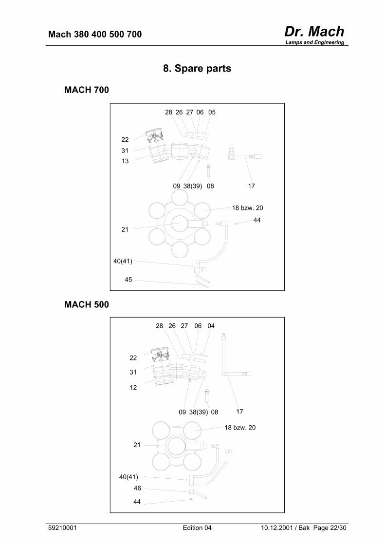
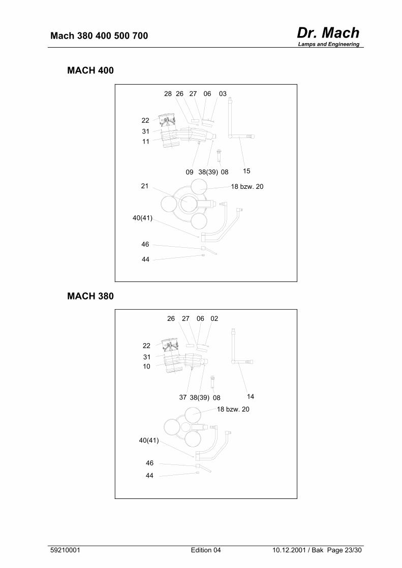
8. Spare parts
MACH 700
28 26 27 06 05
22
31 13
09 38(39) 08 17
18 bzw. 20
4421
40(41)
45
MACH 500
46
44
40(41)
21
18 bzw. 20
12
31
22
1738(39) 0809
0406272628
59210001 Edition 04 10.12.2001 / Bak Page 22/30
Mach 380 400 500 700 Dr. MachLamps and Engineering
MACH 400
28 26 27 06 03
22 31 11
1538(39) 0809
21 18 bzw. 20
40(41)
46
44
MACH 380
44
46
18 bzw. 20
140838(39)37
40(41)
10 31
22
02062726
59210001 Edition 04 10.12.2001 / Bak Page 23/30
Mach 380 400 500 700 Dr. MachLamps and Engineering
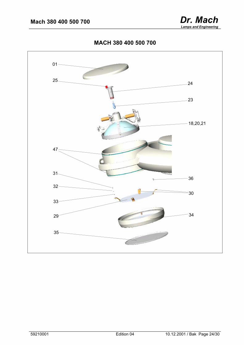
MACH 380 400 500 700
23
24
35
29
33
31
32
47
25
01
18,20,21
36
30
34
59210001 Edition 04 10.12.2001 / Bak Page 24/30

Mach 380 400 500 700 Dr. MachLamps and Engineering
Reflector units
DF
External reflector unit, DF-model
F
Lateral reflector unit, F-model
FZ
Lateral reflector unit, DF- and F-model
(Mach 400, 500, 700)
43 42
18
42
20
21
59210001 Edition 04 10.12.2001 / Bak Page 25/30
Mach 380 400 500 700 Dr. MachLamps and Engineering
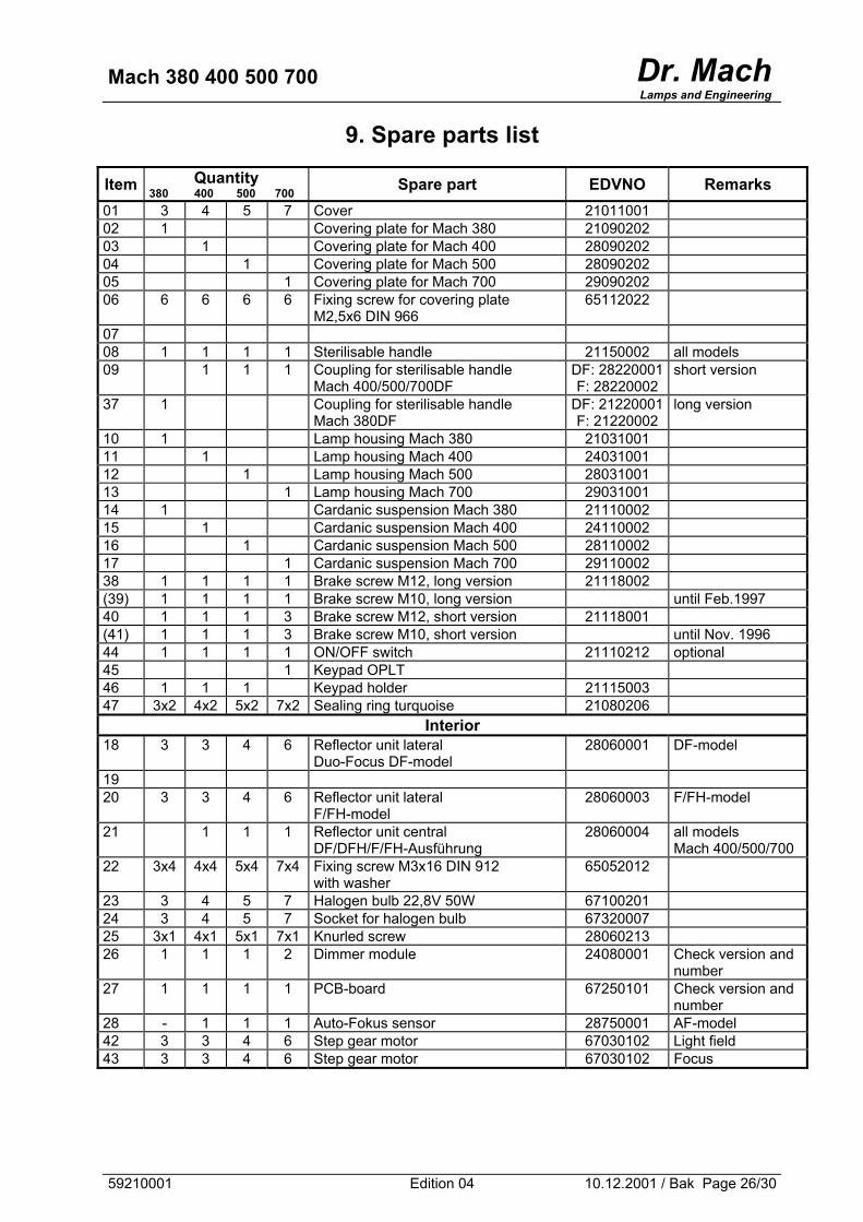
9. Spare parts list
Item Quantity 380 400 500 700 Spare part EDVNO Remarks
01 3 4 5 7 Cover 21011001 02 1 Covering plate for Mach 380 21090202 03 1 Covering plate for Mach 400 28090202 04 1 Covering plate for Mach 500 28090202 05 1 Covering plate for Mach 700 29090202 06 6 6 6 6 Fixing screw for covering plate
M2,5x6 DIN 966 65112022
07 08 1 1 1 1 Sterilisable handle 21150002 all models 09 1 1 1 Coupling for sterilisable handle
Mach 400/500/700DF DF: 28220001 F: 28220002
short version
37 1 Coupling for sterilisable handle Mach 380DF
DF: 21220001 F: 21220002
long version
10 1 Lamp housing Mach 380 21031001 11 1 Lamp housing Mach 400 24031001 12 1 Lamp housing Mach 500 28031001 13 1 Lamp housing Mach 700 29031001 14 1 Cardanic suspension Mach 380 21110002 15 1 Cardanic suspension Mach 400 24110002 16 1 Cardanic suspension Mach 500 28110002 17 1 Cardanic suspension Mach 700 29110002 38 1 1 1 1 Brake screw M12, long version 21118002 (39) 1 1 1 1 Brake screw M10, long version until Feb.1997 40 1 1 1 3 Brake screw M12, short version 21118001 (41) 1 1 1 3 Brake screw M10, short version until Nov. 1996 44 1 1 1 1 ON/OFF switch 21110212 optional 45 1 Keypad OPLT 46 1 1 1 Keypad holder 21115003 47 3x2 4x2 5x2 7x2 Sealing ring turquoise 21080206
Interior 18 3 3 4 6 Reflector unit lateral
Duo-Focus DF-model 28060001 DF-model
19 20 3 3 4 6 Reflector unit lateral
F/FH-model 28060003 F/FH-model
21 1 1 1 Reflector unit central DF/DFH/F/FH-Ausführung
28060004 all models Mach 400/500/700
22 3x4 4x4 5x4 7x4 Fixing screw M3x16 DIN 912 with washer
65052012
23 3 4 5 7 Halogen bulb 22,8V 50W 67100201 24 3 4 5 7 Socket for halogen bulb 67320007 25 3x1 4x1 5x1 7x1 Knurled screw 28060213 26 1 1 1 2 Dimmer module 24080001 Check version and
number 27 1 1 1 1 PCB-board 67250101 Check version and
number 28 - 1 1 1 Auto-Fokus sensor 28750001 AF-model 42 3 3 4 6 Step gear motor 67030102 Light field 43 3 3 4 6 Step gear motor 67030102 Focus
59210001 Edition 04 10.12.2001 / Bak Page 26/30
Mach 380 400 500 700 Dr. MachLamps and Engineering
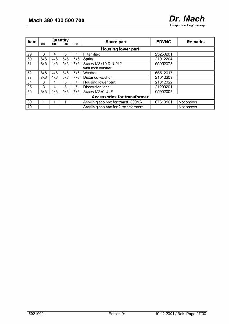
Item Quantity 380 400 500 700 Spare part EDVNO Remarks
Housing lower part 29 3 4 5 7 Filter disk 23250201 30 3x3 4x3 5x3 7x3 Spring 21012204 31 3x6 4x6 5x6 7x6 Screw M3x10 DIN 912
with lock washer 65052078
32 3x6 4x6 5x6 7x6 Washer 65512017 33 3x6 4x6 5x6 7x6 Distance washer 21012203 34 3 4 5 7 Housing lower part 21012022 35 3 4 5 7 Dispersion lens 21200201 36 3x3 4x3 5x3 7x3 Screw M3x6 ULF 65902003
Accessories for transformer 39 1 1 1 Acrylic glass box for transf. 300VA 67610101 Not shown 40 Acrylic glass box for 2 transformers Not shown
59210001 Edition 04 10.12.2001 / Bak Page 27/30
Mach 380 400 500 700 Dr. MachLamps and Engineering
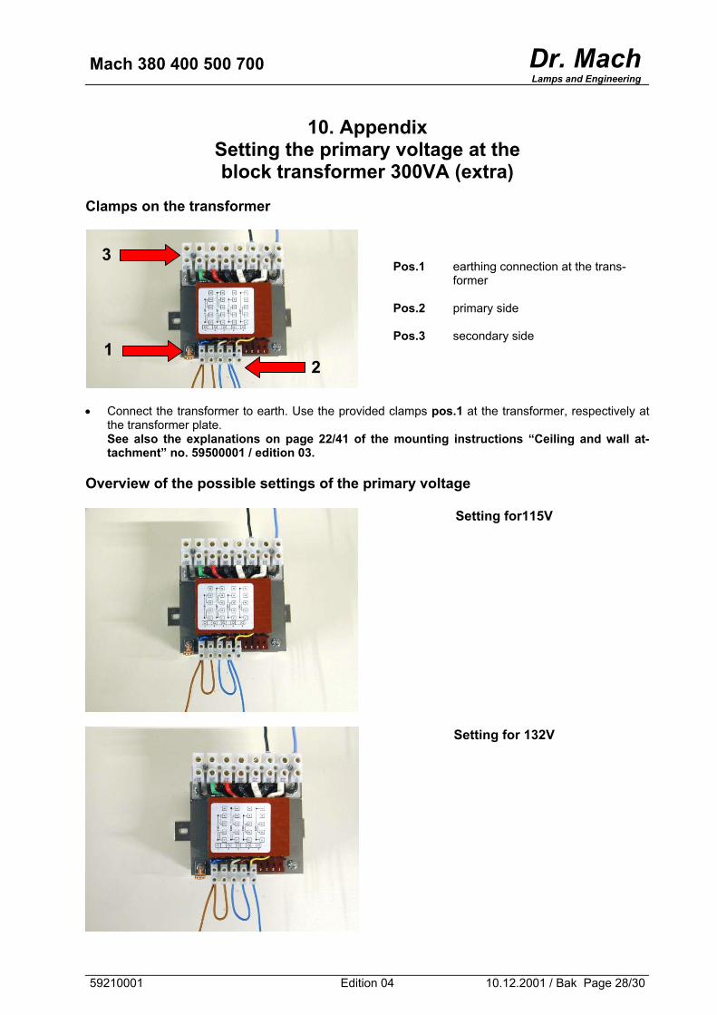
10. Appendix Setting the primary voltage at the block transformer 300VA (extra)
Clamps on the transformer
Pos.1 earthing connection at the trans-former
Pos.2 primary side Pos.3 secondary side
1
•
O
5
Connect the transformer to earth. Usthe transformer plate. See also the explanations on pagtachment” no. 59500001 / edition 0
verview of the possible setting
9210001
2
3
e the provided clamps pos.1 at the transformer, respectively at
e 22/41 of the mounting instructions “Ceiling and wall at-3.
s of the primary voltage
Setting for115V
Setting for 132V
Edition 04 10.12.2001 / Bak Page 28/30

Mach 380 400 500 700 Dr. MachLamps and Engineering
Setting for 230V
Setting for 247V
59210001 Edition 04 10.12.2001 / Bak Page 29/30
Mach 380 400 500 700 Dr. MachLamps and Engineering
59210001 Edition 04 10.12.2001 / Bak Page 30/30
![Mach number P w,test [bar] P model [bar] 1.8 -0.45 -0.20 0 ...ae342/18/lab2/lab2data.pdf · Mach 2.0 Snapshot . Mach 1.8 Snapshot . Mach 2.3 Snapshot Mach 2.2 Snapshot . P w,test](https://img.dokumen.tips/doc/110x75/5fb4e5220b26be1bae0aea08/mach-number-p-wtest-bar-p-model-bar-18-045-020-0-ae34218lab2-.jpg)