Embed Size (px)
Citation preview
International Journal of Scientific & Engineering Research Volume 2, Issue 10, Oct-2011 1 ISSN 2229-5518
IJSER © 2011 http://www.ijser.org
M-CMTS & DOCSIS 3.0 Standards at High Speed
Sadhana Pal, Gyan Prakash, Aradhana Jyotsana, Vivek Birla
Abstract: There are many challenges to cable operators. The main challenge that operators face to provide a Connected Life experience is lack of available bandwidth. Operators need to deliver more downstream and upstream band width to provide a fat pipe to and from the home. DOCSIS 3.0 is one of the best solutions to deliver higher band width. DOCSIS 3.0 addresses the bandwidth crunch in both the upstream and downstream directions. Another challenge is to deliver Higher Bandwidth at a Reduced Cost per Bit. While the need for bandwidth is enormous, operators have to be able to deliver next generation, high-bandwidth services at a reduced cost in order to stay competitive in the marketplace. The modular M-CMTS and I-CMTS solutions provide the building blocks to enable operators to offer highly competitive, high-bandwidth services at a reduced cost per bit. By using M-CMTS and deploying U-EQAM modulators, operators now can easily migrate to a high-bandwidth service to the home and enjoy greatly reduced capital expenditures (CapEx). Keywords: DOCSIS 3.0, M-CMTS, Speed, Bandwidth
—————————— —————————— Introduction: DOCSIS 3.0 is series of specifications that define the third generation of high speed data over cable systems. DOCSIS 3.0 provides a number of enhancements to the existing DOCSIS standard, most notably, channel bonding, support for IPv6, and support for IPTV. Channel bonding provides cable operators with a flexible way to significantly increase downstream speeds to a minimum of 160 Mbps, and upstream throughput up to a minimum rate of 120 Mbps to customers. DOCSIS3.0 addresses the following service goals-increasing channel capacity, enhancing the network security, expanding addressability of network elements and deploying new service offerings. MSOs can leverage existing M-CMTS architecture to allow them to meet customer demands for higher bandwidth with DOCSIS3.0 edge-QAMs and channel bonding features. This architecture separates the downstream physical layer processing from the core CMTS and moves it to Harmonic's NSG 9000 universal edge- QAM, improving downstream data rates and significantly reducing costs. The NSG 9000 supports both wideband M-CMTS and M-CMTS solutions delivered using existing cable modems. The NSGs are already deployed in over 10 M-CMTS systems around the world including North America, Asia and Europe. M-CMTS architecture: The M-CMTS architecture includes a DOCSIS Timing server to maintain a consistent timing reference
between the M-CMTS core and EQAM, as well as to mitigate the propagation delay differences of these two components. The DOCSIS Timing Interface (DTI) runs between the DTI Server and the M-CMTS and EQAM devices. The M-CMTS architecture was created to accomplish the following:
Allow operators to deploy independently scalable numbers of downstream DOCSIS channels without changing the MAC (media access control) domain or the number of upstream DOCSIS channels.
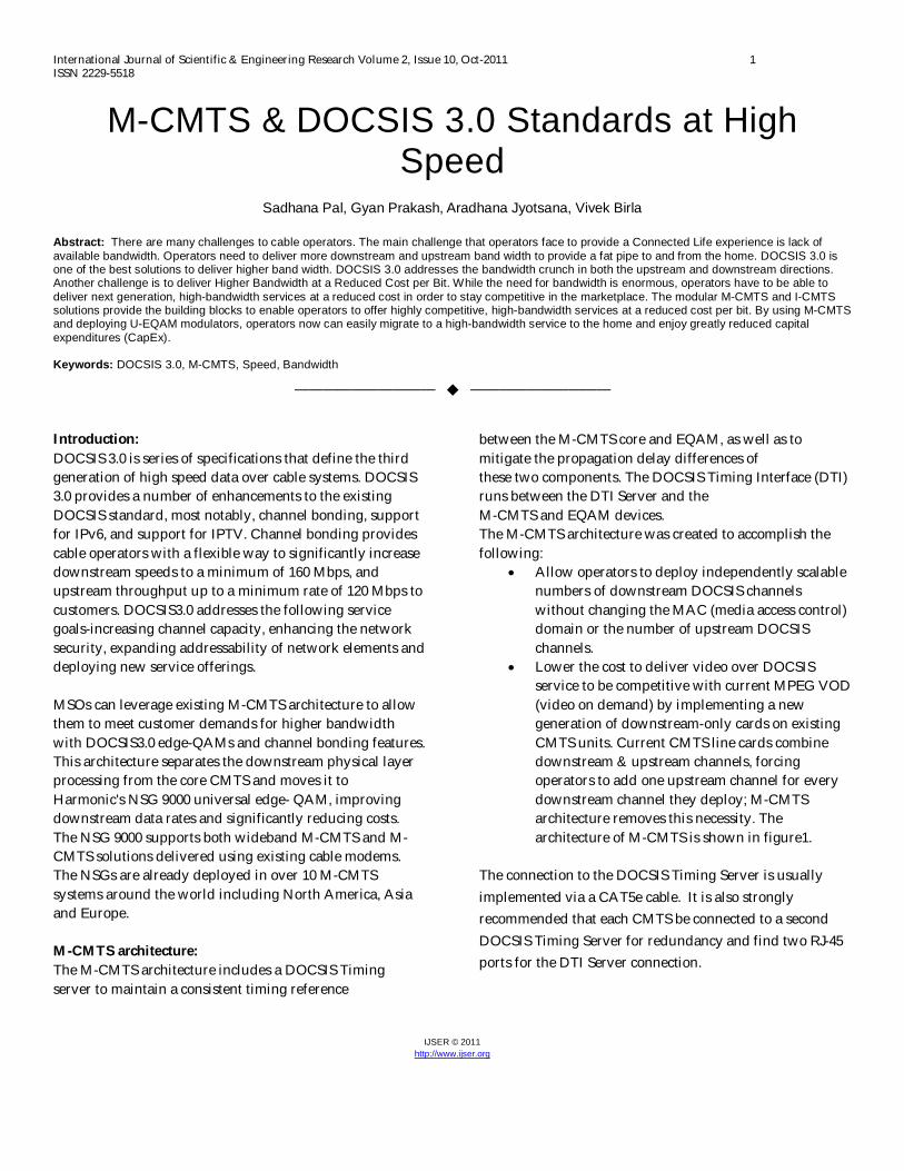
Lower the cost to deliver video over DOCSIS service to be competitive with current MPEG VOD (video on demand) by implementing a new generation of downstream-only cards on existing CMTS units. Current CMTS line cards combine downstream & upstream channels, forcing operators to add one upstream channel for every downstream channel they deploy; M-CMTS architecture removes this necessity. The architecture of M-CMTS is shown in figure1.
The connection to the DOCSIS Timing Server is usually implemented via a CAT5e cable. It is also strongly recommended that each CMTS be connected to a second DOCSIS Timing Server for redundancy and find two RJ-45 ports for the DTI Server connection.
International Journal of Scientific & Engineering Research Volume 2, Issue 10, Oct-2011 2 ISSN 2229-5518
IJSER © 2011 http://www.ijser.org
Figure 1. Architecture of M-CMTS DOCSIS 3.0 specialized interface card for communicating between the M-CMTS core and EQAM. This card will typically have a GBIC interface so that it can be configured with either copper or (CAT5e) or optical (multi-mode fiber) between the CMTS chassis and the EQAM. There are multiple ports because CMTS will likely be transferring more traffic in the downstream than one gigabit Ethernet port can handle. From a configuration standpoint, once the wideband interface card is added, all of the DOCSIS 3.0 downstream channels bonding commands are enabled in the DOCSIS 3.0 IOS that is installed in the system. It is at this point that configuration of the downstream bonding groups to their respective MAC address in the EQAM occur. Once properly configured, the CMTS core will be bound to the EQAM over the physical connection between the wideband card and EQAM. Downstream data is transmitted over the primary (CMTS) downstream channel and over the bonded EQAM channels as defined in the CMTS running configuration. The link between the CMTS wideband card and the EQAM uses a DOCSIS 3.0 protocol called Downstream External-Phy Interface (DEPI). DEPI is based upon the L2TPv3 protocol, which in layman’s terms is a very good protocol for transmitting multiple streams of IP data over the same physical media. The reason this is important in the DOCSIS 3.0 network is because the DEPI must be able to manage not just data, but also video while managing QoS.
In the future, when a significant portion of DOCSIS downstream throughput becomes IPTV and data rate requirements grow beyond what can be met by an integrated CMTS; M-CMTS architecture could provide the flexibility to meet growing throughput demands. M-CMTS Components:
EQAM (Edge QAM Device): System with multiple Gigabit Ethernet interfaces on the input side and multiple QAM modulators and up-converters on the output side.
M-CMTS Core: Contains the DS MAC and all the initialization & operational DOCSIS related software. In the future US receivers may be external to the M-CMTS core.
DTI (DOCSIS Timing interface) Server: provides a common frequency of 10.24 MHz and a DOCSIS time stamp to M-CMTS elements.
DEPI (Downstream External-Physical Interface): DEPI is an IP Tunnel that exist in the downstream direction between the DOCSIS MAC in the M-CMTS Core and the DOCSIS PHY that exists in the EQAM.
Edge Resource Manager (ERM): Manages the dynamic assignment of QAM channel resources to CMTS MAC domains.
Upstream & Downstream: The CMTS MAC domain typically includes one or more downstream paths and one or more upstream paths. Depending on the CMTS configuration, the CMTS MAC domain can be defined to have its downstream on one cable interface line card with its up-streams on another card, or one or more CMTS MAC domains per cable interface line card. The upstream channel is characterized by many CMs (or CMs in STBs) transmitting to the CMTS. These signals typically operate in a burst mode of transmission. Time in the upstream channel is slotted. The CMTS provides time slots and controls the usage for each upstream interval. The CMTS sends regular mappings of mini-slot structure in downstream broadcast MAP messages. The CMTS allocates contention broadcast slots that all CMs can use, and allocates upstream mini-slots for unicast or non-contention data from specific CMs.
International Journal of Scientific & Engineering Research Volume 2, Issue 10, Oct-2011 3 ISSN 2229-5518
IJSER © 2011 http://www.ijser.org
The CMTS allocates two basic types of contention slots on the upstream:
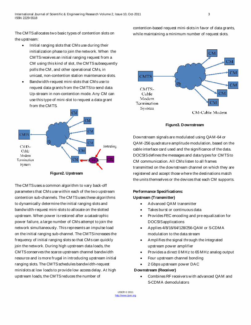
Initial ranging slots that CMs use during their initialization phase to join the network. When the CMTS receives an initial ranging request from a CM using this kind of slot, the CMTS subsequently polls the CM, and other operational CMs, in unicast, non-contention station maintenance slots.
Bandwidth-request mini-slots that CMs use to request data grants from the CMTS to send data Up-stream in non-contention mode. Any CM can use this type of mini-slot to request a data grant from the CMTS.
Figure2. Upstream
The CMTS uses a common algorithm to vary back-off parameters that CMs use within each of the two upstream contention sub-channels. The CMTS uses these algorithms to dynamically determine the initial ranging slots and bandwidth-request mini-slots to allocate on the slotted upstream. When power is restored after a catastrophic power failure, a large number of CMs attempt to join the network simultaneously. This represents an impulse load on the initial ranging sub-channel. The CMTS increases the frequency of initial ranging slots so that CMs can quickly join the network. During high upstream data loads, the CMTS conserves the scarce upstream channel bandwidth resource and is more frugal in introducing upstream initial ranging slots. The CMTS schedules bandwidth-request minislots at low loads to provide low access delay. At high upstream loads, the CMTS reduces the number of
contention-based request mini-slots in favor of data grants, while maintaining a minimum number of request slots.
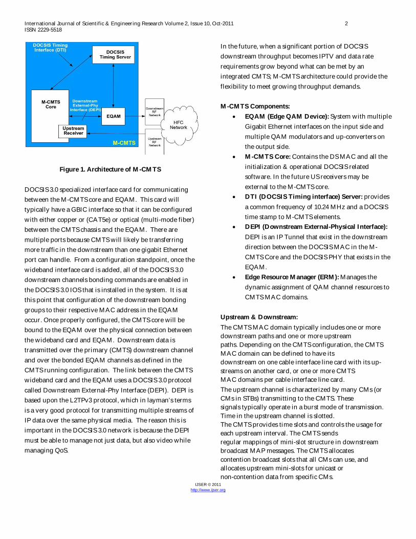
Figure3. Downstream
Downstream signals are modulated using QAM-64 or QAM-256 quadrature amplitude modulation, based on the cable interface card used and the significance of the data. DOCSIS defines the messages and data types for CMTS to CM communication. All CMs listen to all frames transmitted on the downstream channel on which they are registered and accept those where the destinations match the units themselves or the devices that each CM supports. Performance Specifications: Upstream (Transmitter)
Advanced QAM transmitter Takes burst or continuous data Provides FEC encoding and pre equalization for
DOCSIS applications Applies 4/8/16/64/128/256-QAM or S-CDMA
modulation to the data stream Amplifies the signal through the integrated
upstream power amplifier Provides a direct 0 MHz to 65 MHz analog output Four upstream channel bonding 2 Gbps upstream power DAC
Downstream (Receiver) Combines RF receivers with advanced QAM and
S-CDMA demodulators
International Journal of Scientific & Engineering Research Volume 2, Issue 10, Oct-2011 4 ISSN 2229-5518
IJSER © 2011 http://www.ijser.org
Can bond up to 8 downstream channels Receivers support 4/16/32/64/128/25 6/512/1024
QAM FEC decoding Delivers final data stream in a serial MPEG-2
transport format All gain clock and tracking loops are integrated in
the QAM receiver.
Speed: General speed:
• Speed can be split up in downstream speed (DS) and upstream speed (US)
• In US as well as in DS each one channel at a time (if capacity is too low, 2nd channel cannot be added)
• If n is number of allowed US channels per DS channel then the asymmetry is given by DS : (n x US) e.g.: DS = 38 Mb/s, US = 2.5 Mb/s n = 4 the asymmetry is 38 : (4 x 2.5) = 3.8 (or 3.8 : 1)
Speed/Bandwidth: Choice of speed/bandwidth ratios:
• DS: 64QAM, (128QAM) and 256QAM PAL oriented network accepts 64QAM only - network CNR is too low for 256QAM - CNR increase is very expensive
• US: QPSK and 16QAM 16QAM in speed, two times as efficient as QPSK but: - network less reliable for 16QAM - number of CM's/CMTS reduced by 50%
Speed Downstream: • 64QAM gives 6 b/s/Hz (ref. 64 = 26) so in theory:
8 MHz channel gives 8 x 6 = 48 Mb/s • Due to filtering, FEC etc. result: 38 Mb/s
effective bit-rate lower (between 20-25%), before IP handling service independent
• UDP/IP consumes approx. 1% (streaming, telephony) result: 37 Mb/s
• TCP/IP consumes another 10% (web-serving, E-mail) result: 34 Mb/s
Speed Upstream: • QPSK gives 2 b/s/Hz (ref. 4 = 22)
so in theory: 1.7 MHz channel gives 1.7x2 = 3.4 Mb/s
• Due to filtering, FEC etc. result: 2.56 Mb/s effective bit-rate is lower (approx. 35%), before IP handling service independent
• UDP/IP consumes approx. 5% (due to asymmetry) (streaming, telephony) result: 2.5 Mb/s
• TCP/IP consumes another 40% (due to asymmetry) (web serving, E-mail) result: 1.5 Mb/s
Modems per CMTS on service level • Let say QoS = DS 256kb/s /US 64kb/s TCP
DS: 1 TX = 34 Mb/s 34 : 0.256 = 136 users US: 4 RX = 4x1.5 Mb/s 6 : 0.064 = 100 users For Web surfing for a concurrency of 1%, 10 000 users could be connected to one CMTS 1 TX - RX combination
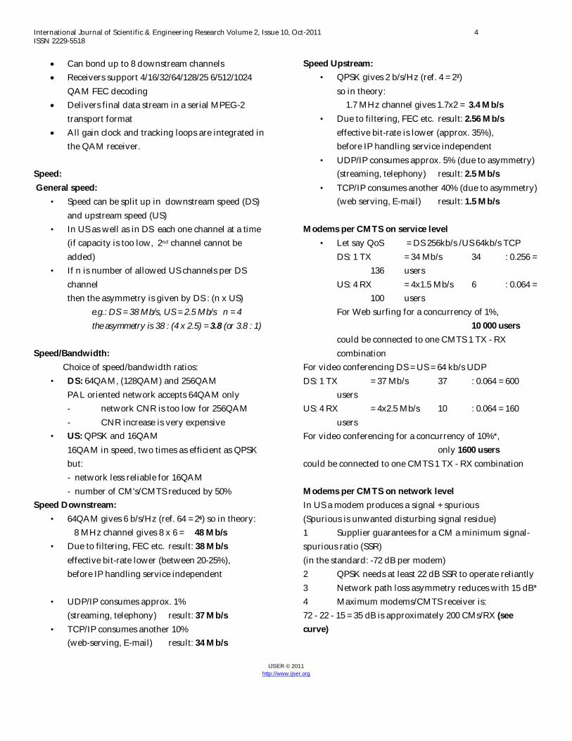
For video conferencing DS = US = 64 kb/s UDP DS: 1 TX = 37 Mb/s 37 : 0.064 = 600 users US: 4 RX = 4x2.5 Mb/s 10 : 0.064 = 160 users For video conferencing for a concurrency of 10%*, only 1600 users could be connected to one CMTS 1 TX - RX combination Modems per CMTS on network level In US a modem produces a signal + spurious (Spurious is unwanted disturbing signal residue) 1 Supplier guarantees for a CM a minimum signal-spurious ratio (SSR) (in the standard: -72 dB per modem) 2 QPSK needs at least 22 dB SSR to operate reliantly 3 Network path loss asymmetry reduces with 15 dB* 4 Maximum modems/CMTS receiver is: 72 - 22 - 15 = 35 dB is approximately 200 CMs/RX (see curve)
International Journal of Scientific & Engineering Research Volume 2, Issue 10, Oct-2011 5 ISSN 2229-5518
IJSER © 2011 http://www.ijser.org
Asymmetry reduction helps: 72 - 22 - 9 = 41 dB is approx. 500 CMs/RX 5 Each doubling of modems reduces SSR with 4.5 dB So, for e.g. 256 modems (is 28) reduction is 8 x 4.5 = 36 dB
Figure4. Graph between modem quantity vs dB
CMTS Comparison Physical 7ft / 19’’ rack mounted
• CMTS1: – 12 slots for RF line cards and network side
interfaces – 1x4 RF line card with 1 downstream and 4
upstream – Total port capacity per rack: 36 DS &
144 US* – Roadmap:2x8 and 3x12 RF line cards
• CMTS2: – 4 slots for RF line cards and 2 slots for
network side interfaces – 1x6 RF line card with 1 downstream and 6
upstream – Total port capacity per rack: 16 DS &
96 US* – Roadmap:2x8 RF line cards (5x20 for
bigger chassis) • CMTS3:
– 14 slots for RF line cards and network side interfaces
– 1x4 RF line card with 1 downstream and 4 upstream
– Total port capacity per rack: 42 DS & 168 US*
– Roadmap:2x8 and 4x32 RF line cards
CMTS Comparison Data throughput • CMTS1:
– Downstream, 8 MHz, 64QAM: max. 38 Mbps (measured)
– Upstream, 1.6 MHz, QPSK: max. 1.3 Mbps (measured)
– Forwarding capacity: 30 Mbps (theoretical)
• CMTS2: – Downstream, 8 MHz, 64QAM: max. 38
Mbps (measured) – Upstream, 1.6 MHz, QPSK: max. 1.7
Mbps (measured) – Forwarding capacity: 24 Mbps
(theoretical) • CMTS3:
– Downstream, 8 MHz, 64QAM: (measured at FTC’s lab)
– Upstream, 1.6 MHz, QPSK: (measured at FTC’s lab)
– Forwarding capacity: 42 Mbps (theoretical)
CMTS Comparison: Network Side Interfaces
• CMTS1: – Octal 10/100BaseT, GbEth, POS STM-1/4
• CMTS2: – Single 10/100BaseT, GbEth, POS STM-1/4,
ATM OC-3 • CMTS3:
– Octal 10/100BaseT, GbEth, POS STM-1/4
Conclusion: DOCSIS 3.0 offers new enhancements to the
multicasting capabilities available in previous DOCSIS versions. These enhancements allow DOCSIS 3.0 to more efficiently allocate network bandwidth to multiple users, freeing up network capacity for other revenue generating services.
Provides operators with the ability to increase downstream capacity to the existing customer base of DOCSIS 1.x/2.0 subscribers at a fraction of the cost of a traditional downstream channel.
International Journal of Scientific & Engineering Research Volume 2, Issue 10, Oct-2011 6 ISSN 2229-5518
IJSER © 2011 http://www.ijser.org
Capable of downloading up to 2000 times faster than 56k analog phone modems; up to 4 times faster than DOCSIS 2.0 broadband.
Greatly minimizes operator’s DOCSIS 3.0 time to market and deployment risk.
Designed to provide a cost effective, next generation technology to offer a high speed residential or commercial service tier
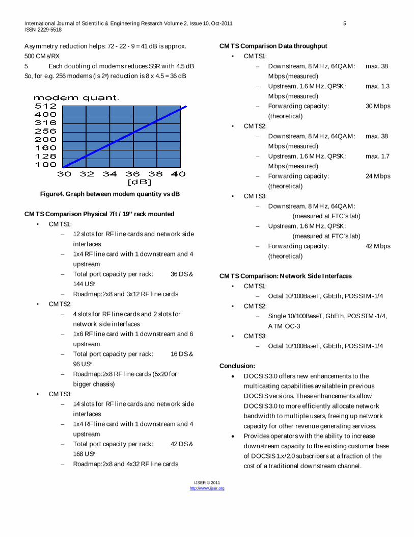
Future Roadmap: DOCSIS 3.0 Future Roadmap provides the mechanism to continually increase the downstream capacity of the CMTS. Figure.5 shows how DOCSIS 3.0 solution increases the CMTS capacity by more than 120 percent while reducing the cost of a downstream port by 85 percent.
Figure5. CMTS Cost and Density Curve DOCSIS 3.0 & M-CMTS deliver highest capacity with lowest possible price point, exceeding its initial goal of gaining 10 times the bandwidth at one-tenth of the cost. References: [1] Charles, A., Eldering, Nageen Himayet and Floyd, M., Gardner, “CATV Return Path Characterization for Reliable Communications,” IEEE Communications Magazine (1995). [2] Cable Television Laboratories, Inc., Data-Over-Cable Service Interface Specifications DOCSIS 2.0, Radio Frequency Interface Specification, SP-RFIv2.0-I09- 050812 (2005). [3] Cable Television Laboratories, Inc., Data-Over-Cable Service Interface Specifications DOCSIS 1.1, Radio
Frequency Interface Specification, SP-RFIv1.1-I09-020830 (2002). [4] Rouzbeh, Y., “DOCSIS overview for DOCSIS Community Q3 2001,” http://www.cablemodem.com (2001). [5] Schwartz, M., “For More DOCSIS/2.0 Modems Gain CableLabs/Certified/Status,” http://www.cablelabs.com/news/ (2003). [6] Lin, Y. D., Yin, W. M. and Huang, C. Y., “An Investigation Into HFC MAC Protocols: Mechanisms, Implementation, and Research Issues,” IEEE Communication Surveys, http://www.comsoc.org/pubs/surveys, Third Quarter (2000). [7] Lakshman, T. V., Madhow, U. and Suter, B., “Window- based Error Recovery and Flow Control with a Slow Acknowledgement Channel: A Study of TCP/IP Performance,” Proceedings of Infocom ’97 (1997). [8] Lin, Y. D., Huang, C. Y. and Yin, W. M., “Allocation and Scheduling Algorithm for IEEE 802.14 and MCNS in Hybrid Fiber Coaxial Networks,” IEEE Trans. Broadcasting, Vol. 44, p. 42735 (1998). [9] Cisco network [10] Donaldson, G. and Jones, D., “Cable Television Broadband Network Architectures,” IEEE Communications Magazine, pp. 122_126 (2001).