Embed Size (px)
Citation preview

M-Class Operator’s Manual
Copyright Information:
CG Triumvirate is a trademark of Agfa Corporation. CG Times based upon Times New Roman under license from the Monotype Corporation. Windows is a registered trademark of the Microsoft Corporation. All other brand and product names are trademarks, service marks, registered trademarks, or registered service marks of their respective companies.
Firmware (Software) Agreement
The enclosed Firmware (Software) resident in the Printer is owned by Licensor or its suppliers and is licensed for used only on a single printer in the user’s Trade or Business. The User agrees not to, and not to authorize or permit any other person or party to, duplicate or copy the Firmware or the information contained in the non-volatile or programmable memory. The firmware (Software) is protected by applicable copyright laws and Licensor retains all rights not expressly granted. In no event will Licensor or its suppliers be liable for any damages or loss, including direct, incidental, economic, special, or consequential damages, arising out of the use or inability to use the Firmware (Software). Information in this document is subject to change without notice and does not represent a commitment on the part of Datamax Barcode Products Corporation. No part of this manual may be reproduced or transmitted in any form or by any means, for any purpose other than the purchaser's personal use, without the expressed written permission of Datamax Corporation.
All rights reserved. Printed in the United States of America.
© Copyright 2005 by Datamax Corporation
Part Number: 88-2313-01
Revision: E

Agency Compliance and Approvals:
C US Listed
UL60950 Information Technology Equipment C22.2 No. 950-M93
EN60950
For 230 Volt Operation (Europe): Use a cord set, marked "HAR," consisting of a min H05VV-F cord which has a minimum 0.75 square mm diameter conductors, provided with an IEC 320 receptacle and a male plug for the country of installation rated 6A, 250V
Für 230 Volt (Europa): Benützen Sie ein Kabel, das mit "HAR" markiert ist, bestehend mindestens aus einem H05VV-F Kabel, das mindestens 0,75 Quadratmillimeter Drahtdurchmesser hat; sowie eine IEC320 Steckdose und einen für das Land geeigneten Stecker, 6A, 250 Volt.
As an Energy Star Partner, the manufacturer has determined that this product meets the Energy Star guidelines for energy efficiency.
The manufacturer declares under sole responsibility that this product conforms to the following standards or other normative documents:
EMC: EN 55022 (1993) Class B EN 50024 (1998)
Safety: This product complies with the requirements of EN 60950 /A11:1997
Gost-R
FCC: This device complies with FCC CFR 47 Part 15 Class A.
Note: This equipment has been tested and found to comply with the limits for a Class A digital device, pursuant to Part 15 of the FCC Rules. These limits are designed to provide reasonable protection against harmful interference when the equipment is operated in a commercial environment. This equipment generates, uses, and can radiate radio frequency energy, and if not installed and used in accordance with the instructions in this manual, it may cause harmful interference to radio communications. Operation of this equipment in a residential area is likely to cause harmful interference in which case the user will be required to correct the interference at his own expense.

Important Safety Instructions
This printer has been carefully designed to provide many years of safe, reliable performance. As with all types of electrical equipment, however, there are a few basic precautions you should take to avoid hurting yourself or damaging the device: • Carefully read the installation and operating instructions provided with your printer. • Read and follow all warning instruction labels on the printer. • Place the printer on a flat, firm, solid surface. • To protect your printer from overheating, make sure all openings on the printer are not blocked. • Do not place the printer on or near a heat source. • Do not use your printer near water, or spill liquid into it. • Be certain that your power source matches the rating listed on your printer. If you are unsure, check with your dealer
or with your local power company. • Do not place the power cord where it will be walked on. If the power cord becomes damaged or frayed replace it
immediately. • Do not insert anything into the ventilation slots or openings on the printer. • Only qualified, trained service technicians should attempt to repair your printer.

i
Printer Overview
1.0 Introduction................................................................... 1
1.1 About this Printer .......................................................... 2
1.1.1 Standard Features ............................................. 2
1.1.2 Optional Features............................................... 3
Getting Started 2.0 Before Using the Printer ............................................... 5
Setting Up the Printer 3.0 Introduction................................................................... 7
3.1 Connecting the Printer.................................................. 7
3.1.1 Power Connection.............................................. 7
3.1.2 Interface Connection .......................................... 8
3.2 Loading Media .............................................................. 9
3.3 Media Sensor Adjustment ............................................ 12
3.4 Loading Ribbon ............................................................ 13
3.4.1 Ribbon Routing .................................................. 15
Using the Front Panel (Non-display printers) 4.0 Introduction................................................................... 17
4.01 DMXConfig......................................................... 17
4.1 Lights ............................................................................ 18

ii
4.2 Buttons ......................................................................... 18
4.3 Normal Mode - Button Functions.................................. 19
4.4 Express Setup Mode - Button Functions ...................... 20
4.5 Printer Setup Mode - Button Functions ........................ 21
4.5.1 Printer Setup Menu List...................................... 22
4.5.2 Menu Items and Values ..................................... 23
4.5.3 Step by Step Modification of the Printer Setup .. 26
4.6 Label Alignment............................................................ 28
4.6.1 Label Alignment = YES ...................................... 28
4.6.2 Label Alignment = AUTO ................................... 29
4.6.3 Label Alignment = NO........................................ 29
4.6.4 Label Alignment Troubleshooting....................... 30
4.7 Calibration Mode – Button Functions ........................... 32
4.7.1 Auto Media Sensor Calibration .......................... 33
4.7.2 Manual Media Sensor Calibration ...................... 34
4.8 Internal Labels .............................................................. 35
4.8.1 Database Configuration and Test Labels........... 35
4.8.2 Test Label .......................................................... 37
Using the Front Panel (Display-equipped printers) 5.0 Introduction................................................................... 39
5.0.1 Ready Mode....................................................... 39

iii
5.0.2 Menu Mode ........................................................ 40
5.0.3 Quick Test Mode ................................................ 41
5.0.4 Indicator Lights................................................... 42
5.0.5 LCD .................................................................... 42
5.1 The Menu System ........................................................ 43
5.1.1 Entrance and Exit Prompts ................................ 43
5.1.2 Media Settings ................................................... 44
5.1.3 Print Control ....................................................... 46
5.1.4 Printer Options ................................................... 47
5.1.5 System Settings ................................................. 49
5.1.6 Communications ................................................ 56
5.1.7 Diagnostics......................................................... 60
5.1.8 MCL Options ...................................................... 61
5.2 Display Messages ........................................................ 62
5.2.1 User Prompts and Condition Messages............. 62
5.3 Quick Test Mode .......................................................... 64
5.3.1 Print Quality Label.............................................. 64
5.3.2 Configuration Label ............................................ 65
5.3.3 Quick Ribbon Test Label.................................... 66
5.3.4 Validation Label.................................................. 66
5.3.5 Print Last Label .................................................. 67
iv
5.3.6 User Defined Label ............................................ 67
5.4 Media Sensor Calibration ............................................. 68
5.4.1 Quick Calibration................................................ 68
5.4.2 Standard Calibration .......................................... 69
5.4.3 Advanced Entry Calibration................................ 72
Maintenance and Adjustments 6.0 Introduction................................................................... 79
6.1 Cleaning the Printhead................................................. 80
6.1.1 Automated Printhead Cleaning .......................... 81
6.2 Media Width Adjustment............................................... 82
6.3 Printhead Burn Line Adjustment................................... 83
6.4 Printhead Pressure Adjustment.................................... 84
6.5 Printhead Replacement ................................................ 85
6.6 Darkness Adjustment ................................................... 86
6.7 Resetting the Printer..................................................... 86
6.8 Downloading Firmware and Fonts................................ 88
Troubleshooting 7.0 Problem Resolution ...................................................... 89
7.1 Fault and Warning Messages....................................... 93
7.2 Hex Dump Mode........................................................... 98
Specifications ............................................................... 99

v
Appendix A
ASCII Control Code Chart.................................................... 103
Appendix B Embedded Fonts and Barcodes .......................................... 105
Appendix C Optional Internal Ethernet Printer Server............................. 115
Appendix D Menu System Multi-Language Support................................ 141
Advanced File Handling Information.................................... 145
Appendix E Saving a Configuration File.................................................. 147
Appendix F GPIO Port Description ......................................................... 149
Warranty ............................................................................ 153
Glossary ............................................................................ 155

vi
M-Class 1
1.0 Introduction
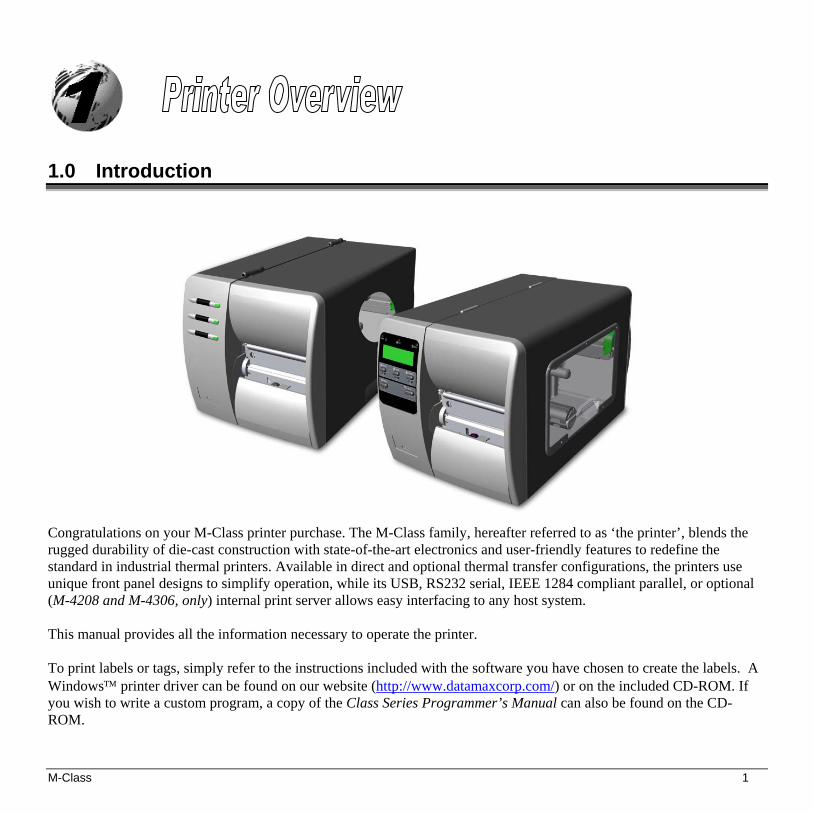
Congratulations on your M-Class printer purchase. The M-Class family, hereafter referred to as ‘the printer’, blends the rugged durability of die-cast construction with state-of-the-art electronics and user-friendly features to redefine the standard in industrial thermal printers. Available in direct and optional thermal transfer configurations, the printers use unique front panel designs to simplify operation, while its USB, RS232 serial, IEEE 1284 compliant parallel, or optional (M-4208 and M-4306, only) internal print server allows easy interfacing to any host system.
This manual provides all the information necessary to operate the printer. To print labels or tags, simply refer to the instructions included with the software you have chosen to create the labels. A Windows™ printer driver can be found on our website (http://www.datamaxcorp.com/) or on the included CD-ROM. If you wish to write a custom program, a copy of the Class Series Programmer’s Manual can also be found on the CD-ROM.

2 M-Class
1.1 About this Printer This printer offers the following standard and optional features:
1.1.1 Standard Features Printing
Direct Thermal Printing
On Demand and Batch Printing
203 DPI (M-4206 and M-4208) 300 DPI (M-4306) Printhead
Date and Time Stamp
AGFA Scalable Font Engine
2 Resident Scaleable fonts, CG Triumvirate™ regular and bold-condensed (M-4208 and M-4306 only)
Memory
2 MB FLASH Memory (256K available to user, designated as Module B)
4 MB DRAM Memory (M-4206)
8 MB DRAM Memory (M-4208 and M-4306))
Interfaces
USB interface
DB-9 RS-232 serial interface
IEEE 1284 Centronics® parallel interface
Operational
Simple Media Loading
Media Tearbar
Fan-fold media compatible from the bottom and rear of printer

M-Class 3
1.1.2 Optional Features Thermal Transfer
A printing method that uses ribbon to produce exceptional image clarity (as compared to most direct thermal stocks). Note that this option must be specified for use with either ‘coated side in’ or ‘coated side out’ ribbon.
Media Cutter
A rotary-type mechanism to automatically cut material with a maximum thickness of .010” (.254 mm) into minimum lengths of 1.0 inches (25.4 mm). Designed for ease of operation, the Media Cutter is automatically detected, configured, and enabled when installed on the printer.
Peel and Present Mechanism (also requires the Internal Rewind option)
An output control device that automatically separates printed labels from the backing material and allows subsequent printing to occur only after the removal of a previously printed label. Minimum label length is 0.75 inches (19 mm). Designed for ease of operation, the Peel and Present Mechanism is automatically detected, configured, and enabled when installed on the printer.
Internal Rewind
An internal mechanism capable of winding printed labels or the label backing material only (when using the Peel and Present option) into a maximum four-inch outer diameter roll.
Present Sensor
An output control device that allows subsequent printing to occur only after the removal of a previously printed label. Designed for ease of operation, the Present Sensor is automatically detected, configured, and enabled when installed on the printer.
FLASH Memory Expansion
An optional Main Circuit Card Assembly available with 4MB (M-4206) or 8MB (M-4208 and M-4306) of Flash memory for International Language Printing Capability (ILPC) and/or additional fonts and graphics.
ILPC
A font set that allows International Language Print Capability consisting of one of the following:
CG-Times (western European) Scalable font
Kanji Gothic B Scalable font
Simplified Chinese GB Scalable font
Korean Hangul font

4 M-Class
External Ethernet Connectivity (uses printer’s parallel port)
A print server (the DMX100) that is an external Network Interface Controller (NIC) to provide Ethernet® connectivity.
Internal Ethernet Connectivity (printers equipped with a front display, only)
An internal Network Interface Controller (NIC) that enables the printer to provide Ethernet® connectivity. Features include:
Automatic selection of 10BaseT (Thinnet) or 100BaseT Fast Ethernet connection. Integral HTTP Server to allow monitoring and management from a standard Web browser program. FTP printing to allow printing directly from a Web browser or other FTP client. LPR/LPD over TCP/IP for UNIX platforms and Microsoft’s Windows. Raw sockets support over selectable TCP/IP port with filters for selected UNIX environment. IP SNMP support of MIB-2, proprietary NIC MIB and public and proprietary (private) Printer MIB. SNMP traps to alert administrators of printer errors (paper/ribbon out, head up, etc). DHCP, BootP, and RARP services supported
MCL (printers equipped with a front display, only)
A software tool suite designed for data collection applications. Once enabled, the printer can accept input data from peripheral devices such as barcode scanners, weigh scales, and keyboards without the need of a host computer, requesting and sending data to locally resident lookup files or remote databases, enhancing communication capabilities within your system while reducing your hardware investment.

M-Class 5
2.0 Before Using the Printer
Removing the Packaging
Inspect the shipping container(s) for damage. If damage is evident, immediately notify the shipping company to report the nature and extent of the damage.
The printer is carefully packaged to avoid any damage during transit. In order to operate the printer, you will need to remove the packaging materials (for example, the tape and foam) that were placed in the printer for shipment. Complete the following steps prior to connecting power or attempting to load media.
Ensure that the arrow on the box is pointing up, and then open the box.
Remove the top piece of packing foam. Lift the printer from the box. Remove the printer from the plastic bag.
Remove any tape or additional packing foam from the inside of the printer.
Note: It is a good idea to save all packaging materials in the event that shipping the printer is ever required.

6 M-Class
Inspecting the Printer After removing the printer from the packaging material, check the contents. The following items should be included: Printer
Power Cord
CD-ROM and Documentation
Any special or additionally purchased items.
Additional Requirements The following items are necessary for generating labels from your printer. Contact your customer support or sales representative for advice on which media and software may best be suited for your application. Serial, USB or Parallel cable
Ethernet cable for optional LAN connectivity
Applicable Media
Applicable Software
M-Class 7
3.0 Introduction
This Section explains how to connect your printer, load media (and ribbon, if equipped for thermal transfer).
3.1 Connecting the Printer
3.1.1 Power Connection
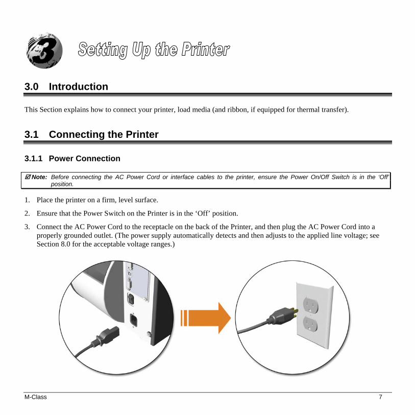
Note: Before connecting the AC Power Cord or interface cables to the printer, ensure the Power On/Off Switch is in the ‘Off’ position.
1. Place the printer on a firm, level surface.
2. Ensure that the Power Switch on the Printer is in the ‘Off’ position.
3. Connect the AC Power Cord to the receptacle on the back of the Printer, and then plug the AC Power Cord into a properly grounded outlet. (The power supply automatically detects and then adjusts to the applied line voltage; see Section 8.0 for the acceptable voltage ranges.)

8 M-Class
3.1.2 Interface Connection
The printer can be connected to the host via the parallel, USB, serial, or optional network interface. The printer will automatically connect to the first port that delivers valid data. Once established, the printer’s power must be cycled ‘Off’ and ‘On’ to change an interface connection. The Parallel Connection needs a Centronics® IEEE 1284 cable with a
36-pin male connector for unidirectional (forward channel) communications, or an IEEE 1284 Compliant cable for bi-directional communications (forward and reverse channels). Also, for bi-directional communications your host must have supporting software. See Section 5 for more information.
The USB Connection needs a USB cable and is supported in
Windows®95 and greater operating systems. Depending upon the operating system of your host computer, installation requirements may differ slightly.
The Serial Connection needs a serial interface cable with specific pin-
outs for proper communications (part numbers and pin-outs are given, below; contact your reseller to order). The interface supports RS-232C communications via a DB-9 connector. Serial port settings are menu-selectable and must match your host’s serial port settings; see Section 4, for non-display printers or Section 5 for display-equipped printers.
Part # 32-2300-01 Part # 32-2301-01
The Optional Internal Ethernet Print Server is available only for display-equipped printers. When using this
interface, refer to Appendix C, or the instructions included with the option for proper cabling, setup, and configuration.

M-Class 9
3.2 Loading Media
Load media into the printer as follows: 1. Open the media cover and lower the Media Hub Guide and Media Guide. 2. Press in on the Printhead Latch and raise the Printhead Assembly.

10 M-Class
3. Slide the Roll Media onto the Media Hub and raise the Media Hub Guide. The Media Hub Guide should be pushed inward so that it is just touching the Roll Media.
4. Route the Media through the printer as shown. Raise the Media Guide. The Media Guide should be pushed inward so
that it is just touching the edge of the Media.

M-Class 11
5. Close the Printhead Assembly and press down until it locks into place.
6. Close the cover and press the FEED button several times to position the media and ensure proper tracking.
If the printer does not correctly sense the top of each label, as denoted by the ERROR light, it may be necessary to:
Printers without front display: Perform the Auto Media Sensor Calibration, see section 4.7.1.
Printers with front display: Press and hold the FEED button until at least one label gap or mark is advanced then release. For additional calibration procedures, see section 5.4
Note: The printer is factory set to use 4-inch media (and ribbon, if thermal transfer equipped). When using a different width of
media/ribbon, please refer to section 6.2.
12 M-Class
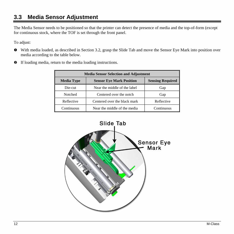
3.3 Media Sensor Adjustment
The Media Sensor needs to be positioned so that the printer can detect the presence of media and the top-of-form (except for continuous stock, where the TOF is set through the front panel. To adjust:
With media loaded, as described in Section 3.2, grasp the Slide Tab and move the Sensor Eye Mark into position over media according to the table below.
If loading media, return to the media loading instructions.
Media Sensor Selection and Adjustment
Media Type Sensor Eye Mark Position Sensing Required
Die-cut Near the middle of the label Gap
Notched Centered over the notch Gap
Reflective Centered over the black mark Reflective
Continuous Near the middle of the media Continuous
M-Class 13
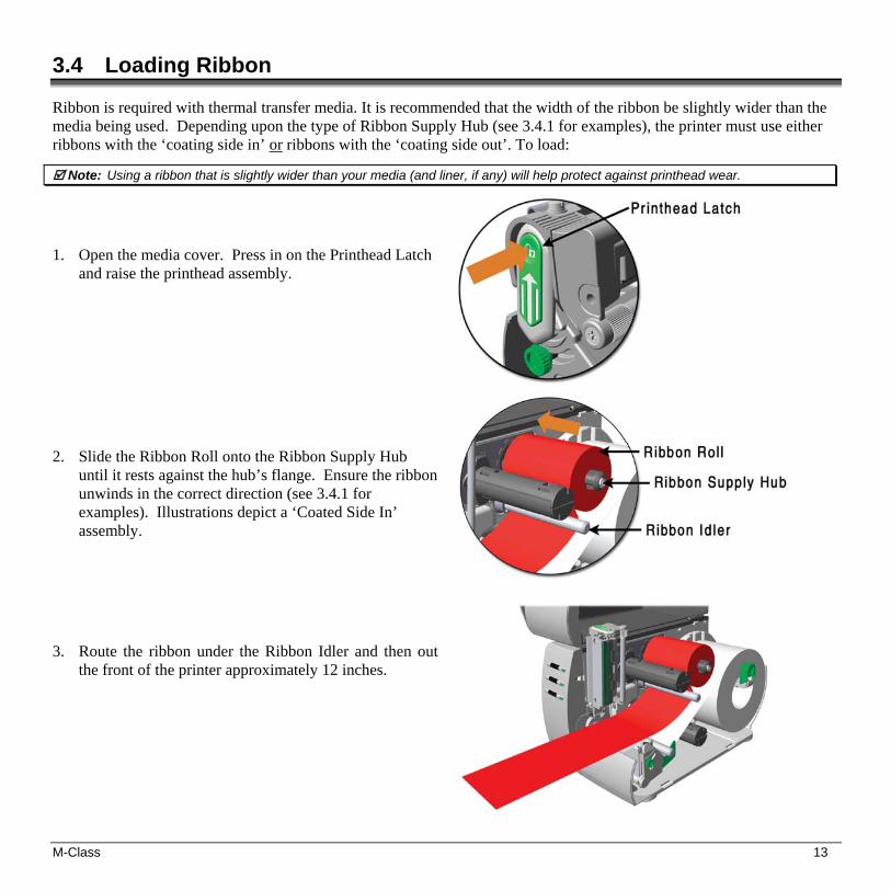
3.4 Loading Ribbon
Ribbon is required with thermal transfer media. It is recommended that the width of the ribbon be slightly wider than the media being used. Depending upon the type of Ribbon Supply Hub (see 3.4.1 for examples), the printer must use either ribbons with the ‘coating side in’ or ribbons with the ‘coating side out’. To load:
Note: Using a ribbon that is slightly wider than your media (and liner, if any) will help protect against printhead wear.
1. Open the media cover. Press in on the Printhead Latch
and raise the printhead assembly.
2. Slide the Ribbon Roll onto the Ribbon Supply Hub
until it rests against the hub’s flange. Ensure the ribbon unwinds in the correct direction (see 3.4.1 for examples). Illustrations depict a ‘Coated Side In’ assembly.
3. Route the ribbon under the Ribbon Idler and then out
the front of the printer approximately 12 inches.
14 M-Class
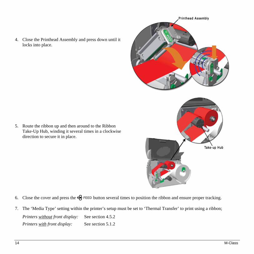
4. Close the Printhead Assembly and press down until it
locks into place.
5. Route the ribbon up and then around to the Ribbon
Take-Up Hub, winding it several times in a clockwise direction to secure it in place.
6. Close the cover and press the FEED button several times to position the ribbon and ensure proper tracking. 7. The ‘Media Type’ setting within the printer’s setup must be set to ‘Thermal Transfer’ to print using a ribbon;
Printers without front display: See section 4.5.2
Printers with front display: See section 5.1.2

M-Class 15
3.4.1 Ribbon Routing (Coated Side In & Coated Side Out)
Note: Directional Arrows near the Ribbon Supply Hub indicate the correct ribbon route. Ribbon types are available with the ink (coating) layer wound ‘in’ or ‘out’. These types are NOT interchangeable for use with the printer. Ensure the inked side of the ribbon faces the media and NOT the printhead.
Ribbon Routing Diagrams
‘Coating Side In’ Ribbon Supply Hub
‘Coating Side Out’ Ribbon Supply Hub

16 M-Class

M-Class 17
4.0 Introduction
The Front Panel consists of three indicator lights and three function buttons. The functions of these lights and controls are listed in the following sections.
4.01 DMXConfig DMXConfig (located on the M-class CD-ROM) is a Windows-based configuration utility that can simplify printer setup. This application allows the user to make changes to the existing printer setup without using the front panel buttons. Visit our website at www.datamaxcorp.com/software/m-class/ for the latest releases. DMXConfig Features: Simplify Printer Setup Process
Allows Real-Time Control/Query of Printer Configuration
Define and Save Optimal Configurations for Applications i.e. Ribbon / Label Stock Combinations
Saved Configurations can be Shared with other Printers and Sent via Email
Download Files, Formats and Fonts
Query Memory Modules
(Sample screenshot)
18 M-Class
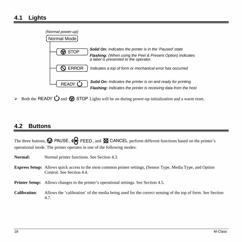
4.1 Lights
Normal Mode(Normal power-up)
STOPSolid On: Indicates the printer is in the ‘Paused’ stateFlashing: (When using the Peel & Present Option) Indicatesa label is presented to the operator.
Indicates a top of form or mechanical error has occurred
Solid On: Indicates the printer is on and ready for printingFlashing: Indicates the printer is receiving data from the host
ERROR
READY
Both the READY and STOP Lights will be on during power-up initialization and a warm reset.
4.2 Buttons The three buttons, PAUSE , FEED , and CANCEL perform different functions based on the printer’s operational mode. The printer operates in one of the following modes:
Normal: Normal printer functions. See Section 4.3. Express Setup: Allows quick access to the most common printer settings, (Sensor Type, Media Type, and Option
Control. See Section 4.4. Printer Setup: Allows changes to the printer’s operational settings. See Section 4.5. Calibration: Allows the ‘calibration’ of the media being used for the correct sensing of the top of form. See Section
4.7.

M-Class 19
4.3 Normal Mode - Button Functions In ‘Normal’ mode, the printer’s buttons control normal operations such as pause, feed, and cancel, as well as the test and reset functions by using button combinations as detailed below.
Pauses/Un-pauses the printer
Feeds one label. Clears fault conditions
Cancels the current batch of labels. Press the Pause button toprint the next batch of labels in the printer’s buffer
Normal Mode(Normal power-up)
CANCEL
PAUSE
FEEDPress and Hold to perform “Label Alignment”, see section 4.6
Button Combinations (push buttons simultaneously)
PAUSE +
FEED
Prints the Test Label, see Section 4.8.2.
PAUSE +
CANCEL
Performs a warm reset and returns to the Normal Mode of operation.
FEED
+
CANCEL
Produces Database Configuration and Test Labels, see Section 4.8.1

20 M-Class
4.4 Express Setup Mode - Button Functions The Express Setup is a unique printer feature that allows users quick access to the most commonly used printer settings. The selected setting is represent by a specific combination of the printer’s indicator lights for each of the three items, (Sensor Type, Media Type, and Option Control). To enter the Express Setup…
Turn the printer OFF to save settings.
M-Class 21
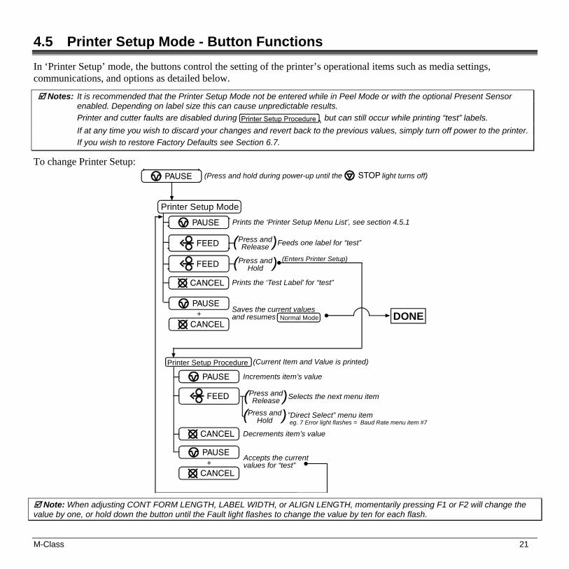
4.5 Printer Setup Mode - Button Functions
In ‘Printer Setup’ mode, the buttons control the setting of the printer’s operational items such as media settings, communications, and options as detailed below.
Notes: It is recommended that the Printer Setup Mode not be entered while in Peel Mode or with the optional Present Sensor enabled. Depending on label size this can cause unpredictable results.
Printer and cutter faults are disabled during , but can still occur while printing “test” labels.
If at any time you wish to discard your changes and revert back to the previous values, simply turn off power to the printer.
If you wish to restore Factory Defaults see Section 6.7.
To change Printer Setup:
Printer Setup Procedure
Printer Setup ModePrints the ‘Printer Setup Menu List’, see section 4.5.1
Prints the ‘Test Label’ for “test”
(Current Item and Value is printed)
Increments item’s value
Decrements item’s value
Accepts the currentvalues for “test”
PAUSE
PAUSE (Press and hold during power-up until the light turns off)STOP
PAUSE
Feeds one label for “test”Press andRelease( )FEED
FEED Press andHold( ) (Enters Printer Setup)
CANCEL
Saves the current valuesand resumes Normal Mode+
PAUSE
CANCEL
Press andRelease Selects the next menu item( )
Press andHold
”Direct Select” menu itemeg. 7 Error light flashes = Baud Rate menu item #7
( )FEED
CANCEL
+PAUSE
CANCEL
DONE
Note: When adjusting CONT FORM LENGTH, LABEL WIDTH, or ALIGN LENGTH, momentarily pressing F1 or F2 will change the value by one, or hold down the button until the Fault light flashes to change the value by ten for each flash.

22 M-Class
4.5.1 Printer Setup Menu List
The Printer Setup Menu List label, shown below, contains the printer’s current values for each menu item that can be modified via the front panel (See Section 4.5.2 for a detailed item description.) The Menu Item Numbers correspond to the item’s position in the Menu List for selection when pressing the FEED button during the Printer Setup Procedure (see Section 4.5). For example to “Direct Select” the BAUD RATE Menu Item press and hold the FEED button for 7 flashes of the ERROR light and then release or for the TOF GAIN item hold
FEED for 12 flashes, etc.
MenuItems
Values
1) DIRECT = MEDIA TYPE 2) EDGE = SENSOR TYPE 3) NO = PRESENT SENSOR 4) NO = CUTTER EQUIPPED 5) 127 = SOP ADJUST, 0.005 in. 6) 127 = PRESENT ADJUST, 0.005 in. 7) 9600 = BAUD RATE, bps 8) 8 = DATA BITS 9) STD = CONTROL CODES10) 100 = CONT FORM LENGTH, 0.01 in.11) 3 = OOS MAXVOLT, 0.1 Volts12) 12 = TOF GAIN13) 10 = TOF DELTA, 0.1 Volts14) 0 = TOF LOW, 0.1 Volts15) 426 = LABEL WIDTH, 0.01 in.16) 64 = SCALABLE FONT, 4KB17) 128 = INTERNAL MODULE, 4KB18) NO = LABEL ALIGNMENT19) 100 = ALIGNMENT LENGTH, 0.01 in.20) AUTO = OPTION CONTROL21) DPL = INPUT MODE22) STANDARD = DPL EMULATION23) 10 = HEAT24) NO = EXACT TIME25) NO = GPIO26) NO = NO REPRINT
Menu ItemNumbers
Note: When using narrow media, the ‘Menu Items’ column may be truncated.

M-Class 23
4.5.2 Menu Items and Values The table below details the Printer Setup Menu List items with a brief description of the item’s function, and the possible values. A “*” denotes the default setting.
1) MEDIA TYPE
Sets printing for direct thermal (no ribbon) or thermal transfer (ribbon) media.
Possible Values:
* DIRECT THERMAL THERMAL TRANSFER
2) SENSOR TYPE
Selects the sensor type used to detect the media’s Top Of Form (TOF) mark.
Possible Values:
* EDGE: gap / notch TOF marks REFL (Reflective): black marks CONT (Continuous): no TOF marks
3) PRESENT SENSOR
Enables/Disables the optional Present Sensor feature.
Possible Values:
* AUTO NO YES
4) CUTTER EQUIPPED
Enables/Disables the optional Media Cutter feature.
Possible Values:
* AUTO NO YES
5) SOP ADJUST
Sets the start of print (SOP) location, relative to the top of form.
Possible Values:
Range: 0 – 255; nominal = *128
(0 = close to edge; 255 = farthest from edge)
6) PRESENT ADJUST
Specifies an additional amount to feed the label after printing.
Possible Values:
Range: 0 – 255; nominal = *128
(0 = close to edge; 255 = farthest from edge)
7) BAUD RATE
Sets the serial port baud rate. (Must match the host setting).
Possible Values:
600 to 38.4k; default = *9600 BPS
8) DATA BITS
Sets the serial data word length (Must match the host setting).
Possible Values:
* 8 7
9) CONTROL CODES
Allows code selection listed in Programmer’s manual.
Possible Values:
* (STD) Standard Codes
(ALT) Alternate Codes
10) CONT FORM LENGTH
Sets the page (label) size when the ‘SENSOR TYPE’ is set to continuous media.
Possible Values:
Range: 0 – 9999; default = *100 (Units = .01 inch)
11) OOS MAXVOLT
Sets the media sensor level for the Out Of Stock condition.
Possible Values:
Range: 0 – 16; nominal = *2 (Units = .1 volt)
12) TOF GAIN
Sets media sensor Top of Form gain value.
Possible Values:
Range: 0 – 15; nominal = *10

24 M-Class
13) TOF DELTA
Sets the minimum media sensor change required to signify a label gap or mark.
Possible Values:
Range: 0 – 50; nominal = *10 (Units = .1 volt)
14) TOF LOW
Sets the minimum media sensor reading for paper (gap/notch) or mark (reflective).
Possible Values:
Range: 0 – 50; nominal = *0 (Units = 0.1 volt)
15) LABEL WIDTH
Sets the label width.
Possible Values:
Range: 75 – 426; default = *426 (Units = .01 inch)
16) SCALABLE FONT
Sets the number of memory blocks to allocate for scalable fonts.
Possible Values:
Range: 0 – 128; default = *64 (Units = 4K Bytes)
17) INTERNAL MODULE
Sets the number of memory blocks to allocate for the internal RAM module.
Possible Values:
Range: 0 – 128; default = *128 (Units = 4K Bytes)
18) LABEL ALIGNMENT
Sets the label alignment method (see Section 4.6).
Possible Values:
YES (user manually determines ‘ALIGN LENGTH’)
AUTO (printer determines ‘ALIGN LENGTH’)
* NO (no Label Alignment used)
19) ALIGN LENGTH
Leading edge distance of two successive labels. Must be entered if ‘LABEL ALIGNMENT’ is set to Yes (see Section 4.6).
Possible Values:
0 – 999; default =100* (Units = .01 inch)
20) OPTION CONTROL
Sets label stopping (and in certain cases the starting) location for different printer configurations.
Possible Values:
* AUTO (Automatically sets the stop location. Installed options will be ‘auto-sensed’ and the appropriate stop position will automatically be set. Host commands are ignored.)
HOST (Sets stop position according to options installed. If no options are installed the printer sets stop location to the next label’s start of print. Host commands will override.)

M-Class 25
21) INPUT MODE
Selects between the standard or template interpretation of incoming data.
Possible Values:
* DPL (printer constructs the label using the standard DPL commands)
LINE (printer constructs the label using a preloaded template form)
22) DPL EMULATION
This instructs the firmware to process specific DPL data (Start of Print, DPI, and Imaging function) according to the selected printer emulation.
Possible Values:
* STANDARD
ALLEGRO (Allegro Emulation)
P PLUS (Prodigy Plus Emulation)
PRODIGY (Prodigy Emulation)
23) HEAT
Controls the ‘burn-time’ of the printhead. This is the equivalent of Heat Setting on most label software programs.
Possible Values:
Range: 0 – 30; default = *10
24) EXACT TIME
Instructs the printer to wait until the system is idle before the next label’s data and time fields are formatted to eliminate any discrepancy between the buffered and printed times.
Possible Values:
YES or NO; default = *NO
25) GPIO
Sets the printer’s option port to function for GPIO applications, (see Appendix F for more information).
Possible Values:
YES or NO; default = *NO
26) NO REPRINT
When a fault condtions is detected, printing stops and the ERROR light turns on. After the problem is corrected, the FEED Key must be pressed to clear the fault. The label in process is not reprinted.
Possible Values:
YES or NO; default = *NO (NO = NO REPRINT” disabled, reprinting will occur.)
Note: All of the values for these Menu Items will be stored in non-volatile memory for future power-ups.

26 M-Class
4.5.3 Step by Step Modification of the Printer Setup The following is an example of Printer Setup modification. Although this example will detail how to modify the serial Baud Rate, the same method can be used to change any of the printer’s menu item settings.
Note: It is recommended that the Printer Setup Mode not be entered while in Peel Mode or with the optional Present Sensor enabled. Depending on label size this can cause unpredictable results.
1. With printer ‘Off’ and properly loaded with media, press and hold the PAUSE button while powering ‘On’ the printer. Continue to hold the button until the STOP light turns off, then release it.
2. Press and hold the FEED button and count 7 flashes of the ERROR light, then release it. The following printout should be produced:
3. Press the PAUSE button one time to increment to the 19200 bps value. The following printout should be produced:
4. At this point you will accept the current values for “test” and exit the Printer Setup Procedure by simultaneously and briefly pressing the PAUSE + CANCEL buttons. Wait until the STOP light goes off.
Note: If you wish to discard your changes and revert back to the previous values simply turn off power to the printer before Step 5.
5. Now you can save your changes and resume by simultaneously and briefly pressing the PAUSE + CANCEL buttons. Wait until the STOP light goes off.
M-Class 27
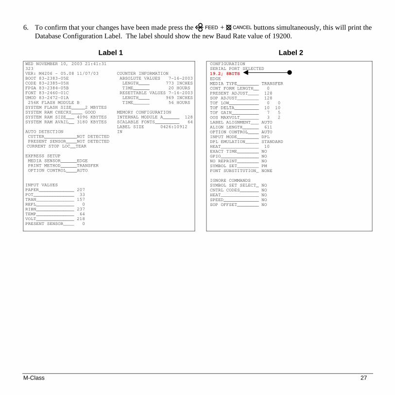
6. To confirm that your changes have been made press the FEED + CANCEL buttons simultaneously, this will print the Database Configuration Label. The label should show the new Baud Rate value of 19200.
Label 1
Label 2
WED NOVEMBER 10, 2003 21:41:31 323 VER: M4206 - 05.08 11/07/03 BOOT 83-2383-05E CODE 83-2385-05H FPGA 83-2384-05B FONT 83-2460-01C UMOD 83-2472-01A 256K FLASH MODULE B SYSTEM FLASH SIZE_____2 MBYTES SYSTEM RAM CHECKS____ GOOD SYSTEM RAM SIZE___ 4096 KBYTES SYSTEM RAM AVAIL__ 3180 KBYTES AUTO DETECTION CUTTER____________NOT DETECTED PRESENT SENSOR____NOT DETECTED CURRENT STOP LOC__TEAR EXPRESS SETUP MEDIA SENSOR______EDGE PRINT METHOD______TRANSFER OPTION CONTROL____AUTO INPUT VALUES PAPER_____________ 207 POT_______________ 33 TRAN______________ 157 REFL______________ 0 RIBN______________ 237 TEMP______________ 64 VOLT______________ 218 PRESENT SENSOR____ 0
COUNTER INFORMATION ABSOLUTE VALUES 7-16-2003 LENGTH____ 773 INCHES TIME______ 20 HOURS RESETTABLE VALUES 7-16-2003 LENGTH____ 969 INCHES TIME______ 56 HOURS MEMORY CONFIGURATION INTERNAL MODULE A______ 128SCALABLE FONTS_________ 64LABEL SIZE 0426:10912 IN
CONFIGURATION SERIAL PORT SELECTED 19.2; 8BITS EDGE MEDIA TYPE________ TRANSFER CONT FORM LENGTH__ 0 PRESENT ADJUST____ 128 SOP ADJUST________ 128 TOF LOW___________ 0 0 TOF DELTA_________ 10 10 TOF GAIN__________ 7 5 OOS MAXVOLT_______ 3 2 LABEL ALIGNMENT___ AUTO ALIGN LENGTH______ 611 OPTION CONTROL____ AUTO INPUT MODE________ DPL DPL EMULATION_____ STANDARD HEAT______________ 10 EXACT TIME________ NO GPIO______________ NO NO REPRINT________ NO SYMBOL SET________ PM FONT SUBSTITUTION_ NONE IGNORE COMMANDS SYMBOL SET SELECT_ NO CNTRL CODES_______ NO HEAT______________ NO SPEED_____________ NO SOP OFFSET________ NO

28 M-Class
4.6 Label Alignment The Label Alignment function is intended for use when the label length is less than the distance between the printhead and the media sensor or where label waste at power-up is a concern. Label Alignment (see table below) is not recommended for label lengths greater than 6.5 inches or for media containing 2 or more form lengths.
Label Stock Label Alignment Setting
Continuous NO
6.5 inches or less YES or AUTO
6.5 inches or more NO
Multiple length labels NO The Label Alignment function is chosen via the menu system (see Section 4.5) or by host commands. The three possible modes, YES, AUTO, and NO, are detailed in the following sections. 4.6.1 Label Alignment = YES In this mode, the operator must supply an ‘ALIGN LENGTH’ value. This value must be physically measured from leading edge to leading edge of two successive labels, as shown. The measurement must be as accurate as possible. For very short labels, errors as small as 0.01” can result in noticeable print variations on the labels between the media sensor and the printhead. The measured value must be sent to the printer via the host computer or entered using the Printer Setup Mode (see Section 4.5). Then, in Normal Mode, press and hold the FEED button (about 4 seconds). The printer will align the label to the top of form position.
Note: If media with a different label length is subsequently loaded, the ‘ALIGN LENGTH’ must be recalculated and re-entered.
M-Class 29
4.6.2 Label Alignment = AUTO In this mode, the printer automatically calculates the ‘ALIGN LENGTH’ thus eliminating the need to physically measure the label. This mode is usually preferred in applications that require frequent media changes to labels of different lengths. To perform an Auto Alignment, in Normal Mode press and hold the FEED button (about 4 seconds). The printer will feed labels to calculate the label length. Following the calculation, the printer will save the measurement and align to the top of form position. Auto Alignment can result in wasted labels during the measurement process (the longer the label length the greater the waste). Auto Alignment with the Present Sensor enabled:
If the printer is equipped with the Present Sensor option and that feature is enabled, while the label length is calculated the printer will pause and illuminate the STOP light after each movement. The operator must press the PAUSE button for the alignment to continue. This allows the operator to remove any labels as required; however, labels should not be forcibly removed since they may not actually be positioned for removal, but at an interim position required for measurement. 4.6.3 Label Alignment = NO When Label Alignment is not enabled (i.e., set to NO), printing begins at the current label position without alignment, assuming the label is at the start of print position. Additionally, if the label length is short, labels between the printhead and the media sensor may be unused.

30 M-Class
4.6.4 Label Alignment Troubleshooting If you experience label alignment problems, the following table offers possible causes and solutions.
Problem Possible Cause Solution Attempting to perform Label Alignment results in no paper movement.
With the Present Sensor enabled, Label Alignment cannot be performed without a Label Length.
Set Label Alignment to AUTO, press and hold FEED until media moves for the automatic length measurement.
~OR~
Re-measure the Label Alignment Length. Use Printer Setup mode to enter the new length. Print a Database Configuration label to ensure the new length has been set.
First label is wasted during alignment. All labels thereafter print to the correct start of print position.
Alignment Length is too long.
~OR~
For labels whose length and stop position cause them to stop between labels on the media sensor, the alignment function can result in wasted labels.
Set Label Alignment to AUTO, press and hold FEED until paper moves for automatic Label Alignment length measurement.
~OR~ Re-measure Label Alignment Length, use Menu Setup to set
new length, ensure desired length has been set.
Obtain a slightly different label Alignment Length measurement. Using the Label Alignment AUTO mode, hold the FEED button to force an alignment and label measurement. Ensuring slack in the label stock may result in a slightly different measurement. The Alignment Length may also be set manually via the Setup Menu. Increasing or decreasing the value by 1 or 2 units (in./100) may help to prevent the wasted labels; however, this may result in incorrect print positions for labels that are short in length.
Label Alignment is incorrect. Pressing
FEED successively results in a short label length, one-inch.
Label Alignment Length is not correct. The default Label Alignment Length is 1.00”, and will result in this behavior when any larger label length is used without setting the appropriate length.
Set Label Alignment to AUTO. Press and hold FEED until paper moves for automatic Label Alignment Length measurement.
~OR~
Measure the label length and use the Setup Menu to set the new length. Print a Database Configuration label to ensure the new length has been set.

M-Class 31
Problem Possible Cause Solution Label Alignment is incorrect. Pressing
FEED successively results in a label length longer than actual, one-inch.
Label Alignment Length is not correct. The default Label Alignment Length is 1.00”, and will result in this behavior when any larger label length is used without setting the appropriate length
Set Label Alignment to AUTO. Press and hold FEED until paper moves for automatic Label Alignment length measurement.
~OR~
Measure the label length and use the Setup Menu to set the new length. Print a Database Configuration label to ensure the new length has been set.
Tear Mode is selected but the label stop position (present position) is not far enough forward.
Another present position has been determined. Enabling the Present Sensor causes the label stop position (present position) to be approximately 0.1” behind the peel bar.
~OR~
The Present Adjust value is not correct.
Disable the Present Sensor.
~OR~
Ensure the host computer is not providing a Present Distance shorter than is required for the Tear Bar.
Use the Setup Menu to modify the Present Adjust value.
Tear Mode is selected but the label stop position (present position) is too far forward.
Another present position has been determined.
~OR~
The Present Adjust value is not correct.
Ensure the host computer is not providing a Present Distance longer than is required for the Tear Bar.
Use the Setup Menu to modify the Present Adjust value.
The ERROR light illuminates during label alignment.
The label supply is empty Load media.

32 M-Class
4.7 Calibration Mode – Button Functions In ‘Calibration’ mode, the buttons allow the printer to adjust to the media being used. Calibration can be performed either automatically or manually, as detailed below.
Notes: Before calibrating, ensure that the Printhead Carrier Assembly is latched down, that the cover is closed, and that the media sensor has been set for the appropriate media type, see Section 4.5.2.
Printer and cutter faults are disabled during and , but can still occur while printing “test” labels.
If at any time you wish to discard your changes and revert back to the previous calibration simply turn off power to the printer. Also, Factory Defaults can be restored, see Section 6.7
To perform Calibration:
Auto Media Calibration (See section 4.7.1)
(Until Paused light turns off)
(See section 4.7.2)
Calibration Mode
Analyze for ‘Paper’
Analyze for ‘Backing or ‘Mark’
Analyze ‘Out of Media’ condition
Prints the ‘Test Label’ for “test”
Media Sensor Calibration
(Press and hold during power-up until the light turns off)STOPCANCEL
PAUSE
Feeds one label for “test”Press andRelease( )FEED
FEED Press andHold( )
CANCEL
Saves the current valuesand resumes Normal Mode+
PAUSE
CANCEL
PAUSE
FEED
CANCEL
Accepts the currentvalues for “test”+
PAUSE
CANCEL
DONE

M-Class 33
4.7.1 Auto Media Sensor Calibration Auto Media Sensor Calibration automatically establishes the optimum sensing values for the media you are using.
Note: Before calibrating, be sure the media sensor is set for the appropriate media type, see Section 4.5.2; also, ensure that the Printhead Carrier Assembly is latched down and the cover is closed.
To automatically calibrate the media sensor: 1. With the desired media loaded, hold the CANCEL button while powering up the printer. Continue to hold the button
until the STOP light turns off then release it. 2. Next press the PAUSE button. The printer will feed approximately ten inches of media to calculate the TOF Delta
and Low values to be used. 3. Upon completion, one of the following lights will flash five times to denote the result of the auto calibration attempt:
STOP light = Successful calibration. Proceed to Step 4.
ERROR light = Unsuccessful calibration, try again. If the calibration continues to fail proceed to Section 4.7.2.
Note: If you wish to discard the changes and revert back to the previous calibration simply turn off the printer before Step 4. 4. Now save the changes and resume by pressing the PAUSE + CANCEL buttons simultaneously and
briefly. Wait until the STOP light goes off.

34 M-Class
4.7.2 Manual Media Sensor Calibration The Manual Media Sensor Calibration procedure should be used in cases where the printer continues to suffer from media sensing problems after performing or attempting to perform the Auto Media Sensor Calibration (see Section 4.7.1).
Note: Before calibrating, be sure the media sensor is set for the appropriate media type, see Section 4.5.2; also, ensure that the Printhead Carrier Assembly is latched down and the cover is closed.
To manually calibrate the media sensor: 1. Hold the CANCEL button and power-up the printer. Continue to hold the button until the STOP light turns off; then
release the button. Next, press and hold the FEED button, continue to hold the button until the STOP light turns on; then release the button.
2. Remove all the material from the media sensor, (see Section 3.3 for the sensor’s location), close the Printhead Carrier
Assembly, and then press the CANCEL button. The printer will flash the ERROR light as it analyzes the no media condition.
3. Position the backing material or the black (reflective) mark in the media sensor, close the Printhead Carrier Assembly,
and then press the FEED button. The printer will flash the ERROR light as it analyzes the top of form mark. 4. Place the media with the backing attached (if any) in the media sensor, close the Printhead Carrier Assembly, and then
press the PAUSE button. The printer will flash the ERROR light as it analyzes the material. 5. Simultaneously and briefly press the PAUSE + CANCEL buttons to accept the calibration for “test” and exit the
. One of the following lights will flash five times to denote the result of the manual calibration attempt:
STOP light = Successful calibration. Proceed to Step 6.
ERROR light = Unsuccessful calibration. Retry the procedure beginning at Step 1.
6. Use the FEED button (feeds a label), and the CANCEL button (prints a test label) to test the current calibration.
Note: If you wish to discard the changes and revert back to the previous calibration simply turn off the printer before Step 7. 7. Now save the changes and resume by pressing the PAUSE + CANCEL buttons simultaneously and
briefly. Wait until the STOP light goes off.

M-Class 35
4.8 Internal Labels The following section details the printer’s internally generated configuration and test labels. 4.8.1 Database Configuration and Test Labels The Database Configuration Label provides valuable printer information including the firmware version, memory allocations, enabled options, and label-counter data.
To print the Database Configuration and Test Labels: With the printer on, loaded with media (at least 4 inches wide) and ribbon (if printing with thermal transfer media), press the FEED + CANCEL buttons simultaneously. The first label printed will be the Database Configuration Label.
Label 1
Label 2 WED NOVEMBER 10, 2003 21:41:31 323 VER: M4206 - 05.08 11/07/03 BOOT 83-2383-05E CODE 83-2385-05H FPGA 83-2384-05B FONT 83-2460-01C UMOD 83-2472-01A 256K FLASH MODULE B SYSTEM FLASH SIZE_____2 MBYTES SYSTEM RAM CHECKS____ GOOD SYSTEM RAM SIZE___ 4096 KBYTES SYSTEM RAM AVAIL__ 3180 KBYTES AUTO DETECTION CUTTER____________NOT DETECTED PRESENT SENSOR____NOT DETECTED CURRENT STOP LOC__TEAR EXPRESS SETUP MEDIA SENSOR______EDGE PRINT METHOD______TRANSFER OPTION CONTROL____AUTO INPUT VALUES PAPER_____________ 207 POT_______________ 33 TRAN______________ 157 REFL______________ 0 RIBN______________ 237 TEMP______________ 64 VOLT______________ 218 PRESENT SENSOR____ 0
COUNTER INFORMATION ABSOLUTE VALUES 7-16-2003 LENGTH____ 773 INCHES TIME______ 20 HOURS RESETTABLE VALUES 7-16-2003 LENGTH____ 969 INCHES TIME______ 56 HOURS MEMORY CONFIGURATION INTERNAL MODULE A______ 128SCALABLE FONTS_________ 64LABEL SIZE 0426:10912 IN
CONFIGURATION SERIAL PORT SELECTED 19.2; 8BITS EDGE MEDIA TYPE________ TRANSFER CONT FORM LENGTH__ 0 PRESENT ADJUST____ 128 SOP ADJUST________ 128 TOF LOW___________ 0 0 TOF DELTA_________ 10 10 TOF GAIN__________ 7 5 OOS MAXVOLT_______ 3 2 LABEL ALIGNMENT___ AUTO ALIGN LENGTH______ 611 OPTION CONTROL____ AUTO INPUT MODE________ DPL DPL EMULATION_____ STANDARD HEAT______________ 10 EXACT TIME________ NO GPIO______________ NO NO REPRINT________ NO SYMBOL SET________ PM FONT SUBSTITUTION_ NONE IGNORE COMMANDS SYMBOL SET SELECT_ NO CNTRL CODES_______ NO HEAT______________ NO SPEED_____________ NO SOP OFFSET________ NO

36 M-Class
The second label printed is the Test Label. This label is used to test the condition of the printhead, as shown below:
Good Print Quality Label: Even pattern consistency indicates correct printhead operation.
Faulty Print Quality Label: Streaks indicate a dirty or faulty printhead. See Section 6.1 for cleaning instructions.

M-Class 37
4.8.2 Test Label The Test Label is used to evaluate the current printer setup for print quality, label tracking, and print positioning.
To print the Test Label:
With the printer loaded with media (at least 4 inches wide), and ribbon (if printing with thermal transfer media), simultaneously press the PAUSE + FEED buttons.

38 M-Class

M-Class 39
5.0 Introduction Controlling Printer Settings with the Internal Printserver
If your printer is equipped with the optional Internal Printserver, many of the printer’s setting and parameters can be modified and controlled via the built-in HTML pages resident in the printer. These pages can be accessed using any web browser by simply entering the IP address in the URL bar. The front panel is comprised of three indicator lights, a Liquid Crystal Display and five mode-dependant keys. The selectable modes (Ready, Menu and Quick Test) and the related functions of the printer keys are detailed below.
Note: To Adjust the LCD contrast, press and hold the MENU key for 10 to 20 seconds to modify the LCD contrast level.
5.0.1 Ready Mode: Normal Operation (Ready Light ‘On’)
The PAUSE Key temporarily suspends printing. Pressing it again will return the printer to normal operation.
The FEED Key advances one label, and clears any corrected faults.
Pressing and holding causes the printer to perform a Quick Media Calibration; see Section 5.4.1.
The CANCEL Key ‘pauses’ the printer and then prompts you for confirmation. If yes, the current job is cancelled. The printer remains paused.
Pressing and holding four seconds will reset the printer and clear temporary host settings (soft reset).
MENU The MENU Key toggles between the Ready and Menu Modes. In the Ready Mode, pressing and holding four seconds will change the display contrast.
The TEST Key enters (or exits) the Quick Test Menu.
40 M-Class
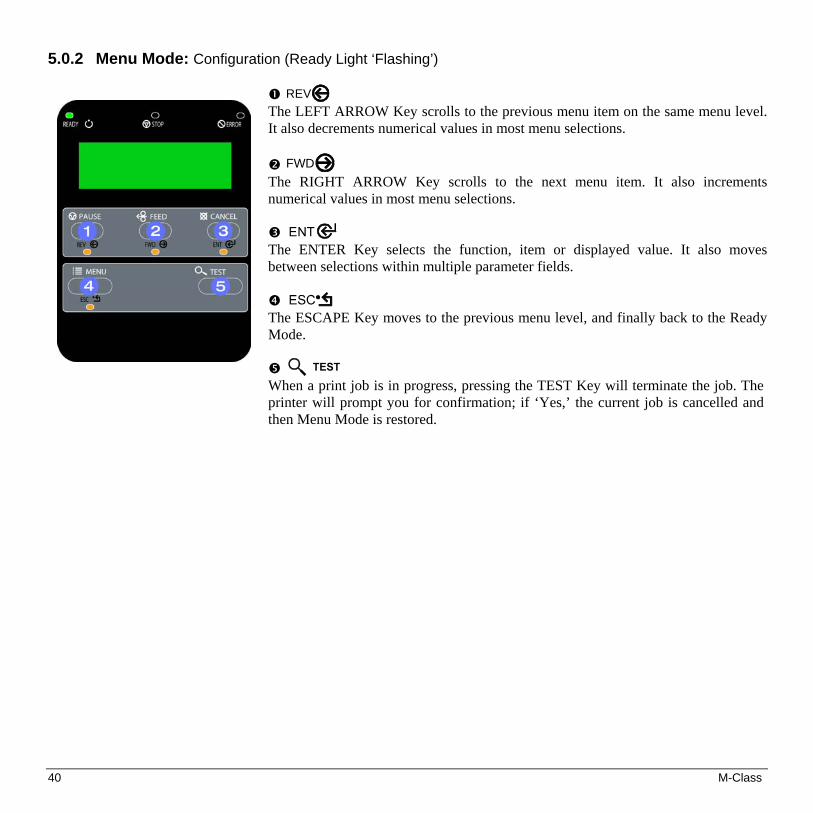
5.0.2 Menu Mode: Configuration (Ready Light ‘Flashing’)
REV The LEFT ARROW Key scrolls to the previous menu item on the same menu level. It also decrements numerical values in most menu selections.
FWD The RIGHT ARROW Key scrolls to the next menu item. It also increments numerical values in most menu selections.
The ENTER Key selects the function, item or displayed value. It also moves between selections within multiple parameter fields.
The ESCAPE Key moves to the previous menu level, and finally back to the Ready Mode.
When a print job is in progress, pressing the TEST Key will terminate the job. The printer will prompt you for confirmation; if ‘Yes,’ the current job is cancelled and then Menu Mode is restored.

M-Class 41
5.0.3 Quick Test Mode: Print Test Labels
Note: The Quick Test Mode functions are disabled while processing data from communications interfaces until the Host Timeout value expires. Also, You can program a time delay between the printings of test labels using the ‘Print Test Rate’ feature; see Section 5.1.7
REV The LEFT ARROW Key scrolls to the previous test function.
FWD
The RIGHT ARROW Key scrolls to the next test function.
The ENTER Key will change the selected test label quantity of 2, 100, 1000, or 9999 (except the ‘Configuration Label’, quantity of one). Holding down the key scrolls quantities.
The ESCAPE Key will exit the Quick Test Mode without printing.
The TEST Key will print the selected test label at the selected quantity. During test label printing, this key also functions as a cancel key (the printer will prompt you for confirmation before cancellation occurs).

42 M-Class
5.0.4 Indicator Lights
‘On’ indicates that the printer is powered ‘On’ and, after initialization, it indicates the Ready Mode.
‘Slow Flashing’ indicates Menu Mode.
‘Fast Flashing’ indicates data is being received and processed.
‘On’ indicates a ‘Paused’ condition.
‘Slow Flashing’ indicates a Warning. ‘Fast Flashing’ indicates a Fault. See Section 7.1 for a listing of associated messages.
5.0.5 LCD
Liquid Crystal Display
The display provides several types of information: • Following a brief power-up sequence (initialization), the ‘Ready’ message. • The time and date, if the printer has received it from one of the following: the
host, the front panel setting, or the Time and Date option. • A label counter during a batch print job. • The Menu System when in Menu Mode. • Any prompt, condition, downloading, warning, or fault message.

M-Class 43
5.1 The Menu System
Printer operation can be controlled through the user interface, allowing the operator access to these six menu system branches: Media Settings; Print Control; Printer Options; System Settings; Communications; and, Diagnostics. While in the menu system, the current selection will be indicated with an asterisk (*) next to the displayed item on the LCD. Selections designated with a section symbol (§) will require a printer reset before becoming effective. A reset will be automatically invoked when exiting the menu system and answering ‘Yes’ to the ‘Save Changes’ prompt. Changes made will be saved. When power is removed, the new settings will be restored upon power-up. The same functional commands from your host computer may, in some cases, override the printer’s menu settings. In addition, as a security feature for the prevention of accidental or unauthorized changes, the menu system has a password protection feature.
Note: In the following subsections, the factory default settings are denoted with the ‘ ’ symbol. Selections denoted with a diamond (♦) can only be changed through the menu system - all other selections can be overridden by host software commands. Consult the Class Series Programmer’s Manual for specific information.
5.1.1 Entrance and Exit Prompts
With ‘Ready’ displayed on the LCD, press the MENU Key to enter Menu Mode.
Note: While in Menu Mode, the printer will stop processing new DPL (or bitmapped) data.
MENU MODE
Depending upon the configuration of the printer, the following Entrance and Exit Prompts may be displayed when accessing or leaving the Menu System.
ENTER PASSWORD 0 0 0 0
You are attempting to enter Menu Mode. Security has been enabled and now the correct user-definable password is required before accessing the Menu Mode functions.
KEEP HOST CHANGES? ENTER = YES
You are now entering Menu Mode. Existing Host commands have affected the configuration of the printer. Pressing ENTER will save these changes; otherwise, the printer will revert to previously saved settings.
SAVE CHANGES? ENTER = YES
You are now exiting Menu Mode, but have made changes to the printer’s settings. Pressing ENTER will reconfigure your printer according to these changes; otherwise, the printer will revert to previously saved settings.
Note: If changes have been made that require a reset, the printer will automatically invoke that reset.

44 M-Class
5.1.2 Media Settings MEDIA TYPE
Selects the printing method.
DIRECT THERMAL
For use with heat sensitive media.
THERMAL TRANSFER For use with media requiring a ribbon to create an image.
SENSOR TYPE Selects the top-of-form (TOF) sensing method for the media.
GAP The printer recognizes the TOF by sensing gaps in the media.
CONTINUOUS No TOF sensing. The LABEL LENGTH setting determines the length.
REFLECTIVE The printer recognizes the TOF by sensing reflective (black) marks on the media.
LABEL LENGTH 04.00in (0-99.99)
When the Sensor Type is set to Continuous, this value is used to determine the TOF.
MAXIMUM LABEL LENGTH 16.00in (0-99.99)
Sets the maximum length between TOF marks (gap or reflective). If this limit is exceeded, a top of form fault is declared.
PAPER OUT DISTANCE 00.25in (0-99.99)
Sets the length of travel before an out of stock condition is declared.
LABEL WIDTH 203DPI > 04.26in (.75-4.26) 300DPI > 04.16in (.75-4.16)
Sets the maximum limit for the printable width. Objects extending beyond this limit will be clipped off and not printed.
RIBBON LOW DIAMETER ♦ 1.38 in (1.00-2.00)
Sets the threshold for a low ribbon indication.
SENSOR CALIBRATION ♦
Adjusts the printer to sense your media.
PERFORM CALIBRATION The user follows steps to allow the printer to calculate the empty, gap (or mark), and paper values to set the media sensor.
ADVANCED ENTRY The user directly inputs the best values to adjust the media sensor.
SENSOR LEVELS Sets threshold values for the media sensor parameters. Manual entry for paper, gap (or mark), and empty thresholds.
SENSOR GAIN Observe A/D reading and set SENSOR GAIN. Adjusts the sensitivity of the sensor for custom label stock.
M-Class 45
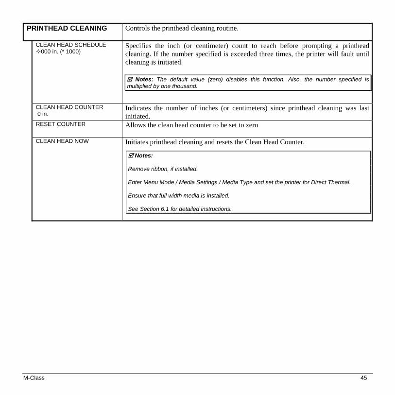
PRINTHEAD CLEANING
Controls the printhead cleaning routine.
CLEAN HEAD SCHEDULE 000 in. (* 1000)
Specifies the inch (or centimeter) count to reach before prompting a printhead cleaning. If the number specified is exceeded three times, the printer will fault until cleaning is initiated.
Notes: The default value (zero) disables this function. Also, the number specified is multiplied by one thousand.
CLEAN HEAD COUNTER 0 in.
Indicates the number of inches (or centimeters) since printhead cleaning was last initiated.
RESET COUNTER Allows the clean head counter to be set to zero
CLEAN HEAD NOW Initiates printhead cleaning and resets the Clean Head Counter.
Notes: Remove ribbon, if installed. Enter Menu Mode / Media Settings / Media Type and set the printer for Direct Thermal. Ensure that full width media is installed. See Section 6.1 for detailed instructions.

46 M-Class
5.1.3 Print Control HEAT
10 (0-30) Controls the ‘burn-time’ of the printhead. This is the equivalent of Heat Setting on most label software programs.
PRINT SPEED M-4206 > 6 in/s (2-6) M-4208 > 8 in/s (2-8) M-4306 > 6 in/s (2-6)
Controls the rate of label movement during the printing process.
FEED SPEED M-4206 > 6 in/s (2-6) M-4208 > 8 in/s (2-8) M-4306 > 6 in/s (2-6)
Controls the rate of label when the FEED Key is pressed.
REVERSE SPEED M-4206 > 4 in/s (2-5) M-4208 > 4 in/s (2-5) M-4306 > 4 in/s (2-5)
Controls the rate of label movement during backup positioning for start of print, cutting or present distance.
ROW OFFSET 00.00in (0-99.99)
Shifts the vertical start of print position. This is the user setting for row adjustment.
COLUMN OFFSET 00.00in (0-99.99)
Shifts the horizontal, left-justified start of print position to the right without shifting the Label Width termination point to the right. This is the user setting for Column Adjust.
PRESENT DISTANCE 0.00in (0-4.00)
Sets the label stop position past the start of print. When the next label format is received, it will automatically be back fed to the start position. If the present distance is set to zero, the printer will operate without reversing.
CUSTOM ADJUSTMENTS ♦ These factory adjustments independently change the listed parameters to finely tune the printer and compensate for slight mechanical differences sometimes evident if multiple printers share label formats.
DARKNESS 32 (1-64)
Controls the printhead strobe time to fine-tune the HEAT setting.
CONTRAST 32 (1-64)
It allows relative print edge (gray) adjustment for the print quality, which allows fine-tuning for specific media/ribbon mix.
ROW ADJUST 000 DOTS (-150 -150)
Shifts the vertical start of print position in dots upward or downward to fine-tune the ROW OFFSET setting.
COLUMN ADJUST 000 DOTS (0-128)
Shifts both the horizontal start of print position and the LABEL WIDTH termination point to the right in dots to fine-tune the COLUMN OFFSET setting.
PRESENT ADJUST 064 DOTS (0-128)
Adjusts the label stopping position in dots to fine-tune the PRESENT DISTANCE setting.

M-Class 47
5.1.4 Printer Options MODULES
Memory available for user storage of graphics, fonts and label formats. (The physical presence of the respective memory module must be detected to show the function selections in the menu system.
PRINT DIRECTORY Prints a label directory of selected, or of all available modules, the available space on these modules, the files present, and the type of module and files.
PRINT FILE The user may select from a list of available files for sample printing.
FORMAT MODULE The user may select from a list of available modules for formatting – all data will be erased.
DELETE FILE The user may select from a list of available files for deleting (protected modules will not appear). Bytes will not be retrieved until the module that contained the deleted file is packed.
PACK MODULE Packing the module removes files marked as deleted and defragments existing file structures to recover space.
PRESENT SENSOR
Used for on-demand label dispensing, where a printed label blocking the sensor will inhibit further printing until removed. (The physical presence of the Present Sensor must be detected to show the ENABLE/DISABLE selections, else NOT INSTALLED will be displayed momentarily).
MODE
Sets Present Sensor to desired mode of operation.
AUTO
Enables the present sensor when option is installed – present sensor or peel and present mechanism. Stop location (present distance is automatically set appropriately for the installed hardware.
ENABLED
Enables the sensor for on-demand printing. Stop location (present distance is automatically set appropriately for the installed hardware.
DISABLED
Disables the sensor.
RETRACTION DELAY 070 x 10mS (1-255)
Time delay prior to moving label to next start of print in milliseconds.

48 M-Class
CUTTER
Used to cut media into separate labels. (The physical presence of a device must be detected to show the ENABLE/DISABLE selections, else NOT INSTALLED will be momentarily displayed).
AUTO
Enables the cutter when option is installed. Stop location (present distance is automatically set appropriately for the installed hardware.
ENABLED
Enables cutting.
DISABLED
Disables cutting.
GPIO PORT ♦
Used to interface the printer to external controlling devices (see Appendix D).
GPIO DEVICE
Sets the GPIO Port to work with a specific type of device.
DISABLED
Disables the GPIO Port.
APPLICATOR
Enables the GPIO for a label applicator.
BARCODE VERIFIER
Enables the GPIO for a bar code verifier.
START OF PRINT
Programmable signal input that controls the Start of Print (SOP) process.
ACTIVE HIGH
SOP signal must go ‘high’ for at least 50 milliseconds to initiate printing.
ACTIVE LOW
SOP signal must go ‘low’ for at least 50 milliseconds to initiate printing.
END OF PRINT
Programmable signal output that signifies the End of Print (EOP) process.
LOW PULSE
Outputs a low pulse (approximately 30 milliseconds long) following printing.
HIGH PULSE
Outputs a high pulse (approximately 30 milliseconds long) following printing.
ACTIVE LOW
Outputs a logic ‘low’ following printing.
ACTIVE HIGH
Outputs a logic ‘high’ following printing.

M-Class 49
5.1.5 System Settings
CONFIGURATION FILE ♦
Options for storage and recall of printer configuration files. See Appendix E for details.
RESTORE AS CURRENT Provides a list of available configuration files. Selecting a file from the list causes a printer reset; afterward, the printer is configured according to the activated file.
SAVE SETTING AS Saves the entire effective configuration of the printer to a file. Unique names with up to nineteen characters are possible.
DELETE FILE Provides a list of available configuration files. Files selected are immediately removed, freeing the module.
Note: A currently activated file cannot be deleted.
FACTORY SETTING FILE Provides a list of available configuration files. The selected file will be restored whenever a Level 1 reset is performed; see Section 6.7.
INTERNAL MODULE D 1024 KB (100-5120)
Sets the number of 1K blocks allocated for the internal RAM ‘D’ module.
DEFAULT MODULE D
Sets the default module used to store files when no other module is specified. Available choices are G=FLASH memory or D=RAM memory
SCALEABLE FONT CACHE 0312 KB (100-5120)
Sets the number of 1K blocks allocated for the scaleable font engine. Available memory dependent upon model.
SINGLE BYTE SYMBOLS
Selects the code page used to print single byte fonts unless otherwise specified in DPL.
PC_850 MULTILINGUAL One of many selectable standard sets; see the Class Series Programmer’s Manual for details.
DOUBLE BYTE SYMBOLS
When equipped with the ILPC option, this selects the code page used to print double byte fonts unless otherwise specified in DPL; see the Class Series Programmer’s Manual.
UNICODE
Unicode (including Korean)
GB Government Bureau Industry Standard; Chinese (PRC)
BIG 5
Taiwan encoded
JIS
Japanese Industry Standard
SHIFT JIS
Shift Japanese Industry Standard
EUC
Extended UNIX Code
TIME AND DATE
Allows the user to set the time and date.

50 M-Class
System Settings (continued)
MEDIA COUNTERS ♦ Internal record of inches printed and time of use.
ABSOLUTE COUNTER Shows the number of inches printed since being set at the factory. Not resettable.
RESETTABLE COUNTER The number of inches printed since the last reset. User resettable.
RESET COUNTER
Resets the Resettable Counter to zero.
PRINT CONFIGURATION Prints the effective configuration of the system. In addition, if settings were changed that require a reset to become effective, this will be indicated with the ‘§’ symbol. A bulleted item (•) indicates that it was changed via the host, but not saved in non-volatile memory.
CONFIGURATION LEVEL ♦ To upgrade the application program (resident software) version of the printer, the hardware and software compatibility levels must match for the update to be accepted. This information is displayed here; it is also printed on a configuration label. Each printer has a unique Key number in the following form:
vvvv-cwxx-yyyyyy-zzz
Where:
vvvv – represents the model number of the application loaded
cwxx – represents the hardware / software feature level, where:
c – represents the printer class.
w – represents hardware feature level of the main board.
xx – represents the software feature level. Software feature levels are accepted up to the ‘xx’ value (increases beyond this level require an authorization code)
10 = Standard DPL 20 = Internal CG Times Font
yyyyyy – is a manufacturing date code
PRINTER KEY
zzz – is a unique time stamp
APPLICATION VERSION Displays the Application version of the printer’s firmware. BOOT LOADER Displays the Boot Loader version of the printer’s firmware. UPGRADE PRINTER CODE This function is used to upgrade the software feature level of the printer. Datamax
authorization is required. UNLOCK FEATURE This function is used to unlock the additional optional features within the printer.
Datamax authorization is required.

M-Class 51
System Settings (continued)
SET FACTORY DEFAULTS Parameters in this menu listing with the ‘ ’ symbol are the designated defaults.
SET FACTORY DEFAULTS Overwrite the current settings with the factory default settings or, if selected, will restore the Factory Setting File.
Note: The reset will be automatic. If no Factory Setting File is used, all menu settings will be restored except CUSTOM ADJUSTMENTS, and the media and ribbon sensor calibrations.
FORMAT ATTRIBUTES
Affects the manner in which overlapping text and graphics are treated as the label is printed. Consult the Class Series Programmer’s Manual for details.
XOR Intersecting text strings, images, and bar codes print on top of one another.
OPAQUE Interacting text strings, images, and bar codes are obliterated by those formatted last. Each character cell is treated as opaque.
TRANSPARENT Intersecting text strings, images, and bar codes will not be printed. (An odd number of overlapping objects will print.)
LABEL ROTATION ♦
Instructs the printer to rotate the label format 180 degrees before printing.
ENABLED Label formats are flipped top to bottom.
DISABLED Label formats are printed normally.
IMAGING MODE ♦
Instructs the printer whether to pre-image the label format.
Note: This selection can affect the accuracy of time-stamped labels and throughput.
MULTIPLE LABEL The printer images multiple labels as memory permits, achieving the fastest throughput; however, if time-stamping, the time will reflect the moment the label is imaged rather than when actually printed.
SINGLE LABEL The printer images the next label only after the previous label has been successfully printed. Single processing provides time-stamps that are more accurate, but it slows label throughput time.
PAUSE MODE When enabled, suspends printing between each label until the PAUSE Key is pressed.
ENABLED Requires an operator press the PAUSE Key after each label.
DISABLED The printer completes label batch without pausing between labels.
52 M-Class
System Settings (continued)
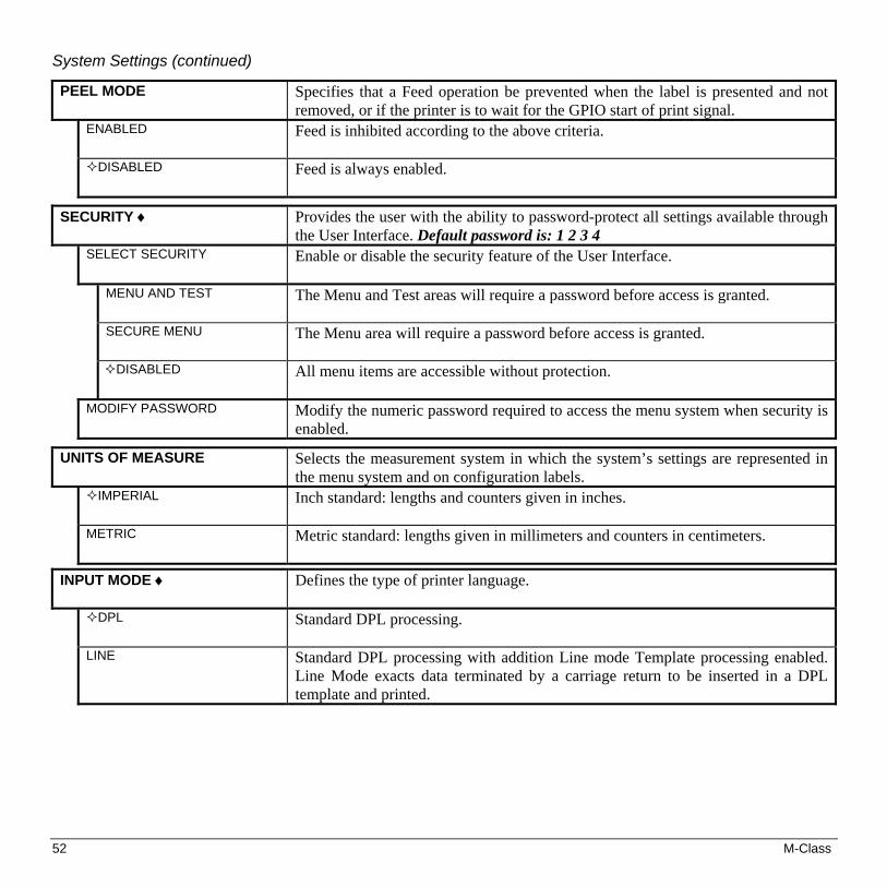
PEEL MODE Specifies that a Feed operation be prevented when the label is presented and not removed, or if the printer is to wait for the GPIO start of print signal.
ENABLED Feed is inhibited according to the above criteria.
DISABLED Feed is always enabled.
SECURITY ♦ Provides the user with the ability to password-protect all settings available through the User Interface. Default password is: 1 2 3 4
SELECT SECURITY Enable or disable the security feature of the User Interface.
MENU AND TEST
The Menu and Test areas will require a password before access is granted.
SECURE MENU
The Menu area will require a password before access is granted.
DISABLED
All menu items are accessible without protection.
MODIFY PASSWORD Modify the numeric password required to access the menu system when security is enabled.
UNITS OF MEASURE Selects the measurement system in which the system’s settings are represented in the menu system and on configuration labels.
IMPERIAL Inch standard: lengths and counters given in inches.
METRIC Metric standard: lengths given in millimeters and counters in centimeters.
INPUT MODE ♦
Defines the type of printer language.
DPL Standard DPL processing.
LINE
Standard DPL processing with addition Line mode Template processing enabled. Line Mode exacts data terminated by a carriage return to be inserted in a DPL template and printed.

M-Class 53
System Settings (continued)
DPL EMULATION ♦ (not available with M-4306)
Determines SOP Emulation (start of print (<STX>O)) see above, Column Emulation (see above), positions barcodes as does selected printer.
STANDARD
Start of print 220; the below exceptions are disabled.
ALLEGRO PRODIGY PLUS PRODIGY
Allegro, Prodigy Plus, and Prodigy emulations enabled:
• Data Terminator – I 2 of 5 Barcodes (IDs D, J, and L), the first non-numeric character processed will terminate the barcode data field.
• Bar Size – I 2 of 5 Barcode (ID L), when the bar size is specified greater than P (25), the size is automatically decreased to 10.
• Human Readable Fonts – The EAN and UPC barcodes (IDs B, C, F, G, M, and N) print a fixed font size.
• Lines and boxes: Rotations 2 and 4 are affected by the vertical multi-plication factor defined in the DPL Dxx command.
• Column positions greater than the printhead width are adjusted back to the printable area and printed.
• Barcodes (rotation 3, upside down / right to left) with row position less than barcode height result in row position equal to barcode height, that is, barcodes falling off label leading edge are pushed back onto the label.
• <STX>L (Label Command) followed by no printable fields result in no paper movement. (When disabled a blank label is printed).
Allegro Only:
• The row position is calculated based on 194 DPI.
COLUMN EMULATION ♦ * Not available in M-4306
Compensation for location of column position 0 via columnar dots per inch (dpi) emulation.
203 in (180 - 250)
Dpi emulation, smaller numbers shrink text from right to left.
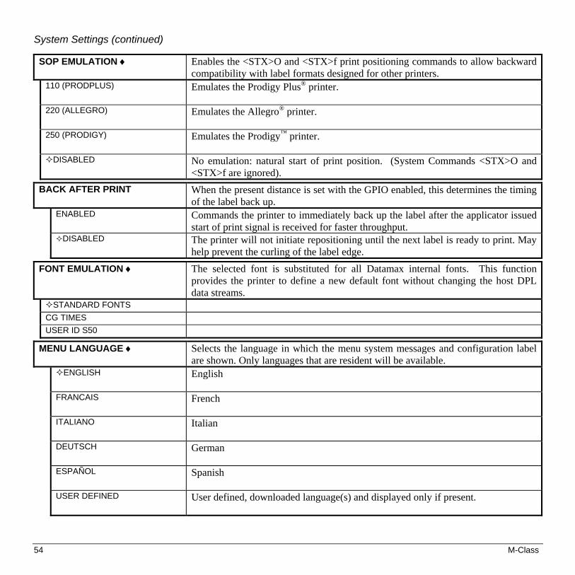
54 M-Class
System Settings (continued)
SOP EMULATION ♦
Enables the <STX>O and <STX>f print positioning commands to allow backward compatibility with label formats designed for other printers.
110 (PRODPLUS)
Emulates the Prodigy Plus® printer.
220 (ALLEGRO)
Emulates the Allegro® printer.
250 (PRODIGY)
Emulates the Prodigy™ printer.
DISABLED
No emulation: natural start of print position. (System Commands <STX>O and <STX>f are ignored).
BACK AFTER PRINT
When the present distance is set with the GPIO enabled, this determines the timing of the label back up.
ENABLED
Commands the printer to immediately back up the label after the applicator issued start of print signal is received for faster throughput.
DISABLED
The printer will not initiate repositioning until the next label is ready to print. May help prevent the curling of the label edge.
FONT EMULATION ♦
The selected font is substituted for all Datamax internal fonts. This function provides the printer to define a new default font without changing the host DPL data streams.
STANDARD FONTS CG TIMES USER ID S50
MENU LANGUAGE ♦ Selects the language in which the menu system messages and configuration label are shown. Only languages that are resident will be available.
ENGLISH
English
FRANCAIS
French
ITALIANO
Italian
DEUTSCH
German
ESPAÑOL
Spanish
USER DEFINED
User defined, downloaded language(s) and displayed only if present.
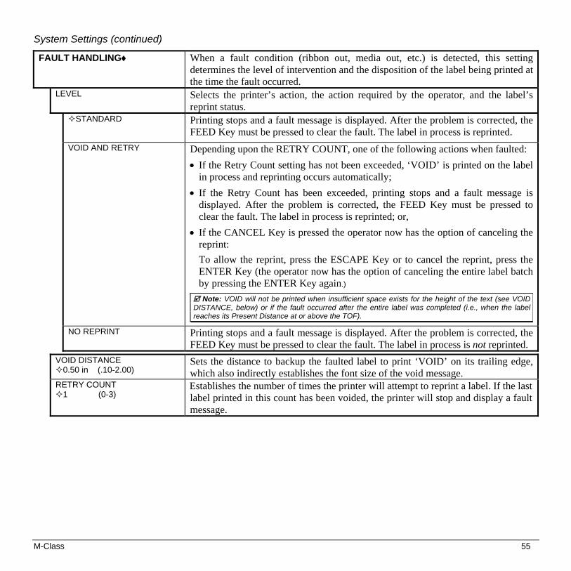
M-Class 55
System Settings (continued)
FAULT HANDLING♦
When a fault condition (ribbon out, media out, etc.) is detected, this setting determines the level of intervention and the disposition of the label being printed at the time the fault occurred.
LEVEL
Selects the printer’s action, the action required by the operator, and the label’s reprint status.
STANDARD
Printing stops and a fault message is displayed. After the problem is corrected, the FEED Key must be pressed to clear the fault. The label in process is reprinted.
VOID AND RETRY
Depending upon the RETRY COUNT, one of the following actions when faulted:
• If the Retry Count setting has not been exceeded, ‘VOID’ is printed on the label in process and reprinting occurs automatically;
• If the Retry Count has been exceeded, printing stops and a fault message is displayed. After the problem is corrected, the FEED Key must be pressed to clear the fault. The label in process is reprinted; or,
• If the CANCEL Key is pressed the operator now has the option of canceling the reprint:
To allow the reprint, press the ESCAPE Key or to cancel the reprint, press the ENTER Key (the operator now has the option of canceling the entire label batch by pressing the ENTER Key again.)
Note: VOID will not be printed when insufficient space exists for the height of the text (see VOID DISTANCE, below) or if the fault occurred after the entire label was completed (i.e., when the label reaches its Present Distance at or above the TOF).
NO REPRINT
Printing stops and a fault message is displayed. After the problem is corrected, the FEED Key must be pressed to clear the fault. The label in process is not reprinted.
VOID DISTANCE 0.50 in (.10-2.00)
Sets the distance to backup the faulted label to print ‘VOID’ on its trailing edge, which also indirectly establishes the font size of the void message.
RETRY COUNT 1 (0-3)
Establishes the number of times the printer will attempt to reprint a label. If the last label printed in this count has been voided, the printer will stop and display a fault message.
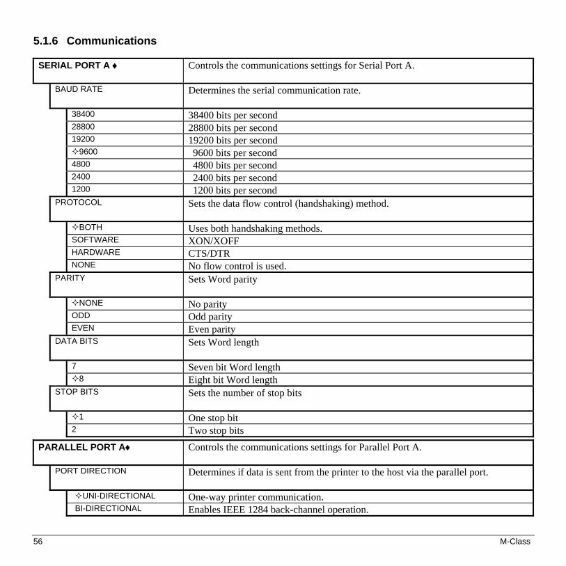
56 M-Class
5.1.6 Communications SERIAL PORT A ♦ Controls the communications settings for Serial Port A.
BAUD RATE
Determines the serial communication rate.
38400 38400 bits per second 28800 28800 bits per second 19200 19200 bits per second
9600 9600 bits per second 4800 4800 bits per second 2400 2400 bits per second 1200 1200 bits per second
PROTOCOL Sets the data flow control (handshaking) method.
BOTH Uses both handshaking methods. SOFTWARE XON/XOFF HARDWARE CTS/DTR NONE No flow control is used.
PARITY
Sets Word parity
NONE No parity ODD Odd parity EVEN Even parity
DATA BITS
Sets Word length
7 Seven bit Word length 8 Eight bit Word length
STOP BITS
Sets the number of stop bits
1 One stop bit 2 Two stop bits
PARALLEL PORT A♦ Controls the communications settings for Parallel Port A.
PORT DIRECTION Determines if data is sent from the printer to the host via the parallel port.
UNI-DIRECTIONAL One-way printer communication. BI-DIRECTIONAL Enables IEEE 1284 back-channel operation.

M-Class 57
Communications (continued)
NIC ADAPTER♦ Network Interface Card Adapter (optional). If not present, this displays ‘NOT INSTALLED’ when accessed. After making changes to these parameters, save the changes, exit the menu system, the printer will then reset for the changes to take effect.
IP ADDRESS The static IP address of the NIC Adapter. This is in standard dotted-decimal format.
SUBNET MASK The static subnet assigned to the NIC Adapter.
GATEWAY Specifies the network gateway address the NIC Adapter should use.
SNMPTRAP DESTINATION
Selects the Network IP address where all SNMP Traps will be sent. If zeroed, no traps are sent. The Receiver must have SNMP service installed.
IP DISCOVERY This is the address discovery method used by the NIC Adapter if a static address is not utilized. If no server for any of the discovery methods is found, the static value specified is used.
Note: For faster NIC Adapter boot times, disable any discovery methods not used.
ENABLED
Default. Modifications to IP, Subnet Mask, or Gateway addresses will not be allowed.
WARNING! An IP Address assigned by a server has precedence over any static IP Address stored in the NIC Adapter.
DISABLED
Disables IP Discovery.
Note: Select this option to ensure that any stored static IP is used by the NIC Adapter.
SET FACTORY DEFAULTS Resets all of the network parameters to factory default settings. Including some parameters that are not accessible through the printer’s menu.
Not
ava
ilabl
e w
hen
“IP
Dis
cove
ry” i
s en
able
d

58 M-Class
Communications (continued)
HOST SETTINGS ♦ Settings which affect all communications with a host.
HOST TIMEOUT 10 SEC (1-60)
The number of seconds a communications port must be idle before the printer may process data from a different port. This value is also used to “timeout” an image / label format download (i.e., if, at any time, data flow stops before a complete label format is received, the data will be ignored).
CONTROL CODES Allows the operator to change the prefix of the software commands interpreted by the printer.
STANDARD CODES Hex 01 = SOH command; Hex 02 = STX command; count-by = ^; Hex 1B = ESC; Hex 0x0D = Carriage Return
ALTERNATE CODES Hex 5E = SOH command; Hex 7E = STX command; count-by = @; Hex 1B = ESC; Hex 0x0D = Carriage Return
ALTERNATE CODES 2 Hex 5E = SOH command; Hex 7E = STX command; count-by = @; Hex 1B = ESC; Hex 0x7C = Carriage Return
CUSTOM CODES Each DPL command (SOH, STX, CR, and count-by) may be selected by entering the desired Hex code. (The and Keys will scroll the characters, while the ENTER Key selects character and then advances the cursor.)
FEEDBACK CHARACTERS Returns a Hex 1E, [RS], after each label successfully prints, and a Hex 1F, [US], after each batch of labels is printed.
ENABLED
Feedback characters are sent to the host.
DISABLED
No feedback characters are sent.
ESC SEQUENCES Allows data containing invalid ESC control code sequences to be processed, helpful because some systems send a “banner” to the printer.
ENABLED
Normal printer operating mode.
DISABLED ESC sequences are ignored and the data is processed. Bitmapped font downloads are disabled in this mode.
HEAT COMMAND Allows the user to disable the DPL Heat Command, providing compatibility with other DATAMAX printers.
ENABLED
Normal printer operating mode.
DISABLED DPL Heat commands are ignored. The heat value is controlled via the menu setting; see Section 5.1.3.
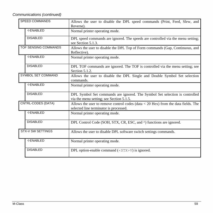
M-Class 59
Communications (continued)
SPEED COMMANDS Allows the user to disable the DPL speed commands (Print, Feed, Slew, and Reverse).
ENABLED
Normal printer operating mode.
DISABLED DPL speed commands are ignored. The speeds are controlled via the menu setting; see Section 5.1.3.
TOF SENSING COMMANDS Allows the user to disable the DPL Top of Form commands (Gap, Continuous, and Reflective).
ENABLED
Normal printer operating mode.
DISABLED DPL TOF commands are ignored. The TOF is controlled via the menu setting; see Section 5.1.2.
SYMBOL SET COMMAND Allows the user to disable the DPL Single and Double Symbol Set selection commands.
ENABLED
Normal printer operating mode.
DISABLED DPL Symbol Set commands are ignored. The Symbol Set selection is controlled via the menu setting; see Section 5.1.5.
CNTRL-CODES (DATA) Allows the user to remove control codes (data < 20 Hex) from the data fields. The selected line terminator is processed.
ENABLED
Normal printer operating mode.
DISABLED DPL Control Code (SOH, STX, CR, ESC, and ^) functions are ignored.
STX-V SW SETTINGS Allows the user to disable DPL software switch settings commands.
ENABLED
Normal printer operating mode.
DISABLED DPL option-enable command (<STX>V) is ignored.

60 M-Class
5.1.7 Diagnostics HEX DUMP MODE ♦ Most commonly used for troubleshooting. Prints data and instructions received
from the host rather than interpreting them as label formats; see Section 7.2. ENABLED Prints raw ASCII data received from the host rather than executing the commands.
DISABLED Executes and prints label formats (normal operating mode).
OPTIONS TESTING ♦ Allows or performs diagnostics of specific options within the printer.
TEST PRESENT SENSOR Performs a functional test of the present sensor.
TEST CUTTER Performs a functional test of the cutter.
PERFORM TEST 1 TIME
The test will cycle the selected number of times (1, 10, or 100) with the results displayed following each attempt.
PRINT TEST RATE (min) ♦ 000 (0-120)
The number of minutes to delay between the printing of batches of Quick Test Labels.
SENSOR READINGS ♦
Analog Sensor readings are displayed.
THR TRAN RIBM 24V PS HD RANK 255 255 255 255 255 255 255
Live sensor values are displayed. Maximum values are shown in this example, where: THR = thermistor sensor; TRAN = transmissive (gap) media sensor (REFL is shown if the SENSOR TYPE is set to ‘reflective’); RIB M = ribbon motion sensor; 24V = 24 volt DC power supply sensor; PS = Present sensor; HD = head-down sensor; and, RANK = the value of the printhead ranking resistor.
RIBBON SENSOR LIMITS ♦ Displays ribbon sensor ADC low and high values used for motion detection.
RIBBON ADC LOW HIGH 070 164
Approximate default values are shown here (actual values will vary).

M-Class 61
5.1.8 MCL Options MCL AT POWER-UP ♦ MCL (Macro Command Language) is tool suite designed for data collection
applications. The printer will accept input data from peripheral devices and the application can request and send data to locally resident lookup files or remote databases.
ENABLED After power to the printer is turned ‘Off’ and ‘On,’ MCL will be started. The printer is now ready to accept input data from peripheral devices such as barcode scanners, weigh scales, and keyboards without the need of a host computer.
DISABLED Normal printer functions.
START MCL ♦ MCL with be started after exiting from the menu.

62 M-Class
5.2 Display Messages The printer displays several different types of information (if not in the menu system or Quick Test Mode): User Prompts and Condition Messages (also see Section 5.1.1 for a listing of the Enter/Exit Prompts)
Application and Boot Loader Updating Messages (see Section 6.8)
Fault and Warning Messages (see Section 7.1)
5.2.1 User Prompts and Condition Messages User Prompts alert the operator to a required action. Condition Messages are used to indicate an operational state.
User Prompts and Condition Messages
Displayed Message Description Condition(s) !
!!DMFBSJOH!GBVMUT!
!
The printer is trying to clear a fault condition.
Occurs when the FEED Key is pressed after the correction of a fault.
!
!DBMJCSBUJOH!
A media calibration is being performed.
The FEED Key was pressed and held.
!
DBODFM!SFQSJOU@!FOUFS!LFZ!>!ZFT!
!
The CANCEL or TEST Key was pressed during the fault handling process.
The faulted label will be cancelled if ENTER is pressed, then the remaining labels in the batch will be printed.
!
DBODFM!CBUDI@!FOUFS!LFZ!>!ZFT!
!
The CANCEL or TEST Key was pressed during a batch job.
The current print batch will be cancelled if ENTER is pressed; the remaining labels will not be printed.
!
!QBVTFE!
The printer is paused or offline.
The printer is in a paused condition.

M-Class 63
User Prompts and Condition Messages
Displayed Message Description Condition(s) !
!SFBEZ!
!
Ready Mode.
Normal operating mode. The printer is ready to receive and process label formats.
!
!SFNPWF!MBCFM!
!
A label is awaiting removal.
The Present Sensor option is enabled and a label blocks the sensor. Remove the label to continue printing.
!
TZTUFN!JOJUJBMJ[JOH!
!
Normal power-up and soft reset condition.
Follows the ‘SYSTEM RESET IN PROGRESS’ message after a reset or power-up.
!
TZTUFN!SFTFU!!JO!QSPHSFTT!
!
Normal power-up and soft reset condition.
Occurs when the user resets the printer via the host or Front Panel.
!
!VODBMJCSBUFE! !
The media calibration is not set.
Perform calibration; see Section 5.4.
!
YYYY!PG!YYYY!QSJOUJOH!
!
The print job is being processed.
Batch status indication, updated with each label printed.

64 M-Class
5.3 Quick Test Mode
This section explains the functions of the resident Quick Tests, accessible by pressing the Key on the Front Panel.
Notes: (1) With the exception of the Configuration Label, all Quick Test labels require 4-inch (102mm) wide media to print the entire format. If using narrower media, change the Label Width setting (Section 5.1.2) to match your media’s width to avoid printing on the platen.
(2) During any Quick Test, press the Key or the Key to stop printing. (3) Using the ‘Print Test Rate’ feature (Section 5.1.7), a time delay can be set for printing labels in Quick Test Mode.
5.3.1 Print Quality Label The Print Quality Label provides an indication of overall print quality at a pre-selected heat and speed setting. This format consists of compliant bar codes in fence and ladder orientations, assorted font sizes, and graphic fill patterns. These can be used to ensure conformance, as well as aesthetics. To print a Print Quality Label: Press the Key.
Use the FWD Key to scroll to ‘Print Quality Label’.
Use the Key to select a quantity; see Section 5.0.3.
Press the Key to start printing.

M-Class 65
5.3.2 Configuration Label The Configuration Label provides printer valuable database information, as detailed in Section 5.1.
To print a Configuration Label: Press the Key.
Use the FWD Key to scroll to ‘Print Configuration’.
Press the Key to print.
Note: The contents of this label may vary with the application version and printer model and equipped options. To capture all the information, use media at least 2 inches wide (51mm) with the Label Width setting matched accordingly (see Section 5.1.2).
FORMAT ATTRIBUTESXOR
LABEL ROTATIONDISABLED
IMAGING MODEMULTIPLE LABEL
PAUSE MODEDISABLED
PEEL MODEDISABLED
SECURITYDISABLED
UNITS OF MEASUREIMPERIAL
INPUT MODEDPL
DPL EMULATIONSTANDARD
COLUMN EMULATION203 DOTS
SOP EMULATIONDISABLED
BACK AFTER PRINTDISABLED
FONT EMULATIONSTANDARD FONTS
MENU LANGUAGEENGLISH
FAULT HANDLING:LEVELSTANDARD
VOID DISTANCE0.50 in.
RETRY COUNT1
COMMUNICATIONSSERIAL PORT A:
BAUD RATE9600
PROTOCOLBOTH
PARITYNONE
DATA BITS8
STOP BITS1
USB PORTINSTALLED
PARALLEL PORT A:PORT DIRECTION
UNI-DIRECTIONAL
NIC ADAPTER:MAC:00-0d-70-00-00-09IP ADDRESS
192.000.000.192SUBNET MASK
000.000.000.000GATEWAY
000.000.000.000SNMPTRAP DESTINATION
000.000.000.000IP DISCOVERY
ENABLED
HOST SETTINGS:HOST TIMEOUT
10 secCONTROL CODES
STANDARD CODESFEEDBACK CHARACTERS
DISABLEDESC SEQUENCES
ENABLEDHEAT COMMAND
ENABLEDSPEED COMMANDS
ENABLEDTOF SENSING COMMANDS
ENABLEDSYMBOL SET COMMAND
ENABLEDCNTRL-CODES (DATA)
ENABLEDSTX-V SW SETTINGS
ENABLED
CONFIGURATIONFRI 09:38PM 21NOV2003PRINTER KEY:
4208-MD10-030915-198APPLICATION VERSION:
83-2407-08B 8.01 1/14/2004MCL Version: 1.03BOOT LOADER:
83-2406-08B 08.01 01/14/2004
SYSTEM INFORMATIONPRINT BUFFER SIZE:
117 in.FLASH SIZE:
2 MBRAM TEST:
PASSOPTIONAL LANGUAGES:
NONECONFIGURATION FILE:
NONE
MEDIA SETTINGSMEDIA TYPE
RIBBON TRANSFERSENSOR TYPE
GAPLABEL LENGTH
04.00 in.MAXIMUM LABEL LENGTH
16.00 in.PAPER OUT DISTANCE
00.25 in.LABEL WIDTH
4.16 in.RIBBON LOW DIAMETER
1.40 in.SENSOR CALIBRATION
PAPER SENSOR LEVEL143
GAP SENSOR LEVEL19
TRAN SENSOR LEVEL7
REFL PAPER LEVEL170
MARK SENSOR LEVEL40
REFL SENSOR LEVEL15
EMPTY SENSOR LEVEL9
CLEAN HEAD SCHEDULE000 in. (*1000)
CLEAN HEAD COUNTER0 in.
PRINT CONTROLHEAT
10PRINT SPEED
6.0 in/secFEED SPEED
6.0 in/secREVERSE SPEED
4.0 in/secROW OFFSET
00.00 inchesCOLUMN OFFSET
00.00 inchesPRESENT DISTANCE
0.00 inchesCUSTOM ADJUSTMENTS: DARKNESS
32 CONTRAST
32 ROW ADJUST
0 DOTS COLUMN ADJUST
0 DOTS PRESENT ADJUST
64 DOTS
PRINTER OPTIONSMODULES
D: FORMATTEDG: FORMATTEDX: FORMATTEDY: FORMATTED
PRESENT SENSOR:NOT INSTALLED
CUTTERNOT INSTALLED
SYSTEM SETTINGSFACTORY SETTING FILE
NONEINTERNAL MODULE
1024 KBDEFAULT MODULE
DSCALABEL FONT CACHE
312 KBSINGLE BYTE SYMBOLS
PC-850 MULTILINGUALDOUBLE BYTE SYMBOLS
UNICODEMEDIA COUNTERS:ABSOLUTE COUNTERS
374 in.07MAY2003
RESETTABLE COUNTERS374 in.07MAY2003
DIAGNOSTICSHEX DUMP MODE
DISABLEDPRINT TEST RATE(min)
0SENSOR READINGS
THR TRAN RIBM 24V190 134 011 171 PS HD RANK000 244 009
RIBBON SENSOR LIMITSRIBBON ADC LOW007RIBBON ADC HIGH232
MCL OPTIONSMCL AT POWER-UP
DISABLED
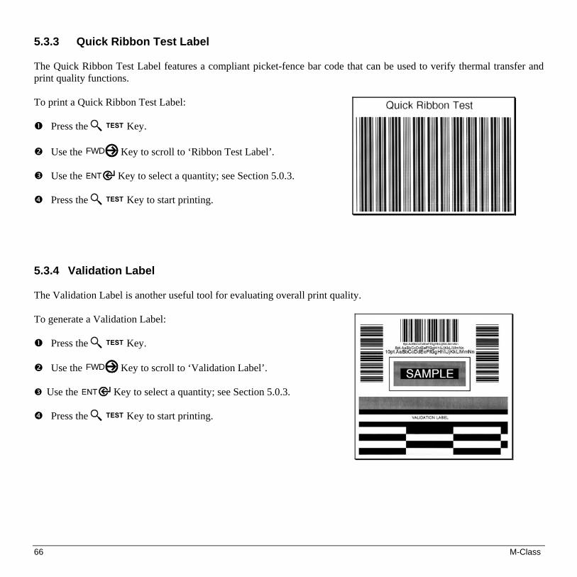
66 M-Class
5.3.3 Quick Ribbon Test Label The Quick Ribbon Test Label features a compliant picket-fence bar code that can be used to verify thermal transfer and print quality functions. To print a Quick Ribbon Test Label: Press the Key.
Use the FWD Key to scroll to ‘Ribbon Test Label’.
Use the Key to select a quantity; see Section 5.0.3.
Press the Key to start printing.
5.3.4 Validation Label The Validation Label is another useful tool for evaluating overall print quality. To generate a Validation Label: Press the Key.
Use the FWD Key to scroll to ‘Validation Label’.
Use the Key to select a quantity; see Section 5.0.3.
Press the Key to start printing.

M-Class 67
5.3.5 Print Last Label
Print Last Label reprints the last label format printed. The format can be any of the Test Labels, a label from the host, or one recalled from memory.
Note: If a job was cancelled prior to its completion, or if power has been removed since the last print job and the request for this label, this selection will print a ‘VOID’ message.
5.3.6 User Defined Label
The User Defined Label reprints from a list of previously printed label formats. Use the FWD Key to scroll through the listing, then use the Key to select and print the label.
Note: If a job was cancelled prior to its completion or if power has been removed since the last print job and the request for this label, ‘NO FILES AVAILABLE’ will be displayed and no printing will occur.

68 M-Class
5.4 Media Sensor Calibration In addition to the Sensor Type selection, Media Sensor calibration ensures that each label is detected correctly and reliably. Perform calibration when the ‘Uncalibrated’ message is displayed. Three different methods are available to calibrate the printer: Quick, Standard, and Advanced Entry.
5.4.1 Quick Calibration At the factory, the printer is calibrated to sense a wide range of media types. Quick Media Calibration fine-tunes the media sensor for your gap, notch or reflective media application, and is not required if you are using continuous media. Perform this calibration during initial set-up or after changing your media type.
Notes: If ‘Uncalibrated’ is displayed, follow the Media Sensor Calibration procedure in Section 5.4.2. Also, media containing large gaps may first require a change in the ‘Paper Out Distance’ setting; see Section 5.1.2.
To calibrate: Ensure that media is loaded (see Section 3.2), that the Media Sensor is adjusted (see Section 3.3), and that the printer
is idle. Press and hold the Key. The printer will begin advancing media; allow at least one label gap (or mark) to
advance under the sensor before releasing the button. Upon successful completion, the ‘Calibration Completed’ message will flash; the printer will feed to the next label TOF and ‘Ready’ will be displayed. (A ‘Warning Low Backing’ message may appear if using notched media or media on a transparent liner; however, the calibration was successful). Calibration Hint: In certain cases, the printer may have trouble differentiating between the label and liner. If the printer stops feeding in the middle of a label or if ‘Cannot Calibrate’ is displayed, try calibrating over a longer distance: • Press and hold the Key to allow two or more gaps (or marks) to advance under the sensor. If this fails, see
Standard Calibration (Section 5.4.2).

M-Class 69
5.4.2 Standard Calibration
Standard Calibration is appropriate for most media types. During the process, the printhead assembly can be raised for visual access to the media and media sensor. In addition, displayed sensor readings can be used to indicate the best position over the media, which is helpful when using small, position-critical TOF notches or marks. Three readings are required:
Empty: No media in the sensor. Gap (or Mark): Only the backing, notch, or reflective mark in the sensor. Paper: The label (with the liner attached) in the sensor.
To perform a Standard Calibration:
Step Operator Action Displayed Message Comment
1
(Media should be loaded and the appropriate Sensor Type selected.)
Turn ‘On’ the printer.
!
!!VODBMJCSBUFE!
!
Wait until the printer initializes (about six seconds).
2
Press the MENU Key.
Raise the printhead assembly.
!
NFOV!NPEF!NFEJB!TFUUJOHT!
!!!!
You are entering Menu Mode.
3
Press the Key to enter the Media Settings menu.
!
NFEJB!TFUUJOHT!NFEJB!UZQF!
!!!!
See Section 5.1.2 for menu layout.
4
Press the FWD Key and scroll to ‘Sensor Calibration’.
!
NFEJB!TFUUJOHT!TFOTPS!DBMJCSBUJPO!
!!!
Press the Key to abort this procedure.
5
Press the Key.
!
TFOTPS!DBMJCSBUJPO!QFSGPSN!DBMJCSBUJPO!
!
You are beginning the standard calibration procedure.
6
Press the Key.
Remove the media from the Media Sensor then the key.
!!
SFNPWF!MBCFM!TUPDL!QSFTT!FTD!LFZ!=zzz?!
!
This sets the parameter for the ‘empty’ value. Where ‘yyy’ is a numerical value representing the current sensor reading.

70 M-Class
Standard Calibration (continued)
Step Operator Action Displayed Message Comment
7
Proceed according to your media type: Die-cut stock: strip the media from the backing and then reinsert it into the sensor; adjust the Sensor Eye Mark over the center of the backing. Notched stock: adjust the Sensor Eye Mark over the center of the notch. Reflective stock: Adjust the Sensor Eye Mark over the center of the facedown black mark. Continuous stock: go to Step 8.
Press the key to continue.
TDBO!CBDLJOH!QSFTT!FTD!LFZ!!!=zzz?!
!
Or, for reflective media: !
TDBO!NBSL!QSFTT!FTD!LFZ!!!=zzz?!
This sets the parameter for the ‘gap’ or ‘mark’ value.
Where ‘yyy’ is a numerical value representing the current sensor reading: useful in locating the best sensor position.
Note: Never position the sensor over a perforation
when recording a sensor reading.
Note: Do NOT move the position of the Media Sensor after it has been adjusted.
8
Position the label (and backing, if any) under the Sensor Eye Mark.
Note: If using preprinted media, ensure the label area under the sensor is free of preprinted text, graphics or borders.
Press the key to continue.
!
TDBO!QBQFS!QSFTT!FTD!LFZ!!=zzz?!
!!
This sets the parameter for the ‘paper’ value.
Where ‘yyy’ is a numerical value representing the current sensor reading.
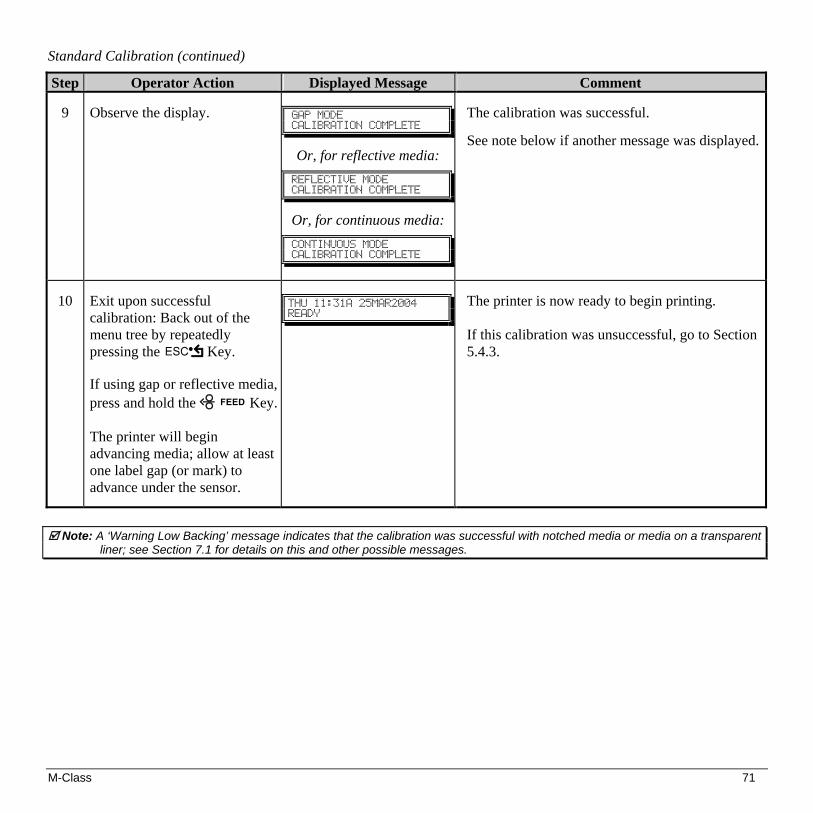
M-Class 71
Standard Calibration (continued)
Step Operator Action Displayed Message Comment
9
Observe the display.
!
HBQ!NPEF!DBMJCSBUJPO!DPNQMFUF!
!!
Or, for reflective media: !
SFGMFDUJWF!NPEF!!DBMJCSBUJPO!DPNQMFUF!
!!
Or, for continuous media: !!
DPOUJOVPVT!NPEF!!DBMJCSBUJPO!DPNQMFUF!
The calibration was successful.
See note below if another message was displayed.
10
Exit upon successful calibration: Back out of the menu tree by repeatedly pressing the Key.
If using gap or reflective media, press and hold the Key. The printer will begin advancing media; allow at least one label gap (or mark) to advance under the sensor.
!
UIV!22;42B!36NBS3115!!SFBEZ!
!
The printer is now ready to begin printing. If this calibration was unsuccessful, go to Section 5.4.3.
Note: A ‘Warning Low Backing’ message indicates that the calibration was successful with notched media or media on a transparent
liner; see Section 7.1 for details on this and other possible messages.

72 M-Class
5.4.3 Advanced Entry Calibration
Note: Advanced Entry Calibration will override all previous calibration settings; this method should be used only when Standard Calibration has failed.
Advanced Entry Calibration is the alternate method for special-case media types. The procedure has two parts:
1) You must list the sensor readings for the label and TOF values using different algorithms.
2) From your list the best algorithm is chosen, new readings taken and those values entered. To perform an Advanced Entry Calibration:
Step Operator Action Displayed Message Comment
1
(Media should be loaded and the appropriate Sensor Type selected.) Turn ‘On’ the printer.
!
!!VODBMJCSBUFE!
!
Wait until the printer initializes (about six seconds).
2
Press the MENU Key. Raise the printhead assembly.
!
NFOV!NPEF!NFEJB!TFUUJOHT!
!!!!
You are entering Menu Mode.
3 Press the Key to enter the Media Settings menu.
!
NFEJB!TFUUJOHT!NFEJB!UZQF!
!!!!
See Section 5.1.2 for menu layout.
4 Press the FWD Key and scroll to ‘Sensor Calibration’.
!
NFEJB!TFUUJOHT!TFOTPS!DBMJCSBUJPO!
!!!
Press the Key to abort this procedure.
5
Press the Key.
!
TFOTPS!DBMJCSBUJPO!QFSGPSN!DBMJCSBUJPO!
!
You are entering the calibration submenu.
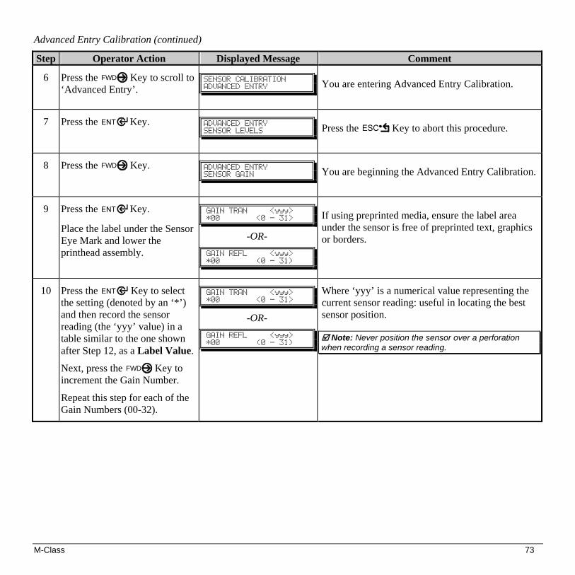
M-Class 73
Advanced Entry Calibration (continued)
Step Operator Action Displayed Message Comment
6
Press the FWD Key to scroll to ‘Advanced Entry’.
!
TFOTPS!DBMJCSBUJPO!BEWBODFE!FOUSZ!
!
You are entering Advanced Entry Calibration.
7
Press the Key. !
BEWBODFE!FOUSZ!TFOTPS!MFWFMT!
!!
Press the Key to abort this procedure.
8
Press the FWD Key. !
BEWBODFE!FOUSZ!TFOTPS!HBJO!
!!
You are beginning the Advanced Entry Calibration.
9
Press the Key.
Place the label under the Sensor Eye Mark and lower the printhead assembly.
!
HBJO!USBO!!!!!=zzz?!+11!!!!!!!!=1!.!42?!!
-OR-
HBJO!SFGM!!!!!=zzz?!+11!!!!!!!!)1!.!42*!
If using preprinted media, ensure the label area under the sensor is free of preprinted text, graphics or borders.
10
Press the Key to select the setting (denoted by an ‘*’) and then record the sensor reading (the ‘yyy’ value) in a table similar to the one shown after Step 12, as a Label Value.
Next, press the FWD Key to increment the Gain Number.
Repeat this step for each of the Gain Numbers (00-32).
!
HBJO!USBO!!!!!=zzz?!+11!!!!!!!!=1!.!42?!!
-OR-
HBJO!SFGM!!!!!=zzz?!+11!!!!!!!!)1!.!42*!
Where ‘yyy’ is a numerical value representing the current sensor reading: useful in locating the best sensor position.
Note: Never position the sensor over a perforation
when recording a sensor reading.
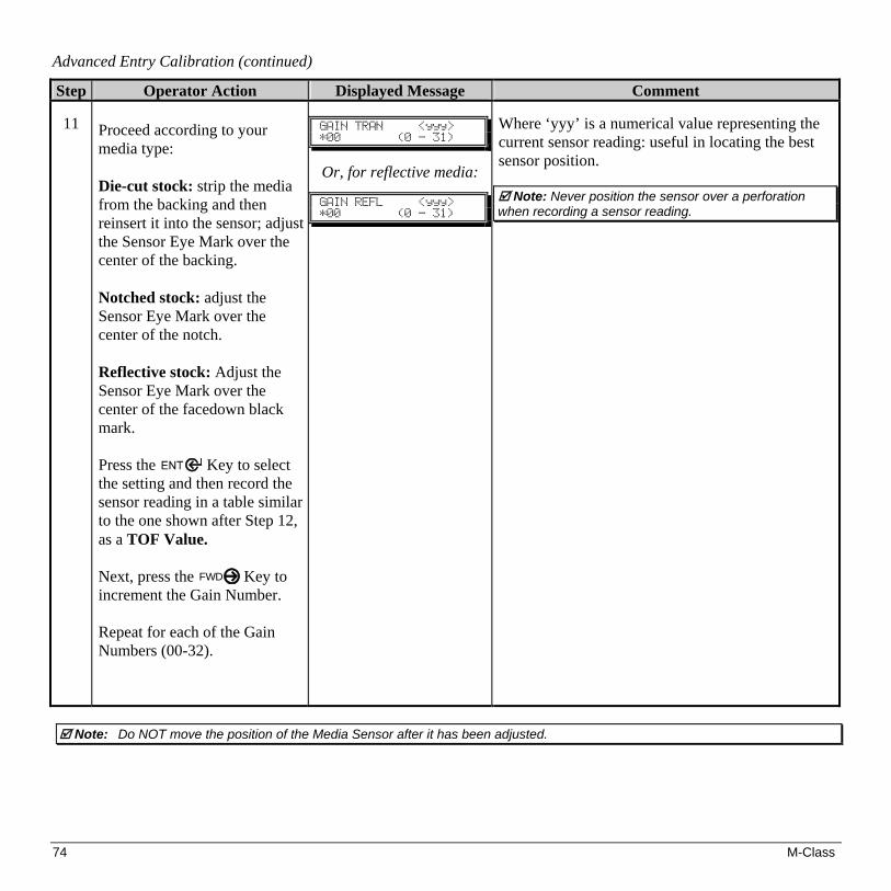
74 M-Class
Advanced Entry Calibration (continued)
Step Operator Action Displayed Message Comment
11 Proceed according to your media type: Die-cut stock: strip the media from the backing and then reinsert it into the sensor; adjust the Sensor Eye Mark over the center of the backing. Notched stock: adjust the Sensor Eye Mark over the center of the notch. Reflective stock: Adjust the Sensor Eye Mark over the center of the facedown black mark. Press the Key to select the setting and then record the sensor reading in a table similar to the one shown after Step 12, as a TOF Value. Next, press the FWD Key to increment the Gain Number. Repeat for each of the Gain Numbers (00-32).
!
HBJO!USBO!!!!!=zzz?!+11!!!!!!!!)1!.!42*!
!
Or, for reflective media:
HBJO!SFGM!!!!!=zzz?!+11!!!!!!!!)1!.!42*!
Where ‘yyy’ is a numerical value representing the current sensor reading: useful in locating the best sensor position.
Note: Never position the sensor over a perforation
when recording a sensor reading.
Note: Do NOT move the position of the Media Sensor after it has been adjusted.

M-Class 75
Advanced Entry Calibration (continued)
Step Operator Action Displayed Message Comment
12
From the data collected in Steps 10 and 11, where both the sensor readings are above 20, subtract each Label Value from the corresponding TOF Value. These are the Difference Values.
From the resulting list, find the largest Difference Value (see example below). Its associated Gain Number will provide the best algorithm for your media.
!
HBJO!USBO!!!!!!=zzz?+11!!!!!!!!!)1!.!42*!
!
Or, for reflective media:
HBJO!SFGM!!!!!!=zzz?+11!!!!!!!!!)1!.!42*!
Both sensor readings must be above 20.
Gain Number
Label Value
TOF Value
Difference Value
00 255 254 1 01 251 240 11 02 241 213 28 03 231 182 49 04 219 150 69 05 212 119 93 06 200 88 112 07 189 58 131 08 178 32 146 09 167 19 N/A 10 156 17 N/A 11 146 16 N/A 12 136 15 N/A … … … … 31 116 14 N/A
For example, if your compiled data had the values shown in this table, Gain Number 8 would be chosen because it has the highest Difference Value (146) where both the Label Value and the TOF Value are above 20.
32 112 14 N/A

76 M-Class
Advanced Entry Calibration (continued)
Step Operator Action Displayed Message Comment
13
Using the FWD Key, select the Gain Number determined in Step 12. Press the Key to select the setting.
!
HBJO!USBO!!!!!!=zzz?+19!!!!!!!!!)1!.!42*!
!
Or, for reflective media:
HBJO!SFGM!!!!!!=zzz?+19!!!!!!!!!)1!.!42*!
Selection is denoted with an ‘*’.
14
Place the media in the Media Sensor. Record the sensor reading and label it ‘P’ (paper).
Place the backing, mark, or notch in the Media Sensor. Record the sensor reading and label it ‘G’ or ‘M’ (Gap or Mark).
Remove all media. Record the sensor reading and label it ‘E’ (Empty).
!
HBJO!USBO!!!!!!=zzz?+19!!!!!!!!!)1!.!42*!
!
Or, for reflective media:
HBJO!SFGM!!!!!!=zzz?+19!!!!!!!!!)1!.!42*!
Where ‘yyy’ is a numerical value representing the current sensor reading.
15
Press the Key. Then press the FWD Key.
!
BEWBODFE!FOUSZ!TFOTPS!MFWFMT!
!
The sensor readings must be manually entered into the printer now.
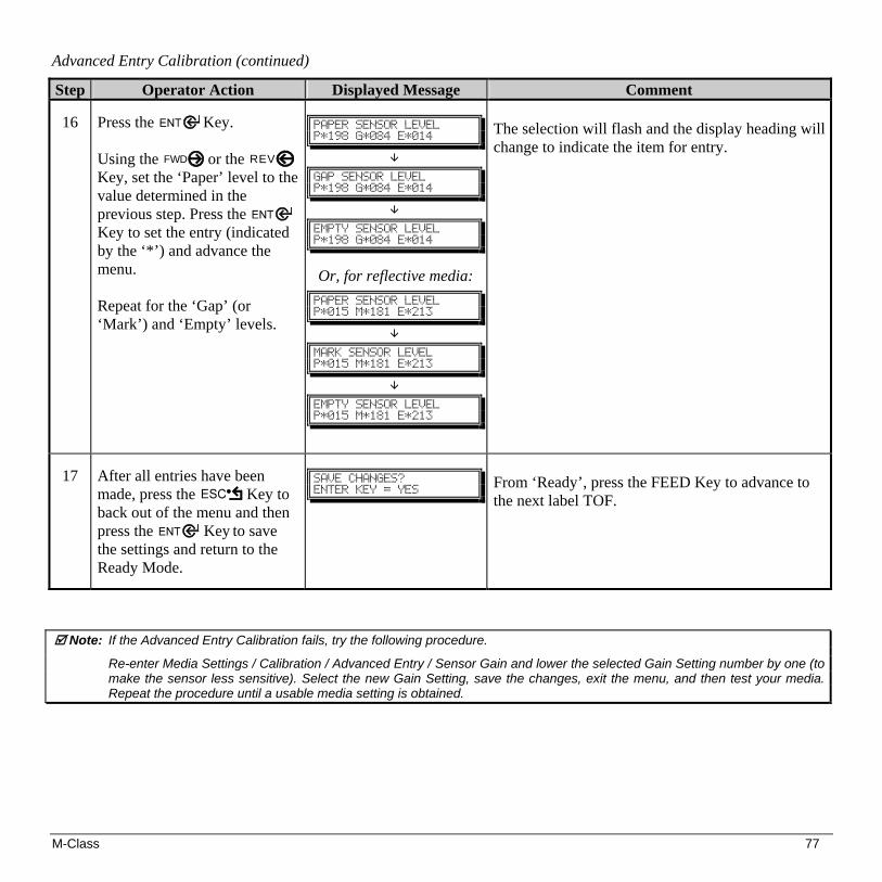
M-Class 77
Advanced Entry Calibration (continued)
Step Operator Action Displayed Message Comment
16
Press the Key. Using the FWD or the REV Key, set the ‘Paper’ level to the value determined in the previous step. Press the Key to set the entry (indicated by the ‘*’) and advance the menu. Repeat for the ‘Gap’ (or ‘Mark’) and ‘Empty’ levels.
!
QBQFS!TFOTPS!MFWFM!Q+2:9!H+195!F+125!
!
!
HBQ!TFOTPS!MFWFM!Q+2:9!H+195!F+125!
!
!
FNQUZ!TFOTPS!MFWFM!Q+2:9!H+195!F+125!
!!!!
Or, for reflective media: !
QBQFS!TFOTPS!MFWFM!Q+126!N+292!F+324!
!
!
NBSL!TFOTPS!MFWFM!Q+126!N+292!F+324!
!
!
FNQUZ!TFOTPS!MFWFM!Q+126!N+292!F+324!
The selection will flash and the display heading will change to indicate the item for entry.
17
After all entries have been made, press the Key to back out of the menu and then press the Key to save the settings and return to the Ready Mode.
!
TBWF!DIBOHFT@!FOUFS!LFZ!>!ZFT!
!!!
From ‘Ready’, press the FEED Key to advance to the next label TOF.
Note: If the Advanced Entry Calibration fails, try the following procedure.
Re-enter Media Settings / Calibration / Advanced Entry / Sensor Gain and lower the selected Gain Setting number by one (to make the sensor less sensitive). Select the new Gain Setting, save the changes, exit the menu, and then test your media. Repeat the procedure until a usable media setting is obtained.

78 M-Class

M-Class 79
6.0 Introduction
This Section details the cleaning, adjusting, and troubleshooting tips for the printer. The following table outlines the recommended maintenance schedule for the various printer parts.
Area Method Interval Printhead Turn off the printer before cleaning the
printhead. Use solvent* on a cotton swab to clean the printhead from end to end.
After every roll of media.
Platen Roller Turn the power off. Rotate the platen roller and clean it thoroughly with solvent* and a cotton swab.
After every roll of media.
Peel-Off Roller Rotate the peel-off roller and clean it thoroughly with solvent* and a cotton swab.
After every roll of media.
Media Path
Solvent* After every roll of media.
Peel/Tear Bar
Solvent* As needed
Media Sensor
Air blow Monthly
Exterior
Mild detergent or desktop cleaner. As needed
Interior
Brush or vacuum cleaner As needed.
* It is recommended that a solvent containing isopropyl alcohol be used.
WARNING
Isopropyl alcohol is a flammable solvent; always take the proper precautions when using this substance.

80 M-Class
6.1 Cleaning the Printhead
If print quality declines (symptoms include non-compliant bar codes, print dropouts, and streaks; see sample label below), the typical cause is debris build-up on the printhead. Furthermore, when the build-up is not removed it may lead to element failure, greatly reducing the service life of the printhead.
Faulty Print Quality Label: Streaks indicate a dirty or faulty printhead.
To clean the printhead: 1. Turn ‘Off’ and unplug the printer. 2. Open the cover. Unlock the Printhead Latch and
raise the Printhead Assembly. Allow the printhead to cool before proceeding.
3. Move media and ribbon away from the printhead as
necessary. 4. Using a Cotton Swab moistened, not soaked, with
isopropyl alcohol gently wipe away any build-up on the printhead surface, paying close attention to the Burn Line. Allow the printhead to dry.
5. Replace the ribbon and media. Lower the Printhead
Assembly back to the locked position. 6. Close the cover. Plug in and turn ‘On’ the printer.
Feed several labels to normalize tracking.

M-Class 81
6.1.1 Automated Printhead Cleaning (printers with display, only) 1. Remove media and ribbon. 2. Place a Datamax Cleaning Card, part number 70-2013-01 under the printhead. Lower and lock the printhead. Ensure
that the Leveling Cam is not engaged (positioned in its left most position). 3. Press and hold the TEST Key for approximately four seconds.
The printer will begin the cleaning routine. 4. In cases of heavy build-up, or if high heat values are typically used for printing, flip the card over and repeat Step 3. 5. Reinstall your ribbon and media (if necessary, readjust the Leveling Cam, see Section 6.2). Lower and lock the
printhead. Close the cover.
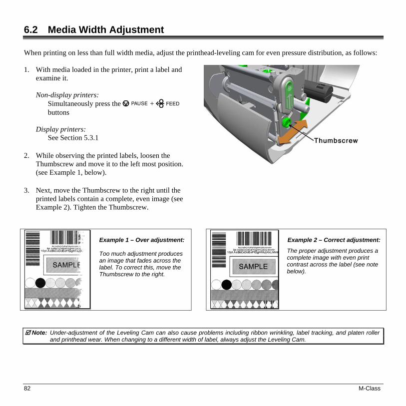
82 M-Class
6.2 Media Width Adjustment When printing on less than full width media, adjust the printhead-leveling cam for even pressure distribution, as follows: 1. With media loaded in the printer, print a label and
examine it.
Non-display printers: Simultaneously press the PAUSE + FEED buttons
Display printers: See Section 5.3.1
2. While observing the printed labels, loosen the Thumbscrew and move it to the left most position. (see Example 1, below).
3. Next, move the Thumbscrew to the right until the printed labels contain a complete, even image (see Example 2). Tighten the Thumbscrew.
Example 1 – Over adjustment: Too much adjustment produces an image that fades across the label. To correct this, move the Thumbscrew to the right.
Example 2 – Correct adjustment:
The proper adjustment produces a complete image with even print contrast across the label (see note below).
Note: Under-adjustment of the Leveling Cam can also cause problems including ribbon wrinkling, label tracking, and platen roller and printhead wear. When changing to a different width of label, always adjust the Leveling Cam.

M-Class 83
6.3 Printhead Burn Line Adjustment The Burn Line has been adjusted for strict compliance using 6.5-mil (.0065 inch) media, ensuring print quality across a majority of media types. In extreme cases, however, if media of a different thickness or rigidity is used (for example, heavy tag stock), print quality can change.
Note: If you have questions, contact a qualified technician or Datamax Technical Support before proceeding.
To adjust the Burn Line: 1. Load the printer with your media (and ribbon, if required). 2. Loosen the two Locking Screws approximately ¼ turn counter-
clockwise. 3. Turn the Adjustment Screws counter-clockwise until the burn line is
past the platen roller vertex. Print a test label; the label should look light and uneven.
Non-display printers:
Simultaneously press the PAUSE + FEED buttons
Display printers: See Section 5.3.1
4. Tighten the Locking Screws just until they are ‘snug’ (tight enough to remove any play in the printhead assembly, yet loose enough to allow the Adjustment Screws to move the printhead).
5. Turn each Adjustment Screw clockwise about a ¼ turn (or an 1/8 turn for finer adjustments, see note below). Print
another test label and examine the print quality. Repeat this step until labels are produced with even print contrast and acceptable print quality.
Note: When the Locking Screws are ‘snug’, turning the Adjustment Screws counter-clockwise will NOT move the printhead
outward; if you have adjusted the printhead too far inward, restart the entire procedure. 6. Tighten the Locking Screws then print a final test label to verify the adjustment.

84 M-Class
6.4 Printhead Pressure Adjustment To accommodate a variety of media types, printhead pressure is adjustable. This pressure is factory set to work with most media types, so this adjustment should only be performed after attempting to improve print quality through the use of the (1) heat and/or (2) print speed. When adjusting, use only the minimum pressure necessary for better imaging. To adjust:
1. Load at least 4” (102mm) wide media and ribbon, see Section 3.2. 2. Ensure the Media Width Adjustment is set to its “left most” position, see Section 6.2. 3. Print a test label.
Non-display printers:
Simultaneously press the PAUSE + FEED buttons Display printers:
See Section 5.3.1 4. Turn the Printhead Pressure Adjustment Screws counterclockwise to increase the applied pressure or clockwise to
decrease it. Make equal adjustments to each screw to achieve even print contrast across the media.
Notes: When using narrow media it is sometimes necessary to increase the pressure on the inner (closest to centerplate) Printhead Pressure Adjustment Screw to prevent ribbon smudging.
Excessive pressure can reduce the service life of the printhead and platen roller, while unequal pressure may cause ribbon and label tracking problems.

M-Class 85
6.5 Printhead Replacement To replace a damaged printhead, follow the procedure below.
Note: Printheads are fragile; use extreme care when handling and never use a sharp object on the surface. If you have questions, contact a qualified technician or Datamax Technical Support before proceeding.
1. Touch a bare metal part of the printer’s frame to discharge any
static electricity that may be present on your body. 2. Turn ‘Off’ and unplug the printer. Open the cover; if ribbon is
installed, remove it. 3. With the printhead locked in the down position, loosen the
Printhead Mounting Screw (it will remain in the assembly). 4. Unlatch the Printhead Assembly. While holding the Printhead,
raise the assembly. Disconnect the two cables and then remove the old Printhead.
5. While carefully holding the new Printhead, connect both cables. 6. Position the Printhead onto the Locating Pins in the Printhead
Assembly and secure in place with the Printhead Mounting Screw (do not over-tighten).
7. Clean the Printhead (see Section 6.1). 8. Reload ribbon (if removed), lower the printhead assembly, and rotate the printhead latch back, into the locked
position. 9. Use the Darkness Adjustment to match the print contrast of the new printhead to that of the old printhead (for non-
display printers see Section 6.6 for display printers see Section 5.1.3).

86 M-Class
6.6 Darkness Adjustment
Non-display printers: The Darkness Adjustment allows the operator to match the print contrast following a printhead replacement. Turning the Darkness Adjustment clockwise will darken the print, while turning it counterclockwise will lighten the print. Compare a label printed with the old printhead and make this adjustment so that the new printhead matches the darkest portion of that label. Display-equipped printers: Use the menu to adjust Darkness; see Section 5.1.3, Print Control / Custom Adjustments.
Note: Large increases in the ‘Darkness Adjustment’ can shorten printhead life. If you need to increase the darkness of the printed labels, try increasing the Heat value and/or slow the Print Speed using your software program or via DPL commands.
6.7 Resetting the Printer Non-Display Printers: With the printer power ‘Off,’ press and hold all three buttons while turning ‘On’ the printer. Continue to hold the buttons down until the STOP light turns off (approximately 17 seconds). The printer will now be set to the ‘Factory Defaults.’ See Section 4.5.1 for a listing of the factory default settings. Display Printers: Depending upon the method used, there are three reset levels possible: Soft Reset To reset the printer and clear any temporary host settings: With the printer ‘On’, press and hold the CANCEL Key for approximately four seconds.

M-Class 87
Level One Reset To return the printer to the factory default settings or, if saved, to restore the Factory Setting File: Turn ‘Off’ the printer.
Press and hold the PAUSE and CANCEL Keys while turning ‘On’ the printer; continue to depress the keys until the
‘READY’ message appears.
Note: This reset has the same effect as the System Settings / Set Factory Defaults selection in the menu system. (See Section 5.1 for a listing of the factory default settings and Section 5.1.5 for information about the Factory Setting File.)
Level Two Reset To return the printer to the factory default settings, and clear all the calibration and adjustment parameters: Turn ‘Off’ the printer.
Press and hold the PAUSE, FEED, and CANCEL Keys while turning ‘On’ the printer; continue to depress the keys
until the ‘READY’ message appears.
Note: After executing a Level 2 Reset, the media calibration must be performed; see Section 5.4. A listing of the factory default settings can be found in Section 5.1.
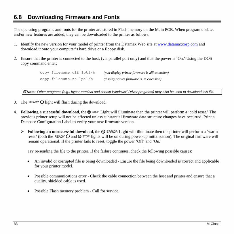
88 M-Class
6.8 Downloading Firmware and Fonts The operating programs and fonts for the printer are stored in Flash memory on the Main PCB. When program updates and/or new features are added, they can be downloaded to the printer as follows: 1. Identify the new version for your model of printer from the Datamax Web site at www.datamaxcorp.com and
download it onto your computer’s hard drive or a floppy disk.
2. Ensure that the printer is connected to the host, (via parallel port only) and that the power is ‘On.’ Using the DOS copy command enter:
copy filename.dlf lpt1/b (non-display printer firmware is .dlf extension)
copy filename.zs lpt1/b (display printer firmware is .zs extension)
Note: Other programs (e.g., hyper-terminal and certain Windows® Driver programs) may also be used to download this file.
3. The READY light will flash during the download. 4. Following a successful download, the STOP Light will illuminate then the printer will perform a ‘cold reset.’ The
previous printer setup will not be affected unless substantial firmware data structure changes have occurred. Print a Database Configuration Label to verify your new firmware version. Following an unsuccessful download, the ERROR Light will illuminate then the printer will perform a ‘warm
reset’ (both the READY and STOP lights will be on during power-up initialization). The original firmware will remain operational. If the printer fails to reset, toggle the power ‘Off’ and ‘On.’
Try re-sending the file to the printer. If the failure continues, check the following possible causes: • An invalid or corrupted file is being downloaded - Ensure the file being downloaded is correct and applicable
for your printer model. • Possible communications error - Check the cable connection between the host and printer and ensure that a
quality, shielded cable is used. • Possible Flash memory problem - Call for service.

M-Class 89
7.0 Problem Resolution Should a problem arise, the information in this section will help you resolve it. The following table lists problems that may not necessarily generate an error condition. Items denoted with an asterisk (*) are only for printers with displays.
Note: If you have questions, contact a qualified technician or Datamax Technical Support.
If experiencing this problem… Try this solution…
Can not communicate through the parallel port:
Observe the Ready Indicator as the format is sent to the printer. If it does not flash, check the parallel cable type. Also, check the protocol and port settings between the printer and host.
Can not load media through the optional cutter:
WARNING! Use extreme care. Turn ‘Off’ and unplug the printer before proceeding.
Ensure that the cutter is properly installed. Plug in and turn ‘On’ the printer. You should hear the cutter blade rotate and position itself properly. However, if the problem continues call for service.
* The LCD is blank, but the Ready Indicator is ‘On’:
The display contrast may set too low. Press and hold the MENU Key for 10 seconds or until the display reappears.
Erratic feeding:
The printer may require Calibration;
Printers without front display: Perform calibration, see section 4.7.1.
Printers with front display: Press and hold the FEED button until at least one label gap or mark is advanced.
Erratic printing (instead of the label format, strange characters are printed):
• The printer may be in Hex Dump Mode; see Section 7.2.
• If using the serial port for communicating, check both the host and printer port settings; the printer may be set to eight data bits while the host is set to 7 (or vice versa).

90 M-Class
If experiencing this problem… Try this solution…
Intellifont™ will not print: Intellifont™ format is Little/Big Endian specific. The printer uses Big Endian. Refer to your font supplier for information.
Light print on the right side (facing the printer) of the label:
• The Printhead Leveling Cam may be incorrectly adjusted; see Section 6.2.
• The Printhead or Platen Roller may be dirty or worn; clean or call for service.
Missing information in the printed label:
• Check the label format for character placement outside the dimensions of the label; all row/column values must allow enough space for the height/length of the characters and bar codes to be printed within the format size.
• The available memory may have been exceeded by the memory requirement of the label format. Try reducing the memory allocated to either the internal module or scaleable font caches; non-display printers see Section 4.5.2, display printers see Section 5.1.5
• If using serial communications, ensure that the interface cable meets the requirements found in Section 3.1.2.
Missing print on left or right side of the label:
Information may be formatted outside the label dimensions. Check your software program label size. For display printers also check the values in the menu for Print Control / Column Offset and Print Control / Custom Adjustments / Column Offset; see Section 5.1.3.
No power (all indicator lights are ‘Off”):
• Verify that the AC power cord connection has been made at both the outlet and the printer; also, ensure the power switch is ‘On’.
• Verify that the AC outlet is functioning, or try moving the printer to another AC circuit.
• The AC cord may be damaged; replace it.
• The line fuse may be blown; call for service.

M-Class 91
If experiencing this problem… Try this solution…
Nothing is printing (labels advance normally, but no image is printed):
Examine the used ribbon for an image:
If there is an image on the used ribbon: Verify that the ribbon was properly loaded per Section 3.4.
If properly loaded, the wrong coating configuration was used. (To verify the inked side, press the adhesive backing of a label against the ribbon surface. Ink will only lift from the coated side of the ribbon.) Clean the printhead (see Section 6.1); then replace the ribbon with the correct type for the printer, Section 3.4.
If there is no image on the used ribbon: • Print any Internal Test Label; non-display printers see Section 4.8, display
printers see Section 5.3. If an image printed, then check the protocol and port settings for both the printer and host. These must match.
• The heat setting may be too low. Make an adjustment in the software program or through the Front Panel.
• The media/ribbon combination may be incorrect. Contact a Media Representative.
• The printhead or printhead cable(s) may be loose; power ‘Off’ the printer then reconnect.
Nothing happens when trying to print using a software program:
• Ensure that the printer is at READY.
• Observe the Front Panel, if the READY light does not flash as you send the format check the protocol and port settings between the printer and host.
• Ensure the interface cable meets the requirements found in Section 3.1.2.

92 M-Class
If experiencing this problem… Try this solution…
Poor print quality:
• The printhead may need cleaning; see Section 6.1.
• Adjust the Heat and Print Speed settings through the Front Panel or by host commands; non-display printers see Section 4.5.2, display printers see Section 5.1.3.
• The media/ribbon combination may not be compatible; contact a Media Representative.
• The Printhead Leveling Cam may be incorrectly adjusted; see Section 6.2.
• The Platen Roller may be dirty or worn; clean or call for service.
• The Printhead Burn Line may need adjusting; see Section 6.3.
Skips labels when printing:
• Media Calibration may be needed; non-display printers see Section 4.7, display printers see Section 5.4.
• The Media Sensor may be out of position; readjust the position; see Section 3.3.
• The format may be within 1/8 inch of the label’s trailing edge. Try reducing or moving the format slightly.
Unable to print rotated text: The characters may be formatted outside the label dimensions. Ensure the row/column values provide enough room for the height of the characters or bar code to be printed. See the Class Series Programmer’s Manual for details.

M-Class 93
7.1 Fault and Warning Messages (Display Printers Only) All printer functions are internally monitored. If a problem (Fault) or a potential problem (Warning) is detected, the Error Indicator will be illuminated. A corresponding message will be displayed. These messages, along with possible solutions, are described below. Fault Messages: Fault Messages receive the highest display priority. If more than one fault is detected, the display will
toggle between messages.
Note: To return to normal operation after the printer enters a fault condition, the fault must be corrected and then the FEED Key must be pressed to clear the condition.
Printer Fault Messages
Displayed Message Description Possible Solution(s) !
!35W!PVU!PG!UPMFSBODF!
!
The printer has detected a drop in the 24-volt power supply.
Try cycling the printer power ‘Off’ and ‘On’. If the fault does not clear, call for service.
!
!BED!GBVMU!
!
The printer has detected an analog to digital circuit converter failure.
Try cycling the printer power ‘Off’ and ‘On’. If the fault does not clear, call for service.
!
!DVUUFS!GBVMU!
!
The printer has detected a cutter mechanism fault.
WARNING! Use extreme care. Turn ‘Off’ and unplug the printer before proceeding.
Examine the cutter for obstructions and ensure that the cutter cable is properly installed. Plug in and turn ‘On’ the printer. Press the FEED Key. If the fault does not clear, call for service.
!
!ENB!GBVMU!
The printer has detected a Direct Memory Access failure.
Try cycling the printer power ‘Off’ and ‘On’. If the fault does not clear, call for service.
!
HBQ!NPEF!DBOOPU!DBMJCSBUF!
!
Consistently low sensor readings were detected.
Press any key to continue. Ensure that media was inserted in the media sensor during the appropriate calibration step; also ensure that the sensor is free of debris. Retry the calibration. If the problem persists, try the ‘Advanced Entry Calibration’; see Section 5.4.3.
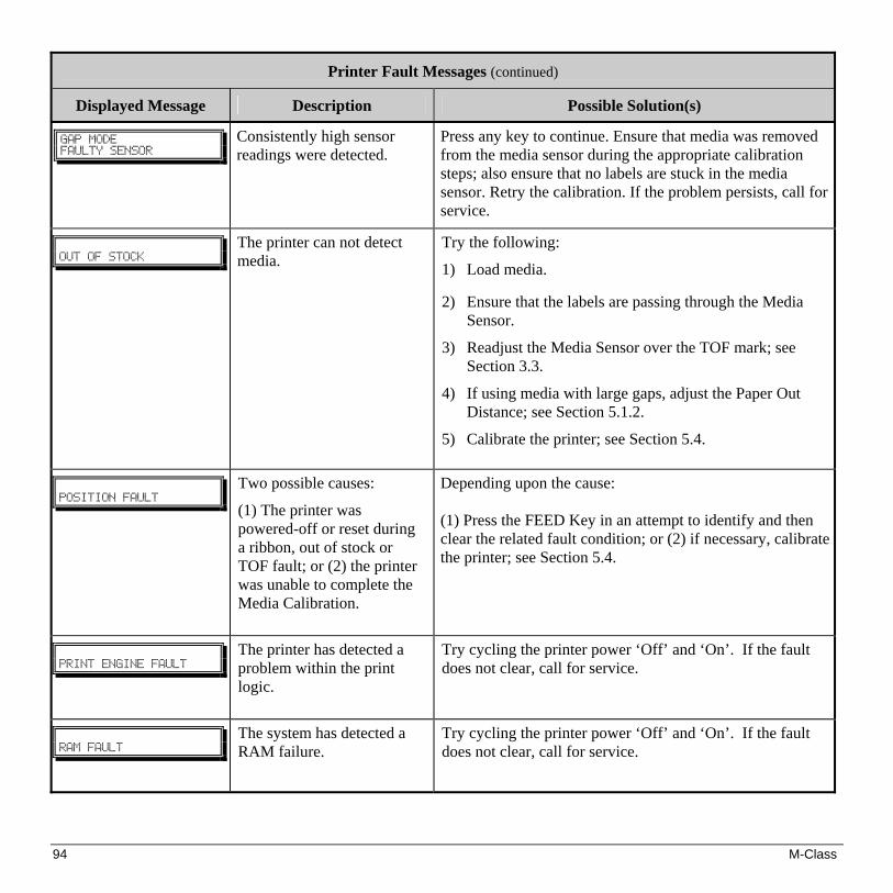
94 M-Class
Printer Fault Messages (continued)
Displayed Message Description Possible Solution(s) !
HBQ!NPEF!GBVMUZ!TFOTPS!
!
Consistently high sensor readings were detected.
Press any key to continue. Ensure that media was removed from the media sensor during the appropriate calibration steps; also ensure that no labels are stuck in the media sensor. Retry the calibration. If the problem persists, call for service.
!
!PVU!PG!TUPDL!
!
The printer can not detect media.
Try the following:
1) Load media. 2) Ensure that the labels are passing through the Media
Sensor.
3) Readjust the Media Sensor over the TOF mark; see Section 3.3.
4) If using media with large gaps, adjust the Paper Out Distance; see Section 5.1.2.
5) Calibrate the printer; see Section 5.4.
!
!QPTJUJPO!GBVMU!
Two possible causes:
(1) The printer was powered-off or reset during a ribbon, out of stock or TOF fault; or (2) the printer was unable to complete the Media Calibration.
Depending upon the cause: (1) Press the FEED Key in an attempt to identify and then clear the related fault condition; or (2) if necessary, calibrate the printer; see Section 5.4.
!
!QSJOU!FOHJOF!GBVMU!
The printer has detected a problem within the print logic.
Try cycling the printer power ‘Off’ and ‘On’. If the fault does not clear, call for service.
!
!SBN!GBVMU!
The system has detected a RAM failure.
Try cycling the printer power ‘Off’ and ‘On’. If the fault does not clear, call for service.

M-Class 95
Printer Fault Messages (continued)
Displayed Message Description Possible Solution(s) !
SFGMFDUJWF!NPEF!DBOOPU!DBMJCSBUF!
!
Consistently low sensor readings were detected.
Press any key to continue. Ensure that the reflective mark was inserted facedown in the media sensor during the appropriate calibration step; also, ensure that the reflective mark is made of carbon based ink, and that the sensor is free of debris. Retry calibration. If the problem persists, try an ‘Advanced Entry Calibration’; see Section 5.4.3.
!
SFGMFDUJWF!NPEF!GBVMUZ!TFOTPS!
!
Consistently high sensor readings were detected.
Press any key to continue. Ensure that media was removed from the media sensor during the appropriate calibration steps; also ensure that no labels are stuck in the media sensor. Retry the calibration. If the problem persists, call for service.
!
!SJCCPO!GBVMU!
!
The ribbon sensor values have changed, or the printer detects no or only sporadic ribbon supply hub movement.
Try the following:
1) Ensure that ribbon is correctly loaded and that the printhead assembly is latched.
2) Check the ribbon supply and ribbon take up hubs for obstructions that may be stopping movement.
3) Ensure that the ribbon core fits snugly on the ribbon supply hub.
4) Ensure that the media and paper combination is not slipping (usually caused by an incorrect match).
!
!UFNQFSBUVSF!GBVMU!
The printer has shutdown to allow the printhead temperature to cool.
Turn ‘Off’ the printer until cool to prevent permanent damage due to an excessive printhead temperature.

96 M-Class
Printer Fault Messages (continued)
Displayed Message Description Possible Solution(s) !
!UPQ!PG!GPSN!GBVMU!
!!
The printer could not find the TOF mark within the maximum label length setting or it found a TOF in an unexpected place.
Note: When the printer is set for reflective media, this fault is given for an out of stock condition.
If media is moving:
1) Press the FEED Key. It may be necessary to re-calibrate the printer; see Section 5.4.
2) The Media Sensor may be out of position. Readjust it; see Section 3.3.
3) The media may not be properly loaded. Reload media, also ensure that the Media Guide is positioned properly; see Section 3.2.
4) The Leveling Cam may be improperly adjusted; see Section 6.2.
5) The label may be longer than the default value for maximum length. Check the Media Settings / Maximum Label Length; see Section 5.1.2.
6) The Media Sensor may be obstructed. Check and carefully remove any obstruction (labels, paper dust, adhesive, etc).
If media is not moving:
The printhead assembly may not be latched; close it.

M-Class 97
Warning Messages:
Warning Messages are displayed for a period of five seconds. If multiple warnings are detected, the display will reflect the highest priority message.
Printer Warning Messages
Displayed Message Description Action(s) !
!EPU!GBJMVSF!
!
The printer has detected defective printhead elements.
Replace the printhead if the print quality becomes unacceptable.
!
HBQ!NPEF!XBSOJOH!MPX!CBDLJOH!
!
The printer measured only a small difference between the ‘empty’ and ‘gap’ sensor readings.
Transparent backing or notched media typically gives this indication. In this case, there may be a slight delay in the ‘Out of Stock’ indication, after the media supply is emptied; no action is required.
!
!HPPECZF!
!
Power has been removed and shutdown is in progress.
The printer power switch was turned ‘Off’, the line fuse has blown, or AC line voltage has been lost.
!
!IPTU!DIBOHFT!QFOEJOH!
!
The host has pending configuration changes that will not take effect until a ‘host reset command’ is issued.
To save changes, send a host reset command (in DPL); or to discard changes, perform a Soft Reset (see Section 6.7).
!
!MPX!WPMUBHF!
The printer has detected a low operating voltage.
Possible low or fluctuating line voltage level. Try moving the printer to another outlet. When more than 50% black is being printed, try reducing the Heat Value or the size of the black image. If the condition persists, call for service.
!
!SUD!SBN!GBJMVSF!
!
The printer was unable to save settings in permanent memory.
Possible faulty Main PCB. If the condition persists, call for service.
!
!JQ!EJTDPWFS!GBJMFE!
!
The printer was unable to find a DHCP server.
This message does not effect the operation of the printer and can be cleared from the display by pressing the FEED button. To stop this from reoccurring be sure the menu item ‘IP DISCOVERY’ is set to ‘DISABLED’, see Section 5.1.6.
!
!UFNQFSBUVSF!QBVTF!
A high printhead temperature has been detected.
No action required. Printing will resume after the printhead cools.

98 M-Class
7.2 Hex Dump Mode
The Hex Dump Mode is a useful tool for diagnosing problems, including communication and DPL™ syntax errors, allowing a comparison of input strings (sent by host) to output data (received by printer). To decode this information, the Class Series Programmer’s Manual is an essential reference. This output can be used for debugging the label format. In addition, by repeatedly sending a format, this mode can uncover handshaking problems (if they exist). Handshaking problems are identified by sections of missing data in the character string.
To print the Hex Dump Label:
Non-display printers: With the printer on, loaded with media (at least 4 inches wide) and ribbon (if printing with thermal transfer media), press and hold the FEED button while turning the printer on. Continue holding the FEED button until the STOP light turns off. Now, all data received by the printer will be output in hexadecimal code, along with the printable ASCII equivalents, as shown below. To exit Hex Dump Mode, simply turn the printer off and then back on. Display printers: To begin, go to the Diagnostics menu and enable Hex Dump Mode; see Section 5.1.7. Exit the menu and save the changes. Now, ‘HEX DUMP MODE’ will be indicated by the display and all data sent to the printer will now be output in hexadecimal code, along with the printable ASCII equivalents, as shown below. To exit Hex Dump Mode, re-enter the Diagnostics Menu and disable the Hex Dump Mode, exit the menu, then save the changes.
The figure below is a sample Hex Dump Label. After sending a label format to the printer, the hex code output will be immediate. As a final note, many software programs use bit mapping to construct the label, making diagnosis difficult. Contact Datamax Technical Support with any questions.

M-Class 99
Mechanical
Width 9.8” (24.9 cm)
Depth
18.06” (45.9 cm)
Height
10.3” (26.2 cm)
Weight
21.5 lbs. (9.77 kg)
Operating Temperature
40° F to 95° F (4° C to 35° C)
Humidity
10% − 95% non-condensing
AC Input Voltage
90 – 132 or 180 – 264 VAC @ 47–63 Hz, auto-ranging. Printing
Print Method Direct Thermal; Thermal Transfer (optional)
Print Speed
2 - 6 IPS (50 - 152 mm/s) M-4206 and M-4306 2 - 8 IPS (50 - 203 mm/s) M-4208
Resolution
203 dpi (8 dots/mm) M-4206 and M-4208 300 dpi (11.8 dots/mm) M-4306
Tear Bar
Tear Down
DRAM Memory
4MB M-4206 8MB M-4208 and M-4306
FLASH Memory
2MB

100 M-Class
Media/Ribbon
Media Types Roll-Fed, Die-Cut, Continuous, Fan-Fold
Max. Media Width
4.65" (118 mm)
Min. Media Width
.75" (19 mm)
Max. Print Width
4.25” (108 mm) M-4206 & M-4208 4.16” (106 mm) M-4306
Print Length Range
.25 - 99" (6 - 2475 mm)
Media Thickness Range
.0025 - .01" (.064 mm - .254 mm)
Media Supply Roll Capacity
8" (203 mm) O.D. on a 3.0" (76.2 mm) core; 7" (178mm) O.D. on a 1.5” (38mm) core
Ribbon Width Range
1.0 - 4.5" (25 - 114 mm)
Ribbon Roll Capacity
Matched to media: approx. 1476’ (450 m) long
Ribbon Core:
1.010” ± .006” (25.6 mm ± .2 mm) inner diameter. Communications
Interface USB, RS-232 (DB-9), and IEEE 1284 Compliant Centronics Parallel
Baud Speed
600 to 38,400 bits per second (BPS)
Handshaking
Xon/Xoff, CTS, DTR
Parity
Even, Odd, or None
Stop Bits
1 or 2
Data Bits
7 or 8 Fonts
Non-display Printers Display Printers
9 Bit Map Fonts; rotated 0, 90, 180, 270 degrees. 10 smooth bitmap fonts 6pt – 48pt
9 Bit Map Fonts; rotated 0, 90, 180, 270 degrees. 10 smooth bitmap fonts 6pt – 48pt AGFA Scalable Font Engine featuring CG Triumvirate™ regular and bold-condensed scalable fonts with dynamic font attributes.
Embedded Bar Codes
The printer is equipped with the most popular industry bar codes; see Appendix B for a full listing and detailed information.
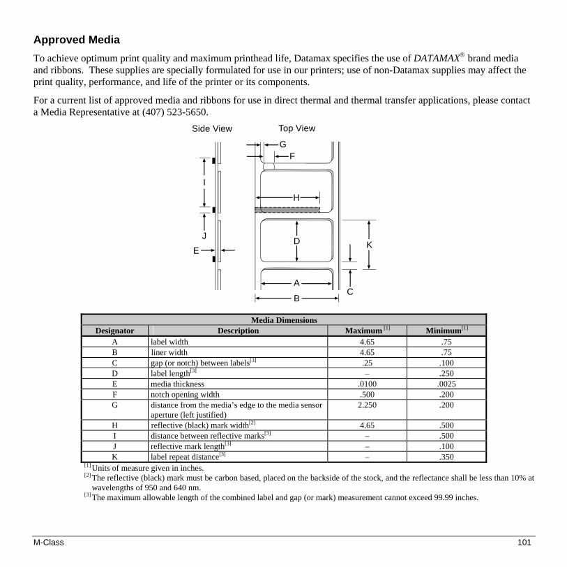
M-Class 101
Approved Media
To achieve optimum print quality and maximum printhead life, Datamax specifies the use of DATAMAX® brand media and ribbons. These supplies are specially formulated for use in our printers; use of non-Datamax supplies may affect the print quality, performance, and life of the printer or its components.
For a current list of approved media and ribbons for use in direct thermal and thermal transfer applications, please contact a Media Representative at (407) 523-5650.
EJ
I
C
K
A
B
D
H
FG
Side View Top View
Media Dimensions Designator Description Maximum [1] Minimum[1]
A label width 4.65 .75 B liner width 4.65 .75 C gap (or notch) between labels[3] .25 .100 D label length[3] – .250 E media thickness .0100 .0025 F notch opening width .500 .200 G distance from the media’s edge to the media sensor
aperture (left justified) 2.250
.200
H reflective (black) mark width[2] 4.65 .500 I distance between reflective marks[3] – .500 J reflective mark length[3] – .100 K label repeat distance[3] – .350
[1] Units of measure given in inches. [2] The reflective (black) mark must be carbon based, placed on the backside of the stock, and the reflectance shall be less than 10% at
wavelengths of 950 and 640 nm. [3] The maximum allowable length of the combined label and gap (or mark) measurement cannot exceed 99.99 inches.

102 M-Class

M-Class 103
ASCII Control Code Chart Char Dec Hex Char Dec Hex Char Dec Hex Char Dec Hex Ctrl @ NUL 0 00 32 20 @ 64 40 ` 96 60 Ctrl A SOH 1 01 ! 33 21 A 65 41 a 97 61 Ctrl B STX 2 02 “ 34 22 B 66 42 b 98 62 Ctrl C EXT 3 03 # 35 23 C 67 43 c 99 63 Ctrl D EOT 4 04 $ 36 24 D 68 44 d 100 64 Ctrl E ENQ 5 05 % 37 25 E 69 45 e 101 65 Ctrl F ACK 6 06 & 38 26 F 70 46 f 102 66 Ctrl G BEL 7 07 ‘ 39 27 G 71 47 g 103 67 Ctrl H BS 8 08 ( 40 28 H 72 48 h 104 68 Ctrl I HT 9 09 ) 41 29 I 73 49 i 105 69 Ctrl J LF 10 0A * 42 2A J 74 4A j 106 6A Ctrl K VT 11 0B + 43 2B K 75 4B k 107 6B Ctrl L FF 12 0C , 44 2C L 76 4C l 108 6C Ctrl M CR 13 0D - 45 2D M 77 4D m 109 6D Ctrl N SO 14 0E . 46 2E N 78 4E n 110 6E Ctrl O SI 15 0F / 47 2F O 79 4F o 111 6F Ctrl P DLE 16 10 0 48 30 P 80 50 p 112 70 Ctrl Q DC1 17 11 1 49 31 Q 81 51 q 113 71 Ctrl R DC2 18 12 2 50 32 R 82 52 r 114 72 Ctrl S DC3 19 13 3 51 33 S 83 53 s 115 73 Ctrl T DC4 20 14 4 52 34 T 84 54 t 116 74 Ctrl U NAK 21 15 5 53 35 U 85 55 u 117 75 Ctrl V SYN 22 16 6 54 36 V 86 56 v 118 76 Ctrl W ETB 23 17 7 55 37 W 87 57 w 119 77 Ctrl X CAN 24 18 8 56 38 X 88 58 x 120 78 Ctrl Y EM 25 19 9 57 39 Y 89 59 y 121 79 Ctrl Z SUB 26 1A : 58 3A Z 90 5A z 122 7A Ctrl [ Esc 27 1B ; 59 3B [ 91 5B { 123 7B Ctrl \ FS 28 1C < 60 3C \ 92 5C | 124 7C Ctrl ] GS 29 1D = 61 3D ] 93 5D } 125 7D Ctrl ^ RS 30 1E > 62 3E ^ 94 5E ~ 126 7E Ctrl _ US 31 1F ? 63 3F _ 95 5F 127 7F

104 M-Class
Char Dec Hex Char Dec Hex Char Dec Hex Char Dec Hex Ç 128 80 á 160 A0 192 C0 Ó 224 E0 ü 129 81 í 161 A1 193 C1 ß 225 E1 é 130 82 ó 162 A2 194 C2 Ô 226 E2 â 131 83 ú 163 A3 195 C3 Ò 227 E3 ä 132 84 ñ 164 A4 196 C4 õ 228 E4 à 133 85 Ñ 165 A5 197 C5 Õ 229 E5 å 134 86 a 166 A6 ã 198 C6 µ 230 E6 ç 135 87 ° 167 A7 Ã 199 C7 p 231 E7 ê 136 88 ¿ 168 A8 200 C8 p 232 E8 è 137 89 ® 169 A9 201 C9 Ú 233 E9 è 138 8A 170 AA 202 CA Û 234 EA ï 139 8B 1/2 171 AB 203 CB Ù 235 EB î 140 8C 1/4 172 AC 204 CC ´y 236 EC ì 141 8D ¡ 173 AD 205 CD ´Y 237 ED Ä 142 8E 174 AE 206 CE 238 EE Å 143 8F – 175 AF 207 CF 239 EF É 144 90 176 B0 Ò 208 D0 240 F0 Æ 145 91 177 B1 D 209 D1 ± 241 F1 Æ 146 92 2 178 B2 Ê 210 D2 242 F2 ô 147 93 3 179 B3 Ë 211 D3 3/4 243 F3 ö 148 94 ´ 180 B4 È 212 D4 244 F4 ò 149 95 Á 181 B5 213 D5 245 F5 û 150 96 Â 182 B6 Í 214 D6 ÷ 246 F6 ù 151 97 À 183 B7 Î 215 D7 ¸ 247 F7 ÿ 152 98 © 184 B8 Ï 216 D8 ° 248 F8 Ö 153 99 1 185 B9 217 D9 ¨ 249 F9 Ü 154 9A 186 BA 218 DA · 250 FA Ø 155 9B » 187 BB 219 DB 251 FB £ 156 9C 188 BC 220 DC 252 FC Ø 157 9D ¢ 189 BD 221 DD 253 FD x 158 9E ¥ 190 BE Ì 222 DE 254 FE ƒ 159 9F 191 BF 223 DF 255 FF
Notes: For the hardware handshake XON/XOFF commands: XON = Ctrl Q (DC1) XOFF = Ctrl S (DC3) The Euro character has been added to the table above at 255 (FF) as a Datamax standard for resident bit-mapped fonts
0,1,2,3,4,5,6, and 9 (CG Triumvirate).

M-Class 105
Embedded Fonts and Barcodes All character fonts and barcodes available with the printer are described in this section. Each font and barcode has a name associated with it for use in programming. Human-readable fonts have numeric names while barcode fonts have alpha names.
Fonts
Fonts 0 through 8 use the slash zero (Ø) conventions for distinguishing between the zero and the alphabetic O. The slash can be removed with the label formatting command z. These fonts are non-proportional (monospaced): all of the characters take up the same amount of space when printed.
The Triumvirate font number 9 is a proportional font; each character will take up a different amount of space when printed.
Font Valid ASCII Characters (decimal) Use with Record Structure Type
0 32-127,255 1 32-168, 171, 172, 225,255 2 32-168, 171, 172, 225,255 3 32, 35-38, 40-58, 65-90, 128, 142-144, 146, 153,
154, 156, 157, 165, 168, 225,255 4 32, 35-38, 40-58, 65-90, 128, 142-144, 146, 153,
154, 156, 157, 165, 168, 225,255 5 32, 35-38, 40-58, 65-90, 128, 142-144, 146, 153,
154, 156, 157, 165, 168, 225,255 6 32, 35-38, 40-58, 65-90, 128, 142-144, 146, 153,
154, 156, 157, 165, 168, 225,255 7 32-126 8 32, 48-57, 60, 62, 67, 69, 78, 83, 84, 88, 90
Internal Bit-Mapped
Fonts
9 32-126, 128-169, 171-173, 181-184, 189, 190, 198, 199, 208-216, 222, 224-237, 241, 243, 246-250,255
Smooth Font
*9 Dependent upon selected symbol set; see the Programmers Manual.
Downloadable Scalable Font
* Not available on non-display printers
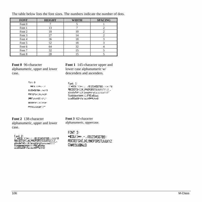
106 M-Class
The table below lists the font sizes. The numbers indicate the number of dots.
FONT HEIGHT WIDTH SPACING Font 0 7 5 1 Font 1 13 7 2 Font 2 18 10 2 Font 3 27 14 2 Font 4 36 18 3 Font 5 52 18 3 Font 6 64 32 4 Font 7 32 15 5 Font 8 28 15 5
Font 0 96-character alphanumeric, upper and lower case.
Font 1 145-character upper and lower case alphanumeric w/ descenders and ascenders.
Font 2 138-character alphanumeric, upper and lower case.
Font 3 62-character alphanumeric, uppercase.

M-Class 107
Font 4 62-character alphanumeric, uppercase.
Font 5 62-character alphanumeric, uppercase.
Font 6 62-character alphanumeric, uppercase.

108 M-Class
Font 7 OCR-A, size I.
Font 8 OCR-B, size III.
Font 9 Internal Triumvirate font. Point sizes are selected by the number in the barcode height. Larger point sizes can be obtained by increasing the height and width multipliers, 48pt and 72pt fonts are generated by doubling the 24pt and 36pt fonts, respectively (see the Programmer's Manual for more information).

M-Class 109
Barcodes
Bar Code fonts have alpha names (left column in the table below). Uppercase alpha names will print barcodes with human-readable interpretations. Lowercase alpha names will print barcodes only. The table is followed by visual samples.
Barcode ID
Type Length Check-sum
Valid ASCII Characters, decimal value representation
A / a Code 39 Varies No 32, 36, 37, 42, 43, 45-57, 65-90 B / b UPC-A (regular) 11 Yes 48-57 Numeric only
Option V used in the 6th & 7th position C / c UPC-E (zero suppression) 6 Yes 48-57 Numeric only D / d Interleaved 2 of 5 (I 2 of 5) Varies No 48-57 Numeric only E / e Code 128 Varies M-103 32-127 F / f EAN-13 12 Yes 48-57 Numeric only.
Option V used in the 7th & 8th position G / g EAN-8 7 Yes 48-57 Numeric only H / h Health Industry Bar Code (Code 39 Mod and 43
checksum) Varies M-43 32, 36-39, 42, 43, 45-57, 65-90
I / i Codabar Varies No 36, 43, 45-58, 65-68 J / j I 2 of 5 with modulo 10 checksum Varies M-10 48-57 Numeric only
K / k Plessey Up to 14 M-10 48-57 Numeric only. Option + is Last Character for Second M-11 checksum
L / l ITF SCC-14/ I 2 of 5 Shipping Container Code 13 M-10 48-57 Numeric only M / m 2 digit UPC addendum 2 Yes 48-57 Numeric only N / n 5 digit UPC addendum 5 Yes 48-57 Numeric only O / o Code 93 Varies No 35-38, 42-58, 65-90, 97-122
p Postnet Varies Yes 48-57 Numeric only Q / q SSCC-18/Serial Shipping Container Code 19 Yes 48-57 Numeric only R / r UCC/EAN Code 128
K-Mart NON EDI bar code 18 Yes 48-57 Numeric only
S / s UCC/EAN 128 Random Weight 34 + Yes 48-57 Numeric only T / t Telepen Varies Yes Alphanumeric U UPS MaxiCode 84 Yes Alphanumeric u UPS MaxiCode with Byte Count Specified Yes Alphanumeric v FIM 1 No A, B, C, D z PDF417 Varies Yes All Z PDF417 with Byte Count Specified Yes All
W1c DataMatrix Varies Yes All 8-bit values W1C DataMatrix with Byte Count Specified Yes All 8-bit values W1d QR Code – Auto format Varies Yes Alphanumeric W1D QR Code – Manual format Varies Yes Single-byte or Kanji double-byte W1f Aztec Varies Yes All 8-bit values W1F Aztec with Byte Count Specified Yes All 8-bit values *W1g USD-8 (Code 11) – Non-Human Readable Varies Yes, C&K 0 through 9 and “-“ *W1G USD-8 (Code 11) - Human Readable Varies Yes, C&K 0 through 9 and “-“ *WI EAN128 (Code 128 with Auto Subset Switching
between B/C) Varies Yes Alphanumeric

110 M-Class
Continued…
Barcode ID
Type Length Check-sum Valid ASCII Characters, decimal value representation
*WJ Code 128 Auto Varies Yes Alphanumeric Reduced Space Symbology (RSS); (RSS-14, Truncated, Stacked, Stacked Omni-directional, and Limited)
13 Yes 0 through 9 *W1k
RSS Expanded Varies Yes Subset of ISO646 including Alphanumeric W1T TCIF Linked Barcode 3 of 9 (TLC39) Varies No Alphanumeric W1z MicroPDF417 Varies Yes All 8-bit values W1Z MicroPDF417 with Byte Count Specified Yes All 8-bit values
* Not available on non-display printers
Barcode A Code 39
Barcode B UPC-A (regular)
Barcode C UPC-E (zero suppression)
Barcode D Interleaved 2 of 5
Barcode E Code 128
Barcode F EAN-13
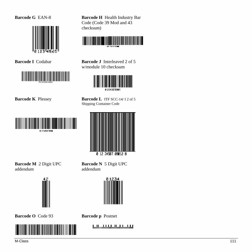
M-Class 111
Barcode G EAN-8
Barcode H Health Industry Bar Code (Code 39 Mod and 43 checksum)
Barcode I Codabar
Barcode J Interleaved 2 of 5 w/module 10 checksum
Barcode K Plessey
Barcode L ITF SCC-14/ I 2 of 5 Shipping Container Code
Barcode M 2 Digit UPC addendum
Barcode N 5 Digit UPC addendum
Barcode O Code 93
Barcode p Postnet

112 M-Class
Barcode Q SSCC-18/Serial Shipping Container Code
Barcode R UCC/EAN Code 128 KMART NON EDI
Barcode S UCC/EAN 128 Random Weight
Barcode T Telepen
Barcode u UPS MaxiCode

M-Class 113
Barcode v FIM
Barcode z PDF417
Bar Code W1c: DataMatrix
Bar Code W1d: QR Code
Bar Code W1f: Aztec
Bar Code W1g: USD-8 (Code 11)
Bar Code WI: EAN128 (Code 128 with Auto Subset Switching
between B/C)
Bar Code WJ: Code 128 Auto
Bar Code W1k: RSS
(Reduced Space Symbology)
Bar Code W1z: MicroPDF417

114 M-Class
Bar Code W1T: TCIF Linked Barcode 3 of 9 (TLC39)

M-Class 115
Optional Internal Ethernet Printer Server (printers with display only) Indicators and Connector
10M Indicates a valid 10-megabit Ethernet connection is present when lit.
100M Indicates a valid 100-megabit Ethernet connection is present when lit.
RX Flashes when data is being received by the printserver.
TX Flashes when data is being transmitted by the printserver.
10M
100M
RX
TX
M-Class EthernetPrint Server
10 Meg. EthernetConnection Indicator
100 Meg. EthernetConnection Indicator
Data Transmit IndicatorData Received Indicator
10M/100M Ethernet ConnectorRJ-45 Connector
Setup and Configuration The Internal Ethernet Print Server can be configured in one of two ways: > Using ‘IP Discovery’ (DHCP); or, > Using a static IP set using the printer’s front panel.
Note: The factory default has IP Discovery ‘Enabled’. If you do not wish to use the IP Discovery function be sure to set it to ‘Disable’ using the printers front panel before connecting and powering on the printer.

116 M-Class
Configuration Using IP Discovery (DHCP, BootP, and RARP) Once the Ethernet Print Sever has been installed and connected, plug in the power cord and Ethernet cable then turn the printer’s power switch ‘On’. DHCP, BootP, and RARP are server services that provide a method for assigning and maintaining IP addresses. The Print Server obtains IP information from this service. The factory default has IP Discovery enabled. The Print Server makes IP requests at power-up. If using this method of discovery, after the connection is established print a Configuration Label (see below) from the printer to obtain the IP Address and then use it to install your printer port and driver to complete your setup.
Note: Depending upon your server, you may have to wait a minute or two for the assigned IP Address to appear on the Configuration Label.
To print a configuration label: With the printer on, loaded with media (at least 4 inches wide) and ribbon (if printing with thermal transfer media). Press the button once, then use the FWD button scroll to ‘PRINT CONFIGURATION’ and press the button again to print.
COMMUNICATIONSSERIAL PORT A:
BAUD RATE9600
PROTOCOLBOTH
PARITYNONE
DATA BITS8
STOP BITS1
SERIAL PORT B:NOT INSTALLED
PARALLEL PORT A:PORT DIRECTION
UNI-DIRECTIONALUSB PORT
INSTALLED
NIC ADAPTER:MAC:00-0d-70-00-00-09IP ADDRESS
168.24.12.192SUBNET MASK
255.255.255.255GATEWAY
168.24.254.254SNMPTRAP DESTINATION
000.000.000.000IP DISCOVERY
ENABLED
HOST SETTINGS:HOST TIMEOUT
10 secCONTROL CODES
STANDARD CODESFEEDBACK CHARACTERS
DISABLED
PRINT CONTROLHEAT
10PRINT SPEED
8.0 in/secFEED SPEED
8.0 in/secREVERSE SPEED
4.0 in/secROW OFFSET
00.00 inchesCOLUMN OFFSET
00.00 inchesPRESENT DISTANCE
0.00 inchesCUSTOM ADJUSTMENTS:
DARKNESS32
CONTRAST32
ROW ADJUST0 DOTS
COLUMN ADJUST0 DOTS
PRESENT ADJUST64 DOTS
PRINTER OPTIONSMODULES
A: NOT INSTALLEDB: NOT INSTALLEDD: NOT INSTALLEDF: NOT INSTALLEDG: NOT INSTALLEDX: NOT INSTALLEDY: NOT INSTALLEDZ: NOT INSTALLED
PRESENT SENSOR:MODE
DISABLEDRETRACT DELAY
0 X 10mS
Assigned IPAddress
Once you have obtained the assigned IP from the configuration label you can then install the port and printer driver using the Windows® ‘Add a Printer Wizard’. See section, Installing the Printer Driver and Port in this document.

M-Class 117
Configuration Using a Static IP Address Once the Ethernet Print Sever has been installed, plug in the power cord, but do not connect the Ethernet cable, then turn the printer’s power switch ‘On’.
1. Verify the printer is in the ‘Ready Mode’
!
XFE!21;27B!13KVM3114!SFBEZ!
2. Press the MENU button to enter the printer’s menu.
NFOV!NPEF!NFEJB!TFUUJOHT!
3. Using the FWD button scroll to ‘COMMUNICATIONS’ and press the button.
NFOV!NPEF!DPNNVOJDBUJPOT!
4. Using the FWD button scroll to ‘NIC ADAPTER’ and press the button.
DPNNVOJDBUJPOT!OJD!BEBQUFS!
5. Using the FWD button scroll to ‘IP DISCOVERY’ and press the button.
OJD!BEBQUFS!JQ!EJTDPWFSZ!
6. Using the FWD button scroll to ‘DISABLED’ and press the button.
JQ!EJTDPWFSZ!+EJTBCMFE!
7. Press the button once to return to the ‘NIC ADAPTER’ menu level. Then use the FWD button scroll to ‘IP ADDRESS’ and press the
button.
OJD!BEBQUFS!JQ!BEESFTT!
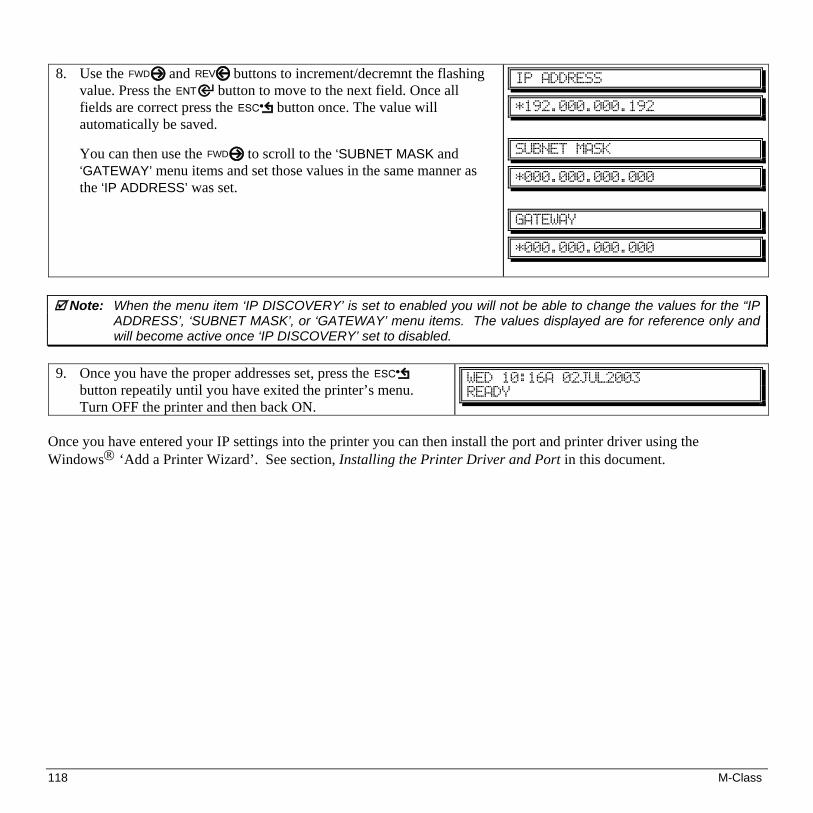
118 M-Class
8. Use the FWD and REV buttons to increment/decremnt the flashing
value. Press the button to move to the next field. Once all fields are correct press the button once. The value will automatically be saved.
You can then use the FWD to scroll to the ‘SUBNET MASK and
‘GATEWAY’ menu items and set those values in the same manner as the ‘IP ADDRESS’ was set.
JQ!BEESFTT!
+2:3/111/111/2:3!
TVCOFU!NBTL!
+111/111/111/111!
HBUFXBZ!
+111/111/111/111!
Note: When the menu item ‘IP DISCOVERY’ is set to enabled you will not be able to change the values for the “IP ADDRESS’, ‘SUBNET MASK’, or ‘GATEWAY’ menu items. The values displayed are for reference only and will become active once ‘IP DISCOVERY’ set to disabled.
9. Once you have the proper addresses set, press the
button repeatily until you have exited the printer’s menu. Turn OFF the printer and then back ON.
XFE!21;27B!13KVM3114!SFBEZ!
Once you have entered your IP settings into the printer you can then install the port and printer driver using the Windows® ‘Add a Printer Wizard’. See section, Installing the Printer Driver and Port in this document.

M-Class 119
Using the HTML Pages The printer has resident HTML (Web) pages that allow configuration of network and printer settings as well as performing status queries and diagnostic tests. To configure the Print Server and other internal printer settings you can access the printer via HTML pages using any Web browser. 1. In your Web browser, choose File -> Open.
2. Enter the IP address of the Print Server and press Enter. (The default IP Address is: 192.0.0.192)
Note: Consult with your system administrator for all necessary address, printer, and protocol information. To change
these settings you will be asked for an authentication password. Type sysadm and click “Apply”. Next you should see the Print Server’s Unit Information page:

120 M-Class
Network Status
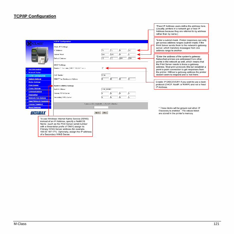
M-Class 121
TCP/IP Configuration

122 M-Class
System Settings, Media Settings, and Print Control Many of the printer's internal menu settings can be controlled from the following next six screens. This allows the user to adjust many of the printer's settings remotely without using the printer's front panel. For more information on the function of these settings see the M-Class Operator’s Manual.
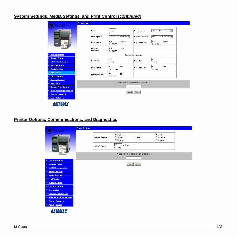
M-Class 123
System Settings, Media Settings, and Print Control (continued)
Printer Options, Communications, and Diagnostics
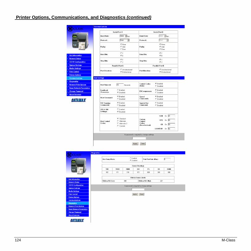
124 M-Class
Printer Options, Communications, and Diagnostics (continued)

M-Class 125
Network Print Options
Reset Network Parameters

126 M-Class
Change Password

M-Class 127
Installing the Printer Driver and Port Windows 95/98 Driver and Port Installation Insert the M-Class CD-ROM into your computer’s drive.
The M-Class CD-ROM should start automatically, if it does not Click ‘Start’ and then select ‘Run’ from the window’s menu. Then type d:\datamax.exe
(where “d:” is the location of the CD-ROM)
1 At the main screen click on your printer model.
2 Now click “Install Windows Driver”.
3 The following screen should appear, click ‘Next>’.
4 Make sure that ‘Local Printer’ is selected and then click ‘Next’.
5 Click on ‘Have Disk’.
6 Click ‘Browse’.

128 M-Class
7 Browse to the “Drivers” folder on the CD-ROM, make sure the file “Datamax for 95, 98, me, 2000, and xp.inf” is selected and click ‘OK’.
8 Click ‘OK’.
9 Select the ‘M-4208’ printer from the list and then click ‘Next’.
10 Your computer will now copy the necessary files from the CD-ROM.
11 When prompted to choose a port, select ‘FILE’ for now and click ‘Next’. You will set up the network port from the printer properties later.
12 Name your printer in the ‘Printer name:’ field. Next select whether or not to set this printer as your default printer. Then Click ‘Finish’.
13 From the Windows desktop click ‘Start’ / ‘Settings’ / ‘Printers’.
14 Once the Printers window opens, right-click on the printer icon and select ‘Properties’ from the drop down menu.

M-Class 129
15 Click on the ‘Details’ tab and then click ‘Add Port’.
16 In the ‘Add Port’ window, Select ‘Other’ and “Seagull Scientific Port” and then click ‘OK’.
17 In the ‘Name or IP Address:’ field enter the IP address of your printer. The ‘Port Number’ and ‘Port Name’ fields do not need to be changed. When finished click “OK’
18 Click ‘Apply’ and then click ‘OK’. The driver and port installation is now complete. The printer can be selected through any window’s application.

130 M-Class
Windows NT 4.0 Driver and Port Installation Insert the M-Class CD-ROM into your computer’s drive.
The M-Class CD-ROM should start automatically, if it does not Click ‘Start’ and then select ‘Run’ from the window’s menu. Then type d:\datamax.exe
(where “d:” is the location of the CD-ROM)
1 At the main screen click on your printer model.
2 Now click “Install Windows Driver”.
3 Make sure that ‘My Computer’ is selected and then click ‘Next’.
4 Click ‘Add Port’.

M-Class 131
5 Double-click ‘LPR Port’.
6 In the top field enter the IP address of your printer. In the bottom field enter PORT1. When finished click “OK’.
7 Click ‘Close’
8 Click ‘Next’.
9 Click on ‘Have Disk’.
10 Click ‘Browse’.

132 M-Class
11 Browse to the “Drivers\Nt4\” folder on the CD-ROM, make sure the file “Datamax for nt 4.0 only” is selected and click ‘Open’.
12 Click ‘OK’.
13 Select the ‘M-4208’ printer from the list and then click ‘Next’.
14 Name your printer in the ‘Printer name:’ field. Next select whether or not to set this printer as your default printer. Then Click ‘Next’.
15 Select whether or not to share this printer on your network. Then Click ‘Next’.
16 Select ‘No’ then Click ‘Finish’.
17 Your computer will now copy the necessary files from the CD-ROM.
The driver and port installation is now complete. The printer can be selected through any window’s application.
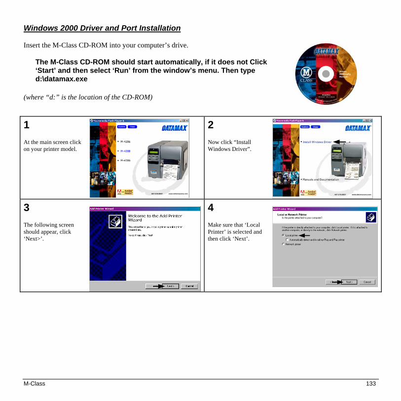
M-Class 133
Windows 2000 Driver and Port Installation Insert the M-Class CD-ROM into your computer’s drive.
The M-Class CD-ROM should start automatically, if it does not Click ‘Start’ and then select ‘Run’ from the window’s menu. Then type d:\datamax.exe
(where “d:” is the location of the CD-ROM)
1 At the main screen click on your printer model.
2 Now click “Install Windows Driver”.
3 The following screen should appear, click ‘Next>’.
4 Make sure that ‘Local Printer’ is selected and then click ‘Next’.
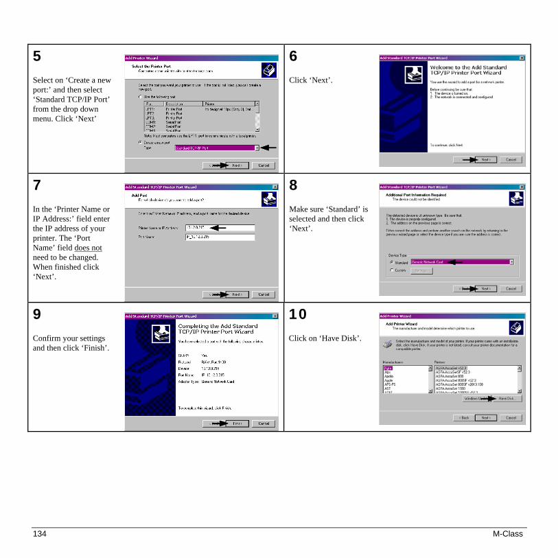
134 M-Class
5 Select on ‘Create a new port:’ and then select ‘Standard TCP/IP Port’ from the drop down menu. Click ‘Next’
6 Click ‘Next’.
7 In the ‘Printer Name or IP Address:’ field enter the IP address of your printer. The ‘Port Name’ field does not need to be changed. When finished click ‘Next’.
8 Make sure ‘Standard’ is selected and then click ‘Next’.
9 Confirm your settings and then click ‘Finish’.
10 Click on ‘Have Disk’.

M-Class 135
11 Click ‘Browse’.
12 Browse to the “Drivers” folder on the CD-ROM, make sure the file “Datamax for 95, 98, me, 2000, and xp.inf” is selected and click ‘OK’.
13 Click ‘OK’.
14 Select the ‘M-4208’ printer from the list and then click ‘Next’.
15 Name your printer in the ‘Printer name:’ field. Next select whether or not to set this printer as your default printer. Then Click ‘Next’.
16 Select whether or not to share this printer on your network. Then Click ‘Next’

136 M-Class
17 Select ‘No’ then Click ‘Next’.
18 Confirm your settings and then click ‘Finish’.
19 If prompted with the "Digital Signature Not Found" window, click ‘Yes’ to continue installation.
20 Your computer will now copy the necessary files from the CD-ROM. The driver and port installation is now complete. The printer can be selected through any window’s application.

M-Class 137
Windows XP Driver and Port Installation Insert the M-Class CD-ROM into your computer’s drive.
The M-Class CD-ROM should start automatically, if it does not Click ‘Start’ and then select ‘Run’ from the window’s menu. Then type d:\datamax.exe
(where “d:” is the location of the CD-ROM)
1 At the main screen click on your printer model..
2 Now click “Install Windows Driver”.
3 The following screen should appear, click ‘Next>’.
4 Make sure that ‘Local Printer’ is selected and then click ‘Next’.

138 M-Class
5 Select on ‘Create a new port:’ and then select ‘Standard TCP/IP Port’ from the drop down menu. Click ‘Next’
6 Click ‘Next’.
7 In the ‘Printer Name or IP Address:’ field enter the IP address of your printer. The ‘Port Name’ field does not need to be changed. When finished click “Next’.
8 Make sure ‘Standard’ is selected and then click ‘Next’.
9 Confirm your settings and then click ‘Finish’.
10 Click on ‘Have Disk’.

M-Class 139
11 Click ‘Browse’.
12 Browse to the “Drivers” folder on the CD-ROM, make sure the file “Datamax for 95, 98, me, 2000, and xp.inf” is selected and click ‘OK’.
13 Click ‘OK’.
14 Select the ‘M-4208’ printer from the list and then click ‘Next’.
15 Name your printer in the ‘Printer name:’ field. Next select whether or not to set this printer as your default printer. Then Click ‘Next’.
16 Select whether or not to share this printer on your network. Then Click ‘Next’

140 M-Class
17 Select ‘No’ then Click ‘Next’.
18 Confirm your settings and then click ‘Finish’.
19 If prompted with the "Digital Signature Not Found" window, click ‘Yes’ to continue installation.
20 Your computer will now copy the necessary files from the CD-ROM. The driver and port installation is now complete. The printer can be selected through any window’s application.
M-Class 141
Menu System Multi-Language Support (display-equipped printers only)
This printer provides the user with the ability to download new menu system languages and/or replace the Datamax provided translations. A Microsoft® Excel Spreadsheet defines the menu dictionary – the user adds a new language column or modifies an existing column in the spreadsheet, clicks on the ‘Generate DPL file(s)’ radio button and sends the generated DPL file(s) to the printer. Here are the highlights and restrictions of the feature:
• The printer can register up to 10 different display languages, including EFIGS.
• The EFIGS languages and any additional languages are stored on Module Y: a 64KB Flash Module located on the Main PCB.
• It is okay to download menu files generated for a lesser firmware revision to new firmware – any messages that are not defined are displayed in English.
• For the procedures below, the printer will accept the menu downloads from any available port.
• The language creation programs support Windows® 95, Windows® 98, Windows® NT, and Windows® 2000.
Required Software Comment Microsoft® Excel 97 Must be purchased by user. Img2dl.exe** Program used during the process to
create DPL file. Gemmsgxls.xls** Menu Dictionary
**Datamax recommends that the Img2dl.exe and Gemmsgxls.xls files reside in the same directory.
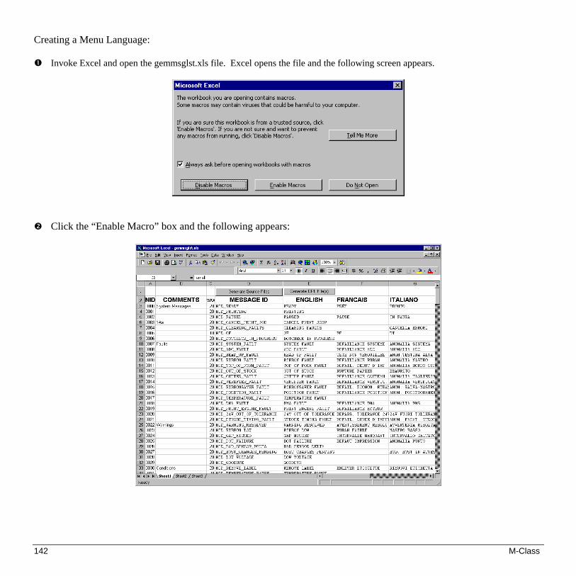
142 M-Class
Creating a Menu Language: Invoke Excel and open the gemmsglst.xls file. Excel opens the file and the following screen appears.
Click the “Enable Macro” box and the following appears:

M-Class 143
Click On Column J and enter your new language, or modify an existing one.
Tips:
A) Message Size – When entering new messages, reference the ‘MAX’ column: this is the maximum number of characters allowed for this field. Warnings are displayed when the number of characters is exceeded or when trying to modify the MAX value. Beware that “cutting” and “pasting” fields could defeat this warning system.
B) Two Line Messages – Some of the message are displayed as two lines. These are indicated in the comment fields.
C) Comments – This field can be modified with no effect.
When editing has been completed, highlight all of the columns you desire to create (more than one language may be selected) by pressing the letter above the column.
Press the Generate DPL File(s) radio button. A file will be generated for each of the
selected columns and Excel will provide confirmation. (Example: small.ls)
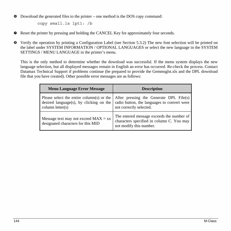
144 M-Class
Download the generated files to the printer – one method is the DOS copy command:
copy small.ls lpt1: /b Reset the printer by pressing and holding the CANCEL Key for approximately four seconds.
Verify the operation by printing a Configuration Label (see Section 5.3.2) The new font selection will be printed on
the label under SYSTEM INFORMATION / OPTIONAL LANGUAGES or select the new language in the SYSTEM SETTINGS / MENU LANGUAGE in the printer’s menu.
This is the only method to determine whether the download was successful. If the menu system displays the new
language selection, but all displayed messages remain in English an error has occurred. Re-check the process. Contact Datamax Technical Support if problems continue (be prepared to provide the Gemmsglst.xls and the DPL download file that you have created). Other possible error messages are as follows:
Menu Language Error Message Description
Please select the entire column(s) or the desired language(s), by clicking on the column letter(s)
After pressing the Generate DPL File(s) radio button, the languages to convert were not correctly selected.
Message text may not exceed MAX = xx designated characters for this MID
The entered message exceeds the number of characters specified in column C. You may not modify this number.

M-Class 145
Advanced File Handling Information
The Standard Datamax Printer leaves the factory with EFIGS loaded into module Y. At this point, Module Y is LOCKED and will only accept additional Language Downloads.
After downloading a language update, Module Y is left UNLOCKED until the printer is reset or power is cycled. In
this state, Module Y will accept font, image and label format downloads. The module will also honor the Clear Module request. Therefore, following an update it is recommended that a reset be performed to lock the module; otherwise, a software package may ‘Clear All Modules’ thus destroying the new menu language(s).
Module Y can be UNLOCKED by sending this DPL string: <STX>KpY0.
To restore the factory generated EFIGS image, download the file 832296.08A to the printer. This file is located on the Datamax FTP site. The letter at the end of the file name (e.g., A) specifies the revision. The latest revision will be available on the FTP site.
Downloading the same language twice will automatically delete the first occurrence, but will not free the memory
space. Use the Pack Module feature (see Section 5.1.4) or reload the FIGS file to free the space. Deletion of the selected language will set the printer to English.
The total number of languages that the printer can now accept is limited to 10, but this number is dependent upon the
size of each language translation. The translation size will vary with the number of messages that are translated for that particular language. Current complete language files are about 7,000 bytes each but with product growth, the total number of languages is expected to drop to seven.

146 M-Class
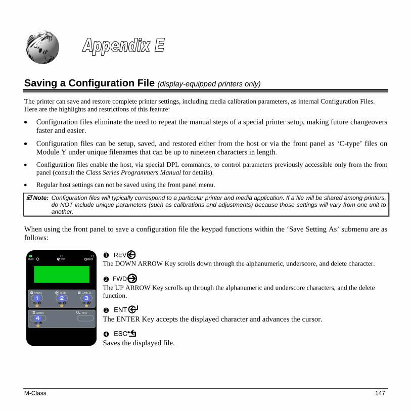
M-Class 147
Saving a Configuration File (display-equipped printers only)
The printer can save and restore complete printer settings, including media calibration parameters, as internal Configuration Files. Here are the highlights and restrictions of this feature:
• Configuration files eliminate the need to repeat the manual steps of a special printer setup, making future changeovers faster and easier.
• Configuration files can be setup, saved, and restored either from the host or via the front panel as ‘C-type’ files on Module Y under unique filenames that can be up to nineteen characters in length.
• Configuration files enable the host, via special DPL commands, to control parameters previously accessible only from the front panel (consult the Class Series Programmers Manual for details).
• Regular host settings can not be saved using the front panel menu.
Note: Configuration files will typically correspond to a particular printer and media application. If a file will be shared among printers, do NOT include unique parameters (such as calibrations and adjustments) because those settings will vary from one unit to another.
When using the front panel to save a configuration file the keypad functions within the ‘Save Setting As’ submenu are as follows:
REV The DOWN ARROW Key scrolls down through the alphanumeric, underscore, and delete character.
FWD The UP ARROW Key scrolls up through the alphanumeric and underscore characters, and the delete function.
The ENTER Key accepts the displayed character and advances the cursor.
Saves the displayed file.
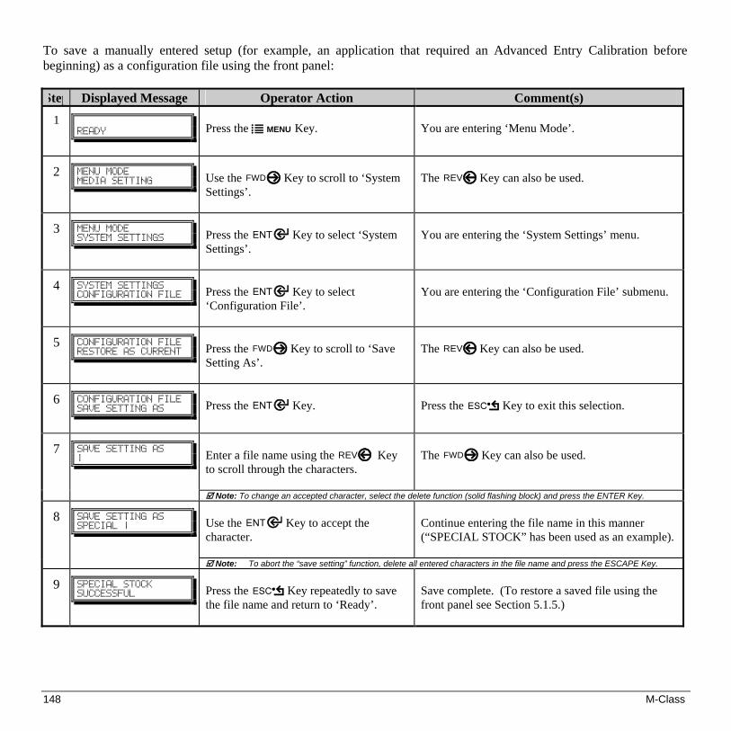
148 M-Class
To save a manually entered setup (for example, an application that required an Advanced Entry Calibration before beginning) as a configuration file using the front panel: Step Displayed Message Operator Action Comment(s)
1
!!SFBEZ!
Press the MENU Key.
You are entering ‘Menu Mode’.
2
NFOV!NPEF!!NFEJB!TFUUJOH!
Use the FWD Key to scroll to ‘System Settings’.
The REV Key can also be used.
3
NFOV!NPEF!TZTUFN!TFUUJOHT!
Press the Key to select ‘System Settings’.
You are entering the ‘System Settings’ menu.
4
TZTUFN!TFUUJOHT!!DPOGJHVSBUJPO!GJMF!
Press the Key to select ‘Configuration File’.
You are entering the ‘Configuration File’ submenu.
5
DPOGJHVSBUJPO!GJMF!SFTUPSF!BT!DVSSFOU!
Press the FWD Key to scroll to ‘Save Setting As’.
The REV Key can also be used.
6
DPOGJHVSBUJPO!GJMF!TBWF!TFUUJOH!BT!
Press the Key.
Press the Key to exit this selection.
Enter a file name using the REV Key to scroll through the characters.
The FWD Key can also be used.
7
TBWF!TFUUJOH!BT!}!
Note: To change an accepted character, select the delete function (solid flashing block) and press the ENTER Key. Use the Key to accept the character.
Continue entering the file name in this manner (“SPECIAL STOCK” has been used as an example).
8
TBWF!TFUUJOH!BT!!TQFDJBM!}!
Note: To abort the “save setting” function, delete all entered characters in the file name and press the ESCAPE Key.
9
TQFDJBM!TUPDL!TVDDFTTGVM!
Press the Key repeatedly to save the file name and return to ‘Ready’.
Save complete. (To restore a saved file using the front panel see Section 5.1.5.)

M-Class 149
GPIO Port Description The printer can easily be programmed to interface with most applicator devices. The GPIO functions can be enabled and configured via the menu system of the printer (for non-display printers, see Section 4; or for display-equipped printers, see Section 5). Configured parameters are stored in non-volatile memory and saved for subsequent power-ups. Printing with GPIO: When the GPIO functions are enabled, the printer will not print a label until the “Start of Print” signal goes active.
Note: When a label is ready to print but awaiting a Start of Print signal, the prompting operation differs slightly depending upon equipment:
Non-Display Models – The STOP LED will flash.
Display-Equipped Models – The display will indicate “WAITING FOR SIGNAL.”
GPIO Port Configuration The connection to the GPIO signals can be accessed via the Option Port connector (an 8-pin Molex Microfit 3, P/N 44300-800) on the front of the printer, or via the J6 connector (an AMP, P/N 640456-8) on the Main PCB. The pin-outs for the respective connectors (as viewed when facing the printer) are as follows:
Option Port Connector Main PCB – Connector J6
8 6 4 2
7 5 3 1
1 2 3 4 5 6 7 8
Each GPIO pin function is detailed in the table below:

150 M-Class
M-Class GPIO Port Connections and Functions
Pin Number(s)
Signal Name
Signal State
Signal Direction[1] Signal Description [2]
1 Vcc +5 VDC 2.5 Amp (fused) Output Printer +5 VDC
2 Printer Fault Low Output Goes low upon printer detection of a fault condition.
3 Spare Reserved Input Must be pulled high (see sample SOP circuit, below).
4 Start of Print (SOP) Programmable Input
When active, will begin print. Recommend only setting this signal to ACTIVE LOW. When ready to print a label, the applicator should hold this signal low for at least 50ms – or until EOP goes not active. See sample SOP circuit, below.
5 End of Print (EOP) Programmable Output
Signifies the end of the print process. Can be monitored to initiate next Start of Print sequence. Minimum signal time 30ms.
6 & 8 Signal Ground Ground N/A Ground
7 +24 VDC 1.6 Amp (fused) Output Printer +24 VDC
[1] Given relative to the printer. [2] The operation of this multi-function port is configuration dependent. For GPIO operation, disable all optional functions not used (i.e., Present
Sensor and Cutter) and set GPIO to “YES” (or on display-equipped models set GPIO Device to “APPLICATOR”). Use the Configuration Set command (<STX>Kc), or program the selections on non-display models via the “Printer Setup Menu List” or on display-equipped models via the “Menu System.”
M-Class Sample SOP Circuit
Pin 3 should be pulled to +5VDC. In additional, connections
for the external Start of Print control can either be directly made
to Pin 4 of the Option Port (or Main PCB connector) using a
TTL-level input, or via an interface circuit (similar to the one
shown). For more information, see the table below.
1
8
Vcc
Gnd
GPIO Connector Pin Number
3Spare
4SOP
1K O1K O

M-Class 151
GPIO Port Specifications Vin max 5.5 VDC maximum input into any pin
VIH 3.8 VDC minimum (high level input voltage) VIL 1.65 VDC maximum (low level input voltage) IOH -8 mA typical, - 25 mA maximum (high level output current) IOL 8 mA typical 25 mA maximum (low level output current) VOH IOH = -8 mA, minimum 3.8 VDC VOL IOL = 8 mA, maximum .44 VDC

152 M-Class
M-Class 153
Datamax Barcode Products Limited Warranty Statement
M-Class™ Printer Printer
Datamax warrants to Purchaser that under normal use and service, the M-Class™ Printer, (with the exception of the thermal printhead) purchased hereunder shall be free from defects in material and workmanship for a period of (365) days from the date of shipment by Datamax.
Expendable and/or consumable items or parts such as lamps, fuses, labels and ribbons are not covered under this warranty. This warranty does not cover equipment or parts which have been misused, altered, neglected, handled carelessly, or used for purposes other than those for which they were manufactured. This warranty also does not cover loss, damages resulting from accident, or damages resulting from unauthorized service. Thermal Printhead
This warranty is limited to a period of one year, (365 days), or 1,000,000 linear inches of use, whichever comes first, for the M-Class™ thermal printhead. This one year (365 days) warranty is valid only if a Datamax - approved thermal label media is used, as defined in the then current Datamax list of approved thermal/thermal transfer media, a copy of which is available from Datamax. Failure to use Datamax-approved media is justification for invalidation of this thermal printhead warranty. This warranty does not cover printheads which have been misused, altered, neglected, handled carelessly, or damaged due to improper cleaning or unauthorized repairs.

154 M-Class
Warranty Service Procedures
If a defect should occur during the warranty period, the defective unit shall be returned, freight and insurance prepaid, in the original shipping containers, to Datamax at: 4501 Parkway Commerce Blvd., Orlando, Florida, 32808. A Return Material Authorization (RMA) number must be issued before the product can be returned. To open an RMA please call the Datamax Customer Service Department at (407) 523-5550. Please include your RMA number on the outside of the box and on the shipping document. Include a contact name, action desired, a detailed description of the problem(s), and examples when possible with the defective unit. Datamax shall not be responsible for any loss or damages incurred in shipping. Any warranty work to be performed by Datamax shall be subject to Datamax’s confirmation that such product meets Datamax warranty. In the event of a defect covered by its warranty, Datamax will return the repaired or replaced product to the Purchaser at Datamax’s cost.
With respect to a defect in hardware covered by the warranty, the warranty shall continue in effect until the end of the original warranty period, or for sixty (60) days after the repair or replacement, whichever is later. General Warranty Provisions
Datamax makes no warranty as to the design, capability, capacity or suitability of any of its hardware, supplies, or software.
Software is licensed on an “as is” basis without warranty. Except and to the extent expressly provided in this warranty and in lieu of all other warranties, there are no warranties, expressed or implied, including, but not limited to, any warranties of merchantability or fitness for a particular purpose.
Purchaser shall be solely responsible for the selection, use, efficiency and suitability of Datamax’s products. Limitation of Liability
In no event shall Datamax be liable to the purchaser for any indirect, special or consequential damages or lost profits arising out of or relating to Datamax’s products, or the performance or a breach thereof, even if Datamax has been advised of the possibility thereof. Datamax’s liability, if any, to the purchaser or to the customer of the purchaser hereunder shall in no event exceed the total amounts paid to Datamax hereunder by the purchaser for a defective product.
In no event shall Datamax be liable to the purchaser for any damages resulting from or related to any failure or delay of Datamax in the delivery or installation of the computer hardware, supplies or software or in the performance of any services.
Some states do not permit the exclusion of incidental or consequential damages, and in those states the foregoing limitations may not apply. The warranties here give you specific legal rights, and you may have other legal rights which vary from state to state.
M-Class 155
alphanumeric Consisting of alphabetic, numeric, punctuation and other symbols. backing material The silicon-coated paper carrier material to which labels with adhesive backing are affixed.
Also referred to as “liner”. bar code A representation of alphanumeric information in a pattern of machine-readable marks. The basic
categories are divided into one-dimensional (UPC, Code 39, Postnet, etc.) and two-dimensional barcodes (DataMatrix, MaxiCode, PDF417, etc.).
burn line The row of thermal elements in the printhead that create the images on the media. calibration The process through which sensor readings are entered into the printer for correct sensor function (for
example, detection of a given media type) and TOF positioning. character set The entire complement of alphanumeric symbols contained in a given font. checksum An alphanumeric error detection method used in many bar code symbologies for informational
security. continuous media An uninterrupted roll or box of label or tag media that contains no gap, notch, or mark to
separate individual labels or tags. core diameter The inside diameter measurement of the cardboard core at the center of a ribbon or media roll. cutter A mechanical device with a rotary or guillotine type blade used to cut labels or tags following printing. defaults The functional setting values returned following a factory reset of the printer. diagnostics Programs used to locate and diagnose hardware problems. die-cut media Media that has been cut into a pattern using a press, where the excess paper is removed leaving
individual labels, with gaps between them, attached to a backing material. direct thermal The printing method that uses a heat sensitive media and only the heat of the thermal printhead to
create an image on the label.

156 M-Class
direct thermal media Media coated with special chemicals that react and darken with the application of heat. DPI (dots per inch) A measurement of print resolution, rated in the number of thermal elements contained in one
inch of the printhead. Also referred to as “resolution”. DPL (Datamax Programming Language) programming commands used specifically for control of and label
production in Datamax printers. A complete listing of commands can be found in the Programmer’s Manual.
fan-fold Media that is folded and stacked. feed speed The speed at which the media moves under the printhead in non-printed areas and between labels. Flash memory Non-volatile memory (does not require printer power to maintain data) that can be erased and
reprogrammed, used to hold the printer’s operating programs. font A set of alphanumeric characters that share a particular typeface. gap A space between die-cut or notched labels used to sense the top of form. IPS (inches per second) Imperial measurement of printer speeds. label A paper or synthetic printing material, typically with a pressure sensitive adhesive backing. label length The distance from the top of the label to the bottom of the label as it exits the printer. label repeat The distance from the top of one label to the top of the next label. label tracking Excessive lateral (side to side) movement of the media as it travels under the printhead. label width The left to right measurement of the label as it exits the printer. mark Generalized term to indicate the label top of form light. media Generalized term for all types of printing stocks, including: roll fed, continuous, die-cut, reflective, and
fanfold. media hub Device in the printer used to support roll media. media sensor An electronic device equipped with photosensors to detect media and the top of form on die-cut,
notched or reflective media.
M-Class 157
notched stock Media, typically tag stock, with holes or notches in the material that is used to signal the top of form. The printer must be set to ‘gap’ to use this media type.
preprinted media Label stock that contains borders, text, or graphics, floodcoating, etc. perforation Small cuts extending through the backing and/or label material to facilitate their separation. Also
referred to as “perf”. print speed The speed at which the media moves under the printhead during the printing process. reflective media Media imprinted with carbon-based black marks on the underside of the material, which is used
to signal the top of form when the ‘reflective’ sensor is enabled. registration Repeatable top to bottom alignment of printed labels. reverse speed The backward rate of media motion into the printer during tear-off, peel and present and cutting
operations for positioning the label at the start of print position. ribbon An extruded polyester tape with several layers of material, one of which is ink-like, used to produce an
image on the label. Also referred to as “foil”. ribbon wrinkle An undesirable overlapping of the ribbon during the printing process that leads to voids on the
printed label, typically caused by an improper ribbon width adjustment. roll media A form of media that is wound upon a cardboard core. start of print The position on the label where the printing actually begins. tag stock A heavy paper or synthetic printing material, typically featuring a notch or black mark for TOF and no
adhesive backing. thermal transfer The printing method that creates an image by transferring ink from a ribbon onto the media
using the heat from the thermal printhead. TOF (top of form) The start of a new label as indicated by a label gap, notch, mark or programming. void An undesirable blank space in a printed image.

158 M-Class


