Embed Size (px)
Citation preview
Spartan-6 LX9 MicroBoard Tutorial
LwIP Applications Software 201
for the Spartan-6 LX9 MicroBoard
Version 14.4.01 March, 2013

Spartan-6 LX9 MicroBoard Tutorial
Page 2 of 65 2
Table of Contents Overview .......................................................................................................................................... 3 Objectives ........................................................................................................................................ 3 Description of Included lwIP Applications ....................................................................................... 4 Reference Design Requirements ..................................................................................................... 5
Software ....................................................................................................................................... 5 Hardware ..................................................................................................................................... 5
Recommended Reading .................................................................................................................. 5 Supplied Files ................................................................................................................................... 6 Setting Up the S6LX9 MicroBoard ................................................................................................... 7 PC Setup .......................................................................................................................................... 8
Installing the UART Driver and Virtual COM Port ........................................................................ 8 Installing a Serial Console on a Windows 7 Host ......................................................................... 8
Running the Demo Files................................................................................................................... 9 Applications Download ................................................................................................................ 9 RxTest Demo .............................................................................................................................. 12 TxTest Demo .............................................................................................................................. 13 HTTP Server Demo ..................................................................................................................... 15 Echo Server Demo ...................................................................................................................... 17 TFTP Server Demo ...................................................................................................................... 17
Creating the MicroBlaze System ................................................................................................... 18 Hardware Design Block Diagram ............................................................................................... 18 Description of XPS Hardware Modifications .............................................................................. 19 Base System Builder Wizard ...................................................................................................... 20 Customize the Processor System ............................................................................................... 26
MicroBlaze Hardware Options ............................................................................................... 26 Ethernet MAC Hardware Options .......................................................................................... 29 Modify the Bitstream Settings ............................................................................................... 32
Implement the Hardware Design............................................................................................... 34 Create the SDK Workspace ............................................................................................................ 35
Export XPS Hardware Design to the SDK ................................................................................... 35 Description of SDK Software BSP and Linker Modifications ...................................................... 37 Create and Modify the Board Support Package ........................................................................ 38 Create the Software Application ............................................................................................... 46 Description of lwIP Source Code Edits ....................................................................................... 53 Running the Software Applications ........................................................................................... 55
Modify the Webserver Filesystem ................................................................................................ 59 Getting Help and Support .............................................................................................................. 60 Appendix: Installation of USB UART Driver .................................................................................. 61
Download And Install The Required Software ........................................................................... 61 Determining the Virtual COM Port ............................................................................................ 63
Revision History ............................................................................................................................. 65

Spartan-6 LX9 MicroBoard Tutorial
Page 3 of 65
Overview This document describes a basic MicroBlazeTM design implemented and tested on the Xilinx Spartan-6 LX9 MicroBoard. This example design utilizes the light-weight IP (lwIP) protocol stack in raw API mode, with the Xilinx 10/100 soft AXI_Ethernetlite MAC in simple FIFO Interrupt mode. This example design is based on Xilinx Applications Note XAPP1026 (www.xilinx.com/support/documentation/application_notes/xapp1026.pdf) with small modifications to the source software to match the board hardware and to boost performance. Lightweight IP (lwIP) is an open source TCP/IP networking stack for embedded systems. The Xilinx® Software Development Kit (SDK) provides lwIP software customized to run on Xilinx embedded systems containing a MicroBlaze™ processor. This tutorial describes how to utilize the lwIP library to add networking capability to an embedded system. In particular, lwIP is utilized to develop these applications:
TCP/IP echo server
HTTP web server
TFTP server
Receive and transmit throughput tests. This tutorial shows how to build a MicroBlaze Hardware Platform and then create, build, and run an lwIP-enabled software project with networking capability on the Avnet Spartan-6 LX9 MicroBoard.
Objectives When you have completed this tutorial, you will know how to do the following:
Build a MicroBlaze hardware platform capable of running Ethernet networking applications.
Set up an SDK workspace.
Create a BSP that includes the lwIP TCP/IP stack and support for the webserver file system.
Add example lwIP software applications.
Test several networking applications.
Spartan-6 LX9 MicroBoard Tutorial
Page 4 of 65
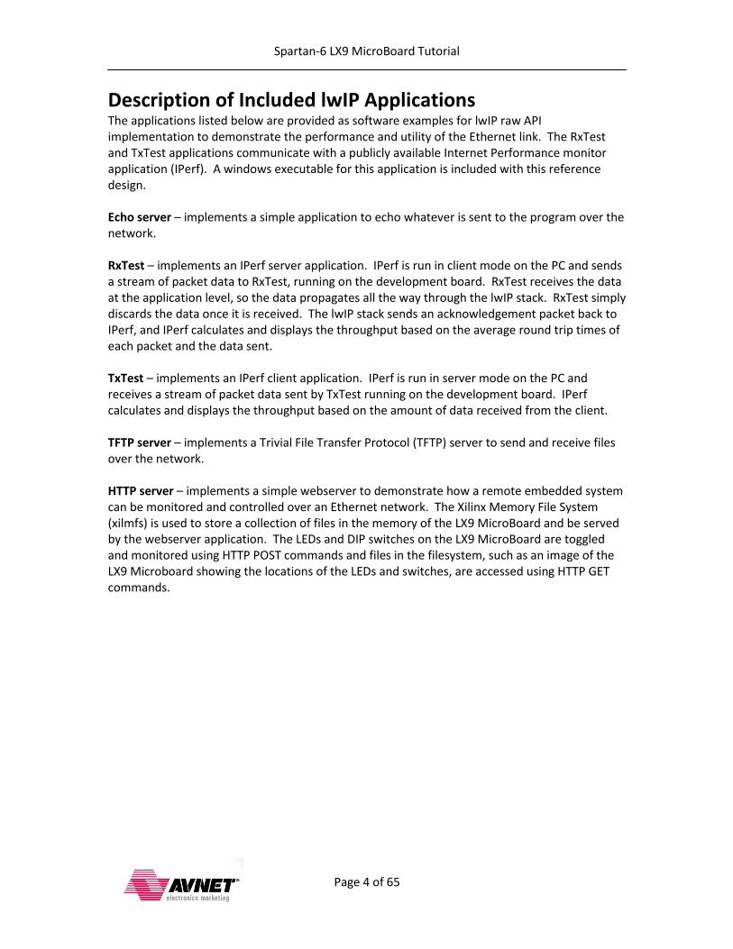
Description of Included lwIP Applications The applications listed below are provided as software examples for lwIP raw API implementation to demonstrate the performance and utility of the Ethernet link. The RxTest and TxTest applications communicate with a publicly available Internet Performance monitor application (IPerf). A windows executable for this application is included with this reference design. Echo server – implements a simple application to echo whatever is sent to the program over the network. RxTest – implements an IPerf server application. IPerf is run in client mode on the PC and sends a stream of packet data to RxTest, running on the development board. RxTest receives the data at the application level, so the data propagates all the way through the lwIP stack. RxTest simply discards the data once it is received. The lwIP stack sends an acknowledgement packet back to IPerf, and IPerf calculates and displays the throughput based on the average round trip times of each packet and the data sent. TxTest – implements an IPerf client application. IPerf is run in server mode on the PC and receives a stream of packet data sent by TxTest running on the development board. IPerf calculates and displays the throughput based on the amount of data received from the client. TFTP server – implements a Trivial File Transfer Protocol (TFTP) server to send and receive files over the network. HTTP server – implements a simple webserver to demonstrate how a remote embedded system can be monitored and controlled over an Ethernet network. The Xilinx Memory File System (xilmfs) is used to store a collection of files in the memory of the LX9 MicroBoard and be served by the webserver application. The LEDs and DIP switches on the LX9 MicroBoard are toggled and monitored using HTTP POST commands and files in the filesystem, such as an image of the LX9 Microboard showing the locations of the LEDs and switches, are accessed using HTTP GET commands.
Spartan-6 LX9 MicroBoard Tutorial
Page 5 of 65
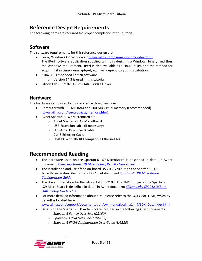
Reference Design Requirements The following items are required for proper completion of this tutorial.
Software The software requirements for this reference design are:
Linux, Windows XP, Windows 7 (www.xilinx.com/ise/ossupport/index.htm) The IPerf software application supplied with this design is a Windows binary, and thus the Windows requirement. IPerf is also available as a Linux utility, and the method for acquiring it in Linux (yum, apt-get, etc.) will depend on your distribution.
Xilinx IDS Embedded Edition software o Version 14.3 is used in this tutorial
Silicon Labs CP2102 USB-to-UART Bridge Driver
Hardware The hardware setup used by this reference design includes:
Computer with 500 MB RAM and 500 MB virtual memory (recommended) (www.xilinx.com/ise/products/memory.htm)
Avnet Spartan-6 LX9 MicroBoard Kit o Avnet Spartan-6 LX9 MicroBoard o USB Extension cable (if necessary) o USB-A to USB-micro B cable o Cat-5 Ethernet Cable o Host PC with 10/100 compatible Ethernet NIC
Recommended Reading The hardware used on the Spartan-6 LX9 MicroBoard is described in detail in Avnet
document Xilinx Spartan-6 LX9 MicroBoard, Rev. B - User Guide.
The installation and use of the on-board USB JTAG circuit on the Spartan-6 LX9 MicroBoard is described in detail in Avnet document Spartan-6 LX9 MicroBoard Configuration Guide.
The driver installation for the Silicon Labs CP2102 USB-UART bridge on the Spartan-6 LX9 MicroBoard is described in detail in Avnet document Silicon Labs CP201x USB-to-UART Setup Guide v.1.1.
For more detailed information about SDK, please refer to the SDK Help HTML, which by default is located here: www.xilinx.com/support/documentation/sw_manuals/xilinx14_4/SDK_Doc/index.html
Details on the Spartan-6 FPGA family are included in the following Xilinx documents: o Spartan-6 Family Overview (DS160) o Spartan-6 FPGA Data Sheet (DS162) o Spartan-6 FPGA Configuration User Guide (UG380)

Spartan-6 LX9 MicroBoard Tutorial
Page 6 of 65
Supplied Files The following directory structure is included with this reference design: demo: Contains the files to run receive test program:
bootloop.bit: The golden FPGA bitstream of the hardware design required to run the lwIP raw mode networking applications. cp_from_sdk.bat: Batch file to copy hardware bitstream and software executables from the SDK workspace demo_raw_apps.bat: Batch file to run the commands to load the FPGA bitstream of the hardware design, download the webserver file system, and download the software application. download.cmd: Xilinx iMPACT command file to load the FPGA bitstream. image.mfs: Formatted webserver filesystem. mbrst.opt: XMD options file to reset the MicroBlaze and re-download the software executable without downloading the webserver file system. raw_apps.elf: The golden MicroBlaze executable for the lwIP raw mode applications.
run_iperf_cli.bat: Batch script to run IPerf in client mode with RxTest. run_iperf_ser.bat: Batch script to run IPerf in server mode with TxTest. sleep.exe: Utility to pause execution of the batch file. xmd.ini: Command file used by XMD to download the webserver file system and start execution of the lwIP raw mode software applications.
IPerf: Contains the Internet Performance program to run on a windows PC iperf.exe: Internet Performance executable for Windows. memfs: Collection of files for the webserver filesystem SDK_sw: Contains the software applications source files. xps: Empty folder to use to create new XPS hardware project for this design. SDK_Workspace: Empty folder to use to create new SDK workspace for this design. xps_solution.zip: Contains pre-built XPS project for this design sdk_solution.zip: Contains pre-built SDK project for this design AvtS6LX9MicroBoard_SW201_lwIP_Apps_14_4_01.pdf: This document.
Spartan-6 LX9 MicroBoard Tutorial
Page 7 of 65
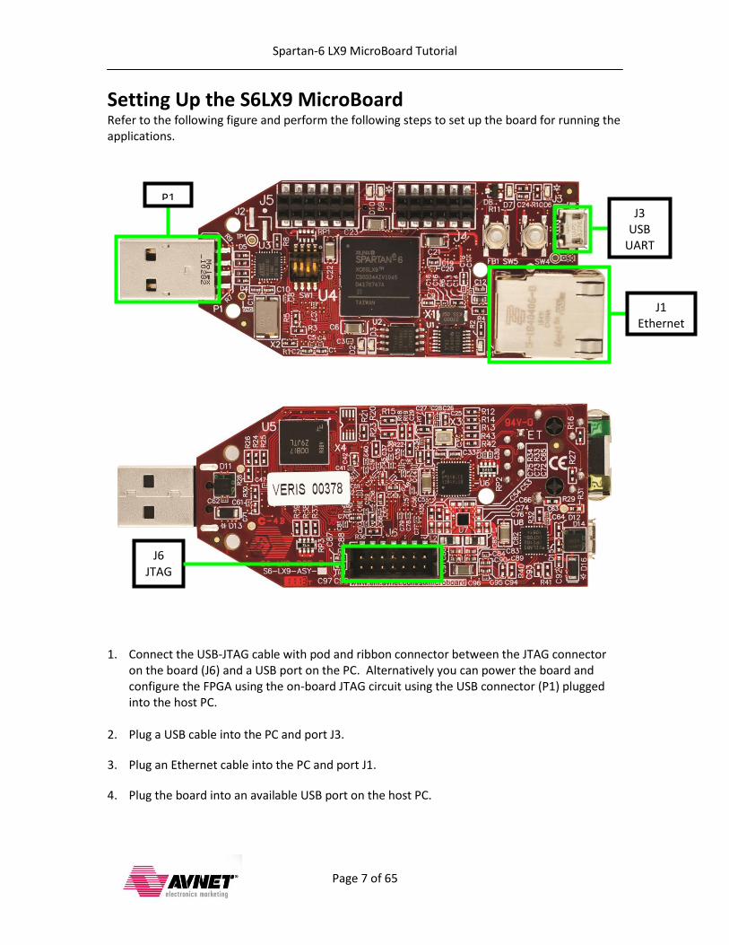
Setting Up the S6LX9 MicroBoard Refer to the following figure and perform the following steps to set up the board for running the applications.
1. Connect the USB-JTAG cable with pod and ribbon connector between the JTAG connector on the board (J6) and a USB port on the PC. Alternatively you can power the board and configure the FPGA using the on-board JTAG circuit using the USB connector (P1) plugged into the host PC.
2. Plug a USB cable into the PC and port J3.
3. Plug an Ethernet cable into the PC and port J1.
4. Plug the board into an available USB port on the host PC.
J3 USB
UART
P1
J1 Ethernet
J6 JTAG
Spartan-6 LX9 MicroBoard Tutorial
Page 8 of 65
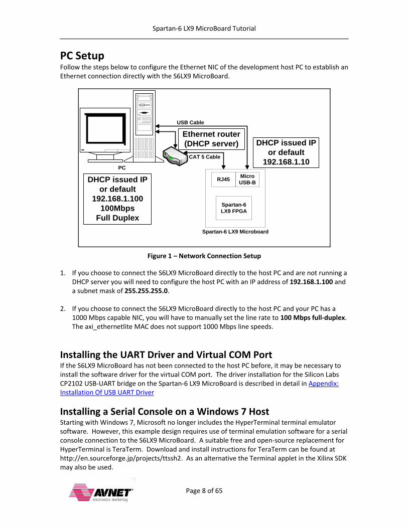
PC Setup Follow the steps below to configure the Ethernet NIC of the development host PC to establish an Ethernet connection directly with the S6LX9 MicroBoard.
PC
Micro
USB-B
Spartan-6 LX9 Microboard
Spartan-6
LX9 FPGA
DHCP issued IP
or default
192.168.1.100
100Mbps
Full Duplex
DHCP issued IP
or default
192.168.1.10
RJ45
USB Cable
CAT 5 Cable
Ethernet router
(DHCP server)
Figure 1 – Network Connection Setup
1. If you choose to connect the S6LX9 MicroBoard directly to the host PC and are not running a DHCP server you will need to configure the host PC with an IP address of 192.168.1.100 and a subnet mask of 255.255.255.0.
2. If you choose to connect the S6LX9 MicroBoard directly to the host PC and your PC has a 1000 Mbps capable NIC, you will have to manually set the line rate to 100 Mbps full-duplex. The axi_ethernetlite MAC does not support 1000 Mbps line speeds.
Installing the UART Driver and Virtual COM Port If the S6LX9 MicroBoard has not been connected to the host PC before, it may be necessary to install the software driver for the virtual COM port. The driver installation for the Silicon Labs CP2102 USB-UART bridge on the Spartan-6 LX9 MicroBoard is described in detail in Appendix: Installation Of USB UART Driver
Installing a Serial Console on a Windows 7 Host Starting with Windows 7, Microsoft no longer includes the HyperTerminal terminal emulator software. However, this example design requires use of terminal emulation software for a serial console connection to the S6LX9 MicroBoard. A suitable free and open-source replacement for HyperTerminal is TeraTerm. Download and install instructions for TeraTerm can be found at http://en.sourceforge.jp/projects/ttssh2. As an alternative the Terminal applet in the Xilinx SDK may also be used.
Spartan-6 LX9 MicroBoard Tutorial
Page 9 of 65
Running the Demo Files
You can load the FPGA and run the test applications without building the design by using the demo scripts and the pre-built bitstream and elf files. You must have the Xilinx tools installed on your host, and have the hardware set up and connected as per the previous steps.
Applications Download 1. Start a serial terminal session and set the serial port parameters to 9600 baud rate, no
parity, 8 bits, 1 stop bit and no flow control.
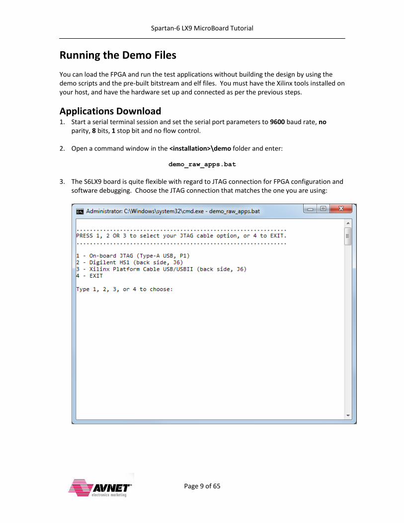
2. Open a command window in the <installation>\demo folder and enter:
demo_raw_apps.bat
3. The S6LX9 board is quite flexible with regard to JTAG connection for FPGA configuration and
software debugging. Choose the JTAG connection that matches the one you are using:
Spartan-6 LX9 MicroBoard Tutorial
Page 10 of 65
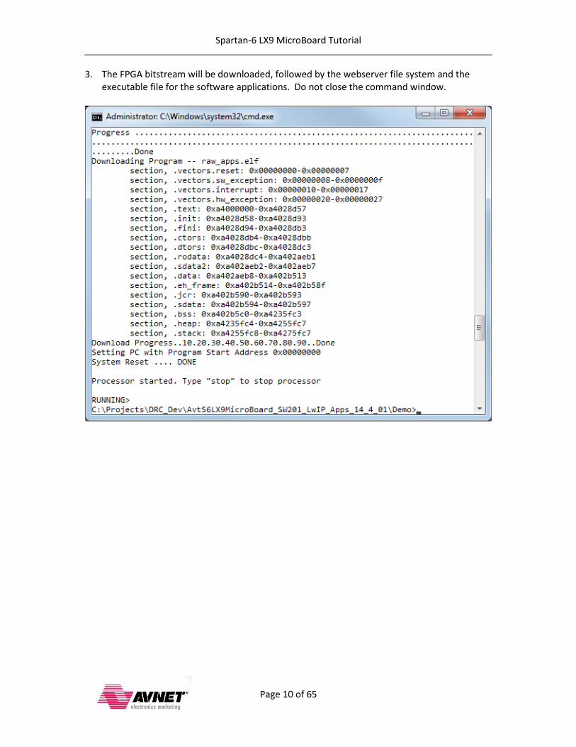
3. The FPGA bitstream will be downloaded, followed by the webserver file system and the executable file for the software applications. Do not close the command window.

Spartan-6 LX9 MicroBoard Tutorial
Page 11 of 65
4. When the executable has finished loading and is ready to run you should see the following in your serial terminal window: a. At startup lwIP is configured to fetch an IP address from a DHCP server. If there is no
DHCP server present the DHCP request will timeout and the board will default to an IP address of 192.168.1.10:
b. If a DHCP server is found, a dynamic IP address will be assigned:
Spartan-6 LX9 MicroBoard Tutorial
Page 12 of 65
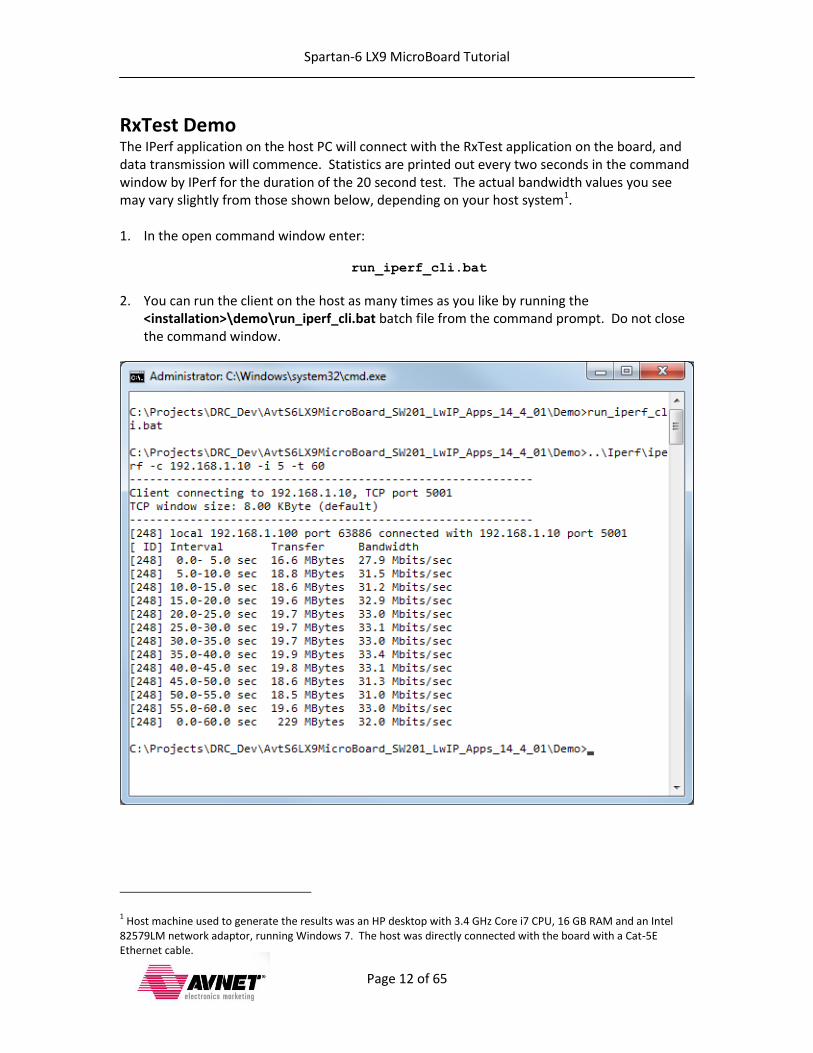
RxTest Demo The IPerf application on the host PC will connect with the RxTest application on the board, and data transmission will commence. Statistics are printed out every two seconds in the command window by IPerf for the duration of the 20 second test. The actual bandwidth values you see may vary slightly from those shown below, depending on your host system1. 1. In the open command window enter:
run_iperf_cli.bat
2. You can run the client on the host as many times as you like by running the <installation>\demo\run_iperf_cli.bat batch file from the command prompt. Do not close the command window.
1 Host machine used to generate the results was an HP desktop with 3.4 GHz Core i7 CPU, 16 GB RAM and an Intel
82579LM network adaptor, running Windows 7. The host was directly connected with the board with a Cat-5E Ethernet cable.
Spartan-6 LX9 MicroBoard Tutorial
Page 13 of 65
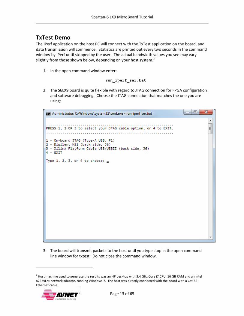
TxTest Demo The IPerf application on the host PC will connect with the TxTest application on the board, and data transmission will commence. Statistics are printed out every two seconds in the command window by IPerf until stopped by the user. The actual bandwidth values you see may vary slightly from those shown below, depending on your host system.2
1. In the open command window enter:
run_iperf_ser.bat
2. The S6LX9 board is quite flexible with regard to JTAG connection for FPGA configuration and software debugging. Choose the JTAG connection that matches the one you are using:
3. The board will transmit packets to the host until you type stop in the open command
line window for txtest. Do not close the command window.
2 Host machine used to generate the results was an HP desktop with 3.4 GHz Core i7 CPU, 16 GB RAM and an Intel
82579LM network adaptor, running Windows 7. The host was directly connected with the board with a Cat-5E Ethernet cable.
Spartan-6 LX9 MicroBoard Tutorial
Page 14 of 65
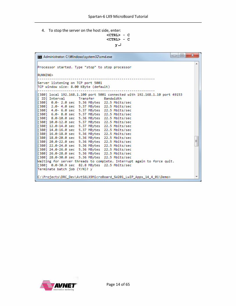
4. To stop the server on the host side, enter: <CTRL> - C
<CTRL> - C
y
Spartan-6 LX9 MicroBoard Tutorial
Page 15 of 65
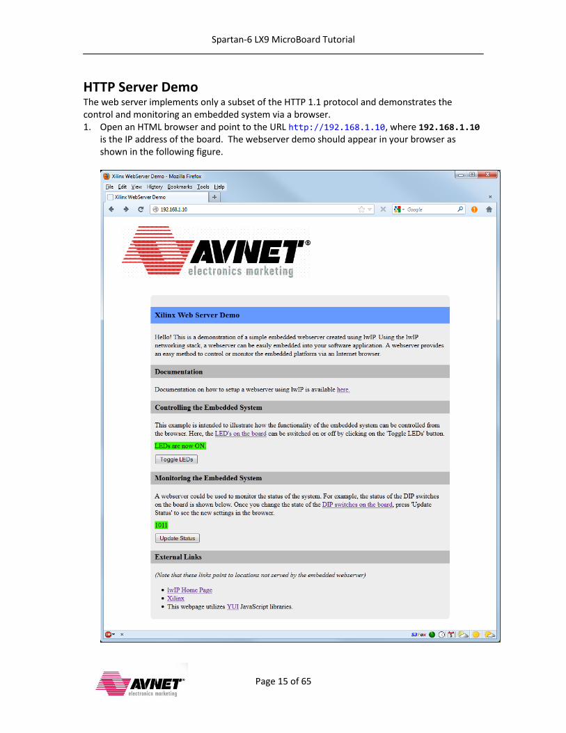
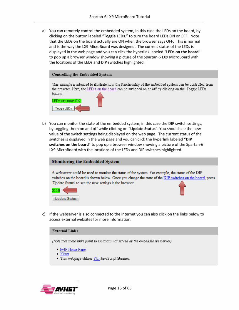
HTTP Server Demo The web server implements only a subset of the HTTP 1.1 protocol and demonstrates the control and monitoring an embedded system via a browser. 1. Open an HTML browser and point to the URL http://192.168.1.10, where 192.168.1.10
is the IP address of the board. The webserver demo should appear in your browser as shown in the following figure.
Spartan-6 LX9 MicroBoard Tutorial
Page 16 of 65
a) You can remotely control the embedded system, in this case the LEDs on the board, by clicking on the button labeled “Toggle LEDs.” to turn the board LEDs ON or OFF. Note that the LEDs on the board actually are ON when the browser says OFF. This is normal and is the way the LX9 MicroBoard was designed. The current status of the LEDs is displayed in the web page and you can click the hyperlink labeled “LEDs on the board” to pop up a browser window showing a picture of the Spartan-6 LX9 MicroBoard with the locations of the LEDs and DIP switches highlighted.
b) You can monitor the state of the embedded system, in this case the DIP switch settings, by toggling them on and off while clicking on “Update Status”. You should see the new value of the switch settings being displayed on the web page. The current status of the switches is displayed in the web page and you can click the hyperlink labeled “DIP switches on the board” to pop up a browser window showing a picture of the Spartan-6 LX9 MicroBoard with the locations of the LEDs and DIP switches highlighted.
c) If the webserver is also connected to the internet you can also click on the links below to access external websites for more information.
Spartan-6 LX9 MicroBoard Tutorial
Page 17 of 65
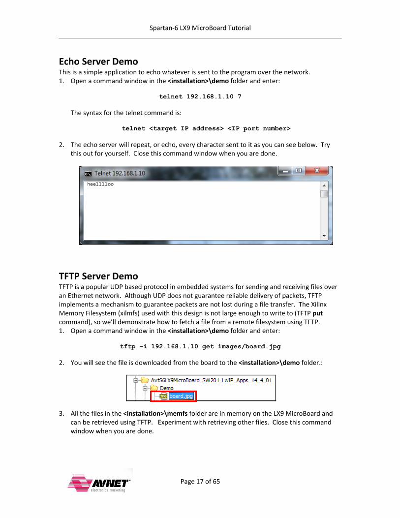
Echo Server Demo This is a simple application to echo whatever is sent to the program over the network. 1. Open a command window in the <installation>\demo folder and enter:
telnet 192.168.1.10 7
The syntax for the telnet command is:
telnet <target IP address> <IP port number>
2. The echo server will repeat, or echo, every character sent to it as you can see below. Try this out for yourself. Close this command window when you are done.
TFTP Server Demo TFTP is a popular UDP based protocol in embedded systems for sending and receiving files over an Ethernet network. Although UDP does not guarantee reliable delivery of packets, TFTP implements a mechanism to guarantee packets are not lost during a file transfer. The Xilinx Memory Filesystem (xilmfs) used with this design is not large enough to write to (TFTP put command), so we’ll demonstrate how to fetch a file from a remote filesystem using TFTP. 1. Open a command window in the <installation>\demo folder and enter:
tftp -i 192.168.1.10 get images/board.jpg
2. You will see the file is downloaded from the board to the <installation>\demo folder.:
3. All the files in the <installation>\memfs folder are in memory on the LX9 MicroBoard and can be retrieved using TFTP. Experiment with retrieving other files. Close this command window when you are done.
Spartan-6 LX9 MicroBoard Tutorial
Page 18 of 65
Creating the MicroBlaze System
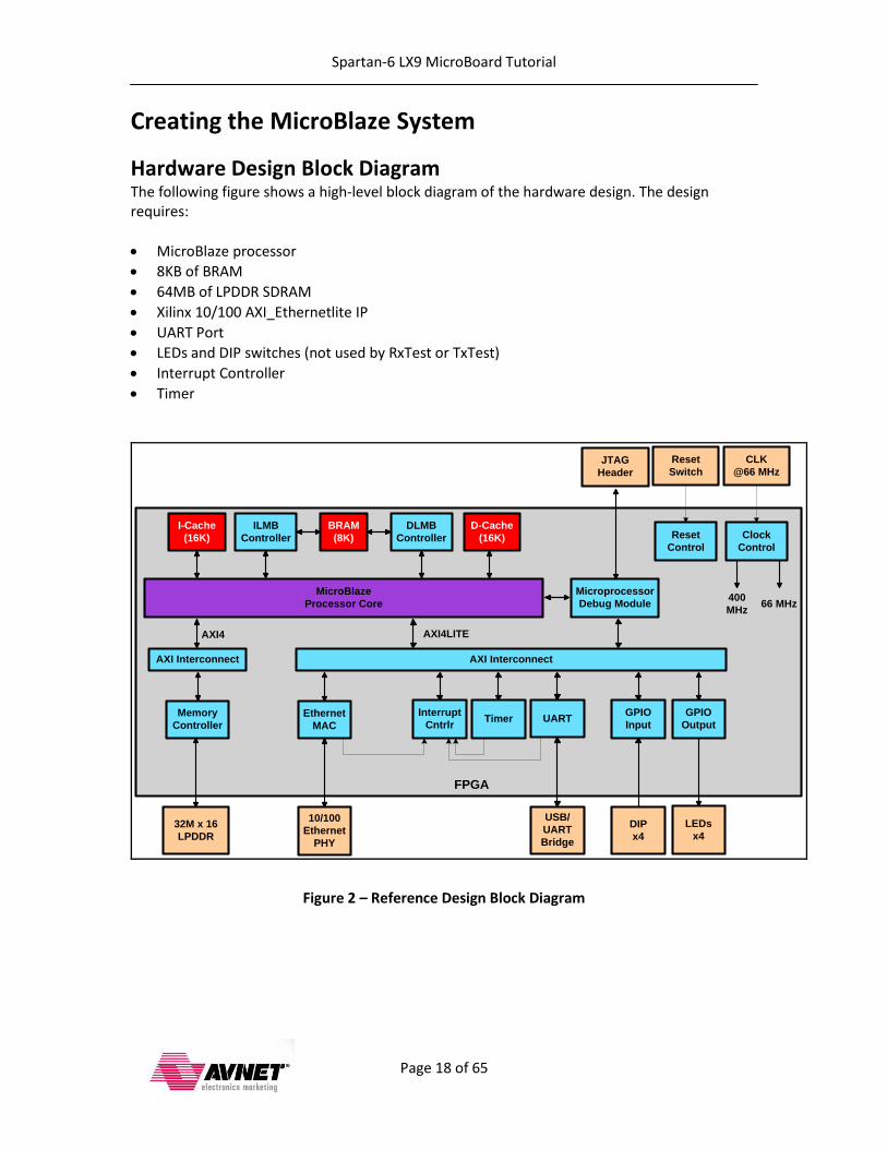
Hardware Design Block Diagram The following figure shows a high-level block diagram of the hardware design. The design requires:
MicroBlaze processor
8KB of BRAM
64MB of LPDDR SDRAM
Xilinx 10/100 AXI_Ethernetlite IP
UART Port
LEDs and DIP switches (not used by RxTest or TxTest)
Interrupt Controller
Timer
FPGA
JTAG
Header
MicroBlaze
Processor Core
GPIO
Output
GPIO
Input
LEDs
x4DIP
x4
BRAM
(8K)
Memory
Controller
Microprocessor
Debug Module
DLMB
Controller
ILMB
Controller
32M x 16
LPDDR
CLK
@66 MHz
Clock
Control
Reset
Switch
Reset
Control
TimerInterrupt
Cntrlr
400
MHz
I-Cache
(16K)
D-Cache
(16K)
UART
USB/
UART
Bridge
66 MHz
AXI4LITE
AXI Interconnect AXI Interconnect
AXI4
Ethernet
MAC
10/100
Ethernet
PHY
Figure 2 – Reference Design Block Diagram

Spartan-6 LX9 MicroBoard Tutorial
Page 19 of 65
Description of XPS Hardware Modifications This design was created using a standard Base System Builder flow with the following modifications:
MicroBlaze processor settings: o System clock set to 66MHz o Enable the barrel shifter in the MicroBlaze processor o Enable the integer divider o Specify 16KB for instruction and data cache for the MicroBlaze processor o Specify 8KB for local memory size o Configure the i-cache and d-cache with an 8 word cache line o Select area (size) optimized MicroBlaze
AXI_Ethernetlite MAC settings o Enable the interrupt o Enable second Rx and Tx buffers
Other settings o Enable the interrupt for the axi_uartlite o Add a axi_timer with interrupt
Spartan-6 LX9 MicroBoard Tutorial
Page 20 of 65
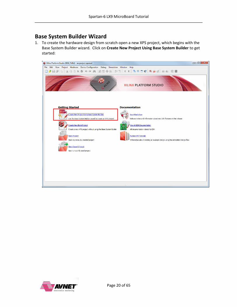
Base System Builder Wizard 1. To create the hardware design from scratch open a new XPS project, which begins with the
Base System Builder wizard. Click on Create New Project Using Base System Builder to get started:
Spartan-6 LX9 MicroBoard Tutorial
Page 21 of 65
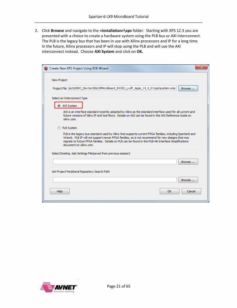
2. Click Browse and navigate to the <installation>\xps folder. Starting with XPS 12.3 you are presented with a choice to create a hardware system using the PLB bus or AXI interconnect. The PLB is the legacy bus that has been in use with Xilinx processors and IP for a long time. In the future, Xilinx processors and IP will stop using the PLB and will use the AXI interconnect instead. Choose AXI System and click on OK.
Spartan-6 LX9 MicroBoard Tutorial
Page 22 of 65
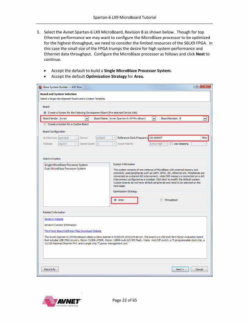
3. Select the Avnet Spartan-6 LX9 MicroBoard, Revision B as shown below. Though for top Ethernet performance we may want to configure the MicroBlaze processor to be optimized for the highest throughput, we need to consider the limited resources of the S6LX9 FPGA. In this case the small size of the FPGA trumps the desire for high system performance and Ethernet data throughput. Configure the MicroBlaze processor as follows and click Next to continue.
Accept the default to build a Single MicroBlaze Processor System.
Accept the default Optimization Strategy for Area.

Spartan-6 LX9 MicroBoard Tutorial
Page 23 of 65
4. Customize the Processor, Cache and Peripheral Configuration. a. Configure the processor and cache settings as follows. Do not click Finish yet:
Change the Processor Frequency to 66MHz
Select 16KB for Instruction and Data Cache Size
Accept the default of 8KB for Local Memory Size.
Use the Add and Remove buttons to add and remove the peripherals shown below. o Remove the CDCE913_I2C peripheral o Remove the SPI_FLASH peripheral o Add a axi_timer peripheral
Spartan-6 LX9 MicroBoard Tutorial
Page 24 of 65
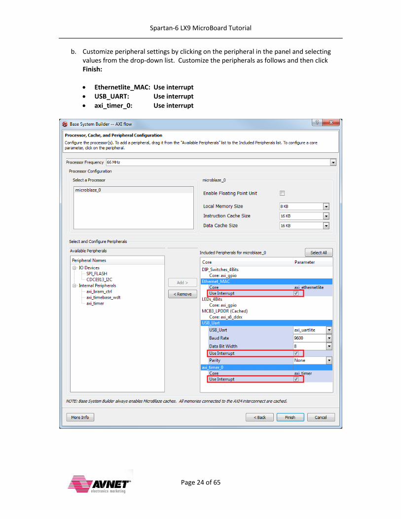
b. Customize peripheral settings by clicking on the peripheral in the panel and selecting values from the drop-down list. Customize the peripherals as follows and then click Finish:
Ethernetlite_MAC: Use interrupt
USB_UART: Use interrupt
axi_timer_0: Use interrupt
Spartan-6 LX9 MicroBoard Tutorial
Page 25 of 65
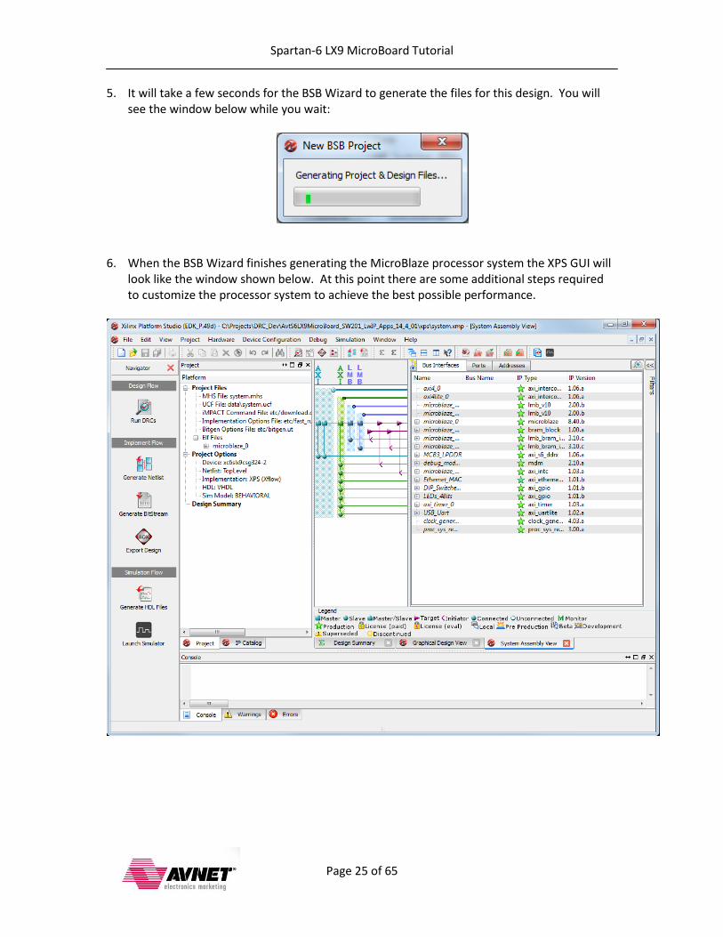
5. It will take a few seconds for the BSB Wizard to generate the files for this design. You will see the window below while you wait:
6. When the BSB Wizard finishes generating the MicroBlaze processor system the XPS GUI will
look like the window shown below. At this point there are some additional steps required to customize the processor system to achieve the best possible performance.
Spartan-6 LX9 MicroBoard Tutorial
Page 26 of 65
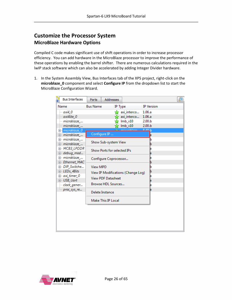
Customize the Processor System MicroBlaze Hardware Options
Compiled C code makes significant use of shift operations in order to increase processor efficiency. You can add hardware in the MicroBlaze processor to improve the performance of these operations by enabling the barrel shifter. There are numerous calculations required in the lwIP stack software which can also be accelerated by adding Integer Divider hardware. 1. In the System Assembly View, Bus Interfaces tab of the XPS project, right-click on the
microblaze_0 component and select Configure IP from the dropdown list to start the MicroBlaze Configuration Wizard.

Spartan-6 LX9 MicroBoard Tutorial
Page 27 of 65
2. Verify the Select implementation to optimize area is selected and accept the remaining defaults on the first Configuration Wizard screen and click Next:
Spartan-6 LX9 MicroBoard Tutorial
Page 28 of 65
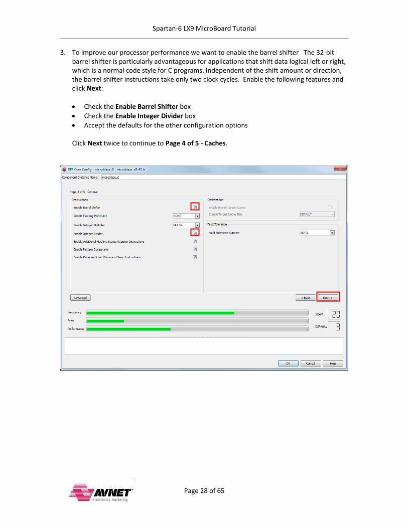
3. To improve our processor performance we want to enable the barrel shifter The 32-bit barrel shifter is particularly advantageous for applications that shift data logical left or right, which is a normal code style for C programs. Independent of the shift amount or direction, the barrel shifter instructions take only two clock cycles. Enable the following features and click Next:
Check the Enable Barrel Shifter box
Check the Enable Integer Divider box
Accept the defaults for the other configuration options Click Next twice to continue to Page 4 of 5 - Caches.
Spartan-6 LX9 MicroBoard Tutorial
Page 29 of 65
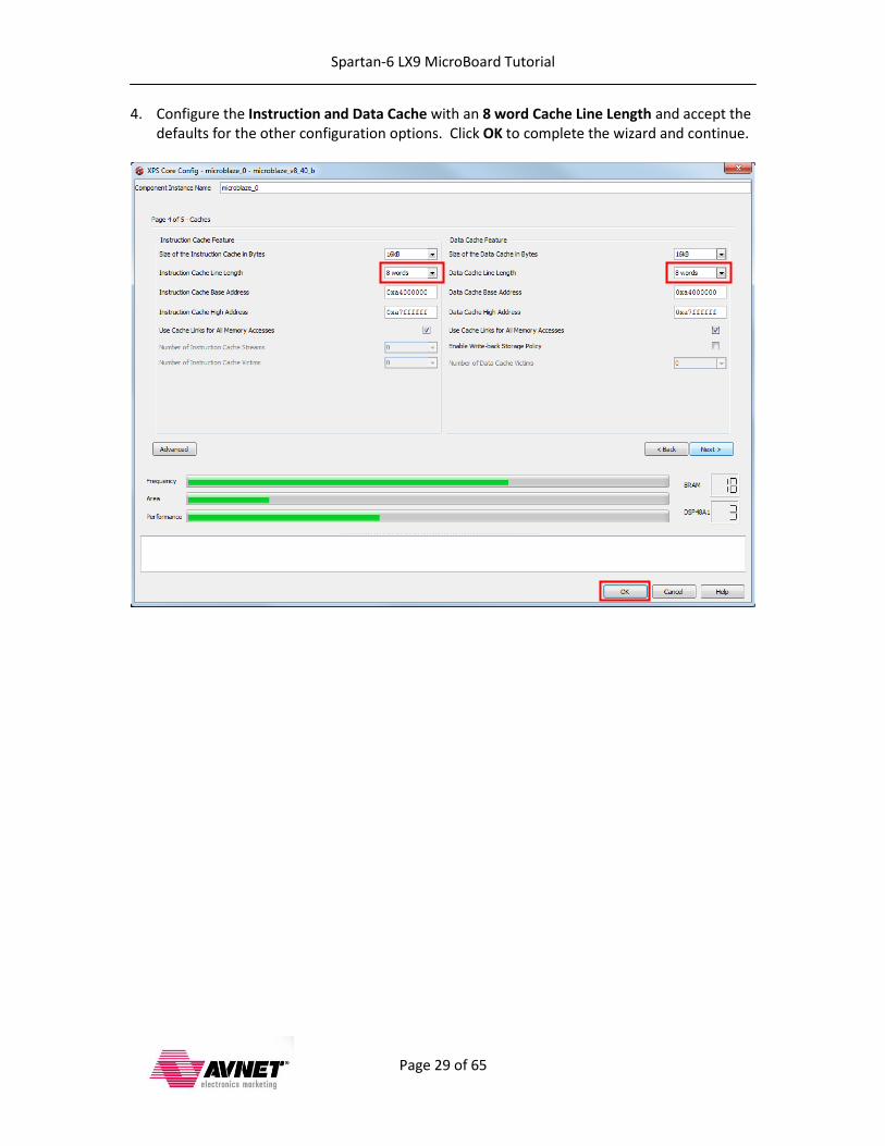
4. Configure the Instruction and Data Cache with an 8 word Cache Line Length and accept the defaults for the other configuration options. Click OK to complete the wizard and continue.
Spartan-6 LX9 MicroBoard Tutorial
Page 30 of 65
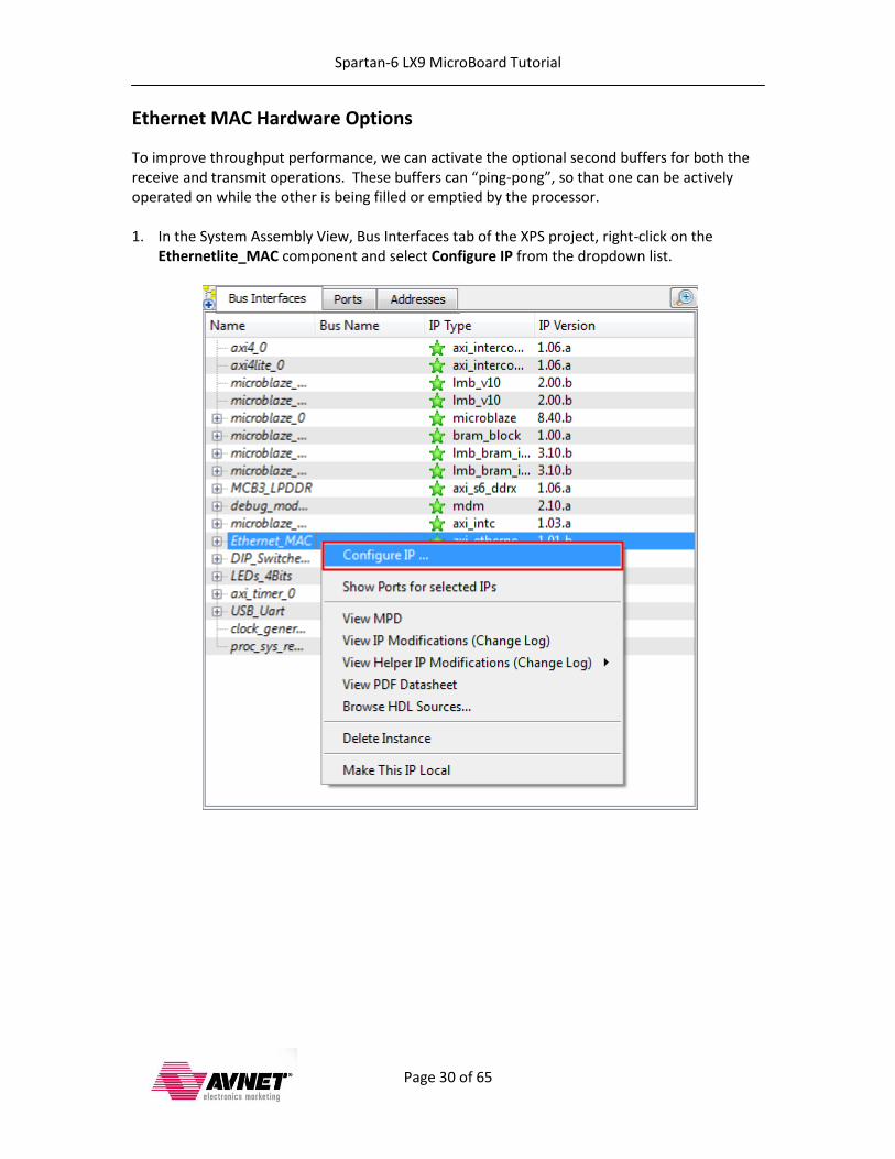
Ethernet MAC Hardware Options
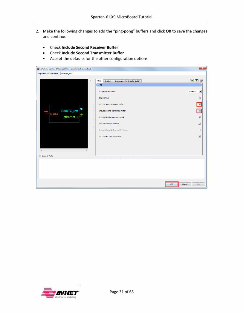
To improve throughput performance, we can activate the optional second buffers for both the receive and transmit operations. These buffers can “ping-pong”, so that one can be actively operated on while the other is being filled or emptied by the processor. 1. In the System Assembly View, Bus Interfaces tab of the XPS project, right-click on the
Ethernetlite_MAC component and select Configure IP from the dropdown list.
Spartan-6 LX9 MicroBoard Tutorial
Page 31 of 65
2. Make the following changes to add the “ping-pong” buffers and click OK to save the changes and continue.
Check Include Second Receiver Buffer
Check Include Second Transmitter Buffer
Accept the defaults for the other configuration options

Spartan-6 LX9 MicroBoard Tutorial
Page 32 of 65
Modify the Bitstream Settings
Default behavior of the bitstream generation tool is to create an internal pulldown on all unused pins. Unfortunately this causes a problem with the DDR3 memory interface and prevents the design from working. Follow the steps below to edit the bitstream generation options to allow unused pins to float. 1. In the XPS Project pane open the Project Files node and double-click to open the bitgen.ut
file:
Spartan-6 LX9 MicroBoard Tutorial
Page 33 of 65
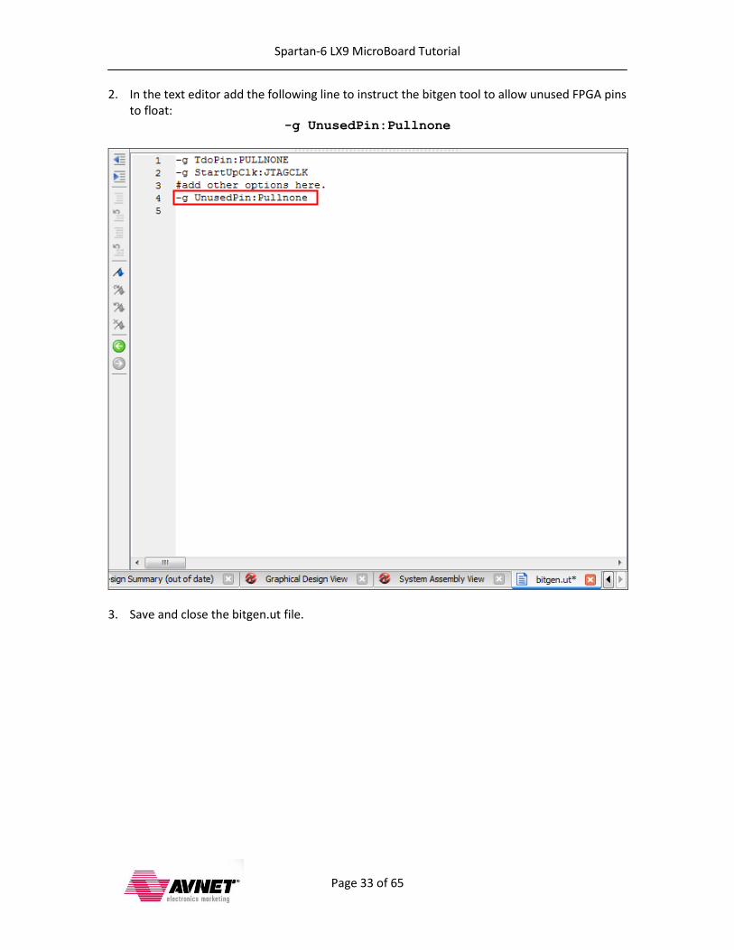
2. In the text editor add the following line to instruct the bitgen tool to allow unused FPGA pins to float:
-g UnusedPin:Pullnone
3. Save and close the bitgen.ut file.

Spartan-6 LX9 MicroBoard Tutorial
Page 34 of 65
Implement the Hardware Design 1. Select Hardware Generate Bitstream from the XPS GUI to build the design. You can also
click on in the Navigator panel of the XPS GUI.
2. Start a serial terminal session using your terminal software of choice and set the serial port parameters to 9600 baud rate, no parity, 8 bits, 1 stop bit and no flow control.
Spartan-6 LX9 MicroBoard Tutorial
Page 35 of 65
Create the SDK Workspace
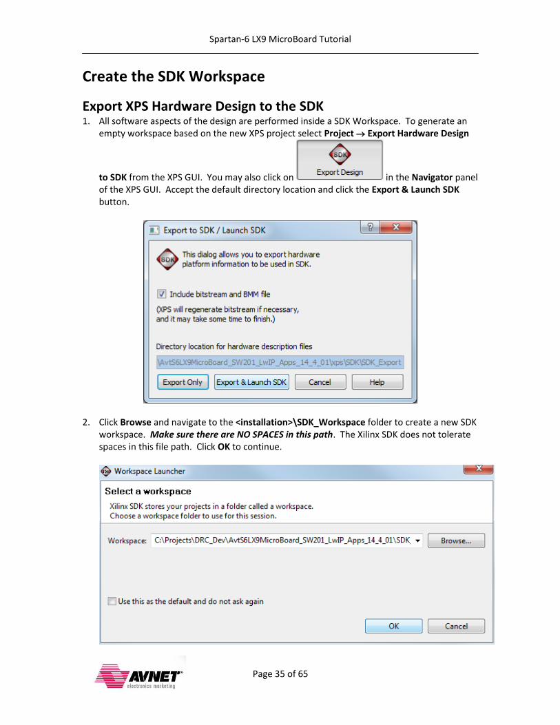
Export XPS Hardware Design to the SDK 1. All software aspects of the design are performed inside a SDK Workspace. To generate an
empty workspace based on the new XPS project select Project Export Hardware Design
to SDK from the XPS GUI. You may also click on in the Navigator panel of the XPS GUI. Accept the default directory location and click the Export & Launch SDK button.
2. Click Browse and navigate to the <installation>\SDK_Workspace folder to create a new SDK workspace. Make sure there are NO SPACES in this path. The Xilinx SDK does not tolerate spaces in this file path. Click OK to continue.
Spartan-6 LX9 MicroBoard Tutorial
Page 36 of 65
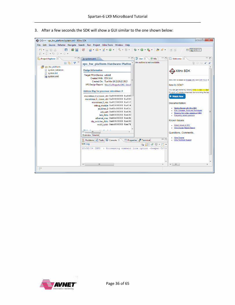
3. After a few seconds the SDK will show a GUI similar to the one shown below:
Spartan-6 LX9 MicroBoard Tutorial
Page 37 of 65
Description of SDK Software BSP and Linker Modifications The Xilinx Software Development Kit (SDK) is used for all software tasks. The software platform settings were modified from the default settings as follows:
lwip library is generated o TEMAC adapter option n_tx_descriptors is set to 256 o TEMAC adapter option n_rx_descriptors is set to 256 o TEMAC adapter option phy_link_speed is set to CONFIG_LINKSPEED100 o lwIP memory option memp_n_pbuf is set to 1024 o lwIP memory option memp_n_tcp_seg is set to 1024 o Pbuf option pbuf_pool_size is set to 1024 o TCP option tcp_wnd is set to 4096 o TCP option tcp_mss is set to 1450 o DHCP option lwip_dhcp is set to true
xilmfs library is generated o numbytes is set to 2048000 o base_address is set to 0xA9000000 o init_type is set to MFSINIT_IMAGE o need_utils parameter is set to true
Custom linker script o All code sections reside in LPDDR o Heap and Stack reside in LPDDR o Stack Size and Heap Size are both set to x20000 (128KB)
Application uses the lwIP and xilmfs software libraries.
Spartan-6 LX9 MicroBoard Tutorial
Page 38 of 65
Create and Modify the Board Support Package The first thing to create in our empty workspace is a Board Support Package (BSP) on which individual projects can be built. Multiple BSPs and multiple application projects can be held in a single SDK workspace.
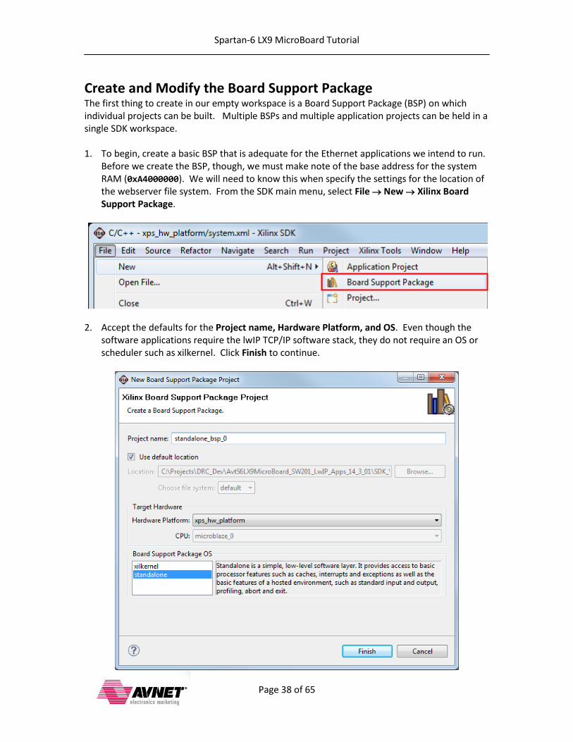
1. To begin, create a basic BSP that is adequate for the Ethernet applications we intend to run.
Before we create the BSP, though, we must make note of the base address for the system RAM (0xA4000000). We will need to know this when specify the settings for the location of the webserver file system. From the SDK main menu, select File New Xilinx Board Support Package.
2. Accept the defaults for the Project name, Hardware Platform, and OS. Even though the
software applications require the lwIP TCP/IP software stack, they do not require an OS or scheduler such as xilkernel. Click Finish to continue.
Spartan-6 LX9 MicroBoard Tutorial
Page 39 of 65
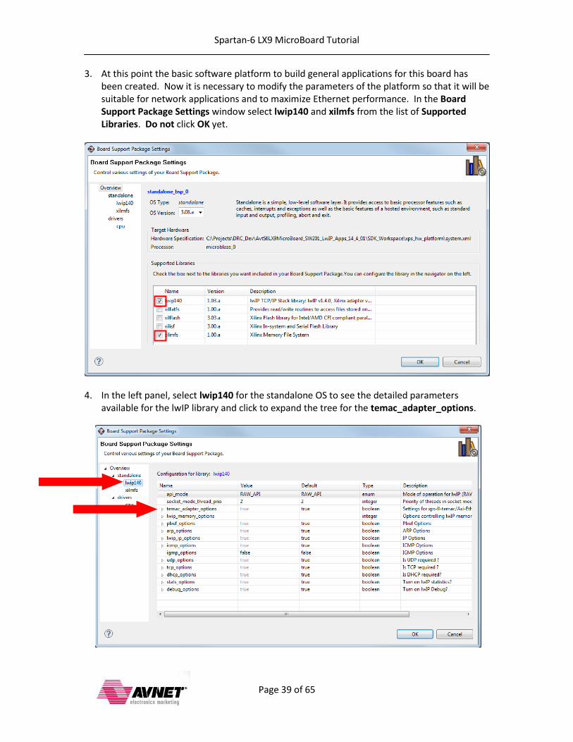
3. At this point the basic software platform to build general applications for this board has been created. Now it is necessary to modify the parameters of the platform so that it will be suitable for network applications and to maximize Ethernet performance. In the Board Support Package Settings window select lwip140 and xilmfs from the list of Supported Libraries. Do not click OK yet.
4. In the left panel, select lwip140 for the standalone OS to see the detailed parameters
available for the lwIP library and click to expand the tree for the temac_adapter_options.

Spartan-6 LX9 MicroBoard Tutorial
Page 40 of 65
5. To maximize Ethernet throughput it is necessary to increase the number of Tx and Rx descriptors to be used. The optimal value for the number of n_tx_descriptors and n_rx_descriptors for this example design is 256. We also need to set the phy_link_speed to CONFIG_LINKSPEED100. Normally it would be desirable to leave this set for auto-negotiation, but this setting is PHY dependent and has only been tested with Marvell PHYs used on Xilinx development boards. The maximum throughput of the axi_ethernetlite peripheral is 100Mbps, so we set the link speed to 100Mbps here. This setting must be correct and must match the capabilities of the Ethernet MAC and PHY in order to transmit and receive packets. Do not click OK yet.
6. Click to expand the tree for the lwip_memory_options:

Spartan-6 LX9 MicroBoard Tutorial
Page 41 of 65
7. Our webserver file system is essentially a large ROM because it resides in system DDR3 memory and serves a few files while also allowing us to monitor the status of board GPIO. To maximize this file serving performance we need to set the number of memp_n_pbuf and memp_n_tcp_seg to 1024. Do not click OK yet.
8. Click to expand the tree for the pbuf_options:

Spartan-6 LX9 MicroBoard Tutorial
Page 42 of 65
9. Packet buffers (Pbufs) carry packets across various layers of the TCP/IP stack. To increase our Ethernet performance we need to increase the pbuf_pool_size to 1024. Do not click OK yet.
10. Click to expand the tree for the tcp_options:

Spartan-6 LX9 MicroBoard Tutorial
Page 43 of 65
11. To maximize the use of the hardware Rx ping-pong buffers it is necessary to increase the size of the TCP window. A standard Ethernet frame is 1518 bytes long, so each buffer can hold a single frame. By default, the receive window is set at 2048 bytes, meaning only one frame can be in transit before an acknowledgement is sent to the host. We can double the size of tcp_wnd to 4096 bytes to allow a second frame in transit, which will better utilize the available bandwidth. Experiment with this parameter to see how higher and lower values affect the throughput on your system. Do not click OK yet.
12. To maximize the Tx throughput it is necessary to make the maximum segment size slightly smaller than the default. The maximum segment size controls the amount of payload bytes per IP packet. Ideally this value is as large as possible to maximize the transmit efficiency. For this MicroBlaze system connected over Ethernet to a Windows host computer, the best transmit throughput was achieved with a tcp_mss value of 1450 bytes. Experiment with this parameter to see how higher and lower values affect the throughput on your system. Do not click OK yet.
Spartan-6 LX9 MicroBoard Tutorial
Page 44 of 65
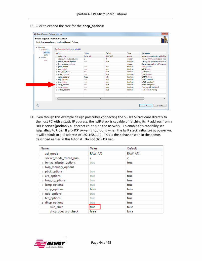
13. Click to expand the tree for the dhcp_options:
14. Even though this example design prescribes connecting the S6LX9 MicroBoard directly to the host PC with a static IP address, the lwIP stack is capable of fetching its IP address from a DHCP server (probably a Ethernet router) on the network. To enable this capability set lwip_dhcp to true. If a DHCP server is not found when the lwIP stack initializes at power on, it will default to a IP address of 192.168.1.10. This is the behavior seen in the demos described earlier in this tutorial. Do not click OK yet.

Spartan-6 LX9 MicroBoard Tutorial
Page 45 of 65
15. In the left panel, select xilmfs for the standalone OS to see the detailed parameters available for the xilmfs library.
16. In this window specify the following settings:
Set numbytes to 2048000
Set base_address to 0xA5000000. Remember that we noted this earlier. This is the base address of the system RAM plus an offset above and beyond where the application code is located.
Set init_type to MFSINIT_IMAGE
Set need_utils to true
Click OK to save the changes, and the software platform will automatically compile and link.
Spartan-6 LX9 MicroBoard Tutorial
Page 46 of 65
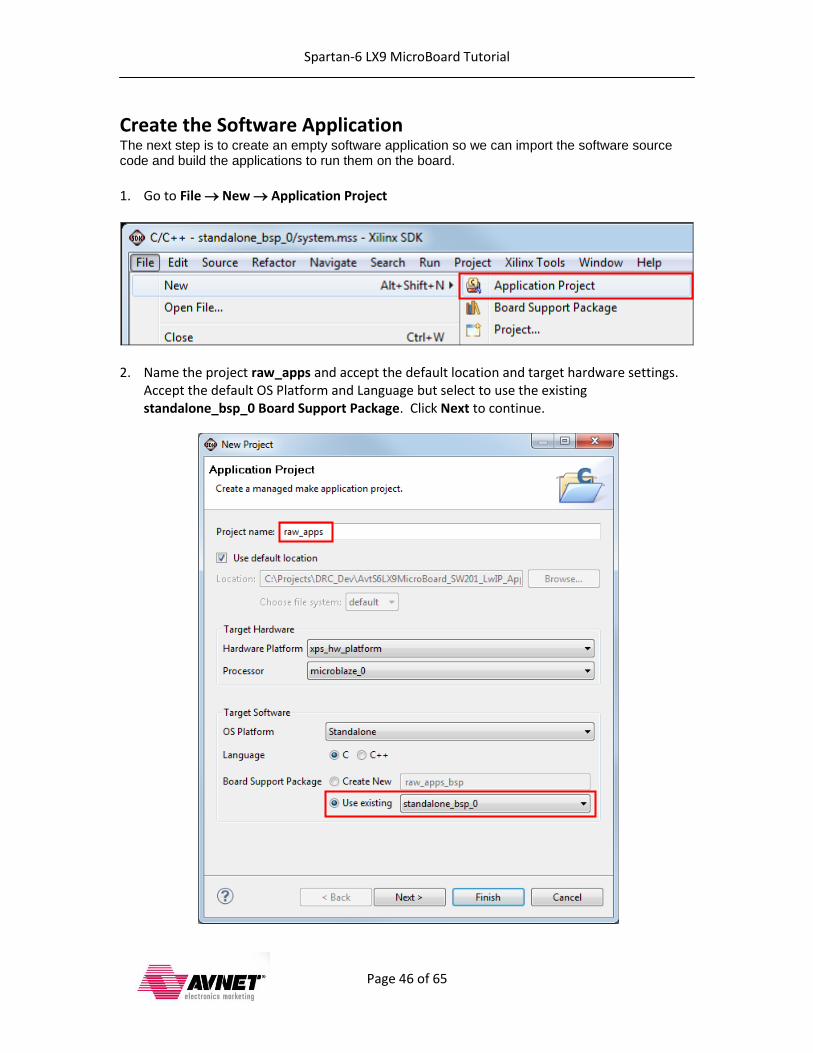
Create the Software Application The next step is to create an empty software application so we can import the software source code and build the applications to run them on the board.
1. Go to File New Application Project
2. Name the project raw_apps and accept the default location and target hardware settings. Accept the default OS Platform and Language but select to use the existing standalone_bsp_0 Board Support Package. Click Next to continue.
Spartan-6 LX9 MicroBoard Tutorial
Page 47 of 65
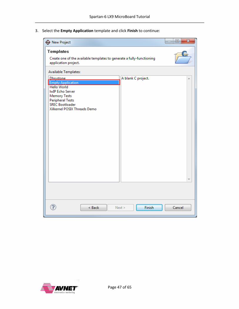
3. Select the Empty Application template and click Finish to continue:

Spartan-6 LX9 MicroBoard Tutorial
Page 48 of 65
4. Next step is to import the source code. Open the raw_apps application node in the Project Explorer pane and right-click on the src folder and select Import…
Spartan-6 LX9 MicroBoard Tutorial
Page 49 of 65
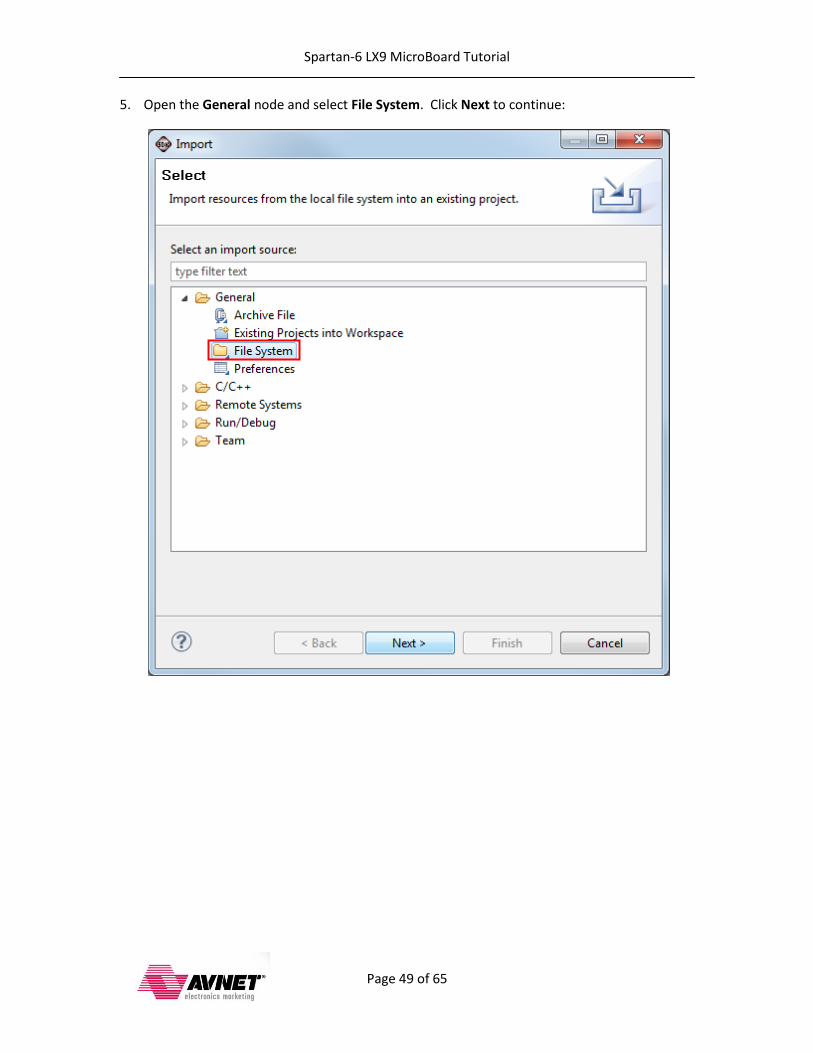
5. Open the General node and select File System. Click Next to continue:
Spartan-6 LX9 MicroBoard Tutorial
Page 50 of 65
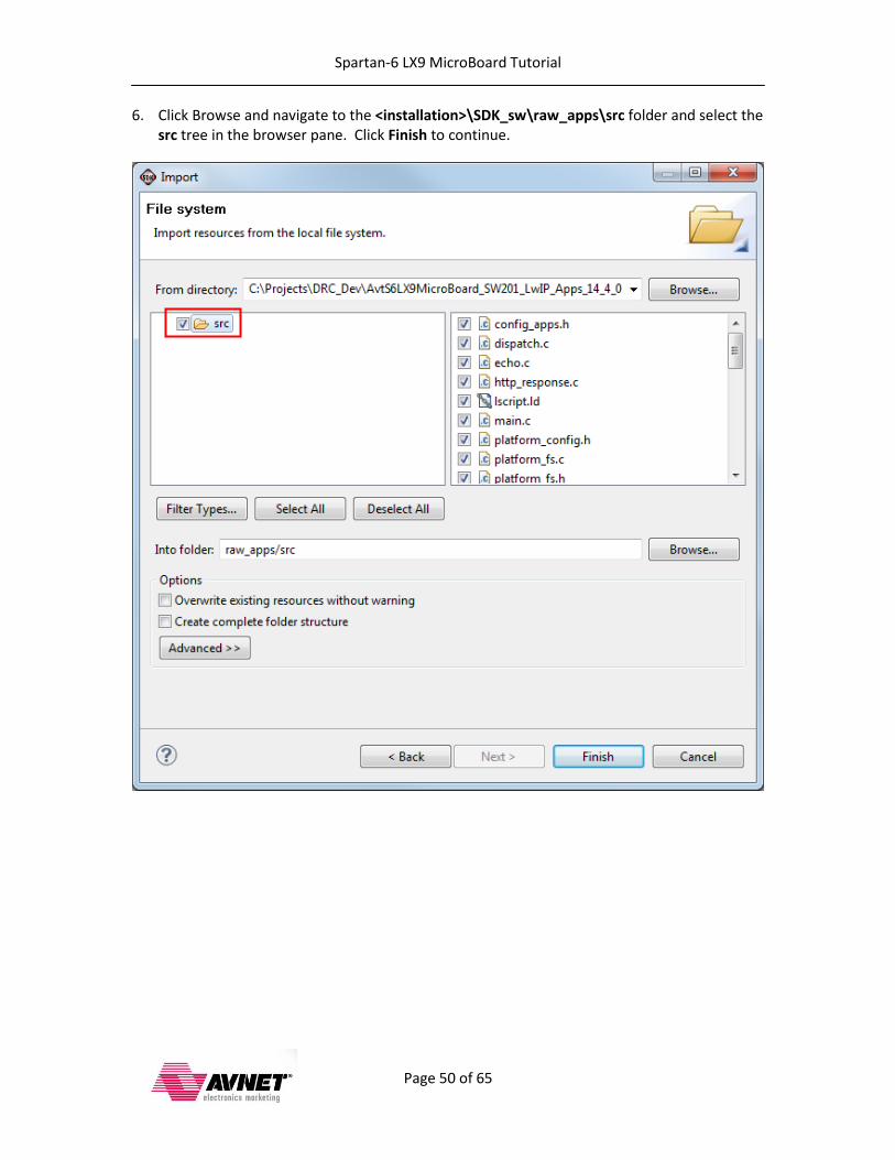
6. Click Browse and navigate to the <installation>\SDK_sw\raw_apps\src folder and select the src tree in the browser pane. Click Finish to continue.
Spartan-6 LX9 MicroBoard Tutorial
Page 51 of 65
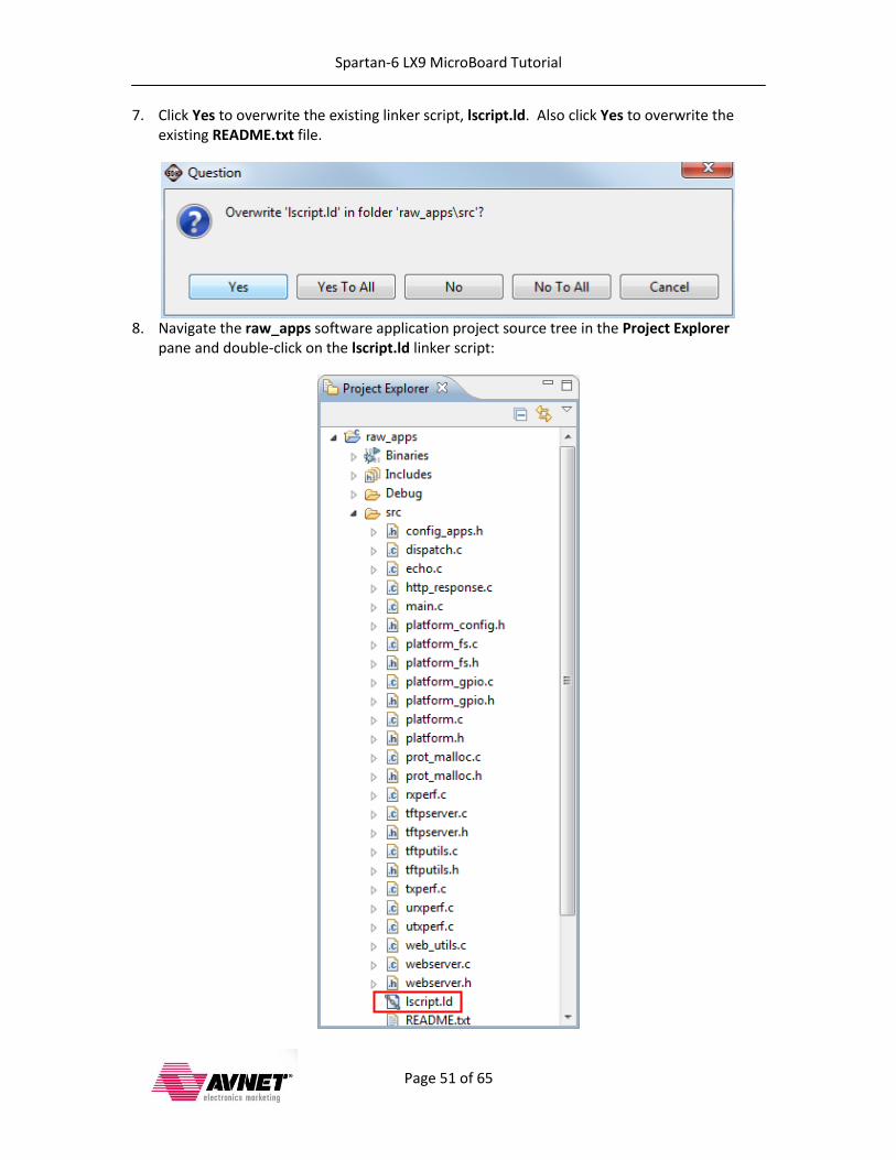
7. Click Yes to overwrite the existing linker script, lscript.ld. Also click Yes to overwrite the existing README.txt file.
8. Navigate the raw_apps software application project source tree in the Project Explorer
pane and double-click on the lscript.ld linker script:
Spartan-6 LX9 MicroBoard Tutorial
Page 52 of 65
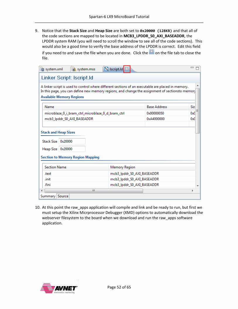
9. Notice that the Stack Size and Heap Size are both set to 0x20000 (128KB) and that all of the code sections are mapped to be located in MCB3_LPDDR_S0_AXI_BASEADDR, the LPDDR system RAM (you will need to scroll the window to see all of the code sections). This would also be a good time to verify the base address of the LPDDR is correct. Edit this field
if you need to and save the file when you are done. Click the on the file tab to close the file.
10. At this point the raw_apps application will compile and link and be ready to run, but first we must setup the Xilinx Micrprocessor Debugger (XMD) options to automatically download the webserver filesystem to the board when we download and run the raw_apps software application.
Spartan-6 LX9 MicroBoard Tutorial
Page 53 of 65
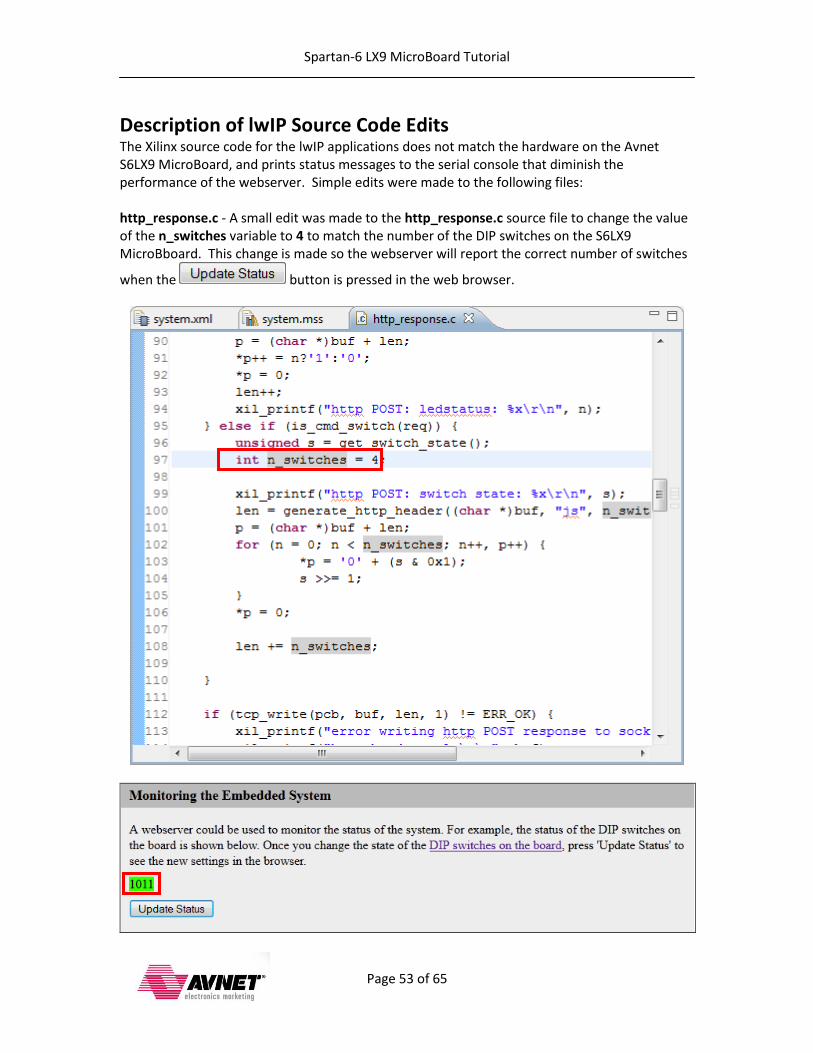
Description of lwIP Source Code Edits The Xilinx source code for the lwIP applications does not match the hardware on the Avnet S6LX9 MicroBoard, and prints status messages to the serial console that diminish the performance of the webserver. Simple edits were made to the following files: http_response.c - A small edit was made to the http_response.c source file to change the value of the n_switches variable to 4 to match the number of the DIP switches on the S6LX9 MicroBboard. This change is made so the webserver will report the correct number of switches
when the button is pressed in the web browser.
Spartan-6 LX9 MicroBoard Tutorial
Page 54 of 65
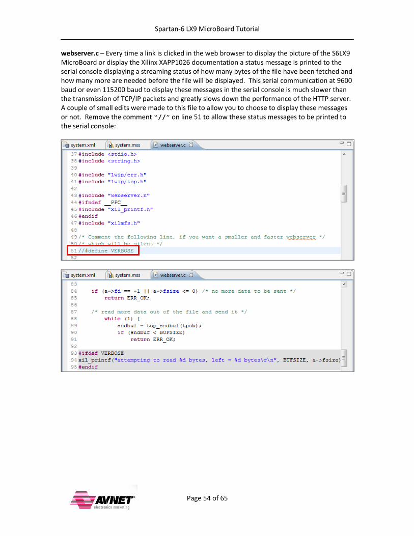
webserver.c – Every time a link is clicked in the web browser to display the picture of the S6LX9 MicroBoard or display the Xilinx XAPP1026 documentation a status message is printed to the serial console displaying a streaming status of how many bytes of the file have been fetched and how many more are needed before the file will be displayed. This serial communication at 9600 baud or even 115200 baud to display these messages in the serial console is much slower than the transmission of TCP/IP packets and greatly slows down the performance of the HTTP server. A couple of small edits were made to this file to allow you to choose to display these messages or not. Remove the comment “//” on line 51 to allow these status messages to be printed to the serial console:
Spartan-6 LX9 MicroBoard Tutorial
Page 55 of 65
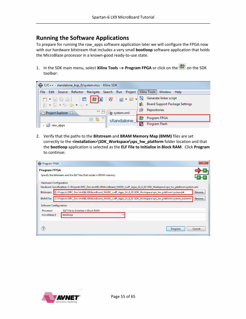
Running the Software Applications To prepare for running the raw_apps software application later we will configure the FPGA now with our hardware bitstream that includes a very small bootloop software application that holds the MicroBlaze processor in a known-good ready-to-use state.
1. In the SDK main menu, select Xilinx Tools Program FPGA or click on the on the SDK toolbar:
2. Verify that the paths to the Bitstream and BRAM Memory Map (BMM) files are set correctly to the <installation>\SDK_Workspace\xps_hw_platform folder location and that the bootloop application is selected as the ELF File to Initialize in Block RAM. Click Program to continue:
Spartan-6 LX9 MicroBoard Tutorial
Page 56 of 65
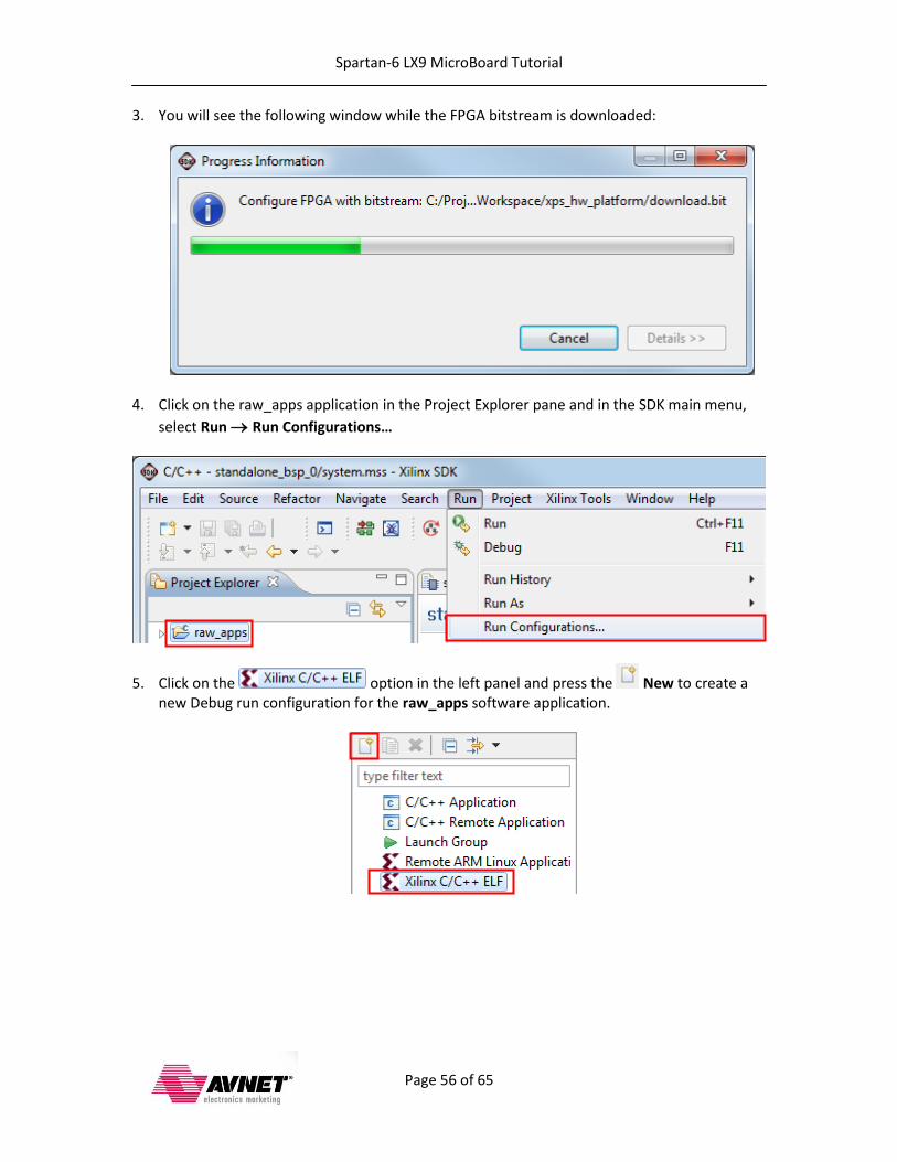
3. You will see the following window while the FPGA bitstream is downloaded:
4. Click on the raw_apps application in the Project Explorer pane and in the SDK main menu,
select Run Run Configurations…
5. Click on the option in the left panel and press the New to create a new Debug run configuration for the raw_apps software application.

Spartan-6 LX9 MicroBoard Tutorial
Page 57 of 65
6. Select the new raw_apps Debug run configuration. Click on the Device Initialization tab to specify the path to the webserver filesystem and the memory location where it is to be
stored on the LX9 MicroBoard. Click on the icon and navigate to the <installation>\demo folder then double-click the image.mfs file to add it to the run configuration. Note that this memory address (0xA5000000) must be the same as was specified earlier in the configuration of the BSP. This run configuration will download the filesystem along with the application executable. This saves us an extra step that we would otherwise have to do manually. Click the Run button to continue.
Spartan-6 LX9 MicroBoard Tutorial
Page 58 of 65
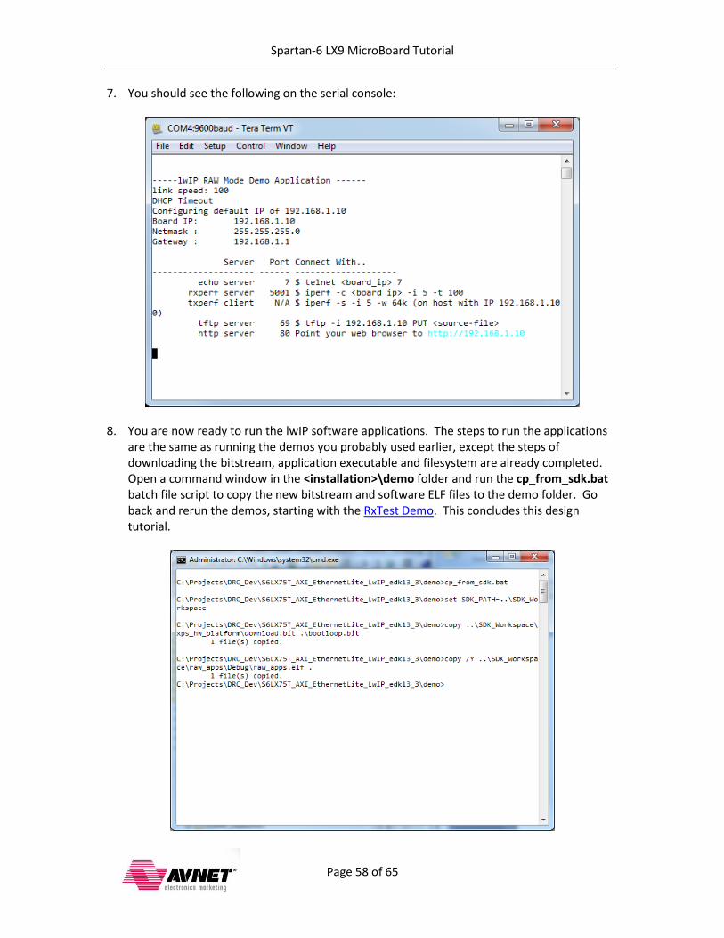
7. You should see the following on the serial console:
8. You are now ready to run the lwIP software applications. The steps to run the applications are the same as running the demos you probably used earlier, except the steps of downloading the bitstream, application executable and filesystem are already completed. Open a command window in the <installation>\demo folder and run the cp_from_sdk.bat batch file script to copy the new bitstream and software ELF files to the demo folder. Go back and rerun the demos, starting with the RxTest Demo. This concludes this design tutorial.
Spartan-6 LX9 MicroBoard Tutorial
Page 59 of 65
Modify the Webserver Filesystem After using the HTTP server demo you may want to experiment with creating your own filesystem for the webserver. Feel free to edit the <installation>\memfs\index.html to change the existing text and links or to add your own custom text and links to new files. If you are also familiar with JavaScript you can edit the provided JavaScript files to add new functionality or modify the existing methods to change the actions performed by the webserver. When you are done making your changes to the filesystem be sure to open a command window in the <installation>\memfs folder and at the command prompt enter
create_mfs.bat
to run the batch file to create a new Xilinx Memory Filesystem with your changes and copy the new filesystem image to the <installation>\demo folder. You can see the effects of your changes by running the demo_raw_apps.bat batch file as described in the Applications Demo section earlier in this document. If you want to preserve the original filesystem be sure to copy it to a new filename first.

Spartan-6 LX9 MicroBoard Tutorial
Page 60 of 65
Getting Help and Support Evaluation Kit home page with Documentation and Reference Designs http://em.avnet.com/s6microboard Avnet Spartan-6 LX9 MicroBoard forum: http://community.em.avnet.com/t5/Spartan-6-LX9-MicroBoard/bd-p/Spartan-6LX9MicroBoard
For Xilinx technical support, you may contact your local Avnet/Silica FAE or Xilinx Online Technical Support at www.support.xilinx.com. On this site you will also find the following resources for assistance:
Software, IP, and Documentation Updates
Access to Technical Support Web Tools
Searchable Answer Database with Over 4,000 Solutions
User Forums
Training - Select instructor-led classes and recorded e-learning options Contact Avnet Support for any questions regarding the Spartan-6 LX9 MicroBoard reference designs, kit hardware, or if you are interested in designing any of the kit devices into your next design.
http://www.em.avnet.com/techsupport You can also contact your local Avnet/Silica FAE.
Spartan-6 LX9 MicroBoard Tutorial
Page 61 of 65
Appendix: Installation of USB UART Driver Many of the Avnet evaluation boards are equipped with the Silicon Labs CP2102 USB-to-UART Bridge IC. This connects a PC’s USB port to the evaluation board and looks like a UART to the PC. A virtual COM port will be created on the PC by means of a Silicon Labs CP2102 USB-to-UART bridge driver. To install the Silicon Labs drivers follow the instructions listed below.
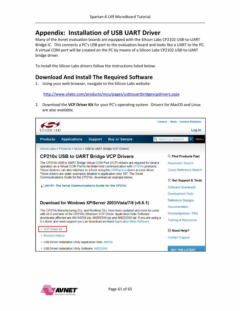
Download And Install The Required Software 1. Using your web browser, navigate to the Silicon Labs website:
http://www.silabs.com/products/mcu/pages/usbtouartbridgevcpdrivers.aspx
2. Download the VCP Driver Kit for your PC’s operating system. Drivers for MacOS and Linux
are also available.
Spartan-6 LX9 MicroBoard Tutorial
Page 62 of 65
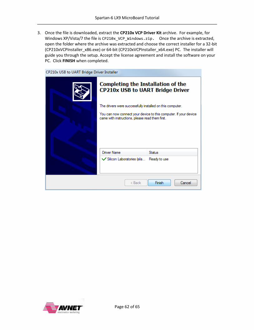
3. Once the file is downloaded, extract the CP210x VCP Driver Kit archive. For example, for Windows XP/Vista/7 the file is CP210x_VCP_Windows.zip. Once the archive is extracted, open the folder where the archive was extracted and choose the correct installer for a 32-bit (CP210xVCPInstaller_x86.exe) or 64-bit (CP210xVCPInstaller_x64.exe) PC. The installer will guide you through the setup. Accept the license agreement and install the software on your PC. Click FINISH when completed.
Spartan-6 LX9 MicroBoard Tutorial
Page 63 of 65
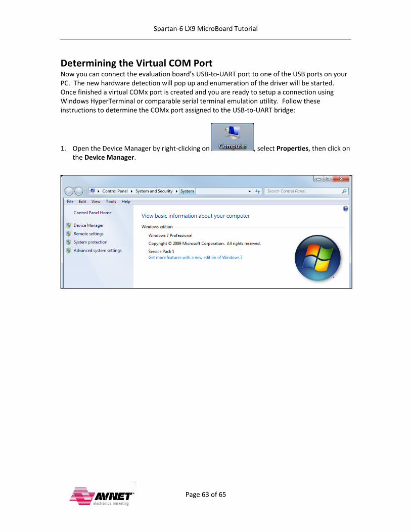
Determining the Virtual COM Port Now you can connect the evaluation board’s USB-to-UART port to one of the USB ports on your PC. The new hardware detection will pop up and enumeration of the driver will be started. Once finished a virtual COMx port is created and you are ready to setup a connection using Windows HyperTerminal or comparable serial terminal emulation utility. Follow these instructions to determine the COMx port assigned to the USB-to-UART bridge:
1. Open the Device Manager by right-clicking on , select Properties, then click on the Device Manager.
Spartan-6 LX9 MicroBoard Tutorial
Page 64 of 65
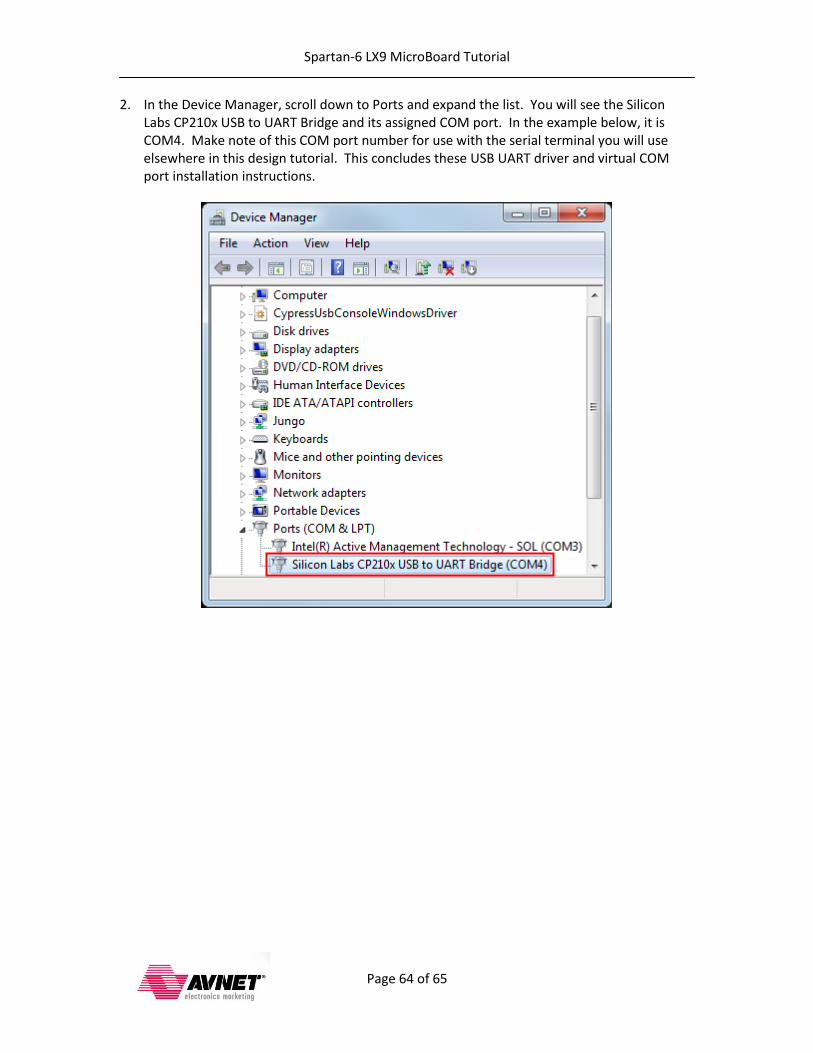
2. In the Device Manager, scroll down to Ports and expand the list. You will see the Silicon Labs CP210x USB to UART Bridge and its assigned COM port. In the example below, it is COM4. Make note of this COM port number for use with the serial terminal you will use elsewhere in this design tutorial. This concludes these USB UART driver and virtual COM port installation instructions.

Spartan-6 LX9 MicroBoard Tutorial
Page 65 of 65
Revision History Version Description Date
13.1.01 Initial release for EDK 13.1 7 Jul 2011
13.1.02 Various edits and fixes 8 July 2011
13.3.01 Initial release for EDK & SDK 13.3 11 Jan 2012
14.4.01 Release for EDK & SDK 14.4 20 Mar 2013