Embed Size (px)
Citation preview

P/N 84-9310011-02 Rev C
LVS® 9580/9585 Operating Instructions
English
LVS-9580 LVS-9585

LVS-9580 / LVS-9585 Operating Instructions – English
LVS-9580 / LVS-9585 Operating Instructions - English Page 2 of 28
Copyright ©2018 Omron Microscan Systems, Inc. Tel: +1.425.226.5700 / 800.762.1149 Fax: +1.425.226.8250
All rights reserved. The information contained herein is proprietary and is provided solely for the purpose of allowing customers to operate and/or service Omron Microscan-manufactured equipment and is not to be released, reproduced, or used for any other purpose without written permission of Omron Microscan.
Throughout this manual, trademarked names might be used. We state herein that we are using the names to the benefit of the trademark owner, with no intention of infringement.
GS1 Solution Partner
Disclaimer The information and specifications described in this manual are subject to change without notice.
Latest Manual Version For the latest version of this manual, see the Download Center on our web site at: www.microscan.com.
Technical Support For technical support, e-mail: [email protected] [email protected] [email protected] [email protected]
Warranty For current warranty information, see: www.microscan.com/warranty.
Omron Microscan Systems, Inc.
United States Corporate Headquarters +1.425.226.5700 / 800.762.1149
United States Northeast Technology Center +1.603.598.8400 / 800.468.9503
European Headquarters +31.172.423360
Asia Pacific Headquarters +65.6846.1214

LVS-9580 / LVS-9585 Operating Instructions – English
LVS-9580 / LVS-9585 Operating Instructions - English Page 3 of 28
Table of Contents
IMPORTANT INFORMATION ......................................................................................................... 4
SAFETY INSTRUCTIONS .............................................................................................................. 4
STATEMENT OF COMPLIANCE ................................................................................................... 4
ABOUT THE LVS-9580/9585 ......................................................................................................... 5
Quiet Zone ................................................................................................................................... 5
HARDWARE OVERVIEW ............................................................................................................... 6
LVS-95XX SOFTWARE STEPS ..................................................................................................... 6
Log In to LVS-95XX Software ..................................................................................................... 7
Turn On the LVS-9580/9585 Camera ......................................................................................... 9
Calibrate the LVS-9580/9585 .................................................................................................... 10
GRADING BARCODES ................................................................................................................ 13
CLEANING INSTRUCTIONS ........................................................................................................ 14
ENGINEERING SPECIFICATIONS .............................................................................................. 15
Supported Symbologies and Standards ................................................................................... 16
Supported Symbologies ......................................................................................................... 16 Supported Standards ............................................................................................................. 17
APPENDIX A – OPERATING THE LVS-9580 DPM VERIFIER ................................................... 18
APPENDIX B – OPERATING THE LVS-9585 VERIFIER ............................................................ 24

LVS-9580 / LVS-9585 Operating Instructions – English
LVS-9580 / LVS-9585 Operating Instructions - English Page 4 of 28
Important Information The LVS-9580/9585 arrives site packaged in a specially designed shipping carton. DO NOT discard this
shipping carton in case the system needs to be shipped or stored for any reason. Failure to use this carton when returning the product to Omron Microscan will void the warranty.
This guide is intended to help the user understand the features and functionality of the LVS-9580/9585. Be sure to reference the following additional resources: o Refer to the “LVS-95XX Series Software Installation Guide” for steps on installing LVS-95XX
Software. A hard copy version of the “LVS-95XX Series Software Installation Guide” is packaged with the system and an electronic version is located on the installation media.
o Refer to the “LVS-95XX Series Barcode Quality Station Operations Manual” for comprehensive steps on operating LVS-95XX Software. This manual is located on the installation media packaged with the system.
For questions or concerns about the performance of the LVS-9580/9585, please contact a local Omron Microscan Distributor or Omron Microscan Technical Support: [email protected] [email protected] [email protected] [email protected] Phone: 1.425.203.4841 Toll Free: 1.800.762.1149
Safety Instructions The LVS-9580/9585 has been carefully designed to provide years of safe, reliable performance. However, as with all electrical equipment, there are some basic precautions to avoid personal injury or damage to the system: Before using the system, carefully read all the installation and operating instructions. Observe all warning instruction labels on the system. Never insert anything into the openings of the system. Do not use the system near water or spill liquid into it. All components used to create the system are CE approved. All circuits were designed to incorporate
maximum safety. However, any equipment using electrical voltages may cause personal injury if improperly handled.
Do not attempt to work on the system with the USB cable connected. To avoid damaging the system, unplug the USB cable before cleaning. If the system ever needs repair, consult Omron Microscan or an Omron Microscan Distributor.
Statement of Compliance Manufacturer: Omron Microscan Systems, Inc., 700 SW 39th St., Renton, WA 98057, USA Производитель: «Омрон Майкроскан Системс Инк., США, Рентон, штат Вашингтон 98057, 700 SW 39th Street Representative: Omron Electronics Limited Liability Company, 125040, Russian, Moscow, Ulitsa Pravdy, 26. OGRN 10677746976582 Представитель: Общество с ограниченной ответственностью "Омрон Электроникс", 125040, Российская Федерация, город Москва, улица Правды, дом 26, ОГРН 10677746976582 Date of Manufacture: The first two digits of the serial number are the two-digit year of manufacture, or the year of manufacture +20 for serial numbers starting with 3. Дата изготовления: первые две цифры серийного номера являются двумя последними цифрами года изготовления + 20 для серийных номеров, начинающихся с 3.

LVS-9580 / LVS-9585 Operating Instructions – English
LVS-9580 / LVS-9585 Operating Instructions - English Page 5 of 28
About the LVS-9580/9585 The LVS-9580/9585 is a portable, handheld barcode verifier designed for off-line verification of barcodes to ISO/IEC standards. The LVS-9580/9585 is a 5.0 megapixel camera-based system that grades linear (1D) and two-dimensional (2D) codes up to 3 inches (76 mm) wide and up to 2 inches (51 mm) tall (including the quiet zone). See the “Quiet Zone” section below for more information on quiet zones.
The LVS-9580/9585 verifies barcode labels located on a variety of surfaces including corrugated cardboard boxes, shipping containers, and on a static (non-moving) web. The LVS-9580/9585 grades barcodes in either picket fence or ladder orientation.
Picket Fence Orientation
Ladder Orientation
The LVS-9580/9585 is 21 CFR Part 11 Compliant-Ready.
Quiet Zone The quiet zone is a clear space preceding the start character of a barcode symbol and follows the stop character. When reading/grading a barcode symbol, adequate space for the quiet zone must be allowed. The required quiet zone space for each barcode varies by symbology. An error message appears on the computer screen if not enough space has been allowed for the quiet zone.
1D Barcode Quiet Zone
2D Barcode Quiet Zone
Quiet Zone
Quiet Zone
Quiet Zone
Start Character
Stop Character

LVS-9580 / LVS-9585 Operating Instructions – English
LVS-9580 / LVS-9585 Operating Instructions - English Page 6 of 28
Hardware Overview The LVS-9580/9585 is comprised of the following hardware components:
Note: The image below shows the device approaching the symbol to be verified. The four rubber feet at the corners of the verifier window must be placed on the surface where the symbol is printed or marked.
The position of the device shown at left more closely approximates the orientation required in an application setting.
Important: The label shown above is 4” x 4”. The long linear symbol on the label would not fit in the field of view without using the Stitching Feature described in the LVS-95XX Series Operations Manual.
LVS-9580/9585 with USB cable and software installation flash drive.

LVS-9580 / LVS-9585 Operating Instructions – English
LVS-9580 / LVS-9585 Operating Instructions - English Page 7 of 28
LVS-95XX Software Steps Refer to the sections below for steps on:
Logging in to LVS-95XX Software
Turning on the LVS-9580/9585 camera
Calibrating the LVS-9580/9585
Note: Refer to the “LVS-95XX Series Software Installation Guide” for step-by-step instructions on installing LVS-95XX Software; a hard copy version of this guide is packaged with the system and an electronic version is located on the installation media.
Log In to LVS-95XX Software 1. Start LVS-95XX Software. The “Welcome” screen appears (see below).

LVS-9580 / LVS-9585 Operating Instructions – English
LVS-9580 / LVS-9585 Operating Instructions - English Page 8 of 28
2. Click the “Setup” tab. The “Login” box appears.
2. Enter admin (not case sensitive) in the Operator ID field and in the Password field.
3. Click “OK.” LVS-95XX Software will open.
4. Turn on the LVS-9580/9585 camera by following the steps in the next section entitled “Turn on the LVS-9580/9585 Camera.”

LVS-9580 / LVS-9585 Operating Instructions – English
LVS-9580 / LVS-9585 Operating Instructions - English Page 9 of 28
Turn On the LVS-9580/9585 Camera1. Click the “Setup” tab and select “9580/9585” in the “Camera” section (see below).
Note: When using only the LVS-9580/9585 (with no other LVS-95XX barcode verifier, such as the LVS-9510), “9580/9585” will be the only camera listed in the “Camera” section. When using the LVS-9580/9585 with the LVS-9510 (5 MP), both cameras appear in the “Camera” section. Select “9580/9585.”
2. Select “Auto-Sector” in the “Grading Mode” section (see screenshot above). This allows LVS-95XX Software to locate a barcode within the field of view and automatically draw a sector around the barcode.
3. Next, calibrate the LVS-9580/9585 (if using for the first time). See the next section for calibration steps.
Additional camera
LVS-9580 / LVS-9585
Select the “Auto-Sector” option

LVS-9580 / LVS-9585 Operating Instructions – English
LVS-9580 / LVS-9585 Operating Instructions - English Page 10 of 28
Calibrate the LVS-9580/9585
IMPORTANT:
The LVS-9580/9585 should be calibrated regularly. The entire calibration process takes less than 30 seconds to complete and ensures the LVS-9580/9585 is certified according to industry standards.
The Calibrated Conformance Standard Test Card should be replaced every two years.
It is recommended to clean the LVS-9580/9585 window prior to calibration. See the “Cleaning Instructions” section for more information.
1. To calibrate the LVS-9580/9585, click the “Calibration” tab.
2. Locate the Calibrated Conformance Standard Test Card (“test card”) that was packaged with the systemand place the test card on a flat surface.
Calibration Card ReferenceModel Calibration Card Type Replacement P/N Symbol Number on Card
LVS-9580 HD Data Matrix 98-CAL022 Data Matrix Symbol 1
LVS-9585 HD
LVS-9510 6.25" GS1-128 98-CAL021 GS1-128
All Other LVS-95XX Products EAN/UPC (Shown Below) 98-CAL020 UPC-A or EAN-13
Example of a UPC/EAN test card:
Master Grade Barcodes

LVS-9580 / LVS-9585 Operating Instructions – English
LVS-9580 / LVS-9585 Operating Instructions - English Page 11 of 28
3. Firmly grip the LVS-9580/9585 handle. There is no need to pull the trigger at this time (pulling the trigger causes the LVS-9580/9585 to capture a live image; however, the image is automatically live while the system is in Calibration mode).
4. Place the LVS-9580/9585 window over one of the Master Grade barcodes making sure the four rubber feet surrounding the window rest firmly on a flat, stable surface. The rubber feet hold the test card in place and prevent movement of the test card. See example of Master Grade barcodes above. It is important to note that not all of the rubber feet will fit onto the calibration card.
Not all of the rubber feet will fit onto the calibration card.
Verifier Window

LVS-9580 / LVS-9585 Operating Instructions – English
LVS-9580 / LVS-9585 Operating Instructions - English Page 12 of 28
5. On the “Calibration” tab, make sure the blue line travels through the middle of the PASS portion of thebarcode as shown below.
LVS-9580 / LVS-9585 (UPC/EAN Calibration Card, 98-CAL020)
LVS-9580 HD / LVS-9585 HD (Data Matrix Calibration Card, 98-CAL022)
6. Click the Calibrate button. Successful calibration is indicated by a green “Calibration OK” message. Failed calibration is
indicated by a red “Calibration Needed” message.
7. If calibration fails: Re-scan the Master Grade symbol and follow the above steps to calibrate. It may take two or three
attempts before calibration is complete. If calibration continues to fail, contact Omron Microscan or an Omron Microscan representative for
further instructions.
IMPORTANT: The calibration score will hardly ever match exactly; this is normal and acceptable as long as the scores are within +/- 3 percentage points.
8. When calibration is complete, click the “Grading” tab to grade barcodes. See the next section for stepson grading barcodes.
Enter the Decodability, Contrast, Modulation, and Rmax values from the UPC/EAN Calibration Card in the Goal column shown at left.
The blue line must pass through the “PASS” portion of the barcode.
Place Symbol # 1 of the Data Matrix Calibration Card within the field of view so that it is roughly equidistant from the borders of the blue sector box, as shown at left.
Be sure the Contrast and Rmax values under Goal match those printed on the Calibration Card. If they do not match, either you have the wrong card for the system or you must change the Goal values.

LVS-9580 / LVS-9585 Operating Instructions – English
LVS-9580 / LVS-9585 Operating Instructions - English Page 13 of 28
Grading Barcodes (Excluding DPM Grading) 1. Click the “Grading” tab.
2. Firmly grip the LVS-9580/9585 handle and press and hold the trigger (do not release the trigger).
3. Place the LVS-9580/9585 window over the barcode ensuring the four rubber feet surrounding the window rest on the substrate (media/label material). The rubber feet hold the substrate in place and minimize movement of the substrate.
4. The barcode image appears on the customer-supplied computer screen with a green plus symbol (+) located on the barcode image.
Note: If the green plus symbol (+) is not appearing on the barcode image, click the “Setup” tab and make sure “Auto-sector” is selected in the “Grading mode” section (see below).
5. Slowly move the LVS-9580/9585 as needed to place the green plus symbol over the center of the barcode image (make sure the rubber feet rest on the substrate). Then, release the trigger.
Tip: Positioning the green plus symbol over the center of the barcode image may take a few moments when first learning to use the LVS-9580/9585. Position the center of the LVS-9580/9585 window as close as possible to the center of the barcode image. Please note that when moving the system, the camera reads in a mirrored view. For example, when the camera is moved to the right, the image moves left. If the camera is moved up, the image moves down.
6. LVS-95XX Software analyzes the barcode and reports a grade score between 4.0 (A grade) and 0.0 (F grade) on the “Grading” tab.
Refer to the “Grading Tab” section in the “LVS-95XX Series Barcode Quality Station Operations Manual” for more information on grading barcodes; this manual is located on the installation media packaged with the system.

LVS-9580 / LVS-9585 Operating Instructions – English
LVS-9580 / LVS-9585 Operating Instructions - English Page 14 of 28
Cleaning Instructions The LVS-9580/9585 window may need to be cleaned daily, depending on use. Debris on the window may cause the LVS-9580/9585 to not grade accurately.
Locate the following supplies:
Commercially available household glass cleaner, such as Windex®, Glassex®, or Mr. Muscle®. Do not use an industrial-strength glass cleaner.
Soft, lint-free, non-abrasive towel or cloth
Dampen the cloth with the household glass cleaner and gently wipe the window. Inspect the window closely, looking for any label debris that may be stuck on the window. Do not scrape the window with a sharp object as this may damage the window. Any damage to the window will be detected during the calibration process.
IMPORTANT:
DO NOT directly spray the window with glass cleaner; always spray a towel or cloth with household glass cleaner and then gently wipe the window.
DO NOT use an industrial-strength glass cleaner.
Please contact an Omron Microscan Distributor or Omron Microscan Technical Support with questions or concerns about the performance of the LVS-9580/9585:
[email protected] [email protected] [email protected] [email protected] Phone: 1.425.203.4841 Toll Free: 1.800.762.1149

LVS-9580 / LVS-9585 Operating Instructions – English
LVS-9580 / LVS-9585 Operating Instructions - English Page 15 of 28
Engineering Specifications
Physical Properties
Height 8.5” 215.9 mm
Width 4.75” 120.6 mm
Depth 5.5” 139.7 mm
Weight Unpackaged Weight = 1 lb. 8 oz. (0.68 kg)
Shipping weight (includes all items packaged in shipping box, such as cables, manuals, etc.) = Approx. 3 pounds 5 oz. (1.51 kg)
Imaging Device
5 megapixel camera
Object Distance: Contact
Field of View
3.0” (76.19 mm) horizontally
2.25” (57.15 mm) vertically
1.75” x 1.75” (44 mm x 44 mm) for DPM (direct part mark) software selection
1.3" x 1.0" (33 mm x 25 mm) for LVS-958X HD models
Minimum Barcode X Dimension
1D = 4.0 mils (0.10 mm)
2D = 5.9 mils (0.15 mm)
LVS-958X HD can verify a DPM Data Matrix symbol down to 2.0 mil (0.05 mm) and a standard Data Matrix down to 5.0 mil (0.127 mm).
Minimum PC Requirements (PC Supplied by Customer)
Windows® 7 Pro SP1, Windows® 10 Pro
Intel® Core™ i3 Processor or equivalent
4 GB RAM
800 x 600 Resolution
One available USB 2.0 port
Power Requirements
USB-Powered 5VDC @ 400mA
Light Source
LVS-9580: Red 660 nm filter
LVS-9585: Red dome (660 nm); White dome, 30º angle
Communication
USB 2.0 A/MINI-B cable 2.0 m (6.5 ft.)
Operating Temperature
-5º C (23º F) to 45º C (113º F)
Storage Temperature
-20º C (-4º F) to 60º C (140º F)
Relative Humidity
Operating: 20% to 80% (non-condensing)
Storage: 20% to 95% (non-condensing)
Calibration
EAN/UPC Calibrated Conformance Test Card
Data Matrix Calibration Conformance Test Card (HD models only)
Safety Compliant
RoHS/WEEE compliant CE
q
Specifications and images subject to change.

LVS-9580 / LVS-9585 Operating Instructions – English
LVS-9580 / LVS-9585 Operating Instructions - English Page 16 of 28
Supported Symbologies and Standards Below are just a few of the Symbologies and Standards supported by the LVS-9580/9585. Contact Omron Microscan for a full list of supported Symbologies and Standards.
Supported Symbologies
1D (Linear) Codes:
Aztec Code
Codabar
Code 128
Code 39
Code 93
DataBar Expanded
DataBar Limited
DataBar Omnidirectional
DataBar Stacked
DataBar Truncated
DataBar
EAN/JAN-13
EAN/JAN-8
Enterprise Intelligent Barcode (EIB) 4-State (4SB)
French CIP
GS1-128
HIBC
Interleaved 2 of 5 (ITF)
ITF-14
Japan Post
MaxiCode
MSI Plessey
Pharmacode – Italian
Pharmacode – Laetus
PZN 7 and PZN 8
UPC-A
UPC-E
USPS-128
USPS Intelligent Mail Barcode (also referred to as 4-State Barcode)
2D (Two-Dimensional) Codes:
Below are 2D codes (including 2D Composite Components abbreviated as CC) available for use with the “1D and 2D Barcode Verification” option:
DataBar with CC-A, CC-B, or CC-C
EAN/JAN-13 with CC-A, CC-B, or CC-C
EAN/JAN-8 with CC-A, CC-B, or CC-C
ECC-200 (Data Matrix)
Enterprise Intelligent Barcode (EIB) Complex Mail Data Marks (CMDM)
GS1-128 with CC-A, CC-B, or CC-C
Micro QR Code
MicroPDF417
PDF417
QR Code
UPC-A with CC-A, CC-B, or CC-C
UPC-E with CC-A, CC-B, or CC-C

LVS-9580 / LVS-9585 Operating Instructions – English
LVS-9580 / LVS-9585 Operating Instructions - English Page 17 of 28
Supported Standards ISO Conformance Standards: ISO/IEC 15415
ISO/IEC 15416
ISO/IEC 15426-1
ISO/IEC 15426-2
ISO/IEC TR29158 (DPM models only) / AIM DPM-1-2006
GS1 US Certification: Data Matrix for Healthcare
Data Matrix (ECC 200)
EAN/UPC
EAN/UPC and Extended Codes
EAN/UPC with CC
GS1 DataBar Omnidirectional
ITF-14
GS1 Databar-14 with CC (formerly RSS-14 with CC)
UCC/EAN with Supplementals
UCC/EAN-128
UCC/EAN-128 with CC
Application Standards: AIAG/DAMA/JAPIA/Odette
ISO/IEC TR29158
DHL
FPMAJ
GS1 General Specifications
HDMA Guidelines
Health Industry Barcode (HIBC)
ISO/IEC 15415/15416
Japan Codabar
Laetus Miniature Pharmacode
Laetus Pharmacode
Laetus Standard
MIL-STD-130N Change 1

LVS-9580 / LVS-9585 Operating Instructions – English
LVS-9580 / LVS-9585 Operating Instructions - English Page 18 of 28
Appendix A – Operating the LVS-9580 DPM Verifier The LVS-9580 DPM Verifier is a Direct Part Mark (DPM) verifier. The LVS-9580 DPM Verifier can be used to verify the symbol quality and structure of a Data Matrix or QR Code symbol that is permanently affixed to a manufactured item. Correct application standards must be used to verify the structure of the data contained in the direct part mark. This list of available standards is located on the Setup Screen. The software is programmed to use the following application standards:
DPM ISO/IEC TR29158:2011(E)
DPM + MIL-STD-130N w/Change 1 (16NOV2012)
DPM + UII + MIL-STD-130N w/Change 1 (16NOV2012)
GS1 TABLE 7 DPM (non-medical)
GS1 TABLE 7 DPM (medical-ink)
GS1 TABLE 7 DPM (medical, Direct A, connected)
GS1 TABLE 7 DPM (medical, Direct B, not connected)
The LVS-9580 DPM Verifier can be used as a print quality verifier (15415/15416, GS1) and can verify according to DPM verification standards (ISO/IEC TR29158, MIL-STD-130, UII, and GS1) provided that those upgrades have been purchased.
The LVS-9580 DPM Verifier can also operate in conjunction with the LVS-9510 Verifier. Both the LVS-9580 DPM and LVS-9510 can be connected to the same computer, allowing you to switch between devices. Note: The LVS-9510 does not support DPM verification.
DPM Verification DPM verification does not follow the same rules as traditional 1D and 2D verification. Differences:
All dot peen symbols must now be read with the L-pattern placed squarely in the field of view.
Symbol Contrast is no longer measured. SC (Symbol Contrast) has been replaced with a new parameter called Cell Contrast (CC). A cell contrast value of 30% is now an A Grade.
Modulation and Reflectance Margin are no longer measured. These two parameters are replaced with a new parameter called Cell Modulation (CM).
The LVS-9580 DPM Verifier can grade a direct part mark on most surfaces. The usable field of view is now limited to 1.75” (44 mm) by 1.75” (44 mm).
The LVS-9580 HD has a usable field of 1.3” (33 mm) by 1.0” (25 mm).
Average Grade (AG) is no longer reported. A parameter called Distributed Damage Grade (DDG) has taken its place. DDG indicates the average of the notional damage grade at the D Grade level.
A parameter has been created called Minimum Reflectance. A Minimum Reflectance greater than or equal to 5% is considered to be an A Grade (4.0). If it is less than 5% then it is an F Grade (0.0).
The final grade now reports additional information:
DPM4.0/12/660/D o DPM = Indicates that the DPM rules have applied to the final grade.
o 4.0 = Indicates the final grade point average. This final grade will always be a whole number.
o 4.0 = A Grade, 3.0 = B Grade, 2.0 = C Grade, 1.0 = D Grade, 0.0 = F Grade.
o 12 = Aperture Size o
o 660 = Color of the light. 660 = red.
o D = Angle of the light source. A D angle indicates a dome light.

LVS-9580 / LVS-9585 Operating Instructions – English
LVS-9580 / LVS-9585 Operating Instructions - English Page 19 of 28
Grading The LVS-9580 Grading Screen shows 6 boxes on the right side of the viewing window. These will represent which lighting modes are being used to Grade the DPM code. The LVS-9580 will only use Red Dome.
There is also a button on this screen titled Lighting. This is not authorized for use with the LVS-9580.
Grading a DPM Symbol On the Grading Screen hold down the trigger switch. The target DPM indicator (an upside-down red letter ‘T’) then appears in the viewing window. A pop-up window appears at the top of the screen which says “Hold trigger while searching”. Position the target DPM indicator so that it is in contact with the DPM symbol being graded. (Note: Positioning the target DPM indicator near the bottom of the symbol as show below is preferred for reflective metal parts to avoid the camera reflection interfering with the grading results.) Be sure the symbol is square to the field of view. Then hold the LVS-9580 steady. (The software does not grade the code until there is no motion detected.) After the symbol is found, the blue box will outline the symbol.
Red upside-down T.

LVS-9580 / LVS-9585 Operating Instructions – English
LVS-9580 / LVS-9585 Operating Instructions - English Page 20 of 28
Once the software has found the DPM symbol, it will report what grade has been detected. There is a pop-up window at the top of the screen that reports the best grade found. It will not stop looking for a better grade until either an A Grade has been reached or the user releases the trigger.
If an A Grade is found, a pop-up window advises the user to “Release trigger”.
The software will continue to change exposure (brightness) in an attempt to decode the symbol. The software will not stop looking or attempting to find the best grade until the trigger is released. If a symbol is not found after 20 seconds then the DPM mark should be re-oriented within the field of view and another attempt to grade should be made.
Best DPM Grade being reported.

LVS-9580 / LVS-9585 Operating Instructions – English
LVS-9580 / LVS-9585 Operating Instructions - English Page 21 of 28
The Zoom Feature A user can select the “Zoom” button located within the View Box. Then, after the grading process is done, the DPM symbol will be magnified. This will help in viewing small codes.
Before Zoom Is Applied Zoomed-In Image
Remote Grading of a DPM Symbol A user can push CTRL + SHFT and the software will interpret this as a trigger switch command. This is useful when the optional stand is used.
Grading with a Shiny Surface Some direct part marks are created on a shiny metallic surface. When this occurs, the image of the camera can be seen in the center of the field of view. The operator needs to move the direct part mark away from the center of the screen so that the dark circle does not interfere with the grading process.
Drawing a Blue Sector This feature is not allowed when grading a DPM symbol.

LVS-9580 / LVS-9585 Operating Instructions – English
LVS-9580 / LVS-9585 Operating Instructions - English Page 22 of 28
Try Re-Grading When a direct part mark fails to read, position the symbol in a different part of the field of view. The software is sensitive to motion and may capture a slightly blurred image, which will cause the software not to grade it correctly. The optional accessory stand, part # 98-9000125-01, can be used to hold the LVS-9580 in a fixed position.
Keep the “L” pattern square to the field of view.
For most dot peen DPM symbols, the cells are formed by dots and are not connected to each other. This will prompt the software to enhance the image by “connecting the dots”. However, the operator must keep the L-pattern square to the field of view in order for the software to grade the symbol correctly.
Correct: DPM symbol is square to the FOV
Incorrect: DPM symbol is not square to the FOV
Structure This system is designed to check the Data Structure for compliance to industry standards for MIL-STD-130, UII, and GS1. The embedded data is listed along with a description of what it stands for and reports the value used to determine what the embedded data is. The Data Structure Analysis can be printed.

LVS-9580 / LVS-9585 Operating Instructions – English
LVS-9580 / LVS-9585 Operating Instructions - English Page 23 of 28
Reports All results measured by the software are available in a printed report. These reports are also archived for future examination. An image of the direct part mark is attached to the printed report.

LVS-9580 / LVS-9585 Operating Instructions – English
LVS-9580 / LVS-9585 Operating Instructions - English Page 24 of 28
Appendix B – Operating the LVS-9585 Verifier
Grading DPM Symbols with the LVS-9585 Verifier The LVS-9585 DPM Verifier is different from the LVS-9580 DPM Verifier due to the addition of 9 different lighting modes:
RED Dome
WHITE Dome
RED 30 degree N + S+ E + W
RED 30 degree N + S
RED 30 degree E + W
RED 30 degree N
RED 30 degree S
RED 30 degree E
RED 30 degree W
These lighting modes are only available when using DPM Application Standards. They are not used for traditional 1D and 2D verification.
Setup Screen After choosing any of the DPM Application Standards, Automatic and Manual are grayed out within the Grading mode section. Auto-sector is the only choice.

LVS-9580 / LVS-9585 Operating Instructions – English
LVS-9580 / LVS-9585 Operating Instructions - English Page 25 of 28
Calibration Screen Follow the calibration procedure described on page 10. The Calibration Screen shows 6 lighting mode boxes on the right side of the viewing screen. During calibration, the Red and White box activates when that light mode is being calibrated. The individual N, S, E, and W light boxes do not activate during the calibration process. Clicking on the Red or White box confirms proper calibration for that lighting mode.
Grading Screen The LVS-9585 Grading Screen shows 6 boxes on the right side of the viewing window. These will represent which lighting modes are being used to grade the DPM code.
LVS-9580 / LVS-9585 Operating Instructions – English
LVS-9580 / LVS-9585 Operating Instructions - English Page 26 of 28
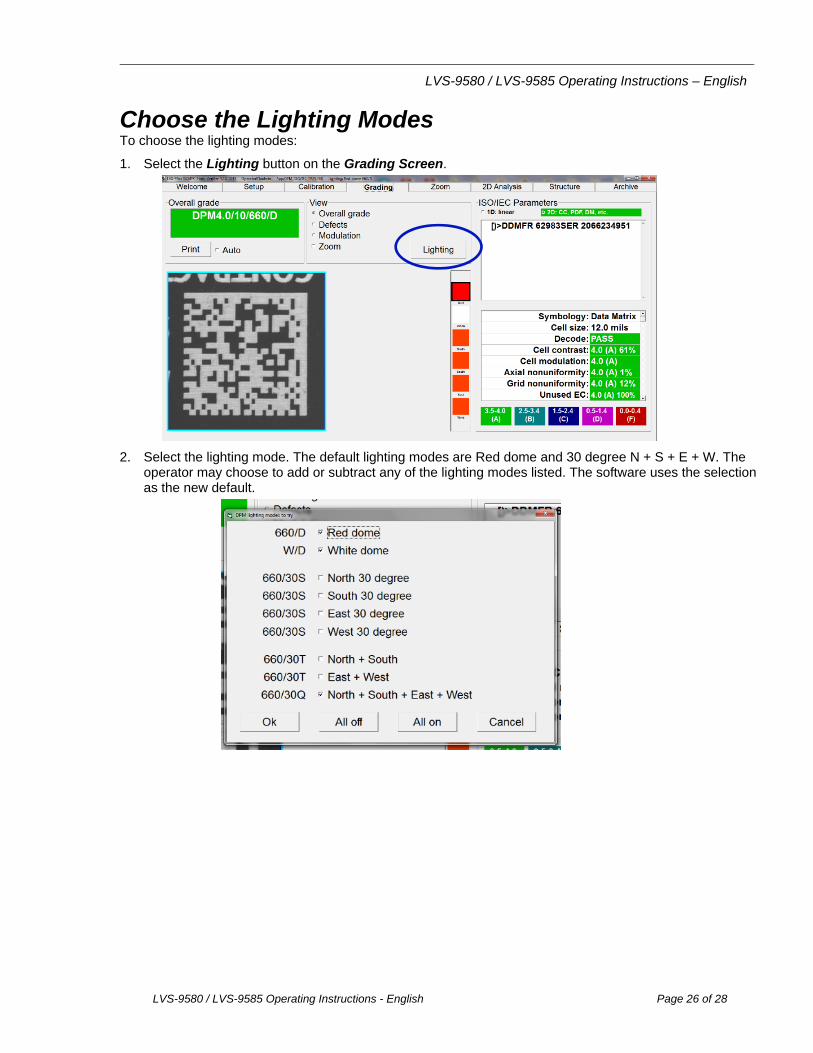
Choose the Lighting Modes To choose the lighting modes:
1. Select the Lighting button on the Grading Screen.
2. Select the lighting mode. The default lighting modes are Red dome and 30 degree N + S + E + W. The operator may choose to add or subtract any of the lighting modes listed. The software uses the selection as the new default.

LVS-9580 / LVS-9585 Operating Instructions – English
LVS-9580 / LVS-9585 Operating Instructions - English Page 27 of 28
Grading a DPM Symbol To grade a DPM symbol:
1. While viewing the Grading Screen, hold the verifyer trigger switch in. The target DPM symbol then appears in the viewing window. A pop-up window appears at the top of the screen which says “Hold trigger while searching.”
2. Position the DPM symbol so that it is square to the field of view and resting on the upside-down red ‘T’. Then hold the LVS-9585 steady. (The software does not grade the code until there is no motion detected.)
Once the software has found the DPM symbol, the screen will report what grade has been detected. There is a pop-up window at the top of the screen that reports the best grade found. It will not stop looking for a better grade until either an A Grade has been reached or you release the trigger.
Best DPM Grade being reported.

LVS-9580 / LVS-9585 Operating Instructions – English
LVS-9580 / LVS-9585 Operating Instructions - English Page 28 of 28
3. If an A Grade is found, a pop-up window advises you to “Release trigger”.
4. If the “Found” or “Adjusting” message is not shown after 20 seconds, reorient the mark within the field of
view and grade it again.
The Zoom Feature A user can select the “Zoom” button located within the View Box. Then, after the grading process is done, the DPM symbol will be magnified. This will help in viewing small codes.
Before Zoom Is Applied Zoomed-In Image
Remote Grading of a DPM Symbol To grade a DPM symbol remotely, push CTRL + SHFT. The software will interpret this as a trigger switch command. This is useful when the optional stand is used.