Embed Size (px)
Citation preview
Lubrication & Machining of Compacted Graphite Iron
R. Evans, F. Hoogendoorn, & E. Platt, Quaker Chemical Corporation,
Metalworking Division Laboratory
Scope:
Compacted graphite iron (CGI) continues to gain use within the automotive industry. The
material is being used for the manufacture of brake disks, exhaust manifolds, cylinder
heads, as well as diesel engine blocks.1 The higher strength properties of CGI, compared
to those of gray iron, enables the manufacture of engines with higher pressure operating
combustion chambers, yielding more efficient engines with reduced emissions levels. In
addition, the use of CGI enables the production of thinner walled parts, generating lighter
engines, and a subsequent further increase in fuel efficiency. Current limitations
associated with the use of CGI lie in its lower machinability properties relative to gray
iron, with higher tool wear rates experienced. For this reason, a deeper understanding of
the machining properties of CGI, along with an understanding of the metalworking fluid
properties required to reduce wear and extend tool life in CGI machining, would greatly
benefit industry and the continued expansion of CGI use. This paper will discuss the
results of studies done to investigate the machining properties of CGI, and the
metalworking fluid properties and composition which impact and potentially extend tool
life in CGI machining.
Results & Discussion
Properties of Gray Cast Iron & Compacted Graphite Iron
With much effort currently underway in industry to replace standard gray cast irons with
compacted graphite iron to produce lighter and higher strength parts, it is useful to
describe the differences both structurally and compositionally which give rise to the
differences in the material properties and machinability of these two metals. Gray cast
iron has traditionally been used for the production of engine blocks, cylinder heads, as
well as various other automotive components. The graphite in gray cast iron has a flake-
like structure. The predominance of interconnecting graphite flakes gives rise to a high
level of discontinuities and stress concentration effects in the matrix and subsequently
gives rise to the properties characteristic of gray irons. These being good thermal
conductivity, damping capacity, along with good machinability properties.2 Thus gray
cast iron is easily machined at low production costs, (higher metal removal rates with
long tool life). Different from gray cast iron, compacted graphite iron, has a graphite
structure much like that of coral. Such a graphite structure produces lower levels of
discontinuities and stress concentration effects within the metal, giving rise to higher
strength and toughness properties, as well as lower machinability.
In addition to graphite structure differences, there are significant compositional
differences between gray cast iron and CGI which also are largely responsible for the
differences in the machinability of these two metals. The presence of sulfur in gray cast
iron is considered to be a critical factor associated with the high machinability of this
metal.3,4
During machining of gray cast iron, the sulfur alloyed in the metal, combines
with manganese to form manganese sulfide (MnS) inclusions.5 During cutting, the MnS
inclusions are believed to assist in the chip breaking process as well to adhere to the
cutting tool surface forming a lubricating layer which reduces friction, protects against
oxidation and diffusion, and subsequently minimizes tool wear (especially at high cutting
speeds). In machining of compacted graphite iron, formation of such a layer does not
occur since the normal amount of sulfur added to CGI is around 0.01%, which is
approximately ten times lower than that added to gray iron. In addition, the residual
sulfur in compacted graphite iron tends to combine with magnesium, (element added to
enhance graphite nodulization), so there remains little sulfur free to combine with
manganese and form the MnS protective layer. Thus the lack of sulfur in compacted
graphite iron is believed to be a primary reason for the poorer machinability and higher
tool wear associated with the machining of this metal.
Due to these two factors (graphite morphology and sulfur concentration) the
machinability of CGI is considerably lower, and tool wear is considerably higher than
that experienced in gray cast iron machining. Previously reported studies, show that tool
life for milling and drilling operations of CGI can be one half, while tool life in CGI
boring operations have been seen to be just one-tenth of that obtained in comparable
machining operations with gray cast iron.6 Thus it is clear that obtaining a better
understanding of the lubrication and fluid requirements needed for improving the
machinability of CGI will greatly benefit its current and future use.
Machinability of Gray Cast Iron versus Compacted Graphite Iron
To study the differences in machinability between gray cast iron and CGI, machining
tests were conducted on a Bridgeport V2XT machine using a standard water based
metalworking fluid. The fluid used was an o/w macroemulsion which is known to
provide high levels of lubrication in ferrous machining operations. Testing involved the
drilling and subsequent reaming of Grade 450 compacted graphite iron as well as a Class
40 gray cast iron. Assessment of the machinability of the metals was made by
measurement of the cutting forces and tool wear occurring during the operation. Figure 1
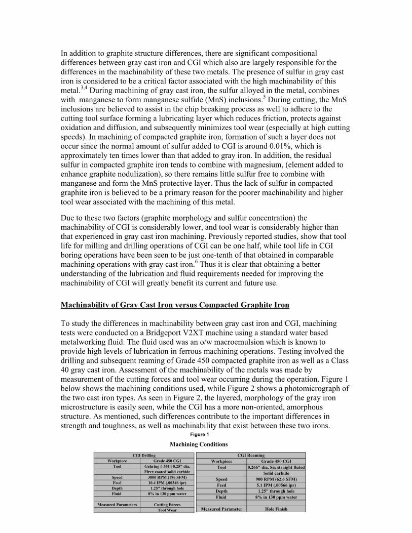
below shows the machining conditions used, while Figure 2 shows a photomicrograph of
the two cast iron types. As seen in Figure 2, the layered, morphology of the gray iron
microstructure is easily seen, while the CGI has a more non-oriented, amorphous
structure. As mentioned, such differences contribute to the important differences in
strength and toughness, as well as machinability that exist between these two irons.
Workpiece Grade 450 CGI
Tool Gehring # 5514 0.25" dia.
Firex coated solid carbide
Speed 3000 RPM (196 SFM)
Feed 10.4 IPM (.00346 ipr)
Depth 1.25" through hole
Fluid 8% in 130 ppm water
Measured Parameters Cutting Forces
Tool Wear
CGI Drilling
Workpiece Grade 450 CGI
Tool 0.266" dia. Six straight fluted
Solid carbide
Speed 900 RPM (62.6 SFM)
Feed 5.1 IPM (.00566 ipr)
Depth 1.25" through hole
Fluid 8% in 130 ppm water
Measured Parameter Hole Finish
CGI Reaming
Machining Conditions
Figure 1
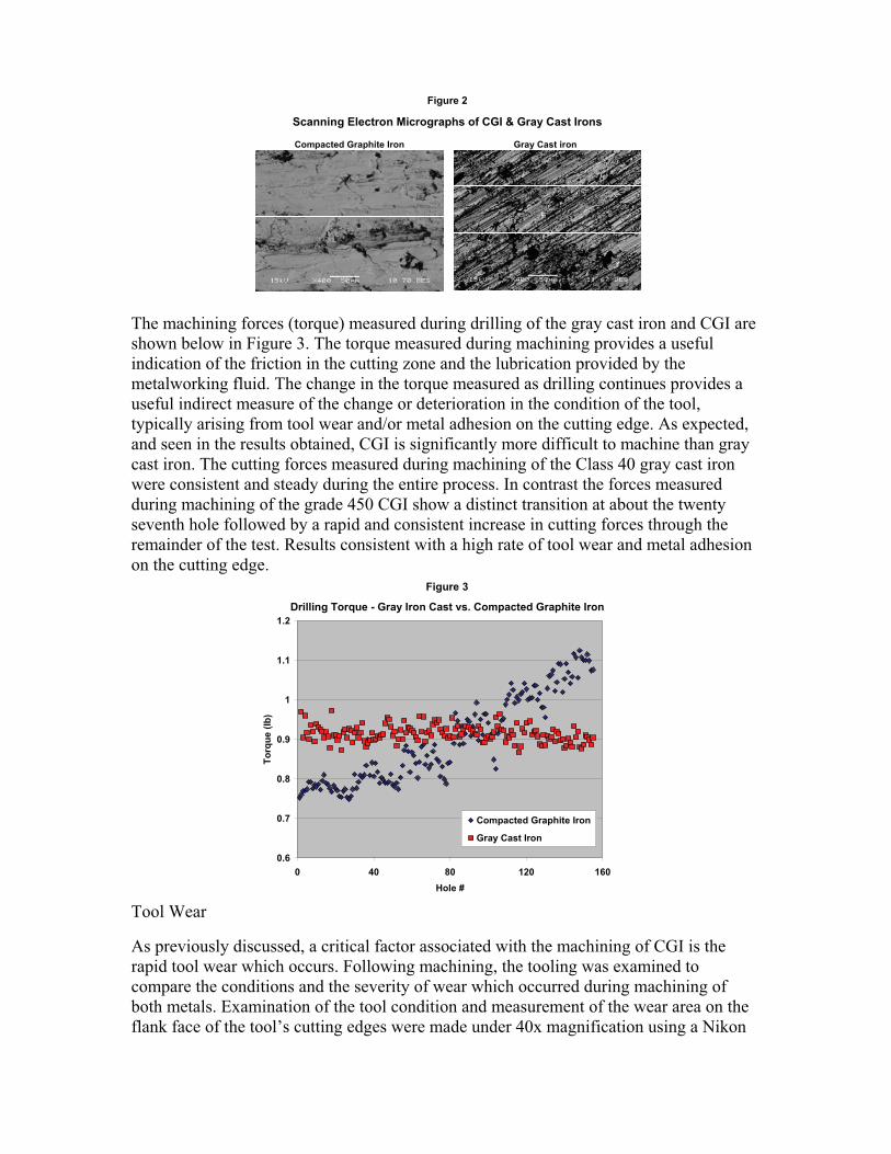
The machining forces (torque) measured during drilling of the gray cast iron and CGI are
shown below in Figure 3. The torque measured during machining provides a useful
indication of the friction in the cutting zone and the lubrication provided by the
metalworking fluid. The change in the torque measured as drilling continues provides a
useful indirect measure of the change or deterioration in the condition of the tool,
typically arising from tool wear and/or metal adhesion on the cutting edge. As expected,
and seen in the results obtained, CGI is significantly more difficult to machine than gray
cast iron. The cutting forces measured during machining of the Class 40 gray cast iron
were consistent and steady during the entire process. In contrast the forces measured
during machining of the grade 450 CGI show a distinct transition at about the twenty
seventh hole followed by a rapid and consistent increase in cutting forces through the
remainder of the test. Results consistent with a high rate of tool wear and metal adhesion
on the cutting edge.
Tool Wear
As previously discussed, a critical factor associated with the machining of CGI is the
rapid tool wear which occurs. Following machining, the tooling was examined to
compare the conditions and the severity of wear which occurred during machining of
both metals. Examination of the tool condition and measurement of the wear area on the
flank face of the tool’s cutting edges were made under 40x magnification using a Nikon
Compacted Graphite Iron Gray Cast iron
Scanning Electron Micrographs of CGI & Gray Cast Irons
Figure 2
Drilling Torque - Gray Iron Cast vs. Compacted Graphite Iron
0.6
0.7
0.8
0.9
1
1.1
1.2
0 40 80 120 160
Hole #
To
rqu
e (
lb)
Compacted Graphite Iron
Gray Cast Iron
Figure 3
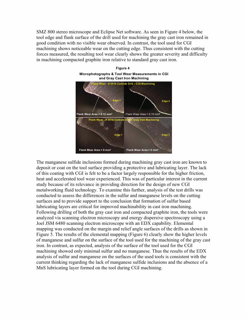
SMZ 800 stereo microscope and Eclipse Net software. As seen in Figure 4 below, the
tool edge and flank surface of the drill used for machining the gray cast iron remained in
good condition with no visible wear observed. In contrast, the tool used for CGI
machining shows noticeable wear on the cutting edge. Thus consistent with the cutting
forces measured, the resulting tool wear clearly shows the greater severity and difficulty
in machining compacted graphite iron relative to standard gray cast iron.
The manganese sulfide inclusions formed during machining gray cast iron are known to
deposit or coat on the tool surface providing a protective and lubricating layer. The lack
of this coating with CGI is felt to be a factor largely responsible for the higher friction,
heat and accelerated tool wear experienced. This was of particular interest in the current
study because of its relevance in providing direction for the design of new CGI
metalworking fluid technology. To examine this further, analysis of the test drills was
conducted to assess the differences in the sulfur and manganese levels on the cutting
surfaces and to provide support to the conclusion that formation of sulfur based
lubricating layers are critical for improved machinability in cast iron machining.
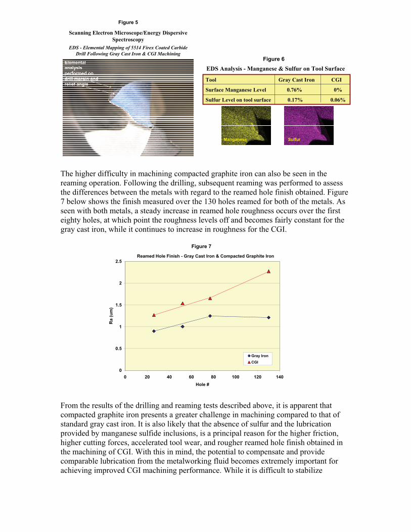
Following drilling of both the gray cast iron and compacted graphite iron, the tools were
analyzed via scanning electron microscopy and energy dispersive spectroscopy using a
Joel JSM 6480 scanning electron microscope with an EDX capability. Elemental
mapping was conducted on the margin and relief angle surfaces of the drills as shown in
Figure 5. The results of the elemental mapping (Figure 6) clearly show the higher levels
of manganese and sulfur on the surface of the tool used for the machining of the gray cast
iron. In contrast, as expected, analysis of the surface of the tool used for the CGI
machining showed only minimal sulfur and no manganese. Thus the results of the EDX
analysis of sulfur and manganese on the surfaces of the used tools is consistent with the
current thinking regarding the lack of manganese sulfide inclusions and the absence of a
MnS lubricating layer formed on the tool during CGI machining.
Flank Wear Area = 0.12 mm2 Flank Wear Area = 0.10 mm2
Flank Wear - # 5514 Carbide Drill – CGI Machining
Edge 2Edge 1
Flank Wear - # 5514 Carbide Drill – Gray Iron Machining
Flank Wear Area = 0 mm2Flank Wear Area = 0 mm2
Edge 1 Edge 2
Microphotographs & Tool Wear Measurements in CGI
and Gray Cast Iron Machining
Figure 4
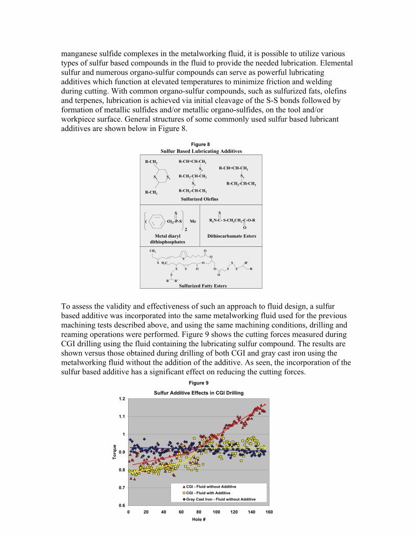
The higher difficulty in machining compacted graphite iron can also be seen in the
reaming operation. Following the drilling, subsequent reaming was performed to assess
the differences between the metals with regard to the reamed hole finish obtained. Figure
7 below shows the finish measured over the 130 holes reamed for both of the metals. As
seen with both metals, a steady increase in reamed hole roughness occurs over the first
eighty holes, at which point the roughness levels off and becomes fairly constant for the
gray cast iron, while it continues to increase in roughness for the CGI.
From the results of the drilling and reaming tests described above, it is apparent that
compacted graphite iron presents a greater challenge in machining compared to that of
standard gray cast iron. It is also likely that the absence of sulfur and the lubrication
provided by manganese sulfide inclusions, is a principal reason for the higher friction,
higher cutting forces, accelerated tool wear, and rougher reamed hole finish obtained in
the machining of CGI. With this in mind, the potential to compensate and provide
comparable lubrication from the metalworking fluid becomes extremely important for
achieving improved CGI machining performance. While it is difficult to stabilize
Elemental
analysis
performed on
drill margin and
relief angle
EDS - Elemental Mapping of 5514 Firex Coated Carbide
Drill Following Gray Cast Iron & CGI Machining
Scanning Electron Microscope/Energy Dispersive
Spectroscopy
Figure 5
Manganese Sulfur
Tool Gray Cast Iron CGI
Surface Manganese Level 0.76% 0%
Sulfur Level on tool surface 0.17% 0.06%
EDS Analysis - Manganese & Sulfur on Tool Surface
Figure 6
Reamed Hole Finish - Gray Cast Iron & Compacted Graphite Iron
0
0.5
1
1.5
2
2.5
0 20 40 60 80 100 120 140
Hole #
Ra
(u
m)
Gray Iron
CGI
Figure 7
manganese sulfide complexes in the metalworking fluid, it is possible to utilize various
types of sulfur based compounds in the fluid to provide the needed lubrication. Elemental
sulfur and numerous organo-sulfur compounds can serve as powerful lubricating
additives which function at elevated temperatures to minimize friction and welding
during cutting. With common organo-sulfur compounds, such as sulfurized fats, olefins
and terpenes, lubrication is achieved via initial cleavage of the S-S bonds followed by
formation of metallic sulfides and/or metallic organo-sulfides, on the tool and/or
workpiece surface. General structures of some commonly used sulfur based lubricant
additives are shown below in Figure 8.
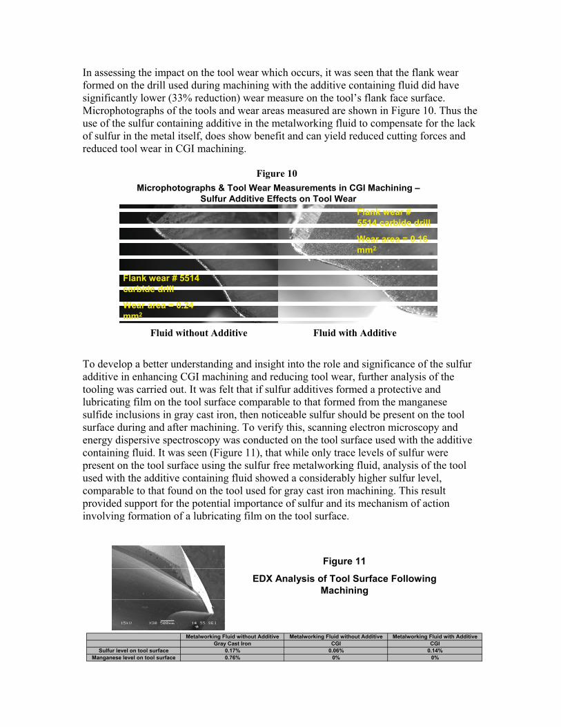
To assess the validity and effectiveness of such an approach to fluid design, a sulfur
based additive was incorporated into the same metalworking fluid used for the previous
machining tests described above, and using the same machining conditions, drilling and
reaming operations were performed. Figure 9 shows the cutting forces measured during
CGI drilling using the fluid containing the lubricating sulfur compound. The results are
shown versus those obtained during drilling of both CGI and gray cast iron using the
metalworking fluid without the addition of the additive. As seen, the incorporation of the
sulfur based additive has a significant effect on reducing the cutting forces.
R-CH=CH-CH2
Sx
R-CH2-CH-CH3
R-CH=CH-CH2
Sx
R-CH2-CH-CH2
Sy
R-CH2-CH-CH3
R-CH2
Sx Sy
R-CH2
S
( O)2-P-S Me
2
S
R2N-C- S-CH2CH2-C-O-R
O
CH3 O
O
S H3C O S R’
S S O O S S R
S O
R R’
S
Sulfurized Olefins
Metal diaryl
dithiophosphates
Dithiocarbamate Esters
Sulfurized Fatty Esters
Sulfur Based Lubricating Additives
Figure 8
Sulfur Additive Effects in CGI Drilling
0.6
0.7
0.8
0.9
1
1.1
1.2
0 20 40 60 80 100 120 140 160
Hole #
To
rqu
e
CGI - Fluid without Additive
CGI - Fluid with Additive
Gray Cast Iron - Fluid without Additive
Figure 9
In assessing the impact on the tool wear which occurs, it was seen that the flank wear
formed on the drill used during machining with the additive containing fluid did have
significantly lower (33% reduction) wear measure on the tool’s flank face surface.
Microphotographs of the tools and wear areas measured are shown in Figure 10. Thus the
use of the sulfur containing additive in the metalworking fluid to compensate for the lack
of sulfur in the metal itself, does show benefit and can yield reduced cutting forces and
reduced tool wear in CGI machining.
To develop a better understanding and insight into the role and significance of the sulfur
additive in enhancing CGI machining and reducing tool wear, further analysis of the
tooling was carried out. It was felt that if sulfur additives formed a protective and
lubricating film on the tool surface comparable to that formed from the manganese
sulfide inclusions in gray cast iron, then noticeable sulfur should be present on the tool
surface during and after machining. To verify this, scanning electron microscopy and
energy dispersive spectroscopy was conducted on the tool surface used with the additive
containing fluid. It was seen (Figure 11), that while only trace levels of sulfur were
present on the tool surface using the sulfur free metalworking fluid, analysis of the tool
used with the additive containing fluid showed a considerably higher sulfur level,
comparable to that found on the tool used for gray cast iron machining. This result
provided support for the potential importance of sulfur and its mechanism of action
involving formation of a lubricating film on the tool surface.
Figure 10
Fluid without Additive
Microphotographs & Tool Wear Measurements in CGI Machining –
Sulfur Additive Effects on Tool Wear
Flank wear # 5514
carbide drill
Wear area = 0.24
mm2
Flank wear #
5514 carbide drill
Wear area = 0.16
mm2
Fluid with Additive
Metalworking Fluid without Additive Metalworking Fluid without Additive Metalworking Fluid with Additive
Gray Cast Iron CGI CGI
Sulfur level on tool surface 0.17% 0.06% 0.14%
Manganese level on tool surface 0.76% 0% 0%
Figure 11
EDX Analysis of Tool Surface Following
Machining
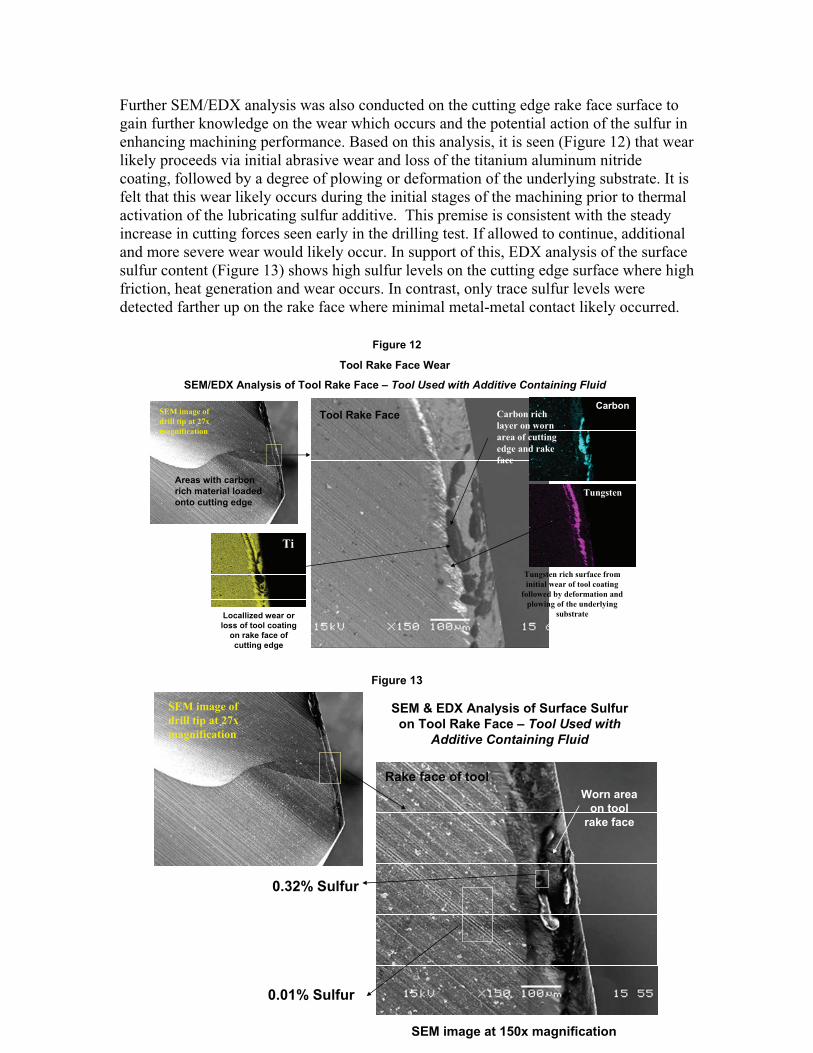
Further SEM/EDX analysis was also conducted on the cutting edge rake face surface to
gain further knowledge on the wear which occurs and the potential action of the sulfur in
enhancing machining performance. Based on this analysis, it is seen (Figure 12) that wear
likely proceeds via initial abrasive wear and loss of the titanium aluminum nitride
coating, followed by a degree of plowing or deformation of the underlying substrate. It is
felt that this wear likely occurs during the initial stages of the machining prior to thermal
activation of the lubricating sulfur additive. This premise is consistent with the steady
increase in cutting forces seen early in the drilling test. If allowed to continue, additional
and more severe wear would likely occur. In support of this, EDX analysis of the surface
sulfur content (Figure 13) shows high sulfur levels on the cutting edge surface where high
friction, heat generation and wear occurs. In contrast, only trace sulfur levels were
detected farther up on the rake face where minimal metal-metal contact likely occurred.
SEM image of
drill tip at 27x
magnification
Areas with carbon
rich material loaded
onto cutting edge
Tool Rake Face Carbon rich
layer on worn
area of cutting
edge and rake
face
Carbon
Tungsten rich surface from
initial wear of tool coating
followed by deformation and
plowing of the underlying
substrate
Tungsten
Ti
Locallized wear or
loss of tool coating
on rake face of
cutting edge
Tool Rake Face Wear
SEM/EDX Analysis of Tool Rake Face – Tool Used with Additive Containing Fluid
Figure 12
SEM image of
drill tip at 27x
magnification
SEM image at 150x magnification
0.01% Sulfur
0.32% Sulfur
Rake face of tool
SEM & EDX Analysis of Surface Sulfur
on Tool Rake Face – Tool Used with
Additive Containing Fluid
Worn area
on tool
rake face
Figure 13
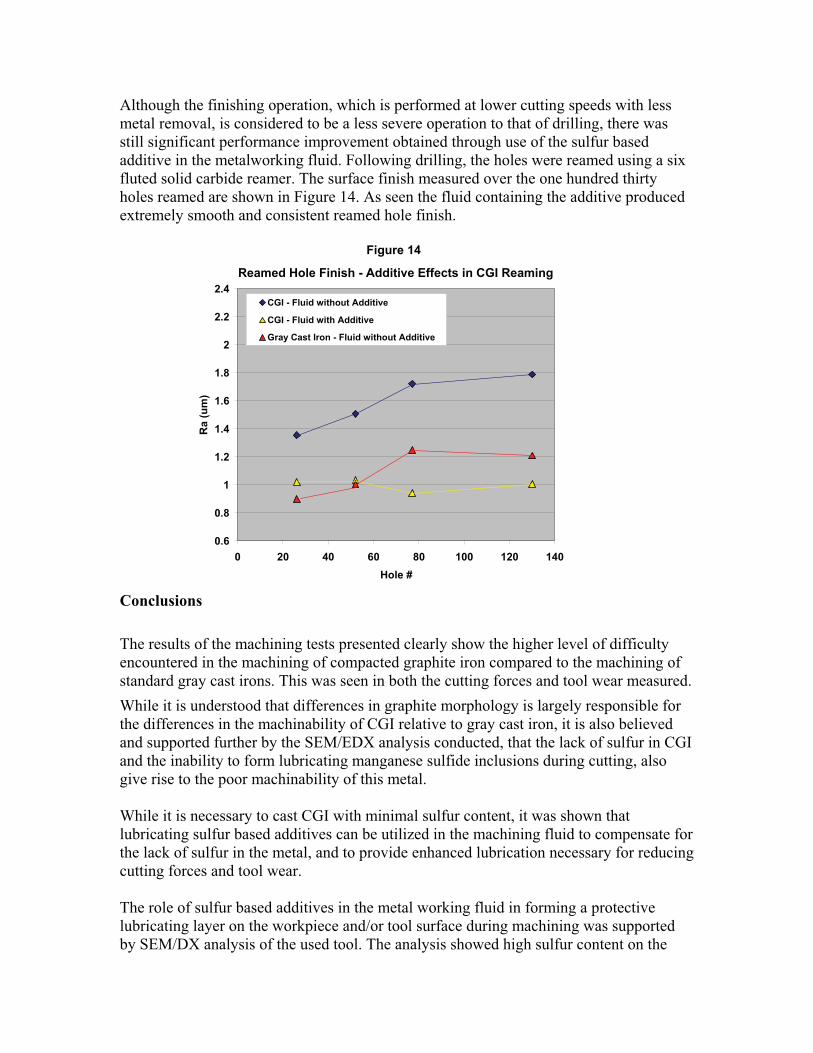
Although the finishing operation, which is performed at lower cutting speeds with less
metal removal, is considered to be a less severe operation to that of drilling, there was
still significant performance improvement obtained through use of the sulfur based
additive in the metalworking fluid. Following drilling, the holes were reamed using a six
fluted solid carbide reamer. The surface finish measured over the one hundred thirty
holes reamed are shown in Figure 14. As seen the fluid containing the additive produced
extremely smooth and consistent reamed hole finish.
Conclusions
The results of the machining tests presented clearly show the higher level of difficulty
encountered in the machining of compacted graphite iron compared to the machining of
standard gray cast irons. This was seen in both the cutting forces and tool wear measured.
While it is understood that differences in graphite morphology is largely responsible for
the differences in the machinability of CGI relative to gray cast iron, it is also believed
and supported further by the SEM/EDX analysis conducted, that the lack of sulfur in CGI
and the inability to form lubricating manganese sulfide inclusions during cutting, also
give rise to the poor machinability of this metal.
While it is necessary to cast CGI with minimal sulfur content, it was shown that
lubricating sulfur based additives can be utilized in the machining fluid to compensate for
the lack of sulfur in the metal, and to provide enhanced lubrication necessary for reducing
cutting forces and tool wear.
The role of sulfur based additives in the metal working fluid in forming a protective
lubricating layer on the workpiece and/or tool surface during machining was supported
by SEM/DX analysis of the used tool. The analysis showed high sulfur content on the
Reamed Hole Finish - Additive Effects in CGI Reaming
0.6
0.8
1
1.2
1.4
1.6
1.8
2
2.2
2.4
0 20 40 60 80 100 120 140
Hole #
Ra
(u
m)
CGI - Fluid without Additive
CGI - Fluid with Additive
Gray Cast Iron - Fluid without Additive
Figure 14
tool surface following machining. This level of sulfur was found to be comparable in
concentration to that found on the tool used for gray cast iron machining. It is also
believed that the formation of a sulfur based tribological film requires a level of heat.
This is supported by results of EDX analysis showing high sulfur levels on the cutting
edge surface where high friction, heat generation and wear was occurring, in contrast to
only trace sulfur levels at locations farther up on the tool rake face where minimal metal-
metal contact occurs.
References
1. Guesser, W., Schroeder,T., and Dawson, S. Production Experience With Compacted
Graphite Iron Automotive Components. AFS Transactions, DesPlaines, 20001
2. Jaszczak, J.A., Michigan Technological University, Dept of Physics. Available at
http://www.phy.mtu.edu/faculty/info/jaszczak/graphite.html, Dec 2001.
3. Mocellin, F., Melleras, E., & Guesser, W., Study of the Machinability of Compacted
Graphite Iron for Drilling Process, J. of the Braz. Soc. Of Mech. Sci. & Eng., Jan-Mar.
2004, Vol. 26, No 1 pp 22.
4. Korn, D., Challenges in Cutting CGI: Modern Machine Shop, Jan 2008
5. Boehs, L., Dissertation (Mechanical Engineering Masters degree) 1979, 105f.,
Department of Mechanical engineering, Universidade Federal de Santa Catarina,
Florianopolis.
6. Abele, E., Sahm, A., Schulz, H., Wear Mechanism When Machining Compacted
Graphite Iron, Annals of the CIRP, Vol 5, 51/1, 2002


![HIGHACTIVEINOCULANTFERROALLOYTO CONTROL … · 50 % CG) on the other (NG -nodular graphite; CG -compacted graphite) [1, 2]. Every one of these four types of cast iron has particular](https://img.dokumen.tips/doc/110x75/5b5a9aa47f8b9ab8578c3976/highactiveinoculantferroalloyto-control-50-cg-on-the-other-ng-nodular-graphite.jpg)