Embed Size (px)
Citation preview

Arc flash hazardsLow Voltage Circuit Breakers


Low Voltage Products & Systems 1ABB Inc. • 888-385-1221 • www.abb.com/lowvoltage 1SXU210204G0201
IndexLow voltage selectivity with ABB circuit breakers
Introduction ....................................................................................................... 2
Definitions, acronyms and terms used ............................................................... 3
Electrical arcs and their dangerous effects on people ......................................... 4
Reference standards ......................................................................................... 5
Arc flash hazard analysis .................................................................................... 6
Minimize arc flash effects ................................................................................... 8
ABB solutions .................................................................................................... 9
Annex A: Arc flash hazard (mathematical approach) ......................................... 12

2 Low Voltage Products & Systems
1SXU210204G0201 ABB Inc. • 888-385-1221 • www.abb.com/lowvoltage
Introduction
ScopeThere are essential requirements for electrical safety. Both domestic and international standards refer to steps and procedures to be taken for protection against hazards from electrical equipment. In particular, high temperatures and electrical arcs or arc flash can cause catastrophic dam-age. This document illustrates the approach taken in the United States to safeguard against the hazards derived from electrical arcs and their effects on human beings. It also sums up the recommendations of the US standards for all personnel working on live electrical equipment.
Basic Concepts:What is an Arc Flash? According to NFPA 70E (the relevant standard from the National Fire Protection Association), Arc Flash is a “dangerous condition associated with the release of energy caused by an electrical arc.” It is measured in terms of arc flash incident energy E (AFIE), which is used to determine the level of Personal Protective Equipment (PPE), and in terms of an arc flash protection boundary (FPB).
Arc Flash Hazard is the term used to define the danger to people working on live parts.
The Arc Flash Hazard Analysis defines the procedures which limit the damage of electrical arcs on personnel and, by measuring the released energy, defines the risk areas and determines the relevant level of the personal protective equipment (PPE).
An electrical arc occurs whenever there is a loss of insula-tion between two conductive objects at sufficient potential (voltage). Near high power electrical equipment, such as transformers, service entrance switchgear or generators, the short-circuit power available is high and consequently so is the energy associated with the electrical arc in case of a fault.
The energy released by the arc due to a fault creates a rise in the temperature and pressure in the surrounding area. This causes mechanical and thermal stress to nearby equipment and creates the potential for serious injuries in the vicinity.

Low Voltage Products & Systems 3ABB Inc. • 888-385-1221 • www.abb.com/lowvoltage 1SXU210204G0201
Definitions, acronyms and terms used
Arc FlashDangerous condition associated with the release of energy caused by an electrical arc.
Arc Flash HazardsDangerous conditions deriving from the release of energy due to a phase-to-phase or a phase-to-ground fault. Addi-tionally, the arc flash analysis aimed at defining the proce-dures necessary to minimize the dangerous effects of the arc flash on personnel.
NFPANational Fire Protection Association; a voluntary member-ship organization whose aims are to promote and improve fire protection and prevention.
PPEPersonal Protective Equipment; safety devices or safe-guards worn by personnel to protect against environmental hazards. PPE includes helmets, safety goggles, hearing protection, face shields, respirators, arm guards, smocks, gloves, and safety boots.
OSHAOccupational Safety and Health Administration; US De-partment of Labor. OSHA develops and enforces federal standards for occupational safety and health.
IEEEInstitute of Electrical and Electronics Engineers. An Ameri-can based global non-profit professional organization active in areas ranging from computers and telecommunications to biomedical engineering, electric power and consumer electronics among others.
NECNational Electrical Code. A set of regulations pertaining to electrical installation and design in the interest of the protec-tion of life and property for the United States. Published biennially by the NFPA, (NFPA 70).
Arc ratingMaximum resistance of a determined material to the inci-dent energy.
Flash protection boundaryThe distance from exposed conductive parts, within which a person could receive a second degree burn in case of an arc fault
Arc faultShort-circuit current resulting from conductors at different voltages making less than solid contact. Results in a rela-tively high resistance connection compared to a bolted fault.
Bolted faultShort-circuit current resulting from conductors at different voltages becoming solidly connected together.
Arcing current IaCurrent flowing through the electric arc plasma, also called arc fault current or arc current.
Normalized incident energy En
The amount of energy measured on a surface, at 24” (610mm) from the source, generated during an electrical arc event of 0.2s.
Incident energy EThe amount of energy measured on a surface, a certain distance from the source, generated during an electrical arc event.
Curable burnA burn that will not cause irreversible tissue damage. This is a second degree burn where the skin temperature does not exceed 350°F (175°C) with a duration no longer than 0.1 second and is curable in 7 to 10 days.
Clearing timeThe total time between the beginning of the overcurrent and the final opening of the circuit at rated voltage by an overcurrent protective device
Limited Approach BoundaryAn electrical shock protection boundary to be crossed by qualified personnel only (distance from live parts), not to be crossed by unqualified personnel unless escorted by a qualified person.
Restricted Approach BoundaryAn electrical shock protection boundary to be crossed by qualified personnel only which, due to its proximity to a shock hazard, requires the use of shock protection tech-niques and equipment when crossed.
Prohibited Approach BoundaryA shock protection boundary to be crossed by qualified personnel only which, when crossed by a body part or object, requires the same protection as if direct contact is made with a live part.

4 Low Voltage Products & Systems
1SXU210204G0201 ABB Inc. • 888-385-1221 • www.abb.com/lowvoltage
Electrical arcs and their dangerous effects on people
The arc formation in a cubicle can be described in 4 phases:
1. Compression phase: the volume of the air where the arc develops is overheated due to the release of energy. The remaining volume of air inside the cubicle heats up from convection and radiation. Initially there are different temperatures and pressures from one zone to another;
2. Expansion phase: from the first instant of internal pressure increase, a hole is formed through which the superheated air begins to escape. The pressure reaches its maximum value and starts to decrease from the release of hot air;
3. Emission phase: due to continued contribution of energy by the arc, nearly all the superheated air is forced out by an almost constant overpressure;
4. Thermal phase: after the expulsion of the air, the tem-perature inside the switchgear nears that of the electri-cal arc. This final phase lasts until the arc is quenched, when all the metals and the insulating materials coming into contact undergo erosion with production of gas, fumes and molten material.
Should the electrical arc occur in an open configuration some of the described phases might not be present or have less effect; however, there will always be a pressure wave and a rise in temperature in the zones surrounding the arc.
Most faults occur during switchgear maintenance or during manual operation of the equipment (eg: racking in/out of withdrawable equipment). Under these circumstances, not only are personnel in front of the switchgear, and conse-quently likely to be engulfed by the electrical arc, but the fault is very often caused by the operations carried out (closing a circuit breaker under short-circuit, dropping a tool on live bus bars, etc.).
Being in the proximity of an electrical arc is extremely dan-gerous:
• Pressure: at a distance of 24” (61cm) from an electrical arc associated with a 22 kA arcing fault a person can be subject to a force of 500lb (225kg); furthermore, the sudden pressure wave may cause rupture of the eardrums or permanent injuries;
• Temperatures of an arc can reach about 34,232 ºF (19,000°C; the surface of the Sun is 6,000°C)
• Sound: electrical arc sound levels can reach 160 db, (a jet engine at 100’ (30m) is 140 db).
The electrical arc lasts until the opening of the overcurrent protective device on the supply side of the electrical arc.
The faults that may occur in electrical switchgear are pri-marily:
• phase-to-ground fault;
• phase-to-phase fault.
A three-phase fault is less common, but it is necessary to remember that phase-to-ground and phase-to-phase faults may rapidly evolve into a three-phase fault.
Both types of fault may be caused by accidental contact of a person or a tool with live parts.
The physical effects of an arc flash are:
• pressure wave in the environment where the arc is generated;
• heating of the materials coming into touch with the arc flash;
• potentially harmful light and sound.
Personnel hazards due to the release of energy generated by an arc event may include:
• burns;
• injuries due to ejection of materials;
• damage to hearing and to eye-sight;
• inhalation of toxic gases
BurnsThe high temperature levels of the gases produced by the electrical arc and the expulsion of incandescent metal par-ticles may result in severe burns.
Flames can cause all types of burns, up to carbonization: the red-hot solid metal fragments can cause third degree burns, superheated steam causes burns similar to hot liquids and the radiant heat generally causes less severe burns.
Injuries due to ejected materials The ejection of metal particles or other loose items caused by the electric arc can result in severe injuries to the most sensitive parts of the human body, like the eyes. The materi-als expelled due to the explosion produced by the arc may penetrate the cornea. The extent of the lesions depends on the characteristics and kinetic energy of these objects.
Also, the eye area can sustain injuries to the mucosa, such as the cornea or retina, because of the gases released by the arc and the emission of ultraviolet and infrared rays.HearingAs already mentioned, the electric arc is a true explosion, whose sound may cause permanent hearing loss.
Inhalation of toxic gasesThe fumes produced by burnt insulating materials and molten or vaporized metals can be toxic. These fumes are caused by incomplete burning and are formed by carbon particles and by other solid substances suspended in the air.

Low Voltage Products & Systems 5ABB Inc. • 888-385-1221 • www.abb.com/lowvoltage 1SXU210204G0201
Reference standards
The Standards dealing with prevention of arc flash effects are:
• OSHA 29 Code of Federal Regulations (CFR) Part 1910 Subpart S,
• NFPA 70-2008 National Electrical Code,
• NFPA 70E-2009 Standard for Electrical Safety Require-ments for Employee Workplaces,
• IEEE Standard 1584-2008 Guide for Performing Arc Flash Hazard Calculations.
The Occupational Safety and Health Administration (OSHA) regulates workers’ safety and health and has asked the National Fire Protection Association (NFPA) to prepare a standard to safeguard employees working in the proximity of energized electrical equipment (NFPA 70E). OSHA is not obliged to comply with NFPA 70E, but does recognize it as a standard for industrial applications.
OSHA 29 CFR requires that employers assess the arc flash hazard (CFR 1910.132). Should this hazard be present or likely in determined areas, the standard itself requires the use of suitable personal protective equipment (clothing and tools), which personnel shall wear within certain boundaries.
If the requirements of NFPA 70E standard are applied, com-pliance with OSHA 29 CFR is guaranteed.
The NEC (NFPA 70) concerns electrical installations and personnel health and safety in general, whereas NFPA 70E is a document that is specifically for people working on electrical devices.
These standards require: • to assess whether there are arc flash hazards (if the
electrical equipment was de-energized, for example, the hazard would not be present);
• to calculate the energy released by the arc, if present;
• to determine the flash protection boundary;
• to provide appropriate personal protective equipment (PPE) for the personnel working within the flash protec-tion boundary;
• to appropriately label the equipment. These warn-ing labels are placed on the equipment by the plant owner and not by the manufacturer. The labels shall indicate the minimum protective distance, the energy level which can be released and the required personal protective equipment (PPE).
The standards give the following guidelines:• defining a safety program with clear responsibilities;
• procedures for arc flash hazard assessment;
• defining appropriate personal protective equipment (PPE) to be provided for the employees;
• training program for the employees regarding arc flash hazards;
• choosing suitable tools for a safe workplace;
• labeling equipment; labels shall be placed on the equipment by the plant owner and not by the manufac-turer. The labels shall indicate the minimum protective distance, the energy level which can be released and required personal protective equipment (PPE).
OSHA Standards require circuits to be de-energized prior to work on them unless de-energizing introduces additional hazards or is unfeasible. Some examples include de-ener-gizing emergency lighting, which might increase health and safety hazards, or the performance of a particular test that requires the equipment be energized.
Therefore if personnel worked on a completely de-energized switchboard and no operations were performed manually, no arc flash hazard would be present.
Of course, this can rarely be achieved, so a detailed assess-ment of the incident energy is required. Based on this analy-sis, the appropriate personnel protective equipment can be provided and the limited approach boundaries defined.
6 Low Voltage Products & Systems
1SXU210204G0201 ABB Inc. • 888-385-1221 • www.abb.com/lowvoltage
Arc flash hazard analysis
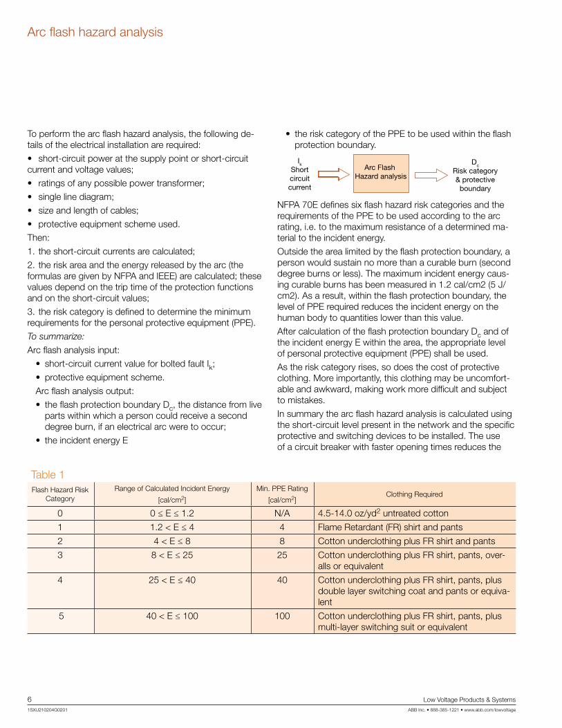
To perform the arc flash hazard analysis, the following de-tails of the electrical installation are required:
• short-circuit power at the supply point or short-circuit current and voltage values;
• ratings of any possible power transformer;
• single line diagram;
• size and length of cables;
• protective equipment scheme used.
Then:
1. the short-circuit currents are calculated;
2. the risk area and the energy released by the arc (the formulas are given by NFPA and IEEE) are calculated; these values depend on the trip time of the protection functions and on the short-circuit values;
3. the risk category is defined to determine the minimum requirements for the personal protective equipment (PPE).
To summarize:
Arc flash analysis input:
• short-circuit current value for bolted fault Ik;
• protective equipment scheme.
Arc flash analysis output:
• the flash protection boundary Dc, the distance from live parts within which a person could receive a second degree burn, if an electrical arc were to occur;
• the incident energy E
• the risk category of the PPE to be used within the flash protection boundary.
IkShortcircuitcurrent
Arc Flash Hazard analysis
Dc
Risk category& protectiveboundary
NFPA 70E defines six flash hazard risk categories and the requirements of the PPE to be used according to the arc rating, i.e. to the maximum resistance of a determined ma-terial to the incident energy.
Outside the area limited by the flash protection boundary, a person would sustain no more than a curable burn (second degree burns or less). The maximum incident energy caus-ing curable burns has been measured in 1.2 cal/cm2 (5 J/cm2). As a result, within the flash protection boundary, the level of PPE required reduces the incident energy on the human body to quantities lower than this value.
After calculation of the flash protection boundary Dc and of the incident energy E within the area, the appropriate level of personal protective equipment (PPE) shall be used.
As the risk category rises, so does the cost of protective clothing. More importantly, this clothing may be uncomfort-able and awkward, making work more difficult and subject to mistakes.
In summary the arc flash hazard analysis is calculated using the short-circuit level present in the network and the specific protective and switching devices to be installed. The use of a circuit breaker with faster opening times reduces the
Table 1Flash Hazard Risk
CategoryRange of Calculated Incident Energy
[cal/cm2]
Min. PPE Rating
[cal/cm2]Clothing Required
0 0 ≤ E ≤ 1.2 N/A 4.5-14.0 oz/yd2 untreated cotton
1 1.2 < E ≤ 4 4 Flame Retardant (FR) shirt and pants
2 4 < E ≤ 8 8 Cotton underclothing plus FR shirt and pants
3 8 < E ≤ 25 25 Cotton underclothing plus FR shirt, pants, over-alls or equivalent
4 25 < E ≤ 40 40 Cotton underclothing plus FR shirt, pants, plus double layer switching coat and pants or equiva-lent
5 40 < E ≤ 100 100 Cotton underclothing plus FR shirt, pants, plus multi-layer switching suit or equivalent

Low Voltage Products & Systems 7ABB Inc. • 888-385-1221 • www.abb.com/lowvoltage 1SXU210204G0201
Arc flash hazard analysis
amount of available energy, which reduces the cost of per-sonal protective equipment. The smaller amount of released energy, the more economical the PPE.
NFPA 70E and IEEE 1584 Standards provide the formulas for calculation of the flash protection boundary Dc and the incident energy E, which defines the minimum PPE require-ments. These formulas can be simplified as follows:
Dc = f(Ibf, t)
E = f(Ibf, t)
Ia = f(Ibf)
where:
• Ia is the current which flows in the electrical arc (which is lower than the bolted fault current), called arcing current;
• Ibf is the current calculated by short-circuit analysis, called the bolted fault current;
• t is the clearing time and is obtained by the trip curves corresponding to current Ia.
NOTE: t is the clearing time corresponding to Ia (arcing cur-rent), not the time corresponding to Ibf (bolted fault)
Once the incident energy has been calculated, the risk cat-egory is defined in Table 1.
The incident energy E depends on the tripping time of the protection device, which is dependent on its settings.
The choice of protection devices with fast tripping times reduces the incident energy and consequently the PPE category and the relevant costs.
However, this often clashes with the requirement for selec-tive coordination in which the tripping time is necessarily high, in order to clear the fault.
While the flash hazard analysis is performed primarily to determine the risk areas, it can also improve the choice of the protective and switching devices. The use of a circuit breaker with fast trip times reduces the incident energy, as the examples on the following pages demonstrate.

8 Low Voltage Products & Systems
1SXU210204G0201 ABB Inc. • 888-385-1221 • www.abb.com/lowvoltage
Minimize arc flash effects
The standards state that before working on electrical equip-ment, the equipment must be de-energized. This solution eliminates arc flash hazard but is sometimes difficult to apply.
To minimize the arc flash effects, it is necessary to limit the energy released so that personnel are not in harm’s way. Measures may be divided into passive measures and active measures. Passive measures limit the effects of the incident energy, such as distance and barriers. Active measures limit the incident energy level.
Passive measuresPassive measures can be barriers or procedures:
• Arc-proof switchgear: designed to direct the arc energy to vent out the top of the switchgear, and limit the en-ergy directed to the front;
• Remote control operation of protection and switching devices; keep personnel at a safe distance from the equipment;
• Closed door racking-in/out of the withdrawable circuit breakers: ABB Emax circuit breakers allow closed door operations and have their primary connections isolated by shutters;
• Remote or longer operating mechanisms so that racking-in/out operations can be carried out at a safe distance;
• Barriers between personnel and equipment during racking-in/out or opening/closing operations;
• Reduction of the short-circuit current by disconnection of unnecessary power supply sources: for example, disconnecting parallel transformers and opening bus ties;
• Remote control devices for racking-in/out of the circuit breaker at a safe distance.
Active measuresThe passive measures described above might not be ad-equate with a high available short-circuit current; limiting the time of the energy release becomes necessary. In order to reduce the released energy, the following measures can be taken:
• Circuit breakers with fast tripping times: a fast trip may clash with the selectivity requirements; typically the nearer to the supply source the circuit breaker is, the higher the trip times shall be set. Also, the higher the short-circuit power, the higher the requirement for service continuity, as in the main circuit breaker;
• Zone selectivity: this co-ordination type allows setting of a fast trip time only for the circuit breaker immediately upstream of the fault. Thus it is possible to achieve a high selective coordination while keeping a fast trip;
• Choosing ‘fast’ setting values for maintenance opera-tions only: the ‘dual setting’ function of the ABB Emax allows adoption of two different parameter sets. Nor-mally the settings can comply with the selectivity limits, trip thresholds and times. During maintenance opera-tions, a command can be sent to the trip unit so that it switches to the ‘fast’ setting mode and operates more safely.
In particular, with ABB circuit breakers it is possible to limit released energy by:
• Choosing protective devices with fast trip times; keep-ing in mind that shorter trip times may interfere with selectivity requirements;
• Using zone selectivity; zone selectivity allows the set-ting of a faster time only for the circuit breaker im-mediately upstream of the fault. Thus, it is possible to achieve a high level of selective co-ordination and keep fast tripping;
• Using dual settings: this function allows two different parameters to be set. Under normal conditions, the settings allow standard selectivity, trip thresholds and times. During maintenance, a command is sent to the trip unit so that it switches to the ‘fast’ setting and operates more safely.
The choice of the protective device depends on the sys-tem requirements. Circuit breakers equipped with high performance trip units (Table 2) allow a low risk category to be obtained and at the same time high selectivity levels.
Table 2
PR223EF(IEC only)
PR122 PR123 PR332 PR333
Zone selective ● ● ● ● ●
Dual setting — — ● — ●

Low Voltage Products & Systems 9ABB Inc. • 888-385-1221 • www.abb.com/lowvoltage 1SXU210204G0201
ABB Solutions
Here are some examples showing how the choice of protective devices and coordination type can affect the risk category.
Time-current selectivityIn the scheme below, thanks to the settings of the circuit break-ers, ‘economical’ time-current selectivity can be achieved.
Un = 480 Vu k = 5%
Ibf = 48.11 kA
E4
E3
E4H 3200 PR122/P-LSI In=3200A 4p:
L: I1: 0.85 t1: 102s
S: t=const I2: 5.4 t2: 0.14s
I: - off
E3N 2500 PR122/P-LI In=2500A 4p
L: I1: 0.80 t1: 36s
I: I3: 8.00
To achieve selectivity, function I of the upstream circuit breaker shall be set to OFF and a minimum time of 0.14s shall be set for function S.
By using the formulas of the standards, the following results are obtained:
Dc = 4.21ft = 1.29m
Ia = 23.30 kA
E = 8.83cal / cm2
With reference to Table 1, a PPE of category 3 shall be used.
This example shows that the choice of time-current selective co-ordination actually results in a cost increase because it requires a high PPE category.
Zone selectivityZone selectivity allows the fault area to be precisely identified and de-energized.
When current values exceed the protective setting, a block signal is sent to the upstream protective device and verifies that a similar block signal has not been sent to the downstream protection before tripping, insuring only the protective device on the supply side of the fault trips.
This selectivity allows faster tripping times than time-current selective coordination as it is unnecessary to increase the time delay closer to the supply source. The circuit breaker which does not receive the block signal trips quicker.
Applying zone selectivity to the previous example, the supply side circuit breaker (E4) trips in a short time (called selectivity time, adjustable from 0.04 to 0.2s) only if the fault occurs immediately on its load side, otherwise it remains blocked.
Time current curve1000s
100s
10s
1s
0.1s
E3
E4 1a lbf
1kA 10kA 100kA 1000kA

10 Low Voltage Products & Systems
1SXU210204G0201 ABB Inc. • 888-385-1221 • www.abb.com/lowvoltage
ABB Solutions
By setting the selectivity time at 0.07s, the following values are obtained:
Dc = 2.72ft = 0.83m
Ia = 23.30 kA
E = 3.67cal / cm2
Thanks to the faster tripping time, a PPE of category 1 is sufficient.
The use of zone selectivity allows a lower risk category solu-tion, while maintaining high selective coordination.
Dual settingsThe PR123 and PR333 trip units for Emax air circuit breaker can store two parameter sets A and B for each protective function. These two sets can be switched alternately by an external device. The switching command can be given whenever the installation requirements demand it (for ex-ample if the network configuration is modified) or for mainte-nance requirements of the switchboard.
The following example shows how the two parameter sets A and B can be adjusted so that set A can be used under normal conditions to achieve selective coordination and set B when maintenance operations are carried out on the switchboard to insure a fast trip time under fault conditions.
Time current curve1000s
100s
10s
1s
0.1s
1kA 10kA 100kA 1000kA
E3
E4 1a lbf
Zone selectivity

Low Voltage Products & Systems 11ABB Inc. • 888-385-1221 • www.abb.com/lowvoltage 1SXU210204G0201
ABB Solutions
E4H 3200 PR122/P-LSI In=3200A 4P
L: I1: 0.85 t1: 102s
S: t=const I2: 5.4 t2: 0.14s
I: off
E4H 3200 PR122/P-LSI In=3200A 4P
L: I1: 0.85 t1: 3s
S: t=const I2: 1.5 t2: 0.05s
I: off
Set A allows time-current selectivity, whereas Set B adopts the minimum setting values of the protection functions L and S and allows the following calculation:
Dc = 2.52ft = 0.77m
Ia = 23.30 kA
E = 3.15cal / cm2
The risk category is equal to 1.
Summary tableTime-current selectivity Zone selectivity Dual setting
Dc 1.29 m 0.83 m 0.77 m
E 8.83 cal/cm2 3.67 cal/cm2 3.15 cal/cm2
PPE Category 3 1 1
additional wiring NO YES NO
ABB trip unit required PR121 or PR122 or PR123PR122 or PR123 upstream and
downstreamPR123
Loss of coordination during maintenance operations
NO NO possible
Noteslong trip times for multi-tiered
selectivity chains
selectivity time needs to take into consideration any
downstream CB without zone selectivity
switching from set A to set B can be automatic and/or
remotely operated
Time current curve - Set A1000s
100s
10s
1s
0.1s
1kA 10kA 100kA 1000kA
E3
E4 1a lbf
Time current curve - Set B1000s
100s
10s
1s
0.1s
1kA 10kA 100kA 1000kA

12 Low Voltage Products & Systems
1SXU210204G0201 ABB Inc. • 888-385-1221 • www.abb.com/lowvoltage
Annex A: Arc flash hazard (mathematical approach)
A.1 Arc flash hazard analysisThe arc flash hazard analysis is the process to determine the risk category, the level of the PPE required and to define all the measures for minimizing personnel exposure to haz-ardous conditions. This analysis requires knowledge of the short-circuit currents and the clearing time of the protective devices used or to be used.
The necessary formulas to perform this analysis are below.
A.2 Calculation of the flash protection boundary Dc (NFPA 70E 130.3(A))The flash protection boundary, indicated by Dc, is the dis-tance from exposed live parts within which a person could receive a second-degree burn if an electric arc flash were to occur. It can be set at a certain value under standard condi-tions or it can be calculated.
NFPA70E states that the flash protection boundary Dc can be fixed at 4 ft (1.22 m) under the following conditions:
• Un ≤ 600 V;
• Ibf = 50 kA (bolted fault) of 50 kA;
• Tripping time of 6 cycles (0.1s at 60 Hz);
This boundary can also be calculated using the combination ‘current x cycle’ of a 300 kA cycle (in this example a 20 kA fault extinguished in 0.25 s, which corresponds to 15 cycles at 60 Hz).
When the current-quenching time combination exceeds a 300 kA cycle, the flash protection boundary Dc can be calculated by using the following formulas:
Dc = √2.65•MVAbf•t or Dc = √53•MVA•t
where:• MVAbf is short-circuit power for the bolted fault at the
analysis point in MVA;
• MVA is the transformer power1 (for transformers with power lower than 0.75 MVA, it is necessary to multiply the transformer power by 1.25);
• t is the clearing time of the protective device in s.
A.3 Calculation of the incident energy E (IEEE 1584)The energy released by the electric arc depends on the current flowing through the fault. In turn, the current flowing through the electric arc, named arcing current Ia, depends on the bolted fault current. Generally speaking, Ia is lower than Ibf due to the arc impedance.
1 NFPA 70E considers the short-circuit voltage of the transformers equal to 5%.
IEEE 1584 gives the formula to calculate the arcing current Ia; for voltage values lower than 1000V:
Log(Ia)=K+0.662•Log(Ibf)+0.0966•U+0.000526•G+0.5588•U•
Log(Ibf)-0.00304•G•Log(Ibf)
Ia = 10Log(Ia)
where:
• Ia is arcing current in kA;
• K is a constant equal to :
-0.153 for open systems;
-0.097 for enclosed systems;
• Ibf is the short-circuit current rms value in kA for bolted fault;
• U is the rated voltage of the system in kV;
• G is the distance between the conductors in mm, see Table 4 of IEEE 1584;
Once the current Ia is known, the tripping time of the pro-tective device can be determined. This time depends on the protective device used and is derived from the trip curves given by the manufacturer in correspondence with the arc-ing current, and not with the bolted fault current.
To determine the incident energy, first calculate the normal-ized incident energy En at a distance of 24” (610mm) for an arc lasting 0.2 s:
Log(En)=K1+K2+1.081•Log(Ia)+0.0011•G
En=10Log(En)
where:
• En is the normalized incident energy in J/cm2;
• K1 is a constant equal to:
-0.792 for open systems;
-0.555 for enclosed systems;
• K2 is a constant equal to:
0 for ungrounded or high resistance ground sys-tems;
-0.113 for solidly grounded systems;
• G is the distance between the conductors in mm, see Table 4 of IEEE 1584;
Once the normalized incident energy is known, it is possible to calculate the incident energy E:
E=4.184•Cf•En•( t )•(610)x
0.2 D

Low Voltage Products & Systems 13ABB Inc. • 888-385-1221 • www.abb.com/lowvoltage 1SXU210204G0201
where:
• E is the incident energy in J/cm2;
• Cf is a factor equal to:
1 for Voltages exceeding 1 kV;
1.5 for Voltages less than or equal to 1 kV;
• En is the normalized incident energy in J/cm2;
• t is the tripping time of the protective device;
• D is the distance from the arc in mm;
• x is a factor depending on the distance between the conductors (see Table 4 of IEEE 1584).
The trip time is read from the time-current curves of the protective devices. The calculated short-circuit current (Ibf) and the relevant arcing current Ia are important as differ-ent values can affect the incident energy significantly. As a result, both the maximum and minimum values of these currents need to be considered and all the figures obtained must be evaluated carefully. A lower short-circuit current may even cause the circuit breaker to trip slower so that the incident energy released is higher than that released by a greater fault current. Therefore, the calculation is performed by considering both 100% as well as 85% of the Ia and the worst results are considered (this is especially critical for fuses, whose trip times at 100% and at 85% of a specific fault current can be quite different).
Annex A: Arc flash hazard (mathematical approach)
The distance D from the arc, at which the energy is calcu-lated, is the distance to the face and chest of the human body, not to the arms and hands. Table 3 of IEEE 1584 (page 9) gives the distances according to type of equipment involved.
A.4 Simplified formulas IEEE 1584 (5.7 Low-volt-age circuit breakers)IEEE 1584 (5.7 Low-voltage circuit breakers) gives simplified formulas for calculation of incident energy and of the flash boundary for LV circuit breakers. These formulas do not require the use of time-current curves and are applicable when the following is true:
• working distance 460 mm;
• short time delay
• 700 ≤ Ibf ≤ 106000
• I1 ≤ Ibf ≤ I2 where:
I1 is the current causing the instantaneous tripping of the circuit breaker
I2 is the breaking capacity of the circuit breaker
With current values lower than I1, the incident energy in-creases very quickly as the fault current decreases.
Table 3: Simplified formulas≤480 V 575 - 635 V
Rating Breaker type Trip unit typeIncident energy
[J/cm2]
Flash boundary
[mm]
Incident energy
[J/cm2]
Flash boundary
[mm]
100-400 MCCB TM or M 0.189•Ibf+0.548 9.16•Ibf+194 0.271•Ibf+0.180 11.8•Ibf+196
600-1200 MCCB TM or M 0.223•Ibf+1.590 8.45•Ibf+364 0.335•Ibf+0.380 11.4•Ibf+369
600-1200 MCCB E, LI 0.377•Ibf+1.360 12.50•Ibf+428 0.468•Ibf+4.600 14.3•Ibf+568
1600-6000 MCCB or ICCB TM or E, LI 0.448•Ibf+3.000 11.10•Ibf+696 0.686•Ibf+0.165 16.7•Ibf+606
800-6300 ACB E, LI 0.636•Ibf+3.670 14.50•Ibf+786 0.958•Ibf+0.292 19.1•Ibf+864
800-6300 ACB E, LS 4.560•Ibf+27.230 47.20•Ibf+2660 6.860•Ibf+2.170 62.4•Ibf+2930
These formulas have been calculated using circuit breakers from different manufacturers and are meant to give the ‘worst case’ maximum energy values and arc flash boundary.
Of course, more accurate calculations can be obtained by using the specific tripping curves provided by the circuit breaker manu-facturers.

14 Low Voltage Products & Systems
1SXU210204G0201 ABB Inc. • 888-385-1221 • www.abb.com/lowvoltage
Annex A: Arc flash hazard (mathematical approach)
A.5 Numerical exampleAn electrician is sent to rack out a 480V circuit breaker; the breaker has provisions for closed door racking. What Personal Protective Equipment (PPE) is required?
This example analyzes the arc flash hazard by assuming a voltage of 480V and the circuit breaker racking out.
Transformer data:
• 2000 kVA
• 13.8kV/480V
• 2400 A
• 5% Z
Circuit breaker data:
• Emax E4S-A 3200A 65 kA
From the formula of NFPA 70E:
Dc=√53•MVA•t=√53•2•0.07=2.72ft=0.83m
(tripping time is assumed to be 70ms)
The arcing current is:
Log(Ia)=K+0.662•Log(Ibf)+0.0966•U+0.000526•
G+0.5588•U•Log(Ibf)-0.00304•G•Log(Ibf)
with:
• K=-0.097 (fault inside switchgear)
• Ibf=2,000,000•100=48.11 kA
√3•480•5
• U=480 V
• G=32mm=1.25”
Then:
Log(Ia)=1.3674⇒Ia=101.3674=23.30 kA
The normalized incident energy En is equal to:
Log(En)=K1+K2+1.081•Log(Ia)+0.0011•G
0.2 D
with:
• K1=-0.555 (fault in enclosed system)
• K2 = -0.113 (system grounding)
• Ia = 23.3 kA
• G = 32mm = 1.25”Then:
Log(En)=0.8453⇒En=7j/cm2
The incident energy E shall be:
E=4.184•Cf•En•( t )•(610)x
with
• Cf = 1.5 (voltage lower than 1 kV)
• En = 7 J/cm2
• t = 0.07s
• D = 610 mm (typical distance in compliance with Table 3 of IEEE 1584)
• x = 1.473
Therefore:
E=15.30J/cm2=3.67cal/cm2
A PPE of category 1 allows the released energy to be reduced to a value lower than 1.2 cal/cm2.
Please note that a trip time of 0.1s would result in energy of 5.25 cal/cm2 requiring PPI category 2. The correct setting of the circuit breaker causes a sig-nificant reduction in the released energy and conse-quently the costs of using the appropriate PPE.
The following graphs show risk categories which can be obtained with an ABB Emax air circuit breaker and an ABB Tmax molded-case circuit breaker. From the figures, the risk category results are dependent on the current thresholds and on the times set for the protection functions.

Low Voltage Products & Systems 15ABB Inc. • 888-385-1221 • www.abb.com/lowvoltage 1SXU210204G0201
Annex A: Arc flash hazard (mathematical approach)
Time current curve
100s
10s
1s
0.1s
1kA 10kA 100kA 1000kA0.01s
Non-con�gurabletripping time
Con�gurabletripping time
EMax = 27.45 cal/cm2 Category 4Emin = 1.62 cal/cm2 Category 1
(Ibf=80 kA)
E=3.13cal/cm2 Category 1(Ibf=125 kA
Emax E3 3200
Time current curve
100s
10s
1s
0.1s
1kA 10kA 100kA0.1kA
0.01s
Tmax T5 400
Con�gurabletripping time
Non-con�gurabletripping time
EMax = 2.03 cal/cm2 Category 1Emin = 0.20 cal/cm2 Category 0
(Ibf=6 kA)
E=0.26cal/cm2 Category 0(Ibf=60 kA

16 Low Voltage Products & Systems
1SXU210204G0201 ABB Inc. • 888-385-1221 • www.abb.com/lowvoltage
Notes

Low Voltage Products & Systems 17ABB Inc. • 888-385-1221 • www.abb.com/lowvoltage 1SXU210204G0201
Notes

18 Low Voltage Products & Systems
1SXU210204G0201 ABB Inc. • 888-385-1221 • www.abb.com/lowvoltage
Notes

Low Voltage Products & Systems 19ABB Inc. • 888-385-1221 • www.abb.com/lowvoltage 1SXU210204G0201
Notes

20 Low Voltage Products & Systems
1SXU210204G0201 ABB Inc. • 888-385-1221 • www.abb.com/lowvoltage
Notes


ABB Inc.Low Voltage Control Products & Systems1206 Hatton RoadWichita Falls, TX 76302Phone: 888-385-1221 940-397-7000Fax: 940-397-7085
USA Technical help: 888-385-1221, Option 4 7:30AM to 5:30PM, CST, Monday - Friday
Find USA Authorized Distributors www.abb.us/lowvoltage
1SXU
2102
04G
0201
Nov
embe
r, 20
09
Contact us