Embed Size (px)
Citation preview
.Low Modulus Pavement on Elastic Foundation JON HAGSTROM, RICHARD E. CHAMBERS, and EGONS TONS
Respectively, Research Assistant, Senior Research Engineer, and Assistant Professor of Civil Engineering, Department of Civil Engineering, Massachusetts Institute of Technology
The Westergaard theory for a plate on a "heavy liquid foundation" has been applied to the analysis of stresses and deflections in the asphalt-bound layer(s) of a flexible pavement system. A computer program has been developed to give a solution for the symmetrical loading case. Plots of the bending stresses, shear stresses and vertical deflection vs pavement thickness have been made to determine the influence of the various parameters involved in the analysis. It was found that the bending and shear stresses depend on the ratio of the pavement stiffness to the support stiffness, whereas the deflection is determined by the stiffness ratio and the magnitude of the modulus of support reaction.
A limiting stiffness ratio of EI k ~ 100 was chosen as a criterion for plate-type behavior in the asphalt-bound layer. This limit, howeve .t, w~s nc1t rigorously determined. Certain limitations as to thickness for given values of the other variables were discovered. Relatively thin asphalt-bound layers give little load spreading action because of their high flexibility. The load is transferred directly to the support, causing large vertical deformations in the support layer. The behavio1· of very thick asphalt-bound layers approaches that of a single homogeneous layer. Slresses are dependent only on load, and plate theory no longer applies. A computer program for stress-deflection calculations is applied.
•A TYPICAL flexible pavement cross-section may include the natural in-place subgrade, a compacted subgrade, a compacted subbase, a compacted base of treated or plain gravel or crushed rock, and a surface of one or more layers of aspbaltic concrete. This vertical variation in the material corilposition of the highway structure coupled with the complex nature of the behavior under load of the individual materials, has hindered the development of rational analysis for the stresses and displacements produced by tJ:affic loads.
In 1943, Burmister (1) introduced a theory of stresses and displacements in layered systems based on the assumption that the materials of each layer are ideally elastic. Burmister's analysis provides an exact solution for a given surface loading. The equations are rather cumbersome to work with in practice; however, computer solutions have been developed for a large range of applications (5).
Attempts to correlate theoretical stresses and deflections with actual soil behavior by using Burmister's theory have met with little success. Sowers and Vesic (6) found that the reduction in subgrade stresses predicted by Sunnis er's theory occurs only when the stiffer top layers bave the ability to develop tensile stresses. In general, investigators have concluded that soil properties cannot be accurately described in terms of a single Young's modulus and Poisso11's ratio as is assumed in elastic theory.
Paper sponsored by Committee on Flexible Pavement Design and pre sented at the 44th Annual Meeting .
172
173
When the surface layer is fairly stiff in comparison with the support and the deflections are small, the tensile stresses produced in the support will be negligible. Assuming that these conditions are satisfied and that the behavior of the surface layer is consistent with elastic theory, Burmister's equations can be used for the analysis of stresses and deflections in the asphalt-bound layer.
By making certain simplifying assumptions concerning the behavior of the asphaltbound and supporting layers, the equations for the stresses and displacements can be reduced to a manageable form. This simplified theory was first suggested by Westergaard (7) for use in the design of concrete pavements. It is the purpose of this paper to explore-Westergaard's theory as it applies to the analysis of stresses and deflections in the surface layer of a flexible pavement system. The term "surface layer" used in this context is meant to include the asphalt-bound layer(s) only. The treatment in this report is mathematical in nature. It is intended as background material for future research which will include a treatment of asphaltic concrete properties for various timetemperature and loading conditions.
ELASTIC APPROACH
The behavior of asphaltic concrete is not consistent with several of the assumptions of elastic theory . The relation between stress and strain is not, in general, linear; moreover, it is time dependent. However, under certain conditions a flexible pavement will exhibit nearly complete rebound on removal of load, the recovery occurring over some time interval. The amount of deflection under load and the time for recovery on removing the load will depend on the temperature of the pavement a11d the duration of the load. Baker and Papazian (10) bave pointed out thal the effect of choosing a particular temperature and time of loading to determine the elastic modulus of the asphaltbound material is equivalent to selecting a secant modulus. The complexity of the mathematics for rigorous treatment of the viscoelastic theory makes the use of this secant modulus artifice and elastic theory necessary at this time.
APPLICATION OF WESTERGAARD THEORY
Development
Westergaard treats the asphalt-bound layer as a circular plate of infinite extent. The flexural rigidity of the plate can be expressed as:
where
D=~ 1 - µ2
E modulus of elasticity for plate {J?si), I = moment of inertia for plate (in. ), and µ = Poisson's ratio.
For a plate of constant thickness, this equation becomes:
Eh3
D = -=-12::-7:( 1=---__,µ 2'""'")
(1)
(2)
where his the thickness of plate in inches. The deflection of a pavement depends not only on its flexural rigidity but also on the stiffness of the support beneath. Westergaard has expressed the stiffness of the support as a modulus of support reaction, k. The modulus is defined mathematically as follows:
k = 12.. = reaction of support w deflection of support surface (3)
174
34
32
30
28
26
24
'?22
}20 ; IB Vi ~ 16
~ 14 0:
"o 12
~ 10
0: 8
6
4
0
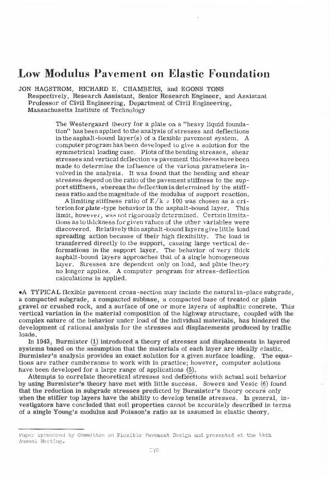
Supporl modulus" 250 pci Poisson's ratio =0.5 E-Yountfs modulus, psi
3 4 5 6 Thickness, H ( inJ
9 Kl II 12
Figure 1. Radius of relative stiffness vs thickness oi asphalt-botmr.1 1H.y...,, · .
34
32
30
28
26
~ 24 ~
,,;
~ 22
Vi 20 . 18
0 • 16 0:
0 ~ 14 , :g
12 0:
10
8
6
4
2
0
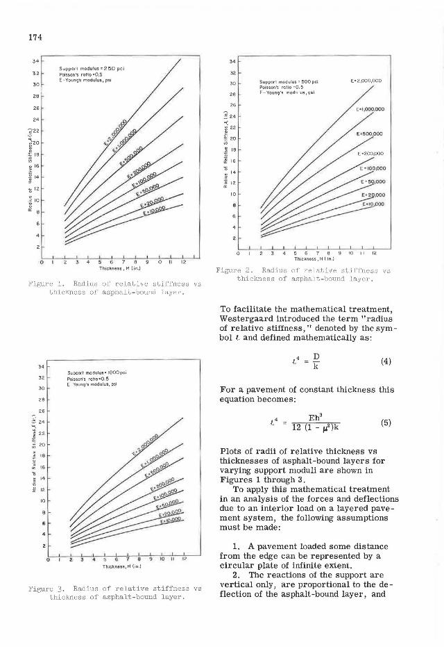
Supporl modulul"' 1000 pci Poisson's rotio•O !5 E -Young's modulus, psi
2 3 6 7 8 9 10 II 12
Thickness, H (in l
Figure 3. Radius of relative stiffness vs thickness of asphalt - bound layer .
34
32
30
28
26
:§ 24 ~-
5 22
~ 20
"' ~ ji
18
~ 16
'O 14 ,
:g 12 0:
10
8
6
4
?.
0
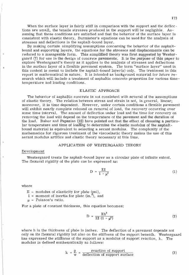
Supporl modulus" 500 pci Poisson's ratio =0.5 E-Young's modulus.psi
E• 2,000,000
4 5 6 7 8 9 10 I l 12 Thickness, H ( in.)
Figure 2. Radius of relative stiffness vs thickness of asphalt-bound layer.
To facilitate the mathematical treatment, Westergaard introduced the term "radius of relative stiffness," denoted by the symbol .t and defined mathematically as:
4 D .{. = k (4)
For a pavement of constant thickness this equation becomes:
Eh3
.t4
= 12 (1 - 1.i2)k (5)
Plots of radii of relative thickness vs thicknesses of asphalt-bound layers for varying support moduli are shown in Figures 1 through 3.
To apply this mathematical treatment in an analysis of the forces and deflections due to an interior load on a layered pavement system, the following assumptions must be made:
1. A pavement loaded some distance from the edge can be represented by a circular plate of infinite extent.
2. The reactions of the support are vertical only, are proportional to the de -flection of the asphalt-bound layer, and
175
are independent of the loaded area. The latter portion of this assumption is equivalent to assuming that there is no transfer of stress through shear resistance in the support analogous to the behavior of a "heavy liquid."
3. The asphalt-bound layer is at every point in contact with the support. 4. Volumetric changes, variations in support properties, temperature, horizontal
components of support reaction, and dynamic effects can be neglected or accounted for otherwise.
Support
Because the support, consisting of particulate materials, is neiU1er a perfectly elastic solid nor a heavy liquid, it is necessary to evaluate the support modulus, k by some ·sort oI plate bearing test. This necessitates the adoption of some standard plate size and testing procedure. Work by the U. S. Bureau of Public Roads (11) indicates that for circular plates with diameters between 26 and 84 in. there is little variation in the pressure required to produce a given deflection. Furthermore, Terzaghi (12) has indicated that a linea.r relationship behveen deflection and pressure does exisITor some soils up to one-half the bearing capacity of the soil. This justifies the assumption of linearity between reaction and deflection and negligible transfer of stress by shear resistance in the soil within the limits indicated.
Asphalt-Bound Layer
Westergaard represents the asphalt-bound layer as a circular plate of infinite extent. He assumes that the properties of the asphalt-bound material are consistent with the assumptions of elastic theory (13); that is, the material must be continuous, homogen ous isolropic and governed bYff ooke' s law.
By requiring equilibrium of forces and moments in the three directions of space, a system of six equations with six unknowns can be derived. These six equations can be reduced to a single sixth-order differential equation describing the behavior of an ideally elastic body under load. For a body whose dimension in the vertical direction is much smaller han in the two other directions, the governing sixth-order differential equation can be reduced to the familiar fourth-order differential equation of ordinary plate theory by making several simplifying assumptions:
1. The middle plane of the plate remains unstrained under load. 2. Plane sections remain plane under load. 3. The direct stress in the vertical direction is small in comparison with the other
stress components and can be neglected in the stress-strain relations. 4. A plane section normal to the middle plane before loading remains normal under
load.
The last assumption is equivalent to stating that the deformation due to vertical shearing stresses is very small and can be i1eglected.
H the behavior of the asphalt-bound layer under load is to be consistent with plate theory the asphalt-bou11d layer must be relatively .rigid in comparison with the support layer. However, it is difficult to define the critical E/k value because of the many assumptions involved.
A critical ratio of E /k = 100 is proposed in this paper with the following reasoning:
1. Plate theory requires that the thickness of the plate be small in comparison with the dimensions in the other two directions. For circular plates, it is commonly required that the thickness-radius ratio be greater than 10 (26).
2. The radius of influence of a concentrated load is approximately 4t, where t depends on the E/k ratio and the asphalt-bound layer thickness (14).
3. For values of E/k less than 100 the radius of influence ofi concentrated load is at best seven times greater than the asphalt-bound layer thiclmess.
176
Because the critical ratio has not been rigorously determined, it should be used only as a general guide. However, it is important to realize that the Westergaard theory becomes increasingly inaccurate as the stiffness of the asphalt-bound layer approaches that of the support. Thus, the application of the theory is limited to conditions which lead to small deUections the vertical stress at the pavement support interface should not exceed one-half the ultimate bearing stress of the support and the E/k ratio should be 100 or greater.
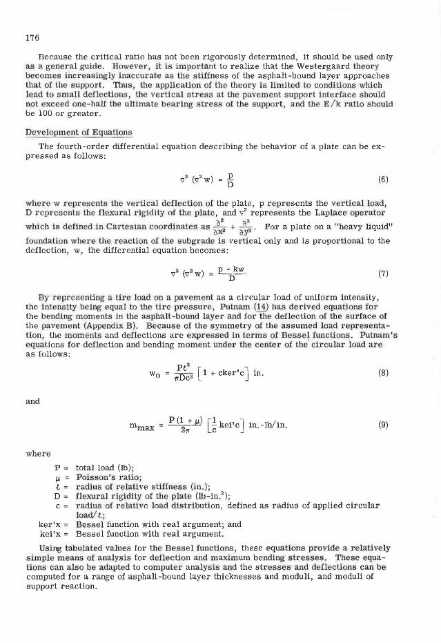
Development of Equations
The fourth-order differential equation describing the behavior of a plate can be expressed as follows:
(6)
where w represents the vertical deflection of the plate, p represents the ve1·tical load, D reprcscuts the flexural rigidity nf the plate, and v2 represents the Laplace operator
02 2 which is defined in C:u:tesian coordinates as - 2 + _Q_2 • For a plate on a "heavy liquid"
(I X oY foundation where the reaction of the subgrade is vertical only and is proportional to the deflection, w, the differential equation becomes:
(7)
By representing a. tire load on a pavement as a circular load of uniform intensity, the intensity being equal to the tire pressure Putnam (14) has derived equations for the bending moments in the asphalt-bound layer and for the deflection of the surface of the pavement (Appendix B). Because of the symmetry of the assumed load representation the moments and deflections are expressed in terms of Bessel functions. Putnam's equations for deflection and bending moment under the center of the' circular load are as follows:
2
w0 = :;c2 [ 1 + cker'c J in. (8)
and
mmax p (~: µ) [i kei'c J in.-lb/in. (9)
where
P = total load (lb); µ. = Poisson's ratio· t = radius of relative stiffness (in.); D = flexural rigidity of the plate (lb-in.2
);
c = radius of relative load distribution, defined as radius of applied circular load/ .t.;
ker'x = Bessel function with real argument; and kei'x = Bessel function with real argument.
Using tabulated values for the Bessel I-unctions, these equations provide a relatively simple means of analysis for deflection and maximum bending stresses . These equations can also be adapted to computer analysis and the stresses and deflections can be computed for a range of asphalt-bound layer thicknesses and moduli, and moduli of support reaction.
177
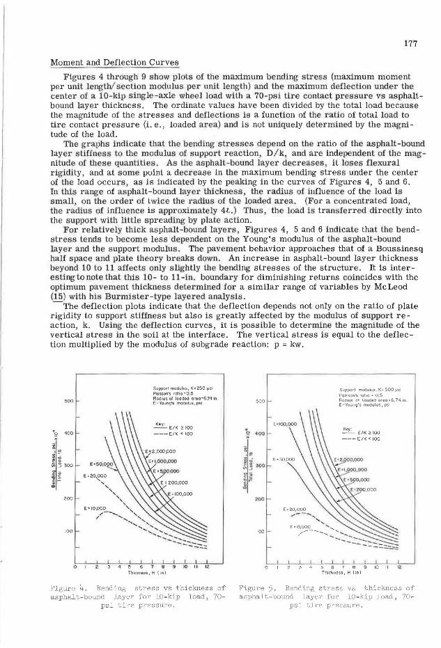
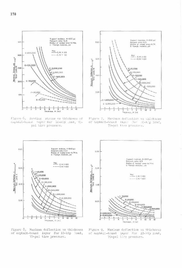
Moment and Deflection Curves
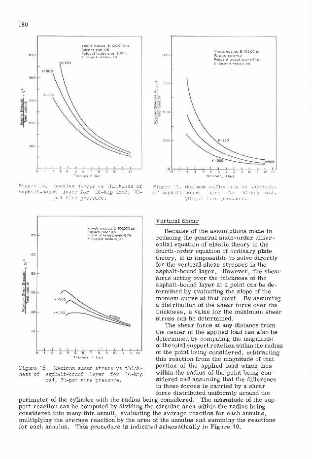
Figures 4 through 9 s how plots of the maximum bending stress (maximum moment per unit length/ section modulus per unit length) and the maximum deflection under the center of a 10- kip single-axle wheel load with a 70-psi tire contact pressure vs asphaltbound layer thickness. The ordinate values have been divided by the total load because the magnitude of the stresses and deflectioilS is a function of the ratio of total load to tire contact pressure (i.e., loaded area) and is not uniquely determined by the magnitude of the load.
The g1·ap.hs indicate that the bending stresses depend on the ratio of the asphalt-bound layer stiffness to the modulus of support reaction D/k and are indepe·ndent of the magnitude of these quantities. As the asphalt-bound layer decreases it loses flexural rigidity, and at some point a decrease in the maximum bending stress under the center of the load occurs, as is indicated by the peaking in the curves of Figures 4, 5 and 6. In tl1is range of asphalt-bound layer thickness, the radius of i11fluen·ce of the load is small, on th.e order of twice the radius of the loaded area. (For a concentrated load, the radius of influence is approximately 4.i. ) Thus , the load is transferred directly into the support with little spreading by plate action.
For relatively thick asphalt-bound layers, Figures 4, 5 and 6 indicate that the bendstress tends to become less dependent on the Young's modulus of the asphalt-bound layer and the support modulus . The pavement behavior approaches that of a Boussinesq half space and plate theory breaks down. An increase in asphalt-bound layer thickness beyond 10 to 11 affects only slightly the bending stresses of the structure. It is interesting to note that this 10- to 11 - in. boundary for diminishing returns coincides with the optimum pavement thickness determined for a similar range of variables by McLeod (15) with his Burmister-type layered analysis. -The deflection plots indicate that the deflection depends not only on the ratio of plate
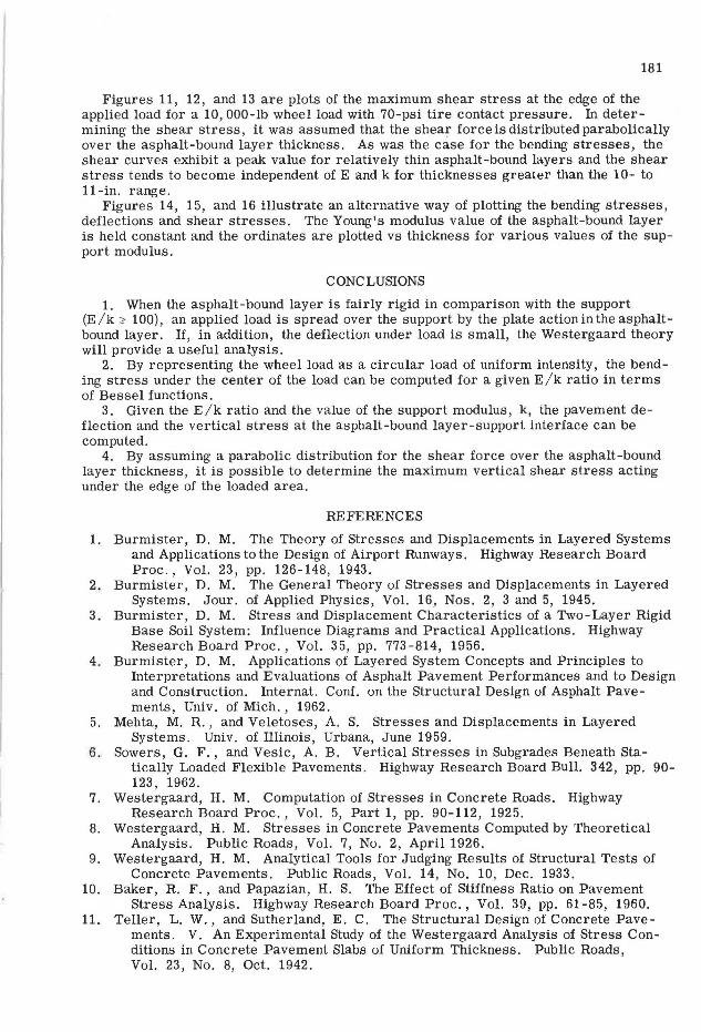
rigidity to support stiffness but also is greatly affected by the modulus of support reaction, k. Using the deflection curves, it is possible to determine the magnitude of the vertical stress in the soil at the interface. The vertical stress is equal to the deflection multiplied by the modulus of subgrade reaction: p = kw.
500
'<tQ 400
200
100
0 '
Support modulus, K• 250 pci Poisson's rolio =O 5 Rodius of loaded oreo=6.74 in E ~ Young's modulus, psi
~E/K ~100 ---E/K < 100
3456709 101112 Thlckness, H { in l
Figure 4. Bending stress vs thickness of asphalt-bound layer for 10-kip load, 70-
psi tire pressure.
500
200
100 -
0
E= 20,000 ,,,,,.--- ..... .... ,
E=I0,000 ',
Support modulus, K= 500 pci Poisson's rallo = 0 5 Radius of loaded area =6 74 in E- Young's modulus, psi
~ E/K~IOO --- E/K < 100
,,,..------ ................ _ ..... _ ---
----::::.::.::._":...-;;:
2 34567891011 12 Thickness, H (in)
Figure 5. Bending stress vs thickness of asphalt-bound layer for 10-kip load, 70-
psi t i re pressure.
178
500
100 -
0
Support modulus, K" 1000 pci Poisson's ratio = 0 .5 Radius of loaded orso = 6 74in E -Young's modulus, psi
Key: --EIK ~ IOO ---E/K < 100
56 891011 1:! Thickness, H (In l
Figure 6. Bending stress vs thickness of aspho.1C-'uuwn1 ln.yer fr)r lu-kip J.oad, ·ro
psi tire pressure .
o eo
" !2 015
00~
0
Support rf'IOdulu~, 1{•500 pci Poisson's ratio z0 .5 Radius of loaded area• 6 74 in f-Younits modulus, psi
Key: --E/K~IOO
---E/K < 100
Thickness, H l 1n )
Figure 8. Maximum deflection vs thickness of asphalt-bound layer for 10-kip load,
70-psi. tire pressure.
020
<t 0 ,15 0
0 .05
0
Support mod~lus, K"250 p(a Alisson's rolio =0.5 Aodiu:i; of loaded area "'6.74 E- Young's modulus, psi
~E/K 2: 100 ----E/K < 100
Thickness, H (in)
Figure 7. Maximtun deflection vs thickness of et3phalt-bound layer ful' 10-kip load,
70-psi tire pres sure.
.. Q
0 20
>< 0 15
005
0
Support modulus, K• IOOO pci Poisson's rolio:Q ,5 Radius of loaded oreo : 6 74 m E-Young's modulus, ps1
Key; -- E/K ~100 --- E/K < 100
6 9 10 H 12 Thicknesc;, H (in)
Figure 9. Maximum deflection vs thickness of asphalt-bound layer for 10-kip load,
70-psi tire pressure.
Deflected asphalt-bound layer Cir cular load of unifofm intensity
Pi-cir. •:1: P;
Xl<X2:5R
TT Wl
Support reaction under thin a·nnulus of deflected asphalt-bound layer
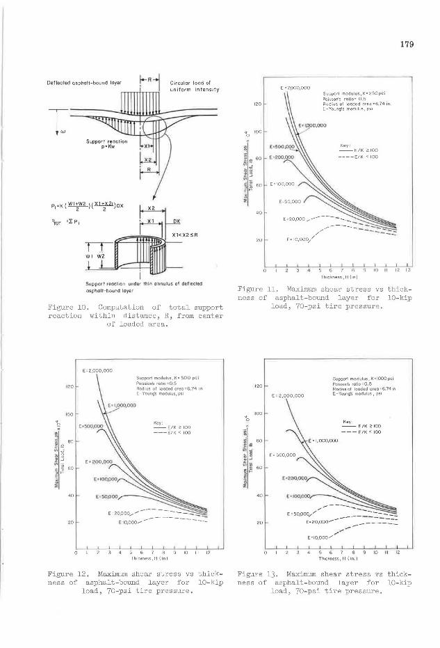
Figure 10. reaction
Computation of total support within distance, R, from center
of loaded area.
120
100
Q H
L BO
;, ~ ~ g i ...J
"' 0 60 e o
, I-
I 40
20
E=2,000,000
0
Suppor1 modulus, K• 500 pci Po1ssion's rotio :-Q 5 Rodius of looded oreo =-6.74 in E - Younq·s modulus, psi
Key : --E/K ~ 100 ---E/K < 100
10 11 12 Thickness, H (in)
Figure 12. Maximum shear stress vs n ess of asphalt-bound layer for
load, 70-psi tire pressure.
thick-10-kip
120
<t 100 Q
~ !;! "'. BO
i! "' ;; 60 , ;; E ,_ g
"' 40
20
E '2poo,ooo
E• 10,000//
0
Supporl modulus,K=250pci Poisson's rolio= 0 5 Radius of \coded area =6 74 in E-Young's modulus, psi
Key~
--E/K 2::100
----E/K < 100
---/,,..,,,...----- -:::.:::.::
179
9 10 II 12 13
Th1ckness,H (in)
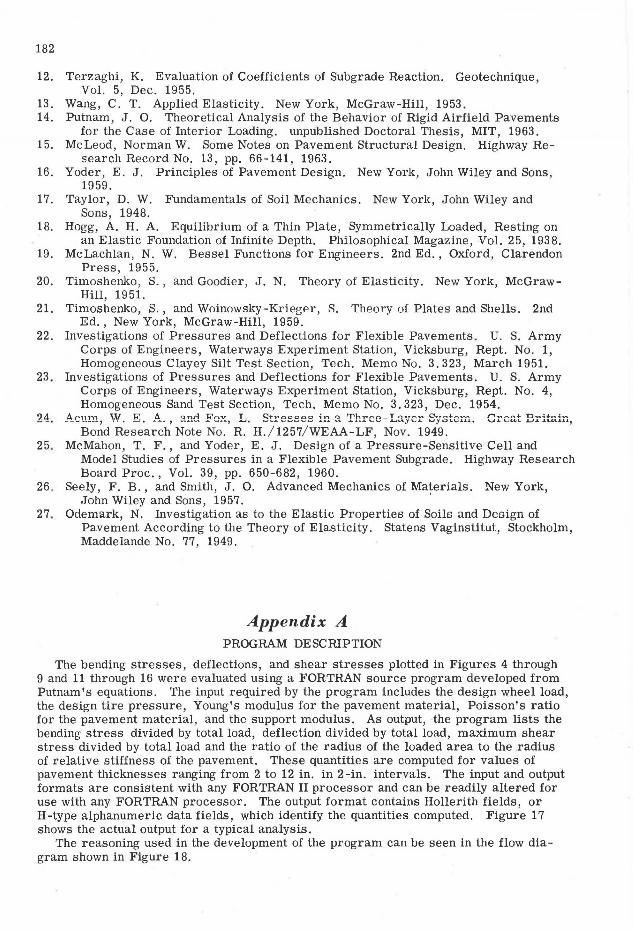
Figure 11. Maximum shear stress vs thickness of asphalt-bound layer for 10-kip
load, 70-psi tire pressure .
120
IOO
" 0
-, L. BO
~1 l: ...J ~u
60 ~~ E
}, 40
20
E • 2,000,000
4
Supporl modulus, K• 1000 pci Poisson's ratio= 0 5 Rodiusof looded oreo •6.741n E -Young·s modulus, psi
Key : -- E / K ~ 100
--- E/ K < 100
10 Thickness, H ( in.)
12
Figure 13. Maximum shear stress vs ness of asphalt-bound layer for
l oad, 70-psi tire pressure.
thick-10-kip
180
" Q
500
400
ij,, 300 . -; ..;
iii§ _£~
l ~ 200
100
0
Young's modulus, E= 100,000 psi Poisson's rolio=0,5 Radius of loaded area= 6 74 in K-Support modulus, pci
2 3 4 5 6
Thickness,H (m,)
10 11 12
Figure l4. Bending stress vs thickness of asphalt-bound layer for lO-kip load, 70-
psi tire pressure.
120
100
4 Q
20
Q
Young's modulus,E=I00,000 psi Poisson's ratio"' 0 5 Radius of loaded area "6.74 K-Support modulus, pci
9 10 II 12 13
Thickness, H (in)
Figure l6. Maximum shear stress vs thickness of asphalt-bound layer for lO-kip
load, 70-psi tire pressure.
0.20
" Q 015
005
Young's modulus, Ezl00,00 psi Poisson's rat10=04 5 Radius of loaded area= 6 74 in, K - Support modulus, pc1
· 0 0·.___.__.___,3~~.~5'---'---'----J'---i9~1Lo-----'11~L12-----'13--'
Thickness, H (in)
Figure l5. Maximum deflection vs thickness of asphalt-bound layer for lO-kip load,
70-psi tire pressure.
Vertical Shear
Because of the assumptions made in reducing the general sixth-order differential equation of elastic theory to the fourth-order equation of ordinary plate theory, it is impossible to solve directly for the vertical shear stresses in the asphalt-bound layer. However, the shear force acting over the thickness of the asphalt-bound layer at a point can be determined by evaluating the slope of the moment curve at that point. By assuming a distribution of the shear force over the thickness, a value for the maximum shear stress can be determined.
The shear force at any distance from the center of the applied load can also be determined by computing the magnitude of the total support reaction within the radius of the point being considered, subtracting this reaction from the magnitude of that portion of the applied load which lies within the radius of the point being considered and assuming that the difference in these forces is carried by a shear force distributed uniformly around the
perimeter of the cylinder with the radius being considered. The magnitude of the support reaction can be computed by dividing the circular area within the radius being considered into many thin annuli, evaluating the average reaction for each annulus, multiplying the average reaction by the area of the annulus and summing the reactions for each annulus. This procedure is indicated schematically in Figure 10.
181
Figures 11, 12, and 13 are plots of the maximum shear stress at the edge of the applied load for a 10, 000-lb wheel load with 70-psi tire contact pressure. In determining the shear stress, it was assumed that the shear force is distributed parabolic ally over the asphalt-bound layer thickness. As was the case for the bending stresses, the shear curves exhibit a peak value for relatively thin asphalt-bound layers and the shear stress tends to become independent of E and k for thicknesses greater than the 10- to 11-in. range.
Figures 14, 15, and 16 illustrate an alternative way of plotting the bending stresses, deflections and shear stresses. The Young's modulus value of the asphalt-bound layer is held constant and the ordinates are plotted vs thickness for various values of the support modulus.
CONCLUSIONS
1. When the asphalt-bound layer is fairly rigid in comparison with the support (E/k <o 100), an applied load is spread over the support by the plate actionintheasphaltbound layer. If, in addition, the deflection under load is small, the Westergaard theory will provide a useful analysis.
2. By representing the wheel load as a circular load of uniform intensity, the bending stress under the center of the load can be computed for a given E/k ratio in terms of Bessel functions.
3. Given the E /k ratio and the value of the support modulus, k, the pavement deflection and the vertical stress at the asphalt-bound layer-support interface can be computed.
4. By assuming a parabolic distribution for the shear force over the asphalt-bound layer thickness, it is possible to determine the maximum vertical shear stress acting under the edge of the loaded area.
REFERENCES
1. Burmister, D. M. The Theory of Stresses and Displacements in Layered Systems and Applications to the Design of Airport Runways. Highway Research Board Proc., Vol. 23, pp. 126-148, 1943.
2. Burmister, D. M. The General Theory of Stresses and Displacements in Layered Systems. Jour. of Applied Physics, Vol. 16, Nos. 2, 3 and 5, 1945.
3 . Burmister, D. M. Stress and Displacement Characteristics of a Two-Layer Rigid Base Soil System: Influence Diagrams and Practical Applications. Highway Research Board Proc., Vol. 35, pp. 773-814, 1956.
4. Burmister, D. M. Applications of Layered System Concepts and Principles to Interpretations and Evaluations of Asphalt Pavement Performances and to Design and Construction. Internat. Conf. on the Structural Design of Asphalt Pavements, Univ. of Mich., 1962.
5. Mehta, M. R., and Veletoses, A. S. Stresses and Displacements in Layered Systems. Univ. of Illinois, Urbana, June 1959.
6. Sowers, G. F., and Vesic, A. B. Vertical Stresses in Subgrades Beneath Statically Loaded Flexible Pavements. Highway Research Board Bull. 342, pp. 90-123, 1962.
7. Westergaard, H. M. Computation of Stresses in Concrete Roads. Highway Research Board Proc., Vol. 5, Part 1, pp. 90-112, 1925.
8. Westergaard, H. M. Stresses in Concrete Pavements Computed by Theoretical Analysis. Public Roads, Vol. 7, No. 2, April 1926.
9. Westergaard, H. M. Analytical Tools for Judging Results of Structural Tests of Concrete Pavements. Public Roads, Vol. 14, No. 10, Dec. 1933.
10. Baker, R. F., and Papazian, H. S. The Effect of Stiffness Ratio on Pavement Stress Analysis. Highway Research Board Proc., Vol. 39, pp. 61-85, 1960.
11. Teller, L. W., and Sutherland, E. C. The Structural Design of Concrete Pavements. V. An Experimental Study of the Westergaard Analysis of Stress Conditions in Concrete Pavement Slabs of Uniform Thickness. Public Roads, Vol. 23, No. 8, Oct. 1942.
182
12.
13. 14.
15.
16.
17.
18.
19.
20.
21.
22.
23 .
24.
25.
26 .
27.
Terzaghi, K. Evaluation of Coefficients of Subgrade Reaction. Geotechnique, Vol. 5, Dec. 1955.
Wang, C . T. Applied Elasticity. New York, McGraw-Hill, 1953. Putnam, J. 0. Theoretical Analysis of the Behavior of Rigid Airfield Pavements
for the Case of Interior Loading. unpublished Doctoral Thesis, MIT, 1963. McLeod, Norman W. Some Notes on Pavement Structural Design. Highway Re
search Record No. 13, pp. 66-141, 1963. Yoder, E. J. Principles of Pavement Design. New York, John Wiley and Sons,
1959. Taylor, D. W. Fundamentals of Soil Mechanics. New York, John Wiley and
Sons, 1948. Hogg, A. H. A. Equilibrium of a Thin Plate, Symmetrically Loaded, Resting on
an Elastic Foundation of Infinite Depth. Philosophical Magazine, Vol. 25, 1938. McLachlan, N. W. Bessel Functions for Engineers. 2nd Ed., Oxford, Clarendon
Press , 1955. Timoshenko, S. , and Goodier, J. N. Theory of Elasticity. New York, McGraw
Hill, 1951. Timoshenko, S., and Woinowsky-Kriee-er, 8. Theory of Plates and Shells. 2nd
Ed., New York, McGraw-Hill, 1959. Investigations of Pressures and Deflections for Flexible Pavements. U. S. Army
Corps of Engineers, Waterways Experiment Station, Vicksburg, Rept. No. 1, Homogeneous Clayey Silt Test Section, Tech . Memo No . 3 . 323, March 1951.
Investigations of Pressures and Deflections for Flexible Pavements. U. S. Army Corps of Engineers, Waterways Experiment Station, Vicksburg, Rept. No. 4, Homogeneous Sand Test Section, Tech. Memo No. 3. 323, Dec. 1954.
A,-.11rn W R A ':lnn 14'11v T ~+,...aC!C!oci ;n ':l 'T'h,.....-..n _ T ...,""',...."" Q....,.("'+ ..... _... rw ...... ,..,.,....+. n .... .:+ .... .: ..... --~---·, •• • ~. ~~.' ................. '-J .... , ...., • ....,.,. ....... ...,....,.._,...., .a..1..1. - ..a...1..1..1...._.v ..L.;""'~Y'-'.L ~JO'-'-'.l..L.Lo U.LCU\, J.J.L.J.La..a.11,
Bond Research Note No. R. H./1257/ WEAA-LF, Nov. 1949 . McMahon, T . F ., and Yoder, E. J. Design of a Pressure-Sensitive Cell and
Model Studies of Pressures in a Flexible Pavement Subgrade. Highway Research Board Proc., Vol. 39, pp. 650-682, 1960.
Seely, F . B., and Smith, J. 0. Advanced Mechanics of Materials. New York, John Wiley and Sons, 1957. '
Odemark, N. Investigation as to the Elastic Properties of Soils and Dcoign of Pavement According to the Theory of Elasticity. Statens Vaginstitut, Stockholm, Maddelande No. 77, 1949.
Appendix A PROGRAM DESCRIPTION
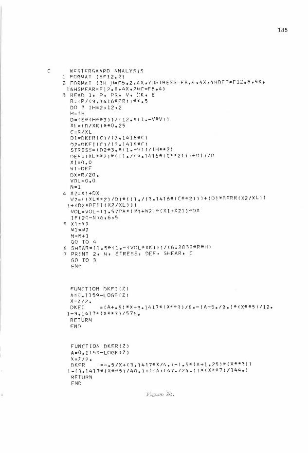
The bending stresses, deflections, and shear stresses plotted in Figures 4 through 9 and 11 through 16 were evaluated using a FORTRAN source program developed from Putnam's equations. The input required by the program includes the design wheel load, the design tire pressure, Young's modulus for the pavement material, Poisson's ratio for the pavement material, and the support modulus. As output, the program lists the bending stress divided by total load, deflection divided by total load, maximum shear stress divided by total load and the ratio of the radius of the loaded area to the radius of relative stiffness of the pavement. These quantities are computed for values of pavement thicknesses ranging from 2 to 12 in. in 2-in. intervals. The input and output formats are consistent with any FORTRAN II processor and can be readily altered for use with any FORTRAN processor. The output format contains Hollerith fields, or H-type alphanumeric data fields, which identify the quantities computed. Figure 17 shows the actual output for a typical analysis.
The reasoning used in the development of the program can be seen in the flow diagram shown in Figure 18.
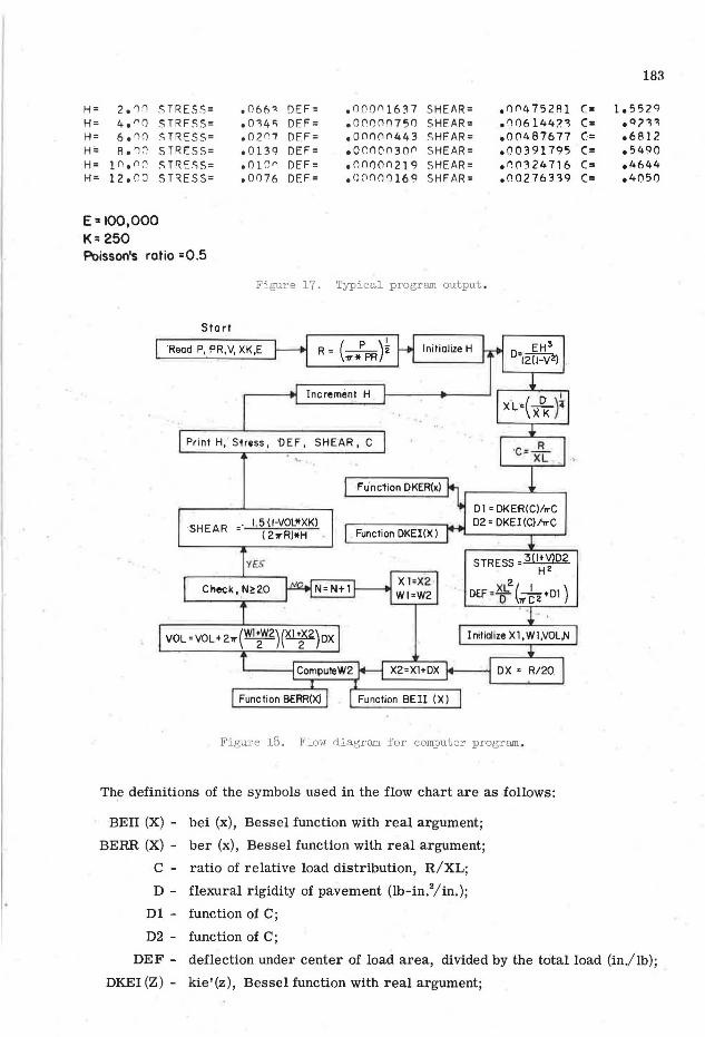
H= 2. '1:1 STRESS= . 0 66<1 DEF= . noon1537 SHE/\R= •1)('4 752Al H= 4. "() STRFSS= • 034<i DEF= .oronrn50 SHEAR= .no6144?."1 H= 6. 0n STRESS= .02 n1 DEF= oonnnn443 SHEAR= 000487677 H'= Ao 'lC' STRESS= 00139 DEF= oor.nornnn SHEAR= 000391795 H= 1 non(' .STRESS= 0 () l '.)" DEF= onnoon219 SHEAR= onn324716 H= 12000 STRESS= .0 0 76 DEF= o0(1()0'll69 SHF/\R= .00276339
E: 100,000 K:;250 Poisson's ra.tio =0.5
Figure 17. T.Y}lical program output .
Sta rt
'Read P, PR,V, XK,E ( p ).!_
R= ~z
Increme·nt H
Print H,' Sires.s, 'DEF, SHEAR, C
FUnc1ion DKER(~)
·SHEAR -1.5 (1-VOL*XK)
(2.,,.R)11H
YES
N=N+1
VOL= VOL+ 2.,,.(~)(~)ox
'------l ComputeW2
Function BERR(X)
Function DKEl()()
X l=X2 · Wl=W2
STRESS= 3 (l+VlD2 HZ
2 DEF •f (k+Dl)
Initialize Xl,Wl,VOL,N
Figure 18. Flow diagram for computer program .
Th~ definitions of the symbols used in the flow chart are as follows:
BEU (X) - bei (x), Bessel function with real argument;
BERR (X) - ber (x), Bessel function with real argument;
C - ratio of relative load distribution, R/XL;
D - flexural rigidity of pavement (lb-in.2/in.);
Dl - function of C;
D2 - function of C;
183
C= l.552q C= • Cl ?'I "I C= 06812 C= 05490 C= 04644 C= 04050
DEF - deflection under center of load area, divided by the total load (in./lb);
DKEI (Z) - kie'(z), Bessel function with real argument;
184
DKER (Z) - ker' (z), Bessel function with real argument;
DX - width of annuli used in calculating reaction under loaded area (in.);
E - Young's modulus for pavement material (psi);
H - pavement thickness {in.);
N - number of annuli used to compute subgrade reaction under loaded area;
P - total load applied at surface (lb);
PR - tire contact pressure for applied load (psi);
R - radius of applied load (in.);
SHEAR - maximum vertical shear stress at edge of applied load divided by total load (psi/lb);
STRESS - maximum bending stress under center of applied load divided by total load {psi/ lb);
V - Poisson's ratio;
VOL - volume of support reaction diagram divided by modulus of subgrade (cu in.);
Wl - deflection at inner radius of annulus (in.);
W2 - deflection at outer radius of annulus (in.);
XK - modulus of support reaction (pci);
XL - radius of relative load distribution;
Xl - inner radius of annulus; and
X2 - outer radius of annulus.
SIART
Initialize BERR,K
Compu1e N,KK. NF ACT
N • N· I
Check (N-1)$0 No
'f•• XNFACT 0 NFACT
NFACT 0 NFACT1tN
Compute SUM,BER
Check [ ABSF(BER-BERR)-00001 $0]
Yes
RETURN
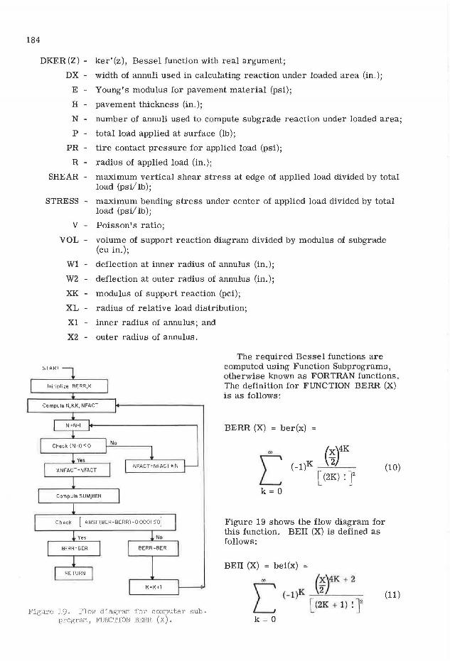
The required Bessel functions are computed using Function Subprograms, otherwise known as FORTRAN functions. The definition for FUNCTION BERR (X) is as follows:
BERR {X) = ber{x)
"' (x)4K ( - l )K ___,_-""""2 __
[ {2K) ! ]2 [ k=O
Figure 19 shows the flow diagram for this function. BEil (X) is defined as follows:
BEil (X) = bei(x) =
"' (~)4K + 2
{10)
(11)
Figure 19. Flow diagram for computer subprogram, FUNCTION BERR (X).
[ k = 0
( - l )K __,_2-'---[ (2K + 1) ! ]2
C WFSTFR~AARD ANALY~iS 1 FORMAT (5Fl2.2l 2 FORMAT (3H H=F5.2,4X,711STRESS=FB.4,4X,4HDFF=Fl2.8,4X, 16HSHEAR=Fl2~8.4X,?HC=FAo4)
3 READ l• p, PR, v, !:K, E R=(P/(3.1416*PRJ l**•5 DO 7 IH=2.I2•2 H=YH D=(E*(H**3l)/(12.*(l.-V*Vll XL=l[)/XKl**0.25 C=R/XL Dl=DKF.R(CJ/13.1416*Cl l)?=nKFY (()/(3.14ln*t) STRESS=([)2*3.*ll.+") l/IH**2l DEF=IXL**2l*( ( l o/("•1416*(C**2l l )+01 l /r'l Xl=O.O '11l=DF.F DX=R/20. VOL=O.O N=l
4 X2=Xl+DX '·'' 2 = ( (XL **2) ID l * ( ( 1 •I (1. 14 l 6* ( C* * 2 l l l + ( D 1 *R FRR IX 2 IXL l 1
l+ID2*REII (X2/Xll)) V 0 L = V 0 L + ( 1 • 5 7 r-Fl * I ~~ l +'I/ 2 ) * ( X 1 + X 2 ) ) *DX IF120-N)6,6•5
c; X l =X? 11Jl ='•I 2 N=N+l GO TO 4
6 SHFAR=(l.5*(1.-(VOL*XK)) )/(6.2832*R*Hl 7 PRINT 2• H• STRESS, DEF• SHEAR• C
GO TO 3 r;:Nn
FUN<T ION DKFI ( 7.) A=v.1159-LOGFIZl X=Z/2. DKEI =(A+.5l*X+3ol417*1X**3l/8.-(A+5./3.J*(X**5l/12•
l-3.1417*(X**7)/576 0
RETURN END
FUNCTION DKFR(Zl A=0.1159-LOGF(Z) X=l/?. DKFR =-.5/X+(3.1417*X/4.)-(.5*(A+l.25l*CX**3))
1- ( 3 • 141 7* ( X ** 5) I 48. ) +I (A+ ( 4 7. 12 4. ) l * ( X ** 7 l I 144 • ) RfTUPM FND
Figure 20.
185
186
FUNCTTON AE!ICX) BEY I=( •"'*Xl**2 K=l
6 N=?*K+1 KK=4*K+2 NFACT=N
3 N=N-1 IFCN-lll'1t2
2 NFACT=NFACT*N GO TO 3
1 XNFACT=NFACT SUM=C<-l.l**Kl*IC.5*Xl**KKl/CXNFACT**2l BfI=REI I+SUM IFCAASF(AEI-REIIl-.0001)4•4•5
5 BEII=BEI K=K+l GO TO 6
4 BEII=BEI RETURN END
FUNCTION r,FRRCX) BERR;:l. K =1
6 N=2*K KK=4*K NFACT=N
3 N =N-1 IFCN-llltl•2
2 NFACT=NFACT*N GO TO 3
1 XNFACT=NFACT SUM=CC-1.l**Kl*I C.<;*Xl~*KKl/CXNFACT**2l BER=AFRR+SUM IF!ABSFCBER-BERRl-.OOOll4t4t5
5 BERR=BER K=K+l GO TO 6
4 BERR=BER RETURN END
* DATA
Figure 20. (Cont'd.)
187
The flow chart for FUNCTION BEii (X) is similar to that of FUNCTION BERR {X) and, therefore, will not be illustrated.
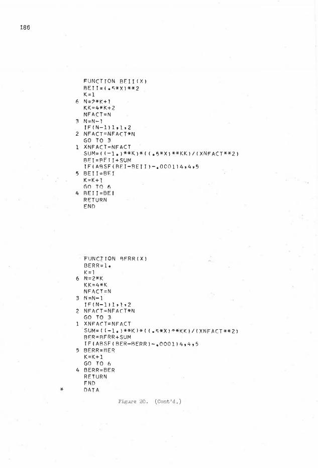
The subprograms used to evaluate DKEI (Z) and DKER (Z) are relatively simple; therefore, they will not be diagramed. These two subprograms are exact for values of the argument less than or equal to one. For values of the argument between 1 and 2, the error is negligible (less than 1 percent), but for values greater than 2 the error increases rapidly. It is for this reason that the quantity C, which is the argument used in this program, is included in the output of the program. An inspection of the program output will reveal the limits of the pavement thickness for which the computed stresses and deflections are exact. For values of E /k <.: 100, the solutions for a 10-kip load with a 70-psi tire pressure are accurate for pavement thicknesses greater than 2 in. Bessel functions available as Library Functions in the software of a particular data processing unit can readily be incorporated into the program and the subprograms can be omitted. The log function, natural log, is the only Library Function required by the program as presented here. Figure 20 shows a complete listing of the main FORTRAN program and the required FORTRAN functions.
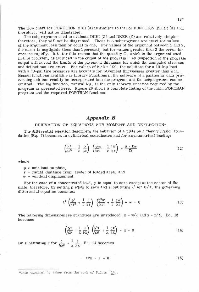
Appendix B DERIVATION OF EQUATIONS FOR MOMENT AND DEFLECTION*
The differential equation describing the behavior of a plate on a "heavy liquid" foundation {Eq. 7) becomes in cylindrical coordinates and for a symmetrical loading:
where
p unit load on plate, r = radial distance from center of loaded area, and
w = vertical displacement.
{12)
For the case of a concentrated load, p is equal to zero except at the center of the plate; therefore, by setting p equal to zero and substituting t
4 for D/k, the governing differential equation becomes:
{13)
The following dimensionless quantities are introduced: z = w/ t and x = r/ t. Eq. 13 becomes
{14)
a 1 a By substituting \J for + - - Eq. 14 becomes ax2 x 0x'
'J'JZ - Z 0 {15)
*This material is taken from the work of Putn81Il (14) .
188
The variable E' xo/T is introduced and Eq. 15 becomes
7'7'z - z 0
0 1 d where the symbol v' stands for - 2 + - - . Eq. 15 is equivalent to o< < o<
v'(V''z +z) - (17'z 1 z) 0
and
71 (v 'z - z) + (17 'z - z) = 0
Thus, it is satisfied by the solution of the Bessel differential equation:
17 I Z + z (l2z 1 (lZ
+ z 0 ~
+ - -€ a<
and
']I Z - z o2z 1 (JZ
0 + - - - z d-=:2 ~ dE"
The combined solution of these two equations can be written as:
where I 0 and K0 are Bessel functions of the first and second kind and of imaginary argument.
(16)
(17)
(18)
(19)
(20)
(21)
The argument x is real and all functions contained in the solution appear in complex form. The real part of the solution is determined by the introduction of four other functions: I 0 (x ± i) = ber x ± bei x, K0 (x ± i) = ker x ± kei x, and setting B1 + B2 = Cit, B1 - B2 = -C2i~,, Ba + B4 = C4t, and Ba - B4 = -Cait, where the constants C1, C2, Ca and C4 are real. The following expression is obtained for the deflection of the plate:
w = C1 ber x + C2 bei x + Ca kei x + C4 ker x (22)
All functions contained in Eq. 22 are real for real values of the argument. The series expressions which are represented by the Kelvin function, for small values of the argument are:
ber x = x•1 xa
1 - 4(16) + 4(16) {36) (64) ... '
bei x = x2 xe 4 - (4) (16) {36)'
ker x = (ln 2 - j - ln x) + ;~ - :~ (1n 2 - j - ln x + ~) ... , and
kei x = -rr . x2 x 4
4 + (ln 2 - J - ln x + 1) 4 + 256 ,
189
in which j is 0. 57722, Euler's constant; and ln 2 - j = 0. 11593. The values of the Kelvin functions and their first derivatives are available in tabulated form for the pertinent values of the argument (19).
The general solution can be used for the analysis of any problem of symmetrical bending of a circular plate resting on a dense liquid foundation. The four constants must be determined for each particular case. For the case of loading under consideration (a concentrated load, P, applied at a point, x = 0, of an infinitely extended plate), the deflection of the plate at some distance, x, must be equal to zero. The functions ber x and bei x increase indefinitely with increasing values of x; therefore, the constants C1 and C2 must assume a value of zero to satisfy the boundary condition. The value of ker x becomes infinitely large at the origin, x = 0.
By setting C1 = C 2 = C 4 = 0, the deflection equation (Eq. 22) reduces to
w = C 3 kei x (23)
The constant, C3, is evaluated by considering the shearing forces. The shearing force, per unit length, is written as:
By substituting the first terms of the series expression for kei x in Eq. 23 and taking the derivative, the following expression is obtained:
C3D d ( 7TX2 ) --3- dx -lnx + 16' .. (25a)
-C3D (1 7TX ) Qr = ---:t3 x + a· .. (25b)
Q C3D 1 As the value of x decreases, the value of r approaches -V :x·
(26)
The shearing force may also be obtained by distributing the load, P, uniformly over a circumference of radius, r:
Setting Eq. 23 equal to Eq. 27 yields :
and
w
p - 27Tr
Pt2 • --- ke1 x
27TD
(27)
(28)
(29)
190
The value of D can be substituted into Eq. 29 to obtain:
w p k. - 2?Tkt2 e1 x (30)
To obtain the deflection at the center of a uniform circular load, consider an element of the loaded area:
dA = rd 9 dr (31)
and the increment of load on the element of area:
dP pdA = 7T~2 r dr d9 (32)
The increment of deflection which is caused at the origin (r = 0) by the load on the element of area is a function of the distance of the load from the origin (r) and is dependent on the direction of the load from the origin (9). Therefore, by use of the influence function for the concentrated load, Eq. 29, the increment of deflection at the origin caused by the load, dP, at a distance, r, is:
. P . . I t2 , - ' aw0 - - 7Ta2 r ar O!:i ~2 7TD Ke1 J (33)
Because Eq. 33 represents the increment of deflection caused at the center of the loaded area by the load on each element of the area, the total deflection at the origin will be the summation of the increments of deflection:
r = a 9 = 27T
Pt2
[ [ -71
a2 (271
D) r dr kei x (34)
r = O 9 = 0
In the limit Eq. 34 becomes the integral expression for deflection under the center of a distributed load; thus
Pt2 a 2'11
Jo Jo r dr de kei x (35)
By integrating between the limits, 9 = 0 and 9 = 21T, and substituting x = r/ t, Eq. 35 becomes:
J: r kei (~) dr (36)
A solution to Eq. 36 is written as
191
p.i,2 [ , (r)]a Wo = 11Da2 rt ker t 0 (37)
For a value of r = 0, the expression in the brackets of Eq. 37 takes a value of -t2;
therefore, by substitution of the limits, r = 0 and r = a, Eq. 37 may be written:
w0 = 11~~~ [ t 2 + atker' (~)] (38a)
or
(38b)
and by substituting the dimensionless parameter, c = a/ l (the radius of relative load distribution):
wo Pt2 [_!_ + .! ker' c] TTD c2 c
(39a)
or
Pt2 [ J w0 = rrDcz 1 + c ker' c (39b)
The increment of moment which is produced at the origin by the load on an element of area is a function of the distance from the origin, r, and the direction, 9. However, for the special case of symmetrical loading, represented by the circular area of load distribution, the moment which is produced at the origin may be obtained by integration over the surface of loading by considering the equation of deflection for a concentrated load and the equations of bending for a symmetrically loaded plate:
( d2w " dw) mr = -D - + t= -dr2 r dr
(40)
and
(1 dw d
2w) mt= -D - - + µ-r dr dr2 (41)
The radial and tangential bending moments are equal at the origin for a symmetrical loading condition, therefore,
m _ = mr + mt = -D (.!...±..1!) (d2w + .! dw)
r - 0 2 2 dr2 r dr (42)
By considering Eq. 30 for deflection of a concentrated load, and the derivatives:
dw Pt2
dr = - 2rrD kei' f (43a)
and
192
and by adding:
Pt2 k . ,, r --- e1 -27TD t
d2w + _! dw = - Pt2 (kei" £ + _! kei' £) dr2 r dr 277 D t r t
and by substituting the identity relationship:
we may obtain
k .,,r lk.,r el t + r el t 1 r
t 2 ker t
d2w 1 dw P r dr2 + r dr = - 27T D ker t
(43b)
(44)
Thus, the increment of total bending moment produced at the origin by the load on an element of the loaded area is given by:
11 ... ,.) p 1 dm = ~ -=-
2-77
r ctr cte ker 2 .,,.a2 (45)
and, at the limit, the total bending moment produced at the origin by loading over the circular area is:
a _ (1 + µ)P i (£) m - ~1T a•
0 r ker t ctr (46)
and integration of Eq. 46 between the limits of r = 0 and r = a yields:
mmax P(l + µ) [at kei' (~) J 21Ta2 '-'
(47a)
or
P(l + µ) [ 1 k . I J mmax = 27T c e1 c. (47b)
Eq. 47b for the maximum moment and Eq. 39b for the deflection under the center of the loads are the equations used in the computer program to compute STRESS and DEF, respectively.