Embed Size (px)
Citation preview
Lonsdale Design Guide
Introduction This Design Guide has been produced to assist specifiers and designers by illustrating typical installation details for sloped and vertical patent glazing. It is not exhaustive, but it does illustrate good practice for most applications and all details are in accordance with BS5516 for the design and installation of sloped and vertical patent glazing. Users of this guide must exercise all reasonable care to ensure that the details and products of Lonsdale Metal Company Limited are suitable for the intended purpose. If in doubt, ask us. Having decided to specify Lonsdale Patent Glazing, to save you valuable drafting time, CAD drawings of typical installation details are available on disk or from our website : www.roofglazing.co.uk If you require assistance please contact our Technical Department. Lonsdale Metal Company Limited, Millmead Industrial Centre, Mill Mead Road, London. N17 9QU Telephone : 020 8801 4221 Facsimile: 020 8801 1287 Contents
Page Ranges
Page Introduction
1
Guide to Selection of Glazing Bars
2
Cleaning and Maintenance
3
Recommended further reading
3
Maximum span between supports
4 & 5
Technical Summary
6 & 7
Typical Specifications
8 & 9
Drawings & CAD Code Index
10 to 13
SkyGard
14 to 32
PlasGard
33 to 50
ThermGard Including conservatory rafter glazing bars
51 to 90
SpanGard
91 to 97
GlazaTherm
98 to 103
Research & Development
104
www.roofglazing.co.uk Page 1
PRINT OUT THIS DESIGN GUIDE FOR REFERENCE IF YOU WISH. CLICK THE Pages TAB TO SEE THUMBNAILS OF ALL THE PAGES IN THE PUBLICATION.
TO PRINT OUT INDIVIDUAL PAGES, CLICK File, Print THEN CHECK Current page OR SELECT Pages RANGE AND CLICK OK. TO PRINT DRAWINGS TO THE SCALE INDICATED YOUR PRINT DRIVER MUST BE CAPABLE OF BEING SET AT 100%. LOOK IN YOUR PRINTER’S
Properties FOR SETTINGS. CONTACT OUR TECHNICAL DEPARTMENT FOR FURTHER ADVICE.
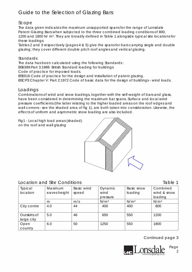
Guide to the Selection of Glazing Bars Scope The data given indicates the maximum unsupported spans for the range of Lonsdale Patent Glazing Bars when subjected to the three combined loading conditions of 800, 1200 and 1800 N/ m². They are broadly defined in Table 1 alongside typical site locations for these loadings. Tables 2 and 3 respectively (pages 4 & 5) give the spans for bars carrying single and double glazing; they cover different double pitch roof angles and vertical glazing. Standards The data has been calculated using the following Standards : BS6399:Part 3:1988 British Standard loading for buildings Code of practice for imposed loads. BS5516 Code of practice for the design and installation of patent glazing. BSCP3:Chapter V: Part 2:1972 Code of basic data for the design of buildings - wind loads. Loadings Combinations of wind and snow loadings, together with the self-weight of bars and glass, have been considered in determining the maximum bar spans. Surface and local wind pressure coefficients (the latter relating to the higher loaded areas on the roof edges and wall comers - see the shaded area of fig 1), are both taken into consideration. Likewise, the effects of uniform and asymmetric snow loading are also included. Fig1 - Local high load areas (shaded) on the roof and wall glazing Location and Site Conditions Table 1
Maximum eaves height
Basic wind speed
Dynamic wind pressure
Basic snow loading
Combined wind & snow loading
Typical location
m m/s N/m² N/m² N/m² City centre
4.0 44 400 400 800
Outskirts of large city
5.0 46 650 550 1200
Open country
6.0 50 1250 550 1800
Continued page 3
Page 2
Guide to the Selection of Glazing Bars - continued Limitations Tables 2 and 3 (pages 4 & 5) are restricted to :
• Glazed walls and double pitched roofs of rectangular clad buildings of height / width ratios up to 6 : 1 and length / width ratios up to 4 :1.
• Two edge support of glass on bars spaced at 600mm. • Single glazing using 6mm polished or 7mm wired cast glass. • Hermetically sealed double glazed units, with 6mm thick float, toughened or
laminated glass in any combination. Failure Conditions The glazing bar spans given will not fail due to either excessive deflection or stressing of the components, in accordance with the above standards. Technical Support Care should be taken in applying the above data to different site locations, conditions, building size or roof types (including canopies ). In such instances, Lonsdale Metal Company will be pleased to give further advice, upon request. Cleaning and Maintenance Recommended procedures can be found on our website www.roofglazing.co.uk and in BS5516 - Code of practice for the design & installation of sloping and vertical patent glazing. In addition, if materials are coated with an architectural finish e.g. polyester powder paint, advice should be sought from the manufacturers / applicator of the process. Recommended further reading BS5516 - Code of practice for the design & installation of sloping and vertical patent glazing BS6399:Part 3 - Loading for buildings - Code of practice for imposed loads BS CP3 Chapter V Part 2 - Code of basic data for the design of buildings - Wind loads NBS Specification H10 Patent Glazing
Continued on page 4
Page 3
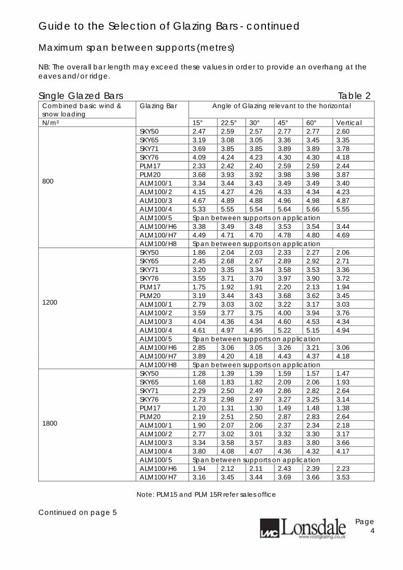
Guide to the Selection of Glazing Bars - continued Maximum span between supports (metres) NB: The overall bar length may exceed these values in order to provide an overhang at the eaves and/or ridge. Single Glazed Bars Table 2
Combined basic wind & snow loading
Angle of Glazing relevant to the horizontal
N/m²
Glazing Bar
15° 22.5° 30° 45° 60° Vertical SKY50 2.47 2.59 2.57 2.77 2.77 2.60 SKY65 3.19 3.08 3.05 3.36 3.45 3.35 SKY71 3.69 3.85 3.85 3.89 3.89 3.78 SKY76 4.09 4.24 4.23 4.30 4.30 4.18 PLM17 2.33 2.42 2.40 2.59 2.59 2.44 PLM20 3.68 3.93 3.92 3.98 3.98 3.87 ALM100/1 3.34 3.44 3.43 3.49 3.49 3.40 ALM100/2 4.15 4.27 4.26 4.33 4.34 4.23 ALM100/3 4.67 4.89 4.88 4.96 4.98 4.87 ALM100/4 5.33 5.55 5.54 5.64 5.66 5.55 ALM100/5 Span between supports on application ALM100/H6 3.38 3.49 3.48 3.53 3.54 3.44 ALM100/H7 4.49 4.71 4.70 4.78 4.80 4.69
800
ALM100/H8 Span between supports on application SKY50 1.86 2.04 2.03 2.33 2.27 2.06 SKY65 2.45 2.68 2.67 2.89 2.92 2.71 SKY71 3.20 3.35 3.34 3.58 3.53 3.36 SKY76 3.55 3.71 3.70 3.97 3.90 3.72 PLM17 1.75 1.92 1.91 2.20 2.13 1.94 PLM20 3.19 3.44 3.43 3.68 3.62 3.45 ALM100/1 2.79 3.03 3.02 3.22 3.17 3.03 ALM100/2 3.59 3.77 3.75 4.00 3.94 3.76 ALM100/3 4.04 4.36 4.34 4.60 4.53 4.34 ALM100/4 4.61 4.97 4.95 5.22 5.15 4.94 ALM100/5 Span between supports on application ALM100/H6 2.85 3.06 3.05 3.26 3.21 3.06 ALM100/H7 3.89 4.20 4.18 4.43 4.37 4.18
1200
ALM100/H8 Span between supports on application SKY50 1.28 1.39 1.39 1.59 1.57 1.47 SKY65 1.68 1.83 1.82 2.09 2.06 1.93 SKY71 2.29 2.50 2.49 2.86 2.82 2.64 SKY76 2.73 2.98 2.97 3.27 3.25 3.14 PLM17 1.20 1.31 1.30 1.49 1.48 1.38 PLM20 2.19 2.51 2.50 2.87 2.83 2.64 ALM100/1 1.90 2.07 2.06 2.37 2.34 2.18 ALM100/2 2.77 3.02 3.01 3.32 3.30 3.17 ALM100/3 3.34 3.58 3.57 3.83 3.80 3.66 ALM100/4 3.80 4.08 4.07 4.36 4.32 4.17 ALM100/5 Span between supports on application ALM100/H6 1.94 2.12 2.11 2.43 2.39 2.23
1800
ALM100/H7 3.16 3.45 3.44 3.69 3.66 3.53
Note: PLM15 and PLM 15R refer sales office Continued on page 5
Page 4
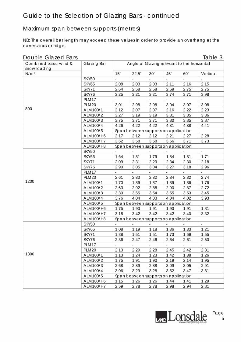
Guide to the Selection of Glazing Bars - continued Maximum span between supports (metres) NB: The overall bar length may exceed these values in order to provide an overhang at the eaves and/or ridge. Double Glazed Bars Table 3
Combined basic wind & snow loading
Angle of Glazing relevant to the horizontal
N/m²
Glazing Bar
15° 22.5° 30° 45° 60° Vertical SKY50 - - - - - - SKY65 2.08 2.03 2.03 2.11 2.16 2.15 SKY71 2.64 2.58 2.58 2.69 2.75 2.75 SKY76 3.25 3.21 3.21 3.74 3.71 3.98 PLM17 - - - - - - PLM20 3.01 2.98 2.98 3.04 3.07 3.08 ALM100/1 2.12 2.07 2.07 2.16 2.22 2.23 ALM100/2 3.27 3.19 3.19 3.31 3.35 3.36 ALM100/3 3.75 3.71 3.71 3.80 3.85 3.87 ALM100/4 4.26 4.22 4.22 4.31 4.38 4.41 ALM100/5 Span between supports on application ALM100/H6 2.17 2.12 2.12 2.21 2.27 2.28 ALM100/H7 3.62 3.58 3.58 3.66 3.71 3.73
800
ALM100/H8 Span between supports on application SKY50 - - - - - - SKY65 1.64 1.81 1.79 1.84 1.81 1.71 SKY71 2.09 2.31 2.29 2.34 2.30 2.18 SKY76 2.90 3.05 3.04 3.27 3.18 2.96 PLM17 - - - - - - PLM20 2.61 2.83 2.82 2.84 2.82 2.74 ALM100/1 1.70 1.89 1.87 1.89 1.86 1.76 ALM100/2 2.63 2.92 2.88 2.90 2.87 2.72 ALM100/3 3.30 3.55 3.54 3.55 3.53 3.45 ALM100/4 3.76 4.04 4.03 4.04 4.02 3.93 ALM100/5 Span between supports on application ALM100/H6 1.75 1.93 1.91 1.93 1.91 1.81 ALM100/H7 3.18 3.42 3.42 3.42 3.40 3.32
1200
ALM100/H8 Span between supports on application SKY50 - - - - - - SKY65 1.08 1.19 1.18 1.36 1.33 1.21 SKY71 1.38 1.51 1.51 1.73 1.69 1.55 SKY76 2.36 2.47 2.46 2.64 2.61 2.50 PLM17 - - - - - - PLM20 2.13 2.29 2.28 2.45 2.42 2.31 ALM100/1 1.13 1.24 1.23 1.42 1.38 1.26 ALM100/2 1.75 1.91 1.90 2.19 2.14 1.95 ALM100/3 2.68 2.89 2.88 3.09 3.05 2.91 ALM100/4 3.06 3.29 3.28 3.52 3.47 3.31 ALM100/5 Span between supports on application ALM100/H6 1.15 1.26 1.26 1.44 1.41 1.29
1800
ALM100/H7 2.59 2.78 2.78 2.98 2.94 2.81
Page 5
Technical Summary Patent Glazing Bars Specification Glazing Bars, Cappings, Beads and Fittings are extruded aluminium alloy 6063-T6 to BS1474. Fasteners provided are either stainless steel to BS304515 Grade A2 or mild steel bright zinc plated. Gaskets are extruded Thermo Plastic Rubber quality 98625 to BS4255:Part1:1986 Grade C. Performance All systems are designed to conform with the requirements of BS5516 when installed within the manufacturers recommendations. A guide to maximum spans is given on pages 4 & 5 of the Design Guide and should be referred to prior to planning an installation. Fixing Fixing to timber is directly through the channels at the top of the glazing bars with two No. 10 x 1.5 inch bright zinc plated wood screws and a sliding shoe with wood screws at the bottom end. Fixing to metal is with M8 Single Hole Fixing Shoes positively fixed at the top and sliding at the bottom end. Dissimilar metals should be isolated to avoid bi-metallic corrosion Appearance Materials are supplied Mill Finished as standard. A range of architectural finishes is available including polyester powder coating to BS6496 in standard RAL or BS colour ranges. Ventilation May be achieved either through GlazaTherm, our top hung roof ventilator, or by casement vents in vertical applications. Various factory fitted opening mechanisms are available including manual, pole or cord operated, electrical, thermostatic or smoke activated controls. Infill All popular specifications can be accommodated including 6 / 7mm Single Glazing, 24mm and 28mm Double Glazed Sealed Units or 10mm,16mm or 25mm Polycarbonate Sheeting. Other infills should be discussed with our technical department. Double Glazed combinations should feature a suitable "step" to the bottom edge to avoid thermal breaking. Building Regulations Please visit our website www.roofglazing.co.uk for guidance and compliance with the Regulations relating to fire, non-fragility, thermal and air-tightness performance.
Continued page 7
Page 6
Technical Summary - continued SpanGard - Self supporting roof-lights Geometry and Dimensions Pyramids, rectangles, hexagons, octagons and polygons are all possible within the boundaries of regular geometry. Standard roof pitches are from 22.5° in 5° increments to 45°. Roof lights may be manufactured to infinite length with a width restriction up to 6000mm subject to infill and roof pitch.. Vertical up-stands on Lantern lights are approximately 500mm high as standard, but other heights may be incorporated on request. Special commissions for irregular shapes, sizes and pitches should be discussed with our technical department. Specification Fabricated from the ThermGard series patent glazing system incorporating extruded aluminium alloy 6063-T6 Ridge, Hip, Eaves, Cill, and Flashings to BS1474. Supplied in component form for assembling on site to form entirely self-supporting structure. All joints are TIG welded or mechanically jointed with spigots and stainless steel fasteners to BS304515. Gaskets are extruded Thermoplastic Rubber quality 98625 to BS4255:Part 1 Grade C. Performance SpanGard is designed to conform with the requirements of BS5 516 when installed within manufacturers recommendations. Thermal Break If required a thermally improved option is available. Please contact our technical department for further details. Appearance Materials are supplied Mill Finish as standard. A range of architectural finishes is available including polyester powder coating to BS6496 in standard RAL or BS colour ranges. Ventilation May be achieved either through GlazaTherm, our top hung roof ventilator, or by casement vents in the up-stands of Lantern lights. Various factory fitted opening mechanisms are available including manual, pole or cord operated, electrical, thermostatic or smoke activated controls. Infill All popular specifications can be accommodated including 6 / 7mm Single Glazing, 24mm or 28mm Double Glazed Sealed Units or 10mm, 16mm or 25mm Polycarbonate Sheeting. Other infills should be discussed with our technical department. Double Glazed combinations should feature a suitable "step" to the bottom edge to avoid thermal breaking. Fixing Must be carried out using a suitable fastner to a structural curb capable of withstanding the relevant imposed self-weight, wind and snow loads without spread or movement Building Regulations relating to SpanGard Please visit our website www.roofglazing.co.uk for guidance and compliance with the Regulations relating to fire, non-fragility, thermal and air-tightness performance.
Page 7
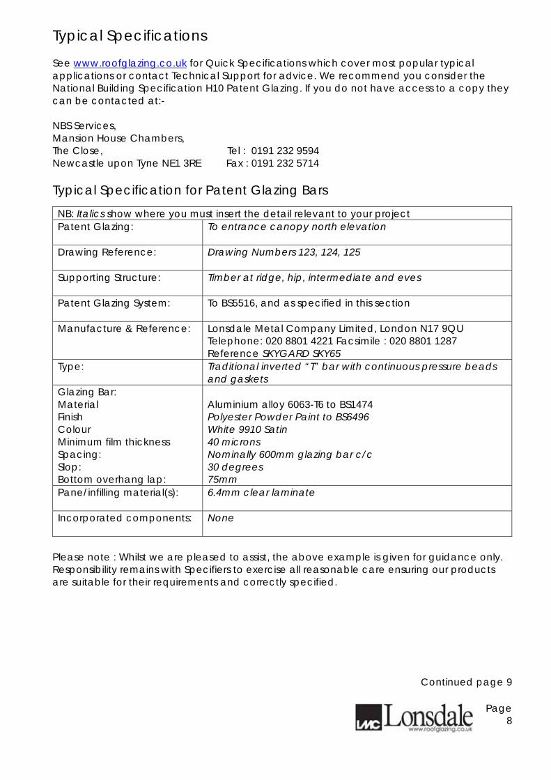
Typical Specifications See www.roofglazing.co.uk for Quick Specifications which cover most popular typical applications or contact Technical Support for advice. We recommend you consider the National Building Specification H10 Patent Glazing. If you do not have access to a copy they can be contacted at:- NBS Services, Mansion House Chambers, The Close, Tel : 0191 232 9594 Newcastle upon Tyne NE1 3RE Fax : 0191 232 5714 Typical Specification for Patent Glazing Bars NB: Italics show where you must insert the detail relevant to your project Patent Glazing:
To entrance canopy north elevation
Drawing Reference:
Drawing Numbers 123, 124, 125
Supporting Structure:
Timber at ridge, hip, intermediate and eves
Patent Glazing System:
To BS5516, and as specified in this section
Manufacture & Reference: Lonsdale Metal Company Limited, London N17 9QU Telephone: 020 8801 4221 Facsimile : 020 8801 1287 Reference SKYGARD SKY65
Type: Traditional inverted “T” bar with continuous pressure beads and gaskets
Glazing Bar: Material Finish Colour Minimum film thickness Spacing: Slop: Bottom overhang lap:
Aluminium alloy 6063-T6 to BS1474 Polyester Powder Paint to BS6496 White 9910 Satin 40 microns Nominally 600mm glazing bar c/c 30 degrees 75mm
Pane/infilling material(s):
6.4mm clear laminate
Incorporated components:
None Please note : Whilst we are pleased to assist, the above example is given for guidance only. Responsibility remains with Specifiers to exercise all reasonable care ensuring our products are suitable for their requirements and correctly specified.
Continued page 9
Page 8
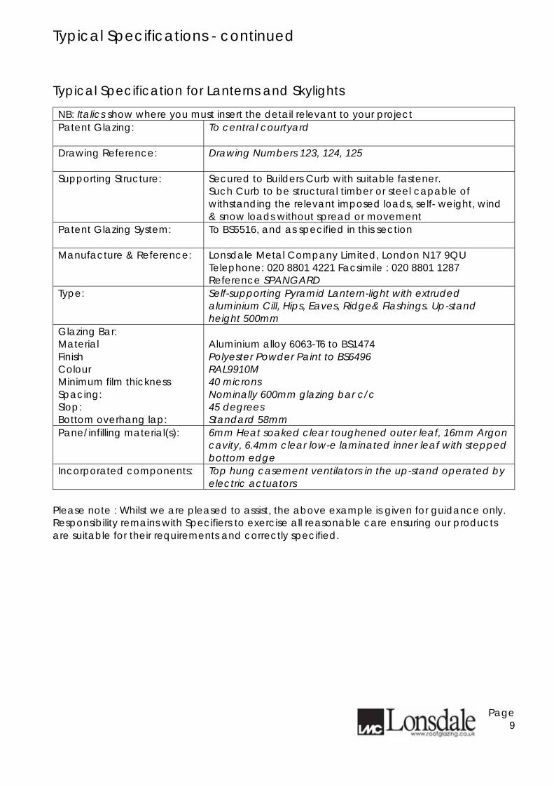
Typical Specifications - continued Typical Specification for Lanterns and Skylights NB: Italics show where you must insert the detail relevant to your project Patent Glazing:
To central courtyard
Drawing Reference:
Drawing Numbers 123, 124, 125
Supporting Structure:
Secured to Builders Curb with suitable fastener. Such Curb to be structural timber or steel capable of withstanding the relevant imposed loads, self- weight, wind & snow loads without spread or movement
Patent Glazing System:
To BS5516, and as specified in this section
Manufacture & Reference: Lonsdale Metal Company Limited, London N17 9QU Telephone: 020 8801 4221 Facsimile : 020 8801 1287 Reference SPANGARD
Type: Self-supporting Pyramid Lantern-light with extruded aluminium Cill, Hips, Eaves, Ridge& Flashings. Up-stand height 500mm
Glazing Bar: Material Finish Colour Minimum film thickness Spacing: Slop: Bottom overhang lap:
Aluminium alloy 6063-T6 to BS1474 Polyester Powder Paint to BS6496 RAL9910M 40 microns Nominally 600mm glazing bar c/c 45 degrees Standard 58mm
Pane/infilling material(s): 6mm Heat soaked clear toughened outer leaf, 16mm Argon cavity, 6.4mm clear low-e laminated inner leaf with stepped bottom edge
Incorporated components: Top hung casement ventilators in the up-stand operated by electric actuators
Please note : Whilst we are pleased to assist, the above example is given for guidance only. Responsibility remains with Specifiers to exercise all reasonable care ensuring our products are suitable for their requirements and correctly specified.
Page 9
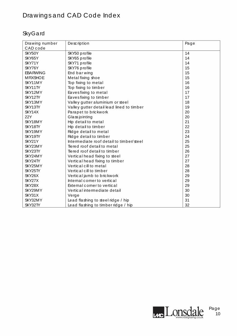
Drawings and CAD Code Index SkyGard
Drawing number CAD code
Description Page
SKY50Y SKY65Y SKY71Y SKY76Y EBARWING MFIXSHOE SKY11MY SKY11TY SKY12MY SKY12TY SKY13MY SKY13TY SKY14X 22Y SKY18MY SKY18TY SKY19MY SKY19TY SKY21Y SKY23MY SKY23TY SKY24MY SKY24TY SKY25MY SKY25TY SKY26X SKY27X SKY28X SKY29MY SKY31X SKY32MY SKY32TY
SKY50 profile SKY65 profile SKY71 profile SKY76 profile End bar wing Metal fixing shoe Top fixing to metal Top fixing to timber Eaves fixing to metal Eaves fixing to timber Valley gutter aluminium or steel Valley gutter detail lead lined to timber Parapet to brickwork Glass jointing Hip detail to metal Hip detail to timber Ridge detail to metal Ridge detail to timber Intermediate roof detail to timber/steel Tiered roof detail to metal Tiered roof detail to timber Vertical head fixing to steel Vertical head fixing to timber Vertical cill to metal Vertical cill to timber Vertical jamb to brickwork Internal corner to vertical External corner to vertical Vertical intermediate detail Verge Lead flashing to steel ridge / hip Lead flashing to timber ridge / hip
14 14 14 15 15 15 16 16 17 17 18 19 20 20 21 22 23 24 25 25 26 27 27 28 28 29 29 29 30 30 31 32
Page 10
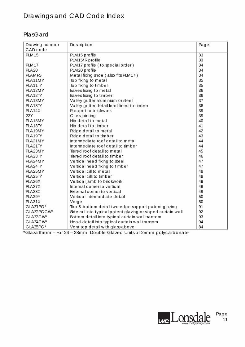
Drawings and CAD Code Index PlasGard
Drawing number CAD code
Description Page
PLM15 PLM17 PLA20 PLAMFS PLA11MY PLA11TY PLA12MY PLA12TY PLA13MY PLA13TY PLA14X 22Y PLA18MY PLA18TY PLA19MY PLA19TY PLA21MY PLA21TY PLA23MY PLA23TY PLA24MY PLA24TY PLA25MY PLA25TY PLA26X PLA27X PLA28X PLA29Y PLA31X GLAZ1PG* GLAZ2PGCW* GLAZ3CW* GLAZ4CW* GLAZ5PG*
PLM15 profile PLM15/R profile PLM17 profile ( to special order ) PLM20 profile Metal fixing shoe ( also fits PLM17 ) Top fixing to metal Top fixing to timber Eaves fixing to metal Eaves fixing to timber Valley gutter aluminium or steel Valley gutter detail lead lined to timber Parapet to brickwork Glass jointing Hip detail to metal Hip detail to timber Ridge detail to metal Ridge detail to timber Intermediate roof detail to metal Intermediate roof detail to timber Tiered roof detail to metal Tiered roof detail to timber Vertical head fixing to steel Vertical head fixing to timber Vertical cill to metal Vertical cilll to timber Vertical jamb to brickwork Internal corner to vertical External corner to vertical Vertical intermediate detail Verge Top & bottom detail two edge support patent glazing Side rail into typical patent glazing or sloped curtain wall Bottom detail into typical curtain wall transom Head detail into typical curtain wall transom Vent top detail with glass above
33 33 34 34 34 35 35 36 36 37 38 39 39 40 41 42 43 44 44 45 46 47 47 48 48 49 49 49 50 50 91 92 93 94 84
*GlazaTherm – For 24 – 28mm Double Glazed Units or 25mm polycarbonate
Page 11
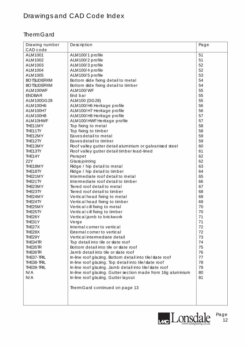
Drawings and CAD Code Index ThermGard
Drawing number CAD code
Description Page
ALM1001 ALM1002 ALM1003 ALM1004 ALM1005 BOTSLIDEFIXM BOTSLIDEFIXM ALM100WF ENDBAR ALM100DG28 ALM100H6 ALM100H7 ALM100H8 ALM10HWF THE11MY THE11TY THE12MY THE12TY THE13MY THE13TY THE14Y 22Y THE18MY THE18TY THE21MY THE21TY THE23MY THE23TY THE24MY THE24TY THE25MY THE25TY THE26Y THE31Y THE27X THE28X THE29Y THE34TR THE35TR THE36TR THE37-TRIL THE38-TRIL THE39-TRIL N/A N/A
ALM100/1 profile ALM100/2 profile ALM100/3 profile ALM100/4 profile ALM100/5 profile Bottom slide fixing detail to metal Bottom slide fixing detail to timber ALM100/WF End bar ALM100 (DG28) ALM100/H6 Heritage profile ALM100/H7 Heritage profile ALM100/H8 Heritage profile ALM100/HWF Heritage profile Top fixing to metal Top fixing to timber Eaves detail to metal Eaves detail to timber Roof valley gutter detail aluminium or galvanised steel Roof valley gutter detail timber lead-lined Parapet Glass jointing Ridge / hip detail to metal Ridge / hip detail to timber Intermediate roof detail to metal Intermediate roof detail to timber Tiered roof detail to metal Tiered roof detail to timber Vertical head fixing to metal Vertical head fixing to timber Vertical cill fixing to metal Vertical cill fixing to timber Vertical jamb to brickwork Verge Internal corner to vertical External corner to vertical Vertical intermediate detail Top detail into tile or slate roof Bottom detail into tile or slate roof Jamb detail into tile or slate roof In-line roof glazing. Bottom detail into tile/slate roof In-line roof glazing. Top detail into tile/slate roof In-line roof glazing. Jamb detail into tile/slate roof In-line roof glazing. Gutter section made from 16g aluminium In-line roof glazing. Gutter layout ThermGard continued on page 13
51 51 52 52 53 54 54 55 55 55 56 56 57 57 58 58 59 59 60 61 62 62 63 64 65 66 67 68 69 69 70 70 71 71 72 72 73 74 75 76 77 78 79 80 81
Page 12
Drawings and CAD Code Index
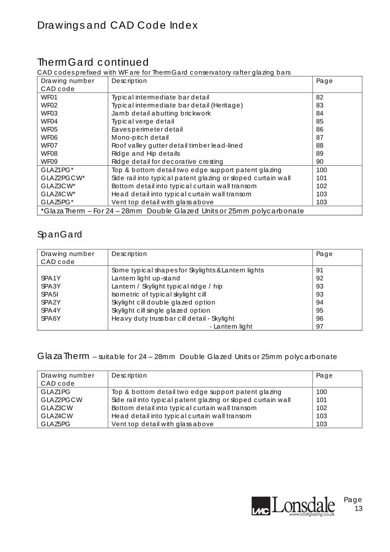
ThermGard continued CAD codes prefixed with WF are for ThermGard conservatory rafter glazing bars
Drawing number CAD code
Description Page
WF01 WF02 WF03 WF04 WF05 WF06 WF07 WF08 WF09
Typical intermediate bar detail Typical intermediate bar detail (Heritage) Jamb detail abutting brickwork Typical verge detail Eaves perimeter detail Mono-pitch detail Roof valley gutter detail timber lead-lined Ridge and Hip details Ridge detail for decorative cresting
82 83 84 85 86 87 88 89 90
GLAZ1PG* GLAZ2PGCW* GLAZ3CW* GLAZ4CW* GLAZ5PG*
Top & bottom detail two edge support patent glazing Side rail into typical patent glazing or sloped curtain wall Bottom detail into typical curtain wall transom Head detail into typical curtain wall transom Vent top detail with glass above
100 101 102 103 103
*GlazaTherm – For 24 – 28mm Double Glazed Units or 25mm polycarbonate SpanGard
Drawing number CAD code
Description Page
SPA1Y SPA3Y SPA5I SPA2Y SPA4Y SPA6Y
Some typical shapes for Skylights &Lantern lights Lantern light up-stand Lantern / Skylight typical ridge / hip Isometric of typical skylight cill Skylight cill double glazed option Skylight cill single glazed option Heavy duty truss bar cill detail - Skylight - Lantern light
91 92 93 93 94 95 96 97
GlazaTherm – suitable for 24 – 28mm Double Glazed Units or 25mm polycarbonate
Drawing number CAD code
Description Page
GLAZ1PG GLAZ2PGCW GLAZ3CW GLAZ4CW GLAZ5PG
Top & bottom detail two edge support patent glazing Side rail into typical patent glazing or sloped curtain wall Bottom detail into typical curtain wall transom Head detail into typical curtain wall transom Vent top detail with glass above
100 101 102 103 103
Page 13
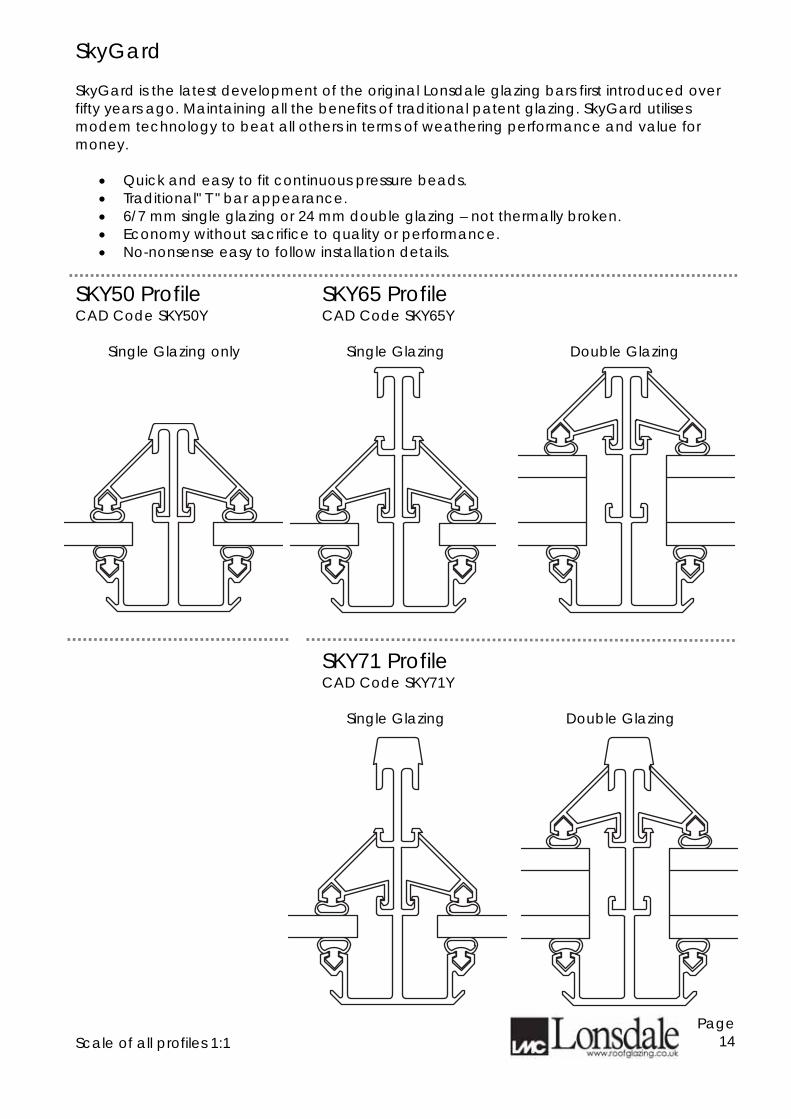
SkyGard SkyGard is the latest development of the original Lonsdale glazing bars first introduced over fifty years ago. Maintaining all the benefits of traditional patent glazing. SkyGard utilises modem technology to beat all others in terms of weathering performance and value for money.
• Quick and easy to fit continuous pressure beads. • Traditional" T " bar appearance. • 6/7 mm single glazing or 24 mm double glazing – not thermally broken. • Economy without sacrifice to quality or performance. • No-nonsense easy to follow installation details.
SKY50 Profile CAD Code SKY50Y
SKY65 Profile CAD Code SKY65Y
Single Glazing only
Single Glazing Double Glazing
SKY71 Profile CAD Code SKY71Y
Single Glazing
Double Glazing
Scale of all profiles 1:1
Page 14
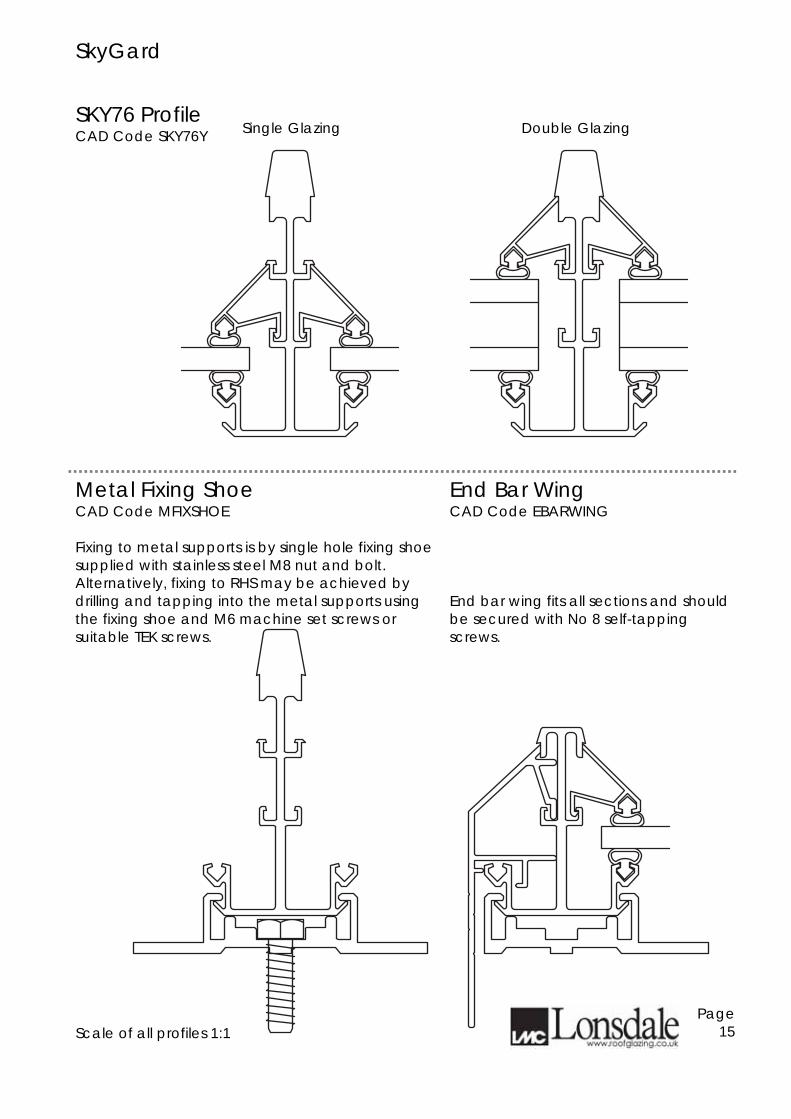
SkyGard SKY76 Profile CAD Code SKY76Y
Single Glazing
Double Glazing
Metal Fixing Shoe CAD Code MFIXSHOE
End Bar Wing CAD Code EBARWING
Fixing to metal supports is by single hole fixing shoe supplied with stainless steel M8 nut and bolt. Alternatively, fixing to RHS may be achieved by drilling and tapping into the metal supports using the fixing shoe and M6 machine set screws or suitable TEK screws.
End bar wing fits all sections and should be secured with No 8 self-tapping screws.
Scale of all profiles 1:1
Page 15
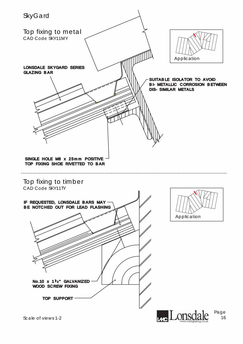
SkyGard Top fixing to metal CAD Code SKY11MY
Top fixing to timber CAD Code SKY11TY
Scale of views 1-2
Page 16
DIS-SIMILAR METALSDIS-SIMILAR METALS
BI-METALLIC CORROSION BETWEENBI-METALLIC CORROSION BETWEEN
SUITABLE ISOLATOR TO AVOIDSUITABLE ISOLATOR TO AVOID
SINGLE HOLE M8 x 25mm POSITIVESINGLE HOLE M8 x 25mm POSITIVE
TOP FIXING SHOE RIVETTED TO BARTOP FIXING SHOE RIVETTED TO BAR
LONSDALE SKYGARD SERIESLONSDALE SKYGARD SERIES
GLAZING BARGLAZING BAR
No.10 x 1 " GALVANIZEDNo.10 x 1 " GALVANIZED
TOP SUPPORTTOP SUPPORT
WOOD SCREW FIXINGWOOD SCREW FIXING
//11 22
BE NOTCHED OUT FOR LEAD FLASHINGBE NOTCHED OUT FOR LEAD FLASHING
IF REQUESTED, LONSDALE BARS MAY IF REQUESTED, LONSDALE BARS MAY
Application
Application
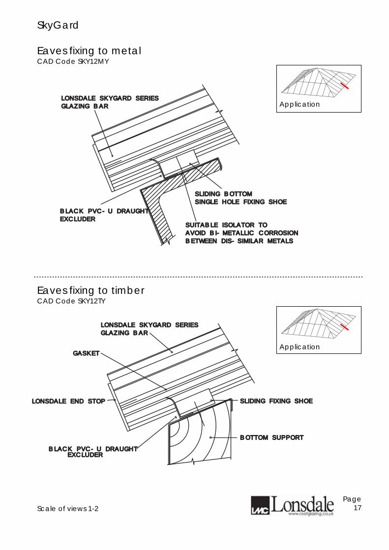
SkyGard Eaves fixing to metal CAD Code SKY12MY
Eaves fixing to timber CAD Code SKY12TY
Scale of views 1-2
Page 17
SLIDING BOTTOMSLIDING BOTTOM
SINGLE HOLE FIXING SHOESINGLE HOLE FIXING SHOE
LONSDALE SKYGARD SERIESLONSDALE SKYGARD SERIES
GLAZING BAR GLAZING BAR
AVOID BI-METALLIC CORROSIONAVOID BI-METALLIC CORROSION
SUITABLE ISOLATOR TOSUITABLE ISOLATOR TO
BETWEEN DIS-SIMILAR METALSBETWEEN DIS-SIMILAR METALS
BLACK PVC-U DRAUGHTBLACK PVC-U DRAUGHT
EXCLUDEREXCLUDER
LONSDALE SKYGARD SERIESLONSDALE SKYGARD SERIES
GLAZING BAR GLAZING BAR
LONSDALE END STOP LONSDALE END STOP
BOTTOM SUPPORTBOTTOM SUPPORT
GASKETGASKET
SLIDING FIXING SHOESLIDING FIXING SHOE
EXCLUDEREXCLUDERBLACK PVC-U DRAUGHT BLACK PVC-U DRAUGHT
Application
Application
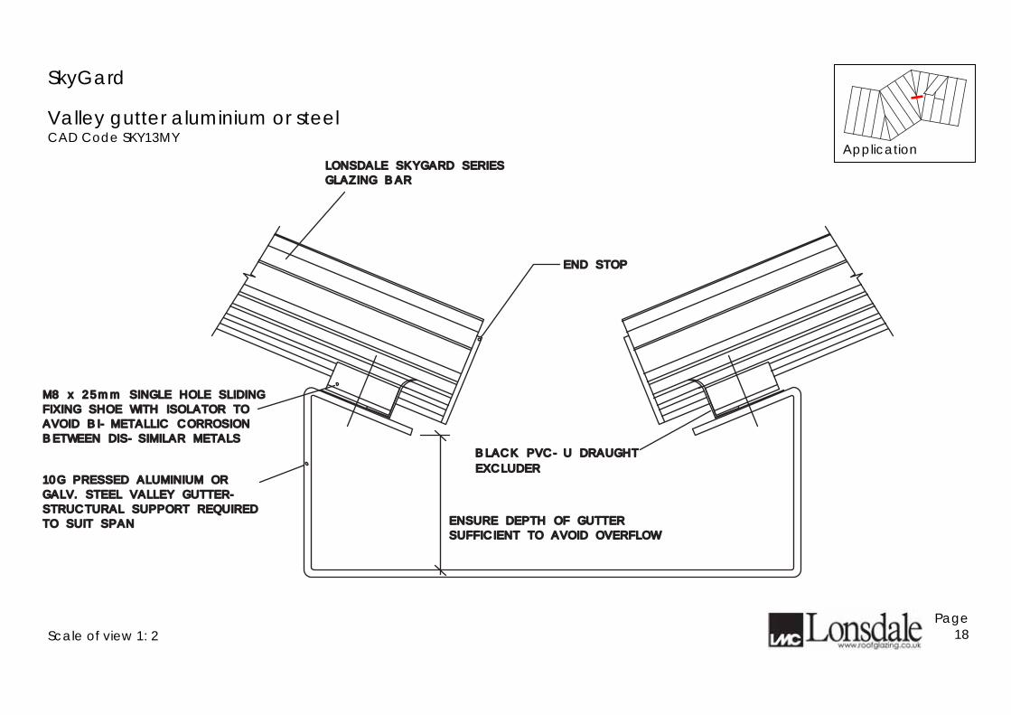
SkyGard
Valley gutter aluminium or steel CAD Code SKY13MY
Scale of view 1: 2
Page 18
END STOPEND STOP
LONSDALE SKYGARD SERIESLONSDALE SKYGARD SERIES
GLAZING BAR GLAZING BAR
M8 x 25mm SINGLE HOLE SLIDINGM8 x 25mm SINGLE HOLE SLIDING
FIXING SHOE WITH ISOLATOR TOFIXING SHOE WITH ISOLATOR TO
AVOID BI-METALLIC CORROSIONAVOID BI-METALLIC CORROSION
BETWEEN DIS-SIMILAR METALSBETWEEN DIS-SIMILAR METALS
ENSURE DEPTH OF GUTTERENSURE DEPTH OF GUTTER
SUFFICIENT TO AVOID OVERFLOWSUFFICIENT TO AVOID OVERFLOW
10G PRESSED ALUMINIUM OR10G PRESSED ALUMINIUM OR
GALV. STEEL VALLEY GUTTER-GALV. STEEL VALLEY GUTTER-
STRUCTURAL SUPPORT REQUIRED STRUCTURAL SUPPORT REQUIRED
TO SUIT SPANTO SUIT SPAN
EXCLUDEREXCLUDER
BLACK PVC-U DRAUGHT BLACK PVC-U DRAUGHT
Application
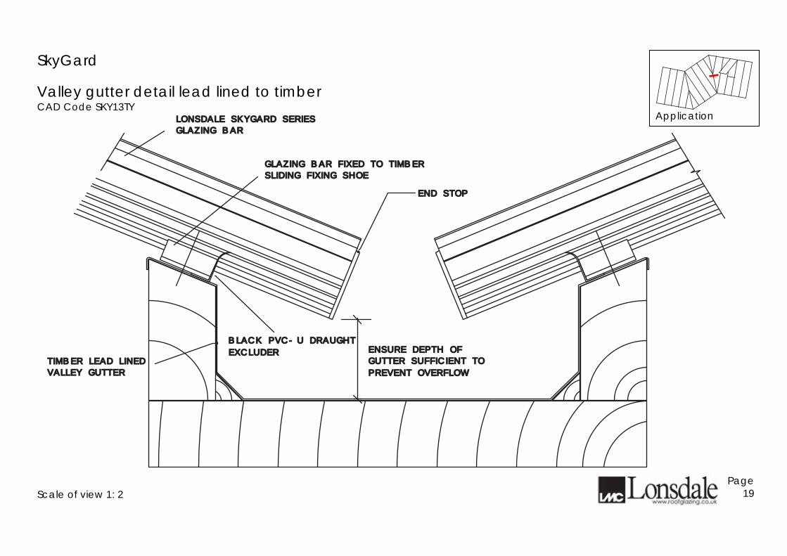
SkyGard
Valley gutter detail lead lined to timber CAD Code SKY13TY
Scale of view 1: 2
Page 19
END STOPEND STOP
LONSDALE SKYGARD SERIESLONSDALE SKYGARD SERIES
GLAZING BAR GLAZING BAR
GLAZING BAR FIXED TO TIMBERGLAZING BAR FIXED TO TIMBER
SLIDING FIXING SHOESLIDING FIXING SHOE
ENSURE DEPTH OF ENSURE DEPTH OF
GUTTER SUFFICIENT TO GUTTER SUFFICIENT TO TIMBER LEAD LINEDTIMBER LEAD LINED
VALLEY GUTTERVALLEY GUTTER PREVENT OVERFLOWPREVENT OVERFLOW
EXCLUDEREXCLUDER
BLACK PVC-U DRAUGHT BLACK PVC-U DRAUGHT
Application
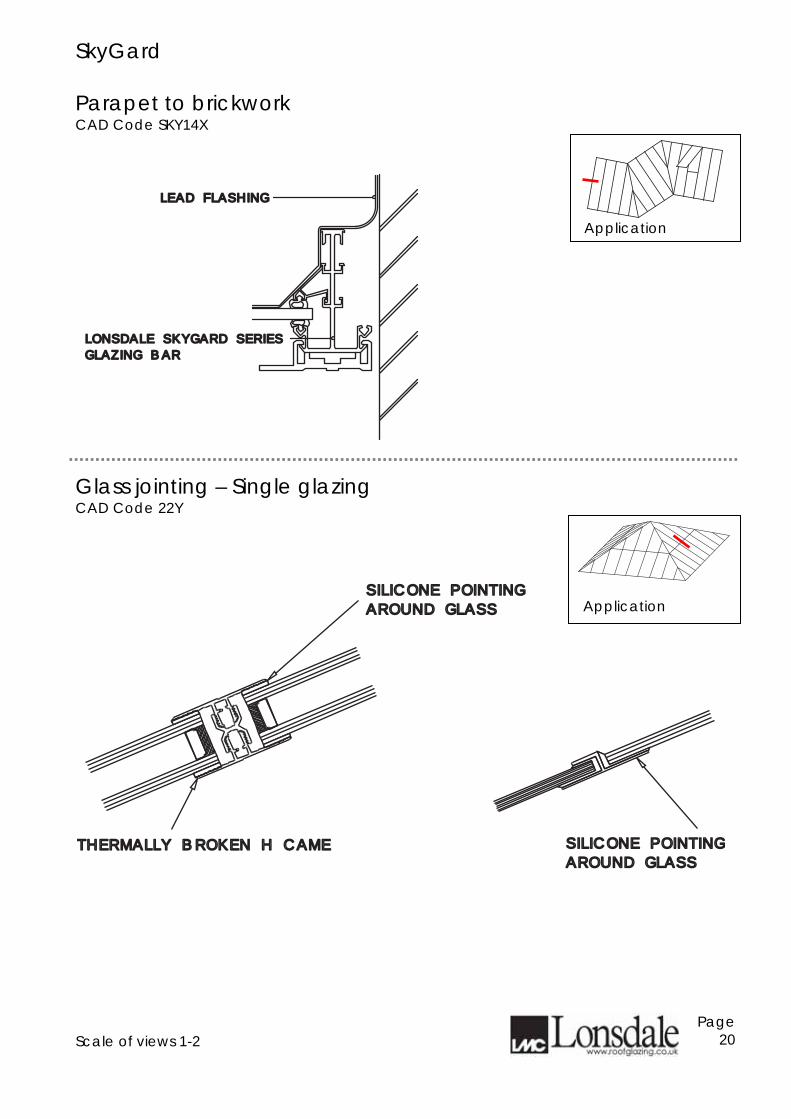
SkyGard Parapet to brickwork CAD Code SKY14X
Glass jointing – Single glazing CAD Code 22Y
Scale of views 1-2
Page 20
LONSDALE SKYGARD SERIESLONSDALE SKYGARD SERIES
GLAZING BARGLAZING BAR
LEAD FLASHINGLEAD FLASHING
Application
Application SILICONE POINTINGSILICONE POINTING
AROUND GLASSAROUND GLASS
THERMALLY BROKEN H CAMETHERMALLY BROKEN H CAME SILICONE POINTINGSILICONE POINTING
AROUND GLASSAROUND GLASS
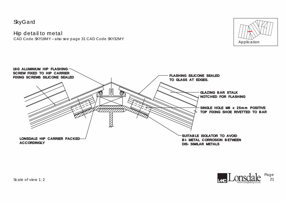
SkyGard
Hip detail to metal CAD Code SKY18MY – also see page 31 CAD Code SKY32MY
Scale of view 1: 2
Page 21
LONSDALE HIP CARRIER PACKEDLONSDALE HIP CARRIER PACKED
ACCORDINGLYACCORDINGLY
SUITABLE ISOLATOR TO AVOIDSUITABLE ISOLATOR TO AVOID
BI-METAL CORROSION BETWEENBI-METAL CORROSION BETWEEN
DIS-SIMILAR METALSDIS-SIMILAR METALS
NOTCHED FOR FLASHINGNOTCHED FOR FLASHING
GLAZING BAR STALK GLAZING BAR STALK
SCREW FIXED TO HIP CARRIERSCREW FIXED TO HIP CARRIER
16G ALUMINIUM HIP FLASHING16G ALUMINIUM HIP FLASHING
FIXING SCREWS SILICONE SEALEDFIXING SCREWS SILICONE SEALED
SINGLE HOLE M8 x 25mm POSITIVESINGLE HOLE M8 x 25mm POSITIVE
TOP FIXING SHOE RIVETTED TO BARTOP FIXING SHOE RIVETTED TO BAR
TO GLASS AT EDGES.TO GLASS AT EDGES.
FLASHING SILICONE SEALEDFLASHING SILICONE SEALED
Application
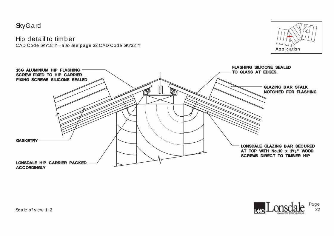
SkyGard
Hip detail to timber CAD Code SKY18TY – also see page 32 CAD Code SKY32TY
Scale of view 1: 2
Page 22
GASKETRYGASKETRY
LONSDALE GLAZING BAR SECUREDLONSDALE GLAZING BAR SECURED
AT TOP WITH No.10 x 1 " WOODAT TOP WITH No.10 x 1 " WOOD
SCREWS DIRECT TO TIMBER HIPSCREWS DIRECT TO TIMBER HIP
LONSDALE HIP CARRIER PACKEDLONSDALE HIP CARRIER PACKED
ACCORDINGLYACCORDINGLY
1/2
GLAZING BAR STALK GLAZING BAR STALK
NOTCHED FOR FLASHINGNOTCHED FOR FLASHING
SCREW FIXED TO HIP CARRIERSCREW FIXED TO HIP CARRIER
16G ALUMINIUM HIP FLASHING16G ALUMINIUM HIP FLASHING
FIXING SCREWS SILICONE SEALEDFIXING SCREWS SILICONE SEALED
TO GLASS AT EDGES.TO GLASS AT EDGES.
FLASHING SILICONE SEALEDFLASHING SILICONE SEALED
Application
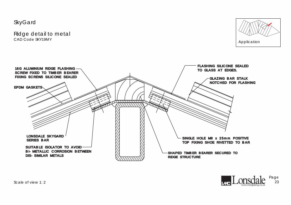
SkyGard
Ridge detail to metal CAD Code SKY19MY
Scale of view 1: 2
Page 23
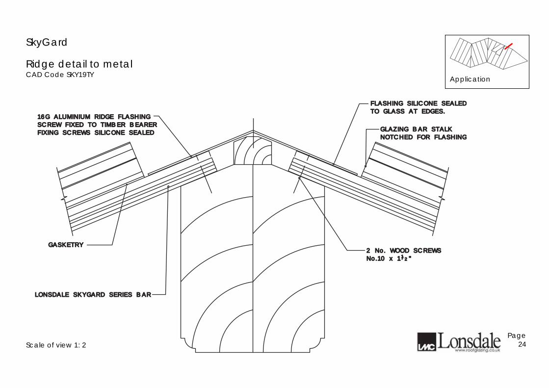
EPDM GASKETSEPDM GASKETS
LONSDALE SKYGARD LONSDALE SKYGARD
TOP FIXING SHOE RIVETTED TO BARTOP FIXING SHOE RIVETTED TO BAR
SINGLE HOLE M8 x 25mm POSITIVESINGLE HOLE M8 x 25mm POSITIVE
BI-METALLIC CORROSION BETWEENBI-METALLIC CORROSION BETWEEN
SUITABLE ISOLATOR TO AVOIDSUITABLE ISOLATOR TO AVOID
DIS-SIMILAR METALSDIS-SIMILAR METALS
SERIES BARSERIES BAR
GLAZING BAR STALK GLAZING BAR STALK
NOTCHED FOR FLASHINGNOTCHED FOR FLASHING
FIXING SCREWS SILICONE SEALEDFIXING SCREWS SILICONE SEALED
16G ALUMINIUM RIDGE FLASHING16G ALUMINIUM RIDGE FLASHING
SCREW FIXED TO TIMBER BEARER SCREW FIXED TO TIMBER BEARER
SHAPED TIMBER BEARER SECURED TO SHAPED TIMBER BEARER SECURED TO
RIDGE STRUCTURERIDGE STRUCTURE
TO GLASS AT EDGES.TO GLASS AT EDGES.
FLASHING SILICONE SEALEDFLASHING SILICONE SEALED
Application
SkyGard
Ridge detail to metal CAD Code SKY19TY
Scale of view 1: 2
Page 24
2 No. WOOD SCREWS2 No. WOOD SCREWS
No.10 x 1 "No.10 x 1 "
GASKETRYGASKETRY
LONSDALE SKYGARD SERIES BARLONSDALE SKYGARD SERIES BAR
11//22
GLAZING BAR STALK GLAZING BAR STALK
NOTCHED FOR FLASHINGNOTCHED FOR FLASHING
SCREW FIXED TO TIMBER BEARER SCREW FIXED TO TIMBER BEARER
16G ALUMINIUM RIDGE FLASHING16G ALUMINIUM RIDGE FLASHING
FIXING SCREWS SILICONE SEALEDFIXING SCREWS SILICONE SEALED
TO GLASS AT EDGES.TO GLASS AT EDGES.
FLASHING SILICONE SEALEDFLASHING SILICONE SEALED
Application
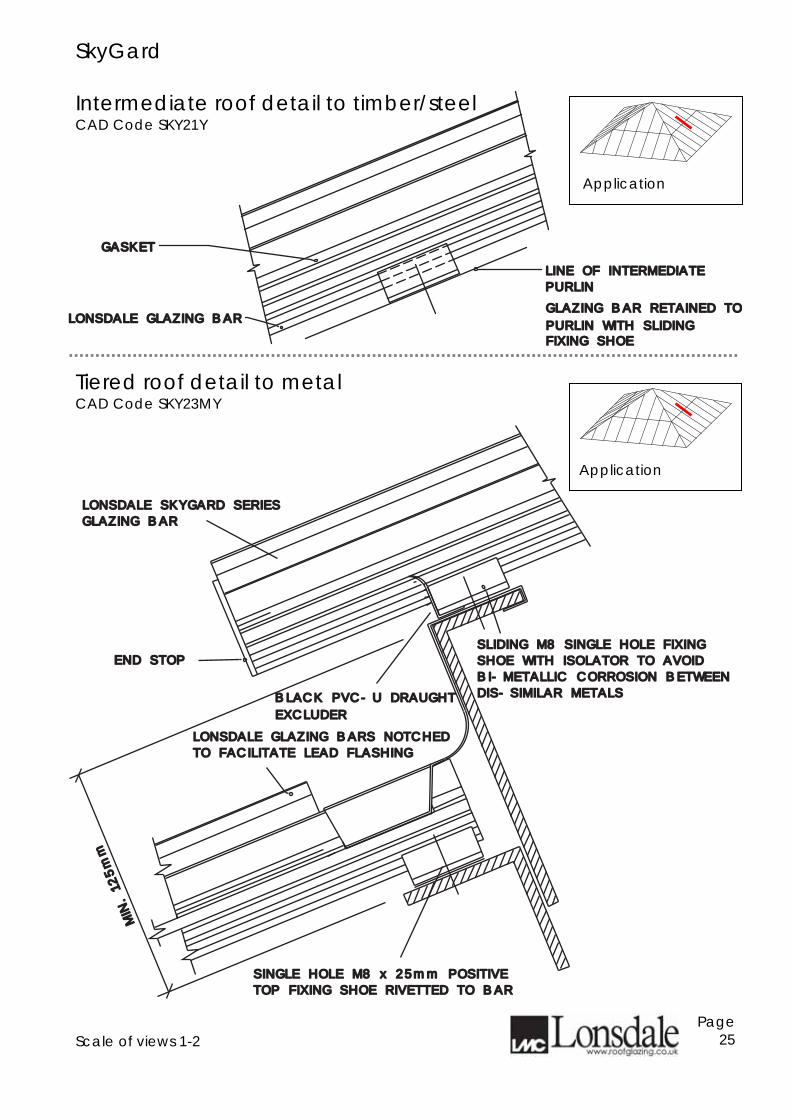
SkyGard Intermediate roof detail to timber/steel CAD Code SKY21Y
Tiered roof detail to metal CAD Code SKY23MY
Scale of views 1-2
Page 25
GLAZING BAR RETAINED TOGLAZING BAR RETAINED TO
PURLIN WITH SLIDING PURLIN WITH SLIDING LONSDALE GLAZING BARLONSDALE GLAZING BAR
GASKETGASKET
FIXING SHOEFIXING SHOE
PURLINPURLIN
LINE OF INTERMEDIATELINE OF INTERMEDIATE
LONSDALE SKYGARD SERIESLONSDALE SKYGARD SERIES
GLAZING BAR GLAZING BAR
LONSDALE GLAZING BARS NOTCHEDLONSDALE GLAZING BARS NOTCHED
TO FACILITATE LEAD FLASHING TO FACILITATE LEAD FLASHING
END STOPEND STOPSLIDING M8 SINGLE HOLE FIXINGSLIDING M8 SINGLE HOLE FIXING
SHOE WITH ISOLATOR TO AVOIDSHOE WITH ISOLATOR TO AVOID
BI-METALLIC CORROSION BETWEENBI-METALLIC CORROSION BETWEEN
DIS-SIMILAR METALSDIS-SIMILAR METALS
MIN. 125mm
MIN. 125mm
SINGLE HOLE M8 x 25mm POSITIVESINGLE HOLE M8 x 25mm POSITIVE
TOP FIXING SHOE RIVETTED TO BARTOP FIXING SHOE RIVETTED TO BAR
EXCLUDEREXCLUDER
BLACK PVC-U DRAUGHT BLACK PVC-U DRAUGHT
Application
Application
SkyGard
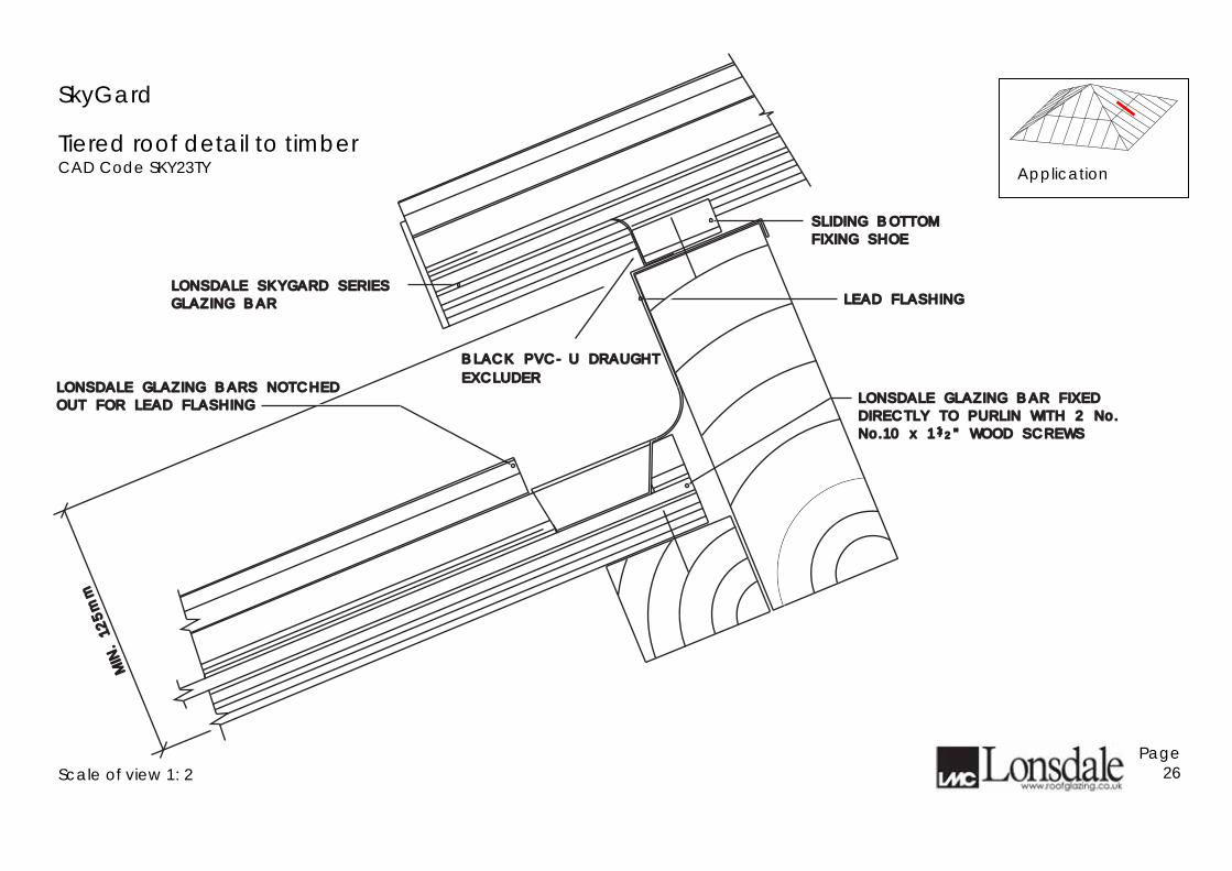
Tiered roof detail to timber CAD Code SKY23TY
Scale of view 1: 2
Page 26
LEAD FLASHINGLEAD FLASHINGLONSDALE SKYGARD SERIESLONSDALE SKYGARD SERIES
GLAZING BAR GLAZING BAR
LONSDALE GLAZING BAR FIXEDLONSDALE GLAZING BAR FIXED
DIRECTLY TO PURLIN WITH 2 No.DIRECTLY TO PURLIN WITH 2 No.
No.10 x 1 " WOOD SCREWSNo.10 x 1 " WOOD SCREWS
LONSDALE GLAZING BARS NOTCHEDLONSDALE GLAZING BARS NOTCHED
OUT FOR LEAD FLASHING OUT FOR LEAD FLASHING
/1 2
MIN. 125mm
MIN. 125mm
SLIDING BOTTOMSLIDING BOTTOM
FIXING SHOEFIXING SHOE
EXCLUDEREXCLUDER
BLACK PVC-U DRAUGHT BLACK PVC-U DRAUGHT
Application
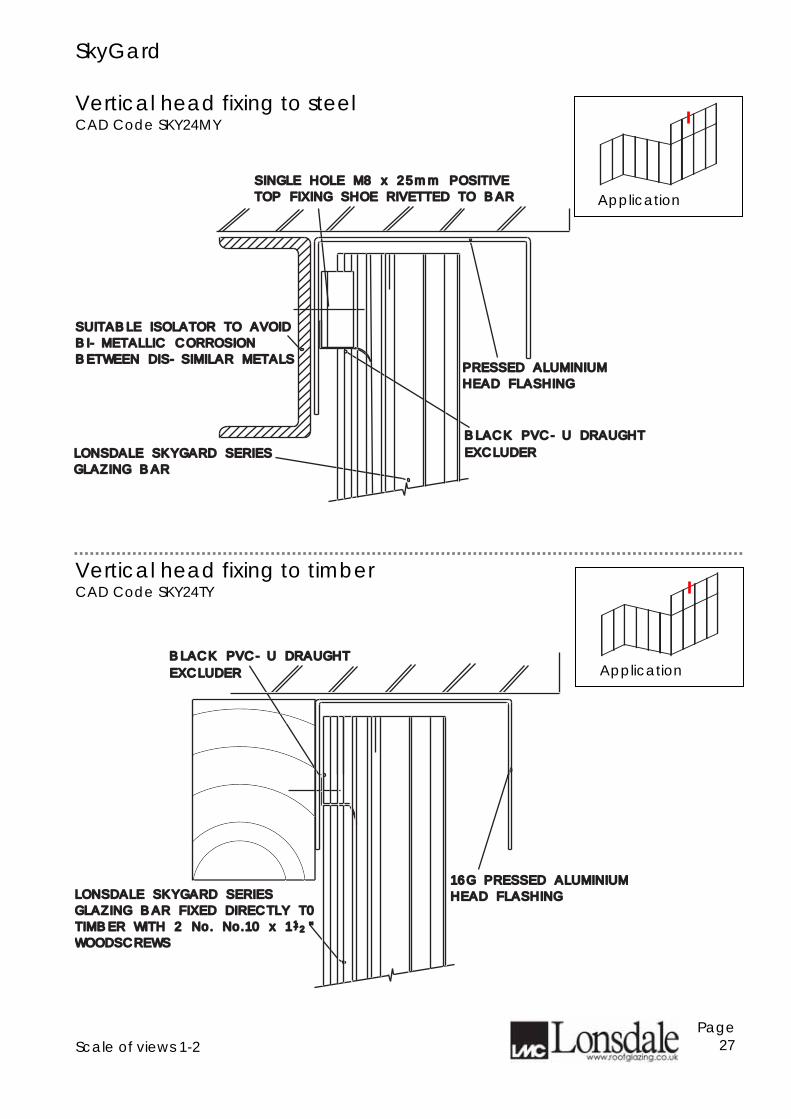
SkyGard Vertical head fixing to steel CAD Code SKY24MY
Vertical head fixing to timber CAD Code SKY24TY
Scale of views 1-2
Page 27
PRESSED ALUMINIUMPRESSED ALUMINIUM
HEAD FLASHINGHEAD FLASHING
LONSDALE SKYGARD SERIES LONSDALE SKYGARD SERIES
GLAZING BARGLAZING BAR
SUITABLE ISOLATOR TO AVOIDSUITABLE ISOLATOR TO AVOID
BI-METALLIC CORROSIONBI-METALLIC CORROSION
BETWEEN DIS-SIMILAR METALSBETWEEN DIS-SIMILAR METALS
SINGLE HOLE M8 x 25mm POSITIVESINGLE HOLE M8 x 25mm POSITIVE
TOP FIXING SHOE RIVETTED TO BARTOP FIXING SHOE RIVETTED TO BAR
EXCLUDEREXCLUDER
BLACK PVC-U DRAUGHT BLACK PVC-U DRAUGHT
16G PRESSED ALUMINIUM16G PRESSED ALUMINIUM
HEAD FLASHINGHEAD FLASHINGLONSDALE SKYGARD SERIESLONSDALE SKYGARD SERIES
GLAZING BAR FIXED DIRECTLY T0 GLAZING BAR FIXED DIRECTLY T0
TIMBER WITH 2 No. No.10 x 1 "TIMBER WITH 2 No. No.10 x 1 "
WOODSCREWSWOODSCREWS
1/2
EXCLUDEREXCLUDER
BLACK PVC-U DRAUGHT BLACK PVC-U DRAUGHT
Application
Application
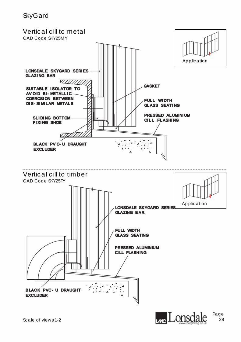
SkyGard Vertical cill to metal CAD Code SKY25MY
Vertical cill to timber CAD Code SKY25TY
Scale of views 1-2
Page 28
PRESSED ALUMINIUMPRESSED ALUMINIUMCILL FLASHINGCILL FLASHING
LONSDALE SKYGARD SERIESLONSDALE SKYGARD SERIESGLAZING BARGLAZING BAR
SUITABLE ISOLATOR TOSUITABLE ISOLATOR TOAVOID BI-METALLICAVOID BI-METALLICCORROSION BETWEENCORROSION BETWEENDIS-SIMILAR METALSDIS-SIMILAR METALS
GASKETGASKET
FIXING SHOEFIXING SHOESLIDING BOTTOMSLIDING BOTTOM
FULL WIDTH FULL WIDTH GLASS SEATINGGLASS SEATING
EXCLUDEREXCLUDERBLACK PVC-U DRAUGHT BLACK PVC-U DRAUGHT
LONSDALE SKYGARD SERIESLONSDALE SKYGARD SERIES
PRESSED ALUMINIUMPRESSED ALUMINIUM
CILL FLASHINGCILL FLASHING
GLAZING BAR.GLAZING BAR.
FULL WIDTHFULL WIDTH
GLASS SEATINGGLASS SEATING
EXCLUDEREXCLUDER
BLACK PVC-U DRAUGHT BLACK PVC-U DRAUGHT
Application
Application
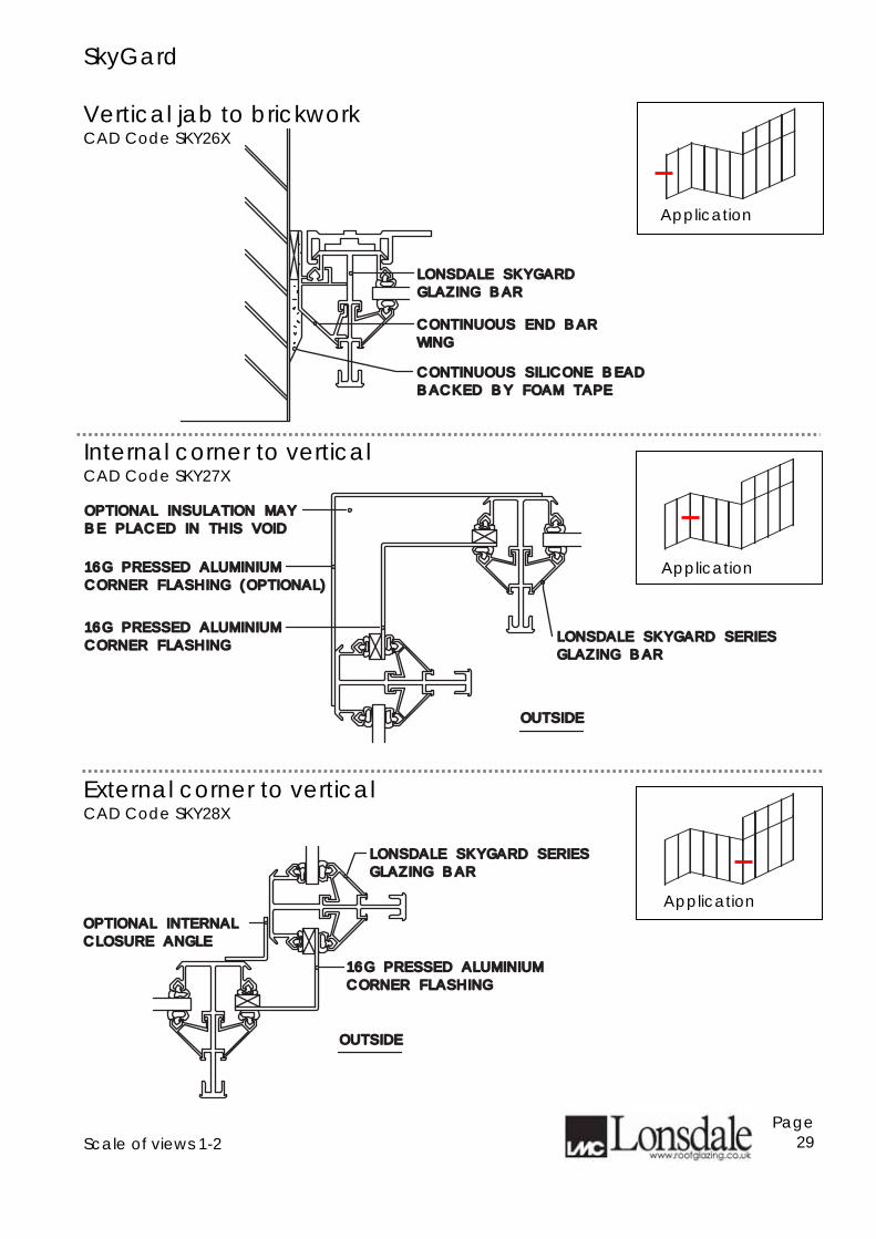
SkyGard Vertical jab to brickwork CAD Code SKY26X
Internal corner to vertical CAD Code SKY27X
External corner to vertical CAD Code SKY28X
Scale of views 1-2
Page 29
CONTINUOUS END BARCONTINUOUS END BAR
WINGWING
LONSDALE SKYGARDLONSDALE SKYGARD
GLAZING BARGLAZING BAR
CONTINUOUS SILICONE BEADCONTINUOUS SILICONE BEAD
BACKED BY FOAM TAPEBACKED BY FOAM TAPE
OPTIONAL INSULATION MAYOPTIONAL INSULATION MAY
BE PLACED IN THIS VOIDBE PLACED IN THIS VOID
16G PRESSED ALUMINIUM16G PRESSED ALUMINIUM
CORNER FLASHING (OPTIONAL)CORNER FLASHING (OPTIONAL)
CORNER FLASHINGCORNER FLASHING
16G PRESSED ALUMINIUM16G PRESSED ALUMINIUM
OUTSIDEOUTSIDE
LONSDALE SKYGARD SERIES LONSDALE SKYGARD SERIES
GLAZING BAR GLAZING BAR
LONSDALE SKYGARD SERIES LONSDALE SKYGARD SERIES
GLAZING BAR GLAZING BAR
CORNER FLASHINGCORNER FLASHING
16G PRESSED ALUMINIUM16G PRESSED ALUMINIUM
OUTSIDEOUTSIDE
OPTIONAL INTERNALOPTIONAL INTERNAL
CLOSURE ANGLECLOSURE ANGLE
Application
Application
Application
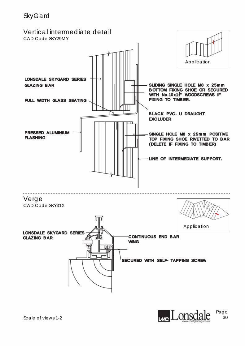
SkyGard Vertical intermediate detail CAD Code SKY29MY
Verge CAD Code SKY31X
Scale of views 1-2
Page 30
PRESSED ALUMINIUM PRESSED ALUMINIUM
LONSDALE SKYGARD SERIESLONSDALE SKYGARD SERIES
GLAZING BARGLAZING BARBOTTOM FIXING SHOE OR SECUREDBOTTOM FIXING SHOE OR SECUREDSLIDING SINGLE HOLE M8 x 25mmSLIDING SINGLE HOLE M8 x 25mm
FLASHINGFLASHINGSINGLE HOLE M8 x 25mm POSITIVESINGLE HOLE M8 x 25mm POSITIVE
TOP FIXING SHOE RIVETTED TO BARTOP FIXING SHOE RIVETTED TO BAR
WITH No.10x1WITH No.10x11122" WOODSCREWS IF" WOODSCREWS IF
FIXING TO TIMBER.FIXING TO TIMBER.
LINE OF INTERMEDIATE SUPPORT.LINE OF INTERMEDIATE SUPPORT.
FULL WIDTH GLASS SEATINGFULL WIDTH GLASS SEATING
(DELETE IF FIXING TO TIMBER)(DELETE IF FIXING TO TIMBER)
EXCLUDEREXCLUDER
BLACK PVC-U DRAUGHT BLACK PVC-U DRAUGHT
CONTINUOUS END BARCONTINUOUS END BAR
WINGWING
LONSDALE SKYGARD SERIESLONSDALE SKYGARD SERIES
GLAZING BARGLAZING BAR
SECURED WITH SELF-TAPPING SCREWSECURED WITH SELF-TAPPING SCREW
Application
Application
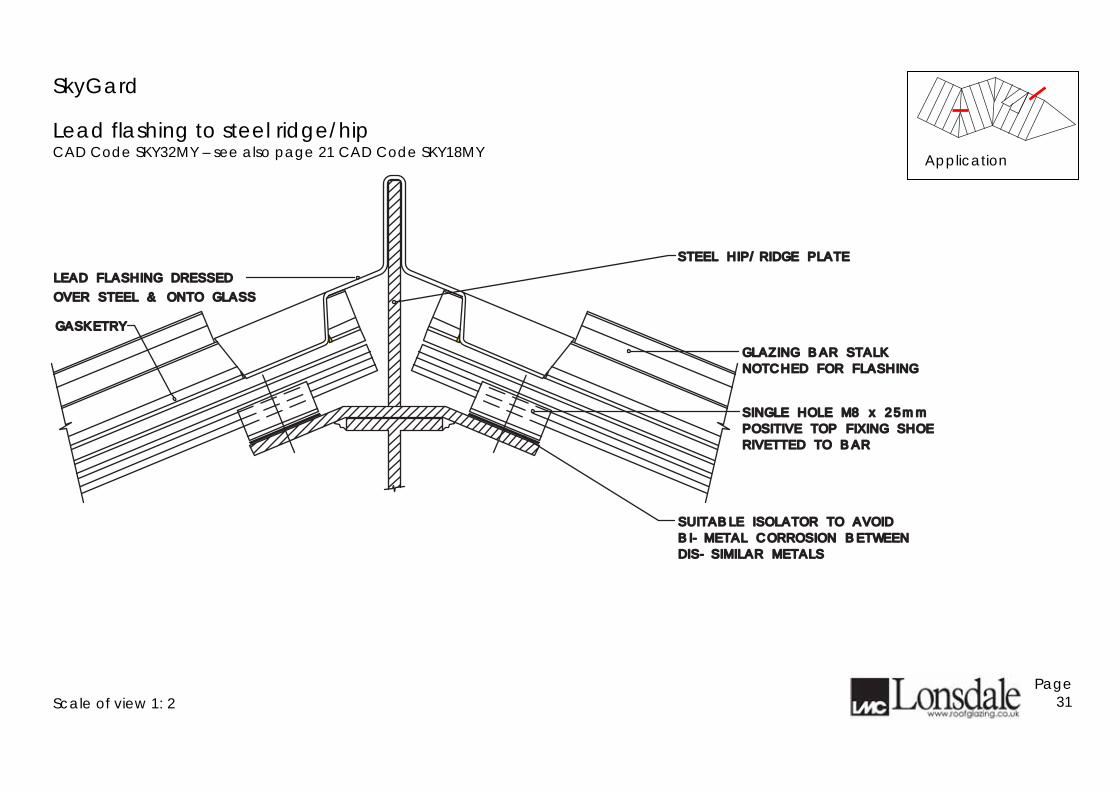
SkyGard
Lead flashing to steel ridge/hip CAD Code SKY32MY – see also page 21 CAD Code SKY18MY
Scale of view 1: 2
Page 31
LEAD FLASHING DRESSEDLEAD FLASHING DRESSED
SINGLE HOLE M8 x 25mmSINGLE HOLE M8 x 25mm
POSITIVE TOP FIXING SHOEPOSITIVE TOP FIXING SHOE
RIVETTED TO BARRIVETTED TO BAR
SUITABLE ISOLATOR TO AVOIDSUITABLE ISOLATOR TO AVOID
BI-METAL CORROSION BETWEENBI-METAL CORROSION BETWEEN
DIS-SIMILAR METALSDIS-SIMILAR METALS
GASKETRYGASKETRY
NOTCHED FOR FLASHINGNOTCHED FOR FLASHING
GLAZING BAR STALK GLAZING BAR STALK
OVER STEEL & ONTO GLASSOVER STEEL & ONTO GLASS
STEEL HIP/RIDGE PLATESTEEL HIP/RIDGE PLATE
Application
SkyGard
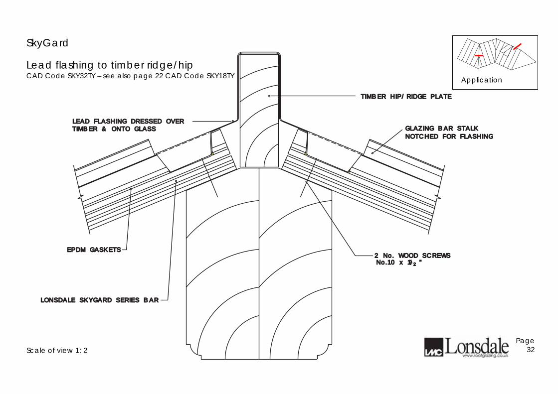
Lead flashing to timber ridge/hip CAD Code SKY32TY – see also page 22 CAD Code SKY18TY
Scale of view 1: 2
Page 32
2 No. WOOD SCREWS2 No. WOOD SCREWSNo.10 x 1 "No.10 x 1 "
EPDM GASKETSEPDM GASKETS
LONSDALE SKYGARD SERIES BARLONSDALE SKYGARD SERIES BAR
11//22
LEAD FLASHING DRESSED OVERLEAD FLASHING DRESSED OVERGLAZING BAR STALK GLAZING BAR STALK
NOTCHED FOR FLASHINGNOTCHED FOR FLASHINGTIMBER & ONTO GLASSTIMBER & ONTO GLASS
TIMBER HIP/RIDGE PLATETIMBER HIP/RIDGE PLATE
Application
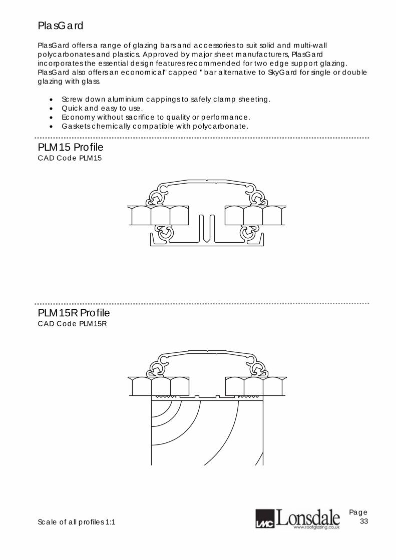
PlasGard PlasGard offers a range of glazing bars and accessories to suit solid and multi-wall polycarbonates and plastics. Approved by major sheet manufacturers, PlasGard incorporates the essential design features recommended for two edge support glazing. PlasGard also offers an economical" capped " bar alternative to SkyGard for single or double glazing with glass.
• Screw down aluminium cappings to safely clamp sheeting. • Quick and easy to use. • Economy without sacrifice to quality or performance. • Gaskets chemically compatible with polycarbonate.
PLM15 Profile CAD Code PLM15
PLM15R Profile CAD Code PLM15R
Scale of all profiles 1:1
Page 33
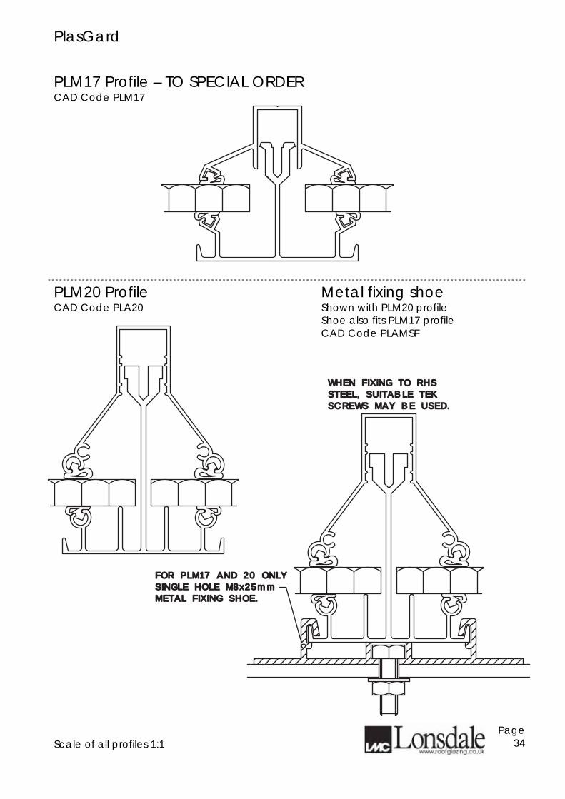
PlasGard PLM17 Profile – TO SPECIAL ORDER CAD Code PLM17
PLM20 Profile CAD Code PLA20
Metal fixing shoe Shown with PLM20 profile Shoe also fits PLM17 profile CAD Code PLAMSF
Scale of all profiles 1:1
Page 34
METAL FIXING SHOE.METAL FIXING SHOE.
SINGLE HOLE M8x25mmSINGLE HOLE M8x25mm
FOR PLM17 AND 20 ONLYFOR PLM17 AND 20 ONLY
WHEN FIXING TO RHSWHEN FIXING TO RHS
STEEL, SUITABLE TEKSTEEL, SUITABLE TEK
SCREWS MAY BE USED.SCREWS MAY BE USED.
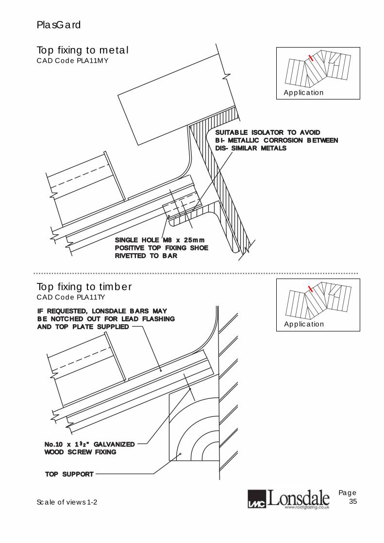
PlasGard Top fixing to metal CAD Code PLA11MY
Top fixing to timber CAD Code PLA11TY
Scale of views 1-2
Page 35
SINGLE HOLE M8 x 25mmSINGLE HOLE M8 x 25mm
POSITIVE TOP FIXING SHOEPOSITIVE TOP FIXING SHOE
RIVETTED TO BARRIVETTED TO BAR
DIS-SIMILAR METALSDIS-SIMILAR METALS
BI-METALLIC CORROSION BETWEENBI-METALLIC CORROSION BETWEEN
SUITABLE ISOLATOR TO AVOIDSUITABLE ISOLATOR TO AVOID
No.10 x 1 " GALVANIZEDNo.10 x 1 " GALVANIZEDWOOD SCREW FIXINGWOOD SCREW FIXING
11//22
TOP SUPPORTTOP SUPPORT
IF REQUESTED, LONSDALE BARS MAY IF REQUESTED, LONSDALE BARS MAY
BE NOTCHED OUT FOR LEAD FLASHINGBE NOTCHED OUT FOR LEAD FLASHING
AND TOP PLATE SUPPLIEDAND TOP PLATE SUPPLIED
Application
Application
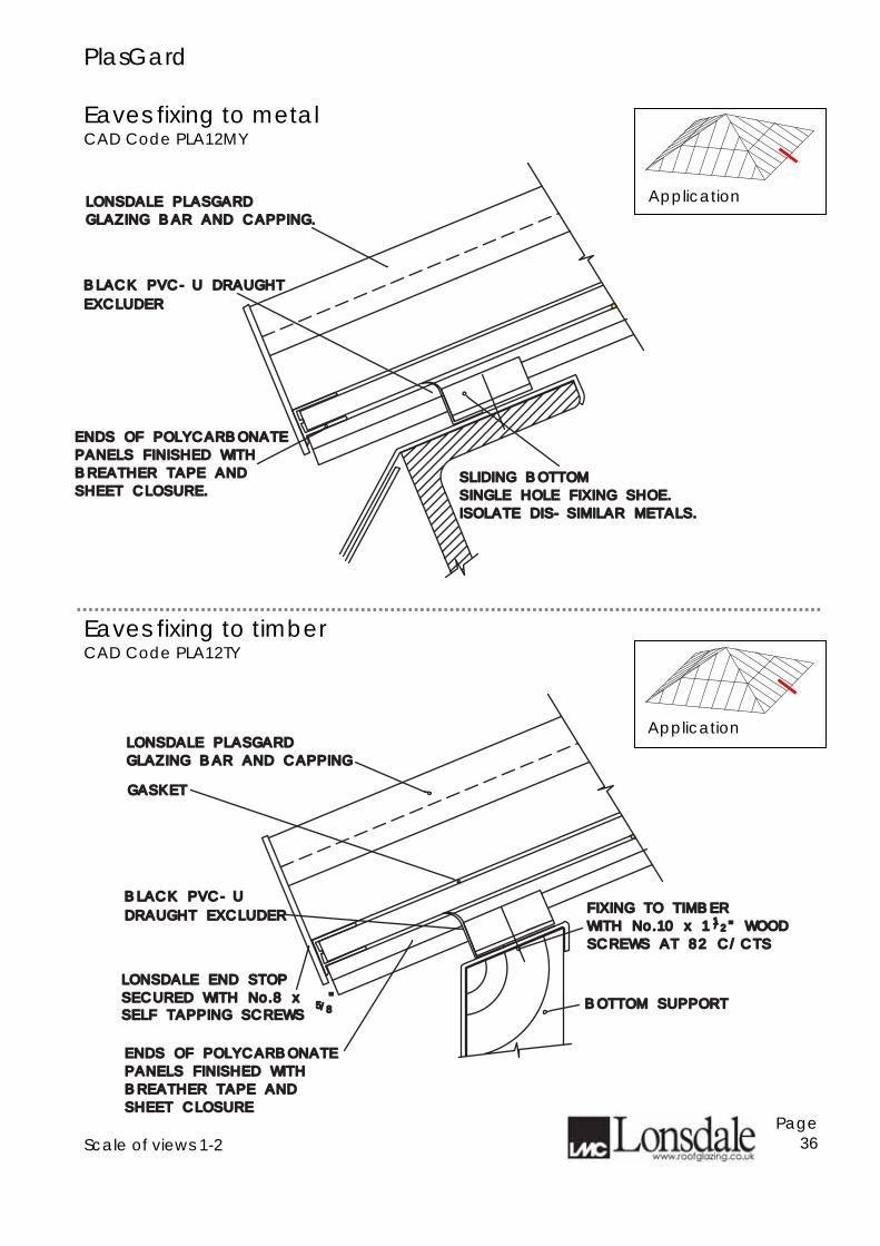
PlasGard Eaves fixing to metal CAD Code PLA12MY
Eaves fixing to timber CAD Code PLA12TY
Scale of views 1-2
Page 36
LONSDALE PLASGARDLONSDALE PLASGARD
GLAZING BAR AND CAPPING.GLAZING BAR AND CAPPING.
SLIDING BOTTOMSLIDING BOTTOM
SINGLE HOLE FIXING SHOE.SINGLE HOLE FIXING SHOE.
ENDS OF POLYCARBONATEENDS OF POLYCARBONATE
PANELS FINISHED WITHPANELS FINISHED WITH
BREATHER TAPE ANDBREATHER TAPE AND
SHEET CLOSURE.SHEET CLOSURE.
ISOLATE DIS-SIMILAR METALS.ISOLATE DIS-SIMILAR METALS.
EXCLUDEREXCLUDER
BLACK PVC-U DRAUGHT BLACK PVC-U DRAUGHT
LONSDALE PLASGARDLONSDALE PLASGARD
GLAZING BAR AND CAPPINGGLAZING BAR AND CAPPING
FIXING TO TIMBERFIXING TO TIMBER
WITH No.10 x 1 " WOODWITH No.10 x 1 " WOOD
SCREWS AT 82 C/CTSSCREWS AT 82 C/CTS
11//22
SECURED WITH No.8 x " SECURED WITH No.8 x "
LONSDALE END STOP LONSDALE END STOP
BOTTOM SUPPORTBOTTOM SUPPORTSELF TAPPING SCREWSSELF TAPPING SCREWS
GASKETGASKET
55//88
ENDS OF POLYCARBONATEENDS OF POLYCARBONATE
PANELS FINISHED WITHPANELS FINISHED WITH
BREATHER TAPE ANDBREATHER TAPE AND
SHEET CLOSURESHEET CLOSURE
DRAUGHT EXCLUDERDRAUGHT EXCLUDER
BLACK PVC-UBLACK PVC-U
Application
Application
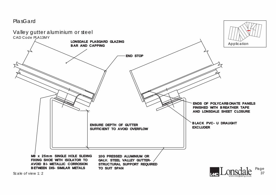
PlasGard
Valley gutter aluminium or steel CAD Code PLA13MY
Scale of view 1: 2
Page 37
END STOPEND STOP
ENDS OF POLYCARBONATE PANELSENDS OF POLYCARBONATE PANELS
FINISHED WITH BREATHER TAPEFINISHED WITH BREATHER TAPE
AND LONSDALE SHEET CLOSUREAND LONSDALE SHEET CLOSURE
LONSDALE PLASGARD GLAZINGLONSDALE PLASGARD GLAZING
BAR AND CAPPINGBAR AND CAPPING
M8 x 25mm SINGLE HOLE SLIDINGM8 x 25mm SINGLE HOLE SLIDING
FIXING SHOE WITH ISOLATOR TOFIXING SHOE WITH ISOLATOR TO
AVOID BI-METALLIC CORROSIONAVOID BI-METALLIC CORROSION
BETWEEN DIS-SIMILAR METALSBETWEEN DIS-SIMILAR METALS
ENSURE DEPTH OF GUTTERENSURE DEPTH OF GUTTER
SUFFICIENT TO AVOID OVERFLOWSUFFICIENT TO AVOID OVERFLOW
10G PRESSED ALUMINIUM OR10G PRESSED ALUMINIUM OR
GALV. STEEL VALLEY GUTTER-GALV. STEEL VALLEY GUTTER-
STRUCTURAL SUPPORT REQUIRED STRUCTURAL SUPPORT REQUIRED
TO SUIT SPANTO SUIT SPAN
EXCLUDEREXCLUDER
BLACK PVC-U DRAUGHT BLACK PVC-U DRAUGHT
Application
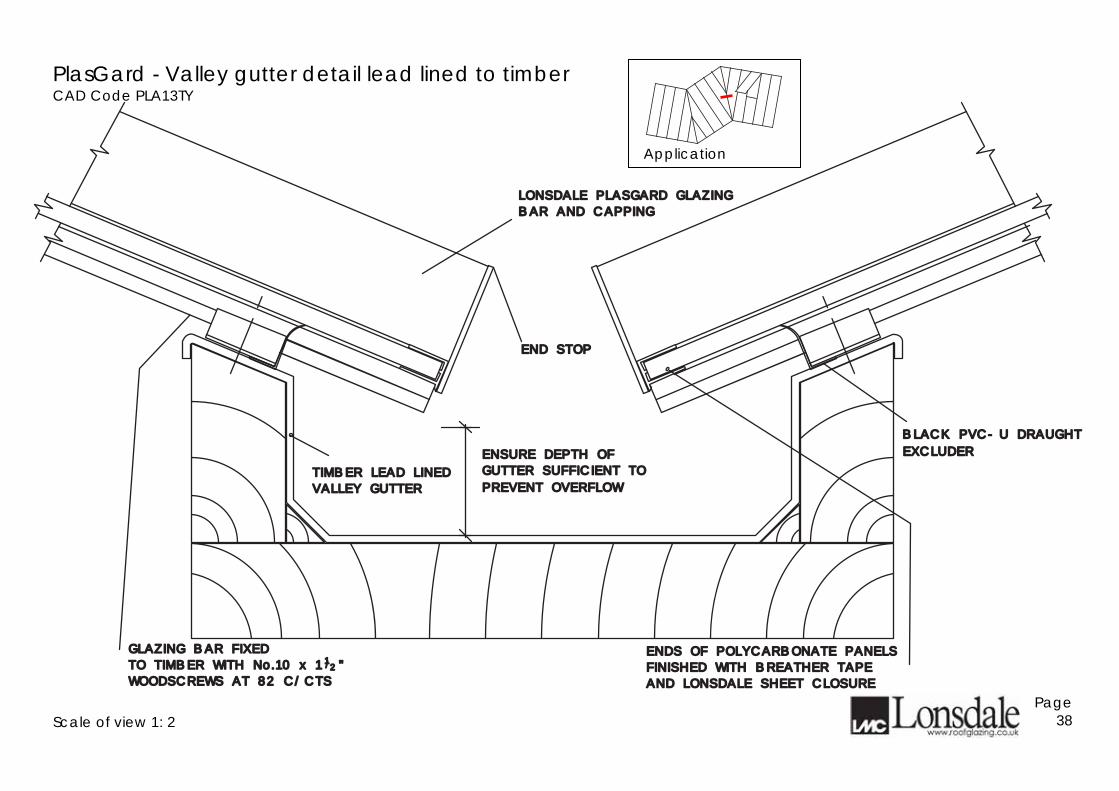
PlasGard - Valley gutter detail lead lined to timber CAD Code PLA13TY
Scale of view 1: 2
Page 38
END STOPEND STOP
ENDS OF POLYCARBONATE PANELSENDS OF POLYCARBONATE PANELS
FINISHED WITH BREATHER TAPEFINISHED WITH BREATHER TAPE
AND LONSDALE SHEET CLOSUREAND LONSDALE SHEET CLOSURE
LONSDALE PLASGARD GLAZINGLONSDALE PLASGARD GLAZING
BAR AND CAPPINGBAR AND CAPPING
GLAZING BAR FIXEDGLAZING BAR FIXED
TO TIMBER WITH No.10 x 1 "TO TIMBER WITH No.10 x 1 "
WOODSCREWS AT 82 C/CTSWOODSCREWS AT 82 C/CTS
ENSURE DEPTH OF ENSURE DEPTH OF
GUTTER SUFFICIENT TO GUTTER SUFFICIENT TO TIMBER LEAD LINEDTIMBER LEAD LINED
VALLEY GUTTERVALLEY GUTTER PREVENT OVERFLOWPREVENT OVERFLOW
11//22
EXCLUDEREXCLUDER
BLACK PVC-U DRAUGHT BLACK PVC-U DRAUGHT
Application
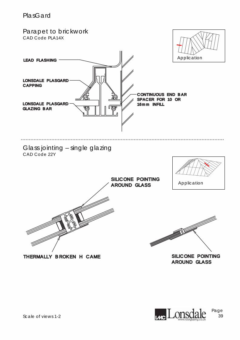
PlasGard Parapet to brickwork CAD Code PLA14X
Glass jointing – single glazing CAD Code 22Y
Scale of views 1-2
Page 39
CONTINUOUS END BARCONTINUOUS END BAR
SPACER FOR 10 OR SPACER FOR 10 OR
16mm INFILL16mm INFILL
LONSDALE PLASGARDLONSDALE PLASGARD
CAPPINGCAPPING
LONSDALE PLASGARDLONSDALE PLASGARD
GLAZING BARGLAZING BAR
LEAD FLASHINGLEAD FLASHING
Application
SILICONE POINTINGSILICONE POINTING
AROUND GLASSAROUND GLASS
THERMALLY BROKEN H CAMETHERMALLY BROKEN H CAME SILICONE POINTINGSILICONE POINTING
AROUND GLASSAROUND GLASS
Application
PlasGard
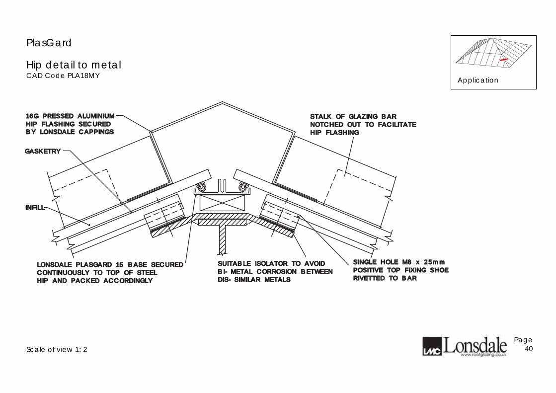
Hip detail to metal CAD Code PLA18MY
Scale of view 1: 2
Page 40
16G PRESSED ALUMINIUM16G PRESSED ALUMINIUM
HIP FLASHING SECUREDHIP FLASHING SECURED
GASKETRYGASKETRY
STALK OF GLAZING BARSTALK OF GLAZING BAR
NOTCHED OUT TO FACILITATENOTCHED OUT TO FACILITATE
HIP FLASHINGHIP FLASHING
SINGLE HOLE M8 x 25mmSINGLE HOLE M8 x 25mm
POSITIVE TOP FIXING SHOEPOSITIVE TOP FIXING SHOE
RIVETTED TO BARRIVETTED TO BAR
LONSDALE PLASGARD 15 BASE SECUREDLONSDALE PLASGARD 15 BASE SECURED
CONTINUOUSLY TO TOP OF STEELCONTINUOUSLY TO TOP OF STEEL
HIP AND PACKED ACCORDINGLYHIP AND PACKED ACCORDINGLY
BY LONSDALE CAPPINGSBY LONSDALE CAPPINGS
INFILLINFILL
SUITABLE ISOLATOR TO AVOIDSUITABLE ISOLATOR TO AVOID
BI-METAL CORROSION BETWEENBI-METAL CORROSION BETWEEN
DIS-SIMILAR METALSDIS-SIMILAR METALS
Application
PlasGard
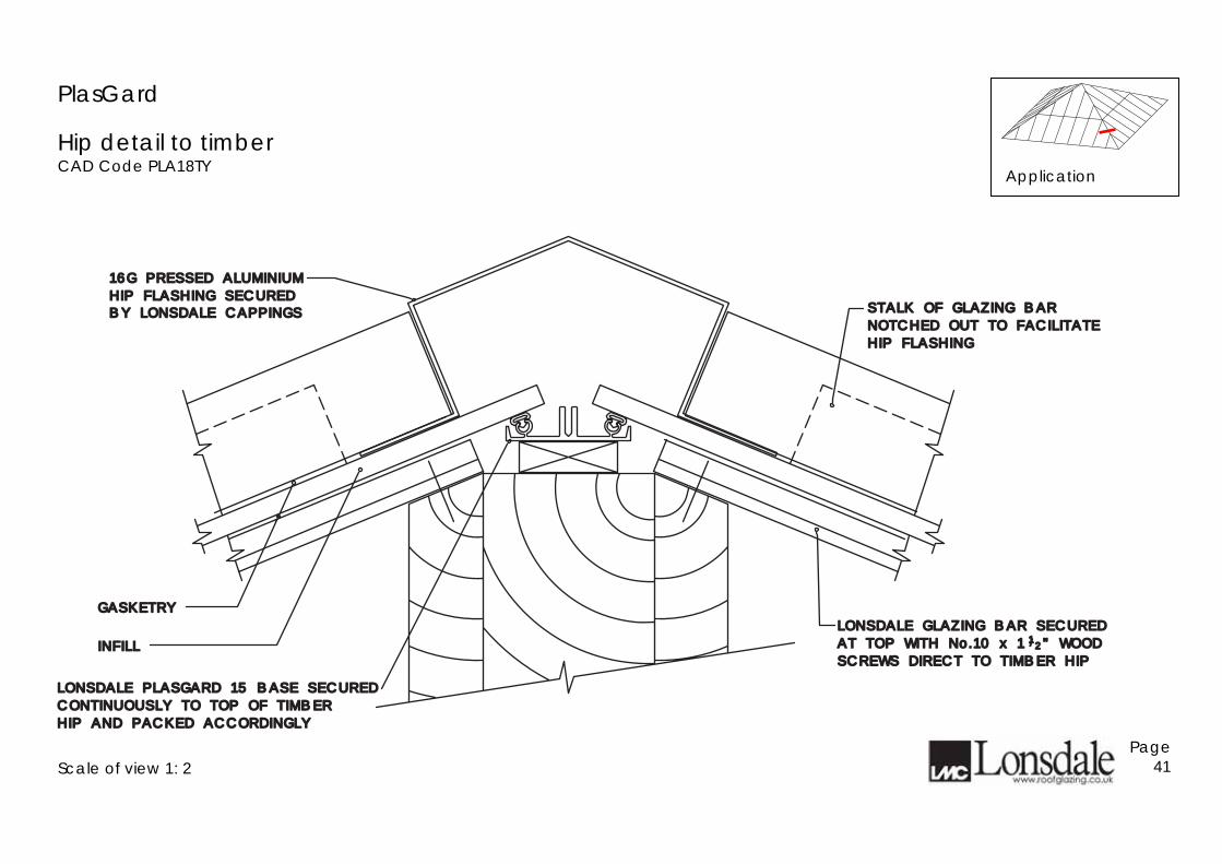
Hip detail to timber CAD Code PLA18TY
Scale of view 1: 2
Page 41
16G PRESSED ALUMINIUM16G PRESSED ALUMINIUM
HIP FLASHING SECUREDHIP FLASHING SECURED
GASKETRYGASKETRY
STALK OF GLAZING BARSTALK OF GLAZING BAR
NOTCHED OUT TO FACILITATENOTCHED OUT TO FACILITATE
HIP FLASHINGHIP FLASHING
LONSDALE GLAZING BAR SECUREDLONSDALE GLAZING BAR SECURED
AT TOP WITH No.10 x 1 " WOODAT TOP WITH No.10 x 1 " WOOD
SCREWS DIRECT TO TIMBER HIPSCREWS DIRECT TO TIMBER HIP
LONSDALE PLASGARD 15 BASE SECUREDLONSDALE PLASGARD 15 BASE SECURED
CONTINUOUSLY TO TOP OF TIMBERCONTINUOUSLY TO TOP OF TIMBER
HIP AND PACKED ACCORDINGLYHIP AND PACKED ACCORDINGLY
11//22
BY LONSDALE CAPPINGSBY LONSDALE CAPPINGS
INFILLINFILL
Application
PlasGard
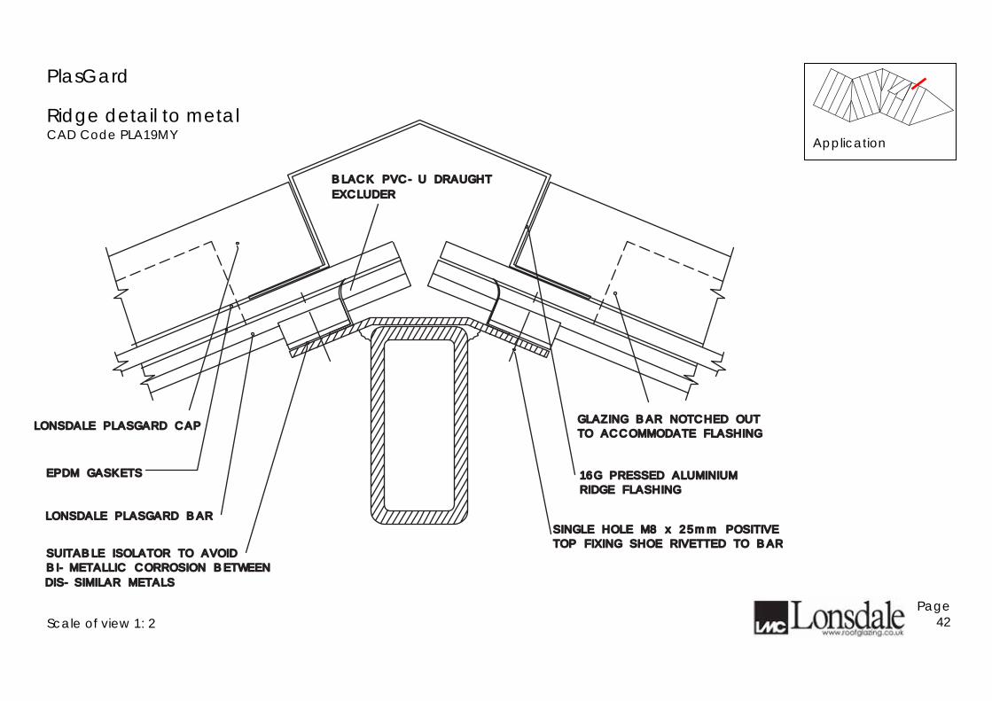
Ridge detail to metal CAD Code PLA19MY
Scale of view 1: 2
Page 42
GLAZING BAR NOTCHED OUTGLAZING BAR NOTCHED OUT
TO ACCOMMODATE FLASHINGTO ACCOMMODATE FLASHING
16G PRESSED ALUMINIUM16G PRESSED ALUMINIUM
RIDGE FLASHINGRIDGE FLASHING
LONSDALE PLASGARD CAPLONSDALE PLASGARD CAP
EPDM GASKETSEPDM GASKETS
LONSDALE PLASGARD BARLONSDALE PLASGARD BAR
TOP FIXING SHOE RIVETTED TO BARTOP FIXING SHOE RIVETTED TO BAR
SINGLE HOLE M8 x 25mm POSITIVESINGLE HOLE M8 x 25mm POSITIVE
BI-METALLIC CORROSION BETWEENBI-METALLIC CORROSION BETWEEN
SUITABLE ISOLATOR TO AVOIDSUITABLE ISOLATOR TO AVOID
DIS-SIMILAR METALSDIS-SIMILAR METALS
EXCLUDEREXCLUDER
BLACK PVC-U DRAUGHT BLACK PVC-U DRAUGHT
Application
PlasGard
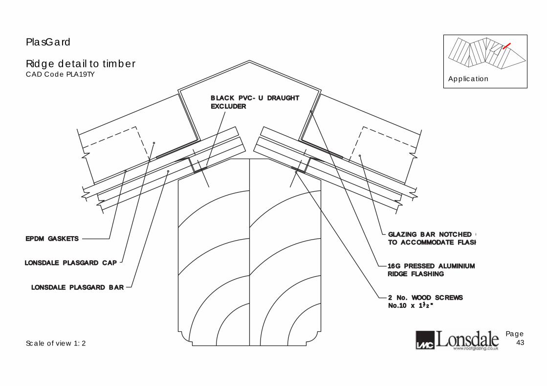
Ridge detail to timber CAD Code PLA19TY
Scale of view 1: 2
Page 43
GLAZING BAR NOTCHED OGLAZING BAR NOTCHED OUT
TO ACCOMMODATE FLASHTO ACCOMMODATE FLASHING
2 No. WOOD SCREWS2 No. WOOD SCREWS
No.10 x 1 "No.10 x 1 "
16G PRESSED ALUMINIUM16G PRESSED ALUMINIUM
RIDGE FLASHINGRIDGE FLASHING
LONSDALE PLASGARD CAPLONSDALE PLASGARD CAP
EPDM GASKETSEPDM GASKETS
LONSDALE PLASGARD BARLONSDALE PLASGARD BAR
11//22
EXCLUDEREXCLUDER
BLACK PVC-U DRAUGHT BLACK PVC-U DRAUGHT
Application
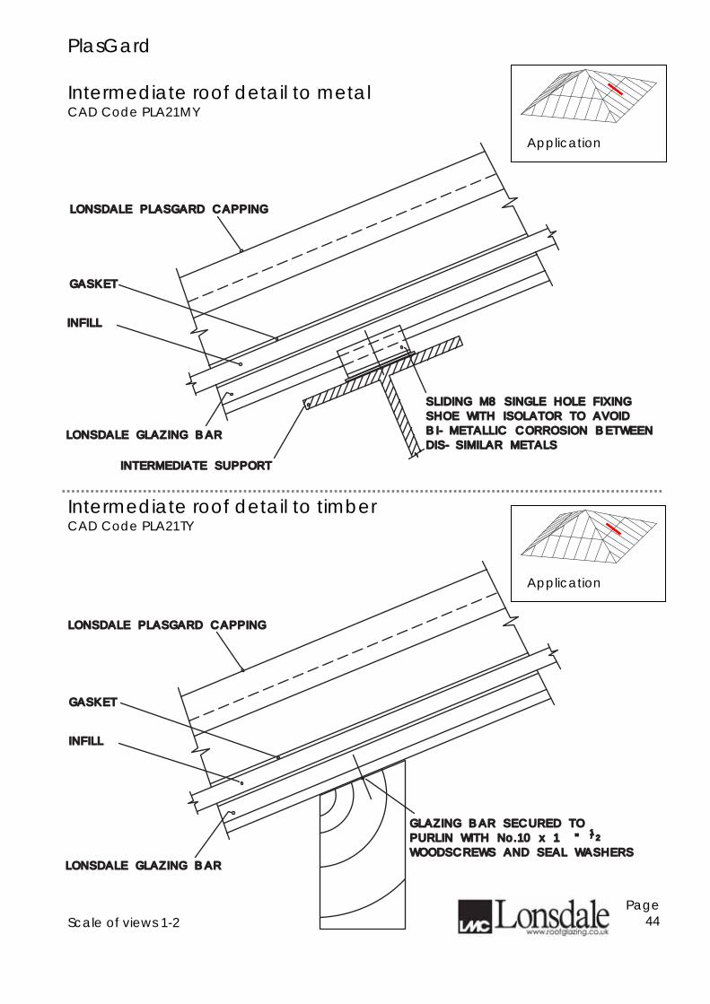
PlasGard Intermediate roof detail to metal CAD Code PLA21MY
Intermediate roof detail to timber CAD Code PLA21TY
Scale of views 1-2
Page 44
LONSDALE PLASGARD CAPPINGLONSDALE PLASGARD CAPPING
LONSDALE GLAZING BARLONSDALE GLAZING BAR
INFILLINFILL
GASKETGASKET
INTERMEDIATE SUPPORTINTERMEDIATE SUPPORT
BI-METALLIC CORROSION BETWEENBI-METALLIC CORROSION BETWEEN
SHOE WITH ISOLATOR TO AVOIDSHOE WITH ISOLATOR TO AVOID
SLIDING M8 SINGLE HOLE FIXINGSLIDING M8 SINGLE HOLE FIXING
DIS-SIMILAR METALSDIS-SIMILAR METALS
LONSDALE PLASGARD CAPPINGLONSDALE PLASGARD CAPPING
GLAZING BAR SECURED TOGLAZING BAR SECURED TO
PURLIN WITH No.10 x 1 " PURLIN WITH No.10 x 1 "
WOODSCREWS AND SEAL WASHERSWOODSCREWS AND SEAL WASHERS
11//22
LONSDALE GLAZING BARLONSDALE GLAZING BAR
INFILLINFILL
GASKETGASKET
Application
Application
PlasGard
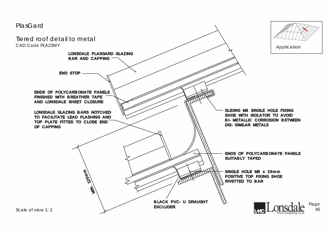
Tiered roof detail to metal CAD Code PLA23MY
Scale of view 1: 2
Page 45
Application
LONSDALE PLASGARD GLAZINGLONSDALE PLASGARD GLAZING
BAR AND CAPPINGBAR AND CAPPING
ENDS OF POLYCARBONATE PANELSENDS OF POLYCARBONATE PANELS
SUITABLY TAPEDSUITABLY TAPED
ENDS OF POLYCARBONATE PANELSENDS OF POLYCARBONATE PANELS
FINISHED WITH BREATHER TAPEFINISHED WITH BREATHER TAPE
AND LONSDALE SHEET CLOSUREAND LONSDALE SHEET CLOSURE
LONSDALE GLAZING BARS NOTCHEDLONSDALE GLAZING BARS NOTCHED
TO FACILITATE LEAD FLASHING ANDTO FACILITATE LEAD FLASHING AND
TOP PLATE FITTED TO CLOSE ENDTOP PLATE FITTED TO CLOSE END
END STOPEND STOP
OF CAPPINGOF CAPPING
SLIDING M8 SINGLE HOLE FIXINGSLIDING M8 SINGLE HOLE FIXING
SHOE WITH ISOLATOR TO AVOIDSHOE WITH ISOLATOR TO AVOID
BI-METALLIC CORROSION BETWEENBI-METALLIC CORROSION BETWEEN
DIS-SIMILAR METALSDIS-SIMILAR METALS
SINGLE HOLE M8 x 25mmSINGLE HOLE M8 x 25mm
POSITIVE TOP FIXING SHOEPOSITIVE TOP FIXING SHOE
MIN. 125mm
MIN. 125mm
RIVETTED TO BARRIVETTED TO BAR
EXCLUDEREXCLUDER
BLACK PVC-U DRAUGHT BLACK PVC-U DRAUGHT
PlasGard
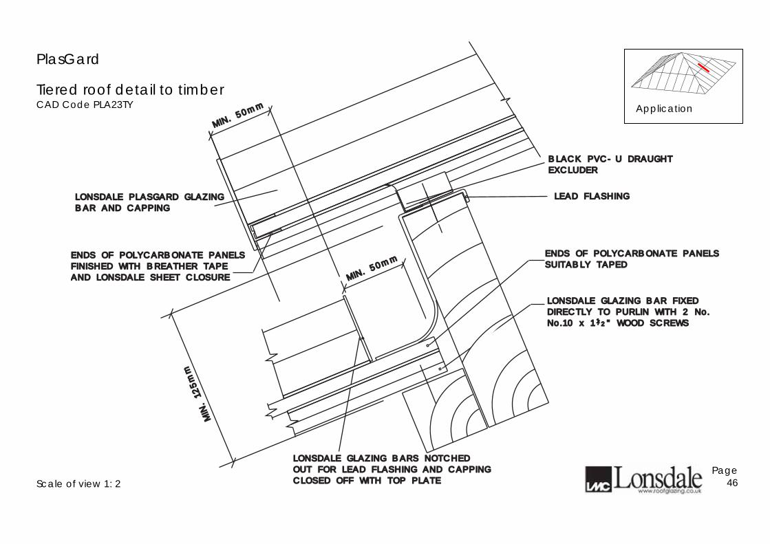
Tiered roof detail to timber CAD Code PLA23TY
Scale of view 1: 2
Page 46
Application
LEAD FLASHINGLEAD FLASHINGLONSDALE PLASGARD GLAZINGLONSDALE PLASGARD GLAZING
BAR AND CAPPINGBAR AND CAPPING
ENDS OF POLYCARBONATE PANELSENDS OF POLYCARBONATE PANELS
SUITABLY TAPEDSUITABLY TAPED
LONSDALE GLAZING BAR FIXEDLONSDALE GLAZING BAR FIXED
DIRECTLY TO PURLIN WITH 2 No.DIRECTLY TO PURLIN WITH 2 No.
No.10 x 1 " WOOD SCREWSNo.10 x 1 " WOOD SCREWS
ENDS OF POLYCARBONATE PANELSENDS OF POLYCARBONATE PANELS
FINISHED WITH BREATHER TAPEFINISHED WITH BREATHER TAPE
AND LONSDALE SHEET CLOSUREAND LONSDALE SHEET CLOSURE
LONSDALE GLAZING BARS NOTCHEDLONSDALE GLAZING BARS NOTCHED
OUT FOR LEAD FLASHING AND CAPPINGOUT FOR LEAD FLASHING AND CAPPING
CLOSED OFF WITH TOP PLATECLOSED OFF WITH TOP PLATE
MIN. 5
0mm
MIN. 5
0mm
MIN. 5
0mm
MIN. 5
0mm
/1 2
MIN. 125mm
MIN. 125mm
BLACK PVC-U DRAUGHTBLACK PVC-U DRAUGHT
EXCLUDEREXCLUDER
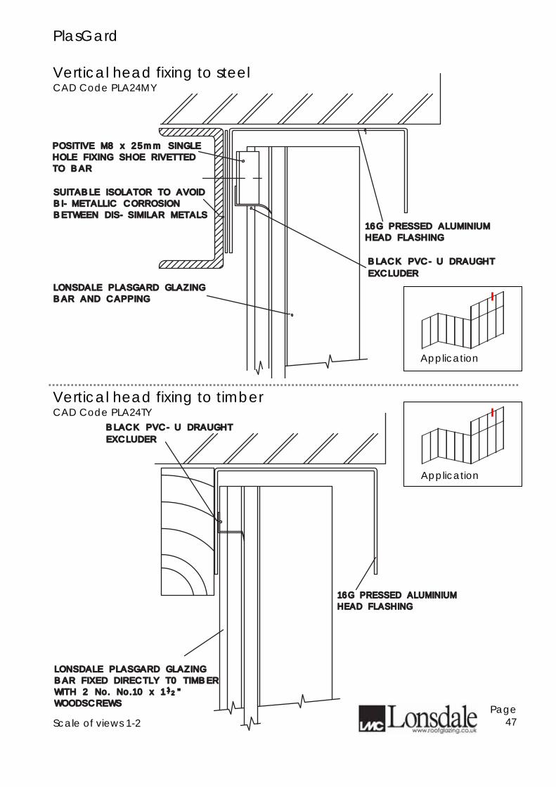
PlasGard Vertical head fixing to steel CAD Code PLA24MY
Vertical head fixing to timber CAD Code PLA24TY
Scale of views 1-2
Page 47
16G PRESSED ALUMINIUM16G PRESSED ALUMINIUM
HEAD FLASHINGHEAD FLASHING
LONSDALE PLASGARD GLAZINGLONSDALE PLASGARD GLAZING
BAR AND CAPPINGBAR AND CAPPING
POSITIVE M8 x 25mm SINGLEPOSITIVE M8 x 25mm SINGLE
HOLE FIXING SHOE RIVETTEDHOLE FIXING SHOE RIVETTED
TO BARTO BAR
SUITABLE ISOLATOR TO AVOIDSUITABLE ISOLATOR TO AVOID
BI-METALLIC CORROSIONBI-METALLIC CORROSION
BETWEEN DIS-SIMILAR METALSBETWEEN DIS-SIMILAR METALS
EXCLUDEREXCLUDER
BLACK PVC-U DRAUGHT BLACK PVC-U DRAUGHT
16G PRESSED ALUMINIUM16G PRESSED ALUMINIUM
HEAD FLASHINGHEAD FLASHING
LONSDALE PLASGARD GLAZINGLONSDALE PLASGARD GLAZING
BAR FIXED DIRECTLY T0 TIMBERBAR FIXED DIRECTLY T0 TIMBER
WITH 2 No. No.10 x 1 "WITH 2 No. No.10 x 1 "
WOODSCREWSWOODSCREWS
11//22
EXCLUDEREXCLUDER
BLACK PVC-U DRAUGHT BLACK PVC-U DRAUGHT
Application
Application
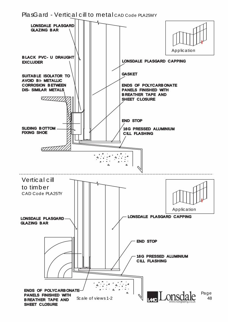
PlasGard - Vertical cill to metal CAD Code PLA25MY
Vertical cill to timber CAD Code PLA25TY
Scale of views 1-2
Page 48
LONSDALE PLASGARD CAPPINGLONSDALE PLASGARD CAPPING
END STOPEND STOP
16G PRESSED ALUMINIUM16G PRESSED ALUMINIUM
CILL FLASHINGCILL FLASHING
LONSDALE PLASGARDLONSDALE PLASGARDGLAZING BARGLAZING BAR
SUITABLE ISOLATOR TOSUITABLE ISOLATOR TO
AVOID BI-METALLICAVOID BI-METALLIC
CORROSION BETWEENCORROSION BETWEEN
DIS-SIMILAR METALSDIS-SIMILAR METALS
ENDS OF POLYCARBONATEENDS OF POLYCARBONATE
PANELS FINISHED WITHPANELS FINISHED WITH
BREATHER TAPE ANDBREATHER TAPE AND
SHEET CLOSURESHEET CLOSURE
GASKETGASKET
FIXING SHOEFIXING SHOESLIDING BOTTOMSLIDING BOTTOM
EXCLUDEREXCLUDER
BLACK PVC-U DRAUGHT BLACK PVC-U DRAUGHT
LONSDALE PLASGARD CAPPINGLONSDALE PLASGARD CAPPING
END STOPEND STOP
16G PRESSED ALUMINIUM16G PRESSED ALUMINIUM
CILL FLASHINGCILL FLASHING
LONSDALE PLASGARDLONSDALE PLASGARD
GLAZING BARGLAZING BAR
ENDS OF POLYCARBONATEENDS OF POLYCARBONATE
PANELS FINISHED WITHPANELS FINISHED WITH
BREATHER TAPE ANDBREATHER TAPE AND
SHEET CLOSURESHEET CLOSURE
Application
Application
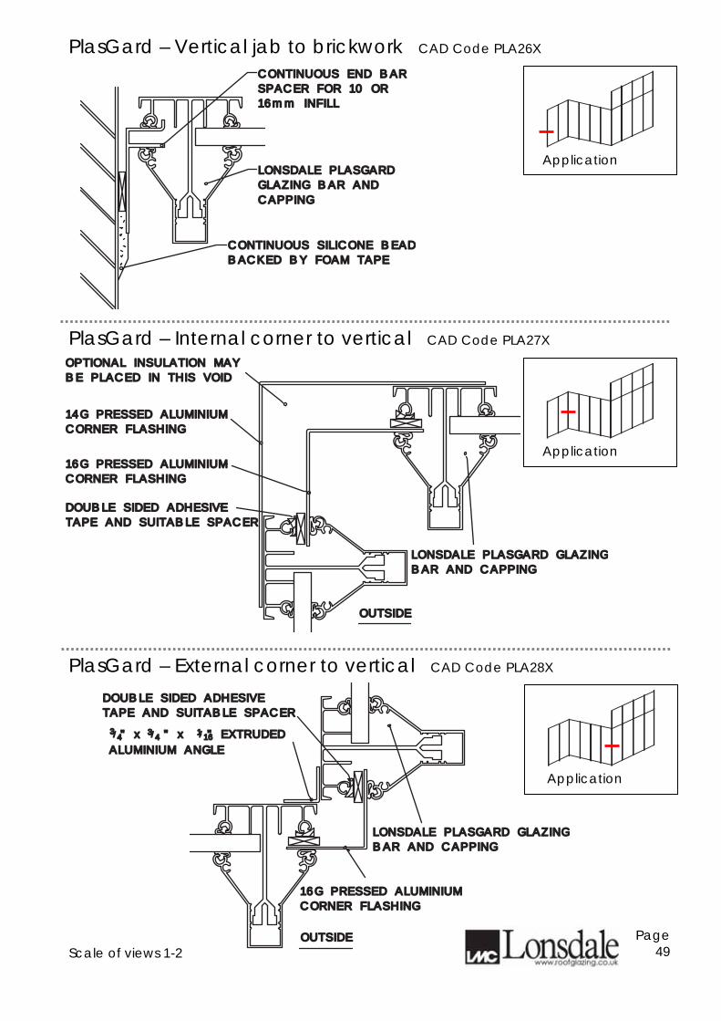
PlasGard – Vertical jab to brickwork CAD Code PLA26X
PlasGard – Internal corner to vertical CAD Code PLA27X
PlasGard – External corner to vertical CAD Code PLA28X
Scale of views 1-2
Page 49
CONTINUOUS END BARCONTINUOUS END BAR
SPACER FOR 10 OR SPACER FOR 10 OR
16mm INFILL16mm INFILL
LONSDALE PLASGARDLONSDALE PLASGARD
GLAZING BAR ANDGLAZING BAR AND
CAPPINGCAPPING
CONTINUOUS SILICONE BEADCONTINUOUS SILICONE BEAD
BACKED BY FOAM TAPEBACKED BY FOAM TAPE
OPTIONAL INSULATION MAYOPTIONAL INSULATION MAY
BE PLACED IN THIS VOIDBE PLACED IN THIS VOID
14G PRESSED ALUMINIUM14G PRESSED ALUMINIUM
CORNER FLASHINGCORNER FLASHING
DOUBLE SIDED ADHESIVEDOUBLE SIDED ADHESIVE
TAPE AND SUITABLE SPACERTAPE AND SUITABLE SPACER
LONSDALE PLASGARD GLAZINGLONSDALE PLASGARD GLAZING
BAR AND CAPPING BAR AND CAPPING
CORNER FLASHINGCORNER FLASHING
16G PRESSED ALUMINIUM16G PRESSED ALUMINIUM
OUTSIDEOUTSIDE
LONSDALE PLASGARD GLAZINGLONSDALE PLASGARD GLAZING
BAR AND CAPPING BAR AND CAPPING
CORNER FLASHINGCORNER FLASHING
16G PRESSED ALUMINIUM16G PRESSED ALUMINIUM
OUTSIDEOUTSIDE
DOUBLE SIDED ADHESIVEDOUBLE SIDED ADHESIVE
TAPE AND SUITABLE SPACERTAPE AND SUITABLE SPACER
33//4411//1616 " x " x " EXTRUDED " x " x " EXTRUDED
ALUMINIUM ANGLEALUMINIUM ANGLE
33//44
Application
Application
Application
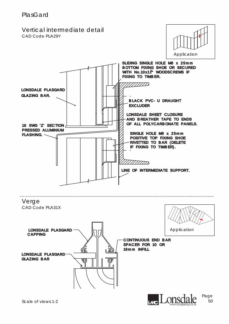
PlasGard Vertical intermediate detail CAD Code PLA29Y
Verge CAD Code PLA31X
Scale of views 1-2
Page 50
SINGLE HOLE M8 x 25mmSINGLE HOLE M8 x 25mm
16 SWG 'Z' SECTION 16 SWG 'Z' SECTION
PRESSED ALUMINIUM PRESSED ALUMINIUM
LONSDALE PLASGARDLONSDALE PLASGARD
GLAZING BAR.GLAZING BAR.
LONSDALE SHEET CLOSURELONSDALE SHEET CLOSURE
AND BREATHER TAPE TO ENDSAND BREATHER TAPE TO ENDS
OF ALL POLYCARBONATE PANELS.OF ALL POLYCARBONATE PANELS.
POSITIVE TOP FIXING SHOEPOSITIVE TOP FIXING SHOE
BOTTOM FIXING SHOE OR SECUREDBOTTOM FIXING SHOE OR SECUREDSLIDING SINGLE HOLE M8 x 25mmSLIDING SINGLE HOLE M8 x 25mm
FLASHING.FLASHING.
RIVETTED TO BAR (DELETERIVETTED TO BAR (DELETE
WITH No.10x1WITH No.10x11122" WOODSCREWS IF" WOODSCREWS IF
FIXING TO TIMBER.FIXING TO TIMBER.
IF FIXING TO TIMBER).IF FIXING TO TIMBER).
LINE OF INTERMEDIATE SUPPORT.LINE OF INTERMEDIATE SUPPORT.
EXCLUDEREXCLUDER
BLACK PVC-U DRAUGHT BLACK PVC-U DRAUGHT
CONTINUOUS END BARCONTINUOUS END BAR
SPACER FOR 10 OR SPACER FOR 10 OR
16mm INFILL16mm INFILL
LONSDALE PLASGARDLONSDALE PLASGARDCAPPINGCAPPING
LONSDALE PLASGARDLONSDALE PLASGARD
GLAZING BARGLAZING BAR
Application
Application
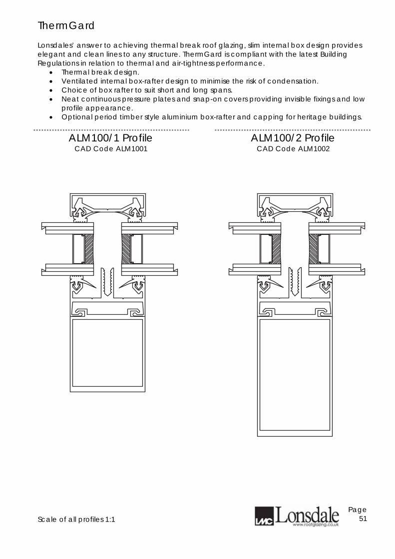
ThermGard Lonsdales’ answer to achieving thermal break roof glazing, slim internal box design provides elegant and clean lines to any structure. ThermGard is compliant with the latest Building Regulations in relation to thermal and air-tightness performance.
• Thermal break design. • Ventilated internal box-rafter design to minimise the risk of condensation. • Choice of box rafter to suit short and long spans. • Neat continuous pressure plates and snap-on covers providing invisible fixings and low
profile appearance. • Optional period timber style aluminium box-rafter and capping for heritage buildings.
ALM100/1 Profile
CAD Code ALM1001 ALM100/2 Profile
CAD Code ALM1002 Scale of all profiles 1:1
Page 51
ThermGard
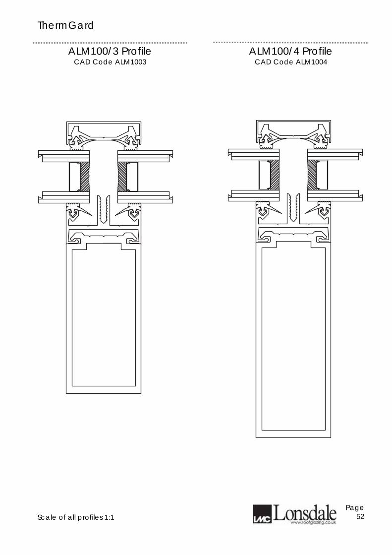
ALM100/3 Profile CAD Code ALM1003
ALM100/4 Profile CAD Code ALM1004
Scale of all profiles 1:1
Page 52
ThermGard
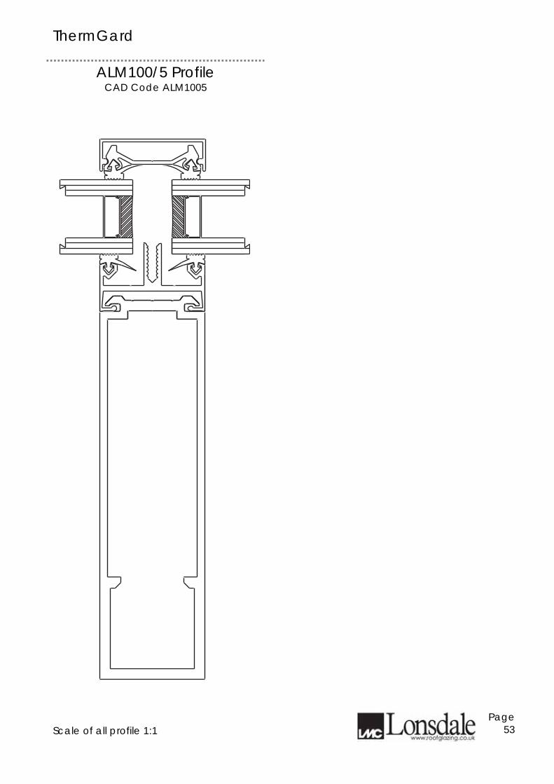
ALM100/5 Profile CAD Code ALM1005
Scale of all profile 1:1
Page 53
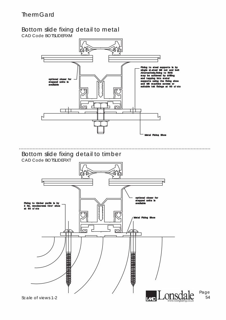
ThermGard Bottom slide fixing detail to metal CAD Code BOTSLIDEFIXM
Bottom slide fixing detail to timber CAD Code BOTSLIDEFIXT
Scale of views 1-2
Page 54
Fixing to steel supports is byFixing to steel supports is by
single st.steel M8 nut and boltsingle st.steel M8 nut and bolt
Alternatively,fixing to RHS Alternatively,fixing to RHS
may be achieved by drillingmay be achieved by drilling
and tapping into metaland tapping into metal
supports using the fixing shoesupports using the fixing shoe
and M6 machine screws orand M6 machine screws or
suitable tek fixings at 60 c/ctssuitable tek fixings at 60 c/cts
optional closer foroptional closer for
stepped units isstepped units is
availableavailable
Metal Fixing ShoeMetal Fixing Shoe
Fixing to timber purlin is byFixing to timber purlin is by
2 No. woodscrews thro' shoe2 No. woodscrews thro' shoe
at 60 c/ctsat 60 c/cts
optional closer foroptional closer for
stepped units isstepped units is
availableavailable
Metal Fixing ShoeMetal Fixing Shoe
ThermGard
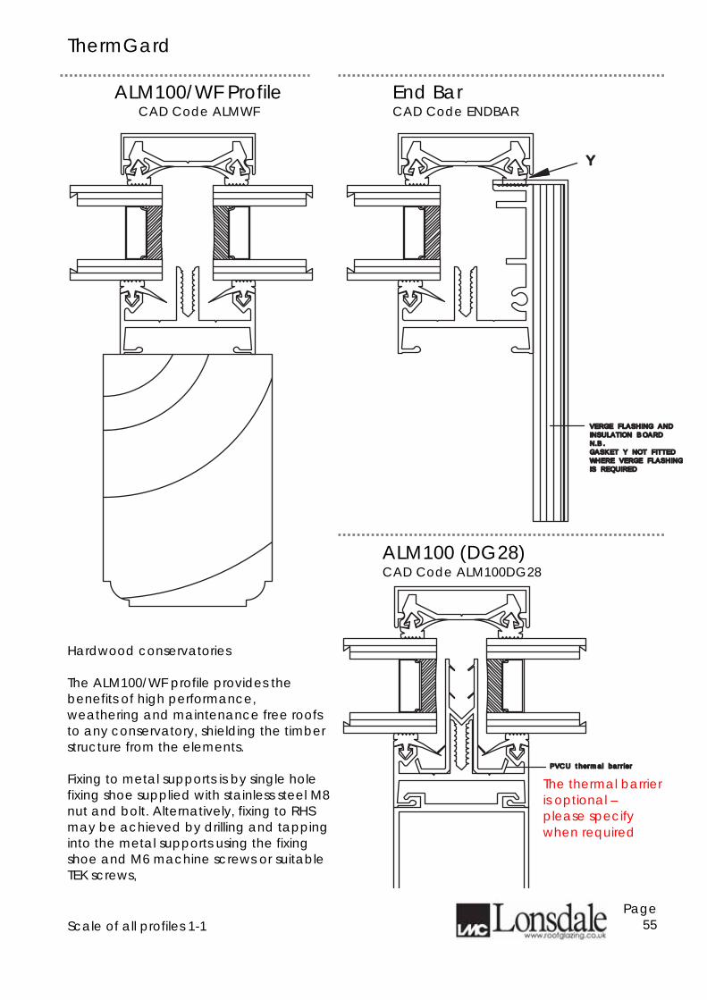
ALM100/WF Profile CAD Code ALMWF
End Bar CAD Code ENDBAR
Hardwood conservatories The ALM100/WF profile provides the benefits of high performance, weathering and maintenance free roofs to any conservatory, shielding the timber structure from the elements. Fixing to metal supports is by single hole fixing shoe supplied with stainless steel M8 nut and bolt. Alternatively, fixing to RHS may be achieved by drilling and tapping into the metal supports using the fixing shoe and M6 machine screws or suitable TEK screws,
Scale of all profiles 1-1
Page 55
YY
VERGE FLASHING AND VERGE FLASHING AND
INSULATION BOARDINSULATION BOARD
N.B.N.B.
GASKET Y NOT FITTEDGASKET Y NOT FITTED
WHERE VERGE FLASHINGWHERE VERGE FLASHING
IS REQUIREDIS REQUIRED
PVCU thermal barrierPVCU thermal barrier
ALM100 (DG28) CAD Code ALM100DG28
The thermal barrier is optional – please specify when required
ThermGard
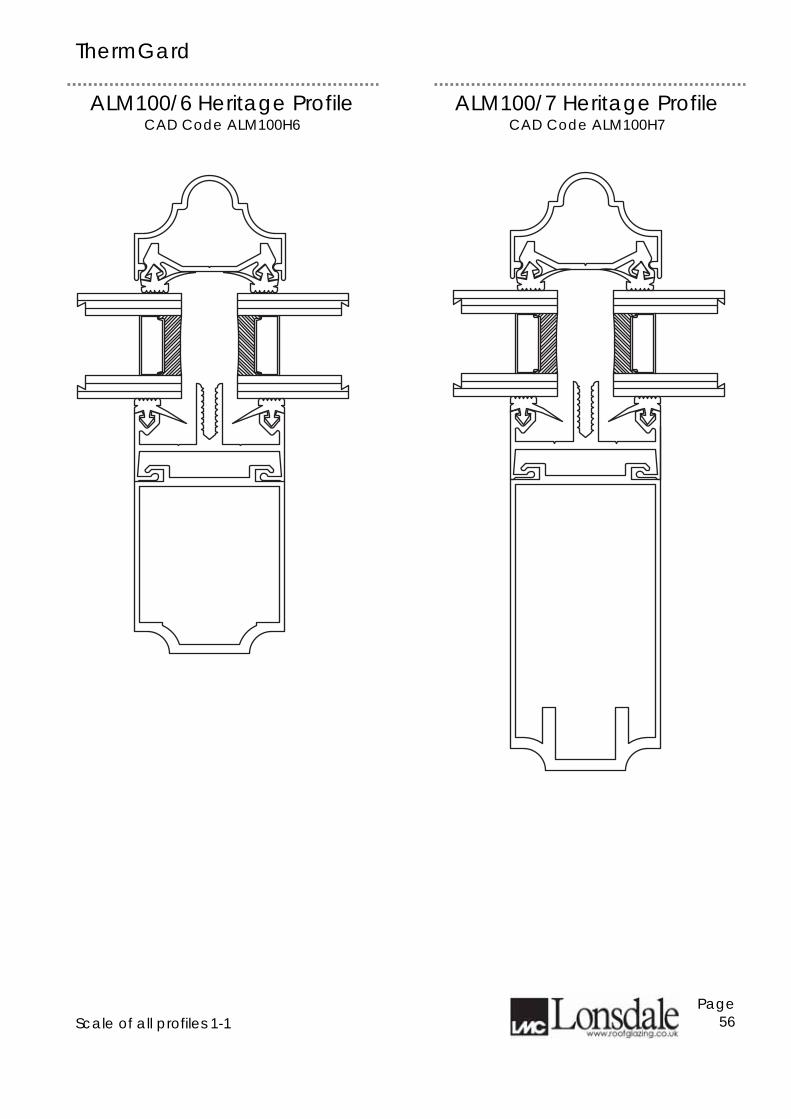
ALM100/6 Heritage Profile CAD Code ALM100H6
ALM100/7 Heritage Profile CAD Code ALM100H7
Scale of all profiles 1-1
Page 56
ThermGard
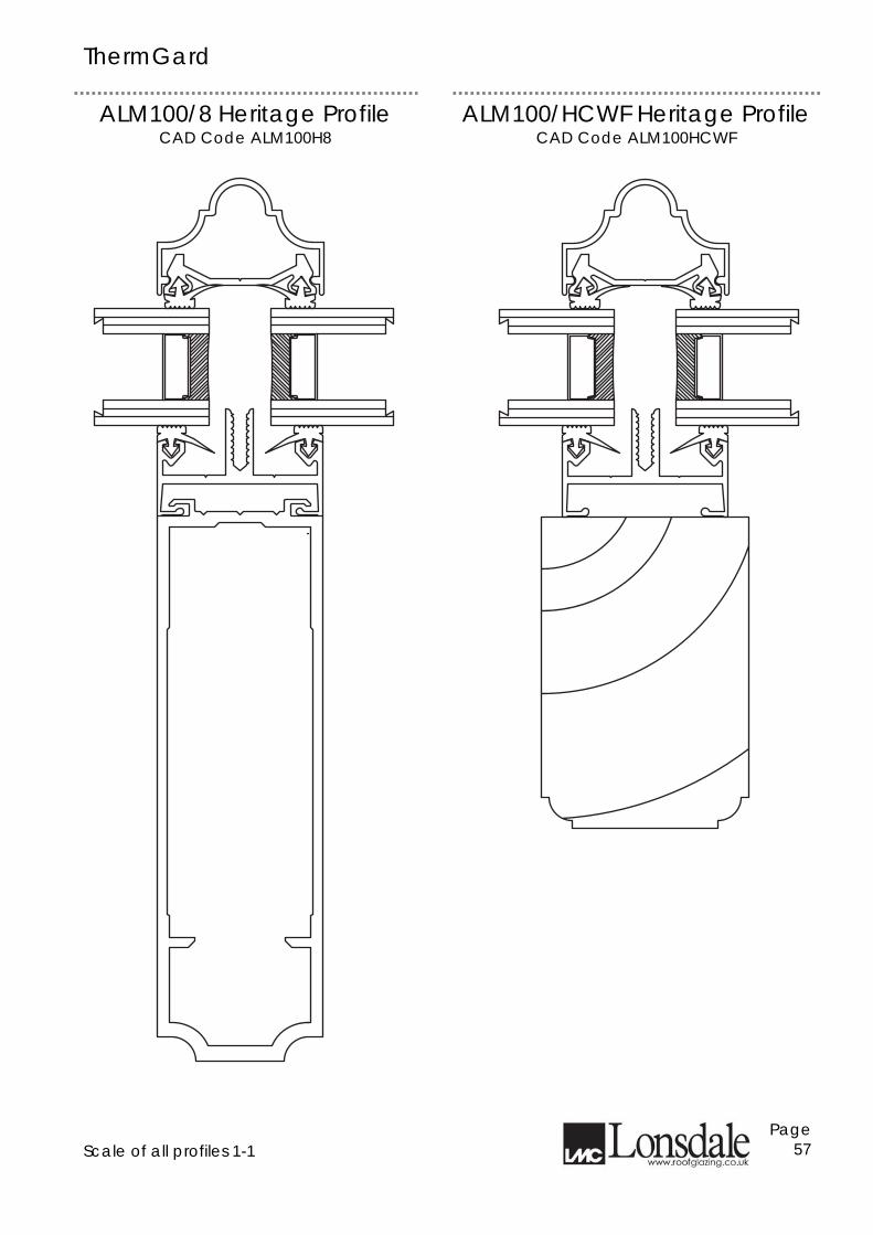
ALM100/8 Heritage Profile CAD Code ALM100H8
ALM100/HCWF Heritage Profile CAD Code ALM100HCWF
Scale of all profiles 1-1
Page 57
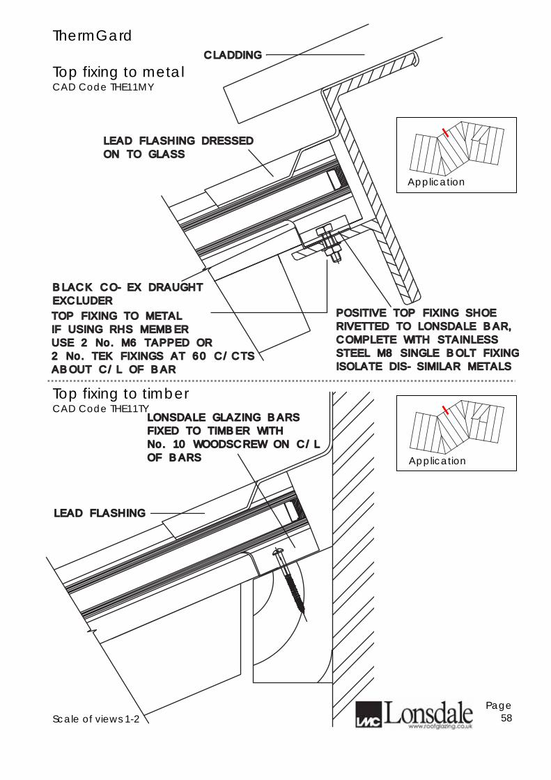
ThermGard Top fixing to metal CAD Code THE11MY
Top fixing to timber CAD Code THE11TY
Scale of views 1-2
Page 58
LEAD FLASHINGLEAD FLASHING
LONSDALE GLAZING BARSLONSDALE GLAZING BARS
FIXED TO TIMBER WITH FIXED TO TIMBER WITH
No. 10 WOODSCREW ON C/LNo. 10 WOODSCREW ON C/L
OF BARSOF BARS
CLADDINGCLADDING
POSITIVE TOP FIXING SHOEPOSITIVE TOP FIXING SHOE
RIVETTED TO LONSDALE BAR,RIVETTED TO LONSDALE BAR,
COMPLETE WITH STAINLESS COMPLETE WITH STAINLESS
STEEL M8 SINGLE BOLT FIXINGSTEEL M8 SINGLE BOLT FIXING
ISOLATE DIS-SIMILAR METALSISOLATE DIS-SIMILAR METALS
TOP FIXING TO METALTOP FIXING TO METAL
IF USING RHS MEMBERIF USING RHS MEMBER
USE 2 No. M6 TAPPED ORUSE 2 No. M6 TAPPED OR
2 No. TEK FIXINGS AT 60 C/CTS2 No. TEK FIXINGS AT 60 C/CTS
ABOUT C/L OF BARABOUT C/L OF BAR
LEAD FLASHING DRESSEDLEAD FLASHING DRESSED
ON TO GLASSON TO GLASS
BLACK CO-EX DRAUGHTBLACK CO-EX DRAUGHT
EXCLUDEREXCLUDER
Application
Application
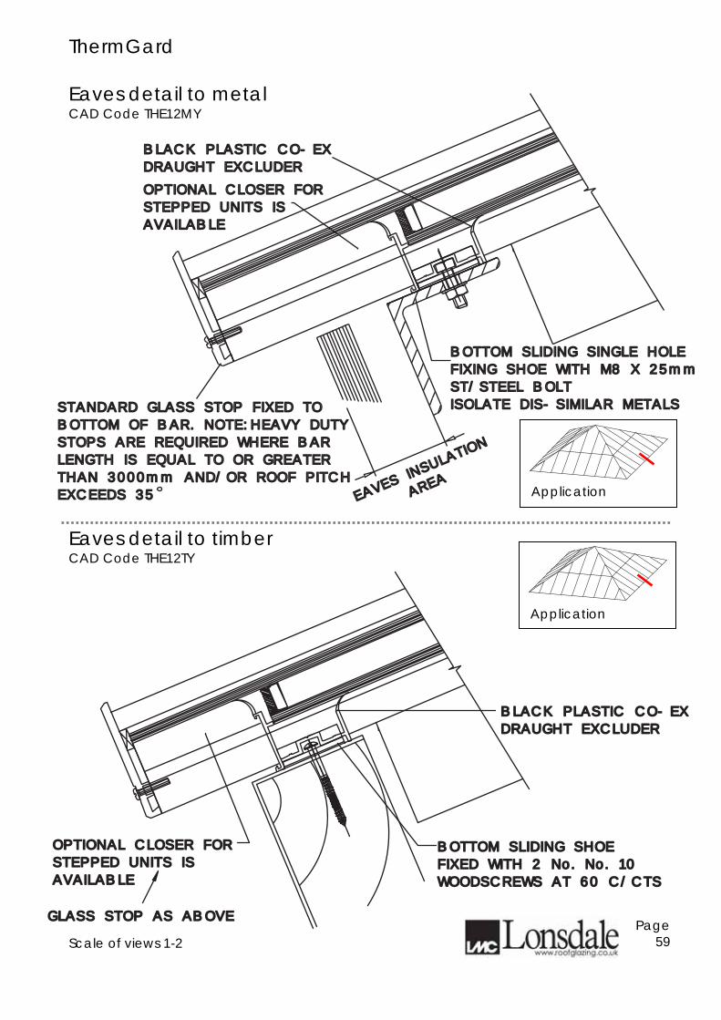
ThermGard Eaves detail to metal CAD Code THE12MY
Eaves detail to timber CAD Code THE12TY
Scale of views 1-2
Page 59
BOTTOM SLIDING SHOEBOTTOM SLIDING SHOE
FIXED WITH 2 No. No. 10 FIXED WITH 2 No. No. 10
WOODSCREWS AT 60 C/CTSWOODSCREWS AT 60 C/CTS
GLASS STOP AS ABOVEGLASS STOP AS ABOVE
OPTIONAL CLOSER FOROPTIONAL CLOSER FOR
STEPPED UNITS ISSTEPPED UNITS IS
AVAILABLEAVAILABLE
BLACK PLASTIC CO-EXBLACK PLASTIC CO-EX
DRAUGHT EXCLUDERDRAUGHT EXCLUDER
OPTIONAL CLOSER FOROPTIONAL CLOSER FOR
STEPPED UNITS ISSTEPPED UNITS IS
AVAILABLEAVAILABLE
BLACK PLASTIC CO-EXBLACK PLASTIC CO-EX
DRAUGHT EXCLUDERDRAUGHT EXCLUDER
BOTTOM SLIDING SINGLE HOLEBOTTOM SLIDING SINGLE HOLE
FIXING SHOE WITH M8 X 25mmFIXING SHOE WITH M8 X 25mm
ST/STEEL BOLTST/STEEL BOLT
ISOLATE DIS-SIMILAR METALSISOLATE DIS-SIMILAR METALSSTANDARD GLASS STOP FIXED TO STANDARD GLASS STOP FIXED TO
BOTTOM OF BAR. NOTE:HEAVY DUTYBOTTOM OF BAR. NOTE:HEAVY DUTY
STOPS ARE REQUIRED WHERE BARSTOPS ARE REQUIRED WHERE BAR
LENGTH IS EQUAL TO OR GREATERLENGTH IS EQUAL TO OR GREATER
THAN 3000mm AND/OR ROOF PITCHTHAN 3000mm AND/OR ROOF PITCH
EXCEEDS 35EXCEEDS 35 EAVES INS
ULATION
EAVES INS
ULATION
AREA
AREA
Application
Application
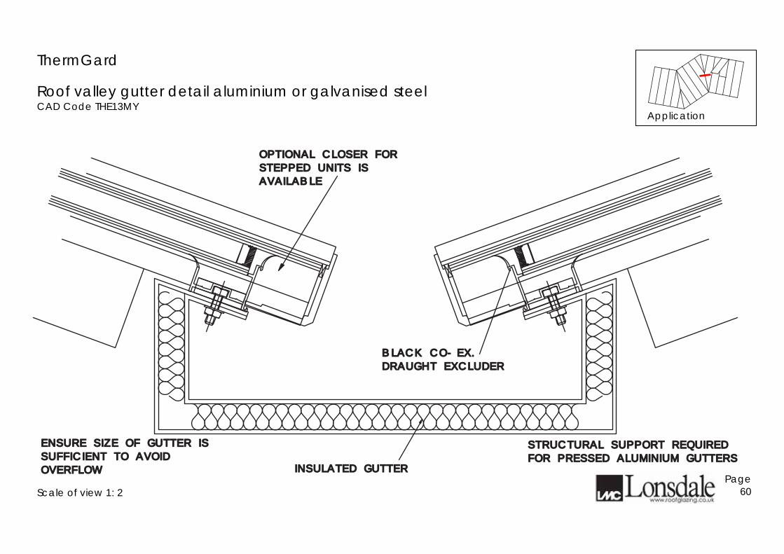
ThermGard
Roof valley gutter detail aluminium or galvanised steel CAD Code THE13MY
Scale of view 1: 2
Page 60
STRUCTURAL SUPPORT REQUIREDSTRUCTURAL SUPPORT REQUIRED
FOR PRESSED ALUMINIUM GUTTERSFOR PRESSED ALUMINIUM GUTTERS
ENSURE SIZE OF GUTTER ISENSURE SIZE OF GUTTER IS
SUFFICIENT TO AVOIDSUFFICIENT TO AVOID
OVERFLOWOVERFLOW INSULATED GUTTERINSULATED GUTTER
BLACK CO-EX.BLACK CO-EX.
DRAUGHT EXCLUDERDRAUGHT EXCLUDER
OPTIONAL CLOSER FOR OPTIONAL CLOSER FOR
STEPPED UNITS ISSTEPPED UNITS IS
AVAILABLEAVAILABLE
Application
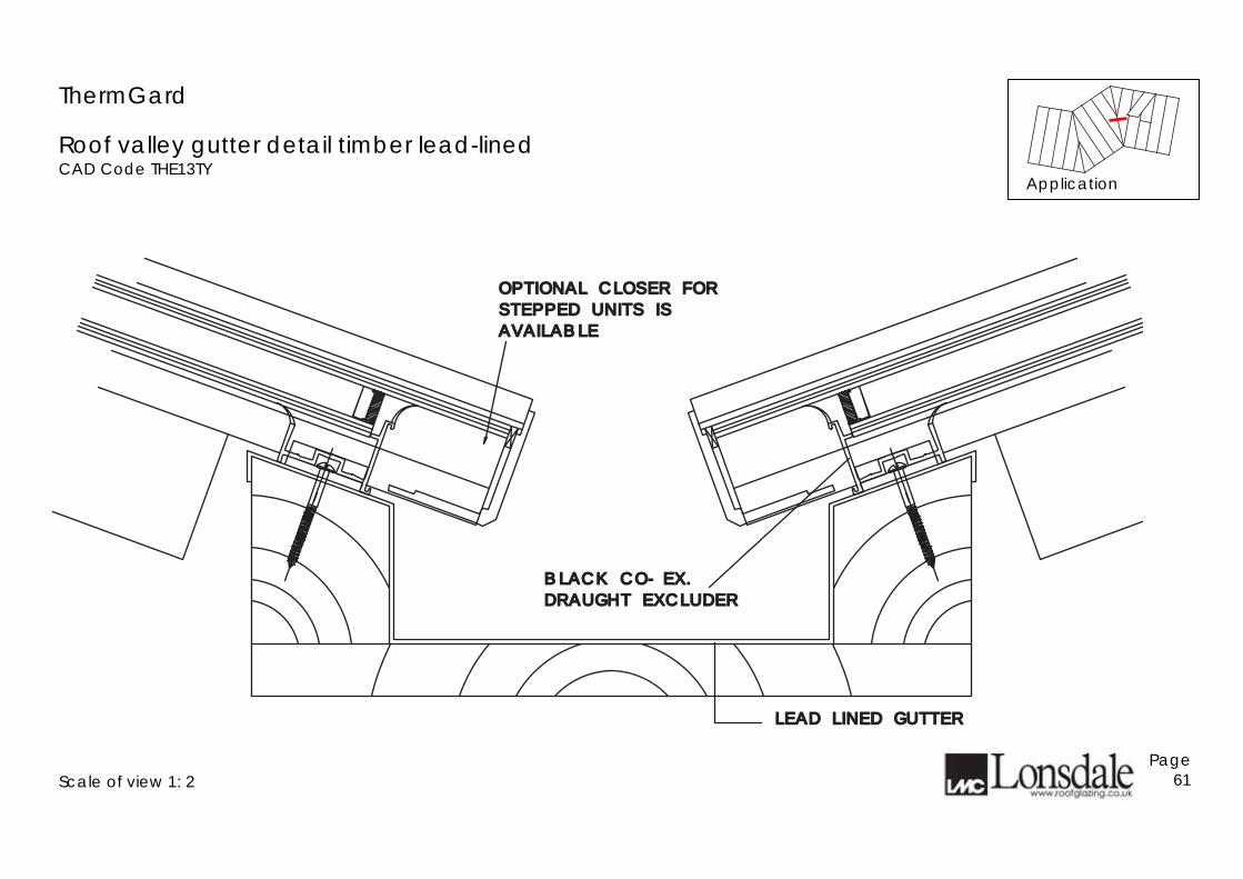
ThermGard
Roof valley gutter detail timber lead-lined CAD Code THE13TY
Scale of view 1: 2
Page 61
BLACK CO-EX.BLACK CO-EX.
DRAUGHT EXCLUDERDRAUGHT EXCLUDER
OPTIONAL CLOSER FOR OPTIONAL CLOSER FOR
STEPPED UNITS ISSTEPPED UNITS IS
AVAILABLEAVAILABLE
LEAD LINED GUTTERLEAD LINED GUTTER
Application
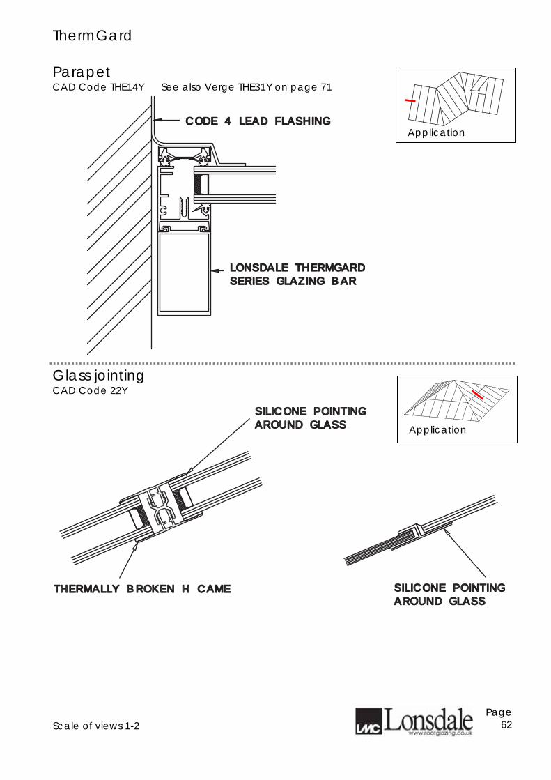
ThermGard Parapet CAD Code THE14Y See also Verge THE31Y on page 71
Glass jointing CAD Code 22Y
Scale of views 1-2
Page 62
LONSDALE THERMGARDLONSDALE THERMGARD
SERIES GLAZING BARSERIES GLAZING BAR
CODE 4 LEAD FLASHINGCODE 4 LEAD FLASHING
SILICONE POINTINGSILICONE POINTING
AROUND GLASSAROUND GLASS
THERMALLY BROKEN H CAMETHERMALLY BROKEN H CAME SILICONE POINTINGSILICONE POINTING
AROUND GLASSAROUND GLASS
Application
Application
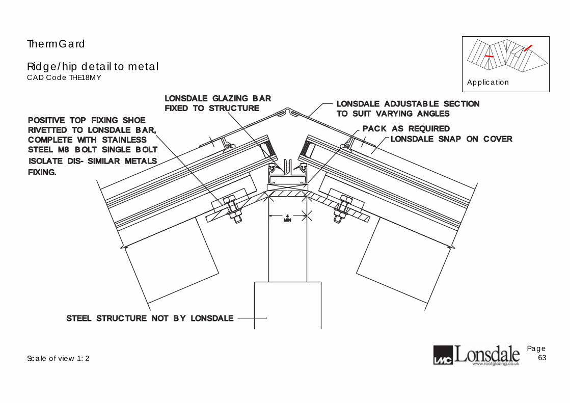
ThermGard
Ridge/hip detail to metal CAD Code THE18MY
Scale of view 1: 2
Page 63
LONSDALE ADJUSTABLE SECTIONLONSDALE ADJUSTABLE SECTION
TO SUIT VARYING ANGLESTO SUIT VARYING ANGLES
LONSDALE SNAP ON COVERLONSDALE SNAP ON COVER
LONSDALE GLAZING BARLONSDALE GLAZING BAR
FIXED TO STRUCTUREFIXED TO STRUCTURE
POSITIVE TOP FIXING SHOEPOSITIVE TOP FIXING SHOE
RIVETTED TO LONSDALE BAR,RIVETTED TO LONSDALE BAR,
COMPLETE WITH STAINLESSCOMPLETE WITH STAINLESS
STEEL M8 BOLT SINGLE BOLTSTEEL M8 BOLT SINGLE BOLT
FIXING.FIXING.
ISOLATE DIS-SIMILAR METALSISOLATE DIS-SIMILAR METALS
PACK AS REQUIREDPACK AS REQUIRED
4MINMIN
STEEL STRUCTURE NOT BY LONSDALESTEEL STRUCTURE NOT BY LONSDALE
Application
ThermGard
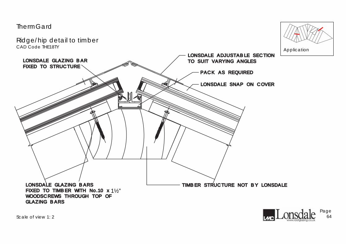
Ridge/hip detail to timber CAD Code THE18TY
Scale of view 1: 2
Page 64
TIMBER STRUCTURE NOT BY LONSDALETIMBER STRUCTURE NOT BY LONSDALE
LONSDALE ADJUSTABLE SECTIONLONSDALE ADJUSTABLE SECTION
TO SUIT VARYING ANGLESTO SUIT VARYING ANGLES
LONSDALE SNAP ON COVERLONSDALE SNAP ON COVER
LONSDALE GLAZING BARLONSDALE GLAZING BAR
FIXED TO STRUCTUREFIXED TO STRUCTURE
PACK AS REQUIREDPACK AS REQUIRED
LONSDALE GLAZING BARSLONSDALE GLAZING BARSFIXED TO TIMBER WITH No.10 x 1FIXED TO TIMBER WITH No.10 x 1
1#1#22 ""
WOODSCREWS THROUGH TOP OFWOODSCREWS THROUGH TOP OFGLAZING BARSGLAZING BARS
Application
1½”
ThermGard
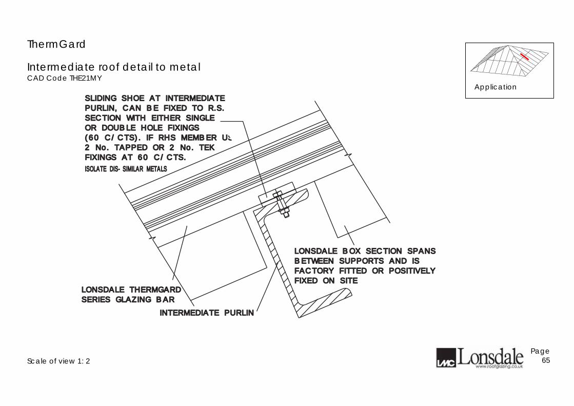
Intermediate roof detail to metal CAD Code THE21MY
Scale of view 1: 2
Page 65
SLIDING SHOE AT INTERMEDIATESLIDING SHOE AT INTERMEDIATE
PURLIN, CAN BE FIXED TO R.S.PURLIN, CAN BE FIXED TO R.S.
SECTION WITH EITHER SINGLESECTION WITH EITHER SINGLE
OR DOUBLE HOLE FIXINGSOR DOUBLE HOLE FIXINGS
(60 C/CTS). IF RHS MEMBER USE(60 C/CTS). IF RHS MEMBER USE
2 No. TAPPED OR 2 No. TEK2 No. TAPPED OR 2 No. TEK
FIXINGS AT 60 C/CTS.FIXINGS AT 60 C/CTS.
ISOLATE DIS-SIMILAR METALSISOLATE DIS-SIMILAR METALS
LONSDALE THERMGARDLONSDALE THERMGARD
SERIES GLAZING BARSERIES GLAZING BAR
INTERMEDIATE PURLININTERMEDIATE PURLIN
LONSDALE BOX SECTION SPANSLONSDALE BOX SECTION SPANS
BETWEEN SUPPORTS AND ISBETWEEN SUPPORTS AND IS
FACTORY FITTED OR POSITIVELYFACTORY FITTED OR POSITIVELY
FIXED ON SITEFIXED ON SITE
Application
ThermGard
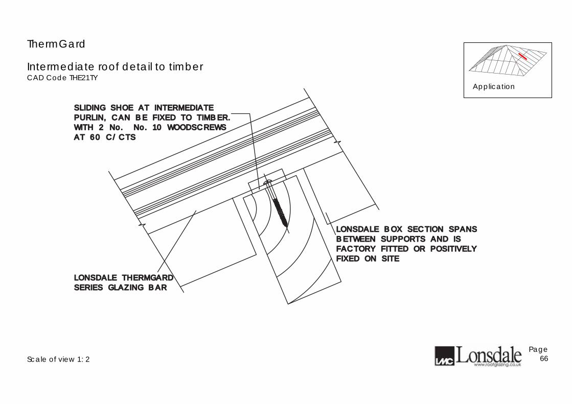
Intermediate roof detail to timber CAD Code THE21TY
Scale of view 1: 2
Page 66
SLIDING SHOE AT INTERMEDIATESLIDING SHOE AT INTERMEDIATE
PURLIN, CAN BE FIXED TO TIMBER.PURLIN, CAN BE FIXED TO TIMBER.
WITH 2 No. No. 10 WOODSCREWS WITH 2 No. No. 10 WOODSCREWS
AT 60 C/CTSAT 60 C/CTS
LONSDALE THERMGARDLONSDALE THERMGARD
SERIES GLAZING BARSERIES GLAZING BAR
LONSDALE BOX SECTION SPANSLONSDALE BOX SECTION SPANS
BETWEEN SUPPORTS AND ISBETWEEN SUPPORTS AND IS
FACTORY FITTED OR POSITIVELYFACTORY FITTED OR POSITIVELY
FIXED ON SITEFIXED ON SITE
Application
ThermGard
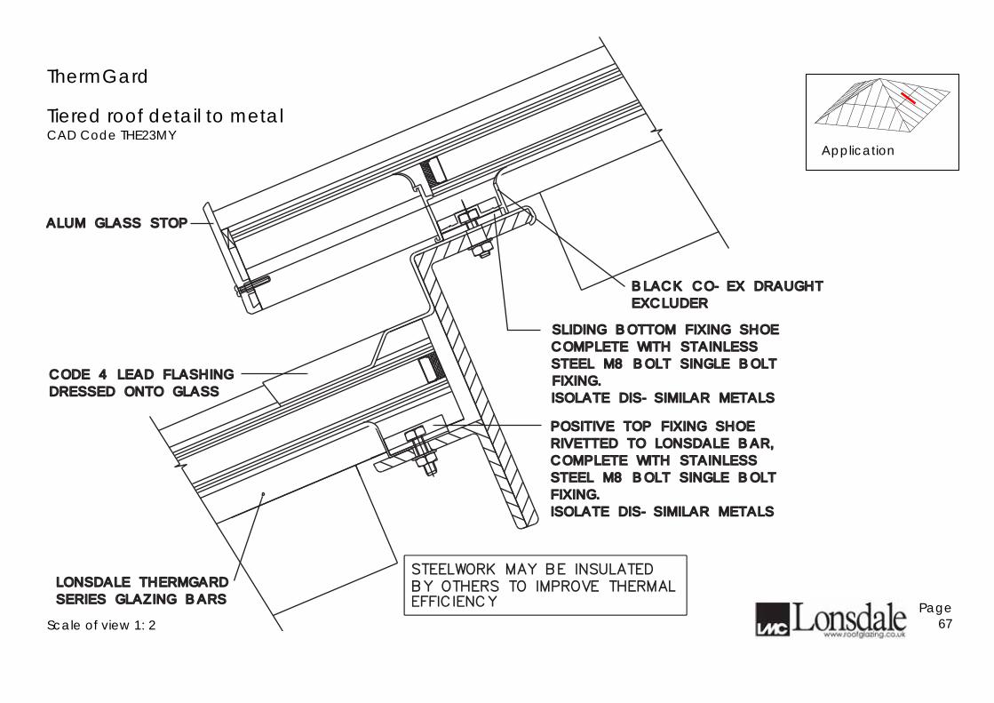
Tiered roof detail to metal CAD Code THE23MY
Scale of view 1: 2
Page 67
POSITIVE TOP FIXING SHOEPOSITIVE TOP FIXING SHOE
RIVETTED TO LONSDALE BAR,RIVETTED TO LONSDALE BAR,
COMPLETE WITH STAINLESSCOMPLETE WITH STAINLESS
STEEL M8 BOLT SINGLE BOLTSTEEL M8 BOLT SINGLE BOLT
FIXING.FIXING.
ISOLATE DIS-SIMILAR METALSISOLATE DIS-SIMILAR METALS
BLACK CO-EX DRAUGHTBLACK CO-EX DRAUGHT
EXCLUDEREXCLUDER
ALUM GLASS STOP ALUM GLASS STOP
CODE 4 LEAD FLASHINGCODE 4 LEAD FLASHING
DRESSED ONTO GLASSDRESSED ONTO GLASS
LONSDALE THERMGARDLONSDALE THERMGARD
SERIES GLAZING BARSSERIES GLAZING BARS
SLIDING BOTTOM FIXING SHOESLIDING BOTTOM FIXING SHOE
COMPLETE WITH STAINLESSCOMPLETE WITH STAINLESS
STEEL M8 BOLT SINGLE BOLTSTEEL M8 BOLT SINGLE BOLT
FIXING.FIXING.
ISOLATE DIS-SIMILAR METALSISOLATE DIS-SIMILAR METALS
EFFICIENCY
STEELWORK MAY BE INSULATED
BY OTHERS TO IMPROVE THERMAL
Application
ThermGard
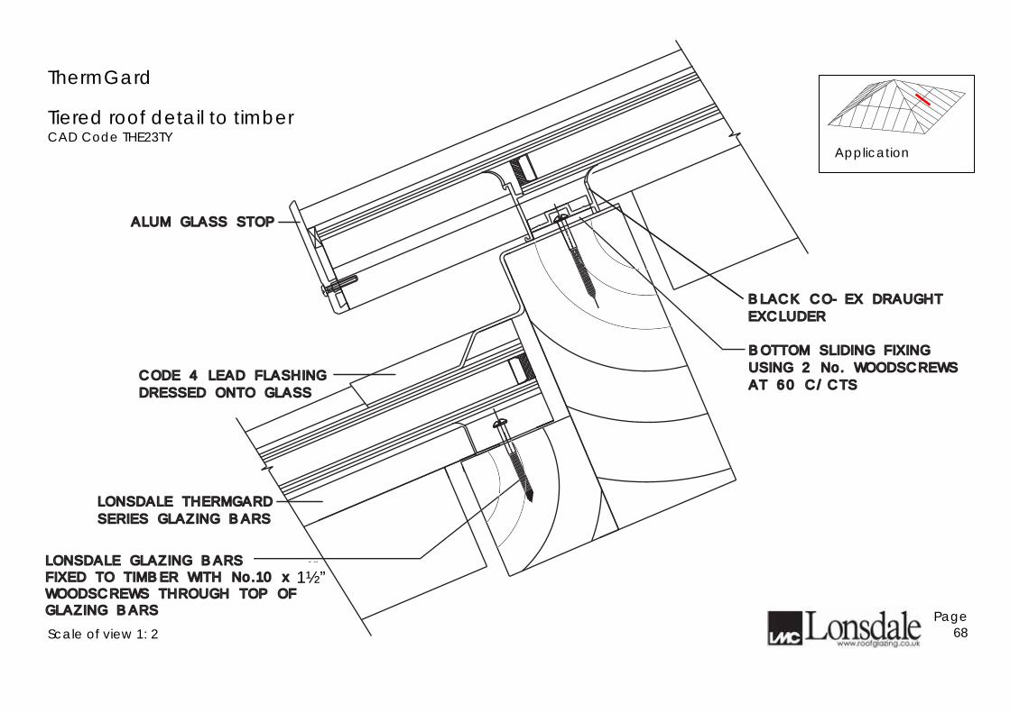
Tiered roof detail to timber CAD Code THE23TY
Scale of view 1: 2
Page 68
BOTTOM SLIDING FIXINGBOTTOM SLIDING FIXING
USING 2 No. WOODSCREWSUSING 2 No. WOODSCREWS
AT 60 C/CTSAT 60 C/CTS
BLACK CO-EX DRAUGHTBLACK CO-EX DRAUGHT
EXCLUDEREXCLUDER
ALUM GLASS STOP ALUM GLASS STOP
CODE 4 LEAD FLASHINGCODE 4 LEAD FLASHING
DRESSED ONTO GLASSDRESSED ONTO GLASS
LONSDALE THERMGARDLONSDALE THERMGARD
SERIES GLAZING BARSSERIES GLAZING BARS
LONSDALE GLAZING BARSFIXED TO TIMBER WITH No.10 x 1
1#2 "
WOODSCREWS THROUGH TOP OFGLAZING BARS
LONSDALE GLAZING BARSFIXED TO TIMBER WITH No.10 x 1
1#2 "
WOODSCREWS THROUGH TOP OFGLAZING BARS
1½”
Application
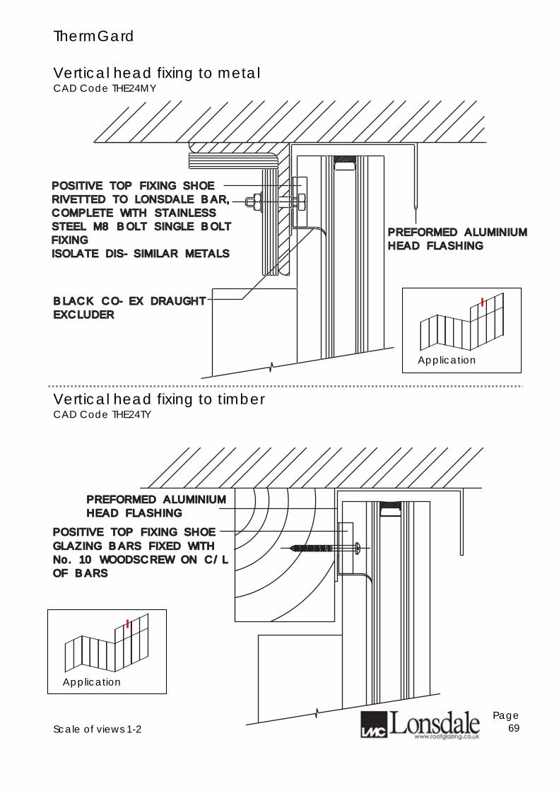
ThermGard Vertical head fixing to metal CAD Code THE24MY
Vertical head fixing to timber CAD Code THE24TY
Scale of views 1-2
Page 69
POSITIVE TOP FIXING SHOEPOSITIVE TOP FIXING SHOE
GLAZING BARS FIXED WITHGLAZING BARS FIXED WITH
No. 10 WOODSCREW ON C/LNo. 10 WOODSCREW ON C/L
OF BARSOF BARS
PREFORMED ALUMINIUMPREFORMED ALUMINIUM
HEAD FLASHINGHEAD FLASHING
PREFORMED ALUMINIUMPREFORMED ALUMINIUM
HEAD FLASHINGHEAD FLASHING
BLACK CO-EX DRAUGHTBLACK CO-EX DRAUGHT
EXCLUDEREXCLUDER
POSITIVE TOP FIXING SHOEPOSITIVE TOP FIXING SHOE
RIVETTED TO LONSDALE BAR,RIVETTED TO LONSDALE BAR,
COMPLETE WITH STAINLESSCOMPLETE WITH STAINLESS
STEEL M8 BOLT SINGLE BOLTSTEEL M8 BOLT SINGLE BOLT
ISOLATE DIS-SIMILAR METALSISOLATE DIS-SIMILAR METALS
FIXINGFIXING
Application
Application
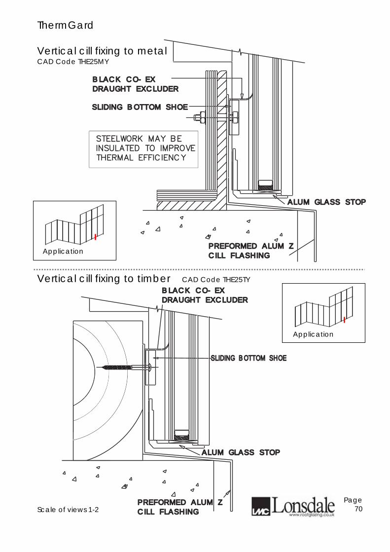
ThermGard Vertical cill fixing to metal CAD Code THE25MY
Vertical cill fixing to timber CAD Code THE25TY
Scale of views 1-2
Page 70
PREFORMED ALUM ZPREFORMED ALUM Z
CILL FLASHINGCILL FLASHING
ALUM GLASS STOPALUM GLASS STOP
SLIDING BOTTOM SHOESLIDING BOTTOM SHOE
THERMAL EFFICIENCY
STEELWORK MAY BE
NSULATED TO IMPROVE
BLACK CO-EXBLACK CO-EX
DRAUGHT EXCLUDERDRAUGHT EXCLUDER
PREFORMED ALUM ZPREFORMED ALUM Z
CILL FLASHINGCILL FLASHING
ALUM GLASS STOPALUM GLASS STOP
SLIDING BOTTOM SHOESLIDING BOTTOM SHOE
BLACK CO-EXBLACK CO-EX
DRAUGHT EXCLUDERDRAUGHT EXCLUDER
Application
Application
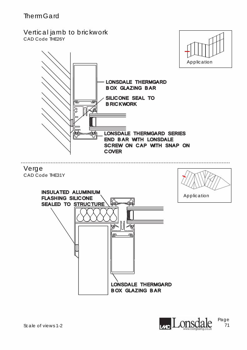
ThermGard Vertical jamb to brickwork CAD Code THE26Y
Verge CAD Code THE31Y
Scale of views 1-2
Page 71
LONSDALE THERMGARDLONSDALE THERMGARD
BOX GLAZING BARBOX GLAZING BAR
LONSDALE THERMGARD SERIESLONSDALE THERMGARD SERIES
END BAR WITH LONSDALEEND BAR WITH LONSDALE
SCREW ON CAP WITH SNAP ONSCREW ON CAP WITH SNAP ON
COVERCOVER
SILICONE SEAL TOSILICONE SEAL TO
BRICKWORKBRICKWORK
LONSDALE THERMGARDLONSDALE THERMGARD
BOX GLAZING BARBOX GLAZING BAR
INSULATED ALUMINIUMINSULATED ALUMINIUM
FLASHING SILICONEFLASHING SILICONE
SEALED TO STRUCTURESEALED TO STRUCTURE
Application
Application
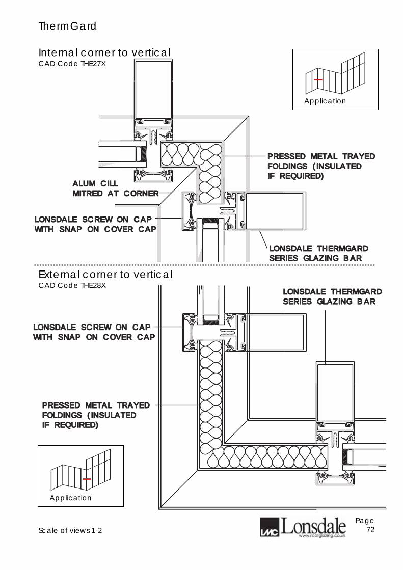
ThermGard Internal corner to vertical CAD Code THE27X
External corner to vertical CAD Code THE28X
Scale of views 1-2
Page 72
LONSDALE THERMGARDLONSDALE THERMGARD
SERIES GLAZING BARSERIES GLAZING BAR
LONSDALE SCREW ON CAPLONSDALE SCREW ON CAP
WITH SNAP ON COVER CAP WITH SNAP ON COVER CAP
ALUM CILLALUM CILL
MITRED AT CORNERMITRED AT CORNER
PRESSED METAL TRAYEDPRESSED METAL TRAYED
FOLDINGS (INSULATEDFOLDINGS (INSULATED
IF REQUIRED)IF REQUIRED)
PRESSED METAL TRAYEDPRESSED METAL TRAYED
FOLDINGS (INSULATEDFOLDINGS (INSULATED
IF REQUIRED)IF REQUIRED)
LONSDALE SCREW ON CAPLONSDALE SCREW ON CAP
WITH SNAP ON COVER CAP WITH SNAP ON COVER CAP
LONSDALE THERMGARDLONSDALE THERMGARD
SERIES GLAZING BARSERIES GLAZING BAR
Application
Application
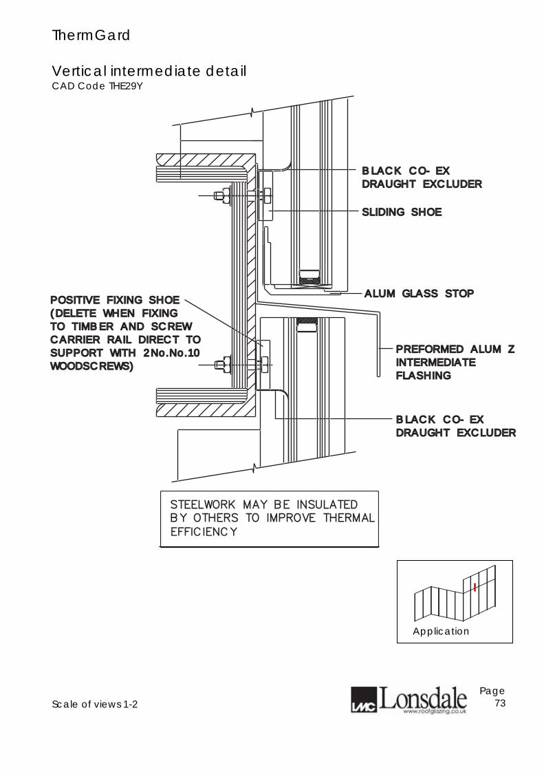
ThermGard Vertical intermediate detail CAD Code THE29Y
Scale of views 1-2
Page 73
SLIDING SHOESLIDING SHOE
BLACK CO-EXBLACK CO-EX
DRAUGHT EXCLUDERDRAUGHT EXCLUDER
ALUM GLASS STOPALUM GLASS STOP
PREFORMED ALUM ZPREFORMED ALUM Z
INTERMEDIATEINTERMEDIATE
FLASHINGFLASHING
BLACK CO-EXBLACK CO-EX
DRAUGHT EXCLUDERDRAUGHT EXCLUDER
POSITIVE FIXING SHOEPOSITIVE FIXING SHOE
(DELETE WHEN FIXING(DELETE WHEN FIXING
TO TIMBER AND SCREWTO TIMBER AND SCREW
CARRIER RAIL DIRECT TOCARRIER RAIL DIRECT TO
SUPPORT WITH 2No.No.10SUPPORT WITH 2No.No.10
WOODSCREWS)WOODSCREWS)
EFFICIENCY
STEELWORK MAY BE INSULATED
BY OTHERS TO IMPROVE THERMAL
Application
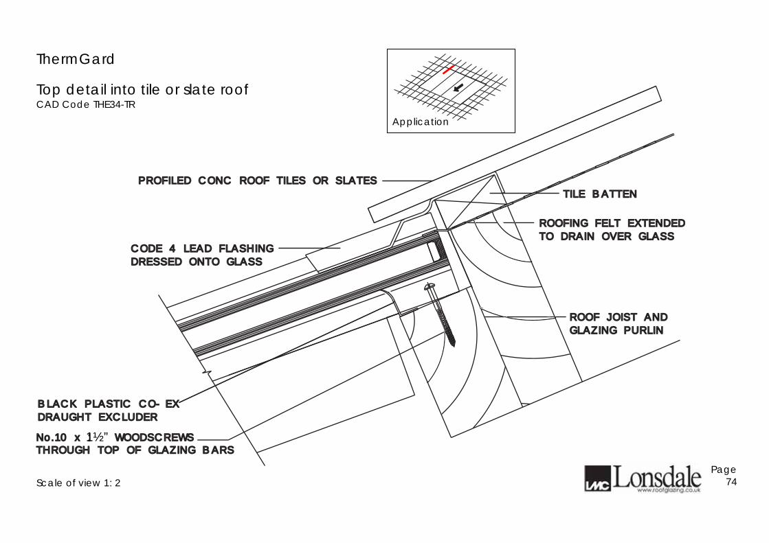
ThermGard
Top detail into tile or slate roof CAD Code THE34-TR
Scale of view 1: 2
Page 74
PROFILED CONC ROOF TILES OR SLATESPROFILED CONC ROOF TILES OR SLATES
TILE BATTENTILE BATTEN
ROOFING FELT EXTENDEDROOFING FELT EXTENDED
TO DRAIN OVER GLASSTO DRAIN OVER GLASS
ROOF JOIST ANDROOF JOIST AND
GLAZING PURLINGLAZING PURLIN
BLACK PLASTIC CO-EXBLACK PLASTIC CO-EX
DRAUGHT EXCLUDERDRAUGHT EXCLUDER
CODE 4 LEAD FLASHINGCODE 4 LEAD FLASHING
DRESSED ONTO GLASSDRESSED ONTO GLASS
No.10 x 11#2 " WOODSCREWS
THROUGH TOP OF GLAZING BARSNo.10 x 1
1#2 " WOODSCREWS
THROUGH TOP OF GLAZING BARS
1½”
Application
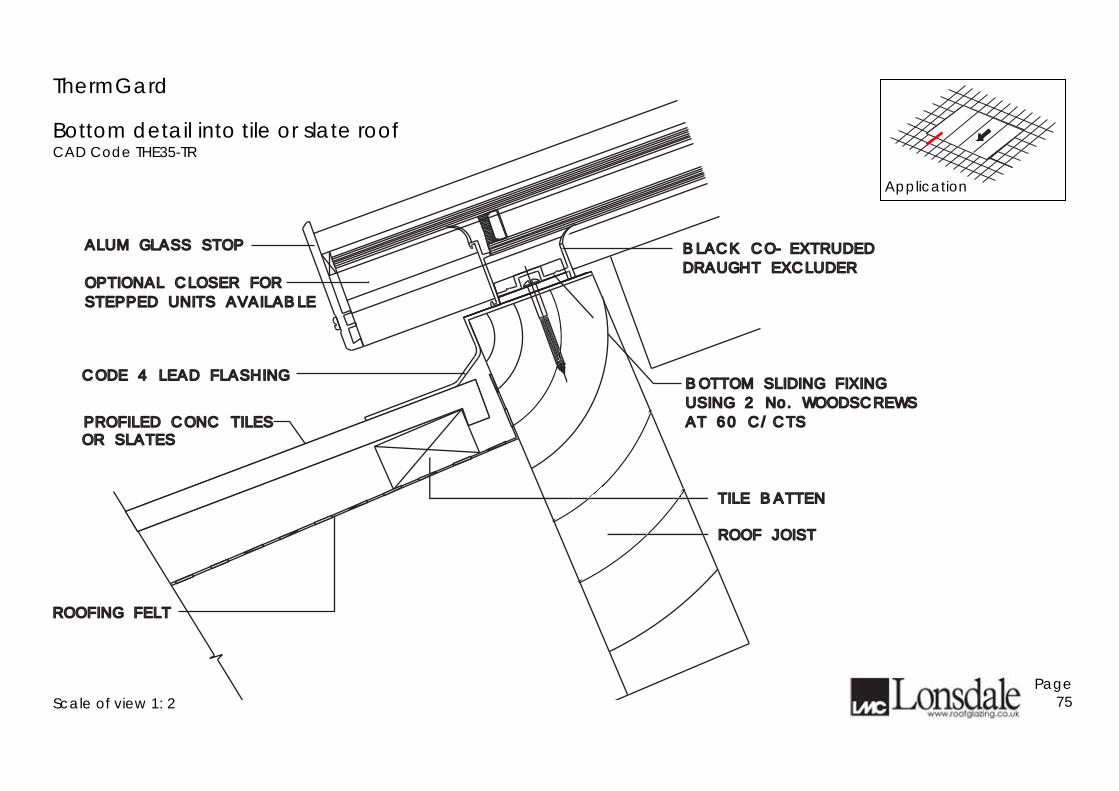
ThermGard
Bottom detail into tile or slate roof CAD Code THE35-TR
Scale of view 1: 2
Page 75
PROFILED CONC TILESPROFILED CONC TILES
TILE BATTENTILE BATTEN
ROOFING FELTROOFING FELT
ROOF JOISTROOF JOIST
CODE 4 LEAD FLASHINGCODE 4 LEAD FLASHING
BLACK CO-EXTRUDEDBLACK CO-EXTRUDED
DRAUGHT EXCLUDERDRAUGHT EXCLUDER
BOTTOM SLIDING FIXINGBOTTOM SLIDING FIXING
USING 2 No. WOODSCREWSUSING 2 No. WOODSCREWS
AT 60 C/CTSAT 60 C/CTSOR SLATESOR SLATES
OPTIONAL CLOSER FOROPTIONAL CLOSER FOR
STEPPED UNITS AVAILABLESTEPPED UNITS AVAILABLE
ALUM GLASS STOP ALUM GLASS STOP
Application
ThermGard
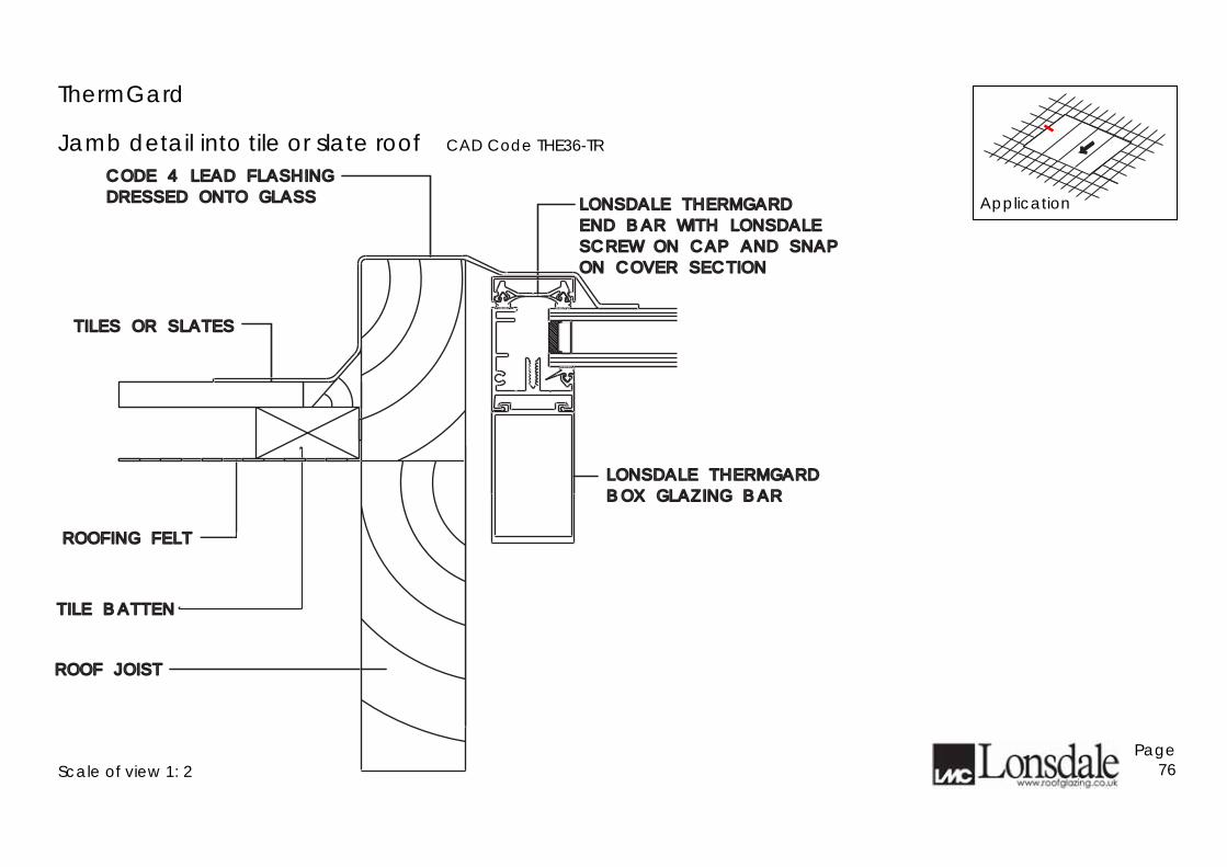
Jamb detail into tile or slate roof CAD Code THE36-TR
Scale of view 1: 2
Page 76
CODE 4 LEAD FLASHINGCODE 4 LEAD FLASHING
DRESSED ONTO GLASSDRESSED ONTO GLASS
LONSDALE THERMGARDLONSDALE THERMGARD
BOX GLAZING BARBOX GLAZING BAR
LONSDALE THERMGARDLONSDALE THERMGARD
END BAR WITH LONSDALEEND BAR WITH LONSDALE
SCREW ON CAP AND SNAPSCREW ON CAP AND SNAP
ON COVER SECTIONON COVER SECTION
ROOFING FELTROOFING FELT
TILE BATTENTILE BATTEN
ROOF JOISTROOF JOIST
TILES OR SLATESTILES OR SLATES
Application

Page 77
ROOF JOIST Scale of view 1: 2
PROFILED CONC TILES OR SLATES
TILTING FILLET LAID TO FALL
ROOF FELT
CODE 4 LEAD FLASHING OVER ROOFING FELT
16g ALUM GUTTER SECTION BEDDED ON SILICONE
ThermGard In-line roof glazing Bottom detail into tile/slate roof CAD Code THE37-TRIL
ALUM GLASS STOP
OPTIONAL CLOSER FOR STEPPED UNITS AVAILABLE
BLACK CO-EXTRUDED DRAUGHT EXCLUDER
BOTTOM SLIDING FIXING USING No 2 WOODSCREWS AT 60mm C/CTS
NOTE: MINIMUM PITCH OF 20° REFER TO LONSDALE TECHNICAL DEPARTMENT FOR PITCHES BELOW 20°
Page 78
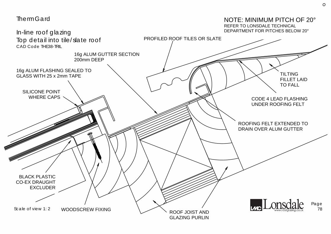
ThermGard In-line roof glazing Top detail into tile/slate roof CAD Code THE38-TRIL
PROFILED ROOF TILES OR SLATE
16g ALUM GUTTER SECTION 200mm DEEP
16g ALUM FLASHING SEALED TO GLASS WITH 25 x 2mm TAPE
SILICONE POINT WHERE CAPS
BLACK PLASTIC CO-EX DRAUGHT
EXCLUDER
Scale of view 1: 2 WOODSCREW FIXING ROOF JOIST AND GLAZING PURLIN
ROOFING FELT EXTENDED TO DRAIN OVER ALUM GUTTER
CODE 4 LEAD FLASHING UNDER ROOFING FELT
TILTING FILLET LAID TO FALL
NOTE: MINIMUM PITCH OF 20° REFER TO LONSDALE TECHNICAL DEPARTMENT FOR PITCHES BELOW 20°
Page 79
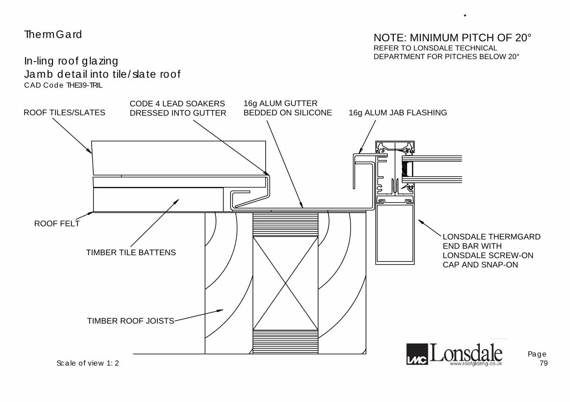
ThermGard In-ling roof glazing Jamb detail into tile/slate roof CAD Code THE39-TRIL
Scale of view 1: 2
CODE 4 LEAD SOAKERS DRESSED INTO GUTTER
16g ALUM GUTTER BEDDED ON SILICONE
16g ALUM JAB FLASHING
16g ALUM GUTTER BEDDED ON SILICONE
LONSDALE THERMGARD END BAR WITH LONSDALE SCREW-ON CAP AND SNAP-ON
TIMBER ROOF JOISTS
TIMBER TILE BATTENS
ROOF FELT
ROOF TILES/SLATES
NOTE: MINIMUM PITCH OF 20° REFER TO LONSDALE TECHNICAL DEPARTMENT FOR PITCHES BELOW 20°
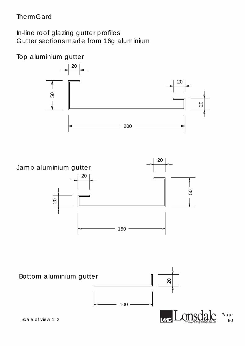
ThermGard In-line roof glazing gutter profiles Gutter sections made from 16g aluminium
20
20
20
50
200
150
20
20
20
50
20
100
Top aluminium gutter
Jamb aluminium gutter
Bottom aluminium gutter
Scale of view 1: 2 Page 80
Page 81
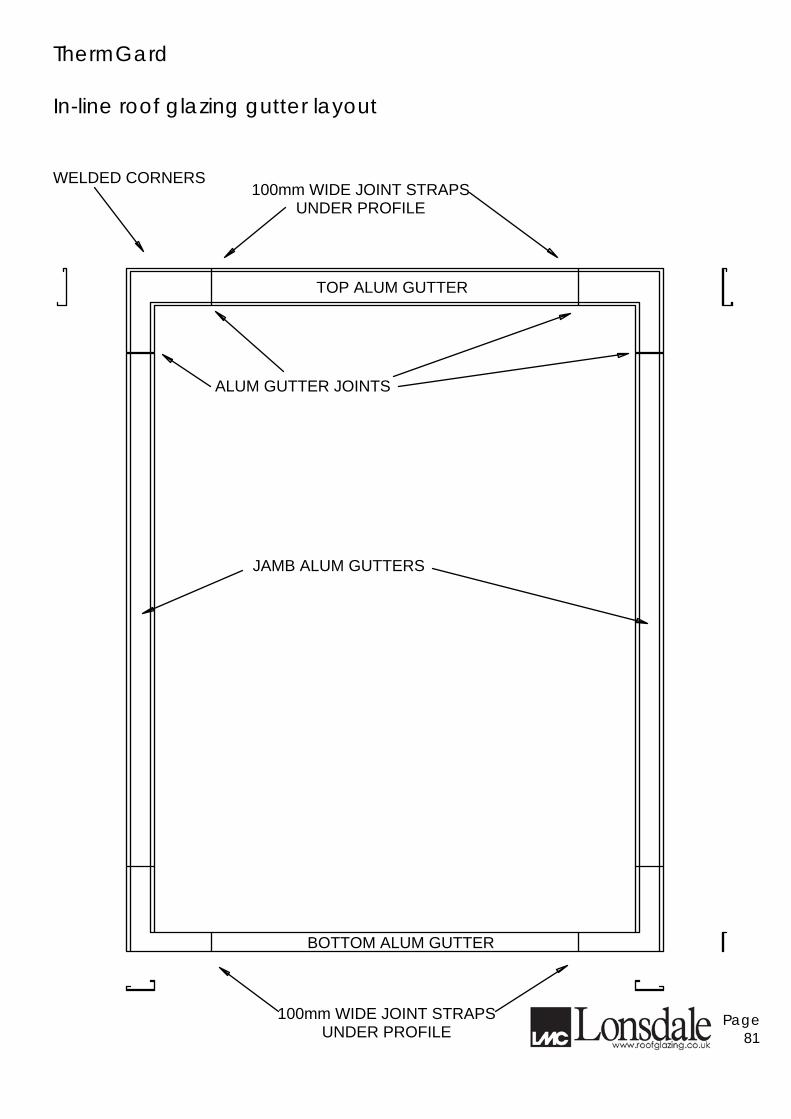
ThermGard In-line roof glazing gutter layout
BOTTOM ALUM GUTTER
100mm WIDE JOINT STRAPS UNDER PROFILE
JAMB ALUM GUTTERS
ALUM GUTTER JOINTS
WELDED CORNERS 100mm WIDE JOINT STRAPS
UNDER PROFILE
TOP ALUM GUTTER
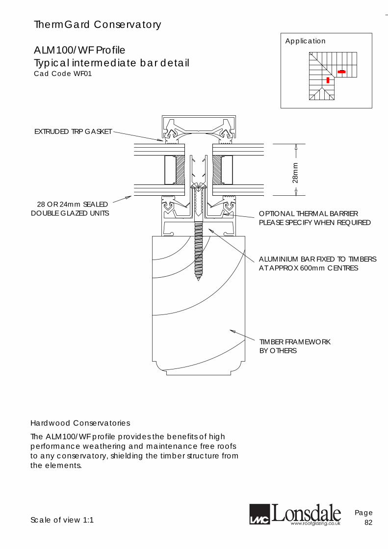
ThermGard Conservatory ALM100/WF Profile Typical intermediate bar detail Cad Code WF01
Application
EXTRUDED TRP GASKET
28 OR 24mm SEALED DOUBLE GLAZED UNITS
28m
m
OPTIONAL THERMAL BARRIER PLEASE SPECIFY WHEN REQUIRED
ALUMINIUM BAR FIXED TO TIMBERS AT APPROX 600mm CENTRES
TIMBER FRAMEWORK BY OTHERS
Hardwood Conservatories
The ALM100/WF profile provides the benefits of high performance weathering and maintenance free roofs to any conservatory, shielding the timber structure from the elements. Scale of view 1:1
Page 82
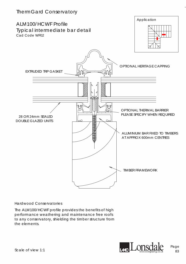
ThermGard Conservatory ALM100/HCWF Profile Typical intermediate bar detail Cad Code WF02
Application
EXTRUDED TRP GASKET
OPTIONAL THERMAL BARRIER PLEASE SPECIFY WHEN REQUIRED
ALUMINIUM BAR FIXED TO TIMBERS AT APPROX 600mm CENTRES
TIMBER FRAMEWORK
OPTIONAL HERITAGE CAPPING
28 OR 24mm SEALED DOUBLE GLAZED UNITS
Hardwood Conservatories
The ALM100/HCWF profile provides the benefits of high performance weathering and maintenance free roofs to any conservatory, shielding the timber structure from the elements. Scale of view 1:1
Page 83
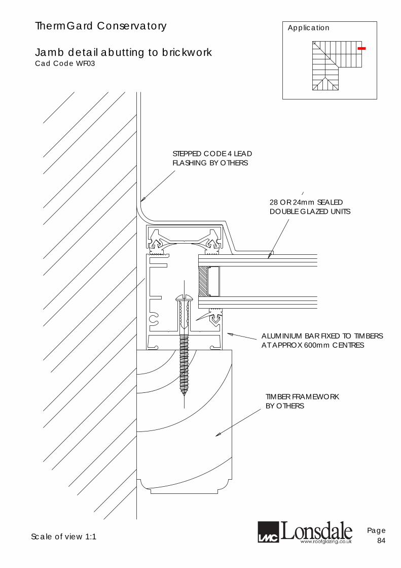
ThermGard Conservatory Jamb detail abutting to brickwork Cad Code WF03
Application
Scale of view 1:1
Page 84
ALUMINIUM BAR FIXED TO TIMBERS AT APPROX 600mm CENTRES
28 OR 24mm SEALED DOUBLE GLAZED UNITS
STEPPED CODE 4 LEAD FLASHING BY OTHERS
TIMBER FRAMEWORK BY OTHERS
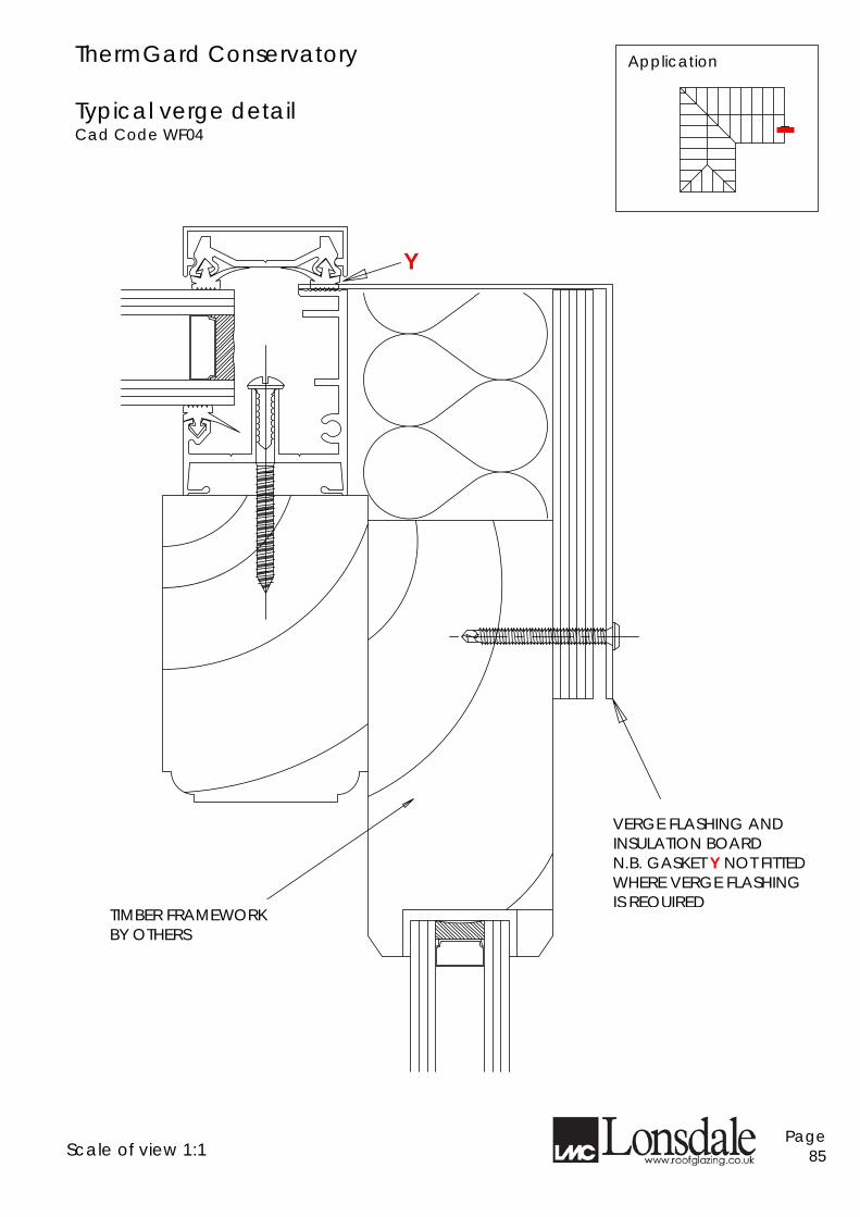
ThermGard Conservatory Typical verge detail Cad Code WF04
Application
TIMBER FRAMEWORK BY OTHERS
VERGE FLASHING AND INSULATION BOARD N.B. GASKET Y NOT FITTED WHERE VERGE FLASHING IS REQUIRED
Y
Scale of view 1:1
Page 85
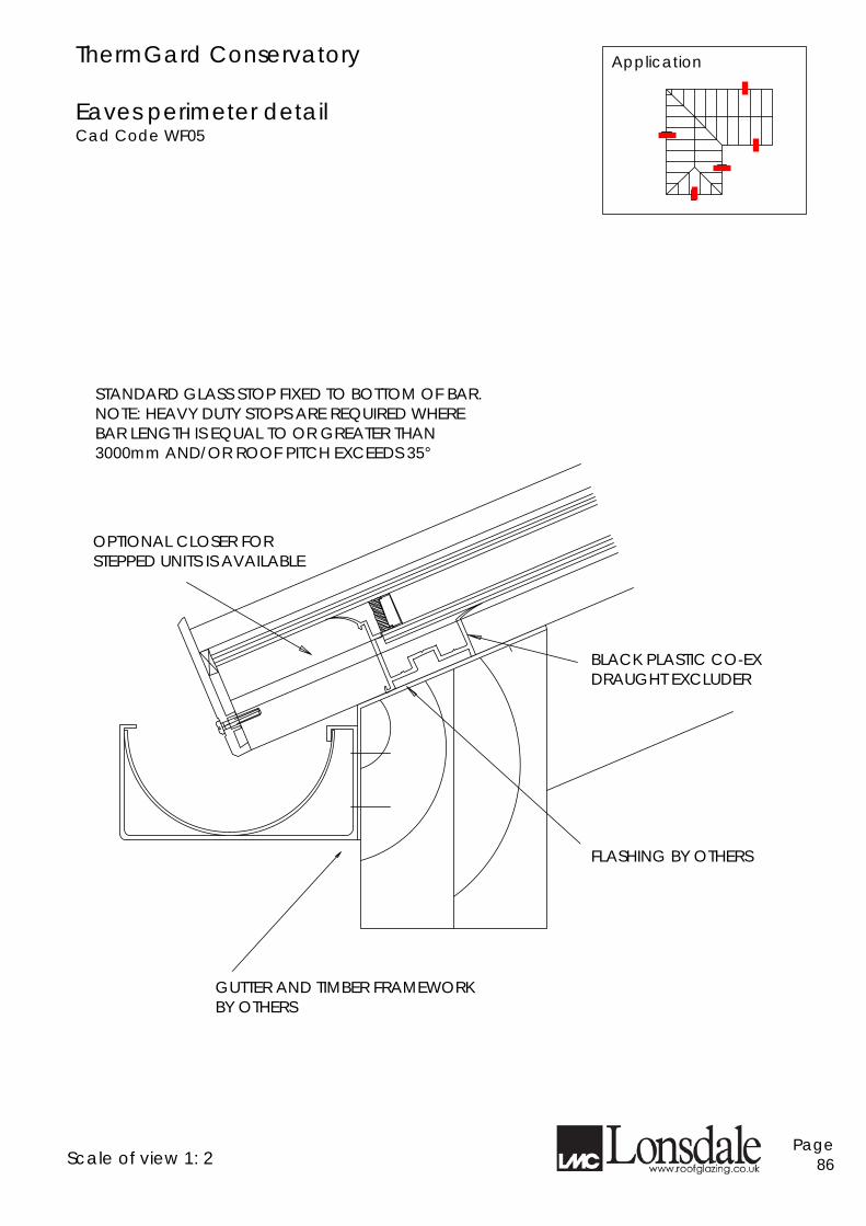
ThermGard Conservatory Eaves perimeter detail Cad Code WF05
FLASHING BY OTHERS
GUTTER AND TIMBER FRAMEWORK BY OTHERS
OPTIONAL CLOSER FOR STEPPED UNITS IS AVAILABLE
STANDARD GLASS STOP FIXED TO BOTTOM OF BAR. NOTE: HEAVY DUTY STOPS ARE REQUIRED WHERE BAR LENGTH IS EQUAL TO OR GREATER THAN 3000mm AND/OR ROOF PITCH EXCEEDS 35°
Scale of view 1: 2
Page 86
Application
BLACK PLASTIC CO-EX DRAUGHT EXCLUDER
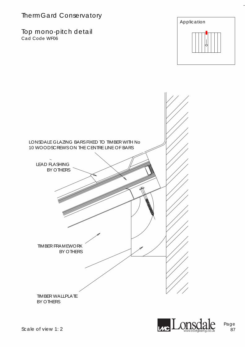
ThermGard Conservatory Top mono-pitch detail Cad Code WF06
TIMBER FRAMEWORK BY OTHERS
TIMBER WALLPLATE BY OTHERS
LEAD FLASHING BY OTHERS
LONSDALE GLAZING BARS FIXED TO TIMBER WITH No 10 WOODSCREWS ON THE CENTRE LINE OF BARS
Application
Scale of view 1: 2
Page 87
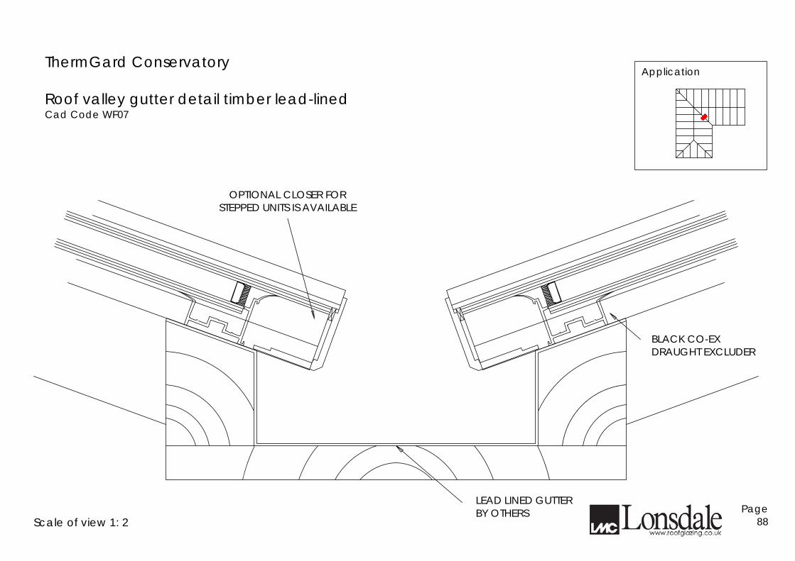
ThermGard Conservatory Roof valley gutter detail timber lead-lined Cad Code WF07
LEAD LINED GUTTER BY OTHERS
OPTIONAL CLOSER FOR STEPPED UNITS IS AVAILABLE
BLACK CO-EX DRAUGHT EXCLUDER
Scale of view 1: 2
Page 88
Application
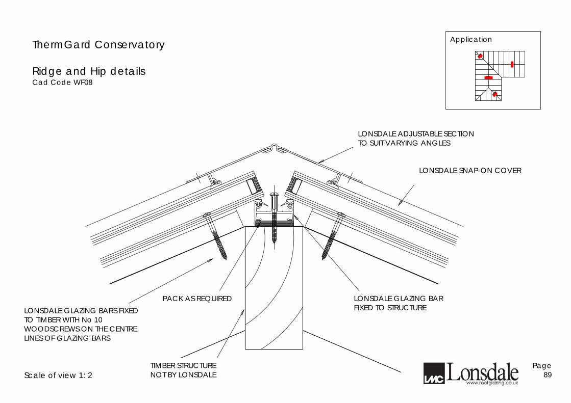
ThermGard Conservatory Ridge and Hip details Cad Code WF08
Application
Scale of view 1: 2
Page 89
LONSDALE ADJUSTABLE SECTION TO SUIT VARYING ANGLES
LONSDALE SNAP-ON COVER
LONSDALE GLAZING BAR FIXED TO STRUCTURE
TIMBER STRUCTURE NOT BY LONSDALE
PACK AS REQUIRED LONSDALE GLAZING BARS FIXED TO TIMBER WITH No 10 WOODSCREWS ON THE CENTRE LINES OF GLAZING BARS
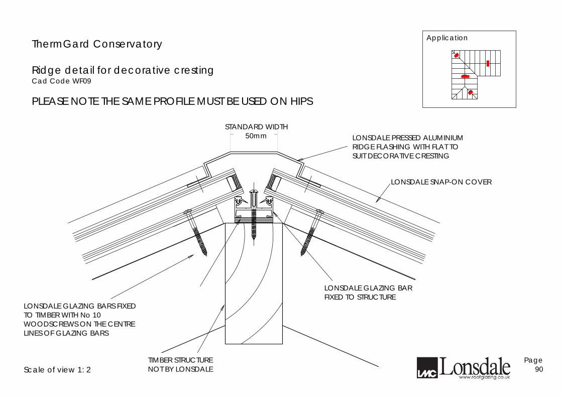
ThermGard Conservatory Ridge detail for decorative cresting Cad Code WF09 PLEASE NOTE THE SAME PROFILE MUST BE USED ON HIPS
Scale of view 1: 2
Page 90
LONSDALE GLAZING BARS FIXED TO TIMBER WITH No 10 WOODSCREWS ON THE CENTRE LINES OF GLAZING BARS
TIMBER STRUCTURE NOT BY LONSDALE
LONSDALE GLAZING BAR FIXED TO STRUCTURE
LONSDALE SNAP-ON COVER
LONSDALE PRESSED ALUMINIUM RIDGE FLASHING WITH FLAT TO SUIT DECORATIVE CRESTING
STANDARD WIDTH 50mm
Application
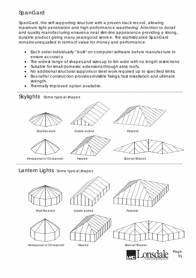
SpanGard SpanGard, the self-supporting structure with a proven track record, allowing maximum light penetration and high performance weathering. Attention to detail and quality manufacturing ensures a neat slim-line appearance providing a strong, durable product giving many years good service. The sophisticated SpanGard remains unequalled in terms of value for money and performance.
• Each order individually " built" on computer software before manufacture to ensure accuracy.
• The widest range of shapes and sizes up to 6m wide with no length restrictions. • Suitable for small domestic extensions through atria roofs. • No additional structural supports or steel work required up to specified limits. • Box-rafter construction provides invisible fixings, fast installation and ultimate
strength. • Thermally improved option available.
Skylights Some typical shapes
Lantern Lights Some typical shapes
Page 91
Muli Faceted Gable ended Pyramid
Hexagonal or Octagonal Hipped Special Shapes
Muli Faceted Gable ended Pyramid
Hexagonal or Octagonal Hipped Special Shapes
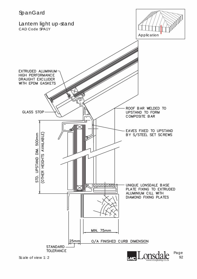
SpanGard Lantern light up-stand CAD Code SPA1Y Scale of view 1: 2
Page 92
TOLERANCETOLERANCE
STANDARDSTANDARD
DIAMOND FIXING PLATESDIAMOND FIXING PLATES
ALUMINIUM CILL WITHALUMINIUM CILL WITH
PLATE FIXING TO EXTRUDEDPLATE FIXING TO EXTRUDED
UNIQUE LONSDALE BASEUNIQUE LONSDALE BASE
O/A FINISHED CURB DIMENSIONO/A FINISHED CURB DIMENSION
GLASS STOPGLASS STOP
WITH EPDM GASKETSWITH EPDM GASKETS
DRAUGHT EXCLUDERDRAUGHT EXCLUDER
HIGH PERFORMANCEHIGH PERFORMANCE
EXTRUDED ALUMINIUMEXTRUDED ALUMINIUM
BY S/STEEL SET SCREWSBY S/STEEL SET SCREWS
EAVES FIXED TO UPSTANDEAVES FIXED TO UPSTAND
COMPOSITE BARCOMPOSITE BAR
UPSTAND TO FORMUPSTAND TO FORM
ROOF BAR WELDED TOROOF BAR WELDED TO
MIN. 75mmMIN. 75mm
25mm25mm
STD. UPSTAND DIM. 500mm
STD. UPSTAND DIM. 500mm
(OTHER HEIGHTS AVAILABLE)
(OTHER HEIGHTS AVAILABLE)
Application
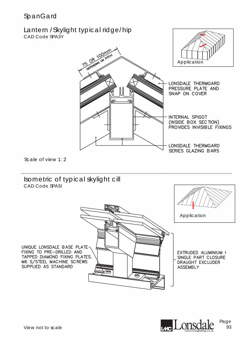
SpanGard Lantern /Skylight typical ridge/hip CAD Code SPA3Y
Isometric of typical skylight cill CAD Code SPA5I View not to scale
Page 93
SERIES GLAZING BARSSERIES GLAZING BARS
LONSDALE THERMGARDLONSDALE THERMGARD
PROVIDES INVISIBLE FIXINGSPROVIDES INVISIBLE FIXINGS
(INSIDE BOX SECTION)(INSIDE BOX SECTION)
INTERNAL SPIGOTINTERNAL SPIGOT
SNAP ON COVERSNAP ON COVER
PRESSURE PLATE ANDPRESSURE PLATE AND
LONSDALE THERMGARDLONSDALE THERMGARD
75 OR 100m
m
75 OR 100m
m
DEPENDING ON
PITC
H
DEPENDING ON
PITC
H
UNIQUE LONSDALE BASE PLATEUNIQUE LONSDALE BASE PLATE
FIXING TO PRE-DRILLED ANDFIXING TO PRE-DRILLED AND
TAPPED DIAMOND FIXING PLATES.TAPPED DIAMOND FIXING PLATES.
M6 S/STEEL MACHINE SCREWSM6 S/STEEL MACHINE SCREWS
SUPPLIED AS STANDARDSUPPLIED AS STANDARD
EXTRUDED ALUMINIUM CEXTRUDED ALUMINIUM CILL,
DRAUGHT EXCLUDERDRAUGHT EXCLUDER
ASSEMBLYASSEMBLY
SINGLE PART CLOSURE SINGLE PART CLOSURE &
Application
Application
Scale of view 1: 2
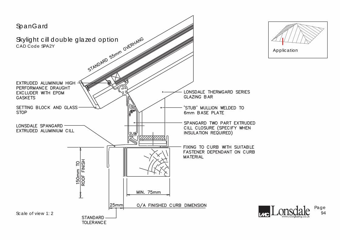
SpanGard
Skylight cill double glazed option CAD Code SPA2Y
Scale of view 1: 2
Page 94
SETTING BLOCK AND GLASSSETTING BLOCK AND GLASS
EXTRUDED ALUMINIUM CILLEXTRUDED ALUMINIUM CILL
LONSDALE SPANGARDLONSDALE SPANGARD
EXCLUDER WITH EPDMEXCLUDER WITH EPDM
PERFORMANCE DRAUGHTPERFORMANCE DRAUGHT
EXTRUDED ALUMINIUM HIGHEXTRUDED ALUMINIUM HIGH
GASKETSGASKETS
STOPSTOP
STANDARD 55m
m OVERHANG
STANDARD 55m
m OVERHANG
FASTENER DEPENDANT ON CURBFASTENER DEPENDANT ON CURB
FIXING TO CURB WITH SUITABLEFIXING TO CURB WITH SUITABLE
MATERIALMATERIAL
INSULATION REQUIRED)INSULATION REQUIRED)
CILL CLOSURE (SPECIFY WHENCILL CLOSURE (SPECIFY WHEN
SPANGARD TWO PART EXTRUDEDSPANGARD TWO PART EXTRUDED
6mm BASE PLATE6mm BASE PLATE
'STUB' MULLION WELDED TO'STUB' MULLION WELDED TO
LONSDALE THERMGARD SERIESLONSDALE THERMGARD SERIES
GLAZING BARGLAZING BAR
TOLERANCETOLERANCE
STANDARDSTANDARD
O/A FINISHED CURB DIMENSIONO/A FINISHED CURB DIMENSION
MIN. 75mmMIN. 75mm
25mm25mm
150mm TO
150mm TO
ROOF FINISH
ROOF FINISH
Application
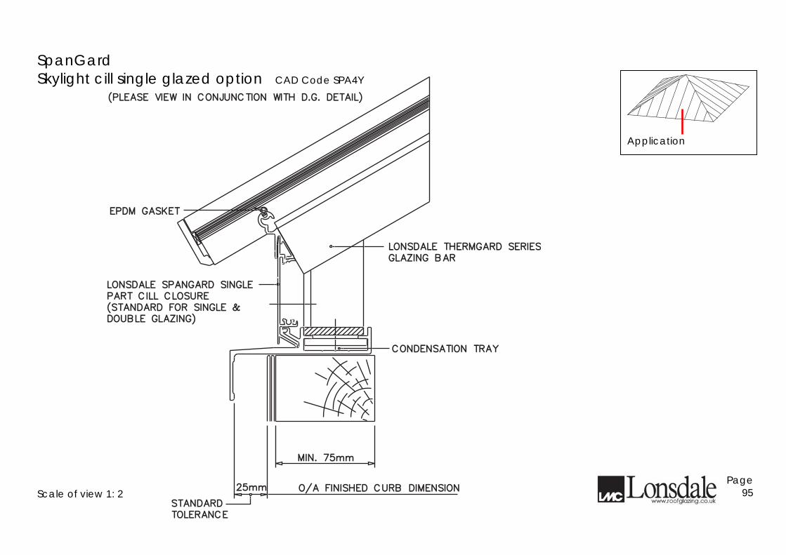
SpanGard
Skylight cill single glazed option CAD Code SPA4Y
Scale of view 1: 2
Page 95
(STANDARD FOR SINGLE &(STANDARD FOR SINGLE &
PART CILL CLOSUREPART CILL CLOSURE
LONSDALE SPANGARD SINGLELONSDALE SPANGARD SINGLE
DOUBLE GLAZING)DOUBLE GLAZING)
EPDM GASKETEPDM GASKET
O/A FINISHED CURB DIMENSIONO/A FINISHED CURB DIMENSION
STANDARDSTANDARD
TOLERANCETOLERANCE
LONSDALE THERMGARD SERIESLONSDALE THERMGARD SERIES
CONDENSATION TRAYCONDENSATION TRAY
GLAZING BARGLAZING BAR
(PLEASE VIEW IN CONJUNCTION WITH D.G. DETAIL)(PLEASE VIEW IN CONJUNCTION WITH D.G. DETAIL)
25mm25mm
MIN. 75mmMIN. 75mm
Application
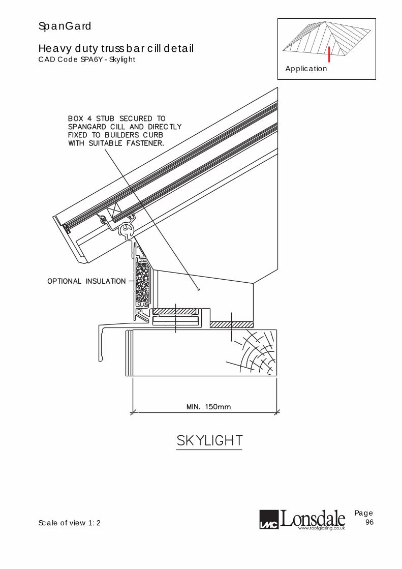
SpanGard Heavy duty truss bar cill detail CAD Code SPA6Y - Skylight
Scale of view 1: 2
Page 96
OPTIONAL INSULATIONOPTIONAL INSULATION
BOX 4 STUB SECURED TOBOX 4 STUB SECURED TO
SPANGARD CILL AND DIRECTLYSPANGARD CILL AND DIRECTLY
FIXED TO BUILDERS CURBFIXED TO BUILDERS CURB
WITH SUITABLE FASTENER.WITH SUITABLE FASTENER.
SKYLIGHTSKYLIGHT
MIN. 150mmMIN. 150mm
Application
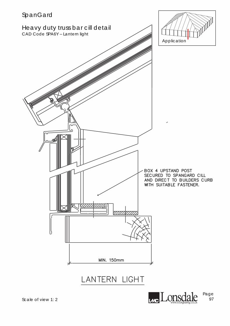
SpanGard Heavy duty truss bar cill detail CAD Code SPA6Y – Lantern light
Scale of view 1: 2
Page 97
WITH SUITABLE FASTENER.WITH SUITABLE FASTENER.
BOX 4 UPSTAND POSTBOX 4 UPSTAND POST
SECURED TO SPANGARD CILLSECURED TO SPANGARD CILL
AND DIRECT TO BUILDERS CURBAND DIRECT TO BUILDERS CURB
LANTERN LIGHTLANTERN LIGHT
MIN. 150mmMIN. 150mm
Application
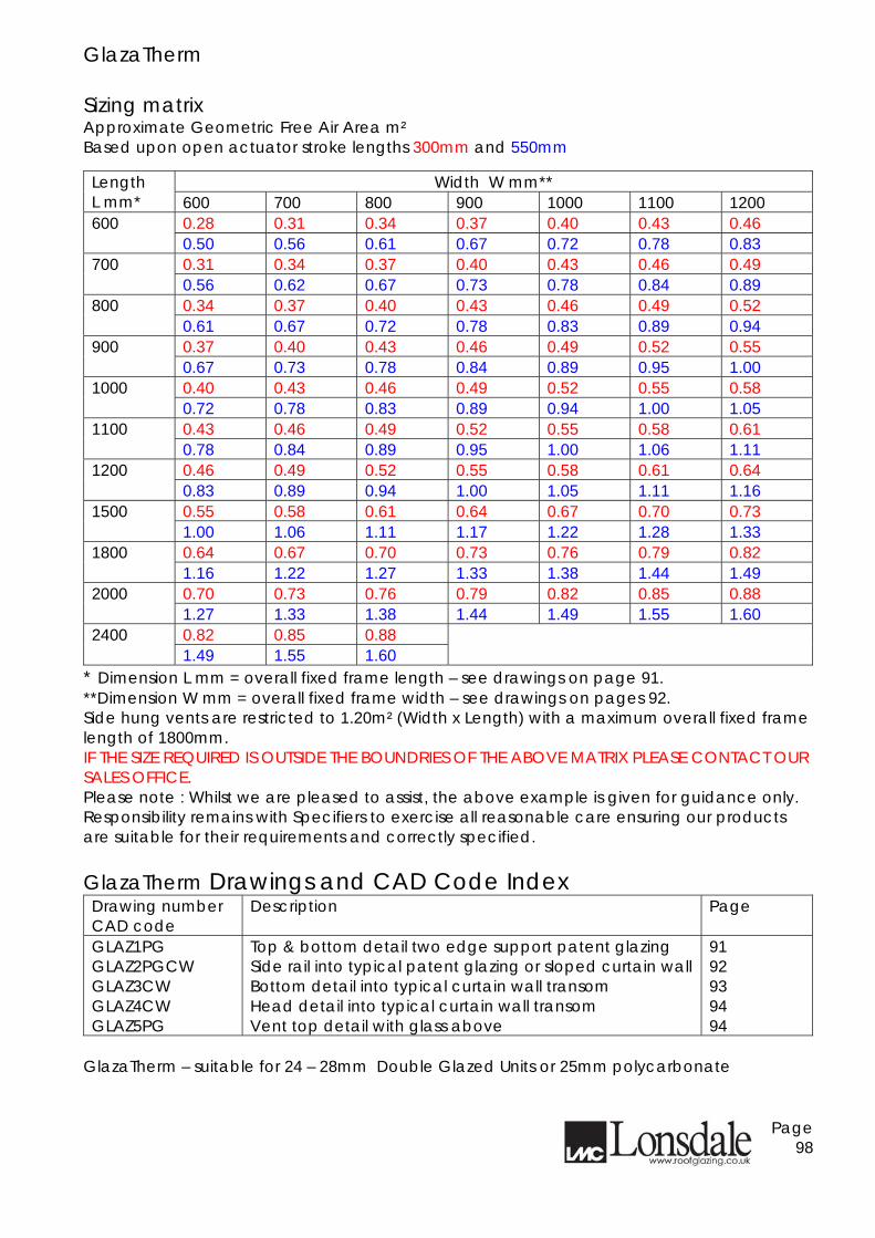
GlazaTherm Sizing matrix Approximate Geometric Free Air Area m² Based upon open actuator stroke lengths 300mm and 550mm
Width W mm** Length L mm* 600 700 800 900 1000 1100 1200
0.28 0.31 0.34 0.37 0.40 0.43 0.46 600 0.50 0.56 0.61 0.67 0.72 0.78 0.83 0.31 0.34 0.37 0.40 0.43 0.46 0.49 700 0.56 0.62 0.67 0.73 0.78 0.84 0.89 0.34 0.37 0.40 0.43 0.46 0.49 0.52 800 0.61 0.67 0.72 0.78 0.83 0.89 0.94 0.37 0.40 0.43 0.46 0.49 0.52 0.55 900 0.67 0.73 0.78 0.84 0.89 0.95 1.00 0.40 0.43 0.46 0.49 0.52 0.55 0.58 1000 0.72 0.78 0.83 0.89 0.94 1.00 1.05 0.43 0.46 0.49 0.52 0.55 0.58 0.61 1100 0.78 0.84 0.89 0.95 1.00 1.06 1.11 0.46 0.49 0.52 0.55 0.58 0.61 0.64 1200 0.83 0.89 0.94 1.00 1.05 1.11 1.16 0.55 0.58 0.61 0.64 0.67 0.70 0.73 1500 1.00 1.06 1.11 1.17 1.22 1.28 1.33 0.64 0.67 0.70 0.73 0.76 0.79 0.82 1800 1.16 1.22 1.27 1.33 1.38 1.44 1.49 0.70 0.73 0.76 0.79 0.82 0.85 0.88 2000 1.27 1.33 1.38 1.44 1.49 1.55 1.60 0.82 0.85 0.88 2400 1.49 1.55 1.60
**Dimension L mm = overall fixed frame length – see drawings on page 91. **Dimension W mm = overall fixed frame width – see drawings on pages 92. Side hung vents are restricted to 1.20m² (Width x Length) with a maximum overall fixed frame length of 1800mm. IF THE SIZE REQUIRED IS OUTSIDE THE BOUNDRIES OF THE ABOVE MATRIX PLEASE CONTACT OUR SALES OFFICE. Please note : Whilst we are pleased to assist, the above example is given for guidance only. Responsibility remains with Specifiers to exercise all reasonable care ensuring our products are suitable for their requirements and correctly specified. GlazaTherm Drawings and CAD Code Index Drawing number CAD code
Description Page
GLAZ1PG GLAZ2PGCW GLAZ3CW GLAZ4CW GLAZ5PG
Top & bottom detail two edge support patent glazing Side rail into typical patent glazing or sloped curtain wall Bottom detail into typical curtain wall transom Head detail into typical curtain wall transom Vent top detail with glass above
91 92 93 94 94
GlazaTherm – suitable for 24 – 28mm Double Glazed Units or 25mm polycarbonate
Page 98
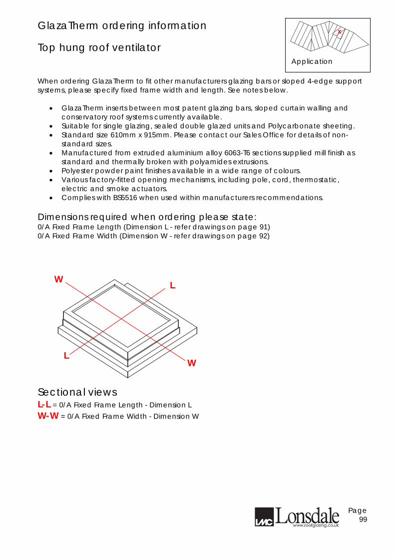
GlazaTherm ordering information Top hung roof ventilator
When ordering GlazaTherm to fit other manufacturers glazing bars or sloped 4-edge support systems, please specify fixed frame width and length. See notes below.
• GlazaTherm inserts between most patent glazing bars, sloped curtain walling and conservatory roof systems currently available.
• Suitable for single glazing, sealed double glazed units and Polycarbonate sheeting. • Standard size 610mm x 915mm. Please contact our Sales Office for details of non-
standard sizes. • Manufactured from extruded aluminium alloy 6063-T6 sections supplied mill finish as
standard and thermally broken with polyamides extrusions. • Polyester powder paint finishes available in a wide range of colours. • Various factory-fitted opening mechanisms, including pole, cord, thermostatic,
electric and smoke actuators. • Complies with BS5516 when used within manufacturers recommendations.
Dimensions required when ordering please state: 0/A Fixed Frame Length (Dimension L - refer drawings on page 91) 0/A Fixed Frame Width (Dimension W - refer drawings on page 92) Sectional views L-L = 0/A Fixed Frame Length - Dimension L W-W = 0/A Fixed Frame Width - Dimension W
Page 99
Application
x
L
L
W
W
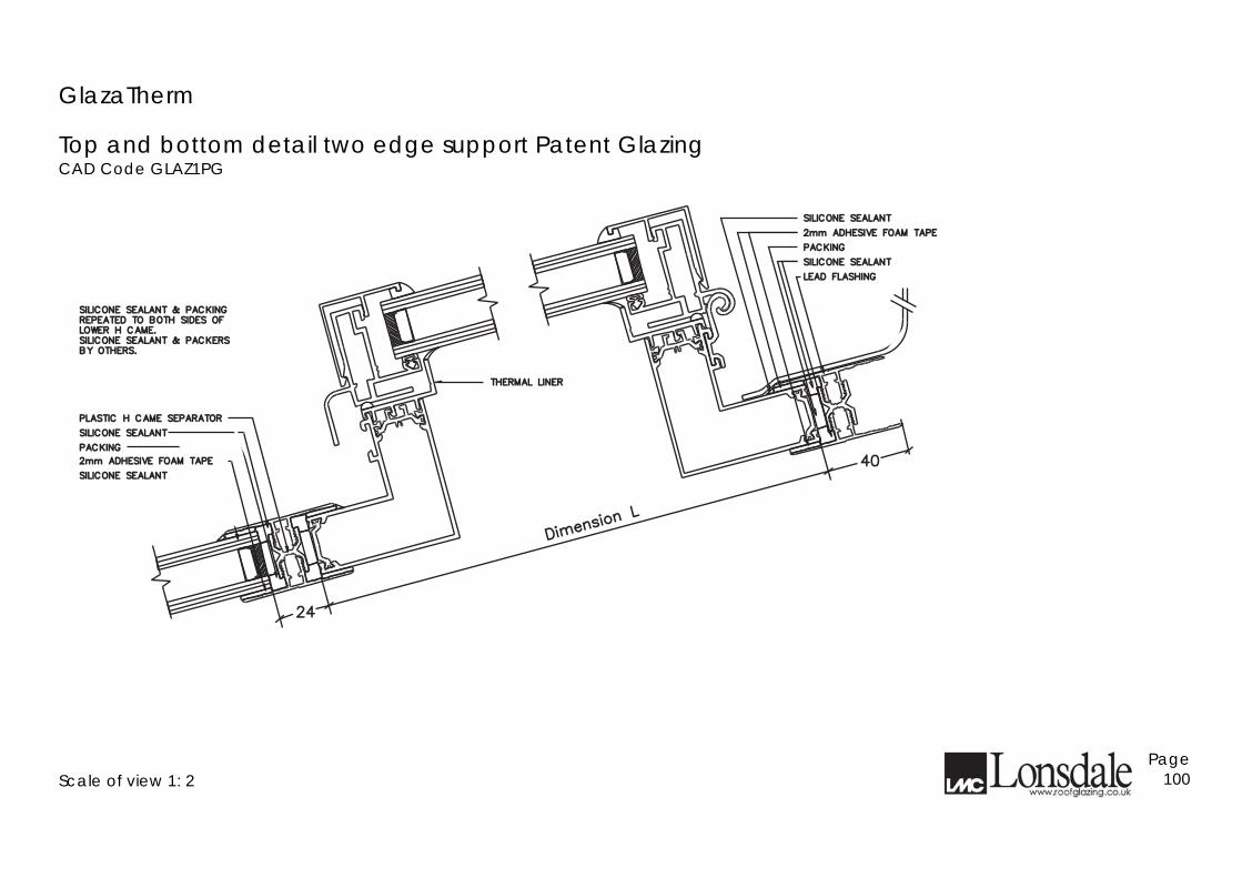
GlazaTherm
Top and bottom detail two edge support Patent Glazing CAD Code GLAZ1PG
Scale of view 1: 2
Page 100
2424
4040
Dimensi
on L
Dimensi
on L
SILICONE SEALANTSILICONE SEALANT
2mm ADHESIVE FOAM TAPE2mm ADHESIVE FOAM TAPE
PACKINGPACKING
SILICONE SEALANTSILICONE SEALANT
LEAD FLASHINGLEAD FLASHING
SILICONE SEALANTSILICONE SEALANT
2mm ADHESIVE FOAM TAPE2mm ADHESIVE FOAM TAPE
PACKINGPACKING
SILICONE SEALANTSILICONE SEALANT
PLASTIC H CAME SEPARATORPLASTIC H CAME SEPARATOR
SILICONE SEALANT & PACKINGSILICONE SEALANT & PACKINGREPEATED TO BOTH SIDES OFREPEATED TO BOTH SIDES OFLOWER H CAME.LOWER H CAME.SILICONE SEALANT & PACKERSSILICONE SEALANT & PACKERSBY OTHERS.BY OTHERS.
THERMAL LINERTHERMAL LINER
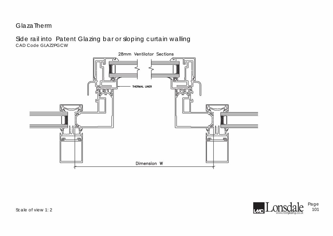
GlazaTherm
Side rail into Patent Glazing bar or sloping curtain walling CAD Code GLAZ2PGCW
Scale of view 1: 2
Page 101
Dimension WDimension W
28mm Ventilator Sections28mm Ventilator Sections
THERMAL LINERTHERMAL LINER
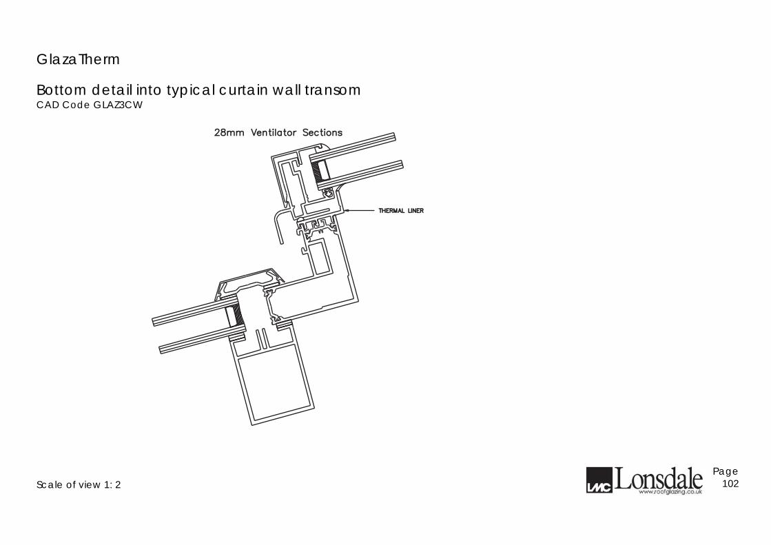
GlazaTherm
Bottom detail into typical curtain wall transom CAD Code GLAZ3CW
Scale of view 1: 2
Page 102
28mm Ventilator Sections28mm Ventilator Sections
THERMAL LINERTHERMAL LINER
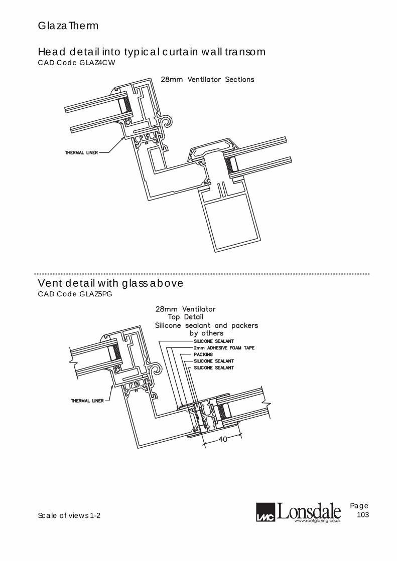
GlazaTherm Head detail into typical curtain wall transom CAD Code GLAZ4CW
Vent detail with glass above CAD Code GLAZ5PG
Scale of views 1-2
Page 103
28mm Ventilator Sections28mm Ventilator Sections
THERMAL LINERTHERMAL LINER
4040
28mm Ventilator28mm VentilatorTop DetailTop Detail
Silicone sealant and packersSilicone sealant and packersby othersby others
THERMAL LINERTHERMAL LINER
SILICONE SEALANTSILICONE SEALANT
2mm ADHESIVE FOAM TAPE2mm ADHESIVE FOAM TAPE
PACKINGPACKING
SILICONE SEALANTSILICONE SEALANT
SILICONE SEALANTSILICONE SEALANT
Research & Development Lonsdale has made a very significant investment in research and development to bring you the products set out in this publication. Lonsdale's intention is to continue to invest to stay at the fore front of its Industry and bring its customers products with unrivalled technological advancements and standards. We reserve the right to make changes without prior notification to achieve these aims. Lonsdale will attack any Infringement of its copyright in order that both its customers and the Company may obtain the full benefits of its endeavours. Any unauthorised copying or reproduction of the plans and ideas whose copyright belongs to Lonsdale in this brochure will be met by legal action from the Company's solicitors Messrs. H. Montlake & Co.
Page 104
July 2010
www.roofglazing.co.uk Page 105