Embed Size (px)
Citation preview
LogiCORE IP Video Timing Controller v5.01aProduct Guide
PG016 October 16, 2012
Video Timing Controller 5.01a www.xilinx.com 2PG016 October 16, 2012
Table of Contents
SECTION I: SUMMARY
IP Facts
Chapter 1: OverviewFeature Summary. . . . . . . . . . . . . . . . . . . . . . . . . . . . . . . . . . . . . . . . . . . . . . . . . . . . . . . . . . . . . . . . . . 9Applications . . . . . . . . . . . . . . . . . . . . . . . . . . . . . . . . . . . . . . . . . . . . . . . . . . . . . . . . . . . . . . . . . . . . . 10Unsupported Features. . . . . . . . . . . . . . . . . . . . . . . . . . . . . . . . . . . . . . . . . . . . . . . . . . . . . . . . . . . . . 10Licensing and Ordering Information . . . . . . . . . . . . . . . . . . . . . . . . . . . . . . . . . . . . . . . . . . . . . . . . . . 10
Chapter 2: Product SpecificationStandards . . . . . . . . . . . . . . . . . . . . . . . . . . . . . . . . . . . . . . . . . . . . . . . . . . . . . . . . . . . . . . . . . . . . . . . 11Performance. . . . . . . . . . . . . . . . . . . . . . . . . . . . . . . . . . . . . . . . . . . . . . . . . . . . . . . . . . . . . . . . . . . . . 11Resource Utilization. . . . . . . . . . . . . . . . . . . . . . . . . . . . . . . . . . . . . . . . . . . . . . . . . . . . . . . . . . . . . . . 12Core Interfaces and Register Space . . . . . . . . . . . . . . . . . . . . . . . . . . . . . . . . . . . . . . . . . . . . . . . . . . 23
Chapter 3: Designing with the CoreBasic Architecture . . . . . . . . . . . . . . . . . . . . . . . . . . . . . . . . . . . . . . . . . . . . . . . . . . . . . . . . . . . . . . . . 44Control Signals and Timing . . . . . . . . . . . . . . . . . . . . . . . . . . . . . . . . . . . . . . . . . . . . . . . . . . . . . . . . . 45Use Model . . . . . . . . . . . . . . . . . . . . . . . . . . . . . . . . . . . . . . . . . . . . . . . . . . . . . . . . . . . . . . . . . . . . . . 58Clocking. . . . . . . . . . . . . . . . . . . . . . . . . . . . . . . . . . . . . . . . . . . . . . . . . . . . . . . . . . . . . . . . . . . . . . . . . 59Resets . . . . . . . . . . . . . . . . . . . . . . . . . . . . . . . . . . . . . . . . . . . . . . . . . . . . . . . . . . . . . . . . . . . . . . . . . . 59Protocol Description . . . . . . . . . . . . . . . . . . . . . . . . . . . . . . . . . . . . . . . . . . . . . . . . . . . . . . . . . . . . . . 59
SECTION II: VIVADO DESIGN SUITE
Chapter 4: Customizing and Generating the CoreGraphical User Interface . . . . . . . . . . . . . . . . . . . . . . . . . . . . . . . . . . . . . . . . . . . . . . . . . . . . . . . . . . . 61Output Generation. . . . . . . . . . . . . . . . . . . . . . . . . . . . . . . . . . . . . . . . . . . . . . . . . . . . . . . . . . . . . . . . 67
Video Timing Controller 5.01a www.xilinx.com 3PG016 October 16, 2012
Chapter 5: Constraining the CoreRequired Constraints . . . . . . . . . . . . . . . . . . . . . . . . . . . . . . . . . . . . . . . . . . . . . . . . . . . . . . . . . . . . . . 68Device, Package, and Speed Grade Selections. . . . . . . . . . . . . . . . . . . . . . . . . . . . . . . . . . . . . . . . . . 68Clock Frequencies . . . . . . . . . . . . . . . . . . . . . . . . . . . . . . . . . . . . . . . . . . . . . . . . . . . . . . . . . . . . . . . . 69Clock Management . . . . . . . . . . . . . . . . . . . . . . . . . . . . . . . . . . . . . . . . . . . . . . . . . . . . . . . . . . . . . . . 69Clock Placement. . . . . . . . . . . . . . . . . . . . . . . . . . . . . . . . . . . . . . . . . . . . . . . . . . . . . . . . . . . . . . . . . . 69Banking . . . . . . . . . . . . . . . . . . . . . . . . . . . . . . . . . . . . . . . . . . . . . . . . . . . . . . . . . . . . . . . . . . . . . . . . . 69Transceiver Placement . . . . . . . . . . . . . . . . . . . . . . . . . . . . . . . . . . . . . . . . . . . . . . . . . . . . . . . . . . . . 69I/O Standard and Placement. . . . . . . . . . . . . . . . . . . . . . . . . . . . . . . . . . . . . . . . . . . . . . . . . . . . . . . . 69
Chapter 6: Detailed Example DesignDemonstration Test Bench . . . . . . . . . . . . . . . . . . . . . . . . . . . . . . . . . . . . . . . . . . . . . . . . . . . . . . . . . 70
SECTION III: ISE DESIGN SUITE
Chapter 7: Customizing and Generating the CoreGraphical User Interface . . . . . . . . . . . . . . . . . . . . . . . . . . . . . . . . . . . . . . . . . . . . . . . . . . . . . . . . . . . 77Parameter Values in the XCO File . . . . . . . . . . . . . . . . . . . . . . . . . . . . . . . . . . . . . . . . . . . . . . . . . . . . 84Output Generation. . . . . . . . . . . . . . . . . . . . . . . . . . . . . . . . . . . . . . . . . . . . . . . . . . . . . . . . . . . . . . . . 87
Chapter 8: Constraining the CoreRequired Constraints . . . . . . . . . . . . . . . . . . . . . . . . . . . . . . . . . . . . . . . . . . . . . . . . . . . . . . . . . . . . . . 88Device, Package, and Speed Grade Selections. . . . . . . . . . . . . . . . . . . . . . . . . . . . . . . . . . . . . . . . . . 88Clock Frequencies . . . . . . . . . . . . . . . . . . . . . . . . . . . . . . . . . . . . . . . . . . . . . . . . . . . . . . . . . . . . . . . . 89Clock Management . . . . . . . . . . . . . . . . . . . . . . . . . . . . . . . . . . . . . . . . . . . . . . . . . . . . . . . . . . . . . . . 89Clock Placement. . . . . . . . . . . . . . . . . . . . . . . . . . . . . . . . . . . . . . . . . . . . . . . . . . . . . . . . . . . . . . . . . . 89Banking . . . . . . . . . . . . . . . . . . . . . . . . . . . . . . . . . . . . . . . . . . . . . . . . . . . . . . . . . . . . . . . . . . . . . . . . . 89Transceiver Placement . . . . . . . . . . . . . . . . . . . . . . . . . . . . . . . . . . . . . . . . . . . . . . . . . . . . . . . . . . . . 89I/O Standard and Placement. . . . . . . . . . . . . . . . . . . . . . . . . . . . . . . . . . . . . . . . . . . . . . . . . . . . . . . . 89
Chapter 9: Detailed Example DesignDemonstration Test Bench . . . . . . . . . . . . . . . . . . . . . . . . . . . . . . . . . . . . . . . . . . . . . . . . . . . . . . . . . 90Test Bench Structure . . . . . . . . . . . . . . . . . . . . . . . . . . . . . . . . . . . . . . . . . . . . . . . . . . . . . . . . . . . . . . 90Running the Simulation . . . . . . . . . . . . . . . . . . . . . . . . . . . . . . . . . . . . . . . . . . . . . . . . . . . . . . . . . . . . 91Directory and File Contents. . . . . . . . . . . . . . . . . . . . . . . . . . . . . . . . . . . . . . . . . . . . . . . . . . . . . . . . . 91
SECTION IV: APPENDICES
Video Timing Controller 5.01a www.xilinx.com 4PG016 October 16, 2012
Appendix A: Verification, Compliance, and InteroperabilitySimulation . . . . . . . . . . . . . . . . . . . . . . . . . . . . . . . . . . . . . . . . . . . . . . . . . . . . . . . . . . . . . . . . . . . . . . 94Hardware Testing. . . . . . . . . . . . . . . . . . . . . . . . . . . . . . . . . . . . . . . . . . . . . . . . . . . . . . . . . . . . . . . . . 94
Appendix B: MigratingMigrating to the AXI4-Lite Interface. . . . . . . . . . . . . . . . . . . . . . . . . . . . . . . . . . . . . . . . . . . . . . . . . . 96Parameter Changes in the XCO File . . . . . . . . . . . . . . . . . . . . . . . . . . . . . . . . . . . . . . . . . . . . . . . . . . 96Port Changes . . . . . . . . . . . . . . . . . . . . . . . . . . . . . . . . . . . . . . . . . . . . . . . . . . . . . . . . . . . . . . . . . . . . 97Functionality Changes . . . . . . . . . . . . . . . . . . . . . . . . . . . . . . . . . . . . . . . . . . . . . . . . . . . . . . . . . . . . . 98Special Considerations when Migrating to AXI . . . . . . . . . . . . . . . . . . . . . . . . . . . . . . . . . . . . . . . . . 98
Appendix C: DebuggingBringing up the AXI4-Lite Interface. . . . . . . . . . . . . . . . . . . . . . . . . . . . . . . . . . . . . . . . . . . . . . . . . . . 99
Appendix D: Application Software DevelopmentDevice Drivers . . . . . . . . . . . . . . . . . . . . . . . . . . . . . . . . . . . . . . . . . . . . . . . . . . . . . . . . . . . . . . . . . . 101pCore API Functions. . . . . . . . . . . . . . . . . . . . . . . . . . . . . . . . . . . . . . . . . . . . . . . . . . . . . . . . . . . . . . 102
Appendix E: Additional ResourcesXilinx Resources . . . . . . . . . . . . . . . . . . . . . . . . . . . . . . . . . . . . . . . . . . . . . . . . . . . . . . . . . . . . . . . . . 105Solution Centers. . . . . . . . . . . . . . . . . . . . . . . . . . . . . . . . . . . . . . . . . . . . . . . . . . . . . . . . . . . . . . . . . 105References . . . . . . . . . . . . . . . . . . . . . . . . . . . . . . . . . . . . . . . . . . . . . . . . . . . . . . . . . . . . . . . . . . . . . 105Technical Support . . . . . . . . . . . . . . . . . . . . . . . . . . . . . . . . . . . . . . . . . . . . . . . . . . . . . . . . . . . . . . . 106Revision History . . . . . . . . . . . . . . . . . . . . . . . . . . . . . . . . . . . . . . . . . . . . . . . . . . . . . . . . . . . . . . . . . 106Notice of Disclaimer. . . . . . . . . . . . . . . . . . . . . . . . . . . . . . . . . . . . . . . . . . . . . . . . . . . . . . . . . . . . . . 106
Video Timing Controller 5.01a www.xilinx.com 5PG016 October 16, 2012
SECTION I: SUMMARY
IP Facts
Overview
Product Specification
Designing with the Core
Video Timing Controller 5.01a www.xilinx.com 6PG016 October 16, 2012 Product Specification
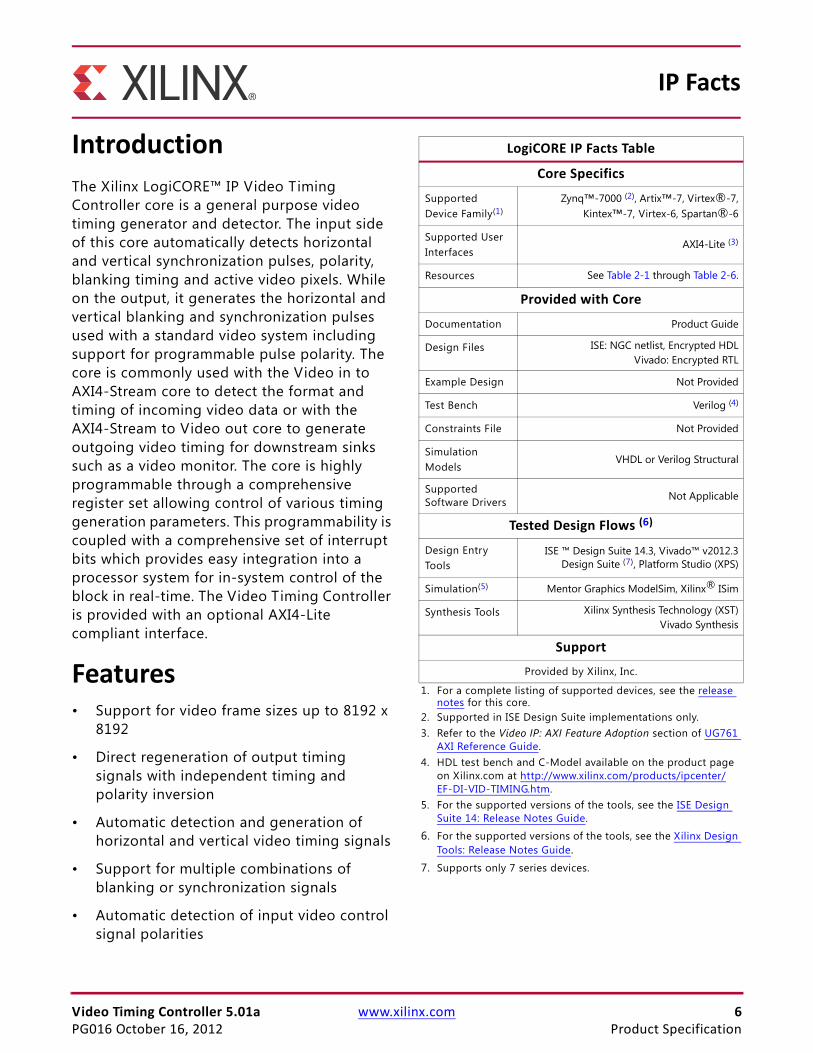
IntroductionThe Xilinx LogiCORE™ IP Video Timing Controller core is a general purpose video timing generator and detector. The input side of this core automatically detects horizontal and vertical synchronization pulses, polarity, blanking timing and active video pixels. While on the output, it generates the horizontal and vertical blanking and synchronization pulses used with a standard video system including support for programmable pulse polarity. The core is commonly used with the Video in to AXI4-Stream core to detect the format and timing of incoming video data or with the AXI4-Stream to Video out core to generate outgoing video timing for downstream sinks such as a video monitor. The core is highly programmable through a comprehensive register set allowing control of various timing generation parameters. This programmability is coupled with a comprehensive set of interrupt bits which provides easy integration into a processor system for in-system control of the block in real-time. The Video Timing Controller is provided with an optional AXI4-Lite compliant interface.
Features• Support for video frame sizes up to 8192 x
8192
• Direct regeneration of output timing signals with independent timing and polarity inversion
• Automatic detection and generation of horizontal and vertical video timing signals
• Support for multiple combinations of blanking or synchronization signals
• Automatic detection of input video control signal polarities
IP Facts
LogiCORE IP Facts Table
Core Specifics
Supported Device Family(1)
Zynq™-7000 (2), Artix™-7, Virtex®-7,Kintex™-7, Virtex-6, Spartan®-6
Supported User Interfaces
AXI4-Lite (3)
Resources See Table 2-1 through Table 2-6.
Provided with Core
Documentation Product Guide
Design Files ISE: NGC netlist, Encrypted HDLVivado: Encrypted RTL
Example Design Not Provided
Test Bench Verilog (4)
Constraints File Not Provided
Simulation Models
VHDL or Verilog Structural
Supported Software Drivers Not Applicable
Tested Design Flows (6)
Design Entry Tools
ISE ™ Design Suite 14.3, Vivado™ v2012.3Design Suite (7), Platform Studio (XPS)
Simulation(5) Mentor Graphics ModelSim, Xilinx® ISim
Synthesis Tools Xilinx Synthesis Technology (XST)Vivado Synthesis
Support
Provided by Xilinx, Inc.
1. For a complete listing of supported devices, see the release notes for this core.
2. Supported in ISE Design Suite implementations only.3. Refer to the Video IP: AXI Feature Adoption section of UG761
AXI Reference Guide.4. HDL test bench and C-Model available on the product page
on Xilinx.com at http://www.xilinx.com/products/ipcenter/EF-DI-VID-TIMING.htm.
5. For the supported versions of the tools, see the ISE Design Suite 14: Release Notes Guide.
6. For the supported versions of the tools, see the Xilinx Design Tools: Release Notes Guide.
7. Supports only 7 series devices.
Video Timing Controller 5.01a www.xilinx.com 7PG016 October 16, 2012 Product Specification
• Support for detection and generation of horizontal delay of vertical blank/sync
• Programmable output video signal polarities
• Generation of up to 16 additional independent output frame synchronization signals Optional AXI4-Lite processor interface
• High number of interrupts and status registers for easy system control and integration
Video Timing Controller 5.01a www.xilinx.com 8PG016 October 16, 2012
Chapter 1
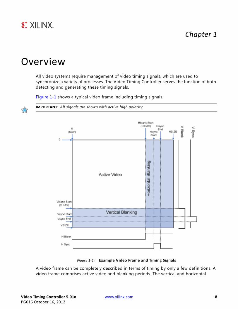
OverviewAll video systems require management of video timing signals, which are used to synchronize a variety of processes. The Video Timing Controller serves the function of both detecting and generating these timing signals.
Figure 1-1 shows a typical video frame including timing signals.
IMPORTANT: All signals are shown with active high polarity.
A video frame can be completely described in terms of timing by only a few definitions. A video frame comprises active video and blanking periods. The vertical and horizontal
X-Ref Target - Figure 1-1
Figure 1-1: Example Video Frame and Timing Signals
Video Timing Controller 5.01a www.xilinx.com 9PG016 October 16, 2012
Feature Summary
synchronization signals describe the video frame timing, which includes active and blanking data. In addition, the frame synchronization signals can be used to synchronize video data from one component to another within a video system. There are additional signals that can also be used to control the video system, such as a signal to differentiate valid chroma samples.
Video systems may utilize different combinations of blank, synchronization or active signals with various polarities to synchronize processing and control video data. The Video Timing Controller simplif ies working with video timing signals by providing a highly programmable and flexible core that allows detection and generation of the various timing signals within a video system.
Feature SummaryThe Video Timing Controller core supports the AXI4-Lite interface and a constant-mode interface. The AXI4-Lite interface allows the core to be easily incorporated into an EDK project. The Constant interface utilizes core parameters configurable by the Graphical User Interface (GUI) to setup the core for f ixed-mode operation. These configurable options allow the Video Timing Controller core to be easily integrated with AXI4 based processor systems, with non-AXI4-compliant processors systems with some additional logic, and in systems without a processor.
The Video Timing Controller core supports detecting video frame sizes up to 8192 clocks by 8192 lines (including horizontal and vertical blanking). The Video Timing Controller core automatically detects the timing involved with horizontal/vertical blanks and syncs. The timing of the active_video and the active_chroma signals are also detected. This allows the user to easily determine the video frame size via the core register (AXI4-Lite) interface. The minimum set of signals used for detection is either vertical blank, horizontal blank and active video or vertical sync, horizontal sync and active video. The polarities of each input signal is also detected and reported via the register interface to allow easy use of each signal once the polarity is known.
The core also supports generating and regenerating (matching the detected input) video frame sizes up to 8192 clocks by 8192 lines (including blanking time). The output can be the same format or a different format as the detected input. This allows detecting one format and generating a different format. The output can also be synchronized to the detected input and has separate signal polarity settings as well. This allows regenerating the input with different signal polarities or with slight timing adjustments (such as delayed or shorted active video).
The Video Timing Controller core supports up to 16 frame sync output signals. These are toggled high for one clock cycle during each frame. These frame syncs allow triggering timing critical hardware processes at different times during a frame.
Video Timing Controller 5.01a www.xilinx.com 10PG016 October 16, 2012
Applications
Applications• Video Surveillance
• Industrial Imaging
• Video Conferencing
• Machine Vision
• Video Systems requiring timing detection or timing generation
Unsupported FeaturesThe Video Timing Controller core does not automatically detect and regenerate timing signals with the same polarity at the output as on the input. Software that can read the polarity of the input signals and set the polarity at the output is needed to configure the Video Timing Controller in this manner.
Licensing and Ordering InformationThis Xilinx LogiCORE IP module is provided under the terms of the Xilinx Core License Agreement. The module is shipped as part of the Vivado Design Suite/ISE Design Suite. For full access to all core functionalities in simulation and in hardware, you must purchase a license for the core. Contact your local Xilinx sales representative for information about pricing and availability.
For more information, visit the Video Timing Controller product web page.
Information about other Xilinx LogiCORE IP modules is available at the Xilinx Intellectual Property page. For information on pricing and availability of other Xilinx LogiCORE IP modules and tools, contact your local Xilinx sales representative.
Video Timing Controller 5.01a www.xilinx.com 11PG016 October 16, 2012 Product Specification
Chapter 2
Product Specification
StandardsThe Video Timing Controller core is compliant with the AXI4-Lite interconnect standards. Refer to the Video IP: AXI Feature Adoption section of the AXI Reference Guide (UG761) [Ref 1] for additional information.
PerformanceThe following sections detail the performance characteristics of the Video Timing Controller core.
Maximum FrequenciesThis section contains typical clock frequencies for the target devices. The maximum achievable clock frequency can vary. The maximum achievable clock frequency and all resource counts can be affected by other tool options, additional logic in the FPGA device, using a different version of Xilinx tools and other factors. Refer to in Table 2-1 through Table 2-6 for device-specific information.
• Virtex-7, Virtex-6, Kintex-7, Zynq (XC7Z030, XC7Z045): 225MHz
• Artix-7, Spartan-6, Zynq (XC7Z010, XC7Z020): 150MHz
LatencyThe Video Timing Controller core does not read or generate data, and therefore, does not have a specif ic data latency.
The Video Timing Controller core monitors and generates control signals. The output control signals can be configured to be the same as the input with no latency, or the output signals can be configured to incur a multi-clock or multi-line delay.
Video Timing Controller 5.01a www.xilinx.com 12PG016 October 16, 2012 Product Specification
Resource Utilization
Throughput The Video Timing Controller core does not read or generate data, and does not have a specific throughput.
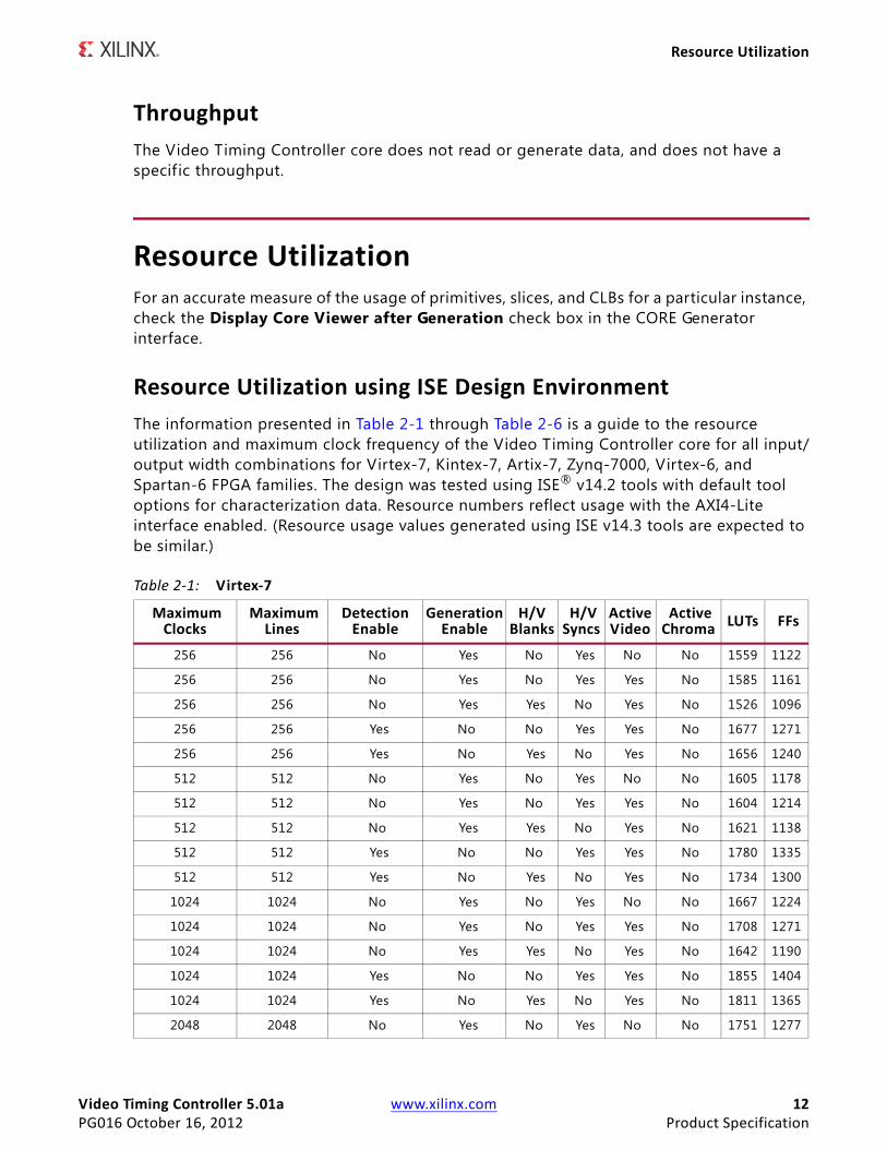
Resource UtilizationFor an accurate measure of the usage of primitives, slices, and CLBs for a particular instance, check the Display Core Viewer after Generation check box in the CORE Generator interface.
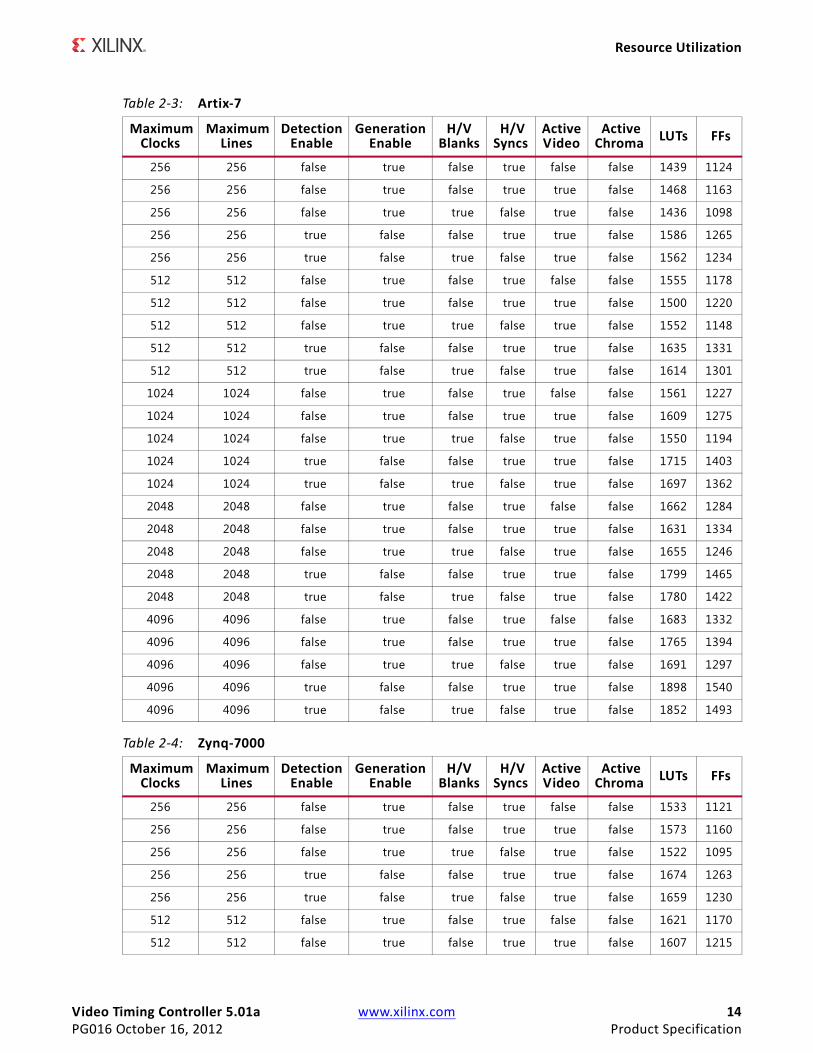
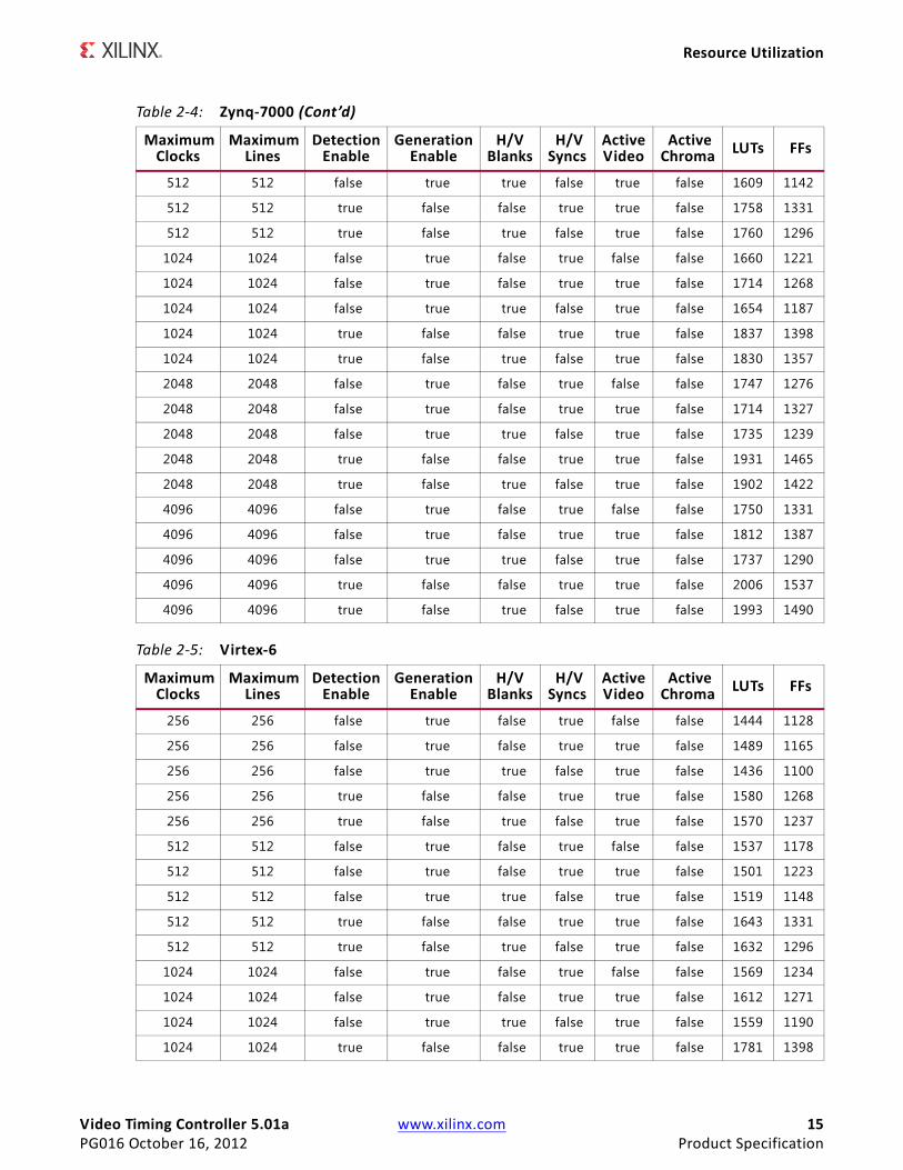
Resource Utilization using ISE Design EnvironmentThe information presented in Table 2-1 through Table 2-6 is a guide to the resource utilization and maximum clock frequency of the Video Timing Controller core for all input/output width combinations for Virtex-7, Kintex-7, Artix-7, Zynq-7000, Virtex-6, and Spartan-6 FPGA families. The design was tested using ISE® v14.2 tools with default tool options for characterization data. Resource numbers reflect usage with the AXI4-Lite interface enabled. (Resource usage values generated using ISE v14.3 tools are expected to be similar.)
Table 2-1: Virtex-7
Maximum Clocks
Maximum Lines
Detection Enable
Generation Enable
H/V Blanks
H/V Syncs
Active Video
Active Chroma LUTs FFs
256 256 No Yes No Yes No No 1559 1122
256 256 No Yes No Yes Yes No 1585 1161
256 256 No Yes Yes No Yes No 1526 1096
256 256 Yes No No Yes Yes No 1677 1271
256 256 Yes No Yes No Yes No 1656 1240
512 512 No Yes No Yes No No 1605 1178
512 512 No Yes No Yes Yes No 1604 1214
512 512 No Yes Yes No Yes No 1621 1138
512 512 Yes No No Yes Yes No 1780 1335
512 512 Yes No Yes No Yes No 1734 1300
1024 1024 No Yes No Yes No No 1667 1224
1024 1024 No Yes No Yes Yes No 1708 1271
1024 1024 No Yes Yes No Yes No 1642 1190
1024 1024 Yes No No Yes Yes No 1855 1404
1024 1024 Yes No Yes No Yes No 1811 1365
2048 2048 No Yes No Yes No No 1751 1277
Video Timing Controller 5.01a www.xilinx.com 13PG016 October 16, 2012 Product Specification
Resource Utilization
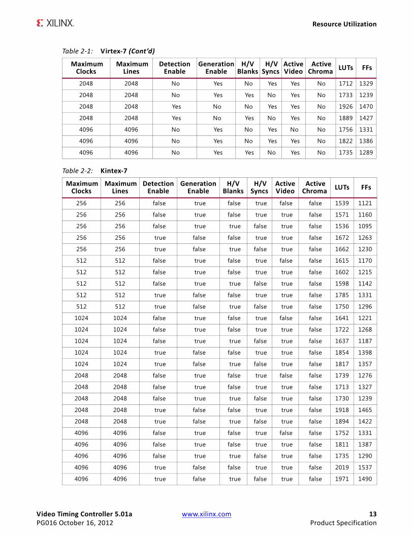
2048 2048 No Yes No Yes Yes No 1712 1329
2048 2048 No Yes Yes No Yes No 1733 1239
2048 2048 Yes No No Yes Yes No 1926 1470
2048 2048 Yes No Yes No Yes No 1889 1427
4096 4096 No Yes No Yes No No 1756 1331
4096 4096 No Yes No Yes Yes No 1822 1386
4096 4096 No Yes Yes No Yes No 1735 1289
Table 2-2: Kintex-7
Maximum Clocks
Maximum Lines
Detection Enable
Generation Enable
H/V Blanks
H/V Syncs
Active Video
Active Chroma LUTs FFs
256 256 false true false true false false 1539 1121
256 256 false true false true true false 1571 1160
256 256 false true true false true false 1536 1095
256 256 true false false true true false 1672 1263
256 256 true false true false true false 1662 1230
512 512 false true false true false false 1615 1170
512 512 false true false true true false 1602 1215
512 512 false true true false true false 1598 1142
512 512 true false false true true false 1785 1331
512 512 true false true false true false 1750 1296
1024 1024 false true false true false false 1641 1221
1024 1024 false true false true true false 1722 1268
1024 1024 false true true false true false 1637 1187
1024 1024 true false false true true false 1854 1398
1024 1024 true false true false true false 1817 1357
2048 2048 false true false true false false 1739 1276
2048 2048 false true false true true false 1713 1327
2048 2048 false true true false true false 1730 1239
2048 2048 true false false true true false 1918 1465
2048 2048 true false true false true false 1894 1422
4096 4096 false true false true false false 1752 1331
4096 4096 false true false true true false 1811 1387
4096 4096 false true true false true false 1735 1290
4096 4096 true false false true true false 2019 1537
4096 4096 true false true false true false 1971 1490
Table 2-1: Virtex-7 (Cont’d)
Maximum Clocks
Maximum Lines
Detection Enable
Generation Enable
H/V Blanks
H/V Syncs
Active Video
Active Chroma LUTs FFs
Video Timing Controller 5.01a www.xilinx.com 14PG016 October 16, 2012 Product Specification
Resource Utilization
Table 2-3: Artix-7
Maximum Clocks
Maximum Lines
Detection Enable
Generation Enable
H/V Blanks
H/V Syncs
Active Video
Active Chroma LUTs FFs
256 256 false true false true false false 1439 1124
256 256 false true false true true false 1468 1163
256 256 false true true false true false 1436 1098
256 256 true false false true true false 1586 1265
256 256 true false true false true false 1562 1234
512 512 false true false true false false 1555 1178
512 512 false true false true true false 1500 1220
512 512 false true true false true false 1552 1148
512 512 true false false true true false 1635 1331
512 512 true false true false true false 1614 1301
1024 1024 false true false true false false 1561 1227
1024 1024 false true false true true false 1609 1275
1024 1024 false true true false true false 1550 1194
1024 1024 true false false true true false 1715 1403
1024 1024 true false true false true false 1697 1362
2048 2048 false true false true false false 1662 1284
2048 2048 false true false true true false 1631 1334
2048 2048 false true true false true false 1655 1246
2048 2048 true false false true true false 1799 1465
2048 2048 true false true false true false 1780 1422
4096 4096 false true false true false false 1683 1332
4096 4096 false true false true true false 1765 1394
4096 4096 false true true false true false 1691 1297
4096 4096 true false false true true false 1898 1540
4096 4096 true false true false true false 1852 1493
Table 2-4: Zynq-7000
Maximum Clocks
Maximum Lines
Detection Enable
Generation Enable
H/V Blanks
H/V Syncs
Active Video
Active Chroma LUTs FFs
256 256 false true false true false false 1533 1121
256 256 false true false true true false 1573 1160
256 256 false true true false true false 1522 1095
256 256 true false false true true false 1674 1263
256 256 true false true false true false 1659 1230
512 512 false true false true false false 1621 1170
512 512 false true false true true false 1607 1215
Video Timing Controller 5.01a www.xilinx.com 15PG016 October 16, 2012 Product Specification
Resource Utilization
512 512 false true true false true false 1609 1142
512 512 true false false true true false 1758 1331
512 512 true false true false true false 1760 1296
1024 1024 false true false true false false 1660 1221
1024 1024 false true false true true false 1714 1268
1024 1024 false true true false true false 1654 1187
1024 1024 true false false true true false 1837 1398
1024 1024 true false true false true false 1830 1357
2048 2048 false true false true false false 1747 1276
2048 2048 false true false true true false 1714 1327
2048 2048 false true true false true false 1735 1239
2048 2048 true false false true true false 1931 1465
2048 2048 true false true false true false 1902 1422
4096 4096 false true false true false false 1750 1331
4096 4096 false true false true true false 1812 1387
4096 4096 false true true false true false 1737 1290
4096 4096 true false false true true false 2006 1537
4096 4096 true false true false true false 1993 1490
Table 2-5: Virtex-6
Maximum Clocks
Maximum Lines
Detection Enable
Generation Enable
H/V Blanks
H/V Syncs
Active Video
Active Chroma LUTs FFs
256 256 false true false true false false 1444 1128
256 256 false true false true true false 1489 1165
256 256 false true true false true false 1436 1100
256 256 true false false true true false 1580 1268
256 256 true false true false true false 1570 1237
512 512 false true false true false false 1537 1178
512 512 false true false true true false 1501 1223
512 512 false true true false true false 1519 1148
512 512 true false false true true false 1643 1331
512 512 true false true false true false 1632 1296
1024 1024 false true false true false false 1569 1234
1024 1024 false true false true true false 1612 1271
1024 1024 false true true false true false 1559 1190
1024 1024 true false false true true false 1781 1398
Table 2-4: Zynq-7000 (Cont’d)
Maximum Clocks
Maximum Lines
Detection Enable
Generation Enable
H/V Blanks
H/V Syncs
Active Video
Active Chroma LUTs FFs
Video Timing Controller 5.01a www.xilinx.com 16PG016 October 16, 2012 Product Specification
Resource Utilization
1024 1024 true false true false true false 1746 1360
2048 2048 false true false true false false 1650 1286
2048 2048 false true false true true false 1617 1327
2048 2048 false true true false true false 1636 1248
2048 2048 true false false true true false 1825 1470
2048 2048 true false true false true false 1795 1427
4096 4096 false true false true false false 1650 1336
4096 4096 false true false true true false 1713 1391
4096 4096 false true true false true false 1627 1294
4096 4096 true false false true true false 1906 1536
4096 4096 true false true false true false 1897 1489
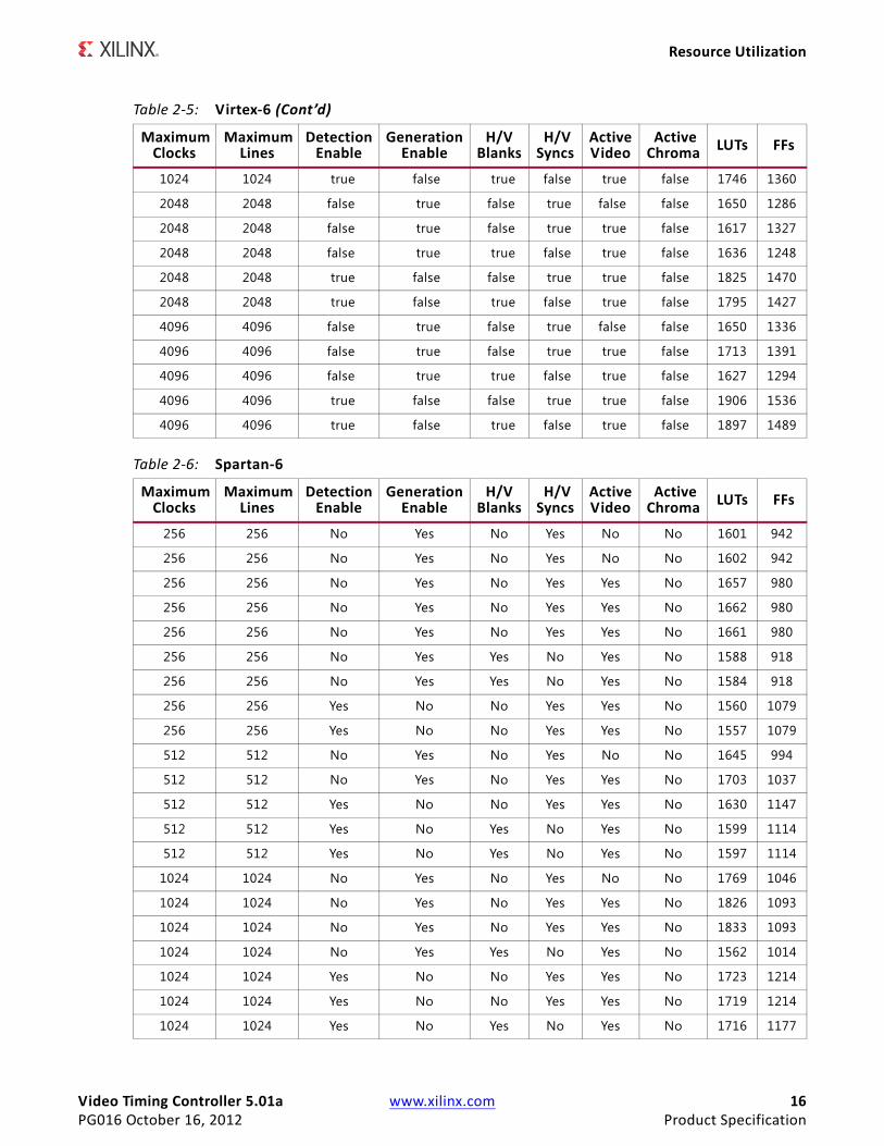
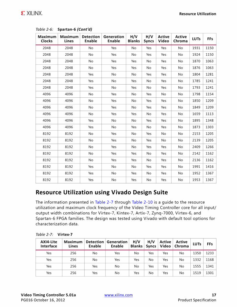
Table 2-6: Spartan-6
Maximum Clocks
Maximum Lines
Detection Enable
Generation Enable
H/V Blanks
H/V Syncs
Active Video
Active Chroma LUTs FFs
256 256 No Yes No Yes No No 1601 942
256 256 No Yes No Yes No No 1602 942
256 256 No Yes No Yes Yes No 1657 980
256 256 No Yes No Yes Yes No 1662 980
256 256 No Yes No Yes Yes No 1661 980
256 256 No Yes Yes No Yes No 1588 918
256 256 No Yes Yes No Yes No 1584 918
256 256 Yes No No Yes Yes No 1560 1079
256 256 Yes No No Yes Yes No 1557 1079
512 512 No Yes No Yes No No 1645 994
512 512 No Yes No Yes Yes No 1703 1037
512 512 Yes No No Yes Yes No 1630 1147
512 512 Yes No Yes No Yes No 1599 1114
512 512 Yes No Yes No Yes No 1597 1114
1024 1024 No Yes No Yes No No 1769 1046
1024 1024 No Yes No Yes Yes No 1826 1093
1024 1024 No Yes No Yes Yes No 1833 1093
1024 1024 No Yes Yes No Yes No 1562 1014
1024 1024 Yes No No Yes Yes No 1723 1214
1024 1024 Yes No No Yes Yes No 1719 1214
1024 1024 Yes No Yes No Yes No 1716 1177
Table 2-5: Virtex-6 (Cont’d)
Maximum Clocks
Maximum Lines
Detection Enable
Generation Enable
H/V Blanks
H/V Syncs
Active Video
Active Chroma LUTs FFs
Video Timing Controller 5.01a www.xilinx.com 17PG016 October 16, 2012 Product Specification
Resource Utilization
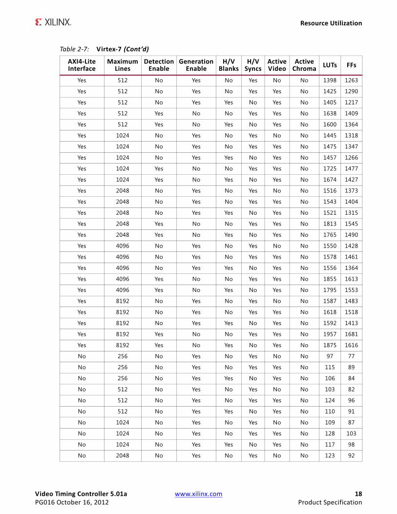
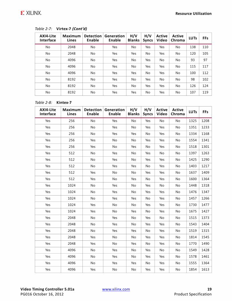
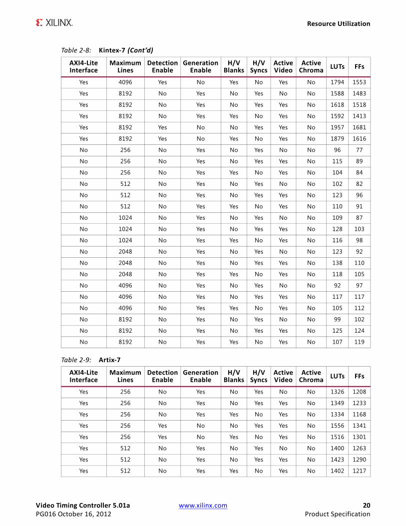
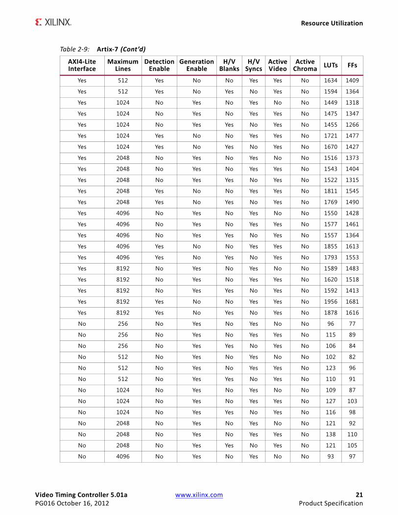
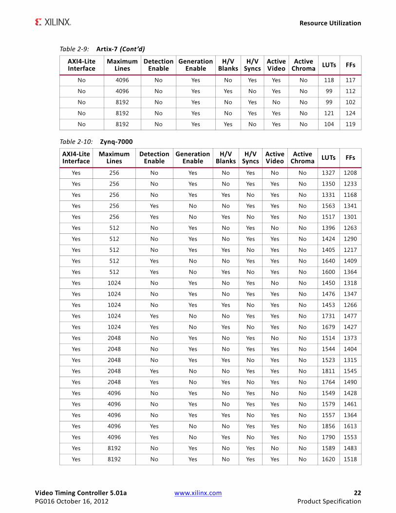
Resource Utilization using Vivado Design SuiteThe information presented in Table 2-7 through Table 2-10 is a guide to the resource utilization and maximum clock frequency of the Video Timing Controller core for all input/output width combinations for Virtex-7, Kintex-7, Artix-7, Zynq-7000, Virtex-6, and Spartan-6 FPGA families. The design was tested using Vivado with default tool options for characterization data.
2048 2048 No Yes No Yes Yes No 1931 1150
2048 2048 No Yes No Yes Yes No 1924 1150
2048 2048 No Yes Yes No Yes No 1870 1063
2048 2048 No Yes Yes No Yes No 1876 1063
2048 2048 Yes No No Yes Yes No 1804 1281
2048 2048 Yes No Yes No Yes No 1785 1241
2048 2048 Yes No Yes No Yes No 1793 1241
4096 4096 No Yes No Yes No No 1798 1154
4096 4096 No Yes No Yes Yes No 1850 1209
4096 4096 No Yes No Yes Yes No 1849 1209
4096 4096 No Yes Yes No Yes No 1659 1113
4096 4096 Yes No No Yes Yes No 1895 1348
4096 4096 Yes No Yes No Yes No 1873 1303
8192 8192 No Yes No Yes No No 2153 1205
8192 8192 No Yes No Yes No No 2139 1205
8192 8192 No Yes No Yes Yes No 2409 1266
8192 8192 No Yes Yes No Yes No 2142 1162
8192 8192 No Yes Yes No Yes No 2136 1162
8192 8192 Yes No No Yes Yes No 1991 1416
8192 8192 Yes No Yes No Yes No 1952 1367
8192 8192 Yes No Yes No Yes No 1953 1367
Table 2-7: Virtex-7
AXI4-LiteInterface
MaximumLines
Detection Enable
GenerationEnable
H/V Blanks
H/V Syncs
Active Video
Active Chroma LUTs FFs
Yes 256 No Yes No Yes Yes No 1350 1233
Yes 256 No Yes Yes No Yes No 1332 1168
Yes 256 Yes No No Yes Yes No 1555 1341
Yes 256 Yes No Yes No Yes No 1519 1301
Table 2-6: Spartan-6 (Cont’d)
Maximum Clocks
Maximum Lines
Detection Enable
Generation Enable
H/V Blanks
H/V Syncs
Active Video
Active Chroma LUTs FFs
Video Timing Controller 5.01a www.xilinx.com 18PG016 October 16, 2012 Product Specification
Resource Utilization
Yes 512 No Yes No Yes No No 1398 1263
Yes 512 No Yes No Yes Yes No 1425 1290
Yes 512 No Yes Yes No Yes No 1405 1217
Yes 512 Yes No No Yes Yes No 1638 1409
Yes 512 Yes No Yes No Yes No 1600 1364
Yes 1024 No Yes No Yes No No 1445 1318
Yes 1024 No Yes No Yes Yes No 1475 1347
Yes 1024 No Yes Yes No Yes No 1457 1266
Yes 1024 Yes No No Yes Yes No 1725 1477
Yes 1024 Yes No Yes No Yes No 1674 1427
Yes 2048 No Yes No Yes No No 1516 1373
Yes 2048 No Yes No Yes Yes No 1543 1404
Yes 2048 No Yes Yes No Yes No 1521 1315
Yes 2048 Yes No No Yes Yes No 1813 1545
Yes 2048 Yes No Yes No Yes No 1765 1490
Yes 4096 No Yes No Yes No No 1550 1428
Yes 4096 No Yes No Yes Yes No 1578 1461
Yes 4096 No Yes Yes No Yes No 1556 1364
Yes 4096 Yes No No Yes Yes No 1855 1613
Yes 4096 Yes No Yes No Yes No 1795 1553
Yes 8192 No Yes No Yes No No 1587 1483
Yes 8192 No Yes No Yes Yes No 1618 1518
Yes 8192 No Yes Yes No Yes No 1592 1413
Yes 8192 Yes No No Yes Yes No 1957 1681
Yes 8192 Yes No Yes No Yes No 1875 1616
No 256 No Yes No Yes No No 97 77
No 256 No Yes No Yes Yes No 115 89
No 256 No Yes Yes No Yes No 106 84
No 512 No Yes No Yes No No 103 82
No 512 No Yes No Yes Yes No 124 96
No 512 No Yes Yes No Yes No 110 91
No 1024 No Yes No Yes No No 109 87
No 1024 No Yes No Yes Yes No 128 103
No 1024 No Yes Yes No Yes No 117 98
No 2048 No Yes No Yes No No 123 92
Table 2-7: Virtex-7 (Cont’d)
AXI4-LiteInterface
MaximumLines
Detection Enable
GenerationEnable
H/V Blanks
H/V Syncs
Active Video
Active Chroma LUTs FFs
Video Timing Controller 5.01a www.xilinx.com 19PG016 October 16, 2012 Product Specification
Resource Utilization
No 2048 No Yes No Yes Yes No 138 110
No 2048 No Yes Yes No Yes No 120 105
No 4096 No Yes No Yes No No 93 97
No 4096 No Yes No Yes Yes No 115 117
No 4096 No Yes Yes No Yes No 100 112
No 8192 No Yes No Yes No No 98 102
No 8192 No Yes No Yes Yes No 126 124
No 8192 No Yes Yes No Yes No 107 119
Table 2-8: Kintex-7
AXI4-LiteInterface
MaximumLines
Detection Enable
GenerationEnable
H/V Blanks
H/V Syncs
Active Video
Active Chroma LUTs FFs
Yes 256 No Yes No Yes No No 1325 1208
Yes 256 No Yes No Yes Yes No 1351 1233
Yes 256 No Yes Yes No Yes No 1334 1168
Yes 256 Yes No No Yes Yes No 1554 1341
Yes 256 Yes No Yes No Yes No 1518 1301
Yes 512 No Yes No Yes No No 1397 1263
Yes 512 No Yes No Yes Yes No 1425 1290
Yes 512 No Yes Yes No Yes No 1403 1217
Yes 512 Yes No No Yes Yes No 1637 1409
Yes 512 Yes No Yes No Yes No 1600 1364
Yes 1024 No Yes No Yes No No 1448 1318
Yes 1024 No Yes No Yes Yes No 1476 1347
Yes 1024 No Yes Yes No Yes No 1457 1266
Yes 1024 Yes No No Yes Yes No 1730 1477
Yes 1024 Yes No Yes No Yes No 1675 1427
Yes 2048 No Yes No Yes No No 1515 1373
Yes 2048 No Yes No Yes Yes No 1543 1404
Yes 2048 No Yes Yes No Yes No 1519 1315
Yes 2048 Yes No No Yes Yes No 1814 1545
Yes 2048 Yes No Yes No Yes No 1770 1490
Yes 4096 No Yes No Yes No No 1549 1428
Yes 4096 No Yes No Yes Yes No 1578 1461
Yes 4096 No Yes Yes No Yes No 1555 1364
Yes 4096 Yes No No Yes Yes No 1854 1613
Table 2-7: Virtex-7 (Cont’d)
AXI4-LiteInterface
MaximumLines
Detection Enable
GenerationEnable
H/V Blanks
H/V Syncs
Active Video
Active Chroma LUTs FFs
Video Timing Controller 5.01a www.xilinx.com 20PG016 October 16, 2012 Product Specification
Resource Utilization
Yes 4096 Yes No Yes No Yes No 1794 1553
Yes 8192 No Yes No Yes No No 1588 1483
Yes 8192 No Yes No Yes Yes No 1618 1518
Yes 8192 No Yes Yes No Yes No 1592 1413
Yes 8192 Yes No No Yes Yes No 1957 1681
Yes 8192 Yes No Yes No Yes No 1879 1616
No 256 No Yes No Yes No No 96 77
No 256 No Yes No Yes Yes No 115 89
No 256 No Yes Yes No Yes No 104 84
No 512 No Yes No Yes No No 102 82
No 512 No Yes No Yes Yes No 123 96
No 512 No Yes Yes No Yes No 110 91
No 1024 No Yes No Yes No No 109 87
No 1024 No Yes No Yes Yes No 128 103
No 1024 No Yes Yes No Yes No 116 98
No 2048 No Yes No Yes No No 123 92
No 2048 No Yes No Yes Yes No 138 110
No 2048 No Yes Yes No Yes No 118 105
No 4096 No Yes No Yes No No 92 97
No 4096 No Yes No Yes Yes No 117 117
No 4096 No Yes Yes No Yes No 105 112
No 8192 No Yes No Yes No No 99 102
No 8192 No Yes No Yes Yes No 125 124
No 8192 No Yes Yes No Yes No 107 119
Table 2-9: Artix-7
AXI4-LiteInterface
MaximumLines
Detection Enable
GenerationEnable
H/V Blanks
H/V Syncs
Active Video
Active Chroma LUTs FFs
Yes 256 No Yes No Yes No No 1326 1208
Yes 256 No Yes No Yes Yes No 1349 1233
Yes 256 No Yes Yes No Yes No 1334 1168
Yes 256 Yes No No Yes Yes No 1556 1341
Yes 256 Yes No Yes No Yes No 1516 1301
Yes 512 No Yes No Yes No No 1400 1263
Yes 512 No Yes No Yes Yes No 1423 1290
Yes 512 No Yes Yes No Yes No 1402 1217
Table 2-8: Kintex-7 (Cont’d)
AXI4-LiteInterface
MaximumLines
Detection Enable
GenerationEnable
H/V Blanks
H/V Syncs
Active Video
Active Chroma LUTs FFs
Video Timing Controller 5.01a www.xilinx.com 21PG016 October 16, 2012 Product Specification
Resource Utilization
Yes 512 Yes No No Yes Yes No 1634 1409
Yes 512 Yes No Yes No Yes No 1594 1364
Yes 1024 No Yes No Yes No No 1449 1318
Yes 1024 No Yes No Yes Yes No 1475 1347
Yes 1024 No Yes Yes No Yes No 1455 1266
Yes 1024 Yes No No Yes Yes No 1721 1477
Yes 1024 Yes No Yes No Yes No 1670 1427
Yes 2048 No Yes No Yes No No 1516 1373
Yes 2048 No Yes No Yes Yes No 1543 1404
Yes 2048 No Yes Yes No Yes No 1522 1315
Yes 2048 Yes No No Yes Yes No 1811 1545
Yes 2048 Yes No Yes No Yes No 1769 1490
Yes 4096 No Yes No Yes No No 1550 1428
Yes 4096 No Yes No Yes Yes No 1577 1461
Yes 4096 No Yes Yes No Yes No 1557 1364
Yes 4096 Yes No No Yes Yes No 1855 1613
Yes 4096 Yes No Yes No Yes No 1793 1553
Yes 8192 No Yes No Yes No No 1589 1483
Yes 8192 No Yes No Yes Yes No 1620 1518
Yes 8192 No Yes Yes No Yes No 1592 1413
Yes 8192 Yes No No Yes Yes No 1956 1681
Yes 8192 Yes No Yes No Yes No 1878 1616
No 256 No Yes No Yes No No 96 77
No 256 No Yes No Yes Yes No 115 89
No 256 No Yes Yes No Yes No 106 84
No 512 No Yes No Yes No No 102 82
No 512 No Yes No Yes Yes No 123 96
No 512 No Yes Yes No Yes No 110 91
No 1024 No Yes No Yes No No 109 87
No 1024 No Yes No Yes Yes No 127 103
No 1024 No Yes Yes No Yes No 116 98
No 2048 No Yes No Yes No No 121 92
No 2048 No Yes No Yes Yes No 138 110
No 2048 No Yes Yes No Yes No 121 105
No 4096 No Yes No Yes No No 93 97
Table 2-9: Artix-7 (Cont’d)
AXI4-LiteInterface
MaximumLines
Detection Enable
GenerationEnable
H/V Blanks
H/V Syncs
Active Video
Active Chroma LUTs FFs
Video Timing Controller 5.01a www.xilinx.com 22PG016 October 16, 2012 Product Specification
Resource Utilization
No 4096 No Yes No Yes Yes No 118 117
No 4096 No Yes Yes No Yes No 99 112
No 8192 No Yes No Yes No No 99 102
No 8192 No Yes No Yes Yes No 121 124
No 8192 No Yes Yes No Yes No 104 119
Table 2-10: Zynq-7000
AXI4-LiteInterface
MaximumLines
Detection Enable
GenerationEnable
H/V Blanks
H/V Syncs
Active Video
Active Chroma LUTs FFs
Yes 256 No Yes No Yes No No 1327 1208
Yes 256 No Yes No Yes Yes No 1350 1233
Yes 256 No Yes Yes No Yes No 1331 1168
Yes 256 Yes No No Yes Yes No 1563 1341
Yes 256 Yes No Yes No Yes No 1517 1301
Yes 512 No Yes No Yes No No 1396 1263
Yes 512 No Yes No Yes Yes No 1424 1290
Yes 512 No Yes Yes No Yes No 1405 1217
Yes 512 Yes No No Yes Yes No 1640 1409
Yes 512 Yes No Yes No Yes No 1600 1364
Yes 1024 No Yes No Yes No No 1450 1318
Yes 1024 No Yes No Yes Yes No 1476 1347
Yes 1024 No Yes Yes No Yes No 1453 1266
Yes 1024 Yes No No Yes Yes No 1731 1477
Yes 1024 Yes No Yes No Yes No 1679 1427
Yes 2048 No Yes No Yes No No 1514 1373
Yes 2048 No Yes No Yes Yes No 1544 1404
Yes 2048 No Yes Yes No Yes No 1523 1315
Yes 2048 Yes No No Yes Yes No 1811 1545
Yes 2048 Yes No Yes No Yes No 1764 1490
Yes 4096 No Yes No Yes No No 1549 1428
Yes 4096 No Yes No Yes Yes No 1579 1461
Yes 4096 No Yes Yes No Yes No 1557 1364
Yes 4096 Yes No No Yes Yes No 1856 1613
Yes 4096 Yes No Yes No Yes No 1790 1553
Yes 8192 No Yes No Yes No No 1589 1483
Yes 8192 No Yes No Yes Yes No 1620 1518
Table 2-9: Artix-7 (Cont’d)
AXI4-LiteInterface
MaximumLines
Detection Enable
GenerationEnable
H/V Blanks
H/V Syncs
Active Video
Active Chroma LUTs FFs
Video Timing Controller 5.01a www.xilinx.com 23PG016 October 16, 2012 Product Specification
Core Interfaces and Register Space
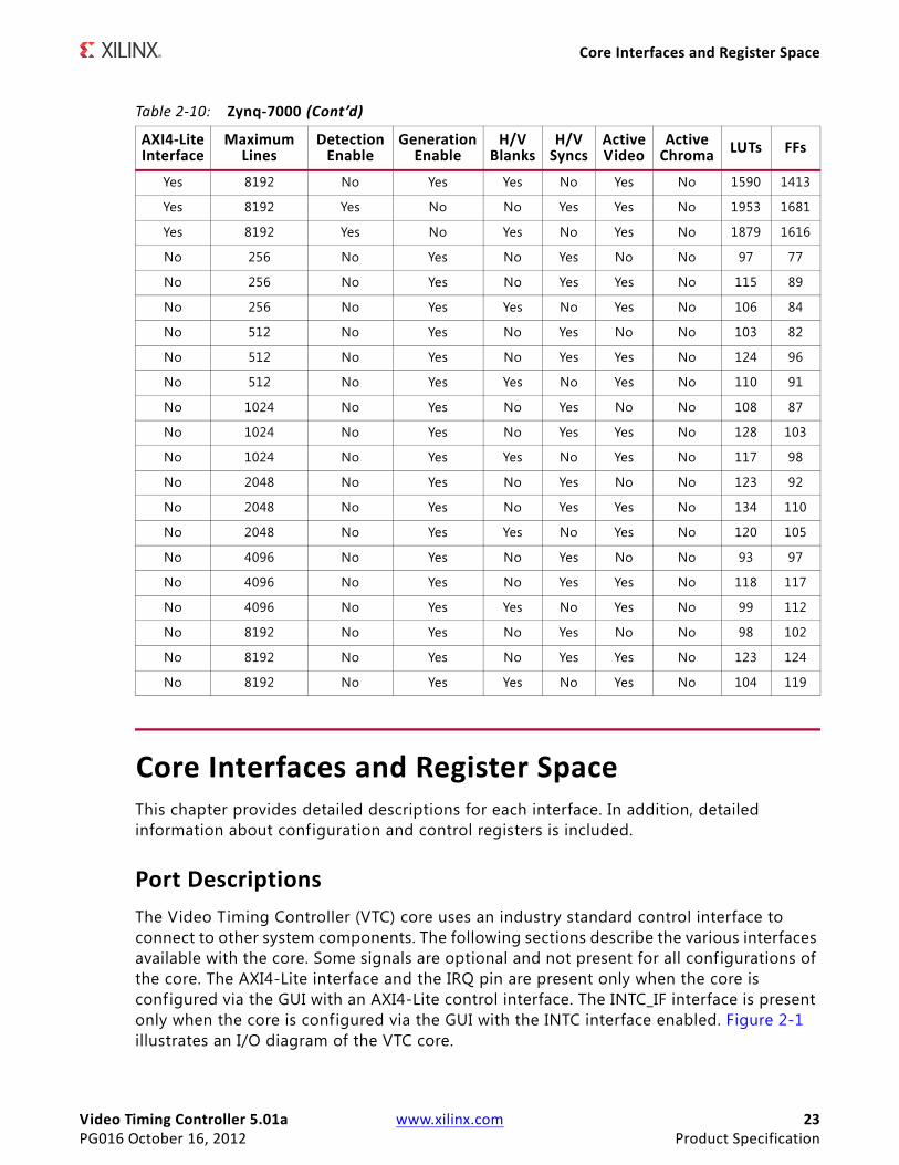
Core Interfaces and Register SpaceThis chapter provides detailed descriptions for each interface. In addition, detailed information about configuration and control registers is included.
Port DescriptionsThe Video Timing Controller (VTC) core uses an industry standard control interface to connect to other system components. The following sections describe the various interfaces available with the core. Some signals are optional and not present for all configurations of the core. The AXI4-Lite interface and the IRQ pin are present only when the core is configured via the GUI with an AXI4-Lite control interface. The INTC_IF interface is present only when the core is configured via the GUI with the INTC interface enabled. Figure 2-1 illustrates an I/O diagram of the VTC core.
Yes 8192 No Yes Yes No Yes No 1590 1413
Yes 8192 Yes No No Yes Yes No 1953 1681
Yes 8192 Yes No Yes No Yes No 1879 1616
No 256 No Yes No Yes No No 97 77
No 256 No Yes No Yes Yes No 115 89
No 256 No Yes Yes No Yes No 106 84
No 512 No Yes No Yes No No 103 82
No 512 No Yes No Yes Yes No 124 96
No 512 No Yes Yes No Yes No 110 91
No 1024 No Yes No Yes No No 108 87
No 1024 No Yes No Yes Yes No 128 103
No 1024 No Yes Yes No Yes No 117 98
No 2048 No Yes No Yes No No 123 92
No 2048 No Yes No Yes Yes No 134 110
No 2048 No Yes Yes No Yes No 120 105
No 4096 No Yes No Yes No No 93 97
No 4096 No Yes No Yes Yes No 118 117
No 4096 No Yes Yes No Yes No 99 112
No 8192 No Yes No Yes No No 98 102
No 8192 No Yes No Yes Yes No 123 124
No 8192 No Yes Yes No Yes No 104 119
Table 2-10: Zynq-7000 (Cont’d)
AXI4-LiteInterface
MaximumLines
Detection Enable
GenerationEnable
H/V Blanks
H/V Syncs
Active Video
Active Chroma LUTs FFs
Video Timing Controller 5.01a www.xilinx.com 24PG016 October 16, 2012 Product Specification
Core Interfaces and Register Space
Core Interfaces
Control Interface
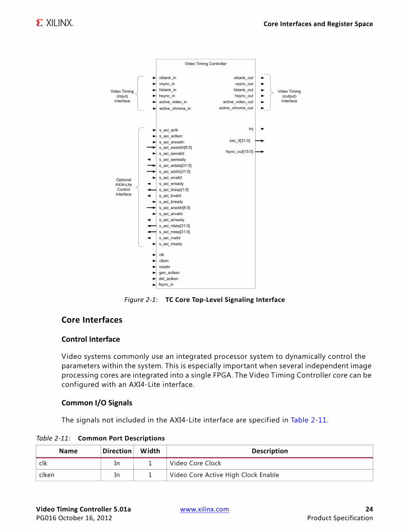
Video systems commonly use an integrated processor system to dynamically control the parameters within the system. This is especially important when several independent image processing cores are integrated into a single FPGA. The Video Timing Controller core can be configured with an AXI4-Lite interface.
Common I/O Signals
The signals not included in the AXI4-Lite interface are specif ied in Table 2-11.
X-Ref Target - Figure 2-1
Figure 2-1: TC Core Top-Level Signaling Interface
Video Timing Controller
vblank_invsync_inhblank_inhsync_in
vblank_outvsync_out
hblank_outhsync_out
active_video_out
Video Timing (input)
Interface
OptionalAXI4-LiteControl
Interface
Video Timing (output)Interfaceactive_video_in
clkclkenresetn
s_axi_awaddr[8:0]s_axi_awvalids_axi_awreadys_axi_wdata[31:0]s_axi_wstrb[31:0]s_axi_wvalids_axi_wreadys_axi_bresp[1:0]s_axi_bvalids_axi_breadys_axi_araddr[8:0]s_axi_arvalids_axi_arreadys_axi_rdata[31:0]s_axi_rresp[31:0]s_axi_rvalids_axi_rready
intc_if[31:0]
irq
gen_aclkendet_aclken
fsync_out[15:0]
fsync_in
active_chroma_outactive_chroma_in
s_axi_aclks_axi_aclkens_axi_aresetn
Table 2-11: Common Port Descriptions
Name Direction Width Description
clk In 1 Video Core Clock
clken In 1 Video Core Active High Clock Enable
Video Timing Controller 5.01a www.xilinx.com 25PG016 October 16, 2012 Product Specification
Core Interfaces and Register Space
det_clken In 1 Video Timing Detection Core Active High Clock Enable
gen_clken In 1 Video Timing Generator Core Active High Clock Enable
resetn In 1 Video Core Active Low Synchronous Reset
irq Output 1 Interrupt request output, active high edge
intc_if Output 32 OPTIONAL EXTERNAL INTERRUPT CONTROLLER INTERFACEAvailable when the "Include INTC Interface" or C_HAS_INTC_IF has been selected. Bits [31:8] are the same as the bits [31:8] in the status register (0x0004). Bits [5:0] are the same as bits [21:16] of the error register (0x0008). Bits [7:6] are reserved and are always 0.
Detector Interface (Video Timing Input Interface)
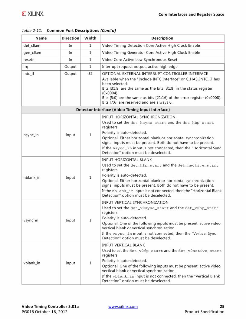
hsync_in Input 1
INPUT HORIZONTAL SYNCHRONIZATIONUsed to set the det_hsync_start and the det_hbp_start registers.Polarity is auto-detected.Optional. Either horizontal blank or horizontal synchronization signal inputs must be present. Both do not have to be present.If the hsync_in input is not connected, then the "Horizontal Sync Detection" option must be deselected.
hblank_in Input 1
INPUT HORIZONTAL BLANK Used to set the det_hfp_start and the det_hactive_start registers.Polarity is auto-detected. Optional. Either horizontal blank or horizontal synchronization signal inputs must be present. Both do not have to be present.If the hblank_in input is not connected, then the "Horizontal Blank Detection" option must be deselected.
vsync_in Input 1
INPUT VERTICAL SYNCHRONIZATIONUsed to set the det_v0sync_start and the det_v0bp_start registers.Polarity is auto-detected.Optional. One of the following inputs must be present: active video, vertical blank or vertical synchronization. If the vsync_in input is not connected, then the "Vertical Sync Detection" option must be deselected.
vblank_in Input 1
INPUT VERTICAL BLANKUsed to set the det_v0fp_start and the det_v0active_start registers.Polarity is auto-detected.Optional. One of the following inputs must be present: active video, vertical blank or vertical synchronization.If the vblank_in input is not connected, then the "Vertical Blank Detection" option must be deselected.
Table 2-11: Common Port Descriptions (Cont’d)
Name Direction Width Description
Video Timing Controller 5.01a www.xilinx.com 26PG016 October 16, 2012 Product Specification
Core Interfaces and Register Space
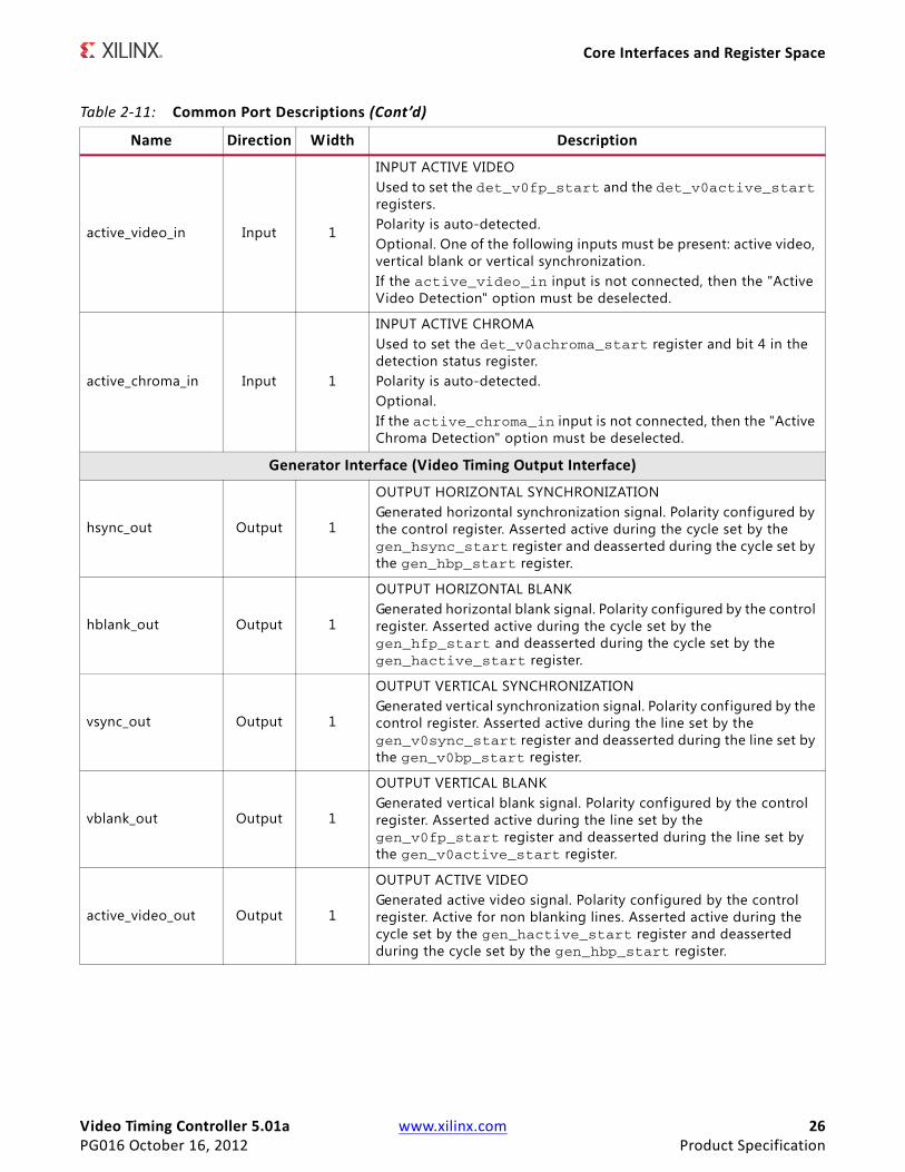
active_video_in Input 1
INPUT ACTIVE VIDEOUsed to set the det_v0fp_start and the det_v0active_start registers.Polarity is auto-detected.Optional. One of the following inputs must be present: active video, vertical blank or vertical synchronization.If the active_video_in input is not connected, then the "Active Video Detection" option must be deselected.
active_chroma_in Input 1
INPUT ACTIVE CHROMAUsed to set the det_v0achroma_start register and bit 4 in the detection status register.Polarity is auto-detected.Optional.If the active_chroma_in input is not connected, then the "Active Chroma Detection" option must be deselected.
Generator Interface (Video Timing Output Interface)
hsync_out Output 1
OUTPUT HORIZONTAL SYNCHRONIZATIONGenerated horizontal synchronization signal. Polarity configured by the control register. Asserted active during the cycle set by the gen_hsync_start register and deasserted during the cycle set by the gen_hbp_start register.
hblank_out Output 1
OUTPUT HORIZONTAL BLANKGenerated horizontal blank signal. Polarity configured by the control register. Asserted active during the cycle set by the gen_hfp_start and deasserted during the cycle set by the gen_hactive_start register.
vsync_out Output 1
OUTPUT VERTICAL SYNCHRONIZATIONGenerated vertical synchronization signal. Polarity configured by the control register. Asserted active during the line set by the gen_v0sync_start register and deasserted during the line set by the gen_v0bp_start register.
vblank_out Output 1
OUTPUT VERTICAL BLANKGenerated vertical blank signal. Polarity configured by the control register. Asserted active during the line set by the gen_v0fp_start register and deasserted during the line set by the gen_v0active_start register.
active_video_out Output 1
OUTPUT ACTIVE VIDEOGenerated active video signal. Polarity configured by the control register. Active for non blanking lines. Asserted active during the cycle set by the gen_hactive_start register and deasserted during the cycle set by the gen_hbp_start register.
Table 2-11: Common Port Descriptions (Cont’d)
Name Direction Width Description
Video Timing Controller 5.01a www.xilinx.com 27PG016 October 16, 2012 Product Specification
Core Interfaces and Register Space
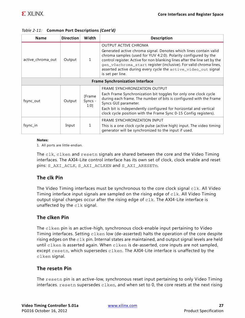
Notes: 1. All ports are little-endian.
The clk , clken and resetn signals are shared between the core and the Video Timing interfaces. The AXI4-Lite control interface has its own set of clock, clock enable and reset pins: S_AXI_ACLK, S_AXI_ACLKEN and S_AXI_ARESETn.
The clk Pin
The Video Timing interfaces must be synchronous to the core clock signal clk . All Video Timing interface input signals are sampled on the rising edge of clk . All Video Timing output signal changes occur after the rising edge of clk . The AXI4-Lite interface is unaffected by the clk signal.
The clken Pin
The clken pin is an active-high, synchronous clock-enable input pertaining to Video Timing interfaces. Setting clken low (de-asserted) halts the operation of the core despite rising edges on the clk pin. Internal states are maintained, and output signal levels are held until clken is asserted again. When clken is de-asserted, core inputs are not sampled, except resetn, which supersedes clken. The AXI4-Lite interface is unaffected by the clken signal.
The resetn Pin
The resetn pin is an active-low, synchronous reset input pertaining to only Video Timing interfaces. resetn supersedes clken, and when set to 0, the core resets at the next rising
active_chroma_out Output 1
OUTPUT ACTIVE CHROMAGenerated active chroma signal. Denotes which lines contain valid chroma samples (used for YUV 4:2:0). Polarity configured by the control register. Active for non blanking lines after the line set by the gen_v0achroma_start register (inclusive). For valid chroma lines, asserted active during every cycle the active_video_out signal is set per line.
Frame Synchronization Interface
fsync_out Output[Frame Syncs -
1:0]
FRAME SYNCHRONIZATION OUTPUTEach Frame Synchronization bit toggles for only one clock cycle during each frame. The number of bits is configured with the Frame Syncs GUI parameter.Each bit is independently configured for horizontal and vertical clock cycle position with the Frame Sync 0-15 Config registers).
fsync_in Input 1FRAME SYNCHRONIZATION INPUTThis is a one clock cycle pulse (active high) input. The video timing generator will be synchronized to the input if used.
Table 2-11: Common Port Descriptions (Cont’d)
Name Direction Width Description
Video Timing Controller 5.01a www.xilinx.com 28PG016 October 16, 2012 Product Specification
Core Interfaces and Register Space
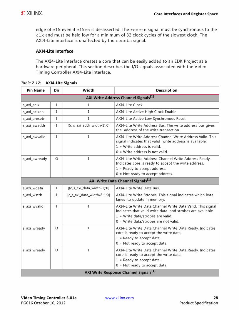
edge of clk even if clken is de-asserted. The resetn signal must be synchronous to the clk and must be held low for a minimum of 32 clock cycles of the slowest clock. The AXI4-Lite interface is unaffected by the resetn signal.
AXI4-Lite Interface
The AXI4-Lite interface creates a core that can be easily added to an EDK Project as a hardware peripheral. This section describes the I/O signals associated with the Video Timing Controller AXI4-Lite interface.
Table 2-12: AXI4-Lite Signals
Pin Name Dir Width Description
AXI Write Address Channel Signals(1)
s_axi_aclk I 1 AXI4-Lite Clock
s_axi_aclken I 1 AXI4-Lite Active High Clock Enable
s_axi_aresetn I 1 AXI4-Lite Active Low Synchronous Reset
s_axi_awaddr I [(c_s_axi_addr_width-1):0] AXI4-Lite Write Address Bus. The write address bus gives the address of the write transaction.
s_axi_awvalid I 1 AXI4-Lite Write Address Channel Write Address Valid. This signal indicates that valid write address is available.1 = Write address is valid.0 = Write address is not valid.
s_axi_awready O 1 AXI4-Lite Write Address Channel Write Address Ready. Indicates core is ready to accept the write address.1 = Ready to accept address.0 = Not ready to accept address.
AXI Write Data Channel Signals(1)
s_axi_wdata I [(c_s_axi_data_width-1):0] AXI4-Lite Write Data Bus.
s_axi_wstrb I [c_s_axi_data_width/8-1:0] AXI4-Lite Write Strobes. This signal indicates which byte lanes to update in memory.
s_axi_wvalid I 1 AXI4-Lite Write Data Channel Write Data Valid. This signal indicates that valid write data and strobes are available.1 = Write data/strobes are valid.0 = Write data/strobes are not valid.
s_axi_wready O 1 AXI4-Lite Write Data Channel Write Data Ready. Indicates core is ready to accept the write data.1 = Ready to accept data.0 = Not ready to accept data.
s_axi_wready O 1 AXI4-Lite Write Data Channel Write Data Ready. Indicates core is ready to accept the write data.1 = Ready to accept data.0 = Not ready to accept data.
AXI Write Response Channel Signals(1)
Video Timing Controller 5.01a www.xilinx.com 29PG016 October 16, 2012 Product Specification
Core Interfaces and Register Space
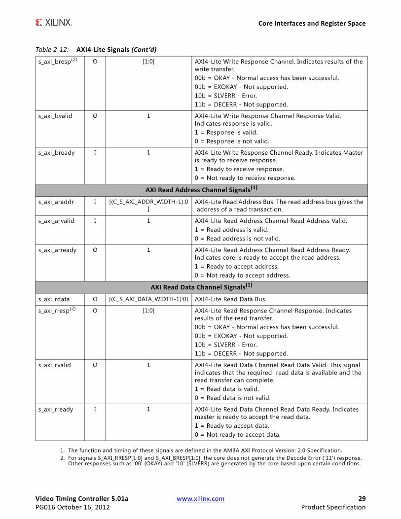
1. The function and timing of these signals are defined in the AMBA AXI Protocol Version: 2.0 Specif ication.2. For signals S_AXI_RRESP[1:0] and S_AXI_BRESP[1:0], the core does not generate the Decode Error ('11') response.
Other responses such as '00' (OKAY) and '10' (SLVERR) are generated by the core based upon certain conditions.
s_axi_bresp(2) O [1:0] AXI4-Lite Write Response Channel. Indicates results of the write transfer.00b = OKAY - Normal access has been successful.01b = EXOKAY - Not supported.10b = SLVERR - Error.11b = DECERR - Not supported.
s_axi_bvalid O 1 AXI4-Lite Write Response Channel Response Valid. Indicates response is valid.1 = Response is valid.0 = Response is not valid.
s_axi_bready I 1 AXI4-Lite Write Response Channel Ready. Indicates Master is ready to receive response.1 = Ready to receive response.0 = Not ready to receive response.
AXI Read Address Channel Signals(1)
s_axi_araddr I [(C_S_AXI_ADDR_WIDTH-1):0]
AXI4-Lite Read Address Bus. The read address bus gives the address of a read transaction.
s_axi_arvalid I 1 AXI4-Lite Read Address Channel Read Address Valid.1 = Read address is valid.0 = Read address is not valid.
s_axi_arready O 1 AXI4-Lite Read Address Channel Read Address Ready. Indicates core is ready to accept the read address.1 = Ready to accept address.0 = Not ready to accept address.
AXI Read Data Channel Signals(1)
s_axi_rdata O [(C_S_AXI_DATA_WIDTH-1):0] AXI4-Lite Read Data Bus.
s_axi_rresp(2) O [1:0] AXI4-Lite Read Response Channel Response. Indicates results of the read transfer. 00b = OKAY - Normal access has been successful.01b = EXOKAY - Not supported.10b = SLVERR - Error.11b = DECERR - Not supported.
s_axi_rvalid O 1 AXI4-Lite Read Data Channel Read Data Valid. This signal indicates that the required read data is available and the read transfer can complete.1 = Read data is valid.0 = Read data is not valid.
s_axi_rready I 1 AXI4-Lite Read Data Channel Read Data Ready. Indicates master is ready to accept the read data.1 = Ready to accept data.0 = Not ready to accept data.
Table 2-12: AXI4-Lite Signals (Cont’d)
Video Timing Controller 5.01a www.xilinx.com 30PG016 October 16, 2012 Product Specification
Core Interfaces and Register Space
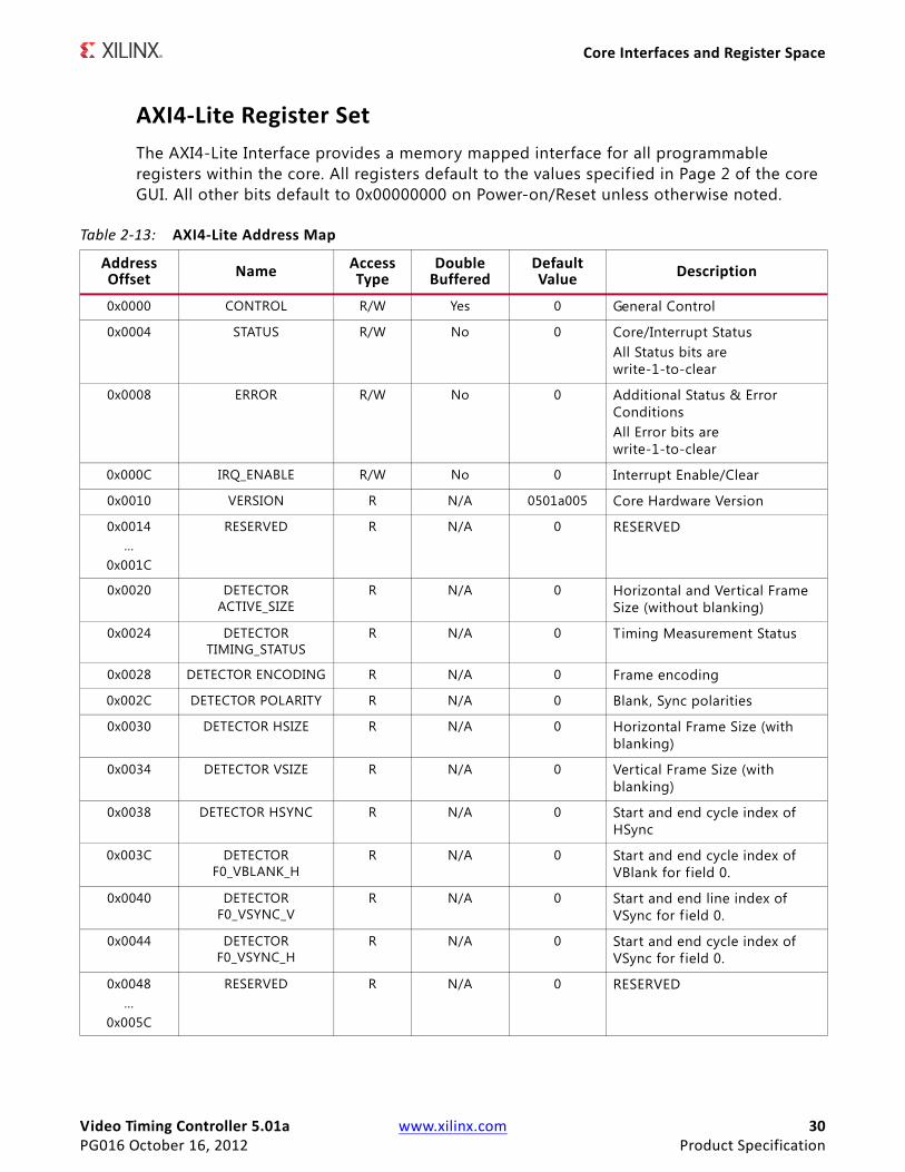
AXI4-Lite Register SetThe AXI4-Lite Interface provides a memory mapped interface for all programmable registers within the core. All registers default to the values specif ied in Page 2 of the core GUI. All other bits default to 0x00000000 on Power-on/Reset unless otherwise noted.
Table 2-13: AXI4-Lite Address Map
Address Offset Name Access
TypeDouble
BufferedDefault Value Description
0x0000 CONTROL R/W Yes 0 General Control
0x0004 STATUS R/W No 0 Core/Interrupt StatusAll Status bits are write-1-to-clear
0x0008 ERROR R/W No 0 Additional Status & Error ConditionsAll Error bits are write-1-to-clear
0x000C IRQ_ENABLE R/W No 0 Interrupt Enable/Clear
0x0010 VERSION R N/A 0501a005 Core Hardware Version
0x0014…
0x001C
RESERVED R N/A 0 RESERVED
0x0020 DETECTOR ACTIVE_SIZE
R N/A 0 Horizontal and Vertical Frame Size (without blanking)
0x0024 DETECTOR TIMING_STATUS
R N/A 0 Timing Measurement Status
0x0028 DETECTOR ENCODING R N/A 0 Frame encoding
0x002C DETECTOR POLARITY R N/A 0 Blank, Sync polarities
0x0030 DETECTOR HSIZE R N/A 0 Horizontal Frame Size (with blanking)
0x0034 DETECTOR VSIZE R N/A 0 Vertical Frame Size (with blanking)
0x0038 DETECTOR HSYNC R N/A 0 Start and end cycle index of HSync
0x003C DETECTOR F0_VBLANK_H
R N/A 0 Start and end cycle index of VBlank for f ield 0.
0x0040 DETECTOR F0_VSYNC_V
R N/A 0 Start and end line index of VSync for f ield 0.
0x0044 DETECTOR F0_VSYNC_H
R N/A 0 Start and end cycle index of VSync for f ield 0.
0x0048…
0x005C
RESERVED R N/A 0 RESERVED
Video Timing Controller 5.01a www.xilinx.com 31PG016 October 16, 2012 Product Specification
Core Interfaces and Register Space
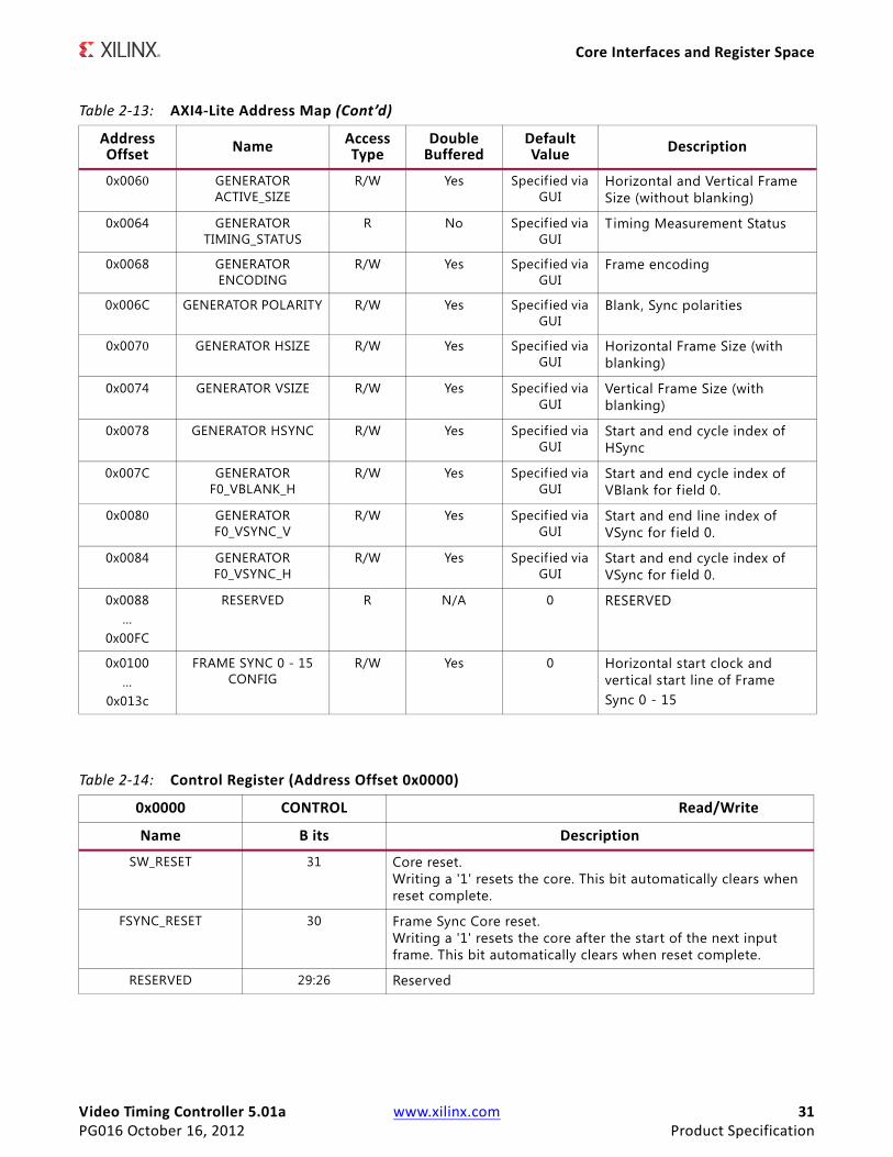
0x0060 GENERATOR ACTIVE_SIZE
R/W Yes Specif ied via GUI
Horizontal and Vertical Frame Size (without blanking)
0x0064 GENERATOR TIMING_STATUS
R No Specif ied via GUI
Timing Measurement Status
0x0068 GENERATOR ENCODING
R/W Yes Specif ied via GUI
Frame encoding
0x006C GENERATOR POLARITY R/W Yes Specif ied via GUI
Blank, Sync polarities
0x0070 GENERATOR HSIZE R/W Yes Specif ied via GUI
Horizontal Frame Size (with blanking)
0x0074 GENERATOR VSIZE R/W Yes Specif ied via GUI
Vertical Frame Size (with blanking)
0x0078 GENERATOR HSYNC R/W Yes Specif ied via GUI
Start and end cycle index of HSync
0x007C GENERATOR F0_VBLANK_H
R/W Yes Specif ied via GUI
Start and end cycle index of VBlank for f ield 0.
0x0080 GENERATOR F0_VSYNC_V
R/W Yes Specif ied via GUI
Start and end line index of VSync for f ield 0.
0x0084 GENERATOR F0_VSYNC_H
R/W Yes Specif ied via GUI
Start and end cycle index of VSync for f ield 0.
0x0088…
0x00FC
RESERVED R N/A 0 RESERVED
0x0100…
0x013c
FRAME SYNC 0 - 15 CONFIG
R/W Yes 0 Horizontal start clock and vertical start line of FrameSync 0 - 15
Table 2-13: AXI4-Lite Address Map (Cont’d)
Address Offset Name Access
TypeDouble
BufferedDefault Value Description
Table 2-14: Control Register (Address Offset 0x0000)
0x0000 CONTROL Read/Write
Name B its Description
SW_RESET 31 Core reset. Writing a '1' resets the core. This bit automatically clears when reset complete.
FSYNC_RESET 30 Frame Sync Core reset. Writing a '1' resets the core after the start of the next input frame. This bit automatically clears when reset complete.
RESERVED 29:26 Reserved
Video Timing Controller 5.01a www.xilinx.com 32PG016 October 16, 2012 Product Specification
Core Interfaces and Register Space
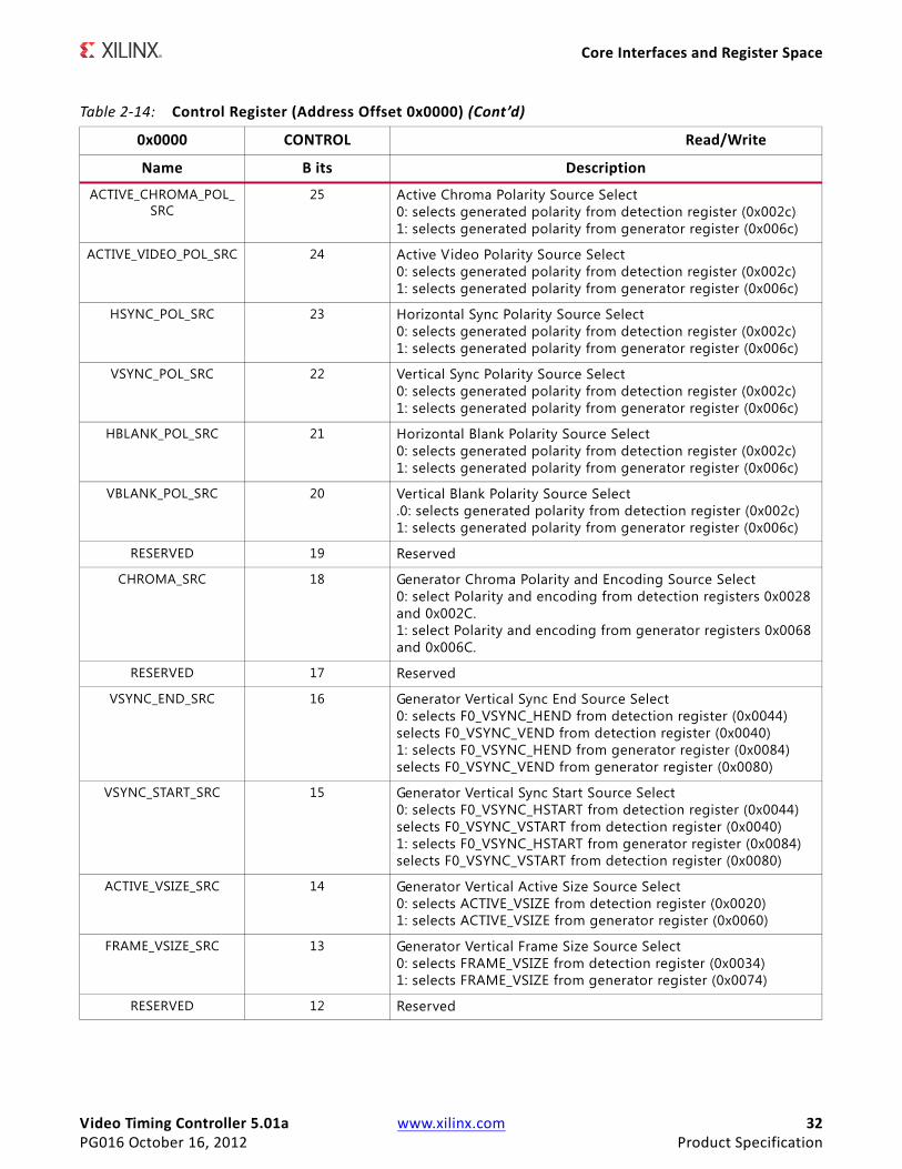
ACTIVE_CHROMA_POL_SRC
25 Active Chroma Polarity Source Select 0: selects generated polarity from detection register (0x002c) 1: selects generated polarity from generator register (0x006c)
ACTIVE_VIDEO_POL_SRC 24 Active Video Polarity Source Select 0: selects generated polarity from detection register (0x002c) 1: selects generated polarity from generator register (0x006c)
HSYNC_POL_SRC 23 Horizontal Sync Polarity Source Select 0: selects generated polarity from detection register (0x002c)1: selects generated polarity from generator register (0x006c)
VSYNC_POL_SRC 22 Vertical Sync Polarity Source Select0: selects generated polarity from detection register (0x002c)1: selects generated polarity from generator register (0x006c)
HBLANK_POL_SRC 21 Horizontal Blank Polarity Source Select0: selects generated polarity from detection register (0x002c)1: selects generated polarity from generator register (0x006c)
VBLANK_POL_SRC 20 Vertical Blank Polarity Source Select.0: selects generated polarity from detection register (0x002c)1: selects generated polarity from generator register (0x006c)
RESERVED 19 Reserved
CHROMA_SRC 18 Generator Chroma Polarity and Encoding Source Select0: select Polarity and encoding from detection registers 0x0028 and 0x002C.1: select Polarity and encoding from generator registers 0x0068 and 0x006C.
RESERVED 17 Reserved
VSYNC_END_SRC 16 Generator Vertical Sync End Source Select0: selects F0_VSYNC_HEND from detection register (0x0044)selects F0_VSYNC_VEND from detection register (0x0040)1: selects F0_VSYNC_HEND from generator register (0x0084)selects F0_VSYNC_VEND from generator register (0x0080)
VSYNC_START_SRC 15 Generator Vertical Sync Start Source Select0: selects F0_VSYNC_HSTART from detection register (0x0044)selects F0_VSYNC_VSTART from detection register (0x0040)1: selects F0_VSYNC_HSTART from generator register (0x0084)selects F0_VSYNC_VSTART from detection register (0x0080)
ACTIVE_VSIZE_SRC 14 Generator Vertical Active Size Source Select0: selects ACTIVE_VSIZE from detection register (0x0020)1: selects ACTIVE_VSIZE from generator register (0x0060)
FRAME_VSIZE_SRC 13 Generator Vertical Frame Size Source Select0: selects FRAME_VSIZE from detection register (0x0034)1: selects FRAME_VSIZE from generator register (0x0074)
RESERVED 12 Reserved
Table 2-14: Control Register (Address Offset 0x0000) (Cont’d)
0x0000 CONTROL Read/Write
Name B its Description
Video Timing Controller 5.01a www.xilinx.com 33PG016 October 16, 2012 Product Specification
Core Interfaces and Register Space
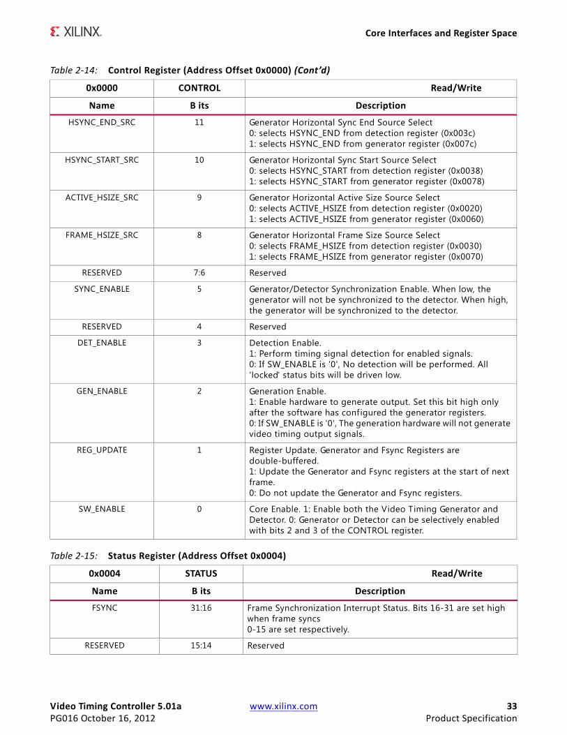
HSYNC_END_SRC 11 Generator Horizontal Sync End Source Select0: selects HSYNC_END from detection register (0x003c)1: selects HSYNC_END from generator register (0x007c)
HSYNC_START_SRC 10 Generator Horizontal Sync Start Source Select0: selects HSYNC_START from detection register (0x0038)1: selects HSYNC_START from generator register (0x0078)
ACTIVE_HSIZE_SRC 9 Generator Horizontal Active Size Source Select0: selects ACTIVE_HSIZE from detection register (0x0020)1: selects ACTIVE_HSIZE from generator register (0x0060)
FRAME_HSIZE_SRC 8 Generator Horizontal Frame Size Source Select0: selects FRAME_HSIZE from detection register (0x0030)1: selects FRAME_HSIZE from generator register (0x0070)
RESERVED 7:6 Reserved
SYNC_ENABLE 5 Generator/Detector Synchronization Enable. When low, the generator will not be synchronized to the detector. When high, the generator will be synchronized to the detector.
RESERVED 4 Reserved
DET_ENABLE 3 Detection Enable. 1: Perform timing signal detection for enabled signals.0: If SW_ENABLE is '0', No detection will be performed. All 'locked' status bits will be driven low.
GEN_ENABLE 2 Generation Enable.1: Enable hardware to generate output. Set this bit high only after the software has configured the generator registers.0: If SW_ENABLE is '0', The generation hardware will not generate video timing output signals.
REG_UPDATE 1 Register Update. Generator and Fsync Registers are double-buffered. 1: Update the Generator and Fsync registers at the start of next frame. 0: Do not update the Generator and Fsync registers.
SW_ENABLE 0 Core Enable. 1: Enable both the Video Timing Generator and Detector. 0: Generator or Detector can be selectively enabled with bits 2 and 3 of the CONTROL register.
Table 2-14: Control Register (Address Offset 0x0000) (Cont’d)
0x0000 CONTROL Read/Write
Name B its Description
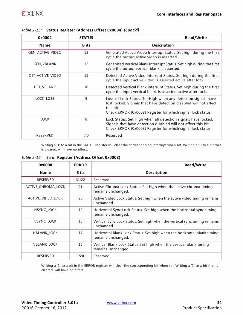
Table 2-15: Status Register (Address Offset 0x0004)
0x0004 STATUS Read/Write
Name B its Description
FSYNC 31:16 Frame Synchronization Interrupt Status. Bits 16-31 are set high when frame syncs 0-15 are set respectively.
RESERVED 15:14 Reserved
Video Timing Controller 5.01a www.xilinx.com 34PG016 October 16, 2012 Product Specification
Core Interfaces and Register Space
Writing a '1' to a bit in the STATUS register will clear the corresponding interrupt when set. Writing a '1' to a bit that is cleared, will have no effect.
Writing a '1' to a bit in the ERROR register will clear the corresponding bit when set. Writing a '1' to a bit that is cleared, will have no effect.
GEN_ACTIVE_VIDEO 13 Generated Active Video Interrupt Status. Set high during the f irst cycle the output active video is asserted.
GEN_VBLANK 12 Generated Vertical Blank Interrupt Status. Set high during the first cycle the output vertical blank is asserted.
DET_ACTIVE_VIDEO 11 Detected Active Video Interrupt Status. Set high during the first cycle the input active video is asserted active after lock.
DET_VBLANK 10 Detected Vertical Blank Interrupt Status. Set high during the f irst cycle the input vertical blank is asserted active after lock.
LOCK_LOSS 9 Loss-of-Lock Status. Set High when any detection signals have lost locked. Signals that have detection disabled will not affect this bit. Check ERROR (0x0008) Register for which signal lock status.
LOCK 8 Lock Status. Set High when all detection signals have locked. Signals that have detection disabled will not affect this bit. Check ERROR (0x0008) Register for which signal lock status.
RESERVED 7:0 Reserved
Table 2-15: Status Register (Address Offset 0x0004) (Cont’d)
0x0004 STATUS Read/Write
Name B its Description
Table 2-16: Error Register (Address Offset 0x0008)
0x0008 ERROR Read/Write
Name B its Description
RESERVED 31:22 Reserved
ACTIVE_CHROMA_LOCK 21 Active Chroma Lock Status. Set high when the active chroma timing remains unchanged.
ACTIVE_VIDEO_LOCK 20 Active Video Lock Status. Set high when the active video timing remains unchanged.
HSYNC_LOCK 19 Horizontal Sync Lock Status. Set high when the horizontal sync timing remains unchanged.
VSYNC_LOCK 18 Vertical Sync Lock Status. Set high when the vertical sync timing remains unchanged.
HBLANK_LOCK 17 Horizontal Blank Lock Status. Set high when the horizontal blank timing remains unchanged.
VBLANK_LOCK 16 Vertical Blank Lock Status Set high when the vertical blank timing remains Unchanged.
RESERVED 15:0 Reserved
Video Timing Controller 5.01a www.xilinx.com 35PG016 October 16, 2012 Product Specification
Core Interfaces and Register Space
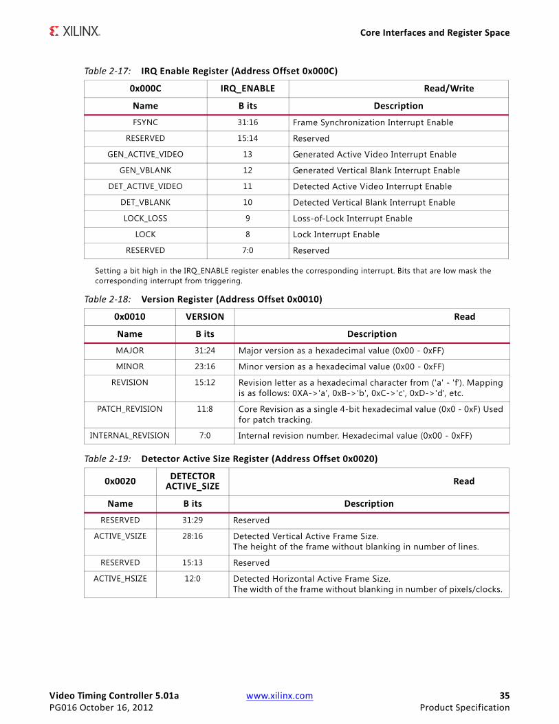
Setting a bit high in the IRQ_ENABLE register enables the corresponding interrupt. Bits that are low mask the corresponding interrupt from triggering.
Table 2-17: IRQ Enable Register (Address Offset 0x000C)
0x000C IRQ_ENABLE Read/Write
Name B its Description
FSYNC 31:16 Frame Synchronization Interrupt Enable
RESERVED 15:14 Reserved
GEN_ACTIVE_VIDEO 13 Generated Active Video Interrupt Enable
GEN_VBLANK 12 Generated Vertical Blank Interrupt Enable
DET_ACTIVE_VIDEO 11 Detected Active Video Interrupt Enable
DET_VBLANK 10 Detected Vertical Blank Interrupt Enable
LOCK_LOSS 9 Loss-of-Lock Interrupt Enable
LOCK 8 Lock Interrupt Enable
RESERVED 7:0 Reserved
Table 2-18: Version Register (Address Offset 0x0010)
0x0010 VERSION Read
Name B its Description
MAJOR 31:24 Major version as a hexadecimal value (0x00 - 0xFF)
MINOR 23:16 Minor version as a hexadecimal value (0x00 - 0xFF)
REVISION 15:12 Revision letter as a hexadecimal character from ('a' - 'f'). Mapping is as follows: 0XA->'a', 0xB->'b', 0xC->'c', 0xD->'d', etc.
PATCH_REVISION 11:8 Core Revision as a single 4-bit hexadecimal value (0x0 - 0xF) Used for patch tracking.
INTERNAL_REVISION 7:0 Internal revision number. Hexadecimal value (0x00 - 0xFF)
Table 2-19: Detector Active Size Register (Address Offset 0x0020)
0x0020 DETECTOR ACTIVE_SIZE Read
Name B its Description
RESERVED 31:29 Reserved
ACTIVE_VSIZE 28:16 Detected Vertical Active Frame Size.The height of the frame without blanking in number of lines.
RESERVED 15:13 Reserved
ACTIVE_HSIZE 12:0 Detected Horizontal Active Frame Size. The width of the frame without blanking in number of pixels/clocks.
Video Timing Controller 5.01a www.xilinx.com 36PG016 October 16, 2012 Product Specification
Core Interfaces and Register Space
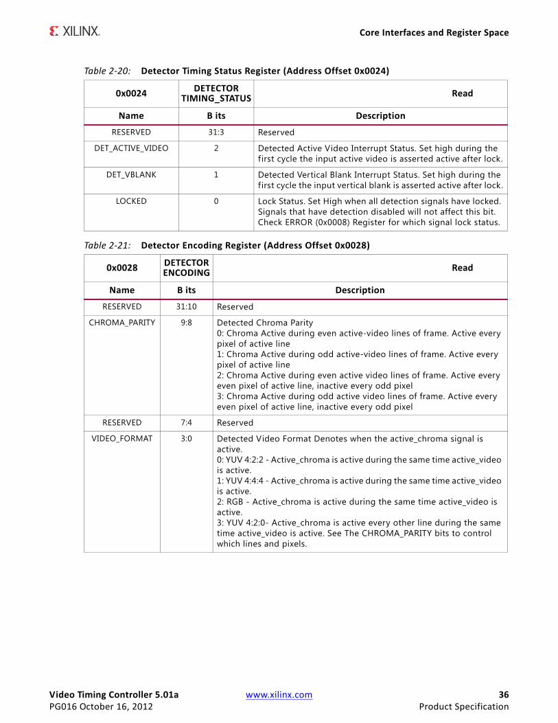
Table 2-20: Detector Timing Status Register (Address Offset 0x0024)
0x0024 DETECTOR TIMING_STATUS Read
Name B its Description
RESERVED 31:3 Reserved
DET_ACTIVE_VIDEO 2 Detected Active Video Interrupt Status. Set high during the first cycle the input active video is asserted active after lock.
DET_VBLANK 1 Detected Vertical Blank Interrupt Status. Set high during the first cycle the input vertical blank is asserted active after lock.
LOCKED 0 Lock Status. Set High when all detection signals have locked. Signals that have detection disabled will not affect this bit. Check ERROR (0x0008) Register for which signal lock status.
Table 2-21: Detector Encoding Register (Address Offset 0x0028)
0x0028 DETECTOR ENCODING Read
Name B its Description
RESERVED 31:10 Reserved
CHROMA_PARITY 9:8 Detected Chroma Parity0: Chroma Active during even active-video lines of frame. Active every pixel of active line1: Chroma Active during odd active-video lines of frame. Active every pixel of active line2: Chroma Active during even active video lines of frame. Active every even pixel of active line, inactive every odd pixel3: Chroma Active during odd active video lines of frame. Active every even pixel of active line, inactive every odd pixel
RESERVED 7:4 Reserved
VIDEO_FORMAT 3:0 Detected Video Format Denotes when the active_chroma signal is active.0: YUV 4:2:2 - Active_chroma is active during the same time active_video is active. 1: YUV 4:4:4 - Active_chroma is active during the same time active_video is active.2: RGB - Active_chroma is active during the same time active_video is active. 3: YUV 4:2:0- Active_chroma is active every other line during the same time active_video is active. See The CHROMA_PARITY bits to control which lines and pixels.
Video Timing Controller 5.01a www.xilinx.com 37PG016 October 16, 2012 Product Specification
Core Interfaces and Register Space
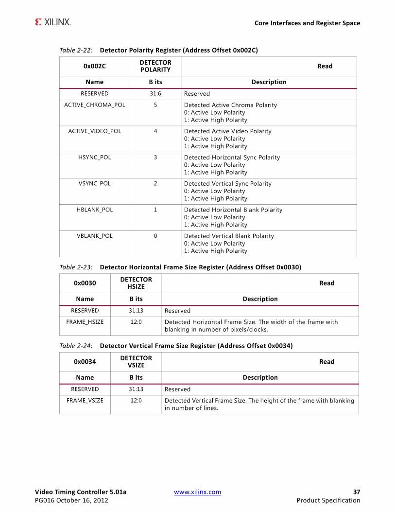
Table 2-22: Detector Polarity Register (Address Offset 0x002C)
0x002C DETECTOR POLARITY Read
Name B its Description
RESERVED 31:6 Reserved
ACTIVE_CHROMA_POL 5 Detected Active Chroma Polarity0: Active Low Polarity 1: Active High Polarity
ACTIVE_VIDEO_POL 4 Detected Active Video Polarity0: Active Low Polarity 1: Active High Polarity
HSYNC_POL 3 Detected Horizontal Sync Polarity0: Active Low Polarity 1: Active High Polarity
VSYNC_POL 2 Detected Vertical Sync Polarity0: Active Low Polarity 1: Active High Polarity
HBLANK_POL 1 Detected Horizontal Blank Polarity0: Active Low Polarity1: Active High Polarity
VBLANK_POL 0 Detected Vertical Blank Polarity0: Active Low Polarity 1: Active High Polarity
Table 2-23: Detector Horizontal Frame Size Register (Address Offset 0x0030)
0x0030 DETECTOR HSIZE Read
Name B its Description
RESERVED 31:13 Reserved
FRAME_HSIZE 12:0 Detected Horizontal Frame Size. The width of the frame with blanking in number of pixels/clocks.
Table 2-24: Detector Vertical Frame Size Register (Address Offset 0x0034)
0x0034 DETECTOR VSIZE Read
Name B its Description
RESERVED 31:13 Reserved
FRAME_VSIZE 12:0 Detected Vertical Frame Size. The height of the frame with blanking in number of lines.
Video Timing Controller 5.01a www.xilinx.com 38PG016 October 16, 2012 Product Specification
Core Interfaces and Register Space
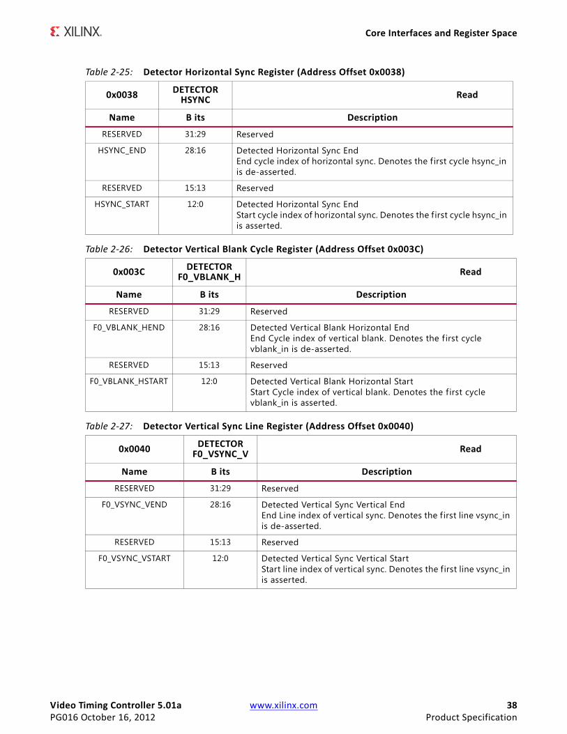
Table 2-25: Detector Horizontal Sync Register (Address Offset 0x0038)
0x0038 DETECTOR HSYNC Read
Name B its Description
RESERVED 31:29 Reserved
HSYNC_END 28:16 Detected Horizontal Sync End End cycle index of horizontal sync. Denotes the f irst cycle hsync_in is de-asserted.
RESERVED 15:13 Reserved
HSYNC_START 12:0 Detected Horizontal Sync End Start cycle index of horizontal sync. Denotes the f irst cycle hsync_in is asserted.
Table 2-26: Detector Vertical Blank Cycle Register (Address Offset 0x003C)
0x003C DETECTOR F0_VBLANK_H Read
Name B its Description
RESERVED 31:29 Reserved
F0_VBLANK_HEND 28:16 Detected Vertical Blank Horizontal EndEnd Cycle index of vertical blank. Denotes the f irst cycle vblank_in is de-asserted.
RESERVED 15:13 Reserved
F0_VBLANK_HSTART 12:0 Detected Vertical Blank Horizontal Start Start Cycle index of vertical blank. Denotes the f irst cycle vblank_in is asserted.
Table 2-27: Detector Vertical Sync Line Register (Address Offset 0x0040)
0x0040 DETECTOR F0_VSYNC_V Read
Name B its Description
RESERVED 31:29 Reserved
F0_VSYNC_VEND 28:16 Detected Vertical Sync Vertical End End Line index of vertical sync. Denotes the f irst line vsync_in is de-asserted.
RESERVED 15:13 Reserved
F0_VSYNC_VSTART 12:0 Detected Vertical Sync Vertical Start Start line index of vertical sync. Denotes the first line vsync_in is asserted.
Video Timing Controller 5.01a www.xilinx.com 39PG016 October 16, 2012 Product Specification
Core Interfaces and Register Space
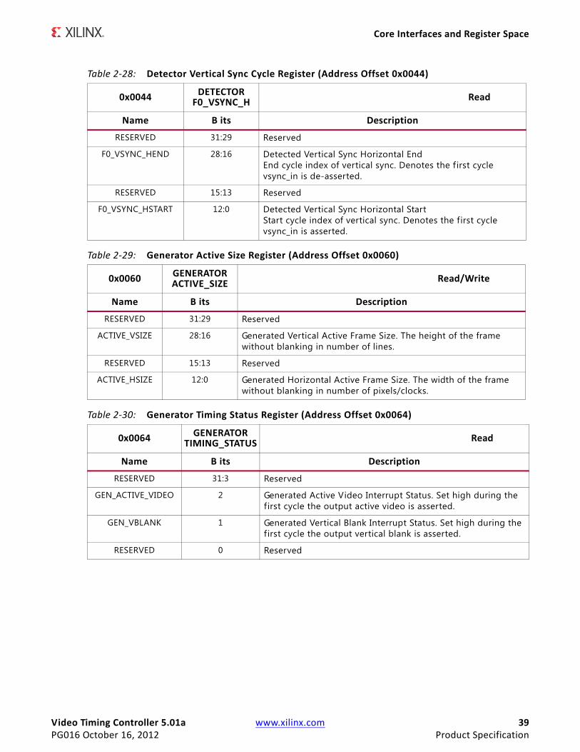
Table 2-28: Detector Vertical Sync Cycle Register (Address Offset 0x0044)
0x0044 DETECTOR F0_VSYNC_H Read
Name B its Description
RESERVED 31:29 Reserved
F0_VSYNC_HEND 28:16 Detected Vertical Sync Horizontal End End cycle index of vertical sync. Denotes the f irst cycle vsync_in is de-asserted.
RESERVED 15:13 Reserved
F0_VSYNC_HSTART 12:0 Detected Vertical Sync Horizontal Start Start cycle index of vertical sync. Denotes the first cycle vsync_in is asserted.
Table 2-29: Generator Active Size Register (Address Offset 0x0060)
0x0060 GENERATOR ACTIVE_SIZE Read/Write
Name B its Description
RESERVED 31:29 Reserved
ACTIVE_VSIZE 28:16 Generated Vertical Active Frame Size. The height of the frame without blanking in number of lines.
RESERVED 15:13 Reserved
ACTIVE_HSIZE 12:0 Generated Horizontal Active Frame Size. The width of the frame without blanking in number of pixels/clocks.
Table 2-30: Generator Timing Status Register (Address Offset 0x0064)
0x0064 GENERATOR TIMING_STATUS Read
Name B its Description
RESERVED 31:3 Reserved
GEN_ACTIVE_VIDEO 2 Generated Active Video Interrupt Status. Set high during the first cycle the output active video is asserted.
GEN_VBLANK 1 Generated Vertical Blank Interrupt Status. Set high during the first cycle the output vertical blank is asserted.
RESERVED 0 Reserved
Video Timing Controller 5.01a www.xilinx.com 40PG016 October 16, 2012 Product Specification
Core Interfaces and Register Space
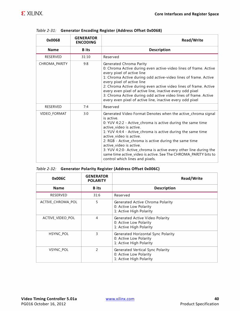
Table 2-31: Generator Encoding Register (Address Offset 0x0068)
0x0068 GENERATOR ENCODING Read/Write
Name B its Description
RESERVED 31:10 Reserved
CHROMA_PARITY 9:8 Generated Chroma Parity 0: Chroma Active during even active-video lines of frame. Active every pixel of active line 1: Chroma Active during odd active-video lines of frame. Active every pixel of active line 2: Chroma Active during even active video lines of frame. Active every even pixel of active line, inactive every odd pixel 3: Chroma Active during odd active video lines of frame. Active every even pixel of active line, inactive every odd pixel
RESERVED 7:4 Reserved
VIDEO_FORMAT 3:0 Generated Video Format Denotes when the active_chroma signal is active. 0: YUV 4:2:2 - Active_chroma is active during the same time active_video is active. 1: YUV 4:4:4 - Active_chroma is active during the same time active_video is active.2: RGB - Active_chroma is active during the same time active_video is active.3: YUV 4:2:0- Active_chroma is active every other line during the same time active_video is active. See The CHROMA_PARITY bits to control which lines and pixels.
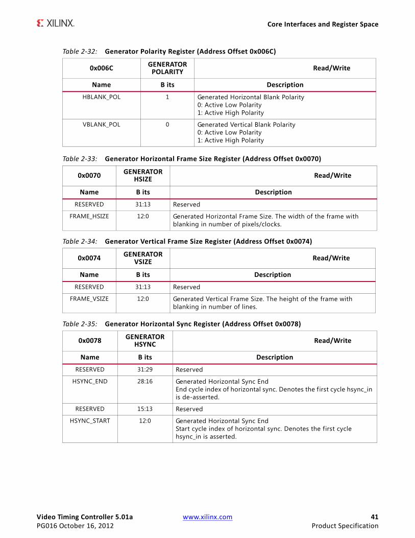
Table 2-32: Generator Polarity Register (Address Offset 0x006C)
0x006C GENERATOR POLARITY Read/Write
Name B its Description
RESERVED 31:6 Reserved
ACTIVE_CHROMA_POL 5 Generated Active Chroma Polarity0: Active Low Polarity 1: Active High Polarity
ACTIVE_VIDEO_POL 4 Generated Active Video Polarity0: Active Low Polarity 1: Active High Polarity
HSYNC_POL 3 Generated Horizontal Sync Polarity0: Active Low Polarity 1: Active High Polarity
VSYNC_POL 2 Generated Vertical Sync Polarity0: Active Low Polarity 1: Active High Polarity
Video Timing Controller 5.01a www.xilinx.com 41PG016 October 16, 2012 Product Specification
Core Interfaces and Register Space
HBLANK_POL 1 Generated Horizontal Blank Polarity0: Active Low Polarity 1: Active High Polarity
VBLANK_POL 0 Generated Vertical Blank Polarity0: Active Low Polarity1: Active High Polarity
Table 2-33: Generator Horizontal Frame Size Register (Address Offset 0x0070)
0x0070 GENERATOR HSIZE Read/Write
Name B its Description
RESERVED 31:13 Reserved
FRAME_HSIZE 12:0 Generated Horizontal Frame Size. The width of the frame with blanking in number of pixels/clocks.
Table 2-34: Generator Vertical Frame Size Register (Address Offset 0x0074)
0x0074 GENERATOR VSIZE Read/Write
Name B its Description
RESERVED 31:13 Reserved
FRAME_VSIZE 12:0 Generated Vertical Frame Size. The height of the frame with blanking in number of lines.
Table 2-35: Generator Horizontal Sync Register (Address Offset 0x0078)
0x0078 GENERATOR HSYNC Read/Write
Name B its Description
RESERVED 31:29 Reserved
HSYNC_END 28:16 Generated Horizontal Sync EndEnd cycle index of horizontal sync. Denotes the f irst cycle hsync_in is de-asserted.
RESERVED 15:13 Reserved
HSYNC_START 12:0 Generated Horizontal Sync End Start cycle index of horizontal sync. Denotes the first cycle hsync_in is asserted.
Table 2-32: Generator Polarity Register (Address Offset 0x006C)
0x006C GENERATOR POLARITY Read/Write
Name B its Description
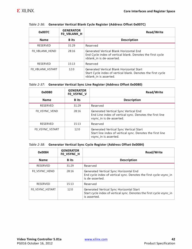
Video Timing Controller 5.01a www.xilinx.com 42PG016 October 16, 2012 Product Specification
Core Interfaces and Register Space
Table 2-36: Generator Vertical Blank Cycle Register (Address Offset 0x007C)
0x007C GENERATOR F0_VBLANK_H Read/Write
Name B its Description
RESERVED 31:29 Reserved
F0_VBLANK_HEND 28:16 Generated Vertical Blank Horizontal EndEnd Cycle index of vertical blank. Denotes the first cycle vblank_in is de-asserted.
RESERVED 15:13 Reserved
F0_VBLANK_HSTART 12:0 Generated Vertical Blank Horizontal Start Start Cycle index of vertical blank. Denotes the first cycle vblank_in is asserted.
Table 2-37: Generator Vertical Sync Line Register (Address Offset 0x0080)
0x0080 GENERATOR F0_VSYNC_V Read/Write
Name B its Description
RESERVED 31:29 Reserved
F0_VSYNC_VEND 28:16 Generated Vertical Sync Vertical End End Line index of vertical sync. Denotes the f irst line vsync_in is de-asserted.
RESERVED 15:13 Reserved
F0_VSYNC_VSTART 12:0 Generated Vertical Sync Vertical StartStart line index of vertical sync. Denotes the f irst line vsync_in is asserted.
Table 2-38: Generator Vertical Sync Cycle Register (Address Offset 0x0084)
0x0084 GENERATOR F0_VSYNC_H Read/Write
Name B its Description
RESERVED 31:29 Reserved
F0_VSYNC_HEND 28:16 Generated Vertical Sync Horizontal End End cycle index of vertical sync. Denotes the first cycle vsync_in is de-asserted.
RESERVED 15:13 Reserved
F0_VSYNC_HSTART 12:0 Generated Vertical Sync Horizontal Start Start cycle index of vertical sync. Denotes the first cycle vsync_in is asserted.
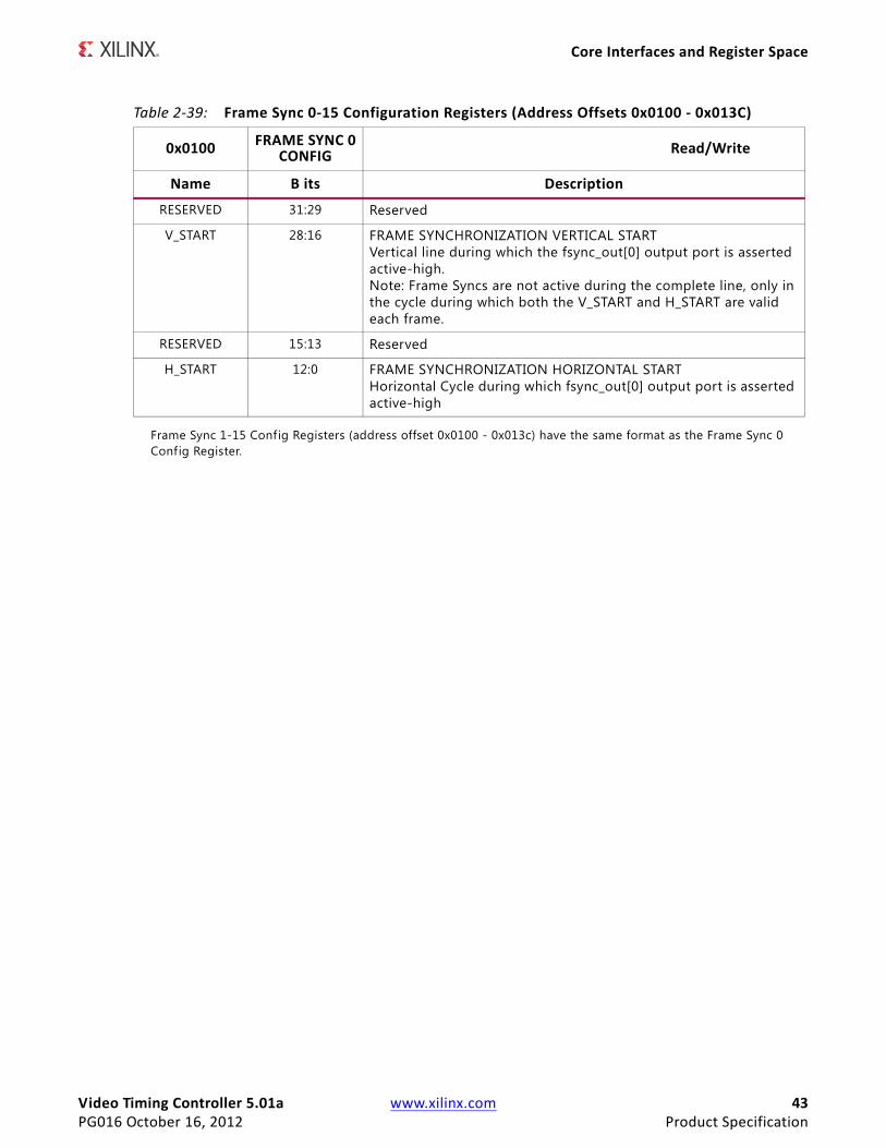
Video Timing Controller 5.01a www.xilinx.com 43PG016 October 16, 2012 Product Specification
Core Interfaces and Register Space
Frame Sync 1-15 Config Registers (address offset 0x0100 - 0x013c) have the same format as the Frame Sync 0 Config Register.
Table 2-39: Frame Sync 0-15 Configuration Registers (Address Offsets 0x0100 - 0x013C)
0x0100 FRAME SYNC 0 CONFIG Read/Write
Name B its Description
RESERVED 31:29 Reserved
V_START 28:16 FRAME SYNCHRONIZATION VERTICAL START Vertical line during which the fsync_out[0] output port is asserted active-high. Note: Frame Syncs are not active during the complete line, only in the cycle during which both the V_START and H_START are valid each frame.
RESERVED 15:13 Reserved
H_START 12:0 FRAME SYNCHRONIZATION HORIZONTAL START Horizontal Cycle during which fsync_out[0] output port is asserted active-high
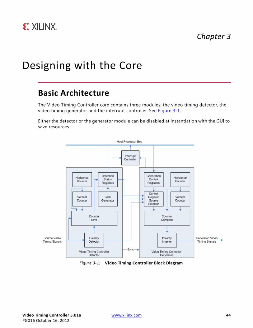
Video Timing Controller 5.01a www.xilinx.com 44PG016 October 16, 2012
Chapter 3
Designing with the Core
Basic ArchitectureThe Video Timing Controller core contains three modules: the video timing detector, the video timing generator and the interrupt controller. See Figure 3-1.
Either the detector or the generator module can be disabled at instantiation with the GUI to save resources.
X-Ref Target - Figure 3-1
Figure 3-1: Video Timing Controller Block Diagram
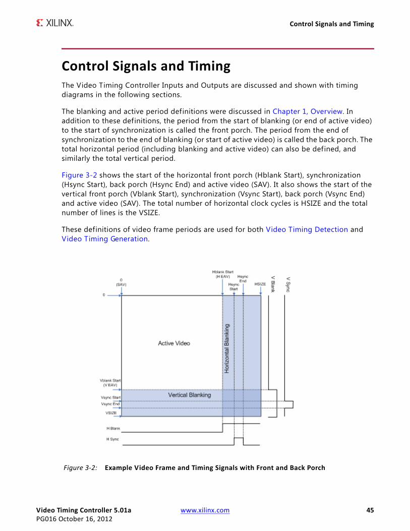
Video Timing Controller 5.01a www.xilinx.com 45PG016 October 16, 2012
Control Signals and Timing
Control Signals and TimingThe Video Timing Controller Inputs and Outputs are discussed and shown with timing diagrams in the following sections.
The blanking and active period definitions were discussed in Chapter 1, Overview. In addition to these definitions, the period from the start of blanking (or end of active video) to the start of synchronization is called the front porch. The period from the end of synchronization to the end of blanking (or start of active video) is called the back porch. The total horizontal period (including blanking and active video) can also be defined, and similarly the total vertical period.
Figure 3-2 shows the start of the horizontal front porch (Hblank Start), synchronization (Hsync Start), back porch (Hsync End) and active video (SAV). It also shows the start of the vertical front porch (Vblank Start), synchronization (Vsync Start), back porch (Vsync End) and active video (SAV). The total number of horizontal clock cycles is HSIZE and the total number of lines is the VSIZE.
These definitions of video frame periods are used for both Video Timing Detection and Video Timing Generation.
X-Ref Target - Figure 3-2
Figure 3-2: Example Video Frame and Timing Signals with Front and Back Porch
Video Timing Controller 5.01a www.xilinx.com 46PG016 October 16, 2012
Control Signals and Timing
Video Timing DetectionThe Video Timing Controller has six optional inputs for detecting the timing of the input video signal: vertical blank, vertical synchronization, horizontal blank, horizontal synchronization, active video and active chroma. The minimum set of inputs required to detect is either vertical blank, horizontal blank and active video or vertical sync, horizontal sync and active video. To enable detection, the Enable Detection GUI parameter must be set, and the control register bit 1 must also be set. The GUI parameter allows saving FPGA resources. The Control Register allows run-time flexibility. Other GUI parameters can be set to selectively disable detection of one or more input video timing signals.
The detected polarity of each input signal is shown by bits 0-5 of the Detection Polarity Register (address offset 0x2C). High denotes active high polarity, and low denotes active low polarity. Bits 8 and 9 of the Detection Encoding Register shows the number of lines skipped between each active chroma line. Bit 8 High denotes that every other line is skipped (4:2:0), and low denotes that no lines are skipped (4:4:4 or 4:2:2). Bit 9 High denotes that every other pixel is skipped, and low denotes that no pixels are skipped.
If any input (vblank_in, vsync_in, hblank_in, hsync_in, active_video_in, active_chroma_in) is not driven or is not connected, then detection for that input must be disabled. To disable detection for an input, deselect the appropriate option in the GUI ("Vertical Blank Detection", "Vertical Sync Detection", etc.).
Video Timing GenerationThe Video Timing Controller can generate up to six output video signals: vertical blank, vertical synchronization, horizontal blank, horizontal synchronization, active video and active chroma. To enable generation of these signals, the Enable Generation GUI parameter must be set, and the control register bit 0 or bit 2 must also be set. Other GUI parameters can be set to selectively disable generation of one or more video timing signals.
The polarity of each output signal can be set by bits 0-5 of the Generator Polarity Register (Address Offset 0x006C). High denotes active high polarity, and low denotes active low polarity. Bits 8 and 9 of the Control Register also sets the number of lines skipped between each active chroma line. Bit 8 High denotes that every other line is skipped (4:2:0), and low denotes that no lines are skipped (4:4:4 or 4:2:2). Bit 9 High denotes that every other pixel is skipped, and low denotes that no pixels are skipped.
The Video Timing Controller has bits in the Control Register called Source Selects to select the internal detection registers or the external input generation registers. These bits allow the detected timing (if enabled) to control the generated outputs or allow the host processor to override each value independently via the generation registers at address offset 0x0060 - 0x0084, as described in Table 2-13.
Table 3-1 through Table 3-6 show example settings of the input control busses and the resultant video timing output signals.
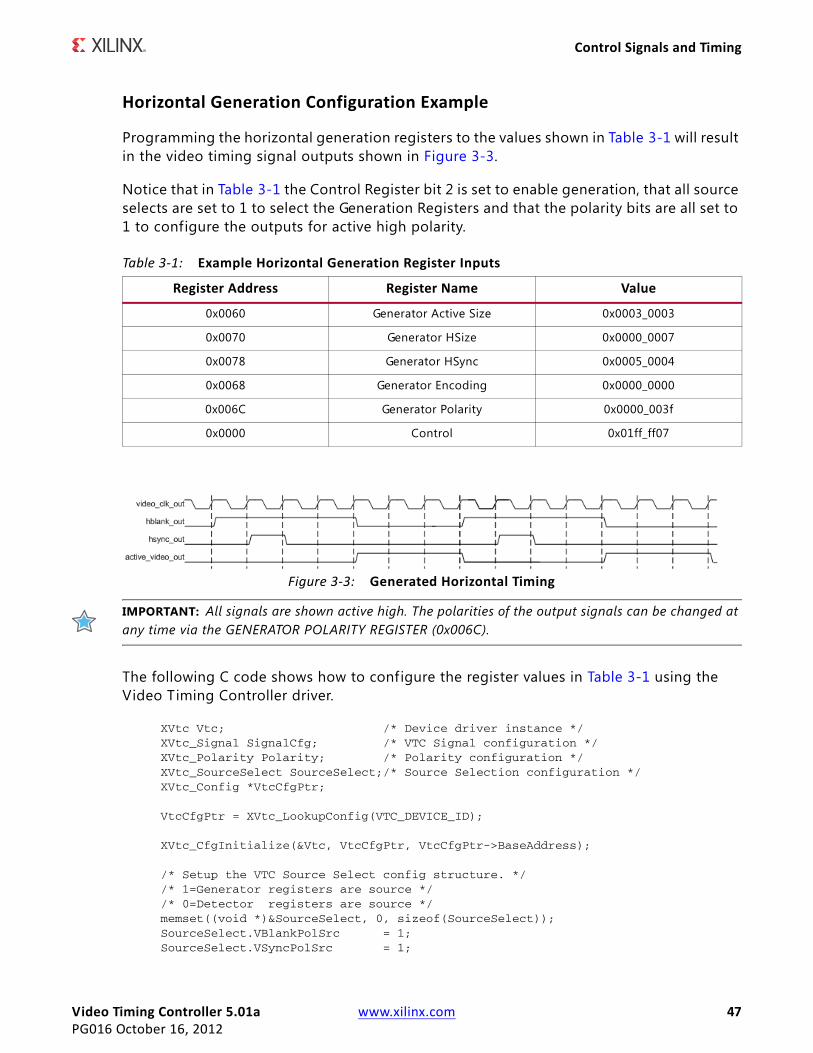
Video Timing Controller 5.01a www.xilinx.com 47PG016 October 16, 2012
Control Signals and Timing
Horizontal Generation Configuration Example
Programming the horizontal generation registers to the values shown in Table 3-1 will result in the video timing signal outputs shown in Figure 3-3.
Notice that in Table 3-1 the Control Register bit 2 is set to enable generation, that all source selects are set to 1 to select the Generation Registers and that the polarity bits are all set to 1 to configure the outputs for active high polarity.
IMPORTANT: All signals are shown active high. The polarities of the output signals can be changed at any time via the GENERATOR POLARITY REGISTER (0x006C).
The following C code shows how to configure the register values in Table 3-1 using the Video Timing Controller driver.
XVtc Vtc; /* Device driver instance */ XVtc_Signal SignalCfg; /* VTC Signal configuration */ XVtc_Polarity Polarity; /* Polarity configuration */ XVtc_SourceSelect SourceSelect;/* Source Selection configuration */ XVtc_Config *VtcCfgPtr;
VtcCfgPtr = XVtc_LookupConfig(VTC_DEVICE_ID);
XVtc_CfgInitialize(&Vtc, VtcCfgPtr, VtcCfgPtr->BaseAddress);
/* Setup the VTC Source Select config structure. */ /* 1=Generator registers are source */ /* 0=Detector registers are source */ memset((void *)&SourceSelect, 0, sizeof(SourceSelect)); SourceSelect.VBlankPolSrc = 1; SourceSelect.VSyncPolSrc = 1;
Table 3-1: Example Horizontal Generation Register Inputs
Register Address Register Name Value
0x0060 Generator Active Size 0x0003_0003
0x0070 Generator HSize 0x0000_0007
0x0078 Generator HSync 0x0005_0004
0x0068 Generator Encoding 0x0000_0000
0x006C Generator Polarity 0x0000_003f
0x0000 Control 0x01ff_ff07
X-Ref Target - Figure 3-3
Figure 3-3: Generated Horizontal Timing
Video Timing Controller 5.01a www.xilinx.com 48PG016 October 16, 2012
Control Signals and Timing
SourceSelect.HBlankPolSrc = 1; SourceSelect.HSyncPolSrc = 1; SourceSelect.ActiveVideoPolSrc = 1; SourceSelect.ActiveChromaPolSrc= 1;
SourceSelect.VChromaSrc = 1; SourceSelect.VActiveSrc = 1; SourceSelect.VBackPorchSrc = 1; SourceSelect.VSyncSrc = 1; SourceSelect.VFrontPorchSrc = 1; SourceSelect.VTotalSrc = 1; SourceSelect.HActiveSrc = 1; SourceSelect.HBackPorchSrc = 1; SourceSelect.HSyncSrc = 1; SourceSelect.HFrontPorchSrc = 1; SourceSelect.HTotalSrc = 1; /* Setup the VTC Polarity config structure. */ memset((void *)&Polarity, 0, sizeof(Polarity)); Polarity.ActiveChromaPol = 1; Polarity.ActiveVideoPol = 1; Polarity.VBlankPol = 1; Polarity.VSyncPol = 1; Polarity.HBlankPol = 1; Polarity.HSyncPol = 1; /* Setup the VTC Signal config structure. */ memset((void *)&SignalCfg, 0, sizeof(XVtc_Signal)); SignalCfg.OriginMode = 1;//Set Frame Origin to Start of Active Video SignalCfg.HTotal = 7; SignalCfg.HActiveStart = 0; SignalCfg.HFrontPorchStart = 3;// Active Video Width SignalCfg.HSyncStart = 4;// Active Video Width + FP Width SignalCfg.HBackPorchStart = 5;// Active Video Width + FP Width + Sync Width SignalCfg.V0Total = 7; SignalCfg.V0ChromaStart = 0; SignalCfg.V0ActiveStart = 0; SignalCfg.V0FrontPorchStart = 3;// Active Video Height SignalCfg.V0SyncStart = 4;// Active Video Height + FP_Width SignalCfg.V0BackPorchStart = 5;// Active Video Height + FP Width + Sync Width /* Write VTC config to HW */ XVtc_SetPolarity(&Vtc, &Polarity); XVtc_SetGenerator(&Vtc, &SignalCfg); XVtc_SetSource(&Vtc, &SourceSelect);
/* Enable VTC Generator */ XVtc_Enable(&Vtc, XVTC_EN_GENERATOR);
Vertical Generation Configuration Example
Programming the generation registers to the values shown in Table 3-2 will result in the video timing signal outputs shown in Figure 3-4.
Notice that in Table 3-2 the Generator Encoding Register bits [3:0] are set to 0 to configure the number of lines skipped between each active chroma line to be 0. This configures the
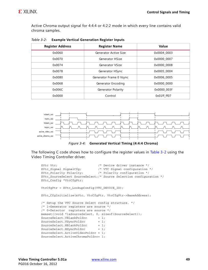
Video Timing Controller 5.01a www.xilinx.com 49PG016 October 16, 2012
Control Signals and Timing
Active Chroma output signal for 4:4:4 or 4:2:2 mode in which every line contains valid chroma samples.
The following C code shows how to configure the register values in Table 3-2 using the Video Timing Controller driver.
XVtc Vtc; /* Device driver instance */ XVtc_Signal SignalCfg; /* VTC Signal configuration */ XVtc_Polarity Polarity; /* Polarity configuration */ XVtc_SourceSelect SourceSelect;/* Source Selection configuration */ XVtc_Config *VtcCfgPtr;
VtcCfgPtr = XVtc_LookupConfig(VTC_DEVICE_ID);
XVtc_CfgInitialize(&Vtc, VtcCfgPtr, VtcCfgPtr->BaseAddress);
/* Setup the VTC Source Select config structure. */ /* 1=Generator registers are source */ /* 0=Detector registers are source */ memset((void *)&SourceSelect, 0, sizeof(SourceSelect)); SourceSelect.VBlankPolSrc = 1; SourceSelect.VSyncPolSrc = 1; SourceSelect.HBlankPolSrc = 1; SourceSelect.HSyncPolSrc = 1; SourceSelect.ActiveVideoPolSrc = 1; SourceSelect.ActiveChromaPolSrc= 1;
Table 3-2: Example Vertical Generation Register Inputs
Register Address Register Name Value
0x0060 Generator Active Size 0x0004_0003
0x0070 Generator HSize 0x0000_0007
0x0074 Generator VSize 0x0000_0008
0x0078 Generator HSync 0x0005_0004
0x0080 Generator Frame 0 Vsync 0x0006_0005
0x0068 Generator Encoding 0x0000_0000
0x006C Generator Polarity 0x0000_003f
0x0000 Control 0x01ff_ff07
X-Ref Target - Figure 3-4
Figure 3-4: Generated Vertical Timing (4:4:4 Chroma)
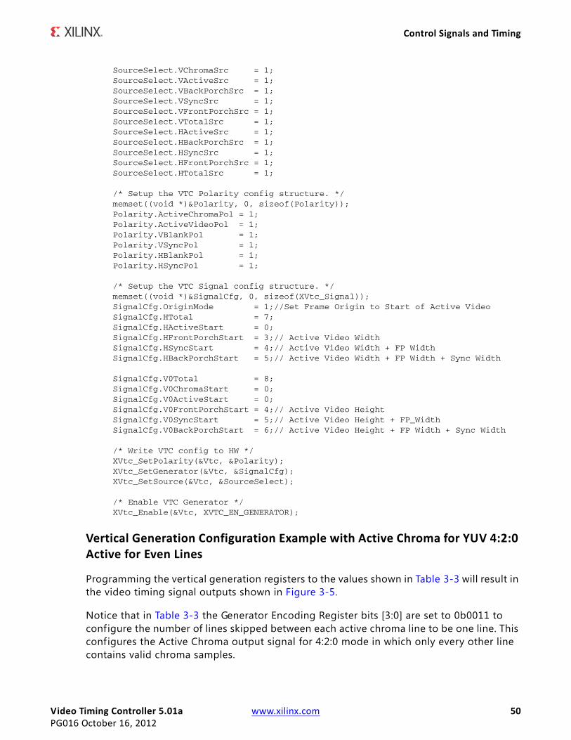
Video Timing Controller 5.01a www.xilinx.com 50PG016 October 16, 2012
Control Signals and Timing
SourceSelect.VChromaSrc = 1; SourceSelect.VActiveSrc = 1; SourceSelect.VBackPorchSrc = 1; SourceSelect.VSyncSrc = 1; SourceSelect.VFrontPorchSrc = 1; SourceSelect.VTotalSrc = 1; SourceSelect.HActiveSrc = 1; SourceSelect.HBackPorchSrc = 1; SourceSelect.HSyncSrc = 1; SourceSelect.HFrontPorchSrc = 1; SourceSelect.HTotalSrc = 1; /* Setup the VTC Polarity config structure. */ memset((void *)&Polarity, 0, sizeof(Polarity)); Polarity.ActiveChromaPol = 1; Polarity.ActiveVideoPol = 1; Polarity.VBlankPol = 1; Polarity.VSyncPol = 1; Polarity.HBlankPol = 1; Polarity.HSyncPol = 1; /* Setup the VTC Signal config structure. */ memset((void *)&SignalCfg, 0, sizeof(XVtc_Signal)); SignalCfg.OriginMode = 1;//Set Frame Origin to Start of Active Video SignalCfg.HTotal = 7; SignalCfg.HActiveStart = 0; SignalCfg.HFrontPorchStart = 3;// Active Video Width SignalCfg.HSyncStart = 4;// Active Video Width + FP Width SignalCfg.HBackPorchStart = 5;// Active Video Width + FP Width + Sync Width SignalCfg.V0Total = 8; SignalCfg.V0ChromaStart = 0; SignalCfg.V0ActiveStart = 0; SignalCfg.V0FrontPorchStart = 4;// Active Video Height SignalCfg.V0SyncStart = 5;// Active Video Height + FP_Width SignalCfg.V0BackPorchStart = 6;// Active Video Height + FP Width + Sync Width /* Write VTC config to HW */ XVtc_SetPolarity(&Vtc, &Polarity); XVtc_SetGenerator(&Vtc, &SignalCfg); XVtc_SetSource(&Vtc, &SourceSelect);
/* Enable VTC Generator */ XVtc_Enable(&Vtc, XVTC_EN_GENERATOR);
Vertical Generation Configuration Example with Active Chroma for YUV 4:2:0 Active for Even Lines
Programming the vertical generation registers to the values shown in Table 3-3 will result in the video timing signal outputs shown in Figure 3-5.
Notice that in Table 3-3 the Generator Encoding Register bits [3:0] are set to 0b0011 to configure the number of lines skipped between each active chroma line to be one line. This configures the Active Chroma output signal for 4:2:0 mode in which only every other line contains valid chroma samples.
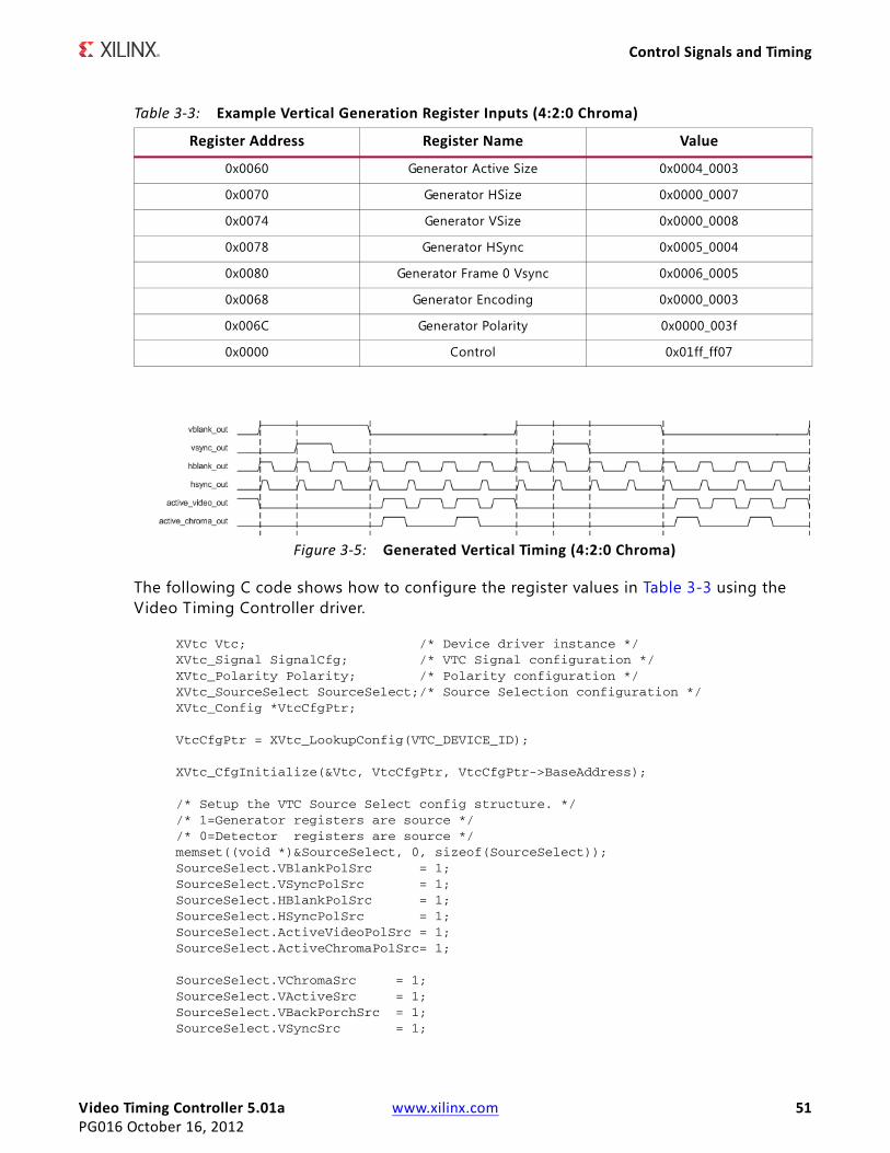
Video Timing Controller 5.01a www.xilinx.com 51PG016 October 16, 2012
Control Signals and Timing
The following C code shows how to configure the register values in Table 3-3 using the Video Timing Controller driver.
XVtc Vtc; /* Device driver instance */ XVtc_Signal SignalCfg; /* VTC Signal configuration */ XVtc_Polarity Polarity; /* Polarity configuration */ XVtc_SourceSelect SourceSelect;/* Source Selection configuration */ XVtc_Config *VtcCfgPtr;
VtcCfgPtr = XVtc_LookupConfig(VTC_DEVICE_ID);
XVtc_CfgInitialize(&Vtc, VtcCfgPtr, VtcCfgPtr->BaseAddress);
/* Setup the VTC Source Select config structure. */ /* 1=Generator registers are source */ /* 0=Detector registers are source */ memset((void *)&SourceSelect, 0, sizeof(SourceSelect)); SourceSelect.VBlankPolSrc = 1; SourceSelect.VSyncPolSrc = 1; SourceSelect.HBlankPolSrc = 1; SourceSelect.HSyncPolSrc = 1; SourceSelect.ActiveVideoPolSrc = 1; SourceSelect.ActiveChromaPolSrc= 1; SourceSelect.VChromaSrc = 1; SourceSelect.VActiveSrc = 1; SourceSelect.VBackPorchSrc = 1; SourceSelect.VSyncSrc = 1;
Table 3-3: Example Vertical Generation Register Inputs (4:2:0 Chroma)
Register Address Register Name Value
0x0060 Generator Active Size 0x0004_0003
0x0070 Generator HSize 0x0000_0007
0x0074 Generator VSize 0x0000_0008
0x0078 Generator HSync 0x0005_0004
0x0080 Generator Frame 0 Vsync 0x0006_0005
0x0068 Generator Encoding 0x0000_0003
0x006C Generator Polarity 0x0000_003f
0x0000 Control 0x01ff_ff07
X-Ref Target - Figure 3-5
Figure 3-5: Generated Vertical Timing (4:2:0 Chroma)
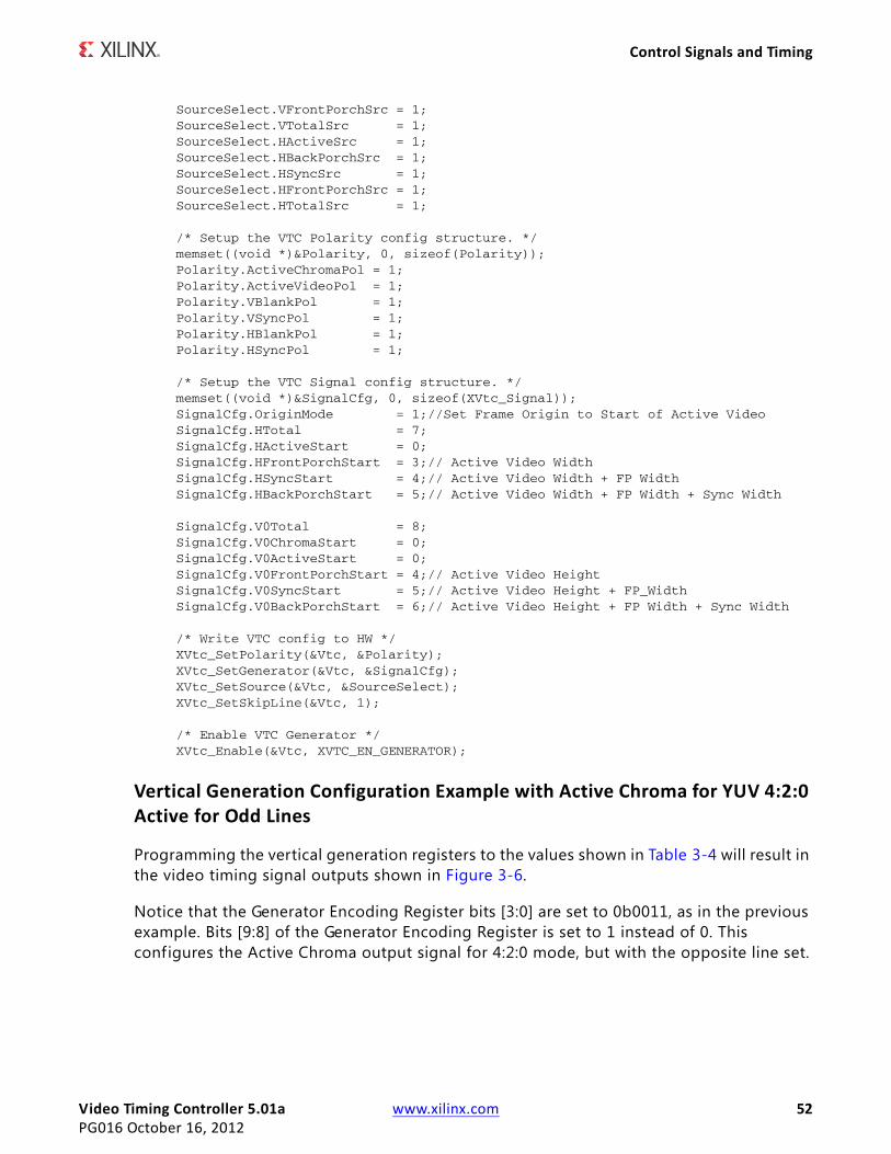
Video Timing Controller 5.01a www.xilinx.com 52PG016 October 16, 2012
Control Signals and Timing
SourceSelect.VFrontPorchSrc = 1; SourceSelect.VTotalSrc = 1; SourceSelect.HActiveSrc = 1; SourceSelect.HBackPorchSrc = 1; SourceSelect.HSyncSrc = 1; SourceSelect.HFrontPorchSrc = 1; SourceSelect.HTotalSrc = 1; /* Setup the VTC Polarity config structure. */ memset((void *)&Polarity, 0, sizeof(Polarity)); Polarity.ActiveChromaPol = 1; Polarity.ActiveVideoPol = 1; Polarity.VBlankPol = 1; Polarity.VSyncPol = 1; Polarity.HBlankPol = 1; Polarity.HSyncPol = 1; /* Setup the VTC Signal config structure. */ memset((void *)&SignalCfg, 0, sizeof(XVtc_Signal)); SignalCfg.OriginMode = 1;//Set Frame Origin to Start of Active Video SignalCfg.HTotal = 7; SignalCfg.HActiveStart = 0; SignalCfg.HFrontPorchStart = 3;// Active Video Width SignalCfg.HSyncStart = 4;// Active Video Width + FP Width SignalCfg.HBackPorchStart = 5;// Active Video Width + FP Width + Sync Width SignalCfg.V0Total = 8; SignalCfg.V0ChromaStart = 0; SignalCfg.V0ActiveStart = 0; SignalCfg.V0FrontPorchStart = 4;// Active Video Height SignalCfg.V0SyncStart = 5;// Active Video Height + FP_Width SignalCfg.V0BackPorchStart = 6;// Active Video Height + FP Width + Sync Width /* Write VTC config to HW */ XVtc_SetPolarity(&Vtc, &Polarity); XVtc_SetGenerator(&Vtc, &SignalCfg); XVtc_SetSource(&Vtc, &SourceSelect); XVtc_SetSkipLine(&Vtc, 1);
/* Enable VTC Generator */ XVtc_Enable(&Vtc, XVTC_EN_GENERATOR);
Vertical Generation Configuration Example with Active Chroma for YUV 4:2:0 Active for Odd Lines
Programming the vertical generation registers to the values shown in Table 3-4 will result in the video timing signal outputs shown in Figure 3-6.
Notice that the Generator Encoding Register bits [3:0] are set to 0b0011, as in the previous example. Bits [9:8] of the Generator Encoding Register is set to 1 instead of 0. This configures the Active Chroma output signal for 4:2:0 mode, but with the opposite line set.
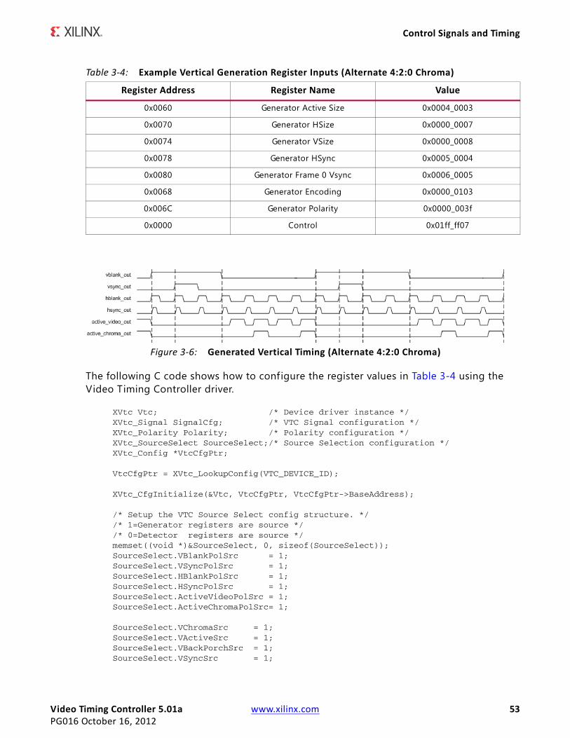
Video Timing Controller 5.01a www.xilinx.com 53PG016 October 16, 2012
Control Signals and Timing
The following C code shows how to configure the register values in Table 3-4 using the Video Timing Controller driver.
XVtc Vtc; /* Device driver instance */ XVtc_Signal SignalCfg; /* VTC Signal configuration */ XVtc_Polarity Polarity; /* Polarity configuration */ XVtc_SourceSelect SourceSelect;/* Source Selection configuration */ XVtc_Config *VtcCfgPtr;
VtcCfgPtr = XVtc_LookupConfig(VTC_DEVICE_ID);
XVtc_CfgInitialize(&Vtc, VtcCfgPtr, VtcCfgPtr->BaseAddress);
/* Setup the VTC Source Select config structure. */ /* 1=Generator registers are source */ /* 0=Detector registers are source */ memset((void *)&SourceSelect, 0, sizeof(SourceSelect)); SourceSelect.VBlankPolSrc = 1; SourceSelect.VSyncPolSrc = 1; SourceSelect.HBlankPolSrc = 1; SourceSelect.HSyncPolSrc = 1; SourceSelect.ActiveVideoPolSrc = 1; SourceSelect.ActiveChromaPolSrc= 1;
SourceSelect.VChromaSrc = 1; SourceSelect.VActiveSrc = 1; SourceSelect.VBackPorchSrc = 1; SourceSelect.VSyncSrc = 1;
Table 3-4: Example Vertical Generation Register Inputs (Alternate 4:2:0 Chroma)
Register Address Register Name Value
0x0060 Generator Active Size 0x0004_0003
0x0070 Generator HSize 0x0000_0007
0x0074 Generator VSize 0x0000_0008
0x0078 Generator HSync 0x0005_0004
0x0080 Generator Frame 0 Vsync 0x0006_0005
0x0068 Generator Encoding 0x0000_0103
0x006C Generator Polarity 0x0000_003f
0x0000 Control 0x01ff_ff07
X-Ref Target - Figure 3-6
Figure 3-6: Generated Vertical Timing (Alternate 4:2:0 Chroma)
Video Timing Controller 5.01a www.xilinx.com 54PG016 October 16, 2012
Control Signals and Timing
SourceSelect.VFrontPorchSrc = 1; SourceSelect.VTotalSrc = 1; SourceSelect.HActiveSrc = 1; SourceSelect.HBackPorchSrc = 1; SourceSelect.HSyncSrc = 1; SourceSelect.HFrontPorchSrc = 1; SourceSelect.HTotalSrc = 1; /* Setup the VTC Polarity config structure. */ memset((void *)&Polarity, 0, sizeof(Polarity)); Polarity.ActiveChromaPol = 1; Polarity.ActiveVideoPol = 1; Polarity.VBlankPol = 1; Polarity.VSyncPol = 1; Polarity.HBlankPol = 1; Polarity.HSyncPol = 1; /* Setup the VTC Signal config structure. */ memset((void *)&SignalCfg, 0, sizeof(XVtc_Signal)); SignalCfg.OriginMode = 1;//Set Frame Origin to Start of Active Video SignalCfg.HTotal = 7; SignalCfg.HActiveStart = 0; SignalCfg.HFrontPorchStart = 3;// Active Video Width SignalCfg.HSyncStart = 4;// Active Video Width + FP Width SignalCfg.HBackPorchStart = 5;// Active Video Width + FP Width + Sync Width SignalCfg.V0Total = 8; SignalCfg.V0ChromaStart = 0; SignalCfg.V0ActiveStart = 1; SignalCfg.V0FrontPorchStart = 4;// Active Video Height SignalCfg.V0SyncStart = 5;// Active Video Height + FP_Width SignalCfg.V0BackPorchStart = 6;// Active Video Height + FP Width + Sync Width /* Write VTC config to HW */ XVtc_SetPolarity(&Vtc, &Polarity); XVtc_SetGenerator(&Vtc, &SignalCfg); XVtc_SetSource(&Vtc, &SourceSelect); XVtc_SetSkipLine(&Vtc, 1);
/* Enable VTC Generator */ XVtc_Enable(&Vtc, XVTC_EN_GENERATOR);
Timing Regeneration Example with Selective Signals Overridden
Table 3-5 shows the detection register values for the source video timing in Figure 3-7. Programming the horizontal generation registers to the values shown in Table 3-6 will result in the video timing signal outputs shown in Figure 3-7.
Table 3-5: Example Horizontal Detection Register Outputs
Register Address Register Name Value
0x0020 Detector Active Size 0x0004_0003
0x0030 Detector HSize 0x0000_0007
0x0038 Detector HSync 0x0005_0004
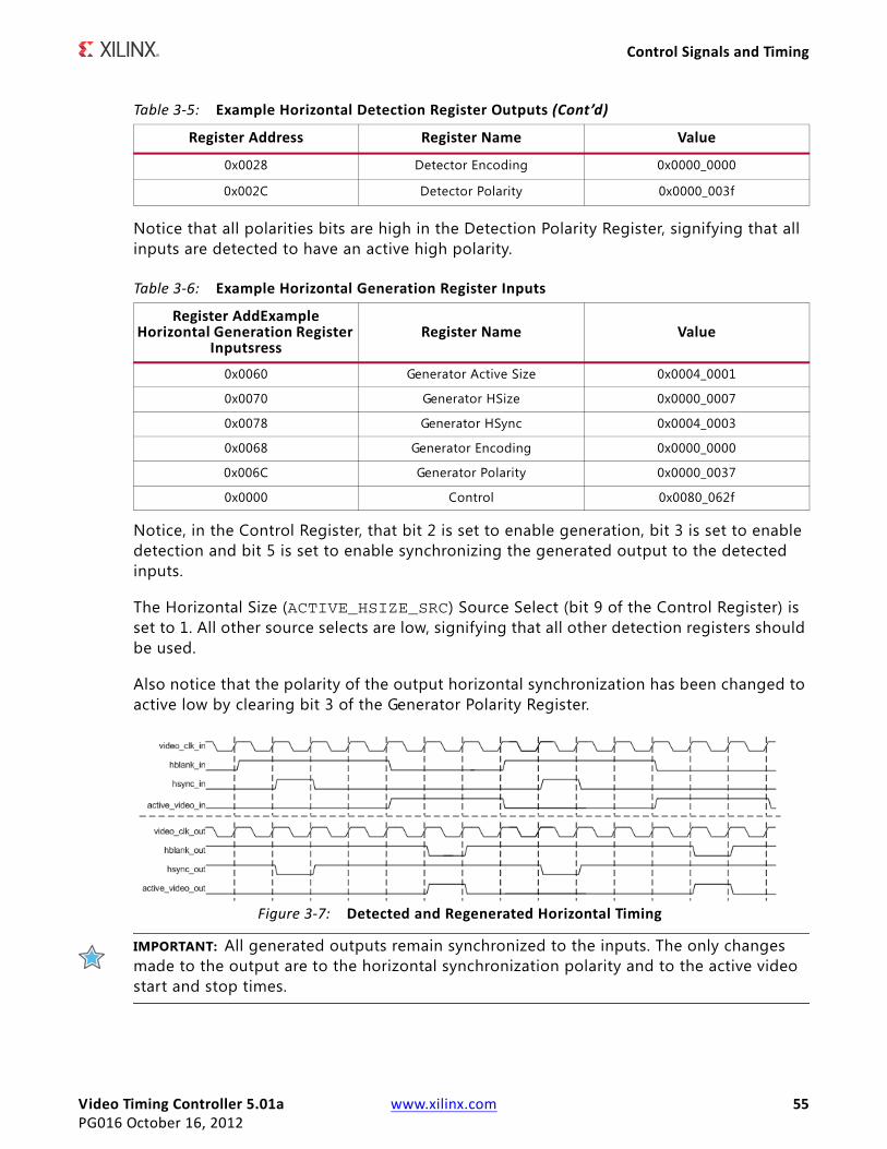
Video Timing Controller 5.01a www.xilinx.com 55PG016 October 16, 2012
Control Signals and Timing
Notice that all polarities bits are high in the Detection Polarity Register, signifying that all inputs are detected to have an active high polarity.
Notice, in the Control Register, that bit 2 is set to enable generation, bit 3 is set to enable detection and bit 5 is set to enable synchronizing the generated output to the detected inputs.
The Horizontal Size (ACTIVE_HSIZE_SRC) Source Select (bit 9 of the Control Register) is set to 1. All other source selects are low, signifying that all other detection registers should be used.
Also notice that the polarity of the output horizontal synchronization has been changed to active low by clearing bit 3 of the Generator Polarity Register.
IMPORTANT: All generated outputs remain synchronized to the inputs. The only changes made to the output are to the horizontal synchronization polarity and to the active video start and stop times.
0x0028 Detector Encoding 0x0000_0000
0x002C Detector Polarity 0x0000_003f
Table 3-6: Example Horizontal Generation Register Inputs
Register AddExample Horizontal Generation Register
InputsressRegister Name Value
0x0060 Generator Active Size 0x0004_0001
0x0070 Generator HSize 0x0000_0007
0x0078 Generator HSync 0x0004_0003
0x0068 Generator Encoding 0x0000_0000
0x006C Generator Polarity 0x0000_0037
0x0000 Control 0x0080_062f
X-Ref Target - Figure 3-7
Figure 3-7: Detected and Regenerated Horizontal Timing
Table 3-5: Example Horizontal Detection Register Outputs (Cont’d)
Register Address Register Name Value
Video Timing Controller 5.01a www.xilinx.com 56PG016 October 16, 2012
Control Signals and Timing
The following C code shows how to configure the register values in Table 3-6 using the Video Timing Controller driver.
XVtc Vtc; /* Device driver instance */ XVtc_Signal SignalCfg; /* VTC Signal configuration */ XVtc_Polarity Polarity; /* Polarity configuration */ XVtc_SourceSelect SourceSelect;/* Source Selection configuration */ XVtc_Config *VtcCfgPtr;
VtcCfgPtr = XVtc_LookupConfig(VTC_DEVICE_ID);
XVtc_CfgInitialize(&Vtc, VtcCfgPtr, VtcCfgPtr->BaseAddress);
/* Setup the VTC Source Select config structure. */ /* 1=Generator registers are source */ /* 0=Detector registers are source */ memset((void *)&SourceSelect, 0, sizeof(SourceSelect)); SourceSelect.VBlankPolSrc = 0; SourceSelect.VSyncPolSrc = 0; SourceSelect.HBlankPolSrc = 0; SourceSelect.HSyncPolSrc = 1; SourceSelect.ActiveVideoPolSrc = 0; SourceSelect.ActiveChromaPolSrc= 0;
SourceSelect.VChromaSrc = 0; SourceSelect.VActiveSrc = 1; SourceSelect.VBackPorchSrc = 0; SourceSelect.VSyncSrc = 0; SourceSelect.VFrontPorchSrc = 0; SourceSelect.VTotalSrc = 0; SourceSelect.HActiveSrc = 0; SourceSelect.HBackPorchSrc = 0; SourceSelect.HSyncSrc = 0; SourceSelect.HFrontPorchSrc = 0; SourceSelect.HTotalSrc = 0; /* Setup the VTC Polarity config structure. */ memset((void *)&Polarity, 0, sizeof(Polarity)); Polarity.ActiveChromaPol = 1; Polarity.ActiveVideoPol = 1; Polarity.VBlankPol = 1; Polarity.VSyncPol = 1; Polarity.HBlankPol = 1; Polarity.HSyncPol = 0; /* Setup the VTC Signal config structure. */ memset((void *)&SignalCfg, 0, sizeof(XVtc_Signal)); SignalCfg.OriginMode = 1;//Set Frame Origin to Start of Active Video SignalCfg.HTotal = 7; SignalCfg.HActiveStart = 0; SignalCfg.HFrontPorchStart = 1;// Active Video Width SignalCfg.HSyncStart = 3;// Active Video Width + FP Width SignalCfg.HBackPorchStart = 4;// Active Video Width + FP Width + Sync Width SignalCfg.V0Total = 8; SignalCfg.V0ChromaStart = 0; SignalCfg.V0ActiveStart = 0; SignalCfg.V0FrontPorchStart = 4;// Active Video Height
Video Timing Controller 5.01a www.xilinx.com 57PG016 October 16, 2012
Control Signals and Timing
SignalCfg.V0SyncStart = 5;// Active Video Height + FP_Width SignalCfg.V0BackPorchStart = 6;// Active Video Height + FP Width + Sync Width /* Write VTC config to HW */ XVtc_SetPolarity(&Vtc, &Polarity); XVtc_SetGenerator(&Vtc, &SignalCfg); XVtc_SetSource(&Vtc, &SourceSelect); XVtc_EnableSync&Vtc);// Synchronize the Generator to the Detector
/* Enable VTC Generator */ XVtc_Enable(&Vtc, XVTC_EN_GENERATOR|XVTC_EN_DETECTOR);
SynchronizationGeneration of the video timing output signals can be synchronized to the detected video timing input signals or generated independently. Synchronization of the output to the input allows the developer to override each individual timing signal with different settings such as signal polarity or start time. For example, the active video signal could be regenerated shifted one cycle earlier or later. This provides a flexible method for regenerating video timing output signals with different settings while remaining synchronized to the input timing.
The Video Timing Controller also has a GUI parameter, called Auto Generation Mode, to control the behavior of the generated outputs based on the detected inputs. When the Auto Generation Mode parameter is set, the generated video timing outputs will change based on the detected inputs. If this parameter is not set, then the video timing outputs will be generated based on only the first detected input format. (If the detector loses lock, the generated outputs will continue to be generated.) To change output timing while Auto Generation Mode is set, timing detection must f irst be disabled by clearing bit 1 in the Control Register and then re-enabling, if any of the Source Select bits are low.
Frame SyncsThe Video Timing Controller has a frame synchronization output bus. Each bit can be configured to toggle high for any one clock cycle during each video frame. Each bit is independently configured for horizontal and vertical clock cycle position with the Frame Sync Configuration Registers (address offsets 0x0100 - 0x013c).
InterruptsThe Video Timing Controller has an active high interrupt output port named "irq". This output is set high when an interrupt occurs and set low when the interrupt event has been cleared. The Video Timing Controller also contains three 32-bit registers for configuring and reporting status of interrupts: the Interrupt Status/Clear, the Interrupt Enable and the Interrupt Clear Registers. A logical AND is performed on the Interrupt Enable Register and the Interrupt Status Register to set the interrupt output high. The Interrupt Clear Register is used to clear the Interrupt Status Register. Writing a '1' to a bit in the Interrupt Status
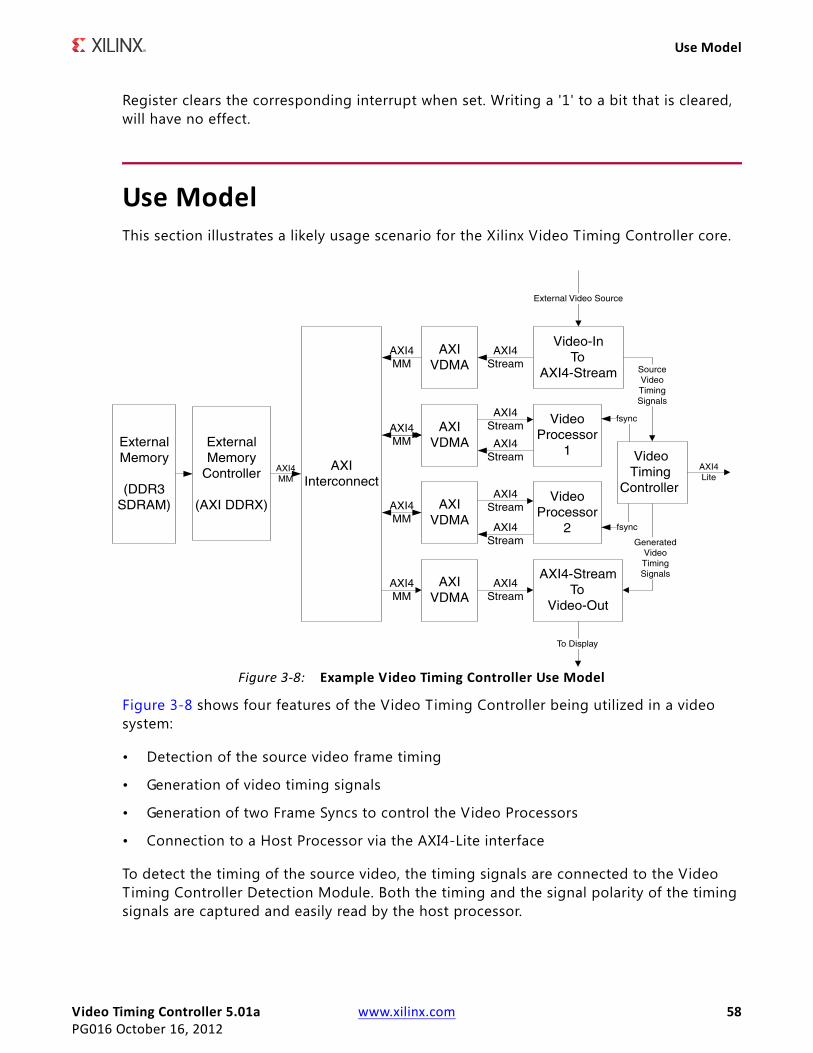
Video Timing Controller 5.01a www.xilinx.com 58PG016 October 16, 2012
Use Model
Register clears the corresponding interrupt when set. Writing a '1' to a bit that is cleared, will have no effect.
Use ModelThis section illustrates a likely usage scenario for the Xilinx Video Timing Controller core.
Figure 3-8 shows four features of the Video Timing Controller being utilized in a video system:
• Detection of the source video frame timing
• Generation of video timing signals
• Generation of two Frame Syncs to control the Video Processors
• Connection to a Host Processor via the AXI4-Lite interface
To detect the timing of the source video, the timing signals are connected to the Video Timing Controller Detection Module. Both the timing and the signal polarity of the timing signals are captured and easily read by the host processor.
X-Ref Target - Figure 3-8
Figure 3-8: Example Video Timing Controller Use Model
Video Timing Controller 5.01a www.xilinx.com 59PG016 October 16, 2012
Clocking
Video timing signals are generated to control a AXI4-Stream to Video-Out module and an external display. The timing of these output signals is controlled by the host processor. The Video Timing Controller can be configured in real-time to replicate the source video format or to slightly change the format on the output, for example, in cases where the input signals are positive polarity yet the display requires negative polarity synchronization signals. The Video Timing Controller can also be reconfigured in real-time to output a completely different format from the input source.
Two Frame Sync outputs are generated to control Video Processor 1 and Video Processor 2. These outputs could be used to control when Video Processor 2 starts processing relative to when Video Processor 1 starts processing. These Frame Syncs can be reconfigured in real-time as well.
The Video Timing Controller is connected to a Host Processor in this example. The AXI4-Lite Interface allows for easy connection between status/control registers and the host processor. In addition, the Video Timing Controller interrupt output can also be used to synchronize the software with hardware events.
If the video system requires that no in-complete video frames are sent from the Video-In To AXI4-Stream core, then the Video Timing Controller must be configured to drive the axis_enable input with bit 8 of the INTC_IF bus. This bus must be enabled with the "Include INTC Interface".
ClockingThe Video Timing Controller core has one clock (clk) that is used to clock the entire core. This includes the AXI4-Lite interface and the core logic.
ResetsThe Video Timing Controller core has one reset (resetn) that is used for the entire core. The reset is active-Low.
Protocol DescriptionThe Video Timing Controller core register interface is compliant with the AXI4-Lite interface.
Video Timing Controller 5.01a www.xilinx.com 60PG016 October 16, 2012
SECTION II: VIVADO DESIGN SUITE
Customizing and Generating the Core
Constraining the Core
Detailed Example Design
Video Timing Controller 5.01a www.xilinx.com 61PG016 October 16, 2012
Chapter 4
Customizing and Generating the CoreThis chapter includes information about using Xilinx tools to customize and generate the core in the Vivado™ Design Suite environment.
Graphical User InterfaceThe Xilinx Video Timing Controller core is easily configured to meet the developer's specific needs through the Vivado tools graphical user interface (Figure 4-1, Figure 4-2). This section provides a quick reference to parameters that can be configured at generation time.
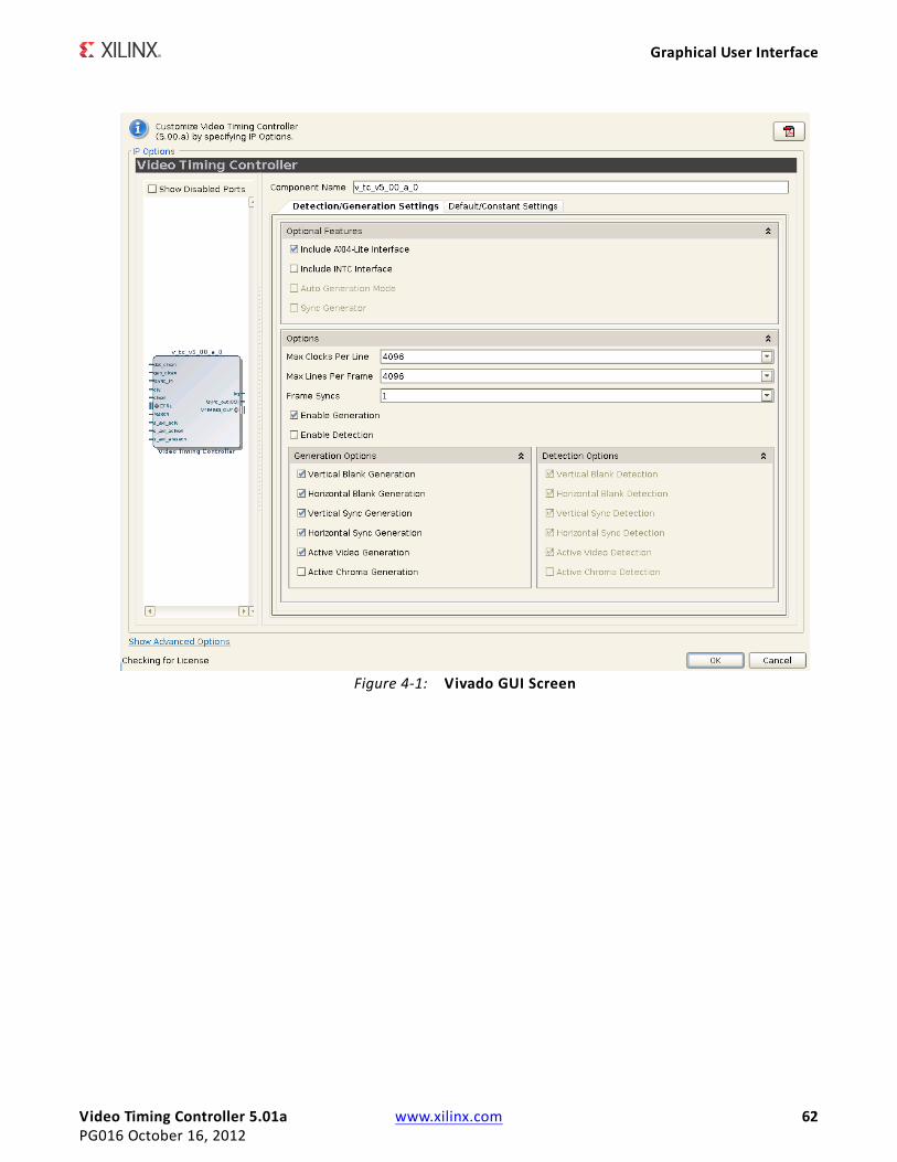
Video Timing Controller 5.01a www.xilinx.com 62PG016 October 16, 2012
Graphical User Interface
X-Ref Target - Figure 4-1
Figure 4-1: Vivado GUI Screen
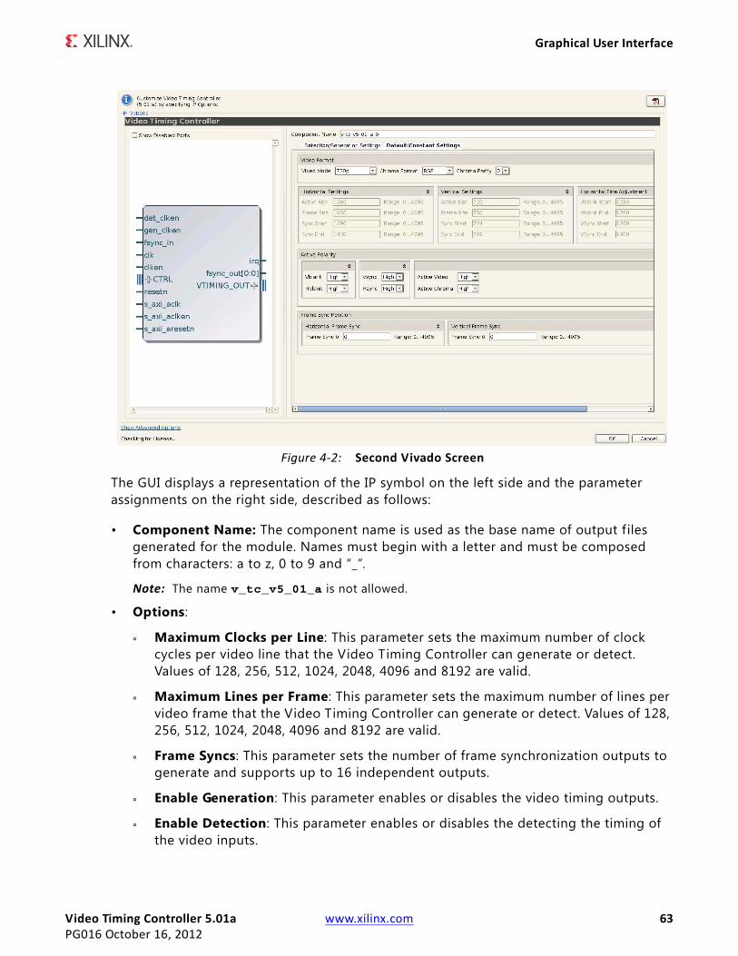
Video Timing Controller 5.01a www.xilinx.com 63PG016 October 16, 2012
Graphical User Interface
The GUI displays a representation of the IP symbol on the left side and the parameter assignments on the right side, described as follows:
• Component Name: The component name is used as the base name of output files generated for the module. Names must begin with a letter and must be composed from characters: a to z, 0 to 9 and “_”.
Note: The name v_tc_v5_01_a is not allowed.
• Options:
° Maximum Clocks per Line: This parameter sets the maximum number of clock cycles per video line that the Video Timing Controller can generate or detect. Values of 128, 256, 512, 1024, 2048, 4096 and 8192 are valid.
° Maximum Lines per Frame: This parameter sets the maximum number of lines per video frame that the Video Timing Controller can generate or detect. Values of 128, 256, 512, 1024, 2048, 4096 and 8192 are valid.
° Frame Syncs: This parameter sets the number of frame synchronization outputs to generate and supports up to 16 independent outputs.
° Enable Generation: This parameter enables or disables the video timing outputs.
° Enable Detection: This parameter enables or disables the detecting the timing of the video inputs.
X-Ref Target - Figure 4-2
Figure 4-2: Second Vivado Screen
Video Timing Controller 5.01a www.xilinx.com 64PG016 October 16, 2012
Graphical User Interface
° Generation Options:
- Synchronize Generator to Detector or to fsync_in: When selected, the timing generator will automatically synchronize to the detector or to the fsync_in input port. Otherwise, the generator will be in free-run mode.
- Auto Generation Mode: When enabled, this parameter will cause the generated video timing outputs to change based on the detected inputs. If this parameter is disabled, the video timing outputs will be generated based on only the f irst detected input format. The output for the generated synchronization signals will continue even if the detection block loses lock. This parameter is available only if both the Enable Generation and Enable Detection parameters are enabled. Note: This parameter has an effect only if one or more of the source select control register bits are set to low.
- Vertical Blank Generation: This parameter enables or disables generating the vertical blank output.
- Horizontal Blank Generation: This parameter enables or disables generating the horizontal blank output.
- Vertical Sync Generation: This parameter enables or disables generating the vertical synchronization output.
- Horizontal Sync Generation: This parameter enables or disables generating the horizontal synchronization output.
- Active Video Generation: This parameter enables or disables generating the active video output.
- Active Chroma Generation: This parameter enables or disables generating the active chroma output.
° Detection Options:
- Vertical Blank Detection: This parameter enables or disables detecting the vertical blank input. If the vblank_in input will not be connected, then the Vertical Blank Detection option must be deselected.
- Horizontal Blank Detection: This parameter enables or disables detecting the horizontal blank input. If the hblank_in input will not be connected, then the Horizontal Blank Detection option must be deselected.
- Vertical Sync Detection: This parameter enables or disables detecting the vertical synchronization input. If the vsync_in input will not be connected, then the Vertical Sync Detection option must be deselected.
- Horizontal Sync Detection: This parameter enables or disables detecting the horizontal synchronization input. If the hsync_in input will not be connected, then the Horizontal Sync Detection option must be deselected.
Video Timing Controller 5.01a www.xilinx.com 65PG016 October 16, 2012
Graphical User Interface
- Active Video Detection: This parameter enables or disables detecting the active video input. If the active_video_in input will not be connected, then the Active Video Detection option must be deselected.
- Active Chroma Detection: This parameter enables or disables detecting the active chroma input. If the active_chroma_in input will not be connected, then the Active Chroma Detection option must be deselected.
• Constant/Default Timing Generation Options:
° Video Format:
- Video Mode: This parameter sets the default video format and controls the Horizontal, Vertical and Horizontal Fine Adjustment settings below. Values of 720p, 480p, 576p, 1080p, 352x288p, 352x576p, 480x576p, 544x575p, 704x576p, 704x480p, 640x480p, 800x600p, 1024x768p, 1280x1024p, 1600x1200p or Custom are valid.
- Chroma Format: This parameter sets the default value of the video format in the GENERATOR ENCODING register at address offset 0x68. This controls the behavior of the active_chroma_out output port.
- Chroma Parity: This parameter sets the default value of the chroma parity in the GENERATOR ENCODING register at address offset 0x68. This controls the behavior of the active_chroma_out output port.
° Horizontal Settings:
- Active Size: This parameter sets the default number of clock cycles per frame (without blanking) in the GENERATOR ACTIVE_SIZE register at address offset 0x060.
- Frame Size: This parameter sets the default number of clock cycles per frame (with blanking) in the GENERATOR HSIZE register at address offset 0x70.
- Sync Start: This parameter sets the default value of the clock cycle count during which the horizontal sync starts in the GENERATOR HSYNC register at address offset 0x78.
- Sync End: This parameter sets the default value of the clock cycle count during which the horizontal sync ends in the GENERATOR HSYNC register at address offset 0x78.
° Vertical Settings:
- Active Size: This parameter sets the default number of lines per frame (without blanking) in the GENERATOR ACTIVE_SIZE register at address offset 0x060.
- Frame Size: This parameter sets the default number of lines per frame size (with blanking) in the GENERATOR VSIZE register at address offset 0x74.
- Sync Start: This parameter sets the default value of the line count during which the vertical sync starts in the GENERATOR F0_VSYNC_V register at address offset 0x80.
Video Timing Controller 5.01a www.xilinx.com 66PG016 October 16, 2012
Graphical User Interface
- Sync End: This parameter sets the default value of the line count during which the vertical sync ends in the GENERATOR F0_VSYNC_V register at address offset 0x80.
° Horizontal Fine Adjustment:
- Vblank Start: This parameter sets the default value of the clock cycle count during which the vertical blank starts in the GENERATOR F0_VBLANK_H register at address offset 0x7C.
- Vblank End: This parameter sets the default value of the clock cycle count during which the vertical blank ends in the GENERATOR F0_VBLANK_H register at address offset 0x7C.
- VSync Start: This parameter sets the default value of the clock cycle count during which the vertical sync starts in the GENERATOR F0_VSYNC_H register at address offset 0x84.
- Vsync End: This parameter sets the default value of the clock cycle count during which the vertical sync ends in the GENERATOR F0_VSYNC_H register at address offset 0x84.
° Active Polarity:
- Vblank : This parameter sets the polarity of the vblank_out signal. Values of Active High or Active Low are valid.
- Hblank : This parameter sets the polarity of the hblank_out signal. Values of Active High or Active Low are valid.
- Vsync: This parameter sets the polarity of the vsync_out signal. Values of Active High or Active Low are valid.
- Hsync: This parameter sets the polarity of the hsync_out signal. Values of Active High or Active Low are valid.
- Active Video: This parameter sets the polarity of the active_video_out signal. Values of Active High or Active Low are valid.
- Active Chroma: This parameter sets the polarity of the active_chroma_out signal. Values of Active High or Active Low are valid.
° Frame Sync Position:
- Frame Sync # Horizontal: These parameters set the default value of the clock cycle count during which Frame Sync # is active in the FRAME SYNC 0-15 CONFIG registers at address offset 0x100-0x13c.
- Frame Sync # Vertical: These parameters set the default value of the line count during which Frame Sync # is active in the FRAME SYNC 0-15 CONFIG registers at address offset 0x100-0x13c.
Note: The parameter values within the Constant/Default Timing Generation Options will also be the values used during timing generation when the Include AXI4-Lite Register Interface parameter is
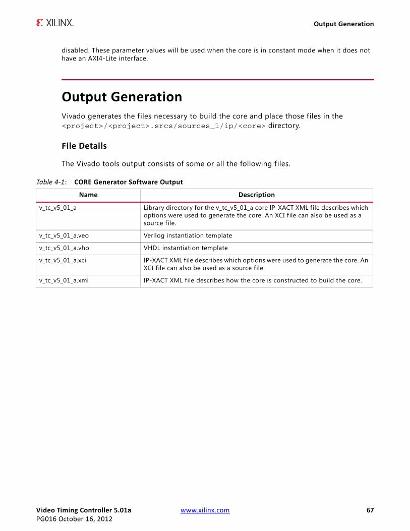
Video Timing Controller 5.01a www.xilinx.com 67PG016 October 16, 2012
Output Generation
disabled. These parameter values will be used when the core is in constant mode when it does not have an AXI4-Lite interface.
Output GenerationVivado generates the files necessary to build the core and place those f iles in the <project>/<project>.srcs/sources_1/ip/<core> directory.
File Details
The Vivado tools output consists of some or all the following files.
Table 4-1: CORE Generator Software Output
Name Description
v_tc_v5_01_a Library directory for the v_tc_v5_01_a core IP-XACT XML file describes which options were used to generate the core. An XCI f ile can also be used as a source f ile.
v_tc_v5_01_a.veo Verilog instantiation template
v_tc_v5_01_a.vho VHDL instantiation template
v_tc_v5_01_a.xci IP-XACT XML file describes which options were used to generate the core. An XCI f ile can also be used as a source f ile.
v_tc_v5_01_a.xml IP-XACT XML file describes how the core is constructed to build the core.
Video Timing Controller 5.01a www.xilinx.com 68PG016 October 16, 2012
Chapter 5
Constraining the Core
Required ConstraintsThe CLK pin should be constrained at the desired pixel clock rate for your video stream. The S_AXI_ACLK pin should be constrained at the frequency of the AXI4-Lite subsystem. In addition to clock frequency, the following constraints should be applied to cover all clock domain crossing data paths.
UCFINST "*U_VIDEO_CTRL*/*SYNC2PROCCLK_I*/data_sync_reg[0]*" TNM = "async_clock_conv_FFDEST";TIMESPEC "TS_async_clock_conv" = FROM FFS TO "async_clock_conv_FFDEST" 2 NS DATAPATHONLY;INST "*U_VIDEO_CTRLk*/*SYNC2VIDCLK_I*/data_sync_reg[0]*" TNM = "vid_async_clock_conv_FFDEST";TIMESPEC "TS_vid_async_clock_conv" = FROM FFS TO "vid_async_clock_conv_FFDEST" 2 NS DATAPATHONLY;
XDC set_max_delay -to [get_cells -hierarchical -match_style ucf "*U_VIDEO_CTRL*/*SYNC2PROCCLK_I*/data_sync_reg[0]*"] -datapath_only 2set_max_delay -to [get_cells -hierarchical -match_style ucf "*U_VIDEO_CTRL*/*SYNC2VIDCLK_I*/data_sync_reg[0]*"] -datapath_only 2
Device, Package, and Speed Grade SelectionsThere are no device, package, or speed grade requirements for this core. For a complete listing of supported devices, see the release notes for this core. For a complete listing of supported devices, see the release notes for this core.

Video Timing Controller 5.01a www.xilinx.com 69PG016 October 16, 2012
Clock Frequencies
Clock FrequenciesThe pixel clock (clk) frequency is the required frequency for this core. See Maximum Frequencies in Chapter 2. The S_AXI_ACLK maximum frequency is the same as the clk maximum.
Clock ManagementThe core automatically handles clock domain crossing between the clk (video pixel clock) and the S_AXI_ACLK (AXI4-Lite) clock domains. The S_AXI_ACLK clock can be slower or faster than the clk clock signal, but must not be more than 128x faster than clk .
Clock PlacementThere are no specific clock placement requirements for this core.
BankingThere are no specific Banking rules for this core.
Transceiver PlacementThere are no Transceiver Placement requirements for this core.
I/O Standard and PlacementThere are no specific I/O standards and placement requirements for this core.
Video Timing Controller 5.01a www.xilinx.com 70PG016 October 16, 2012
Chapter 6
Detailed Example DesignNo example design is available at the time for the LogiCORE IP Video Timing Controller v5.01a core.
Demonstration Test BenchA demonstration test bench is provided with the core which enables you to observe core behavior in a typical scenario. This test bench is generated together with the core in Vivado design tools. You are encouraged to make simple modifications to the configurations and observe the changes in the waveform.
Generating the Test Bench1. After customizing the IP, right-click on the core instance in Sources pane and select
Generate Output Products (Figure 6-1).
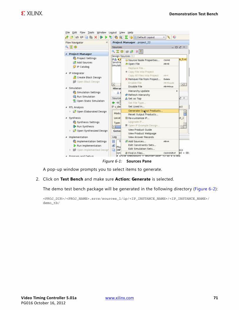
Video Timing Controller 5.01a www.xilinx.com 71PG016 October 16, 2012
Demonstration Test Bench
A pop-up window prompts you to select items to generate.
2. Click on Test Bench and make sure Action: Generate is selected.
The demo test bench package will be generated in the following directory (Figure 6-2):
<PROJ_DIR>/<PROJ_NAME>.srcs/sources_1/ip/<IP_INSTANCE_NAME>/<IP_INSTANCE_NAME>/demo_tb/
X-Ref Target - Figure 6-1
Figure 6-1: Sources Pane
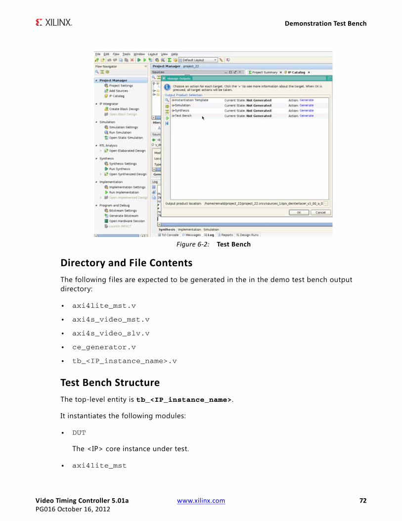
Video Timing Controller 5.01a www.xilinx.com 72PG016 October 16, 2012
Demonstration Test Bench
Directory and File ContentsThe following files are expected to be generated in the in the demo test bench output directory:
• axi4lite_mst.v
• axi4s_video_mst.v
• axi4s_video_slv.v
• ce_generator.v
• tb_<IP_instance_name>.v
Test Bench StructureThe top-level entity is tb_<IP_instance_name>.
It instantiates the following modules:
• DUT
The <IP> core instance under test.
• axi4lite_mst
X-Ref Target - Figure 6-2
Figure 6-2: Test Bench
Video Timing Controller 5.01a www.xilinx.com 73PG016 October 16, 2012
Demonstration Test Bench
The AXI4-Lite master module, which initiates AXI4-Lite transactions to program core registers.
• axi4s_video_mst
The AXI4-Stream master module, which generates ramp data and initiates AXI4-Stream transactions to provide video stimuli for the core and can also be used to open stimuli f iles generated from the reference C-models and convert them into corresponding AXI4-Stream transactions.
To do this, edit tb_<IP_instance_name>.v:
a. Add define macro for the stimuli f ile name and directory pathdefine STIMULI_FILE_NAME<path><filename>.
b. Comment-out/remove the following line:MST.is_ramp_gen(`C_ACTIVE_ROWS, `C_ACTIVE_COLS, 2);and replace with the following line:MST.use_file(`STIMULI_FILE_NAME);
For information on how to generate stimuli f iles, refer to C Model Reference.
• axi4s_video_slv
The AXI4-Stream slave module, which acts as a passive slave to provide handshake signals for the AXI4-Stream transactions from the core's output, can be used to open the data files generated from the reference C-model and verify the output from the core.
To do this, edit tb_<IP_instance_name>.v:
a. Add define macro for the golden f ile name and directory pathdefine GOLDEN_FILE_NAME “<path><filename>”.
b. Comment-out the following line:SLV.is_passive;and replace with the following line:SLV.use_file(`GOLDEN_FILE_NAME);
For information on how to generate golden f iles, refer to C Model Reference.
• ce_gen
Programmable Clock Enable (ACLKEN) generator.
Running the SimulationThere are two ways to run the demonstration test bench.
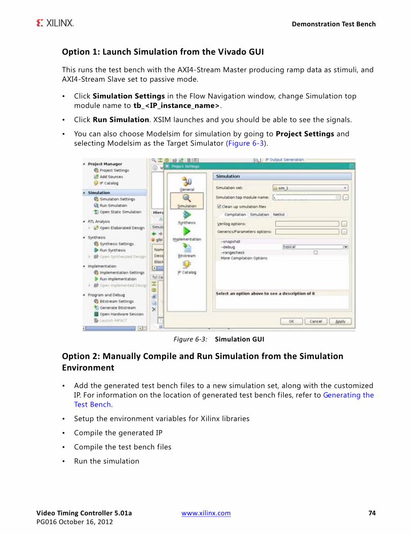
Video Timing Controller 5.01a www.xilinx.com 74PG016 October 16, 2012
Demonstration Test Bench
Option 1: Launch Simulation from the Vivado GUI
This runs the test bench with the AXI4-Stream Master producing ramp data as stimuli, and AXI4-Stream Slave set to passive mode.
• Click Simulation Settings in the Flow Navigation window, change Simulation top module name to tb_<IP_instance_name>.
• Click Run Simulation. XSIM launches and you should be able to see the signals.
• You can also choose Modelsim for simulation by going to Project Settings and selecting Modelsim as the Target Simulator (Figure 6-3).
Option 2: Manually Compile and Run Simulation from the Simulation Environment
• Add the generated test bench files to a new simulation set, along with the customized IP. For information on the location of generated test bench files, refer to Generating the Test Bench.
• Setup the environment variables for Xilinx libraries
• Compile the generated IP
• Compile the test bench files
• Run the simulation
X-Ref Target - Figure 6-3
Figure 6-3: Simulation GUI
Video Timing Controller 5.01a www.xilinx.com 75PG016 October 16, 2012
Demonstration Test Bench
RECOMMENDED: Change the default simulation time from 1000 ns to all to be able observe a full frame transaction.
Video Timing Controller 5.01a www.xilinx.com 76PG016 October 16, 2012
SECTION III: ISE DESIGN SUITE
Customizing and Generating the Core
Constraining the Core
Detailed Example Design
Video Timing Controller 5.01a www.xilinx.com 77PG016 October 16, 2012
Chapter 7
Customizing and Generating the CoreThis chapter includes information about using Xilinx tools to customize and generate the core in the ISE® Design Suite environment.
Graphical User InterfaceThe Xilinx Video Timing Controller core is easily configured to meet the developer's specific needs through the CORE Generator graphical user interface (Figure 7-1, Figure 7-2), or through the EDK GUI (Figure 7-3). This section provides a quick reference to parameters that can be configured at generation time.
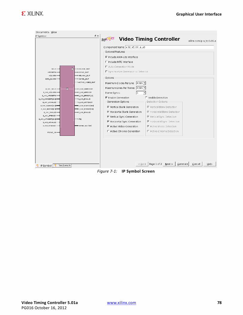
Video Timing Controller 5.01a www.xilinx.com 78PG016 October 16, 2012
Graphical User Interface
X-Ref Target - Figure 7-1
Figure 7-1: IP Symbol Screen
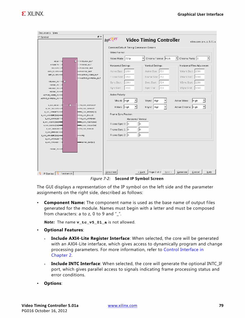
Video Timing Controller 5.01a www.xilinx.com 79PG016 October 16, 2012
Graphical User Interface
The GUI displays a representation of the IP symbol on the left side and the parameter assignments on the right side, described as follows:
• Component Name: The component name is used as the base name of output files generated for the module. Names must begin with a letter and must be composed from characters: a to z, 0 to 9 and “_”.
Note: The name v_tc_v5_01_a is not allowed.
• Optional Features:
° Include AXI4-Lite Register Interface: When selected, the core will be generated with an AXI4-Lite interface, which gives access to dynamically program and change processing parameters. For more information, refer to Control Interface in Chapter 2.
° Include INTC Interface: When selected, the core will generate the optional INTC_IF port, which gives parallel access to signals indicating frame processing status and error conditions.
• Options:
X-Ref Target - Figure 7-2
Figure 7-2: Second IP Symbol Screen
Video Timing Controller 5.01a www.xilinx.com 80PG016 October 16, 2012
Graphical User Interface
° Maximum Clocks per Line: This parameter sets the maximum number of clock cycles per video line that the Video Timing Controller can generate or detect. Values of 128, 256, 512, 1024, 2048, 4096 and 8192 are valid.
° Maximum Lines per Frame: This parameter sets the maximum number of lines per video frame that the Video Timing Controller can generate or detect. Values of 128, 256, 512, 1024, 2048, 4096 and 8192 are valid.
° Frame Syncs: This parameter sets the number of frame synchronization outputs to generate and supports up to 16 independent outputs.
° Enable Generation: This parameter enables or disables the video timing outputs.
° Enable Detection: This parameter enables or disables the detecting the timing of the video inputs.
° Generation Options:
- Synchronize Generator to Detector or to fsync_in: When selected, the timing generator will automatically synchronize to the detector or to the fsync_in input port. Otherwise, the generator will be in free-run mode.
- Auto Generation Mode: When enabled, this parameter will cause the generated video timing outputs to change based on the detected inputs. If this parameter is disabled, the video timing outputs will be generated based on only the f irst detected input format. The output for the generated synchronization signals will continue even if the detection block loses lock. This parameter is available only if both the Enable Generation and Enable Detection parameters are enabled. Note: This parameter has an effect only if one or more of the source select control register bits are set to low.
- Vertical Blank Generation: This parameter enables or disables generating the vertical blank output.
- Horizontal Blank Generation: This parameter enables or disables generating the horizontal blank output.
- Vertical Sync Generation: This parameter enables or disables generating the vertical synchronization output.
- Horizontal Sync Generation: This parameter enables or disables generating the horizontal synchronization output.
- Active Video Generation: This parameter enables or disables generating the active video output.
- Active Chroma Generation: This parameter enables or disables generating the active chroma output.
° Detection Options:
- Vertical Blank Detection: This parameter enables or disables detecting the vertical blank input. If the vblank_in input will not be connected, then the Vertical Blank Detection option must be deselected.
Video Timing Controller 5.01a www.xilinx.com 81PG016 October 16, 2012
Graphical User Interface
- Horizontal Blank Detection: This parameter enables or disables detecting the horizontal blank input. If the hblank_in input will not be connected, then the Horizontal Blank Detection option must be deselected.
- Vertical Sync Detection: This parameter enables or disables detecting the vertical synchronization input. If the vsync_in input will not be connected, then the Vertical Sync Detection option must be deselected.
- Horizontal Sync Detection: This parameter enables or disables detecting the horizontal synchronization input. If the hsync_in input will not be connected, then the Horizontal Sync Detection option must be deselected.
- Active Video Detection: This parameter enables or disables detecting the active video input. If the active_video_in input will not be connected, then the Active Video Detection option must be deselected.
- Active Chroma Detection: This parameter enables or disables detecting the active chroma input. If the active_chroma_in input will not be connected, then the Active Chroma Detection option must be deselected.
• Constant/Default Timing Generation Options:
° Video Format:
- Video Mode: This parameter sets the default video format and controls the Horizontal, Vertical and Horizontal Fine Adjustment settings below. Values of 720p, 480p, 576p, 1080p, 352x288p, 352x576p, 480x576p, 544x575p, 704x576p, 704x480p, 640x480p, 800x600p, 1024x768p, 1280x1024p, 1600x1200p or Custom are valid.
- Chroma Format: This parameter sets the default value of the video format in the GENERATOR ENCODING register at address offset 0x68. This controls the behavior of the active_chroma_out output port.
- Chroma Parity: This parameter sets the default value of the chroma parity in the GENERATOR ENCODING register at address offset 0x68. This controls the behavior of the active_chroma_out output port.
° Horizontal Settings:
- Active Size: This parameter sets the default number of clock cycles per frame (without blanking) in the GENERATOR ACTIVE_SIZE register at address offset 0x060.
- Frame Size: This parameter sets the default number of clock cycles per frame (with blanking) in the GENERATOR HSIZE register at address offset 0x70.
- Sync Start: This parameter sets the default value of the clock cycle count during which the horizontal sync starts in the GENERATOR HSYNC register at address offset 0x78.
Video Timing Controller 5.01a www.xilinx.com 82PG016 October 16, 2012
Graphical User Interface
- Sync End: This parameter sets the default value of the clock cycle count during which the horizontal sync ends in the GENERATOR HSYNC register at address offset 0x78.
° Vertical Settings:
- Active Size: This parameter sets the default number of lines per frame (without blanking) in the GENERATOR ACTIVE_SIZE register at address offset 0x060.
- Frame Size: This parameter sets the default number of lines per frame size (with blanking) in the GENERATOR VSIZE register at address offset 0x74.
- Sync Start: This parameter sets the default value of the line count during which the vertical sync starts in the GENERATOR F0_VSYNC_V register at address offset 0x80.
- Sync End: This parameter sets the default value of the line count during which the vertical sync ends in the GENERATOR F0_VSYNC_V register at address offset 0x80.
° Horizontal Fine Adjustment:
- Vblank Start: This parameter sets the default value of the clock cycle count during which the vertical blank starts in the GENERATOR F0_VBLANK_H register at address offset 0x7C.
- Vblank End: This parameter sets the default value of the clock cycle count during which the vertical blank ends in the GENERATOR F0_VBLANK_H register at address offset 0x7C.
- VSync Start: This parameter sets the default value of the clock cycle count during which the vertical sync starts in the GENERATOR F0_VSYNC_H register at address offset 0x84.
- Vsync End: This parameter sets the default value of the clock cycle count during which the vertical sync ends in the GENERATOR F0_VSYNC_H register at address offset 0x84.
° Active Polarity:
- Vblank : This parameter sets the polarity of the vblank_out signal. Values of Active High or Active Low are valid.
- Hblank : This parameter sets the polarity of the hblank_out signal. Values of Active High or Active Low are valid.
- Vsync: This parameter sets the polarity of the vsync_out signal. Values of Active High or Active Low are valid.
- Hsync: This parameter sets the polarity of the hsync_out signal. Values of Active High or Active Low are valid.
- Active Video: This parameter sets the polarity of the active_video_out signal. Values of Active High or Active Low are valid.
Video Timing Controller 5.01a www.xilinx.com 83PG016 October 16, 2012
Graphical User Interface
- Active Chroma: This parameter sets the polarity of the active_chroma_out signal. Values of Active High or Active Low are valid.
° Frame Sync Position:
- Frame Sync # Horizontal: These parameters set the default value of the clock cycle count during which Frame Sync # is active in the FRAME SYNC 0-15 CONFIG registers at address offset 0x100-0x13c.
- Frame Sync # Vertical: These parameters set the default value of the line count during which Frame Sync # is active in the FRAME SYNC 0-15 CONFIG registers at address offset 0x100-0x13c.
Note: The parameter values within the Constant/Default Timing Generation Options will also be the values used during timing generation when the Include AXI4-Lite Register Interface parameter is disabled. These parameter values will be used when the core is in constant mode when it does not have an AXI4-Lite interface.
EDK pCore Graphical User Interface When the Xilinx Video Timing Controller core is generated from the EDK software as an EDK pCore, it is generated with each option set to the default value. All customization s of a Video Timing Controller pCore are done with the EDK pCore graphical user interface (GUI). Figure 7-3 illustrates the EDK pCore GUI for the Video Timing Controller pCore. All of the options in the EDK pCore GUI for the Video Timing Controller core correspond to the same options in the CORE Generator software GUI. See Graphical User Interface for details about each option.
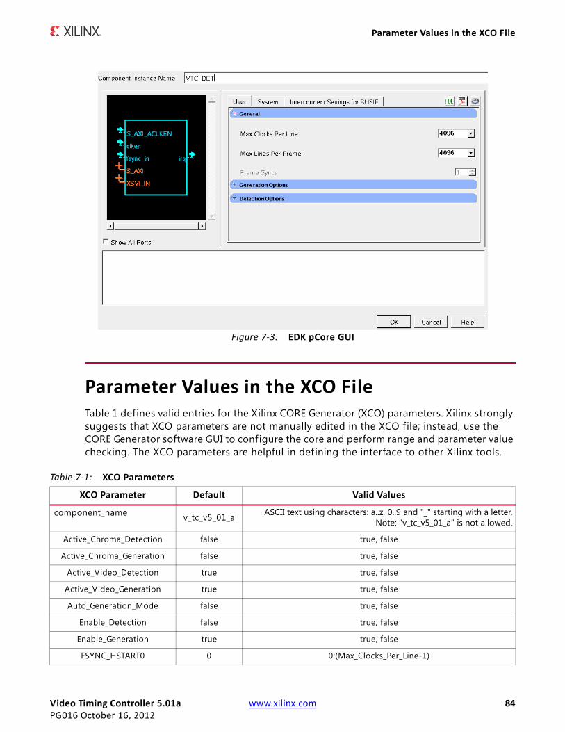
Video Timing Controller 5.01a www.xilinx.com 84PG016 October 16, 2012
Parameter Values in the XCO File
Parameter Values in the XCO FileTable 1 defines valid entries for the Xilinx CORE Generator (XCO) parameters. Xilinx strongly suggests that XCO parameters are not manually edited in the XCO file; instead, use the CORE Generator software GUI to configure the core and perform range and parameter value checking. The XCO parameters are helpful in defining the interface to other Xilinx tools.
X-Ref Target - Figure 7-3
Figure 7-3: EDK pCore GUI
Table 7-1: XCO Parameters
XCO Parameter Default Valid Values
component_name v_tc_v5_01_a ASCII text using characters: a..z, 0..9 and "_" starting with a letter.Note: "v_tc_v5_01_a" is not allowed.
Active_Chroma_Detection false true, false
Active_Chroma_Generation false true, false
Active_Video_Detection true true, false
Active_Video_Generation true true, false
Auto_Generation_Mode false true, false
Enable_Detection false true, false
Enable_Generation true true, false
FSYNC_HSTART0 0 0:(Max_Clocks_Per_Line-1)
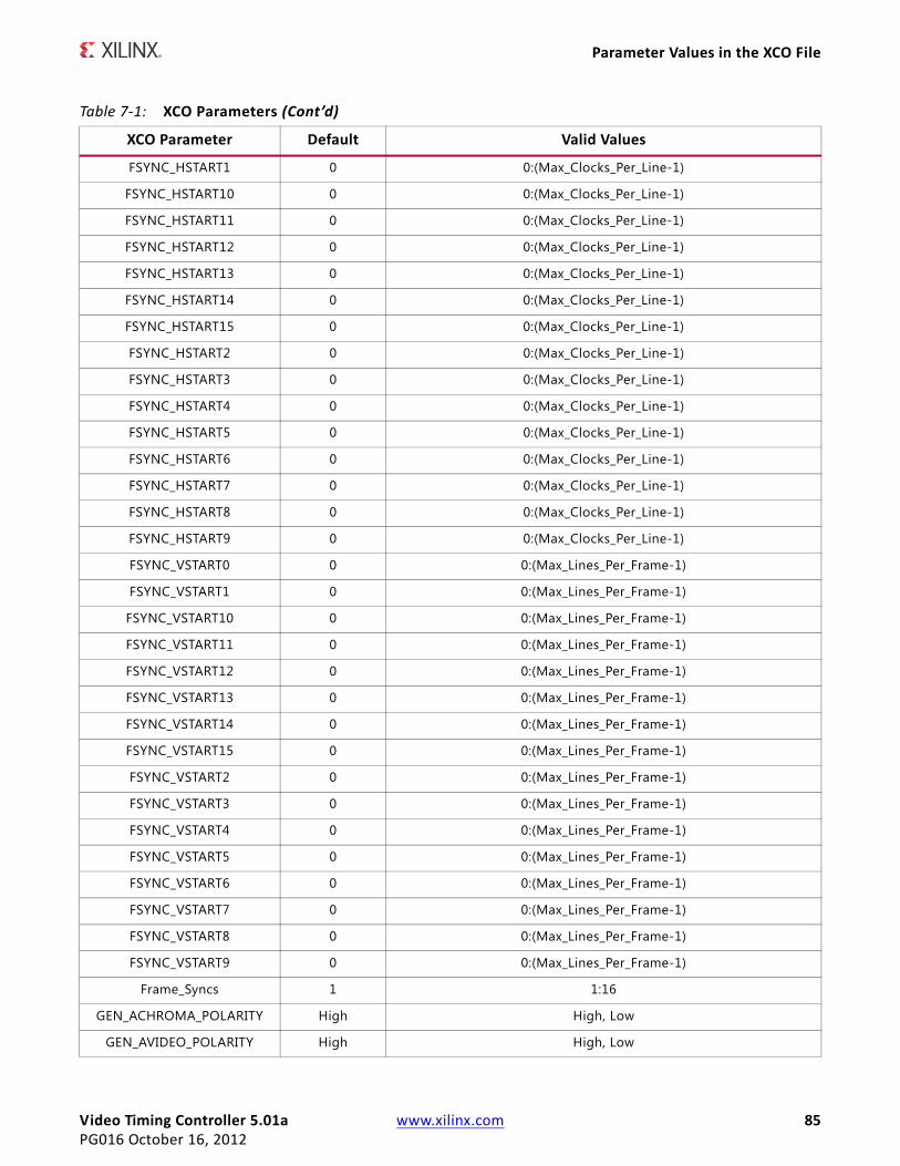
Video Timing Controller 5.01a www.xilinx.com 85PG016 October 16, 2012
Parameter Values in the XCO File
FSYNC_HSTART1 0 0:(Max_Clocks_Per_Line-1)
FSYNC_HSTART10 0 0:(Max_Clocks_Per_Line-1)
FSYNC_HSTART11 0 0:(Max_Clocks_Per_Line-1)
FSYNC_HSTART12 0 0:(Max_Clocks_Per_Line-1)
FSYNC_HSTART13 0 0:(Max_Clocks_Per_Line-1)
FSYNC_HSTART14 0 0:(Max_Clocks_Per_Line-1)
FSYNC_HSTART15 0 0:(Max_Clocks_Per_Line-1)
FSYNC_HSTART2 0 0:(Max_Clocks_Per_Line-1)
FSYNC_HSTART3 0 0:(Max_Clocks_Per_Line-1)
FSYNC_HSTART4 0 0:(Max_Clocks_Per_Line-1)
FSYNC_HSTART5 0 0:(Max_Clocks_Per_Line-1)
FSYNC_HSTART6 0 0:(Max_Clocks_Per_Line-1)
FSYNC_HSTART7 0 0:(Max_Clocks_Per_Line-1)
FSYNC_HSTART8 0 0:(Max_Clocks_Per_Line-1)
FSYNC_HSTART9 0 0:(Max_Clocks_Per_Line-1)
FSYNC_VSTART0 0 0:(Max_Lines_Per_Frame-1)
FSYNC_VSTART1 0 0:(Max_Lines_Per_Frame-1)
FSYNC_VSTART10 0 0:(Max_Lines_Per_Frame-1)
FSYNC_VSTART11 0 0:(Max_Lines_Per_Frame-1)
FSYNC_VSTART12 0 0:(Max_Lines_Per_Frame-1)
FSYNC_VSTART13 0 0:(Max_Lines_Per_Frame-1)
FSYNC_VSTART14 0 0:(Max_Lines_Per_Frame-1)
FSYNC_VSTART15 0 0:(Max_Lines_Per_Frame-1)
FSYNC_VSTART2 0 0:(Max_Lines_Per_Frame-1)
FSYNC_VSTART3 0 0:(Max_Lines_Per_Frame-1)
FSYNC_VSTART4 0 0:(Max_Lines_Per_Frame-1)
FSYNC_VSTART5 0 0:(Max_Lines_Per_Frame-1)
FSYNC_VSTART6 0 0:(Max_Lines_Per_Frame-1)
FSYNC_VSTART7 0 0:(Max_Lines_Per_Frame-1)
FSYNC_VSTART8 0 0:(Max_Lines_Per_Frame-1)
FSYNC_VSTART9 0 0:(Max_Lines_Per_Frame-1)
Frame_Syncs 1 1:16
GEN_ACHROMA_POLARITY High High, Low
GEN_AVIDEO_POLARITY High High, Low
Table 7-1: XCO Parameters (Cont’d)
XCO Parameter Default Valid Values
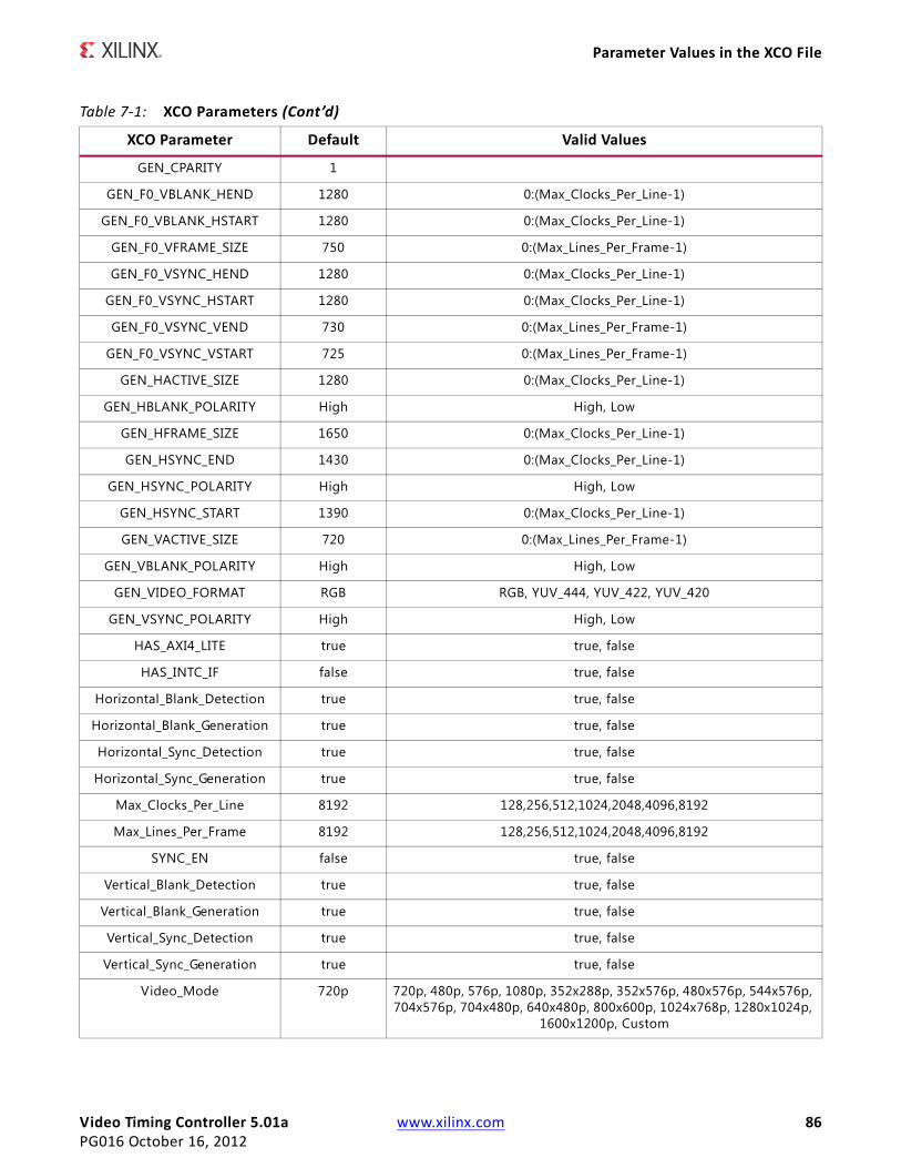
Video Timing Controller 5.01a www.xilinx.com 86PG016 October 16, 2012
Parameter Values in the XCO File
GEN_CPARITY 1
GEN_F0_VBLANK_HEND 1280 0:(Max_Clocks_Per_Line-1)
GEN_F0_VBLANK_HSTART 1280 0:(Max_Clocks_Per_Line-1)
GEN_F0_VFRAME_SIZE 750 0:(Max_Lines_Per_Frame-1)
GEN_F0_VSYNC_HEND 1280 0:(Max_Clocks_Per_Line-1)
GEN_F0_VSYNC_HSTART 1280 0:(Max_Clocks_Per_Line-1)
GEN_F0_VSYNC_VEND 730 0:(Max_Lines_Per_Frame-1)
GEN_F0_VSYNC_VSTART 725 0:(Max_Lines_Per_Frame-1)
GEN_HACTIVE_SIZE 1280 0:(Max_Clocks_Per_Line-1)
GEN_HBLANK_POLARITY High High, Low
GEN_HFRAME_SIZE 1650 0:(Max_Clocks_Per_Line-1)
GEN_HSYNC_END 1430 0:(Max_Clocks_Per_Line-1)
GEN_HSYNC_POLARITY High High, Low
GEN_HSYNC_START 1390 0:(Max_Clocks_Per_Line-1)
GEN_VACTIVE_SIZE 720 0:(Max_Lines_Per_Frame-1)
GEN_VBLANK_POLARITY High High, Low
GEN_VIDEO_FORMAT RGB RGB, YUV_444, YUV_422, YUV_420
GEN_VSYNC_POLARITY High High, Low
HAS_AXI4_LITE true true, false
HAS_INTC_IF false true, false
Horizontal_Blank_Detection true true, false
Horizontal_Blank_Generation true true, false
Horizontal_Sync_Detection true true, false
Horizontal_Sync_Generation true true, false
Max_Clocks_Per_Line 8192 128,256,512,1024,2048,4096,8192
Max_Lines_Per_Frame 8192 128,256,512,1024,2048,4096,8192
SYNC_EN false true, false
Vertical_Blank_Detection true true, false
Vertical_Blank_Generation true true, false
Vertical_Sync_Detection true true, false
Vertical_Sync_Generation true true, false
Video_Mode 720p 720p, 480p, 576p, 1080p, 352x288p, 352x576p, 480x576p, 544x576p, 704x576p, 704x480p, 640x480p, 800x600p, 1024x768p, 1280x1024p,
1600x1200p, Custom
Table 7-1: XCO Parameters (Cont’d)
XCO Parameter Default Valid Values
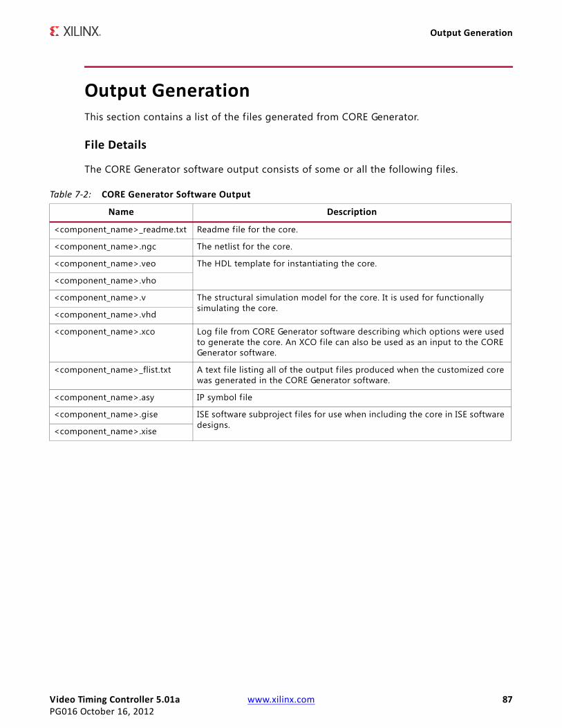
Video Timing Controller 5.01a www.xilinx.com 87PG016 October 16, 2012
Output Generation
Output GenerationThis section contains a list of the f iles generated from CORE Generator.
File Details
The CORE Generator software output consists of some or all the following files.
Table 7-2: CORE Generator Software Output
Name Description
<component_name>_readme.txt Readme file for the core.
<component_name>.ngc The netlist for the core.
<component_name>.veo The HDL template for instantiating the core.
<component_name>.vho
<component_name>.v The structural simulation model for the core. It is used for functionally simulating the core.
<component_name>.vhd
<component_name>.xco Log file from CORE Generator software describing which options were used to generate the core. An XCO file can also be used as an input to the CORE Generator software.
<component_name>_flist.txt A text f ile listing all of the output files produced when the customized core was generated in the CORE Generator software.
<component_name>.asy IP symbol f ile
<component_name>.gise ISE software subproject f iles for use when including the core in ISE software designs.
<component_name>.xise
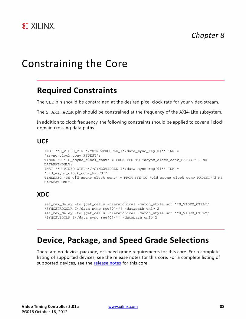
Video Timing Controller 5.01a www.xilinx.com 88PG016 October 16, 2012
Chapter 8
Constraining the Core
Required ConstraintsThe CLK pin should be constrained at the desired pixel clock rate for your video stream.
The S_AXI_ACLK pin should be constrained at the frequency of the AXI4-Lite subsystem.
In addition to clock frequency, the following constraints should be applied to cover all clock domain crossing data paths.
UCFINST "*U_VIDEO_CTRL*/*SYNC2PROCCLK_I*/data_sync_reg[0]*" TNM = "async_clock_conv_FFDEST";TIMESPEC "TS_async_clock_conv" = FROM FFS TO "async_clock_conv_FFDEST" 2 NS DATAPATHONLY;INST "*U_VIDEO_CTRLk*/*SYNC2VIDCLK_I*/data_sync_reg[0]*" TNM = "vid_async_clock_conv_FFDEST";TIMESPEC "TS_vid_async_clock_conv" = FROM FFS TO "vid_async_clock_conv_FFDEST" 2 NS DATAPATHONLY;
XDC set_max_delay -to [get_cells -hierarchical -match_style ucf "*U_VIDEO_CTRL*/*SYNC2PROCCLK_I*/data_sync_reg[0]*"] -datapath_only 2set_max_delay -to [get_cells -hierarchical -match_style ucf "*U_VIDEO_CTRL*/*SYNC2VIDCLK_I*/data_sync_reg[0]*"] -datapath_only 2
Device, Package, and Speed Grade SelectionsThere are no device, package, or speed grade requirements for this core. For a complete listing of supported devices, see the release notes for this core. For a complete listing of supported devices, see the release notes for this core.
Video Timing Controller 5.01a www.xilinx.com 89PG016 October 16, 2012
Clock Frequencies
Clock FrequenciesThe pixel clock (clk) frequency is the required frequency for this core. See Maximum Frequencies in Chapter 2. The S_AXI_ACLK maximum frequency is the same as the clk maximum.
Clock ManagementThe core automatically handles clock domain crossing between the clk (video pixel clock) and the S_AXI_ACLK (AXI4-Lite) clock domains. The S_AXI_ACLK clock can be slower or faster than the clk clock signal, but must not be more than 128x faster than clk .
Clock PlacementThere are no specific clock placement requirements for this core.
BankingThere are no specific Banking rules for this core.
Transceiver PlacementThere are no Transceiver Placement requirements for this core.
I/O Standard and PlacementThere are no specific I/O standards and placement requirements for this core.
Video Timing Controller 5.01a www.xilinx.com 90PG016 October 16, 2012
Chapter 9
Detailed Example DesignNo example design is available at the time for the LogiCORE IP Video Timing Controller v5.01a core.
Demonstration Test BenchA demonstration test bench is provided which enables core users to observe core behavior in a typical use scenario. The user is encouraged to make simple modif ications to the test conditions and observe the changes in the waveform.
Test Bench StructureThe top-level entity, tb_main.v, instantiates the following modules:
• DUT
The TC core instance under test.
• axi4lite_mst
The AXI4-Lite master module, which initiates AXI4-Lite transactions to program core registers.
• axi4s_video_mst
The AXI4-Stream master module, which opens the stimuli txt f ile and initiates AXI4-Stream transactions to provide stimuli data for the core. The test bench automatically translates the AXI4-Stream into video timing including blanks and sync.
• axi4s_video_slv
The AXI4-Stream slave module, which opens the result txt f ile and verif ies transactions from the core
• ce_gen
Video Timing Controller 5.01a www.xilinx.com 91PG016 October 16, 2012
Running the Simulation
Programmable Clock Enable (clken) generator
Running the Simulation• Simulation using ModelSim for Linux:
From the console, Type "source run_mti.sh".
• Simulation using iSim for Linux:From the console, Type "source run_isim.sh".
• Simulation using ModelSim for Windows: Double-click on "run_mti.bat" f ile.
• Simulation using iSim: Double-click on "run_isim.bat" f ile.
Directory and File ContentsThe directory structure underneath the top-level folder is:
• expected:Contains the pre-generated expected/golden data used by the test bench to compare actual output data.
• stimuli: Contains the pre-generated input data used by the test bench to stimulate the core (including register programming values).
• Results:Actual output data will be written to a file in this folder.
• Src:Contains the .vhd simulation files and the .xco CORE Generator parameterization f ile of the core instance. The .vhd f ile is a netlist generated using CORE Generator. The .xco f ile can be used to regenerate a new netlist using CORE Generator.
The available core C-model can be used to generate stimuli and expected results for any user bmp image. For more information, refer to Chapter 4, C Model Reference.
The top-level directory contains packages and Verilog modules used by the test bench, as well as:
• isim_wave.wcfg:Waveform configuration for ISIM
Video Timing Controller 5.01a www.xilinx.com 92PG016 October 16, 2012
Directory and File Contents
• mti_wave.do: Waveform configuration for ModelSim
• run_isim.bat :Runscript for iSim in Windows
• run_isim.sh:Runscript for iSim in Linux
• run_mti.bat:Runscript for ModelSim in Windows
• run_mti.sh:Runscript for ModelSim in Linux
Video Timing Controller 5.01a www.xilinx.com 93PG016 October 16, 2012
SECTION IV: APPENDICES
Verification, Compliance, and Interoperability
Migrating
Debugging
Additional Resources
Video Timing Controller 5.01a www.xilinx.com 94PG016 October 16, 2012
Appendix A
Verification, Compliance, and Interoperability
SimulationA highly parameterizable test bench was used to test the Video Timing Controller core. Testing included the following:
• Register accesses
• Processing of multiple frames of data
• Testing of various frame sizes including 1080p, 720p, and 480p
• Varying instantiations of the core
• Varying the polarity of input and output signals
• Varying the horizontal offset of the vertical timing signals
• Regenerating the input on the output
• Testing of various interrupts
Hardware TestingThe Video Timing Controller core has been tested in a variety of hardware platforms at Xilinx to represent a variety of parameterizations, including the following:
• A test design was developed for the core that incorporated a MicroBlaze™ processor, AXI4 Interconnect and various other peripherals. The software for the test system included live video input for the Video Timing Controller core. The Video Timing Controller, in addition to live video, was also connected in loopback allow the generator to feed the detector for a robust loopback test. Various tests could be supported by varying the configuration of the Timing Controller core or by loading a different software executable. The MicroBlaze processor was responsible for:
° Initializing the appropriate input and output buffers in external memory.
Video Timing Controller 5.01a www.xilinx.com 95PG016 October 16, 2012
Hardware Testing
° Initializing the Video Timing Controller core.
° Initializing the HDMI/DVI input and output cores for live video.
° Launching the test.
° Configuring the Video Timing Controller for various input frame sizes and checking the detection/generation loopback connection for correct video detection
° Controlling the peripherals including the UART and AXI VDMAs.
Video Timing Controller 5.01a www.xilinx.com 96PG016 October 16, 2012
Appendix B
MigratingFor information about migration from ISE Design Suite to Vivado Design Suite, see Vivado Design Suite Migration Methodology Guide (UG911) [Ref 2].
For a complete list of Vivado User and Methodology Guides, see the Vivado Design Suite - 2012.3 User Guides web page.
Migrating to the AXI4-Lite InterfaceThe Video Timing Controller v4.00.a changed from the PLB processor interface to the EDK pCore AXI4-Lite interface. As a result, all of the PLB-related connections have been replaced with an AXI4-Lite interface. For more information, see the AXI Reference Guide at:www.xilinx.com/support/documentation/ip_documentation/ug761_axi_reference_guide.pdf
Parameter Changes in the XCO FileThe Video Timing Controller v5.00.a added the following parameters in the .xco f ile:
• GEN_ACHROMA_POLARITY
• GEN_AVIDEO_POLARITY
• GEN_CPARITY
• GEN_F0_VBLANK_HEND
• GEN_F0_VBLANK_HSTART
• GEN_F0_VFRAME_SIZE
• GEN_F0_VSYNC_HEND
• GEN_F0_VSYNC_HSTART
• GEN_F0_VSYNC_VEND
• GEN_F0_VSYNC_VSTART
Video Timing Controller 5.01a www.xilinx.com 97PG016 October 16, 2012
Port Changes
• GEN_HACTIVE_SIZE
• GEN_HBLANK_POLARITY
• GEN_HFRAME_SIZE
• GEN_HSYNC_END
• GEN_HSYNC_POLARITY
• GEN_HSYNC_START
• GEN_VACTIVE_SIZE
• GEN_VBLANK_POLARITY
• GEN_VIDEO_FORMAT
• GEN_VSYNC_POLARITY
• HAS_AXI4_LITE
• HAS_INTC_IF
• SYNC_EN
• Video_Mode
Port ChangesThe Video Timing Controller v5.00.a removed all GPP interface ports. The Video Timing Controller v4.00.a.0 added the ability to operate on video frame sizes up to 8192 x 8192. Previous versions supported 4096 x 4096 maximum. If the maximum sizes of 8192 are selected, some GPP ports will be 13 bits wide where on previous versions of the core, these ports were 12 bits.
The Video Timing Controller v4.00.a also added the ability to detect and generate vertical signals with a horizontal offset. In order to report the horizontal start cycle of these vertical signals, the Video Timing Controller v4.00.a added the following new ports:
• gen_v0blank_hstart
• gen_v0blank_hend
• gen_v0sync_hstart
• gen_v0sync_hend
• det_v0blank_hstart
• det_v0blank_hend
• det_v0sync_hstart
Video Timing Controller 5.01a www.xilinx.com 98PG016 October 16, 2012
Functionality Changes
• det_v0sync_hend
Functionality ChangesThe Video Timing Controller v5.00.a AXI4-Lite register definitions changed from the previous version, simplifying the address map. The Video Timing Controller v5.00.a also added parameters for configuring the core in constant mode, thus the core can be initialized to generate timing after reset without a processor or software. The Video Timing Controller v3.0 added the ability to operate on video frame sizes up to 8192 x 8192. Previous versions supported 4096 x 4096 maximum.
The Video Timing Controller v3.0 also added the ability to detect and generate vertical signals with a horizontal delay offset.
Special Considerations when Migrating to AXIThe Video Timing Controller v3.0 added the support for the AXI4-Lite interface with this version. When using the Video Timing Controller v3.0, note that the pcore name changed from "timebase" to "axi_vtc". All software driver functions, data structures and f ilenames also changed from a "xtimebase" prefix to "xvtc" prefix.
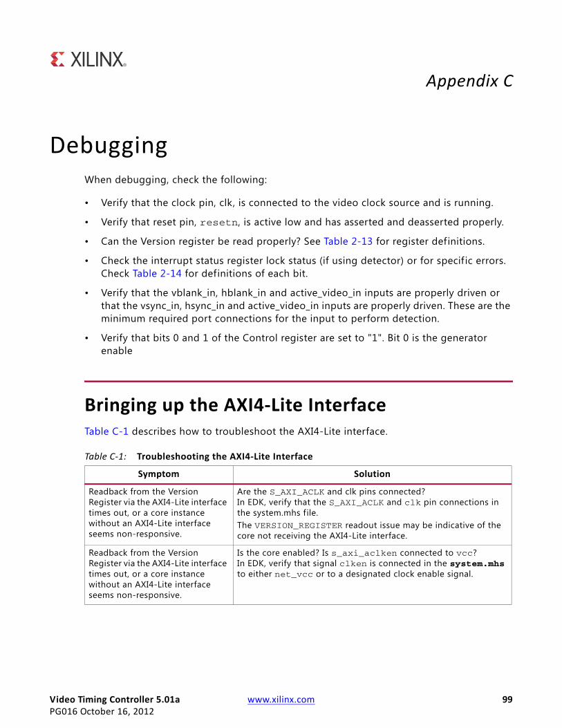
Video Timing Controller 5.01a www.xilinx.com 99PG016 October 16, 2012
Appendix C
DebuggingWhen debugging, check the following:
• Verify that the clock pin, clk, is connected to the video clock source and is running.
• Verify that reset pin, resetn, is active low and has asserted and deasserted properly.
• Can the Version register be read properly? See Table 2-13 for register definitions.
• Check the interrupt status register lock status (if using detector) or for specif ic errors. Check Table 2-14 for definitions of each bit.
• Verify that the vblank_in, hblank_in and active_video_in inputs are properly driven or that the vsync_in, hsync_in and active_video_in inputs are properly driven. These are the minimum required port connections for the input to perform detection.
• Verify that bits 0 and 1 of the Control register are set to "1". Bit 0 is the generator enable
Bringing up the AXI4-Lite InterfaceTable C-1 describes how to troubleshoot the AXI4-Lite interface.
Table C-1: Troubleshooting the AXI4-Lite Interface
Symptom Solution
Readback from the Version Register via the AXI4-Lite interface times out, or a core instance without an AXI4-Lite interface seems non-responsive.
Are the S_AXI_ACLK and clk pins connected?In EDK, verify that the S_AXI_ACLK and clk pin connections in the system.mhs file. The VERSION_REGISTER readout issue may be indicative of the core not receiving the AXI4-Lite interface.
Readback from the Version Register via the AXI4-Lite interface times out, or a core instance without an AXI4-Lite interface seems non-responsive.
Is the core enabled? Is s_axi_aclken connected to vcc? In EDK, verify that signal clken is connected in the system.mhs to either net_vcc or to a designated clock enable signal.
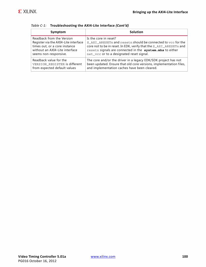
Video Timing Controller 5.01a www.xilinx.com 100PG016 October 16, 2012
Bringing up the AXI4-Lite Interface
Readback from the Version Register via the AXI4-Lite interface times out, or a core instance without an AXI4-Lite interface seems non-responsive.
Is the core in reset? S_AXI_ARESETn and resetn should be connected to vcc for the core not to be in reset. In EDK, verify that the S_AXI_ARESETn and resetn signals are connected in the system.mhs to either net_vcc or to a designated reset signal.
Readback value for the VERSION_REGISTER is different from expected default values
The core and/or the driver in a legacy EDK/SDK project has not been updated. Ensure that old core versions, implementation files, and implementation caches have been cleared.
Table C-1: Troubleshooting the AXI4-Lite Interface (Cont’d)
Symptom Solution
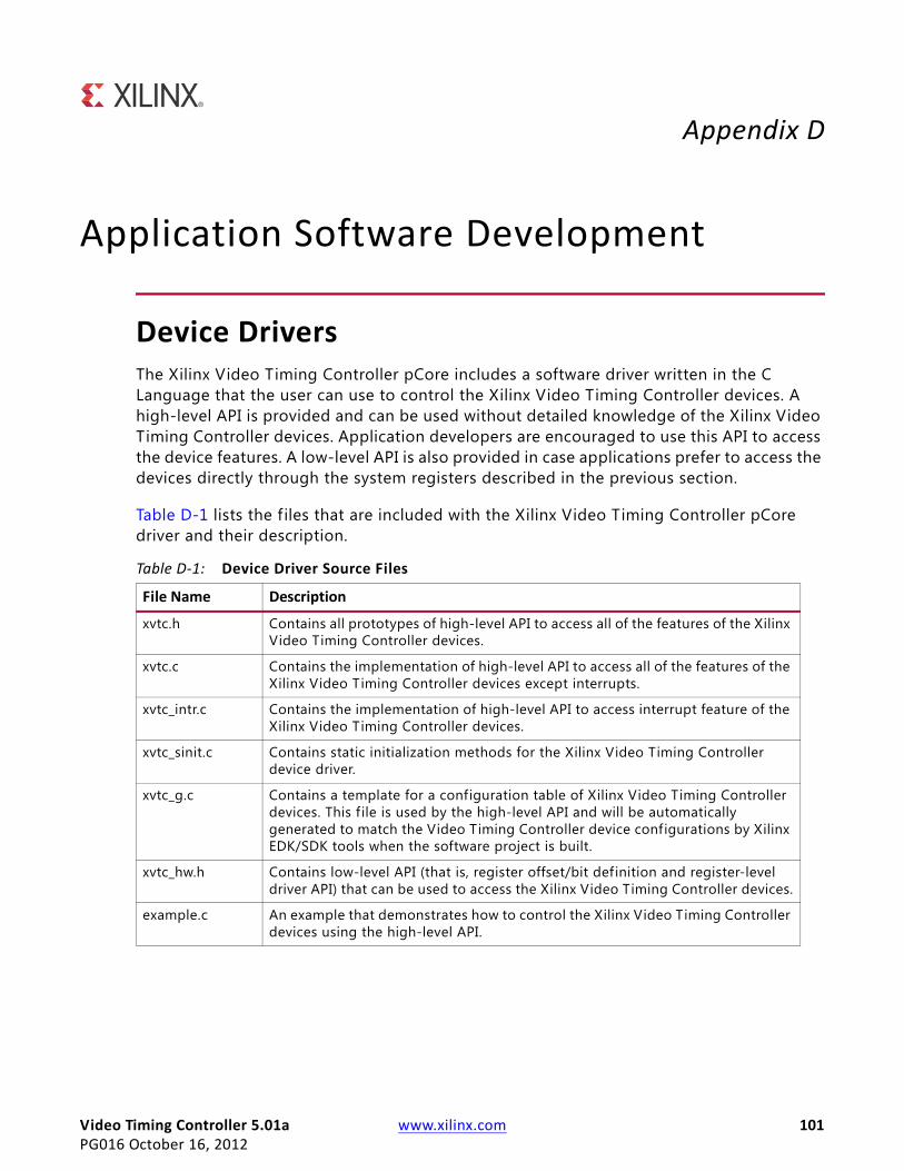
Video Timing Controller 5.01a www.xilinx.com 101PG016 October 16, 2012
Appendix D
Application Software Development
Device DriversThe Xilinx Video Timing Controller pCore includes a software driver written in the C Language that the user can use to control the Xilinx Video Timing Controller devices. A high-level API is provided and can be used without detailed knowledge of the Xilinx Video Timing Controller devices. Application developers are encouraged to use this API to access the device features. A low-level API is also provided in case applications prefer to access the devices directly through the system registers described in the previous section.
Table D-1 lists the f iles that are included with the Xilinx Video Timing Controller pCore driver and their description.
Table D-1: Device Driver Source Files
File Name Description
xvtc.h Contains all prototypes of high-level API to access all of the features of the Xilinx Video Timing Controller devices.
xvtc.c Contains the implementation of high-level API to access all of the features of the Xilinx Video Timing Controller devices except interrupts.
xvtc_intr.c Contains the implementation of high-level API to access interrupt feature of the Xilinx Video Timing Controller devices.
xvtc_sinit.c Contains static initialization methods for the Xilinx Video Timing Controller device driver.
xvtc_g.c Contains a template for a configuration table of Xilinx Video Timing Controller devices. This f ile is used by the high-level API and will be automatically generated to match the Video Timing Controller device configurations by Xilinx EDK/SDK tools when the software project is built.
xvtc_hw.h Contains low-level API (that is, register offset/bit definition and register-level driver API) that can be used to access the Xilinx Video Timing Controller devices.
example.c An example that demonstrates how to control the Xilinx Video Timing Controller devices using the high-level API.
Video Timing Controller 5.01a www.xilinx.com 102PG016 October 16, 2012
pCore API Functions
pCore API FunctionsThis section describes the functions included in the pcore Driver f iles generated for the Video Timing Controller pCore. The software API is provide to allow easy access to the registers of the pCore as defined in Table 2-12 in the Register Space section. To utilize the API functions provided, the following header f iles must be included in the user's C code:
• #include "xparameters.h"
• #include "xvtc.h"
The hardware settings of your system, including the base address of your Video Timing Controller core are defined in the xparameters.h f ile. The xvtc.h file provides the API access to all of the features of the Object Segmentation device driver. More detailed documentation of the API functions can be found by opening the f ile index.html in the pCore directory vtc_v5_01_a/doc/html/api.
Functions in xvtc.c• int XVtc_CfgInitialize (XVtc *InstancePtr, XVtc_Config *CfgPtr, u32 EffectiveAddr)
This function initializes a VTC device.
• void XVtc_Enable (XVtc *InstancePtr, u32 Type)
This function enables a VTC device.
• void XVtc_Disable (XVtc *InstancePtr, u32 Type)
This function disables a VTC device.
• void XVtc_SetPolarity (XVtc *InstancePtr, XVtc_Polarity *PolarityPtr)
This function sets up the output polarity of a VTC device.
• void XVtc_GetPolarity (XVtc *InstancePtr, XVtc_Polarity *PolarityPtr)
This function gets the output polarity setting used by a VTC device.
• void XVtc_SetSource (XVtc *InstancePtr, XVtc_SourceSelect *SourcePtr)
This function sets up the source selecting of a VTC device.
• void XVtc_GetSource (XVtc *InstancePtr, XVtc_SourceSelect *SourcePtr)
This function gets the source select setting used by a VTC device.
• void XVtc_SetSkipLine (XVtc *InstancePtr, int GeneratorChromaSkip)
Video Timing Controller 5.01a www.xilinx.com 103PG016 October 16, 2012
pCore API Functions
This function sets up the line skip setting of the Generator in a VTC device.
• void XVtc_GetSkipLine (XVtc *InstancePtr, int *GeneratorChromaSkipPtr)
This function gets the line skip setting used by the Generator in a VTC device.
• void XVtc_SetSkipPixel (XVtc *InstancePtr, int GeneratorChromaSkip)
This function sets up the pixel skip setting of the Generator in a VTC device.
• void XVtc_GetSkipPixel (XVtc *InstancePtr, int *GeneratorChromaSkipPtr)
This function gets the pixel skip setting used by the Generator in a VTC device.
• void XVtc_SetDelay (XVtc *InstancePtr, int VertDelay, int HoriDelay)
This function sets up the Generator delay setting of a VTC device.
• void XVtc_GetDelay (XVtc *InstancePtr, int *VertDelayPtr, int *HoriDelayPtr)
This function gets the Generator delay setting used by a VTC device.
• void XVtc_SetFSync (XVtc *InstancePtr, u16 FrameSyncIndex, u16 VertStart, u16 HoriStart)
This function sets up the SYNC setting of a Frame Sync used by VTC device.
• void XVtc_GetFSync (XVtc *InstancePtr, u16 FrameSyncIndex, u16 *VertStartPtr, u16 *HoriStartPtr)
This function gets the SYNC setting of a Frame Sync used by VTC device.
• void XVtc_SetGeneratorHoriOffset (XVtc *InstancePtr, XVtc_HoriOffsets *HoriOffsets)
This function sets the VBlank/VSync Horizontal Offsets for the Generator in a VTC device.
• void XVtc_GetGeneratorHoriOffset (XVtc *InstancePtr, XVtc_HoriOffsets *HoriOffsets)
This function gets the VBlank/VSync Horizontal Offsets currently used by the Generator in a VTC device.
• void XVtc_GetDetectorHoriOffset (XVtc *InstancePtr, XVtc_HoriOffsets *HoriOffsets)
This function gets the VBlank/VSync Horizontal Offsets detected by the Detector in a VTC device.
• void XVtc_SetGenerator (XVtc *InstancePtr, XVtc_Signal *SignalCfgPtr)
This function sets up VTC signal to be used by the Generator module in a VTC device.
• void XVtc_GetGenerator (XVtc *InstancePtr, XVtc_Signal *SignalCfgPtr)
Video Timing Controller 5.01a www.xilinx.com 104PG016 October 16, 2012
pCore API Functions
This function gets the VTC signal setting used by the Generator module in a VTC device.
• void XVtc_GetDetector (XVtc *InstancePtr, XVtc_Signal *SignalCfgPtr)
This function gets the VTC signal setting used by the Detector module in a VTC device.
• void XVtc_GetVersion (XVtc *InstancePtr, u16 *Major, u16 *Minor, u16 *Revision)
This function returns the version of a VTC device.
Functions in xvtc_sinit.c• XVtc_Config * XVtc_LookupConfig (u16 DeviceId)
XVtc_LookupConfig returns a reference to an XVtc_Config structure based on the unique device id, DeviceId.
Functions in xvtc_intr.c• void XVtc_IntrHandler (void *InstancePtr)
This function is the interrupt handler for the VTC driver.
• int XVtc_SetCallBack (XVtc *InstancePtr, u32 HandlerType, void *CallBackFunc, void *CallBackRef)
This routine installs an asynchronous callback function for the given HandlerType:.
Video Timing Controller 5.01a www.xilinx.com 105PG016 October 16, 2012
Appendix E
Additional Resources
Xilinx ResourcesFor support resources such as Answers, Documentation, Downloads, and Forums, see the Xilinx Support website at:
http://www.xilinx.com/support.
For a glossary of technical terms used in Xilinx documentation, see:
http://www.xilinx.com/support/documentation/sw_manuals/glossary.pdf.
For a comprehensive listing of Video and Imaging application notes, white papers, reference designs and related IP cores, see the Video and Imaging Resources page at:
http://www.xilinx.com/esp/video/refdes_listing.htm#ref_des.
Solution CentersSee the Xilinx Solution Centers for support on devices, software tools, and intellectual property at all stages of the design cycle. Topics include design assistance, advisories, and troubleshooting tips.
References These documents provide supplemental material useful with this user guide:
1. UG761 AXI Reference Guide.
2. Vivado Design Suite Migration Methodology Guide (UG911)
3. (Vivado™ Design Suite user documentation
Video Timing Controller 5.01a www.xilinx.com 106PG016 October 16, 2012
Technical Support
Technical SupportXilinx provides technical support at www.xilinx.com/support for this LogiCORE™ IP product when used as described in the product documentation. Xilinx cannot guarantee timing, functionality, or support of product if implemented in devices that are not defined in the documentation, if customized beyond that allowed in the product documentation, or if changes are made to any section of the design labeled DO NOT MODIFY.
See the IP Release Notes Guide (XTP025) for more information on this core. For each core, there is a master Answer Record that contains the Release Notes and Known Issues list for the core being used. The following information is listed for each version of the core:
• New Features
• Resolved Issues
• Known Issues
Revision HistoryThe following table shows the revision history for this document.
Notice of DisclaimerThe information disclosed to you hereunder (the “Materials”) is provided solely for the selection and use of Xilinx products. To the maximum extent permitted by applicable law: (1) Materials are made available “AS IS” and with all faults, Xilinx hereby DISCLAIMS ALL WARRANTIES AND CONDITIONS, EXPRESS, IMPLIED, OR STATUTORY, INCLUDING BUT NOT LIMITED TO WARRANTIES OF MERCHANTABILITY, NON-INFRINGEMENT, OR FITNESS FOR ANY PARTICULAR PURPOSE; and (2) Xilinx shall not be liable (whether in contract or tort, including negligence, or under any other theory of liability) for any loss or damage of any kind or nature related to, arising under, or in connection with, the Materials (including your use of the Materials), including for any direct, indirect, special, incidental, or consequential loss or damage (including loss of data, profits, goodwill, or any type of loss or damage suffered as a result of any action brought by a third party) even if such damage or loss was reasonably foreseeable or Xilinx had been advised of the possibility of the same. Xilinx assumes no obligation to correct any errors contained in the Materials or to notify you of updates to the Materials or to product specifications. You may not reproduce, modify, distribute, or publicly display the Materials without prior written consent. Certain products are subject to the terms and conditions of the Limited Warranties which can be viewed at http://www.xilinx.com/warranty.htm; IP cores may be subject to warranty and support terms contained in a license issued to you by Xilinx. Xilinx products are not designed or intended to be fail-safe or for use in any application requiring
Date Version Revision10/19/2011 1.0 Initial Xilinx release of Product Guide, replacing DS857.
4/24/2012 2.0 Updated for core version. Added Zynq-7000 devices, deprecated GPP interface.
07/25/2012 3.0 Updated for core version. Added Vivado information.
10/16/2012 3.1 Updated for core version and ISE v14.3 and Vivado v2012.3. Added Vivado test bench and constraints.
Video Timing Controller 5.01a www.xilinx.com 107PG016 October 16, 2012
Notice of Disclaimer
fail-safe performance; you assume sole risk and liability for use of Xilinx products in Critical Applications: http://www.xilinx.com/warranty.htm#critapps.© Copyright 2011-2012 Xilinx, Inc. Xilinx, the Xilinx logo, Artix, ISE, Kintex, Spartan, Virtex, Zynq, and other designated brands included herein are trademarks of Xilinx in the United States and other countries. All other trademarks are the property of their respective owners.


![SMPTE UHD-SDI Transmitter Subsystem v2 · LogiCORE IP Product Guide (PG205) [Ref6] for details. Video Timing Controller The Video Timing controller core is used to generate the Video](https://img.dokumen.tips/doc/110x75/5fa7bed6d8f11e3d9a71dab5/smpte-uhd-sdi-transmitter-subsystem-v2-logicore-ip-product-guide-pg205-ref6.jpg)