Embed Size (px)
Citation preview
LogiCORE IP AXI Performance Monitor v2.01aProduct Guide
PG037 October 16, 2012
AXI Performance Monitor v2.01a www.xilinx.com 2PG037 October 16, 2012
Table of ContentsIP Facts
Chapter 1: OverviewTarget Technology . . . . . . . . . . . . . . . . . . . . . . . . . . . . . . . . . . . . . . . . . . . . . . . . . . . . . . . . . . . . . . . . 11Applications . . . . . . . . . . . . . . . . . . . . . . . . . . . . . . . . . . . . . . . . . . . . . . . . . . . . . . . . . . . . . . . . . . . . . 11Unsupported Features. . . . . . . . . . . . . . . . . . . . . . . . . . . . . . . . . . . . . . . . . . . . . . . . . . . . . . . . . . . . . 12Licensing . . . . . . . . . . . . . . . . . . . . . . . . . . . . . . . . . . . . . . . . . . . . . . . . . . . . . . . . . . . . . . . . . . . . . . . . 12
Chapter 2: Product SpecificationPerformance. . . . . . . . . . . . . . . . . . . . . . . . . . . . . . . . . . . . . . . . . . . . . . . . . . . . . . . . . . . . . . . . . . . . . 14Resource Utilization. . . . . . . . . . . . . . . . . . . . . . . . . . . . . . . . . . . . . . . . . . . . . . . . . . . . . . . . . . . . . . . 14Signal Descriptions. . . . . . . . . . . . . . . . . . . . . . . . . . . . . . . . . . . . . . . . . . . . . . . . . . . . . . . . . . . . . . . . 15Design Parameters . . . . . . . . . . . . . . . . . . . . . . . . . . . . . . . . . . . . . . . . . . . . . . . . . . . . . . . . . . . . . . . . 37Register Space . . . . . . . . . . . . . . . . . . . . . . . . . . . . . . . . . . . . . . . . . . . . . . . . . . . . . . . . . . . . . . . . . . . 44
Chapter 3: Designing with the CoreGeneral Design Guidelines . . . . . . . . . . . . . . . . . . . . . . . . . . . . . . . . . . . . . . . . . . . . . . . . . . . . . . . . . 61Programming the Core. . . . . . . . . . . . . . . . . . . . . . . . . . . . . . . . . . . . . . . . . . . . . . . . . . . . . . . . . . . . . 62Clocking. . . . . . . . . . . . . . . . . . . . . . . . . . . . . . . . . . . . . . . . . . . . . . . . . . . . . . . . . . . . . . . . . . . . . . . . . 66Resets . . . . . . . . . . . . . . . . . . . . . . . . . . . . . . . . . . . . . . . . . . . . . . . . . . . . . . . . . . . . . . . . . . . . . . . . . . 66
Chapter 4: Customizing and Generating the CoreGUI . . . . . . . . . . . . . . . . . . . . . . . . . . . . . . . . . . . . . . . . . . . . . . . . . . . . . . . . . . . . . . . . . . . . . . . . . . . . 67
Chapter 5: Constraining the Core
Appendix 6: Migrating
Appendix A: Additional ResourcesXilinx Resources . . . . . . . . . . . . . . . . . . . . . . . . . . . . . . . . . . . . . . . . . . . . . . . . . . . . . . . . . . . . . . . . . . 72References . . . . . . . . . . . . . . . . . . . . . . . . . . . . . . . . . . . . . . . . . . . . . . . . . . . . . . . . . . . . . . . . . . . . . . 72Technical Support . . . . . . . . . . . . . . . . . . . . . . . . . . . . . . . . . . . . . . . . . . . . . . . . . . . . . . . . . . . . . . . . 72Revision History . . . . . . . . . . . . . . . . . . . . . . . . . . . . . . . . . . . . . . . . . . . . . . . . . . . . . . . . . . . . . . . . . . 73
AXI Performance Monitor v2.01a www.xilinx.com 3PG037 October 16, 2012
Notice of Disclaimer. . . . . . . . . . . . . . . . . . . . . . . . . . . . . . . . . . . . . . . . . . . . . . . . . . . . . . . . . . . . . . . 73
AXI Performance Monitor v2.01a www.xilinx.com 4PG037 October 16, 2012 Product Specification
IntroductionThe LogiCORE™ IP AXI Performance Monitor measures major performance metrics for the AMBA Advanced eXtensible Interface (AXI) system. The Performance Monitor measures bus latency of a specif ic master/slave (AXI4/AXI4-Stream) in a system, the amount of memory traffic for specif ic durations and other performance metrics.
Features• AXI4-Lite interface for register
configuration.
• Configurable number of monitor slots (max of 8). Each can be statically configured as AXI4 memory mapped (AXI4 MM) or AXI4-Stream.
• Flexible support for monitor slots with any data width, ID width and frequency.
• Optional FIFO at each monitor slot interface for clock domain crossing.
• Free running Global Clock Counter.
• Event Log module.
• Event Count module.
• External event can be counted with a maximum of 8. Each external event will have a corresponding Start and Stop signals. External events can also be clock domain crossed.
Additional features are listed in Chapter 1, Overview.
IP Facts
LogiCORE IP Facts Table
Core Specifics
Supported Device Family(1)
Zynq™-7000(2), Artix™-7,Kintex™-7, Virtex®-7,Virtex-6,
Spartan®-6
Supported User Interfaces AXI4-Stream, AXI4-Lite and AXI4
Resources See Table 2-1, Table 2-2, andTable 2-3.
Provided with Core
Design Files Verilog HDL, VHDL
Example Design Not Provided
Test Bench Not Provided
Constraints File XDC
Simulation Model None
Supported S/W Driver(3) Standalone
Tested Design Flows(4)
Design Entry Vivado™ Design Suite v2012.3(5)
Xilinx Platform Studio (XPS) 14.3
Simulation Mentor Graphics ModelSim
Synthesis XST v14.3Vivado Synthesis
SupportProvided by Xilinx @ www.xilinx.com/support
Notes: 1. For a complete list of supported derivative devices, see IDS
Embedded Edition Derivative Device Support.2. Supported in ISE Design Suite implementations only.3. Standalone driver details can be found in the EDK or SDK
directory (<install_directory>/doc/usenglish/xilinx_drivers.htm). Linux OS and driver support information is available from //wiki.xilinx.com.
4. For the supported versions of the tools, see the Xilinx Design Tools: Release Notes Guide.
5. Supports only 7 series devices.

AXI Performance Monitor v2.01a www.xilinx.com 5PG037 October 16, 2012
Chapter 1
OverviewThe LogiCORE™ IP AXI Performance Monitor measures major performance metrics for the AMBA Advanced eXtensible Interface (AXI) system. The Performance Monitor measures bus latency of a specif ic master/slave (AXI4/AXI4-Stream) in a system, the amount of memory traffic for specif ic durations, and other performance metrics.
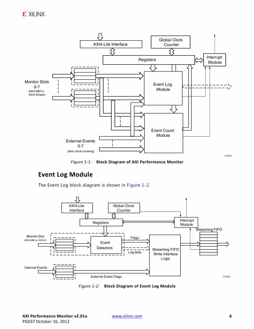
The Performance Monitor Unit (PMU) monitors and analyzes system behavior on an AXI bus of multi-core systems. It mainly consists of two modules:
• Event Log Module: Logs the interested events on the AXI monitor slots and external events coming in to a streaming FIFO, which can be read by the host and reconstruct the transactions for analyzing the system behavior/performance.
• Event Count Module: Provides monitoring hardware for counting events associated with AXI bus transactions and external events. The included hardware counters can be set, read by the software, and used to analyze and enhance the performance of the entire system.
All the AXI signals of agents in an AXI system are connected to the monitor slots of the core. Each slot can be configured as AXI4 MM or AXI4-Stream slots based on the agent connected.
Configuration registers are configured through the AXI4-Lite interface the core provides.
The top-level block diagram of the AXI Performance Monitor is shown in Figure 1-1.
AXI Performance Monitor v2.01a www.xilinx.com 6PG037 October 16, 2012
Event Log ModuleThe Event Log block diagram is shown in Figure 1-2.
X-Ref Target - Figure 1-1
Figure 1-1: Block Diagram of AXI Performance Monitor
X-Ref Target - Figure 1-2
Figure 1-2: Block Diagram of Event Log Module

AXI Performance Monitor v2.01a www.xilinx.com 7PG037 October 16, 2012
The Event Detector block generates the flags based on the events occurring at the Monitor Interface. The log generated for the AXI4 MM slot includes:
• Write Address Latch Flag
• First Write Flag
• Last Write Flag
• Response Flag
• Read Address Latch Flag
• First Read Flag
• Last Read Flag
• AWID
• BID
• ARID
• RID
• AWLEN
• ARLEN
The log generated for the AXI4-Stream slot includes:
• First Write Flag
• Last Write Flag
• TID
• TDEST
• TUSER
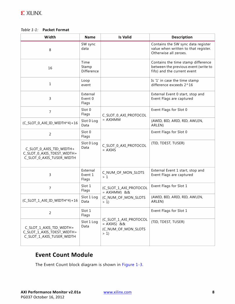
The packet format for the streaming FIFO is listed in Table 1-1. Table 1-1 shows the packet format for only two slots. The width of the packet increases with the number of slots in a similar fashion. The AXI4MM log data width is based on C_SHOW_AXI_IDS and C_SHOW_AXI_LEN. AXI4S log data width is based on C_SHOW_AXIS_TID, C_SHOW_AXIS_TDEST and C_SHOW_AXIS_TUSER.
AXI Performance Monitor v2.01a www.xilinx.com 8PG037 October 16, 2012
Event Count ModuleThe Event Count block diagram is shown in Figure 1-3.
Table 1-1: Packet Format
Width Name Is Valid Description
8 SW sync data
Contains the SW sync data register value when written to that register. Otherwise all zeroes.
16 Time Stamp Difference
Contains the time stamp difference between the previous event (write to f ifo) and the current event
1 Loop event
Is ‘1’ in case the time stamp difference exceeds 2^16
3External Event 0 Flags
External Event 0 start, stop and Event Flags are captured
7 Slot 0 Flags C_SLOT_0_AXI_PROTOCOL
= AXI4MM
Event Flags for Slot 0
(C_SLOT_0_AXI_ID_WIDTH*4)+16 Slot 0 Log Data
{AWID, BID, ARID, RID, AWLEN, ARLEN}
2 Slot 0 Flags
C_SLOT_0_AXI_PROTOCOL = AXI4S
Event Flags for Slot 0
C_SLOT_0_AXIS_TID_WIDTH+ C_SLOT_0_AXIS_TDEST_WIDTH+ C_SLOT_0_AXIS_TUSER_WIDTH
Slot 0 Log Data
{TID, TDEST, TUSER}
3External Event 1 Flags
C_NUM_OF_MON_SLOTS > 1
External Event 1 start, stop and Event Flags are captured
7 Slot 1 Flags
(C_SLOT_1_AXI_PROTOCOL= AXI4MM) && (C_NUM_OF_MON_SLOTS > 1)
Event Flags for Slot 1
(C_SLOT_1_AXI_ID_WIDTH*4)+16 Slot 1 Log Data
{AWID, BID, ARID, RID, AWLEN, ARLEN}
2 Slot 1 Flags
(C_SLOT_1_AXI_PROTOCOL = AXI4S) && (C_NUM_OF_MON_SLOTS > 1)
Event Flags for Slot 1
C_SLOT_1_AXIS_TID_WIDTH+ C_SLOT_1_AXIS_TDEST_WIDTH+ C_SLOT_1_AXIS_TUSER_WIDTH
Slot 1 Log Data
{TID, TDEST, TUSER}

AXI Performance Monitor v2.01a www.xilinx.com 9PG037 October 16, 2012
Event Count module consists of a configurable number of Accumulator and Range Incrementer blocks (max of 10). All the events that can be counted are detected and given to the accumulator which gives the aggregate value. The selection of event to monitor is done through the metric selector registers associated with the counters.
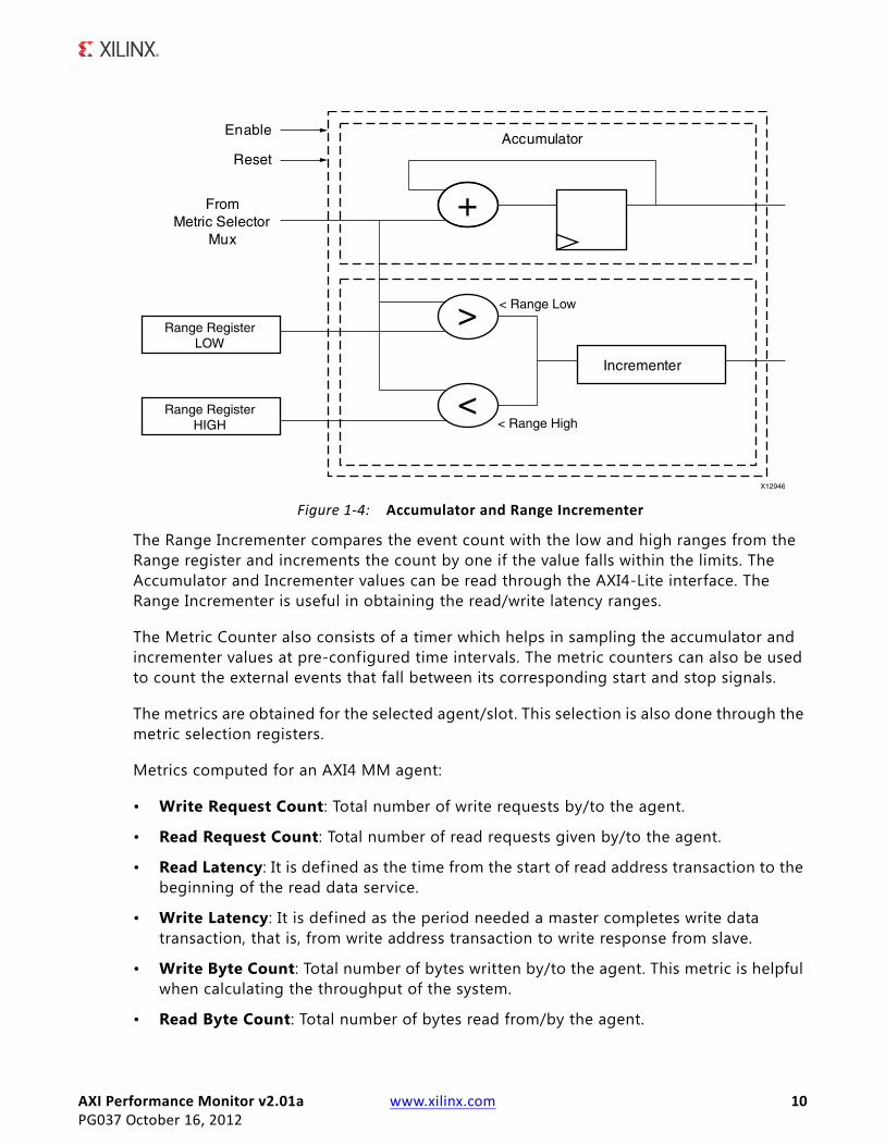
The Accumulator and Range Incrementer module is shown in Figure 1-4.
X-Ref Target - Figure 1-3
Figure 1-3: Event Count Module
AXI Performance Monitor v2.01a www.xilinx.com 10PG037 October 16, 2012
The Range Incrementer compares the event count with the low and high ranges from the Range register and increments the count by one if the value falls within the limits. The Accumulator and Incrementer values can be read through the AXI4-Lite interface. The Range Incrementer is useful in obtaining the read/write latency ranges.
The Metric Counter also consists of a timer which helps in sampling the accumulator and incrementer values at pre-configured time intervals. The metric counters can also be used to count the external events that fall between its corresponding start and stop signals.
The metrics are obtained for the selected agent/slot. This selection is also done through the metric selection registers.
Metrics computed for an AXI4 MM agent:
• Write Request Count: Total number of write requests by/to the agent.
• Read Request Count: Total number of read requests given by/to the agent.
• Read Latency: It is defined as the time from the start of read address transaction to the beginning of the read data service.
• Write Latency: It is defined as the period needed a master completes write data transaction, that is, from write address transaction to write response from slave.
• Write Byte Count: Total number of bytes written by/to the agent. This metric is helpful when calculating the throughput of the system.
• Read Byte Count: Total number of bytes read from/by the agent.
X-Ref Target - Figure 1-4
Figure 1-4: Accumulator and Range Incrementer
AXI Performance Monitor v2.01a www.xilinx.com 11PG037 October 16, 2012
Target Technology
• Average Write Latency: Average write latency seen by the agent. It can be derived from total write latency and the write request count.
• Average Read Latency: Average read latency seen by the agent. It can be derived from total read latency and the read request count.
• Slave Write Idle Cycle Count: Number of idle cycles caused by the slave during write transactions to the slave. The slave write idle cycles are the number of clocks between WVALID assertion and WREADY assertion.
• Master Read Idle Cycle Count: Number of idle cycles caused by the master during read transactions to the slave. The master read idle cycles are the number of clocks between RVALID assertion and RREADY assertion.
Metrics computed for an AXI4-Stream agent:
• Transfer Cycle Count: Total number of writes by/to the agent.
• Data Byte Count: Total number of data bytes written by/to the agent. This metric helps in calculating the throughput of the system.
• Position Byte Count: Total number of position bytes transferred.
• Null Byte Count: Total number of null bytes transferred.
• Packet Count: Total number of packets transferred.
• Slave Idle Count: Number of idle cycles caused by the slave.
• Master Idle Count: Number of idle cycles caused by the master.
System-level metrics like write data throughput, read data throughput, and interconnect read latency can be computed by obtaining all metrics for all the agents in the system.
Target TechnologyThis solution targets the Zynq-7000, Artix-7, Kintex-7, Virtex-7,Virtex-6, and Spartan-6 FPGA families.
ApplicationsThe AXI Performance Monitor has the following applications:
• Computing the cache hits/misses (hit ratio) and determining the optimal cache size for an application.
AXI Performance Monitor v2.01a www.xilinx.com 12PG037 October 16, 2012
Unsupported Features
• Studying the latencies involved for any AXI-based slave, like a memory controller, and tuning the core.
• Comparing different applications by facilitating benchmarking.
• Debugging a system, for example, counting the responses against requests.
• Obtaining charts like latency distribution, throughput, burst distribution and others for a slave and across the system.
• Obtaining the system-level metrics like write throughput, read throughput, average interconnect read latency and others.
• Obtaining the run time of an application and optimizing the software.
• Analyzing the latencies involved in transactions by identifying the agent causing more idle cycles in the transactions.
• Comparing two similar AXI agents.
• Counting the interested external events (other than AXI) like FIFO overflow/underflow, interrupts, and others.
• Logging the important or interested events on the monitor slots, reconstruct and analyze the behavior/performance.
Unsupported FeaturesThe AXI Performance Monitor has the following known limitations:
• Bus contention metrics are not computed.
• Due to logic constraints, the core does not provide all the metrics for all the agents in the system in a single run of the application.
• Only supports a reordering depth of 1. The read data reordering depth is the number of addresses pending in the slave that can be reordered.
• Does not support out-standing transactions.
• Does not support interleaved transactions.
LicensingThis Xilinx LogiCORE IP module is provided at no additional cost with the Xilinx Vivado Design Suite and ISE Design Suite Embedded Edition under the terms of the Xilinx End User License.
AXI Performance Monitor v2.01a www.xilinx.com 13PG037 October 16, 2012
Licensing
Information about this and other Xilinx LogiCORE IP modules is available at the Xilinx Intellectual Property page. For information on pricing and availability of other Xilinx LogiCORE IP modules and tools, contact your local Xilinx sales representative.
AXI Performance Monitor v2.01a www.xilinx.com 14PG037 October 16, 2012 Product Specification
Chapter 2
Product SpecificationThis chapter contains resource usage data, signal descriptions and details about the registers.
PerformanceThis section contains details about the performance of the core.
LatencyThe latency is the worst time the performance monitor requires for providing valid metric counters data through registers.
When the monitor clock and core clock are same, the latency is six clocks. When the monitor clock and core clock are asynchronous, Asynchronous FIFO latency is added to the standard latency, and so the effective latency is four monitor clocks and 13 core clocks.
Resource UtilizationBecause the AXI Performance Monitor is a module that will be used with other design pieces in the FPGA, the resource utilization and timing numbers reported in this section are estimates only. When the AXI Performance Monitor is combined with other pieces of the FPGA design, the utilization of FPGA resources and timing of the design will vary from the results reported here.
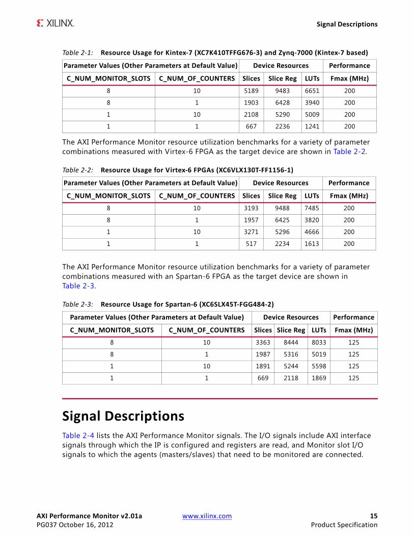
The AXI Performance Monitor resource utilization benchmarks for a variety of parameter combinations measured with the Vivado™ Design Suite using a Kintex ™-7 FPGA as the target device are shown in Table 2-1. Resource usage for Zynq ™-7000, Artix ™-7, and Virtex ®-7 devices can also be estimated based on Table 2-1.
AXI Performance Monitor v2.01a www.xilinx.com 15PG037 October 16, 2012 Product Specification
Signal Descriptions
The AXI Performance Monitor resource utilization benchmarks for a variety of parameter combinations measured with Virtex-6 FPGA as the target device are shown in Table 2-2.
The AXI Performance Monitor resource utilization benchmarks for a variety of parameter combinations measured with an Spartan-6 FPGA as the target device are shown in Table 2-3.
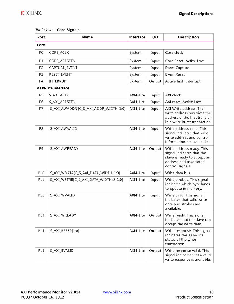
Signal DescriptionsTable 2-4 lists the AXI Performance Monitor signals. The I/O signals include AXI interface signals through which the IP is configured and registers are read, and Monitor slot I/O signals to which the agents (masters/slaves) that need to be monitored are connected.
Table 2-1: Resource Usage for Kintex-7 (XC7K410TFFG676-3) and Zynq-7000 (Kintex-7 based)
Parameter Values (Other Parameters at Default Value) Device Resources Performance
C_NUM_MONITOR_SLOTS C_NUM_OF_COUNTERS Slices Slice Reg LUTs Fmax (MHz)
8 10 5189 9483 6651 200
8 1 1903 6428 3940 200
1 10 2108 5290 5009 200
1 1 667 2236 1241 200
Table 2-2: Resource Usage for Virtex-6 FPGAs (XC6VLX130T-FF1156-1)
Parameter Values (Other Parameters at Default Value) Device Resources Performance
C_NUM_MONITOR_SLOTS C_NUM_OF_COUNTERS Slices Slice Reg LUTs Fmax (MHz)
8 10 3193 9488 7485 200
8 1 1957 6425 3820 200
1 10 3271 5296 4666 200
1 1 517 2234 1613 200
Table 2-3: Resource Usage for Spartan-6 (XC6SLX45T-FGG484-2)
Parameter Values (Other Parameters at Default Value) Device Resources Performance
C_NUM_MONITOR_SLOTS C_NUM_OF_COUNTERS Slices Slice Reg LUTs Fmax (MHz)
8 10 3363 8444 8033 125
8 1 1987 5316 5019 125
1 10 1891 5244 5598 125
1 1 669 2118 1869 125
AXI Performance Monitor v2.01a www.xilinx.com 16PG037 October 16, 2012 Product Specification
Signal Descriptions
Table 2-4: Core Signals
Port Name Interface I/O Description
Core
P0 CORE_ACLK System Input Core clock
P1 CORE_ARESETN System Input Core Reset. Active Low.
P2 CAPTURE_EVENT System Input Event Capture
P3 RESET_EVENT System Input Event Reset
P4 INTERRUPT System Output Active high Interrupt
AXI4-Lite Interface
P5 S_AXI_ACLK AXI4-Lite Input AXI clock.
P6 S_AXI_ARESETN AXI4-Lite Input AXI reset. Active Low.
P7 S_AXI_AWADDR [C_S_AXI_ADDR_WIDTH-1:0] AXI4-Lite Input AXI Write address. The write address bus gives the address of the first transfer in a write burst transaction.
P8 S_AXI_AWVALID AXI4-Lite Input Write address valid. This signal indicates that valid write address and control information are available.
P9 S_AXI_AWREADY AXI4-Lite Output Write address ready. This signal indicates that the slave is ready to accept an address and associated control signals.
P10 S_AXI_WDATA[C_S_AXI_DATA_WIDTH-1:0] AXI4-Lite Input Write data bus.
P11 S_AXI_WSTRB[C_S_AXI_DATA_WIDTH/8-1:0] AXI4-Lite Input Write strobes. This signal indicates which byte lanes to update in memory.
P12 S_AXI_WVALID AXI4-Lite Input Write valid. This signal indicates that valid write data and strobes are available.
P13 S_AXI_WREADY AXI4-Lite Output Write ready. This signal indicates that the slave can accept the write data.
P14 S_AXI_BRESP[1:0] AXI4-Lite Output Write response. This signal indicates the AXI4-Lite status of the write transaction.
P15 S_AXI_BVALID AXI4-Lite Output Write response valid. This signal indicates that a valid write response is available.

AXI Performance Monitor v2.01a www.xilinx.com 17PG037 October 16, 2012 Product Specification
Signal Descriptions
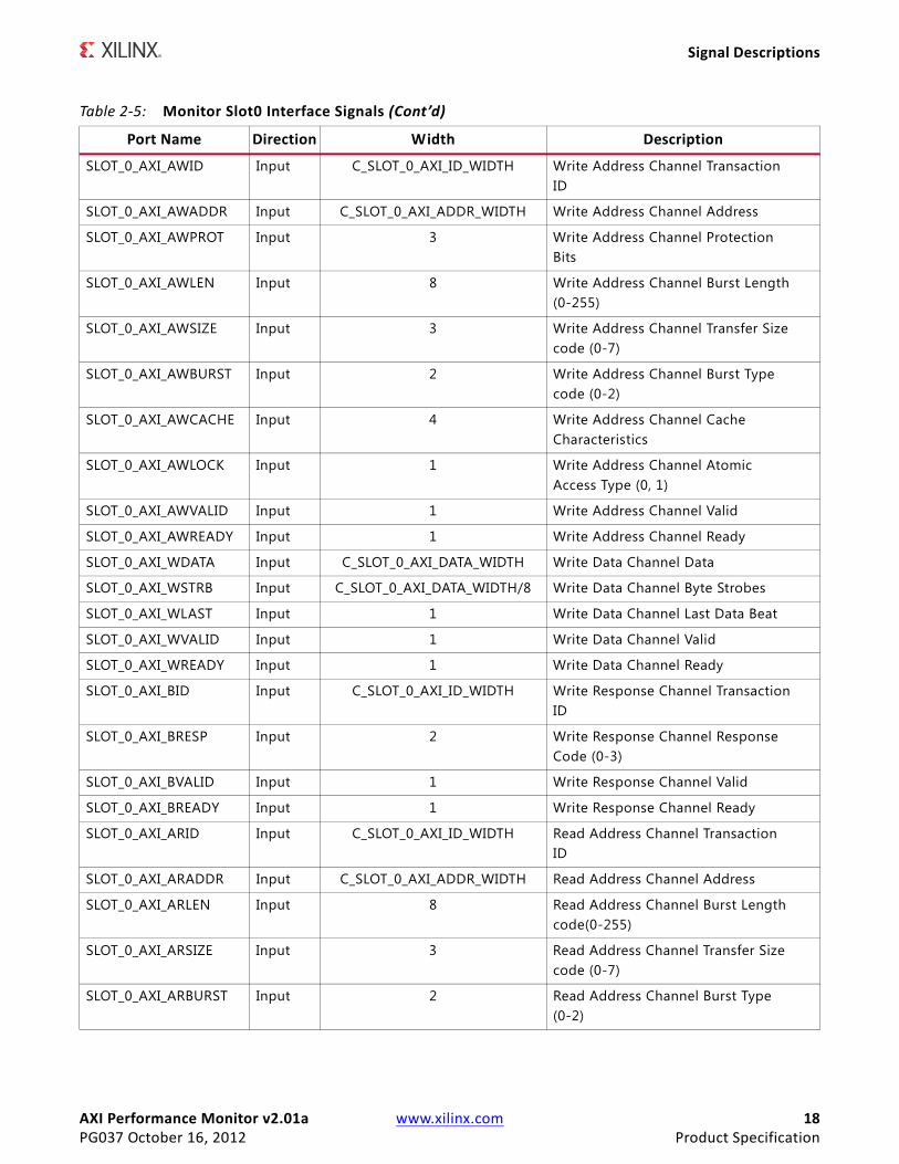
Monitor Slot0 InterfaceTable 2-5 lists the Monitor Slot 0 interface signals. Monitor Slot0 AXI MM/AXI Stream ports are enabled based on SLOT 0 protocol parameter, C_SLOT_0_AXI_PROTOCOL.
P16 S_AXI_BREADY AXI4-Lite Input Response ready. This signal indicates that the master can accept the response information.
P17 S_AXI_ARADDR[C_S_AXI_ADDR_WIDTH-1:0] AXI4-Lite Input Read address. The read address bus gives the initial address of a read burst transaction.
P18 S_AXI_ARVALID AXI4-Lite Input Read address valid. This signal indicates, when HIGH, that the read address and control information is valid and will remain stable until the address acknowledgement signal, S_AXI_ARREADY is High.
P19 S_AXI_ARREADY AXI4-Lite Output Read address ready. This signal indicates that the slave is ready to accept an address and associated control signals.
P20 S_AXI_RDATA[C_S_AXI_DATA_WIDTH-1:0] AXI4-Lite Output Read data bus.
P21 S_AXI_RRESP[1:0] AXI4-Lite Output Read response. This signal indicates the status of the read transfer.
P22 S_AXI_RVALID AXI4-Lite Output Read valid. This signal indicates that the required read data is available and the read transfer can complete.
P23 S_AXI_RREADY AXI4-Lite Input Read ready. This signal indicates that the master can accept the read data and response information.
Table 2-4: Core Signals (Cont’d)
Port Name Interface I/O Description
Table 2-5: Monitor Slot0 Interface Signals
Port Name Direction Width Description
Monitor Slot0 AXI MM
SLOT_0_AXI_ACLK Input 1 AXI Clock
SLOT_0_AXI_ARESETN Input 1 AXI Active Low Reset
AXI Performance Monitor v2.01a www.xilinx.com 18PG037 October 16, 2012 Product Specification
Signal Descriptions
SLOT_0_AXI_AWID Input C_SLOT_0_AXI_ID_WIDTH Write Address Channel TransactionID
SLOT_0_AXI_AWADDR Input C_SLOT_0_AXI_ADDR_WIDTH Write Address Channel Address
SLOT_0_AXI_AWPROT Input 3 Write Address Channel ProtectionBits
SLOT_0_AXI_AWLEN Input 8 Write Address Channel Burst Length(0-255)
SLOT_0_AXI_AWSIZE Input 3 Write Address Channel Transfer Sizecode (0-7)
SLOT_0_AXI_AWBURST Input 2 Write Address Channel Burst Typecode (0-2)
SLOT_0_AXI_AWCACHE Input 4 Write Address Channel CacheCharacteristics
SLOT_0_AXI_AWLOCK Input 1 Write Address Channel AtomicAccess Type (0, 1)
SLOT_0_AXI_AWVALID Input 1 Write Address Channel Valid
SLOT_0_AXI_AWREADY Input 1 Write Address Channel Ready
SLOT_0_AXI_WDATA Input C_SLOT_0_AXI_DATA_WIDTH Write Data Channel Data
SLOT_0_AXI_WSTRB Input C_SLOT_0_AXI_DATA_WIDTH/8 Write Data Channel Byte Strobes
SLOT_0_AXI_WLAST Input 1 Write Data Channel Last Data Beat
SLOT_0_AXI_WVALID Input 1 Write Data Channel Valid
SLOT_0_AXI_WREADY Input 1 Write Data Channel Ready
SLOT_0_AXI_BID Input C_SLOT_0_AXI_ID_WIDTH Write Response Channel TransactionID
SLOT_0_AXI_BRESP Input 2 Write Response Channel ResponseCode (0-3)
SLOT_0_AXI_BVALID Input 1 Write Response Channel Valid
SLOT_0_AXI_BREADY Input 1 Write Response Channel Ready
SLOT_0_AXI_ARID Input C_SLOT_0_AXI_ID_WIDTH Read Address Channel TransactionID
SLOT_0_AXI_ARADDR Input C_SLOT_0_AXI_ADDR_WIDTH Read Address Channel Address
SLOT_0_AXI_ARLEN Input 8 Read Address Channel Burst Lengthcode(0-255)
SLOT_0_AXI_ARSIZE Input 3 Read Address Channel Transfer Sizecode (0-7)
SLOT_0_AXI_ARBURST Input 2 Read Address Channel Burst Type(0-2)
Table 2-5: Monitor Slot0 Interface Signals (Cont’d)
Port Name Direction Width Description
AXI Performance Monitor v2.01a www.xilinx.com 19PG037 October 16, 2012 Product Specification
Signal Descriptions
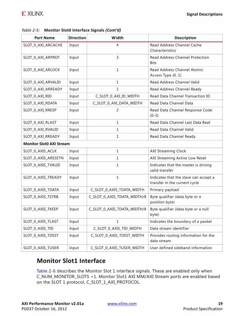
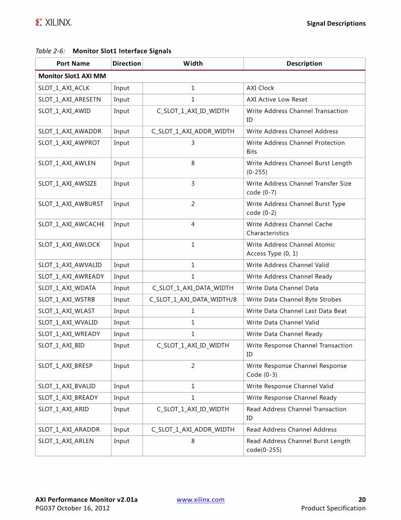
Monitor Slot1 InterfaceTable 2-6 describes the Monitor Slot 1 interface signals. These are enabled only when C_NUM_MONITOR_SLOTS >1. Monitor Slot1 AXI MM/AXI Stream ports are enabled based on the SLOT 1 protocol, C_SLOT_1_AXI_PROTOCOL.
SLOT_0_AXI_ARCACHE Input 4 Read Address Channel CacheCharacteristics
SLOT_0_AXI_ARPROT Input 3 Read Address Channel ProtectionBits
SLOT_0_AXI_ARLOCK Input 1 Read Address Channel AtomicAccess Type (0, 1)
SLOT_0_AXI_ARVALID Input 1 Read Address Channel Valid
SLOT_0_AXI_ARREADY Input 1 Read Address Channel Ready
SLOT_0_AXI_RID Input C_SLOT_0_AXI_ID_WIDTH Read Data Channel Transaction ID
SLOT_0_AXI_RDATA Input C_SLOT_0_AXI_DATA_WIDTH Read Data Channel Data
SLOT_0_AXI_RRESP Input 2 Read Data Channel Response Code(0-3)
SLOT_0_AXI_RLAST Input 1 Read Data Channel Last Data Beat
SLOT_0_AXI_RVALID Input 1 Read Data Channel Valid
SLOT_0_AXI_RREADY Input 1 Read Data Channel Ready
Monitor Slot0 AXI Stream
SLOT_0_AXIS_ACLK Input 1 AXI Streaming Clock
SLOT_0_AXIS_ARESETN Input 1 AXI Streaming Active Low Reset
SLOT_0_AXIS_TVALID Input 1 Indicates that the master is drivingvalid transfer
SLOT_0_AXIS_TREADY Input 1 Indicates that the slave can accept atransfer in the current cycle
SLOT_0_AXIS_TDATA Input C_SLOT_0_AXIS_TDATA_WIDTH Primary payload
SLOT_0_AXIS_TSTRB Input C_SLOT_0_AXIS_TDATA_WIDTH/8 Byte qualif ier (data byte or aposition byte)
SLOT_0_AXIS_TKEEP Input C_SLOT_0_AXIS_TDATA_WIDTH/8 Byte qualif ier (data byte or a nullbyte)
SLOT_0_AXIS_TLAST Input 1 Indicates the boundary of a packet
SLOT_0_AXIS_TID Input C_SLOT_0_AXIS_TID_WIDTH Data stream identif ier
SLOT_0_AXIS_TDEST Input C_SLOT_0_AXIS_TDEST_WIDTH Provides routing information for thedata stream
SLOT_0_AXIS_TUSER Input C_SLOT_0_AXIS_TUSER_WIDTH User defined sideband information
Table 2-5: Monitor Slot0 Interface Signals (Cont’d)
Port Name Direction Width Description
AXI Performance Monitor v2.01a www.xilinx.com 20PG037 October 16, 2012 Product Specification
Signal Descriptions
Table 2-6: Monitor Slot1 Interface Signals
Port Name Direction Width Description
Monitor Slot1 AXI MM
SLOT_1_AXI_ACLK Input 1 AXI Clock
SLOT_1_AXI_ARESETN Input 1 AXI Active Low Reset
SLOT_1_AXI_AWID Input C_SLOT_1_AXI_ID_WIDTH Write Address Channel TransactionID
SLOT_1_AXI_AWADDR Input C_SLOT_1_AXI_ADDR_WIDTH Write Address Channel Address
SLOT_1_AXI_AWPROT Input 3 Write Address Channel ProtectionBits
SLOT_1_AXI_AWLEN Input 8 Write Address Channel Burst Length(0-255)
SLOT_1_AXI_AWSIZE Input 3 Write Address Channel Transfer Sizecode (0-7)
SLOT_1_AXI_AWBURST Input 2 Write Address Channel Burst Typecode (0-2)
SLOT_1_AXI_AWCACHE Input 4 Write Address Channel CacheCharacteristics
SLOT_1_AXI_AWLOCK Input 1 Write Address Channel AtomicAccess Type (0, 1)
SLOT_1_AXI_AWVALID Input 1 Write Address Channel Valid
SLOT_1_AXI_AWREADY Input 1 Write Address Channel Ready
SLOT_1_AXI_WDATA Input C_SLOT_1_AXI_DATA_WIDTH Write Data Channel Data
SLOT_1_AXI_WSTRB Input C_SLOT_1_AXI_DATA_WIDTH/8 Write Data Channel Byte Strobes
SLOT_1_AXI_WLAST Input 1 Write Data Channel Last Data Beat
SLOT_1_AXI_WVALID Input 1 Write Data Channel Valid
SLOT_1_AXI_WREADY Input 1 Write Data Channel Ready
SLOT_1_AXI_BID Input C_SLOT_1_AXI_ID_WIDTH Write Response Channel TransactionID
SLOT_1_AXI_BRESP Input 2 Write Response Channel ResponseCode (0-3)
SLOT_1_AXI_BVALID Input 1 Write Response Channel Valid
SLOT_1_AXI_BREADY Input 1 Write Response Channel Ready
SLOT_1_AXI_ARID Input C_SLOT_1_AXI_ID_WIDTH Read Address Channel TransactionID
SLOT_1_AXI_ARADDR Input C_SLOT_1_AXI_ADDR_WIDTH Read Address Channel Address
SLOT_1_AXI_ARLEN Input 8 Read Address Channel Burst Lengthcode(0-255)

AXI Performance Monitor v2.01a www.xilinx.com 21PG037 October 16, 2012 Product Specification
Signal Descriptions
SLOT_1_AXI_ARSIZE Input 3 Read Address Channel Transfer Sizecode (0-7)
SLOT_1_AXI_ARBURST Input 2 Read Address Channel Burst Type(0-2)
SLOT_1_AXI_ARCACHE Input 4 Read Address Channel CacheCharacteristics
SLOT_1_AXI_ARPROT Input 3 Read Address Channel ProtectionBits
SLOT_1_AXI_ARLOCK Input 1 Read Address Channel AtomicAccess Type (0, 1)
SLOT_1_AXI_ARVALID Input 1 Read Address Channel Valid
SLOT_1_AXI_ARREADY Input 1 Read Address Channel Ready
SLOT_1_AXI_RID Input C_SLOT_1_AXI_ID_WIDTH Read Data Channel Transaction ID
SLOT_1_AXI_RDATA Input C_SLOT_1_AXI_DATA_WIDTH Read Data Channel Data
SLOT_1_AXI_RRESP Input 2 Read Data Channel Response Code(0-3)
SLOT_1_AXI_RLAST Input 1 Read Data Channel Last Data Beat
SLOT_1_AXI_RVALID Input 1 Read Data Channel Valid
SLOT_1_AXI_RREADY Input 1 Read Data Channel Ready
Monitor Slot1 AXI Stream
SLOT_1_AXIS_ACLK Input 1 AXI Streaming Clock
SLOT_1_AXIS_ARESETN Input 1 AXI Streaming Active Low Reset
SLOT_1_AXIS_TVALID Input 1 Indicates that the master is drivingvalid transfer
SLOT_1_AXIS_TREADY Input 1 Indicates that the slave can accept atransfer in the current cycle
SLOT_1_AXIS_TDATA Input C_SLOT_1_AXIS_TDATA_WIDTH Primary payload
SLOT_1_AXIS_TSTRB Input C_SLOT_1_AXIS_TDATA_WIDTH/8 Byte qualif ier (data byte or aposition byte)
SLOT_1_AXIS_TKEEP Input C_SLOT_1_AXIS_TDATA_WIDTH/8 Byte qualif ier (data byte or a nullbyte)
SLOT_1_AXIS_TLAST Input 1 Indicates the boundary of a packet
SLOT_1_AXIS_TID Input C_SLOT_1_AXIS_TID_WIDTH Data stream identif ier
SLOT_1_AXIS_TDEST Input C_SLOT_1_AXIS_TDEST_WIDTH Provides routing information for thedata stream
SLOT_1_AXIS_TUSER Input C_SLOT_1_AXIS_TUSER_WIDTH User defined sideband information
Table 2-6: Monitor Slot1 Interface Signals (Cont’d)
Port Name Direction Width Description
AXI Performance Monitor v2.01a www.xilinx.com 22PG037 October 16, 2012 Product Specification
Signal Descriptions
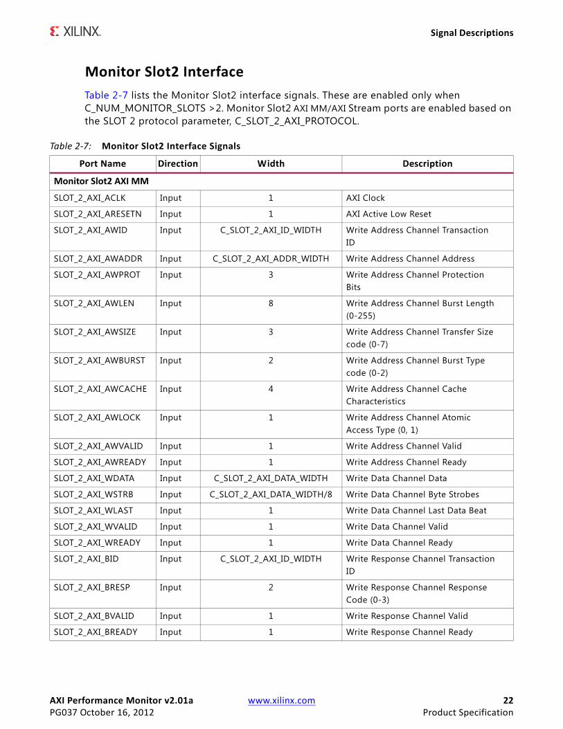
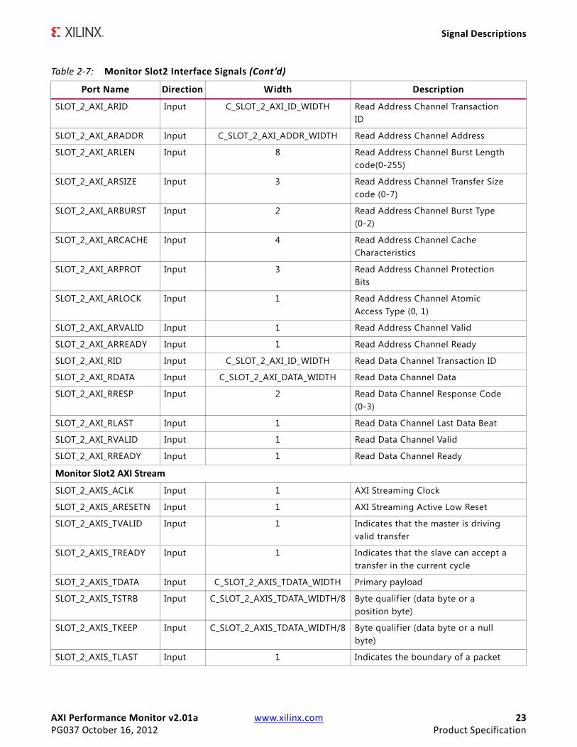
Monitor Slot2 InterfaceTable 2-7 lists the Monitor Slot2 interface signals. These are enabled only when C_NUM_MONITOR_SLOTS >2. Monitor Slot2 AXI MM/AXI Stream ports are enabled based on the SLOT 2 protocol parameter, C_SLOT_2_AXI_PROTOCOL.
Table 2-7: Monitor Slot2 Interface Signals
Port Name Direction Width Description
Monitor Slot2 AXI MM
SLOT_2_AXI_ACLK Input 1 AXI Clock
SLOT_2_AXI_ARESETN Input 1 AXI Active Low Reset
SLOT_2_AXI_AWID Input C_SLOT_2_AXI_ID_WIDTH Write Address Channel TransactionID
SLOT_2_AXI_AWADDR Input C_SLOT_2_AXI_ADDR_WIDTH Write Address Channel Address
SLOT_2_AXI_AWPROT Input 3 Write Address Channel ProtectionBits
SLOT_2_AXI_AWLEN Input 8 Write Address Channel Burst Length(0-255)
SLOT_2_AXI_AWSIZE Input 3 Write Address Channel Transfer Sizecode (0-7)
SLOT_2_AXI_AWBURST Input 2 Write Address Channel Burst Typecode (0-2)
SLOT_2_AXI_AWCACHE Input 4 Write Address Channel CacheCharacteristics
SLOT_2_AXI_AWLOCK Input 1 Write Address Channel AtomicAccess Type (0, 1)
SLOT_2_AXI_AWVALID Input 1 Write Address Channel Valid
SLOT_2_AXI_AWREADY Input 1 Write Address Channel Ready
SLOT_2_AXI_WDATA Input C_SLOT_2_AXI_DATA_WIDTH Write Data Channel Data
SLOT_2_AXI_WSTRB Input C_SLOT_2_AXI_DATA_WIDTH/8 Write Data Channel Byte Strobes
SLOT_2_AXI_WLAST Input 1 Write Data Channel Last Data Beat
SLOT_2_AXI_WVALID Input 1 Write Data Channel Valid
SLOT_2_AXI_WREADY Input 1 Write Data Channel Ready
SLOT_2_AXI_BID Input C_SLOT_2_AXI_ID_WIDTH Write Response Channel TransactionID
SLOT_2_AXI_BRESP Input 2 Write Response Channel ResponseCode (0-3)
SLOT_2_AXI_BVALID Input 1 Write Response Channel Valid
SLOT_2_AXI_BREADY Input 1 Write Response Channel Ready
AXI Performance Monitor v2.01a www.xilinx.com 23PG037 October 16, 2012 Product Specification
Signal Descriptions
SLOT_2_AXI_ARID Input C_SLOT_2_AXI_ID_WIDTH Read Address Channel TransactionID
SLOT_2_AXI_ARADDR Input C_SLOT_2_AXI_ADDR_WIDTH Read Address Channel Address
SLOT_2_AXI_ARLEN Input 8 Read Address Channel Burst Lengthcode(0-255)
SLOT_2_AXI_ARSIZE Input 3 Read Address Channel Transfer Sizecode (0-7)
SLOT_2_AXI_ARBURST Input 2 Read Address Channel Burst Type(0-2)
SLOT_2_AXI_ARCACHE Input 4 Read Address Channel CacheCharacteristics
SLOT_2_AXI_ARPROT Input 3 Read Address Channel ProtectionBits
SLOT_2_AXI_ARLOCK Input 1 Read Address Channel AtomicAccess Type (0, 1)
SLOT_2_AXI_ARVALID Input 1 Read Address Channel Valid
SLOT_2_AXI_ARREADY Input 1 Read Address Channel Ready
SLOT_2_AXI_RID Input C_SLOT_2_AXI_ID_WIDTH Read Data Channel Transaction ID
SLOT_2_AXI_RDATA Input C_SLOT_2_AXI_DATA_WIDTH Read Data Channel Data
SLOT_2_AXI_RRESP Input 2 Read Data Channel Response Code(0-3)
SLOT_2_AXI_RLAST Input 1 Read Data Channel Last Data Beat
SLOT_2_AXI_RVALID Input 1 Read Data Channel Valid
SLOT_2_AXI_RREADY Input 1 Read Data Channel Ready
Monitor Slot2 AXI Stream
SLOT_2_AXIS_ACLK Input 1 AXI Streaming Clock
SLOT_2_AXIS_ARESETN Input 1 AXI Streaming Active Low Reset
SLOT_2_AXIS_TVALID Input 1 Indicates that the master is drivingvalid transfer
SLOT_2_AXIS_TREADY Input 1 Indicates that the slave can accept atransfer in the current cycle
SLOT_2_AXIS_TDATA Input C_SLOT_2_AXIS_TDATA_WIDTH Primary payload
SLOT_2_AXIS_TSTRB Input C_SLOT_2_AXIS_TDATA_WIDTH/8 Byte qualif ier (data byte or aposition byte)
SLOT_2_AXIS_TKEEP Input C_SLOT_2_AXIS_TDATA_WIDTH/8 Byte qualif ier (data byte or a nullbyte)
SLOT_2_AXIS_TLAST Input 1 Indicates the boundary of a packet
Table 2-7: Monitor Slot2 Interface Signals (Cont’d)
Port Name Direction Width Description

AXI Performance Monitor v2.01a www.xilinx.com 24PG037 October 16, 2012 Product Specification
Signal Descriptions
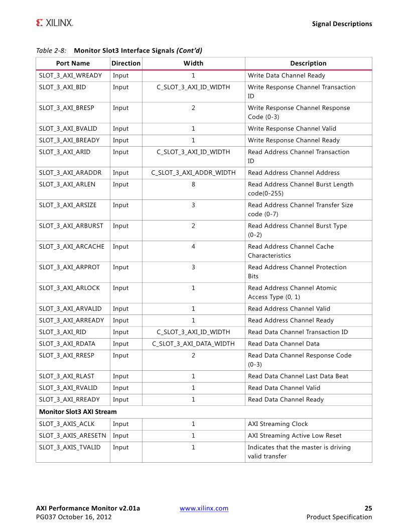
Monitor Slot3 InterfaceTable 2-8 lists the Monitor Slot3 interface signals. These are enabled only when C_NUM_MONITOR_SLOTS >3. Monitor Slot3 AXI MM/AXI Stream ports are enabled based on the SLOT 3 protocol parameter, C_SLOT_3_AXI_PROTOCOL.
SLOT_2_AXIS_TID Input C_SLOT_2_AXIS_TID_WIDTH Data stream identif ier
SLOT_2_AXIS_TDEST Input C_SLOT_2_AXIS_TDEST_WIDTH Provides routing information for thedata stream
SLOT_2_AXIS_TUSER Input C_SLOT_2_AXIS_TUSER_WIDTH User defined sideband information
Table 2-7: Monitor Slot2 Interface Signals (Cont’d)
Port Name Direction Width Description
Table 2-8: Monitor Slot3 Interface Signals
Port Name Direction Width Description
Monitor Slot3 AXI MM
SLOT_3_AXI_ACLK Input 1 AXI Clock
SLOT_3_AXI_ARESETN Input 1 AXI Active Low Reset
SLOT_3_AXI_AWID Input C_SLOT_3_AXI_ID_WIDTH Write Address Channel TransactionID
SLOT_3_AXI_AWADDR Input C_SLOT_3_AXI_ADDR_WIDTH Write Address Channel Address
SLOT_3_AXI_AWPROT Input 3 Write Address Channel ProtectionBits
SLOT_3_AXI_AWLEN Input 8 Write Address Channel Burst Length(0-255)
SLOT_3_AXI_AWSIZE Input 3 Write Address Channel Transfer Sizecode (0-7)
SLOT_3_AXI_AWBURST Input 2 Write Address Channel Burst Typecode (0-2)
SLOT_3_AXI_AWCACHE Input 4 Write Address Channel CacheCharacteristics
SLOT_3_AXI_AWLOCK Input 1 Write Address Channel AtomicAccess Type (0, 1)
SLOT_3_AXI_AWVALID Input 1 Write Address Channel Valid
SLOT_3_AXI_AWREADY Input 1 Write Address Channel Ready
SLOT_3_AXI_WID Input C_SLOT_3_AXI_ID_WIDTH
SLOT_3_AXI_WDATA Input C_SLOT_3_AXI_DATA_WIDTH Write Data Channel Data
SLOT_3_AXI_WSTRB Input C_SLOT_3_AXI_DATA_WIDTH/8 Write Data Channel Byte Strobes
SLOT_3_AXI_WLAST Input 1 Write Data Channel Last Data Beat
SLOT_3_AXI_WVALID Input 1 Write Data Channel Valid
AXI Performance Monitor v2.01a www.xilinx.com 25PG037 October 16, 2012 Product Specification
Signal Descriptions
SLOT_3_AXI_WREADY Input 1 Write Data Channel Ready
SLOT_3_AXI_BID Input C_SLOT_3_AXI_ID_WIDTH Write Response Channel TransactionID
SLOT_3_AXI_BRESP Input 2 Write Response Channel ResponseCode (0-3)
SLOT_3_AXI_BVALID Input 1 Write Response Channel Valid
SLOT_3_AXI_BREADY Input 1 Write Response Channel Ready
SLOT_3_AXI_ARID Input C_SLOT_3_AXI_ID_WIDTH Read Address Channel TransactionID
SLOT_3_AXI_ARADDR Input C_SLOT_3_AXI_ADDR_WIDTH Read Address Channel Address
SLOT_3_AXI_ARLEN Input 8 Read Address Channel Burst Lengthcode(0-255)
SLOT_3_AXI_ARSIZE Input 3 Read Address Channel Transfer Sizecode (0-7)
SLOT_3_AXI_ARBURST Input 2 Read Address Channel Burst Type(0-2)
SLOT_3_AXI_ARCACHE Input 4 Read Address Channel CacheCharacteristics
SLOT_3_AXI_ARPROT Input 3 Read Address Channel ProtectionBits
SLOT_3_AXI_ARLOCK Input 1 Read Address Channel AtomicAccess Type (0, 1)
SLOT_3_AXI_ARVALID Input 1 Read Address Channel Valid
SLOT_3_AXI_ARREADY Input 1 Read Address Channel Ready
SLOT_3_AXI_RID Input C_SLOT_3_AXI_ID_WIDTH Read Data Channel Transaction ID
SLOT_3_AXI_RDATA Input C_SLOT_3_AXI_DATA_WIDTH Read Data Channel Data
SLOT_3_AXI_RRESP Input 2 Read Data Channel Response Code(0-3)
SLOT_3_AXI_RLAST Input 1 Read Data Channel Last Data Beat
SLOT_3_AXI_RVALID Input 1 Read Data Channel Valid
SLOT_3_AXI_RREADY Input 1 Read Data Channel Ready
Monitor Slot3 AXI Stream
SLOT_3_AXIS_ACLK Input 1 AXI Streaming Clock
SLOT_3_AXIS_ARESETN Input 1 AXI Streaming Active Low Reset
SLOT_3_AXIS_TVALID Input 1 Indicates that the master is drivingvalid transfer
Table 2-8: Monitor Slot3 Interface Signals (Cont’d)
Port Name Direction Width Description
AXI Performance Monitor v2.01a www.xilinx.com 26PG037 October 16, 2012 Product Specification
Signal Descriptions
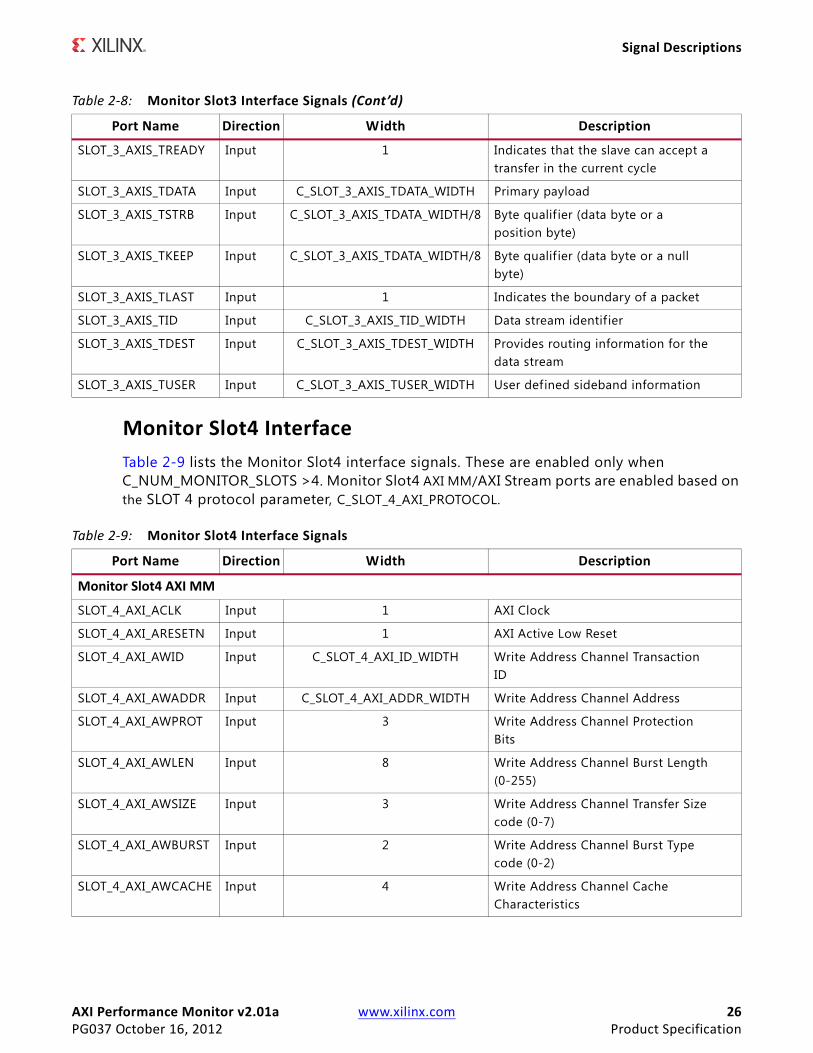
Monitor Slot4 InterfaceTable 2-9 lists the Monitor Slot4 interface signals. These are enabled only when C_NUM_MONITOR_SLOTS >4. Monitor Slot4 AXI MM/AXI Stream ports are enabled based on the SLOT 4 protocol parameter, C_SLOT_4_AXI_PROTOCOL.
SLOT_3_AXIS_TREADY Input 1 Indicates that the slave can accept atransfer in the current cycle
SLOT_3_AXIS_TDATA Input C_SLOT_3_AXIS_TDATA_WIDTH Primary payload
SLOT_3_AXIS_TSTRB Input C_SLOT_3_AXIS_TDATA_WIDTH/8 Byte qualif ier (data byte or aposition byte)
SLOT_3_AXIS_TKEEP Input C_SLOT_3_AXIS_TDATA_WIDTH/8 Byte qualif ier (data byte or a nullbyte)
SLOT_3_AXIS_TLAST Input 1 Indicates the boundary of a packet
SLOT_3_AXIS_TID Input C_SLOT_3_AXIS_TID_WIDTH Data stream identif ier
SLOT_3_AXIS_TDEST Input C_SLOT_3_AXIS_TDEST_WIDTH Provides routing information for thedata stream
SLOT_3_AXIS_TUSER Input C_SLOT_3_AXIS_TUSER_WIDTH User defined sideband information
Table 2-8: Monitor Slot3 Interface Signals (Cont’d)
Port Name Direction Width Description
Table 2-9: Monitor Slot4 Interface Signals
Port Name Direction Width Description
Monitor Slot4 AXI MM
SLOT_4_AXI_ACLK Input 1 AXI Clock
SLOT_4_AXI_ARESETN Input 1 AXI Active Low Reset
SLOT_4_AXI_AWID Input C_SLOT_4_AXI_ID_WIDTH Write Address Channel TransactionID
SLOT_4_AXI_AWADDR Input C_SLOT_4_AXI_ADDR_WIDTH Write Address Channel Address
SLOT_4_AXI_AWPROT Input 3 Write Address Channel ProtectionBits
SLOT_4_AXI_AWLEN Input 8 Write Address Channel Burst Length(0-255)
SLOT_4_AXI_AWSIZE Input 3 Write Address Channel Transfer Sizecode (0-7)
SLOT_4_AXI_AWBURST Input 2 Write Address Channel Burst Typecode (0-2)
SLOT_4_AXI_AWCACHE Input 4 Write Address Channel CacheCharacteristics

AXI Performance Monitor v2.01a www.xilinx.com 27PG037 October 16, 2012 Product Specification
Signal Descriptions
SLOT_4_AXI_AWLOCK Input 1 Write Address Channel AtomicAccess Type (0, 1)
SLOT_4_AXI_AWVALID Input 1 Write Address Channel Valid
SLOT_4_AXI_AWREADY Input 1 Write Address Channel Ready
SLOT_4_AXI_WID Input C_SLOT_4_AXI_ID_WIDTH
SLOT_4_AXI_WDATA Input C_SLOT_4_AXI_DATA_WIDTH Write Data Channel Data
SLOT_4_AXI_WSTRB Input C_SLOT_4_AXI_DATA_WIDTH/8 Write Data Channel Byte Strobes
SLOT_4_AXI_WLAST Input 1 Write Data Channel Last Data Beat
SLOT_4_AXI_WVALID Input 1 Write Data Channel Valid
SLOT_4_AXI_WREADY Input 1 Write Data Channel Ready
SLOT_4_AXI_BID Input C_SLOT_4_AXI_ID_WIDTH Write Response Channel TransactionID
SLOT_4_AXI_BRESP Input 2 Write Response Channel ResponseCode (0-3)
SLOT_4_AXI_BVALID Input 1 Write Response Channel Valid
SLOT_4_AXI_BREADY Input 1 Write Response Channel Ready
SLOT_4_AXI_ARID Input C_SLOT_4_AXI_ID_WIDTH Read Address Channel TransactionID
SLOT_4_AXI_ARADDR Input C_SLOT_4_AXI_ADDR_WIDTH Read Address Channel Address
SLOT_4_AXI_ARLEN Input 8 Read Address Channel Burst Lengthcode(0-255)
SLOT_4_AXI_ARSIZE Input 3 Read Address Channel Transfer Sizecode (0-7)
SLOT_4_AXI_ARBURST Input 2 Read Address Channel Burst Type(0-2)
SLOT_4_AXI_ARCACHE Input 4 Read Address Channel CacheCharacteristics
SLOT_4_AXI_ARPROT Input 3 Read Address Channel ProtectionBits
SLOT_4_AXI_ARLOCK Input 1 Read Address Channel AtomicAccess Type (0, 1)
SLOT_4_AXI_ARVALID Input 1 Read Address Channel Valid
SLOT_4_AXI_ARREADY Input 1 Read Address Channel Ready
SLOT_4_AXI_RID Input C_SLOT_4_AXI_ID_WIDTH Read Data Channel Transaction ID
SLOT_4_AXI_RDATA Input C_SLOT_4_AXI_DATA_WIDTH Read Data Channel Data
SLOT_4_AXI_RRESP Input 2 Read Data Channel Response Code(0-3)
Table 2-9: Monitor Slot4 Interface Signals (Cont’d)
Port Name Direction Width Description
AXI Performance Monitor v2.01a www.xilinx.com 28PG037 October 16, 2012 Product Specification
Signal Descriptions
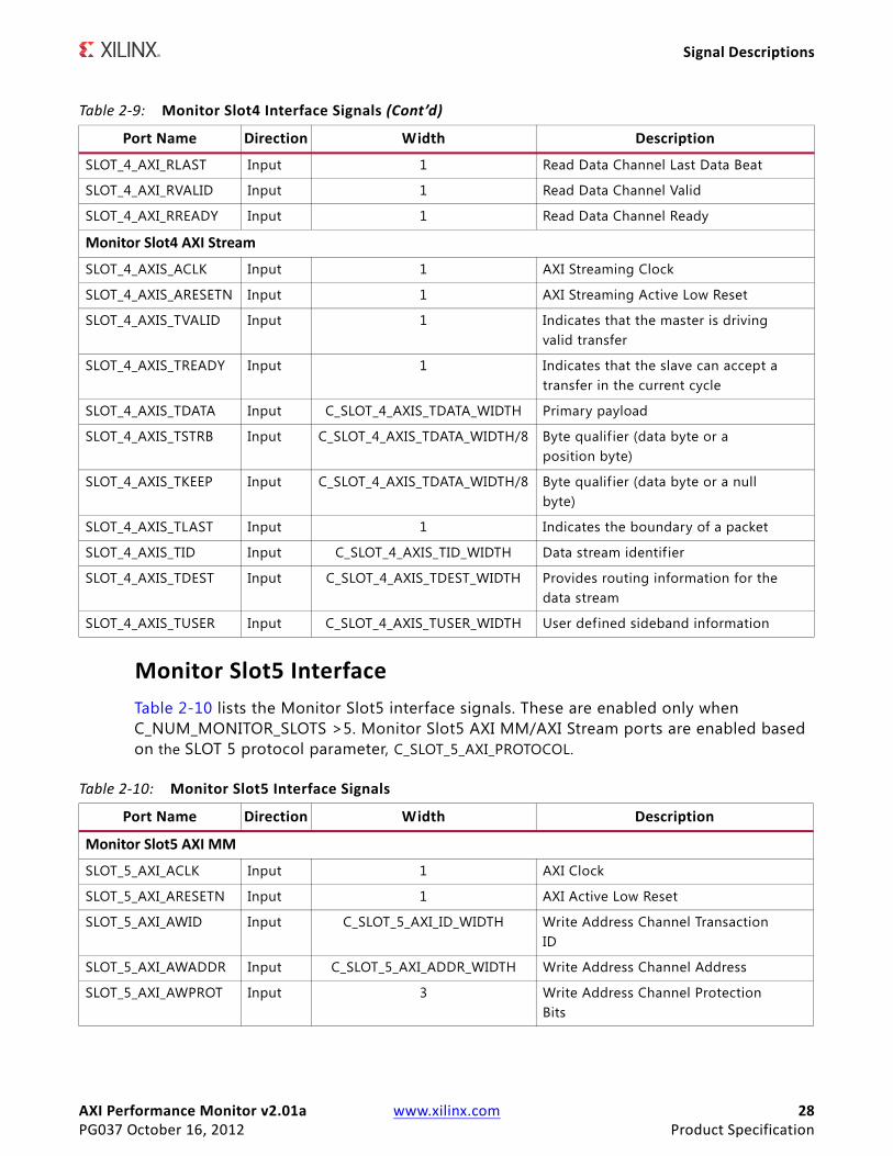
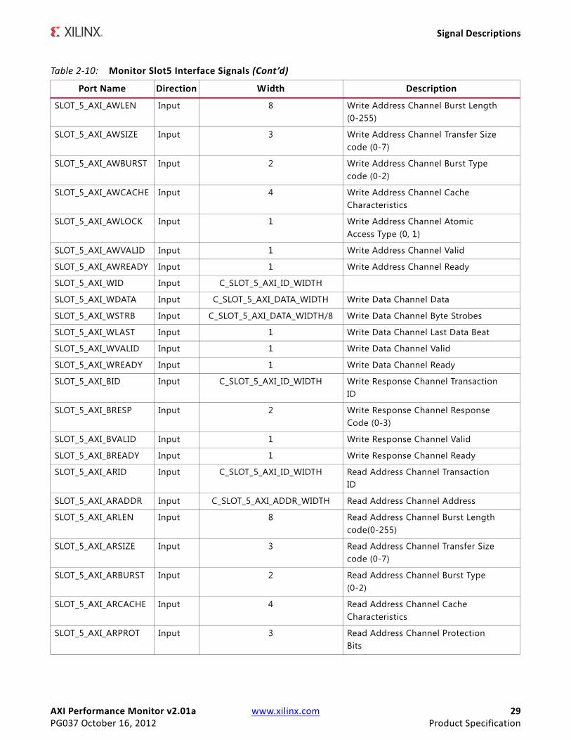
Monitor Slot5 InterfaceTable 2-10 lists the Monitor Slot5 interface signals. These are enabled only when C_NUM_MONITOR_SLOTS >5. Monitor Slot5 AXI MM/AXI Stream ports are enabled based on the SLOT 5 protocol parameter, C_SLOT_5_AXI_PROTOCOL.
SLOT_4_AXI_RLAST Input 1 Read Data Channel Last Data Beat
SLOT_4_AXI_RVALID Input 1 Read Data Channel Valid
SLOT_4_AXI_RREADY Input 1 Read Data Channel Ready
Monitor Slot4 AXI Stream
SLOT_4_AXIS_ACLK Input 1 AXI Streaming Clock
SLOT_4_AXIS_ARESETN Input 1 AXI Streaming Active Low Reset
SLOT_4_AXIS_TVALID Input 1 Indicates that the master is drivingvalid transfer
SLOT_4_AXIS_TREADY Input 1 Indicates that the slave can accept atransfer in the current cycle
SLOT_4_AXIS_TDATA Input C_SLOT_4_AXIS_TDATA_WIDTH Primary payload
SLOT_4_AXIS_TSTRB Input C_SLOT_4_AXIS_TDATA_WIDTH/8 Byte qualif ier (data byte or aposition byte)
SLOT_4_AXIS_TKEEP Input C_SLOT_4_AXIS_TDATA_WIDTH/8 Byte qualif ier (data byte or a nullbyte)
SLOT_4_AXIS_TLAST Input 1 Indicates the boundary of a packet
SLOT_4_AXIS_TID Input C_SLOT_4_AXIS_TID_WIDTH Data stream identif ier
SLOT_4_AXIS_TDEST Input C_SLOT_4_AXIS_TDEST_WIDTH Provides routing information for thedata stream
SLOT_4_AXIS_TUSER Input C_SLOT_4_AXIS_TUSER_WIDTH User defined sideband information
Table 2-9: Monitor Slot4 Interface Signals (Cont’d)
Port Name Direction Width Description
Table 2-10: Monitor Slot5 Interface Signals
Port Name Direction Width Description
Monitor Slot5 AXI MM
SLOT_5_AXI_ACLK Input 1 AXI Clock
SLOT_5_AXI_ARESETN Input 1 AXI Active Low Reset
SLOT_5_AXI_AWID Input C_SLOT_5_AXI_ID_WIDTH Write Address Channel TransactionID
SLOT_5_AXI_AWADDR Input C_SLOT_5_AXI_ADDR_WIDTH Write Address Channel Address
SLOT_5_AXI_AWPROT Input 3 Write Address Channel ProtectionBits
AXI Performance Monitor v2.01a www.xilinx.com 29PG037 October 16, 2012 Product Specification
Signal Descriptions
SLOT_5_AXI_AWLEN Input 8 Write Address Channel Burst Length(0-255)
SLOT_5_AXI_AWSIZE Input 3 Write Address Channel Transfer Sizecode (0-7)
SLOT_5_AXI_AWBURST Input 2 Write Address Channel Burst Typecode (0-2)
SLOT_5_AXI_AWCACHE Input 4 Write Address Channel CacheCharacteristics
SLOT_5_AXI_AWLOCK Input 1 Write Address Channel AtomicAccess Type (0, 1)
SLOT_5_AXI_AWVALID Input 1 Write Address Channel Valid
SLOT_5_AXI_AWREADY Input 1 Write Address Channel Ready
SLOT_5_AXI_WID Input C_SLOT_5_AXI_ID_WIDTH
SLOT_5_AXI_WDATA Input C_SLOT_5_AXI_DATA_WIDTH Write Data Channel Data
SLOT_5_AXI_WSTRB Input C_SLOT_5_AXI_DATA_WIDTH/8 Write Data Channel Byte Strobes
SLOT_5_AXI_WLAST Input 1 Write Data Channel Last Data Beat
SLOT_5_AXI_WVALID Input 1 Write Data Channel Valid
SLOT_5_AXI_WREADY Input 1 Write Data Channel Ready
SLOT_5_AXI_BID Input C_SLOT_5_AXI_ID_WIDTH Write Response Channel TransactionID
SLOT_5_AXI_BRESP Input 2 Write Response Channel ResponseCode (0-3)
SLOT_5_AXI_BVALID Input 1 Write Response Channel Valid
SLOT_5_AXI_BREADY Input 1 Write Response Channel Ready
SLOT_5_AXI_ARID Input C_SLOT_5_AXI_ID_WIDTH Read Address Channel TransactionID
SLOT_5_AXI_ARADDR Input C_SLOT_5_AXI_ADDR_WIDTH Read Address Channel Address
SLOT_5_AXI_ARLEN Input 8 Read Address Channel Burst Lengthcode(0-255)
SLOT_5_AXI_ARSIZE Input 3 Read Address Channel Transfer Sizecode (0-7)
SLOT_5_AXI_ARBURST Input 2 Read Address Channel Burst Type(0-2)
SLOT_5_AXI_ARCACHE Input 4 Read Address Channel CacheCharacteristics
SLOT_5_AXI_ARPROT Input 3 Read Address Channel ProtectionBits
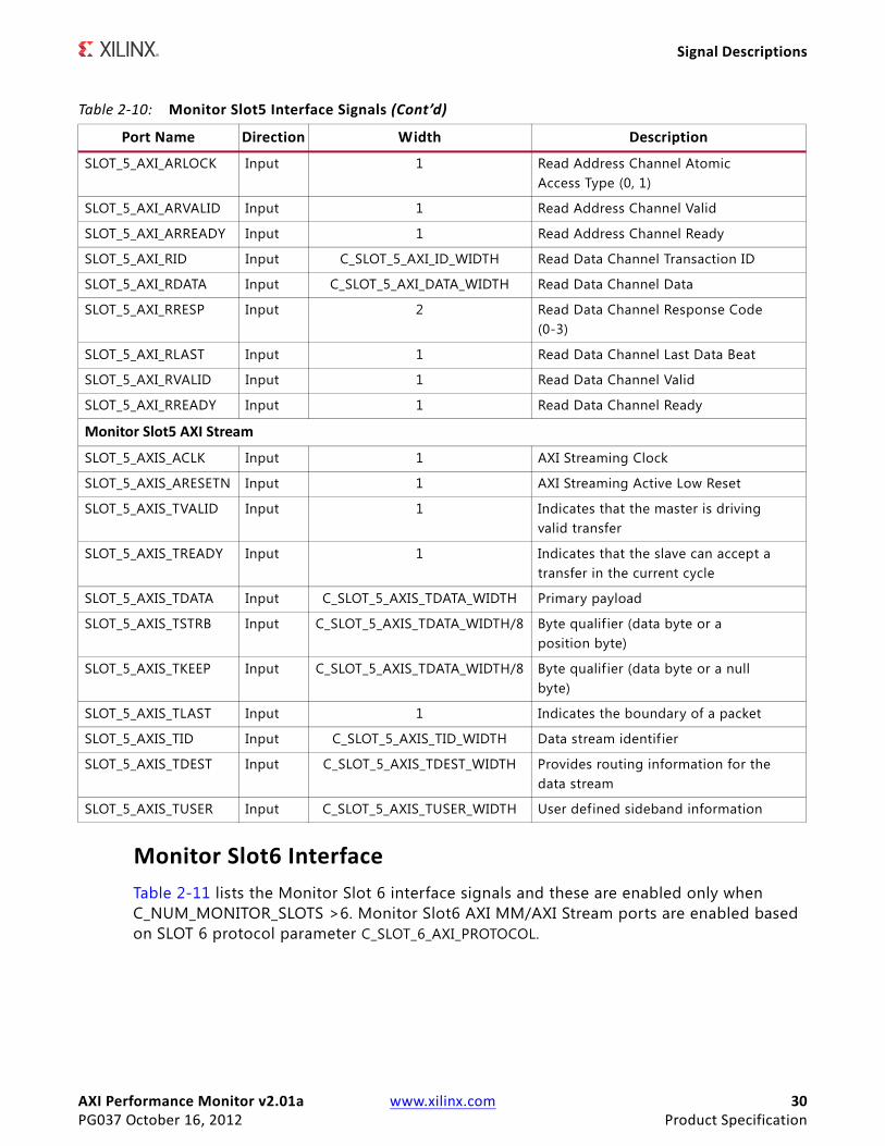
Table 2-10: Monitor Slot5 Interface Signals (Cont’d)
Port Name Direction Width Description
AXI Performance Monitor v2.01a www.xilinx.com 30PG037 October 16, 2012 Product Specification
Signal Descriptions
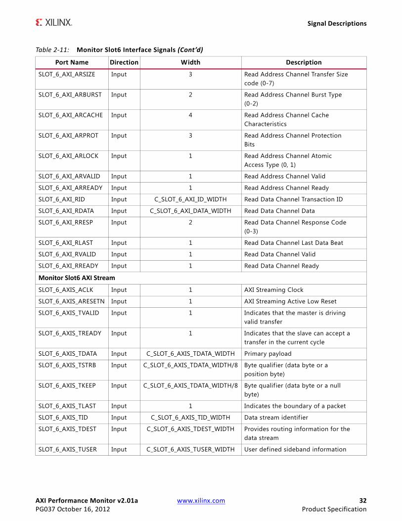
Monitor Slot6 InterfaceTable 2-11 lists the Monitor Slot 6 interface signals and these are enabled only when C_NUM_MONITOR_SLOTS >6. Monitor Slot6 AXI MM/AXI Stream ports are enabled based on SLOT 6 protocol parameter C_SLOT_6_AXI_PROTOCOL.
SLOT_5_AXI_ARLOCK Input 1 Read Address Channel AtomicAccess Type (0, 1)
SLOT_5_AXI_ARVALID Input 1 Read Address Channel Valid
SLOT_5_AXI_ARREADY Input 1 Read Address Channel Ready
SLOT_5_AXI_RID Input C_SLOT_5_AXI_ID_WIDTH Read Data Channel Transaction ID
SLOT_5_AXI_RDATA Input C_SLOT_5_AXI_DATA_WIDTH Read Data Channel Data
SLOT_5_AXI_RRESP Input 2 Read Data Channel Response Code(0-3)
SLOT_5_AXI_RLAST Input 1 Read Data Channel Last Data Beat
SLOT_5_AXI_RVALID Input 1 Read Data Channel Valid
SLOT_5_AXI_RREADY Input 1 Read Data Channel Ready
Monitor Slot5 AXI Stream
SLOT_5_AXIS_ACLK Input 1 AXI Streaming Clock
SLOT_5_AXIS_ARESETN Input 1 AXI Streaming Active Low Reset
SLOT_5_AXIS_TVALID Input 1 Indicates that the master is drivingvalid transfer
SLOT_5_AXIS_TREADY Input 1 Indicates that the slave can accept atransfer in the current cycle
SLOT_5_AXIS_TDATA Input C_SLOT_5_AXIS_TDATA_WIDTH Primary payload
SLOT_5_AXIS_TSTRB Input C_SLOT_5_AXIS_TDATA_WIDTH/8 Byte qualif ier (data byte or aposition byte)
SLOT_5_AXIS_TKEEP Input C_SLOT_5_AXIS_TDATA_WIDTH/8 Byte qualif ier (data byte or a nullbyte)
SLOT_5_AXIS_TLAST Input 1 Indicates the boundary of a packet
SLOT_5_AXIS_TID Input C_SLOT_5_AXIS_TID_WIDTH Data stream identif ier
SLOT_5_AXIS_TDEST Input C_SLOT_5_AXIS_TDEST_WIDTH Provides routing information for thedata stream
SLOT_5_AXIS_TUSER Input C_SLOT_5_AXIS_TUSER_WIDTH User defined sideband information
Table 2-10: Monitor Slot5 Interface Signals (Cont’d)
Port Name Direction Width Description

AXI Performance Monitor v2.01a www.xilinx.com 31PG037 October 16, 2012 Product Specification
Signal Descriptions
Table 2-11: Monitor Slot6 Interface Signals
Port Name Direction Width Description
Monitor Slot6 AXI MM
SLOT_6_AXI_ACLK Input 1 AXI Clock
SLOT_6_AXI_ARESETN Input 1 AXI Active Low Reset
SLOT_6_AXI_AWID Input C_SLOT_6_AXI_ID_WIDTH Write Address Channel TransactionID
SLOT_6_AXI_AWADDR Input C_SLOT_6_AXI_ADDR_WIDTH Write Address Channel Address
SLOT_6_AXI_AWPROT Input 3 Write Address Channel ProtectionBits
SLOT_6_AXI_AWLEN Input 8 Write Address Channel Burst Length(0-255)
SLOT_6_AXI_AWSIZE Input 3 Write Address Channel Transfer Sizecode (0-7)
SLOT_6_AXI_AWBURST Input 2 Write Address Channel Burst Typecode (0-2)
SLOT_6_AXI_AWCACHE Input 4 Write Address Channel CacheCharacteristics
SLOT_6_AXI_AWLOCK Input 1 Write Address Channel AtomicAccess Type (0, 1)
SLOT_6_AXI_AWVALID Input 1 Write Address Channel Valid
SLOT_6_AXI_AWREADY Input 1 Write Address Channel Ready
SLOT_6_AXI_WID Input C_SLOT_6_AXI_ID_WIDTH
SLOT_6_AXI_WDATA Input C_SLOT_6_AXI_DATA_WIDTH Write Data Channel Data
SLOT_6_AXI_WSTRB Input C_SLOT_6_AXI_DATA_WIDTH/8 Write Data Channel Byte Strobes
SLOT_6_AXI_WLAST Input 1 Write Data Channel Last Data Beat
SLOT_6_AXI_WVALID Input 1 Write Data Channel Valid
SLOT_6_AXI_WREADY Input 1 Write Data Channel Ready
SLOT_6_AXI_BID Input C_SLOT_6_AXI_ID_WIDTH Write Response Channel TransactionID
SLOT_6_AXI_BRESP Input 2 Write Response Channel ResponseCode (0-3)
SLOT_6_AXI_BVALID Input 1 Write Response Channel Valid
SLOT_6_AXI_BREADY Input 1 Write Response Channel Ready
SLOT_6_AXI_ARID Input C_SLOT_6_AXI_ID_WIDTH Read Address Channel TransactionID
SLOT_6_AXI_ARADDR Input C_SLOT_6_AXI_ADDR_WIDTH Read Address Channel Address
SLOT_6_AXI_ARLEN Input 8 Read Address Channel Burst Lengthcode(0-255)
AXI Performance Monitor v2.01a www.xilinx.com 32PG037 October 16, 2012 Product Specification
Signal Descriptions
SLOT_6_AXI_ARSIZE Input 3 Read Address Channel Transfer Sizecode (0-7)
SLOT_6_AXI_ARBURST Input 2 Read Address Channel Burst Type(0-2)
SLOT_6_AXI_ARCACHE Input 4 Read Address Channel CacheCharacteristics
SLOT_6_AXI_ARPROT Input 3 Read Address Channel ProtectionBits
SLOT_6_AXI_ARLOCK Input 1 Read Address Channel AtomicAccess Type (0, 1)
SLOT_6_AXI_ARVALID Input 1 Read Address Channel Valid
SLOT_6_AXI_ARREADY Input 1 Read Address Channel Ready
SLOT_6_AXI_RID Input C_SLOT_6_AXI_ID_WIDTH Read Data Channel Transaction ID
SLOT_6_AXI_RDATA Input C_SLOT_6_AXI_DATA_WIDTH Read Data Channel Data
SLOT_6_AXI_RRESP Input 2 Read Data Channel Response Code(0-3)
SLOT_6_AXI_RLAST Input 1 Read Data Channel Last Data Beat
SLOT_6_AXI_RVALID Input 1 Read Data Channel Valid
SLOT_6_AXI_RREADY Input 1 Read Data Channel Ready
Monitor Slot6 AXI Stream
SLOT_6_AXIS_ACLK Input 1 AXI Streaming Clock
SLOT_6_AXIS_ARESETN Input 1 AXI Streaming Active Low Reset
SLOT_6_AXIS_TVALID Input 1 Indicates that the master is drivingvalid transfer
SLOT_6_AXIS_TREADY Input 1 Indicates that the slave can accept atransfer in the current cycle
SLOT_6_AXIS_TDATA Input C_SLOT_6_AXIS_TDATA_WIDTH Primary payload
SLOT_6_AXIS_TSTRB Input C_SLOT_6_AXIS_TDATA_WIDTH/8 Byte qualif ier (data byte or aposition byte)
SLOT_6_AXIS_TKEEP Input C_SLOT_6_AXIS_TDATA_WIDTH/8 Byte qualif ier (data byte or a nullbyte)
SLOT_6_AXIS_TLAST Input 1 Indicates the boundary of a packet
SLOT_6_AXIS_TID Input C_SLOT_6_AXIS_TID_WIDTH Data stream identif ier
SLOT_6_AXIS_TDEST Input C_SLOT_6_AXIS_TDEST_WIDTH Provides routing information for thedata stream
SLOT_6_AXIS_TUSER Input C_SLOT_6_AXIS_TUSER_WIDTH User defined sideband information
Table 2-11: Monitor Slot6 Interface Signals (Cont’d)
Port Name Direction Width Description
AXI Performance Monitor v2.01a www.xilinx.com 33PG037 October 16, 2012 Product Specification
Signal Descriptions
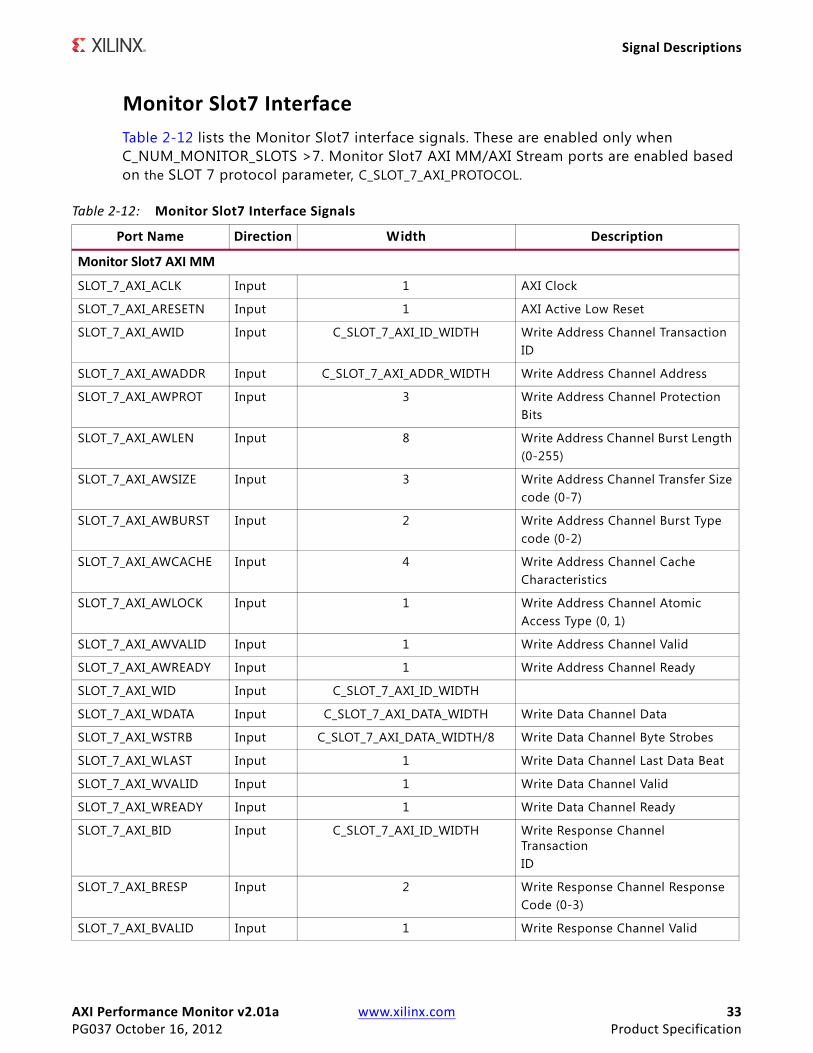
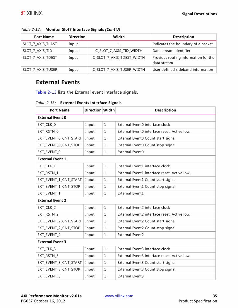
Monitor Slot7 InterfaceTable 2-12 lists the Monitor Slot7 interface signals. These are enabled only when C_NUM_MONITOR_SLOTS >7. Monitor Slot7 AXI MM/AXI Stream ports are enabled based on the SLOT 7 protocol parameter, C_SLOT_7_AXI_PROTOCOL.
Table 2-12: Monitor Slot7 Interface Signals
Port Name Direction Width Description
Monitor Slot7 AXI MM
SLOT_7_AXI_ACLK Input 1 AXI Clock
SLOT_7_AXI_ARESETN Input 1 AXI Active Low Reset
SLOT_7_AXI_AWID Input C_SLOT_7_AXI_ID_WIDTH Write Address Channel TransactionID
SLOT_7_AXI_AWADDR Input C_SLOT_7_AXI_ADDR_WIDTH Write Address Channel Address
SLOT_7_AXI_AWPROT Input 3 Write Address Channel ProtectionBits
SLOT_7_AXI_AWLEN Input 8 Write Address Channel Burst Length(0-255)
SLOT_7_AXI_AWSIZE Input 3 Write Address Channel Transfer Sizecode (0-7)
SLOT_7_AXI_AWBURST Input 2 Write Address Channel Burst Typecode (0-2)
SLOT_7_AXI_AWCACHE Input 4 Write Address Channel CacheCharacteristics
SLOT_7_AXI_AWLOCK Input 1 Write Address Channel AtomicAccess Type (0, 1)
SLOT_7_AXI_AWVALID Input 1 Write Address Channel Valid
SLOT_7_AXI_AWREADY Input 1 Write Address Channel Ready
SLOT_7_AXI_WID Input C_SLOT_7_AXI_ID_WIDTH
SLOT_7_AXI_WDATA Input C_SLOT_7_AXI_DATA_WIDTH Write Data Channel Data
SLOT_7_AXI_WSTRB Input C_SLOT_7_AXI_DATA_WIDTH/8 Write Data Channel Byte Strobes
SLOT_7_AXI_WLAST Input 1 Write Data Channel Last Data Beat
SLOT_7_AXI_WVALID Input 1 Write Data Channel Valid
SLOT_7_AXI_WREADY Input 1 Write Data Channel Ready
SLOT_7_AXI_BID Input C_SLOT_7_AXI_ID_WIDTH Write Response Channel TransactionID
SLOT_7_AXI_BRESP Input 2 Write Response Channel ResponseCode (0-3)
SLOT_7_AXI_BVALID Input 1 Write Response Channel Valid

AXI Performance Monitor v2.01a www.xilinx.com 34PG037 October 16, 2012 Product Specification
Signal Descriptions
SLOT_7_AXI_BREADY Input 1 Write Response Channel Ready
SLOT_7_AXI_ARID Input C_SLOT_7_AXI_ID_WIDTH Read Address Channel TransactionID
SLOT_7_AXI_ARADDR Input C_SLOT_7_AXI_ADDR_WIDTH Read Address Channel Address
SLOT_7_AXI_ARLEN Input 8 Read Address Channel Burst Lengthcode(0-255)
SLOT_7_AXI_ARSIZE Input 3 Read Address Channel Transfer Sizecode (0-7)
SLOT_7_AXI_ARBURST Input 2 Read Address Channel Burst Type(0-2)
SLOT_7_AXI_ARCACHE Input 4 Read Address Channel CacheCharacteristics
SLOT_7_AXI_ARPROT Input 3 Read Address Channel ProtectionBits
SLOT_7_AXI_ARLOCK Input 1 Read Address Channel AtomicAccess Type (0, 1)
SLOT_7_AXI_ARVALID Input 1 Read Address Channel Valid
SLOT_7_AXI_ARREADY Input 1 Read Address Channel Ready
SLOT_7_AXI_RID Input C_SLOT_7_AXI_ID_WIDTH Read Data Channel Transaction ID
SLOT_7_AXI_RDATA Input C_SLOT_7_AXI_DATA_WIDTH Read Data Channel Data
SLOT_7_AXI_RRESP Input 2 Read Data Channel Response Code(0-3)
SLOT_7_AXI_RLAST Input 1 Read Data Channel Last Data Beat
SLOT_7_AXI_RVALID Input 1 Read Data Channel Valid
SLOT_7_AXI_RREADY Input 1 Read Data Channel Ready
Monitor Slot7 AXI Stream
SLOT_7_AXIS_ACLK Input 1 AXI Streaming Clock
SLOT_7_AXIS_ARESETN Input 1 AXI Streaming Active Low Reset
SLOT_7_AXIS_TVALID Input 1 Indicates that the master is drivingvalid transfer
SLOT_7_AXIS_TREADY Input 1 Indicates that the slave can accept atransfer in the current cycle
SLOT_7_AXIS_TDATA Input C_SLOT_7_AXIS_TDATA_WIDTH Primary payload
SLOT_7_AXIS_TSTRB Input C_SLOT_7_AXIS_TDATA_WIDTH/8 Byte qualif ier (data byte or aposition byte)
SLOT_7_AXIS_TKEEP Input C_SLOT_7_AXIS_TDATA_WIDTH/8 Byte qualif ier (data byte or a nullbyte)
Table 2-12: Monitor Slot7 Interface Signals (Cont’d)
Port Name Direction Width Description
AXI Performance Monitor v2.01a www.xilinx.com 35PG037 October 16, 2012 Product Specification
Signal Descriptions
External EventsTable 2-13 lists the External event interface signals.
SLOT_7_AXIS_TLAST Input 1 Indicates the boundary of a packet
SLOT_7_AXIS_TID Input C_SLOT_7_AXIS_TID_WIDTH Data stream identif ier
SLOT_7_AXIS_TDEST Input C_SLOT_7_AXIS_TDEST_WIDTH Provides routing information for thedata stream
SLOT_7_AXIS_TUSER Input C_SLOT_7_AXIS_TUSER_WIDTH User defined sideband information
Table 2-12: Monitor Slot7 Interface Signals (Cont’d)
Port Name Direction Width Description
Table 2-13: External Events Interface Signals
Port Name Direction Width Description
External Event 0
EXT_CLK_0 Input 1 External Event0 interface clock
EXT_RSTN_0 Input 1 External Event0 interface reset. Active low.
EXT_EVENT_0_CNT_START Input 1 External Event0 Count start signal
EXT_EVENT_0_CNT_STOP Input 1 External Event0 Count stop signal
EXT_EVENT_0 Input 1 External Event0
External Event 1
EXT_CLK_1 Input 1 External Event1 interface clock
EXT_RSTN_1 Input 1 External Event1 interface reset. Active low.
EXT_EVENT_1_CNT_START Input 1 External Event1 Count start signal
EXT_EVENT_1_CNT_STOP Input 1 External Event1 Count stop signal
EXT_EVENT_1 Input 1 External Event1
External Event 2
EXT_CLK_2 Input 1 External Event2 interface clock
EXT_RSTN_2 Input 1 External Event2 interface reset. Active low.
EXT_EVENT_2_CNT_START Input 1 External Event2 Count start signal
EXT_EVENT_2_CNT_STOP Input 1 External Event2 Count stop signal
EXT_EVENT_2 Input 1 External Event2
External Event 3
EXT_CLK_3 Input 1 External Event3 interface clock
EXT_RSTN_3 Input 1 External Event3 interface reset. Active low.
EXT_EVENT_3_CNT_START Input 1 External Event3 Count start signal
EXT_EVENT_3_CNT_STOP Input 1 External Event3 Count stop signal
EXT_EVENT_3 Input 1 External Event3
AXI Performance Monitor v2.01a www.xilinx.com 36PG037 October 16, 2012 Product Specification
Signal Descriptions
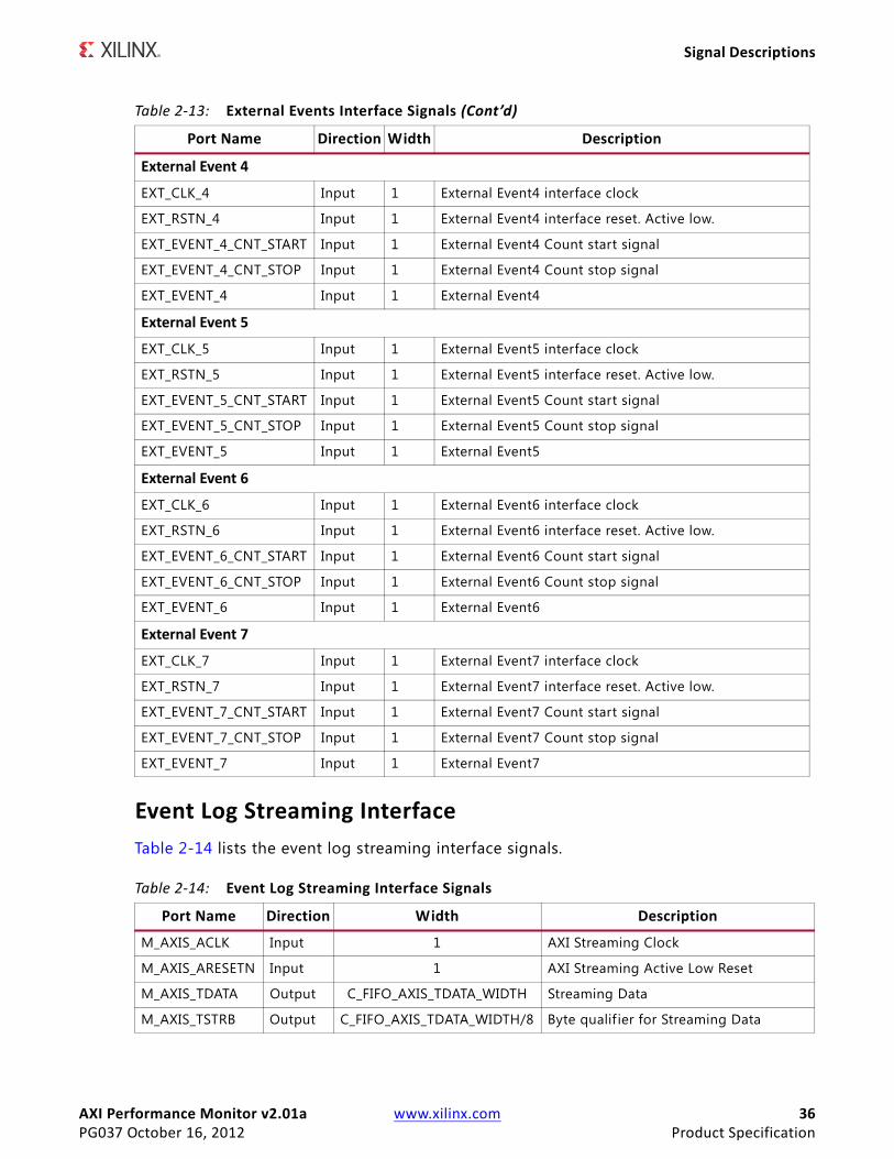
Event Log Streaming InterfaceTable 2-14 lists the event log streaming interface signals.
External Event 4
EXT_CLK_4 Input 1 External Event4 interface clock
EXT_RSTN_4 Input 1 External Event4 interface reset. Active low.
EXT_EVENT_4_CNT_START Input 1 External Event4 Count start signal
EXT_EVENT_4_CNT_STOP Input 1 External Event4 Count stop signal
EXT_EVENT_4 Input 1 External Event4
External Event 5
EXT_CLK_5 Input 1 External Event5 interface clock
EXT_RSTN_5 Input 1 External Event5 interface reset. Active low.
EXT_EVENT_5_CNT_START Input 1 External Event5 Count start signal
EXT_EVENT_5_CNT_STOP Input 1 External Event5 Count stop signal
EXT_EVENT_5 Input 1 External Event5
External Event 6
EXT_CLK_6 Input 1 External Event6 interface clock
EXT_RSTN_6 Input 1 External Event6 interface reset. Active low.
EXT_EVENT_6_CNT_START Input 1 External Event6 Count start signal
EXT_EVENT_6_CNT_STOP Input 1 External Event6 Count stop signal
EXT_EVENT_6 Input 1 External Event6
External Event 7
EXT_CLK_7 Input 1 External Event7 interface clock
EXT_RSTN_7 Input 1 External Event7 interface reset. Active low.
EXT_EVENT_7_CNT_START Input 1 External Event7 Count start signal
EXT_EVENT_7_CNT_STOP Input 1 External Event7 Count stop signal
EXT_EVENT_7 Input 1 External Event7
Table 2-14: Event Log Streaming Interface Signals
Port Name Direction Width Description
M_AXIS_ACLK Input 1 AXI Streaming Clock
M_AXIS_ARESETN Input 1 AXI Streaming Active Low Reset
M_AXIS_TDATA Output C_FIFO_AXIS_TDATA_WIDTH Streaming Data
M_AXIS_TSTRB Output C_FIFO_AXIS_TDATA_WIDTH/8 Byte qualif ier for Streaming Data
Table 2-13: External Events Interface Signals (Cont’d)
Port Name Direction Width Description

AXI Performance Monitor v2.01a www.xilinx.com 37PG037 October 16, 2012 Product Specification
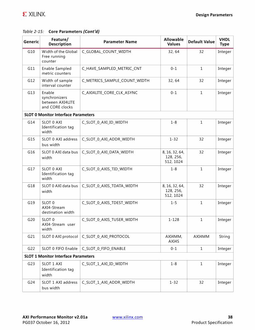
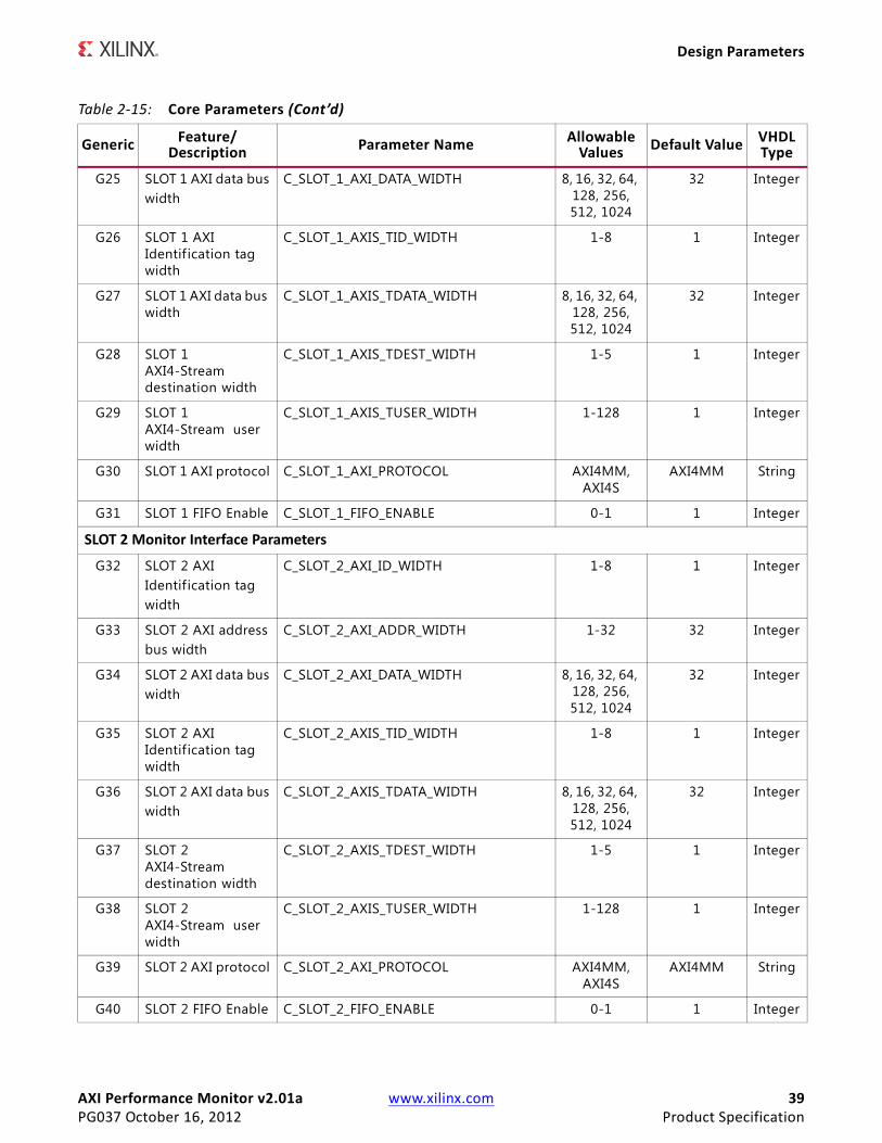
Design Parameters
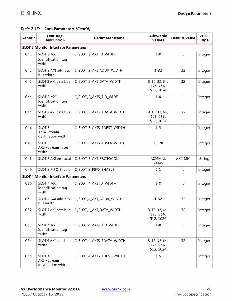
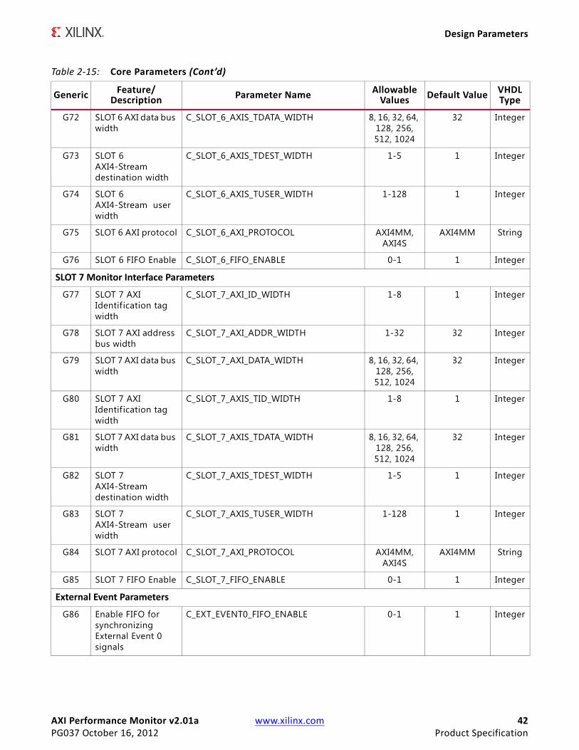
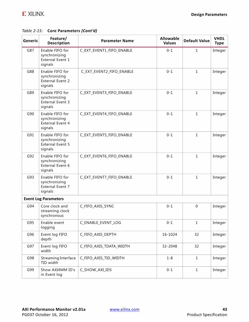
Design ParametersTable 2-15 describes the core design parameters.
M_AXIS_TVALID Output 1 Indicates that the master is drivingvalid transfer
M_AXIS_TID Output C_FIFO_AXIS_TID_WIDTH Data stream identif ier
M_AXIS_TREADY Input 1 Indicates that the slave can accept atransfer in the current cycle
Table 2-14: Event Log Streaming Interface Signals (Cont’d)
Port Name Direction Width Description
Table 2-15: Core Parameters
Generic Feature/Description Parameter Name Allowable
Values Default Value VHDLType
System Parameters
G1 Target FPGA family C_FAMILY Zynq, Artix7,
Kintex7, Virtex7,Virtex6,
Spartan 6
Virtex7 string
G2 Instance name C_INSTANCE axi_perf_mon string
AXI4-Lite Interface Parameters
G3 AXI addressbus width
C_S_AXI_ADDR_WIDTH 16 16 Integer
G4 AXI data buswidth
C_S_AXI_DATA_WIDTH 32 32 Integer
G5 AXI interface type C_S_AXI_PROTOCOL AXI4LITE AXI4LITE String
Monitors and Event Counter Parameters
G6 Number of monitor slots/external events
C_NUM_MONITOR_SLOTS 1-8 1 Integer
G7 Register all monitor input signals
C_REG_ALL_MONITOR_SIGNALS 0-1 1 Integer
G8 Enable Event Count module
C_ENABLE_EVENT_COUNT 0-1 1 Integer
G9 Number of metric counters
C_NUM_OF_COUNTERS 1-10 1 Integer
AXI Performance Monitor v2.01a www.xilinx.com 38PG037 October 16, 2012 Product Specification
Design Parameters
G10 Width of the Global Free running counter
C_GLOBAL_COUNT_WIDTH 32, 64 32 Integer
G11 Enable Sampled metric counters
C_HAVE_SAMPLED_METRIC_CNT 0-1 1 Integer
G12 Width of sample interval counter
C_METRICS_SAMPLE_COUNT_WIDTH 32, 64 32 Integer
G13 Enable synchronizers between AXI4LITE and CORE clocks
C_AXI4LITE_CORE_CLK_ASYNC 0-1 1 Integer
SLOT 0 Monitor Interface Parameters
G14 SLOT 0 AXI Identif ication tag width
C_SLOT_0_AXI_ID_WIDTH 1-8 1 Integer
G15 SLOT 0 AXI addressbus width
C_SLOT_0_AXI_ADDR_WIDTH 1-32 32 Integer
G16 SLOT 0 AXI data buswidth
C_SLOT_0_AXI_DATA_WIDTH 8, 16, 32, 64, 128, 256, 512, 1024
32 Integer
G17 SLOT 0 AXI Identif ication tag width
C_SLOT_0_AXIS_TID_WIDTH 1-8 1 Integer
G18 SLOT 0 AXI data buswidth
C_SLOT_0_AXIS_TDATA_WIDTH 8, 16, 32, 64, 128, 256, 512, 1024
32 Integer
G19 SLOT 0 AXI4-Stream destination width
C_SLOT_0_AXIS_TDEST_WIDTH 1-5 1 Integer
G20 SLOT 0 AXI4-Stream user width
C_SLOT_0_AXIS_TUSER_WIDTH 1-128 1 Integer
G21 SLOT 0 AXI protocol C_SLOT_0_AXI_PROTOCOL AXI4MM, AXI4S
AXI4MM String
G22 SLOT 0 FIFO Enable C_SLOT_0_FIFO_ENABLE 0-1 1 Integer
SLOT 1 Monitor Interface Parameters
G23 SLOT 1 AXIIdentif ication tagwidth
C_SLOT_1_AXI_ID_WIDTH 1-8 1 Integer
G24 SLOT 1 AXI addressbus width
C_SLOT_1_AXI_ADDR_WIDTH 1-32 32 Integer
Table 2-15: Core Parameters (Cont’d)
Generic Feature/Description Parameter Name Allowable
Values Default Value VHDLType
AXI Performance Monitor v2.01a www.xilinx.com 39PG037 October 16, 2012 Product Specification
Design Parameters
G25 SLOT 1 AXI data buswidth
C_SLOT_1_AXI_DATA_WIDTH 8, 16, 32, 64, 128, 256, 512, 1024
32 Integer
G26 SLOT 1 AXI Identif ication tag width
C_SLOT_1_AXIS_TID_WIDTH 1-8 1 Integer
G27 SLOT 1 AXI data bus width
C_SLOT_1_AXIS_TDATA_WIDTH 8, 16, 32, 64, 128, 256, 512, 1024
32 Integer
G28 SLOT 1 AXI4-Stream destination width
C_SLOT_1_AXIS_TDEST_WIDTH 1-5 1 Integer
G29 SLOT 1 AXI4-Stream user width
C_SLOT_1_AXIS_TUSER_WIDTH 1-128 1 Integer
G30 SLOT 1 AXI protocol C_SLOT_1_AXI_PROTOCOL AXI4MM, AXI4S
AXI4MM String
G31 SLOT 1 FIFO Enable C_SLOT_1_FIFO_ENABLE 0-1 1 Integer
SLOT 2 Monitor Interface Parameters
G32 SLOT 2 AXIIdentif ication tagwidth
C_SLOT_2_AXI_ID_WIDTH 1-8 1 Integer
G33 SLOT 2 AXI addressbus width
C_SLOT_2_AXI_ADDR_WIDTH 1-32 32 Integer
G34 SLOT 2 AXI data buswidth
C_SLOT_2_AXI_DATA_WIDTH 8, 16, 32, 64, 128, 256, 512, 1024
32 Integer
G35 SLOT 2 AXI Identif ication tag width
C_SLOT_2_AXIS_TID_WIDTH 1-8 1 Integer
G36 SLOT 2 AXI data buswidth
C_SLOT_2_AXIS_TDATA_WIDTH 8, 16, 32, 64, 128, 256, 512, 1024
32 Integer
G37 SLOT 2 AXI4-Stream destination width
C_SLOT_2_AXIS_TDEST_WIDTH 1-5 1 Integer
G38 SLOT 2 AXI4-Stream user width
C_SLOT_2_AXIS_TUSER_WIDTH 1-128 1 Integer
G39 SLOT 2 AXI protocol C_SLOT_2_AXI_PROTOCOL AXI4MM, AXI4S
AXI4MM String
G40 SLOT 2 FIFO Enable C_SLOT_2_FIFO_ENABLE 0-1 1 Integer
Table 2-15: Core Parameters (Cont’d)
Generic Feature/Description Parameter Name Allowable
Values Default Value VHDLType
AXI Performance Monitor v2.01a www.xilinx.com 40PG037 October 16, 2012 Product Specification
Design Parameters
SLOT 3 Monitor Interface Parameters
G41 SLOT 3 AXIIdentif ication tag width
C_SLOT_3_AXI_ID_WIDTH 1-8 1 Integer
G42 SLOT 3 AXI address bus width
C_SLOT_3_AXI_ADDR_WIDTH 1-32 32 Integer
G43 SLOT 3 AXI data bus width
C_SLOT_3_AXI_DATA_WIDTH 8, 16, 32, 64, 128, 256, 512, 1024
32 Integer
G44 SLOT 3 AXI Identif ication tag width
C_SLOT_3_AXIS_TID_WIDTH 1-8 1 Integer
G45 SLOT 3 AXI data bus width
C_SLOT_3_AXIS_TDATA_WIDTH 8, 16, 32, 64, 128, 256, 512, 1024
32 Integer
G46 SLOT 3 AXI4-Stream destination width
C_SLOT_3_AXIS_TDEST_WIDTH 1-5 1 Integer
G47 SLOT 3 AXI4-Stream user width
C_SLOT_3_AXIS_TUSER_WIDTH 1-128 1 Integer
G48 SLOT 3 AXI protocol C_SLOT_3_AXI_PROTOCOL AXI4MM, AXI4S
AXI4MM String
G49 SLOT 3 FIFO Enable C_SLOT_3_FIFO_ENABLE 0-1 1 Integer
SLOT 4 Monitor Interface Parameters
G50 SLOT 4 AXI Identif ication tag width
C_SLOT_4_AXI_ID_WIDTH 1-8 1 Integer
G51 SLOT 4 AXI address bus width
C_SLOT_4_AXI_ADDR_WIDTH 1-32 32 Integer
G52 SLOT 4 AXI data bus width
C_SLOT_4_AXI_DATA_WIDTH 8, 16, 32, 64, 128, 256, 512, 1024
32 Integer
G53 SLOT 4 AXI Identif ication tag width
C_SLOT_4_AXIS_TID_WIDTH 1-8 1 Integer
G54 SLOT 4 AXI data bus width
C_SLOT_4_AXIS_TDATA_WIDTH 8, 16, 32, 64, 128, 256, 512, 1024
32 Integer
G55 SLOT 4 AXI4-Stream destination width
C_SLOT_4_AXIS_TDEST_WIDTH 1-5 1 Integer
Table 2-15: Core Parameters (Cont’d)
Generic Feature/Description Parameter Name Allowable
Values Default Value VHDLType

AXI Performance Monitor v2.01a www.xilinx.com 41PG037 October 16, 2012 Product Specification
Design Parameters
G56 SLOT 4 AXI4-Stream user width
C_SLOT_4_AXIS_TUSER_WIDTH 1-128 1 Integer
G57 SLOT 4 AXI protocol C_SLOT_4_AXI_PROTOCOL AXI4MM, AXI4S
AXI4MM String
G58 SLOT 4 FIFO Enable C_SLOT_4_FIFO_ENABLE 0-1 1 Integer
SLOT 5 Monitor Interface Parameters
G59 SLOT 5 AXI Identif ication tag width
C_SLOT_5_AXI_ID_WIDTH 1-8 1 Integer
G60 SLOT 5 AXI address bus width
C_SLOT_5_AXI_ADDR_WIDTH 1-32 32 Integer
G61 SLOT 5 AXI data bus width
C_SLOT_5_AXI_DATA_WIDTH 8, 16, 32, 64, 128, 256, 512, 1024
32 Integer
G62 SLOT 5 AXI Identif ication tag width
C_SLOT_5_AXIS_TID_WIDTH 1-8 1 Integer
G63 SLOT 5 AXI data bus width
C_SLOT_5_AXIS_TDATA_WIDTH 8, 16, 32, 64, 128, 256, 512, 1024
32 Integer
G64 SLOT 5 AXI4-Stream destination width
C_SLOT_5_AXIS_TDEST_WIDTH 1-5 1 Integer
G65 SLOT 5 AXI4-Stream user width
C_SLOT_5_AXIS_TUSER_WIDTH 1-128 1 Integer
G66 SLOT 5 AXI protocol C_SLOT_5_AXI_PROTOCOL AXI4MM, AXI4S
AXI4MM String
G67 SLOT 5 FIFO Enable C_SLOT_5_FIFO_ENABLE 0-1 1 Integer
SLOT 6 Monitor Interface Parameters
G68 SLOT 6 AXI Identif ication tag width
C_SLOT_6_AXI_ID_WIDTH 1-8 1 Integer
G69 SLOT 6 AXI address bus width
C_SLOT_6_AXI_ADDR_WIDTH 1-32 32 Integer
G70 SLOT 6 AXI data bus width
C_SLOT_6_AXI_DATA_WIDTH 8, 16, 32, 64, 128, 256, 512, 1024
32 Integer
G71 SLOT 6 AXI Identif ication tag width
C_SLOT_6_AXIS_TID_WIDTH 1-8 1 Integer
Table 2-15: Core Parameters (Cont’d)
Generic Feature/Description Parameter Name Allowable
Values Default Value VHDLType
AXI Performance Monitor v2.01a www.xilinx.com 42PG037 October 16, 2012 Product Specification
Design Parameters
G72 SLOT 6 AXI data bus width
C_SLOT_6_AXIS_TDATA_WIDTH 8, 16, 32, 64, 128, 256, 512, 1024
32 Integer
G73 SLOT 6 AXI4-Stream destination width
C_SLOT_6_AXIS_TDEST_WIDTH 1-5 1 Integer
G74 SLOT 6 AXI4-Stream user width
C_SLOT_6_AXIS_TUSER_WIDTH 1-128 1 Integer
G75 SLOT 6 AXI protocol C_SLOT_6_AXI_PROTOCOL AXI4MM, AXI4S
AXI4MM String
G76 SLOT 6 FIFO Enable C_SLOT_6_FIFO_ENABLE 0-1 1 Integer
SLOT 7 Monitor Interface Parameters
G77 SLOT 7 AXI Identif ication tag width
C_SLOT_7_AXI_ID_WIDTH 1-8 1 Integer
G78 SLOT 7 AXI address bus width
C_SLOT_7_AXI_ADDR_WIDTH 1-32 32 Integer
G79 SLOT 7 AXI data bus width
C_SLOT_7_AXI_DATA_WIDTH 8, 16, 32, 64, 128, 256, 512, 1024
32 Integer
G80 SLOT 7 AXI Identif ication tag width
C_SLOT_7_AXIS_TID_WIDTH 1-8 1 Integer
G81 SLOT 7 AXI data bus width
C_SLOT_7_AXIS_TDATA_WIDTH 8, 16, 32, 64, 128, 256, 512, 1024
32 Integer
G82 SLOT 7 AXI4-Stream destination width
C_SLOT_7_AXIS_TDEST_WIDTH 1-5 1 Integer
G83 SLOT 7 AXI4-Stream user width
C_SLOT_7_AXIS_TUSER_WIDTH 1-128 1 Integer
G84 SLOT 7 AXI protocol C_SLOT_7_AXI_PROTOCOL AXI4MM, AXI4S
AXI4MM String
G85 SLOT 7 FIFO Enable C_SLOT_7_FIFO_ENABLE 0-1 1 Integer
External Event Parameters
G86 Enable FIFO for synchronizing External Event 0 signals
C_EXT_EVENT0_FIFO_ENABLE 0-1 1 Integer
Table 2-15: Core Parameters (Cont’d)
Generic Feature/Description Parameter Name Allowable
Values Default Value VHDLType
AXI Performance Monitor v2.01a www.xilinx.com 43PG037 October 16, 2012 Product Specification
Design Parameters
G87 Enable FIFO for synchronizing External Event 1 signals
C_EXT_EVENT1_FIFO_ENABLE 0-1 1 Integer
G88 Enable FIFO for synchronizing External Event 2 signals
C_EXT_EVENT2_FIFO_ENABLE 0-1 1 Integer
G89 Enable FIFO for synchronizing External Event 3 signals
C_EXT_EVENT3_FIFO_ENABLE 0-1 1 Integer
G90 Enable FIFO for synchronizing External Event 4 signals
C_EXT_EVENT4_FIFO_ENABLE 0-1 1 Integer
G91 Enable FIFO for synchronizing External Event 5 signals
C_EXT_EVENT5_FIFO_ENABLE 0-1 1 Integer
G92 Enable FIFO for synchronizing External Event 6 signals
C_EXT_EVENT6_FIFO_ENABLE 0-1 1 Integer
G93 Enable FIFO for synchronizing External Event 7 signals
C_EXT_EVENT7_FIFO_ENABLE 0-1 1 Integer
Event Log Parameters
G94 Core clock and streaming clock synchronous
C_FIFO_AXIS_SYNC 0-1 0 Integer
G95 Enable event logging
C_ENABLE_EVENT_LOG 0-1 1 Integer
G96 Event log FIFO depth
C_FIFO_AXIS_DEPTH 16-1024 32 Integer
G97 Event log FIFO width
C_FIFO_AXIS_TDATA_WIDTH 32-2048 32 Integer
G98 Streaming Interface TID width
C_FIFO_AXIS_TID_WIDTH 1-8 1 Integer
G99 Show AXI4MM ID's in Event log
C_SHOW_AXI_IDS 0-1 1 Integer
Table 2-15: Core Parameters (Cont’d)
Generic Feature/Description Parameter Name Allowable
Values Default Value VHDLType
AXI Performance Monitor v2.01a www.xilinx.com 44PG037 October 16, 2012 Product Specification
Register Space
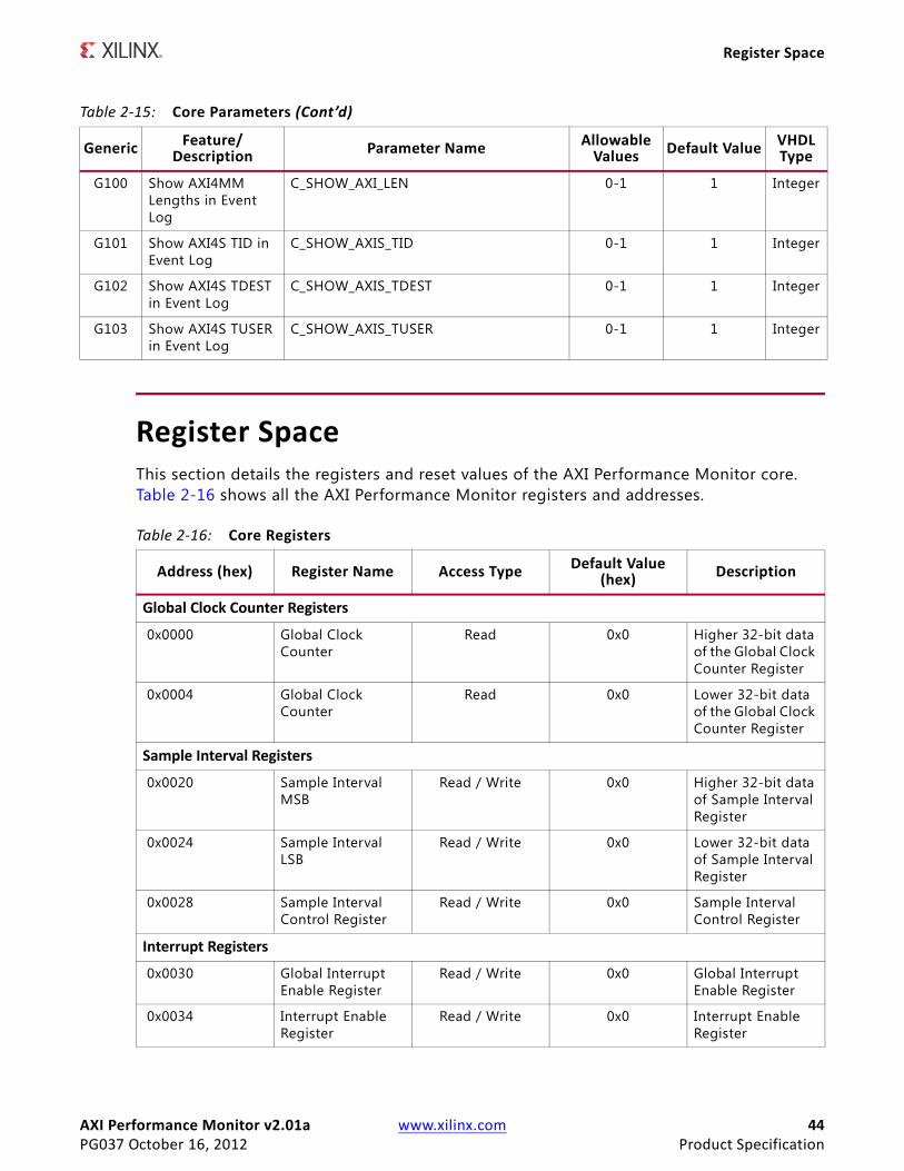
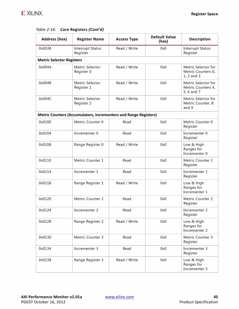
Register SpaceThis section details the registers and reset values of the AXI Performance Monitor core. Table 2-16 shows all the AXI Performance Monitor registers and addresses.
G100 Show AXI4MM Lengths in Event Log
C_SHOW_AXI_LEN 0-1 1 Integer
G101 Show AXI4S TID in Event Log
C_SHOW_AXIS_TID 0-1 1 Integer
G102 Show AXI4S TDEST in Event Log
C_SHOW_AXIS_TDEST 0-1 1 Integer
G103 Show AXI4S TUSER in Event Log
C_SHOW_AXIS_TUSER 0-1 1 Integer
Table 2-15: Core Parameters (Cont’d)
Generic Feature/Description Parameter Name Allowable
Values Default Value VHDLType
Table 2-16: Core Registers
Address (hex) Register Name Access Type Default Value (hex) Description
Global Clock Counter Registers
0x0000 Global Clock Counter
Read 0x0 Higher 32-bit data of the Global Clock Counter Register
0x0004 Global Clock Counter
Read 0x0 Lower 32-bit data of the Global Clock Counter Register
Sample Interval Registers
0x0020 Sample Interval MSB
Read / Write 0x0 Higher 32-bit data of Sample Interval Register
0x0024 Sample Interval LSB
Read / Write 0x0 Lower 32-bit data of Sample Interval Register
0x0028 Sample Interval Control Register
Read / Write 0x0 Sample Interval Control Register
Interrupt Registers
0x0030 Global Interrupt Enable Register
Read / Write 0x0 Global Interrupt Enable Register
0x0034 Interrupt Enable Register
Read / Write 0x0 Interrupt Enable Register
AXI Performance Monitor v2.01a www.xilinx.com 45PG037 October 16, 2012 Product Specification
Register Space
0x0038 Interrupt Status Register
Read / Write 0x0 Interrupt Status Register
Metric Selector Registers
0x0044 Metric Selector Register 0
Read / Write 0x0 Metric Selector for Metric Counters 0, 1, 2 and 3
0x0048 Metric Selector Register 1
Read / Write 0x0 Metric Selector for Metric Counters 4, 5, 6 and 7
0x004C Metric Selector Register 2
Read / Write 0x0 Metric Selector for Metric Counter, 8 and 9
Metric Counters (Accumulators, Incrementers and Range Registers)
0x0100 Metric Counter 0 Read 0x0 Metric Counter 0 Register
0x0104 Incrementer 0 Read 0x0 Incrementer 0 Register
0x0108 Range Register 0 Read / Write 0x0 Low & High Ranges for Incrementer 0
0x0110 Metric Counter 1 Read 0x0 Metric Counter 1 Register
0x0114 Incrementer 1 Read 0x0 Incrementer 1 Register
0x0118 Range Register 1 Read / Write 0x0 Low & High Ranges for Incrementer 1
0x0120 Metric Counter 2 Read 0x0 Metric Counter 2 Register
0x0124 Incrementer 2 Read 0x0 Incrementer 2 Register
0x0128 Range Register 2 Read / Write 0x0 Low & High Ranges for Incrementer 2
0x0130 Metric Counter 3 Read 0x0 Metric Counter 3 Register
0x0134 Incrementer 3 Read 0x0 Incrementer 3 Register
0x0138 Range Register 3 Read / Write 0x0 Low & High Ranges for Incrementer 3
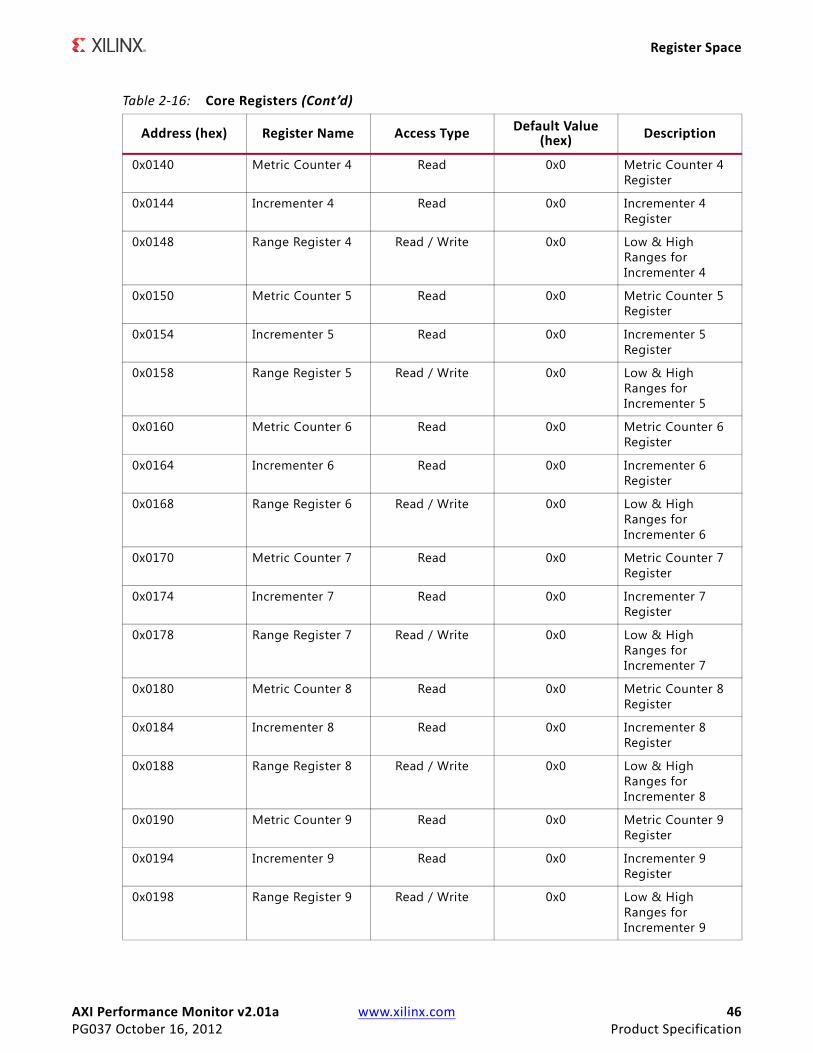
Table 2-16: Core Registers (Cont’d)
Address (hex) Register Name Access Type Default Value (hex) Description
AXI Performance Monitor v2.01a www.xilinx.com 46PG037 October 16, 2012 Product Specification
Register Space
0x0140 Metric Counter 4 Read 0x0 Metric Counter 4 Register
0x0144 Incrementer 4 Read 0x0 Incrementer 4 Register
0x0148 Range Register 4 Read / Write 0x0 Low & High Ranges for Incrementer 4
0x0150 Metric Counter 5 Read 0x0 Metric Counter 5 Register
0x0154 Incrementer 5 Read 0x0 Incrementer 5 Register
0x0158 Range Register 5 Read / Write 0x0 Low & High Ranges for Incrementer 5
0x0160 Metric Counter 6 Read 0x0 Metric Counter 6 Register
0x0164 Incrementer 6 Read 0x0 Incrementer 6 Register
0x0168 Range Register 6 Read / Write 0x0 Low & High Ranges for Incrementer 6
0x0170 Metric Counter 7 Read 0x0 Metric Counter 7 Register
0x0174 Incrementer 7 Read 0x0 Incrementer 7 Register
0x0178 Range Register 7 Read / Write 0x0 Low & High Ranges for Incrementer 7
0x0180 Metric Counter 8 Read 0x0 Metric Counter 8 Register
0x0184 Incrementer 8 Read 0x0 Incrementer 8 Register
0x0188 Range Register 8 Read / Write 0x0 Low & High Ranges for Incrementer 8
0x0190 Metric Counter 9 Read 0x0 Metric Counter 9 Register
0x0194 Incrementer 9 Read 0x0 Incrementer 9 Register
0x0198 Range Register 9 Read / Write 0x0 Low & High Ranges for Incrementer 9
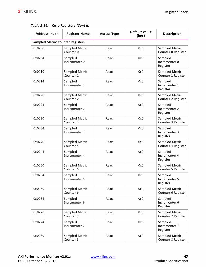
Table 2-16: Core Registers (Cont’d)
Address (hex) Register Name Access Type Default Value (hex) Description
AXI Performance Monitor v2.01a www.xilinx.com 47PG037 October 16, 2012 Product Specification
Register Space
Sampled Metric Counter Registers
0x0200 Sampled Metric Counter 0
Read 0x0 Sampled Metric Counter 0 Register
0x0204 Sampled Incrementer 0
Read 0x0 Sampled Incrementer 0 Register
0x0210 Sampled Metric Counter 1
Read 0x0 Sampled Metric Counter 1 Register
0x0214 Sampled Incrementer 1
Read 0x0 Sampled Incrementer 1 Register
0x0220 Sampled Metric Counter 2
Read 0x0 Sampled Metric Counter 2 Register
0x0224 Sampled Incrementer 2
Read 0x0 Sampled Incrementer 2 Register
0x0230 Sampled Metric Counter 3
Read 0x0 Sampled Metric Counter 3 Register
0x0234 Sampled Incrementer 3
Read 0x0 Sampled Incrementer 3 Register
0x0240 Sampled Metric Counter 4
Read 0x0 Sampled Metric Counter 4 Register
0x0244 Sampled Incrementer 4
Read 0x0 Sampled Incrementer 4 Register
0x0250 Sampled Metric Counter 5
Read 0x0 Sampled Metric Counter 5 Register
0x0254 Sampled Incrementer 5
Read 0x0 Sampled Incrementer 5 Register
0x0260 Sampled Metric Counter 6
Read 0x0 Sampled Metric Counter 6 Register
0x0264 Sampled Incrementer 6
Read 0x0 Sampled Incrementer 6 Register
0x0270 Sampled Metric Counter 7
Read 0x0 Sampled Metric Counter 7 Register
0x0274 Sampled Incrementer 7
Read 0x0 Sampled Incrementer 7 Register
0x0280 Sampled Metric Counter 8
Read 0x0 Sampled Metric Counter 8 Register
Table 2-16: Core Registers (Cont’d)
Address (hex) Register Name Access Type Default Value (hex) Description

AXI Performance Monitor v2.01a www.xilinx.com 48PG037 October 16, 2012 Product Specification
Register Space
Global Clock Count RegisterThe Global Clock Count is a 32/64 read register. This register holds the total number of simulation cycles. The bit definition and accessibility of this register are shown in Table 2-17.
Sample Interval RegisterThe Sample Interval is a 32/64-bit read/write register. This register holds the load value for the sample interval down counter used in generating a capture event for capturing the metric counters into Sampled Metric Counter registers. The bit definition and accessibility of this register is shown in Table 2-18.
0x0284 Sampled Incrementer 8
Read 0x0 Sampled Incrementer 8 Register
0x0290 Sampled Metric Counter 9
Read 0x0 Sampled Metric Counter 9 Register
0x0294 Sampled Incrementer 9
Read 0x0 Sampled Incrementer 9 Register
CONTROL Register
0x0300 Control Register Read / Write 0x0 Control Register
Event Log Registers
0x0400 Flag Enable Register
Read / Write 0x0 Flag Enable Register
0x0404 Software-written Data Register
Read / Write 0x0 Software-written Data Register
Table 2-17: Global Clock Count Register Bit Definitions (0x0004)
Bit Name Access Reset Value Description
63-32 Global Clock Count Read 0x00 Higher 32-bits of Global Clock Count Register
31-0 Global Clock Count Read 0x00 Lower 32-bits of Global Clock Count Register
Notes: 1. If parameter C_S_AXI_DATA_WIDTH is 32, the register can be read by a read transaction to two locations: (0x0000)
and (0x0004).2. If C_GLOBAL_COUNT_WIDTH=32, only the lower 32 bits of the register are valid.3. If C_GLOBAL_COUNT_WIDTH=64, then all 64 bits of the register are valid.
Table 2-16: Core Registers (Cont’d)
Address (hex) Register Name Access Type Default Value (hex) Description
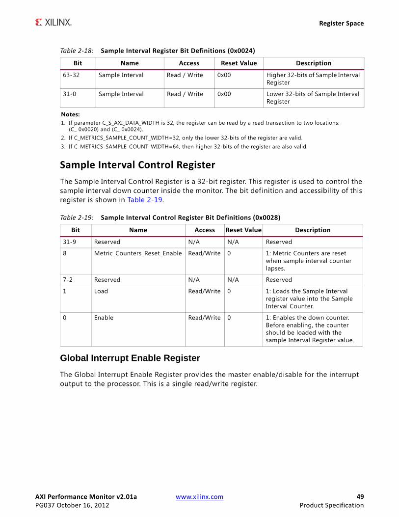
AXI Performance Monitor v2.01a www.xilinx.com 49PG037 October 16, 2012 Product Specification
Register Space
Sample Interval Control RegisterThe Sample Interval Control Register is a 32-bit register. This register is used to control the sample interval down counter inside the monitor. The bit definition and accessibility of this register is shown in Table 2-19.
Global Interrupt Enable RegisterThe Global Interrupt Enable Register provides the master enable/disable for the interrupt output to the processor. This is a single read/write register.
Table 2-18: Sample Interval Register Bit Definitions (0x0024)
Bit Name Access Reset Value Description
63-32 Sample Interval Read / Write 0x00 Higher 32-bits of Sample Interval Register
31-0 Sample Interval Read / Write 0x00 Lower 32-bits of Sample Interval Register
Notes: 1. If parameter C_S_AXI_DATA_WIDTH is 32, the register can be read by a read transaction to two locations:
(C_ 0x0020) and (C_ 0x0024).2. If C_METRICS_SAMPLE_COUNT_WIDTH=32, only the lower 32-bits of the register are valid.3. If C_METRICS_SAMPLE_COUNT_WIDTH=64, then higher 32-bits of the register are also valid.
Table 2-19: Sample Interval Control Register Bit Definitions (0x0028)
Bit Name Access Reset Value Description
31-9 Reserved N/A N/A Reserved
8 Metric_Counters_Reset_Enable Read/Write 0 1: Metric Counters are reset when sample interval counter lapses.
7-2 Reserved N/A N/A Reserved
1 Load Read/Write 0 1: Loads the Sample Interval register value into the Sample Interval Counter.
0 Enable Read/Write 0 1: Enables the down counter. Before enabling, the counter should be loaded with the sample Interval Register value.
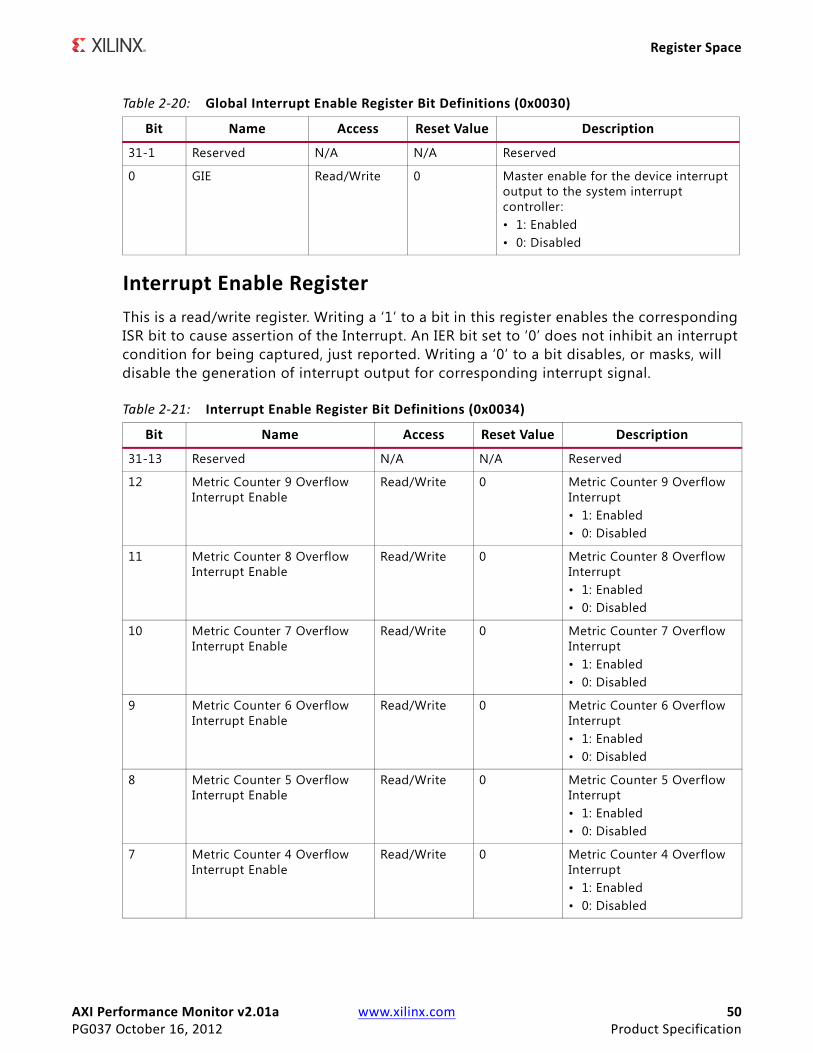
AXI Performance Monitor v2.01a www.xilinx.com 50PG037 October 16, 2012 Product Specification
Register Space
Interrupt Enable RegisterThis is a read/write register. Writing a ‘1’ to a bit in this register enables the corresponding ISR bit to cause assertion of the Interrupt. An IER bit set to ‘0’ does not inhibit an interrupt condition for being captured, just reported. Writing a ‘0’ to a bit disables, or masks, will disable the generation of interrupt output for corresponding interrupt signal.
Table 2-20: Global Interrupt Enable Register Bit Definitions (0x0030)
Bit Name Access Reset Value Description
31-1 Reserved N/A N/A Reserved
0 GIE Read/Write 0 Master enable for the device interrupt output to the system interrupt controller:• 1: Enabled• 0: Disabled
Table 2-21: Interrupt Enable Register Bit Definitions (0x0034)
Bit Name Access Reset Value Description
31-13 Reserved N/A N/A Reserved
12 Metric Counter 9 Overflow Interrupt Enable
Read/Write 0 Metric Counter 9 Overflow Interrupt • 1: Enabled• 0: Disabled
11 Metric Counter 8 Overflow Interrupt Enable
Read/Write 0 Metric Counter 8 Overflow Interrupt • 1: Enabled• 0: Disabled
10 Metric Counter 7 Overflow Interrupt Enable
Read/Write 0 Metric Counter 7 Overflow Interrupt • 1: Enabled• 0: Disabled
9 Metric Counter 6 Overflow Interrupt Enable
Read/Write 0 Metric Counter 6 Overflow Interrupt • 1: Enabled• 0: Disabled
8 Metric Counter 5 Overflow Interrupt Enable
Read/Write 0 Metric Counter 5 Overflow Interrupt • 1: Enabled• 0: Disabled
7 Metric Counter 4 Overflow Interrupt Enable
Read/Write 0 Metric Counter 4 Overflow Interrupt • 1: Enabled• 0: Disabled
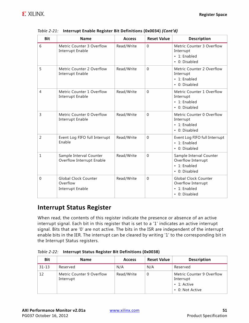
AXI Performance Monitor v2.01a www.xilinx.com 51PG037 October 16, 2012 Product Specification
Register Space
Interrupt Status RegisterWhen read, the contents of this register indicate the presence or absence of an active interrupt signal. Each bit in this register that is set to a ‘1’ indicates an active interrupt signal. Bits that are ‘0’ are not active. The bits in the ISR are independent of the interrupt enable bits in the IER. The interrupt can be cleared by writing '1' to the corresponding bit in the Interrupt Status registers.
6 Metric Counter 3 Overflow Interrupt Enable
Read/Write 0 Metric Counter 3 Overflow Interrupt • 1: Enabled• 0: Disabled
5 Metric Counter 2 Overflow Interrupt Enable
Read/Write 0 Metric Counter 2 Overflow Interrupt • 1: Enabled• 0: Disabled
4 Metric Counter 1 Overflow Interrupt Enable
Read/Write 0 Metric Counter 1 Overflow Interrupt • 1: Enabled• 0: Disabled
3 Metric Counter 0 Overflow Interrupt Enable
Read/Write 0 Metric Counter 0 Overflow Interrupt • 1: Enabled• 0: Disabled
2 Event Log FIFO full Interrupt Enable
Read/Write 0 Event Log FIFO full Interrupt • 1: Enabled• 0: Disabled
1 Sample Interval Counter Overflow Interrupt Enable
Read/Write 0 Sample Interval Counter Overflow Interrupt• 1: Enabled• 0: Disabled
0 Global Clock Counter OverflowInterrupt Enable
Read/Write 0 Global Clock Counter Overflow Interrupt• 1: Enabled• 0: Disabled
Table 2-22: Interrupt Status Register Bit Definitions (0x0038)
Bit Name Access Reset Value Description
31-13 Reserved N/A N/A Reserved
12 Metric Counter 9 Overflow Interrupt
Read/Write 0 Metric Counter 9 Overflow Interrupt • 1: Active• 0: Not Active
Table 2-21: Interrupt Enable Register Bit Definitions (0x0034) (Cont’d)
Bit Name Access Reset Value Description
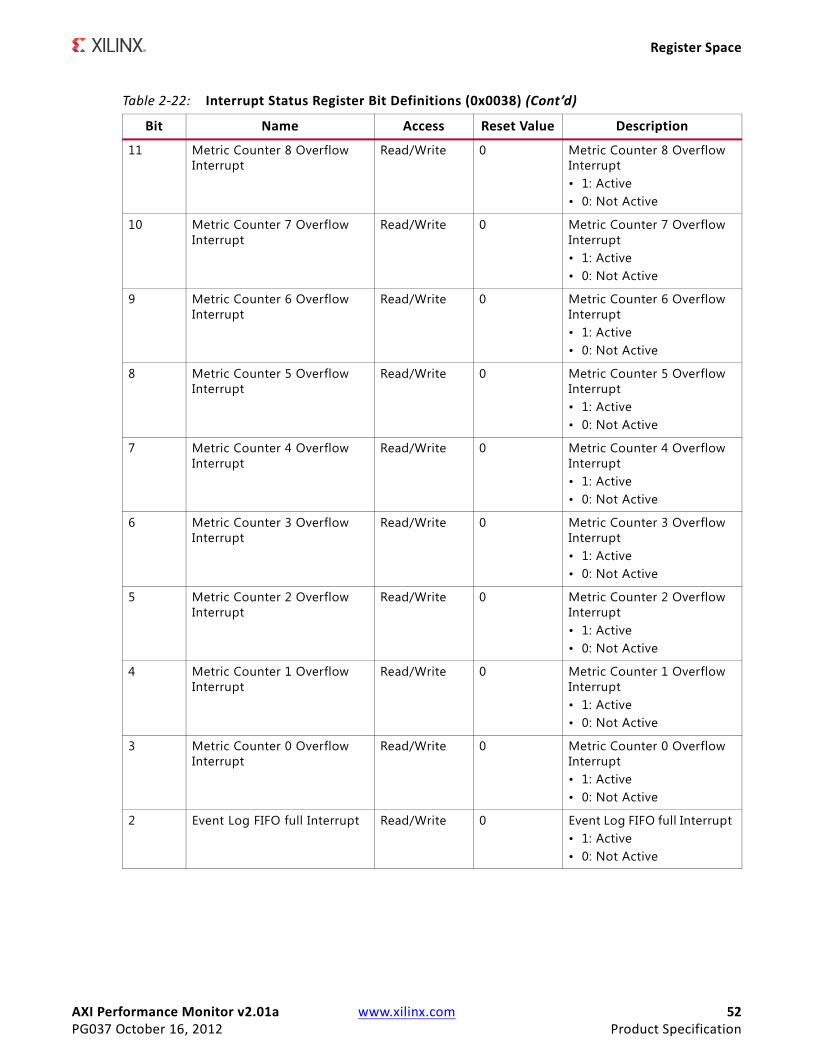
AXI Performance Monitor v2.01a www.xilinx.com 52PG037 October 16, 2012 Product Specification
Register Space
11 Metric Counter 8 Overflow Interrupt
Read/Write 0 Metric Counter 8 Overflow Interrupt • 1: Active• 0: Not Active
10 Metric Counter 7 Overflow Interrupt
Read/Write 0 Metric Counter 7 Overflow Interrupt • 1: Active• 0: Not Active
9 Metric Counter 6 Overflow Interrupt
Read/Write 0 Metric Counter 6 Overflow Interrupt • 1: Active• 0: Not Active
8 Metric Counter 5 Overflow Interrupt
Read/Write 0 Metric Counter 5 Overflow Interrupt • 1: Active• 0: Not Active
7 Metric Counter 4 Overflow Interrupt
Read/Write 0 Metric Counter 4 Overflow Interrupt • 1: Active• 0: Not Active
6 Metric Counter 3 Overflow Interrupt
Read/Write 0 Metric Counter 3 Overflow Interrupt • 1: Active• 0: Not Active
5 Metric Counter 2 Overflow Interrupt
Read/Write 0 Metric Counter 2 Overflow Interrupt • 1: Active• 0: Not Active
4 Metric Counter 1 Overflow Interrupt
Read/Write 0 Metric Counter 1 Overflow Interrupt • 1: Active• 0: Not Active
3 Metric Counter 0 Overflow Interrupt
Read/Write 0 Metric Counter 0 Overflow Interrupt • 1: Active• 0: Not Active
2 Event Log FIFO full Interrupt Read/Write 0 Event Log FIFO full Interrupt • 1: Active• 0: Not Active
Table 2-22: Interrupt Status Register Bit Definitions (0x0038) (Cont’d)
Bit Name Access Reset Value Description
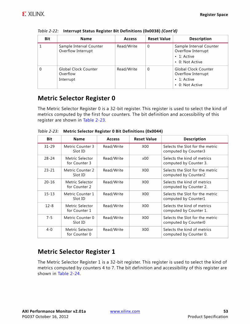
AXI Performance Monitor v2.01a www.xilinx.com 53PG037 October 16, 2012 Product Specification
Register Space
Metric Selector Register 0The Metric Selector Register 0 is a 32-bit register. This register is used to select the kind of metrics computed by the first four counters. The bit definition and accessibility of this register are shown in Table 2-23.
Metric Selector Register 1The Metric Selector Register 1 is a 32-bit register. This register is used to select the kind of metrics computed by counters 4 to 7. The bit definition and accessibility of this register are shown in Table 2-24.
1 Sample Interval Counter Overflow Interrupt
Read/Write 0 Sample Interval Counter Overflow Interrupt• 1: Active• 0: Not Active
0 Global Clock Counter OverflowInterrupt
Read/Write 0 Global Clock Counter Overflow Interrupt• 1: Active• 0: Not Active
Table 2-23: Metric Selector Register 0 Bit Definitions (0x0044)
Bit Name Access Reset Value Description
31-29 Metric Counter 3 Slot ID
Read/Write X00 Selects the Slot for the metric computed by Counter3
28-24 Metric Selector for Counter 3
Read/Write x00 Selects the kind of metrics computed by Counter 3.
23-21 Metric Counter 2 Slot ID
Read/Write X00 Selects the Slot for the metric computed by Counter2
20-16 Metric Selector for Counter 2
Read/Write X00 Selects the kind of metrics computed by Counter 2.
15-13 Metric Counter 1 Slot ID
Read/Write X00 Selects the Slot for the metric computed by Counter1
12-8 Metric Selector for Counter 1
Read/Write X00 Selects the kind of metrics computed by Counter 1.
7-5 Metric Counter 0 Slot ID
Read/Write X00 Selects the Slot for the metric computed by Counter0
4-0 Metric Selector for Counter 0
Read/Write X00 Selects the kind of metrics computed by Counter 0.
Table 2-22: Interrupt Status Register Bit Definitions (0x0038) (Cont’d)
Bit Name Access Reset Value Description
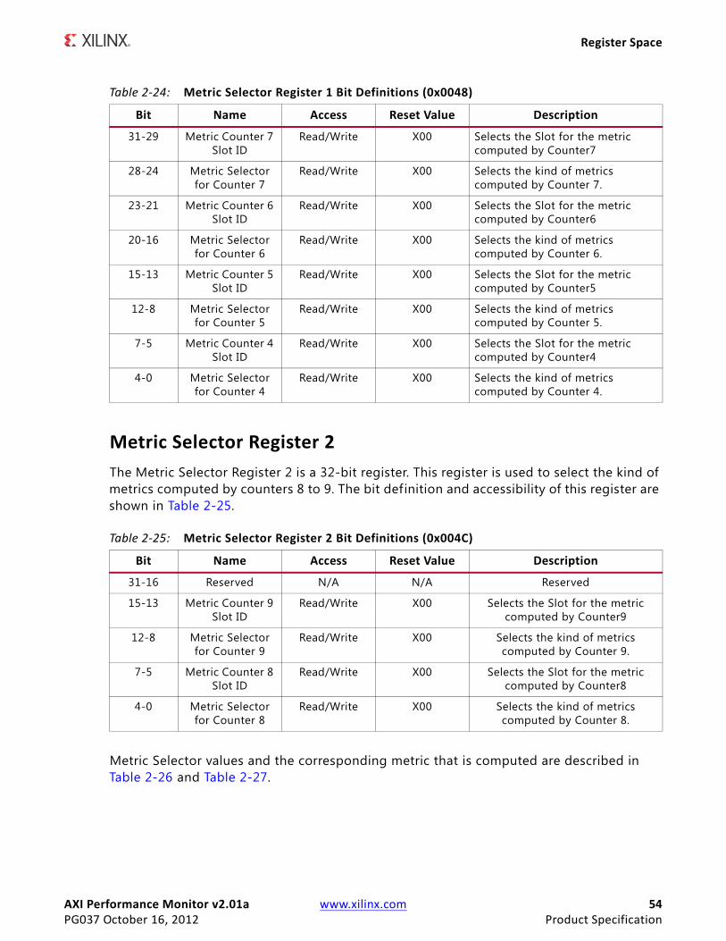
AXI Performance Monitor v2.01a www.xilinx.com 54PG037 October 16, 2012 Product Specification
Register Space
Metric Selector Register 2The Metric Selector Register 2 is a 32-bit register. This register is used to select the kind of metrics computed by counters 8 to 9. The bit definition and accessibility of this register are shown in Table 2-25.
Metric Selector values and the corresponding metric that is computed are described in Table 2-26 and Table 2-27.
Table 2-24: Metric Selector Register 1 Bit Definitions (0x0048)
Bit Name Access Reset Value Description
31-29 Metric Counter 7 Slot ID
Read/Write X00 Selects the Slot for the metric computed by Counter7
28-24 Metric Selector for Counter 7
Read/Write X00 Selects the kind of metrics computed by Counter 7.
23-21 Metric Counter 6 Slot ID
Read/Write X00 Selects the Slot for the metric computed by Counter6
20-16 Metric Selector for Counter 6
Read/Write X00 Selects the kind of metrics computed by Counter 6.
15-13 Metric Counter 5 Slot ID
Read/Write X00 Selects the Slot for the metric computed by Counter5
12-8 Metric Selector for Counter 5
Read/Write X00 Selects the kind of metrics computed by Counter 5.
7-5 Metric Counter 4 Slot ID
Read/Write X00 Selects the Slot for the metric computed by Counter4
4-0 Metric Selector for Counter 4
Read/Write X00 Selects the kind of metrics computed by Counter 4.
Table 2-25: Metric Selector Register 2 Bit Definitions (0x004C)
Bit Name Access Reset Value Description
31-16 Reserved N/A N/A Reserved
15-13 Metric Counter 9 Slot ID
Read/Write X00 Selects the Slot for the metric computed by Counter9
12-8 Metric Selector for Counter 9
Read/Write X00 Selects the kind of metrics computed by Counter 9.
7-5 Metric Counter 8 Slot ID
Read/Write X00 Selects the Slot for the metric computed by Counter8
4-0 Metric Selector for Counter 8
Read/Write X00 Selects the kind of metrics computed by Counter 8.
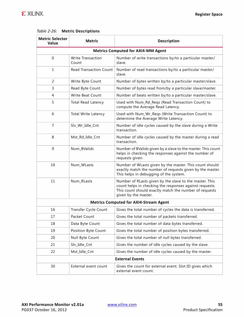
AXI Performance Monitor v2.01a www.xilinx.com 55PG037 October 16, 2012 Product Specification
Register Space
Table 2-26: Metric Descriptions
Metric Selector Value Metric Description
Metrics Computed for AXI4-MM Agent
0 Write Transaction Count
Number of write transactions by/to a particular master/slave.
1 Read Transaction Count Number of read transactions by/to a particular master/slave.
2 Write Byte Count Number of bytes written by/to a particular master/slave.
3 Read Byte Count Number of bytes read from/by a particular slave/master.
4 Write Beat Count Number of beats written by/to a particular master/slave.
5 Total Read Latency Used with Num_Rd_Reqs (Read Transaction Count) to compute the Average Read Latency.
6 Total Write Latency Used with Num_Wr_Reqs (Write Transaction Count) to determine the Average Write Latency.
7 Slv_Wr_Idle_Cnt Number of idle cycles caused by the slave during a Write transaction.
8 Mst_Rd_Idle_Cnt Number of idle cycles caused by the master during a read transaction.
9 Num_BValids Number of BValids given by a slave to the master. This count helps in checking the responses against the number of requests given.
10 Num_WLasts Number of WLasts given by the master. This count should exactly match the number of requests given by the master. This helps in debugging of the system.
11 Num_RLasts Number of RLasts given by the slave to the master. This count helps in checking the responses against requests. This count should exactly match the number of requests given by the master.
Metrics Computed for AXI4-Stream Agent
16 Transfer Cycle Count Gives the total number of cycles the data is transferred.
17 Packet Count Gives the total number of packets transferred.
18 Data Byte Count Gives the total number of data bytes transferred.
19 Position Byte Count Gives the total number of position bytes transferred.
20 Null Byte Count Gives the total number of null bytes transferred.
21 Slv_Idle_Cnt Gives the number of idle cycles caused by the slave.
22 Mst_Idle_Cnt Gives the number of idle cycles caused by the master.
External Events
30 External event count Gives the count for external event. Slot ID gives which external event count.
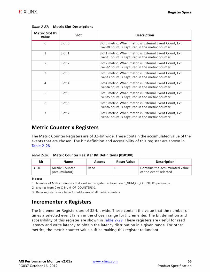
AXI Performance Monitor v2.01a www.xilinx.com 56PG037 October 16, 2012 Product Specification
Register Space
Metric Counter x RegistersThe Metric Counter Registers are of 32-bit wide. These contain the accumulated value of the events that are chosen. The bit definition and accessibility of this register are shown in Table 2-28.
Incrementer x RegistersThe Incrementer Registers are of 32-bit wide. These contain the value that the number of times a selected event fallen in the chosen range for Incrementer. The bit definition and accessibility of this register are shown in Table 2-29. These registers are useful for read latency and write latency to obtain the latency distribution in a given range. For other metrics, the metric counter value suffice making this register redundant.
Table 2-27: Metric Slot Descriptions
Metric Slot ID Value Slot Description
0 Slot 0 Slot0 metric. When metric is External Event Count, Ext Event0 count is captured in the metric counter.
1 Slot 1 Slot1 metric. When metric is External Event Count, Ext Event1 count is captured in the metric counter.
2 Slot 2 Slot2 metric. When metric is External Event Count, Ext Event2 count is captured in the metric counter.
3 Slot 3 Slot3 metric. When metric is External Event Count, Ext Event3 count is captured in the metric counter.
4 Slot 4 Slot4 metric. When metric is External Event Count, Ext Event4 count is captured in the metric counter.
5 Slot 5 Slot5 metric. When metric is External Event Count, Ext Event5 count is captured in the metric counter.
6 Slot 6 Slot6 metric. When metric is External Event Count, Ext Event6 count is captured in the metric counter.
7 Slot 7 Slot7 metric. When metric is External Event Count, Ext Event7 count is captured in the metric counter
Table 2-28: Metric Counter Register Bit Definitions (0x0100)
Bit Name Access Reset Value Description
31-0 Metric Counter (Accumulator)
Read 0 Contains the accumulated value of the event selected
Notes: 1. Number of Metric Counters that exist in the system is based on C_NUM_OF_COUNTERS parameter.2. x varies from 0 to C_NUM_OF_COUNTERS-13. Refer register space table for addresses of all metric counters

AXI Performance Monitor v2.01a www.xilinx.com 57PG037 October 16, 2012 Product Specification
Register Space
Range Register xThe Range Registers are of 32-bit wide. These registers help in incrementing the incrementer when the selected event falls in the range specif ied here. The bit definition and accessibility of this register are shown in Table 2-30.
Sampled Metric Counter x RegistersThe Metric Counters are captured into the Sampled Metric Counter registers when there is a capture event. The capture event can be an external event passed to the core or an overflow event of the sample interval counter. These registers are in AXI clock domain. The bit definition and accessibility of this register are shown in Table 2-31.
Table 2-29: Incrementer Register Bit Definitions (0x0104)
Bit Name Access Reset Value Description
31-0 Incrementer Read 0 Contains the value of the Incrementer
Notes: 1. Number of Incrementers that exist in the system is based on C_NUM_OF_COUNTERS parameter.2. x varies from 0 to C_NUM_OF_COUNTERS-13. Refer register space table for addresses of all Incrementer Registers
Table 2-30: Range Register Bit Definitions (0x0108)
Bit Name Access Reset Value Description
31-16 Range HIGH Read / Write 0x00 Contains the HIGHER limit of a range
15-0 Range LOW Read / Write 0x00 Contains the LOWER limit of a range
Notes: 1. Number of Range Registers that exist in the system is based on C_NUM_OF_COUNTERS parameter.2. x varies from 0 to C_NUM_OF_COUNTERS-13. Refer register space table for addresses of all Range Registers
Table 2-31: Sampled Metric Counter Register Bit Definitions (0x0200)
Bit Name Access Reset Value Description
31-0 Sampled Metric Counter (Accumulator)
Read 0 Contains the sampled Metric Counter value
Notes: 1. Number of Sampled Metric Counters that exist in the system is based on C_NUM_OF_COUNTERS parameter.2. x varies from 0 to C_NUM_OF_COUNTERS-13. Refer register space table for addresses of all sampled metric counters
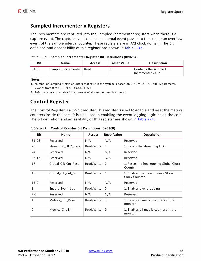
AXI Performance Monitor v2.01a www.xilinx.com 58PG037 October 16, 2012 Product Specification
Register Space
Sampled Incrementer x RegistersThe Incrementers are captured into the Sampled Incrementer registers when there is a capture event. The capture event can be an external event passed to the core or an overflow event of the sample interval counter. These registers are in AXI clock domain. The bit definition and accessibility of this register are shown in Table 2-32.
Control RegisterThe Control Register is a 32-bit register. This register is used to enable and reset the metrics counters inside the core. It is also used in enabling the event logging logic inside the core. The bit definition and accessibility of this register are shown in Table 2-33.
Table 2-32: Sampled Incrementer Register Bit Definitions (0x0204)
Bit Name Access Reset Value Description
31-0 Sampled Incrementer Read 0 Contains the sampled Incrementer value
Notes: 1. Number of Sampled Metric Counters that exist in the system is based on C_NUM_OF_COUNTERS parameter.2. x varies from 0 to C_NUM_OF_COUNTERS-13. Refer register space table for addresses of all sampled metric counters
Table 2-33: Control Register Bit Definitions (0x0300)
Bit Name Access Reset Value Description
31-26 Reserved N/A N/A Reserved
25 Streaming_FIFO_Reset Read/Write 0 1: Resets the streaming FIFO
24 Reserved N/A N/A Reserved
23-18 Reserved N/A N/A Reserved
17 Global_Clk_Cnt_Reset Read/Write 0 1: Resets the free-running Global Clock Counter
16 Global_Clk_Cnt_En Read/Write 0 1: Enables the free-running Global Clock Counter
15-9 Reserved N/A N/A Reserved
8 Enable_Event_Log Read/Write 0 1: Enables event logging
7-2 Reserved N/A N/A Reserved
1 Metrics_Cnt_Reset Read/Write 0 1: Resets all metric counters in the monitor
0 Metrics_Cnt_En Read/Write 0 1: Enables all metric counters in the monitor

AXI Performance Monitor v2.01a www.xilinx.com 59PG037 October 16, 2012 Product Specification
Register Space
Flag Enable Control RegisterThe Flag Enable Control Register is a 32-bit register. This register is used to enable the events that are used to log the data into streaming FIFO. The bit definition and accessibility of this register are shown in Table 2-34.
Software-Written Data RegisterThe Software-Written Data Register is a 32-bit register. This register value is written into the streaming FIFO upon write to this register. The bit definition and accessibility of this register are shown in Table 2-35.
Table 2-34: Flag Enable Control Register Bit Definitions (0x0400)
Bit Name Access Reset Value Description
31-20 Reserved N/A N/A Reserved
19 Enable External Event Start Flag
Read/Write 0 1: Enables event logging on Event start signal
18 Enable External Event Stop Flag
Read/Write 0 1: Enables event logging on Event stop signal
17 Enable External Event Flag
Read/Write 0 1: Enables event logging on Event signal
16 Enable Software-written data Flag
Read/Write 0 1: Enables event logging on write to Software-written data register
15-7 Reserved N/A N/A Reserved
6 Enable Last Read Flag Read/Write 0 1: Enables event logging on last read of a transaction
5 Enable First Read Flag
Read/Write 0 1: Enables event logging on f irst read of a transaction
4 Enable Read Addr Flag
Read/Write 0 1: Enables event logging on read address latch
3 Enable Response Flag Read/Write 0 1: Enables event logging on response of a transaction
2 Enable Last Write Flag
Read/Write 0 1: Enables event logging on last write of a transaction
1 Enable First Write Flag
Read/Write 0 1: Enables event logging on first write of a transaction
0 Enable Write Addr Flag
Read/Write 0 1: Enables event logging on write address latch
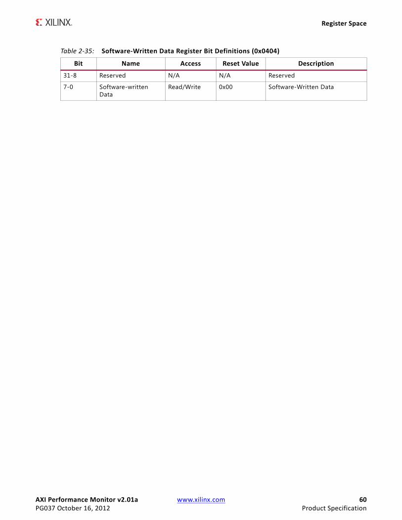
AXI Performance Monitor v2.01a www.xilinx.com 60PG037 October 16, 2012 Product Specification
Register Space
Table 2-35: Software-Written Data Register Bit Definitions (0x0404)
Bit Name Access Reset Value Description
31-8 Reserved N/A N/A Reserved
7-0 Software-written Data
Read/Write 0x00 Software-Written Data
AXI Performance Monitor v2.01a www.xilinx.com 61PG037 October 16, 2012
Chapter 3
Designing with the CoreThis chapter includes guidelines and additional information to make designing with the core easier.
General Design GuidelinesThe following steps are recommended for all designs using Event Count logic of the Performance Monitor:
1. Instantiate the Performance Monitor core in the EDK system. See Figure 3-1.
2. Configure the core based on the agents connected to the monitor slots.
3. Verify CORE_ACLK is the fastest clock in the design.
4. Program the configuration registers.
5. Write to Metric Selector Registers with the metric type and targeted agent.
6. Enable the metrics and global counter (Control register).
7. Read Metric Counters/Incrementers/Sampled Metric Counters/Sampled Incrementers/Global Clock Counter based on the requirement.
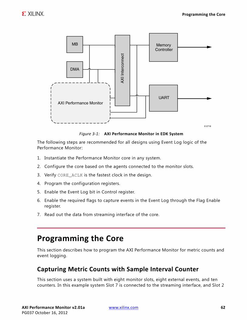
AXI Performance Monitor v2.01a www.xilinx.com 62PG037 October 16, 2012
Programming the Core
The following steps are recommended for all designs using Event Log logic of the Performance Monitor:
1. Instantiate the Performance Monitor core in any system.
2. Configure the core based on the agents connected to the monitor slots.
3. Verify CORE_ACLK is the fastest clock in the design.
4. Program the configuration registers.
5. Enable the Event Log bit in Control register.
6. Enable the required flags to capture events in the Event Log through the Flag Enable register.
7. Read out the data from streaming interface of the core.
Programming the CoreThis section describes how to program the AXI Performance Monitor for metric counts and event logging.
Capturing Metric Counts with Sample Interval CounterThis section uses a system built with eight monitor slots, eight external events, and ten counters. In this example system Slot 7 is connected to the streaming interface, and Slot 2
X-Ref Target - Figure 3-1
Figure 3-1: AXI Performance Monitor in EDK System

AXI Performance Monitor v2.01a www.xilinx.com 63PG037 October 16, 2012
Programming the Core
is connected to the memory map interface. In this use case, the steps to capture the metric counts with the sample interval counter are as follows:
1. Reset the global clock counter and metric counters by writing 0x0020002 into the Control register (0x300).
2. Configure the metric selection registers (0x44, 0x48, 0x4C) for the required slot metrics. The following list details the configuration that should be used with each metric selection register:
° Write Metric Selection Register 0 (0x44) with 0xF6F1F2F0
- Metric Counter 0: Slot 7 Transfer Cycle count
- Metric Counter 1: Slot 7 Data Byte count
- Metric Counter 2: Slot 7 Packet count
- Metric Counter 3: Slot 7 Master Idle count
° Write Metric Selection Register 1 (0x48) with 0x26222120
- Metric Counter 4: Slot 2 Write Transaction count
- Metric Counter 5: Slot 2 Read Transaction count
- Metric Counter 6: Slot 2 Write Byte count
- Metric Counter 7: Slot 2 Total Write latency
° Write Metric Selection Register 2 (0x4C) with 0x00005E1E
- Metric Counter 8: External Event 0 count
- Metric Counter 9: External Event 2 count
3. Enable Global Interrupt (0x30) with 0x00000001.
4. Enable Sample Interval Counter Overflow Interrupt (0x34) with 0x00000002.
5. Write the load value based on requirements in the Sample Interval Register (0x24) with 0x00001000 (4096 clocks).
6. Set the Load bit in the Sample Interval Control Register (0x28), that is 0x00000002.
7. Enable the Sample Interval Counter. Write 0x00000001 in the Sample Interval Control Register (0x28).
8. Enable Metric Counters. If required, enable the global clock counters by writing 0x00100001 in control register(0x300).
The Performance Monitor configuration is complete at this point, and the relevant slot transactions are now active (Slot 7, Slot 1, External Event 0 and External Event 2 for this example).
9. Wait for the Sample Interval Counter Overflow Interrupt (0x2 in 0x38), and then disable the sampled metric counters by writing 0x0000000 in 0x28.
AXI Performance Monitor v2.01a www.xilinx.com 64PG037 October 16, 2012
Programming the Core
10. Read the sampled metric counters (0x200, 0x210 and so on up to 0x290) to capture the configured metrics for a known period (4096 core clocks in this example).
Metric Counts for DMA/Memory TransfersFollow these steps to obtain the metric counts for DMA/Memory transfers:
1. Reset the global clock counter and metric counters by writing 0x0020002 into the Control Register (0x300).
2. Configure the metric selection registers (0x44, 0x48, 0x4C) for the required slot metrics.
3. Enable the metric counters by writing 0x00000001 in the Control Register(0x300).
4. Start DMA/Memory transfers.
5. After the transfers are complete, read the metric counters (0x100, 0x110 and so on up to 0x190) to get the configured metrics.
Runtimes for Applications and Event OccurrencesTo obtain runtimes for applications and event occurrences, f irst, the global clock counter width must be set to either 32 or 64 based on requirement. After the appropriate width configuration for the global clock counter has been set, follow these steps:
1. Reset the global clock counter by writing 0x0020000 into the Control Register (0x300).
2. Enable the global clock counter by writing 0x0010000 into the Control Register (0x300).
3. Run the application.
4. Read the 32 or 64-bit global clock counter value (0x4, 0x0) at the end of the application or at a specific event in the application to get the runtime of application.
Write and Read Latency Distribution of Monitor Slot for Five RangesAssuming the core is configured to have a single monitor slot (C_NUM_MONITOR_SLOTS =1) and 10 metric counters (C_NUM_OF_COUNTERS = 10), follow these steps to obtain the write and read latency distribution:
1. Reset the metric counters by writing 0x0000002 into the Control Register (0x300).
Configure the metric selection registers (0x44, 0x48, 0x4C) for the read and write latency of slot 0. Configure the metric counters 0 to 4 for read latency and metric counters 5 to 9 for write latency.
° Write Metric Selection Register 0 (0x44) with 0x05050505
° Write Metric Selection Register 1 (0x48) with 0x06060605
AXI Performance Monitor v2.01a www.xilinx.com 65PG037 October 16, 2012
Programming the Core
° Write Metric Selection Register 2 (0x4C) with 0x00000606
2. Configure the range registers with low and high values.
° Range registers for read latencies:
- Write Range Register 0 (0x108) with 0x140000 (0 to20)
- Write Range Register 1 (0x118) with 0x280015 (21 to 40)
- Write Range Register 2 (0x128) with 0x3C0029 (41 to 60)
- Write Range Register 3 (0x138) with 0x50003D (61 to 80)
- Write Range Register 4 (0x148) with 0x640051 (81 to 100)
° Range registers for write latencies:
- Write Range Register 0 (0x158) with 0x140000 (0 to20)
- Write Range Register 1(0x168) with 0x280015 (21 to 40)
- Write Range Register 2 (0x178) with 0x3C0029 (41 to 60)
- Write Range Register 3 (0x188) with 0x50003D (61 to 80)
- Write Range Register 4 (0x198) with 0x640051 (81 to 100)
3. Enable Metric Counters by writing 0x00000001 in the Control Register (0x300).
4. Slot 0 transactions can be started to capture read and write latencies.
5. After the Slot 0 transactions, read the incrementers (0x104, 0x114 and on up to 0x194) for the read and write latencies distribution in the given ranges.
By following this use case to load and enable sample interval counters, it is possible to get the data in sampled incrementers (0x204, 0x214 and on up to 0x294) after the 0x0024 clocks which are loaded in the Sample Interval register.
Event Log on First Write, First Read, Software-Written Data and External Event FlagsThis use case assumes the C_ENABLE_EVENT_LOG parameter is '1' and the other event log parameters (C_FIFO_AXIS_DEPTH, C_FIFO_AXIS_TDATA_WIDTH, C_FIFO_AXIS_ID_WIDTH, C_FIFO_AXIS_SYNC, C_SHOW_AXI_IDS, C_SHOW_AXI_LEN, C_SHOW_AXIS_TID, C_SHOW_AXIS_TDEST, and C_SHOW_AXIS_TUSER) are set properly. The steps to capture the event log on f irst write, f irst read, software-written data and external event flags is:
1. Reset the Streaming FIFO by writing 0x2000000 into the Control Register (0x300).
2. Enable the flags that are required to capture events in the event log by writing to the Flag Enable Register (0x400). For example, to enable First write, First Read, External Event and Software-Written Data flags, write 0x30022 in to the Flag Enable Register.
3. Write to the Software-Written Data Register with the data required to log.
AXI Performance Monitor v2.01a www.xilinx.com 66PG037 October 16, 2012
Clocking
4. Enable the external event log bit in the Control Register (write 0x800 in 0x300).
5. Offload the log data through the Streaming Interface.
ClockingCORE_ACLK should be the fastest clock among all the clocks connected to the AXI Performance Monitor.
ResetsAll external resets are Active Low except RESET_EVENT which resets the sampled metric counters.
AXI Performance Monitor v2.01a www.xilinx.com 67PG037 October 16, 2012
Chapter 4
Customizing and Generating the CoreThe AXI Performance Monitor can be found in Embedded_Processing\Debug & Verification in the Vivado IP Catalog.
To access the AXI Performance Monitor, do the following:
1. Open an existing project or create a new project in Vivado.
2. Open the IP catalog and navigate to any of the above taxonomies.
3. Double-click on AXI Performance Monitor to bring up the AXI Perf Mon GUI.
GUIThe AXI Performance Monitor GUI contains one screen (Figure 4-1) that provides information about the core, allows configuration, and generates the core.
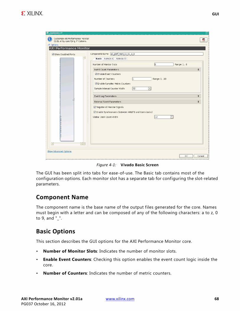
AXI Performance Monitor v2.01a www.xilinx.com 68PG037 October 16, 2012
GUI
The GUI has been split into tabs for ease-of-use. The Basic tab contains most of the configuration options. Each monitor slot has a separate tab for configuring the slot-related parameters.
Component NameThe component name is the base name of the output f iles generated for the core. Names must begin with a letter and can be composed of any of the following characters: a to z, 0 to 9, and "_".
Basic OptionsThis section describes the GUI options for the AXI Performance Monitor core.
• Number of Monitor Slots: Indicates the number of monitor slots.
• Enable Event Counters: Checking this option enables the event count logic inside the core.
• Number of Counters: Indicates the number of metric counters.
X-Ref Target - Figure 4-1
Figure 4-1: Vivado Basic Screen
AXI Performance Monitor v2.01a www.xilinx.com 69PG037 October 16, 2012
GUI
• Enable Sampled Metric Counters: Checking this option enables the sampled metric counters inside the core.
• Sample Interval Counter Width: Indicates the width of Sample Interval Counter. The value can be 32 or 64.
• Enable Event Log: Checking this option enables the event log logic inside the core.
• Streaming Interface TID Width: Indicates the TID width of the Streaming Interface.
• Streaming Interface TDATA Width: Indicates the TDATA width of the Streaming Interface.
• Streaming FIFO Depth: Indicates the depth of the Streaming FIFO.
• Enable FIFO for Event 0: Checking this option enables FIFO for synchronizing external event 0 signals to the core clock domain.
• Enable FIFO for Event 1: Checking this option enables FIFO for synchronizing external event 1 signals to the core clock domain.
• Register All Monitor Signals: Checking this option registers all monitor signals at the interface and as a result improves timing.
• Enable Synchronizers (between AXI4-LITE and Core Clocks): Checking this option enables synchronizers between the AXI4-LITE interface and the core clock domains.
• Global Clock Counter Width: Indicates the width of the Global Clock Counter. The value can be 32 or 64.
• Slot Options: This section describes the options that affect the monitor slot in the AXI Performance Monitor core.
• AXI Protocol: Indicates if the connected agent to the monitor slot is AXI4 MM or AXI4-Stream.
• ID Width: Indicates the ID width of the AXI4 MM slot.
• DATA Width: Indicates the DATA width of the AXI4 MM slot.
• Address Width: Indicates the Address width of the AXI4 MM slot.
• TUSER Width: Indicates the TUSER width of the AXI4-Stream slot.
• TDEST Width: Indicates the TDEST width of the AXI4-Stream slot.
• TID Width: Indicates the TID width of the AXI4-Stream slot.
• TDATA Width: Indicates the TDATA width of the AXI4-Stream slot.
• Enable FIFO: Checking this option enables FIFO for synchronizing monitor slot signals to the core clock domain.

AXI Performance Monitor v2.01a www.xilinx.com 70PG037 October 16, 2012
Chapter 5
Constraining the CoreThe following XDC constraints are added in core-level XDC file.
set clk_domain_a [get_clocks -of_objects [get_ports S_AXI_ACLK]]set clk_domain_b [get_clocks -of_objects [get_ports CORE_ACLK]]set_false_path -from [all_registers -clock $clk_domain_a] -to [all_registers -clock $clk_domain_b]set_false_path -from [all_registers -clock $clk_domain_b] -to [all_registers -clock $clk_domain_a]

AXI Performance Monitor v2.01a www.xilinx.com 71PG037 October 16, 2012
Appendix 6
MigratingFor details about migrating to the Vivado Design Suite, see UG911, Vivado Design Suite Migration Methodology Guide.
AXI Performance Monitor v2.01a www.xilinx.com 72PG037 October 16, 2012
Appendix A
Additional Resources
Xilinx ResourcesFor support resources such as Answers, Documentation, Downloads, and Forums, see the Xilinx Support website at:
www.xilinx.com/support.
For a glossary of technical terms used in Xilinx documentation, see:
www.xilinx.com/company/terms.htm.
For Vivado™ Design Suite documentation, see:
www.xilinx.com/cgi-bin/docs/rdoc?v=2012.3;t=vivado+docs
ReferencesThese documents provide supplemental material useful with this user guide:
• AXI4 AMBA AXI Protocol Version: 2.0 Specif ication
• AMBA AXI4-Stream Protocol Version: 1.0 Specif ication
Technical SupportXilinx provides technical support at www.xilinx.com/support for this LogiCORE™ IP product when used as described in the product documentation. Xilinx cannot guarantee timing, functionality, or support of product if implemented in devices that are not defined in the documentation, if customized beyond that allowed in the product documentation, or if changes are made to any section of the design labeled DO NOT MODIFY.

AXI Performance Monitor v2.01a www.xilinx.com 73PG037 October 16, 2012
Revision History
Revision HistoryThe following table shows the revision history for this document.
Notice of DisclaimerThe information disclosed to you hereunder (the “Materials”) is provided solely for the selection and use of Xilinx products. To the maximum extent permitted by applicable law: (1) Materials are made available “AS IS” and with all faults, Xilinx hereby DISCLAIMS ALL WARRANTIES AND CONDITIONS, EXPRESS, IMPLIED, OR STATUTORY, INCLUDING BUT NOT LIMITED TO WARRANTIES OF MERCHANTABILITY, NON-INFRINGEMENT, OR FITNESS FOR ANY PARTICULAR PURPOSE; and (2) Xilinx shall not be liable (whether in contract or tort, including negligence, or under any other theory of liability) for any loss or damage of any kind or nature related to, arising under, or in connection with, the Materials (including your use of the Materials), including for any direct, indirect, special, incidental, or consequential loss or damage (including loss of data, profits, goodwill, or any type of loss or damage suffered as a result of any action brought by a third party) even if such damage or loss was reasonably foreseeable or Xilinx had been advised of the possibility of the same. Xilinx assumes no obligation to correct any errors contained in the Materials or to notify you of updates to the Materials or to product specifications. You may not reproduce, modify, distribute, or publicly display the Materials without prior written consent. Certain products are subject to the terms and conditions of the Limited Warranties which can be viewed at http://www.xilinx.com/warranty.htm; IP cores may be subject to warranty and support terms contained in a license issued to you by Xilinx. Xilinx products are not designed or intended to be fail-safe or for use in any application requiring fail-safe performance; you assume sole risk and liability for use of Xilinx products in Critical Applications: http://www.xilinx.com/warranty.htm#critapps.© Copyright 2012 Xilinx, Inc. Xilinx, the Xilinx logo, Artix, ISE, Kintex, Spartan, Virtex, Vivado, Zynq, and other designated brands included herein are trademarks of Xilinx in the United States and other countries. All other trademarks are the property of their respective owners.
Date Version Revision
04/24/12 1.0 Initial Xilinx release.
05/22/12 1.1 Added Zynq-7000 support.
07/25/12 2.0 Added support for Vivado Design Suite. Added Event Log module and changed Event Count logic to be symmetric.
10/16/12 3.0 • Added External Event ports 2-7. • Added support for capturing any slot any metric at a time. • Event Log data is now captured based on the configuration to
reduce the width of log data.