Embed Size (px)
Citation preview

PERPUSTAKAAN UMP
ll III III III III II 1111 III III 0000092779
SEMI-RIGID BEAM TO LULUIVIIN UU1N1NtL11'J1N UlNiJ1R STATIC LOADING USING ABAQUS
NORLINA BINTI MUHAMAD NOR
Report submitted in partial fulfilment of the requirements for the award of the degree of
B. Eng (Hons.) Civil Engineering
Faculty of Civil Engineering and Earth Resources
UNIVERSITI MALAYSIA PAHANG
JUNE 2014
vi
ABSTRACT
The connection of beam to column is very essential especially to transfer and distributes the load as well as contributing in the rigidity of the overall structures. A proper design of connection between members is very important for a steel structure to perform its best in sustaining load. As the performance of computers were increasing widely and the availability of computer software, the use of the finite element method (FEM) possible in the current research and design activity. The objectives of this study are to model and simulate a 3D beam to column connection under static loading; to understand the behavior of the connection from moment-rotation graph and obtained the displacement, stiffness and rotation from the graph as well as to determine the types of failure in the connection. This paper presents thesemi-rigid beam to column connections using fasteners by using the ABAQUS finite element software code; since Finite Element Analysis (FEA) offers the feasibility to simulate the actual behavior of the joints beam to column connection at low costs and short period of time compared with the experimental tests A specimen using top and seat angle (SRC-3A) over 6 specimens in previous experimental by Khaled and Suswanto in 2013 was simulated and tested using static loadmg and the results obtained after the numerical simulation were compared with the experimental data in order to validate the model. Based on the result analysis of moment-rotation, it can be concluded that the connection lies in semi-rigid even though the stiffness of the model in simulation is high compared to experimental which impact to the largest moment of capacity. Lastly, the modes of failure for specimen SRO-A have been determined which are due to buckling at column flange and plate exactly as in experimental.
vii
ABSTRAK
Sambungan rasuk ke tiang adalah sangat penting terutama untuk memindahkan dan mengedarkan beban dan juga untuk menyumbang kepada ketegaran keseluruhan struktur. Satu reka bentuk yang betul sambungan antara struktur-struktur adalah amat penting bagi struktur keluli untuk melakukan yang terbaik dalam mengekalkan beban. Oleh kerana prestasi komputer telah meningkat secara meluas dan ketersediaan perisian komputer, penggunaan Kaedah Elemen Unsur. Terhingga (KEUT) memungkinkan aktiviti penyelidikan mi dan aktiviti reka bentuk. Objektif kajian mi adalah untuk memodel dan mensimulasi 3 dimensisambungan ke tiang di bawah beban statik; untuk memahami kelakuan sambungan daripada graf momen-putaran dan mendapat anjakan, kekakuan dan putaran daripada graf dan juga untuk menentukan jenis kegagalan dalam sambungan. Kajian mi membentangkan sambungan rasuk separa tegar untuk turus dengan pengikat dengan menggunakan unsur kod perisian ABAQUS; sejak .Analisis Unsur Terhingga (AUT) menawarkan kemungkinan untuk mensimulasikan kelakuan sebenar rasuk sendi untuk sambungan tiang pada kos yang rendah dan masa yang singkat berbanding dengan ujian eksperimen. Satu spesimen daripada 6 spesimen dalam eksperimén sebelum inidengan menggunakan sambungan sudutatas dan bawah (SRC-3A) telah simulasi dan diuji menggunakan pembebanan statik dan keputusan yang diperolehi selepas simulasi berangka telah dibandingkan dengan data uji kaji bagi mengesahkan model. Berdasarkan analisis keputusan graf momen-putaran, ia boleh disimpulkan bahawa sambungan terletak dalam sempadan separa tegar walaupun kekukuhan model dalam simulasi adalah lebth tinggl berbanding dengan ekspeiimen dimana ia memberi impak ke saat terbesar kapasiti Akhir sekali, kegagalan spesimen SRC3-A telah disebabkan oleh lengkokan di ruangan bebibir plat dan kegagalan yang diperoleh adalah seperti di dalam eksperimen.

TABLE OF CONTENTS
Page
SUPERVISOR'S DECLARATION
STUDENT'S DECLARATION
DEDICATION 1V
ACKNOWLEDGEMENTS v
ABSTRACT V1
ABSTRAK
TABLE OF CONTENTS viii
LIST OF TABLES x
LIST OF FIGURES xi
CHAPTER 1 INTRODUCTION
1.1 Background of-Study1
1.2 Problem Statement2
1.3 Objectives
1.4 Scope of Study
CHAPTER 2 LITERATURE REVIEW
2.1 Classification on Connection 5
2.2 General Type of Beam to Column Connection 8
2.2.1 Top and Seat Angle Connection 8 2.2.2 Double Web Angle Connection 9 2.2.3 Top-Seat Angle with Double Web Angle Connection 9
2.3 Loads on Structure 10
2.4 Behavior of Connection 12
2.4.1 Ductility 13 2.4.2 Stifthess 15 2.4.3 Modes of Failure 16
2.5 Finite Element Method 18
viii
ix
CHAPTER 3 RESEARCH METHODOLOGY
3.1 Introduction 19
3.2 Experimental Program Details 20
3.3 Simulation Program Details 20
3.3.1 Material Properties and Modeling 20
3.4 Simulation Procedure 23
3.4.1 Preprocessing 24 3.4.2 Analysis 29 3.4.3 Visualization 29
3.5 Moment Displacement and Moment Rotation Graph 30
CHAPTER 4 RESULTS AND DISCUSSION
4.1 Moment Displacement 32
4.2 Moment Rotation and Stiffness 32
4.3 Modes of Failure 34
4.4 Performance of the Connection 35
4.5 Factor Contribute to Dissimilarities 35
4.5.1 Type of meshing 36 4.5.2 Sliding of bolt 38 4.5.3 Mechanical properties 38 4.5.4 Contact interaction between surfaces 38
CHAPTER 5 CONCLUSION AND RECOMMENDATIONS
5.1 Conclusion 40
5.2 Recommendations 41
REFERENCES 42

x
LIST OF TABLES
Table No. Title Page
3.1 Structural steels and bolts used of the specimen 20
3.2 Material properties of the model 25
3.3 Increment size of the model 26
3.4 Number of mesh of the model 28
4.1 Summarization performance of the model 35
4.2 Surface interaction 39

xi
LIST OF FIGURES
Figure No. Title Page
2.1 Moment Diagrams for Uniform Loading 6
2.2 Minimum Natural Frequency for Beams of Uniform Mass 6
2.3 Classes of beam to column connection 7
2.4 Top and seat angle connection 8
2.5 Double web angle connection 9
2.6 Top-seat angle with double web angle connection 9
2.7 Connection moment-rotation curve 10
2.8 Monotonic and cyclic loading graph for load versus time 11
2.9 Rotational deformation of a connection 12
2.10 Stress-strain curve 13
2.11 A typical stress-strain curve for steel 14
2.12 A typical stress-strain curve for ductile material 14
2.13 Failure modes for semi-rigid connection 16
2.14 Deformation of seat angle 17
3.1 Abaqus software interface 19
3.2 Detail of beam to column specimen 21
3.3 Detail of top and seat angle connection 21
3.4 Abaqus part metnodology 22
3.5 Sequence module of Abaqus 22
3.6 Abaqus module in context bar 23
3.7 Consistent units (Abaqus Manual 6.10) 23
3.8 Part created for the model 24
3.9 Assembled model of beam to column connection 26
3.10 Surface to surface contact interaction 27
3.11 Load and boundary condition applied at beam to column 27
connection
3.12 Meshing of beam to column connection 28
3.13 Job monitor in simulation analysis 29
3.14 Moment displacement graph of experimental 30

xii
3.15 Moment rotation graph of experimental 31
4.1 Moment Displacement Relationship Graph 33
4.2 Moment rotation relationship graph 33
4.3 Buckling at column flange 34
4.4 Buckling at plate 35
4.5 Stress distribution at beam to column connection 36
4.6 Fine meshing of beam to column connection 37
4.7 Coarse meshing of beam to column connection 37
4.8 Graph of comparison between type of meshing 37
CHAPTER 1
INTRODUCTION
1.1 BACKGROUND OF STUDY
The behavior Of steel bolted connections continually to be an issues in the steel
construction field. The rigidity of the structures could be one of the factors as the
structure is too rigid, there are no allowances for the structures to deform to an
allowable limit or to respond accordingly to loads particularly at the connection between
beam to the column. In practice, connections are usually assumed as either, rigid or
pinned while in reality, every connection that lies in between these two connections are
called semi-rigid or partially restrained connections.
Semi-rigid connections with angles connecting to the web and flanges of the
beam and to the column flange are more affordable and uncomplicated to assemble
when compared to other joint. Therefore, the use of semi-rigid connections using bolted
angles is justified as from previous study, rigid connections are seems to be more
expensive and difficult to assemble and this connections also do not have the enough
resistance and stiffness to resist the lateral loads.
Semi-rigidity is required in understanding the behavior of connections.
According to Demirtas in 2003, semi-rigidity could be used to reduce fixed end
moments in rigid connections consequence in an economic benefit. It can be applied to
simple connections to increase stiffness and serviceability. In addition, semi-rigidity
also can be used to obtain intermediate-strength in the connection. These apparent
advantages of semi-rigid connections over typical rigid and simple connections becomes
2
a disadvantage if the engineer is not provided with the right analysis and design tools
(Chen, Yoshiaki and Richard, 1996).
The design of semi-rigid steel frames depends on the joint characteristics, which
is the moment-rotation model. This work indicates a great number of experimental tests
which resulting a great cost of time and money. By starting from this view point, the
Finite Element (FE) method such as ABAQUS software which used in this study
represents an interesting alternative to predict the proper and relevant moment-rotation
model as well as to analyze the behavior of angle connections under various loading
conditions. However, much attention should be given to the selection of appropriate
element types, boundary conditions, and contact coefficients when using the finite
element method.
Besides that, by using finite element analysis, it can provide a better
understanding of the behavior of steel connections under static loads. It is important to
perfectly characterize the interaction of the various components of a steel connection
such as bolts and welds. For this, it is important to understand and sufficiently model
the contact interaction between the various interacting parts of the connection and to
correctly specify their constitutive properties.
1.2 PROBLEM STATEMENT
The connection beam to column is very essential especially to transfer and
distributes the load as well as to contribute to the rigidity of the overall structures. Thus
to respond to various of load, the connection should be allowed to be less rigid and
allowed for a degree of flexibility where semi-rigid connection offered the performance
as the connection is proposed to analyze as a spring element. The classification of the
connection is based on the stiffness from moment-rotation graph resulted from an
experimental setup as well as other result such as types of failure or the behavior under
the loading in which consumes a lot of time and costly where these were opted by most
Of the research such as Khaled and Suswanto in 2013. As the wide increasing
performance of computers and the availability of computer software, the cost and time
spent to analyze and design of semi-rigid steel connection between beam and column

3
can be reduced. In this study, an experimental setup of beam - column connections was
chosen from a study by Khaled and Suswanto (2013) to be modeled and simulate under
static loading to determine the behavior, stiffness and the types of failure through the
application of ABAQUS software.
1.3 OBJECTIVES
The overall research goal of this project is to determine the performance
characteristics of the beam to column connection in order to evaluate its suitability for
use in actual steel construction.
1. To model and simulate a 3 dimensional top and seat angle connection under
static loading.
2. To understand the behaviour of the connection from moment-rotation graph and
obtained the displacement, stiffness and rotation.
3. To determine the types of failure in the connection.
1.4 SCOPE OF STUDY
This study is focused with the study of structural response of a typical semi-rigid
beam to column connection. The data from previous experiments titled Experimental
Study, Stiffness of Semi-Rigid Beam-to-Column Connections Using Bolt and Angles
(Khaled and Suswanto, 2013) was calibrated In order to study the individual
contribution of them, 1 specimen over 6 specimens (in experimental) consist of beam to
column connection using top and seat angles (SRC3-A) was prepared to be simulated
and compared.
Finite element analysis (FEA) which has been widely used in engineering
industry to simulate the structures and load act on them; was used in this study. The FE
model was prepared for three dimensional (31)) simulations of FE code ABAQUS
software. Once the model have been verified, it was subjected to simulated concentrated
incremental load and the results obtained from this simulation will be used to analyze
the behavior of these connections under static loading. This 3D simulation will provide
needed performance characteristics of the connection and parameters where the result of
previous experimental testing have obtained stiffness, behavior of connections and
failure mode of structure.

CHAPTER 2
LITERATURE REVIEW
2.1 CLASSIFICATION ON CONNECTION
Beam to column connections can be classified according to their types of loads
transmit and the scale of those loads, types of members connected and whether they are
exposed or hidden. In general, the connections must transmit axial and shear forces and
bending and torsional moments There are many types of beam to column connections
and corresponding to their response variables..
Jones in 1980 stated the responses of connection can be classified according to
broad ranges of flexural behavior and also can be seen in Figure 2.1 and Figure 2.2
while classes of beam to column connection are shown in Figure 2.3.
1. Pinned connections (flexible).
- Pinned connection allows relative free rotation between the end of the
beam and colunrn and also able to carry the required end reaction.
2. Rigid connections (fixed)
- Rigid connection are those in which the rotation is reduced to a minimum
by the use of heavy connection details.
3. Semi-rigid connections
- Semi-rigid connections transmit bending moment with some degree of
rotation and provide a degree of end restraint somewhere between.
complete rigidity and complete flexibility.

IN
W w
Pin - Pin
Semi-rigid
Fixed-Fixed
Figure 2.1 : Moment Diagrams for Uniform Loading
Source: McGuire (1995)
fn I _22.4fi7i 27twL 27t \'wL
1-= v= 1 v1 Pin-Pin Semi-rigid Fixed-Fixed
Figure 2.2: Minimum Natural Frequency for Beams of Uniform Mass
Source McGuire (1995)
However, according to Kartal et al. in 2010, structural connections should be
named according to their moment-rotation curves which are usually derived by fitting
suitable curves to the experimental data.

Is
NO END MOMENT
7
LESS THA FIXED
END MOMENT
IS
FIXED END
.MOMENT
Ms
a. Flexible connection
b. Semi-rigid connection
C. Rigid connection
Figure 2.3: Classes of beam to column connection
Source : Jones (1980)

8
2.2 GENERAL TYPES OF BEAM TO COLUMN CONNECTION
In design and analysis of steel structures, the rigid assumption results in larger
joint stiffness relative to the beam and column stiffness, while the pinned connection
assumption results in smaller joint stiffness relative to the connection member stiffness.
Beam to column connections are classified according to the physical configuration and
the means by which beams and columns are connected. There are some types of
fastening connections of steel beam to column which are angles, plates, welds, and
bolts. From Khaled and Suswanto (2013) experimental study, top-seat angle and double
web angle were proposed but in present study, the type of connection is concerned on
bolts and angles which is top and seat angle connection as shown in Figure 2.6.
2.2.1 Top and seat angle connection
Based on AISC (1989), top angle is used to provide lateral support of the
compression beam flange while the seat angle is used to transfer only vertical reaction
of the beam to the column. It should not give a significant restraining moment at the end
of the beam. White (2003) stated that beam stresses due to shear and flexure are
transferred to the column through bolted brackets located at the top and bottom of the
beam flanges. However according to the experimental result, this connection can
transfer not only the vertical reaction but also some end moment of the beam to the
column.
Figure 2.4: Top and seat angle connection
Source: Chen, Yoshiaki and Richard (1996)

I o
2.2.2 Double web angle connection
A double web-angle connection consists of two angle either bolted or riveted to
both column and beam web. Although the connection rigidityof this type of connection
is stiffer than single web angle and single plate connection, ATSC (1989) consider this
type of connection as simple connection or shear connection.
Figure 2.5: Double web angle connection
Source: Chen, Yoshiaki and Richard (1996)
2.2.3 Top-seat angle with double web angle connection
This type of connection is the combination of top-seat angle and double web
angle connection. Double web angle connection is used to improve the connection
restraint characteristics and shear transfer of top and seat angle conncetion.
Figure 2.6: Top-seat angle with double web angle connection
Source : Vellasco et al. (2005)

Moment H
i114&d
10
The typical moment-rotation curve for behavior of variety type of connection of
semirigid can be represent in Figure 2.7.
Figure 2.7: Connection moment-rotation curve
Source : Jones (1980)
2.3 LOAD ON STRUCTURE
Loads usually are classified into two groups which are dead loads and live loads.
Dead loads are basically constant during the life of the structure and normally consist of
the weight of the structural elements. On the other hand, live loads usually are
otherwise. The magnitudes of these loads are not known with great accuracy and the
design values must depend on the intended use of the structure.
Basically, there are two types of load or forces that act on structures which are
static and dynamic load. Static load or monotonic load which focused in this study are
those that are gradually applied and remain in place for long time duration. The live
load acting on a structure considered as a static load because it usually varies gradually
in magnitude and position while cyclic load are those that are very much time dependent
and these either act for a small interval of time or quickly change in magnitude or
direction

cyclic loading monotonic loading
1)
E cj I.-
a-cl 0
I
According to Sandor in 2000, loading is assumed to be applied on the structure
in two different ways; monotonic and cyclic as shown in Figure 2.8. Monotonic loading
can be defined as the classical static loading that having the feature which are quasi-
static and its instensity is increasing in time. For the cyclic loading, it represent a
simplified seismic loading with repeated loading-unloading reversely. Cyclic loading's
intensity is high to cause significant plastic strain in the structure.
Figure 2.8 : Monotonic and cyclic loading graph for load versus time
Source: Sandor (2000)
There are certain number of experimental under monotonic loading. Elghazouli
(1996) have study the ductility of frames with semi-rigid connection while Elnashai,
Elghazouli, and Denesh in 1998 have conducted 8 model in experimental to investigate
the performance of steel frames with semi-rigid connections consists of top and seat and
web angles in order to compare with fully rigid alternatives.
Psycharis and Mouzakjs in 2012 have investigated on beam to column
Connection. Their research was focused on important design aspects and the effect of
several parameters on the shear resistance of the connection. Babu and Sreekumar
(2012) experimentally studied the behavior of double web angle bolted beam to column
connection under monotonic loading using top and seat angle connection. Static half
12
cycle load tests were performed to compare the energy absorption capacity of various
connections.
As for cyclic loading, in 1995, Saqan have evaluated the ductile beam to column
connection for use in precast frames, Elnashai, Elghazouli and Denesh (1998), Sultan
(2007) and Mahmoud in 2011 have studied performance -based optimal design of semi-
rigid connected steel frames.
2.4 BEHAVIOR OF CONNECTION
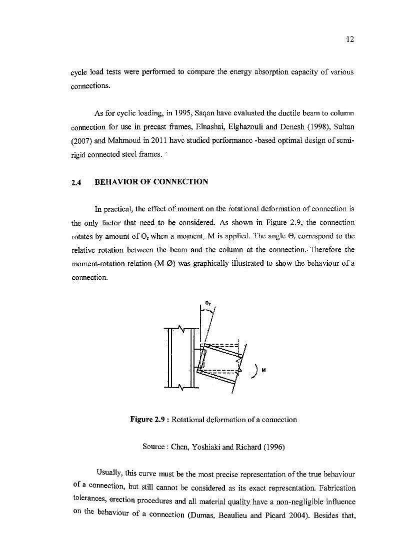
In practical, the effect of moment on the rotational deformation of connection is
the only factor that need to be considered. As shown in Figure 2.9, the connection
rotates by amount of Or when a moment, M is applied. The angle Or correspond to the
relative rotation between the beam and the column at the connection. Therefore the
moment-rotation relation. (M-ø) was :graphically illustrated to show the behaviour of a
connection.
or
)M
Figure 2.9 : Rotational deformation of a connection
Source: Chen, Yoshiaki and Richard (1996)
Usually, this curve must be the most precise representation of the true behaviour
of a connection but still cannot be considered as its exact representation. Fabrication
tolerances, erection procedures and all material quality, have a non-negligible • influence
on the behaviour of a connection (Dumas, Beaulieu and Picard 2004). Besides that,

13
based on the stress-strain graph, the yield strength also can represents the point where
behaviour changes from elastic to plastic. The ultimate tensile strength is the end point
of the stress-strain curve to represent the rupture of the material as in Figure 2.10.
Elastic limit ional or t I yield l,0i1t
Fracturepoint J'B
A :
Plastic behaviour
Elastic behaviour
.....Permanent set
Strain
Figure. 2.10: Stress-strain curve
Source: e-CAD Engineering (n.d)
Recent years, many experiments carried out focusing on the behavior of
connections have demonstrated that connections behave nonlinearly in the range
between the two extremes of fully rigid and frictionless pinned connections. The
behavior of the connection can be controlled by different modes related to relative
proportions of the components of the connection. White (2003) in his study stated that
connections are designed to control inelastic behavior either by flexural yielding of the
beam in combination with shear yielding of the column at panel zone, or by flexural
yielding of the beam alone.
2.4.1 Ductility
Ductility can be define as a material's ability to deform plastically and then absorbing energy before fracture. Ductility is specified with a non-linear stress-strain
behavior as shown in Figure 2.11. Steel is a material that display large post-yield strain
capacity prior to failure. This quality allows the material to convert strain energy to thermal energy during deformation (White, 2003).
a
557. MP8
414 MPa
216 MP
138 MPa
,tTTtA36
14
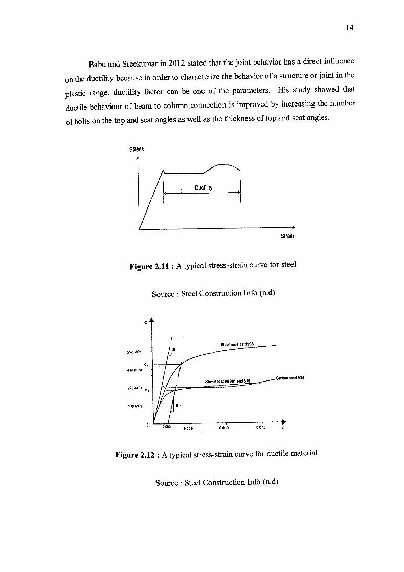
Babu and Sreekumar in 2012 stated that the joint behavior has a direct influence
on the ductility because in order to characterize the behavior of a structure or joint in the
plastic range, ductility factor can be one of the parameters. His study showed that
ductile behaviour of beam to column connection is improved by increasing the number
of bolts on the top and seat angles as well as the thickness of top and seat angles.
Stress
Strain
Figure 2.11 : A typical stress-strain curve for steel
Source: Steel Construction Info (n.d)
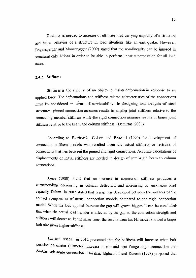
Figure 2.12 : A typical stress-strain curve for ductile material
Source : Steel Construction Info (n.d)
15
Ductility is needed to increase of ultimate load carrying capacity of a structure
and better behavior of a structure in load situations like an earthquake. However,
Bogensperger and Moosbrugger (2009) stated that the non-linearity can be ignored in
structural calculations in order to be able to perform linear Superposition for all load
cases.
2.4.2 Stiffness
Stiffness is the rigidity of an object to resists deformation in response to an
applied force. The deformations and stiffness-related characteristics of the connections
must be considered in terms of serviceability. In designing and analysis of steel
structures, pinned connection assumes results in smaller joint stiffhess relative to the
connecting member stiffness while the rigid connection assumes results in larger joint
stiffness relative to the beam and column stiffness, (Demirtas, 2003).
According to Bjorhovde, Colson and Brozetti (1990) the development of
connection stiffness models was resulted from the actual stiffness or restraint of
connections that lies between the pinned and rigid connections. Accurate calculations of
displacements or initial stiffness are needed in design of semi-rigid beam to column
connections.
Jones (1980) found that an increase in connection stiffness produces a
corresponding decreasing in column deflection and increasing in maximum load
capacity. Sultan in 2007 stated that a gap was developed between the surfaces of the
contact components of actual connection models compared to the rigid connection
model. When the load applied increase the gap will grows bigger. It can be concluded.
that when the actual load transfer is affected by the gap so the connection strength and
stiffness will decrease. In the same time, the results from his FE model showed a larger
bolt size gives higher stiffness.
Lin and Asada in 2012 presented that the stiffness will increase when bolt Position parameter (diameter) increase in top and seat flange angle connection and
double web angle connection Elnashai, Elghazouli and Danesh (1998) proposed that

--
Mode 1 Mode 3 Mode 4 Mode 2
16
changes to the thickness of the top and seat angles can influence the moment capacity
and rotational stiffness of the connection however not significantly influence the value
of the rotation at the estimated yield point.
2.4.3 Modes of failure
A number of studies were commenced to analyze the reasons for failure of the
steel connections. Winter . in 1956 categorised the failure of bolted connections into four
separate modes which are end pull-out, bearing, net section fracture and bolt shear.
Failures will occur in connections with and without welds on the shear connection
plates also at column to flange stiffeners (Shipp, 1994). Lin and Asada, 2012 have
studied 4 model and found that the failure mode due to tension failure of bolts. The
failure mode is illustrated in Figure 2.13. Their study revealed that failure mode 4 is the
best one, failure mode 1 and 2 should be avoided in order to achieve enough
deformation ability in connection design while while failure mode 3 is a possible true
failure mode in structural design and therefore it should be included in initial stiffness
investigation.
Figure 2.13 : Failure modes for semi-rigid connection
Source : Lin and Asada (2012)