Embed Size (px)
Citation preview
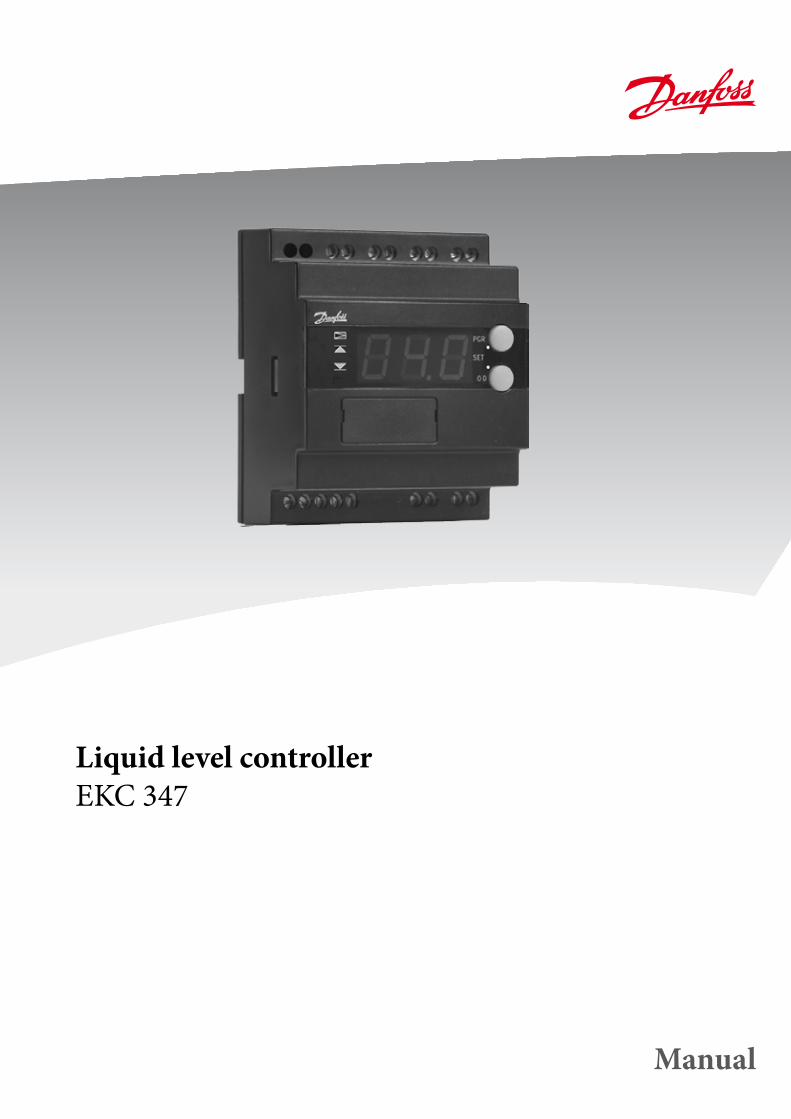
Liquid level controllerEKC 347
Manual
2 Manual RS8AX702 DKRCC.ES.R1.A1.02/ 520H4020 © Danfoss 01-2011 EKC 347
Introduction
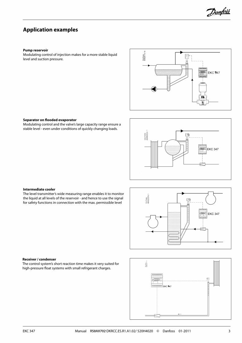
LED's on front panel
Opening signal to valve
Indication of upper level limit
Indication of lower level limit
Indication of alarm level
ApplicationThe controller is used for regulation of the refrigerant level in:
• Pump reservoirs
• Separators
• Intermediate coolers
• Economisers
• Condensers
• Receivers
Functions• Liquid level control• Alarm if the set alarm limits are exceeded• Relay outputs for upper and lower level limits and for alarm level• Analog input signal which can displace the reference• PI control• Low or High side control• When AKV/A is selected, a MASTER/SLAVE system can run up to 3
AKV/A with distributed Opening Degree• Manual control of output• Limitation of Opening degree possible• ON/OFF operation with hysteresis
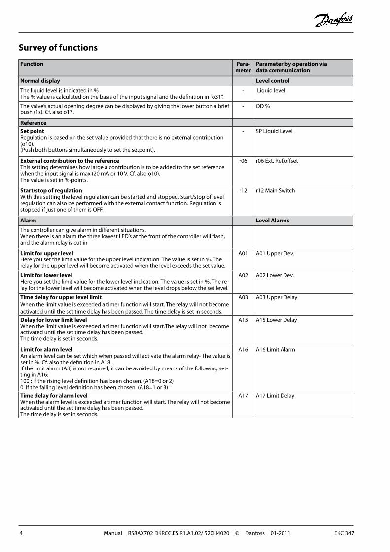
Extra options• PC operation
The controller can be provided with data communication, so that it may be hooked up with other products in the ADAP-KOOL® range of refrigeration controls. Operation, moni toring and data collection can then be performed from a PC - either in situ or at a service company.
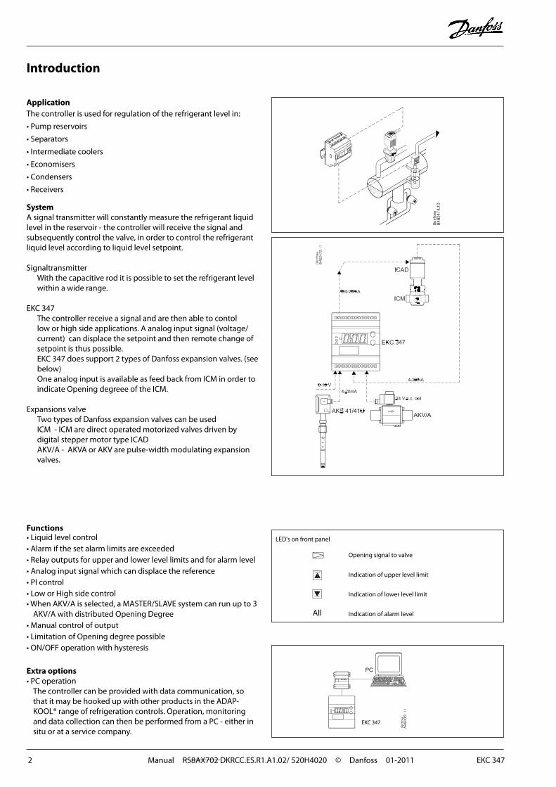
SystemA signal transmitter will constantly measure the refrigerant liquid level in the reservoir - the controller will receive the signal and subsequently control the valve, in order to control the refrigerant liquid level according to liquid level setpoint.
SignaltransmitterWith the capacitive rod it is possible to set the refrigerant level within a wide range.
EKC 347The controller receive a signal and are then able to contol low or high side applications. A analog input signal (voltage/ current) can displace the setpoint and then remote change of setpoint is thus possible.EKC 347 does support 2 types of Danfoss expansion valves. (see below)One analog input is available as feed back from ICM in order to indicate Opening degreee of the ICM.
Expansions valve Two types of Danfoss expansion valves can be usedICM - ICM are direct operated motorized valves driven by digital stepper motor type ICADAKV/A - AKVA or AKV are pulse-width modulating expansion valves.
EKC 347
All
EKC 347 Manual RS8AX702 DKRCC.ES.R1.A1.02/ 520H4020 © Danfoss 01-2011 3
Application examples
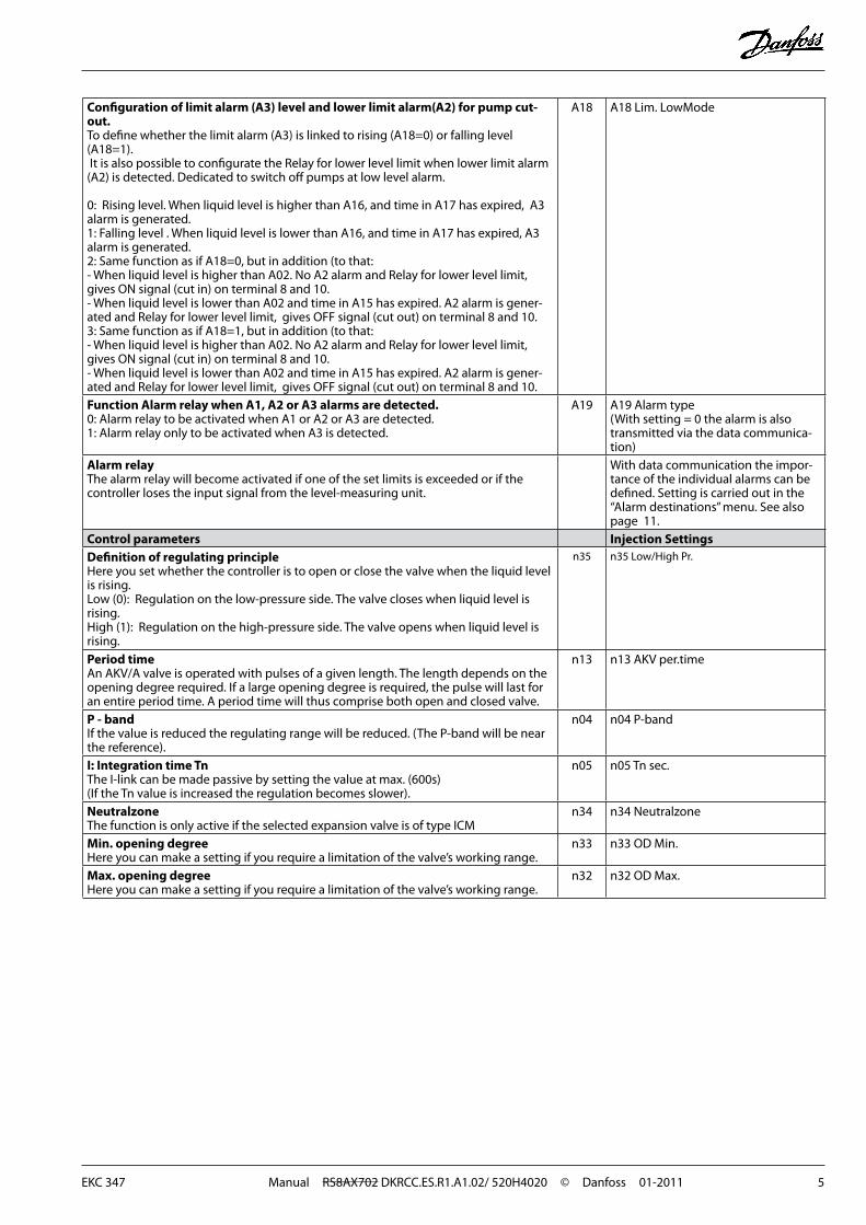
Pump reservoirModulating control of injection makes for a more stable liquid level and suction pressure.
Separator on flooded evaporatorModulating control and the valve’s large capacity range ensure a stable level - even under conditions of quickly changing loads.
Intermediate coolerThe level transmitter’s wide measuring range enables it to monitor the liquid at all levels of the reservoir - and hence to use the signal for safety functions in connection with the max. permissible level
Receiver / condenserThe control system’s short reaction time makes it very suited for high-pressure float systems with small refrigerant charges.
4 Manual RS8AX702 DKRCC.ES.R1.A1.02/ 520H4020 © Danfoss 01-2011 EKC 347
Survey of functions
Function Para- meter
Parameter by operation via data communication
Normal display Level control
The liquid level is indicated in %The % value is calculated on the basis of the input signal and the definition in ”o31”.
- Liquid level
The valve’s actual opening degree can be displayed by giving the lower button a brief push (1s). Cf. also o17.
- OD %
ReferenceSet pointRegulation is based on the set value provided that there is no external contribution (o10).(Push both buttons simultaneously to set the setpoint).
- SP Liquid Level
External contribution to the reference This setting determines how large a contribution is to be added to the set reference when the input signal is max (20 mA or 10 V. Cf. also o10). The value is set in %-points.
r06 r06 Ext. Ref.offset
Start/stop of regulationWith this setting the level regulation can be started and stopped. Start/stop of level regulation can also be performed with the external contact function. Regulation is stopped if just one of them is OFF.
r12 r12 Main Switch
Alarm Level Alarms
The controller can give alarm in different situations.When there is an alarm the three lowest LED’s at the front of the controller will flash, and the alarm relay is cut in
Limit for upper levelHere you set the limit value for the upper level indication. The value is set in %. The relay for the upper level will become activated when the level exceeds the set value.
A01 A01 Upper Dev.
Limit for lower levelHere you set the limit value for the lower level indication. The value is set in %. The re-lay for the lower level will become activated when the level drops below the set level.
A02 A02 Lower Dev.
Time delay for upper level limit When the limit value is exceeded a timer function will start. The relay will not become activated until the set time delay has been passed. The time delay is set in seconds.
A03 A03 Upper Delay
Delay for lower limit levelWhen the limit value is exceeded a timer function will start.The relay will not become activated until the set time delay has been passed.The time delay is set in seconds.
A15 A15 Lower Delay
Limit for alarm levelAn alarm level can be set which when passed will activate the alarm relay- The value is set in %. Cf. also the definition in A18.If the limit alarm (A3) is not required, it can be avoided by means of the following set-ting in A16:100 : If the rising level definition has been chosen. (A18=0 or 2)0: If the falling level definition has been chosen. (A18=1 or 3)
A16 A16 Limit Alarm
Time delay for alarm levelWhen the alarm level is exceeded a timer function will start. The relay will not become activated until the set time delay has been passed.The time delay is set in seconds.
A17 A17 Limit Delay
EKC 347 Manual RS8AX702 DKRCC.ES.R1.A1.02/ 520H4020 © Danfoss 01-2011 5
Configuration of limit alarm (A3) level and lower limit alarm(A2) for pump cut-out.To define whether the limit alarm (A3) is linked to rising (A18=0) or falling level (A18=1). It is also possible to configurate the Relay for lower level limit when lower limit alarm (A2) is detected. Dedicated to switch off pumps at low level alarm.
0: Rising level. When liquid level is higher than A16, and time in A17 has expired, A3 alarm is generated. 1: Falling level . When liquid level is lower than A16, and time in A17 has expired, A3 alarm is generated.2: Same function as if A18=0, but in addition (to that:- When liquid level is higher than A02. No A2 alarm and Relay for lower level limit, gives ON signal (cut in) on terminal 8 and 10.- When liquid level is lower than A02 and time in A15 has expired. A2 alarm is gener-ated and Relay for lower level limit, gives OFF signal (cut out) on terminal 8 and 10.3: Same function as if A18=1, but in addition (to that:- When liquid level is higher than A02. No A2 alarm and Relay for lower level limit, gives ON signal (cut in) on terminal 8 and 10.- When liquid level is lower than A02 and time in A15 has expired. A2 alarm is gener-ated and Relay for lower level limit, gives OFF signal (cut out) on terminal 8 and 10.
A18 A18 Lim. LowMode
Function Alarm relay when A1, A2 or A3 alarms are detected.0: Alarm relay to be activated when A1 or A2 or A3 are detected.1: Alarm relay only to be activated when A3 is detected.
A19 A19 Alarm type (With setting = 0 the alarm is also transmitted via the data communica-tion)
Alarm relayThe alarm relay will become activated if one of the set limits is exceeded or if the controller loses the input signal from the level-measuring unit.
With data communication the impor-tance of the individual alarms can be defined. Setting is carried out in the “Alarm destinations” menu. See also page 11.
Control parameters Injection SettingsDefinition of regulating principleHere you set whether the controller is to open or close the valve when the liquid level is rising.Low (0): Regulation on the low-pressure side. The valve closes when liquid level is rising.High (1): Regulation on the high-pressure side. The valve opens when liquid level is rising.
n35 n35 Low/High Pr.
Period timeAn AKV/A valve is operated with pulses of a given length. The length depends on the opening degree required. If a large opening degree is required, the pulse will last for an entire period time. A period time will thus comprise both open and closed valve.
n13 n13 AKV per.time
P - bandIf the value is reduced the regulating range will be reduced. (The P-band will be near the reference).
n04 n04 P-band
I: Integration time TnThe I-link can be made passive by setting the value at max. (600s)(If the Tn value is increased the regulation becomes slower).
n05 n05 Tn sec.
NeutralzoneThe function is only active if the selected expansion valve is of type ICM
n34 n34 Neutralzone
Min. opening degreeHere you can make a setting if you require a limitation of the valve’s working range.
n33 n33 OD Min.
Max. opening degreeHere you can make a setting if you require a limitation of the valve’s working range.
n32 n32 OD Max.
6 Manual RS8AX702 DKRCC.ES.R1.A1.02/ 520H4020 © Danfoss 01-2011 EKC 347
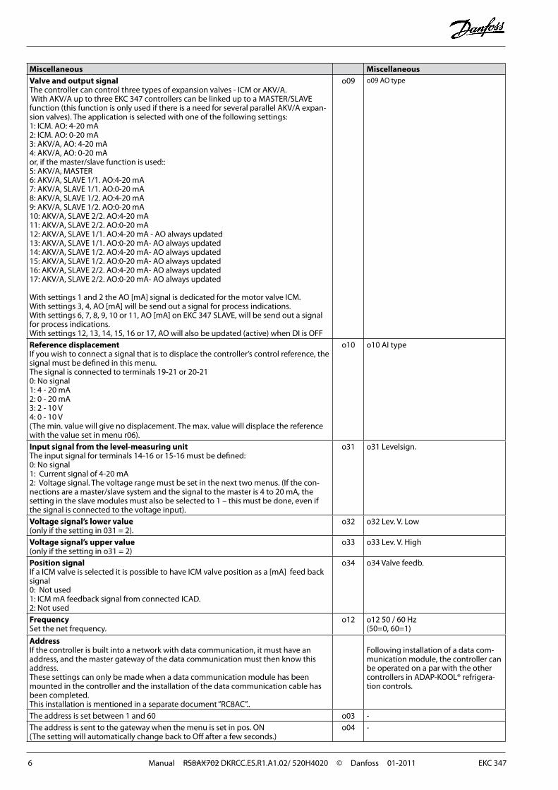
Miscellaneous MiscellaneousValve and output signalThe controller can control three types of expansion valves - ICM or AKV/A. With AKV/A up to three EKC 347 controllers can be linked up to a MASTER/SLAVE function (this function is only used if there is a need for several parallel AKV/A expan-sion valves). The application is selected with one of the following settings:1: ICM. AO: 4-20 mA2: ICM. AO: 0-20 mA3: AKV/A, AO: 4-20 mA4: AKV/A, AO: 0-20 mAor, if the master/slave function is used::5: AKV/A, MASTER6: AKV/A, SLAVE 1/1. AO:4-20 mA7: AKV/A, SLAVE 1/1. AO:0-20 mA8: AKV/A, SLAVE 1/2. AO:4-20 mA9: AKV/A, SLAVE 1/2. AO:0-20 mA10: AKV/A, SLAVE 2/2. AO:4-20 mA11: AKV/A, SLAVE 2/2. AO:0-20 mA12: AKV/A, SLAVE 1/1. AO:4-20 mA - AO always updated13: AKV/A, SLAVE 1/1. AO:0-20 mA- AO always updated14: AKV/A, SLAVE 1/2. AO:4-20 mA- AO always updated15: AKV/A, SLAVE 1/2. AO:0-20 mA- AO always updated16: AKV/A, SLAVE 2/2. AO:4-20 mA- AO always updated17: AKV/A, SLAVE 2/2. AO:0-20 mA- AO always updated
With settings 1 and 2 the AO [mA] signal is dedicated for the motor valve ICM. With settings 3, 4, AO [mA] will be send out a signal for process indications.With settings 6, 7, 8, 9, 10 or 11, AO [mA] on EKC 347 SLAVE, will be send out a signal for process indications.With settings 12, 13, 14, 15, 16 or 17, AO will also be updated (active) when DI is OFF
o09 o09 AO type
Reference displacementIf you wish to connect a signal that is to displace the controller’s control reference, the signal must be defined in this menu.The signal is connected to terminals 19-21 or 20-210: No signal1: 4 - 20 mA2: 0 - 20 mA3: 2 - 10 V4: 0 - 10 V(The min. value will give no displacement. The max. value will displace the reference with the value set in menu r06).
o10 o10 AI type
Input signal from the level-measuring unitThe input signal for terminals 14-16 or 15-16 must be defined:0: No signal1: Current signal of 4-20 mA2: Voltage signal. The voltage range must be set in the next two menus. (If the con-nections are a master/slave system and the signal to the master is 4 to 20 mA, the setting in the slave modules must also be selected to 1 – this must be done, even if the signal is connected to the voltage input).
o31 o31 Levelsign.
Voltage signal’s lower value(only if the setting in 031 = 2).
o32 o32 Lev. V. Low
Voltage signal’s upper value(only if the setting in o31 = 2)
o33 o33 Lev. V. High
Position signalIf a ICM valve is selected it is possible to have ICM valve position as a [mA] feed back signal0: Not used1: ICM mA feedback signal from connected ICAD.2: Not used
o34 o34 Valve feedb.
FrequencySet the net frequency.
o12 o12 50 / 60 Hz(50=0, 60=1)
AddressIf the controller is built into a network with data communication, it must have an address, and the master gateway of the data communication must then know this address.These settings can only be made when a data communication module has been mounted in the controller and the installation of the data communication cable has been completed.This installation is mentioned in a separate document “RC8AC”..
Following installation of a data com-munication module, the controller can be operated on a par with the other controllers in ADAP-KOOL® refrigera-tion controls.
The address is set between 1 and 60 o03 -The address is sent to the gateway when the menu is set in pos. ON(The setting will automatically change back to Off after a few seconds.)
o04 -
EKC 347 Manual RS8AX702 DKRCC.ES.R1.A1.02/ 520H4020 © Danfoss 01-2011 7
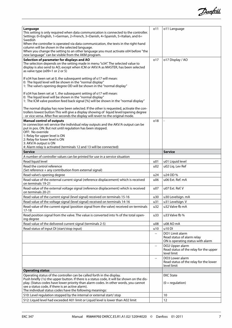
LanguageThis setting is only required when data communication is connected to the controller.Settings: 0=English, 1=German, 2=French, 3=Danish, 4=Spanish, 5=Italian, and 6= SwedishWhen the controller is operated via data communication, the texts in the right-hand column will be shown in the selected language.When you change the setting to an other language you must activate o04 before "the new language" can be visible from the AKM program.
o11 o11 Language
Selection of parameter for displays and AOThe selection depends on the setting made in menu ”o34”. The selected value to display is also send to AO, except when ICM or AKV/A as MASTER, has been selected as valve type (o09=1 or 2 or 5)
If o34 has been set at 0, the subsequent setting of o17 will mean:0: The liquid level will be shown in the ”normal display”1: The valve’s opening degree OD will be shown in the ”normal display”
If o34 has been set at 1, the subsequent setting of o17 will mean:0: The liquid level will be shown in the ”normal display”1: The ICM valve position feed back signal [%] will be shown in the ”normal display”
The normal display has now been selected. If the other is requested, activate the con-trollers lowest button This will give a display showing of liquid level/opening degree - or vice versa. After five seconds the display will revert to the original mode.
o17 o17 Display / AO
Manual control of outputsIn connection wit service the individual relay outputs and the AKV/A output can be put in pos. ON. But not until regulation has been stopped.OFF: No override1: Relay for upper level is ON2: Relay for lower level is ON3: AKV/A output is ON4: Alarm relay is activated (terminals 12 and 13 will be connected)
o18 -
Service ServiceA number of controller values can be printed for use in a service situationRead liquid level u01 u01 Liquid levelRead the control reference(Set reference + any contribution from external signal)
u02 u02 Liq. Lev Ref
Read valve’s opening degree u24 u24 OD %Read value of the external current signal (reference displacement) which is received on terminals 19-21
u06 u06 Ext. Ref. mA
Read value of the external voltage signal (reference displacement) which is received on terminals 20-21
u07 u07 Ext. Ref. V
Read value of the current signal (level signal) received on terminals 15-16 u30 u30 Levelsign. mARead value of the voltage signal (level signal) received on terminals 14-16 u31 u31 Levelsign. VRead value of the current signal (position signal from the valve) received on terminals 17-18
u32 u32 Valve fb mA
Read position signal from the valve. The value is converted into % of the total open-ing degree
u33 u33 Valve fb %
Read value of the delivered current signal (terminals 2-5) u08 u08 AO mARead status of input DI (start/stop input) u10 u10 DI
-- DO1 Limit alarmRead status of alarm relayON is operating status with alarm
-- DO2 Upper alarmRead status of the relay for the upper level limit
-- DO3 Lower alarmRead status of the relay for the lower level limit
Operating statusOperating status of the controller can be called forth in the display.Push briefly (1s) the upper button. If there is a status code, it will be shown on the dis-play. (Status codes have lower priority than alarm codes. In other words, you cannot see a status code, if there is an active alarm).The individual status codes have the following meanings:
EKC State
(0 = regulation)
S10: Level regulation stopped by the internal or external start/ stop 10
S12: Liquid level had exceeded A01 limit or Liquid level is lower than A02 limit 12
8 Manual RS8AX702 DKRCC.ES.R1.A1.02/ 520H4020 © Danfoss 01-2011 EKC 347
Operation Menu survey
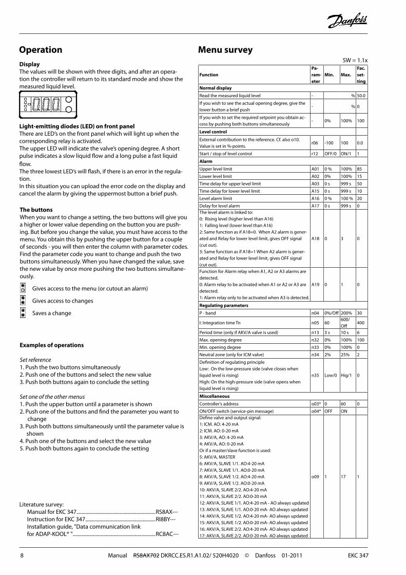
The buttonsWhen you want to change a setting, the two buttons will give you a higher or lower value depending on the button you are push-ing. But before you change the value, you must have access to the menu. You obtain this by pushing the upper button for a couple of seconds - you will then enter the column with parameter codes. Find the parameter code you want to change and push the two buttons simultaneously. When you have changed the value, save the new value by once more pushing the two buttons simultane-ously.
Gives access to the menu (or cutout an alarm)
Gives access to changes
Saves a change
Examples of operations
Set reference1. Push the two buttons simultaneously2. Push one of the buttons and select the new value3. Push both buttons again to conclude the setting Set one of the other menus1. Push the upper button until a parameter is shown2. Push one of the buttons and find the parameter you want to
change3. Push both buttons simultaneously until the parameter value is
shown4. Push one of the buttons and select the new value5. Push both buttons again to conclude the setting
SW = 1.1x
Literature survey: Manual for EKC 347 ..............................................................RS8AX--- Instruction for EKC 347 .......................................................RI8BY--- Installation guide, "Data communication link for ADAP-KOOL® " .................................................................RC8AC---
DisplayThe values will be shown with three digits, and after an opera-tion the controller will return to its standard mode and show the measured liquid level.
Light-emitting diodes (LED) on front panelThere are LED’s on the front panel which will light up when the corresponding relay is activated.The upper LED will indicate the valve’s opening degree. A short pulse indicates a slow liquid flow and a long pulse a fast liquid flow.The three lowest LED’s will flash, if there is an error in the regula-tion.In this situation you can upload the error code on the display and cancel the alarm by giving the uppermost button a brief push.
FunctionPa-ram-eter
Min. Max.Fac.set-ting
Normal display
Read the measured liquid level - % 50.0
If you wish to see the actual opening degree, give the lower button a brief push
- % 0
If you wish to set the required setpoint you obtain ac-cess by pushing both buttons simultaneously
- 0% 100% 100
Level control
External contribution to the reference. Cf. also o10. Value is set in %-points.
r06 -100 100 0.0
Start / stop of level control r12 OFF/0 ON/1 1
Alarm
Upper level limit A01 0 % 100% 85
Lower level limit A02 0% 100% 15
Time delay for upper level limit A03 0 s 999 s 50
Time delay for lower level limit A15 0 s 999 s 10
Level alarm limit A16 0 % 100 % 20
Delay for level alarm A17 0 s 999 s 0The level alarm is linked to:0: Rising level (higher level than A16)1: Falling level (lower level than A16)2: Same function as if A18=0. When A2 alarm is gener-ated and Relay for lower level limit, gives OFF signal (cut out).3: Same function as if A18=1 When A2 alarm is gener-ated and Relay for lower level limit, gives OFF signal (cut out).
A18 0 3 0
Function for Alarm relay when A1, A2 or A3 alarms are detected.0: Alarm relay to be activated when A1 or A2 or A3 are detected.1: Alarm relay only to be activated when A3 is detected.
A19 0 1 0
Regulating parameters
P - band n04 0%/Off 200% 30
I: Integration time Tn n05 60600/Off
400
Period time (only if AKV/A valve is used) n13 3 s 10 s 6
Max. opening degree n32 0% 100% 100
Min. opening degree n33 0% 100% 0
Neutral zone (only for ICM valve) n34 2% 25% 2
Definition of regulating principleLow: On the low-pressure side (valve closes when liquid level is rising)High: On the high-pressure side (valve opens when liquid level is rising)
n35 Low/0 Hig/1 0
Miscellaneous
Controller's address o03* 0 60 0
ON/OFF switch (service-pin message) o04* OFF ONDefine valve and output signal:1: ICM. AO: 4-20 mA2: ICM. AO: 0-20 mA3: AKV/A, AO: 4-20 mA4: AKV/A, AO: 0-20 mAOr if a master/slave function is used:5: AKV/A, MASTER6: AKV/A, SLAVE 1/1. AO:4-20 mA7: AKV/A, SLAVE 1/1. AO:0-20 mA8: AKV/A, SLAVE 1/2. AO:4-20 mA9: AKV/A, SLAVE 1/2. AO:0-20 mA10: AKV/A, SLAVE 2/2. AO:4-20 mA11: AKV/A, SLAVE 2/2. AO:0-20 mA12: AKV/A, SLAVE 1/1. AO:4-20 mA - AO always updated13: AKV/A, SLAVE 1/1. AO:0-20 mA- AO always updated14: AKV/A, SLAVE 1/2. AO:4-20 mA- AO always updated15: AKV/A, SLAVE 1/2. AO:0-20 mA- AO always updated16: AKV/A, SLAVE 2/2. AO:4-20 mA- AO always updated17: AKV/A, SLAVE 2/2. AO:0-20 mA- AO always updated
o09 1 17 1
EKC 347 Manual RS8AX702 DKRCC.ES.R1.A1.02/ 520H4020 © Danfoss 01-2011 9
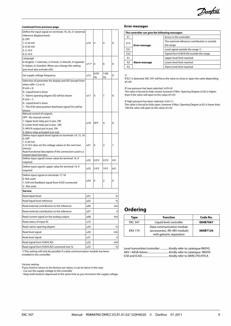
OrderingType Function Code No.
EKC 347 Liquid level controller 084B7067
EKA 174Data communication module
(accessories), (RS 485 module)with galvanic separation
084B7124
Level transmitter/controller: .............Kindly refer to catalogue RK0YGAKV / AKVA Valves: ................................Kindly refer to catalogue RK0YGICM and ICAD................ ..........................Kindly refer to DKRCI.PD.HT0.A
*) This setting will only be possible if a data communication module has been installed in the controller.
Factory settingIf you need to return to the factory-set values, it can be done in this way:- Cut out the supply voltage to the controller- Keep both buttons depressed at the same time as you recon nect the supply voltage
Error messages
The controller can give the following messages:
E1
Error message
Errors in the controller
E12The external reference contribution is outside the range
E21 Level signal outside the range 1)
E22 Signal from ICM/ICAD outside the range
A1
Alarm message
Upper level limit reached
A2 Lower level limit reached
A3 Alarm level limit reached
Define the input signal on terminals 19, 20, 21 (external reference displacement)0: OFF1: 4-20 mA2: 0-20 mA3: 2-10 V4: 0-10 V
o10 0 4 0
Language0=English, 1=German, 2=Frensh, 3=Danish, 4=Spanish, 5=Italian, 6=Swedish. When you change the setting you must also activate o04.
o11* 0 6 0
Set supply voltage frequency o120/50 Hz
1/60 Hz
0
Selection of parameter for display and AO (except from when o09=1,2 or 5)If o34 = 0:0: Liquid level is show1: Valve’s opening degree OD will be shownIf o34 = 1:0: Liquid level is show1: The ICM valve position feed back signal [%] will be shown
o17 0 1 0
Manual control of outputs:OFF: No manual control1: Upper level relay put in pos. ON2: Lower level relay put in pos. ON3: AKV/A output put in pos. ON4: Alarm relay activated (cut out)
o18 OFF 4 0
Define input signal (level signal) on terminals 14, 15, 160: OFF1: 4-20 mA2: 0-10 V (also set the voltage values in the next two menus) Read functional description if the connection used is a master/slave function.
o31 0 2 1
Define input signal’s lower value for terminal 14, if required
o32 0.0 V 4.9 V 4.0
Define input signal’s upper value for terminal 14, if required
o33 5.0 V 10 V 6.0
Define input signal on terminals 17-180: Not used1: ICM mA feedback signal from ICAD connected2: Not used
o34 0 2 0
Service
Read liquid level u01 %
Read liquid level reference u02 %
Read external contribution to the reference u06 mA
Read external contribution to the reference u07 V
Read current signal on the analog output u08 mA
Read status of input DI u10
Read valve’s opening degree u24 %
Read level signal u30 mA
Read level signal u31 V
Read signal from ICM/ICAD u32 mA
Read signal from ICM/ICAD converted into % u33 %
Continued from previous page
1)If E21 is detected. EKC 347 will force the valve to close or open the valve depending af n35
If Low pressure has been selected. (n35=0)The valve is forced to fully closed, however if Min. Opening Degree (n33) is higher than 0 the valve will open to the value of n33
If High pressure has been selected. (n35=1)The valve is forced to fully open, however if Max. Opening Degree (n32) is lower than 100 the valve will open to the value of n32
10 Manual RS8AX702 DKRCC.ES.R1.A1.02/ 520H4020 © Danfoss 01-2011 EKC 347
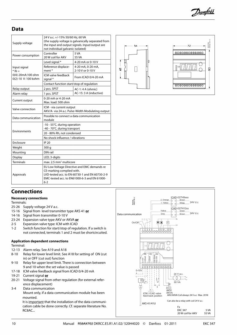
Connections
Data communication
FxEKC 347 5 VA20 W coil for AKV 55 VA
Necessary connectionsTerminals:25-26 Supply voltage 24 V a.c.15-16 Signal from level transmitter type AKS 41 or14-16 Signal from transmitter 0-10 V23-24 Expansion valve type AKV or AKVA or 2-5 Expansion valve type: ICM with ICAD1-2 Switch function for start/stop of regulation. If a switch is
not connected, terminals 1 and 2 must be shortcircuited.
Application dependent connectionsTerminal:12-13 Alarm relay. See A19 and A188-10 Relay for lower level limit. See A18 for setting of ON (cut
in) or OFF (cut out) function9-10 Relay for upper level limit. There is connection between
9 and 10 when the set value is passed17-18 ICM valve feedback signal from ICAD 0/4-20 mA19-21 Current signal or20-21 Voltage signal from other regulation (for external refer-
ence displacement)3-4 Data communication
Mount only, if a data communication module has been mounted.It is important that the installation of the data communi-cation cable be done correctly. Cf. separate literature No. RC8AC...
Data
Supply voltage
24 V a.c. +/-15% 50/60 Hz, 60 VA(the supply voltage is galvanically separated from the input and output signals. Input/output are not individual galvanic isolated)
Power consumptionController20 W coil for AKV
5 VA55 VA
Input signal * Ri =0(4)-20mA:100 ohm0(2)-10 V: 100 kohm
Level signal * 4-20 mA or 0-10 V
Reference displace-ment *
4-20 mA, 0-20 mA,2-10 V or 0-10 V
ICM valve feedback signal *
From ICAD 0/4-20 mA
Contact function start/stop of regulation
Relay output 2 pcs. SPST AC-1: 4 A (ohmic)AC-15: 3 A (inductive)Alarm relay 1 pcs. SPST
Current output0-20 mA or 4-20 mA Max. load: 500 ohm
Valve connectionICM - via current outputAKV/A- via 24 a.c. Pulse-Width Modulating output
Data communicationPossible to connect a data communication module
Environments
-10 - 55°C, during operation-40 - 70°C, during transport
20 - 80% Rh, not condensed
No shock influence / vibrations
Enclosure IP 20
Weight 300 g
Mounting DIN rail
Display LED, 3-digits
Terminals max. 2.5 mm2 multicore
Approvals
EU Low Voltage Directive and EMC demands re CE-marking complied with.LVD-tested acc. to EN 60730-1 and EN 60730-2-9EMC-tested acc. to EN61000-6-3 and EN 61000-6-2
AKS 41/41U
AKV/AKVA Coil always 24 V a.c Max. 20 W.
Can also be a relay with coil 24 V a.c.
EKC 347 Manual RS8AX702 DKRCC.ES.R1.A1.02/ 520H4020 © Danfoss 01-2011 11
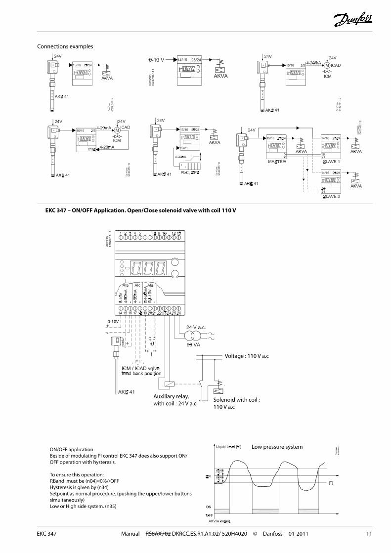
Connections examples
ON/OFF applicationBeside of modulating PI control EKC 347 does also support ON/OFF operation with hysteresis.
To ensure this operation:P.Band must be (n04)=0%//OFFHysteresis is given by (n34)Setpoint as normal procedure. (pushing the upper/lower buttons simultaneously)Low or High side system. (n35)
Low pressure system
EKC 347 – ON/OFF Application. Open/Close solenoid valve with coil 110 V
Voltage : 110 V a.c
Auxiliary relay, with coil : 24 V a.c
Solenoid with coil : 110 V a.c
0-10V
12 Manual RS8AX702 DKRCC.ES.R1.A1.02/ 520H4020 © Danfoss 01-2011 EKC 347
Danfoss can accept no responsibility for possible errors in catalogues, brochures and other printed material. Danfoss reserves the right to alter its products without notice. This also applies to products already on order provided that such alternations can be made without subsequential changes being necessary in specifications already agreed.All trademarks in this material are property of the respecitve companies. Danfoss and Danfoss logotype are trademarks of Danfoss A/S. All rights reserved. D
E-BD
EKC 347 Manual RS8AX702 DKRCC.ES.R1.A1.02/ 520H4020 © Danfoss 01-2011 13

14 Manual RS8AX702 DKRCC.ES.R1.A1.02/ 520H4020 © Danfoss 01-2011 EKC 347

EKC 347 Manual RS8AX702 DKRCC.ES.R1.A1.02/ 520H4020 © Danfoss 01-2011 15