Embed Size (px)
Citation preview
LIQUEFACTION MITIGATION IN SILTY SOILS USING DYNAMIC COMPACTION AND WICK DRAINS
R. NASHED1, S. THEVANAYAGAM2, G. R. MARTIN3, and T. SHENTHAN1
SUMMARY In recent years dynamic compaction (D.C) has become an economically attractive method of ground remediation of loose cohesionless soils for liquefaction hazards mitigation. The current practice for evaluating feasibility and choosing the operational parameters of the technique at a site depends mainly on field trials, past experience, and empirical equations based on reported records. A numerical simulation model has been developed to analyze the ground response and densification during D.C. This model is used to study the influence of silt content, hydraulic conductivity, impact energy, time lag between impact cycles, etc. and effectiveness of supplemental drains on densification of saturated liquefiable sands and non-plastic silty soil deposits during D.C. The results are compared with available field data. Results indicate that fines content and hydraulic conductivity influence the effectiveness of densification by D.C. With the aid of closely spaced wick drains, non-plastic silty soils with hydraulic conductivities as low as 10-8m/s can be densified by D.C. Further work is ongoing to develop design guidelines for D.C in sands and silty soils, based on this study.
INTRODUCTION Deep dynamic compaction is a proven technique for densification and liquefaction mitigation of sands containing little or no silt. It involves high-energy impacts to the ground surface by systematically dropping heavy weights of 6 to 35 tons from heights ranging from 12 to 40 m (Fig. 1a) to compact the underlying ground using heavy crawler cranes. No analytical methods are available for a detailed analysis and design of dynamic compaction for a given site. The current practice for D.C. processes depends mainly on previous experience or field test programs to determine the applicability and make site-specific design choices. Based on previous experience Lukas [1, 2] recommends a maximum depth of improvement (dmax) that can be achieved, given by:
dmax = n (WH)1/2 (1)
where W is the dropped weight in tonnes, and H is the height of drop in m. The value of n depends on soil type, and decreases with an increase in degree of saturation. ___________________________ 1 Ph.D. Candidate, State University of New York at Buffalo, USA. Email: [email protected] 2 Assoc. Prof., State University of New York at Buffalo, USA. Email: [email protected] 3 Prof., University of Southern California, USA. Email: [email protected]
13th World Conference on Earthquake Engineering Vancouver, B.C., Canada
August 1-6, 2004 Paper No. 1951
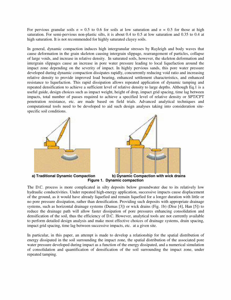
For pervious granular soils n = 0.5 to 0.6 for soils at low saturation and n = 0.5 for those at high saturation. For semi-pervious non-plastic silts, it is about 0.4 to 0.5 at low saturation and 0.35 to 0.4 at high saturation. It is not recommended for highly saturated clayey soils. In general, dynamic compaction induces high intergranular stresses by Rayleigh and body waves that cause deformation in the grain skeleton causing intergrain slippage, rearrangement of particles, collapse of large voids, and increase in relative density. In saturated soils, however, the skeleton deformation and intergrain slippages cause an increase in pore water pressure leading to local liquefaction around the impact zone depending on the severity of impact. In highly pervious sands, this pore water pressure developed during dynamic compaction dissipates rapidly, concurrently reducing void ratio and increasing relative density to provide improved load bearing, enhanced settlement characteristics, and enhanced resistance to liquefaction. This rapid dissipation allows repeated application of dynamic tamping and repeated densification to achieve a sufficient level of relative density to large depths. Although Eq.1 is a useful guide, design choices such as impact weight, height of drop, impact grid spacing, time lag between impacts, total number of passes required to achieve a specified level of relative density or SPT/CPT penetration resistance, etc. are made based on field trials. Advanced analytical techniques and computational tools need to be developed to aid such design analyses taking into consideration site-specific soil conditions.
a) Traditional Dynamic Compaction b) Dynamic Compaction with wick drains
Figure 1. Dynamic compaction
The D.C. process is more complicated in silty deposits below groundwater due to its relatively low hydraulic conductivities. Under repeated high-energy application, successive impacts cause displacement of the ground, as it would have already liquefied and remain liquefied for a longer duration with little or no pore pressure dissipation, rather than densification. Providing such deposits with appropriate drainage systems, such as horizontal drainage systems (Dumas [3]) or wick drains (Fig. 1b) (Dise [4], Han [5]) to reduce the drainage path will allow faster dissipation of pore pressures enhancing consolidation and densification of the soil, thus the efficiency of D.C. However, analytical tools are not currently available to perform detailed design analysis and make most effective choices of drainage systems, drain spacing, impact grid spacing, time lag between successive impacts, etc. at a given site. In particular, in this paper, an attempt is made to develop a relationship for the spatial distribution of energy dissipated in the soil surrounding the impact zone, the spatial distribution of the associated pore water pressure developed during impact as a function of the energy dissipated, and a numerical simulation of consolidation and quantification of densification of the soil surrounding the impact zone, under repeated tamping.
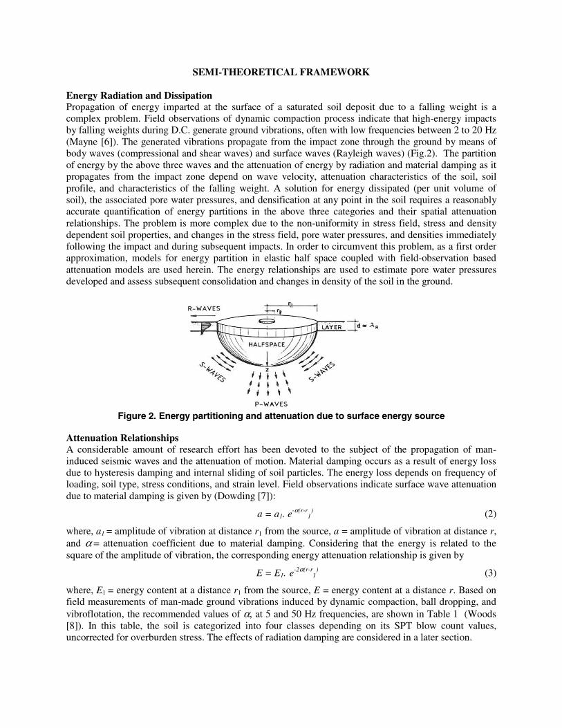
SEMI-THEORETICAL FRAMEWORK Energy Radiation and Dissipation Propagation of energy imparted at the surface of a saturated soil deposit due to a falling weight is a complex problem. Field observations of dynamic compaction process indicate that high-energy impacts by falling weights during D.C. generate ground vibrations, often with low frequencies between 2 to 20 Hz (Mayne [6]). The generated vibrations propagate from the impact zone through the ground by means of body waves (compressional and shear waves) and surface waves (Rayleigh waves) (Fig.2). The partition of energy by the above three waves and the attenuation of energy by radiation and material damping as it propagates from the impact zone depend on wave velocity, attenuation characteristics of the soil, soil profile, and characteristics of the falling weight. A solution for energy dissipated (per unit volume of soil), the associated pore water pressures, and densification at any point in the soil requires a reasonably accurate quantification of energy partitions in the above three categories and their spatial attenuation relationships. The problem is more complex due to the non-uniformity in stress field, stress and density dependent soil properties, and changes in the stress field, pore water pressures, and densities immediately following the impact and during subsequent impacts. In order to circumvent this problem, as a first order approximation, models for energy partition in elastic half space coupled with field-observation based attenuation models are used herein. The energy relationships are used to estimate pore water pressures developed and assess subsequent consolidation and changes in density of the soil in the ground.
Figure 2. Energy partitioning and attenuation due to surface energy source
Attenuation Relationships A considerable amount of research effort has been devoted to the subject of the propagation of man-induced seismic waves and the attenuation of motion. Material damping occurs as a result of energy loss due to hysteresis damping and internal sliding of soil particles. The energy loss depends on frequency of loading, soil type, stress conditions, and strain level. Field observations indicate surface wave attenuation due to material damping is given by (Dowding [7]):
a = a1. e-α(r-r
1) (2)
where, a1 = amplitude of vibration at distance r1 from the source, a = amplitude of vibration at distance r, and α = attenuation coefficient due to material damping. Considering that the energy is related to the square of the amplitude of vibration, the corresponding energy attenuation relationship is given by
E = E1. e-2α(r-r
1) (3)
where, E1 = energy content at a distance r1 from the source, E = energy content at a distance r. Based on field measurements of man-made ground vibrations induced by dynamic compaction, ball dropping, and vibroflotation, the recommended values of α, at 5 and 50 Hz frequencies, are shown in Table 1 (Woods [8]). In this table, the soil is categorized into four classes depending on its SPT blow count values, uncorrected for overburden stress. The effects of radiation damping are considered in a later section.
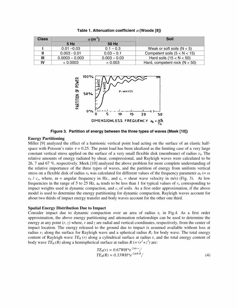
Table 1. Attenuation coefficient α (Woods [8])
Figure 3. Partition of energy between the three types of waves (Meek [10])
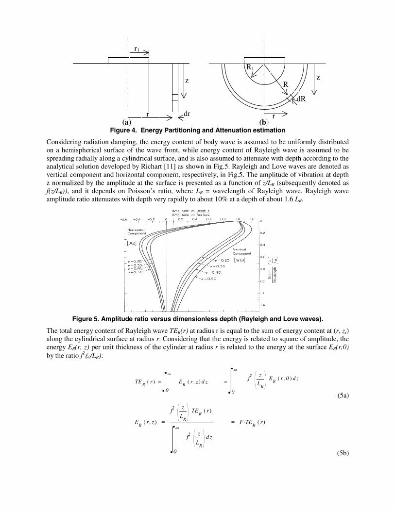
Energy Partitioning Miller [9] analyzed the effect of a harmonic vertical point load acting on the surface of an elastic half-space with Poisson’s ratio ν = 0.25. The point load has been idealized as the limiting case of a very large constant vertical stress applied on the surface of a very small flexible disk (membrane) of radius r0. The relative amounts of energy radiated by shear, compressional, and Rayleigh waves were calculated to be 26, 7 and 67 %, respectively. Meek [10] analyzed the above problem for more complete understanding of the relative importance of the three types of waves, and the partition of energy from uniform vertical stress on a flexible disk of radius r0 was calculated for different values of the frequency parameter a0 (= ω r0 / cs, where, ω = angular frequency in Hz., and cs = shear wave velocity in m/s) (Fig. 3). At low frequencies in the range of 5 to 25 Hz, a0 tends to be less than 1 for typical values of ro corresponding to impact weights used in dynamic compaction, and cs of soils. As a first order approximation, if the above model is used to determine the energy partitioning for dynamic compaction, Rayleigh waves account for about two thirds of impact energy transfer and body waves account for the other one third. Spatial Energy Distribution Due to Impact Consider impact due to dynamic compaction over an area of radius r1 in Fig.4. As a first order approximation, the above energy partitioning and attenuation relationships can be used to determine the energy at any point (r, z) where, r and z are radial and vertical coordinates, respectively, from the center of impact location. The energy released to the ground due to impact is assumed available without loss at radius r1 along the surface for Rayleigh wave and a spherical radius R1 for body wave. The total energy content of Rayleigh wave TER (r) along a cylindrical surface at radius r, and the total energy content of body wave TEB (R) along a hemispherical surface at radius R (=√r2+z2) are:
TER(r) = 0.67WH*e-2α(r-r1
) TEB(R) = 0.33WH*e-2α(R-R
1) (4)
α (m-1) Class 5 Hz 50 Hz
Soil
I 0.01 –0.03 0.1 – 0.3 Weak or soft soils (N < 5) II 0.003 - 0.01 0.03 – 0.1 Competent soils (5 < N < 15) III 0.0003 – 0.003 0.003 – 0.03 Hard soils (15 < N < 50) IV < 0.0003 < 0.003 Hard, competent rock (N > 50)
(a) (b)
Figure 4. Energy Partitioning and Attenuation estimation
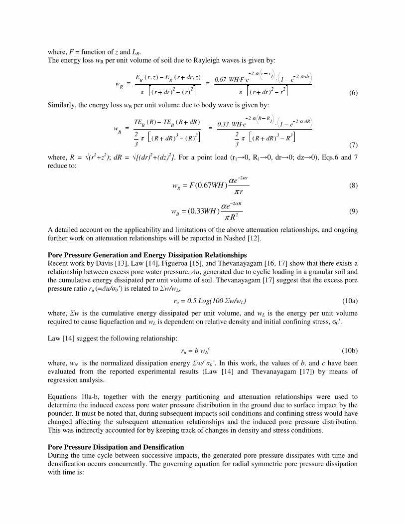
Considering radiation damping, the energy content of body wave is assumed to be uniformly distributed on a hemispherical surface of the wave front, while energy content of Rayleigh wave is assumed to be spreading radially along a cylindrical surface, and is also assumed to attenuate with depth according to the analytical solution developed by Richart [11] as shown in Fig.5. Rayleigh and Love waves are denoted as vertical component and horizontal component, respectively, in Fig.5. The amplitude of vibration at depth z normalized by the amplitude at the surface is presented as a function of z/LR (subsequently denoted as f(z/LR)), and it depends on Poisson’s ratio, where LR = wavelength of Rayleigh wave. Rayleigh wave amplitude ratio attenuates with depth very rapidly to about 10% at a depth of about 1.6 LR.
Figure 5. Amplitude ratio versus dimensionless depth (Rayleigh and Love waves).
The total energy content of Rayleigh wave TER(r) at radius r is equal to the sum of energy content at (r, zi) along the cylindrical surface at radius r. Considering that the energy is related to square of amplitude, the energy ER(r, z) per unit thickness of the cylinder at radius r is related to the energy at the surface ER(r,0) by the ratio f2(z/LR):
0
∞zf2
z
LR
ER
r 0,( ) dTE
Rr( ) =
0
∞zE
Rr z,( ) d =
(5a)
ER
r z,( ) =
f2z
LR
TER
r( )
0
∞zf2
z
LR
d
= F TER
. r( )
(5b)
r
r1
z R
dR
R1
z
r1
r dr
where, F = function of z and LR. The energy loss wR per unit volume of soil due to Rayleigh waves is given by:
wR
=E
Rr z,( ) E
Rr dr z,( )
π r dr( )2 r( )2= 0.67 WH F. e
2 α r r1. 1 e
2 α dr..
π r dr( )2 r2 (6)
Similarly, the energy loss wB per unit volume due to body wave is given by:
wB
=TE
BR( ) TE
BR dR( )
2
3π R dR( )3
R( )3
= 0.33 WH e2 α R R
1. 1 e 2 α dR..
2
3π R dR( )3
R3
(7)
where, R = √(r2+z2); dR = √[(dr)2+(dz)2]. For a point load (r1→0, R1→0, dr→0; dz→0), Eqs.6 and 7 reduce to:
2
(0.67 )r
R
ew F WH
r
ααπ
−
= (8)
2
2(0.33 )
R
B
ew WH
R
ααπ
−
= (9)
A detailed account on the applicability and limitations of the above attenuation relationships, and ongoing further work on attenuation relationships will be reported in Nashed [12]. Pore Pressure Generation and Energy Dissipation Relationships Recent work by Davis [13], Law [14], Figueroa [15], and Thevanayagam [16, 17] show that there exists a relationship between excess pore water pressure, ∆u, generated due to cyclic loading in a granular soil and the cumulative energy dissipated per unit volume of soil. Thevanayagam [17] suggest that the excess pore pressure ratio ru (=∆u/σ0’) is related to Σw/wL,
ru = 0.5 Log(100 Σw/wL) (10a)
where, Σw is the cumulative energy dissipated per unit volume, and wL is the energy per unit volume required to cause liquefaction and wL is dependent on relative density and initial confining stress, σ0’. Law [14] suggest the following relationship:
ru = b wNc (10b)
where, wN is the normalized dissipation energy Σw/ σ0’. In this work, the values of b, and c have been evaluated from the reported experimental results (Law [14] and Thevanayagam [17]) by means of regression analysis. Equations 10a-b, together with the energy partitioning and attenuation relationships were used to determine the induced excess pore water pressure distribution in the ground due to surface impact by the pounder. It must be noted that, during subsequent impacts soil conditions and confining stress would have changed affecting the subsequent attenuation relationships and the induced pore pressure distribution. This was indirectly accounted for by keeping track of changes in density and stress conditions. Pore Pressure Dissipation and Densification During the time cycle between successive impacts, the generated pore pressure dissipates with time and densification occurs concurrently. The governing equation for radial symmetric pore pressure dissipation with time is:
2
2
2
2 1
z
uC
r
u
rr
uC
dt
duvr ∂
∂+
∂∂+
∂∂= (11)
where, u=excess pore water pressure, and Cr and Cv are the coeff. of consolidation in the radial and vertical directions, respectively. During consolidation, the volumetric densification of a soil element is obtained by:
∫= '. σε dmvv (12a)
where, εv = volumetric strain, mv= coefficient of volume compressibility, and σ’=effective stress. Studies by Seed [18] on sands and Thevanayagam [16] on silty soils indicate that mv depends on pore pressure ratio ru and relative density Dr:
20
exp( )1; . ; 5(1.5 ); 3(4)
1 / 2r
u
Dbvr
v
m yy a r a D b
m y y−= ≥ = = − =
+ + (12b)
For silty sands, the above equation is modified to use (Drc)eq instead of Dr to take into account the effects of fines on volume compressibility (Shenthan [19]). Typical values for mv0 are adopted from Thevanayagam [20].
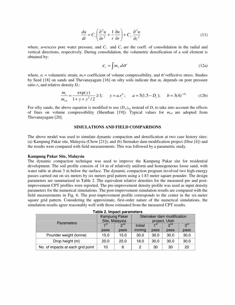
SIMULATIONS AND FIELD COMPARISONS The above model was used to simulate dynamic compaction and densification at two case history sites: (a) Kampung Pakar site, Malaysia (Chow [21]), and (b) Steinaker dam modification project (Dise [4]) and the results were compared with field measurements. This was followed by a parametric study. Kampung Pakar Site, Malaysia The dynamic compaction technique was used to improve the Kampung Pakar site for residential development. The soil profile consists of 14 m of relatively uniform and homogeneous loose sand, with water table at about 3 m below the surface. The dynamic compaction program involved two high-energy passes carried out on six meters by six meters grid pattern using a 1.83 meter square pounder. The design parameters are summarized in Table 2. The equivalent relative densities for the measured pre and post-improvement CPT profiles were reported. The pre-improvement density profile was used as input density parameters for the numerical simulations. The post-improvement simulation results are compared with the field measurements in Fig. 6. The post-improvement profile corresponds to the center in the six-meter square grid pattern. Considering the approximate, first-order nature of the numerical simulations, the simulation results agree reasonably well with those estimated from the measured CPT results.
Table 2. Impact parameters Kampung Paker Site, Malaysia
Steinaker dam modification project, Utah Parameters
1st pass
2nd pass
Initial ironing
1st pass
2nd pass
3rd pass
Pounder weight (tonne) 15.0 15.0 30.0 30.0 30.0 30.0
Drop height (m) 20.0 25.0 18.0 30.0 30.0 30.0
No. of impacts at each grid point 10 6 2 30 30 20
0
1
2
3
4
5
6
7
8
20 30 40 50 60 70 80 90 100
R ela tive d en sity , D r %D
epth
(m)
P r e - D C
P o s t - D C ( M e a s u r e d )
P o s t - D C ( S i m u la t e d )
2
3
4
5
6
7
8
9
10
11
0 20 40SPT - N1
Dep
th (m
)
Pre- D C
POST- D C ( M easured )
POST- D C ( Simulat ed )
Figure 6. Pre- and post-compaction Figure 7. Correlation between simulation measured and simulated relative density results and field measurements of post- (Kampung Pakar site, Malaysia). compaction SPT blow count (Steinaker dam modification project, Utah)
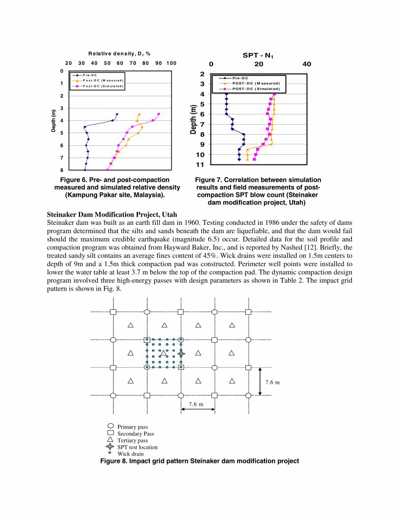
Steinaker Dam Modification Project, Utah Steinaker dam was built as an earth fill dam in 1960. Testing conducted in 1986 under the safety of dams program determined that the silts and sands beneath the dam are liquefiable, and that the dam would fail should the maximum credible earthquake (magnitude 6.5) occur. Detailed data for the soil profile and compaction program was obtained from Hayward Baker, Inc., and is reported by Nashed [12]. Briefly, the treated sandy silt contains an average fines content of 45%. Wick drains were installed on 1.5m centers to depth of 9m and a 1.5m thick compaction pad was constructed. Perimeter well points were installed to lower the water table at least 3.7 m below the top of the compaction pad. The dynamic compaction design program involved three high-energy passes with design parameters as shown in Table 2. The impact grid pattern is shown in Fig. 8.
Primary pass
Secondary Pass Tertiary pass SPT test location Wick drain
Figure 8. Impact grid pattern Steinaker dam modification project
7.6 m
7.6 m
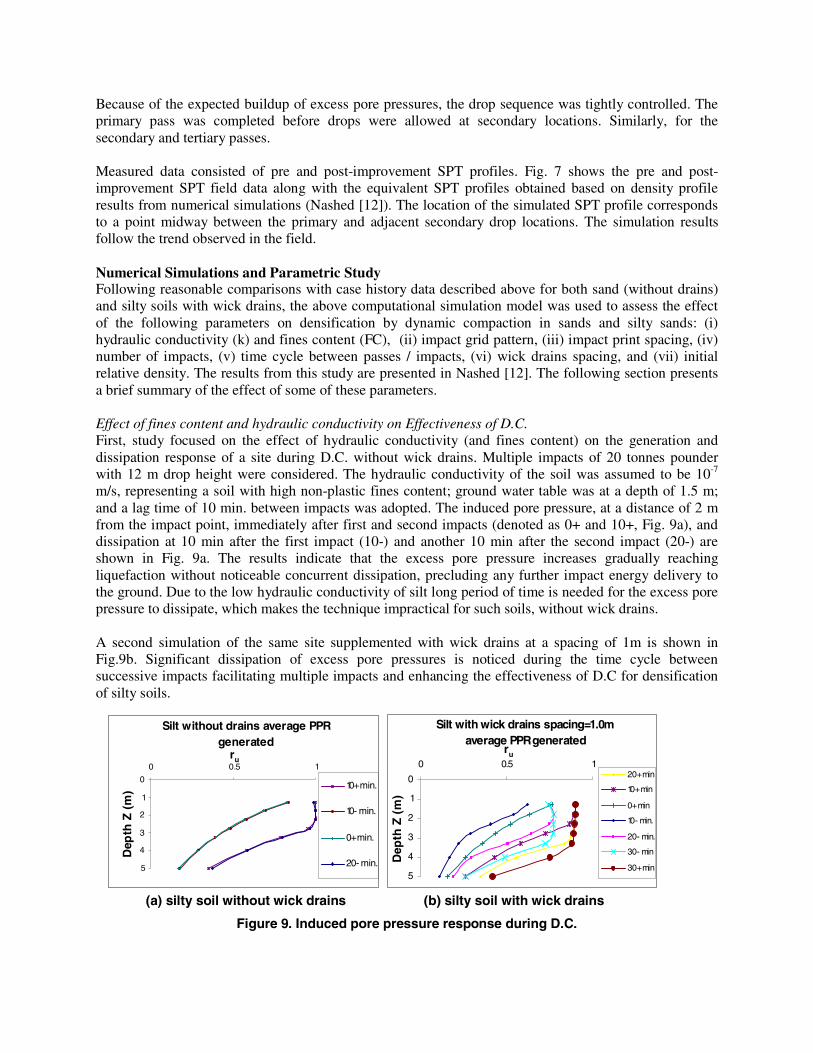
Because of the expected buildup of excess pore pressures, the drop sequence was tightly controlled. The primary pass was completed before drops were allowed at secondary locations. Similarly, for the secondary and tertiary passes. Measured data consisted of pre and post-improvement SPT profiles. Fig. 7 shows the pre and post-improvement SPT field data along with the equivalent SPT profiles obtained based on density profile results from numerical simulations (Nashed [12]). The location of the simulated SPT profile corresponds to a point midway between the primary and adjacent secondary drop locations. The simulation results follow the trend observed in the field. Numerical Simulations and Parametric Study Following reasonable comparisons with case history data described above for both sand (without drains) and silty soils with wick drains, the above computational simulation model was used to assess the effect of the following parameters on densification by dynamic compaction in sands and silty sands: (i) hydraulic conductivity (k) and fines content (FC), (ii) impact grid pattern, (iii) impact print spacing, (iv) number of impacts, (v) time cycle between passes / impacts, (vi) wick drains spacing, and (vii) initial relative density. The results from this study are presented in Nashed [12]. The following section presents a brief summary of the effect of some of these parameters. Effect of fines content and hydraulic conductivity on Effectiveness of D.C. First, study focused on the effect of hydraulic conductivity (and fines content) on the generation and dissipation response of a site during D.C. without wick drains. Multiple impacts of 20 tonnes pounder with 12 m drop height were considered. The hydraulic conductivity of the soil was assumed to be 10-7 m/s, representing a soil with high non-plastic fines content; ground water table was at a depth of 1.5 m; and a lag time of 10 min. between impacts was adopted. The induced pore pressure, at a distance of 2 m from the impact point, immediately after first and second impacts (denoted as 0+ and 10+, Fig. 9a), and dissipation at 10 min after the first impact (10-) and another 10 min after the second impact (20-) are shown in Fig. 9a. The results indicate that the excess pore pressure increases gradually reaching liquefaction without noticeable concurrent dissipation, precluding any further impact energy delivery to the ground. Due to the low hydraulic conductivity of silt long period of time is needed for the excess pore pressure to dissipate, which makes the technique impractical for such soils, without wick drains. A second simulation of the same site supplemented with wick drains at a spacing of 1m is shown in Fig.9b. Significant dissipation of excess pore pressures is noticed during the time cycle between successive impacts facilitating multiple impacts and enhancing the effectiveness of D.C for densification of silty soils.
Silt without drains average PPR generated
0
1
2
3
4
5
0 0.5 1ru
Dep
th Z
(m
) 10+ min.
10- min.
0+ min.
20- min.
Silt with wick drains spacing=1.0m average PPR generated
0
1
2
3
4
5
0 0.5 1
ru
Dep
th Z
(m
)
20+ min
10+ min
0+ min
10- min.
20- min.
30- min
30+ min
(a) silty soil without wick drains (b) silty soil with wick drains
Figure 9. Induced pore pressure response during D.C.
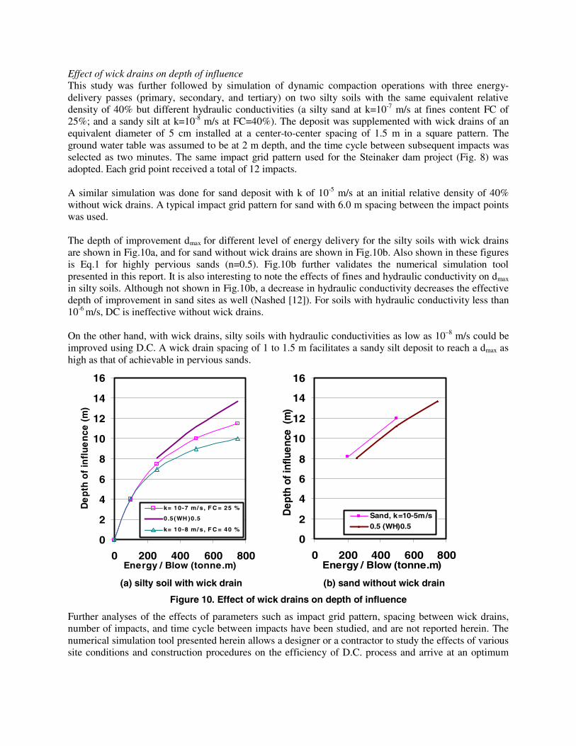
Effect of wick drains on depth of influence This study was further followed by simulation of dynamic compaction operations with three energy-delivery passes (primary, secondary, and tertiary) on two silty soils with the same equivalent relative density of 40% but different hydraulic conductivities (a silty sand at k=10-7 m/s at fines content FC of 25%; and a sandy silt at k=10-8 m/s at FC=40%). The deposit was supplemented with wick drains of an equivalent diameter of 5 cm installed at a center-to-center spacing of 1.5 m in a square pattern. The ground water table was assumed to be at 2 m depth, and the time cycle between subsequent impacts was selected as two minutes. The same impact grid pattern used for the Steinaker dam project (Fig. 8) was adopted. Each grid point received a total of 12 impacts. A similar simulation was done for sand deposit with k of 10-5 m/s at an initial relative density of 40% without wick drains. A typical impact grid pattern for sand with 6.0 m spacing between the impact points was used. The depth of improvement dmax for different level of energy delivery for the silty soils with wick drains are shown in Fig.10a, and for sand without wick drains are shown in Fig.10b. Also shown in these figures is Eq.1 for highly pervious sands (n=0.5). Fig.10b further validates the numerical simulation tool presented in this report. It is also interesting to note the effects of fines and hydraulic conductivity on dmax in silty soils. Although not shown in Fig.10b, a decrease in hydraulic conductivity decreases the effective depth of improvement in sand sites as well (Nashed [12]). For soils with hydraulic conductivity less than 10-6 m/s, DC is ineffective without wick drains. On the other hand, with wick drains, silty soils with hydraulic conductivities as low as 10–8 m/s could be improved using D.C. A wick drain spacing of 1 to 1.5 m facilitates a sandy silt deposit to reach a dmax as high as that of achievable in pervious sands.
0
2
4
6
8
10
12
14
16
0 200 400 600 800Energy / Blow (tonne.m)
De
pth
of
infl
ue
nce
(m
)
k= 10-7 m/ s, F C = 25 %
0.5(WH )0.5
k= 10-8 m/ s, F C = 40 %
0
2
4
6
8
10
12
14
16
0 200 400 600 800Energy / Blow (tonne.m)
Dep
th o
f inf
luen
ce (
m)
Sand, k=10-5m/s0.5 (WH)0.5
(a) silty soil with wick drain (b) sand without wick drain
Figure 10. Effect of wick drains on depth of influence
Further analyses of the effects of parameters such as impact grid pattern, spacing between wick drains, number of impacts, and time cycle between impacts have been studied, and are not reported herein. The numerical simulation tool presented herein allows a designer or a contractor to study the effects of various site conditions and construction procedures on the efficiency of D.C. process and arrive at an optimum
design choice beyond what is possible with the use of Eq.1. Final guidelines for using D.C. to densify saturated silty soils supplemented with wick drains are presented in Nashed [12].
CONCLUSION A semi-theoretical framework was developed to study the behavior of sands and non-plastic silty soils around the impact zone and their densification response during dynamic impact using a falling weight. Effects of site conditions, soil type, fines content, hydraulic conductivity, and construction parameters such as energy and number of impacts, sequence of impact, impact grid spacing, time cycle between impact, wick drains spacing on depth of influence, degree of improvement, were studied. The results indicate that silty soils with hydraulic conductivities as low as 10–8 m/s could be improved using the composite D.C. technique. The wick drains improve the drainage rate and decreases consolidation time, making it possible to repeatedly impact a silty soil deposit to achieve depth of improvement as high as that is possible in sand deposits. However, densification of such soils requires specially controlled sequence of impact to inhibit pore pressure buildup at any location. Decreasing drain spacing and increasing time cycle between impacts would improve dissipation of pore pressures, thus enhance densification.
The computational methodology presented herein is a powerful tool for design analyses of dynamic compaction taking into account of the site conditions and operational parameters for different deposits and site conditions. The model is expected to advance the use of DC in silty soils, and reduce the reliance on expensive field trials as a design tool. Further work is underway to develop design charts and design guidelines, to be reported in Nashed [12]. Acknowledgements Financial support for this research was provided by MCEER Highway Project 094, sponsored by the FHWA. J. Baez, Hayward Baker, Inc. provided field data and insights.
REFERENCES 1. Lukas RG. “Dynamic compaction for highway construction, Vol. 1, Design and construction
guidelines” Federal Highway Administration, Report No. FHWA/RD86/133, 1986. 2. Lukas RG. “Dynamic compaction” Federal Highway Administration, Report No. FHWA-SA-95-037,
1995. 3. Dumas JC, Nelson FB, and Jean-Francois M. “Dynamic compaction of saturated silt and silty sand –
A case history” ASCE, Geotechnical Special Publication No. 45, 1994: 80-89. 4. Dise K, Stevens, MG, and Von Thun JL. “Dynamic compaction to remediate liquefiable embankment
foundation soils” ASCE, Geotechnical Special Publication No. 45, 1994: 1-25. 5. Han, J. (1998). “Ground modification by a combination of dynamic compaction, consolidation, and
replacement”, Proceedings of the 4th International Conference on case histories in geotechnical Engineering, St. Louis, Missouri, pp.341-346.
6. Mayne PW. “Ground vibrations during dynamic compaction” Gazetas G, Selig ET, editors. ASCE, Vibration problems in geotechnical engineering, 1985: 247–265.
7. Dowding CH. “Construction vibrations” Upper Saddle River, NJ: Prentice Hall, 1996. 8. Woods RD, and Jedele LP. “Energy––attenuation from construction vibrations” Gazetas G, Selig ET,
editors. ASCE, Vibration problems in geotechnical engineering, 1985: 229–246. 9. Miller GF, and Pursey H. “On the partition of energy between elastic waves in a semi-infinite soild”
Proceedings of the Royal Society of London 1955; A233: 55-69. 10. Meek JW, and Wolf JP. “Cone models for nearly incompressible soil” Earthquake Engineering and
Structural Dynamics 1993; 22: 649-663.
11. Richart FE, Woods RD, and Hall JR. “Vibrations of soils and foundations” Englewood Cliffs, NJ: Prentice Hall, 1970.
12. Nashed R. “Liquefaction mitigation of silty soils using dynamic compaction” Ph.D. Dissertation, University at Buffalo, Buffalo, Ny, In Preparation, 2004.
13. Davis RO, and Berrill JB. “Energy dissipation and seismic liquefaction in sands” Earthquake Engineering and Structural Dynamics 1982; 10: 59-68.
14. Law KT, Cao YL, and He GN. “An energy approach for assessing seismic liquefaction potential” Canadian Geotechnical Journal 1990; 27: 320–329.
15. Figueroa JL, and Dahisaria N. “An energy approach in defining soil liquefaction” Proceedings of the 2nd International Conference on Recent Advances in Geotechnical Earthquake Engineering and Soil Dynamics, St. Louis, Missouri, Paper No. 3.17, 1991.
16. Thevanayagam S, Liang J, and Shenthan T. “Contact index and liquefaction potential for silty and gravely soils” Proceedings of the 14th ASCE Engineering Mechanics Conference, Austin, Texas, 2000.
17. Thevanayagam S, Kanagalingam T, and Shenthan T “Contact density – confining stress – energy to liquefaction”, Proceedings of the 15th ASCE Engineering Mechanics Conference, Columbia University, New York, NY, 2002.
18. Seed HB, Martin PP, and Lysmer J. “The generation and dissipation of pore water pressures during soil liquefaction” Earthquake Engineering Research Center, Report No. UCB/EERC 75-26, 1975.
19. Shenthan T. “Liquefaction mitigation in silty soils using composite stone column” Ph.D. Dissertation, University at Buffalo, Buffalo, NY, In Preparation, 2004.
20. Thevanayagam S, and Martin GR. “Liquefaction and post-liquefaction dissipation/densification characteristics of silty soils” MCEER, Annual Report for Research Year 1, FHWA Contract # DTFH61-98-C-00094: II85-98, Buffalo, NY, 2001.
21. Chow YK, Yong DM, Yong KY, and Lee SL. “Dynamic compaction analysis” ASCE, Journal of Geotechnical Engineering 1992; 118(8): 1141-1157.