Embed Size (px)
Citation preview
78-1294-250 2/14
LionelLCS SensorTrack™
Owner's Manual
2
Congratulations!
Your layout has always been more than the sum of its parts. But until now, combining those parts into a complete system could be a challenge. Lionel’s new Layout Control System or
“LCS,” fulfills the LEGACY promise of integrated locomotive and layout control.
The following Lionel marks are used throughout this Owner’s Manual and are protected under law. All rights reserved.
Lionel®, LEGACY™, FasTrack®, TrainMaster®, Odyssey®, RailSounds®, CrewTalk™, TowerCom™, DynaChuff™, StationSounds™, Pullmor®, ElectroCoupler™, Magne-Traction®, CAB-1® Remote Controller, American Flyer®, Lionel ZW®, ZW®, MagniVision®, TMCC®, Lionelville®, Wireless Tether™, Powerhouse™, LionMaster®, Conventional Classics™, Postwar Celebration Series™, TruRail™, PH-1 Powerhouse®, Powermaster®, Powerstation-Powerhouse®, Accessory Motor Controller™, AMC™, Accessory Switch Controller™, ASC™, Action Recorder Controller™, ARC™, Track Power Controller 300™, TPC 300™, Track Power Controller 400™, TPC 400™, Block Power Controller™, BPC™, Operating Track Controller™, OTC™, FatBoy™, Lionel Lines®, Joshua Lionel Cowen Series™, Lockon®, TrainSounds™, MultiHorn™, MultiWhistle™, Choo-Choo™, SensorTrack™
Table of contents
What is Lionel’s Layout Control System?How it works! 3LCS SensorTrack Features 4
Installing Your First LCS DeviceThe LCS DB-9 Cable with Power Supply 5Installing a new LCS system with Legacy Base 6-7Installing a new LCS system with Base-1L Command Base 8Installing LCS with Legacy AND TrainMaster Command Base 9-10Installing additional LCS devices 11
Configuring Your LCS DeviceSet SensorTrack TMCC ID and Action Command 12List of Action Commands 13-14About SensorTrack “Direction” 15Automatic CAB-2/Base Updates (Legacy base required) 16Viewing Locomotive Fuel Levels (Legacy base required) 17
Recording Actions on the LCS Sensor TrackChoosing a Recording Mode 18MODE 1: Recordings that apply to ALL passing LEGACY locomotives 19MODE 2: Recordings that play ONLY on one engine or train 20Recording ONLY the devices you specify (Mode 3) 21Erasing or Disabling Recordings 22Recording when you have more than one SensorTrack 22Creating Complex Recordings 23SensorTrack and the LCS iPad® App 24
ReferenceSensorTrack Quick Guide 25-26Operation of LEDs 27Specifications of the LCS SensorTrack 27Lionel Limited Warranty Policy and Service 28
3
What is Lionel’s Layout Control System?
Lionel’s Layout Control System or “LCS” doesn’t replace your existing Lionel Legacy Control system. It adds to it! You can control your layout from Lionel Cab Remote
controllers or from smart devices like an Apple iPad® to run locomotives, operate track switches, accessories and lighting. Create automatic events to control passing locomotives and other layout accessories or switches.
LCS is a modular system, with each product offering unique features. No single LCS product will do everything and not every layout will require every type of LCS device. But a fully realized LCS system will likely include the following:• A Lionel Command Base (Legacy or Base-1L) for locomotive control• LCS WiFi so you can control your layout from smart devices like an iPad®• LCS ASC2, to operate switches, lighting and accessories• LCS BPC2 for block power control• LCS SensorTrack (one or more) which adds a new level of interactivity with compatible
Lionel Legacy and Vision locomotives• LCS SER2 for computer control and use of existing Lionel serial devices like the TPC-300
and TPC-400
How it works!
As you know, your Lionel Cab Remote sends commands to your Command Base. In turn, the base controls your locomotives via a one-way communication link. LCS works in
parallel with your existing command base, adding a wired network of control modules. Spread across your layout, these LCS modules operate switches, lighting, accessories and track power blocks. LCS is bidirectional, meaning modules can send and receive commands.
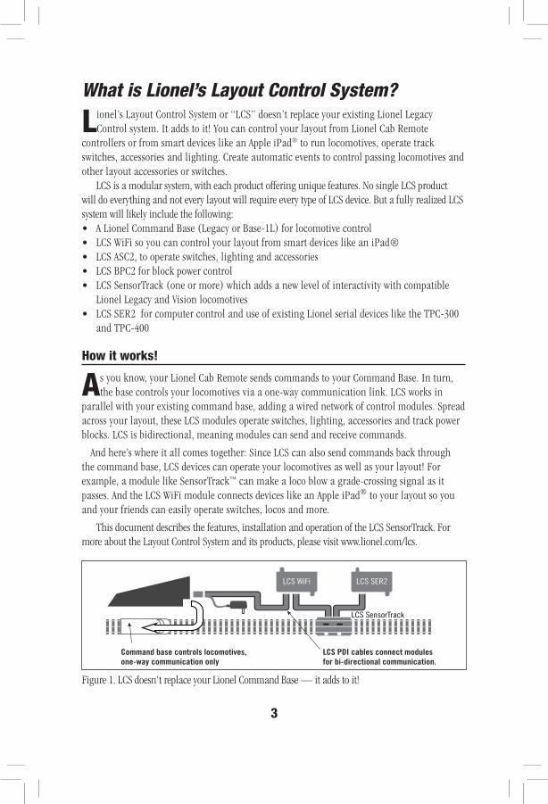
And here’s where it all comes together: Since LCS can also send commands back through the command base, LCS devices can operate your locomotives as well as your layout! For example, a module like SensorTrack™ can make a loco blow a grade-crossing signal as it passes. And the LCS WiFi module connects devices like an Apple iPad® to your layout so you and your friends can easily operate switches, locos and more.
This document describes the features, installation and operation of the LCS SensorTrack. For more about the Layout Control System and its products, please visit www.lionel.com/lcs.
LCS WiFi
LCS SensorTrack
LCS SER2
LCS PDI cables connect modules for bi-directional communication.
Command base controls locomotives,one-way communication only
Figure 1. LCS doesn't replace your Lionel Command Base — it adds to it!
4
LCS SensorTrack Features
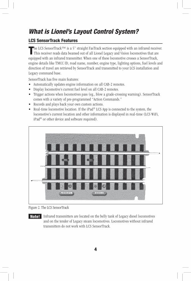
The LCS SensorTrack™ is a 5” straight FasTrack section equipped with an infrared receiver. This receiver reads data beamed out of all Lionel Legacy and Vision locomotives that are
equipped with an infrared transmitter. When one of these locomotive crosses a SensorTrack, engine details like TMCC ID, road name, number, engine type, lighting options, fuel levels and direction of travel are retrieved by SensorTrack and transmitted to your LCS installation and Legacy command base.
SensorTrack has five main features: • Automatically updates engine information on all CAB-2 remotes.• Display locomotive’s current fuel level on all CAB-2 remotes.• Trigger actions when locomotives pass (eg., blow a grade-crossing warning). SensorTrack
comes with a variety of pre-programmed “Action Commands.” • Records and plays back your own custom actions.• Real-time locomotive location. If the iPad® LCS App is connected to the system, the
locomotive’s current location and other information is displayed in real-time (LCS WiFi, iPad® or other device and software required).
Infrared transmitters are located on the belly tank of Legacy diesel locomotives and on the tender of Legacy steam locomotives. Locomotives without infrared transmitters do not work with LCS SensorTrack.
Figure 2. The LCS SensorTrack
Note!
What is Lionel’s Layout Control System?
5
Installing Your First LCS Device
The following section describes installation of a new LCS system. If you already have installed your first LCS component, please skip ahead to the next section titled “Installing
additional LCS devices.”When installing a new LCS system, the process you will follow depends on which Lionel
Command Base is to be connected to your LCS system. Following sections describe starting a new LCS installation with a Legacy Base or a Base-L1.
The LCS DB-9 Cable with Power Supply
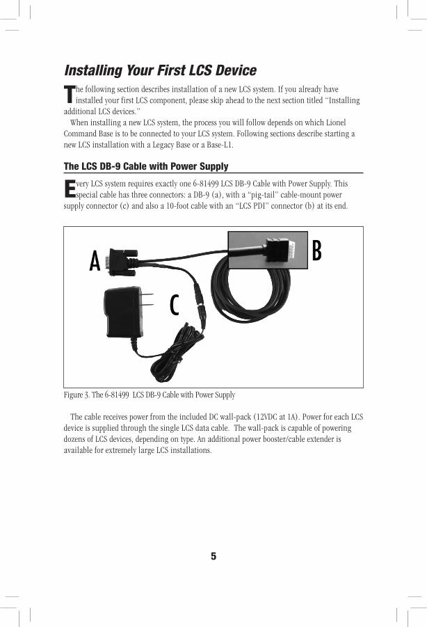
Every LCS system requires exactly one 6-81499 LCS DB-9 Cable with Power Supply. This special cable has three connectors: a DB-9 (a), with a “pig-tail” cable-mount power
supply connector (c) and also a 10-foot cable with an “LCS PDI” connector (b) at its end.
The cable receives power from the included DC wall-pack (12VDC at 1A). Power for each LCS device is supplied through the single LCS data cable. The wall-pack is capable of powering dozens of LCS devices, depending on type. An additional power booster/cable extender is available for extremely large LCS installations.
Figure 3. The 6-81499 LCS DB-9 Cable with Power Supply
6
Installing a new LCS system with Legacy Base
To install a new LCS system on a layout with a Legacy Command Base:
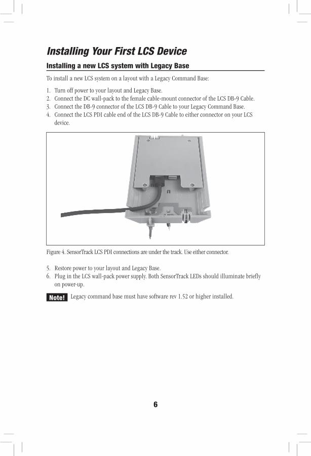
1. Turn off power to your layout and Legacy Base.2. Connect the DC wall-pack to the female cable-mount connector of the LCS DB-9 Cable.3. Connect the DB-9 connector of the LCS DB-9 Cable to your Legacy Command Base.4. Connect the LCS PDI cable end of the LCS DB-9 Cable to either connector on your LCS
device.
5. Restore power to your layout and Legacy Base.6. Plug in the LCS wall-pack power supply. Both SensorTrack LEDs should illuminate briefly
on power-up.
Legacy command base must have software rev 1.52 or higher installed.
Figure 4. SensorTrack LCS PDI connections are under the track. Use either connector.
Note!
Installing Your First LCS Device
7
Installing a new LCS system with Legacy Base (continued)
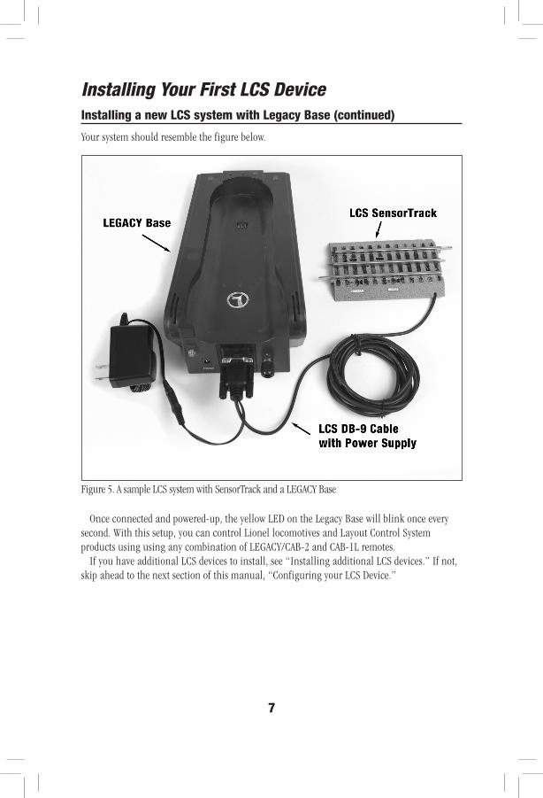
Your system should resemble the figure below.
Once connected and powered-up, the yellow LED on the Legacy Base will blink once every second. With this setup, you can control Lionel locomotives and Layout Control System products using using any combination of LEGACY/CAB-2 and CAB-1L remotes.
If you have additional LCS devices to install, see “Installing additional LCS devices.” If not, skip ahead to the next section of this manual, “Configuring your LCS Device.”
Figure 5. A sample LCS system with SensorTrack and a LEGACY Base
Installing Your First LCS Device
8
Installing a new LCS system with Base-1L Command Base
To install a new LCS system on a layout with a Base-1L Command Base:
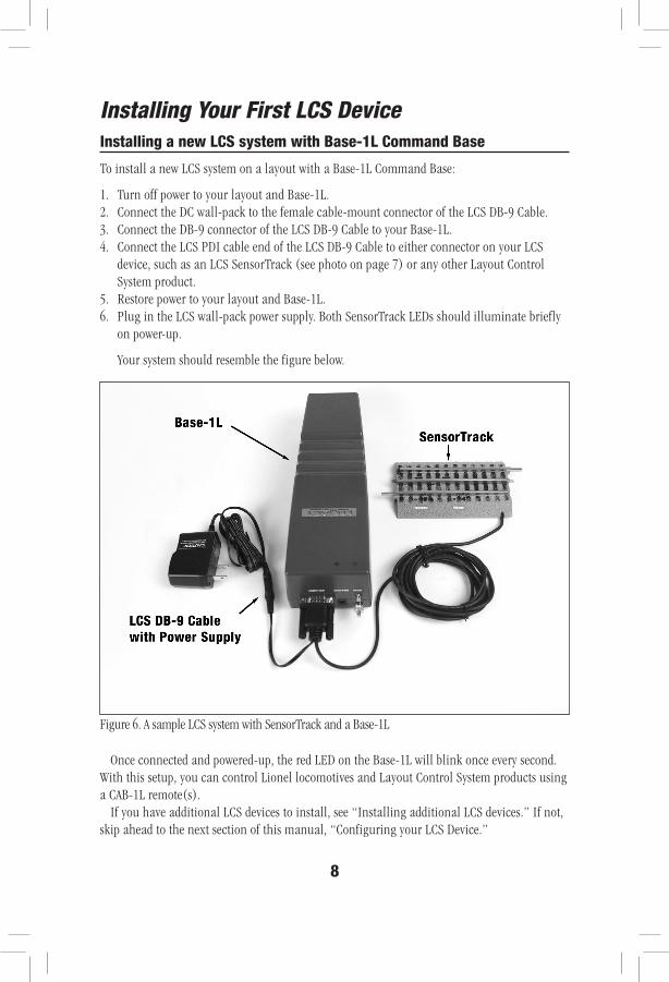
1. Turn off power to your layout and Base-1L.2. Connect the DC wall-pack to the female cable-mount connector of the LCS DB-9 Cable.3. Connect the DB-9 connector of the LCS DB-9 Cable to your Base-1L.4. Connect the LCS PDI cable end of the LCS DB-9 Cable to either connector on your LCS
device, such as an LCS SensorTrack (see photo on page 7) or any other Layout Control System product.
5. Restore power to your layout and Base-1L. 6. Plug in the LCS wall-pack power supply. Both SensorTrack LEDs should illuminate briefly
on power-up.
Your system should resemble the figure below.
Once connected and powered-up, the red LED on the Base-1L will blink once every second. With this setup, you can control Lionel locomotives and Layout Control System products using a CAB-1L remote(s).
If you have additional LCS devices to install, see “Installing additional LCS devices.” If not, skip ahead to the next section of this manual, “Configuring your LCS Device.”
Figure 6. A sample LCS system with SensorTrack and a Base-1L
Installing Your First LCS Device
9
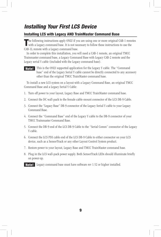
Installing LCS with Legacy AND TrainMaster Command Base
The following instructions apply ONLY if you are using one or more original CAB-1 remotes with a Legacy command base. It is not necessary to follow these instructions to use the
CAB-1L remote with a Legacy command base.In order to complete this installation, you will need a CAB-1 remote, an original TMCC
Trainmaster command base, a Legacy Command Base with Legacy CAB-2 remote and the Legacy serial Y cable (included with the Legacy command base).
This is the ONLY supported application for the Legacy Y cable. The “Command base” end of the Legacy Serial Y cable cannot be directly connected to any accessory other than the original TMCC TrainMaster command base.
To install a new LCS system on a layout with a Legacy Command Base, an original TMCC Command Base and a Legacy Serial Y Cable:
1. Turn off power to your layout, Legacy Base and TMCC TrainMaster command base.
2. Connect the DC wall-pack to the female cable-mount connector of the LCS DB-9 Cable.
3. Connect the "Legacy Base" DB-9 connector of the Legacy Serial Y cable to your Legacy Command Base.
4. Connect the “Command Base” end of the Legacy Y cable to the DB-9 connector of your TMCC Trainmaster Command Base.
5. Connect the DB-9 end of the LCS DB-9 Cable to the “Serial Comm” connector of the Legacy Y cable.
6. Connect the LCS PDI cable end of the LCS DB-9 Cable to either connector on your LCS device, such as a SensorTrack or any other Layout Control System product.
7. Restore power to your layout, Legacy Base and TMCC TrainMaster command base.
8. Plug in the LCS wall-pack power supply. Both SensorTrack LEDs should illuminate briefly on power-up.
Legacy command base must have software rev 1.52 or higher installed.
Note!
Note!
Installing Your First LCS Device
10
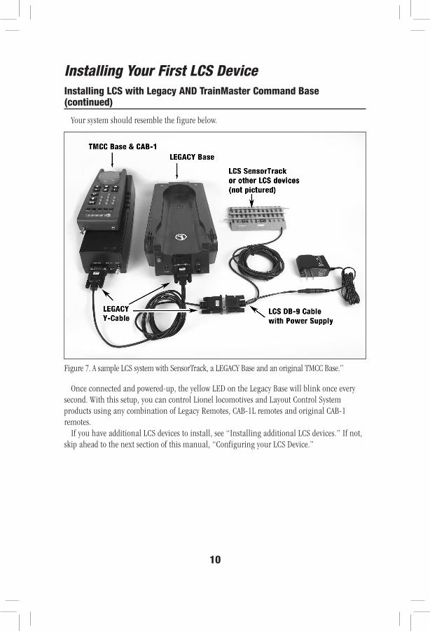
Your system should resemble the figure below.
Once connected and powered-up, the yellow LED on the Legacy Base will blink once every second. With this setup, you can control Lionel locomotives and Layout Control System products using any combination of Legacy Remotes, CAB-1L remotes and original CAB-1 remotes.
If you have additional LCS devices to install, see “Installing additional LCS devices.” If not, skip ahead to the next section of this manual, “Configuring your LCS Device.”
Installing LCS with Legacy AND TrainMaster Command Base (continued)
Figure 7. A sample LCS system with SensorTrack, a LEGACY Base and an original TMCC Base.”
Installing Your First LCS Device
11
Installing additional LCS devices
This section describes adding a new device to an existing Layout Control System installation. If you are installing a brand new LCS system, please refer to the previous
section of this document, “Installing Your First LCS Device.”Adding additional LCS devices to an existing Layout Control System requires an additional
cable for each new device. These “LCS PDI Cables” come in a variety of pre-made lengths. They are not included with LCS devices, and must be purchased separately. LCS PDI Cables are available in a variety of lengths:
6-81500 - LCS PDI 1ft Cable6-81501 - LCS PDI 3ft Cable 6-81502 - LCS PDI 10ft Cable 6-81503 - LCS PDI 20ft Cable
Each new device is connected via LCS PDI cables in a “daisy-chain” fashion (one to the next, and so on). The order of devices in the “chain” is up to you. The only exception is that an LCS WiFi must be the first device in the chain if no Lionel Command Base is present.
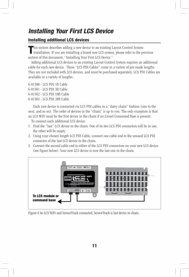
To connect each additional LCS device:1. Find the “last” LCS device in the chain. One of its two LCS PDI connectors will be in use,
the other will be empty. 2. Using your chosen length LCS PDI Cable, connect one cable end to the unused LCS PDI
connector of the last LCS device in the chain.3. Connect the second cable end to either of the LCS PDI connectors on your new LCS device
(see figure below). Your new LCS device is now the last one in the chain.
LCS PDI CABLESuse either connector
WiFi
6-81325
To LCS module orcommand base
Figure 8 An LCS WiFi and SensorTrack connected, SensorTrack is last device in chain.
Installing Your First LCS Device
12
Configuring Your LCS Device Set SensorTrack TMCC ID and Action Command
Before using each SensorTrack on your layout, you must program it with a unique TMCC Accessory ID. If you have other existing TMCC-controlled accessories on your layout, be
sure to assign each SensorTrack a unique ID that does not conflict with other devices.Each time you set TMCC Accessory ID, you must also assign one of 10 “action commands.”
In the first example, we’ll use Action Command 0, which is “no action.” Similarly, each time you change the Action Command, you must first enter the TMCC ACC ID number. A description of all Action Commands appears later in this document.
To set the ID and Action Command 0 (no action):
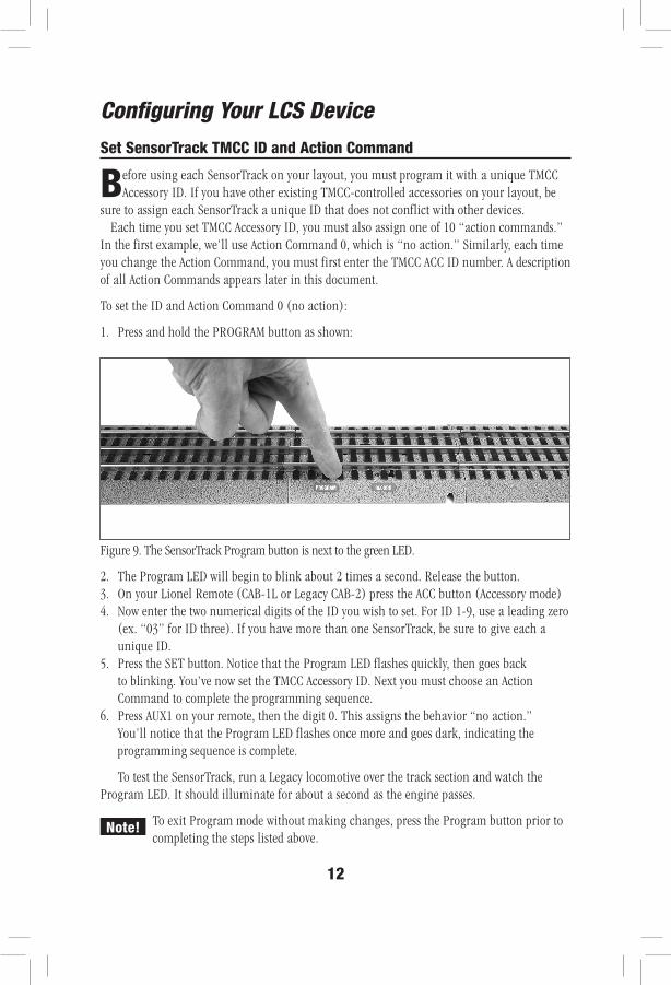
1. Press and hold the PROGRAM button as shown:
2. The Program LED will begin to blink about 2 times a second. Release the button.3. On your Lionel Remote (CAB-1L or Legacy CAB-2) press the ACC button (Accessory mode)4. Now enter the two numerical digits of the ID you wish to set. For ID 1-9, use a leading zero
(ex. “03” for ID three). If you have more than one SensorTrack, be sure to give each a unique ID.
5. Press the SET button. Notice that the Program LED flashes quickly, then goes back to blinking. You’ve now set the TMCC Accessory ID. Next you must choose an Action Command to complete the programming sequence.
6. Press AUX1 on your remote, then the digit 0. This assigns the behavior “no action.” You’ll notice that the Program LED flashes once more and goes dark, indicating the programming sequence is complete.
To test the SensorTrack, run a Legacy locomotive over the track section and watch the Program LED. It should illuminate for about a second as the engine passes.
To exit Program mode without making changes, press the Program button prior to completing the steps listed above.
Figure 9. The SensorTrack Program button is next to the green LED.
Note!
13
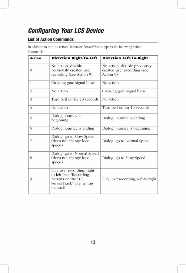
List of Action Commands
In addition to the “no action” behavior, SensorTrack supports the following Action Commands:
Configuring Your LCS Device
Action Direction Right-To-Left Direction Left-To-Right
0 No action; disable previously created user recording (see Action 9)
No action; disable previously created user recording (see Action 9)
1 Crossing gate signal blow No action
2 No action Crossing gate signal blow
3 Turn bell on for 10 seconds No action
4 No action Turn bell on for 10 seconds
5 Dialog, journey is beginning
Dialog, journey is ending
6 Dialog, journey is ending Dialog, journey is beginning
7 Dialog, go to Slow Speed (does not change loco speed)
Dialog, go to Normal Speed
8 Dialog, go to Normal Speed (does not change loco speed)
Dialog, go to Slow Speed
9
Play user recording, right-to-left (see "Recording Actions on the LCS SensorTrack" later in this manual)
Play user recording, left-to-right
14
List of Action Commands (continued)
Let’s experiment with Action Command 1, which automatically blows a grade-crossing signal when passing in one direction over the SensorTrack.
To set TMCC ID and Action Command 1 (sound crossing signal):
1. Press and hold the Program button until it begins blinking.2. Release the Program button.3. On your Lionel Remote (CAB-1L or Legacy CAB-2) press the ACC button (Accessory mode)4. Now enter the two numerical digits of the ID you wish to set. For ID 1-9, use a leading zero
(ex. “01” for ID one).5. Press the SET button. Notice that the Program LED flashes quickly, then goes back to
blinking. You’ve set the TMCC ID, now you must choose an Action Command to complete the programming sequence.
6. Press AUX1 on your remote, then the digit 1. This assigns the action “blow grade crossing signal.” You’ll notice that the Program LED flashes once more and then goes dark. This indicates the programming sequence is complete.
Now, run a Legacy locomotive over SensorTrack and watch the Program LED. It should illuminate for about a second as the engine passes. If you’re traveling in the right-to-left direction (see next page), you should hear the locomotive sound a grade-crossing on its horn or whistle. If not, reverse direction and pass over the SensorTrack moving from right-to-left to hear the crossing signal play.
To change the grade crossing signal to a different action command, repeat the above sequence, substituting a different digit for the desired command.
Configuring Your LCS Device
15
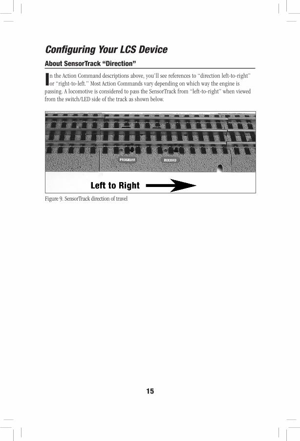
About SensorTrack “Direction”
In the Action Command descriptions above, you’ll see references to “direction left-to-right” or “right-to-left.” Most Action Commands vary depending on which way the engine is
passing. A locomotive is considered to pass the SensorTrack from “left-to-right” when viewed from the switch/LED side of the track as shown below.
Configuring Your LCS Device
Figure 9. SensorTrack direction of travel
16
Automatic CAB-2/Base Updates (Legacy base required)
The first time a new engine crosses a SensorTrack, you’ll notice that CAB-2 engine information will update, including the road name, road number locomotive type, and
lighting keypad options. For most layouts, automatically updating the LEGACY Base database is a desirable feature. However, some clubs may prefer not to automatically load visiting engine’s info. This can be controlled for all SensorTracks on the layout using your Lionel hand-held remote.
To disable automatic base updates:
• From your remote, enter ACC, 99, AUX1, 3 • All SensorTracks on the layout will no longer update the Legacy command base when a
compatible locomotive passes.
The base update feature will remain disabled even when the track power is turned off and then on again.
To turn the automatic base updating feature back on:
• From your remote, enter ACC, 99, AUX1, 4. • All SensorTracks on the layout will now update the base when a compatible locomotive
passes over it.
Configuring Your LCS Device
17
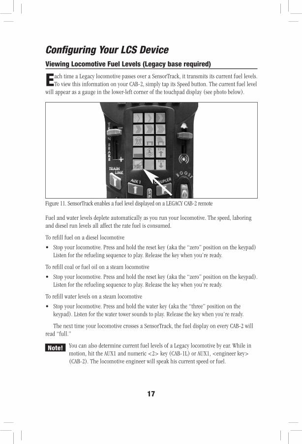
Viewing Locomotive Fuel Levels (Legacy base required)
Each time a Legacy locomotive passes over a SensorTrack, it transmits its current fuel levels. To view this information on your CAB-2, simply tap its Speed button. The current fuel level
will appear as a gauge in the lower-left corner of the touchpad display (see photo below).
Fuel and water levels deplete automatically as you run your locomotive. The speed, laboring and diesel run levels all affect the rate fuel is consumed.
To refill fuel on a diesel locomotive
• Stop your locomotive. Press and hold the reset key (aka the “zero” position on the keypad) Listen for the refueling sequence to play. Release the key when you’re ready.
To refill coal or fuel oil on a steam locomotive
• Stop your locomotive. Press and hold the reset key (aka the “zero” position on the keypad). Listen for the refueling sequence to play. Release the key when you’re ready.
To refill water levels on a steam locomotive
• Stop your locomotive. Press and hold the water key (aka the “three” position on the keypad). Listen for the water tower sounds to play. Release the key when you’re ready.
The next time your locomotive crosses a SensorTrack, the fuel display on every CAB-2 will read “full.”
You can also determine current fuel levels of a Legacy locomotive by ear. While in motion, hit the AUX1 and numeric <2> key (CAB-1L) or AUX1, <engineer key> (CAB-2). The locomotive engineer will speak his current speed or fuel.
Note!
Figure 11. SensorTrack enables a fuel level displayed on a LEGACY CAB-2 remote
Configuring Your LCS Device
18
Recording Actions on the LCS Sensor Track
In addition to the preset Action Commands, LCS SensorTrack can record custom commands defined by the operator. (Creating a recording turns off the current Action Command.) The
recordings you create begin when a locomotive rolls over a SensorTrack that is “armed” to record. From that moment, all commands are stored in the SensorTrack until you stop the recording. The next time a locomotive crosses the track, it plays back the previously recorded actions.
Here are some key recording concepts:
• Playback will be triggered by ANY passing compatible locomotive, unless you can create a recording that applies ONLY to one specific locomotive.
• Recordings include ALL commands sent by ANY OPERATOR to any locomotive, switch, accessory or other device. Alternately, you can create a recording which saves ONLY the commands sent to a specific list of devices.
• Each SensorTrack stores two recordings, one for “left-to-right” and one for “right-to-left.” If you want the same recording played in both directions, record the action twice.
• When multiple engines are part of a Train, only the head or front engine can trigger a user recording (or preset action command).
It is not necessary to erase a recording before creating a new one. Each time you create a recording, all commands that were part of a previous recording are automatically cleared.
Choosing a Recording Mode
SensorTrack has three different recording modes:
Mode 1 recordings will be played back by ALL passing compatible locomotives. Recording includes commands sent to ALL devices by ALL active operators.
Mode 2 recordings will be played back ONLY when the same locomotive used to create the recording passes over the SensorTrack. Mode 2 recordings include commands sent to ALL devices by ALL active operators.
Mode 3 recordings will be played back ONLY when the same locomotive used to create the recording passes over the SensorTrack. Mode 3 recordings include ONLY commands sent to the devices you specify before the recording starts.
Note!
19
MODE 1: Recordings that apply to ALL passing LEGACY locomotives
Mode 1 recordings will be played back by ANY passing compatible locomotive. Recording includes commands sent to ALL devices by ALL active operators.
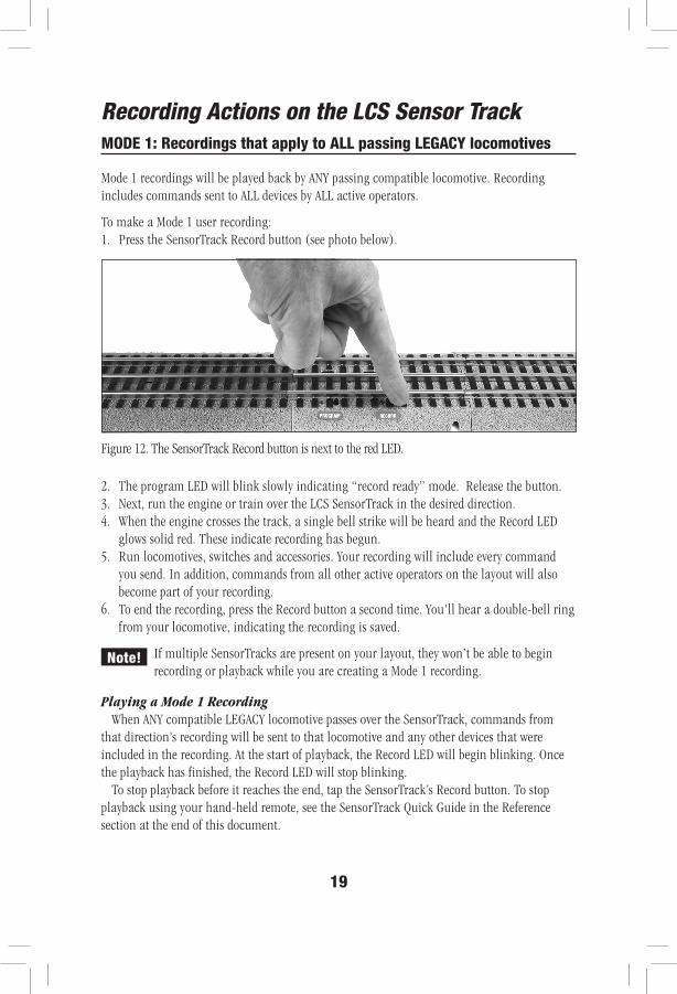
To make a Mode 1 user recording:1. Press the SensorTrack Record button (see photo below).
2. The program LED will blink slowly indicating “record ready” mode. Release the button.3. Next, run the engine or train over the LCS SensorTrack in the desired direction.4. When the engine crosses the track, a single bell strike will be heard and the Record LED
glows solid red. These indicate recording has begun. 5. Run locomotives, switches and accessories. Your recording will include every command
you send. In addition, commands from all other active operators on the layout will also become part of your recording.
6. To end the recording, press the Record button a second time. You'll hear a double-bell ring from your locomotive, indicating the recording is saved.
If multiple SensorTracks are present on your layout, they won’t be able to begin recording or playback while you are creating a Mode 1 recording.
Playing a Mode 1 RecordingWhen ANY compatible LEGACY locomotive passes over the SensorTrack, commands from
that direction’s recording will be sent to that locomotive and any other devices that were included in the recording. At the start of playback, the Record LED will begin blinking. Once the playback has finished, the Record LED will stop blinking.
To stop playback before it reaches the end, tap the SensorTrack’s Record button. To stop playback using your hand-held remote, see the SensorTrack Quick Guide in the Reference section at the end of this document.
Recording Actions on the LCS Sensor Track
Note!
Figure 12. The SensorTrack Record button is next to the red LED.
20
MODE 2: Recordings that play ONLY on one engine or train
Mode 2 recordings will be played back ONLY when the locomotive used to create the recording passes over the SensorTrack. Mode 2 recordings include commands sent to ALL devices by ALL active operators.
What can Mode 2 do that Mode 1 can’t? For example, every time your favorite passenger train approaches the station, your Mode 2 recording can throw a track switch to bring it into the station. But all other trains will stay on the mainline, bypassing the station.
To make a Mode 2 user recording:
1. Press the SensorTrack Record button. 2. The program LED will blink slowly indicating “record ready” mode. Release the button.3. Press the SET button on your remote. The Program LED will flicker. The next passing
Engine or Train ID will be the ONLY one that will trigger the playback of the recording we’re about to create.
4. Now, start the recording by running the locomotive over the LCS SensorTrack in the desired direction.
5. When the engine crosses the track, a single bell strike will be heard. This sound indicates recording has begun.
6. Run locomotives, switches and accessories. Your recording will include every command you send. In addition, commands from all other active operators on the layout will also become part of your recording.
7. To end the recording, press the SensorTrack Record button a second time. You'll hear a double-bell ring from your locomotive, indicating the recording is saved.
If multiple SensorTracks are present on your layout, they won’t be able to record or playback while you are creating a Mode 2 recording.
Playing a Mode 2 RecordingBring the locomotive used to create the recording back around and roll over the SensorTrack
again. That direction’s recording will be triggered and the locomotive will repeat the same behaviors of the original recording. No other locomotive will be able to trigger playback of this recording.
At the start of playback, the Record LED will begin blinking. Once the playback has finished, the Record LED will stop blinking. To stop playback before it reaches the end, tap the SensorTrack’s Record button. To stop playback using your hand-held remote, see the SensorTrack Quick Guide in the Reference section at the end of this document.
Recording Actions on the LCS Sensor Track
Note!
21
Recording ONLY the devices you specify (Mode 3)
Mode 3 is designed for recording during a busy operating session. Using this mode, you can make a recording while others continue to operate their locomotives, switches and accessories—but ONLY commands sent to devices you specify will be added to your recording. Commands sent by other operators are not recorded. You must specify this list of devices before the recording starts.
During a Mode 3 recording, other SensorTracks on the layout will operate normally (their operations are suppressed when recording in Mode 1 and Mode 2).
To make a recording that will apply to only to ONE passing LEGACY locomotive and includes ONLY commands sent to devices you specify in advance:
1. Press the SensorTrack Record button. 2. The program LED will blink slowly indicating “record ready” mode. Release the button.3. Press the SET button on your remote. The Program LED will flicker. The next passing Engine
or Train ID will be coded as the ONLY one which will trigger the playback of the recording we’re about to create.
4. Press ENGINE, TRAIN, SWITCH or ACCESSORY on your remote followed the TMCC ID number of that device which you want to include in the recording.
5. Press SET on your remote. The Program LED will flicker.
Repeat steps 3 and 4 for every device you wish to be included in your recording.
6. Now, start the recording by running the locomotive over the LCS SensorTrack in the desired direction.
7. When the engine crosses the track, a single bell strike will be heard. This sound indicates recording has begun.
8. From this point, all commands sent by the remote to the engine or train ID of the passing locomotive are recorded. In addition, commands sent to the devices you specified in steps 4-5 will also be included as part of your Custom Recording. No other commands will be recorded.
9. To end the recording, press the SensorTrack Record button a second time. You'll hear a double-bell ring from your locomotive, indicating the recording is saved.
Playing a Mode 3 RecordingBring the locomotive used to create the recording back around and roll over the SensorTrack again.
That direction’s recording will be triggered and the locomotive will repeat the same behaviors of the original recording. No other locomotive will be able to trigger playback of this recording.
At the start of playback, the Record LED will begin blinking slowly. Once the playback has finished, the Record LED will stop blinking. To stop playback before it reaches the end, tap the SensorTrack’s Record button. To stop playback using your hand-held remote, see the SensorTrack Quick Guide in the Reference section at the end of this document.
Recording Actions on the LCS Sensor Track
Note!
22
Erasing or Disabling Recordings
To erase recordings in both directions:
1. Press and hold the SensorTrack Record button until it begins to flash2. Release the button for a moment.3. Press and hold the SensorTrack Record button again, until it glows solid red.4. Release the button. The recordings stored for both directions have been deleted.
To disable playback (but not erase) your custom recordings on one SensorTrack:
1. Press and hold the SensorTrack Program button until it begins to flash 2. On your Lionel remote, press ACC3. Enter the two digit TMCC ID. For ID’s 1-9, enter a leading zero (eg. “02, 03,” etc.)4. Press the SET key5. Press AUX1 and the digit zero.
To enable playback of your last pair of custom recordings on one SensorTrack:
1. Press and hold the SensorTrack Program button until it begins to flash 2. On your Lionel remote, press ACC3. Enter the two digit TMCC ID. For ID’s 1-9, enter a leading zero (eg. “02, 03,” etc.)4. Press the SET key5. Press AUX1 and the digit 9.
Recording when you have more than one SensorTrack
If you have more than one SensorTrack, recording using Mode 1 or Mode 2 will inhibit the other SensorTrack(s) on your layout as follows:
• Triggering of preset action commands will be suppressed• Triggering of custom recordings will be suppressed• A track that was in “record-ready” mode (blinking Record LED) will exit record-ready
mode.
However, creating a Mode 3 recording on one SensorTrack has no effect on other SensorTracks, they will continue to operate normally.
Recording Actions on the LCS Sensor Track
23
Creating Complex Recordings
It is possible to create quite complicated recordings that play back over time. Here are a few tips to help you get the most out of this feature—and avoid frustration!
If your recording is long, it’s possible your locomotive could make a full lap, rolling over SensorTrack before playback has finished. Don’t worry, the second roll-over is ignored. However, if a different locomotive rolls over a SensorTrack while it is still playing commands to an earlier locomotive, an additional copy of the recording will begin playing. In fact, up to five different locomotives can simultaneously be controlled by a single SensorTrack. The actions of each will be offset in time by an amount equal to the duration between their initial roll-overs.
Next, is the exact position of the locomotive an important part of your recording? (example: stopping in front of a station). Repeatable stops at a particular location require your engine be traveling at the same exact speed when triggering playback as its speed at the start of the recording. The longer your recording goes, the greater the “error” or difference in location between the recording and playback will be.
To address this issue, CAB-2 users should send their desired preset speed command before recording and again before playback. This ensures the loco speed is the same each time it crosses the track. Similarly, it may be helpful to set the desired momentum value before recording and again before playback, since momentum affects how quickly your engine responds to speed changes.
How many commands fit in a recording?A recording in each direction can include a couple hundred commands or more, depending
on their type and spacing (note that each time you hold a whistle blow or spin the throttle, multiple commands are generated). If the recording buffer becomes full before you end the recording yourself, SensorTrack stops the recording automatically. You’ll hear the “ding-ding” from the triggering locomotive, indicating no further commands will be recorded.
How many minutes can my recording last?Your recording can last just a second, or run for many minutes, or longer—until you
fill up the available recording space. Long time gaps between commands do not “use up” memory space. However, if more than five-and-a-half minutes elapses since the last command was received, SensorTrack assumes you have forgotten about this recording and it will be automatically ended. You’ll hear the “ding-ding” from the triggering locomotive, indicating no further commands are being recorded.
Recording Actions on the LCS Sensor Track

24
SensorTrack and the LCS iPad App
SensorTrack can also send information to an iPad or other computing device connected to the LCS system on your layout. If you’re using Lionel’s LCS App, the location of
each passing Legacy locomotive will appear on your iPad screen, next to its corresponding SensorTrack icon.
In order for this feature to work, you must add a SensorTrack icon to one or more of your LCS App custom control panels. Then, be sure to apply the same TMCC ID to the physical SensorTrack as well as the virtual SensorTrack on your iPad.
Refer to the on-line help system of LCS App for more information.
Note!
25
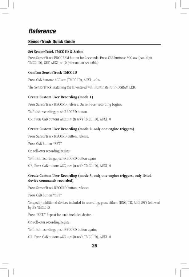
ReferenceSensorTrack Quick Guide
Set SensorTrack TMCC ID & Action
Press SensorTrack PROGRAM button for 2 seconds. Press CAB buttons: ACC nn (two-digit TMCC ID), SET, AUX1, n (0-9 for action-see table)
Confirm SensorTrack TMCC ID
Press CAB buttons: ACC nn (TMCC ID), AUX1, <0>.
The SensorTrack matching the ID entered will illuminate its PROGRAM LED.
Create Custom User Recording (mode 1)
Press SensorTrack RECORD, release. On roll-over recording begins.
To finish recording, push RECORD button
OR, Press CAB buttons ACC, nn (track’s TMCC ID), AUX1, 0
Create Custom User Recording (mode 2, only one engine triggers)
Press SensorTrack RECORD button, release.
Press CAB Button “SET”
On roll-over recording begins.
To finish recording, push RECORD button again
OR, Press CAB buttons ACC, nn (track’s TMCC ID), AUX1, 0
Create Custom User Recording (mode 3, only one engine triggers, only listed device commands recorded)
Press SensorTrack RECORD button, release.
Press CAB Button “SET”
To specify additional devices included in recording, press either: (ENG, TR, ACC, SW) followed by it’s TMCC ID
Press “SET.” Repeat for each included device.
On roll-over recording begins.
To finish recording, push RECORD button again,
OR, Press CAB buttons ACC, nn (track’s TMCC ID), AUX1, 0
26
SensorTrack Quick Guide (continued)
Terminate Currently playing User RecordingWhile a recording is playing back press and release the RECORD button, OR, Press CAB buttons ACC, nn (track’s TMCC ID), AUX1, 0The currently playing recording is terminated, but can be triggered again.
Erase User Recordings (both directions)Press and hold Record button on a SensorTrack until it starts blinking.Release recording buttonPress and hold Record button until is glows solid red. Release. User recordings on that track
are now deleted.
SLEEP One SensorTrack Press and hold PROGRAM and RECORD for 2 seconds. Both LEDs flicker and go off when buttons are released. This SensorTrack will:
• no longer play preset actions or user recordings when locomotives roll-over, • terminate a currently playing user recording, • exit record-armed or program mode if active.
SLEEP ALL SensorTracks Press CAB buttons ACC, 99, AUX1, 0
Wake One SensorTrack Press and hold PROGRAM and RECORD for 2 seconds. Both LEDs turn on until buttons are released.When you WAKE a SensorTrack, all normal operation is restored, but activities interrupted by
SLEEP are not resumed—they must be re-triggered.
Wake ALL SensorTracks Press CAB buttons ACC, 99, AUX1, 1
To Disable Legacy Base updates on ALL SensorTracksPress CAB buttons ACC, 99, AUX1, 3
To Enable Legacy Base updates on ALL SensorTracksPress CAB buttons ACC, 99, AUX1, 4
Reference
27
Operation of LEDs
On power up, both LEDs on your SensorTrack will turn on for 1 second. If the Red LED remains on continuously, this indicates a problem with the PDI cabling or your command base.
Program LED:• Illuminates when receiving data from locomotive.• Flashing: track is in Program mode.• Flicker in program mode: Acknowledge command received.
Record LED• Flashing: SensorTrack is “record-armed,” and will start recording when compatible
locomotive crosses over. During recording, Record LED is on continuously.• Slow blinking: Track is currently playing a custom user recording.
Specifications of the LCS SensorTrack
Physical Ratings
• Size: 5” FasTrack straight section
Power Budget
• Input PDI supply current: 15 mA
Reference
©2014 LIONEL L.L.C., CONCORD, NC 28027UNITED STATES OF AMERICAPRINTED IN CHINA
Lionel Limited Warranty Policy & Service
This Lionel product, including all mechanical and electrical components, moving parts, motors and structural components, with the exception of LIGHT BULBS, LED’s & TRACTION TIRES are warranted to the original owner-purchaser for a period of one
year from the original date of purchase against original defects in materials or workmanship when purchased through a Lionel Authorized Retailer*.
This warranty does NOT cover the following:• Normal wear and tear• Light bulbs or LED’s• Defects appearing in the course of commercial use• Damage resulting from abuse/misuse of the product
Transfer of this product by the original owner-purchaser to another person voids this warranty in its entirety. Modification of this product in any way; visually mechanically or electronically, voids the warranty in its entirety.
Any warranted product which is defective in original materials or workmanship and is delivered by the original owner-purchaser (this warranty is non-transferrable) to Lionel LLC or any Lionel Authorized Service Station MUST be accompanied by the original receipt for purchase (or copy) from an Authorized Lionel Retailer*, will at the discretion of Lionel LLC, be repaired or replaced, without charge for parts or labor. In the event the defective product cannot be repaired, and a suitable replacement is not available, Lionel will offer to replace the product with a comparable model (determined by Lionel LLC), if available. In the event a comparable model is not available the customer will be refunded the original purchase price (requires proof of purchase from the Authorized Lionel Retailer* it was originally purchased). Any products on which warranty service is sought must be sent freight or postage prepaid (Lionel will refuse any package when postage is due). Transportation and shipping charges are not covered as part of this warranty.
NOTE: Products that require service that do not have a receipt from an LIONEL AUTHORIZED RETAILER* will be required to pay for all parts required to repair the product (labor will not incur a charge) providing the product is not older than 3 years from date of manufacture and is within 1 year from date of purchase. A copy of the original sales receipt is required.In no event shall Lionel LLC be held liable for incidental or consequential damages. Some states do not allow the exclusion or limitation of incidental or consequential damages, so the above exclusion may not apply to you. This warranty gives you specific legal rights and you may have other rights which vary from state to state.
Instructions for Obtaining Service If service for this Lionel LLC product is required; bring the item, along with your DATED sales receipt and completed warranty information (at the bottom of this page) to the nearest Lionel Authorized Service Station. Your nearest Lionel Service Station can be found by calling 1-800-4-LIONEL or by accessing the website at www.lionel.com.
If you prefer to send your Lionel product directly to Lionel, for repair you must FIRST call 586-949-4100 extension 2 or FAX Lionel at 330-286-4146 or write to Lionel Customer Service, 6655 Seville Drive, Canfield, OH 44406. Please have the 6-digit Lionel product number, the date of original purchase, the dealer where the item was purchased and what seems to be the problem. You will receive a return authorization (RA) number to ensure your merchandise will be properly tracked and handled upon receipt at Lionel LLC.
Once you have your Return Authorization (RA) number, make sure the item is packed in its original Styrofoam inner container which is placed inside the original outer display box (this will help prevent damage during shipping and handling). This shipment MUST be prepaid and we recommend that it be insured with the carrier of your choice.
Please make sure you have followed all of the above instructions carefully before returning any merchandise for service. You may choose to have your product repaired by one of Lionel LLC’s Authorized Service Stations after its warranty has expired. A reasonable service fee should be expected once the product warranty has expired.Warranty Information Please complete the information below and keep it, along with your DATED ORIGINAL SALES RECEIPT. You MUST present this form AND your DATED SALES RECEIPT when requesting warranty service.
*A complete listing of Lionel Authorized retailers can be found by calling 1-800-4-LIONEL or by visiting our website at www.lionel.com.
Products that are more than 3 years old, from date of manufacture, are not applicable for warranty coverage, even if they have never been sold prior to this date. (Under no circumstance shall any components or labor be provided free of charge.)
Name _________________________________________________________________________Address ________________________________________________________________________Place of Purchase _________________________________________________________________Date of Purchase __________________________________________________________________Product Number __________________________________________________________________Product Description ________________________________________________________________