Embed Size (px)
Citation preview
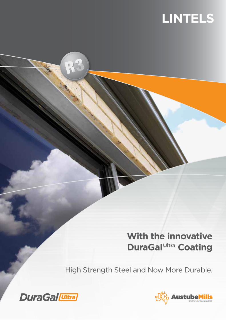
With the innovative DuraGalUltra Coating
High Strength Steel and Now More Durable.
LINTELS
2
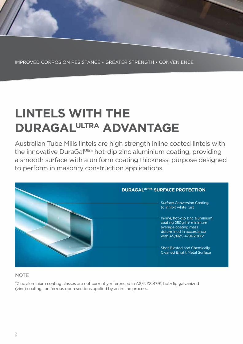
LINTELS WITH THE DURAGALULTRA ADVANTAGEAustralian Tube Mills lintels are high strength inline coated lintels with the innovative DuraGalUltra hot-dip zinc aluminium coating, providing a smooth surface with a uniform coating thickness, purpose designed to perform in masonry construction applications.
NOTE
*Zinc aluminium coating classes are not currently referenced in AS/NZS 4791, hot-dip galvanized (zinc) coatings on ferrous open sections applied by an in-line process.
DURAGALULTRA SURFACE PROTECTION
In-line, hot-dip zinc aluminium coating 250g/m2 minimum average coating mass determined in accordance with AS/NZS 4791-2006*
Shot Blasted and Chemically Cleaned Bright Metal Surface
Surface Conversion Coating to inhibit white rust
IMPROVED CORROSION RESISTANCE • GREATER STRENGTH • CONVENIENCE
3
DURAGALULTRA TESTING
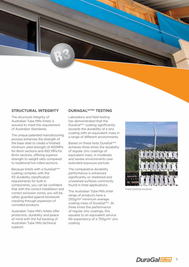
Laboratory and field testing has demonstrated that the DuraGalUltra coating significantly exceeds the durability of a zinc coating with an equivalent mass in a range of different environments.
Based on these tests DuraGalUltra achieves three times the durability of regular zinc coatings of equivalent mass, in moderate and severe environments over extended exposure periods.
The comparative durability performance is enhanced significantly on sheltered and unwashed surfaces commonly found in lintel applications.
The Australian Tube Mills lintel range of products have a 250g/m2 minimum average coating mass of DuraGalUltra. At three times the performance of regular zinc coatings, this equates to an equivalent service life expectancy of a 750g/m2 zinc coating.
STRUCTURAL INTEGRITY
The structural integrity of Australian Tube Mills lintels is assured to meet the requirement of Australian Standards.
The unique patented manufacturing process enhances the strength of the base steel to create a finished minimum yield strength of 400MPa for 8mm sections and 450 MPa for 6mm sections, offering superior strength to weight ratio compared to traditional hot rolled sections.
Because lintels with a DuraGalUltra coating complies with the R3 durability classification requirements for built in components, you can be confident that with the correct installation and correct exclusion zones, you will be safely guarded against brickwork cracking through expansion of corroded products.
Australian Tube Mill’s lintels offer protection, durability and peace of mind with the full backing of Australian Tube Mills technical support.
Field testing location
4
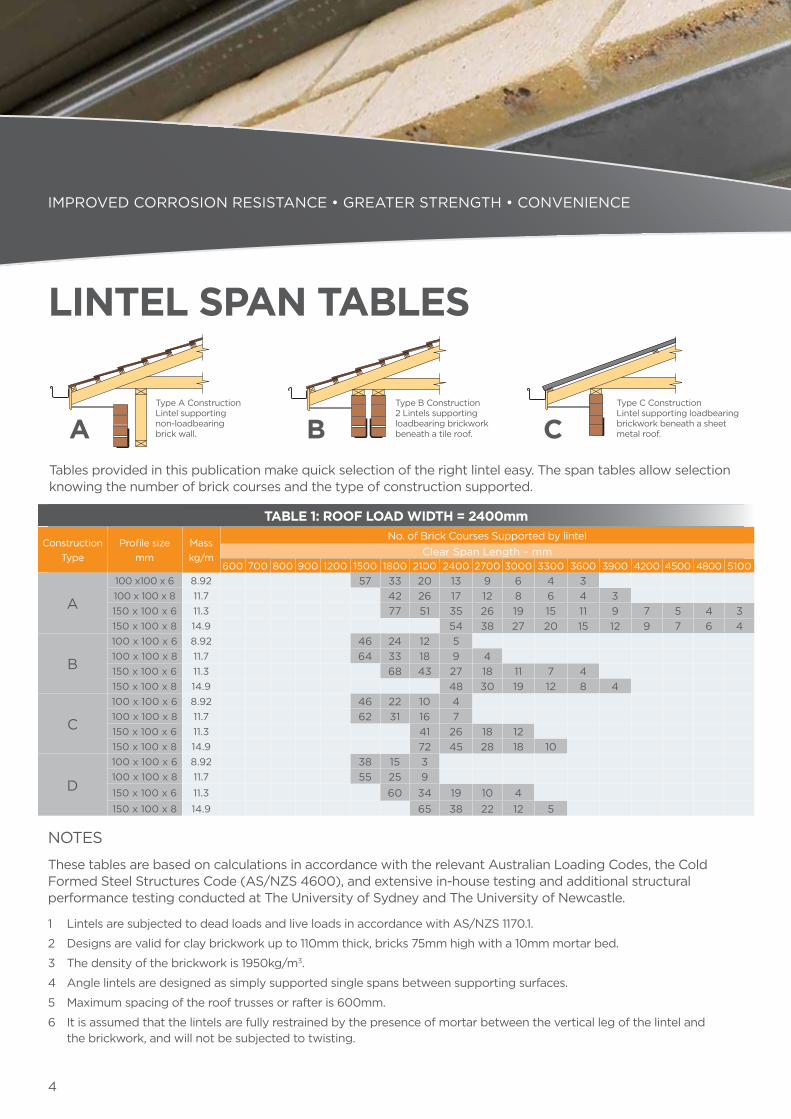
TABLE 1: ROOF LOAD WIDTH = 2400mm
Construction Type
Profile size mm
Mass kg/m
No. of Brick Courses Supported by lintelClear Span Length – mm
600 700 800 900 1200 1500 1800 2100 2400 2700 3000 3300 3600 3900 4200 4500 4800 5100
A
100 x100 x 6 8.92 57 33 20 13 9 6 4 3100 x 100 x 8 11.7 42 26 17 12 8 6 4 3150 x 100 x 6 11.3 77 51 35 26 19 15 11 9 7 5 4 3150 x 100 x 8 14.9 54 38 27 20 15 12 9 7 6 4
B
100 x 100 x 6 8.92 46 24 12 5100 x 100 x 8 11.7 64 33 18 9 4150 x 100 x 6 11.3 68 43 27 18 11 7 4150 x 100 x 8 14.9 48 30 19 12 8 4
C
100 x 100 x 6 8.92 46 22 10 4100 x 100 x 8 11.7 62 31 16 7150 x 100 x 6 11.3 41 26 18 12150 x 100 x 8 14.9 72 45 28 18 10
D
100 x 100 x 6 8.92 38 15 3100 x 100 x 8 11.7 55 25 9150 x 100 x 6 11.3 60 34 19 10 4150 x 100 x 8 14.9 65 38 22 12 5
Type A Construction Lintel supporting non-loadbearing brick wall.A
Type B Construction 2 Lintels supporting loadbearing brickwork beneath a tile roof.B
Type C Construction Lintel supporting loadbearing brickwork beneath a sheet metal roof.C
Tables provided in this publication make quick selection of the right lintel easy. The span tables allow selection knowing the number of brick courses and the type of construction supported.
IMPROVED CORROSION RESISTANCE • GREATER STRENGTH • CONVENIENCE
NOTES
These tables are based on calculations in accordance with the relevant Australian Loading Codes, the Cold Formed Steel Structures Code (AS/NZS 4600), and extensive in-house testing and additional structural performance testing conducted at The University of Sydney and The University of Newcastle.
1 Lintels are subjected to dead loads and live loads in accordance with AS/NZS 1170.1.
2 Designs are valid for clay brickwork up to 110mm thick, bricks 75mm high with a 10mm mortar bed.
3 The density of the brickwork is 1950kg/m3.
4 Angle lintels are designed as simply supported single spans between supporting surfaces.
5 Maximum spacing of the roof trusses or rafter is 600mm.
6 It is assumed that the lintels are fully restrained by the presence of mortar between the vertical leg of the lintel and the brickwork, and will not be subjected to twisting.
LINTEL SPAN TABLES
5
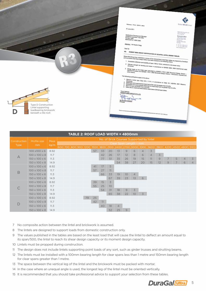
TABLE 2: ROOF LOAD WIDTH = 4800mm
Construction Type
Profile size mm
Mass kg/m
No. of Brick Courses Supported by lintelClear Span Length – mm
600 700 800 900 1200 1500 1800 2100 2400 2700 3000 3300 3600 3900 4200 4500 4800 5100
A
100 x100 x 6 8.92 57 33 20 13 9 6 4 3100 x 100 x 8 11.7 42 26 17 12 8 6 4 3150 x 100 x 6 11.3 77 51 35 26 19 15 11 9 7 5 4 3150 x 100 x 8 14.9 54 38 27 20 15 12 9 7 6 4
B
100 x 100 x 6 8.92 41 17 5100 x 100 x 8 11.7 57 27 11150 x 100 x 6 11.3 66 33 19 10 4150 x 100 x 8 14.9 67 39 23 13 6
C
100 x 100 x 6 8.92 39 15 3100 x 100 x 8 11.7 55 25 10150 x 100 x 6 11.3 54 31 18 9 3150 x 100 x 8 14.9 65 38 22 10 3
D
100 x 100 x 6 8.92 79 25100 x 100 x 8 11.7 42 11150 x 100 x 6 11.3 40 18 4150 x 100 x 8 14.9 52 25 9
Type D Construction Lintel supporting loadbearing brickwork beneath a tile roof.D
7 No composite action between the lintel and brickwork is assumed.
8 The lintels are designed to support loads from domestic construction only.
9 The values published in the tables are based on the least load that will cause the lintel to deflect an amount equal to its span/500, the lintel to reach its shear design capacity or its moment design capacity.
10 Lintels must be propped during construction.
11 The design does not include lintels supporting point loads of any sort, such as girder trusses and strutting beams.
12 The lintels must be installed with a 100mm bearing length for clear spans less than 1 metre and 150mm bearing length for clear spans greater than 1 metre.
13 The space between the vertical leg of the lintel and the brickwork must be packed with mortar.
14 In the case where an unequal angle is used, the longest leg of the lintel must be oriented vertically.
15 It is recommended that you should take professional advice to support your selection from these tables.
6
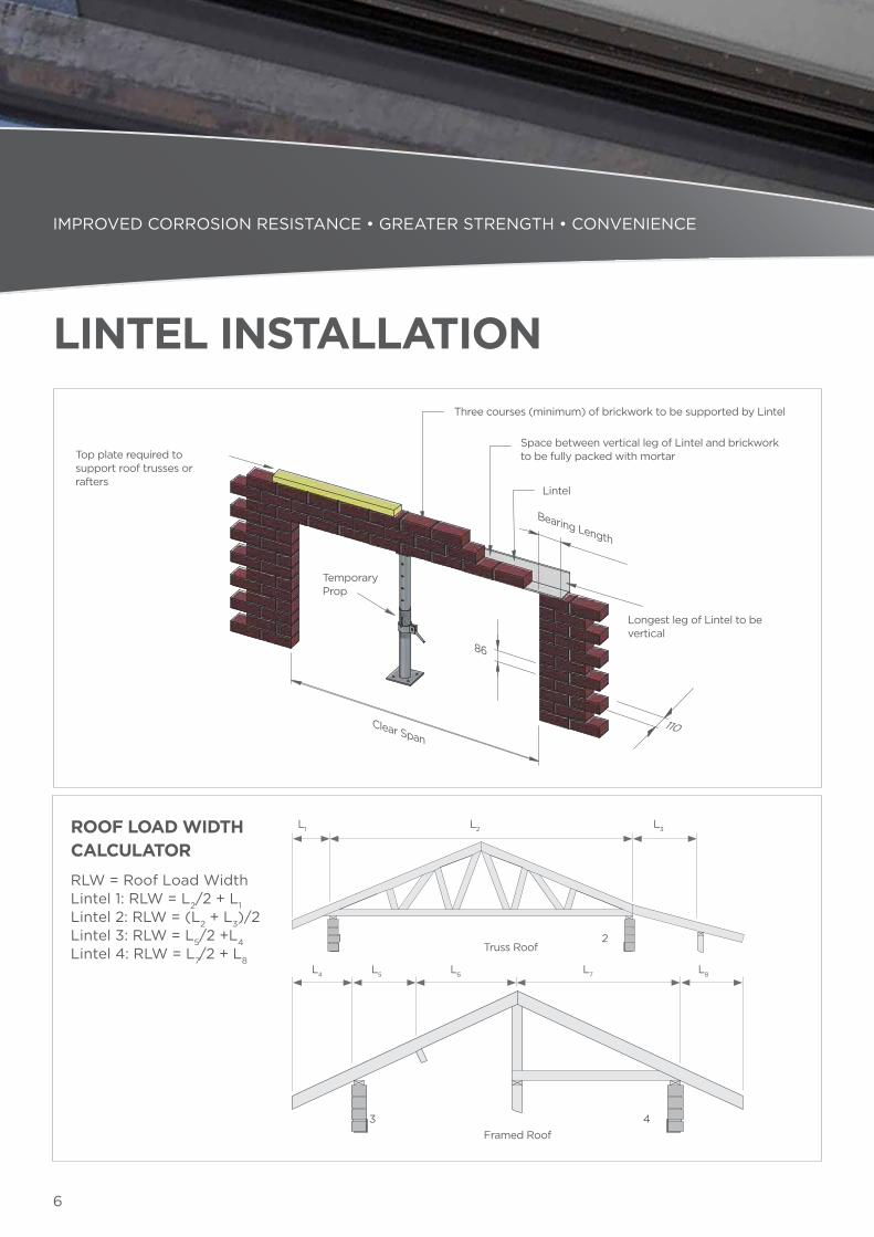
ROOF LOAD WIDTH CALCULATOR
RLW = Roof Load Width Lintel 1: RLW = L2/2 + L1 Lintel 2: RLW = (L2 + L3)/2 Lintel 3: RLW = L5/2 +L4 Lintel 4: RLW = L7/2 + L8
Truss Roof
L1
L4 L5 L6 L7 L8
L2 L3
Framed Roof
1
3 4
2
Three courses (minimum) of brickwork to be supported by Lintel
Top plate required to support roof trusses or rafters
Longest leg of Lintel to be vertical
110Clear Span
86
Bearing Length
Lintel
Temporary Prop
Space between vertical leg of Lintel and brickwork to be fully packed with mortar
IMPROVED CORROSION RESISTANCE • GREATER STRENGTH • CONVENIENCE
LINTEL INSTALLATION
7
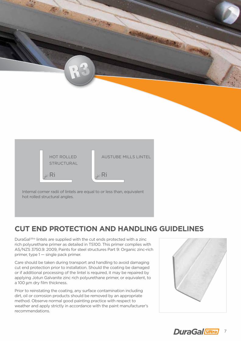
DuraGalUltra lintels are supplied with the cut ends protected with a zinc rich polyurethane primer as detailed in TS100. This primer complies with AS/NZS 3750.9: 2009, Paints for steel structures Part 9: Organic zinc-rich primer, type 1 — single pack primer.
Care should be taken during transport and handling to avoid damaging cut end protection prior to installation. Should the coating be damaged or if additional processing of the lintel is required, it may be repaired by applying Jotun Galvanite zinc rich polyurethane primer, or equivalent, to a 100 μm dry film thickness.
Prior to reinstating the coating, any surface contamination including dirt, oil or corrosion products should be removed by an appropriate method. Observe normal good painting practice with respect to weather and apply strictly in accordance with the paint manufacturer’s recommendations.
CUT END PROTECTION AND HANDLING GUIDELINES
Internal corner radii of lintels are equal to or less than, equivalent hot rolled structural angles.
Ri
AUSTUBE MILLS LINTEL
Ri
HOT ROLLED
STRUCTURAL
8
IMPROVED CORROSION RESISTANCE • GREATER STRENGTH • CONVENIENCE
NOTES
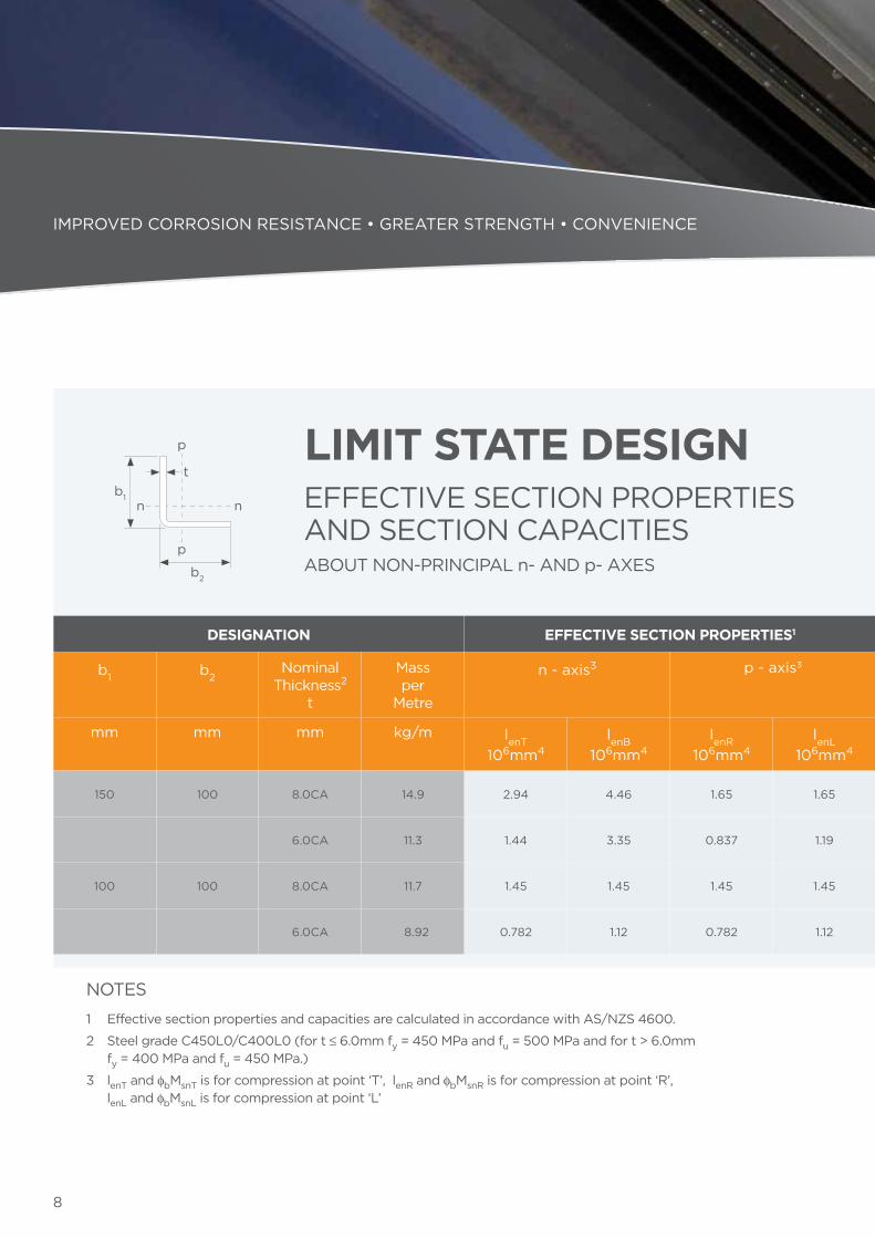
1 Effective section properties and capacities are calculated in accordance with AS/NZS 4600.
2 Steel grade C450L0/C400L0 (for t ≤ 6.0mm fy = 450 MPa and fu = 500 MPa and for t > 6.0mm fy = 400 MPa and fu = 450 MPa.)
3 lenT and fbMsnT is for compression at point ‘T’, lenR and fbMsnR is for compression at point ‘R’, lenL and fbMsnL is for compression at point ‘L’
b1
b2
p
p
nn
tLIMIT STATE DESIGN
DESIGNATION EFFECTIVE SECTION PROPERTIES1 SECTION CAPACITIES1
b1 b2Nominal
Thickness2
t
Massper
Metre
n - axis3 p - axis3 Axial Tension4
Axial Compression
Moment Shear
n - axis3 p - axis3 n - axis5 p - axis5
mm mm mm kg/m lenT106mm4
lenB106mm4
lenR106mm4
lenL106mm4
ftNtkN
fcNskN
fbMsnTkNm
fbMsnBkNm
fbMspRkNm
fbMspLkNm
fvVvnkN
fvVvnkN
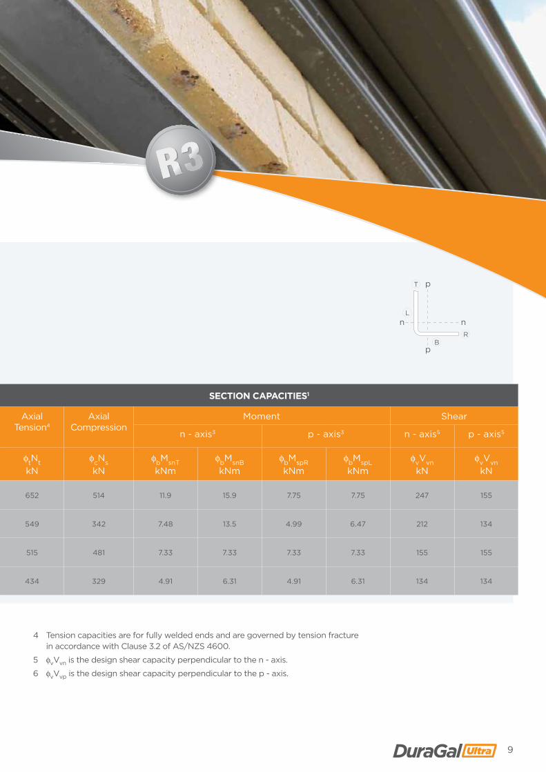
150 100 8.0CA 14.9 2.94 4.46 1.65 1.65 652 514 11.9 15.9 7.75 7.75 247 155
6.0CA 11.3 1.44 3.35 0.837 1.19 549 342 7.48 13.5 4.99 6.47 212 134
100 100 8.0CA 11.7 1.45 1.45 1.45 1.45 515 481 7.33 7.33 7.33 7.33 155 155
6.0CA 8.92 0.782 1.12 0.782 1.12 434 329 4.91 6.31 4.91 6.31 134 134
EFFECTIVE SECTION PROPERTIES AND SECTION CAPACITIESABOUT NON-PRINCIPAL n- AND p- AXES
9
p
p
nn
T
RB
L
4 Tension capacities are for fully welded ends and are governed by tension fracture in accordance with Clause 3.2 of AS/NZS 4600.
5 fvVvn is the design shear capacity perpendicular to the n - axis.
6 fvVvp is the design shear capacity perpendicular to the p - axis.
DESIGNATION EFFECTIVE SECTION PROPERTIES1 SECTION CAPACITIES1
b1 b2Nominal
Thickness2
t
Massper
Metre
n - axis3 p - axis3 Axial Tension4
Axial Compression
Moment Shear
n - axis3 p - axis3 n - axis5 p - axis5
mm mm mm kg/m lenT106mm4
lenB106mm4
lenR106mm4
lenL106mm4
ftNtkN
fcNskN
fbMsnTkNm
fbMsnBkNm
fbMspRkNm
fbMspLkNm
fvVvnkN
fvVvnkN
150 100 8.0CA 14.9 2.94 4.46 1.65 1.65 652 514 11.9 15.9 7.75 7.75 247 155
6.0CA 11.3 1.44 3.35 0.837 1.19 549 342 7.48 13.5 4.99 6.47 212 134
100 100 8.0CA 11.7 1.45 1.45 1.45 1.45 515 481 7.33 7.33 7.33 7.33 155 155
6.0CA 8.92 0.782 1.12 0.782 1.12 434 329 4.91 6.31 4.91 6.31 134 134
10
IMPROVED CORROSION RESISTANCE • GREATER STRENGTH • CONVENIENCE
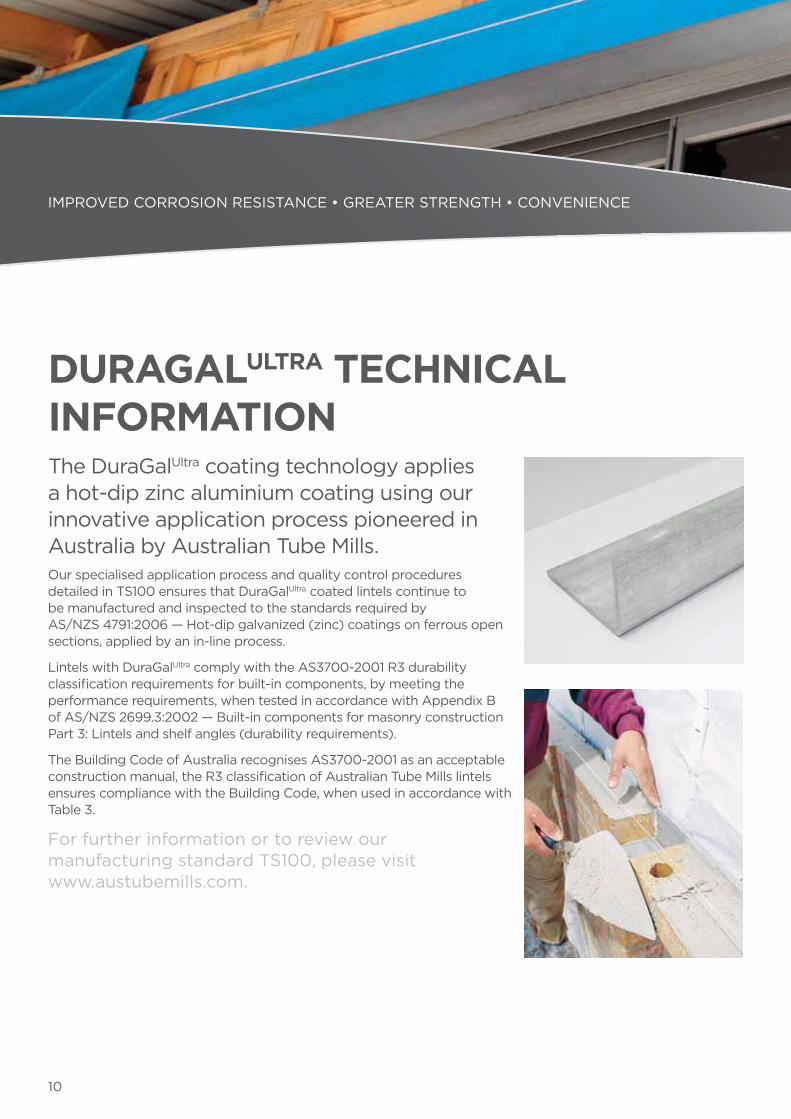
The DuraGalUltra coating technology applies a hot-dip zinc aluminium coating using our innovative application process pioneered in Australia by Australian Tube Mills. Our specialised application process and quality control procedures detailed in TS100 ensures that DuraGalUltra coated lintels continue to be manufactured and inspected to the standards required by AS/NZS 4791:2006 — Hot-dip galvanized (zinc) coatings on ferrous open sections, applied by an in-line process.
Lintels with DuraGalUltra comply with the AS3700-2001 R3 durability classification requirements for built-in components, by meeting the performance requirements, when tested in accordance with Appendix B of AS/NZS 2699.3:2002 — Built-in components for masonry construction Part 3: Lintels and shelf angles (durability requirements).
The Building Code of Australia recognises AS3700-2001 as an acceptable construction manual, the R3 classification of Australian Tube Mills lintels ensures compliance with the Building Code, when used in accordance with Table 3.
For further information or to review our manufacturing standard TS100, please visit www.austubemills.com.
DURAGALULTRA TECHNICAL INFORMATION
11
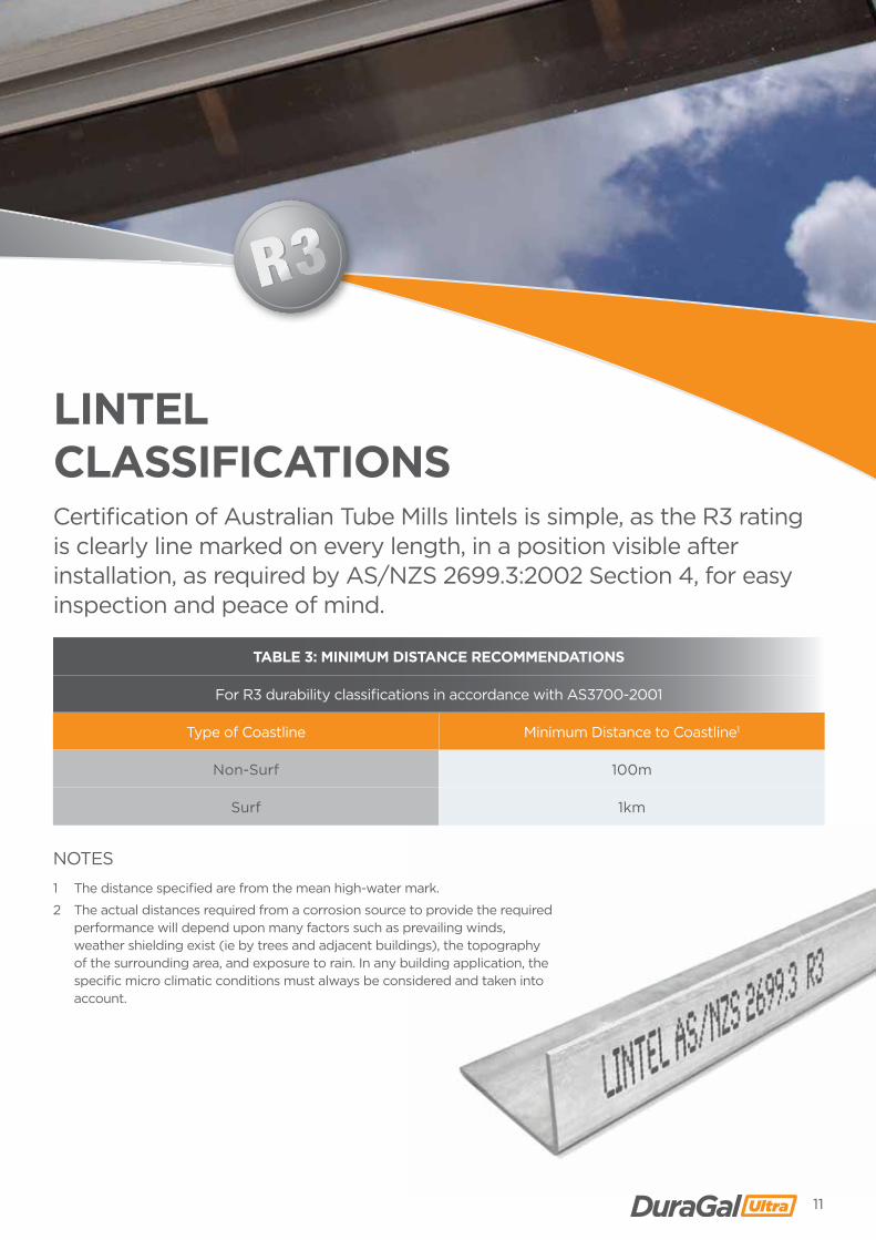
Certification of Australian Tube Mills lintels is simple, as the R3 rating is clearly line marked on every length, in a position visible after installation, as required by AS/NZS 2699.3:2002 Section 4, for easy inspection and peace of mind.
NOTES
1 The distance specified are from the mean high-water mark.
2 The actual distances required from a corrosion source to provide the required performance will depend upon many factors such as prevailing winds, weather shielding exist (ie by trees and adjacent buildings), the topography of the surrounding area, and exposure to rain. In any building application, the specific micro climatic conditions must always be considered and taken into account.
TABLE 3: MINIMUM DISTANCE RECOMMENDATIONS
For R3 durability classifications in accordance with AS3700-2001
Type of Coastline Minimum Distance to Coastline1
Non-Surf 100m
Surf 1km
LINTEL CLASSIFICATIONS
Australian Tube Mills 146 Ingram Road, Acacia Ridge
Queensland 4110 AustraliaPO Box 246, Sunnybank
Queensland 4109 AustraliaPhone: +61 7 3909 6600
Fax: +61 7 3909 6660www.austubemills.com
DISTRIBUTED BY
This publication has been prepared as a guide only to assist anyone that may specify or use the products described in this publication. Accordingly, while Australian Tube Mills has endeavoured to ensure that all information provided in this publication is accurate and up-to-date, the following must be noted: this publication does not take into account any individual circumstances and is therefore not a substitute for informed or professional individual advice; the specifications and technical data relating to the products described in this publication are approximate and subject to change without notice, and users should check the currency of the information before relying upon it; and unless required by law, Australian Tube Mills does not accept any responsibility for any loss, damage or consequence resulting from the contents of this publication or from any omission of information in this publication. © Copyright Australian Tube Mills Pty Ltd. DuraGalUltra is a registered trade mark of Australian Tube Mills Pty Ltd. August 2013.