Embed Size (px)
Citation preview

45 b 1cr
RA 83 100.1
Linear Bushings and Shafts
Linear Motion andAssembly Technologies
2 RA 83 100.1
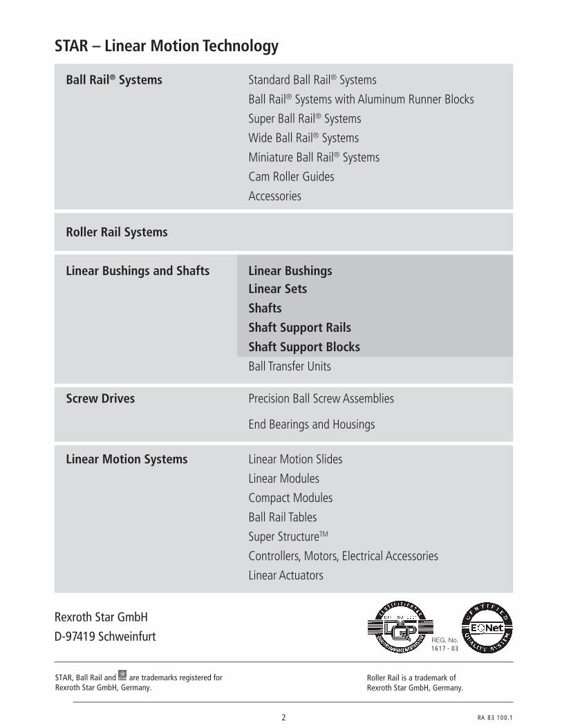
STAR – Linear Motion Technology
REG. No.1617 - 03
Rexroth Star GmbH
D-97419 Schweinfurt
Roller Rail is a trademark ofRexroth Star GmbH, Germany.
STAR, Ball Rail and are trademarks registered forRexroth Star GmbH, Germany.
Ball Rail® Systems Standard Ball Rail® Systems
Ball Rail® Systems with Aluminum Runner Blocks
Super Ball Rail® Systems
Wide Ball Rail® Systems
Miniature Ball Rail® Systems
Cam Roller Guides
Accessories
Roller Rail Systems
Linear Bushings and Shafts Linear BushingsLinear Sets
Shafts
Shaft Support Rails
Shaft Support Blocks
Ball Transfer Units
Screw Drives Precision Ball Screw Assemblies
End Bearings and Housings
Linear Motion Systems Linear Motion Slides
Linear Modules
Compact Modules
Ball Rail Tables
Super StructureTM
Controllers, Motors, Electrical Accessories
Linear Actuators

RA 83 100.1 3
Linear Bushings and Shafts
are trade marks registered forRexroth Star GmbH, Germany.
STAR Linear Bushing,STAR Super Linear Bushing,STAR Radial Linear Bushing,
STAR Linear Set andSTAR Radial Set
, STAR,
Product Overview 4
General Technical Data andMounting Instructions 12
Standard Linear Bushings 26Linear Sets with Standard Linear Bushings 40
Super Linear Bushings and 50Linear Sets with Super Linear Bushings and 66
Super Linear Bushings and 88Linear Sets with Super Linear Bushings and 104
Compact Linear Bushings 112Compact Linear Sets 118
Segmental Linear Bushings 120Linear Sets with Segmental Linear Bushings 126
Radial Linear Bushings 128Linear Sets with Radial Linear Bushings 136Radial Compact Sets 140
Torque-Resistant Linear Bushings 146Torque-Resistant Compact Linear Bushings 154Linear Sets with Torque-Resistant Linear Bushings 156
Linear Bushings for Combined Linear and Rotary Motion 174
Precision Steel Shafts 178
Shaft Support Rails 198
Shaft Support Blocks 224

4 RA 83 100.1
Linear Bushingsfor CombinedLinear andRotary Motion
26
50
88
88
112
120
128
146
174
- closed/adjustable/open- without/with internal wiper
seals- STAR Resist
(zinc-iron coating)
- closed/open- with internal wiper seals/
separate seals
- closed/open- without/with internal
wiper seals/fully sealed- STAR Resist
(zinc-iron coating)
- closed/open- without/with internal
wiper seals/fully sealed- STAR Resist
(zinc-iron coating)
- internal/separatewiper seals
- normal/corrosion-resistant
- STAR Resist(zinc-iron coating)
- normal/corrosion-resistant
- without seals/fully sealed
- one/two ball tracks
- deep groove ball bearing- needle roller bearing
M t
≤ 30 ´(Version only)
≤ 30 ´
≤ 30 ´
STAR – Linear Bushings and ShaftsProduct Overview
Standard0600-... to 0632-...
Super 0670-... to 0671-...
Super-0672-... to 0673-...
Super 0732-... to 0733-...
Super 0730-... to 0731-...
Compact0658-...
Segmental0668-...
Radial0678-...
Torque-Resistant andTorque-ResistantCompact0696-... to 0720-...
Linear andRotary Motion0663-... to 0667-...
Linear Bushings
Torque-ResistantLinear Bushings
Page Special features Types

RA 83 100.1 5
180 320 420 580 1170 2080 2820 5170 8260 11500 21000
430 600 1280 2270 2890 5280 8470 11800 21500
550 770 940 1860 3640 4420 7590 11100
880 1060 1880 3680 4470 7680 11200
2520 4430 6300 9680 16000 23500
2520 4430 6300 9680 16000 23500
3530 6190 8800 13500 22300
3530 6190 8800 13500 22300
730 950 1120 2330 3060 5040 5680
510 660 780 1630 2140 3520 3970
480 720 1020 1630 2390 3870
240 360 510 820 1200 1940
8500 13900 20800 29500 54800
640 780 1550 3030 3680 6320 9250
180 320 480 720 1020 1630 2390 3870 8260 11500 21000
180 320 420 580 1170 2080 2820 5170 8260 11500 21000
Shaft diameter (mm)
5 8 10 12 16 20 25 30 40 50 60 80
Dynamic load capacity C (N)

6 RA 83 100.1
40
66
104
104
118
126
136
156
STAR – Linear Bushings and ShaftsProduct Overview
Linear Sets- closed/open- adjustable/
not adjustable- with side opening- with flange
- cast iron/aluminum- closed/open- adjustable/
not adjustable- with side opening- with flange- tandem
(aluminum only)
- closed/open- with side opening- adjustable/
not adjustable
- closed/open- with side opening- adjustable/
not adjustable
- adjustable/not adjustable
- normal/corrosion-resistant
- normal/corrosion-resistant
- adjustable/not adjustable
- with side opening- Radial Compact Sets
- one/two ball tracks- single/tandem- steel/aluminum- housing/sleeve- sleeve with flange
1065-... to 1081-...withStandardLinear Bushings
1032-... to 1087-...withSuper LinearBushingsandSuper Linear Bushings
1701-... to 1706-...withSuper Linear Bushings
1701-... to 1706-...withSuper Linear Bushings
1027-... to 1028-...withCompactLinear Bushings
1060-...withSegmentalLinear Bushings1075-... to 1078-...,1611-... to 1613-...withRadialLinear Bushings
0721-... to 1099-...withTorque-ResistantLinear Bushings
Designs Page Types

RA 83 100.1 7
320 420 580 1170 2080 2820 5170 8260 11500 21000
1280 2270 2890 5280 8470 11800 21500
550 770 940 1860 3640 4420 7590 11100
880 1060 1880 3680 4470 7680 11200
890 1250 1530 3020 5910 7180 12300 18000
1430 1720 3050 5980 7260 12500 18200
2520 4430 6300 9680 16000 23500
2520 4430 6300 9680 16000 23500
3530 6190 8800 13500 22300
3530 6190 8800 13500 22300
730 950 1120 2330 3060 5040 5680
510 660 780 1630 2140 3520 3970
480 720 1020 1630 2390 3870
240 360 510 820 1200 1940
8500 13900 20800 29500 54800
640 780 1550 3030 3680 6320 9250
1040 1260 2500 4900 6000 10200 15000
Shaft diameter (mm)
8 10 12 16 20 25 30 40 50 60 80
Dynamic load capacity C (N)

8 RA 83 100.1
1001-...
1000-...
STAR – Linear Bushings and ShaftsProduct Overview
Designs Types/Special featuresPage
PrecisionSteel Shafts
194
196
Solid shaft
- heat-treatable steel
- corrosion-resistantX46Cr13
X90CrMoV18
- STAR Resist (zinc-iron coating)
- hard chrome plated
Shaft Support Blocks1055-...
1057-...
1056-...
1058-...
- cast iron
- aluminum- also for ALU-STAR Profile Systems
- flange- cast iron
- aluminum- for Compact Linear Sets
Tubular shaft- heat-treatable steel
- hard chrome plated
Designs Types/Special featuresPage
226
228
230
232

RA 83 100.1 9
Shaft diameter (mm)5 8 10 12 16 20 25 30 40 50 60 80
6 14 15 18 19 22 24 32 35 38 45 55 70 100 110
• • • • • • • • • •
• • • • • • • • •
• • • • • • •
• • • • • • •
Linear bushingdiametersOtherdiameters
• • • • • • • • • • • • • • • • • • • • • • • • • • •
• • • • • • • • • • • • •
• • • • • • • • •
• • • • • • • • • •
• • • • • • • • •
• • • • • • •
• • • • • •
Shaft diameter (mm)
5 8 10 12 16 20 25 30 40 50 60 80
Available

10 RA 83 100.1
STAR – Linear Bushings and ShaftsProduct Overview
1050-...
1050-...
1010-...
1013-...
1052-...
1053-...
1012-...
Designs Types/Special features
All Shaft Support Rails are also available with the shaft ready-mounted.
Page
Shaft Support Rails
1016-...
1054-...
204
206
208
210
212
214
216
218
220
222
for open-type Standard and Super Linear Bushings- with flange- high-profile
for open-type Standard and Super Linear Bushings- with flange- low-profile
for open-type Standard and Super Linear Bushings- for side installation- with fitting edge
for open-type Standard and Super Linear Bushings- with flange- available only with shaft- low-profile
for open-type Standard and Super Linear Bushings- for ALU-STAR Profile Systems- available only with shaft
for open-type Standard and Super Linear Bushings- without flange- available only with shaft- aluminum
for open-type Standard and Super Linear Bushings- without flange- available only with shaft- with fitting edge- steel
for Radial Linear Bushings- with flange- with fitting edge
for Radial Linear Bushings- for side installation- with fitting edge
for Radial Compact Sets- with flange- with fitting edge- available only with shaft
1025-...

RA 83 100.1 11
• • • • • • • • •
• • • • • • • • •
• • • • •
• • • • •
• • •
• • • • •
• • • • • •
• • • • •
• • • • •
• • • • •
Shaft diameters (mm)
5 8 10 12 16 20 25 30 40 50 60 80
Available

12 RA 83 100.1
5o1
General Technical Data and MountingInstructions
d
C
D
Size Standard Super Compact Segmental RadialLinear Bushings Linear Bushings Linear Bushings Linear Bushings Linear Bushings
, , (mm) Dimensions (mm) Dimensions (mm) Dimensions (mm) Dimensions (mm) Dimensions (mm)
Ø d D C D C D C D C D C D C
5 12 22 – – – – – – – – – –
8 16 25 – – – – – – – – – –
10 – – 19 29 – – – – – – – –
12 22 32 22 32 – – 19 28 20 24 – –
16 26 36 26 36 – – 24 30 25 28 – –
20 32 45 32 45 32 45 28 30 30 30 – –
25 40 58 40 58 40 58 35 40 37 37 – –
30 47 68 47 68 47 68 40 50 44 44 60 75
40 62 80 62 80 62 80 52 60 56 56 75 100
50 75 100 75 100 75 100 62 70 – – 90 125
60 90 125 – – 90 125 – – – – 110 150
80 120 165 – – – – – – – – 145 200
Comparison of the varioustypes of Linear Bushings
Main dimensions
ISO 10285 Linear ball bearings, metric series
This standard contains the main dimensions, tolerances and definitions for linear ballbearings. It subdivides the Linear Bushings into dimension series and tolerance classes.The following table provides an overview of the series and tolerance classes to which theLinear Bushings correspond.
Series Tolerance Standard Super Compact Segmental Radialclass Linear Linear Linear Linear Linear
Bushings Bushings Bushings1) Bushings Bushings
closed adjustable, A, B, H, SHopen
1L9
2
L7
3 L7A
L6A
4 L6M
1) The “Compact RT” type deviates slightly in working bore diameter from the standard.

RA 83 100.1 13
If the direction of load and the position of the linear bushings cannot be precisely defined,calculations must be based on the minimum load capacity rating.
These ratings are given in the tables for closed-type linear bushings. The exceptions areSuper Linear Bushings and , which can be retained in position even in the closedtype, thus allowing the load to be held in the "max" position relative to the direction ofload.
Open-type linear bushings always require retention. The load capacity rating then appliesto the main direction of load acting perpendicular to the opening.
As a general rule, if the direction of load is exactly known, the load capacity rating can bemultiplied by the factor f max or f0 max.
These factors are indicated for each type of linear bushing.
max. min. max.
min.
9o1 The load capacity ratings have been calculated on the basis of DIN 636 Part 1, in whichthe following definitions and calculation principles may be found.
The static load C0 is that radial static load applied to the assembly that causes perma-nent deformation of 0.0001 x the ball diameter at the most highly loaded point of contactbetween the balls and the ball track. Care must be taken to ensure that this maximumload intensity is not exceeded even during load peaks (severe shock loads).
The relationship between the dynamic load capacity C, the resultant load and thetravel life are defined in DIN 636 Part 1. Data on the dynamic load ratings are thereforebased on the nominal life.
Load capacity anddirection of load
Size Standard Super Compact Segmental RadialLinear Bushings Linear Bushings Linear Bushings Linear Bushings Linear Bushings
, 1) 1)
(mm) Load capacity (N) Load capacity (N) Load capacity (N) Load capacity (N) Load capacity (N)
Ø d C C C C C C C
5 180 – – – – – –
8 320 – – – – – –
10 – 550 – – – – –
12 420 770 – – 730 480 –
16 580 940 – – 950 720 –
20 1170 1860 2520 3530 1120 1020 –
25 2080 3640 4430 6190 2330 1630 –
30 2820 4420 6300 8800 3060 2390 8500
40 5170 7590 9680 13500 5040 3870 13900
50 8260 11100 16000 22300 5680 – 20800
60 11500 – 23500 – – – 29500
80 21000 – – – – – 54800
Dynamic load capacities
1) The load capacity figures given here are maximum values as position and direction of load can be precisely defined.
Note on dynamic load capacities: The figures for dynamic load capacities have been calculated assuming a nominal travel lifeof 100,000 meters. For a travel life of 50,000 meters, the 'C' figures in the table must bemultiplied by a factor of 1.26.

14 RA 83 100.1
General Technical Data andMounting Instructions
Nominal Life
Definition to DIN 636, Part 1
The travel life expectancy is largely determined by the quality and hardness of the shaftused.Precision Steel Shafts are induction-hardened and ground, thus ensuring that LinearBushings will give a long travel life.
Lh =L
2 · s · n · 60
L = ( · fH · ft)3 · 105C
F
Calculation
"The theoretical life which is reached to 90% or over by one single bearing or a group ofobviously identical bearings running under identical conditions, made of materials and inthe quality generally specified today and under normal operating conditions."
The figures for dynamic load capacities have been calculated assuming a nominal travellife of 100,000 meters. For a travel life of 50,000 meters, the 'C' figures in the table mustbe multiplied by a factor of 1.26.
Certain Linear Bushing models deviate from the dynamic load capacities specified by DIN636. These are:
Super Linear Bushing +25 %Super Linear Bushing , +20 %Super Linear Bushing +15 %Compact Linear Bushing +15 %Radial Linear Bushing +10 %Segmental Linear Bushing –25 %
No DIN calculations have been performed for corrosion-resistant models.
The formula for the calculation of travel life for a known shaft hardness and operatingtemperatures in excess of 100 °C is as follows:
L = nominal travel life (m)C = dynamic load capacity (N)F = resultant of external forces
acting on the linear bushing (N)fH = shaft hardness factorft = temperature factorLh = nominal rated life (h)s = stroke length (m)n = stroke repetition rate
(full cycle) (min-1)

RA 83 100.1 15
Shaft hardness, Rockwell C
Hard
ness
fact
or f H
Chart for determination of hardness factor fH
0 10 20 30 40 50 60 70
1,0
0,8
0,6
0,4
0,2
0
Bushing temperature °C 100 125 150 175 200
Temperature factor ft 1 0.92 0.85 0.77 0.70
Shaft hardness factor
Bushing temperature factor
13 B 1

16 RA 83 100.1
General Technical Data andMounting Instructions
C = dynamic load capacity (N)F = resultant of external forces
acting on the linear bushing (N)fH = shaft hardness factorft = temperature factorfL = travel life factor
The following formula can be used in design calculations:
1 2 3 5 10 10008006004002006020 40 80 100
1.0
0,9
0.8
0.7
0.6
0.5
0.4
0.3
0.2
0.1
Travel life L [105]
Trav
el li
fe fa
ctor
f L
Chart for determination of travel life factor fL
In short-stroke applications, the service life of the shafts is shorter than that of theSegmental, Compact and Super Linear Bushings (refer also to the "Technical Data"section for the individual Linear Bushings).
Major preloads also tend to shorten the travel life, and allowance should be madeaccordingly.
Variable loads
F = dynamic load (N)
F1, F2 … Fn = discrete dynamic load steps (N)
q1, q2 … qn = percentage of stroke covered under F1, F2 … Fn (%)
If the load acts from several directions, the overall load resultant must be calculated.
If the bushings are subjected to variable loads but constant direction of load, the equiva-lent dynamic load F may be calculated as follows:
13 B 2
Travel life factor
Load capacity calculation
Short stroke
C =F
fH · ft · fL
F = 3 F13 · + F2
3 · +......+ Fn3 ·
q1
100q2
100qn
100

RA 83 100.1 17
The load on a slide acting perpendicular to the twin shafts is 800 N. It is assumedthat the load is distributed evenly over the four linear bushings. The slide reciprocatesthrough a stroke of s = 0.05 m at a frequency of n = 300 complete cycles per minute.The minimum service life is Lh = 2500 hours. The operating temperature is less than100 °C. Precision Steel Shafts of hardness Rockwell C 60 or better and StandardLinear Bushings are to be used.
Determination of linear bushing size requiredLoad per linear bushing:
F N= =8004
200
Travel life L as total linear movement in meters:
L = 2 · s · n · 60 · Lh (m)
L = 2 · 0.05 · 300 · 60 · 2500 (m)
L = 45 · 105 m
The travel life factor fL associated with the desired travel life of 45 x 105 m can be readfrom the chart as fL = 0.28.The hardness chart gives a hardness factor of fH = 1 for a shaft hardness of Rockwell C 60.The temperature factor as given in the table is ft = 1.
With these input data, the required dynamic load capacity C can be calculated as follows:
CF
f f fN
H t L
=⋅ ⋅
=⋅ ⋅
=
2001 1 0 28
714.
The linear bushing with the next higher dynamic load capacity should be used, i.e. STARStandard Linear Bushing 0610-020-00, which has a dynamic load capacity C = 1170 Nand a static load capacity Co = 860 N.
Calculation of travel life expectancyThe travel life expectancy in meters of the selected linear bushing 0610-020-00 can nowbe calculated by introducing the following values into the formula
LCF
f f mH t= ⋅ ⋅
⋅ ( )
3510
dynamic load capacity C = 1170 N
load on each linear bushing F = 200 N
hardness factor fH = 1
temperature factor ft = 1
Travel life L m
L m
= ⋅ ⋅
⋅ ( )
= ⋅
1170200
1 1 10
200 10
35
5
The service life in hours can now be calculated from the travel life in meters with the aid ofthe formula:
LL
s n
L
L hours
h
h
h
=⋅ ⋅ ⋅
= ⋅⋅ ⋅ ⋅
=
2 60
200 102 0 05 300 60
11122
5
.
Calculation example
18 RA 83 100.1
Designation Thickener Base oil Service Consistency Drop High Suitability Field ofto temperature class point pressure for anti- application
DIN 51825 range to (°C) charac- friction(°C) DIN 51818 teristics bearings
K2K-30 Lithium soap Petroleum –30 to 120 2 appr. 200 good very good Multi-purpose(Li-12-oxy) base grease
K2K-60 Ester base* –60 to 120 2 appr. 200 good very good Low temperatures,high velocities
KP2K-40 Lithium Petroleum –40 to 120 2 appr. 240 good very good Higher loadscomplex and/or syn-
soap thetic base*
ISO viscosity Kinematic viscosity Field of applicationclass at 40 °C
to DIN 51519 (mm2/s)
ISO VG 32 32 For low frictionISO VG 68 68 and low loadsISO VG 100 100
ISO VG 320 320 For low velocitiesISO VG 460 460 and/or
higher loads
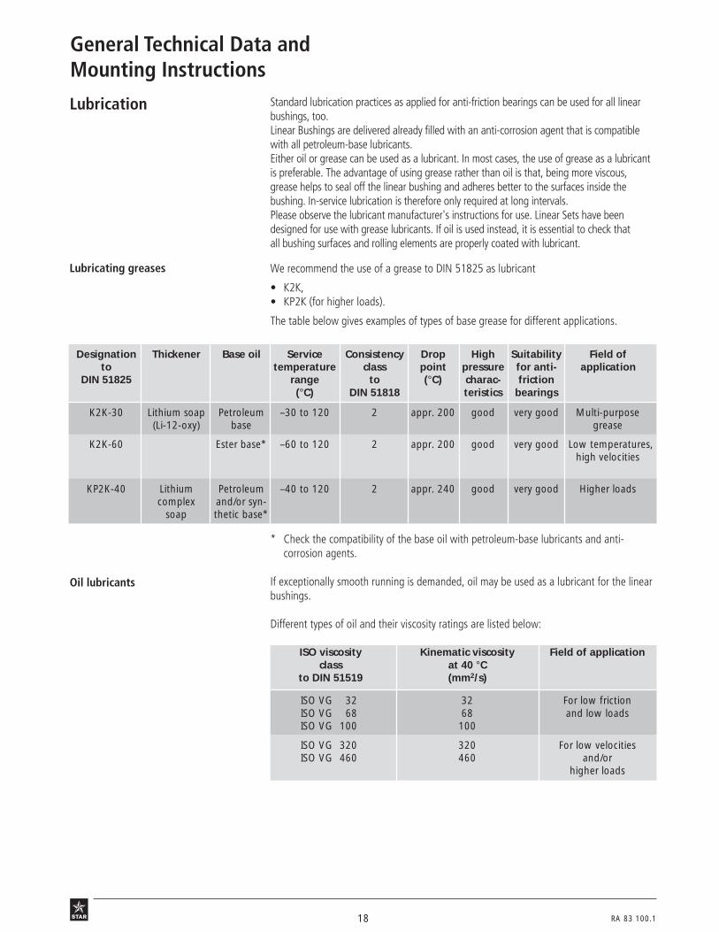
Lubrication
Oil lubricants
Standard lubrication practices as applied for anti-friction bearings can be used for all linearbushings, too.Linear Bushings are delivered already filled with an anti-corrosion agent that is compatiblewith all petroleum-base lubricants.Either oil or grease can be used as a lubricant. In most cases, the use of grease as a lubricantis preferable. The advantage of using grease rather than oil is that, being more viscous,grease helps to seal off the linear bushing and adheres better to the surfaces inside thebushing. In-service lubrication is therefore only required at long intervals.Please observe the lubricant manufacturer's instructions for use. Linear Sets have beendesigned for use with grease lubricants. If oil is used instead, it is essential to check thatall bushing surfaces and rolling elements are properly coated with lubricant.
We recommend the use of a grease to DIN 51825 as lubricant
• K2K,• KP2K (for higher loads).
The table below gives examples of types of base grease for different applications.
* Check the compatibility of the base oil with petroleum-base lubricants and anti-corrosion agents.
If exceptionally smooth running is demanded, oil may be used as a lubricant for the linearbushings.
Different types of oil and their viscosity ratings are listed below:
General Technical Data andMounting Instructions
Lubricating greases
RA 83 100.1 19
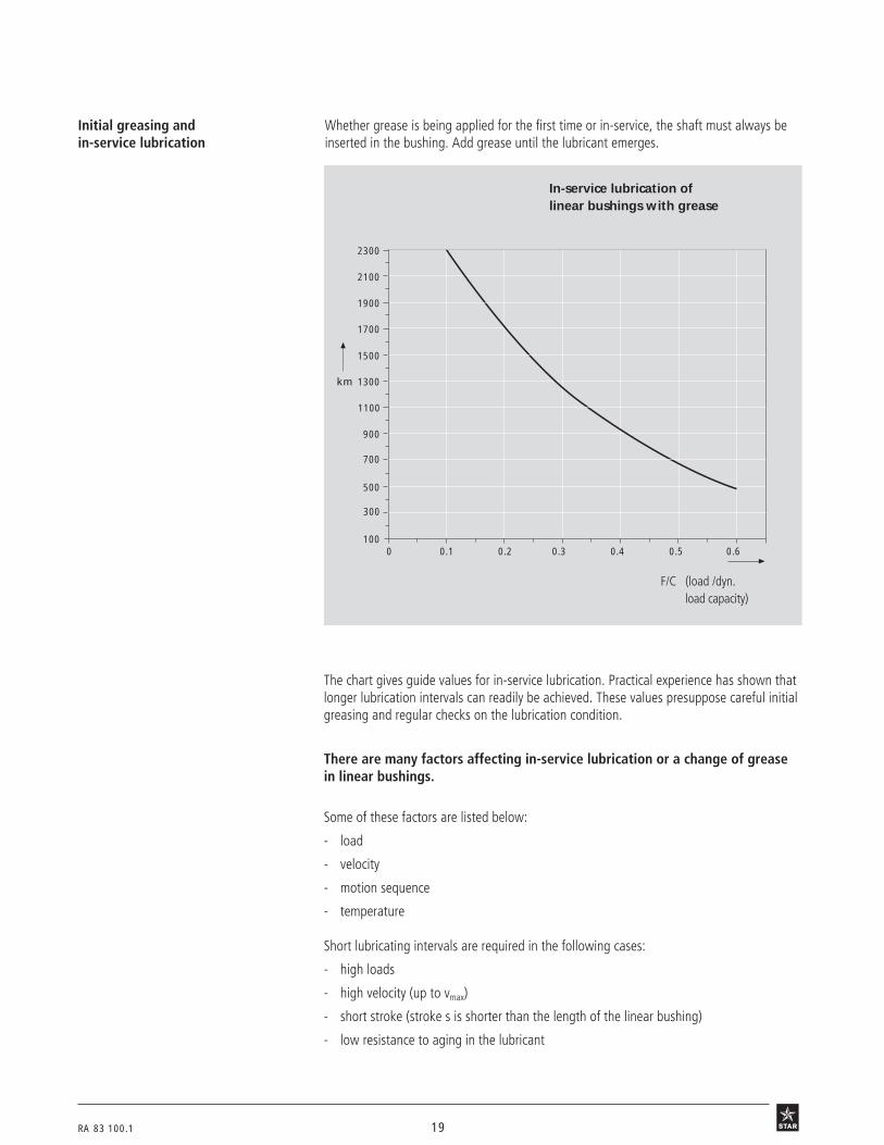
Whether grease is being applied for the first time or in-service, the shaft must always beinserted in the bushing. Add grease until the lubricant emerges.
The chart gives guide values for in-service lubrication. Practical experience has shown thatlonger lubrication intervals can readily be achieved. These values presuppose careful initialgreasing and regular checks on the lubrication condition.
F/C (load /dyn.load capacity)
In-service lubrication oflinear bushings with grease
3 N 85
Initial greasing andin-service lubrication
0 0.1 0.2 0.3
1300
900
500
100
km
0.4 0.5 0.6
2100
1700
300
700
1100
1500
1900
2300
There are many factors affecting in-service lubrication or a change of greasein linear bushings.
Some of these factors are listed below:
- load
- velocity
- motion sequence
- temperature
Short lubricating intervals are required in the following cases:
- high loads
- high velocity (up to vmax)
- short stroke (stroke s is shorter than the length of the linear bushing)
- low resistance to aging in the lubricant

20 RA 83 100.1
l
l
l
l
l
See Super Linear Bushings and – Lubrication and Retention
l
Axial retention of wiper sealand linear bushing required
Type ofLinear Bushing
Standard
– closed
– adjustable
– open
Super , – closed
– open
Super ,
Segmental
Compact
Radial
Notes:
Make sure there is sufficient retention in open-type versions.As far as possible, apply lubricant during longitudinal motion.Lube ports and lube grooves must be free of burrs.
Lubrication through gapbetween linear bushing andwiper seal
Lubrication throughlube port
Lubrication through lube portwith lubricating groove
3 N 103 3 N 104
General Technical Data andMounting Instructions
Lube port Lube port
Wiper seal Linear Bushing(without wiper seal)
Wiper seal Linear Bushing(without wiper seal)
Circumferential lubricating groove
Wiper seal Linear Bushing
In-service lubrication options in linear bushings
lLocate the lube port along thevisible ball recirculating track
lLocate the lube port along thevisible ball recirculating track
l
Locate the lube port near the slot(alignment during installation)
Lubrication causes pressure to build up. Always check thatthe linear bushing and the wiper seal fit tight.
Lube portsee Radial Linear Bushings
See Super Linear Bushings and – Technical Data – "customer-built housing"

RA 83 100.1 21
Corrosion-resistant steels are steels to DIN 17230 / EN 10088.In very critical, corrosive environments the parts must be checked under operatingconditions.Use appropriate anti-corrosive agents and lubricants.
In assemblies with rigid housings, etc., and long distances between shaft supports, shaftdeflection and the resultant pressure between the bushing edge and the shaft will shortenthe life of the assembly (this does not apply to Super Linear Bushings , and up to 30').For information on how to calculate shaft deflection see Technical Data on Precision SteelShafts.
Grease nipples
d 1 d 1
Shaft deflection
Corrosion-resistantmodels
Up to 100 °C; Standard Linear Bushings with wiper seals and separate wiper seals forRadial Linear Bushings: up to 80 °C (with brief peaks up to 100 °C).Higher temperatures are permissible only for sizes 12 to 80 Standard Linear Bushingswithout seals and at the cost of a reduction in load carrying capacity.(see temperature factor fT).
Operating temperatures
Linear Sets designed for in-service lubrication are provided with lube holes for greaselubrication. Adequate grease nipples are shown in the below table:
Ø d1 cone-type funnel-typegrease nipple grease nipple
DIN 71412 type A DIN 3405 type A(mm) part numbers part numbers
M6 8417-002-02 8417-001-05
M8 x 1 8417-003-02 8417-003-05
M10 x 1 8417-009-02 –

22 RA 83 100.1
Two linear bushings are required for linear motion assemblies using one shaft only.Assemblies with two shafts must have at least one of the shafts mounted in twolinear bushings.
Installation ofLinear Bushings
Shaft P (µm)
Ø d Zero clearance h7/H7
(mm) Standard, Segmental, Standard, Segmental,Super, Compact Super Compact1)
Radial Linear Bushings Linear Bushings Linear BushingsLinear Bushings
5 4 – 12 –
8 4 – 12 –
10 4 – 12 –
12 5 8 13 17
16 5 8 13 17
20 7 12 15 20
25 9 15 17 23
30 9 15 17 23
40 11 18 19 25
50 13 22 21 28
60 16 – 24 –
80 22 – 30 –
General Technical Data andMounting Instructions
Retention See "Technical Data" of the various linear bushing types.
1) For the "Compact RT" type, the values in the "Zero clearance" columne apply.
To prevent distortion, which would increase running friction and shorten the service lifeof the assembly, special care must be taken to ensure precise spacing and parallelismbetween the two shafts with their associated linear bushings.
Recommended values for maximum spacing inaccuracy P, including deviation fromparallelism, for assemblies incorporating linear bushings are as follows:
RA 83 100.1 23
5 o 2
Arbor
d -0.05-0.15
D-0.1-0.4
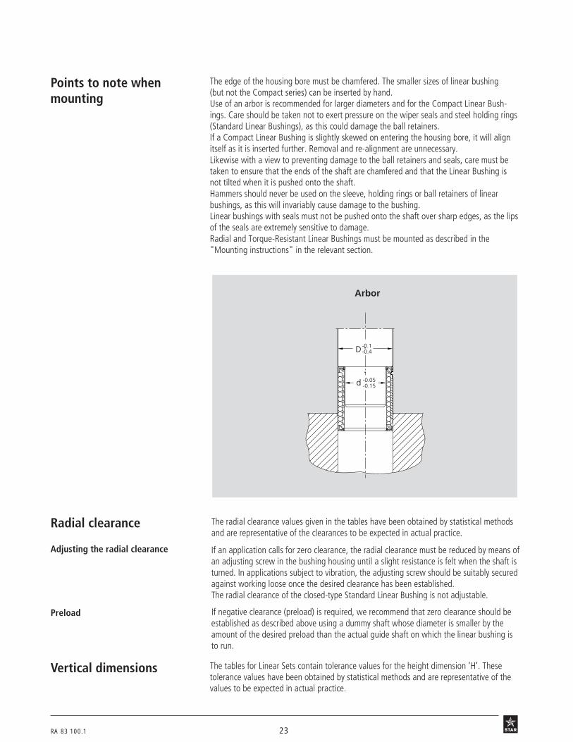
Points to note whenmounting
Radial clearance
The edge of the housing bore must be chamfered. The smaller sizes of linear bushing(but not the Compact series) can be inserted by hand.Use of an arbor is recommended for larger diameters and for the Compact Linear Bush-ings. Care should be taken not to exert pressure on the wiper seals and steel holding rings(Standard Linear Bushings), as this could damage the ball retainers.If a Compact Linear Bushing is slightly skewed on entering the housing bore, it will alignitself as it is inserted further. Removal and re-alignment are unnecessary.Likewise with a view to preventing damage to the ball retainers and seals, care must betaken to ensure that the ends of the shaft are chamfered and that the Linear Bushing isnot tilted when it is pushed onto the shaft.Hammers should never be used on the sleeve, holding rings or ball retainers of linearbushings, as this will invariably cause damage to the bushing.Linear bushings with seals must not be pushed onto the shaft over sharp edges, as the lipsof the seals are extremely sensitive to damage.Radial and Torque-Resistant Linear Bushings must be mounted as described in the"Mounting instructions" in the relevant section.
The radial clearance values given in the tables have been obtained by statistical methodsand are representative of the clearances to be expected in actual practice.
If an application calls for zero clearance, the radial clearance must be reduced by means ofan adjusting screw in the bushing housing until a slight resistance is felt when the shaft isturned. In applications subject to vibration, the adjusting screw should be suitably securedagainst working loose once the desired clearance has been established.The radial clearance of the closed-type Standard Linear Bushing is not adjustable.
If negative clearance (preload) is required, we recommend that zero clearance should beestablished as described above using a dummy shaft whose diameter is smaller by theamount of the desired preload than the actual guide shaft on which the linear bushing isto run.
Adjusting the radial clearance
Preload
Vertical dimensions The tables for Linear Sets contain tolerance values for the height dimension ‘H’. Thesetolerance values have been obtained by statistical methods and are representative of thevalues to be expected in actual practice.

24 RA 83 100.1
General Technical Data andMounting Instructions
Einheitsbohrung
Tolerances forinside dimensions
Tolerances in µm = 0.001 mm
Millimeters µm Inches
1 millimeter 1 1000 0,0393701
1 µm 0.001 1 3.93701 · 10–5
1 inch 25.4 25400 1
Conversion from millimeters to inches
Example of conversion from µm to inches:
Which are the tolerances (in inches) for a bore of 3.5 inch diameter?Bore diameter 3.5 inch = 3.5 · 25.4 mm = 88.9 mmFor a bore diameter of 88.9 mm and a tolerance range of H7, the upper tolerance limit is+35 µm and the lower tolerance limit 0 µmMax. offsize = +35 µm = +35 · 3.93701 · 10–5 inch = 1.3779 · 10–3 inchMin. offsize = 0 µm
Rated Tolerances for inside dimensionsdimensions(mm) G7 H5 H6 H7 H8 H11 H12 H13 JS6 JS7 JS14 K6 K7 M6 P9
between 3 +16 +5 +8 +12 +18 +75 +120 +180 +4 +6 +150 +2 +3 –1 –12and 6 +4 0 0 0 0 0 0 0 –4 –6 –150 –6 –9 –9 –42
between 6 +20 +6 +9 +15 +22 +90 +150 +220 +4.5 +7.5 +180 +2 +5 –3 –15and 10 +5 0 0 0 0 0 0 0 –4.5 –7.5 –180 –7 –10 –12 –51
between 10 +24 +8 +11 +18 +27 +110 +180 +270 +5.5 +9 +215 +2 +6 –4 –18and 18 +6 0 0 0 0 0 0 0 –5.5 –9 –215 –9 –12 –15 –61
between 18 +28 +9 +13 +21 +33 +130 +210 +330 +6.5 +10.5 +260 +2 +6 –4 –22and 30 +7 0 0 0 0 0 0 0 –6.5 –10.5 –260 –11 –15 –17 –74
between 30 +34 +11 +16 +25 +39 +160 +250 +390 +8 +12.5 +310 +3 +7 –4 –26and 50 +9 0 0 0 0 0 0 0 –8 –12.5 –310 –13 –18 –20 –88
between 50 +40 +13 +19 +30 +46 +190 +300 +460 +9.5 +15 +370 +4 +9 –5 –32and 80 +10 0 0 0 0 0 0 0 –9.5 –15 –370 –15 –21 –24 –106
between 80 +47 +15 +22 +35 +54 +220 +350 +540 +11 +17.5 +435 +4 +10 –6 –37and 120 +12 0 0 0 0 0 0 0 –11 –17.5 –435 –18 –25 –28 –124
between 120 +54 +18 +25 +40 +63 +250 +400 +630 +12.5 +20 +500 +4 +12 –8 –43and 180 +14 0 0 0 0 0 0 0 –12.5 –20 –500 –21 –28 –33 –143
between 180 +61 +20 +29 +46 +72 +290 +460 +720 +14.5 +23 +575 +5 +13 –8 –50and 250 +15 0 0 0 0 0 0 0 –14.5 –23 –575 –24 –33 –37 –165

RA 83 100.1 25
Einheitswelle
Tolerances foroutside dimensions
Tolerances in µm = 0.001 mm
Rated Tolerances for outside dimensionsdimensions(mm) g7 h5 h6 h7 h8 h11 h12 h13 js6 js7 js14 k6 k7 m6 p9
between 3 –4 0 0 0 0 0 0 0 +4 +6 +150 +9 +13 +12 +42and 6 –16 –5 –8 –12 –18 –75 –120 –180 –4 –6 –150 +1 +1 +4 +12
between 6 –5 0 0 0 0 0 0 0 +4.5 +7.5 +180 +10 +16 +15 +51and 10 –20 –6 –9 –15 –22 –90 –150 –220 –4.5 –7.5 –180 +1 +1 +6 +15
between 10 –6 0 0 0 0 0 0 0 +5.5 +9 +215 +12 +19 +18 +61and 18 –24 –8 –11 –18 –27 –110 –180 –270 –5.5 –9 –215 +1 +1 +7 +18
between 18 –7 0 0 0 0 0 0 0 +6.5 +10.5 +260 +15 +23 +21 –and 30 –28 –9 –13 –21 –33 –130 –210 –330 –6.5 –10.5 –260 +2 +2 +8
between 30 –9 0 0 0 0 0 0 0 +8 +12.5 +310 +18 +27 +25 –and 50 –34 –11 –16 –25 –39 –160 –250 –390 –8 –12.5 –310 +2 +2 +9
between 50 –10 0 0 0 0 0 0 0 +9.5 +15 +370 +21 +32 +30 –and 80 –40 –13 –19 –30 –46 –190 –300 –460 –9.5 –15 –370 +2 +2 +11
between 80 –12 0 0 0 0 0 0 0 +11 +17.5 +435 +25 +38 +35 –and 120 –47 –15 –22 –35 –54 –220 –350 –540 –11 –17.5 –435 +3 +3 +13
between 120 –14 0 0 0 0 0 0 0 +12.5 +20 +500 +28 +43 +40 –and 180 –54 –18 –25 –40 –63 –250 –400 –630 –12.5 –20 –500 +3 +3 +15
between 180 –15 0 0 0 0 0 0 0 +14.5 +23 +575 +33 +50 +46 –and 250 –61 –20 –29 –46 –72 –290 –460 –720 –14.5 –23 –575 +4 +4 +17
Note:
This catalog refers to the new ISO standards throughout. In some cases, however, the old standards are still used in actual practice. Thecorrespondence between standards is given below.
New designation Old designation
Hexagon socket ISO 4762 DIN 912head cap screws
Hexagon head screws ISO 4017 DIN 933

26 RA 83 100.1
The Standard Linear Bushing consists of:• a hardened and ground outer sleeve
• a steel ball retainer (plastic ball retainer in sizes 5 and 8)
• balls made of anti-friction bearing steel
• steel snap rings or wiper-type seal rings
Types• Closed
• Adjustable (slotted)
• Open
• With or without seals
• Various types of screw-mounting Linear Sets (Standard Linear Bushing with PrecisionHousing)
• Adjustable and open-type Standard Linear Bushings are also available withSTAR Resist corrosion protection (yellow chromatized zinc-iron coating) anda special version (black chromatized)
Advantages• Long service life
• Low friction
• High running speed
• Sturdy solid-metal construction suited to industrial workshop environments
• Withstands temperatures above 100 °C
• Insensitive to dirt, an especially important feature in woodworking machines
STAR – Standard Linear Bushings
The Linear Bushing for extra-sturdy linearmotion assemblies
Standard Linear Bushings have a service history that goes back over several de-cades and covers successful employment in all fields of mechanical engineering, inthe construction of special machinery, jigs and equipment. Made entirely of solidmetal, Standard Linear Bushings are especially suited for applications requiring arugged construction and a high degree of insensitivity to dirt.Long service life, precision and high efficiency are the classical features charac-terizing these guide elements.

RA 83 100.1 27
Open type
3 N1
12 01
Adjustable (slotted) type

28 RA 83 100.1
STAR – Standard Linear BushingsTechnical DataPlease observe the general technical principles and mounting instructions at the beginning of this catalog aswell as the additional technical data given below.
Outer dimensions/interchangeability Standard Linear Bushings have the same outer dimensions and are therefore interchange-able with Super Linear Bushings (caution: different retention, radial clearance, loadcapacities and lubrication).
Standard Linear Bushings are available with seals. Open-type Standard Linear Bushings insizes 20 to 80 can also be supplied fully sealed (with seal strip), though this will result ingreater friction.
Low friction Very low friction due to the rolling friction principle. Even if the lubricant supply were torun short, there would be no appreciable increase in friction. Extremely low breakawayforces.The friction µ of unsealed Standard Linear Bushings using oil as a lubricant lies between0.001 and 0.004.The friction is lowest under high load. It may, however, be greater than the stated valuewhen only a slight load is applied.
The frictional drag in linear bushings sealed at both ends and not subject to radial loadingdepends on the speed and the type of lubrication and is shown in the below table.
Sealing
Shaft Closed and adjustable Open typetype
Ø d Breakaway force Frictional drag Breakaway force Frictional drag(mm) (N) approx. (N) approx. (N) approx. (N) approx.
5 0.8 0.4 – –
8 1 0.5 – –
12 6 2 8 3
16 9 3 12 4
20 12 4 16 6
25 14 5 19 7
30 18 6 24 8
40 24 8 32 11
50 30 10 40 14
60 36 12 48 16
80 45 15 60 20
Velocity and accelerationType vmax (m/s) amax (m/s2)
Standard Linear Bushing d ≤ 40 mm 2.5 100
Standard Linear Bushing d ≥ 50 mm 2 50

RA 83 100.1 29
3 N 111
Operating temperatures Linear bushings without seals: up to 100 °C. Higher temperatures are permissible forsizes 12 to 80 though at the cost of reduced load capacity (see temperature factor ft in"General Technical Data and Mounting Instructions").
Linear bushings with seals: up to 80 °C (brief peaks up to 100 °C).
Direction of load and its influence onthe load-carrying capacity of closedand adjustable Standard LinearBushings
The load capacities given are valid for installation in "min" position and should be takenas the basis for calculation.In applications where the direction of load is exactly known and where the StandardLinear Bushings can be mounted in the "max" position, the load capacity rating must bemultiplied by the factors fmax (dynamic load capacity C) or f0 max (static load capacity C0)from the table.
Shaft Load capacity
Ø d factors
(mm) fmax f0 max
5, 8, 12, 16 1.15 1.42
20, 25 1.19 1.46
30, 40, 50, 60, 80 1.06 1.28
max.min.
10 B 2
Direction of load and its influence onthe load-carrying capacity of openStandard Linear Bushings
The load capacities C and C0 apply when the load is acting along the line = 0°.If the load is acting in any other direction, these load capacities must be multiplied by thefactors f (dynamic load capacity C) or f 0 (static load capacity C0).A reduction in the load capacity can be avoided by selective circumferential positioning ofthe Standard Linear Bushing (see Linear Sets with side opening).
Load capacity factors
1.2
1.0
0.8
0.6
1.4
0.4
(°)
f οf
0°
30° 330°
270°
240°
210°
180°
150°
120°
90°
60° 300°
f
f ο
f
f ο
f
f ο
(°)
0°
30° 330°
270°
240°
210°
180°
150°
120°
90°
60° 300°
1.2
1.0
0.8
0.6
1.4
0.4
Shaft diameter d 20 and 25 Shaft diameter d 30 to 80
3 N 110

30 RA 83 100.1
STAR – Standard Linear BushingsCustomer-built Housings
RetentionStandard Linear Bushings
closed type
adjustable
• Retaining rings
• Metal case
• Special arrangement
6 o 3601
Retention by means ofmetal case 2)
Axial retention by means ofscrews and cover plates
Retention by means ofretaining rings to DIN 471
Retention by means ofretaining rings to DIN 472
Shaft Retaining rings DIN 471 Retaining rings DIN 472
Ø d Part numbers Dimensions Part numbers Dimensions(mm)
5 8410-712-00 12 x 1 8410-207-00 12 x 1
8 8410-713-00 16 x 1 8410-208-00 16 x 1
12 8410-714-00 22 x 1.2 8410-209-00 22 x 1
16 8410-715-00 27 x 1.21) 8410-210-00 26 x 1.2
20 8410-716-00 33 x 1.51) 8410-211-00 32 x 1.2
25 8410-717-00 42 x 1.75 8410-212-00 40 x 1.75
30 8410-718-00 48 x 1.75 8410-213-00 47 x 1.75
40 8410-719-00 62 x 2 8410-214-00 62 x 2
50 8410-720-00 75 x 2.5 8410-215-00 75 x 2.5
60 8410-721-00 90 x 3 8410-216-00 90 x 3
80 8410-722-00 120 x 4 8410-217-00 120 x 4
6 o 2 6 o 4
1) not to DIN 471
2) For part numbers and dimensions refer to Super Linear Bushings and ,customer-built housings

RA 83 100.1 31
Standard Linear Bushings
open type
• Dimensions of retention hole
The open-type linear bushing has beenprovided with a retention hole, thusallowing axial and radial securing.
3N72
3N73
3N74
3N76
3N78
3N75
3N77
3N79
0.7
20
ø3.
1
1.7
30
ø3.
1
2
2
50
ø5.
1
2.5
4.5
80
ø5.
1
2.5
1
ø3.
1
1.5
25
2.3
40
ø3.
1
1.5
3.5
60
ø5.
1
2.5
= =

32 RA 83 100.1
STAR – Standard Linear BushingsCustomer-built Housings• Retention by means of locating screw
Points to note when mounting:Open-type Standard Linear Bushings havebeen provided with the necessary retentionhole. On installation, the retention hole inthe Linear Bushing must be aligned withthe tapped hole in the housing. The screwis then inserted, screwed down to thespecified depth and tightened to thespecified torque.
3 N 200 3 N 201
3 N 202
d = 20 d = 25
d = 30, 40, 50, 60, 80
L
d
K2
L
d
K 2
L
d
3N79
3 N 203
3 N 205
= =
Shaft Dimensions (mm) Locating screw
Ø d L K2 L1 L2 L3 L4 D1 D2 D3 D4 TighteningPart number torque
(mm) min. +0.2 min. +0.1 H13 H13 (Nm)
20 25.5–0.1 0 8.5+0.2 6.5 1.3 2.5 3.1 M4 4.5 8 8429-009-01 1.9
25 33.05–0.1 1.5 10+0.2 8 2 3.2 3.1 M4 4.5 8 8427-009-09 1.9
30 36–0.15 2 10+0.2 8 2 3.2 3.1 M4 4.5 8 8427-009-09 1.9
40 42.9–0.15 1.5 10+0.2 8 2 3.2 3.1 M4 4.5 8 8427-009-09 1.9
50 58.5–0.2 2.5 17.5+0.5 13.5 3.7 6 5.1 M8 9 15 8427-005-09 16
60 71.5–0.25 2.5 17.5+0.5 13.5 3.7 6 5.1 M8 9 15 8427-006-09 16
80 85.5–0.25 2.5 17.5+0.5 13.5 3.7 6 5.1 M8 9 15 8427-006-09 16
L4
D4 D3 D2
L3
L2
D1
L1
L
ø 0.05

RA 83 100.1 33
Locating screwsfor shaft Ø 20
dk
d1
d
kl1
ls s
dk
d1
d
kl1
l
for shaft Ø 25, 30, 40, 50, 60, 80
The locating screws are of the self-locking type.
Shaft Part Dimensions (mm) Tighteningnumbers torque
Ø d(mm) d dk d1 l l1 k s (Nm)
20 8429-009-01 M4 7.6 3 10.15 5.7 2.2 2.5 1.9
25, 30, 40 8427-009-09 M4 7 3 14.1 6.5 2.8 2.5 1.9
50 8427-005-09 M8 13 5 22.8 12.5 5 5 16
60, 80 8427-006-09 M8 13 5 29.7 12.5 5 5 16
Rotary retention
Axial retention• Axial retention by means of screws andcover plates, rotary retention by meansof pin or plates.

34 RA 83 100.1
STAR – Standard Linear Bushings
3 N 9
Ordering data
Shaft Part numbers Mass
Ø d without with two (kg)(mm) seals seals
5 0600-305-00 0602-305-10 0.01
8 0600-308-00 0602-308-10 0.02
12 0600-012-00 0602-012-10 0.04
16 0600-016-00 0602-016-10 0.05
20 0600-020-00 0602-020-10 0.10
25 0600-025-00 0602-025-10 0.19
30 0600-030-00 0602-030-10 0.32
40 0600-040-00 0602-040-10 0.62
50 0600-050-00 0602-050-10 1.14
60 0600-060-00 0602-060-10 2.11
80 0600-080-00 0602-080-10 4.70
Structural design
• Hardened and ground outer sleeve
• Steel ball retainer (plastic ball retainer insizes 5 and 8)
• Balls made of anti-friction bearing steel
• Steel holding rings or seals
• Closed version, for use on unsupportedshafts
closed type
With one seal 0601-…-10
Standard Linear Bushings, 0600-closed type, without seals
Standard Linear Bushings, 0602-closed type, with seals
The figures for dynamic load-carrying capacity have been calculated assuming a nominal travel of 100,000 m.For a nominal travel of 50,000 m, the 'C' figures in the table must be multiplied by a factor of 1.26.

RA 83 100.1 35
Dimensions
Dd
C
C1
C2
D1
1) Sizes 5 and 8 have a plastic ball retainer.2) Statistically determined from the working bore diameter and shaft tolerance. Recommended housing bore tolerance: H6 or H7.3) The load capacities stated are minimum values as the position and direction of load cannot always be precisely defined.
Dimensions (mm) No. of ball Working bore Radial Load capacities3)
circuits diameter tolerance clearance2) dyn. stat.C C0
Ø d D C C1 C2 D1 (µm) (µm) (N) (N)h5 h12 H13 h6 h7
51)
12 22 14.2 1.1 11.1 4+11 +16 +20
180 140+1 +4 +4
81)
16 25 16.2 1.1 14.7 4+12 +18 +24
320 240+2 +5 +5
12 22 32 22.6 1.3 20.5 4+12 +20 +26
420 280+2 +5 +6
16 26 36 24.6 1.3 24.9 4+14 +22 +28
580 440+2 +5 +6
20 32 45 31.2 1.6 30.5 5+14 +23 +31
1170 860+2 +6 +6
25 40 58 43.7 1.85 38.5 5+16 +25 +32
2080 1560+2 +6 +7
30 47 68 51.7 1.85 44.5 6+16 +25 +32
2820 2230+2 +6 +7
40 62 80 60.3 2.15 58 6+19 +30 +38
5170 3810+2 +7 +8
50 75 100 77.3 2.65 71 6+19 +30 +38
8260 6470+2 +7 +8
60 90 125 101.3 3.15 85 6+19 +33 +43
11500 9160+2 +7 +8
80 120 165 133.3 4.15 114 6+24 +37 +47
21000 16300+2 +8 +9
11 o 311 o 2

36 RA 83 100.1
STAR – Standard Linear Bushings
Structural design
• Hardened and ground outer sleeve
• Steel ball retainer (plastic ball retainer insizes 5 and 8)
• Balls made of anti-friction bearing steel
• Steel holding rings or seals
• Adjustable radial clearance
11 o 1
Shaft Part numbers Mass
Ø d without with two (kg)(mm) seals seals
5 0610-305-00 0612-305-10 0.01
8 0610-308-00 0612-308-10 0.02
12 0610-012-00 0612-012-10 0.04
16 0610-016-00 0612-016-10 0.05
20 0610-020-00 0612-020-10 0.10
25 0610-025-00 0612-025-10 0.19
30 0610-030-00 0612-030-10 0.32
40 0610-040-00 0612-040-10 0.62
50 0610-050-00 0612-050-10 1.14
60 0610-060-00 0612-060-10 2.11
80 0610-080-00 0612-080-10 4.70
Ordering data
Standard Linear Bushings, 0610-adjustable, without seals
Standard Linear Bushings, 0612-adjustable, with seals
adjustable type
With one seal: 0611-…-10.
The figures for dynamic load-carrying capacity have been calculated assuming a nominal travel of 100,000 m.For a nominal travel of 50,000 m, the ‘C’ figures in the table must be multiplied by a factor of 1.26.

RA 83 100.1 37
Dimensions
Dd
C
C1
C2
D1 E
11 o 2 11 o 4
Dimensions (mm) No. of Load capacities3) Adjustableball circuits dyn. stat. radial clearance
C C0 (shaft/bore)(N) (N) (µm)
Ø d D2) C C1 C2 D1 Eh5 h12 H13 h6/H6 h6/JS6 h6/K6 h7/H7 h7/JS7 h7/K7
51)
12 22 14.2 1.1 11.1 1.5 4 180 140+28 +23 +19 +37 +28 +25
+10 +4 +1 +12 +3 0
81)
16 25 16.2 1.1 14.7 1.5 4 320 240+31 +25 +22 +41 +32 +29
+11 +6 +2 +14 +5 +2
12 22 32 22.6 1.3 20.5 1.5 4 420 280+34 +28 +23 +46 +36 +31
+13 +6 +2 +16 +5 +1
16 26 36 24.6 1.3 24.9 1.5 4 580 440+36 +29 +25 +48 +37 +33
+13 +7 +2 +16 +6 +1
20 32 45 31.2 1.6 30.5 2.0 5 1170 860+41 +33 +28 +55 +42 +37
+15 +7 +2 +18 +6 0
25 40 58 43.7 1.85 38.5 2.0 5 2080 1560+43 +35 +30 +56 +44 +38
+15 +7 +2 +19 +6 +1
30 47 68 51.7 1.85 44.5 2.0 6 2820 2230+43 +35 +30 +56 +44 +38
+15 +7 +2 +19 +6 +1
40 62 80 60.3 2.15 58 2.0 6 5170 3810+51 +41 +36 +67 +52 +46
+18 +9 +3 +22 +7 +1
50 75 100 77.3 2.65 71 2.0 6 8260 6470+51 +41 +36 +67 +52 +46
+18 +9 +3 +22 +7 +1
60 90 125101.3 3.15 85 2.0 6 11500 9160+57 +46 +39 +76 +59 +51
+20 +9 +2 +25 +7 0
80 120 165133.3 4.15 114 2.0 6 21000 16300+61 +50 +43 +80 +62 +55
+21 +10 +3 +26 +9 +1
1) Sizes 5 and 8 have a plastic ball retainer.2) The tolerance stated is valid for the Linear Bushing in the unslotted condition.3) The load capacities stated are minimum values as the position and direction of load cannot always be precisely defined.

38 RA 83 100.1
STAR – Standard Linear Bushings
StandardLinear Bushings, 0630-open type, without seals
StandardLinear Bushings, 0632-open type, with seals
Shaft Part numbers Mass
Ø d without with two fully (kg)(mm) seals seals sealed
121) 0630-012-00 0632-012-00 – 0.03
161) 0630-016-00 0632-016-00 – 0.04
20 0630-020-00 0632-020-00 0632-020-05 0.08
25 0630-025-00 0632-025-00 0632-025-05 0.15
30 0630-030-00 0632-030-00 0632-030-05 0.26
40 0630-040-00 0632-040-00 0632-040-05 0.52
50 0630-050-00 0632-050-00 0632-050-05 0.95
60 0630-060-00 0632-060-00 0632-060-05 1.76
80 0630-080-00 0632-080-00 0632-080-05 3.92
Ordering data
open type
1) without bore for axial and radial retention
With one seal 0631-…-00
Load capacity factors
(°)f οf
0°30° 330°
270°
240°
210°180°
150°
120°
90°
60° 300°
f1.2
1.0
0.8
0.6
f ο
1.4
0.6
Shaft Ø d 20 and 25 Shaft Ø d 30 to 80
3 N 70 3 N 71
Structural design
• Hardened and ground outer sleeve
• Steel ball retainer
• Balls made of anti-friction bearing steel
• Steel holding rings or seals
• With bore for axial and radial retention(except sizes 12 and 16)
0°30° 330°
270°
240°
210°180°
150°
120°
90°
60° 300°
1.2
1.0
0.8
0.6
f οf(°)
0.4
1.4f ο
f
The figures for dynamic load-carrying capacity have been calculated assuming a nominal travel of 100,000 m.For a nominal travel of 50,000 m, the ‘C’ figures in the table must be multiplied by a factor of 1.26.
12 o 1 a r
3N70

RA 83 100.1 39
Dimensions
Dd
C
C1
E
=0°C2
D1
1) The tolerance stated is valid for the Linear Bushing in the unslotted condition.2) Lower limit relative to nominal shaft dimension d.3) The load capacities C and C0 apply only when the load is acting along the line = 0°.
If the load is acting in any other direction, these load capacities must be multiplied by the factor f or f 0.For loads acting on the opening in sizes 12 and 16: = 180°
f = 0.37
Dimensions (mm) Angle No. of Load capacities3) Adjustable(°) ball dyn. stat. radial clearance
circuits C C0 (shaft/bore)(N) (N) (µm)
Ø d D1) C C1 C2 D1 E2) ah5 h12 H13 h6/H6 h6/JS6 h6/K6 h7/H7 h7/JS7 h7/K7
12 22 32 22.6 1.3 20.5 7.5 78 3 430 290+34 +28 +23 +46 +36 +31
+13 +6 +2 +16 +5 +1
16 26 36 24.6 1.3 24.9 10.0 78 3 600 450+36 +29 +25 +48 +37 +33
+13 +7 +2 +16 +6 +1
20 32 45 31.2 1.6 30.5 10.0 60 4 1280 970+41 +33 +28 +55 +42 +37
+15 +7 +2 +18 +6 0
25 40 58 43.7 1.85 38.5 12.5 60 4 2270 1750+43 +35 +30 +56 +44 +38
+15 +7 +2 +19 +6 +1
30 47 68 51.7 1.85 44.5 12.5 50 5 2890 2390+43 +35 +30 +56 +44 +38
+15 +7 +2 +19 +6 +1
40 62 80 60.3 2.15 58 16.8 50 5 5280 4000+51 +41 +36 +67 +52 +46
+18 +9 +3 +22 +7 +1
50 75 100 77.3 2.65 71 21.0 50 5 8470 6900+51 +41 +36 +67 +52 +46
+18 +9 +3 +22 +7 +1
60 90 125 101.3 3.15 85 27.2 54 5 11800 9780+57 +46 +39 +76 +59 +51
+20 +9 +2 +25 +7 0
80 120 165 133.3 4.15 114 36.3 54 5 21500 17400+61 +50 +43 +80 +62 +55
+21 +10 +3 +26 +9 +1
Sizes 12 and 16 must be mounted asshown here (mirror-symmetrically) toprevent their lifting from the shaft. It isnot possible to adjust a single linearbushing (with slotted housing adjustableby means of an adjusting screw) to zeroclearance.
12 o 3
12 o 2

40 RA 83 100.1
1065-... 1066-...
1067-... 1068-...
1073-... 1074-...
1081-...
STAR – Linear Sets with Standard Linear BushingsOverview
Open type
For long guideways when the shafts mustbe supported and high rigidity is required.
Open type, adjustableFor use when zero clearance or preload isrequired.
With side openingThe load carrying capacity of open linearbushings is reduced when the load isapplied to the "open" portion of thebushing. The Linear Set with Side Openinghas been developed to overcome thisdisadvantage and to permit selectivecircumferential positioning of the openlinear bushing.
With side opening, adjustableFor use when zero clearance or preload isrequired.
Flanged type
This element was developed as a comple-ment to our Linear Set series for use inapplications requiring the shaft to bearranged at right angles to the mountingbase.
Linear SetsClosed type
Standard type with fixed working borediameter.
Adjustable type
For use when zero clearance or preload isrequired.

RA 83 100.1 41
• Thanks to their special material and sturdy wall thickness, Precision Housingsoffer very high rigidity regardless of the direction of loading, even when the loadcarrying capacity of the assembly is exploited to the full.
• The housings are easy to align during mounting, so that no adverse stress is exertedon the linear bushing.
• Their high precision guarantees trouble-free running of our linear bushings and fullinterchangeability of all units.
• Since our housings are produced in large numbers, they offer the same high qualityas the user’s own design at a price that no in-house design can match for economy.
Advantages/Technical Data/Notes for Mounting
Advantages
Technical dataOperating temperatures 80 °C, with brief peaks up to 100 °C
The radial clearance values given in the tables have been obtained by statistical methodsand are representative of the values to be expected in actual practice.STAR Linear Sets 1066-...-, 1068-...- and 1074-...00 are adjusted to zero clearance on ashaft of diameter accurate to a tolerance of h5 (lower limit) before leaving the factory.
Notes for mountingRadial clearance
The tables for Linear Sets contain tolerance values for the height dimension 'H'.These tolerance values have been obtained by statistical methods and are representativeof the values to be expected in actual practice.
Vertical dimensions
Screws We recommend screws to ISO 4762-8.8 for mounting Linear Sets.
42 RA 83 100.1
STAR – Linear Sets with Standard Linear Bushings
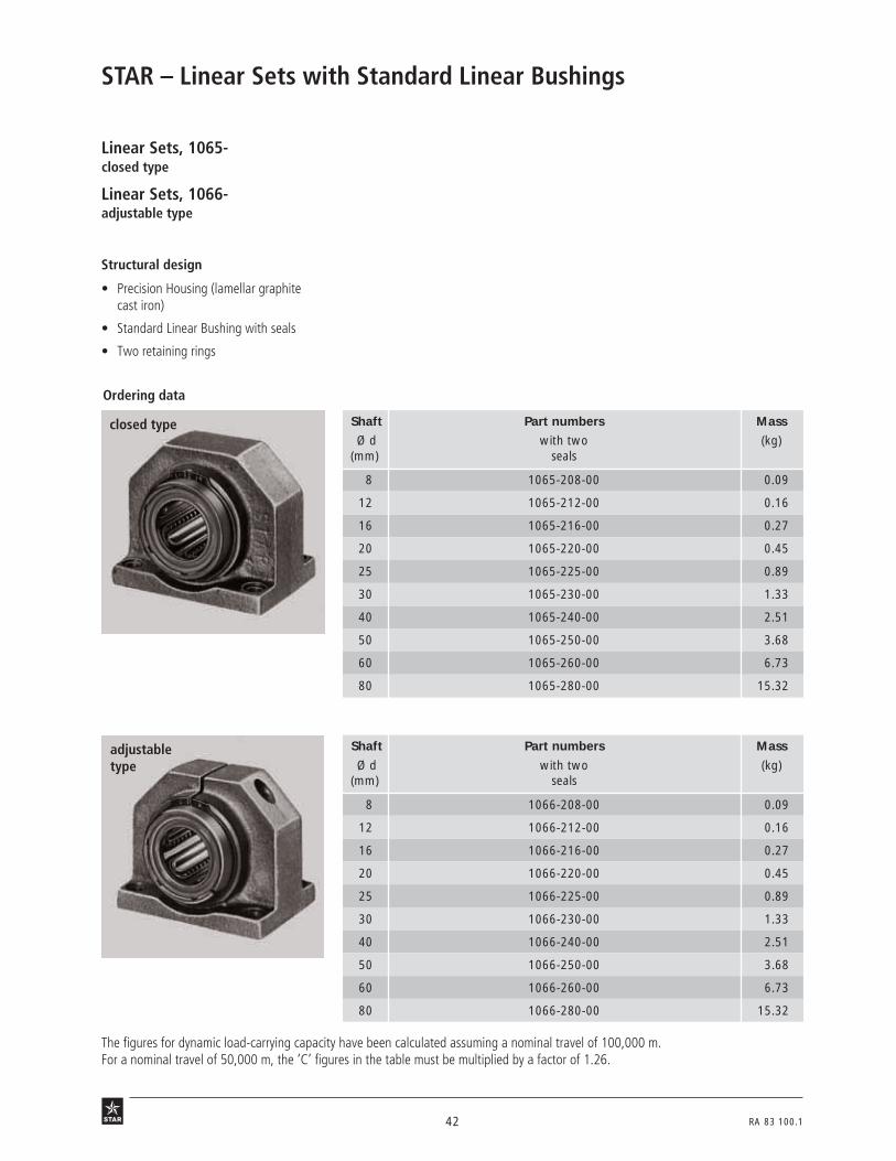
Structural design
• Precision Housing (lamellar graphitecast iron)
• Standard Linear Bushing with seals
• Two retaining rings
Linear Sets, 1065-closed type
Linear Sets, 1066-adjustable type
36 o 1r
Ordering data
closed type Shaft Part numbers Mass
Ø d with two (kg)(mm) seals
8 1065-208-00 0.09
12 1065-212-00 0.16
16 1065-216-00 0.27
20 1065-220-00 0.45
25 1065-225-00 0.89
30 1065-230-00 1.33
40 1065-240-00 2.51
50 1065-250-00 3.68
60 1065-260-00 6.73
80 1065-280-00 15.32
36 o 2r
adjustabletype
Shaft Part numbers Mass
Ø d with two (kg)(mm) seals
8 1066-208-00 0.09
12 1066-212-00 0.16
16 1066-216-00 0.27
20 1066-220-00 0.45
25 1066-225-00 0.89
30 1066-230-00 1.33
40 1066-240-00 2.51
50 1066-250-00 3.68
60 1066-260-00 6.73
80 1066-280-00 15.32
The figures for dynamic load-carrying capacity have been calculated assuming a nominal travel of 100,000 m.For a nominal travel of 50,000 m, the ‘C’ figures in the table must be multiplied by a factor of 1.26.

RA 83 100.1 43
Dimensions
open type
36 o 3
adjustable type
E 2
B
S
V
H
E 1
A
A1
45°
B1
L
d D H1
E 2
B
S
V
H
E 1
A
A1
45°
B1
L
d D H1
SW
36 o 4Dimensions (mm) Radial clearance2) Tolerance Load capa-(µm) (µm) cities4) (N)
Ø d D H H11) L A1) A1
1) B1) B1 E1 E2 S V1) SW 1065-... 1066-... for dimension H3) dyn. stat.
with shaft C C0
h6 h7
8 16 15 28 25 32 16 28 14 25±0.15 20±0.15 3.4 5 2+18 +24 +6
320 240+5 +5 –17
12 22 18 35 32 42 21 32 20 32±0.15 23±0.15 4.5 5.5 2.5+20 +26 +6
420 280+5 +6 –17
16 26 22 42 36 50 26 35 22 40±0.15 26±0.15 4.5 6.5 3+22 +28 +5
580 440+5 +6 –18
20 32 25 50 45 60 28 42 28 45±0.15 32±0.15 4.5 8 3+23 +31 +5
1170 860+6 +6 –19
25 40 30 60 58 74 38 54 40 60±0.15 40±0.15 5.5 9 5+25 +32 +5
2080 1560+6 +7 –19
30 47 35 70 68 84 41 60 48 68±0.20 45±0.20 6.6 10 5+25 +32 +5
2820 2230+6 +7 –19
40 62 45 90 80 108 51 78 56 86±0.20 58±0.20 9 12 6+30 +38 +4
5170 3810+7 +8 –21
50 75 50 105 100 130 57 70 72 108±0.20 50±0.20 9 14 8+30 +38 +8
8260 6470+7 +8 –25
60 90 60 125 125 160 70 92 95 132±0.25 65±0.25 11 15 10+33 +43 +8
11500 9160+7 +8 –26
80 120 80 170 165 200 85 122 125 170±0.50 90±0.50 13.5 22 14+37 +47 +7
21000 16300+8 +9 –28
1) Tolerance to DIN 1686-GTB 15.2) Statistically determined from the working bore diameter and shaft tolerances. Taking the Linear Bushing outer diameter and the
housing bore into consideration, the radial clearance values for shaft h7 are similar to those given for the Standard Linear Bushing0610-... in the "h7/H7" column under the heading "Adjustable radial clearance".
3) When screwed down, relative to shaft nominal dimension d.4) The load capacities stated are minimum values as the position and direction of load cannot always be precisely defined.
adju
sted
prio
r to
del
iver
y to
zer
o cl
eara
nce
onh5
sha
ft (l
ower
lim
it) w
hen
scre
wed
dow
n

44 RA 83 100.1
STAR – Linear Sets with Standard Linear Bushings
Linear Sets, 1067-open type
Linear Sets, 1068-open type, adjustable
Structural design
• Precision Housing (spheroidal graphitecast iron)
• Retention by means of locating screw
• Standard Linear Bushings with seals
Load capacity factors
Note:
The diagrams correspond to the mounting position as shown on the photos below andtherefore differ from the information given in "Technical Data".
3N86 3N87
1.2
1.0
0.8
0.6
1.4
(°)f οf
0°30° 330°
270°
240°
210°180°
150°
120°
90°
60° 300°
ff ο
0.4
(°)f οf
0°30° 330°
270°
240°
210°180°
150°
120°
90°
60° 300°
f1.2
1.0
0.8
0.6
1.4
0.4
f ο
Shaft Ø d 20 and 25 Shaft Ø d 30 to 80
The figures for dynamic load-carrying capacity have been calculated assuming a nominal travel of 100,000 m.For a nominal travel of 50,000 m, the ‘C’ figures in the table must be multiplied by a factor of 1.26.
Ordering data
open type Shaft Part numbers Mass
Ø d with two (kg)(mm) seals
20 1067-220-00 0.39
25 1067-225-00 0.74
30 1067-230-00 1.14
40 1067-240-00 2.25
50 1067-250-00 3.13
60 1067-260-00 5.78
80 1067-280-00 13.15
open type, adjustable Shaft Part numbers Mass
Ø d with two (kg)(mm) seals
20 1068-220-00 0.38
25 1068-225-00 0.74
30 1068-230-00 1.12
40 1068-240-00 2.20
50 1068-250-00 3.11
60 1068-260-00 5.72
80 1068-280-00 13.09
37 o 1
37 o 1b

RA 83 100.1 45
Dimensions
open type
open type, adjustable
Dimensions (mm) Angle Radial clearance Tolerance Load capa-(°) (µm) (µm) cities5) (N)
Ø d D H H22) L A2) B2) B1 E1 E2 S V2) W3) SW a 1067-... 1068-... for dyn. stat.
with shaftdimension
C C0
h6 h7H4)
201)
32 25 42 45 60 42 28 45±0.15 32±0.15 4.5 8 10 2.5 60+36 +42 +5
1280 970+4 +6 –19
251)
40 30 51 58 74 54 40 60±0.15 40±0.15 5.5 9 12.5 3 60+38 +44 +5
2270 1750+4 +6 –19
30 47 35 60 68 84 60 48 68±0.20 45±0.20 6.6 10 12.5 3 50+38 +44 +5
2890 2390+4 +6 –19
40 62 45 77 80 108 78 56 86±0.20 58±0.20 9 12 16.8 4 50+45 +52 +4
5280 4000+5 +7 –21
50 75 50 88 100 130 70 72 108±0.20 50±0.20 9 14 21 5 50+45 +52 +8
8470 6900+5 +7 –25
60 90 60 105 125 160 92 95 132±0.25 65±0.25 11 15 27.2 6 54+50 +59 +8
11800 9780+5 +7 –26
80 120 80 140 165 200 122 125 170±0.50 90±0.25 13.5 22 36.3 8 54+54 +62 +7
21500 17400+6 +9 –28
adju
sted
prio
r to
del
iver
y to
zer
o cl
eara
nce
onh5
sha
ft (l
ower
lim
it) w
hen
scre
wed
dow
n
1) Contrary to the illustration, the locating screw is on the adjusting side in these sizes.2) Tolerance to DIN 1685-GTB 15.3) Lower limit relative to shaft nominal dimension d.4) When screwed down, relative to shaft nominal dimension d.5) The load capacities apply when the load is acting along the line = 0°.
S
V
H
W
α
E 1
A
B 1
E 2
B
L
d D H 2
S
V
H
W
α
E 1
A
B1
E 2
B
L
d D H2
SW
37 o 2
37 o 3
46 RA 83 100.1
STAR – Linear Sets with Standard Linear Bushings
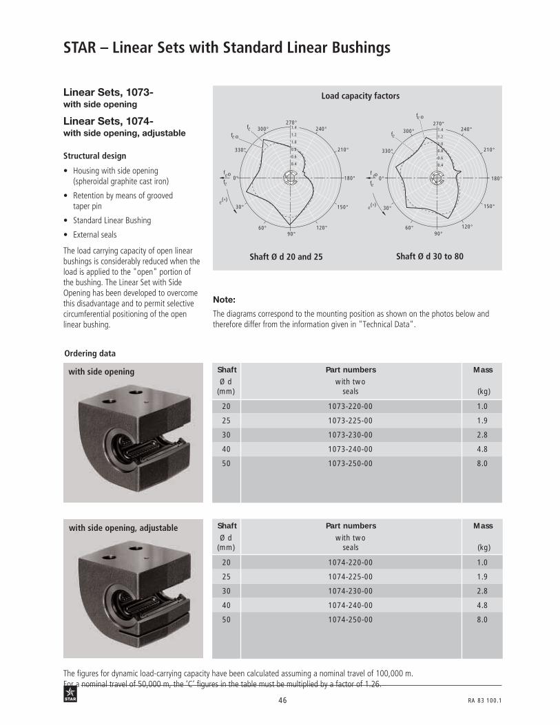
Structural design
• Housing with side opening(spheroidal graphite cast iron)
• Retention by means of groovedtaper pin
• Standard Linear Bushing
• External seals
Linear Sets, 1073-with side opening
Linear Sets, 1074-with side opening, adjustable
The load carrying capacity of open linearbushings is considerably reduced when theload is applied to the "open" portion ofthe bushing. The Linear Set with SideOpening has been developed to overcomethis disadvantage and to permit selectivecircumferential positioning of the openlinear bushing.
Note:
The diagrams correspond to the mounting position as shown on the photos below andtherefore differ from the information given in "Technical Data".
Load capacity factors
3N88 3N89
34 o 2
34 o 2
(°)
0°
30°
330°
270°240°
210°
180°
150°
120°90°
60°
300°f
f ο
f οf
1.2
1.0
0.8
0.6
1.4
0.4
Shaft Ø d 20 and 25 Shaft Ø d 30 to 80
f ο
(°) 30°
330°
270°240°
210°
180°
150°
120°90°
60°
300°f1.4
1.0
0.8
0.6
f ο
f0°
1.2
0.4
Ordering data
with side opening Shaft Part numbers Mass
Ø d with two(mm) seals (kg)
20 1073-220-00 1.0
25 1073-225-00 1.9
30 1073-230-00 2.8
40 1073-240-00 4.8
50 1073-250-00 8.0
with side opening, adjustable Shaft Part numbers Mass
Ø d with two(mm) seals (kg)
20 1074-220-00 1.0
25 1074-225-00 1.9
30 1074-230-00 2.8
40 1074-240-00 4.8
50 1074-250-00 8.0
The figures for dynamic load-carrying capacity have been calculated assuming a nominal travel of 100,000 m.For a nominal travel of 50,000 m, the ‘C’ figures in the table must be multiplied by a factor of 1.26.

RA 83 100.1 47
Dimensions
A
H
SW
W
V
H 1
E 1 N
O
R
D
d
L E 2
S
FO FO
FU FU
FH2FH1
Dimensions (mm) Angle Radial Tolerance Load capa-(°) clearance6) (µm) (µm) cities8) (N)
Ø d H H13) L3) A3) E1 E2 N D V S SW O4) W5) R3) a 1073-... 1074-... for dyn. stat.
with shaft dimension
C C0
h6 h7 H7)
202)
30 60 60 60 22±0.25 30±0.25 17 32 42 9 2.5 M8x60 10 37 60+36 +42 +5
1280 970+4 +6 –19
252)
35 72 73 75 28±0.25 36±0.25 21 40 50 11 3 M10x70 12.5 45 60+38 +44 +5
2270 1750+4 +6 –19
30 40 82 85 86 34±0.50 42±0.50 25 47 55 13.5 3 M12x80 12.5 51 50+38 +44 +5
2890 2390+4 +6 –19
40 45 100 97 110 43±0.50 48±0.50 32 62 67 15.5 4 M14x90 16.8 66 50+45 +52 +4
5280 4000+5 +7 –21
50 50 115 125 127 50±0.50 62±0.50 38 75 78 17.5 5 M16x110 21 77 50+45 +52 +8
8470 6900+5 +7 –25ad
just
ed p
rior
to d
eliv
ery
to z
ero
clea
r-an
ce o
n h5
sha
ft (l
ower
lim
it) w
hen
scre
wed
dow
n
1) Sizes 20 and 25: F0 = 0.85 · C0; FU = 1.27 · C0.2) In these sizes, the locating screw is on the opposite side to that shown in the illustration.3) Tolerance to DIN 1685-GTB 16.4) Hex. socket head cap screws to ISO 4762-8.8.5) Lower limit relative to shaft nominal dimension d.6) When screwed down.7) Relative to shaft nominal dimension d.8) The load capacities apply when the load is acting along the line = 0° in the direction shown by the arrows at FH1 or FH2.
Maximum permissible loads:F0 = 0.98 · C0
1) FU = C01)
FH1 = C0 FH2 = C0
42 o 2a 26 b3

48 RA 83 100.1
STAR – Linear Sets with Standard Linear Bushings
Ordering data
Shaft Part numbers Mass
Ø d with two(mm) seals (kg)
12 1081-212-00 0.11
16 1081-216-00 0.18
20 1081-220-00 0.33
25 1081-225-00 0.63
30 1081-230-00 1.00
40 1081-240-00 1.90
50 1081-250-00 4.00
60 1081-260-00 7.40
80 1081-280-00 14.70
Linear Sets, 1081-flanged type
Structural design
• Flanged housing (lamellar graphitecast iron)
• Two retaining rings, plus two spacerrings (steel) for sizes 12 to 40
• Standard Linear Bushings with wiperseals
• The radial clearance is not adjustable
34 o 3
The figures for dynamic load-carrying capacity have been calculated assuming a nominal travel of 100,000 m.For a nominal travel of 50,000 m, the ‘C’ figures in the table must be multiplied by a factor of 1.26.

RA 83 100.1 49
Dimensions
Dimensions Radial Load capa-(mm) clearance2) cities3) (N)
Ø d B1) L L1 D D1 D21) E S V1) W (µm) dyn. stat.
with shaft C C0+1 H13 h6 h7
12 42 32 12 22 24 28 30±0.12 5.5 6 10+20 +26
420 280+5 +6
16 50 36 15 26 28.5 34 35±0.12 5.5 8 10.5+22 +28
580 440+5 +6
20 60 45 18 32 35 42 42±0.15 6.6 10 13.5+23 +31
1170 860+6 +6
25 74 58 23 40 43 54 54±0.15 6.6 12 17.5+25 +32
2080 1560+6 +7
30 84 68 26 49.5 52 62 60±0.25 9.0 14 21+25 +32
2820 2230+6 +7
40 108 80 36 65 68 80 78±0.25 11 16 22+30 +38
5170 3810+7 +8
50 130 100 72 75 81 98 98±0.25 11 18 14+30 +38
8260 6470+7 +8
60 160 125 95 90 96 115 120±0.50 14 22 15+33 +43
11500 9160+7 +8
80 200 165 125 120 129 150 155±0.50 14 26 20+37 +47
21000 16300+8 +9
43 o 2 43 o 3
1) Tolerance to DIN 1686-GTB 15.2) Statistically determined from the working bore diameter and shaft tolerances. Taking the Linear Bushing outer diameter and the
housing bore into consideration, the radial clearance values for shaft h7 are similar to those given for the Standard Linear Bushing0610-... in the ¨h7/H7¨ column under the heading ¨Adjustable radial clearance¨.
3) The load capacities stated are minimum values as the position and direction of load cannot always be precisely defined.
E
B
E
S
B D2dD1
L 1
W V
L
D
50 RA 83 100.1
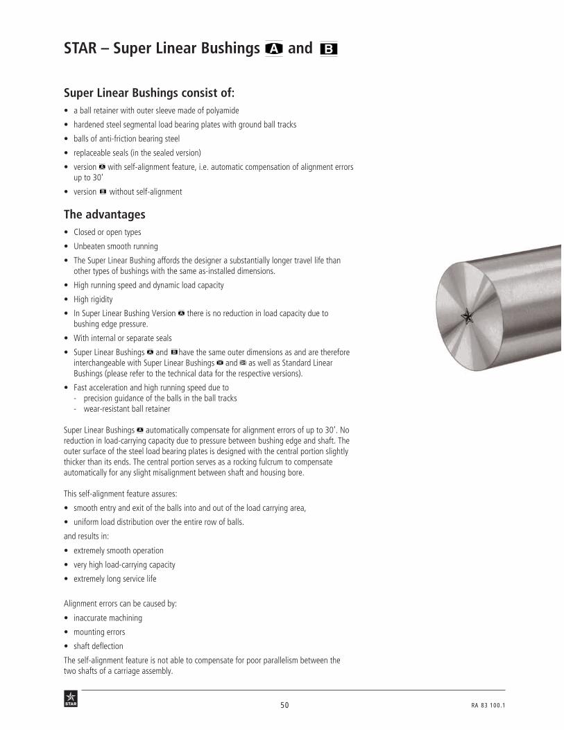
Super Linear Bushings consist of:• a ball retainer with outer sleeve made of polyamide
• hardened steel segmental load bearing plates with ground ball tracks
• balls of anti-friction bearing steel
• replaceable seals (in the sealed version)
• version with self-alignment feature, i.e. automatic compensation of alignment errorsup to 30’
• version without self-alignment
The advantages• Closed or open types
• Unbeaten smooth running
• The Super Linear Bushing affords the designer a substantially longer travel life thanother types of bushings with the same as-installed dimensions.
• High running speed and dynamic load capacity
• High rigidity
• In Super Linear Bushing Version there is no reduction in load capacity due tobushing edge pressure.
• With internal or separate seals
• Super Linear Bushings and have the same outer dimensions as and are thereforeinterchangeable with Super Linear Bushings and as well as Standard LinearBushings (please refer to the technical data for the respective versions).
• Fast acceleration and high running speed due to- precision guidance of the balls in the ball tracks- wear-resistant ball retainer
Super Linear Bushings automatically compensate for alignment errors of up to 30’. Noreduction in load-carrying capacity due to pressure between bushing edge and shaft. Theouter surface of the steel load bearing plates is designed with the central portion slightlythicker than its ends. The central portion serves as a rocking fulcrum to compensateautomatically for any slight misalignment between shaft and housing bore.
This self-alignment feature assures:
• smooth entry and exit of the balls into and out of the load carrying area,
• uniform load distribution over the entire row of balls.
and results in:
• extremely smooth operation
• very high load-carrying capacity
• extremely long service life
Alignment errors can be caused by:
• inaccurate machining
• mounting errors
• shaft deflection
The self-alignment feature is not able to compensate for poor parallelism between thetwo shafts of a carriage assembly.
STAR – Super Linear Bushings and

RA 83 100.1 51
02 N 1
Open type(Super )
Closed type(Super )
21o3
52 RA 83 100.1
Please observe the general technical principles and mounting instructions at the beginning of this catalog as well asthe additional technical data given below.
STAR – Super Linear Bushings and Technical Data
Sealing
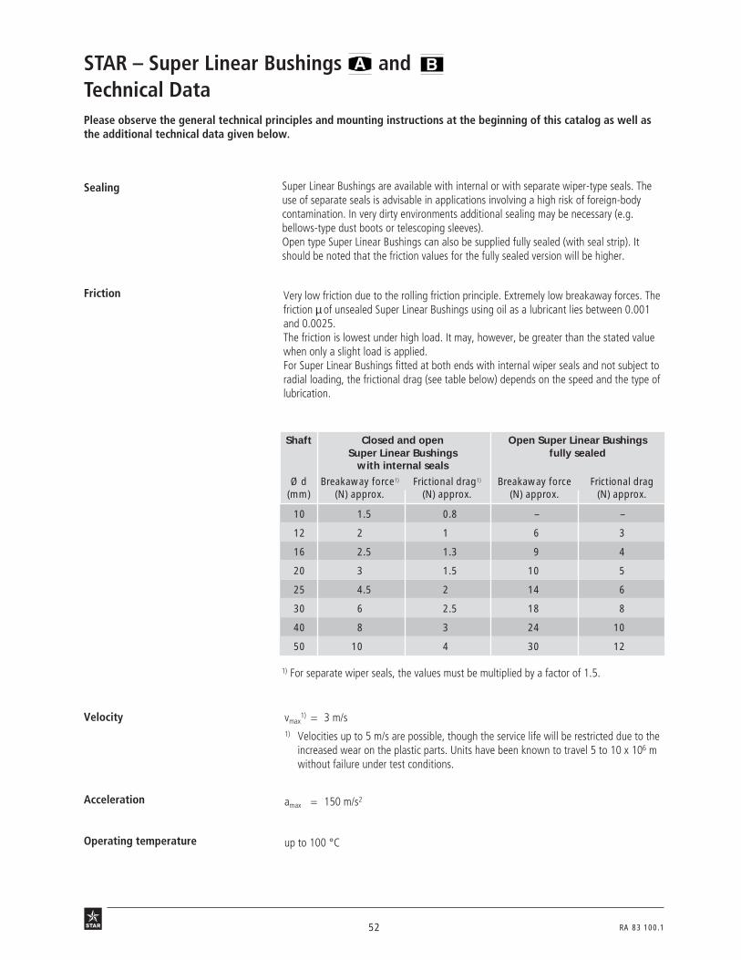
Operating temperature up to 100 °C
vmax1) = 3 m/s
1) Velocities up to 5 m/s are possible, though the service life will be restricted due to theincreased wear on the plastic parts. Units have been known to travel 5 to 10 x 106 mwithout failure under test conditions.
Velocity
Acceleration amax = 150 m/s2
Very low friction due to the rolling friction principle. Extremely low breakaway forces. Thefriction µ of unsealed Super Linear Bushings using oil as a lubricant lies between 0.001and 0.0025.The friction is lowest under high load. It may, however, be greater than the stated valuewhen only a slight load is applied.For Super Linear Bushings fitted at both ends with internal wiper seals and not subject toradial loading, the frictional drag (see table below) depends on the speed and the type oflubrication.
Friction
Shaft Closed and open Open Super Linear BushingsSuper Linear Bushings fully sealed
with internal seals
Ø d Breakaway force1) Frictional drag1) Breakaway force Frictional drag(mm) (N) approx. (N) approx. (N) approx. (N) approx.
10 1.5 0.8 – –
12 2 1 6 3
16 2.5 1.3 9 4
20 3 1.5 10 5
25 4.5 2 14 6
30 6 2.5 18 8
40 8 3 24 10
50 10 4 30 12
Super Linear Bushings are available with internal or with separate wiper-type seals. Theuse of separate seals is advisable in applications involving a high risk of foreign-bodycontamination. In very dirty environments additional sealing may be necessary (e.g.bellows-type dust boots or telescoping sleeves).Open type Super Linear Bushings can also be supplied fully sealed (with seal strip). Itshould be noted that the friction values for the fully sealed version will be higher.
1) For separate wiper seals, the values must be multiplied by a factor of 1.5.

RA 83 100.1 53
The stated load capacities are valid for installation in "min" position and should be takenas the basis for calculation.In applications where the direction of load is exactly known and where the Super LinearBushings can be mounted in the "max" position, the load capacity rating must be multi-plied by the factors fmax (dynamic load capacity C) or f0 max (static load capacity C0).
max.min.
10 B 2
Shaft Load capacity
Ø d factors
(mm) fmax f0 max
10, 12, 16 1.19 1.46
20, 25, 30, 40, 50 1.06 1.28
Load capacity factors
The load capacities C and C0 apply only when the load is acting along the line = 0°. Ifthe load is acting in any other direction, these load capacities must be multiplied by thefactor f (dynamic load capacity C) or f 0 (static load capacity C0) .A reduction in load capacity can be eliminated by selective circumferential positioning ofthe Super Linear Bushing (see Linear Set with Side Opening).
Shaft Ø d 12 and 16 Shaft Ø d 20 to 50
(°)0°
30° 330°
270°
240°
210°
180°
150°
120°
90°
60° 300°
f οf
f ο
f
0.4
1.2
1.0
0.8
0.6
1.4
f οf
0°
30°
300°
270°
240°
210°
180°
150°
120°
90°
60°
330°f ο
f
(°)
1.4
1.0
0.8
0.6
1.2
0.4
12 B 1 12 B 2
Direction of load and its influenceon the load capacity of closedSuper Linear Bushings
Direction of load and its influenceon the load capacity of openSuper Linear Bushings

54 RA 83 100.1
0
2.5
5.0
7.5
0
2.5
5.0
7.
T
STAR – Super Linear Bushings and Technical Data
In short-stroke applications, the service life of the shafts is shorter than that of the SuperLinear Bushings.
Reduced load capacity inshort-stroke applications
Reduced load capacity at high loads If the load acting on Super Linear Bushing is F > 0.5 x C, there will be a reduction in thedynamic load capacity C. At load F = C0, the load capacity C has to be multiplied by theload factor fF = 0.93.
12 B 3
06 B 1
Self-alignment feature inSuper Linear Bushing
The self-alignment feature together with the ground-quality finish of the ball tracks resultin extremely smooth operation. The running diagrams below show a comparison with aconventional linear bearing for a load of 800 N and an alignment error of about 8’ (due toshaft deflection).
Super Linear Bushing Conventional linear bearingShaft Ø d 20 Shaft Ø d 20
Speed of travel 0.3 mm/s
Operation underdifficult conditions
When this type is used, the self-alignment feature requires two Super Linear Bushings tobe mounted on at least one of the two shafts of the assembly.
For applications involving water-base coolants/lubricants, we recommend the use of thefollowing linear bushing models:
- Super Linear Bushings and
- Standard Linear Bushings
In permanently humid or wet environments (water vapor, condensation), we recommendthe use of the following corrosion-resistant linear bushing models:
- Segmental Linear Bushings or
- Compact Linear Bushings
with steel parts made of corrosion-resistant steel to DIN 17230 / EN 10088.
Stroke (mm)
Frict
iona
l dra
g (N
)
Frict
iona
l dra
g (N
)
Travel
For this reason, the load capacities C listed in the tables must be multiplied by the factor fw.
0 20 40 60 80 100 120 140
1.0
0.5
0.6
0.7
0.8
0.9
fw
160 180 200 220 240 260
5010
16
12
2025 30 40
Travel

RA 83 100.1 55
Notes for Mounting
The radial clearance values given in the tables have been obtained by statistical methodsand are representative of the clearances to be expected in actual practice.
The radial clearance is adjustable in all types of Super Linear Bushings.If an application calls for zero clearance, the radial clearance must be reduced by meansof an adjusting screw in the bushing housing (see also Linear Sets) until a slight resistanceis felt when the shaft is turned. In applications subject to vibration, the adjusting screwshould be suitably secured against working loose once the desired clearance has beenestablished.
If negative clearance (preload) is required, we recommend that zero clearance should beestablished as described above using a dummy shaft whose diameter is smaller by theamount of the desired preload than the actual guide shaft on which the linear bushing isto run.
Radial clearance
Adjusting the radial clearance
Preload

56 RA 83 100.1
Lube groove and lube hole forSuper Linear Bushings , ,closed type – with external seals
STAR – Super Linear Bushings and Customer-Built Housings
Linear Bushing with Shaft Dimensions (mm)separate seals diameter
Part numbers d
(mm) L1 H1 L (min) D D1 I J
0670-210-00 0672-210-00 10 7.5 6 36 19 – 3 11.5
0670-212-00 0672-212-00 12 9 8 39 22 – 5 13
0670-216-00 0672-216-00 16 10 12 43 26 – 5 18
0670-220-00 0672-220-00 20 13.5 15 54 32 – 2 15.5
0670-225-00 0672-225-00 25 18.5 20 67 40 42 – –
0670-230-00 0672-230-00 30 23.5 23.5 79 47 49 – –
0670-240-00 0672-240-00 40 27.5 31 91 62 66 – –
0670-250-00 0672-250-00 50 34.5 37.5 113 75 79 – –
The lube channels shown in the illustration have been designed for grease lubricants.
Shaft Ø10, 12, 16, 20
Shaft Ø25, 30, 40, 50
3 N 105
D1
45°
45°
L
L/2
A L/2
L 17
A
L
L/2
AL/2
A
L 1
D
ØI
J
A—A
Ø7M8x1
H1
min.6D
Ø7M8x1
H1
min.6
A—A

RA 83 100.1 57
Lube groove and lube hole forSuper Linear Bushings , ,open type – with external seals
Ø7M8x1
H1
A—A
D
J
ØI
G GF F
ØI
A—A
Ø7M8x1
H1
min.6
D
J
D1
45°
45°
L
L/2
A L/2
L 17
A
L
L/2
AL/2
A
L 1
min.6
The lube channels shown in the illustration have been designed for grease lubricants. Seals must be secured axially.
Shaft Ø25, 30, 40, 50
Shaft Ø12, 16, 20
3 N 106
Linear Bushing with Shaft Dimensions (mm)separate seals diameter
Part numbers d
(mm) L1 H1 L (min) D D1 F G I J
0671-212-00 0673-212-00 12 9 8 39 22 – – – 2 13
0671-216-00 0673-216-00 16 10 12 43 26 – – – 2 14
0671-220-00 0673-220-00 20 13.5 15 54 32 – – – 2 16
0671-225-00 0673-225-00 25 18.5 20 67 40 42 R 15 4 7 –
0671-230-00 0673-230-00 30 23.5 23.5 79 47 49 R 18 4.5 7 –
0671-240-00 0673-240-00 40 27.5 31 91 62 66 R 23 6 7 –
0671-250-00 0673-250-00 50 34.5 37.5 113 75 79 R 28 7 4 30

58 RA 83 100.1
STAR – Super Linear Bushings and Customer-Built HousingsRetentionSuper Linear Bushings
closed type
• Retaining rings
• Metal case
• Seal with metal case
• Special arrangementRetention by means of retainingrings to DIN 471
Retention by means of retainingrings to DIN 472
15 B 1 15 B 3
Shaft Retaining rings DIN 471 Retaining rings DIN 472
Ø d Part numbers Dimensions Part numbers Dimensions(mm) (mm) (mm)
10 8410-763-00 19 x 1.2 8410-221-00 19 x 1
12 8410-714-00 22 x 1.2 8410-209-00 22 x 1
16 8410-715-00 27 x 1.21) 8410-210-00 26 x 1.2
20 8410-716-00 33 x 1.51) 8410-211-00 32 x 1.2
25 8410-717-00 42 x 1.75 8410-212-00 40 x 1.75
30 8410-718-00 48 x 1.75 8410-213-00 47 x 1.75
40 8410-719-00 62 x 2 8410-214-00 62 x 2
50 8410-720-00 75 x 2.5 8410-215-00 75 x 2.5
Separate seals Materials: elastomer seal, steel case
1) not to DIN 471
Axial retention by means of screwsand cover plates
15 B 4 15 B 6
Seal with metal case (closed type) Shaft Dimensions (mm) Part numbers
Ø d D2) b seal with metal case
(mm) +0.3 metal case
10 19 3 1331-610-00 0901-184-00
12 22 3 1331-612-00 0901-074-00
16 26 3 1331-616-00 0901-075-00
20 32 4 1331-620-00 0901-076-00
25 40 4 1331-625-00 0901-077-00
30 47 5 1331-630-00 0901-078-00
40 62 5 1331-640-00 0901-079-00
50 75 6 1331-650-00 0901-115-00
11 b 1 2) The outside diameter D has been manufactured with an oversize of approx. 0.1 mm.No additional retention required.
Retention by means of metal caseRetention by means of seal withmetal case
Dd
b
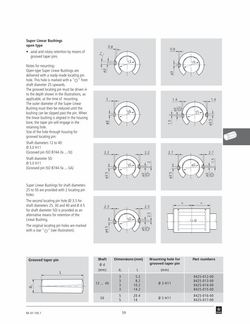
RA 83 100.1 59
Super Linear Bushingsopen type
• axial and rotary retention by means ofgrooved taper pins
Notes for mounting:Open-type Super Linear Bushings aredelivered with a ready-made locating pinhole. This hole is marked with a " " fromshaft diameter 25 upwards.The grooved locating pin must be driven into the depth shown in the illustrations, asapplicable, at the time of mounting.The outer diameter of the Super LinearBushing must then be reduced until thebushing can be slipped past the pin. Whenthe linear bushing is aligned in the housingbore, the taper pin will engage in theretaining hole.Size of the hole through housing forgrooved locating pin:
Shaft diameters 12 to 40:Ø 3.0 H11(Grooved pin ISO 8744-3x ...-St)
Shaft diameter 50:Ø 5.0 H11(Grooved pin ISO 8744-5x ...-SA)
Super Linear Bushings for shaft diameters25 to 50 are provided with 2 locating pinholes.
The second locating pin hole (Ø 3.5 forshaft diameters 25, 30 and 40 and Ø 4.5for shaft diameter 50) is provided as analternative means for retention of theLinear Bushing.
The original locating pin holes are markedwith a star " " (see illustration).
1
20ø3
2.7
40
2.7
ø3.5 ø3
1.5
2.2
30
2.2
ø3.5 ø3
2
2.3
50
2.3
ø4.5 ø5
2.5
= =
0.8
12
7°
ø3
0.8
16
ø3
Grooved taper pin Shaft Dimensions (mm) Mounting hole for Part numbers
Ø d grooved taper pin
(mm) d1 L (mm)
3 5.2 8425-012-00
12 … 403 8.2
Ø 3 H118425-013-00
3 10.2 8425-014-003 14.2 8425-015-00
505 20.4
Ø 5 H118425-016-00
5 14 8425-017-00
16 B 1 16 B 2
16 B 3 16 B 4
16 B 5 16 B 6
16 B 7 16 B 8
L
d1
1.4
25ø3
1.5
1.4
ø3.5

60 RA 83 100.1
STAR – Super Linear Bushings and Customer-Built Housings• axial and rotary retention by means of
locating screw
Points to note when mounting:Open type Standard Linear Bushings havebeen provided with the necessary retentionhole. This hole is marked with a " " fromshaft diameter 25 upwards.On installation, the retention hole of theLinear Bushing must be aligned with thetapped hole in the housing. The screw isthen inserted, screwed down to thespecified depth and tightened to thespecified torque.
L
d
7°
L
d
d = 12 d = 16, 20
3 N 206 3 N 200
L
d
K 2
L
d
K2
d = 25 d = 30, 40, 50
3 N 202
3 N 201
= = L4
ø 0.05
D4 D3 D2
L3
L2
D1
L1
L
Shaft Dimensions (mm) Locating screw Ø d L K2 L1 L2 L3 L4 D1 D2 D3 D4 Tightening
Part numbers torque(mm) min. +0.2 min. +0.1 H13 H13 (Nm)
12 18.8–0.1 – 7.2max 5.2 1.3 2.5 3.1 M4 4.5 8 8429-008-01 1.9
16 22.5–0.1 0 8.5+0.2 6.5 1.3 2.5 3.1 M4 4.5 8 8429-009-01 1.9
20 25.5–0.1 0 8.5+0.2 6.5 1.3 2.5 3.1 M4 4.5 8 8429-009-01 1.9
25 33.05–0.1 1.5 10+0.2 8 2 3.2 3.1 M4 4.5 8 8427-009-09 1.9
30 36–0.15 2 10+0.2 8 2 3.2 3.1 M4 4.5 8 8427-009-09 1.9
40 42.9–0.15 1.5 10+0.2 8 2 3.2 3.1 M4 4.5 8 8427-009-09 1.9
50 58.5–0.2 2.5 17.5+0.5 13.5 3.7 6 5.1 M8 9 15 8427-005-09 16
16 B 8
3 N 203

RA 83 100.1 61
dk
d1
d
kl1
ls
Locating screwsfor shaft Ø 25, 30, 40, 50
s
dk
d1
d
kl1
l
for shaft Ø 12, 16, 20
3 N 204 3 N 205
Shaft Part Dimensions (mm) Tighteningnumbers torque
Ø d(mm) d dk d1 l l1 k s (Nm)
12 8429-008-01 M4 7.6 3 8.45 4.5 2.2 2.5 1.9
16, 20 8429-009-01 M4 7.6 3 10.15 5.7 2.2 2.5 1.9
25, 30, 40 8427-009-09 M4 7 3 14.1 6.5 2.8 2.5 1.9
50 8427-005-09 M8 13 5 22.8 12.5 5 5 16The locating screws are of the self-lockingtype.
11 b 2
seal with metal case (open type)
Separate seals
Shaft Dimensions (mm) Angle (°) Part numbers
Ø d D1) b α2) Seal with(mm) +0.1 metal case
–0.2
12 22 3 66 1331-712-50
16 26 3 68 1331-716-50
20 32 4 55 1331-720-50
25 40 4 57 1331-725-50
30 47 5 57 1331-730-50
40 62 5 56 1331-740-50
50 75 6 54 1331-750-50
b D
d
1) Outside diameter D is about 0.3 mm oversize. No retaining elements required. Additio-nal means of retention recommended for applications subject to vibration or highacceleration rates.
2) Lower limit, measured when mounted in a bore of nominal diameter D.
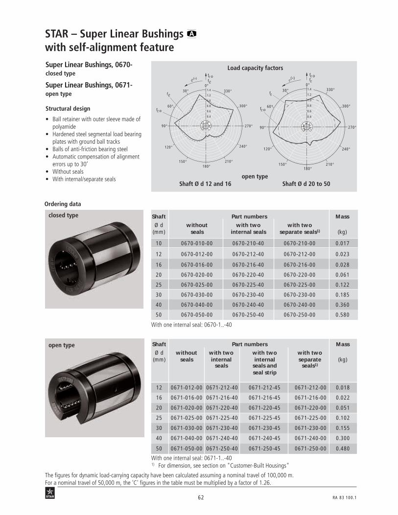
62 RA 83 100.1
Super Linear Bushings, 0670-closed type
Super Linear Bushings, 0671-open type
Shaft Part numbers Mass
Ø d without with two with two with two(mm) seals internal internal separate (kg)
seals seals and seals1)
seal strip
12 0671-012-00 0671-212-40 0671-212-45 0671-212-00 0.018
16 0671-016-00 0671-216-40 0671-216-45 0671-216-00 0.022
20 0671-020-00 0671-220-40 0671-220-45 0671-220-00 0.051
25 0671-025-00 0671-225-40 0671-225-45 0671-225-00 0.102
30 0671-030-00 0671-230-40 0671-230-45 0671-230-00 0.155
40 0671-040-00 0671-240-40 0671-240-45 0671-240-00 0.300
50 0671-050-00 0671-250-40 0671-250-45 0671-250-00 0.480
With one internal seal: 0671-1..-401) For dimension, see section on "Customer-Built Housings"
With one internal seal: 0670-1..-40
Shaft Part numbers Mass
Ø d without with two with two(mm) seals internal seals separate seals1) (kg)
10 0670-010-00 0670-210-40 0670-210-00 0.017
12 0670-012-00 0670-212-40 0670-212-00 0.023
16 0670-016-00 0670-216-40 0670-216-00 0.028
20 0670-020-00 0670-220-40 0670-220-00 0.061
25 0670-025-00 0670-225-40 0670-225-00 0.122
30 0670-030-00 0670-230-40 0670-230-00 0.185
40 0670-040-00 0670-240-40 0670-240-00 0.360
50 0670-050-00 0670-250-40 0670-250-00 0.580
Structural design
• Ball retainer with outer sleeve made ofpolyamide
• Hardened steel segmental load bearingplates with ground ball tracks
• Balls of anti-friction bearing steel• Automatic compensation of alignment
errors up to 30’• Without seals• With internal/separate seals
STAR – Super Linear Bushings with self-alignment feature
Ordering data
closed type
Load capacity factors
0°30° 330°
270°
240°
210°180°
150°
120°
90°
60° 300°
0.4
1.2
1.0
0.8
0.6
1.4
f(°)
f
f ο
f ο
f οf(°)
0°30°
300°
270°
240°
210°180°
150°
120°
90°
60°
330°
f ο
f 1.2
1.0
0.8
0.6
1.4
0.4
12 B 1 12 B 2
19 o 1r
19 o 2r
open typeShaft Ø d 12 and 16 Shaft Ø d 20 to 50
The figures for dynamic load-carrying capacity have been calculated assuming a nominal travel of 100,000 m.For a nominal travel of 50,000 m, the 'C' figures in the table must be multiplied by a factor of 1.26.
open type
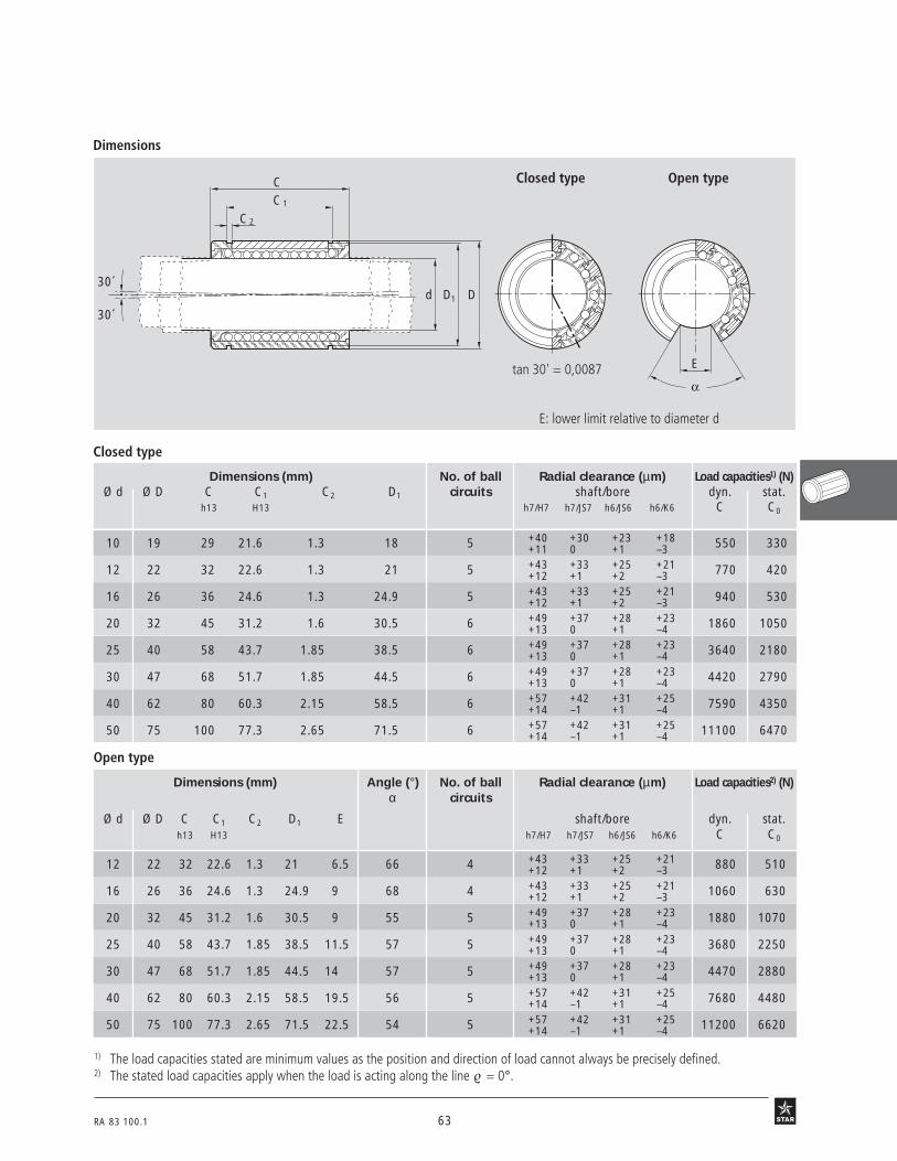
RA 83 100.1 63
Dimensions
Open type
Dimensions (mm) Angle (°) No. of ball Radial clearance (µm) Load capacities2) (N)α circuits
Ø d Ø D C C1 C2 D1 E shaft/bore dyn. stat.h13 H13 h7/H7 h7/JS7 h6/JS6 h6/K6 C C0
12 22 32 22.6 1.3 21 6.5 66 4 +43 +33 +25 +21 880 510+12 +1 +2 –3
16 26 36 24.6 1.3 24.9 9 68 4 +43 +33 +25 +21 1060 630+12 +1 +2 –3
20 32 45 31.2 1.6 30.5 9 55 5 +49 +37 +28 +23 1880 1070+13 0 +1 –4
25 40 58 43.7 1.85 38.5 11.5 57 5 +49 +37 +28 +23 3680 2250+13 0 +1 –4
30 47 68 51.7 1.85 44.5 14 57 5 +49 +37 +28 +23 4470 2880+13 0 +1 –4
40 62 80 60.3 2.15 58.5 19.5 56 5 +57 +42 +31 +25 7680 4480+14 –1 +1 –4
50 75 100 77.3 2.65 71.5 22.5 54 5 +57 +42 +31 +25 11200 6620+14 –1 +1 –4
1) The load capacities stated are minimum values as the position and direction of load cannot always be precisely defined.2) The stated load capacities apply when the load is acting along the line = 0°.
30´
30´
D
C
1C
D1
C2
d
E: lower limit relative to diameter d
tan 30' = 0,0087
08 b 1 08 b 2
Closed type Open type
Closed type
Dimensions (mm) No. of ball Radial clearance (µm) Load capacities1) (N)Ø d Ø D C C1 C2 D1 circuits shaft/bore dyn. stat.
h13 H13 h7/H7 h7/JS7 h6/JS6 h6/K6 C C0
10 19 29 21.6 1.3 18 5 +40 +30 +23 +18 550 330+11 0 +1 –3
12 22 32 22.6 1.3 21 5 +43 +33 +25 +21 770 420+12 +1 +2 –3
16 26 36 24.6 1.3 24.9 5 +43 +33 +25 +21 940 530+12 +1 +2 –3
20 32 45 31.2 1.6 30.5 6 +49 +37 +28 +23 1860 1050+13 0 +1 –4
25 40 58 43.7 1.85 38.5 6 +49 +37 +28 +23 3640 2180+13 0 +1 –4
30 47 68 51.7 1.85 44.5 6 +49 +37 +28 +23 4420 2790+13 0 +1 –4
40 62 80 60.3 2.15 58.5 6 +57 +42 +31 +25 7590 4350+14 –1 +1 –4
50 75 100 77.3 2.65 71.5 6 +57 +42 +31 +25 11100 6470+14 –1 +1 –4
E

64 RA 83 100.1
Super Linear Bushings, 0672-closed type
Super Linear Bushings, 0673-open type
Structural design
• Ball retainer with outer sleeve madeof polyamide
• Hardened steel segmental load bearingplates with ground ball tracks
• Balls of anti-friction bearing steel
• Without seals
• With internal/separate seals
STAR – Super Linear Bushings without self-alignment feature
21o1 r
21o3 r
With one internal seal: 0673-1..-401) For dimension, see section on "Customer-Built Housings"
Ordering data
closed type
open type
Shaft Part numbers Mass
Ø d without with two with two(mm) seals internal seals separate seals1) (kg)
10 0672-010-00 0672-210-40 0672-210-00 0.017
12 0672-012-00 0672-212-40 0672-212-00 0.023
16 0672-016-00 0672-216-40 0672-216-00 0.028
20 0672-020-00 0672-220-40 0672-220-00 0.061
25 0672-025-00 0672-225-40 0672-225-00 0.122
30 0672-030-00 0672-230-40 0672-230-00 0.185
40 0672-040-00 0672-240-40 0672-240-00 0.360
50 0672-050-00 0672-250-40 0672-250-00 0.580
Shaft Part numbers Mass
Ø d without with two with two with two(mm) seals internal internal separate (kg)
seals seals and seals1)
seal strip
12 0673-012-00 0673-212-40 0673-212-45 0673-212-00 0.018
16 0673-016-00 0673-216-40 0673-216-45 0673-216-00 0.022
20 0673-020-00 0673-220-40 0673-220-45 0673-220-00 0.051
25 0673-025-00 0673-225-40 0673-225-45 0673-225-00 0.102
30 0673-030-00 0673-230-40 0673-230-45 0673-230-00 0.155
40 0673-040-00 0673-240-40 0673-240-45 0673-240-00 0.300
50 0673-050-00 0673-250-40 0673-250-45 0673-250-00 0.480
12 B 1 12 B 2
Open typeShaft Ø d 12 and 16 Shaft Ø d 20 to 50
0°30° 330°
270°
240°
210°180°
150°
120°
90°
60° 300°
0.4
1.2
1.0
0.8
0.6
1.4
f(°)
f
f ο
f ο
Load capacity factorsf οf(°)
0°30°
300°
270°
240°
210°180°
150°
120°
90°
60°
330°
f ο
f 1.2
1.0
0.8
0.6
1.4
0.4
The figures for dynamic load-carrying capacity have been calculated assuming a nominal travel of 100,000 m.For a nominal travel of 50,000 m, the ‘C’ figures in the table must be multiplied by a factor of 1.26.
With one internal seal: 0672-1..-40

RA 83 100.1 65
Dimensions09 b 1
Closed type
Dimensions (mm) Angle (°) No. of ball Radial clearance (µm) Load capacities2) (N)α circuits
Ø d Ø D C C1 C2 D1 E shaft/bore dyn. stat.h13 H13 h7/H7 h7/JS7 h6/JS6 h6/K6 C C0
12 22 32 22.6 1,3 21 6,5 66 4 +43 +33 +25 +21 880 510+12 +1 +2 –3
16 26 36 24.6 1.3 24.9 9 68 4 +43 +33 +25 +21 1060 630+12 +1 +2 –3
20 32 45 31.2 1.6 30.5 9 55 5 +49 +37 +28 +23 1880 1070+13 0 +1 –4
25 40 58 43.7 1.85 38.5 11.5 57 5 +49 +37 +28 +23 3680 2250+13 0 +1 –4
30 47 68 51.7 1.85 44.5 14 57 5 +49 +37 +28 +23 4470 2880+13 0 +1 –4
40 62 80 60.3 2.15 58.5 19.5 56 5 +57 +42 +31 +25 7680 4480+14 –1 +1 –4
50 75 100 77.3 2.65 71.5 22.5 54 5 +57 +42 +31 +25 11200 6620+14 –1 +1 –4
1) The load capacities stated are minimum values as the position and direction of load cannot always be precisely defined.2) The stated load capacities apply when the load is acting along the line = 0°.
E: lower limit relative to diameter d
dD D1
C
1C
C 2
E
Open type
Closed type Open type
Dimensions (mm) No. of ball Radial clearance (µm) Load capacities1) (N)circuits
Ø d Ø D C C1 C2 D1 shaft/bore dyn. stat.h13 H13 h7/H7 h7/JS7 h6/JS6 h6/K6 C C0
10 19 29 21.6 1.3 18 5 +40 +30 +23 +18 550 330+11 0 +1 –3
12 22 32 22.6 1.3 21 5 +43 +33 +25 +21 770 420+12 +1 +2 –3
16 26 36 24.6 1.3 24.9 5 +43 +33 +25 +21 940 530+12 +1 +2 –3
20 32 45 31.2 1.6 30.5 6 +49 +37 +28 +23 1860 1050+13 0 +1 –4
25 40 58 43.7 1.85 38.5 6 +49 +37 +28 +23 3640 2180+13 0 +1 –4
30 47 68 51.7 1.85 44.5 6 +49 +37 +28 +23 4420 2790+13 0 +1 –4
40 62 80 60.3 2.15 58.5 6 +57 +42 +31 +25 7590 4350+14 –1 +1 –4
50 75 100 77.3 2.65 71.5 6 +57 +42 +31 +25 11100 6470+14 –1 +1 –4

66 RA 83 100.1
Super Linear Bushings with self-alignment feature
Super Linear Bushings without self-alignment feature
Aluminum Cast ironhousing housing
Super Linear Bushings with self-alignment feature
Aluminum housing
Linear Sets Tandem Linear Sets
1035-...
1036-...
1037-...
1038-...
1071-...
1072-...
1065-...
1066-...
1067-...
1068-...
1073-...
1074-...
1081-...
1085-...
1032-...
1087-...
1034-...
1083-...
STAR – Linear Sets with Super Linear Bushings or Overview
With side openingTakes up forces from all directions withoutreduction of load capacity.
With side opening, adjustableFor use when zero clearance or preload isrequired. The desired radial clearance isestablished by means of an adjustingscrew. These Linear Sets are adjustedto zero clearance before delivery.
Flanged type
This element was developed as a com-plement to our Linear Set series for use inapplications requiring the shaft to bearranged at right angles to the mountingbase.
Open type, adjustableFor use when zero clearance or preload isrequired. The desired radial clearance isestablished by means of an adjustingscrew. These Linear Sets are adjustedto zero clearance before delivery.
Adjustable typeFor use when zero clearance or preload isrequired. The desired radial clearance isestablished by means of an adjustingscrew. These Linear Sets are adjustedto zero clearance before delivery.
Open type
For long guideways when the shafts mustbe supported and high rigidity is required.
Closed typeFor high-precision guidance with extremeease of mounting. Version with fixedworking bore diameter.

RA 83 100.1 67
These Linear Sets afford high rigidity irrespective of the direction of load action and evenwhen their high load-carrying capacities are utilized to the full.
The Super Linear Bushing is completely enclosed in the compact housing to protect itagainst all external impacts.Tapped through-holes make it possible to insert the screws from above or below.A fitting edge along the block facilitates lining up during installation and prevents mis-alignment of the assembly. Center-bores are provided for the user to drill locating pinholes for extra stability.
Advantages/Mounting Instructions
AdvantagesHigh load capacity and rigidity
Notes on mounting of Linear Setswith side opening
Without fitting edge • Align first shaft mounted on shaft sup-port rail and screw down support rail.
• Align second shaft to ensure parallelismand screw down support rail.
• Push Linear Sets onto shafts and screwdown on the machine table.
• Push first shaft mounted on shaftsupport rail into contact with fittingedge and screw down support rail.
• Align second shaft to ensure parallelismand screw down support rail.
• Push Linear Sets onto the shafts.Further assembly:
27 b 5
27 b 6
Lubrication Whether grease is being applied for the first time or in-service, the shaft must always beinserted in the bushing. Add grease until the lubricant emerges.
The housing design and the integral Super Linear Bushing ensure high precision andfunctional reliability.
Zero-clearance The adjustable versions can be used to achieve zero clearance assemblies.
Mounting instructionsRadial clearance The radial clearance values given in the tables have been obtained by statistical methods
and are representative of the values to be expected in actual practice.Adjustable types of Linear Sets are adjusted to zero clearance (when screwed down) ona shaft of diameter accurate to a tolerance of h5 (lower limit) before leaving the factory.
Vertical dimensions The tables for Linear Sets contain tolerance values for the height dimension ‘H’. Thesetolerance values have been obtained by statistical methods and are representative of thevalues to be expected in actual practice.
Screws We recommend screws to ISO 4762-8.8 for mounting Linear Sets.
These Linear Sets are resistant to temperatures up to 100 °C.
Compact block design and ease ofmounting in the aluminum version
High precision and reliability
Operating temperatures
With fitting edge
a) With two fitting edges (one onmachine base and one on table):Push the Linear Sets on the first shaftinto contact with the fitting edge onthe machine table and screw down.Screw down the Linear Sets on thesecond shaft to the machine table.
b) With only one fitting edge (on themachine base):Screw Linear Sets down to the machinetable.

68 RA 83 100.1
Shaft Part numbers Mass
Ø d with Super Linear Bushing with Super Linear Bushing (mm) lubricatable lubricatable (kg)
with two seals with two seals
10 1035-610-20 1035-810-20 0.10
12 1035-612-20 1035-812-20 0.13
16 1035-616-20 1035-816-20 0.20
20 1035-620-20 1035-820-20 0.34
25 1035-625-20 1035-825-20 0.65
30 1035-630-20 1035-830-20 0.97
40 1035-640-20 1035-840-20 1.80
50 1035-650-20 1035-850-20 3.00
Linear Sets, 1035-closed type
Linear Sets, 1036-adjustable
Shaft Part numbers Mass
Ø d with Super Linear Bushing with Super Linear Bushing (mm) lubricatable lubricatable (kg)
with two seals with two seals
10 1036-610-20 1036-810-20 0.10
12 1036-612-20 1036-812-20 0.13
16 1036-616-20 1036-816-20 0.20
20 1036-620-20 1036-820-20 0.34
25 1036-625-20 1036-825-20 0.65
30 1036-630-20 1036-830-20 0.97
40 1036-640-20 1036-840-20 1.80
50 1036-650-20 1036-850-20 3.00
STAR – Linear Sets with Super Linear Bushings or
Structural design
• Precision Housing, lightweight series(aluminum)
• Super Linear Bushing with or withoutself-alignment feature
• External seals
• Fully sealed
• Lubricatable
Ordering data
closed type
adjustable
20 b 1r
20 b 2r
The figures for dynamic load-carrying capacity have been calculated assuming a nominal travel of 100,000 m.For a nominal travel of 50,000 m, the 'C' figures in the table must be multiplied by a factor of 1.26.

RA 83 100.1 69
Dimensions
Lube port
AM
S 1
S
N2V
HN1
X
H445 °
20 b 3 20 b 4 20 b 5
Dimensions (mm)
Ø d D H1) H1 M1) A L E1 E2 E3 E4 S2) S1 S23) N1 N2 H3 L3 V SW H4
+0.008 ±0.01–0.016
10 19 16 31.5 20 40 36 29±0.15 20±0.15 31 29 4.3 M5 4 15 11 10 10.5 5 2.5 10
12 22 18 35 21.5 43 39 32±0.15 23±0.15 34 32 4.3 M5 4 16.5 11 10 10.5 5 2.5 10
16 26 22 42 26.5 53 43 40±0.15 26±0.15 42 35 5.3 M6 4 21 13 10 11.5 5 3 13
20 32 25 50 30 60 54 45±0.15 32±0.15 50 45 6.6 M8 5 24 18 10 13.5 5 4 16
25 40 30 60 39 78 67 60±0.15 40±0.15 64 20 8.4 M10 6 29 22 10 15 6.5 5 20
30 47 35 70 43.5 87 79 68±0.15 45±0.15 72 30 8.4 M10 6 34 22 11.5 16 8 5 22
40 62 45 90 54 108 91 86±0.15 58±0.15 90 35 10.5 M12 8 44 26 14 18 10 6 28
50 75 50 105 66 132 113 108±0.20 50±0.20 108 42 13.5 M16 10 49 34 12.5 22 12 8 37
Radial clearance (µm) Load capacities4) (N)
Ø d 1035- 1036- dyn. stat.
(mm) shaft C C0h6 h7
10 +36 +40 550 330+9 +11
12 +38 +43 770 420+10 +12
16 +38 +43 940 530+10 +12
20 +43 +49 1860 1050+11 +13
25 +43 +49 3640 2180+11 +13
30 +43 +49 4420 2790+11 +13
40 +50 +57 7590 4350+12 +14
50 +50 +57 11100 6470+12 +14
H1
SW
L
L 3
M8x1D d
H3
S 2
E 4
E 3
E 2
E 1
X
adju
sted
prio
r to
deliv
eryt
o ze
ro c
lear
ance
on
h5 s
haft
(low
er li
mit)
whe
n sc
rew
ed d
own
1) When screwed down, relative to shaft nominal dimension d.2) Mounting screws to ISO 4762-8.83) Center-bores for locating pin holes4) The load capacities stated are minimum values as the position
and direction of load cannot always be precisely defined.

70 RA 83 100.1
Linear Sets, 1037-open type
Linear Sets, 1038-open type, adjustable
STAR – Linear Sets with Super Linear Bushings or
Structural design
• Precision Housing, lightweight series(aluminum)
• Retention by means of groovedtaper pin
• Super Linear Bushing with or withoutself-alignment feature
• External seals
• Lubricatable
Load capacity factors
Shaft Part numbers Mass
Ø d with Super Linear Bushing with Super Linear Bushing (mm) lubricatable lubricatable (kg)
with two seals with two seals
12 1037-612-20 1037-812-20 0.11
16 1037-616-20 1037-816-20 0.17
20 1037-620-20 1037-820-20 0.30
25 1037-625-20 1037-825-20 0.57
30 1037-630-20 1037-830-20 0.86
40 1037-640-20 1037-840-20 1.60
50 1037-650-20 1037-850-20 2.60
Shaft Part numbers Mass
Ø d with Super Linear Bushing with Super Linear Bushing (mm) lubricatable lubricatable (kg)
with two seals with two seals
12 1038-612-20 1038-812-20 0.11
16 1038-616-20 1038-816-20 0.17
20 1038-620-20 1038-820-20 0.30
25 1038-625-20 1038-825-20 0.57
30 1038-630-20 1038-830-20 0.86
40 1038-640-20 1038-840-20 1.60
50 1038-650-20 1038-850-20 2.60
open type
Ordering data
open type, adjustable
f οf(°)
0°30°
300°
270°
240°
210°180°
150°
120°
90°
60°
330°
f ο
f 1.2
1.0
0.8
0.6
1.4
0.4
0°30° 330°
270°
240°
210°180°
150°
120°
90°
60° 300°
0.4
1.2
1.0
0.8
0.6
1.4
f(°)
f
f ο
f ο
Open typeShaft Ø d 12 and 16 Shaft Ø d 20 to 50
21 B 1r
21 B 2r
12 b 1 12 b 2
The figures for dynamic load-carrying capacity have been calculated assuming a nominal travel of 100,000 m.For a nominal travel of 50,000 m, the 'C' figures in the table must be multiplied by a factor of 1.26.

RA 83 100.1 71
Dimensions
21 b 3 21 b4 21 b 5
H
A
N2
W S
V
N1
S 1M
X
α
H445 °
SW
H1
LL3
D d
H3
M8x1E 4
E 3
S 2E 2
E 1
X
Dimensions (mm)
Ø d D H2) H1 M2) A L E1 E2 E3 E4 S3) S1 S24) N1 N2 H3 L3 V SW W5) H4
+0.008 ±0.01–0.016
12 22 18 28 21.5 43 39 32±0.15 23±0.15 34 32 4.3 M5 4 16.5 11 10 10.5 5 2.5 6.5 1.5
16 26 22 35 26.5 53 43 40±0.15 26±0.15 42 35 5.3 M6 4 21 13 10 11.5 5 2.5 9 2.5
20 32 25 42 30 60 54 45±0.15 32±0.15 50 45 6.6 M8 5 24 18 10 13.5 5 2.5 9 3.5
25 40 30 51 39 78 67 60±0.15 40±0.15 64 20 8.4 M10 6 29 22 10 15 6.5 3 11.5 4
301) 47 35 60 43.5 87 79 68±0.15 45±0.15 72 30 8.4 M10 6 34 22 11.5 16 8 3 14 6
401) 62 45 77 54 108 91 86±0.15 58±0.15 90 35 10.5 M12 8 44 26 14 18 10 4 19.5 6
501) 75 50 88 66 132 113 108±0.20 50±0.20 108 42 13.5 M16 10 49 34 12.5 22 12 5 22.5 6
Shaft Angle (°) Radial clearance6) Load capacities7)
(µm) (N)Ø d α 1037- 1038- dyn. stat.
(mm) shaft C C0h6 h7
12 66 +28 +33 880 510–1 +1
16 68 +28 +33 1060 630–1 +1
20 55 +31 +37 1880 1070–2 0
25 57 +31 +37 3680 2250–2 0
301) 57 +31 +37 4470 2880–2 0
401) 56 +35 +42 7680 4480–3 –1
501) 54 +35 +42 11200 6620–3 –1 adju
sted
prio
r to
deliv
ery
to z
ero
clear
ance
on
h5 s
haft
(low
er li
mit)
whe
n sc
rew
ed d
own
1) In these sizes, the locating screw is on the opposite side to thatshown in the illustration.
2) When screwed down, relative to shaft nominal dimension d.3) Mounting screws to ISO 4762-8.84) Center-bores for locating pin holes5) Lower limit relative to shaft nominal dimension d.6) When screwed down.7) The load capacities apply when the load is acting
along the line = 0°.
Lube port
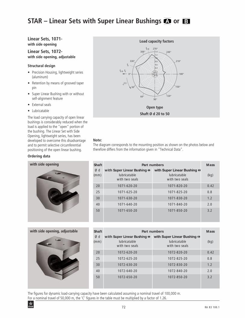
72 RA 83 100.1
Linear Sets, 1071-with side opening
Linear Sets, 1072-with side opening, adjustable
Note:The diagram corresponds to the mounting position as shown on the photos below andtherefore differs from the information given in "Technical Data".
STAR – Linear Sets with Super Linear Bushings or
Structural design
• Precision Housing, lightweight series(aluminum)
• Retention by means of grooved taperpin
• Super Linear Bushing with or withoutself-alignment feature
• External seals
• Lubricatable
The load carrying capacity of open linearbushings is considerably reduced when theload is applied to the "open" portion ofthe bushing. The Linear Set with SideOpening, lightweight series, has beendeveloped to overcome this disadvantageand to permit selective circumferentialpositioning of the open linear bushing.
Load capacity factors
26 B 2r
26 B 1r
3 N 67
Open type
Shaft Ø d 20 to 50
f ο f
0°
30°
300°270°
240°
210°
180°
150°
120°90°
60°
330°
f ο
f
1.2
1.0
0.8
0.6
1.4
0.4
(°)
Ordering data
Shaft Part numbers Mass
Ø d with Super Linear Bushing with Super Linear Bushing (mm) lubricatable lubricatable (kg)
with two seals with two seals
20 1071-620-20 1071-820-20 0.42
25 1071-625-20 1071-825-20 0.8
30 1071-630-20 1071-830-20 1.2
40 1071-640-20 1071-840-20 2.0
50 1071-650-20 1071-850-20 3.2
Shaft Part numbers Mass
Ø d with Super Linear Bushing with Super Linear Bushing (mm) lubricatable lubricatable (kg)
with two seals with two seals
20 1072-620-20 1072-820-20 0.42
25 1072-625-20 1072-825-20 0.8
30 1072-630-20 1072-830-20 1.2
40 1072-640-20 1072-840-20 2.0
50 1072-650-20 1072-850-20 3.2
with side opening
with side opening, adjustable
The figures for dynamic load-carrying capacity have been calculated assuming a nominal travel of 100,000 m.For a nominal travel of 50,000 m, the 'C' figures in the table must be multiplied by a factor of 1.26.
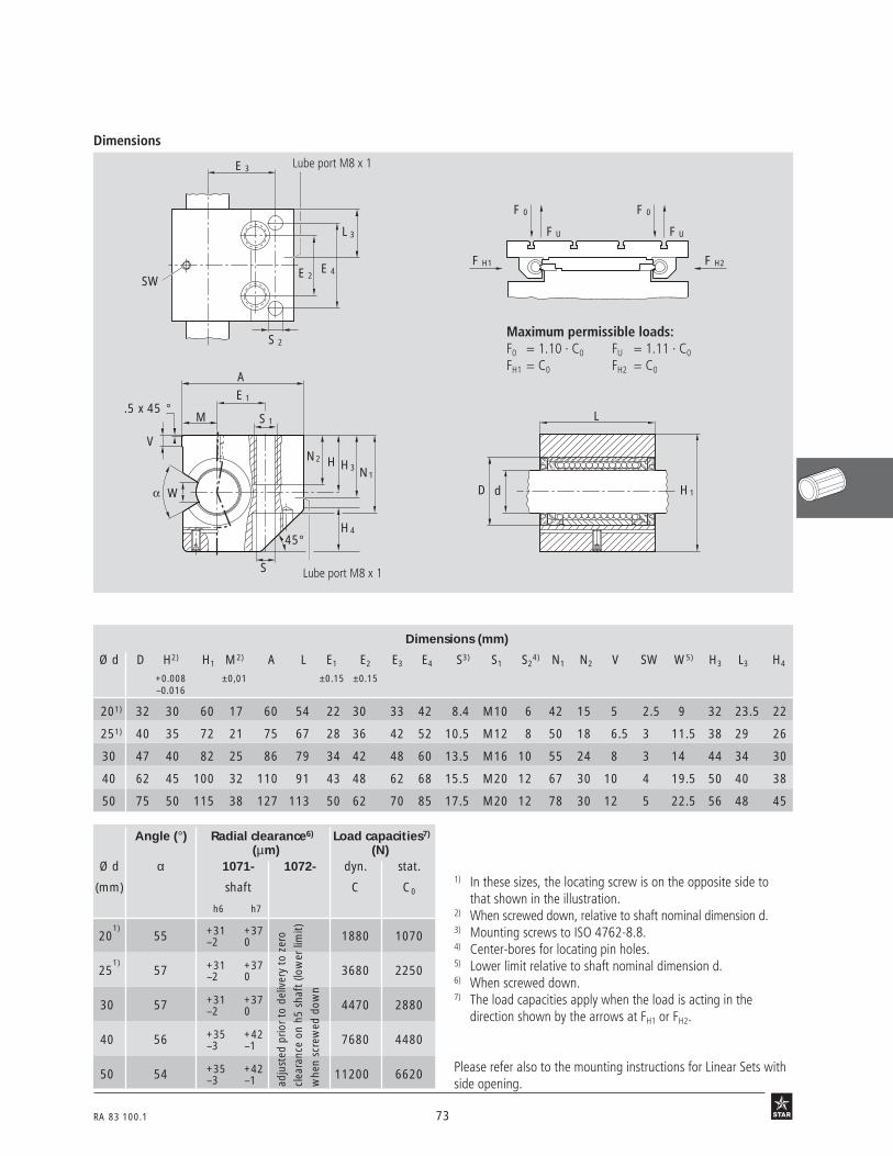
RA 83 100.1 73
Dimensions
Angle (°) Radial clearance6) Load capacities7)
(µm) (N)Ø d α 1071- 1072- dyn. stat.
(mm) shaft C C0
h6 h7
201)
55 +31 +37 1880 1070–2 0
251)
57 +31 +37 3680 2250–2 0
30 57 +31 +37 4470 2880–2 0
40 56 +35 +42 7680 4480–3 –1
50 54 +35 +42 11200 6620–3 –1
Dimensions (mm)
Ø d D H2) H1 M2) A L E1 E2 E3 E4 S3) S1 S24) N1 N2 V SW W5) H3 L3 H4
+0.008 ±0,01 ±0.15 ±0.15–0.016
201) 32 30 60 17 60 54 22 30 33 42 8.4 M10 6 42 15 5 2.5 9 32 23.5 22
251) 40 35 72 21 75 67 28 36 42 52 10.5 M12 8 50 18 6.5 3 11.5 38 29 26
30 47 40 82 25 86 79 34 42 48 60 13.5 M16 10 55 24 8 3 14 44 34 30
40 62 45 100 32 110 91 43 48 62 68 15.5 M20 12 67 30 10 4 19.5 50 40 38
50 75 50 115 38 127 113 50 62 70 85 17.5 M20 12 78 30 12 5 22.5 56 48 45
L 3
E 3
E 4E 2
S 2
SW
A
W
V
.5 x 45 °S 1M
E 1
S
N2 H H3 N1
H445 °
dD
L
H1
F 0
F U
F 0
F U
F H2F H1
adju
sted
prio
r to
del
iver
y to
zer
o
clea
ranc
e on
h5
shaf
t (lo
wer
lim
it)
whe
n sc
rew
ed d
own
1) In these sizes, the locating screw is on the opposite side tothat shown in the illustration.
2) When screwed down, relative to shaft nominal dimension d.3) Mounting screws to ISO 4762-8.8.4) Center-bores for locating pin holes.5) Lower limit relative to shaft nominal dimension d.6) When screwed down.7) The load capacities apply when the load is acting in the
direction shown by the arrows at FH1 or FH2.
Please refer also to the mounting instructions for Linear Sets withside opening.
27 b3 27 b4
Maximum permissible loads:F0 = 1.10 · C0 FU = 1.11 · C0
FH1 = C0 FH2 = C0
Lube port M8 x 1
Lube port M8 x 1

74 RA 83 100.1
Linear Sets, 1085-closed type
Linear Sets, 1032-adjustable
Ordering data
Shaft Part numbers MassØ d
(mm) (kg)
12 1085-612-20 0.27
16 1085-616-20 0.41
20 1085-620-20 0.72
25 1085-625-20 1.35
30 1085-630-20 2.01
40 1085-640-20 3.67
50 1085-650-20 6.30
Shaft Part numbers MassØ d
(mm) (kg)
10 1032-610-20 0.20
12 1032-612-20 0.27
16 1032-616-20 0.41
20 1032-620-20 0.72
25 1032-625-20 1.35
30 1032-630-20 2.01
40 1032-640-20 3.67
50 1032-650-20 6.30
STAR – Linear Sets with Super Linear Bushings Tandem version
Structural design
• Precision Tandem Linear Set, light-weight series (aluminum)
• Two Super Linear Bushings
• External seals
• Fully sealed
• Fitting edge(for adjustable Tandem version)
• Lubricatable
closed type
adjustable
32 B 1r
32 B 2r
The figures for dynamic load-carrying capacity have been calculated assuming a nominal travel of 100,000 m.For a nominal travel of 50,000 m, the 'C' figures in the table must be multiplied by a factor of 1.26.

RA 83 100.1 75
Dimensions
Radial clearance (µm) Load capacities4) (N)
Ø d 1085- 1032- dyn. stat.
(mm) shaft C C0h6 h7
10 – – 890 660– –
12 +38 +43 1250 840+10 +12
16 +38 +43 1530 1060+10 +12
20 +43 +49 3020 2100+11 +13
25 +43 +49 5910 4360+11 +13
30 +43 +49 7180 5580+11 +13
40 +50 +57 12300 8700+12 +14
50 +50 +57 18000 12940+12 +14
Dimensions (mm)
Ø d D H1) H1 H3 M1) B B1 L E1 E2 E3 E4 E5 E6 S2) S1 S22) S3 S4
3) N N1 N2 N3 V SW H4+0.008 ±0.01–0.016
10 19 16 31.5 9 20 – 40 70 – – 52 29 20 31 – – 4.3 M5 4 – – 15 11 5 2.5 10
12 22 18 35 10 21.5 42 43 76 40 30 56 32 24 34 5.3 M6 4.3 M5 4 13 28 16.5 11 5 2.5 10
16 26 22 42 12 26.5 50 53 84 45 36 64 40 28 42 5.3 M6 5.3 M6 4 13 35 21 13 5 3 13
20 32 25 50 13 30 60 60 104 55 45 76 45 32 50 6.4 M8 6.6 M8 5 18 41 24 18 5 4 16
25 40 30 60 15 39 74 78 130 70 54 94 60 42 64 8.4 M10 8.4 M10 6 22 49 29 22 6.5 5 20
30 47 35 70 16 43.5 84 87 152 85 62 106 68 52 72 10.5 M12 8.4 M10 6 26 56 34 22 8 5 22
40 62 45 90 20 54 108 108 176 100 80 124 86 60 90 13.5 M16 10.5 M12 8 34 74 44 26 10 6 28
50 75 50 105 20 66 130 132 224 125 100 160 108 80 108 13.5 M16 13.5 M16 10 34 89 49 35 12 8 37
adju
sted
prio
r to
del
iver
y to
zer
ocl
eara
nce
on h
5 sh
aft
(low
er li
mit)
whe
n sc
rew
ed d
own
Adjustable
Closed type
1) When screwed down, relative to shaft nominal dimension d.2) Mounting screws to ISO 4762-8.8.3) Center-bores for locating pin holes.4) Load capacity when both Linear Bushings are equally loaded.
The load capacities stated are minimum values as the positionand direction of load cannot always be precisely defined.
BM
N 3
S 3
1
VN 2
S 2 S 4SW
M8x1H3 H
H 4 45 °
B
S
H 3
M8x1
HNN1
S1
Closed type
d
L
D1H
Adjustable
4E
3E
5E
6E
2E
1E
32 B 3
32 B 5
32 B 4
Note on lubrication for Linear Sets 1085:Lubricate only when shaft inserted; add lubricant until excessemerges at the vent hole.
Lube port M8 x 1
Lube port M8 x 1
Vent hole

76 RA 83 100.1
Linear Sets, 1087-open type
Linear Sets, 1034-open type, adjustable
open type
Ordering data
open type, adjustable Shaft Part numbers Mass
Ø d
(mm) (kg)
12 1034-612-20 0.22
16 1034-616-20 0.34
20 1034-620-20 0.62
25 1034-625-20 1.17
30 1034-630-20 1.68
40 1034-640-20 3.15
50 1034-650-20 5.50
STAR – Linear Sets with Super Linear Bushings Tandem version
Structural design
• Precision Tandem Linear Set,lightweight series (aluminum)
• Two Super Linear Bushings
• Two external seals
• Fitting edge(for adjustable Tandem version)
• Lubricatable
33 B 1r
33 B 2r
The figures for dynamic load-carrying capacity have been calculated assuming a nominal travel of 100,000 m.For a nominal travel of 50,000 m, the 'C' figures in the table must be multiplied by a factor of 1.26.
Shaft Part numbers Mass
Ø d
(mm) (kg)
12 1087-612-20 0.22
16 1087-616-20 0.34
20 1087-620-20 0.62
25 1087-625-20 1.17
30 1087-630-20 1.68
40 1087-640-20 3.15
50 1087-650-20 5.50

RA 83 100.1 77
Dimensions
Angle (°) Radial clearance7) Load capacities8)
(µm) (N)Ø d α 1087- 1034- dyn. stat.
(mm) shaft C C0h6 h7
12 66 +28 +33 1430 1020–1 +1
16 68 +28 +33 1720 1260–1 +1
20 55 +31 +37 3050 2140–2 0
25 57 +31 +37 5980 4500–2 0
30 57 +31 +37 7260 5760–2 0
40 56 +35 +42 12500 8960–3 –1
50 54 +35 +42 18200 13240–3 –1
adju
sted
prio
r to
del
iver
y to
zer
ocl
eara
nce
on h
5 sh
aft
(low
er li
mit)
whe
n sc
rew
ed d
own
1) In the open, adjustable version, H2 = 28 mm.2) When screwed down, relative to shaft nominal dimension d.3) Mounting screws to DIN 6912-8.8.4) Mounting screws to ISO 4762-8.8.5) Center-bores for locating pin holes.6) Lower limit relative to shaft nominal dimension d.7) When screwed down.8) Load capacity when both Linear Bushings are equally loaded.
The load capacities apply when the load is actingalong the line = 0°.
4E
3E
5E
6E
2E
1E
Open type,adjustable
Open type
Open type, adjustableOpen type
d
L
D2H
33 B 5
33 B 3 33 B 4
BM
N3
S3
1
VN2
S4
SWM8x1
H3 H
S2
WH4
45 °
B
S
H
M8x1
HNN
S
Wα
1
13
Lube port M8 x 1
Lube port M8 x 1
Dimensions (mm)
Ø d D H2) H2 H3 M2) B B1 L E1 E2 E3 E4 E5 E6 S3) S1 S24) S3 S4
5) N N1 N2 N3 V SW W6) H4
+0.008 ±0.01–0.016
12 22 18 301) 10 21.5 42 43 76 40 30 56 32 24 34 5.3 M6 4.3 M5 4 13 25 16.5 11 5 2.5 6.5 1.5
16 26 22 35 12 26.5 50 53 84 45 36 64 40 28 42 5.3 M6 5.3 M6 4 13 29.5 21 13 5 2.5 9 2.5
20 32 25 42 13 30 60 60 104 55 45 76 45 32 50 6.4 M8 6.6 M8 5 18 35.5 24 18 5 2.5 9 3.5
25 40 30 51 15 39 74 78 130 70 54 94 60 42 64 8.4 M10 8.4 M10 6 22 43 29 22 6.5 3 11.5 4
30 47 35 60 16 43.5 84 87 152 85 62 106 68 52 72 10.5 M12 8.4 M10 6 26 50.5 34 22 8 3 14 6
40 62 45 77 20 54 108 108 176 100 80 124 86 60 90 13.5 M16 10.5 M12 8 34 66 44 26 10 4 19.5 6
50 75 50 88 10 66 130 132 224 125 100 160 108 80 108 13.5 M16 13.5 M16 10 34 77 49 35 12 5 22.5 6

78 RA 83 100.1
Linear Sets, 1083-
Ordering data
Shaft Part numbers Mass
Ø d
(mm) (kg)
12 1083-612-20 0.20
16 1083-616-20 0.32
20 1083-620-20 0.55
25 1083-625-20 1.00
30 1083-630-20 1.50
STAR – Linear Sets with Super Linear Bushings Tandem Flanged version
Structural design
• Precision Flanged Housing,lightweight series (aluminum)
• Two Super Linear Bushings
• Two external seals
• Centering collar
• Fully sealed
• Tapped through holes forscrew-mounting from the base
• Lubricatable
• Radial clearance not adjustable
33 B 2r
The figures for dynamic load-carrying capacity have been calculated assuming a nominal travel of 100,000 m.For a nominal travel of 50,000 m, the 'C' figures in the table must be multiplied by a factor of 1.26.

RA 83 100.1 79
Dimensions
Center fitvia collar D2
Mounting methods:via through-hole S via tapped hole S1 via through-hole S
Dimensions (mm)
Ø d D D21) D3 H H3 B L L1 E1 E2 S2) S1 N1 N2 V
–0.1 ±0.15 ±0.15g7 –0.3
12 22 30 30 34 19 42 76 46 32 24 5.3 M6 13 36 10
16 26 35 35 40 22 50 84 50 38 28 6.6 M8 18 40 10
20 32 42 42 50 27 60 104 60 45 35 8.4 M10 22 50 10
25 40 52 52 60 32 74 130 73 56 42 10.5 M12 26 63 10
30 47 61 61 70 37 84 152 82 64 50 13.5 M16 34 74 10
Radial clearance (µm) Load capacities3) (N)
Ø d dyn. stat.
(mm) shaft C C0h6 h7
12 +38 +43 1250 840+10 +12
16 +38 +43 1530 1060+10 +12
20 +43 +49 3020 2100+11 +13
25 +43 +49 5910 4360+11 +13
30 +43 +49 7180 5580+11 +13
d
L
D2E H
1EB
3H
M8x1
2N
3D
2DV S
1N
1L
1S
1) Recommended mounting bore fit: D2H7
2) Mounting screws to ISO 4762-8.8.3) Load capacity when both Linear Bushings are equally loaded.
The load capacities stated are minimum values as the positionand direction of load cannot always be precisely defined.
36 B 2
36 B 3
36 b 4 36 b 5 36 B 6
Note on lubrication:Lubricate only when shaft inserted; add lubricant until excessemerges at the vent hole.
Vent hole M8 x 1
Vent hole

80 RA 83 100.1
Linear Sets, 1065-closed type
Linear Sets, 1066-adjustable
STAR – Linear Sets with Super Linear Bushings or
Structural design
• Precision Housing(lamellar graphite cast iron)
• Super Linear Bushing with or withoutself-alignment feature
• Internal seals
Ordering data
closed type
adjustable
2 N 2r
38 o 1r
The figures for dynamic load-carrying capacity have been calculated assuming a nominal travel of 100,000 m.For a nominal travel of 50,000 m, the 'C' figures in the table must be multiplied by a factor of 1.26.
Shaft Part numbers Mass
Ø d with Super Linear Bushing with Super Linear Bushing
(mm) with with (kg)internal seals internal seals
12 1066-612-40 1066-812-40 0.15
16 1066-616-40 1066-816-40 0.24
20 1066-620-40 1066-820-40 0.41
25 1066-625-40 1066-825-40 0.79
30 1066-630-40 1066-830-40 1.19
40 1066-640-40 1066-840-40 2.26
50 1066-650-40 1066-850-40 3.15
Shaft Part numbers Mass
Ø d with Super Linear Bushing with Super Linear Bushing
(mm) with with (kg)internal seals internal seals
12 1065-612-40 1065-812-40 0.15
16 1065-616-40 1065-816-40 0.24
20 1065-620-40 1065-820-40 0.42
25 1065-625-40 1065-825-40 0.83
30 1065-630-40 1065-830-40 1.22
40 1065-640-40 1065-840-40 2.29
50 1065-650-40 1065-850-40 3.23

RA 83 100.1 81
Dimensions
Dimensions (mm)
Ø d D H H11) L A1) A1
1) B1) B1 E1 E2 S V1) SW
12 22 18 35 32 42 21 32 20 32±0.15 23±0.15 4.5 5.5 2.5
16 26 22 42 36 50 26 35 22 40±0.15 26±0.15 4.5 6.5 3
20 32 25 50 45 60 28 42 28 45±0.15 32±0.15 4.5 8 3
25 40 30 60 58 74 38 54 40 60±0.15 40±0.15 5.5 9 5
30 47 35 70 68 84 41 60 48 68±0.20 45±0.20 6.6 10 5
40 62 45 90 80 108 51 78 56 86±0.20 58±0.20 9 12 6
50 75 50 105 100 130 57 70 72 108±0.20 50±0.20 9 14 8
Radial clearance Tolerance for H2) Load(µm) (µm) capacities3) (N)
Ø d 1065- 1066- dyn. stat.(mm) shaft 1065- C C0
h6 h7 1066-
12 +38 +43 +8 770 420+10 +12 –16
16 +38 +43 +8 940 530+10 +12 –16
20 +43 +49 +8 1860 1050+11 +13 –16
25 +43 +49 +8 3640 2180+11 +13 –16
30 +43 +49 +8 4420 2790+11 +13 –16
40 +50 +57 +8 7590 4350+12 +14 –16
50 +50 +57 +13 11100 6470+12 +14 –21
1) Tolerance to DIN 1686-GTB 15.2) When screwed down, relative to shaft nominal dimension d.3) The load capacities stated are minimum values as the position
and direction of load cannot always be precisely defined.
E 2
B
S
V
H
E 1
A
A1
45 °
B 1
L
d D H 1
SW
38 o 4
adju
sted
prio
r to
deliv
ery
to z
ero
clear
ance
on h
5 sh
aft (
low
er li
mit)
whe
n sc
rew
ed d
own

82 RA 83 100.1
Linear Sets, 1067-open type
Linear Sets, 1068-open type, adjustable
Shaft Part numbers Mass
Ø d with Super Linear Bushing with Super Linear Bushing
(mm) with with (kg)internal seals internal seals
12 1067-612-40 1067-812-40 0.13
16 1067-616-40 1067-816-40 0.20
20 1067-620-40 1067-820-40 0.36
25 1067-625-40 1067-825-40 0.70
30 1067-630-40 1067-830-40 1.05
40 1067-640-40 1067-840-40 2.05
50 1067-650-40 1067-850-40 2.77
Shaft Part numbers Mass
Ø d with Super Linear Bushing with Super Linear Bushing
(mm) with with (kg)internal seals internal seals
12 1068-612-40 1068-812-40 0.12
16 1068-616-40 1068-816-40 0.20
20 1068-620-40 1068-820-40 0.36
25 1068-625-40 1068-825-40 0.69
30 1068-630-40 1068-830-40 1.02
40 1068-640-40 1068-840-40 2.02
50 1068-650-40 1068-850-40 2.71
STAR – Linear Sets with Super Linear Bushings or
Structural design
• Precision Housing(spheroidal graphite cast iron)
• Retention by means of locating screw
• Super Linear Bushings with or withoutself-alignment feature
• Internal seals
open type, adjustable
Ordering data
open type
Load capacity factors
Open typeShaft Ø d 12 and 16 Shaft Ø d 20 to 50
3404
3 N 69
12 B 1 12 B 2
f οf(°)
0°30°
300°
270°
240°
210°180°
150°
120°
90°
60°
330°
f ο
f 1.2
1.0
0.8
0.6
1.4
0.4
0°30° 330°
270°
240°
210°180°
150°
120°
90°
60° 300°
0.4
1.2
1.0
0.8
0.6
1.4
f(°)
f
f ο
f ο
The figures for dynamic load-carrying capacity have been calculated assuming a nominal travel of 100,000 m.For a nominal travel of 50,000 m, the 'C' figures in the table must be multiplied by a factor of 1.26.

RA 83 100.1 83
Dimensions
S
V
H
W
α
E 1
A
B 1
E 2
B
L
d D H 2
SW
Angle (°) Radial clearance (µm) Tolerance Loadα (µm) capacities5) (N)
Ø d 1067- 1068- for dimension H4) dyn. stat.shaft 1067 C C0
h6 h7 1068
12 66 +28 +33 +8 880 510–1 +1 –16
16 68 +28 +33 +8 1060 630–1 +1 –16
20 55 +31 +37 +8 1880 1070–2 0 –16
25 57 +31 +37 +8 3680 2250–2 0 –16
30 57 +31 +37 +8 4470 2880–2 0 –16
40 56 +35 +42 +8 7680 4480–3 –1 –16
50 54 +35 +42 +13 11200 6620–3 –1 –21
Dimensions (mm)
Ø d D H H22) L A2) B2) B1 E1 E2 S V2) W3) SW
121) 22 18 28 32 42 32 20 32±0.15 23±0.15 4.5 5.5 6.5 2.5
161) 26 22 35 36 50 35 22 40±0.15 26±0.15 4.5 6.5 9 2.5
201) 32 25 42 45 60 42 28 45±0.15 32±0.15 4.5 8 9 2.5
251) 40 30 51 58 74 54 40 60±0.15 40±0.15 5.5 9 11.5 3
30 47 35 60 68 84 60 48 68±0.20 45±0.20 6.6 10 14 3
40 62 45 77 80 108 78 56 86±0.20 58±0.20 9 12 19.5 4
50 75 50 88 100 130 70 72 108±0.20 50±0.20 9 14 22.5 5
1) In these sizes, the locating screw is onthe opposite side to that shown in theillustration.
2) Tolerance to DIN 1686-GTB 15.3) Lower limit relative to shaft nominal
dimension d.4) When screwed down, relative to shaft
nominal dimension d.5) The load capacities apply when the
load is acting along the line = 0°.
3 N 61
adju
sted
prio
r to
del
iver
y to
zer
ocl
eara
nce
on h
5 sh
aft
(low
er li
mit)
whe
n sc
rew
ed d
own

84 RA 83 100.1
Linear Sets, 1073-with side opening
Linear Sets, 1074-with side opening, adjustable
Shaft Part numbers Mass
Ø d with Super Linear Bushing with Super Linear Bushing
(mm) with two with two (kg)seals seals
20 1073-620-00 1073-820-00 1.0
25 1073-625-00 1073-825-00 1.9
30 1073-630-00 1073-830-00 2.8
40 1073-640-00 1073-840-00 4.8
50 1073-650-00 1073-850-00 8.0
Shaft Part numbers Mass
Ø d with Super Linear Bushing with Super Linear Bushing
(mm) with two with two (kg)seals seals
20 1074-620-00 1074-820-00 1.0
25 1074-625-00 1074-825-00 1.9
30 1074-630-00 1074-830-00 2.8
40 1074-640-00 1074-840-00 4.8
50 1074-650-00 1074-850-00 8.0
Note:The diagram corresponds to the mounting position as shown on the photos below andtherefore differs from the information given in "Technical Data".
STAR – Linear Sets with Super Linear Bushings or
Structural design
• Precision Housing(spheroidal graphite cast iron)
• Retention by means of groovedtaper pin
• Super Linear Bushing with or withoutself-alignment feature
• External seals
The load carrying capacity of open linearbushings is considerably reduced when theload is applied to the "open" portion ofthe bushing. The Linear Set with SideOpening has been developed to overcomethis disadvantage and to permit selectivecircumferential positioning of the openlinear bushing.
Ordering data
with side opening
with side opening, adjustable
Load capacity factors
2 N 4r
42 o 1r
3 N 65
0°
30°
300°270°
240°
210°
180°
150°
120°90°
60°
330°
f ο
f
1.2
1.0
0.8
0.6
1.4
0.4
(°)
f ο f
Open type
Shaft Ø d 20 to 50
The figures for dynamic load-carrying capacity have been calculated assuming a nominal travel of 100,000 m.For a nominal travel of 50,000 m, the 'C' figures in the table must be multiplied by a factor of 1.26.

RA 83 100.1 85
Dimensions
Maximum permissible loads:
F0 = 1.10 · C0 FU = 1.11 · C0
FH1 = C0 FH2 = C0
Ø d Angle (°) Tolerance Radial clearance (µm)6) Load for H5) capacities7) (N)
(mm) α (µm) 1073- 1074- dyn. stat.shaft
h6 h7 C C0
201) 55 +8 +31 +37 1880 1070–16 –2 0
251) 57 +8 +31 +37 3680 2250–16 –2 0
30 57 +8 +31 +37 4470 2880–16 –2 0
40 56 +8 +35 +42 7680 4480–16 –3 –1
50 54 +13 +35 +42 11200 6620–21 –3 –1
Dimensions (mm)
Ø d H H12) L2) A2) E1 E2 N D V S SW O3) R2) W4)
201) 30 60 60 60 22±0.25 30±0.25 17 32 42 9 2.5 M8x60 37 9
251) 35 72 73 75 28±0.25 36±0.25 21 40 50 11 3 M10x70 45 11.5
30 40 82 85 86 34±0.5 42±0.5 25 47 55 13.5 3 M12x80 51 14
40 45 100 97 110 43±0.5 48±0.5 32 62 67 15.5 4 M14x90 66 19.5
50 50 115 125 127 50±0.5 62±0.5 38 75 78 17.5 5 M16x110 77 22.5
Dd
L E2
S
A
H
SW
W
VH1
E 1 N
O
R
adju
sted
prio
r to
del
iver
yto
zer
o cl
eara
nce
on h
5sh
aft
(low
er li
mit)
whe
nsc
rew
ed d
own
1) In these sizes, the locating screw is onthe opposite side to that shown in theillustration.
2) Tolerance to DIN 1685-GTB 15.3) Hex. socket head cap screws to
ISO 4762-8.8.4) Lower limit relative to shaft nominal
dimension d.5) Relative to shaft nominal dimension d.6) When screwed down.7) The load capacities apply when the
load is acting along the line shown bythe arrows at FH1 or FH2.
42 o2 26 B 3
D
F
FU FU
F
FF
O O
H2H1

86 RA 83 100.1
Shaft Part numbers Mass
Ø d with Super Linear Bushing with Super Linear Bushing
(mm) with two with two (kg)seals seals
12 1081-612-40 1081-812-40 0.095
16 1081-616-40 1081-816-40 0.16
20 1081-620-40 1081-820-40 0.30
25 1081-625-40 1081-825-40 0.57
30 1081-630-40 1081-830-40 0.85
40 1081-640-40 1081-840-40 1.65
50 1081-650-40 1081-850-40 3.40
Linear Sets, 1081-Flanged type
Structural design
• Precision Flanged Housing (lamellargraphite cast iron)
• Two retaining rings, plus two spacerrings (steel) for sizes 12 to 40
• Super Linear Bushings with or withoutself-alignment feature
• Internal seals
• The radial clearance is not adjustable
STAR – Linear Sets with Super Linear Bushings or
Ordering data
43 o 1r
The figures for dynamic load-carrying capacity have been calculated assuming a nominal travel of 100,000 m.For a nominal travel of 50,000 m, the 'C' figures in the table must be multiplied by a factor of 1.26.

RA 83 100.1 87
Dimensions
Dimensions (mm)
Ø d B1) L L1 D D1 D21) E S V1) W
+1 H13
12 42 32 12 22 24 28 30±0.12 5.5 6 10
16 50 36 15 26 28.5 34 35±0.12 5.5 8 10.5
20 60 45 18 32 35 42 42±0.15 6.6 10 13.5
25 74 58 23 40 43 54 54±0.15 6.6 12 17.5
30 84 68 26 47 49.5 62 60±0.25 9.0 14 21
40 108 80 36 62 66.5 80 78±0.25 11 16 22
50 130 100 72 75 81 98 98±0.25 11 18 14
Radial clearance (µm) Load capacities2) (N)
Ø d dyn. stat.
(mm) shaft C C0h6 h7
12 +38 +43 770 420+10 +12
16 +38 +43 940 530+10 +12
20 +43 +49 1860 1050+11 +13
25 +43 +49 3640 2180+11 +13
30 +43 +49 4420 2790+11 +13
40 +50 +57 7590 4350+12 +14
50 +50 +57 11100 6470+12 +14
1) Tolerance to DIN 1686-GTB 15.2) The load capacities stated are minimum values as the position
and direction of load cannot always be precisely defined.
43 o 3b43 02
E
B
E
S
B D2dD1
L 1
W V
L
D

88 RE 83 100/09.99
Super Linear Bushings and consist of:• a one-piece polyacetal ball retainer
• hardened steel segmental load bearing plates with ground balltracks and ground outer surfaces
• balls of antifriction bearing steel quality
• metal holding rings as sturdy end caps
• replaceable twin-lip seal rings (in the sealed version)
• seal strips (in the fully sealed, open type)
STAR – Super Linear Bushings and
Super Linear Bushings and have even more load bearing plates and ballrows than the highly successful conventional version.This means more than double the dynamic load-carrying capacity – at no costto the self-alignment feature.
Super Linear Bushings and for extremely high loads.
17 B 1
Design variants• Closed or open types
• With or without seal rings
• With or without seal strip
• Optional screw-mounted Linear Sets (Linear Bushing with Housing)in different types
• Super Linear Bushings and are also available with STAR-Resist corro-sion protection (yellow chromatized zinc-iron coating) and a special version(black chromatized)
The advantages• High load-carrying capacity and service life
• High running speed
• Automatic compensation of alignment errors or shaft deflection
• Smooth and stutter-free running of the balls in the ball tracks
• High rigidity
• Fully sealed by seal rings and seal strips
• Good contact between steel load bearings plates and the innersurface of the mounting hole
• In-service lubrication via lubrication hole or pockets
• Greater efficiency due to retention by locating screw

RE 83 100/09.99 89
Open type
• Uniform load distribution over the open sectionthanks to symmetrically arranged ball tracks
• Fully sealed
• Screw-mounted metal end caps
123 B 1

90 RE 83 100/09.99
STAR – Super Linear Bushings and Technical Data
Dimensions/Interchangeability Super Linear Bushings and have the same outside dimensions as Super LinearBushings and as well as Standard Linear Bushings (caution: different retention,radial clearance, load capacity and lubrication). For this reason, all the versions areinterchangeable.
Sealing Two-fold protection through dual-action seals:
• the outer lip prevents the penetration of dirt and foreign bodies
• the inner lip prevents excessive loss of lubricant
In closed types, the seals are flexibly mounted, floating into good contact underall service conditions. The open types also have a seal strip to fully seal the gap betweenthe ball retainer and the shaft. All seals can be replaced if necessary.
Please observe the general technical principles and mounting instructions at the beginning of this catalog aswell as the additional technical data given below.
Very low friction due to the rolling friction principle. Extremely low breakaway forces. Thefriction µ of unsealed Super Linear Bushings using oil as a lubricant lies between 0.001and 0.004.The friction is lowest under high load. It may, however, be greater than the stated valuewhen only a slight load is applied.For Super Linear Bushings fitted at both ends with internal wiper seals and not subject toradial loading, the frictional drag (see table below) depends on the speed and the type oflubrication.
Friction
Velocity vmax = 5 m/s
Acceleration amax = 150 m/s2
Operating temperature up to 100 °C
Shaft Closed and open type Open type Super linear bushingsSuper Linear Bushings and and fully sealed
with internal wiper sealsØ d Breakaway force Frictional drag Breakaway force Frictional drag
(mm) (N) approx. (N) approx. (N) approx. (N) approx.
20 5 2.5 7.5 4
25 7 3 10.5 4.5
30 9 4 13.5 6
40 12 5 18 7.5
50 15 6 22.5 9
60 18 7 27 10.5

RE 83 100/09.99 91
Closed type Open typeDirection of load and its influence onthe load-carrying capacity
=0°
270°90°
180°
Main directions of load
Load capacity factors
The load capacities C and C0 apply whenthe load is acting along the line = 0°.If the load is acting in any other direction,these load capacities must be multiplied bythe factors f (dynamic load capacity C) orf 0 (static load capacity C0).
12 09 B 3 12 09 B 4 12 09 B 5 1209 B 6
12 09 B 212 09 B 1
Hauptlast
Load capacity factor f
Shaft Super Linear Bushing Super Linear Bushing
Ø d
20-25 1 0.80 0.98 1 0.80 0.67 1 0.79 1 1 0.79 0.52
30-60 1 0.70 0.91 1 0.70 0.62 1 0.86 1 1 0.86 0.59
Load capacity factor f 0
20-25 1 0.70 0.87 1 0.70 0.67 1 0.68 1 1 0.68 0.50
30-60 1 0.62 0.80 1 0.62 0.61 1 0.83 1 1 0.83 0.55

92 RE 83 100/09.99
STAR – Super Linear Bushings and Technical Data
12 10 B1 12 10 B2
12 10 B4
Open type
Open typeClosed type
Closed type
Super Linear Bushings can be installed inany mounting position.The mounting position should be chosenso that the load acts mainly along the line
= 0°.
Load capacity factors
Shaft diameter d 30-60
12 10 B3
Super Linear Bushing
Shaft diameter d 20-25
0°30° 330°
300°
270°
240°
210°180°
150°
120°
90°
60°
0.90.80.70.60.5
f(°)
f
f ο
f ο
30° 330°
300°
270°
240°
210°180°
150°
120°
90°
60°
0.90.80.70.60.5
f
0°
f
(°)f ο
f ο
0°30° 330°
300°
270°
240°
210°180°
150°
120°
90°
60°
0.90.80.70.60.5
(°)
f οf
f ο
f
0°30° 330°
300°
270°
240°
210°180°
150°
120°
90°
60°
0.90.80.70.60.5
(°)
f οf
f ο
f

RE 83 100/09.99 93
12 10 B5 12 10 B6
Open type
Open type
Closed type
Closed type
0°30° 330°
300°
270°
240°
210°180°
150°
120°
90°
60°
(°)f
f0.90.80.70.60.5
f ο
f ο
0°30° 330°
300°
270°
240°
210°180°
150°
120°
90°
60°
f(°)
f0.90.80.70.60.5
f ο
f ο
(°) f0°
30° 330°
300°
270°
240°
210°180°
150°
120°
90°
60°
0.90.80.70.60.5
f
f ο
f ο
0°30° 330°
300°
270°
240°
210°180°
150°
120°
90°
60°
0.90.80.70.60.5
f(°)
f
f ο
f ο
Super Linear Bushings can be installed inany mounting position.The mounting position should be chosenso that the load acts mainly along the line
= 0°.
12 10 B512 10 B6
An indentation in the plastic ball retainerof closed Super Linear Bushing (seemagnification) indicates the main directionof load = 0° (maximum load capacity).
Super Linear Bushing
Shaft diameter d 20-25
Shaft diameter d 30-50

94 RE 83 100/09.99
STAR – Super Linear Bushings and Technical Data
In short-stroke applications, the service life of the shafts is shorter than that of the SuperLinear Bushings. For this reason, the load capacities C given in the tables must bemultiplied by the factor fW.
Reduced load capacity athigh loads
Reduced load capacity inshort-stroke applications
Reduced load capacity at high loads F. The dynamic load capacity must be multiplied bythe load factor fF.
12 11 B2
12 11 B1
Stroke (mm)
25 30 40 50 6020
1.0
0.50.60.70.80.9
fW
0 20 40 60 80 100 120 140 160 180 200 220 240 260 280 300 320 340 360
FCo
1.0
0.2
0.4
0.6
0.8fF
0.1 0.2 0.90.3 0.4 0.5 0.6 0.7 0.8 10

RE 83 100/09.99 95
Self-alignment Super Linear Bushings automatically compensate for alignment errors of up to 30'. Noreduction in load-carrying capacity due to pressure between bushing edge and shaft.
Running speed and High acceleration and running speed due to:characteristics • hard-wearing ball retainer
Smooth and stutter-free running of the balls in the ball tracks due to:
• optimized track geometry at both ends
• ground ball tracks
Ground outer surfaces The ground outer surface of the load bearing plates produces very good contact betweenthe steel bearing plates and the inner surface of the mounting hole.
Load-carrying capacity The high number of ball tracks provides a very high load-carrying capacity andlong service life.and service life
Lubrication In-service lubrication is possible via the lube hole in closed type or via the greasepockets in the ball retainer in types and .
Retention Super Linear Bushings and feature simple and economical radial and axial retentionby locating screw.

96 RE 83 100/09.99
STAR – Super Linear Bushings and Customer-Built Housings
RetentionSuper Linear Bushing
Retention by means of locating screwinserted through hole S1.
Important:
Observe position of bearing plates relativeto locating screw hole S1.
S1
LL
D1
L 3
L 4
D2D3D4
L 2
L 1
L
dS1
= =
12 06 B 2
12 06 B 1
Shaft Dimensions (mm) Locating screw
Ø d S1 L L1 L2 L3 L4 D1 D2 D3 D4 TighteningPart numbers torque
(mm) ±0.1 +0.2 min. +0.2 min. +0.1 H13 H13 (Nm)
20 3 27 9 7 2 3.2 3.1 M4 4.5 8 8427-008-09 1.9
25 3.5 33.5 11 8.5 2.3 4 3.6 M5 5.5 10 8427-003-09 3.8
30 3.5 37 11 8.5 2.3 4 3.6 M5 5.5 10 8427-003-09 3.8
40 3.5 44.5 11 8.5 2.3 4 3.6 M5 5.5 10 8427-003-09 3.8
50 4.5 59.5 17 14 3 4.7 4.6 M6 6.6 11 8427-004-09 6.7
60 6 72.5 22 18 4 6 6.2 M8 9 15 8427-007-09 16
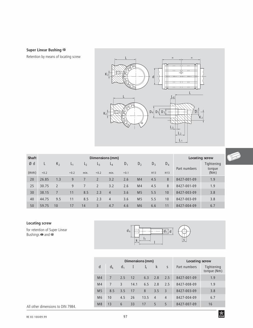
RE 83 100/09.99 97
Locating screw
for retention of Super LinearBushings and
L
D1
L 3
L 4
D3
L 2
L 1
K2
D2D4
L
K2
L
d
= =
K2
Super Linear Bushing
Retention by means of locating screw
12 06 B 4
12 06 B 3
Shaft Dimensions (mm) Locating screw
Ø d L K2 L1 L2 L3 L4 D1 D2 D3 D4 TighteningPart numbers torque
(mm) +0.2 +0.2 min. +0.2 min. +0.1 H13 H13 (Nm)
20 26.85 1.3 9 7 2 3.2 2.6 M4 4.5 8 8427-001-09 1.9
25 30.75 2 9 7 2 3.2 2.6 M4 4.5 8 8427-001-09 1.9
30 38.15 7 11 8.5 2.3 4 3.6 M5 5.5 10 8427-003-09 3.8
40 44.75 9.5 11 8.5 2.3 4 3.6 M5 5.5 10 8427-003-09 3.8
50 59.75 10 17 14 3 4.7 4.6 M6 6.6 11 8427-004-09 6.7
d k
l1k l
d1 d
s12 06 B 5
All other dimensions to DIN 7984.
Dimensions (mm) Locating screw
d dk d1 I I1 k s Part numbers Tighteningtorque (Nm)
M4 7 2.5 12 6.3 2.8 2.5 8427-001-09 1.9
M4 7 3 14.1 6.5 2.8 2.5 8427-008-09 1.9
M5 8.5 3.5 17 8 3.5 3 8427-003-09 3.8
M6 10 4.5 26 13.5 4 4 8427-004-09 6.7
M8 13 6 33 17 5 5 8427-007-09 16

98 RE 83 100/09.99
Lubrication andretention
Super Linear Bushing (closed type)
Lubrication and retention by means ofhollow screw inserted through hole S1.Dimensions given here are for customer-built housings.
Important:
Observe the position of load bearing platesrelative to hole S1.
STAR – Super Linear Bushings and Customer-Built Housings
Dimensions (mm) Hollow screw
d d1 d2 I I1 I2 s Part numbers Tighteningtorque (Nm)
M8x1 3 6.5 10.5 5 3.5 4 8432-010-00 5.5
M8x1 3.5 6.5 14.5 6 5.6 4 8432-007-00 5.5
M8x1 4.5 6.5 18 8 7 4 8432-008-00 5.5
M10x1 6 8.5 25 11.5 10.2 5 8432-009-00 9.5
Linear Dimensions (mm) Hollow screwBushing Tightening
Part Number S1 L D1 D2 A1 A2 A3 F Part numbers torquemin. +0.1 ±0.1 max. min. (Nm)
0732-220-40 3 46 3.1 M8x1 18.5 20.5 31 0.3x45˚ 8432-010-00 5.5
0732-225-40 3.5 59 3.6 M8x1 22.5 25 38 0.3x45˚ 8432-007-00 5.5
0732-230-40 3.5 69 3.6 M8x1 26 28.5 41.5 0.3x45˚ 8432-007-00 5.5
0732-240-40 3.5 81 3.6 M8x1 33.5 36 49 0.3x45˚ 8432-007-00 5.5
0732-250-40 4.5 101 4.6 M8x1 42 44.5 59 0.3x45˚ 8432-008-00 5.5
0732-260-40 6 126 6.2 M10x1 51 53.5 71.5 0.3x45˚ 8432-009-00 9.5
d 2
l
d
s
d 1
l 2l 1
L/2 L/2
L
A 3
D 2
A 3
A 2
A 1
D 1
F
S 1
The lubrication channels shown here have been designed for lubrication with grease. If oilis used instead, check whether all anti-friction bearings are being properly lubricated.
Hollow screw
for lubrication and retention of SuperLinear Bushing (closed type) throughhole S1
1208 B 2
12 08 B 1

RE 83 100/09.99 99
LubricationSuper Linear Bushing (closed type)
Lubrication duct, ring groove and threadedlube port for lubrication with grease.Dimensions given for customer-built housing.
B2
H2H1
M8x1Ø7
min 6 D
A-A
F F
L
L/2
L/2
D1
7 L 1
AA
45°
45°
H1
M8x1Ø7
min 6 D
A-A
L
L/2
L/2
D1
7 L 1
AA
45°
45°
Super Linear Bushings and (open type)
Lubrication duct, ring groove and threadedlube port for lubrication with grease.Dimensions given for customer-built housing.
12 90 B 2
Linear Bushings Dimensions (mm)
Part numbers D L L1 H1 D1 B2 H2 Fmin. +0.5 ±0.2
0733-220-45 0731-220-45 32 46 7 16 34 8 – R13
0733-225-45 0731-225-45 40 59 8.5 20 42 11.9 0.5 R15
0733-230-45 0731-230-45 47 69 8.5 23.5 49 12.8 1 R18
0733-240-45 0731-240-45 62 81 10.5 31 66 19.9 1.1 R23
0733-250-45 0731-250-45 75 101 11.5 37.5 79 22.6 2 R28
0733-260-45 – 90 126 13 45 94 30.8 3 R31.5
12 90 B 1
Linear Dimensions (mm)
Bushing
Part numbers D L L1 H1 D1
min. +0.5 ±0.2
0730-220-40 32 46 7 16 34
0730-225-40 40 59 8.5 20 42
0730-230-40 47 69 8.5 23.5 50
0730-240-40 62 81 10.5 31 66
0730-250-40 75 101 11.5 37.5 79

100 RE 83 100/09.99
Super Linear Bushing, 0732-closed type
Super Linear Bushing, 0733-open type
12 10 B1 12 10 B2
12 13 B1 12 13 B3
STAR – Super Linear Bushings
Structural Design
• POM ball retainer
• Hardened steel segmental load bearingplates with ground ball tracks andground outer surfaces
• Two metal holding rings
• With or without twin-lip seal rings
• With or without axial seal strip.
For precise values for the 4 maindirections of load see "TechnicalData – Load capacity factors".
Shaft Part numbers MassØ d
(mm) without with two fully (kg)seals seals sealed
20 0733-020-00 0733-220-40 0733-220-45 0.060
25 0733-025-00 0733-225-40 0733-225-45 0.130
30 0733-030-00 0733-230-40 0733-230-45 0.180
40 0733-040-00 0733-240-40 0733-240-45 0.350
50 0733-050-00 0733-250-40 0733-250-45 0.600
60 0733-060-00 0733-260-40 0733-260-45 1.000
Shaft Part numbers MassØ d
(mm) without with two (kg)seals seals
20 0732-020-00 0732-220-40 0.070
25 0732-025-00 0732-225-40 0.150
30 0732-030-00 0732-230-40 0.210
40 0732-040-00 0732-240-40 0.400
50 0732-050-00 0732-250-40 0.700
60 0732-060-00 0732-260-40 1.200
12 10 B2n
Load capacity factors
f
f 0.90.80.70.60.5
(°)
30° 330°
300°
270°
240°
210°180°
150°
120°
90°
60°
0∞
f ο
f ο
f
(°)
f
0°30° 330°
300°
270°
240°
210°180°
150°
120°
90°
60°
0.90.80.70.60.5
f ο
f ο
0°30° 330°
300°
270°
240°
210°180°
150°
120°
90°
60°
0.90.80.70.60.5
f(°)
ff ο
f ο
Open typef οf(°)
f οf
0.90.80.70.60.5
0°30° 330°
300°
270°
240°
210°180°150°
120°
90°
60°
Closed type
Shaft Ø d 30 - 60
Shaft Ø d 20 - 25
12 10 B1n
Open type
12 12 B1r
Ordering data
Closed type
With one seal ring:0732-1..-40 or 0733-1..-40
12 12 B2r

RE 83 100/09.99 101
12 12 B3
Closed type
Holes S1 and S2 at center
Dimension E: lower limit relative to d
Holes S1 and S2 at center
S 1
S 2
K 1
C1
d30´
30´
D1
C2
C
D
tan 30´ = 0.0087
Open type
tan 30´ = 0.0087
1) The figures given for load capacity are maximum values as the position and load direction can be precisely defined.
S 1
S 2
K1
E
C1
d30´
30´
D1
C2
C
D
Dimensions
The figures for dynamic load-carrying capacity have been calculated assuming a nominal travel of 100,000 m.For a nominal travel of 50,000 m, the 'C' figures in the table must be multiplied by a factor of 1.26.
Dimensions (mm) No. of Angle (°) Radial clearance (µm) Loadball circuits capacity1) (N)
Ø d D C C1 C2 D1 S1 S2 K1 E α shaft/bore dyn. stat.
h13 H13 +0.1+0.1 h7/H7 h7/JS7 h6/JS6 h6/K6 C C0
20 32 45 31.2 1.6 30.5 3.0 – – 9.5 7 6 60+49 +37 +28 +23
2520 1880+13 0 +1 –4
25 40 58 43.7 1.85 38.5 3.5 3 –1.5 12 7 6 60+49 +37 +28 +23
4430 3360+13 0 +1 –4
30 47 68 51.7 1.85 44.5 3.5 3 2 12.8 7 6 60+49 +37 +28 +23
6300 5230+13 0 +1 –4
40 62 80 60.3 2.15 59 3.5 3 1.5 16.8 7 6 60+57 +42 +31 +25
9680 7600+14 –1 +1 –4
50 75 100 77.3 2.65 72 4.5 5 2.5 22.1 7 6 60+57 +42 +31 +25
16000 12200+14 –1 +1 –4
60 90 125 101.3 3.15 86.5 6.0 – – 27 7 6 60+65 +47 +34 +27
23500 18700+16 –1 +1 –6

102 RE 83 100/09.9912 15 B1
12 10 B3a 12 10 B4a
Load capacity factorsSuper Linear Bushings, 0730-closed type
Super Linear Bushings, 0731-open type
Structural Design
• Polyacetal ball retainer
• Hardened steel segmental load bearingplates with ground ball tracks andground outer surfaces
• Two metal holding rings
• With or without twin-lip seal rings
• With or without axial seal strip.
For precise values for the 4 main directionsof load see "Technical Data – Loadcapacity factors".
STAR – Super Linear Bushings
Open Shaft Part numbers MassØ d
(mm) without with two fully (kg)seals seals sealed
20 0731-020-00 0731-220-40 0731-220-45 0.075
25 0731-025-00 0731-225-40 0731-225-45 0.160
30 0731-030-00 0731-230-40 0731-230-45 0.250
40 0731-040-00 0731-240-40 0731-240-45 0.500
50 0731-050-00 0731-250-40 0731-250-45 0.900
Ordering data
With one seal ring:0730-1..-40 or 0731-1..-40
Closed type
12 10 B5a 12 10 B6a
(°) ff 0°
30° 330°
300°
270°
240°
210°180°
150°
120°
90°
60°
0.90.80.70.60.5
f ο
f ο
Shaft Ø d 30 - 50
Shaft Ø d 20 - 25
270°
f(°)
f0°
30° 330°
300°
240°
210°180°150°
120°
90°
60°
0.90.80.70.60.5
f ο
f ο
0°30° 330°
300°
270°
240°
210°180°
150°
120°
90°
60°
0.90.80.70.60.5
f(°)
f
f ο
f ο
0°30° 330°
300°
270°
240°
210°180°
150°
120°
90°
60°
0.90.80.70.60.5
f(°)
f
f ο
f ο
Closed type Open type
12 14 B1r
Shaft Part numbers MassØ d
(mm) without with two (kg)seals seals
20 0730-020-00 0730-220-40 0.090
25 0730-025-00 0730-225-40 0.190
30 0730-030-00 0730-230-40 0.300
40 0730-040-00 0730-240-40 0.600
50 0730-050-00 0730-250-40 1.050

RE 83 100/09.99 103
Hole S3 at center
tan 30´ = 0.0087
12 14 B3
12 14 B4
Closed type
Open type
Dimension E: lower limit relative to d
S 3
K2
K3
C1
d30´
30´
D1
C2
C
D
C1
d
S 3
30´
30´
D1
E
α
K2
K3C2
C
D
Hole S3 at center
tan 30´ = 0.0087
1) The figures given for load capacity are maximum values as the position and load direction can be precisely defined.
Dimensions
The figures for dynamic load-carrying capacity have been calculated assuming a nominal travel of 100,000 m.For a nominal travel of 50,000 m, the 'C' figures in the table must be multiplied by a factor of 1.26.
Dimensions (mm) No. of Angle (°) Radial clearance (µm) Loadball circuits capacity1) (N)
Ø d D C C1 C2 D1 S3 K2 K3 E α shaft/bore dyn. stat.
h13 H13 +0.1 h7/H7 h7/JS7 h6/JS6 h6/K6 C C0
20 32 45 31.2 1.6 30.5 2.6 1.3 14.7 9.5 10 8 60+49 +37 +28 +23
3530 2530+13 0 +1 –4
25 40 58 43.7 1.85 38.5 2.6 2 18.5 12 10 8 60+49 +37 +28 +23
6190 4530+13 0 +1 –4
30 47 68 51.7 1.85 44.5 3.6 7 21 12.8 12 10 60+49 +37 +28 +23
8800 7180+13 0 +1 –4
40 62 80 60.3 2.15 59 3.6 9.5 27.5 16.8 12 10 60+57 +42 +31 +25
13500 10400+14 –1 +1 –4
50 75 100 77.3 2.65 72 4.6 10 33.5 22.1 12 10 60+57 +42 +31 +25
22300 16800+14 –1 +1 –4

104 RE 83 100/09.99
Tolerances, parallelism ofguideway in service
Linear Sets 1703-, 1704- with shaftsupport rail 1050- and shaft
360030002400180012006000
10
20
30
40
50
1
Guideway length (mm)
Para
llelis
m P
1 ( µ
m)
12 16 B1
Linear Sets 1703-, 1704- with shaftsupport rail 1016- and shaft
360030002400180012006000
10
20
30
40
50
21
1
Guideway length (mm)
Para
llelis
m P
1 ( µ
m)
360030002400180012006000
10
20
30
40
50
1
21
Guideway length (mm)
Para
llelis
m P
2 ( µ
m)
12 16 B2
12 16 B3
12 16 B4 360030002400180012006000
10
20
30
40
50
1
Guideway length (mm)
Linear Sets 1706- with shaft supportrail 1054- and shaft
One-piece or composite shaft support rail
One-piece shaft support rail
One-piece shaft support rail
One-piece or composite shaft support rail
Composite shaft support rail
Composite shaft support rail
STAR – Linear Sets with Super Linear Bushings or Technical Data
Para
llelis
m P
1 an
d P2
(µm
)
For precise values see "Tolerances" tableComposite shaft support rail made up of several sections of the same gradeÀ

RE 83 100/09.99 105
12 17 B1
Tolerances (µm) Shaft Ø d (mm) 20 25 30 40 50
Set with shaft and Tolerance zoneshaft support rail (WU) of shaft
h6+28 +28 +28 +28 +28
Dimension H0 –69 –69 –69 –72 –72several WUs
h7+28 +28 +28 +28 +28–77 –77 –77 –81 –81
Dimension H0 h6 57 57 57 60 60one WU h7 65 65 65 67 69
Parallelism P1 h6 30 30 30 32 32several WUs h7 32 32 32 35 35
Parallelism P1 h6 20 20 20 22 22one WU h7 22 22 22 25 25Parallelism P2 h6 45 45 45 46 46several WUs h7 46 46 46 48 48Parallelism P2 h6 15 15 15 16 16one WU h7 16 16 16 18 18
h6+30 +30 +30 +30 +30
Dimension A3 –37 –37 –37 –38 –38
h7+30 +30 +30 +30 +30–41 –41 –41 –43 –43
12 17 B2
Tolerances (µm) Shaft Ø d (mm) 20 25 30 40 50Set with shaft and Tolerance zoneshaft support rail (WU) of shaft
h6+20 +20 +20 +20 +20
Dimension H0 –35 –35 –35 –36 –36
h7+20 +20 +20 +20 +20–39 –39 –39 –41 –41
h6+20 +20 +20 +21 +21
Dimension A3 –33 –33 –33 –37 –37
h7+20 +20 +20 +21 +21–41 –41 –41 –46 –46
Parallelism P1 h6 29 29 29 30 30h7 30 30 30 32 32
Parallelism P2 h6 29 29 29 34 34h7 31 31 31 37 37
12 17 B3
Õ
Õ
Ã
Ã
Ã
Ã
Ã
Ã
à measured at center of housingÕ when screwed to base mounting surface
Maximum difference between dimensions:H0= 24 µm,M = 20 µm,A3= 20 µm.Measured at center of housing at sameposition on shaft.
M
H 0P1lld
H 0 P1lld
P2ll
A 3
H 0
d
A 3
P2ll
P1ll
Tolerances (µm) Shaft Ø d (mm) 20 30 40 6025 50
Set with shaft and Tolerance zoneshaft support rail (WU) of shaft
h6+18 +18 +18 +18
Dimension H0 –39 –39 –42 –45
h7+18 +18 +18 +18–47 –47 –51 –56
Parallelism P1 h6 30 30 32 33
h7 32 32 35 35Õ
Õ
Õ
Õ À
Õ À

106 RE 83 100/09.99
Shaft Part numbers Mass (kg)
Ø d with Super Linear Bushing with Super Linear Bushing
(mm)
20 1702-220-20 1702-420-20 0.29 0.31
25 1702-225-20 1702-425-20 0.58 0.63
30 1702-230-20 1702-430-20 0.88 0.97
40 1702-240-20 1702-440-20 1.63 1.86
50 1702-250-20 1702-450-20 2.70 3.10
60 1702-260-20 – 5.20 –
with Super Linear Bushing Shaft Ø d 20 - 25
Load capacity
with Super Linear Bushing Shaft Ø d 20 - 25 Shaft Ø d 30 - 50
12 10 B1b
Ordering data 12 18 B1r
Shaft Part numbers Mass (kg)
Ø d with Super Linear Bushing with Super Linear Bushing
(mm)
20 1701-220-20 1701-420-20 0.29 0.31
25 1701-225-20 1701-425-20 0.58 0.63
30 1701-230-20 1701-430-20 0.88 0.97
40 1701-240-20 1701-440-20 1.63 1.86
50 1701-250-20 1701-450-20 2.70 3.10
60 1701-260-20 – 5.20 –
Linear Sets, 1701-closed type
Linear Sets, 1702-adjustable
STAR – Linear Sets with Super Linear Bushings or
Structural Design
• Precision Housing(aluminum)
• Super Linear Bushing or
• Fully sealed
• Retention by means of screw
• Lubricatable
For precise values for the 4 maindirections of load see "TechnicalData – Load capacity factors".
closed type
adjustable
Shaft Ø d 30 - 60
12 10 B1n
0°30° 330°
300°
270°
240°
210°180°
150°
120°
90°
60°
0.90.80.70.60.5
f(°)
f
f ο
f ο
270°
f(°)
f0°
30° 330°
300°
240°
210°180°150°
120°
90°
60°
0.90.80.70.60.5
f ο
f ο
f οf(°)
f οf
0.90.80.70.60.5
0°30° 330°
300°
270°
240°
210°180°150°
120°
90°
60°
f
(°)
f
0°30° 330°
300°
270°
240°
210°180°
150°
120°
90°
60°
0.90.80.70.60.5
f ο
f ο
The figures for dynamic load-carrying capa-city have been calculated assuming a nomi-nal travel of 100,000 m.For a nominal travel of 50,000 m, the 'C'figures in the table on the opposite pagemust be multiplied by a factor of 1.26.
12 10 B5b

RE 83 100/09.99 107
Radial clearance (µm)2) Load capacity (N)3)
Ø d 1701- 1702- with Super Linear Bushing(mm) Shaft
h6 h7 C C0 C C0
20+43 +49
2520 1880 3530 2530+11 +13
25+43 +49
4430 3360 6190 4530+11 +13
30+43 +49
6300 5230 8800 7180+11 +13
40+50 +57
9680 7600 13500 10400+12 +14
50+50 +57
16000 12200 22300 16800+12 +14
60+56 +65
23500 18700 – –+14 +16
adju
sted
prio
r to
deliv
ery
to z
ero
clear
ance
on
h5 s
haft
(low
er li
mit)
12 18 B3
Dimensions (mm)Ø d D H1) H1 M1) A L E1 E2 E3 E4 S S1 S2 N1 N2 H3 L3 V SW H4
+0.008 ±0.01-0.016
20 32 25 50 30 60 46 45±0.15 32±0.15 50 15 6.6 M8 5 24 18 10 16 5 4 16
25 40 30 60 39 78 59 60±0.15 40±0.15 64 17 8.4 M10 6 29 22 10 21 6.5 5 20
30 47 35 70 43.5 87 69 68±0.15 45±0.15 72 20 8.4 M10 6 34 22 11.5 26 8 5 22
40 62 45 90 54 108 81 86±0.15 58±0.15 90 25 10.5 M12 8 44 26 14 30 10 6 28
50 75 50 105 66 132 101 108±0.20 50±0.20 108 85 13.5 M16 10 49 34 12.5 39 12 8 37
60 90 60 125 82 164 126 132±0.20 65±0.20 132 108 17.5 M20 12 59 42 – – 13 10 45
12 18 B4
DdH1
SW
L
XA
M S 1
S
N1N2
V
H
H4 45°
X
with Super Linear Bushing
with Super Linear Bushing
Dimensions
S2
E4
E3
E 2
E1
DdH1
SW
L
M8x1
L 3
H3
X
1) When screwed down, relative to shaftnominal dimension d.
2) When screwed down.3) Caution:
Reduction in load capacity due to loaddirection (see "Technical Data").The figures given for load capacity aremaximum values as the position andload direction can be precisely defined.
Lube portM8x1 (d ≤ 50mm)M10x1 (d = 60mm)
Lube port

108 RE 83 100/09.99
with Super Linear Bushing Shaft Ø d 20 - 25
Load capacity factor
with Super Linear Bushing Shaft Ø d 20 - 25 Shaft Ø d 30 - 50
12 10 B2a
Shaft Part numbers Mass (kg)
Ø d with Super Linear Bushing with Super Linear Bushing
(mm)
20 1704-220-70 1704-420-70 0.24 0.26
25 1704-225-70 1704-425-70 0.48 0.51
30 1704-230-70 1704-430-70 0.72 0.79
40 1704-240-70 1704-440-70 1.38 1.56
50 1704-250-70 1704-450-70 2.30 2.60
60 1704-260-70 – 4.40 –
open type Shaft Part numbers Mass (kg)
Ø d with Super Linear Bushing with Super Linear Bushing
(mm)
20 1703-220-70 1703-420-70 0.24 0.26
25 1703-225-70 1703-425-70 0.48 0.51
30 1703-230-70 1703-430-70 0.72 0.79
40 1703-240-70 1703-440-70 1.38 1.56
50 1703-250-70 1703-450-70 2.30 2.60
60 1703-260-70 – 4.40 –
12 10 B6a
Linear Sets, 1703-open type
Linear Sets, 1704-open type, adjustable
STAR – Linear Sets with Super Linear Bushings or
Structural Design
• Precision Housing (aluminum)
• Super Linear Bushing or
• Fully sealed
• Retention by means of screw
• Lubricatable
For precise values for the 4 main directionsof load see "Technical Data – Load capacityfactors".
open type, adjustable
Shaft Ø d 30 - 60
12 10 B2n
Ordering data 12 20 B1r
0°30° 330°
300°
270°
240°
210°180°
150°
120°
90°
60°
0.90.80.70.60.5
f(°)
ff ο
f οf
f 0.90.80.70.60.5
(°)
30° 330°
300°
270°
240°
210°180°
150°
120°
90°
60°
0∞
f ο
f ο
0°30° 330°
300°
270°
240°
210°180°
150°
120°
90°
60°
0.90.80.70.60.5
f(°)
f
f ο
f ο
(°) ff 0°
30° 330°
300°
270°
240°
210°180°
150°
120°
90°
60°
0.90.80.70.60.5
f ο
f ο
12 10 B4a
The figures for dynamic load-carrying capa-city have been calculated assuming a nomi-nal travel of 100,000 m.For a nominal travel of 50,000 m, the 'C'figures in the table on the opposite pagemust be multiplied by a factor of 1.26.

RE 83 100/09.99 109
Angle (°) Radial clearance (µm)2) Load capacity (N)3)
Ø d α 1703- 1704- Super Linear Bushing(mm) Shaft
h6 h7 C C0 C C0
20 54+31 +37
2520 1880 3530 2530–2 0
25 55+31 +37
4430 3360 6190 4530–2 0
30 60+31 +37
6300 5230 8800 7180–2 0
40 60+35 +42
9680 7600 13500 10400–3 –1
50 52+35 +42
16000 12200 22300 16800–3 –1
60 55+39 +47
23500 18700 – ––4 –1
12 20 B3
Dimensions (mm)Ø d D H1) H1 M1) A L E1 E2 E3 E4 S S1 S2 N1 N2 H3 L3 V SW W H4
+0.008 ±0.01-0.016
20 32 25 42 30 60 46 45±0.15 32±0.15 50 15 6.6 M8 5 24 18 10 16 5 2.5 9.5 3.5
25 40 30 51 39 78 59 60±0.15 40±0.15 64 17 8.4 M10 6 29 22 10 21 6.5 3 12 4
30 47 35 60 43.5 87 69 68±0.15 45±0.15 72 20 8.4 M10 6 34 22 11.5 26 8 3 12.8 6
40 62 45 77 54 108 81 86±0.15 58±0.15 90 25 10.5 M12 8 44 26 14 30 10 4 16.8 6
50 75 50 88 66 132 101 108±0.20 50±0.20 108 85 13.5 M16 10 49 34 12.5 39 12 5 22.1 6
60 90 60 105 82 164 126 132±0.20 65±0.20 132 108 17.5 M20 12 59 42 15 50 13 6 27 5
H
A
N 2
SW
W
α
S
VN 1
S 1
M
dD
L
H1
H 3
L 3
M8x1
E 3
E 2
E 1
E 4
S 2
H 4
45°
1) When screwed down, relative to shaftnominal dimension d.
2) When screwed down.3) Caution:
Reduction in load capacity due to loaddirection (see "Technical Data")The figures given for load capacityare valid for the main direction ofload = 0°.
Dimensions
6a
Lube Port
adju
sted
prio
r to
deliv
ery
to z
ero
clear
ance
on
h5 s
haft
(low
er li
mit)

110 RE 83 100/09.99
with Super Linear Bushing Shaft Ø d 20 - 25
Load capacity factors
12 10 B2cLinear Sets, 1706-with side opening, adjustable
STAR – Linear Sets with Super Linear Bushings or
Structural Design
• Precision Housing (aluminum)
• Super Linear Bushing or
• Fully sealed
• Retention by means of screw
• Lubricatable
For precise values for the 4 main directionsof load see "Technical Data – Load capacityfactors".
12 10 B2cn
Shaft Ø d 30 - 60
(°)f
f0.90.80.70.60.5
0°
30° 150°
120°90°
60°
180°
240°
210°
270°300°
330°f ο
f οf(°)
f
0°
30° 150°
120°90°
60°
180°
240°
210°
270°300°
330°
0.90.80.70.60.5
f ο
f ο
with Super Linear Bushing Shaft Ø d 20 - 25 Shaft Ø d 30 - 50
(°)f
f210°
0°
30° 150°
120°90°
60°
180°
240°270°
300°
330°
0.90.80.70.60.5
f ο
f οf
(°)
f210°
0°
30° 150°
120°90°
60°
180°
240°270°
300°
330°
0.90.80.70.60.5
f ο
f ο
Note:
The diagrams for load capacity factorscorrespond to a mounting position as givenin the photo below and therefore differfrom the information given under "Techni-cal Data".
Shaft Part numbers Mass (kg)
Ø d with Super Linear Bushing with Super Linear Bushing
(mm)
20 1706-220-70 1706-420-70 0.35 0.37
25 1706-225-70 1706-425-70 0.70 0.73
30 1706-230-70 1706-430-70 1.03 1.10
40 1706-240-70 1706-440-70 1.80 1.95
50 1706-250-70 1706-450-70 3.00 3.25
with side opening, adjustable
Ordering data
12 22 B1r
12 10 B4c 12 10 B6c
The figures for dynamic load-carrying capacity have been calculated assuming a nominal travel of 100,000 m.For a nominal travel of 50,000 m, the 'C' figures in the table on the opposite page must be multiplied by a factor of 1.26.
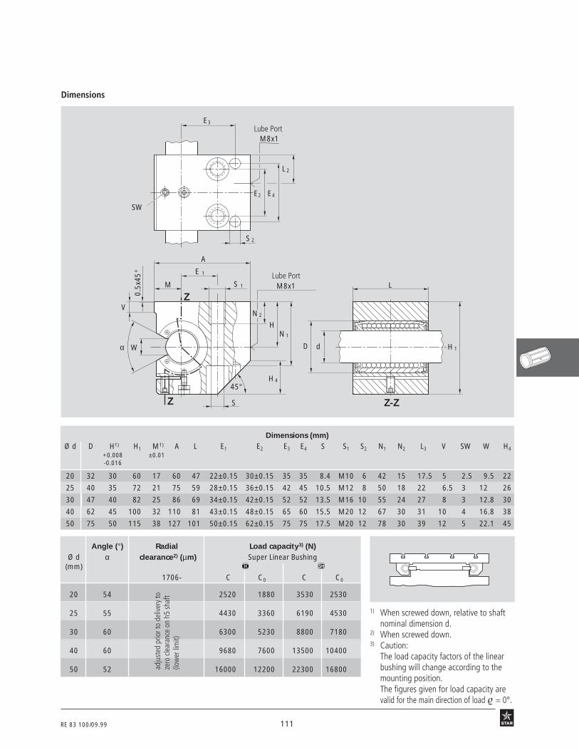
RE 83 100/09.99 111
Wα
V
0.5x
45°
A
E 1
M S 1
S
N 2
HN 1
M8x1 L
D d H 1
S 2
L 2
M8x1
E4E2
E3
SW
Z-ZZ
Z
H 445°
12 22 B2
Angle (°) Radial Load capacity3) (N)Ø d α clearance2) (µm) Super Linear Bushing
(mm)1706- C C0 C C0
20 54 2520 1880 3530 2530
25 55 4430 3360 6190 4530
30 60 6300 5230 8800 7180
40 60 9680 7600 13500 10400
50 52 16000 12200 22300 16800
1) When screwed down, relative to shaftnominal dimension d.
2) When screwed down.3) Caution:
The load capacity factors of the linearbushing will change according to themounting position.The figures given for load capacity arevalid for the main direction of load = 0°.
26 B 3a
Dimensions
Lube Port
adju
sted
prio
r to
deliv
ery
toze
ro c
lear
ance
on
h5 s
haft
(low
er li
mit)
Lube Port
Dimensions (mm)Ø d D H1) H1 M1) A L E1 E2 E3 E4 S S1 S2 N1 N2 L3 V SW W H4
+0.008 ±0.01-0.016
20 32 30 60 17 60 47 22±0.15 30±0.15 35 35 8.4 M10 6 42 15 17.5 5 2.5 9.5 22
25 40 35 72 21 75 59 28±0.15 36±0.15 42 45 10.5 M12 8 50 18 22 6.5 3 12 26
30 47 40 82 25 86 69 34±0.15 42±0.15 52 52 13.5 M16 10 55 24 27 8 3 12.8 30
40 62 45 100 32 110 81 43±0.15 48±0.15 65 60 15.5 M20 12 67 30 31 10 4 16.8 38
50 75 50 115 38 127 101 50±0.15 62±0.15 75 75 17.5 M20 12 78 30 39 12 5 22.1 45

112 RA 83 100.1
Due to their small overall dimensions,Compact Linear Bushings help to buildespecially neat stuctures.
Compact Linear Bushings are available in the followingtypes:• standard type
• type with reduced radial clearance (RT)
• corrosion-resistant type (anti-friction bearing steel to DIN 17230 / EN 10088)
• with or without seals
• Compact Linear Sets (linear bushing with housing) in various types
• Compact Linear Bushings are also available with STAR-Resist corrosionprotection (yellow chromatized zinc-iron coating)
Advantages• Radial clearance easily adjustable on Standard Shaft (h7 or h6 tolerance)
• High load capacity thanks to ball tracks in steel load bearing plates
• High travel speeds
• Internal wiper seals
• Low radial clearance
• No additional retaining elements required
• Available as corrosion-resistant type to DIN 17230 / EN 10088
• Low-cost solution to most problems
STAR – Compact Linear Bushings
The range and the design of linear motion elements have had to keep pace withthe emergence of new and changing demands on linear motion systems in recentyears. Part of STAR’s response to this challenge has been the development of theCompact Linear Bushing, the space-saving addition to its Linear Motion Program.

RA 83 100.1 113

114 RA 83 100.1
Please observe the general technical principles and mounting instructions at the beginning of this catalogas well as the additional technical data given below.
Sealing The sealed standard types are fitted with integral wiper-type seals.
Separate end seals can also be ordered (no special retaining elements necessary).
STAR – Compact Linear BushingsTechnical Data, Mounting Instructions
Friction The friction µ of unsealed Compact Linear Bushings using oil as a lubricant lies between0.001 - 0.004.
The friction is lowest under high load. It may, however, be greater than the stated valuewhen only a slight load is applied.
For Compact Linear Bushings fitted at both ends with internal wiper seals and not subjectto radial loading, the frictional drag (see table below) depends on the speed and the typeof lubrication.
Velocity vmax = 5 m/s
Acceleration amax = 150 m/s2
Operating temperature up to 100 °C
Shaft Breakaway force1) Frictional drag1)
Ø d (N approx.) (N approx.)(mm)
12 2 1
16 2.5 1.3
20 3 1.5
25 4.5 2
30 6 2.5
40 8 3
50 10 4
1) For separate wiper seals, the values must be multiplied by a factor of 1.5.

RA 83 100.1 115
The load capacities given are valid for installation in "min" position and should betaken as the basis for calculation.
In applications where the direction of load is exactly known and where the CompactLinear Bushings can be mounted in the "max" position, the load capacity rating must bemultiplied by the factors f max (dynamic load capacity C) or f0 max (static load capacity C0).
max.min.
max.
min.
Shaft Load capacityØ d factors
(mm) fmax f0 max
12, 16 1.19 1.46
20, 25, 30, 40, 50 1.26 1.48
18041803
0 20 40 60 80 100 120 140
1,0
0,5
0,6
0,7
0,8
0,9
160 180
16/2
0 25
30
12
40 50
fw
Notes for mounting Use of an arbor is recommended for installation of Compact Linear Bushings into thehousing bore (see "Mounting Instructions" in the General Technical Data at the beginningof this catalog).
If a Compact Linear Bushing is slightly skewed on entering the housing bore, it will alignitself as it is inserted further. Removal of the Compact Linear Bushing and re-alignment areunnecessary.
Retention No special retention elements are necessary, provided Compact Linear Bushings areinstalled in a bore according to the dimensions given in the tables.
Direction of load and its influence onthe load capacity
Stroke (mm)
Shaft Ø d12 and16
Shaft Ø d20 to 50
Reduced load capacity in short-strokeapplications
In short-stroke applications, the service life of the shafts is shorter than that of theCompact Linear Bushings.
For this reason, the load capacities C listed in the tables must be multiplied by the factor fw.

116 RA 83 100.1
Part numbersShaft without seals Mass
Ø d Compact Compact RT Compact (kg)(mm) corrosion-resistant
12 0658-012-00 0658-051-00 0658-012-30 0.016
16 0658-016-00 0658-052-00 0658-016-30 0.025
20 0658-020-00 0658-053-00 0658-020-30 0.028
25 0658-025-00 0658-054-00 0658-025-30 0.058
30 0658-030-00 0658-055-00 0658-030-30 0.080
40 0658-040-00 0658-056-00 0658-040-30 0.140
50 0658-050-00 0658-057-00 0658-050-30 0.170
STAR – Compact Linear Bushing
Structural design
• Ball retainer made of POM• Without seals• Internal/separate seals• Balls made of anti-friction bearing steel• Hardened steel segmental load bearing
plates• Metal holding rings
The figures for dynamic load-carryingcapacity have been calculated assuminga nominal travel of 100,000 m.For a nominal travel of 50,000 m, the 'C'figures in the table must be multiplied bya factor of 1.26.
Ordering data
Corrosion-resistant type(anti-friction bearing steel to DIN 17230 /EN 10088)
Corrosion-resistant Compact LinearBushings have the same overall dimen-sions as the standard type and arethus fully interchangeable with them.
• Balls made of corrosion-resistantantifriction bearing steel
• Corrosion-resistant steel segmental loadbearing plates
• Corrosion-resistant steel holding rings
Compact Linear Bushing, 0658-also in corrosion-resistant type
separate seals Shaft Part numbersØ d seal with
(mm) metal casing
12 1331-812-10
16 1331-816-10
20 1331-820-10
25 1331-825-10
30 1331-830-10
40 1331-840-10
50 1331-850-10
Part numbersShaft with two seals Mass
Ø d Compact Compact RT Compact (kg)(mm) corrosion-resistant
12 0658-212-40 0658-251-40 0658-212-30 0.016
16 0658-216-40 0658-252-40 0658-216-30 0.025
20 0658-220-40 0658-253-40 0658-220-30 0.028
25 0658-225-40 0658-254-40 0658-225-30 0.058
30 0658-230-40 0658-255-40 0658-230-30 0.080
40 0658-240-40 0658-256-40 0658-240-30 0.140
50 0658-250-40 0658-257-40 0658-250-30 0.170
With one seal: 0658-1..-40 or 0658-1..-30.
Compact RT typeWith reduced radial clearance for applica-tions requiring low-clearance operationwith H7 bores.

RA 83 100.1 117
Shaft Ø d12 and16
Shaft Ø d20 to 50
18 o 2 18 o 3 18 o 4
d
C
D
Dimensions (mm) No. of Radial clearance (µm) Load capacities3) (N)ball circuits shaft/bore standard corrosion-
resistant
Compact2), Compact corrosion-resistant2) Compact RT dyn. stat. dyn. stat.(reduced radial
clearance)Ø d D1) C h7/H7 h7/JS7 h6/JS6 h7/H7 C C0 C C0
±0.2
12 19 28 5+37 +26 +19 +13
730 420 510 340+2 –8 –8 –22
16 24 30 5+37 +26 +19 +13
950 500 660 400+2 –8 –8 –22
20 28 30 6+38 +28 +20 +14
1120 610 780 480+2 –9 –9 –22
25 35 40 6+42 +29 +21 +18
2330 1310 1630 1050+2 –10 –10 –22
30 40 50 6+42 +29 +21 +18
3060 1880 2140 1510+2 –10 –10 –22
40 52 60 6+48 +33 +23 +24
5040 3140 3520 2510+2 –13 –12 –22
50 62 70 6+48 +33 +23 +24
5680 3610 3970 2890+2 –13 –12 –22
s
1) The outer diameter of the metal holding ring is slightly oversize. No special retention elements are necessary(housing bore length ≥ C).
2) Tolerance K7 or K6 permissible in light-metal-alloy housings (slight preload possible).3) The load capacities stated are minimum values as the positions and direction of load cannot always be precisely defined.
Seal with metal casing
Dd
b
Dimensions (mm)
Ø d D4) b
12 19 3
16 24 3
20 28 4
25 35 4
30 40 4
40 52 5
50 62 5
4) The outer diameter D has been manufac-tured with an oversize of approx. 0.1 mm.No additional retention required.

118 RA 83 100.1
STAR – Compact Linear Sets
Shaft Part numbers MassØ d Compact Compact (kg)
(mm) corrosion-resistant1)
12 1027-212-40 1027-212-30 0.08
16 1027-216-40 1027-216-30 0.11
20 1027-220-40 1027-220-30 0.15
25 1027-225-40 1027-225-30 0.27
30 1027-230-40 1027-230-30 0.40
40 1027-240-40 1027-240-30 0.75
50 1027-250-40 1027-250-30 1.20
closed type
adjustable
Linear Sets 1028-2-... with adjustable radial clearance are adjusted to zero clearance(when screwed down) on a shaft of diameter accurate to a tolerance of h5 (lower limit)prior to delivery.
Compact Linear Sets, 1027-closed , standard or corrosion-resistant type
Compact Linear Sets, 1028-adjustable, standard type
Structural Design
• Precision Housing, lightweight series(aluminum)
• Compact Linear Bushing
• Two internal seals
48 b1r
49 b1r
The figures for dynamic load-carrying capacity have been calculated assuming a nominaltravel of 100,000 m.For a nominal travel of 50,000 m, the 'C' figures in the table must be multiplied by afactor of 1.26.
Ordering data
1) Linear Bushing, corrosion-resistant type (anti-friction bearing steel toDIN 17230 / EN 10088).
Shaft Part numbers MassØ d Compact (kg)
(mm)
12 1028-212-40 0.08
16 1028-216-40 0.11
20 1028-220-40 0.15
25 1028-225-40 0.27
30 1028-230-40 0.40
40 1028-240-40 0.75
50 1028-250-40 1.20

RA 83 100.1 119
49 b5
H
45°H4
AS1
N2N1
S
E
49 b 3
H1
SW
L
D d
Dimensions (mm)
Ø d D H H1 A L E S1) S1 N1 N2 H4 SW±0.15
12 19 17 33 40 28 29 4.3 M5 16 11 11 2.5
16 24 19 38 45 30 34 4.3 M5 18 11 13 2.5
20 28 23 45 53 30 40 5.3 M6 22 13 15 3
25 35 27 54 62 40 48 6.6 M8 26 18 17 4
30 40 30 60 67 50 53 6.6 M8 29 18 19 4
40 52 39 76 87 60 69 8.4 M10 38 22 24 5
50 62 47 92 103 70 82 10.5 M12 46 26 30 6
adju
sted
prio
r to
del
iver
y to
zer
ocl
eara
nce
on h
5 sh
aft
(low
er li
mit)
1) Mounting screws to ISO 4762-8.8.2) Relative to shaft nominal dimension d.3) The load capacities stated are minimum
values as the position and direction ofload cannot always be precisely defined.
Radial Tolerance Load capacities3) (N)clearance (µm) (µm)
Ø d 1027-… 1028-… Compact Compactcorrosion-resistant
dyn. stat. dyn. stat.
(mm) shaft for C C0 C C0
h6 h7 dimension H2)
12+32 +37 ±12 730 420 510 3400 +2
16+32 +37 ±12 950 500 660 4000 +2
20+33 +38 +13
1120 610 780 480–1 +2 –12
25+36 +42 +13
2330 1310 1630 10500 +2 –12
30+36 +42 +13
3060 1880 2140 15100 +2 –12
40+42 +48 +14
5040 3140 3520 2510–1 +2 –12
50+42 +48 +14
5680 3610 3970 2890–1 +2 –12

120 RA 83 100.1
STAR Segmental Linear Bushings –the low-cost solution
Segmental Linear Bushings are available in thefollowing versions:• standard type
• corrosion-resistant type (antifriction bearing steel to DIN 17230 / EN 10 088)
• without seals
• with separate seals
Advantages• Low noise
• Low weight
• Anti-corrosion steel shaft available to DIN 17230 / EN 10088
• Low price
STAR – Segmental Linear Bushings
The Segmental Linear Bushing is the least expensive of the Linear Bushing range.This time-tested machine element is also available in a corrosion-resistant version.In many fields, such as the food, film and photo industries, the corrosion-resistanttype offers appreciable advantages over conventional guide elements.Each load bearing plate has one ball track in which the balls roll.This ensures an optimum area of contact between the ball and the bearing plate,permitting better load distribution and thus higher load capacities than are attainablewith conventional types of linear bearings.

RA 83 100.1 121
16 o1a

122 RA 83 100.1
Please observe the general technical principles and mounting instructions at the beginning of this catalog aswell as the additional technical data given below.
STAR – Segmental Linear BushingsTechnical Data
The friction µ of unsealed Segmental Linear Bushings using oil as a lubricant lies between0.001 and 0.004.The friction is lowest under high load. It may, however, be greater than the stated valuewhen only a slight load is applied. The frictional drag (see table) in the linear bushingssealed at both ends and not subject to radial loading depends on the speed and the typeof lubrication.
Friction
Shaft Breakaway force Frictional drag
Ø d (N approx.) (N approx.)(mm)
12 3 1.5
16 4.5 2
20 5 2.5
25 7 3
30 9 4
40 12 5
Velocity vmax = 3 m/s
Acceleration amax = 150 m/s2
Operating temperature up to 100 °C
The stated load capacities are valid for installation in "min" position and should be takenas the basis for calculation.In applications where the direction of load is exactly known and where the SegmentalLinear Bushings can be mounted in the "max" position, the load capacity rating must bemultiplied by the factors fmax (dynamic load capacity C) or f0 max (static load capacity C0).
Direction of load and itsinfluence on the load capacity
Shaft Load capacityØ d factors
(mm) fmax f0 max
12, 16 1.19 1.46
20, 25, 30, 40 1.06 1.28
max.min.
10 b2

RA 83 100.1 123
0 20 40 60 80 100 120 140
1,0
0,5
0,6
0,7
0,8
0,9fw
40
1216
20 25
30
Mounting, Retention
RetentionRetention by means of a sealwith metal case
16 o 3
Retention by means of metal case
3 N 81
09 o 2
Reduced load capacity in short-strokeapplications
Operation under difficultconditions
In short-stroke applications, the service life of the shafts is shorter than that of theSegmental Linear Bushings.
For this reason, the load capacities C listed in the tables must be multiplied by the factor fw.
In permanently humid or wet environments due for instance to water-based coolants/lubricants, we recommend the use of the corrosion-resistant type to DIN 17230 /EN 10088.
Notes for mounting Use of an arbor is recommended for installation of Segmental Linear Bushings into thehousing bore (see "Mounting Instructions" in the General Technical Data at the begin-ning of this catalog).When Segmental Linear Bushings are mounted in an adjustable housing we recommendinstalling the linear bushing with one of its load bearing plates covering the slot in thehousing; this will prevent dirt from entering the linear bushing.
Stroke (mm)
separate seal
separate metal case

124 RA 83 100.1
STAR – Segmental Linear Bushings
1806
Shaft Part numbers
Ø d seal with metal case1) seal with corrosion- corrosion-resistant(mm) metal case resistant metal case metal case1)
12 1331-512-00 0901-043-00 1331-512-30 0901-043-30
16 1331-516-00 0901-044-00 1331-516-30 0901-044-30
20 1331-520-00 0901-045-00 1331-520-30 0901-045-30
25 1331-525-00 0901-046-00 1331-525-30 0901-046-30
30 1331-530-00 0901-047-00 1331-530-30 0901-047-30
40 1331-540-00 0901-048-00 1331-540-30 0901-048-30
Segmental Linear Bushings, 0668-standard or corrosion-resistant type
separate seals / metal case
Corrosion-resistant type
• Balls of corrosion-resistant antifrictionbearing steel
• Corrosion-resistant steel segmental loadbearing plates
• Ball retainer made of polyamide 11
Structural Design
• Balls made of anti-friction bearing steel• Hardened steel segmental load bearing
plates• Ball retainer made of polyamide
The figures for dynamic load-carrying capacity have been calculated assuming a nominal travel of 100,000 m.For a nominal travel of 50,000 m, the 'C' figures in the table must be multiplied by a factor of 1.26.
Shaft Part numbers Mass
Ø d standard corrosion-resistant (kg)(mm)
12 0668-012-00 0668-012-30 0.013
16 0668-016-00 0668-016-30 0.020
20 0668-020-00 0668-020-30 0.031
25 0668-025-00 0668-025-30 0.057
30 0668-030-00 0668-030-30 0.096
40 0668-040-00 0668-040-30 0.170
Ordering data
16 o 1r
1) for axial retention
(anti-friction bearing steelto DIN 17230 / EN 10088)The time-tested Segmental Linear Bushingis available in a corrosion-resistant versionfor use in hostile environment.In many fields, such as the food, film andphoto industries, the corrosion-resistanttype offers appreciable advantages overconventional linear guide elements.

RA 83 100.1 125
Dimensions
Segmental Linear Bushings (standardand corrosion-resistant types)
Corrosion-resistant Segmental LinearBushings have the same overall dimen-sions as standard Segmental LinearBushings and are thus fully interchange-able with them.
Dimensions (mm) No. of Radial clearance (µm) Load capacities1) (N)ball circuits shaft/bore standard corrosion-resistant
dyn. stat. dyn. stat.
Ø d D C h7/H7 h7/JS7 h6/JS6 C C0 C C0js 14
12 20 24 5+37 +26 +19
480 420 240 330+2 –8 –8
16 25 28 5+37 +26 +19
720 620 360 490+2 –8 –8
20 30 30 6+38 +28 +20
1020 870 510 690+2 –9 –9
25 37 37 6+42 +29 +21
1630 1360 820 1090+2 –10 –10
30 44 44 6+42 +29 +21
2390 1960 1200 1570+2 –10 –10
40 56 56 6+48 +33 +23
3870 3270 1940 2610+2 –13 –12
C
Dd
16 o 3
1) The load capacities stated are minimum values as the position and direction of load cannot always be precisely defined.
Seal with metal case/with corrosion-resistantsteel metal case
2) Outer diameter D is about 0.1 mm oversize. No special retention elements are necessary.
Dimensions (mm)
Ø d D2) b+0.3
12 20 3
16 25 3
20 30 4
25 37 4
30 44 5
40 56 5
Dd
b

126 RA 83 100.1
Structural Design
• Pillow Block Housing (reinforcedpolyamide)
• Segmental Linear Bushing
• Two seals with snap covers
• Bolt, washer, nut
• Adjustable radial clearance
Ordering data
35 o 1r
Shaft Part numbers Mass
Ø d standard corrosion-resistant1) (kg)(mm)
12 1060-212-00 1060-212-20 0.041
16 1060-216-00 1060-216-20 0.063
20 1060-220-00 1060-220-20 0.077
25 1060-225-00 1060-225-20 0.158
30 1060-230-00 1060-230-20 0.277
40 1060-240-00 1060-240-20 0.470
STAR – Linear Sets with Segmental Linear Bushings
Linear Sets, 1060-adjustable, standard orcorosion-resistant type
The figures for dynamic load-carrying capacity have been calculated assuming a nominal travel of 100,000 m.For a nominal travel of 50,000 m, the 'C' figures in the table must be multiplied by a factor of 1.26.
adjustable
1) Linear Bushing, corrosion-resistant type (anti-friction bearing steel to DIN 17230 /EN 10088).

RA 83 100.1 127
Dimensions
44 o 2 44 o 3
SH
A
E
V
d
B
H1
L
L
1
Dimensions (mm) Radial clearance Load capacities2) (N)(µm) standard corrosion-resistant
dyn. stat. dyn. stat.
Ø d H1) H1 L L1 A B E S V C C0 C C0±0.05
12 18 35 31 24 55 20 43±0.1 4.4 8 480 420 240 330
16 22 42 35 28 66 22 53±0.15 5.5 9.5 720 620 360 490
20 25 50 38 30 69 23 58±0.15 5.5 10.5 1020 870 510 690
25 30 60 46 37 87 30 72±0.2 6.6 11.5 1630 1360 820 1090
30 35 70 55 44 97 36 80±0.2 6.6 13 2390 1960 1200 1570
40 45 90 67 56 124 48 103±0.2 8.6 17 3870 3270 1940 2610
1) Relative to shaft nominal dimension d.2) The load capacities stated are minimum values as the position and direction of load cannot always be precisely defined.
adju
sted
prio
r to
del
iver
y to
zer
ocl
eara
nce
on h
5 sh
aft
(low
er li
mit)
128 RA 83 100.1
Machine tools, many special-purpose machines, transfer and automation equip-ment and similar applications frequently demand linear motion assemblies thatwork on the antifriction rolling bearing principle, and have high rigidity and load-carrying capacity.Radial Linear Bushings meet all these requirements.
Advantages over conventional machine guidewaysOther linear bearings
• Considerably higher load capacities allow space-saving design.
• Higher rigidity
• Smoother travel
Flat-way roller bearings
• Only 4 Radial Linear Bushings are required to support a twin-shaft table and take upforces acting in all directions. A conventional single-row roller bearing arrangementwould require 8 or even 12 elements, depending on the arrangement chosen, to givethe table the same degree of support.
• Higher rigidity, less variation in elastic deflection during operation, and lower frictionand smoother travel than many flat-way roller bearings.
Sliding ways
• Considerably lower friction and thus substantial power saving.
• Radial Linear Bushings are virtually wear-free and thus permit constantlow-clearance operation.
• No stick-slip effect.
Structural designThe load-carrying balls are continuously recirculated along a number of separate ballcircuits within the plastic ball retainer. As they reach the end of the load-carryingtracks they are lifted off radially outward and returned via the axial return bores backto the start of the load-carrying zone. While in the transition zone and the return bore,the balls run free from load. Each ball raceway forms a closed circuit, so that unlimitedtravel is possible.
The radial lift-off into the return bores makes it possible to incorporate more than twicethe ball circuits contained in conventional linear bearings, as well as increasing the lengthof the load-carrying zones. This significantly increases the rigidity and the load capacity ofthe linear motion assembly.
STAR – Radial Linear Bushings

RA 83 100.1 129
24 o 1
Radial Linear Bushing Conventional linear bearing This diagram shows how the highload capacity permits a considerablereduction in dimensions.
Ø 50 mm C = 8470 NØ 30 mm C = 8500 N
2402 2403

130 RA 83 100.1
Please observe the general technical principles and mounting instructions at the beginning of thiscatalog as well as the additional technical data given below.
STAR – Radial Linear BushingsTechnical Data
Friction The coefficient of friction µ of unsealed Radial Linear Bushings lies between 0.001 and0.002. This low friction coefficient makes it possible to move heavy loads with a minimumof power consumption.
Radial Linear Bushings with separate seals or fully sealed achieve the following frictionratings.
Sealing Radial Linear Bushings can be supplied
• fully sealed with internal wiper-type seals and axial seal strip, or
• with separate seals specially designed for use with Radial Linear Bushings.
Velocity vmax = 2 m/s
Acceleration amax = 50 m/s2
Operating temperature up to 100 °Cwith separate seals 80 °C, brief peaks up to 100 °C
Shaft Separate Seals Fully sealedØ d Breakaway force Frictional drag Breakaway force Frictional drag
(mm) (N approx.) (N approx.) (N approx.) (N approx.)
30 24 8 24 12
40 32 11 32 16
50 40 14 40 20
60 48 16 48 24
80 60 20 60 30
Direction of load and its influenceon the load capacity
The load capacity ratings C and C0 given for Radial Linear Bushings apply when the loadis acting along the line = 0°. If the external load acts at an angle = 90° to 270°,allowance must be made for a reduction in load capacity by multiplying the load capaci-ties C and C0 by the load capacity factors f and f 0 .The reduction in the load capacity can be minimized by selective circumferential posi-tioning of the Radial Linear Bushings.
Load capacity factors
0.6
0.4
1.0
0.8
0°
30°
300°
270°
240°
210°
180°
150°
120°
90°
60°
330°
( )°f ο
f ο
f
f
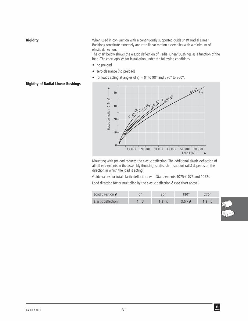
RA 83 100.1 131
26 0 1 60 00050 000
∂ [m
m]
40 00030 00020 00010 0000
10
20
30
40
d= 3
0 d= 40 d= 50
d= 60d= 80
Co
Co
Co
Co
Co
Rigidity When used in conjunction with a continuously supported guide shaft Radial LinearBushings constitute extremely accurate linear motion assemblies with a minimum ofelastic deflection.The chart below shows the elastic deflection of Radial Linear Bushings as a function of theload. The chart applies for installation under the following conditions:
• no preload
• zero clearance (no preload)
• for loads acting at angles of = 0° to 90° and 270° to 360°.
Rigidity of Radial Linear Bushings
Load direction 0° 90° 180° 270°
Elastic deflection 1 · ∂ 1.8 · ∂ 3.5 · ∂ 1.8 · ∂
Mounting with preload reduces the elastic deflection. The additional elastic deflection ofall other elements in the assembly (housing, shafts, shaft support rails) depends on thedirection in which the load is acting.
Guide values for total elastic deflection: with Star elements 1075-/1076 and 1052-:
Load direction factor multiplied by the elastic deflection ∂ (see chart above).
Elas
tic d
efle
ctio
n
Load F [N]

132 RA 83 100.1
STAR – Radial Linear BushingsMounting, Retention
2702
2701
Installation, retention
Lubricating instructions
The tolerances for the housing bore can be taken from the table for Radial LinearBushings. The housing may have a slot and adjusting screw at one side for establishingthe desired clearance or preload. Radial Linear Bushings are also available as part ofLinear Sets complete with matching housing. For details on permissible parallelism offset,please refer to the "General Technical Data and Mounting Instructions" at the beginningof this catalog.
Lubricate only with shaft inserted; add lubricant until excess emerges.
To prevent damage to the assembly during installation, it is essential that Radial LinearBushings be inserted into the housing with the aid of a press or bearing extractor. Thefollowing instructions and illustrations should be observed during installation.The outer sleeve of the Radial Linear Bushing and the surface of the mounting bore in thehousing must be free from all oil residue before commencement of installation.
For maximum rigidity, Radial Linear Bushings must be installed on continuously supportedshafts. Our Linear Motion product range includes steel shaft support rails in standardlengths of 600 mm. The Radial Bushings must be inserted into the housings as describedin the mounting procedure.In applications where vibration or high acceleration rates are to be anticipated, and in parti-cular for vertical installations, use of some additional means of retention is recommended.The following assembly sequence should always be observed: first bolt the shafts to theshaft supports, then align the housings with the Radial Linear Bushings on the shafts, andonly then bolt the assembly to the table.
Recommended tolerances
Procedure for mountingRadial Linear Bushings
Slip a slotted mounting ring (order number0940-0..-00) over the linear bushing asshown and reduce the outside diameter ofthe linear bushing by tightening the adjust-ing screw until it can easily be peared intothe housing bore by hand. The bore of themounting ring must be about 0.5 mmlarger than the outside diameter D of theRadial Linear Bushing.
After pushing the Radial Linear Bushinginto the housing, but before loosening themounting ring, match up the opening ofthe Radial Linear Bushing with the openingin the housing. The mounting ring can nowbe loosened.

RA 83 100.1 133
2704
2703
Notes
• If the openings of the Radial Linear Bushing and the housing do not match up when thelinear bushing is mounted:- push out the Radial Linear Bushing (by means of the press or bearing extractor)- fit the mounting ring- correct the position of the linear bushing opening- continue the installation according to the photos and instructions above.
• The ends of the shaft must be chamfered.
• The Radial Linear Bushing must not be allowed to tilt while being pushed onto theshaft.
• Relative rotation between the shaft and the Radial Linear Bushing should be avoided.
• If external seals are used, these must be aligned with the Radial Linear Bushing andinserted by means of a press or bearing extractor.
Use a press to push the pre-aligned RadialLinear Bushing firmly into the housing.
Alternatively, the pre-aligned Radial LinearBushing can be pushed into the housingwith the aid of a bearing extractor. In thiscase, the extractor spindle must be joinedto the pressure plate via a ball bearing(see arrow). Otherwise, a separate thrustbearing must be provided in front of theextractor spindle to prevent the RadialLinear Bushing from being turned in thehousing by torque exerted by the bearingextractor.

134 RA 83 100.1
STAR – Radial Linear Bushings
Load capacity factorsRadial Linear Bushings,0678-without seal or fully sealed
Ordering data
24 o 1r
71B5
Structural Design
• Hardened and ground steel sleeve
• Reinforced polyamide ball retainer
• Balls made of anti-friction bearing steel
• Two snap rings
For load capacities, see "Technical Data".
Shaft Part numbers Mass
Ø d without seals fully sealed(mm) (kg)
30 0678-030-00 0678-230-45 0.7
40 0678-040-00 0678-240-45 1.4
50 0678-050-00 0678-250-45 2.5
60 0678-060-00 0678-260-45 4.9
80 0678-080-00 0678-280-45 10.4
The figures for dynamic load-carrying capacity have been calculated assuming a nominal travel of 100,000 m.For a nominal travel of 50,000 m, the 'C' figures in the table must be multiplied by a factor of 1.26.
Shaft Part numbers MassØ d
(mm) (kg)
30 1331-930-00 0.050
40 1331-940-00 0.075
50 1331-950-00 0.145
60 1331-960-00 0.230
80 1331-980-00 0.400
separate seals
0.6
0.4
1.0
0.8
0°
30°
300°
270°
240°
210°
180°
150°
120°
90°
60°
330°
( )°f ο
f ο
f
f

RA 83 100.1 135
Dimensions
Dimensions (mm) No. of ball Radial clearance (µm) Load capacities3)
circuits shaft/bore dyn. stat.
Ø d D C W2) S1 h6/H6 h6/JS61) h6/K61) C C0
h11 (N) (N)
30 60 75 14 3 12+21 +12 +6
8500 9520–10 –20 –25
40 75 100 19.5 3 12+23 +13 +8
13900 16000–13 –22 –28
50 90 125 24.5 3 12+25 +14 +7
20800 24400–12 –23 –30
60 110 150 29 4 12+26 +15 +8
29500 34100–15 –26 –33
80 145 200 39 4 12+29 +16 +8
54800 61500–15 –27 –36
1) Caution: travel life may be shortened by excessive preload (see tables TB-06-052-05 and -06).2) Lower limit relative to shaft diameter d.3) The stated load capacities apply when the load is acting along the line = 0°.
C
d
S 1
W
72°
D
25o1
Fully sealed
4) Outer diameter D is about 0.1 mm oversize. No retaining elements required except forapplications subject to vibration or high acceleration.
2602
Dimensions (mm)
Ø d D4) b
30 60 5
40 75 5
50 90 7
60 110 7
80 145 7
b
d
D
73 °
Separate seals
Lube port S1 at center
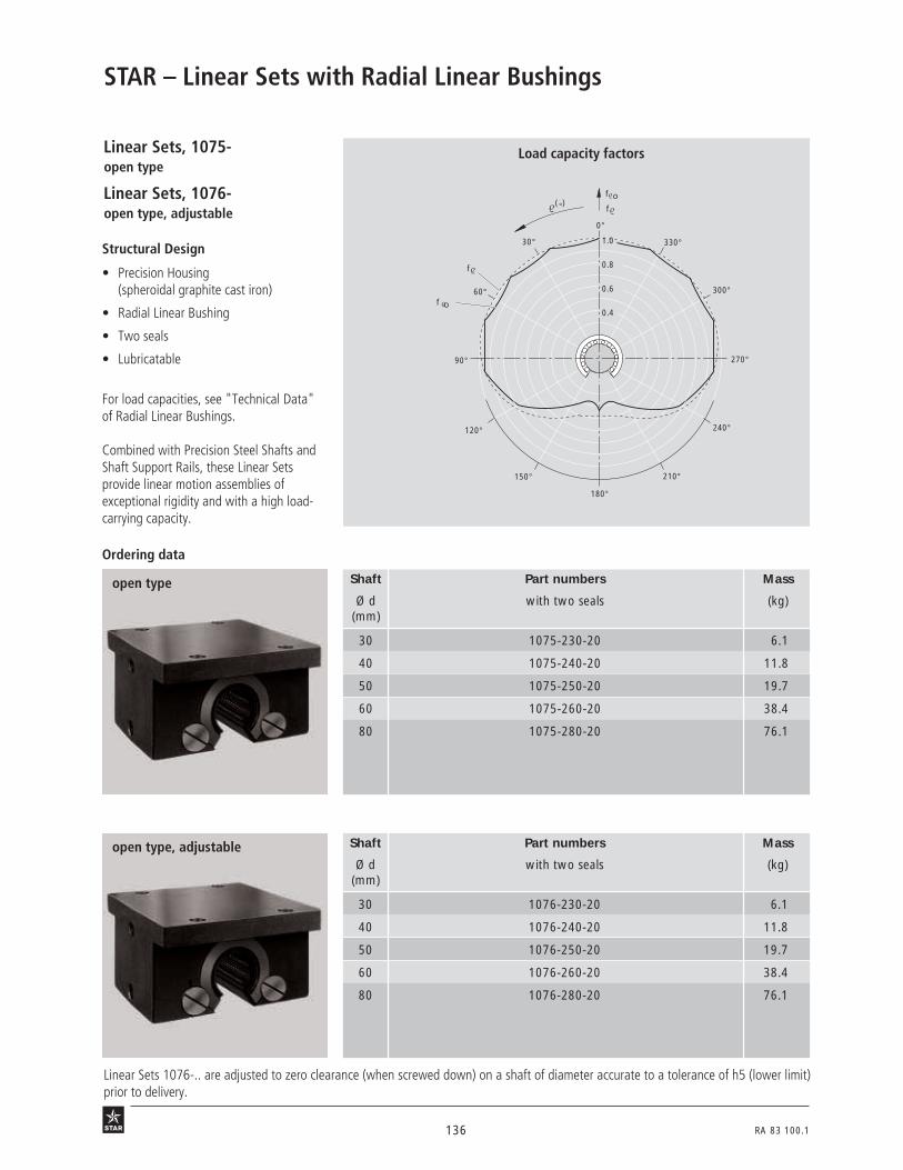
136 RA 83 100.1
STAR – Linear Sets with Radial Linear Bushings
Structural Design
• Precision Housing(spheroidal graphite cast iron)
• Radial Linear Bushing
• Two seals
• Lubricatable
For load capacities, see "Technical Data"of Radial Linear Bushings.
Combined with Precision Steel Shafts andShaft Support Rails, these Linear Setsprovide linear motion assemblies ofexceptional rigidity and with a high load-carrying capacity.
Load capacity factors
Ordering data
Shaft Part numbers Mass
Ø d with two seals (kg)(mm)
30 1075-230-20 6.1
40 1075-240-20 11.8
50 1075-250-20 19.7
60 1075-260-20 38.4
80 1075-280-20 76.1
5 n 1 r
open type
open type, adjustable Shaft Part numbers Mass
Ø d with two seals (kg)(mm)
30 1076-230-20 6.1
40 1076-240-20 11.8
50 1076-250-20 19.7
60 1076-260-20 38.4
80 1076-280-20 76.1
Linear Sets 1076-.. are adjusted to zero clearance (when screwed down) on a shaft of diameter accurate to a tolerance of h5 (lower limit)prior to delivery.
Linear Sets, 1075-open type
Linear Sets, 1076-open type, adjustable
0.6
0.4
1.0
0.8
0°
30°
300°
270°
240°
210°
180°
150°
120°
90°
60°
330°
( )°f ο
f ο
f
f
45 o 1 r
71B5
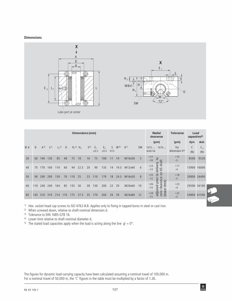
RA 83 100.1 137
Dimensions 45o2 45o3
adju
sted
prio
r to
del
iver
y t
oze
ro c
lear
ance
on
h5 s
haft
(low
er li
mit)
1) Hex. socket head cap screws to ISO 4762-8.8. Applies only to fixing in tapped bores in steel or cast iron.2) When screwed down, relative to shaft nominal dimension d.3) Tolerance to DIN 1685-GTB 16.4) Lower limit relative to shaft nominal diameter d.5) The stated load capacities apply when the load is acting along the line = 0°.
dDA
LL 1E 2
X
H1
S
W72°
H
H2
M8x1
E 1
V
O
SW
X
The figures for dynamic load-carrying capacity have been calculated assuming a nominal travel of 100,000 m.For a nominal travel of 50,000 m, the 'C' figures in the table must be multiplied by a factor of 1.26.
Lube port at center
Dimensions (mm) Radial Tolerance Loadclearance capacities5)
(µm) (µm) dyn. stat.
Ø d D A3) L3) L13) H H1
3) H2 V3) E1 E2 S W4) O1) SW 1075-… 1076-… for C Co
±0.5 ±0.5 H13 shaft h6 dimension H2)(N) (N)
30 60 140 130 85 48 75 18 16 75 108 11 14 M10x30 5+21 +15
8500 9520–10 –5
40 75 170 160 110 60 94 22.5 20 90 135 14 19.5 M12x40 6+23 +17
13900 16000–13 –4
50 90 200 200 139 70 110 25 23 110 170 18 24.5 M16x50 8+25 +18
20800 24400–12 –5
60 110 240 240 164 85 135 30 28 130 200 22 29 M20x60 10+26 +23
29500 34100–15 –4
80 145 310 310 214 110 175 37.5 35 170 260 26 39 M24x80 12+29 +22
54800 61500–15 –5

138 RA 83 100.1
STAR – Linear Sets with Radial Linear Bushings
Structural Design
• Precision Housing with side opening(spheroidal graphite cast iron)
• Radial Linear Bushing
• Two seals
• Lubricatable
The load carrying capacity of open linearbushings is considerably reduced when theload is applied to the "open" portion of thebushing.This Linear Set has been developed to allowlateral installation of the Radial LinearBushing and thus full utilization of the highload capacity rating.
Load capacity factorsLinear Sets, 1077-with side opening
Linear Sets, 1078-with side opening, adjustable
Shaft Part numbers Mass
Ø d with two seals (kg)(mm)
30 1077-230-20 6.5
40 1077-240-20 13
50 1077-250-20 23
60 1077-260-20 40
80 1077-280-20 87
with side opening
Shaft Part numbers Mass
Ø d with two seals (kg)(mm)
30 1078-230-20 6.5
40 1078-240-20 13
50 1078-250-20 23
60 1078-260-20 40
80 1078-280-20 87
with side opening, adjustable
5n2 r
Linear Sets 1078-.. are adjusted to zero clearance (when screwed down) on a shaft of diameter accurate to a tolerance of h5 (lower limit)prior to delivery.
Ordering data
0.6
0.4
1.0
0.8
0°
30°
300°
270°
240°
210°
180°
150°
120°
90°
60°
330°
f
(°)
f
f o
f o
Note:The diagram above corresponds to a mounting position as given in the photo below andtherefore differs from the illustration given under "Technical Data".
35o5 r
3N68

RA 83 100.1 139
Dimensions46 o 1 46 o 2
E 2L 2
SW1
SW2
A1
A
Radial Tolerance Load capacities4)
clearance (µm) (µm) dyn. stat.
Ø d 1077-… 1078-… for dimension C C0
(mm) shaft h6 H3) (N) (N)
30+21 +15
8500 9520–10 –5
40+23 +17
13900 16000–13 –4
50+25 +18
20800 24400–12 –5
60+26 +23
29500 34100–15 –4
80+29 +22
54800 61500–15 –5
1) Tolerance to DIN 1685-GTB 162) Hex. socket head cap screws to DIN 6912-8.8. Applies only for
fixing in tapped bores in steel or cast iron.3) When screwed down, relative to shaft nominal dimension d.4) The load capacities apply when the load is acting along the line
shown by the arrows at FH1 or FH2.
V1
V
M8x1
SE 3
E 4
A2
WH1
H72° O
Dimensions (mm)
Ø d D A1) A11) A2
1) L1) L11) L2
1) H H11) V1) V1 E2 E3 E4 S W SW1 SW2 O2)
±0.5 ±0.5 ±0.5
30 60 110 83 27 140 85 18 48 118 18 11 110 28 65 13.5 14 17 5 M12x30
40 75 135 100 35 180 110 25 60 145 25 15 142 40 76 17.5 19.5 19 6 M16x40
50 90 165 125 40 230 139 30 70 170 30 17.5 180 50 95 22 24.5 24 8 M20x50
60 110 200 150 50 275 164 35 85 205 35 20.5 215 60 115 26 29 30 10 M24x60
80 145 265 200 65 345 214 45 110 265 45 25.5 275 75 155 33 39 36 12 M30x80
F0 = 0.95 · C0 FU = 0.95 · C0
FH1 = C0 FH2 = C0
Maximum permissible loads:
F 0
F U
F 0
F U
F H2F H1
46 o 4 26 B 3
The figures for dynamic load-carrying capacity have been calculat-ed assuming a nominal travel of 100,000 m.For a nominal travel of 50,000 m, the 'C' figures in the table mustbe multiplied by a factor of 1.26.
Lube portat center
L L 1
d
Dad
just
ed p
rior
to d
eliv
ery
toze
ro c
lear
ance
on
h5 s
haft
(low
er li
mit)

140 RA 83 100.1
Radial Sets and Radial Compact Sets provide the same high load-carrying capacity – and hence the same long life service life – as RadialLinear Bushings. Both elements incorporate the design principle of radial ball lift-off at the end of the load-carrying zone.
STAR – Radial Compact Sets
Advantages
Compared with the time-tested Linear Sets with Radial Linear Bushings, Radial Compact Sets offer decided advantages:
• Lower overall height and width.The compact build was achieved by integrating the housing and the linear bushing intoone element.
• Lower weight.
• High dimensional accuracy – closer tolerancesRadial clearance: up to 50% betterHeight: up to 25% better
• Fully sealed due to wiper-type seals and axial seal strip in the opening.
• Fitting edge for greater ease of mounting.
• Ready-drilled bores for locating pins.
The Set can be paired with a Precision Steel Shaft and a specially modified Steel ShaftSupport Rail (see Chapter "Shaft Support Rails"). This combination affords the machinedesigner the following benefits:
• Lower and narrower shaft support rail.
• Easy installation for diameters 30 to 50, which can be supplied in one piece withready-mounted shaft up to a length of 3000 mm.
• Parallelism of shaft relative to mounting base improved by 25%, thus giving moreprecise guidance over lengths up to 3000 mm in sizes 30 to 50.
• Fitting edge on the shaft support rail to facilitate mounting.

RA 83 100.1 141
69 b 1 r

142 RA 83 100.1
70 b 3
70 b 2
Ø d (mm) 30 40 50 60 80
ISO 4762-8.8 M10x30 M12x40 M16x50 M20x60 M24x80
Mounting procedure
STAR – Radial Compact SetsTechnical Data/Mounting InstructionsFriction, velocity, acceleration,operating temperature and directionof load and its influence on the loadcapacity and rigidity
Prior to installation
Shaft Support Rails cut to fit the machine base (low overall height)
• Fabricate the shaft support rails to the specified parallelism (see section on "Paralle-lism, General Technical Data and Mounting Instructions").
• Screw on the shafts.
• Mount the Radial Compact Sets (see Chapter "Shaft Support Rails"). Alternatively, theRadial Compact Sets may be installed according to the Chapter "Shaft Support Rails".
Recommended mounting screws for installation of shaft
Check the flatness of the base on which the Radial Compact Set is to be mounted, asirregularities will affect the radial clearance. The shaft ends must be chamfered. Take carenot to tilt the Radial Compact Sets while pushing them onto the shaft.
With STAR Shaft Support Railssee Chapter "Shaft Support Rails".
The values given for Radial Linear Bushings may be used for design purposes.
Shaft Breakaway force Frictional drag
Ø d (N approx.) (N approx.)mm
30 24 12
40 32 16
50 40 20
60 48 24
80 60 30
Frictional drag for seals withoutradial loading
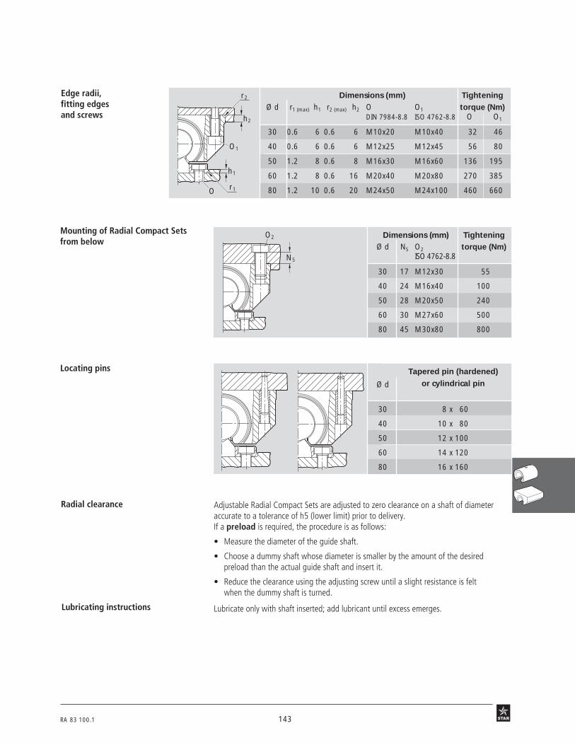
RA 83 100.1 143
Dimensions (mm) TighteningØ d r1 (max) h1 r2 (max) h2 O O1 torque (Nm)
DIN 7984-8.8 ISO 4762-8.8 O O1
30 0.6 6 0.6 6 M10x20 M10x40 32 46
40 0.6 6 0.6 6 M12x25 M12x45 56 80
50 1.2 8 0.6 8 M16x30 M16x60 136 195
60 1.2 8 0.6 16 M20x40 M20x80 270 385
80 1.2 10 0.6 20 M24x50 M24x100 460 660
71 b 1
71 b 2
Dimensions (mm) TighteningØ d N5 O2 torque (Nm)
ISO 4762-8.8
30 17 M12x30 55
40 24 M16x40 100
50 28 M20x50 240
60 30 M27x60 500
80 45 M30x80 800
Tapered pin (hardened)
Ø d or cylindrical pin
30 8 x 60
40 10 x 80
50 12 x 100
60 14 x 120
80 16 x 160
h2
r2
O1
h1
r1O
N5
O2
Edge radii,fitting edgesand screws
Mounting of Radial Compact Setsfrom below
Locating pins
Radial clearance
Lubricating instructions
Adjustable Radial Compact Sets are adjusted to zero clearance on a shaft of diameteraccurate to a tolerance of h5 (lower limit) prior to delivery.If a preload is required, the procedure is as follows:
• Measure the diameter of the guide shaft.
• Choose a dummy shaft whose diameter is smaller by the amount of the desiredpreload than the actual guide shaft and insert it.
• Reduce the clearance using the adjusting screw until a slight resistance is feltwhen the dummy shaft is turned.
Lubricate only with shaft inserted; add lubricant until excess emerges.
71 b 471 b 3

144 RA 83 100.1
STAR – Radial Compact Sets
Radial Compact Sets, 1611-open type
Radial Compact Sets, 1613-open type, adjustable
Structural Design
• Hardened and ground bearing blockmade of anti-friction bearing steel
• Reinforced polyamide ball retainer
• Balls made of anti-friction bearing steel
• Two snap rings
• Fully sealed (with internal wiper-typeseals and seal strip)
Ordering data
open type
open type, adjustable
Shaft Part numbers Mass
Ø d (kg)(mm)
30 1611-300-00 1.75
40 1611-400-00 3.5
50 1611-500-00 7.1
60 1611-600-00 11.9
80 1611-800-00 29.6
68 b 4r
68 b 6 rShaft Part numbers Mass
Ø d (kg)(mm)
30 1613-300-00 1.75
40 1613-400-00 3.5
50 1613-500-00 7.1
60 1613-600-00 11.9
80 1613-800-00 29.6
71B5
0.6
0.4
1.0
0.8
0°
30°
300°
270°
240°
210°
180°
150°
120°
90°
60°
330°
( )°f ο
f ο
f
f
Load capacity factors
The figures for dynamic load-carrying capacity have been calculated assuming a nominal travel of 100,000 m.For a nominal travel of 50,000 m, the 'C' figures in the table must be multiplied by a factor of 1.26.

RA 83 100.1 145
Dimensions 68 b 268 b 1
N 2
A
S1 A1
N3N1
S W
72°
V2 HH1
d
S
E 1
2 LE 2
A
H
H 2SW
A2
Adjustable radial clearance
Dimensions (mm) Radial Loadclearance (µm) capacities4)
shaft h6 dyn. stat.
Ø d A A1 A2 H1) H1 H2 L E1 E2 S S1 S22) N1 N2 N3 V2 W3) SW 1611- 1613- C C0
±0.008 ±0.008 (N) (N)
30 100 50 68 32 53 65 75 76 40 10.5 M12 7.7 21 15 9 6 14 5+10
8500 9520–6
40 125 62.5 85 40 66 80 100 94 50 13.8 M16 9.7 27 18 11 6 19.5 6+12
13900 16000–7
50 160 80 105 50 81.5 100 125 122 65 17.5 M20 11.7 35 24 12 8 24.5 8+12
20800 24400–7
60 190 95 130 60 97 120 150 150 75 22 M27 13.7 42 32 13 16 29 10+15
29500 34100–9
80 260 130 170 80 130 160 200 205 100 26 M30 15.7 57 36 15 16 39 12+15
54800 61500–9
1) When screwed down, relative to shaft nominal dimension d.2) Pre-drilled bores for locating pins.3) Lower limit relative to shaft nominal dimension d.4) The load capacities apply when the load is acting along the line = 0°.
68 b 568 b 3
Lube port M8x1
Shaft with Shaft Support Rail 1012-(see Chapter "Shafts with Shaft Support Rails”)
adju
sted
prio
r to
del
iver
y to
zero
cle
aran
ce o
n h5
sha
ft(lo
wer
lim
it)

146 RA 83 100.1
The Torque-Resistant Linear Bushing makes it possible to obtain axially andradially true linear motion with just one shaft. Its space-saving design makes itsuitable for use in numerous jig and special-purpose machinery applications.
Torque-Resistant Linear BushingsTorque-Resistant Linear Bushings are similar in their structural design to the alreadyfamiliar Super Linear Bushings . The torque is transmitted between extra-deep ballraces with special hardened steel load bearing plates in the linear bushings and ball guidegrooves in the precision steel shaft. Two types are available: Type 1 with one ball guidegroove and Type 2 with two ball guide grooves. The type required for any given applica-tion will depend on the magnitude of the torque to be transmitted.
Linear Sets with Torque-Resistant Linear BushingsThe version with a steel housing is extremely sturdy.The comparatively low weight of the high-strength aluminum housing is of great advan-tage wherever applications call for higher acceleration and faster positioning speeds. Thealuminum version is lubricatable.This makes them ideal for use in many branches of mechanical and tool engineering andhandling technology.
The advantages:Compact block design
The Torque-Resistant Linear Bushing is completely enclosed in the compact housing toprotect it against all external impacts.
Easy to mount
with only two mounting screws. No need to align two shafts in parallel. No reduction ofservice life due to out-of-parallelism.
High precision
and trouble-free running thanks to the high-strength housing design and integral Torque-Resistant Linear Bushing.
Zero-clearance guidance
The steel load bearing plates that transmit the torque are adjusted to zero clearance bymeans of the adjusting screws before the Linear Sets leave the factory.
Torque-Resistant Compact Linear BushingsTorque-Resistant Compact Linear Bushings have the same basic structural design asTorque-Resistant Linear Bushings, the one difference being the adjusting screws and locknuts. These are even smaller in order to reduce the overall dimensions still further to allowmounting in narrower sleeves.
Linear Sets with Torque-Resistant Compact LinearBushingsLinear Sets with Torque-Resistant Compact Linear Bushings are self-contained unitscomprising a Torque-Resistant Compact Linear Bushing and a sleeve.When mounted in tandem they provide stability in applications with cocking loads, thusallowing higher permissible torque levels.A version with a flanged housing is also available.
STAR – Torque-Resistant Linear Bushings

RA 83 100.1 147
53 b 1ar
59 B 1b r

148 RA 83 100.1
STAR – Torque-Resistant Linear BushingsOverviewTorque-Resistant Linear Bushings
3N 91
3N 90
3N 92
with one ball guide groove
with two ball guide grooves
Type 1
Type 2
Torque-Resistant Compact Linear Bushing

RA 83 100.1 149
Technical Data
Please observe the general technical principles and mounting instructions at the beginning of thiscatalog as well as the additional technical data given below.
F = equivalent total load (N)FR = radial load (N)C = dynamic load capacityM = torque (Nm)Mt = torque (catalog rating) (Nm)L = travel life
M = torque (Nm)Mt = torque (catalog rating) (Nm)M1, M2 … Mn = discrete torque steps (Nm)q1, q2 … qn = percentage stroke
covered under M1, M2 … Mn (%)
Load capacity and travel life
In applications subject to torque only, travel life is calculated as follows:
In applications subject to superimposed radial loads and torque, the equiva-lent total load must first be calculated for use in the travel life calculation.
12 B 3.2
Reduced load capacity in short-strokeapplications
In short-stroke applications, the service life of the shafts is shorter than that of the Torque-Resistant Linear Bushings.
For this reason, the load capacities C listed in the tables must be multiplied by the factor fw.
up to 100 °COperating temperature
To ensure stability against cocking loads it is expedient to install two Torque-ResistantLinear Bushings.
In the case of Linear Sets, we recommend the Tandem version (with two Torque-ResistantLinear Bushings).
- up to 1200 mm length: 0.1 mm
- at 2000 mm length: 0.2 mm
Straightness of shaft
Stability against cocking loads
L = ( )3 · 105 m
C
F
L = ( )3 · 105 m
Mt
M
L = FR +C · M
Mt
M = 3 M13 · + M2
3 · +......+ Mn3 ·
q1
100
q2
100
qn
100
Stroke (mm)0 20 40 60 80 100 120 140
1,0
0,5
0,6
0,7
0,8
0,9
fw
160 180 200 220 240 260
5016
12
2025 30 40 50
16
12
2025 30 40

150 RA 83 100.1
60.1 b 1
STAR – Torque-Resistant Linear Bushings
Mounting procedure Linear Sets are ready-mounted and adjusted to zero clearance. If theshaft has been removed, it is necessary to loosen the adjusting screwsand re-adjust the Torque-Resistant Linear Bushing.
- Chamfer and clean the bore (1) in the housing (2).
- Oil the adjusting screw (3).
- Check the lock nut (4) on the adjusting screw (3) for ease of movement.
- Check the adjusting screw (3) in the tapped hole (5) for ease of movement.Deburr thread runout, if necessary.
- Remove transport packing from the linear bushing.
Do not drive in linear bushings with a hammer!
- Insert linear bushing (9) in the housing (2) by hand.
- Align countersunk steel bearing plate (8) with the tapped hole (5) in the housing.
- Align one ball guide groove (6) with the marking (7) on the identification block of thelinear bushing.
- Insert shaft, taking care not to tilt it!
- Screw in adjusting screw until it meets with initial resistance.
- Move shaft to and fro, while simultaneously attempting to turn it in both directions.Tighten adjusting screw with hex. wrench.
- For type 1 (one ball guide groove), tighten adjusting screw to MGA.
- For type 2 (two ball guide grooves), first tighten one adjusting screw to MGA/2, thenthe other to MGA.
- Secure adjusting screw with lock nut. Use face wrench (1). The adjusting screw mustnot turn when being secured with the lock nut. Tightening torque = MGK.
- After mounting, the frictional drag FR should be as shown in the table below. If thefrictional drag varies significantly, loosen and re-adjust adjusting screws!
- Do not remove shaft!
STAR
6
1 2
43
7 8
9
5
43
Adjustment of adjusting screws
- Push seal onto the shaft, aligning the lip with the groove.
- Press seal into the mounting bore.
With each installed seal the frictional drag rises higher than the value FR. If two seals areinstalled, it increases to roughly three times the value stated in the table.
Installation of seal
s
1
12 16 20 25 30 40 50
2.5 2.5 3 3 3 3 3
10 10 15 15 19.5 19.5 25
8 11 30 45 70 100 180
400 400 1500 1500 2000 2000 3000
1.5 2 3 4.5 6 8 12
Shaft diameter (mm)
Face s (mm)
wrench (1) A (mm)
Tightening adjusting screw MGA (Ncm)
torque lock nut MGK (Ncm)
Frictional drag FR approx. (N)(one linear bushing)
Mounting of Torque-Resistant Linear Bushings

RA 83 100.1 151
60.2 b 1
Mounting of Torque-Resistant Compact Linear Bushings
Mounting procedure Linear Sets are ready-mounted and adjusted to zero clearance. If theshaft has been removed, it is necessary to loosen the adjusting screwsand re-adjust the Torque-Resistant Compact Linear Bushing.
- Chamfer and clean the bore (1) in the housing (2).
- Oil the adjusting screw (3) and lock screw (4).
- Check the lock screw (4) in the adjusting screw (3) for ease of movement.
- Check the adjusting screw (3) in the tapped hole (5) for ease of movement. Deburrthread runout, if necessary.
- Remove transport packing from the linear bushing.
Do not drive in linear bushings with a hammer!
- Insert linear bushing (9) in the housing (2) by hand.
- Align countersunk steel bearing plate (8) with the tapped hole (5) in the housing.
- Align one ball guide groove (6) with the marking (7) on the identification block of thelinear bushing.
- Insert shaft, taking care not to tilt it!
STAR
4 3
43
5
12
87
9
6
Adjustment of adjusting screws - Screw in adjusting screw until it meets with initial resistance.
- Move shaft to and fro, while simultaneously attempting to turn it in both directions.Tighten adjusting screw with screwdriver (1).
- For shaft diameters 12 and 16, tighten adjusting screw to MGA.
- For shaft diameters 20 to 50, first tighten one adjusting screw to MGA/2, then the otherto MGA.
- Using a face wrench (2), insert lock screw into the adjusting screw and tighten totightening torque MGK.
- After mounting, the frictional drag FR should be as shown in the table below. If thefrictional drag varies significantly, loosen and re-adjust adjusting screws!
- Do not remove shaft!
b
s
2
1
12 16 20 25 30 40 50
0.8 0.8 1 1 1.2 1.2 1.6
5 5 8 8 10 10 14
1.5 1.5 2 2 2.5 2.5 3
5.5 5.5 8 8 10 10 13
8 11 30 45 70 100 180
110 110 180 380 800 800 1300
1.5 2 3.8 5.6 7.5 10 15
Shaft diameter (mm)
Screw a (mm)
driver (1) b (mm)
Face s (mm)
wrench(2) A (mm)
Tightening adjusting screw MGA (Ncm)
torque lock screw MGK (Ncm)
Frictional drag FR approx. (N)(one linear bushing)
- Push seal onto the shaft, aligning the lip with the groove.
- Press seal into the mounting bore.
With each installed seal the frictional drag rises higher than the value FR. If two seals areinstalled, it increases to roughly three times the value stated in the table.
Installation of seal

152 RA 83 100.1
4 n 1a r
separate seals
Torque-Resistant Linear Bushings, 0696-0..-Type 1: one ball guide groove
Torque-Resistant Linear Bushings, 0696-3..-Type 2: two ball guide grooves
STAR – Torque-Resistant Linear Bushings
The seal must be ordered separately.
53b1
Structural design
• Plastic ball retainer and outer sleeve• Hardened steel load bearing plates
• Balls made of anti-friction bearing steel• Precision Steel Shaft with ball guide
groove
• Hardened steel adjusting screw• Steel lock nut
Ordering data
Type 1: one ball guide groove
Type 2: two ball guide grooves
Shaft Part numbers
Ø d seal seal
(mm) Type 1 Type 2
12 1331-112-00 –
16 1331-116-00 –
20 1331-120-00 1331-320-00
25 1331-125-00 1331-325-00
30 1331-130-00 1331-330-00
40 1331-140-00 1331-340-00
50 1331-150-00 1331-350-00
Shaft Part numbers Torque-Resistant Linear Bushing with shaft
Ø d standard shaft length shaft length shaft length shaft to customized(mm) length 900 mm 1200 mm 2000 mm specified shaft
as per table length1)
12 0696-012-80 0696-012-85 0696-012-87 0696-012-88 0696-012-89 0696-012-86
16 0696-016-80 0696-016-85 0696-016-87 0696-016-88 0696-016-89 0696-016-86
20 0696-020-80 0696-020-85 0696-020-87 0696-020-88 0696-020-89 0696-020-86
25 0696-025-80 0696-025-85 0696-025-87 0696-025-88 0696-025-89 0696-025-86
30 0696-030-80 0696-030-85 0696-030-87 0696-030-88 0696-030-89 0696-030-86
40 0696-040-80 0696-040-85 0696-040-87 0696-040-88 0696-040-89 0696-040-86
50 0696-050-80 0696-050-85 0696-050-87 0696-050-88 0696-050-89 0696-050-86
Part numbers for Torque-Resistant Linear Bushing without shaft: 0696-0..-00
Shaft Part numbers Torque-Resistant Linear Bushing with shaft
Ø d standard shaft length shaft length shaft length shaft to customized(mm) length 900 mm 1200 mm 2000 mm specified shaft
as per table length1)
20 0696-320-80 0696-320-85 0696-320-87 0696-320-88 0696-320-89 0696-320-86
25 0696-325-80 0696-325-85 0696-325-87 0696-325-88 0696-325-89 0696-325-86
30 0696-330-80 0696-330-85 0696-330-87 0696-330-88 0696-330-89 0696-330-86
40 0696-340-80 0696-340-85 0696-340-87 0696-340-88 0696-340-89 0696-340-86
50 0696-350-80 0696-350-85 0696-350-87 0696-350-88 0696-350-89 0696-350-86
Part numbers for Torque-Resistant Linear Bushing without shaft: 0696-3..-00
1) Also available with tubular shaft: 0696-...-69 orwith corrosion-resistant steel shaft to DIN 17230 / EN 10088: 0696-...-79.

RA 83 100.1 153
Dimensions53 b 453 b 353 b 2
BI
dD
= =
Type 1 Type 2
Dimensions (mm) Standard shaft Torque Load MassMt capacities2)
Ø d dyn. stat.
Type 1 Type 2 D1) B M M1 N1 N2 I Type 1 Type 2 C C0 linear shaftbushing
+0.1 (mm) (Nm) (Nm) (N) (N) (kg) (kg/m)
12 – 22 32 M6x0.5 14 15.5 5 400 2 – 640 420 0.026 0.89
16 – 26 36 M6x0.5 14 19.5 5 400 3.3 – 780 530 0.032 1.57
20 20 32 45 M10x1 22 21.5 8 500 7.5 12 1550 1050 0.064 2.45
25 25 40 58 M10x1 22 28.5 8 500 15 24 3030 2180 0.135 3.80
30 30 47 68 M12x1 26 32 9.5 600 23 37 3680 2790 0.210 5.50
40 40 62 80 M12x1 26 44 9.5 600 53 86 6320 4350 0.390 9.80
50 50 75 100 M16x1.5 34 52 12.5 600 103 167 9250 6470 0.680 15.30
1) Recommended mounting bore: DJS7
2) The load capacities stated are minimum values as the position and direction of load cannot always be precisely defined.
The figures for dynamic load-carrying capacity have been calculated assuming a nominal travel of 100,000 m.For a nominal travel of 50,000 m, the 'C' figures in the table must be multiplied by a factor of 1.26.
Seal with metal case
3) The outer diameter D is about 0.1 mm oversize. No retaining elements required.
Dd
bDimensions (mm)
Ø d D3) b
12 22 3
16 26 3
20 32 4
25 40 4
30 47 5
40 62 5
50 75 6
M 1M
N 2
N 1
Ø 0,05
M 1M
N 2
N 1
Ø 0,05

154 RA 83 100.1
Torque-Resistant Compact Linear Bushings, 0720-
59 b 1ar
STAR – Torque-Resistant Compact Linear Bushings
Structural design
• Plastic ball retainer and outer sleeve
• Hardened steel load bearing plates
• Balls made of anti-friction bearing steel
• Precision Steel Shaft with ball guide groove
• Hardened steel adjusting screw
• Steel lock screw
Ordering data
One ball guide groove forshaft diameter d = 12 and 16 mm
Two ball guide grooves forshaft diameter d = 20 mm and over
The seal must be ordered separately.
3 N 79
Shaft Part numbers
Ø d
(mm)
12 1331-112-00
16 1331-116-00
20 1331-320-00
25 1331-325-00
30 1331-330-00
40 1331-340-00
50 1331-350-00
separate seals
Shaft Part numbers Torque-Resistant Compact Linear Bushing with shaft
Ø d standard shaft length shaft length shaft length shaft to customized(mm) length 900 mm 1200 mm 2000 mm specified shaft
as per table length1)
12 0720-012-80 0720-012-85 0720-012-87 0720-012-88 0720-012-89 0720-012-86
16 0720-016-80 0720-016-85 0720-016-87 0720-016-88 0720-016-89 0720-016-86
20 0720-320-80 0720-320-85 0720-320-87 0720-320-88 0720-320-89 0720-320-86
25 0720-325-80 0720-325-85 0720-325-87 0720-325-88 0720-325-89 0720-325-86
30 0720-330-80 0720-330-85 0720-330-87 0720-330-88 0720-330-89 0720-330-86
40 0720-340-80 0720-340-85 0720-340-87 0720-340-88 0720-340-89 0720-340-86
50 0720-350-80 0720-350-85 0720-350-87 0720-350-88 0720-350-89 0720-350-86
Part numbers for Torque-Resistant Compact Linear Bushing without shaft:Size Ø 12 and 16: 0720-0..-00Size Ø 20 to 50: 0720-3..-00
1) Also available with tubular shaft: 0720-...-69 orwith corrosion-resistant steel shaft to DIN 17230 / EN 10088: 0720-...-79.

RA 83 100.1 155
Dimensions
59 b 459 b 359 b 2
Ø d = 12 and 16 Ø d = 20, 25, 30, 40 and 50
Dimensions (mm) Standard shaft Torque Load MassMt capacities2)
dyn. stat.
Ø d D1) B M M1 N1 N2 I C C0 linear shaftbushing
+0.1 (mm) (Nm) (N) (N) (kg) (kg/m)
12 22 32 M6x0.5 8 14.4 1.3 400 2 640 420 0.026 0.89
16 26 36 M6x0.5 8 16.4 1.3 400 3.3 780 530 0.032 1.57
20 32 45 M10x1 12.5 21.8 1.9 500 12 1550 1050 0.071 2.45
25 40 58 M10x1 12.5 25.8 1.9 500 24 3030 2180 0.130 3.80
30 47 68 M12x1 15 29.7 2.5 600 37 3680 2790 0.200 5.50
40 62 80 M12x1 15 37.2 2.5 600 86 6320 4350 0.380 9.80
50 75 100 M16x1.5 20 46.7 3 600 167 9250 6470 0.620 15.30
1) Recommended mounting bore: DK6
2) The load capacities stated are minimum values as the position and direction of load cannot always be precisely defined.
dD
B
I
= =
The figures for dynamic load-carrying capacity have been calculated assuming a nominal travel of 100,000 m.For a nominal travel of 50,000 m, the 'C' figures in the table must be multiplied by a factor of 1.26.
Seal with metal case
3) The outer diameter D is about 0.1 mm oversize. No retaining elements required.
Dd
bDimensions (mm)
Ø d D3) b
12 22 3
16 26 3
20 32 4
25 40 4
30 47 5
40 62 5
50 75 6
M
M1
N 2
N 1
Ø 0.05 M
M1
N 2
N 1
Ø 0.05

156 RA 83 100.1
STAR – Linear Sets with Torque-Resistant Linear BushingsOverview/Mounting Instructions
1098-2..
1099-2..
1096-2..
1097-2..
1098-5..
1099-5..
1096-5..
1097-5..
Tandem Linear Set
Linear Sets with Torque-Resistant Linear Bushings, aluminum version
Type 1: one ball guide groove Type 2: two ball guide grooves
Tandem Linear SetTandem Linear Set
Type 1: one ball guide groove Type 2: two ball guide grooves
Tandem Linear Set
Linear Sets with Torque-Resistant Linear Bushings, steel version
Übersicht4
Übersicht3
Übersicht2
Übersicht1

RA 83 100.1 157
Linear Sets with Torque-Resistant Compact Linear Bushings, sleeve design
Übersicht5
Übersicht6
Übersicht7
0721-...
0722-...
0723-...
Mounting procedure Linear Sets are ready-mounted and adjusted to zero clearance. If theshaft has been removed, it is necessary to loosen the adjusting screwsand re-adjust the Torque-Resistant Linear Bushing.

158 RA 83 100.1
Linear Sets - aluminum, 1098-2..-Type 1: one ball guide groove
Linear Sets - aluminum, 1098-5..-Type 2: two ball guide grooves
STAR – Linear Sets incorporating one Torque-Resistant Linear Bushing
Structural design
• Precision Housing, lightweight series,(aluminum)
• Torque-Resistant Linear Bushing
• Precision Steel Shaft with ball guidegroove
• Torque-transmitting steel load bearingplates adjusted to zero clearance beforeleaving the factory
• External seals
• Stability against cocking loads:see Linear Sets, Tandem version
• 1 or 2 ball guide grooves
• Lubricatable
Ordering data
Type 1: one ball guide groove Shaft Part numbers Linear Set with Torque-Resistant Linear Bushing and shaft
Ø d standard shaft length shaft length shaft length shaft to customized(mm) length 900 mm 1200 mm 2000 mm specified shaft
as per table length1)
12 1098-212-80 1098-212-85 1098-212-87 1098-212-88 1098-212-89 1098-212-86
16 1098-216-80 1098-216-85 1098-216-87 1098-216-88 1098-216-89 1098-216-86
20 1098-220-80 1098-220-85 1098-220-87 1098-220-88 1098-220-89 1098-220-86
25 1098-225-80 1098-225-85 1098-225-87 1098-225-88 1098-225-89 1098-225-86
30 1098-230-80 1098-230-85 1098-230-87 1098-230-88 1098-230-89 1098-230-86
40 1098-240-80 1098-240-85 1098-240-87 1098-240-88 1098-240-89 1098-240-86
50 1098-250-80 1098-250-85 1098-250-87 1098-250-88 1098-250-89 1098-250-86
Type 2: two ball guide grooves Shaft Part numbers Linear Set with Torque-Resistant Linear Bushing and shaft
Ø d standard shaft length shaft length shaft length shaft to customized(mm) length 900 mm 1200 mm 2000 mm specified shaft
as per table length1)
20 1098-520-80 1098-520-85 1098-520-87 1098-520-88 1098-520-89 1098-520-86
25 1098-525-80 1098-525-85 1098-525-87 1098-525-88 1098-525-89 1098-525-86
30 1098-530-80 1098-530-85 1098-530-87 1098-530-88 1098-530-89 1098-530-86
40 1098-540-80 1098-540-85 1098-540-87 1098-540-88 1098-540-89 1098-540-86
50 1098-550-80 1098-550-85 1098-550-87 1098-550-88 1098-550-89 1098-550-86
1) Also available with tubular shaft: 1098-...-69 orwith corrosion-resistant steel shaft to DIN 17230 / EN 10088: 1098-...-79.

RA 83 100.1 159
Dimensions54 b 454 b 354 b 2
54 b 5
1) If two or more Linear Sets are mounted on the same shaft, they are leveled to the same dimension H by grinding after mounting.Dimension H is then 0.5 mm smaller.
2) Mounting screws to ISO 4762-8.8.3) The load capacities stated are minimum values as the position and direction of load cannot always be precisely defined.
Lubricating instructions: Lubricate only when shaft inserted, add lubricant through lube port until excess emerges.
dD
I
L
H2
Type 1 Type 2
E 2
E 1
S 1
B
NH
H1
S
B
H
H1
The figures for dynamic load-carrying capacity have been calculated assuming a nominal travel of 100,000 m.For a nominal travel of 50,000 m, the 'C' figures in the table must be multiplied by a factor of 1.26.
Lube portM6 at d ≤ 20M8x1 at d ≥ 25
Dimensions (mm) Stan- Torque Load Massdard Mt capacities3)
Ø d shaft dyn. stat.
Type 1 Type 2 B H1 H1) H2 L D E1 E2 S2) S1 N I Type 1 Type 2 C C0 without shaft+0.013 shaft–0.022 (mm) (Nm) (Nm) (N) (N) (kg)
12 – 42 35 18 8.5 40 22 28 30 5.3 M6 12 400 2 – 640 420 0.15 0.89
16 – 50 42 22 10 44 26 30 36 5.3 M6 12 400 3.3 – 780 530 0.22 1.57
20 20 60 50 25 11 55 32 39 44 6.4 M8 12 500 7.5 12 1550 1050 0.42 2.45
25 25 74 60 30 15.5 68 40 48 54 8.4 M10 15 500 15 24 3030 2180 0.7 3.80
30 30 84 70 35 16.5 80 47 58 62 10.5 M12 18 600 23 37 3680 2790 1.1 5.50
40 40 108 90 45 18.5 92 62 64 80 13.5 M16 20 600 53 86 6320 4350 2.1 9.80
50 50 130 105 50 22.5 114 75 84 100 13.5 M16 20 600 103 167 9250 6470 3.5 15.30

160 RA 83 100.1
Linear Sets – aluminum, 1099-2..-Type 1: one ball guide groove
Linear Sets – aluminum, 1099-5..-Type 2: two ball guide grooves
STAR – Linear Sets with Torque-Resistant Linear Bushings
Tandem version
Structural design
• Precision Tandem Housing, lightweightseries, (aluminum)
• Two Torque-Resistant Linear Bushings
• Precision Steel Shaft with ball guidegroove
• Torque-transmitting steel load bearingplates adjusted to zero clearancebefore leaving the factory
• External seals
• Stability against cocking loads
• 1 or 2 ball guide grooves
• Lubricatable
Ordering data
Type 1: one ball guide groove Shaft Part numbers Linear Set with Torque-Resistant Linear Bushing and shaft
Ø d standard shaft length shaft length shaft length shaft to customized(mm) length 900 mm 1200 mm 2000 mm specified shaft
as per table length1)
12 1099-212-80 1099-212-85 1099-212-87 1099-212-88 1099-212-89 1099-212-86
16 1099-216-80 1099-216-85 1099-216-87 1099-216-88 1099-216-89 1099-216-86
20 1099-220-80 1099-220-85 1099-220-87 1099-220-88 1099-220-89 1099-220-86
25 1099-225-80 1099-225-85 1099-225-87 1099-225-88 1099-225-89 1099-225-86
30 1099-230-80 1099-230-85 1099-230-87 1099-230-88 1099-230-89 1099-230-86
40 1099-240-80 1099-240-85 1099-240-87 1099-240-88 1099-240-89 1099-240-86
50 1099-250-80 1099-250-85 1099-250-87 1099-250-88 1099-250-89 1099-250-86
Type 2: two ball guide grooves Shaft Part numbers Linear Set with Torque-Resistant Linear Bushing and shaft
Ø d standard shaft length shaft length shaft length shaft to customized(mm) length 900 mm 1200 mm 2000 mm specified shaft
as per table length1)
20 1099-520-80 1099-520-85 1099-520-87 1099-520-88 1099-520-89 1099-520-86
25 1099-525-80 1099-525-85 1099-525-87 1099-525-88 1099-525-89 1099-525-86
30 1099-530-80 1099-530-85 1099-530-87 1099-530-88 1099-530-89 1099-530-86
40 1099-540-80 1099-540-85 1099-540-87 1099-540-88 1099-540-89 1099-540-86
50 1099-550-80 1099-550-85 1099-550-87 1099-550-88 1099-550-89 1099-550-86
1) Also available with tubular shaft: 1099-...-69 orwith corrosion-resistant steel shaft to DIN 17230 / EN 10088: 1099-...-79.

RA 83 100.1 161
Dimensions54 b 454 b 355 b 2
55 b 5
B
H
H1
S 1
B
NH
H1
S
Type 1 Type 2
E 2
E1
dD
I
L
Dimensions (mm) Stan- Torque Load Massdard Mt capacities3)
Ø d shaft dyn. stat.
Type 1 Type 2 B H1 H1) L D E1 E2 S2) S1 N I Type 1 Type 2 C C0 without shaft+0.013 shaft–0.022 (mm) (Nm) (Nm) (N) (N) (kg) (kg/m)
12 – 42 35 18 76 22 64 30 5.3 M6 12 400 3.2 – 1040 840 0.29 0.89
16 – 50 42 22 84 26 70 36 5.3 M6 12 400 5.5 – 1260 1060 0.43 1.57
20 20 60 50 25 104 32 88 44 6.4 M8 12 500 12 20 2500 2100 0.8 2.45
25 25 74 60 30 130 40 110 54 8.4 M10 15 500 24 40 4900 4360 1.5 3.80
30 30 84 70 35 152 47 130 62 10.5 M12 18 600 37 60 6000 5580 2.2 5.50
40 40 108 90 45 176 62 148 80 13.5 M16 20 600 86 140 10200 8700 4.0 9.80
50 50 130 105 50 224 75 194 100 13.5 M16 20 600 167 272 15000 12940 6.9 15.30
1) If two or more Linear Sets are mounted on the same shaft, they are leveled to the same dimension H by grinding after mounting.Dimension H is then 0.5 mm smaller.
2) Mounting screws to ISO 4762-8.8.3) Load capacity, when both linear bushings are subject to equal loading.
The load capacities stated are minimum values as the position and direction of load cannot always be precisely defined.
Lubricating instructions: Lubricate only when shaft inserted, add lubricant through lube port until excess emerges.
The figures for dynamic load-carrying capacity have been calculated assuming a nominal travel of 100,000 m.For a nominal travel of 50,000 m, the 'C' figures in the table must be multiplied by a factor of 1.26.
Lube port: M8x1

162 RA 83 100.1
Structural design
• Precision Housing (steel)
• Torque-Resistant Linear Bushing
• Precision Steel Shaft with ball guidegroove
• Torque-transmitting steel load bearingplates adjusted to zero clearance beforeleaving the factory
• External seals
• Stability against cocking loads:see Linear Sets, Tandem version
• 1 or 2 ball guide grooves
Linear Sets – steel, 1096-2..-Type 1: one ball guide groove
Linear Sets – steel, 1096-5..-Type 2: two ball guide grooves
STAR – Linear Sets incorporating one Torque-Resistant Linear Bushing
4 N4 r
Type 2: two ball guide grooves
31 o5 r
Ordering data
Type 1: one ball guide groove Shaft Part numbers Linear Set with Torque-Resistant Linear Bushing and shaft
Ø d standard shaft length shaft length shaft length shaft to customized(mm) length 900 mm 1200 mm 2000 mm specified shaft
as per table length1)
12 1096-212-80 1096-212-85 1096-212-87 1096-212-88 1096-212-89 1096-212-86
16 1096-216-80 1096-216-85 1096-216-87 1096-216-88 1096-216-89 1096-216-86
20 1096-220-80 1096-220-85 1096-220-87 1096-220-88 1096-220-89 1096-220-86
25 1096-225-80 1096-225-85 1096-225-87 1096-225-88 1096-225-89 1096-225-86
30 1096-230-80 1096-230-85 1096-230-87 1096-230-88 1096-230-89 1096-230-86
40 1096-240-80 1096-240-85 1096-240-87 1096-240-88 1096-240-89 1096-240-86
50 1096-250-80 1096-250-85 1096-250-87 1096-250-88 1096-250-89 1096-250-86
Shaft Part numbers Linear Set with Torque-Resistant Linear Bushing and shaft
Ø d standard shaft length shaft length shaft length shaft to customized(mm) length 900 mm 1200 mm 2000 mm specified shaft
as per table length1)
20 1096-520-80 1096-520-85 1096-520-87 1096-520-88 1096-520-89 1096-520-86
25 1096-525-80 1096-525-85 1096-525-87 1096-525-88 1096-525-89 1096-525-86
30 1096-530-80 1096-530-85 1096-530-87 1096-530-88 1096-530-89 1096-530-86
40 1096-540-80 1096-540-85 1096-540-87 1096-540-88 1096-540-89 1096-540-86
50 1096-550-80 1096-550-85 1096-550-87 1096-550-88 1096-550-89 1096-550-86
1) Also available with tubular shaft: 1096-...-69 orwith corrosion-resistant steel shaft to DIN 17230 / EN 10088: 1096-...-79.

RA 83 100.1 163
1) If two or more Linear Sets are mounted on the same shaft, they are leveled to the same dimension H by grinding after mounting.Dimension H is then 0.5 mm smaller.
2) Mounting screws to ISO 4762-8.8.3) The load capacities stated are minimum values as the position and direction of load cannot always be precisely defined.
54 b3 54 b4
Dimensions
E 2
E 1
Type 1 Type 2
Dimensions (mm) Stan- Torque Load Massdard Mt capacities3)
Ø d shaft dyn. stat.
Type 1 Type 2 B H1 H1) L D E1 E2 S2) S1 N I Type 1 Type 2 C C0 without shaft+0.013 shaft–0.022 (mm) (Nm) (Nm) (N) (N) (kg) (kg/m)
12 – 42 35 18 40 22 28 30 5.3 M6 12 400 2 – 640 420 0.35 0.89
16 – 50 42 22 44 26 30 36 5.3 M6 12 400 3.3 – 780 530 0.55 1.57
20 20 60 50 25 55 32 39 44 6.4 M8 12 500 7.5 12 1550 1050 1.0 2.45
25 25 74 60 30 68 40 48 54 8.4 M10 15 500 15 24 3030 2180 1.5 3.80
30 30 84 70 35 80 47 58 62 10.5 M12 18 600 23 37 3680 2790 2.7 5.50
40 40 108 90 45 92 62 64 80 13.5 M16 20 600 53 86 6320 4350 5.0 9.80
50 50 130 105 50 114 75 84 100 13.5 M16 20 600 103 167 9250 6470 8.7 15.30
31 o1
dD
I
L S 1
B
NH
H1
S
B
H
H1
54 b 5
The figures for dynamic load-carrying capacity have been calculated assuming a nominal travel of 100,000 m.For a nominal travel of 50,000 m, the 'C' figures in the table must be multiplied by a factor of 1.26.

164 RA 83 100.1
Structural design
• Precision Tandem Housing (steel)
• Two Torque-Resistant Linear Bushings
• Precision Steel Shaft with ball guidegroove
• Torque-transmitting steel load bearingplates adjusted to zero clearance beforeleaving the factory
• External seals
• Stability against cocking loads
• 1 or 2 ball guide grooves
STAR – Linear Sets with Torque-Resistant Linear Bushings
Tandem version
Type 1: one ball guide groove
4 N5 r
Ordering data
Linear Sets – steel, 1097-2..-Type 1: one ball guide groove
Linear Sets – steel, 1097-5..-Type 2: two ball guide grooves
Type 2: two ball guide grooves Shaft Part numbers Linear Set with Torque-Resistant Linear Bushing and shaft
Ø d standard shaft length shaft length shaft length shaft to customized(mm) length 900 mm 1200 mm 2000 mm specified shaft
as per table length1)
20 1097-520-80 1097-520-85 1097-520-87 1097-520-88 1097-520-89 1097-520-86
25 1097-525-80 1097-525-85 1097-525-87 1097-525-88 1097-525-89 1097-525-86
30 1097-530-80 1097-530-85 1097-530-87 1097-530-88 1097-530-89 1097-530-86
40 1097-540-80 1097-540-85 1097-540-87 1097-540-88 1097-540-89 1097-540-86
50 1097-550-80 1097-550-85 1097-550-87 1097-550-88 1097-550-89 1097-550-86
1) Also available with tubular shaft: 1097-...-69 orwith corrosion-resistant steel shaft to DIN 17230 / EN 10088: 1097-...-79.
32 o5 r
Shaft Part numbers Linear Set with Torque-Resistant Linear Bushing and shaft
Ø d standard shaft length shaft length shaft length shaft to customized(mm) length 900 mm 1200 mm 2000 mm specified shaft
as per table length1)
12 1097-212-80 1097-212-85 1097-212-87 1097-212-88 1097-212-89 1097-212-86
16 1097-216-80 1097-216-85 1097-216-87 1097-216-88 1097-216-89 1097-216-86
20 1097-220-80 1097-220-85 1097-220-87 1097-220-88 1096-220-89 1097-220-86
25 1097-225-80 1097-225-85 1097-225-87 1097-225-88 1097-225-89 1097-225-86
30 1097-230-80 1097-230-85 1097-230-87 1097-230-88 1097-230-89 1097-230-86
40 1097-240-80 1097-240-85 1097-240-87 1097-240-88 1097-240-89 1097-240-86
50 1097-250-80 1097-250-85 1097-250-87 1097-250-88 1097-250-89 1097-250-86

RA 83 100.1 165
Dimensions
54 B3 54 B455 B2
E 2
E1
B
H
H1
S 1
B
NH
H1
S
dD
I
L
Type 1 Type 2
Dimensions (mm) Stan- Torque Load Massdard Mt capacities3)
Ø d shaft dyn. stat.
Type 1 Type 2 B H1 H1) L D E1 E2 S2) S1 N I Type 1 Type 2 C C0 without shaft+0.013 shaft
–0.022 (mm) (Nm) (Nm) (N) (N) (kg) (kg/m)
12 – 42 35 18 76 22 64 30 5.3 M6 12 400 3.2 – 1040 840 0.7 0.89
16 – 50 42 22 84 26 70 36 5.3 M6 12 400 5.5 – 1260 1060 1.0 1.57
20 20 60 50 25 104 32 88 44 6.4 M8 12 500 12 20 2500 2100 1.9 2.45
25 25 74 60 30 130 40 110 54 8.4 M10 15 500 24 40 4900 4360 3.5 3.80
30 30 84 70 35 152 47 130 62 10.5 M12 18 600 37 60 6000 5580 5.2 5.50
40 40 108 90 45 176 62 148 80 13.5 M16 20 600 86 140 10200 8700 9.8 9.80
50 50 130 105 50 224 75 194 100 13.5 M16 20 600 167 272 15000 12940 17.0 15.30
1) If two or more Linear Sets are mounted on the same shaft, they are leveled to the same dimension H by grinding after mounting.Dimension H is then 0.5 mm smaller.
2) Mounting screws to ISO 4762-8.8.3) Load capacity, when both linear bushings are subject to equal loading.
The load capacities stated are minimum values as the position and direction of load cannot always be precisely defined.
55 b 5
The figures for dynamic load-carrying capacity have been calculated assuming a nominal travel of 100,000 m.For a nominal travel of 50,000 m, the 'C' figures in the table must be multiplied by a factor of 1.26.

166 RA 83 100.1
STAR – Linear Sets with Torque-Resistant Compact Linear Bushings
Sleeve Design
64 b 264 b 1
Shaft ScrewØ d
(mm) ISO 4762-8.8
12 M4x16
16 M4x16
20 M5x16
25 M6x20
30 M8x25
40 M8x25
50 M10x30
64 b 4
Flanged version
d
• Recommendations for mounting, arrangement of lubrication channelsand bores as well as retention
• Recommended mounting bore: DH6 (DJ6)
Shaft Ring nutPart Dimensions
numbers (mm)Ø d
(mm) D D1 B
12 1507-1-4003 M40x1.5 22 8
16 1507-2-4004 M45x1.5 28 8
20 1507-3-4005 M55x1.5 34 10
25 1507-4-4006 M70x1.5 42 12
30 1507-5-4007 M78x2 52 15
40 1507-6-4009 M92x2 65 16
50 1507-7-4011 M112x2 82 18
D1D
B
d
64 b 3
Panhead screwDIN 921
Retaining ringDIN 472
Ring nut
Screw

RA 83 100.1 167
• Lubrication for version with one Torque-Resistant Compact Linear Bushing- Lubricate only when shaft inserted. Add lubricant through lube port diam. 3.9 until
excess emerges.
• Lubrication for Tandem version- Lubricate only when shaft inserted. Add lubricant through the centrally located lube
groove on the outer diameter until excess emerges.
• Lubrication for Flanged version- Lubricate only when shaft inserted. Add lubricant through the recessed funnel-
shaped lube port on the end face until excess emerges.
Lubrication

168 RA 83 100.1
Linear Sets, 0721-Sleeve design
STAR – Linear Sets incorporating one Torque-Resistant Compact Linear Bushing
Structural design
• Space-saving steel sleeve
• Torque-Resistant Compact LinearBushing
• Precision Steel Shaft with ball guidegroove
• Lubricatable
• Torque-transmitting steel load bearingplates adjusted to zero clearance beforeleaving factory
• External seals
• Stability against cocking loads:see Linear Sets (sleeve design),Tandem version
• Keyway for torque transmission
One ball guide groove forshaft diameter d = 12 and 16 mm
Two ball guide grooves forshaft diameter d = 20 mm and over
61B1
Ordering data
Part numbers
Shaft Linear Set with Torque-Resistant Compact Linear Bushing and shaft
Ø d standard shaft length shaft length shaft length shaft to customized(mm) length 900 mm 1200 mm 2000 mm specified shaft
as per table length1)
12 0721-212-80 0721-212-85 0721-212-87 0721-212-88 0721-212-89 0721-212-86
16 0721-216-80 0721-216-85 0721-216-87 0721-216-88 0721-216-89 0721-216-86
20 0721-520-80 0721-520-85 0721-520-87 0721-520-88 0721-520-89 0721-520-86
25 0721-525-80 0721-525-85 0721-525-87 0721-525-88 0721-525-89 0721-525-86
30 0721-530-80 0721-530-85 0721-530-87 0721-530-88 0721-530-89 0721-530-86
40 0721-540-80 0721-540-85 0721-540-87 0721-540-88 0721-540-89 0721-540-86
50 0721-550-80 0721-550-85 0721-550-87 0721-550-88 0721-550-89 0721-550-86
1) Also available with tubular shaft: 0721-...-69 orwith corrosion-resistant steel shaft to DIN 17230 / EN 10088: 0721-...-79.
The figures for dynamic load-carrying capacity have been calculated assuming a nominal travel of 100,000 m.For a nominal travel of 50,000 m, the 'C' figures in the table must be multiplied by a factor of 1.26.

RA 83 100.1 169
2) The load capacities stated are minimum values as the position and direction of load cannot always be precisely defined.
Dimensions
61 b 2 61 b 3 61 b 4
Ø d = 12 and 16
Concentricity tolerance
61 b 6
L
D1 d
2 D D
1) For Key A... DIN 688561 b 5
L
b
1
L
I
1)
1)
Ø d = 20, 25, 30, 40 and 50
Depth1)
Lube port ø 3,9
L/2 0.05
BA
L+20L
AB
Dimensions (mm) Standard Torque Load Massshaft Mt capacities2)
dyn. stat.
Ød D L D1 L1 b t L2 I C C0 without shafth6 h11 P9 shaft
(mm) (Nm) (N) (N) (kg) (kg/m)
12 32 40 22 14 5 3 11 400 2 640 420 0.16 0.89
16 36 44 26 16 5 3 12 400 3.3 780 530 0.20 1.57
20 48 55 32 20 5 3 14 500 12 1550 1050 0.50 2.45
25 56 68 40 25 6 3.5 15.5 500 24 3030 2180 0.80 3.80
30 65 80 47 28 6 3.5 16.5 600 37 3680 2790 1.20 5.50
40 80 92 62 32 8 4 18.5 600 86 6320 4350 1.80 9.80
50 100 114 75 40 8 4 22.5 600 167 9250 6470 3.70 15.30

170 RA 83 100.1
STAR – Linear Sets with Torque-Resistant Compact Linear Bushings
Tandem versionLinear Sets, 0722-Sleeve design
Structural design
• Space-saving steel sleeve
• Two Torque-Resistant Compact LinearBushings
• Precision Steel Shaft with ball guidegroove
• Torque-transmitting steel load bearingplates adjusted to zero clearance beforeleaving factory
• External seals
• Stability against cocking loads
• Keyway for torque transmission
• Lubricatable
One ball guide groove forshaft diameter d = 12 and 16 mm
Two ball guide grooves forshaft diameter d = 20 mm and over
62B1
Ordering data
1) Also available with tubular shaft: 0722-...-69 orwith corrosion-resistant steel shaft to DIN 17230 / EN 10088: 0722-...-79.
The figures for dynamic load-carrying capacity have been calculated assuming a nominal travel of 100,000 m.For a nominal travel of 50,000 m, the 'C' figures in the table must be multiplied by a factor of 1.26.
Part numbers
Shaft Linear Set with Torque-Resistant Compact Linear Bushing and shaft
Ø d standard shaft length shaft length shaft length shaft to customized(mm) length 900 mm 1200 mm 2000 mm specified shaft
as per table length1)
12 0722-212-80 0722-212-85 0722-212-87 0722-212-88 0722-212-89 0722-212-86
16 0722-216-80 0722-216-85 0722-216-87 0722-216-88 0722-216-89 0722-216-86
20 0722-520-80 0722-520-85 0722-520-87 0722-520-88 0722-520-89 0722-520-86
25 0722-525-80 0722-525-85 0722-525-87 0722-525-88 0722-525-89 0722-525-86
30 0722-530-80 0722-530-85 0722-530-87 0722-530-88 0722-530-89 0722-530-86
40 0722-540-80 0722-540-85 0722-540-87 0722-540-88 0722-540-89 0722-540-86
50 0722-550-80 0722-550-85 0722-550-87 0722-550-88 0722-550-89 0722-550-86
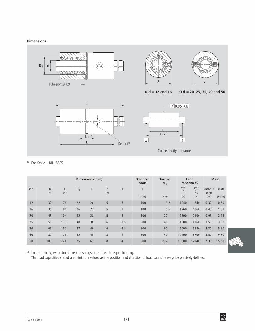
RA 83 100.1 171
Dimensions 62 B3 62 B4
Ø d = 12 and 16
Concentricity tolerance
Ø d = 20, 25, 30, 40 and 50
62 B2
62 B5 62 b 6
D D
1) For Key A... DIN 6885
2) Load capacity, when both linear bushings are subject to equal loading.The load capacities stated are minimum values as the position and direction of load cannot always be precisely defined.
Dimensions (mm) Standard Torque Load Massshaft Mt capacities2)
Ød D L D1 L1 b t I dyn. stat. without shafth6 h11 P9 C C0 shaft
(mm) (Nm) (N) (N) (kg) (kg/m)
12 32 76 22 20 5 3 400 3.2 1040 840 0.32 0.89
16 36 84 26 22 5 3 400 5.5 1260 1060 0.40 1.57
20 48 104 32 28 5 3 500 20 2500 2100 0.95 2.45
25 56 130 40 36 6 3.5 500 40 4900 4360 1.50 3.80
30 65 152 47 40 6 3.5 600 60 6000 5580 2.30 5.50
40 80 176 62 45 8 4 600 140 10200 8700 3.50 9.80
50 100 224 75 63 8 4 600 272 15000 12940 7.30 15.30
b
I
L 1
L
1)
1)
D1 d
Lube port Ø 3.9
Depth t1)
0.05
BA
L+20
AB
L

172 RA 83 100.1
STAR – Linear Sets incorporating one Torque-Resistant Compact Linear Bushing
Linear Sets, 0723-Sleeve design, flanged version
Structural design
• Flanged steel sleeve
• Torque-Resistant Compact LinearBushing
• Precision Steel Shaft with ball guidegroove
• Torque-transmitting steel load bearingplates adjusted to zero clearance beforeleaving factory
• External seals
• Stability against cocking loads:installation of two Linear Sets(see also "Retention options - LinearSets (sleeve design)")
• Lubricatable
One ball guide groove forshaft diameter d = 12 and 16 mm
Two ball guide grooves forshaft diameter d = 20 mm and over
63B1
Ordering data
Shaft Part numbersLinear Set with Torque-Resistant Compact Linear Bushing and shaft
Ø d standard shaft length shaft length shaft length shaft to customized(mm) length 900 mm 1200 mm 2000 mm specified shaft
as per table length1)
12 0723-212-80 0723-212-85 0723-212-87 0723-212-88 0723-212-89 0723-212-86
16 0723-216-80 0723-216-85 0723-216-87 0723-216-88 0723-216-89 0723-216-86
20 0723-520-80 0723-520-85 0723-520-87 0723-520-88 0723-520-89 0723-520-86
25 0723-525-80 0723-525-85 0723-525-87 0723-525-88 0723-525-89 0723-525-86
30 0723-530-80 0723-530-85 0723-530-87 0723-530-88 0723-530-89 0723-530-86
40 0723-540-80 0723-540-85 0723-540-87 0723-540-88 0723-540-89 0723-540-86
50 0723-550-80 0723-550-85 0723-550-87 0723-550-88 0723-550-89 0723-550-86
1) Also available with tubular shaft: 0723-...-69 orwith corrosion-resistant steel shaft to DIN 17230 / EN 10088: 0723-...-79.
The figures for dynamic load-carrying capacity have been calculated assuming a nominal travel of 100,000 m.For a nominal travel of 50,000 m, the 'C' figures in the table must be multiplied by a factor of 1.26.

RA 83 100.1 173
0.05 AB
BA
2L+10
L+5
2L+30
Dimensions
63 B2 63 B3 63 B4
D1 dB
30 °
D3
60 °
60 °
63 B5 63 B6 63 b 7
D 2D
L 1
L
I
S
L 2
V
D 4
Ø d = 12 and 16 Ø d = 20, 25, 30, 40 and 50
Concentricity tolerance
1) Mounting screws to ISO 4762-8.8.2) The load capacities stated are minimum values as the position and direction of load cannot always be precisely defined.
Funnel-shaped lube port D4similar to DIN 3405
Dimensions (mm) Standard Torque Load Massshaft Mt capacities2)
Ød D D4 D1 D2 L L1 L2 D3 S1) V B I dyn. stat. without shafth6 –0.1 h11 –0.2 C C0 shaft
–0.3 (mm) (Nm) (N) (N) (kg) (kg/m)
12 32 32 22 50 40 10 10 40 4.5 4.5 17.4 400 2 640 420 0.25 0.89
16 36 36 26 54 44 10 10 44 4.5 4.5 20 400 3.3 780 530 0.30 1.57
20 48 48 32 70 55 12 10 58 5.5 5 24 500 12 1550 1050 0.70 2.45
25 56 56 40 82 68 14 10 68 6.6 5.5 29 500 24 3030 2180 1.10 3.80
30 65 65 47 98 80 18 10 80 9 7 33 600 37 3680 2790 1.75 5.50
40 80 80 62 114 92 18 16 95 9 7 41.7 600 86 6320 4350 2.50 9.80
50 100 100 75 140 114 22 16 118 11 8.5 50.5 600 167 9250 6470 4.85 15.30

174 RA 83 100.1
STAR – Linear Bushings for Combined Linear and Rotary Motion
with series 60 deep groove ballbearings
28 o 1br
Ordering data
with series 618 deep groove ballbearings (sizes 12 to 40)
Linear Bushings for Combined Linear and Rotary Motion, 0663-with deep groove ball bearings, series 618
Linear Bushings for Combined Linear and Rotary Motion, 0664-with deep groove ball bearings, series 60
Structural Design
• Maintenance-free and sealed with shields (series 60)
Sizes 12 to 40
• Segmental Linear Bushing• Steel sleeve• External wiper seals• Pressed-on deep groove ball bearings
Sizes 5, 8, 50, 60 and 80
• Standard Linear Bushing• Internal wiper seals• Pressed-on deep groove ball bearings
Shaft Part numbers MassØ d with series 60 deep groove ball bearings
(mm) (kg)
5 0664-205-00 0.03
8 0664-208-00 0.11
12 0664-212-00 0.14
16 0664-216-00 0.20
20 0664-220-00 0.27
25 0664-225-00 0.32
30 0664-230-00 0.56
40 0664-240-00 0.87
50 0664-250-00 1.78
60 0664-260-00 3.26
Shaft Part numbers Mass Ø d with series 618 deep groove ball bearings(mm) (kg)
5 0663-205-00 0.02
8 0663-208-00 0.06
12 0663-212-00 0.08
16 0663-216-00 0.11
20 0663-220-00 0.15
25 0663-225-00 0.17
30 0663-230-00 0.35
40 0663-240-00 0.49
50 0663-250-00 1.29
60 0663-260-00 2.39
80 0663-280-00 5.35
(Sizes 5, 8, 50, 60 and 80)

RA 83 100.1 175
Dimensions
28 o 2
A
D1
B
d D
Dimensions (mm)Load
capacities3) (N)dyn. stat.
Ø d D D1 A B C C0
5 28 121) 8 22 180 140
82) 42 20 12 25 320 240
12 47 25 12 30 480 420
16 55 30 13 34 720 620
20 62 35 14 38 1020 870
25 68 40 15 45 1630 1360
30 80 50 16 54 2390 1960
40 95 60 18 66 3870 3270
50 115 751) 20 100 8260 6470
60 140 901) 24 125 11500 9160
1) Oversize2) A spacer sleeve is located between the ball bearing and the
Standard Linear Bushing.3) The figures given for load capacity are minimum values as the
position and load direction cannot be precisely defined.
Series 0663 und 0664: Shaft: dh6
Housing bore DK6 or DK7
Other tolerance zones may be selected for special purposes(refer to the anti-friction bearing manufacturer’s mounting recommendations).
Sealing:
Recommended tolerances
The linear bushings are sealed at both ends.
Series 0663: If the deep groove ball bearings are to be sealed with shaftseals, please send for Table 06/060-00.
Series 0664: In all sizes the deep groove ball bearings are maintenance-freewith shields at both ends.
A
D1
B
d D
28 o 4
with series 60 deep groove ball bearings
The figures for dynamic load-carrying capacity have been calcu-lated assuming a nominal travel of 100,000 m.For a nominal travel of 50,000 m, the 'C' figures in the tablesopposite must be multiplied by a factor of 1.26.
with series 618 deep groove ball bearingsDimensions (mm)
Loadcapacities3) (N)dyn. stat.
Ø d D D1 A B C C0
5 21 121) 5 22 180 140
82) 32 20 7 25 320 240
12 37 25 7 30 480 420
16 42 30 7 34 720 620
20 47 35 7 38 1020 870
25 52 40 7 45 1630 1360
30 65 50 7 54 2390 1960
40 78 60 10 66 3870 3270
50 95 751) 10 100 8260 6470
60 115 901) 13 125 11500 9160
80 150 1201) 16 165 21000 16300

176 RA 83 100.1
STAR – Linear Bushings for Combined Linear andRotary Motion
Structural Design
• Standard Linear Bushing(closed type)
• Needle roller bearings
• Steel spacer rings
• Retaining rings
2901
Ordering data
Shaft Part numbers MassØ d with two without (kg)
(mm) seals seals
5 0667-005-00 0665-005-00 0.02
8 0667-008-00 0665-008-00 0.04
12 0667-012-00 0665-012-00 0.08
16 0667-016-00 0665-016-00 0.10
20 0667-020-00 0665-020-00 0.20
25 0667-025-00 0665-025-00 0.34
30 0667-030-00 0665-030-00 0.56
40 0667-040-00 0665-040-00 1.39
50 0667-050-00 0665-050-00 2.18
60 0667-060-00 0665-060-00 4.14
80 0667-080-00 0665-080-00 7.11
with needle roller bearings
Linear Bushings for Combined Linear and Rotary Motion, 0665-with needle roller bearings, without wiper seal
Linear Bushings for Combined Linear and Rotary Motion, 0667-with needle roller bearings, with wiper seal
The figures for dynamic load-carrying capacity have been calculated assuming a nominal travel of 100,000 m.For a nominal travel of 50,000 m, the 'C' figures in the tables must be multiplied by a factor of 1.26.

RA 83 100.1 177
Dimensions
29 o 2
Dimensions (mm) Load capacities4) (N)
dyn. stat.
Ø d D1 B D b A C C0
51) 12 22 19 12 12 180 140
81) 16 25 24 13 14.1 320 240
12 22 32 30 16 20 420 280
16 26 36 34 20 22.1 580 440
20 32 45 42 20 28 1170 860
25 40 58 50 30 40 2080 1560
30 47 68 57 30 48 2820 2230
402) 62.13) 80 80 56 56 5170 3810
502) 75 100 92 70 73.1 8260 6470
602) 90 125 110 70 95 11500 9160
802) 120 165 140 81.6 125 21000 16300
1) With plastic ball retainer.2) Contrary to the illustration, these sizes have two needle roller bearings.3) The basic body is a special version of the closed Standard Linear Bushing.4) The figures given for load capacity are minimum values as the position and load direction cannot be precisely defined.
Dd
B
D1
b
A
Recommended tolerances: Shaft dh6
Housing bore DK6 or DK7
Other tolerance zones may be selected for special purposes(refer to the anti-friction bearing manufacturer’s mounting recommendations).

178 RA 83 100.1
STAR Precision Steel Shafts come in various tolerance grades, as solid or tubular shafts,in heat-treatable or corrosion-resistant steel, with hard chrome plating or STAR-Resistcoating, and in metric or inch sizes.
They are induction hardened and centerless ground.
Besides their use as guide shafts for linear bushings, STAR Precision Steel Shafts haveproven successful in numerous other applications, for example as rollers, pistons or axles.
We supply STAR Precision Steel Shafts to your requirements: cut to length and chamferedat both ends, machined to your drawing or description, or in unmachined mill-cut lengths.
For shipment, STAR Precision Steel Shafts are coated with an anti-corrosion film andpacked in wooden crates, cardboard boxes, railroad containers, etc., according to the sizeand quantity involved.
You can rely on competent advice and rapid service from the headquarters and regionalsales offices in Germany as well as subsidiaries and agencies in over 60 countries allaround the world.
STAR Precision Steel Shafts offer you the right solution for any requirement.
STAR – Precision Steel Shafts

RA 83 100.1 179
56o1

180 RA 83 100.1
STAR – Precision Steel Shafts
Shaft Part numbersSolid shafts
Ø d Heat-treatable steel X46Cr13 X90CrMoV18(mm) h6 h7 h6 h7 h6 h7
5 1000-005-00 1000-005-01 1000-005-30 1000-005-31
6 1000-006-00 1000-006-01 1000-006-30 1000-006-31
8 1000-008-00 1000-008-01 1000-008-30 1000-008-31
10 1000-010-00 1000-010-01 1000-010-30 1000-010-31
12 1000-012-00 1000-012-01 1000-012-30 1000-012-31 1000-012-20 1000-012-21
14 1000-014-00 1000-014-01
15 1000-015-00 1000-015-01
16 1000-016-00 1000-016-01 1000-016-30 1000-016-31 1000-016-20 1000-016-21
18 1000-018-00 1000-018-01
19 1000-019-00 1000-019-01
20 1000-020-00 1000-020-01 1000-020-30 1000-020-31 1000-020-20 1000-020-21
22 1000-022-00 1000-022-01
24 1000-024-00 1000-024-01
25 1000-025-00 1000-025-01 1000-025-30 1000-025-31 1000-025-20 1000-025-21
30 1000-030-00 1000-030-01 1000-030-30 1000-030-31 1000-030-20 1000-030-21
32 1000-032-00 1000-032-01
35 1000-035-00 1000-035-01
38 1000-038-00 1000-038-01
40 1000-040-00 1000-040-01 1000-040-30 1000-040-31 1000-040-20 1000-040-21
45 1000-045-00 1000-045-01
50 1000-050-00 1000-050-01 1000-050-30 1000-050-31 1000-050-20 1000-050-21
55 1000-055-00 1000-055-01
60 1000-060-00 1000-060-01 1000-060-30 1000-060-31 1000-060-20 1000-060-21
70 1000-070-00 1000-070-01
80 1000-080-00 1000-080-01 1000-080-30 1000-080-31 1000-080-20 1000-080-21
100 1000-100-00 1000-100-01
110 1000-110-00 1000-110-01
Shaft Part numbersSolid shafts
Ø d Heat-treatable steel X90CrMoV18(inch) Class "L" Class "S" Class "L" Class "S"
1/4" 1000-804-08 1000-804-09
3/8" 1000-806-08 1000-806-09
1/2" 1000-808-08 1000-808-09 1000-808-28 1000-808-29
5/8" 1000-810-08 1000-810-09
3/4" 1000-812-08 1000-812-09 1000-812-28 1000-812-29
1" 1000-816-08 1000-816-09 1000-816-28 1000-816-29
1 1/4" 1000-820-08 1000-820-09
1 1/2" 1000-824-08 1000-824-09 1000-824-28 1000-824-29
2" 1000-832-08 1000-832-09
Metric sizes
Inch sizes
Overview

RA 83 100.1 181
Shaft Part numbers
Solid shaft Tubular shaft
Ø d Star Resist hard chrome plated heat-treatable steel hard chrome plated(mm) h6 h6 h7 h6 h7 h7
5 1000-005-70
6
8 1000-008-70
10 1000-010-70
12 1000-012-70 1000-012-60 1000-012-61
14
15
16 1000-016-70 1000-016-60 1000-016-61
18
19
20 1000-020-70 1000-020-60 1000-020-61
22
24
25 1000-025-70 1000-025-60 1000-025-61 1001-025-10 1001-025-11 1001-025-41
30 1000-030-70 1000-030-60 1000-030-61 1001-030-10 1001-030-11 1001-030-41
32
35
38
40 1000-040-70 1000-040-60 1000-040-61 1001-040-10 1001-040-11 1001-040-41
45
50 1000-050-70 1000-050-60 1000-050-61 1001-050-10 1001-050-11 1001-050-41
55
60 1000-060-60 1000-060-61 1001-060-10 1001-060-11 1001-060-41
70
80 1000-080-60 1000-080-61 1001-080-10 1001-080-11 1001-080-41
100 1001-100-10 1001-100-11
110

182 RA 83 100.1
STAR – Precision Steel ShaftsTechnical Data
Dimensional accuracy andtolerance zonesThe diameters of Precision Steel Shafts areaccurate to within the tolerance zones h6and h7. Details on the dimensional accu-racy of the shafts are compiled in the tableson the right. The tolerance for the diameterof soft-annealed shaft sections may goslightly beyond the tolerance zones quoted.
On request, Precision Steel Shafts may alsobe supplied in tolerance zone h5 (standarddiameters 30 to 80 only).
For special diameter tolerances, pleaseconsult us.
Straightness
Because of the length of the shafts, itwould be uneconomical to use thestraightness measurement methodspecified in DIN ISO 1101 section 14.1.Instead of direct measurement for straight-ness, the shafts are tested for runouttolerance as described in DIN ISO 1101section 14.13.1.See "Measurement of straightness".
Tolerances for metric-size steel shafts
Nominal diameter (mm) over 3 6 10 18 30 50 80
up to 6 10 18 30 50 80 1200 0 0 0 0 0 0
Tolerance h6 (µm) –8 –9 –11 –13 –16 –19 –22for diameter 0 0 0 0 0 0 0
h7 (µm) –12 –15 –18 –21 –25 –30 –35
Roundness h6 (µm) 4 4 5 6 7 8 10h7 (µm) 5 6 8 9 11 13 15
Taper, h6 (µm) 5 6 8 9 11 13 15Convexity, h7 (µm) 8 9 11 13 16 19 22Concavity
Straightness (µm/m) 75 60 50 50 50 50 50
Measured value t11) (µm/m) 150 120 100 100 100 100 100
Surface roughness C.L.A.(Ra)2) (µm) 0.32 0.32 0.32 0.32 0.32 0.32 0.32
3) Class "S" by special request only.
1) Dial gauge reading during straightness measurement. For lengths of less than 1 m thelowest possible value is 40 µm. This corresponds to a straightness tolerance of 20 µm.
2) Applies to shafts made of heat-treatable or anti-friction bearing steel only.Please contact us for surface finish and surface roughness (Ra) tolerances for hardchrome plated and corrosion-resistant steel shafts.
Tolerances for inch-size steel shafts
Shaft Ø d Class "L" Class "S"3)
(Inch) (mm) (Inch) (mm) (Inch) (mm)
1/4 6.35 –0.0005 –0.013 –0.0010 –0.025–0.0010 –0.025 –0.0015 –0.038
3/8 9.525 –0.0005 –0.013 –0.0010 –0.025–0.0010 –0.025 –0.0015 –0.038
1/2 12.70 –0.0005 –0.013 –0.0010 –0.025–0.0010 –0.025 –0.0015 –0.038
5/8 15.875 –0.0005 –0.013 –0.0010 –0.025–0.0010 –0.025 –0.0015 –0.038
3/4 19.05 –0.0005 –0.013 –0.0010 –0.025–0.0010 –0.025 –0.0015 –0.038
1 25.40 –0.0005 –0.013 –0.0010 –0.025–0.0010 –0.025 –0.0015 –0.038
11/4 31.75 –0.0005 –0.013 –0.0010 –0.025–0.0010 –0.025 –0.0015 –0.038
11/2 38.1 –0.0006 –0.015 –0.0011 –0.028–0.0011 –0.028 –0.0016 –0.041
2 50.8 –0.0006 –0.015 –0.0013 –0.033–0.0013 –0.033 –0.0020 –0.051

RA 83 100.1 183
112/458 MADE IN ENGLAND
THE RANK ORGANISATION, RANK TAYLOR HOBSON DIVISION
SPECIMEN
TALYRONDµ
MAGN FILTER
2000
No. 1/3
N
112/458 MADE IN ENGLAND
THE RANK ORGANISATION, RANK TAYLOR HOBSON DIVISION
SPECIMEN
TALYRONDµ
MAG N FILTER
1000
No. 1/3
N
58o2 58o3
58 0 1
Raw shaft Precision Steel Shaft
58o4a58o4b
Measurement of straightness
Measurements are performed at pointsequidistant between the support pointsand the overhanging ends of the shaft. Themeasured values are then halved and theresulting value t1 gives the straightness.
Measurement of roundness
The figure shows the roundness of a rawshaft compared with that of a finishedPrecision Steel Shaft.
Shaft hardnessThe surface of the shaft is induction-hardened to a depth of at least 0.4 up to3.2 mm, depending on the shaft diameter.Surface hardness and depth of hardnessare extremely uniform, both in the axialand in the circumferential direction. This isthe reason for the excellent dimensionalconsistency and the long service life ofPrecision Steel Shafts.The photographs opposite show a longitu-dinal and a transverse section through ahardened and ground Precision Steel Shaft.The hardened surface zone has been madevisible by caustic etching.
Shaft Ø d (mm) over 3 10 18 30 50 80up to 10 18 30 50 80 120
Depth of hardness1) (mm) min. 0.4 0.6 0.9 1.5 2.2 3.2
1) Please contact us to obtain the depth of hardness for corrosion-resistantsteel shafts.
A B
A B
A B A B
0 . 3 LL
0 . 4 L 0 . 3 L
t1 t1 t1

184 RA 83 100.1
STAR – Precision Steel ShaftsTechnical Data
59o1
62 0 2
62 0 1
62 0 3
62 0 4
62 0 5
a b aF F
x
l
fm1
f1
α
a b a
x
F F
fm2
f2
BA lα
b aF
x
l
fm3
f3
α
b a
x
F
fm4
f4
BA lα
x fm5
BA l
α
Minimum hardness
Solid and tubular shafts → HRC 60
Corrosion-resistantsteel shafts → HRC 53to DIN 17230 / EN 10088
The figure opposite shows the micro-structure in the surface zone of a shaftcross section (magnification approx. 10x).The hardened outer layer of martensite andthe smooth transition to the tough innercore structure are clearly visible.
Induction-hardened surface zoneStructure: martensitehardness ≥ HRC 60 (Rockwell C)
Transitional structure:martensitetroostitepearlite
Core structure:pearlite and ferrite
Shaft deflection When steel shafts are used as linear motion guideways for linear bushings it is importantthat the shaft deflection occurring under load is kept within certain limits, as otherwise theproper functioning and the service life of the assembly could be impaired1).To facilitate the determination of shaft deflection by calculation, we have compiled themost common load cases together with the associated deflection equations in the tablebelow.The equations for calculation of the inclination of the shaft in the linear bushing (tan α)can also be taken from this table.
1) There will be no loss of load-carrying capacity or service life in Super Linear Bushings , and provided the shaft deflection doesnot exceed 30’ (tan 30’ = 0.0087).
Case Loading conditions Deflection equation Shaft inclinationNo. in linear bushings
1
2
3
4
5
f1 = · (2 – )F · a3
6 · E · J3 · a
I
fm1 = · (3I – 4a)F · a2
24 · E · J
f2 = · · (1 – · )F · I3
2 · E · J4
3
a2
I2a
I
fm2 = · · (1 – · )F · I3
8 · E · J4
3
a
I
a2
I2
f3 = ·F · I3
3 · E · J
a3 · b3
I3 · I3
fm3 = · · ·( )22 ·F · I3
3 · E · J
I
I + 2aa3
I3b2
I2
f4 = ·F · I3
3 · E · J
a2 · b2
I2 · I2
fm4 = f4 · ·I + b
3 · b
I + b
3 · a
f5 =5 · F · I3
384 · E · J
tan α(x=a) =F · a2 · b
2 · E · J · I
tan α(x=a) =F · a · b
2 · E · J
tan α(x=0) =F · I2
24 · E · J
tan α (x=b) = ·(3b2 – I2 + a2)F · a
6 · E · J · I
tan α(x=b) = ·(1 – )F · a2 · b2
2 · E · J · I22 · b
I

RA 83 100.1 185
The table gives the values for the maximumpermissible shaft inclination (tan αmax) foreach size of Standard Linear Bushing.At tan α = tan αmax the permissible staticload capacity is approx. 0.4 CO.
Shaft
Ø d tan αmax(mm)
5 12.3 · 10–4
8 10.0 · 10–4
12 10.1 · 10–4
16 8.5 · 10–4
20 8.5 · 10–4
25 7.2 · 10–4
Shaft
Ø d tan αmax(mm)
30 6.4 · 10–4
40 7.3 · 10–4
50 6.3 · 10–4
60 5.7 · 10–4
80 5.7 · 10–4
Tubular shaftsØ d E x J Mass
outer Ø inner Ø
(mm) (mm) (N x mm2) (kg/m)
25 14 3.63 · 109 2.63
30 19 7.01 · 109 3.30
40 26.5 2.13 · 1010 5.50
50 29.6 5.65 · 1010 9.95
60 36.5 1.15 · 1011 13.89
80 57.4 3.10 · 1011 19.02
Values for E x J and mass for steel shafts
Solid shaftsØ d E x J Mass Ø d E x J Mass
(mm) (N x mm2) (kg/m) (Inches) (mm) (N x mm2) (kg/m)
5 6.44 · 106 0.15 1/4 6.35 1.68 · 107 0.25
8 4.22 · 107 0.39 3/8 9.525 8.48 · 107 0.56
10 1.03 · 108 0.61 1/2 12.7 2.68 · 108 0.99
12 2.14 · 108 0.88 5/8 15.875 6.55 · 108 1.54
16 6.76 · 108 1.57 3/4 19.05 1.36 · 109 2.22
20 1.65 · 109 2.45 1 25.4 4.29 · 109 3.95
25 4.03 · 109 3.83 1 1/4 31.75 1.05 · 1010 6.18
30 8.35 · 109 5.51 1 1/2 38.1 2.17 · 1010 8.89
40 2.64 · 1010 9.80 2 50.8 6.87 · 1010 15.81
50 6.44 · 1010 15.32
60 1.34 · 1011 22.05
80 4.22 · 1011 39.21

186 RA 83 100.1
Mill-cut lengthsLonger shafts than those quoted can alsobe supplied on request. These shafts aremade up of shaft sections of preciselymeasured length joined end-to-end (seesection on "Composite shafts" below).
Type of shaft Diameter (mm) Mill-cut length1) (m)
Solid shafts2) < 20 (except 12 and 16) 3.5 up to 4.012, 16 and ≥ 20 5.7 up to 5.9
Tubular shafts 25 up to 100 4 up to 5.93)
Corrosion-resistant 5 up to 20 3.5 up to 4.0steel shafts > 20 up to 80 5.7 up to 5.9
We can supply composite shafts for applications requiring a shaft longer than the mill-cutlengths available. The shaft sections are joined together by a spigot-and-recess arrange-ment, one section having a locating plug and the other a mating hole (see figure below).The joined shaft must rest on a full-length, continuous support rail or must at least besupported at regular intervals with one of the supports located at the joint between theshaft sections (see "Shaft Support Rails").
1) The first 50 mm at each end of mill-cut lengths may deviate slightly from the nominaldiameter.
2) Solid shafts of lengths up to 8 m and diameter 20 and over are available on request.3) Depending on size.
Composite shaftsPlug-and-socket joints
STAR – Precision Steel ShaftsDiameters and Lengths
At the customer’s request, the plug can be threaded and the mating hole tapped (seefigure below). Line-up markings are then provided at the ends of the mating shaft sectionsto facilitate vertical alignment of the radial holes for attachment of the coupled shaftassembly to the shaft support rail.All machining and marking operations are carried out on the shaft sections after they havebeen hardened and ground. Since it will not be possible to re-grind the finished joint,extreme care is taken in the machining of the centering arrangement to ensure precisionmating of the shaft sections.
Shafts with threaded joints(does not apply to corrosion-resistant steel shafts)
Line-up markings here
The shafts must be axially tensioned against each other at the time the shaft assembly isscrewed to the shaft support rail. This is to prevent a gap opening at the joint when theshaft assembly is loaded in service.

RA 83 100.1 187
59 0 2
20°
L 1
d
Dimensions in mm
Length Tolerance
up to 400 ±0.5
over 400 ±0.8up to 1000
over 1000 ±1.2up to 2000
over 2000 ±2.0up to 4000
over 4000 ±3.0up to 6000
over 6000 ±3.5up to 8000
Shaft MachiningSteel shafts intended for use as linearmotion guideways for Linear Bushingsmust be chamfered at the ends to pre-vent damage to the ball retainers orwipers when the linear bushing is beingpushed onto the shaft.The figure and the table give thedimensions of the chamfers required.Linear bushings with seals must not bepushed over sharp edges in the shaft(e.g. retaining ring grooves), as thiswould damage the seal lips.
Shaft Ø d (mm) 5 8 10 12 16 20 25 30 40 50 60 80
Length ofchamfer L1 (mm) 1.5 1.5 1.5 2 2 2 2 2 3 3 3 3
Hardened and ground steel shafts in mill-cut lengths are always in stock. These can be cutto any desired length and machined to give them any of the following:
• reduced-diameter ends • radial or axial holes
• male or female threads • recesses
• countersinks • or other specially-machined features.
Length tolerances forcut-to-size shafts
Steel shafts with closer length tolerances can also be supplied against a surcharge.

188 RA 83 100.1
Standard shaft ends
WU 2
d h6
/h7=
L 0 =
L 1 =
L =
L 2 =WU 1
d h6
/h7=
L 0 =
L 1 =
L =
L 2 =
STAR – Precision Steel ShaftsShaft Machining
Shaft ends with 90° cutout
Machining of shaft ends has been standardized at STAR.
The expertise acquired over the years in special shaft machining techniques offers you thefollowing benefits:
– rapid processing,
– lower costs.
If you would like your shafts machined to any of the examples given below, we recommendthat you
• copy the drawing,
• enter the dimensions and tolerances, and
• indicate whether you would like only one or both shaft ends to be so machined.
When selecting tolerances, please avoid any overdetermination.
Attach the annotated drawing to your order.
Shaft ends with retaining ring grooveto DIN 471

RA 83 100.1 189
WU 3
WU 5
d h6
/h7=
L =
B =
t =
t =
B =
WU 6d
h6/h
7=
L =
B =
B =
t =t =
SW
=d
h6/h
7=
L 0 = L 1 =
L =
L 2 =
Shaft ends with 90° countersink
Shaft ends with single flat(both ends)
Shaft ends with outer flats(one end)

190 RA 83 100.1
d h6/h7=
L =
t3 =
t4 =
d1
=
dt=
X X
WU 7
WU 8
d h6
/h7=
B =L 4 =
t =
t =
L 5 =
B = L 4 =
L 5 =
L =
L 5 =
d h6
/h7=
B =L 4 =t
=t
=L 5 =
B =L 4 =
L =
SW =
WU 12
STAR – Precision Steel ShaftsShaft MachiningShaft ends with grooves (both ends)
Shaft ends with inner flats (one end)
Shaft ends with holes tapped to pitchcircle (both ends)
Core holeø to DIN 336or DIN 13
View X

RA 83 100.1 191
WU 13
WU 14
Shaft ends with spigot (both ends)
WU 11
Shaft ends with threaded spigot(both ends)
Shaft ends with spigot and threadedspigot (both ends)
WU 10
WU 9
d h6/h7=
L 1 =
L =
L 2 =L 2 =
d1 =
d1 =
α=α=
or undercuttype F DIN 509(both ends)
Thread runout to DIN 76-a1(DIN 76-A for undercut)
We recommendDIN 76-A for undercut
We recommend type F DIN 509for undercut
We recommend type DIN 76-Afor undercut
Thread runoutto DIN 76-a1
d h6/h7=
L 1 =
L =
L 7 =L 7 =
d1 =
d 2 =
R 0.4 +0.4
L 8 =
L 2 =
L 8 =
L 2 =
d h6/h7=
L 1 =
L =
L 2 =L 2 =
d1 =
d1 =
R 0.4 +0.4

192 RA 83 100.1
STAR – Precision Steel ShaftsShaft Machining
WU 4
Shaft ends with tapped hole andcentering bore to DIN 332-D
ø to DIN 336or DIN 13
L =
d =
t2=
t1= t
1=
t2=
d =
d 1=
d 1=
For a tapped hole with centering bore,we recommend DIN 332-D
L =
t3=
t4= t4=
t3=
d1= d1=
Shaft ends with tapped hole

RA 83 100.1 193
Shafts with radial holes, drilled ordrilled and tapped
Shafts that have to be supported requireradial holes for attachment of the shaftsupports. The radial holes are drilled intothe steel shafts after hardening andgrinding.The diameter, depth and spacing of theholes depend on the diameter of the shaft.Refer to the table in the sections "ShaftSupport Rails for Standard and Super LinearBushings" and "Shaft Support Rails forRadial Linear Bushings" for standarddimensions.
d h6
/h7=
x =
L =
y =n x T =
t 2
N =
d1 =
T =
d2 =d1 + approx.1mm
Shaft Dimensions (mm)Ø d
(mm) d1 t2
12 M4 2.5
16 M5 2.5
20 M6 3.0
25 M8 3.0
30 M10 3.5
40 M10 4.0
40 M12 4.5
Shaft Dimensions (mm)Ø d
(mm) d1 t2
50 M12 4.0
50 M14 4.5
50 M16 5.0
60 M14 5.5
60 M20 6.5
80 M16 5.5
80 M24 6.5
For matching Shaft Support Rails,see the related chapter.
Steel Shafts can also be deliveredwith ready-mounted Shaft SupportRails as standard.
Values for corrosion-resistant steel shafts on request
Recommended values for boringof clearing holes in the hardenedsurface zone

194 RA 83 100.1
STAR – Precision Steel ShaftsOrdering Data
When a shaft forms an integral part of an anti-friction bearing system, the materials usedhave to satisfy exacting requirements.STAR offers the optimum shaft material for each diameter range. The materials we usehave a much higher carbon content compared to frequently used mass-produced steels,which has a very positive influence on the achievable surface hardness and provides betterresistance to aging.The exceptionally uniform surface hardness and hardening depth of STAR shafts, com-bined with an excellent degree of purity, homogeneous microstructure and defined grainsizes, ensure particularly long service life under rolling loads.
Materials Hardness
Cf 53, Cf 60, Ck 67 min. 60 HRC
Ø d (mm) Lengths (m)
5-10, 14, 15, 18 approx. 3.5 to 4.0
12, 16, 20-110 approx. 5.7 to 5.9Solid shafts from 20 mm in diameter and up to 8 m in length on request.Greater overall lengths are composed of sections joined end-to-end.STAR Linear Bushings can roll over joints without any problems.
Part numbers
Tolerance h6 1000-xxx-00
Tolerance h7 1000-xxx-01xxx = diameter in mm
Ordering example:For a solid shaft of heat-treatable steel,25 mm diameter, 460 mm length,tolerance quality h7Part No. 1000-025-01, 460 mm
Available diameters (mm)
5, 6, 8, 10, 12, 14, 15, 16, 18, 20, 22, 24, 25, 30, 32, 35, 38, 40, 45, 50, 55, 60,70, 80, 100, 110
Solid shafts made of heat-treatable steel, metric sizes
Ordering example: For a solid shaft of corrosion-resistant steel X 46 Cr 13, 16 mmdiameter, 350 mm length, tolerance quality h6Part No. 1000-016-30, 350 mm
Solid shafts made ofcorrosion-resistant steel
to DIN 17230 / EN 10088
Ø d (mm) Lengths (m)
5-20 approx. 3.5 to 4.0
25-80 approx. 5.7 to 5.9
Greater overall lengths are composed of sections joined end-to-end.STAR Linear Bushings can roll over joints without any problems.
Materials Hardness
X 46 Cr 13 min. 54 HRC
X 90 CrMoV 18 min. 55 HRC
Materials Available diameters (mm)
X 46 Cr 13 5, 6, 8, 10, 12, 16, 20, 25, 30, 40, 50, 60, 80
X 90 CrMoV 18 12, 16, 20, 25, 30, 40, 50, 60, 80
The correct choice for applications requiring high corrosion resistance in a clean environ-ment, e.g. in the food industry, semiconductor manufacture and medical engineering.X 90 CrMoV 18 differs from X 46 Cr 13 in that it is additionally resistant to lactic acid.
Part numbers
X 46 Cr 13 X 90 CrMoV 18
Tolerance h6 1000-0xx-30 Tolerance h6 1000-0xx-20
Tolerance h7 1000-0xx-31 Tolerance h7 1000-0xx-21xx = diameter in mm

RA 83 100.1 195
STAR-Resist provides inexpensive cathodic anti-corrosion protection for the steel basematerial through a zinc-iron coating with yellow chromating. The initial layer thickness ofapprox. 5 µm is compacted by rolling loads in the travel zone during the running-in cycles,thus canceling out the oversize. Cathodic action continues to protect the shaft fromrusting even when the coating is slightly damaged.Suitable for providing reliable anti-corrosion protection in applications involving a highlevel of humidity, changing climatic conditions with condensation, hand perspiration, orsimilar influences.Not suitable for contact with food.
Solid shafts,with STAR-Resist coating
The length of STAR-Resist-coated shafts is limited to around 3.5 m.Greater overall lengths are composed of sections joined end-to-end. STAR Linear Bushingscan roll over joints without any problems.
Available diameters (mm)
5, 8, 10, 12, 16, 20, 25, 30, 40, 50
Materials Hardness
Cf 53, Cf 60, Ck 67 min. 60 HRC
Part numbers
Tolerance h6 1000-0xx-70
Tolerance h7 1000-0xx-71xx = diameter in mm
Ordering example:For a solid shaft, STAR-Resist-coated, 20 mm diameter, 450 mm length, tolerance quality h7Part No. 1000-020-71, 450 mm
Materials Hardness
Cf 53, Cf 60, Ck 67 min. 60 HRC (approx. 700 HV)
Chrome plating (thickness approx. 10 µm) approx. 1000 HV
Ø d (mm) Lengths (m)
12-20 approx. 3.5 to 4.0
25-80 approx. 5.7 to 5.9
Greater overall lengths are composed of sections joined end-to-end. STAR Linear Bushingscan roll over joints without any problems.
Part numbers
Tolerance h6 1000-0xx-60
Tolerance h7 1000-0xx-61
xx = diameter in mm
Ordering example:For a solid shaft, hard chrome plated, 30 mmdiameter, 480 mm length, tolerance quality h7Part No. 1000-030-61, 480 mm
Available diameters (mm)
12, 16, 20, 25, 30, 40, 50, 60, 80
Optimum anti-corrosion protection for applications in chemically aggressive environments,or for particularly attractive visual effect.
Solid shafts,hard chrome plated
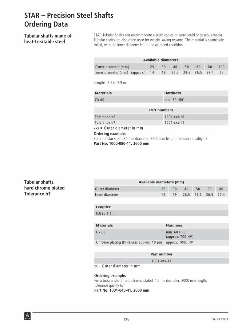
196 RA 83 100.1
STAR – Precision Steel ShaftsOrdering DataTubular shafts made ofheat-treatable steel
Available diameters
Outer diameter (mm) 25 30 40 50 60 80 100
Inner diameter (mm) (approx.) 14 19 26.5 29.6 36.5 57.4 65
Materials Hardness
Ck 60 min. 60 HRC
STAR Tubular Shafts can accommodate electric cables or carry liquid or gaseous media.Tubular shafts are also often used for weight-saving reasons. The material is seamlesslyrolled, with the inner diameter left in the as-rolled condition.
Lengths: 5.5 to 5.9 m
Part numbers
Tolerance h6 1001-xxx-10
Tolerance h7 1001-xxx-11
xxx = Outer diameter in mmOrdering example:For a tubular shaft, 80 mm diameter, 3600 mm length, tolerance quality h7Part No. 1000-080-11, 3600 mm
Tubular shafts,hard chrome platedTolerance h7
Materials Hardness
Ck 60 min. 60 HRC(approx. 700 HV)
Chrome plating (thickness approx. 10 µm) approx. 1000 HV
Available diameters (mm)
Outer diameter 25 30 40 50 60 80
Inner diameter 14 19 26.5 29.6 36.5 57.4
Part number
1001-0xx-41xx = Outer diameter in mm
Ordering example:For a tubular shaft, hard chrome plated, 40 mm diameter, 2000 mm length,tolerance quality h7Part No. 1001-040-41, 2000 mm
Lengths:
5.5 to 5.9 m

RA 83 100.1 197
Solid shafts made of heat-treatable steel, inch sizes
Ø d (inch) Lengths (m)1/4 –
3/4 approx. 3.5 to 4.0
1 – 2 approx. 5.7 to 5.9
Greater overall lengths are composed of sections joined end-to-end. STAR Linear Bushingscan roll over joints without any problems.
Materials Hardness
Cf 53, Cf 60, Ck 67 min. 60 HRC
Part numbers
Class "L" 1000-8xx-08
Class "S" 1000-8xx-09
xx: see table
Available diameters
Ø (inch) 1/43/8
1/25/8
3/4 1 11/4 11/2 2
xx 04 06 08 10 12 16 20 24 32
Ordering example:For a solid shaft of heat-treatable steel, 1/2 inch diameter, 800 mm length, class "S"Part No. 1000-808-09, 800 mm
Solid shafts of corrosion-resistant steelto DIN 17230 / EN 10088,inch sizes
Ø d (inch) Lengths (m)
1/2 - 3/4 approx. 3.5 to 4.0
1 - 11/2 approx. 5.7 to 5.9
Greater overall lengths are composed of sections joined end-to-end. STAR Linear Bushingscan roll over joints without any problems.
Materials Hardness
X 90 CrMoV 18 (resistant to lactic acid) min. 55 HRC
Part numbers
Class "L" 1000-8xx-28
Class "S" (on request) 1000-8xx-29
xx: see table
Ordering example:For a solid shaft of corrosion-resistant steel X 90 CrMoV 18, 1 inch diameter,2500 mm length, class "L"Part No. 1000-816-28, 2500 mm
Available diameters
Ø (inch) 1/23/4 1 11/2
xx 08 12 16 24

198 RA 83 100.1
STAR – Shaft Support Rails
Shaft Support Rails are designed to support the shafts on which open-type LinearBushings run to prevent them from bending under load.Shaft Support Rails are delivered in ready-to-mount sections of high dimensionalaccuracy and are specially designed to give high rigidity. Their low overall heightallows the construction of extra-compact linear motion assemblies.
AdvantagesShaft Support Rails
• prevent shaft deflection
• ensure efficient running of linear motion assemblies
• eliminate the need for users’ own time-consuming and costly designs.
Shaft Support Rails are specially engineered sections manufactured mainly in standardlengths of 600 mm or 3000 mm. They can be mounted end to end for continuous shaftsupport or cut to any desired length for spaced support.
Ten different shaft support rails are available for shaft diameters from 12 to 80 mm.Intermediate shaft sizes can be mounted on the shaft support rail nearest in size tothe shaft diameter. If in doubt, the next larger support rail should be used.
Shaft Support Rails are also (and in some cases exclusively)
available with ready-mounted Precision Steel Shafts.

RA 83 100.1 199
37b1a

200 RA 83 100.1
yX T
yX T
X T y1054-1 1054-2
STAR – Shaft Support Rails with ready-mounted steel shafts
1. General STAR can supply steel shafts ready-mounted on seven different types of shaft support rails.The individual support rails are arranged end to end underneath the corresponding shafts.Once the elements have been aligned and the linear motion assemblies screwed downonto a torsionally stiff, surface-machined base, the units will reflect the tolerances asgiven in the tables.
2. Part numbers 2.1 For use with open-type Standard and Super Linear Bushings
Type 1014 = Steel shaft with flangedaluminum shaft support rail, low-profileversion1050-6..-..1050-7..-..
Type 1015 = Steel shaft with aluminumshaft support rail, for side mounting1054-1..-..1054-2..-..
Type 1011 = Steel shaft with flangedaluminum shaft support rail, high-profileversion1050-1..-..1050-2..-..
yX T
Type 1010 = Steel shaft with flangedaluminum shaft support rail, low-profileversion, greater height tolerance, cost-effective(only available ready-mounted)
yX T
Type 1025 = Steel shaft with aluminumshaft support rail, for ALU-STAR ProfileSystems, low-profile version

RA 83 100.1 201
yX T
X T y
yX T
Type 1012 = Steel shaft with specialflanged steel shaft support rail for RadialCompact Sets(only available ready-mounted)
2.2 For use with Radial Linear Bushings
Type 1018 = Steel shaft with flangedsteel shaft support rail1052-1..-..
Type 1020 = Steel shaft with steel shaftsupport rail, for side mounting1053-1..-..
2.3 For use with Radial Compact Sets
yX T
Type 1016 = Steel shaft with flangelesssteel shaft support rail(only available ready-mounted)
yX T
Type 1013 = Steel shaft with flangelessaluminum shaft support rail, greater heighttolerance(only available ready-mounted)

202 RA 83 100.1
STAR – Shaft Support Rails with ready-mounted steel shafts
Design Hints, Ordering Data, Mounting
Design hints a) Standardized Shaft Support Rails offer benefits:
Shaft Support Rails with hole spacing as specified in the catalog are always in stock. Theyare also more cost-effective as they are mass produced.
b) End spaces x and y
If the ordered shaft length is a whole multiple of the hole spacing dimension in a shaftsupport rail, the spaces at the ends of the rail will be half the pitch length (x and y = T/2).For other shaft lengths we make sure the holes are centered over the length (x = y). Thisis done by cutting off material at both ends of any overhanging shaft support rail. The endspaces x and y should not measure less than 0.2 x T.If the customer has not supplied a drawing, our proposal and order confirmation will in-clude the hole spacing we have determined for the steel shaft. This then gives the neces-sary location of the mounting holes in the machine bed. We recommend comparing thisdata with the machine design documents.
c) Extra-long and composite linear motion assemblies
A shaft section with mounted shaft support rail should not exceed 6 meters in length.Longer assemblies are composed of a number of sections fitted end to end by plug-typemounting. If the shaft sections are to be screwed together, the shaft support rails willhave to be mounted at the customer’s facility (see also section on "Composite Shafts").The arrangement of joints in the shaft and the shaft support rail depends on the type ofassembly. Basically, however, the joint in the shaft and the joint in shaft support rail mustalways be staggered.
Ordering dataTo ensure prompt and smooth handling ofyour order, you can provide us with therequired data according to the key givenopposite.An exact description of the required com-ponents or a drawing is also sufficient.
Examples of ordering text:
a) For a shaft of heat-treatable steel, 30 mm diameter, 1200 mm length, tolerancequality h6, ready-mounted on shaft support rail 1050-630-00, the ordering data is:1014-030-00 / L = 1200 / T = 150 / x and y = 75
b) For a shaft of corrosion-resistant steel, 40 mm diameter, 1100 mm length, tolerancequality h7, ready-mounted on shaft support rail 1050-140-00, the ordering data is:1011-040-31 / L = 1100 / T = 200 / x and y = 50
10.. - 0.. - .. L ... mm T ... mm x and y .. mm
Type Shaft Hole spacing Enddesigna- length to catalog spacestion specification
Shaftdiameter
00 = shaft of heat-treatable steel, h601 = shaft of heat-treatable steel, h730 = shaft of corrosion-resistant steel, h631 = shaft of corrosion-resistant steel, h7

RA 83 100.1 203
To facilitate mounting and in applications subject to major side loads, we recommendretention by means of a flat retaining strip or a wedge-profile as shown in the illustrationbelow.
Wedge profile Retaining strip
For type 1016-... (steel)and type 1013-... (aluminum)
39 B 5 39 B 6
41 B4
Type 1016
Mounting hint for flange-less shaft support rails
The shaft support rail must be carefullyaligned for mounting as follows: push thefirst shaft and shaft support rail up againstthe fitting edge and screw down; thenalign the second shaft, preferably with theaid of a straightedge, and screw down.These elements are supplied only togetherwith Precision Steel Shafts.The maximum length of a support rail is3000 mm; if longer lengths are required,the rails can be mounted end to end. Thefitting edge allows easy alignment of theshaft support rails, thus avoiding anystressing of the linear bushings.
Mount here Fitting edge
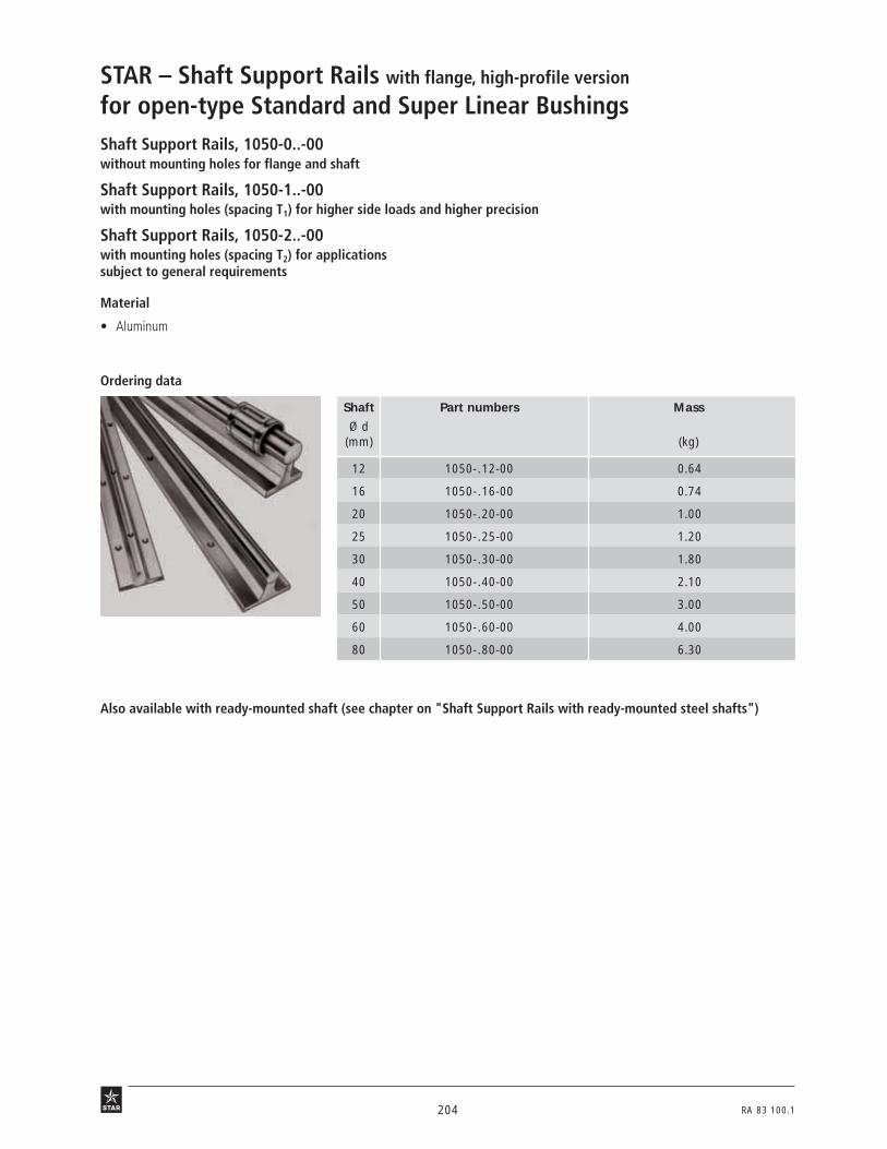
204 RA 83 100.1
Ordering data
63o1
Also available with ready-mounted shaft (see chapter on "Shaft Support Rails with ready-mounted steel shafts")
Shaft Support Rails, 1050-0..-00without mounting holes for flange and shaft
Shaft Support Rails, 1050-1..-00with mounting holes (spacing T1) for higher side loads and higher precision
Shaft Support Rails, 1050-2..-00with mounting holes (spacing T2) for applicationssubject to general requirements
STAR – Shaft Support Rails with flange, high-profile version
for open-type Standard and Super Linear Bushings
Material
• Aluminum
Shaft Part numbers Mass
Ø d(mm) (kg)
12 1050-.12-00 0.64
16 1050-.16-00 0.74
20 1050-.20-00 1.00
25 1050-.25-00 1.20
30 1050-.30-00 1.80
40 1050-.40-00 2.10
50 1050-.50-00 3.00
60 1050-.60-00 4.00
80 1050-.80-00 6.30

RA 83 100.1 205
63 0 2
Dimensions (mm) Hole spacing3)
Ø d H1) A V M M1 O1 U1 N E t O22) U2 T1 T2
±0.01 ISO 4762-8.8 DIN 7980 ISO 4762-8.8 DIN 125or
ISO 4017-8.8
12 28 43 5 5.8 9 M4x25 4 8 29 5.5 M4x12 4 75 120
16 30 48 5 7 10 M5x25 5 9 33 7 M5x16 5 100 150
20 38 56 6 8.3 11 M6x30 6 11 37 9.6 M6x16 6 100 150
25 42 60 6 10.8 14 M8x35 8 15 42 11 M6x16 6 120 200
30 53 74 8 11 14 M10x40 10 17 51 14 M8x25 8 150 200
40 60 78 8 15 18 M10x45 10 19 55 13.5 M8x25 8 200 300
50 75 90 10 19 22 M12x55 12 21 63 16 M10x30 10 200 300
60 80 100 12 25 30 M14x55 14 25 72 19 M10x30 10 300 –
80 100 125 14 34 42 M16x65 16 28 92 21.5 M12x35 12 300 –
Where extra-high precision and rigidity are required, the pitch of the center row of mounting holes (for attachment of the shaft) shouldbe reduced to 0.5 T1.
1) Relative to nominal shaft dimension d, measured when screwed to base mounting surface.2) Applies only to fixing in tapped holes in steel or cast iron.3) T1: for applications in which the load acts transverse to the open portion of the bushing and load capacity is near the load rating
limit, or where high dimensional accuracy is required.T2: for applications subject to general requirements.
Dimensions
TT/2600
-0.5-1.5
T/2
O1 U1
EA
25°
145°
V
O2
U2
N
MM1
d
t
H

206 RA 83 100.1
Shaft Support Rails, 1050-5..-00without mounting holes
Shaft Support Rails, 1050-6..-00hole spacing T1
Shaft Support Rails, 1050-7..-00hole spacing T2
64o1
Also available with ready-mounted shaft (see chapter on "Shaft Support Rails with ready-mounted steel shafts")
STAR – Shaft Support Rails with flange, low-profile version
for open-type Standard and Super Linear Bushings
Material
• Aluminum
Advantages
• Low overall heightUsed in conjunction with Linear Sets,these shaft support rails give linearmotion assemblies with extremely lowoverall as-installed heights.
• High rigidityThe shaft bearing surface of the supportrail is matched to the diameter of themating-size shaft to ensure that theshaft bearing pressure acts at the op-timum angle; together with the sturdydimensions of the mounting screws, thisguarantees high rigidity.
Shaft Part numbers Mass
Ø d(mm) (kg)
12 1050-.12-00 0.52
16 1050-.16-00 0.64
20 1050-.20-00 0.90
25 1050-.25-00 1.08
30 1050-.30-00 1.43
40 1050-.40-00 1.81
50 1050-.50-00 2.45
60 1050-.60-00 3.16
80 1050-.80-00 4.86
Ordering data

RA 83 100.1 207
Dimensions
6402/6403
Dimensions (mm) Hole spacing3)
Ø d H1) A V M O1 U1 N E t O22) T1 T2
±0.01 DIN6912-8.8 DIN7980 DIN6912-8.8
12 22 40 5 5.8 M4x20 4 8 29 4.5 M4x12 75 120
16 26 45 5 7 M5x20 5 9 33 7.6 M5x16 100 150
20 32 52 6 8.3 M6x25 6 11 37 8.6 M6x16 100 150
25 36 57 6 10.8 M8x30 8 15 42 9 M6x16 120 200
30 42 69 7 11 M10x35 10 17 51 10 M8x25 150 200
40 50 73 8 15 M10x40 10 19 55 9.5 M8x25 200 300
50 60 84 9 19 M12x45 12 21 63 11.5 M10x30 200 300
60 68 94 10 25 M14x50 14 25 72 13 M10x30 300 –
80 86 116 12 34 M16x60 16 28 92 15 M12x35 300 –
Where extra-high precision and rigidity are required, the pitch of the center row of mounting holes (for attachment of the shaft) shouldbe reduced to 0.5 T1.
1) Relative to nominal shaft dimension d, measured when screwed to base mounting surface.2) Applies only to fixing in tapped holes in steel or cast iron.3) T1: for applications in which the load acts transverse to the open portion of the bushing and load capacity is near the load rating
limit, or where high dimensional accuracy is required.T2: for applications subject to general requirements.
50º for 12÷4046º for 50÷80
M
d
N
t
H
V
E
A
T/2T600
145°
-0.5
-1.5
T/2
O1 U1
O2

208 RA 83 100.1
42b1
Shaft Part numbers Mass
Ø d(mm) (kg)
20 1054-220-00 1.1
25 1054-225-00 1.5
30 1054-230-00 2.1
40 1054-240-00 3.0
50 1054-250-00 4.2
43b1
series 1054-1..-..
series 1054-2..-..
Also available with ready-mounted shaft (see chapter on "Shaft Support Rails with ready-mounted steel shafts")
Shaft Support Rails, 1054-1..-00with fitting edgefor applications with stringent precision and rigidity requirements
Shaft Support Rails, 1054-2..-00with fitting edgefor applications with general precision and rigidity requirements
STAR – Shaft Support Rails side mounting
for open-type Standard and Super Linear Bushings
Material
• Aluminum
Ordering data
Shaft Part numbers Mass
Ø d(mm) (kg)
20 1054-120-00 1.0
25 1054-125-00 1.3
30 1054-130-00 1.9
40 1054-140-00 2.7
50 1054-150-00 3.7

RA 83 100.1 209
T/ 2
H 2
VV 1
O 1 O 2N
H 1
25°
Bt1
Md
U
145°t2
T/ 2 600-0.5
-1.5
E 1
T/ 4
E 2
T/ 2 T
42 B 2 43 B 2
1054-2..-..
Dimensions (mm)
Ø d H11) H2
1) V M E1 E2 T t1 t2 V12) B2) N O1 O2
3) Ujs6 ±0.012 ±0.15 ±0.15 max. ISO 4762-8.8 DIN 7980
20 52 7.5 15 8.3 8 22 75 8.5 8.5 4 30 11 M6x45 M6x16 6
25 62 10 20 10.8 10 26 75 15 11 5.5 36 15 M8x50 M8x20 8
30 72 12.5 25 11 12 30 100 15.3 13.5 7 42 17 M10x60 M10x25 10
40 88 15 30 15 12 38 100 19 16 8.5 50 21 M12x70 M12x30 12
50 105 17.5 35 19 15 45 100 24 18.5 9 60 25 M14x80 M14x35 14
1054-1..-..
Dimensions
1) Relative to nominal shaft dimension d, measured when screwed to base mounting surface.2) Recommended design: make mating surface without fitting edge (V1) and line up parallel via the shafts.3) Applies only to fixing in tapped holes in steel or cast iron.
1054-1..-.. 1054-2..-..
Dimensions (mm)
Ø d H11) H2
1) V M E T1 t1 t2 V12) B2) N O1 O2
3) Ujs6 ±0.012 ±0.15 max. ISO 4762-8.8 DIN 7980
20 52 7.5 15 8.3 15 100 8.5 8.5 4 30 11 M6x45 M6x16 6
25 62 10 20 10.8 18 120 15 11 5.5 36 15 M8x50 M8x20 8
30 72 12.5 25 11 21 150 15.3 13.5 7 42 17 M10x60 M10x25 10
40 88 15 30 15 25 200 17.5 16 8.5 50 19 M10x70 M12x30 10
50 105 17.5 35 19 30 200 21.5 18.5 9 60 21 M12x80 M14x35 12
Fitting edge Fitting edge
H 2
VV 1
O 1 O 2N
H 1
25°
Bt1
Md
U
145°t2
T 1/4
T 1
T 1/2
E
T 1/2
T 1/2
600-0.5
-1.5

210 RA 83 100.1
Shaft Support Rails, 1010-with Precision Steel Shaft
64o1
STAR – Shaft Support Rails with flange, low-profile version
for open-type Standard and Super Linear Bushings
Material
• Support rail: aluminum• Shaft: steel
Advantages
• Low overall heightUsed in conjunction with Linear Sets,these shaft support rails make itpossible to build linear motion guide-ways with an extremely low overallheight.
• High rigidityThe shaft bearing surface of the supportrail is matched to the diameter of themating-size shaft to ensure that the shaftbearing pressure acts at the optimumangle; together with the sturdy mount-ing screws, this guarantees high rigidity.
• Cost-effective useGreater height tolerances permit easyand cost-effective assembly of support-ed guideways.
Shaft Part numbers Mass
Ø d with shaft(mm) (kg/m)
16 1010-016-.. 2.5
20 1010-020-.. 3.8
25 1010-025-.. 5.4
30 1010-030-.. 7.6
40 1010-040-.. 12.6
Ordering data
available as of the year 2000
00 = shaft of heat-treatable steel, h601 = shaft of heat-treatable steel, h730 = shaft of corrosion-resistant steel, h631 = shaft of corrosion-resistant steel, h7
Ordering example:For a shaft support rail with a shaft of heat-treatable steel, 30 mm diameter,900 mm length, tolerance quality h7:1010-030-01 / 900 mm.
Only available with ready-mounted shaft.

RA 83 100.1 211
Dimensions
6402/6403
1) Measured with gauging shaft of nominal diameter d and length approx. 50 mm. Lengths up to 3000 mm with a parallelismof 0.1 mm on request.
2) Applies only to fixing in tapped holes in steel or cast iron.
M
d
N
t
H
V
E
A
T/2T
145°
T/2
O2
O1
50°
Dimensions (mm)
Ø d H1) A V M O1 N E t O22) T
±0.1 DIN 6912-8.8 DIN 6912-8.8
16 26 45 5 7 M5x20 9 33 6 M5x16 100
20 32 52 6 8.3 M6x25 11 37 7 M6x16 100
25 36 57 6 10.8 M8x30 15 42 7 M6x16 120
30 42 69 7 11 M10x35 17 51 7.5 M8x25 150
40 50 73 8 15 M10x40 19 55 7 M8x25 200

212 RA 83 100.1
Shaft Support Rails, 1025-with Precision Steel Shaft
64o1
STAR – Shaft Support Rails for ALU-STAR Profile Systems
for open-type Standard and Super Linear Bushings
Ordering data
1) Shaft support rail and shaft are supplied unmounted.
Ordering example:
For a shaft support rail with a shaft of heat-treatable steel, 25 mm diameter, 900 mmlength, tolerance quality h7:
1025-025-01 / 900 mm.
00 = shaft of heat-treatable steel, h601 = shaft of heat-treatable steel, h730 = shaft of corrosion-resistant steel, h631 = shaft of corrosion-resistant steel, h7
Shaft support rails with drilled holes, without shaft
Shaft Part numbers Mass LengthØ d
(mm) (kg/m) (mm)
20 1039-820-00 1.3 2880
25 1039-825-00 1.6 2880
30 1039-830-00 2.0 2880
Support rails with drilled holes, with shaft 1)
Shaft Part numbers Mass Combinable withØ d with shaft ALU-STAR Profile
profile width groove spacing(mm) (kg/m) (mm)
20 1025-020-.. 3.8 80 40
25 1025-025-.. 5.4 80 40
30 1025-030-.. 7.5 100 50
Material
• Support rail: aluminum• Shaft: steel
Advantages
• Fast and easy, modular assembly oflinear bushings and shafts on profilesystems
support rails, with shaft
-0.5-1.5
-0,5-1.5
-0.5-1.5
Shaft support rails without drilled holes, without shaft
Shaft Part numbers Mass LengthØ d
(mm) (kg/m) (mm)
20 1039-520-00 1.3 3000
25 1039-525-00 1.6 3000
30 1039-530-00 2.1 3000
-0.5-1.5
-0.5-1.5
-0.5-1.5
available as of the year 2000
Wellenunterstützung,mit Welle verschraubt
support rails, with drilled holes
support rails, without drilled holes

RA 83 100.1 213
Dimensions
6402/6403
Dimensions (mm)
Ø d H1) A V M O1 N E t O2 T±0.1 DIN 6912-8.8 DIN 6912-8.8
20 32 52 6 8.3 M6x25 11 40 7 M6 180
25 36 57 6 10.8 M8x30 15 40 7 M6 180
30 42 69 7 11 M10x35 17 50 7.5 M8 180
1) Measured with gauging shaft of nominal diameter d and length approx. 50 mm. Lengths up to 3000 mm with a parallelismof 0.1 mm on request.
M
d
N
t
H
V
E
A
T/2T
145°
T/2
O2
O1
50°

214 RA 83 100.1
Shaft Support Rails, 1013-without flange, with Precision Steel Shaft
41 B2
Ordering data
66o4
STAR – Shaft Support Rails without flange
for open-type Standard and Super Linear Bushings
Shaft Part numbers Mass
Ø d with shaft(mm) (kg/m)
12 1013-012-.. 1.1
16 1013-016-.. 1.9
20 1013-020-.. 3.0
25 1013-025-.. 4.5
30 1013-030-.. 6.3
Shaft Support Rail 1013- Conventional flanged designs
Material
00 = shaft of heat-treatable steel, h601 = shaft of heat-treatable steel, h730 = shaft of corrosion-resistant steel, h631 = shaft of corrosion-resistant steel, h7
Ordering example:
For a shaft support rail with a shaft of heat-treatable steel, 25 mm diameter,2500 mm length, tolerance quality h7:
1016-025-01 / 2500 mm.
Only available with ready-mounted shaft.
• Support rail: aluminum• Shaft: steel
Advantages
• These shaft support rails permit verycompact linear motion guideways andare ideal for designs where the steelshaft can be mounted from below.Compared with common flanged de-signs (see illustration), this elementbuilds exceptionally low.
• Cost-effective useGreater height tolerances allow simpleand cost-effective assembly of support-ed guideways.

RA 83 100.1 215
N
A
A125°
0
M
d
V1
145°S
T/2 TH
41 B3
Dimensions
Dimensions (mm)Ø d H1) A A1 V1 T S N M O
±0.05 ISO 4762-8.8
12 14.5 11 5.5 3 75 4.5 8 5.8 M4
16 18 14 7 3 75 5.5 9 7 M5
20 22 17 8.5 3 75 6.6 11 8.3 M6
25 26 21 10.5 3 75 9 15 10.8 M8
30 30 23 11.5 3 100 11 17 11 M10
Hole pattern:
1) Measured with gauging shaft of nominal diameter d and length approx. 50 mm. Lengths up to 3000 mm with a parallelism of 50 µmon request.

216 RA 83 100.1
Shaft Support Rails, 1016-with fitting edge, with Precision Steel Shaft
41 B2
Ordering data
66o4
Material
• Steel
00 = shaft of heat-treatable steel, h601 = shaft of heat-treatable steel, h730 = shaft of corrosion-resistant steel, h631 = shaft of corrosion-resistant steel, h7
STAR – Shaft Support Rails without flange
for open-type Standard and Super Linear Bushings
These steel shaft support rails produce verycompact linear motion assemblies and areideal for designs where the steel shaft canbe mounted from below. Compared withcommon flanged designs (see illustration),this element builds exceptionally low.
Shaft Part numbers Mass
Ø d with shaft(mm) (kg/m)
16 1016-016-.. 2.5
20 1016-020-.. 3.8
25 1016-025-.. 5.6
30 1016-030-.. 7.6
40 1016-040-.. 13.4
50 1016-050-.. 20.2
Ordering example:
For a shaft support rail with shaft of heat-treatable steel, 30 mm diameter,900 mm length, tolerance quality h7, the ordering data is:
1016-030-01 / 900 mm.
Shaft Support Rail 1016- Conventional flanged design
Only available with ready-mounted shaft.

RA 83 100.1 217
41 B3
NH1
A
A125°
0
M
d
HV1
145° S
T/2 T
Dimensions
Dimensions (mm) Tolerances within one grade (µm)
Shaft h6 Shaft h7Ø d H1) H1 A A1 V1 T S N M O H2) H1
3) H13)
±0.02 ±0.02 ISO 4762-8.8
16 18 26 14 7 3 75 5.5 9 7 M5 20 32 36
20 22 32 17 8.5 3 75 6.6 11 8.3 M6 20 33 38
25 26 38.5 21 10.5 3 75 9 15 10.8 M8 20 33 38
30 30 45 23 11.5 3 100 11 17 11 M10 20 33 38
40 39 59 30 15 4 100 13.5 21 15 M12 20 35 41
50 46 71 35 17.5 5 100 15.5 25 19 M14 20 35 41
1) Tolerance +0.02 mm; delivered graded by height to 20 µm.2) Measured with gauging shaft of nominal diameter d and length approx. 50 mm. Lengths up to 3000 mm with a parallelism of 10 µm
on request.3) Including shaft tolerance, measured when screwed to base mounting surface (statistically determined).
Fitting edge
Hole pattern:

218 RA 83 100.1
Shaft Part numbers Mass
Ø d(mm) (kg)
30 1052-130-00 9.0
40 1052-140-00 12.7
50 1052-150-00 20.7
60 1052-160-00 29.0
80 1052-180-00 48.9
66o3
Also available with ready-mounted shaft (see Chapter "Shaft Support Rails with ready-mounted steel shafts").
Shaft Support Rails, 1052-with fitting edge
STAR – Shaft Support Rails with flange
for Radial Linear Bushings
These steel shaft support rails afford veryhigh rigidity even when full advantage istaken of the high load capacity of the linearbushings.
Material
• Steel
Ordering data

RA 83 100.1 219
Dimensions
66 01
Dimensions (mm)
Ø d A H1) H12) V V1
3) M E T t1 t2 N O1 O2 Ujs6 js6 –0.5 ISO 4762-8.8 DIN 7980
30 80 50 40 19 7 13 55 60 22 13.5 17 M10x30 M10 10
40 100 60 50 22 8.5 18 70 75 22 16 21 M12x40 M12 12
50 125 75 62.5 30 9 23 90 100 28 21 28 M16x50 M16 16
60 150 90 75 34 13 27 110 120 34 25.5 32 M20x60 M20 20
80 200 115 100 42 18 37 140 150 38.5 30.5 40 M24x80 M24 24
1) Relative to nominal shaft dimension d, measured when screwed to base mounting surface.2) Applies exclusively at height V1.3) Recommended design: make mating surface without fitting edge (V1) and line up parallel via the shafts.
Fitting edge
Hole pattern:
H 1
dM
N
V 1
H
O 1 UE
A
O 2
t2 Vt1
135°
72°
TT/ 2600
-0.5
-1.5
T/ 2

220 RA 83 100.1
67o3
Also available with ready-mounted shaft (see Chapter "Shaft Support Rails with ready-mounted steel shafts").
Shaft Support Rails, 1053-with fitting edge
STAR – Shaft Support Rails side mounting
for Radial Linear Bushings
These steel shaft support rails afford veryhigh rigidity even when full advantage istaken of the high load capacity of the linearbushings.
Material
• Steel
Ordering data
Shaft Part numbers Mass
Ø d(mm) (kg)
30 1053-130-00 8.7
40 1053-140-00 15.5
50 1053-150-00 23.0
60 1053-160-00 36.0
80 1053-180-00 58.0
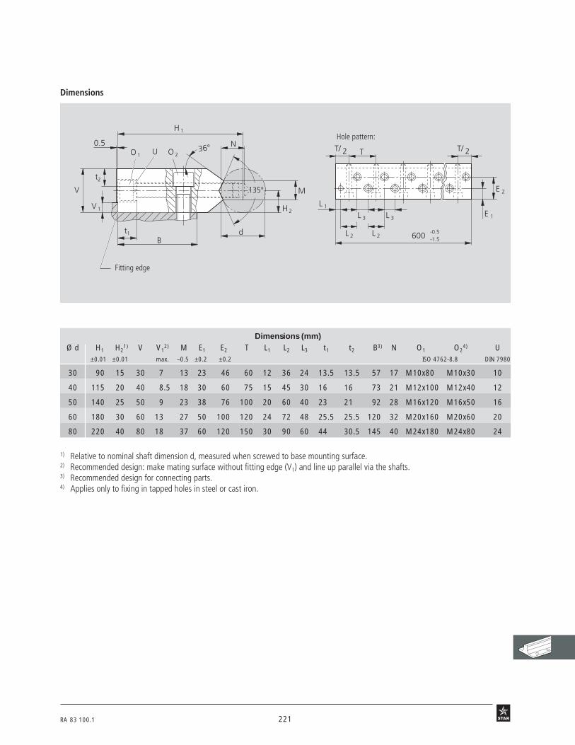
RA 83 100.1 221
Dimensions
67 01
Dimensions (mm)Ø d H1 H2
1) V V12) M E1 E2 T L1 L2 L3 t1 t2 B3) N O1 O2
4) U±0.01 ±0.01 max. –0.5 ±0.2 ±0.2 ISO 4762-8.8 DIN 7980
30 90 15 30 7 13 23 46 60 12 36 24 13.5 13.5 57 17 M10x80 M10x30 10
40 115 20 40 8.5 18 30 60 75 15 45 30 16 16 73 21 M12x100 M12x40 12
50 140 25 50 9 23 38 76 100 20 60 40 23 21 92 28 M16x120 M16x50 16
60 180 30 60 13 27 50 100 120 24 72 48 25.5 25.5 120 32 M20x160 M20x60 20
80 220 40 80 18 37 60 120 150 30 90 60 44 30.5 145 40 M24x180 M24x80 24
1) Relative to nominal shaft dimension d, measured when screwed to base mounting surface.2) Recommended design: make mating surface without fitting edge (V1) and line up parallel via the shafts.3) Recommended design for connecting parts.4) Applies only to fixing in tapped holes in steel or cast iron.
Fitting edge
Hole pattern:N
H 1
36° 0.5
V
t2
V 1
t1
O 1 O 2
Bd
135°
H 2
M
600 -0.5-1.5
T/ 2 T
E 1
E 2
L 1
L 3 L 3
L 2 L 2
U T/ 2

222 RA 83 100.1
Ordering data
69b1
Shaft Support Rails, 1012-with fitting edgewith Precision Steel Shaft h6 of heat-treatable steel
STAR – Shaft Support Rails with flange
for Radial Compact Sets
Material
• Steel
Shaft Part numbers Mass
Ø d with shaft(mm) (kg/m)
30 1012-030-00 12.3
40 1012-040-00 19.6
50 1012-050-00 31.0
60 1012-060-00 45.6
80 1012-080-00 79.2
Ordering example:
For a shaft support rail with shaft of 40 mm diameter, 2400 mm length, the ordering data is
1012-040-00 / 2400 mm.
70 b 1
Without fitting edge
• Align first shaft with the support rail (ready-mounted unit), using a straightedge,and screw into place.
• Align second shaft in parallel, preferably using a straightedge (see "Parallelism",General Technical Data and Mounting Instructions) and screw shaft support rail inplace.
• Push Radial Compact Sets onto the shafts and screw into place on the machine table.
With fitting edge
a) One fitting edge on the machine base and one on the machine table, or
b) only one fitting edge on the machine base.
• Press first shaft with support rail against fitting edge and screw into place.
• Align second shaft in parallel, preferably using a straightedge (see "Parallelism”,General Technical Data and Mounting Instructions) and screw shaft support rail intoplace.
• Push Radial Compact Sets onto the shafts andin case a) press Radial Compact Sets of the first shaft against fitting edge of the
machine table and screw into place; then screw Radial Compact Sets ofthe second shaft into place on machine table, or
in case b) screw Radial Compact Sets into place on machine table.
Mounting procedure
Only available with ready-mounted shaft.

RA 83 100.1 223
69 B2
TT/2
135°
M
d
N
t1
O1
E
A2
O2
V1
V
H3
t2
H4
72°
A3
Dimensions
1) Tolerance ±0.02; delivered graded by height to 20 µm.2) Measured (when screwed down) with gauging shaft of nominal diameter d and length approx. 50 mm.3) Including shaft tolerance, measured when screwed to base mounting surface (statistically determined).4) Lengths up to 3000 mm with a parallelism of 10 µm on request.
Dimensions (mm) Tolerances withinone grade (µm)
Shaft h6
Ø d A2 A3 H31) H4 V V1 M E O1 t1 N O2 t2 T H3
2) H43)
–0.5 DIN DIN6912-8.8 7984-8.8
30 68 34±0.02 33 48 11 6 13 46 M10x25 9 17 M10 6.8 60 204) 29
40 85 42.5±0.02 40 60 13 6 18 58 M12x30 10 21 M12 8.4 75 204) 31
50 105 52.5±0.02 50 75 17 8 23 74 M16x40 10.8 28 M16 10.5 100 204) 31
60 130 65±0.01 60 90 20 8 27 90 M20x40 16 32 M20 12.5 120 20 33
80 170 85±0.01 80 120 26 10 37 120 M24x60 16 40 M24 16 150 20 33
Fitting edge
Hole pattern:

224 RA 83 100.1
In linear motion systems with closed Linear Sets the guidingshafts are mounted at their ends. Precision Shaft SupportBlocks have been developed specifically for this purpose.
Advantages• Considerable cost benefits as compared with customer-built
designs
• High rigidity
• High dimensional accuracy makes elements interchangeable
STAR – Shaft Support Blocks

RA 83 100.1 225
17 B 1

226 RA 83 100.1
68o1
Shaft Support Blocks, 1055-
STAR – Shaft Support Blocks
For use with Linear Bushings or Linear Sets incorporating Standard or Super LinearBushings, closed or adjustable types, and with Linear Sets incorporating SegmentalLinear Bushings.
Material
• Spheroidal graphite cast iron
Ordering data
Shaft Part numbers Mass
Ø d(mm) (kg)
8 1055-008-00 0.03
12 1055-012-00 0.06
16 1055-016-00 0.12
20 1055-020-00 0.22
25 1055-025-00 0.37
30 1055-030-00 0.55
40 1055-040-00 0.97
50 1055-050-00 1.90
60 1055-060-00 3.60
80 1055-080-00 7.30

RA 83 100.1 227
68 02
EA
V
S
A1
H
d
SW
H 1
B
Dimensions (mm)
Ø d d H1) H12) A2) A1
2) B2) E S3) V2) SWH8
8 8 15±0.010 27 32 16 10 25±0.15 4.5 5 2.5
12 12 20±0.010 35 42 20 12 32±0.15 5.5 5.5 3
16 16 25±0.010 42 50 26 16 40±0.15 5.5 6.5 3
20 20 30±0.010 50 60 32 20 45±0.15 5.5 8 3
25 25 35±0.010 58 74 38 25 60±0.15 6.6 9 4
30 30 40±0.010 68 84 45 28 68±0.20 9.0 10 5
40 40 50±0.010 86 108 56 32 86±0.20 11.0 12 6
50 50 60±0.015 100 130 80 40 108±0.20 11.0 14 6
60 60 75±0.015 124 160 100 48 132±0.25 13.5 15 8
80 80 100±0.015 160 200 130 60 170±0.50 17.5 22 10
1) Relative to shaft nominal dimension d.2) Tolerance to DIN 1685 – GTB 15.3) Mounting screws to ISO 4762-8.8.
Dimensions

228 RA 83 100.1
Shaft Part numbers Mass
Ø d
(mm) (kg)
10 1057-010-00 0.05
12 1057-012-00 0.06
16 1057-016-00 0.11
20 1057-020-00 0.18
25 1057-025-00 0.35
30 1057-030-00 0.48
40 1057-040-00 0.90
50 1057-050-00 1.50
60 1057-060-00 3.0044 B1
Ordering data
For use with Linear Bushings or Linear Sets.
Shaft Support Blocks, 1057-
STAR – Shaft Support Blocks
Structural Design
• Rigid mounting of shaft due to extra-wide construction
• Centering bores provided for additionalpins
• With fitting edge(available as of the year 2000)
• Sizes 20 and 25 also for ALU-STARProfile Systems(available as of the year 2000)
Material
• Aluminum
For ALU-STAR Profile Systems
Shaft Part numbers Mass Combinable withALU-STAR Profile
Ø d profile width groove spacing
(mm) (kg) (mm) (mm)
20 1057-820-00 0.18 80 40
25 1057-825-00 0.35 100 50

RA 83 100.1 229
Dimensions50 B2 50 B3
Dimensions (mm)Ø d d H1) H1 M1) A B E E1
3) E23) S2) S1 S2
3) N1 N2 V SW H4
H8 ±0.01 ±0.01
10 10 18 31 20 40 20 27±0.15 17 13 5.3 M6 4 14 13 5 3 10
12 12 20 35 21.5 43 20 30±0.15 20 13 5.3 M6 4 16.5 13 5 3 10
16 16 25 42 26.5 53 24 38±0.15 26 16 6.6 M8 5 21 18 5 4 13
20 20 30 51 30 60 30 42±0.15 30 20 8.4 M10 6 25 22 5 5 16
25 25 35 61 39 78 38 56±0.15 40 25 10.5 M12 8 30 26 6.5 6 20
30 30 40 70 43.5 87 40 64±0.15 45 26 10.5 M12 8 34 26 8 6 22
40 40 50 88 54 108 48 82±0.15 65 32 13.5 M16 10 44 34 10 8 28
50 50 60 105 66 132 58 100±0.20 70 36 17.5 M20 12 49 42 12 10 37
60 60 75 130 82 164 74 124±0.20 90 46 22 M27 16 59 42 13 14 42
1) Relative to shaft nominal dimension d.2) Mounting screws to ISO 4762-8.8.3) Two centering holes for pins.
SW
H 1
B
S
S 1
HNN
2
2
2
1
d
E E
E
H445°
1
S
M
A
V
Dimensions (mm)Ø d d H4) H1 M4) A B E E1 E2 S5) S1 S2 N1 N2 V SW H4
H8 ±0.01 ±0.01
20 20 30 51 30 60 30 40±0.15 – – 6.6 – – 27 – 5 5 16
25 25 35 61 39 78 38 50±0.15 – – 9.0 – – 32 – 6.5 6 20
For ALU-STAR Profile Systems
4) Relative to shaft nominal dimension d.5) Mounting screws to ISO 4762-8.8.

230 RA 83 100.1
69o1
Shaft Support Blocks, 1056-with flange
STAR – Shaft Support Blocks
For use with Linear Bushings or Linear Sets, closed or adjustable type.
Ordering data
Shaft Part numbers Mass
Ø d
(mm) (kg)
12 1056-012-00 0.15
16 1056-016-00 0.21
20 1056-020-00 0.28
25 1056-025-00 0.41
30 1056-030-00 0.75
40 1056-040-00 1.65
50 1056-050-00 2.60
Flange-On Shaft SupportBlocks – ready-to-mountshaft support elementsThis element is the latest addition to ourrange of Flanged Linear Sets and has beendeveloped for use with Precision Steel Shaftsin cost-saving linear motion assemblies.
Material
• Lamellar graphite cast iron

RA 83 100.1 231
69 02
B E
EB
d
S
D
SW
V
L
Dimensions (mm)
Ø d d B1) L1) D1) E S V1) SWH7 H13
12 12 42 20 23.5 30±0.12 5.5 12 3
16 16 50 20 27.5 35±0.12 5.5 12 3
20 20 54 23 33.5 38±0.15 6.6 14 4
25 25 60 25 42.0 42±0.15 6.6 16 5
30 30 76 30 49.5 54±0.25 9.0 19 6
40 40 96 40 65.0 68±0.25 11.0 26 8
50 50 106 50 75.0 75±0.25 11.0 36 8
1) Tolerance to DIN 1686 – GTB 15.
Dimensions

232 RA 83 100.1
STAR – Shaft Support Blocks
Compact Shaft Support Blocks help to buildespecially space-saving structures as theyhave been specifically tailored to match thesmall outer dimensions of Compact LinearSets.
Material
• Aluminum
Ordering data
50 B1
For use with Linear Bushings or Compact Linear Sets.
Compact Shaft Support Blocks, 1058-
Shaft Part numbers MassØ d
(mm) (kg)
12 1058-012-00 0.045
16 1058-016-00 0.065
20 1058-020-00 0.110
25 1058-025-00 0.170
30 1058-030-00 0.220
40 1058-040-00 0.470
50 1058-050-00 0.820

RA 83 100.1 233
Dimensions50 B2 50 B3
Dimensions (mm)
Ø d d H1) H1 A B E S2) S1 N1 N2 H4 SWH8 ±0.01 ±0.15
12 12 19 33 40 18 27 5.3 M6 16 13 11 3
16 16 22 38 45 20 32 5.3 M6 18 13 13 3
20 20 25 45 53 24 39 6.6 M8 22 18 15 4
25 25 31 54 62 28 44 8.4 M10 26 22 17 5
30 30 34 60 67 30 49 8.4 M10 29 22 19 5
40 40 42 76 87 40 66 10.5 M12 38 26 24 6
50 50 50 92 103 50 80 13.5 M16 46 34 30 8
1) Relative to shaft nominal dimension d.2) Mounting screws to ISO 4762-8.8.
SW
H 1
B
S
S 1
HNN
21
d
A
E
H 445°

234 RA 83 100.1
Toronto
Los Angeles
São Paulo
Montevideo
Buenos Aires
Santiago de Chile
Caracas
Bogota
Mexico City
DallasAtlanta
Denver
Salt Lake City
Vancouver
Portland
York
St. Paul
Chicago
Cincinnati
Detroit
Rochester
Montreal
Indianapolis
Providence
Cleveland
Rexroth STARWorldwide availability and global service
Star Ball Linear Systems Ltd.Skibbereen, Ireland
Star Linear SystemsCharlotte, NC, USA
Cape ToBall Rail SystemsRoller Rail SystemsLinear Bushings and ShaftsScrew DrivesLinear Motion Systems

RA 83 100.1 235
Ahmedabad
Bangalore
Port Elizabeth
Johannesburg
Sydney
Melbourne Auckland
Jakarta
Singapore
Kuala Lumpur
Bangkok
ChengduShanghai
Mumbai
Tel Aviv YokohamaPusan
Hongkong
Rexroth Star GmbHSchweinfurt, Germany
Star-Recti Co. Ltd.Hsinshu, Taiwan
Locations in Europe:
Vienna, AustriaZaventem, BelgiumBrno, Czech RepublicHvidovre, DenmarkVantaa, FinlandMeaux, FranceHannover, GermanyLeipzig, GermanyMunich GermanyOffenbach, GermanyRatingen, GermanyStuttgart, GermanySt. Neots, Great BritainAthens, Greece
Budapest, HungarySkibbereen, IrelandMilan, ItalyAlmere, NetherlandsLanghus, NorwayPruszkow, PolandPorto, PortugalMaribor, SloveniaZelezniki, SloveniaBarcelona, SpainSan Sebastian, SpainHelsingborg, SwedenFeuerthalen, SwitzerlandIstanbul, Turkey
Production plants
Regional sales offices
pe Town
Cairo
Peking

Bosch Rexroth Linear Motion and Assembly Technologiesdivision offers a complete line of STAR linear motion products...
Copyright© BOSCH REXROTH 2001All rights reseved.
Supersedes all previous issues.The illustrations and drawings in thecatalog show principles of design oroperation and are for reference only,subject to alteration without notice.
This catalog or any part thereof maynot be reproduced without ourwritten permission.
STAR Ball Rail® SystemsRA 82 201
STAR Roller RailsTM
RA 82 301
Metric Linear BushingsRA 83 100
STAR Precision Ball ScrewsRA 83 301
STAR Linear ModulesRA 82 402
STAR Compact ModulesRA 82 601
STAR Linear Motion SlidesRA 83 001
STAR Ball Rail® TablesRA 82 501
STAR Ball TransfersRA 82 910
Hollow Shaft MotorRA 83 315
Tychoway® Linear Roller BearingsRA 99 001
Integrated Measuring SystemRA 82 350
Miniature Ball Rail®
SystemsRA 82 210
Mini Compact SlidesRA 99 007
Tychoway® Roller SlidesRA 99 000
Bosch Rexroth CorporationLinear Motion and Assembly Technologies14001 South Lakes Drive • Charlotte, NC 28273 • Telephone: (704)583-4338 • (800)438-5983Telefax: (704)583-0523 • http://boschrexoth-us.com Ô Ô Ô E-mail: [email protected]
STAR, Ball Rail, and are registeredtrademarks of Deutsche Star GmbH,Schweinfurt, Germany
Inch Linear BushingsRA 99 110