Embed Size (px)
Citation preview

LifeSize® Video Communications Systems User Guide

2 LifeSize Video Communications Systems User Guide
November 2009Copyright Notice©2005 - 2009 LifeSize Communications Inc, and its licensors. All rights reserved.LifeSize Communications has made every effort to ensure that the information contained in this document is accurate and reliable, but assumes no responsibility for errors or omissions. Information in this document is subject to change without notice. Companies, names, and data used in examples herein are fictitious unless noted. This document contains copyrighted and proprietary information, which is protected by United States copyright laws and international treaty provisions. No part of the document may be reproduced or transmitted, in any form or by any means, electronic or mechanical, for any purpose, without the express written permission from LifeSize Communications.
Trademark AcknowledgmentsLifeSize® is the trademark of LifeSize Communications Inc. All other trademarks are the property of their respective owners.
Patent NoticeFor patents covering LifeSize® products, refer to http://www.lifesize.com/support/legal.
Contacting Customer SupportIf you have questions, concerns, or need assistance, contact your LifeSize Partner.
Providing Customer FeedbackLifeSize Communications welcomes your comments regarding our products and services. If you have feedback about this or any LifeSize product, please send it to [email protected]. Contact information for LifeSize Communications is as follows:
Method Address
Internet http://www.lifesize.com
E-mail [email protected]
Phone (877) LIFESIZE or (877) 543-3749(512) 347-9300
Fax (512) 347-9301

LifeSize Video Communications Systems User Guide 3
Using LifeSize Video Communications SystemsThis guide explains how to use the following LifeSize video communications systems to place and manage calls:
• LifeSize Room series
• LifeSize Team series
• LifeSize Express series
For information about using LifeSize Passport, refer to the LifeSize Passport User Guide. For information about how to install a LifeSize video communications system, refer to the installation guide for your LifeSize system model.
Related documentation is available from the documentation CD included with the product and from the Support page of www.lifesize.com. Release Notes, technical notes, and technical reference publications are available from the Support page of www.lifesize.com.
4 LifeSize Video Communications Systems User Guide
System ComponentsBefore using your LifeSize video communications system, familiarize yourself with its components.
CameraNear end participants and objects in a video conference call are located in the same room as your LifeSize video communications system. Far end participants and objects are in a remote location. The camera captures near end video to send to far end participants in a call. One or more cameras may be connected to the system, depending on the system model and its capabilities.
LifeSize CameraLifeSize Camera 200
LifeSize Focus
LifeSize Video Communications Systems User Guide 5
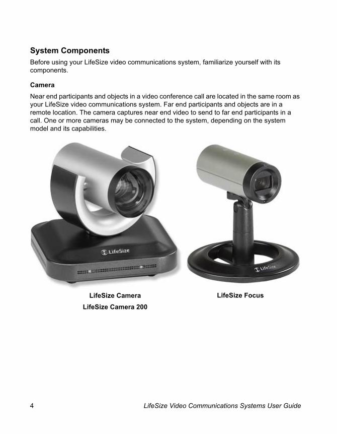
MicrophoneA LifeSize system includes a device with one or more microphones for audio input during a call. Depending on the model and optional peripherals purchased, the system may have one or more of the following devices.
The LifeSize Phone high definition audio conferencing speakerphone is fully integrated with LifeSize video communications systems and doubles as the microphone for a video system. LifeSize Phone provides 16 microphones in a circular array to capture local sound. You can also use the LifeSize Phone to place and hang up calls.
LifeSize MicPod includes a single omni-directional microphone, mute button and mute status LEDs.
LifeSize Focus is a camera that includes two omni-directional microphones.
Note: Only one of these devices can be the active microphone during a call. If more than one type appears to be connected to the system, the Active Microphone field in the System Information page identifies which device is serving as the active microphone. To access the System Information page, refer to “The System Menu” on page 11.
LifeSize MicPod LifeSize FocusLifeSize Phone

6 LifeSize Video Communications Systems User Guide
CodecThe LifeSize codec compresses outgoing video and audio content and data, transmits this information to the far end of a call, and decompresses incoming information. You should not need to interact with the codec once it has been properly installed in your environment.
Third Party DisplayA third party display connected to the LifeSize codec enables you to access the user interface and view video images during a video call. A second display may be connected to the LifeSize codec if the system supports more than one display.

LifeSize Video Communications Systems User Guide 7
Remote ControlThe LifeSize remote control provides wireless control of all LifeSize video communications system functions and enables you to navigate the user interface, place and receive calls, and control cameras connected to the system. A system includes one of the following remote controls:
Instructions in this manual for performing tasks with the remote control use the headings Black Remote Control and Silver Remote Control to identify an instruction that applies only to that remote control model.
Black Remote Control Silver Remote Control
8 LifeSize Video Communications Systems User Guide
Navigating the User InterfaceWhen your LifeSize system is idle, a screen saver appears on the display, or the screen is black. An incoming call or pressing any button on the remote control automatically invokes the system.
Note: Administrators can configure LifeSize systems for use in telepresence rooms in which a conference administrator controls calls from a control panel or where users interact with the system using a connected phone. If telepresence is enabled on your LifeSize system, only an administrator can access the user interface when the system is idle. During a call, you can perform only the following tasks in the user interface:
• Change the behavior of the numeric keys on the remote control from Touch Tones to Presets. Refer to “Using Camera Presets During a Call” on page 30.
• View call statistics. Refer to “Viewing Call Statistics” on page 35.
• Choose video input with the remote control. Refer to “Changing Video Inputs” on page 30.
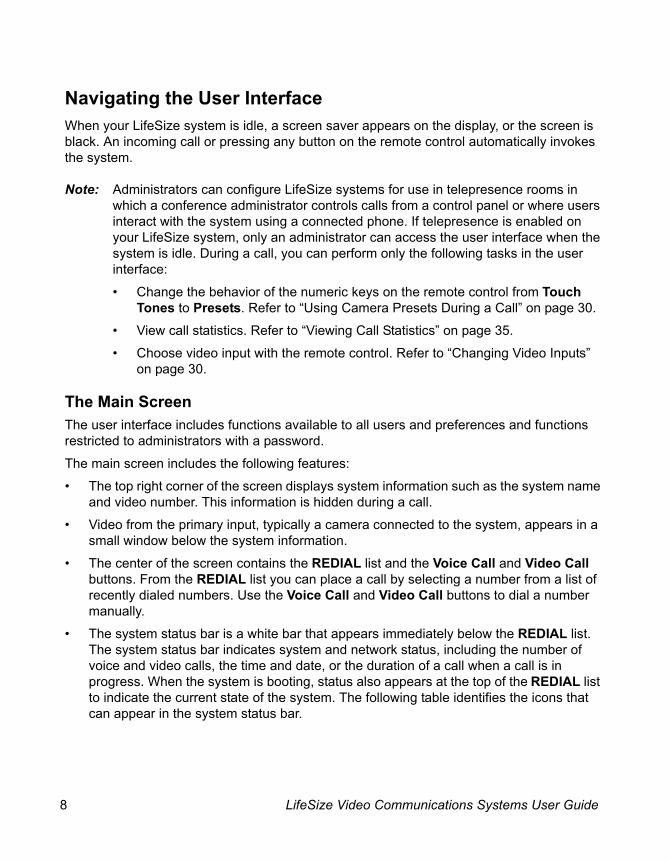
The Main ScreenThe user interface includes functions available to all users and preferences and functions restricted to administrators with a password.
The main screen includes the following features:
• The top right corner of the screen displays system information such as the system name and video number. This information is hidden during a call.
• Video from the primary input, typically a camera connected to the system, appears in a small window below the system information.
• The center of the screen contains the REDIAL list and the Voice Call and Video Call buttons. From the REDIAL list you can place a call by selecting a number from a list of recently dialed numbers. Use the Voice Call and Video Call buttons to dial a number manually.
• The system status bar is a white bar that appears immediately below the REDIAL list. The system status bar indicates system and network status, including the number of voice and video calls, the time and date, or the duration of a call when a call is in progress. When the system is booting, status also appears at the top of the REDIAL list to indicate the current state of the system. The following table identifies the icons that can appear in the system status bar.

LifeSize Video Communications Systems User Guide 9
Icon Condition
Video Indicates the number of video calls in progress. Each orange circle that appears to the right of the video icon represents a video call in progress.
Voice Indicates the number of voice calls in progress. Each orange circle that appears to the right of the voice icon represents a voice call in progress.
Indicates that the communication subsystem is initializing. If this icon reappears after the system has booted, a problem has occurred. Reboot the system.
Indicates that the system is initializing. When the system is initializing, functionality on the main screen is disabled and no entries appear in the REDIAL list. This icon also appears when a new device is connected to the system after the system boots and disappears when the device is ready. If the icon persists, a problem has occurred and rebooting the system is necessary.
Indicates that the system does not have an active microphone. Contact your administrator.
Indicates that LifeSize Networker connected to the codec is initializing. Most of the main screen elements are not visible. If LifeSize Networker never fully initializes, the red icon persists until either LifeSize Networker or the system is rebooted. Contact your administrator.
Indicates that LifeSize Networker connected to the codec has initialized and is attempting to connect to the ISDN network. If this icon persists, contact your administrator.
Indicates that the phone connected to the system is booting.
Indicates that the system is performing configuration changes to enable FIPS 140-2 security. If an administrator has enabled FIPS 140-2 security on the system, this icon appears after a system reboot and disappears when the configuration changes are complete. If this icon persists, contact your administrator. For more information, refer to the LifeSize Video Communications Systems Administrator Guide.

10 LifeSize Video Communications Systems User Guide
• The navigation bar is a grey bar that appears below the system status bar. The navigation bar contains icons that correspond to buttons on the remote control and text that describes the action a button performs. The icons and text change depending on how you use the system. The quick reference card Getting Started with your LifeSize Video System shows you how to perform common tasks with the remote control.
Note: Pressing and holding any button except the OK button on the remote control may cause the command associated with the button to repeat.
Network Status
Identifies the network status, as follows:connected (green indicator)
in progress (yellow indicator)
disconnected (red indicator)
System Overheating
This yellow indicator warns you when the system temperature is above normal operating temperature. The codec adjusts fan speed automatically to cool itself.This red indicator warns that the system is overheated and approaching the maximum allowed operating temperature and will automatically reboot after reaching it.
Warning: Temperatures that require the codec to reboot can permanently damage codec components. Ensure the room that houses the codec is properly ventilated and temperature controlled.
SIP server registration status
When SIP is configured as the protocol for placing calls, this indicator identifies the registration status of the LifeSize system with the SIP server as follows:in progress (yellow indicator)
registration failed (red indicator)Contact your administrator.
H.323 gatekeeper registration status
Indicates the registration status of the LifeSize system with an H.323 gatekeeper as follows:in progress (yellow indicator)
registration failed (red indicator)Contact your administrator.
Icon Condition
LifeSize Video Communications Systems User Guide 11
Selecting Objects on the Main ScreenUse the arrow keys on the remote control to navigate the main screen. As you navigate to different parts of the screen, the icons and their descriptions that appear in the navigation bar change to indicate what actions are available for a selected object or screen.
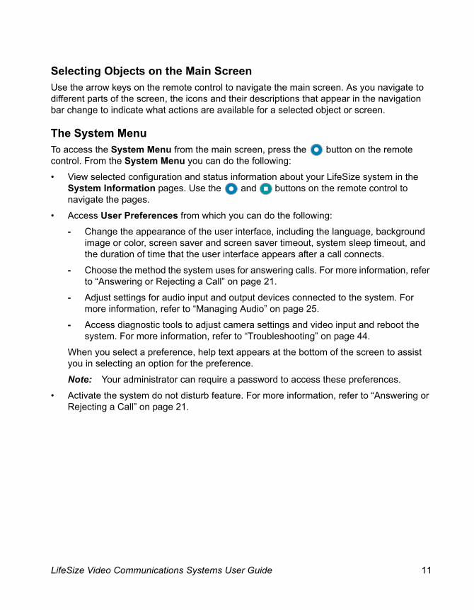
The System MenuTo access the System Menu from the main screen, press the button on the remote control. From the System Menu you can do the following:
• View selected configuration and status information about your LifeSize system in the System Information pages. Use the and buttons on the remote control to navigate the pages.
• Access User Preferences from which you can do the following:
- Change the appearance of the user interface, including the language, background image or color, screen saver and screen saver timeout, system sleep timeout, and the duration of time that the user interface appears after a call connects.
- Choose the method the system uses for answering calls. For more information, refer to “Answering or Rejecting a Call” on page 21.
- Adjust settings for audio input and output devices connected to the system. For more information, refer to “Managing Audio” on page 25.
- Access diagnostic tools to adjust camera settings and video input and reboot the system. For more information, refer to “Troubleshooting” on page 44.
When you select a preference, help text appears at the bottom of the screen to assist you in selecting an option for the preference.
Note: Your administrator can require a password to access these preferences.
• Activate the system do not disturb feature. For more information, refer to “Answering or Rejecting a Call” on page 21.

12 LifeSize Video Communications Systems User Guide
Controlling Cameras Become familiar with how to control a camera connected to your system before placing a video call. The System Information page identifies the type of camera connected to the system. If the camera type is pan, tilt, and zoom, you can control the camera with the remote control. To prevent far end users from controlling your near end camera during a call, contact your administrator.
Controlling a Near End CameraTo adjust the near end camera when the system is idle, select the camera.
Black Remote Control:Press the near/far camera button on the remote control.
Silver Remote Control:Press the near camera button.
Use the following buttons on the remote control to adjust the camera angle:
If you are using LifeSize Room with two cameras, only one camera can be active and capturing video images at any time, even if all cameras are connected to the system. To specify the active camera, refer to “Changing Video Inputs” on page 30. On the Primary Input and Presentation Input selection screens, the inactive camera appears as a camera icon in a grey selection box. The active camera appears as a selection box with its video image. The blue LED of the active camera is brightly lit when the system is in use. The blue LED of an inactive camera is dimly lit. If you disconnect the active camera, the inactive camera automatically becomes the active camera. Reconnecting the disconnected camera does not change the active camera selection.
Remote Control Button Function
Left and right arrows pan the camera.Up and down arrows tilt the camera.
Zoom in and zoom out keys make objects appear closer or farther away.
LifeSize Video Communications Systems User Guide 13
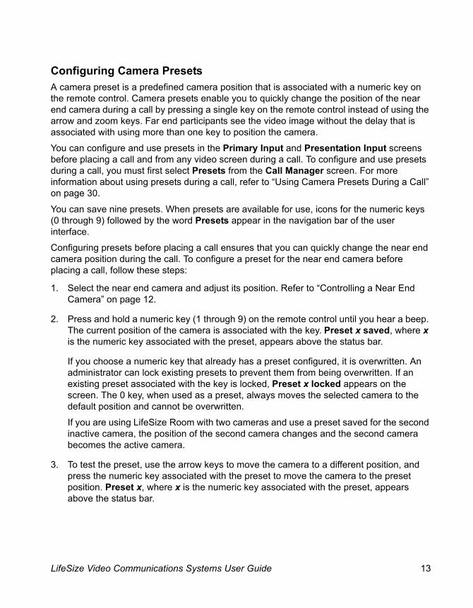
Configuring Camera PresetsA camera preset is a predefined camera position that is associated with a numeric key on the remote control. Camera presets enable you to quickly change the position of the near end camera during a call by pressing a single key on the remote control instead of using the arrow and zoom keys. Far end participants see the video image without the delay that is associated with using more than one key to position the camera.
You can configure and use presets in the Primary Input and Presentation Input screens before placing a call and from any video screen during a call. To configure and use presets during a call, you must first select Presets from the Call Manager screen. For more information about using presets during a call, refer to “Using Camera Presets During a Call” on page 30.
You can save nine presets. When presets are available for use, icons for the numeric keys (0 through 9) followed by the word Presets appear in the navigation bar of the user interface.
Configuring presets before placing a call ensures that you can quickly change the near end camera position during the call. To configure a preset for the near end camera before placing a call, follow these steps:
1. Select the near end camera and adjust its position. Refer to “Controlling a Near End Camera” on page 12.
2. Press and hold a numeric key (1 through 9) on the remote control until you hear a beep. The current position of the camera is associated with the key. Preset x saved, where x is the numeric key associated with the preset, appears above the status bar.
If you choose a numeric key that already has a preset configured, it is overwritten. An administrator can lock existing presets to prevent them from being overwritten. If an existing preset associated with the key is locked, Preset x locked appears on the screen. The 0 key, when used as a preset, always moves the selected camera to the default position and cannot be overwritten.
If you are using LifeSize Room with two cameras and use a preset saved for the second inactive camera, the position of the second camera changes and the second camera becomes the active camera.
3. To test the preset, use the arrow keys to move the camera to a different position, and press the numeric key associated with the preset to move the camera to the preset position. Preset x, where x is the numeric key associated with the preset, appears above the status bar.

14 LifeSize Video Communications Systems User Guide
Managing Near End Video QualityBefore you place a call, examine the near end video image from the camera connected to your LifeSize system. If the image flickers, colors appear unbalanced, or the image appears too dark, you may need to adjust the room lighting or camera settings. For more information, refer to “Adjusting Room Lighting” on page 44 and “Camera Issues” on page 45.
Using Digital ZoomDigital zoom electronically crops an area of the video image that appears in the display using the same aspect ratio as the original image and then scales the cropped image to the dimensions of the original image. Digital zoom is available with LifeSize Focus and LifeSize Camera connected to LifeSize Express, LifeSize Express 200, LifeSize Room 200, LifeSize Room 220, LifeSize Team 200, and LifeSize Team 220.
Digital zoom is available with LifeSize Camera only after the camera’s longest focal length with optical zoom has been reached. Camera presets are not supported with LifeSize Camera while using digital zoom. Using a camera preset while in digital zoom returns the camera to optical zoom.
Note: Image quality may degrade when using digital zoom.
By default, digital zoom is disabled. Only administrators can enable this feature.
To use digital zoom, do the following:
1. Ensure that the camera is selected as the primary video input. Digital zoom is available only when the camera is selected as the primary video input. For more information about selecting a device as the primary video input, refer to “Changing Video Inputs” on page 30.
2. If the system is idle, select the near end camera to control. Refer to “Controlling a Near End Camera” on page 12. During a call, the near camera is selected by default. An orange and white camera icon appears in the near video image when the user interface is visible and the near end camera is selected.
3. Depending on the camera you are using, do one of the following:
- If you are using LifeSize Focus, press the zoom in button on the remote control to obtain a closer view of the near end video image.
- If you are using LifeSize Camera, press and hold the zoom in button on the remote control until you hear a beep, and then release the zoom in button. The beep indicates that you have reached the longest focal length with the camera’s optical zoom. Press the zoom in button again to use digital zoom.

LifeSize Video Communications Systems User Guide 15
4. Use the arrow keys on the remote control to digitally pan and tilt the camera. Depending on the camera you are using, digital pan and tilt behave as follows:
- If you are using LifeSize Focus, digital pan and tilt are available only after you activate digital zoom by pressing the zoom in button. If you exit digital zoom by using the zoom out button to return to the camera’s original fixed focal length, digital pan and tilt are not available.
- If you are using LifeSize Camera, digital pan and tilt are available only when using digital zoom and only after the camera’s mechanical limits of pan and tilt have been reached.
5. Use the zoom out button to view the image from farther away or to exit digital zoom.
Placing a CallYou can place a video or voice call with your LifeSize system in the following ways:
• Select a stored number from the REDIAL list on the main screen or from the directory.
• Manually dial a number using the following:
- Video Call or Voice Call buttons on the main screen
- video or voice keys on the LifeSize Phone if connected to your system
When placing a video call using the remote control or the video button on the LifeSize Phone, you can dial either phone numbers or IP addresses. This enables systems inside a corporate network without access to a gateway to call other LifeSize Phones in the network using system IP addresses.
Using a comma in a number specifies a one-second pause in the dialing sequence. This may be required, for example, when placing a PSTN call that requires a pause after dialing the first number to obtain an outside line. You can use more than one comma to increase the duration of the pause, if needed.
If LifeSize Networker is configured for use with the system and you enter # as the first character when placing a call, the system attempts to dial the call first as an ISDN number.

16 LifeSize Video Communications Systems User Guide
When you place a call, the Call Status dialog appears and closes when the call connects. The voice icon appears in the Call Status dialog and in the status bar regardless of the type of call (video or voice) that you placed. When the call connects, the icon that corresponds to the type of call you placed, voice or video appears in the status bar and in the REDIAL list entry for the call.
Note: Calling your own LifeSize system is not supported or recommended. If the system supports multiway video calls, this action produces infinite looping windows in the connected display. If the system supports only two way video calls, this action produces a busy signal. Calling a device multiple times during the same call produces a similar result and is not supported or recommended.
Placing a Call from the REDIAL ListThe REDIAL list on the main screen stores up to 15 recently dialed numbers. A scroll bar appears when more than five entries are available for selection. The oldest entry in the list is automatically removed when the system receives a call after the maximum number of entries has been reached.
The last call placed always appears at the top of the list. The entry includes the name of the party called and an icon that indicates whether the number is a voice or video
number. The entry’s number (and bandwidth if the entry is a video number) appears below the list when the entry is selected. If the system receives a call, but does not answer it, the call appears in the REDIAL list as a missed call. The symbol appears next to the name in the entry. The date and time of the missed call appear below the REDIAL list when the entry is selected.
To place a call from the REDIAL list, use the arrow keys on the remote control to select an entry and press OK.
To change the bandwidth for a video call on the REDIAL list before placing the call, select Video Call on the main screen, press OK twice, and use the right arrow key to select the bandwidth list. Change the bandwidth to a setting other than Auto.
Note: Selecting Auto from the Video Call selection before placing a call does not change the bandwidth selection for an entry on the REDIAL list that does not have Auto as its last called bandwidth.
You can adjust the maximum number of entries that appear in the REDIAL list by adjusting the Maximum Redial Entries preference in User Preferences : Calls.
Note: The None option for the Maximum Redial Entries preference removes existing entries from the REDIAL list and prevents new entries from appearing on the list.
LifeSize Video Communications Systems User Guide 17
You can also add entries from the REDIAL list to the local directory and manually remove entries or lock them to prevent them from being automatically removed when the maximum number of entries is reached. For more information, refer to “Managing the REDIAL List” on page 38.
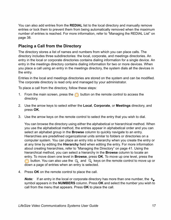
Placing a Call from the DirectoryThe directory stores a list of names and numbers from which you can place calls. The directory includes three subdirectories: the local, corporate, and meetings directories. An entry in the local or corporate directories contains dialing information for a single device. An entry in the meetings directory contains dialing information for two or more devices. When you place a call using an entry in the meetings directory, the system dials all the devices in the entry.
Entries in the local and meetings directories are stored on the system and can be modified. The corporate directory is read only and managed by your administrator.
To place a call from the directory, follow these steps:
1. From the main screen, press the button on the remote control to access the directory.
2. Use the arrow keys to select either the Local, Corporate, or Meetings directory, and press OK.
3. Use the arrow keys on the remote control to select the entry that you wish to dial.
You can browse the directory using either the alphabetical or hierarchical method. When you use the alphabetical method, the entries appear in alphabetical order and you can select an alphabet group in the Browse column to quickly navigate to an entry. Hierarchies are predefined organizational units similar to folders or directories on a computer system. You can place an entry into a hierarchy when you create the entry or at any time by editing the Hierarchy field when editing the entry. For more information about creating hierarchies, refer to “Managing the Directory” on page 41. Using the hierarchical method, you can select a hierarchy in the Browse column to locate an entry. To move down one level in Browse, press OK. To move up one level, press the
button. You can also use the and keys on the remote control to move up or down a page of entries when an entry is selected.
4. Press OK on the remote control to place the call.
Note: If an entry in the local or corporate directory has more than one number, the symbol appears in the NUMBERS column. Press OK and select the number you wish to call from the menu that appears. Press OK to place the call.

18 LifeSize Video Communications Systems User Guide
You can also add, remove, or edit entries in the directory. For more information, refer to “Managing the Directory” on page 41.
Manually Dialing a Number from the Main ScreenUse the Video Call and Voice Call selections on the main screen to dial a video or voice number manually using the remote control.
Manually Dialing a Video NumberTo dial a video number manually from the main screen, follow these steps:
1. Use the arrow keys on the remote control to select Video Call and press OK.
2. Enter the number you wish to call. The last manually entered number appears by default. To edit the number, use the following keys:
- The button changes the text entry method (indicated at the bottom of the screen).
Note: The 0x1a option enables you to enter an IPv6 address when your LifeSize system is connected to an IPv6 network. If IPv6 addressing is enabled on your LifeSize system, the IPv6 address of the system appears on the System Information page in the System Menu. If you enter an IPv6 address, the system you are calling must support IPv6 addressing for the call to connect.
- The button behaves as backspace.
- The button displays the keyboard from which you can enter alphanumeric characters. Use the arrow keys to navigate to the character you wish to enter and press OK.
Press OK to exit the field.
3. Optional: Navigate to the list that appears next to the entry box for numbers and choose a value for the maximum bandwidth for the call. Press OK to access the list, use the arrow keys to select a value, and press OK again to save your selection.
4. Press the call button to dial the number.

LifeSize Video Communications Systems User Guide 19
Manually Dialing a Voice NumberTo dial a voice number manually from the main screen, follow these steps:
1. Use the arrow keys on the remote control to select Voice Call and press OK.
2. Enter the number you wish to call. The last manually entered number appears in this field by default. To edit the number, use the following keys:
- The button changes the text entry method (indicated at the bottom of the screen).
- The button behaves as backspace.
- The button displays the keyboard from which you can enter alphanumeric characters. Use the arrow keys to navigate to the character you wish to enter and press OK.
Using a comma in a number specifies a one-second pause in the dialing sequence. This may be required, for example, when placing a PSTN call that requires a pause after dialing the first number to obtain an outside line.
3. Press call to place the call.
Manually Dialing a Number with LifeSize PhoneWhen LifeSize Phone is connected to your LifeSize video conferencing system, you can manually dial a voice or video call using the keys on the phone keypad. To place a call, press the voice or video keys and enter the number using the numeric keys.
When placing a call using the voice button on the LifeSize Phone and voice dialing is set to touch tone (or pulse on LifeSize Room, and LifeSize Team MP), you can dial only phone numbers using PSTN connectivity. When voice dialing is set to VoIP, you can dial IP addresses as well as phone numbers.

20 LifeSize Video Communications Systems User Guide
Including Multiple Sites in CallsIf your system is hosting a conference call (all callers are connecting to your system), you can add participants to an existing call at any time up to the maximum connections allowed for the system. You can add a second participant while the first call is connecting; you do not need to wait for the first call to connect. If you attempt to add a participant after the system limit has been reached, the message Maximum Calls Reached appears in the Call Status window.
To add participants to an existing call, follow these steps:
1. Black Remote Control: Press the button to return to the main screen to add a new caller.
Silver Remote Control:Press the button to return to the main screen to add a new caller.
2. Do one of the following:
- Select a number from the REDIAL list and press OK. An orange LED indicator appears in the REDIAL list to the left of the voice or video numbers currently in a call.
- Select a number from the directory. Refer to “Placing a Call from the Directory” on page 17.
- Dial a number manually using the Voice Call or Video Call selections. Refer to “Manually Dialing a Number from the Main Screen” on page 18.
- Press the add key on the phone keypad and enter the new number. Press the voice key or the video key on the phone keypad, depending on the type of call you are placing.
Note: If a call connects using PSTN connectivity, you must use the remote control to add calls.
LifeSize Video Communications Systems User Guide 21
Answering or Rejecting a CallYou can configure your system to automatically answer incoming calls by setting preferences in User Preferences : Calls as follows:
• Auto Answer—If set to Enabled, the system automatically answers the first incoming call. If set to Disabled (the default), you must manually answer incoming calls.
If your system is configured for answering calls manually, choose one of the following options when an incoming call arrives:
- Select Answer and press OK to accept the call.
- Select Ignore and press OK to reject the call.
Note: When Auto Answer is set to Enabled, the system answers a PSTN call only if another call is already connected.
• Auto Answer Mute—If set to Enabled (the default), and the Auto Answer preference is set to Enabled, the system is muted when a call connects.
• Auto Answer Multiway Call—If set to Enabled (the default), the system automatically answers incoming calls after the first call has connected. The system beeps to indicate when a new call connects.
If Auto Answer Multiway Call is set to Enabled, the New Call Automatically Answered dialog appears when video is not available from the incoming call because of any of the following conditions:
- The second or subsequent incoming call is a voice call. The name and number of the added voice caller appears in the dialog.
- The system supports more than four video participants and a fifth or subsequent video participant joins the call. LifeSize systems that support multiway calls can show video images from a maximum of four video participants.
- The system supports and is configured to show video only from the participant currently speaking or from the last speaker if your site is the current speaker.
Select Hang Up and press OK to hang up the call. If you ignore the dialog, the system accepts the call.

22 LifeSize Video Communications Systems User Guide
Enabling Do Not Disturb During CallsIf you receive an incoming call while you are in another call and Auto Answer Multiway Call is set to Disabled, you can choose Do Not Disturb which ignores the incoming call and prevents any other calls from interrupting for the duration of the call. The caller hears a busy signal. Calls missed while the do not disturb feature is enabled appear in the REDIAL list on the main screen.
Regardless of the setting for the Auto Answer Multiway Call preference, at any time during a call you can enable the do not disturb feature from any call screen by doing the following:
1. Press OK on the remote control. The Call Manager appears.
2. Use the arrow keys to navigate to Do Not Disturb.
3. Press OK.
Using System Do Not DisturbYou can enable the system do not disturb feature to show only the background image of the main screen with the status and navigation bars and a system do not disturb message. When the system do not disturb feature is enabled, the system responds only to the volume control buttons and the OK button on the remote control. Callers hear a busy signal and missed calls appear in the REDIAL list. Consider using this feature, for example, if you are using the meeting room for a purpose other than a video conference and do not wish to be disturbed by incoming calls.
To enable this feature, follow these steps:
1. From the main screen, access the system menu by pressing the button on the remote control.
2. Use the down arrow key to select Do Not Disturb on the System Menu.
3. Click OK.
A dialog appears indicating that the system do not disturb feature is enabled. Press OK to return the system to normal operation.

LifeSize Video Communications Systems User Guide 23
Managing a CallDuring a call, you can view information about the status of the call and the identity of connected callers. You can also manage audio output and video images, control cameras, select input to appear in a display, and initiate a presentation.
If your system is a participant in a call hosted by another LifeSize system, you can access the same screen layouts that are available to the host; control the cameras of all participants; and view caller information for each participant in the call in the Call Statistics screen and the Call Manager dialog. This system behavior is referred to as virtual multiway. More information about how each of the features affected by virtual multiway functions in a call with another LifeSize system as the host is available in the following sections:
• “Caller ID” on page 24
• “Understanding Screen Layouts” on page 27
• “Controlling a Far End Camera” on page 29
• “Ending a Call from the Call Manager” on page 37
Call StatusWhen you place a call with your LifeSize system, a Call Status dialog appears. The Call Status dialog shows the number or IP address that you are attempting to call and the status of the call (for example, dialing, ringing, connecting, answered, or unavailable).

24 LifeSize Video Communications Systems User Guide
Caller IDWhen a far end system in a video call answers your incoming call, video from the far end appears in your display. In the upper-left corner of the far video image, the caller ID (phone number or IP address) of the far end system appears. One or more of the following icons may appear next to the caller ID to represent information about the call.
Icon Description
Video call.
Voice call.
Microphones are muted on the far end system.
A voice call that is encrypted.*
Note: In the Call Status, Call Manager list, and Call Statistics list, the following icon appears:
A video call that is encrypted.*
Note: In the Call Status, Call Manager list, and Call Statistics list, the following icon appears:
*If your system is a participant in a multiway call with another LifeSize system that is hosting the call and your connection to the host is not encrypted, all participants’ connections appear as unencrypted. If your connection to the LifeSize host is encrypted, the video or voice icon that appears in your display for the other participants shows the actual encryption status of the connection for that participant to the host. Both your system and the LifeSize system hosting the call must be installed with software release v4.5.0 or later to show the actual encryption status between the host and the other participants in the call. Earlier software releases reflect only the encryption status between your system and the LifeSize system hosting the call. Administrators can configure encryption preferences on LifeSize systems. For more information, refer to the LifeSize Video Communications Systems Administrator Guide.

LifeSize Video Communications Systems User Guide 25
Hiding or Showing User Interface ElementsBy default, the system information, status bar, and navigation bar fade from the screen after a call has been connected for 10 seconds. This interval resets after any interaction with the system. You can adjust the duration of the fade out interval by adjusting the Fade Out Timeout preference in User Preferences : Appearance. To hide or show these user interface elements at any time during a call, press the button.
Note: The user interface does not hide if the system is overheating. System overheating icons appear in the status bar. Refer to “The Main Screen” on page 8 for more information about the system overheating icons.
Managing AudioYou can identify the video caller who is speaking in the call, adjust the volume of the audio, and mute audio inputs.
Identifying the Dominant SpeakerWhen a video participant in a call is speaking, the dominant speaker icon appears in the display in the video image from that participant.
Adjusting VolumeTo adjust the volume in a call, use the button on the remote control or on the phone. You can also adjust the volume of other inputs and the treble and bass for line out by adjusting preferences in User Preferences : Audio.
Volume preferences for audio inputs appear with an audio meter next to the slider. The audio meter expands below the slider when you select the slider and then press OK on the remote control.
The audio meter displays the level of the transmitted voice. The meter is calibrated in decibels (dB) RMS below digital full scale (DFS). The meter is accurate to ± 1 dB. A level of 0 dB is the maximum. Levels below –50 dB are not displayed, and indicate a very quiet or inactive input. Typical levels during a call peak around –28 to –22 dB DFS.
Use the audio meter to determine the best volume setting. For example, if you are adjusting the volume of the active microphone, position yourself the same distance from the microphone as participants would be in the room during a video conference. Speak and observe the color of the bars that appear in the audio meter. Green bars indicate an acceptable setting at normal speaking volume. Yellow bars are acceptable if you are shouting or speaking loudly. Avoid settings that produce red bars in the audio meter.

26 LifeSize Video Communications Systems User Guide
For the Active Microphone Volume preference, LifeSize recommends a volume setting of 5 to 8 for most LifeSize MicPod applications and 5 to 10 for most LifeSize Focus applications. Use the meter to visually verify that the transmit level peaks in the desired -28 to -22 dB range.
Note: If you are using LifeSize Phone as the active microphone, the Active Microphone Volume preference is not available. The LifeSize Phone microphones adjust volume automatically.
Muting Audio InputsBy default, when you press the button on the remote control, LifeSize Phone, or LifeSize MicPod, the system mutes all audio inputs, including the microphone and audio from any devices connected to the system that may be sending audio in a presentation, such as a DVD player connected to the system. A red mute icon appears in the display. Red LEDs on LifeSize Phone or LifeSize MicPod indicate that these microphones are muted. Pressing the button again re-activates the audio inputs.
An administrator can configure the system to mute only the microphone when you press the mute button so that devices connected to the system such as a personal computer or a DVD player continue to send audio during a presentation while the microphone is muted. The Audio Mute field in the System Information page indicates which devices, either all audio inputs or only the active microphone, are muted when you press the mute button. To access the System Information page, refer to “The System Menu” on page 11.
Managing PIPYour display shows the far-end and near-end video conferencing sites in addition to the menus and video images from connected video sources.
Picture-In-Picture (PIP) is a smaller window placed in one of the corners of the call screen. This second image is placed on top of the main image and always displays the primary (near) input by default. You can change the default setting so that PIP never appears or always appears by adjusting the User Preferences : Appearance : Picture in Picture preference. To change the primary input, refer to “Changing Video Inputs” on page 30.

LifeSize Video Communications Systems User Guide 27
Managing Video LayoutDuring a call, video images from connected callers appear in your display. You can change the screen layout of near and far end video images that appear in the display.
Understanding Screen LayoutsScreen layouts appear as one of the following types:
• A far end participant appears as the largest video image.
• Your site (the near end participant) appears as the largest video image.
• All video images from all participants are the same size.
• A presentation appears as the largest video image (when a presentation is in progress).
LifeSize systems that support multiway video calls can show video from a maximum of four callers: three far end participants and the near end participant. During a multiway video call, you can choose a screen layout that shows video from a far end participant as the largest image in the layout in one of the following ways:
• The far end participant who is currently speaking always appears as the largest image. When you choose this layout, the dominant speaker icon appears to the right of the screen layout number when the user interface is visible (for example, 5/7 ).
• The same far end participant always appears as the largest image regardless of who is currently speaking. These layouts are available for selection in all multiway calls, but are supported in 3-way and 4-way calls only. On LifeSize systems that support more than four video participants, video from one of the far end participants not shown on screen in a 5-way or greater call may replace the largest video image in these layouts when that participant becomes the dominant speaker.
Near end video does not change location when a participant at the near end (your site) is the dominant speaker. If you choose a screen layout that shows all video images the same size, only the dominant speaker icon moves to indicate which participant is currently speaking.
If your LifeSize system supports more than four video participants in a call, by default the video image from a fifth or greater far end participant appears in the display only when that participant becomes the dominant speaker and replaces the video image of the earliest of the last three far end speakers. If an administrator has configured the system to show video only from the last speaker in the call, then only the video image from the participant who is currently speaking appears in the display. If a participant at your site is currently speaking, video from the last speaker appears in your display.

28 LifeSize Video Communications Systems User Guide
Changing the Screen Layout of Video ImagesTo change the screen layout, do the following:
• Black Remote Control: Press the screen layout button.
• Silver Remote Control: Press the call button.
If you are using the silver remote control, you must be controlling the near camera to select a new screen layout. By default, the near camera is selected during a call. An orange camera icon appears in the user interface when the near camera is selected.
The number of the selected screen layout (x) and the total number of screen layouts that are available (y) appear in the center of the screen above the status bar as x/y. The total number of screen layouts that are available depends on the number of connected callers, whether a single display or a dual display is used, and whether or not a presentation is being viewed. Continue to press the screen layout button to show all available screen layouts. You can change screen layouts with single and dual monitor configurations and while sending or receiving presentations. Refer to “Initiating a Presentation” on page 33 for more information about presentations.
If your LifeSize system is a participant in a multiway call with another LifeSize system that is hosting the call, you can manage the layout of video from all participants in the call. In this case, the same number and type of screen layouts that are available to the LifeSize system hosting the call are available to you for selection. Both your system and the LifeSize system that is hosting the call must be installed with software release v3.0 or later. For the dominant speaker icon and appearance of the far end participant in the largest video window in a layout to function properly when using this feature, your system and the LifeSize system that is hosting the call must be installed with software release v4.0 or later.

LifeSize Video Communications Systems User Guide 29
Controlling a Far End CameraYou can control a far end camera during a video conference in the same way you control a near end camera if the far end camera is enabled properly.
If your LifeSize system is participating in a multiway video call hosted by another LifeSize system, you can also control the cameras of all participants in the call, not just the camera of the system hosting the call. Both your system and the LifeSize system hosting the call must be installed with software release v3.0 or later for this feature to function properly.
During a video call, a camera icon appears in the video image of the participant whose camera you are controlling when the user interface is visible. An orange camera icon indicates control of the primary (near) input. A blue camera icon in a far end video image indicates control of the far end camera. By default, the near camera is selected.
To select a far end camera to control, do the following from any call screen:
Black Remote Control:Press the near/far camera button on the remote control. The blue camera icon appears in the first far end video image in the call. If more than one video participant is connected, continue to press the near/far camera button until the blue camera icon appears in the far end video image of the participant whose camera you wish to control.
After you select the far end participant whose camera you wish to control, you can choose the far end input device to control by pressing the input button on the remote control. A menu of the input devices that are available for selection appears. Use the arrow keys on the remote control to select a device and then press OK.
Silver Remote Control:Press the far camera button. The blue camera icon appears in the first far end video image in the call. If more than one video participant is connected, press the call button to select a different far end participant. The blue camera icon moves to the video image of the next far end participant in the call.
After you select the far end participant whose camera you wish to control, you can choose the far end input device to control by pressing the far camera button. A menu of the input devices that are available for selection appears. Use the arrow keys on the remote control to select a device and then press OK.

30 LifeSize Video Communications Systems User Guide
Using Camera Presets During a CallYou can configure a camera preset before placing a call or during a call. To configure a camera preset on the near camera before placing a call, refer to “Configuring Camera Presets” on page 13. To configure a camera preset during a call, ensure that the numeric keys are functioning as presets as indicated in the following steps, select the camera you wish to control, and then configure the preset.
To use a camera preset during a call, follow these steps:
1. In the navigation bar from any call screen, Presets must appear to the right of the numeric keys icons in the navigation bar to indicate that the numeric keys on the remote control are functioning as presets. If Touch Tones appears instead, change the function of the keys to Presets by doing the following:
- Black Remote Control:Press the button.
- Silver Remote Control:Access the Call Manager by pressing OK. Use the arrow keys to select Presets and then press the button to close the Call Manager.
Note: To use presets during a call, you must use the remote control.
2. To use a preset, press the numeric key on the remote control that represents the preset you wish to use. Preset x, where x is the numeric key associated with the preset, appears on the screen.
If you configured a preset for a far end camera in the call, you must select the far end camera to use the preset. Refer to “Controlling a Far End Camera” on page 29.
Note: The numeric keys work as presets during a call only when you are in a call screen.
Changing Video InputsLifeSize video communications systems support two video streams. The primary input is the main video stream that you send to the far side during a call usually from a camera connected to the system. The presentation input is the video you send when you want to show a presentation to the far side, such as a spreadsheet or a slide show on a personal or laptop computer connected to the system. You can change the primary and presentation inputs when the system is idle or during a call. Refer to “Initiating a Presentation” on page 33 for more information about presentations.
If you are using two cameras with a LifeSize Room system, only one camera can be active and capturing video images at any time, even if both are connected to the system.

LifeSize Video Communications Systems User Guide 31
Changing the Primary Input• When the system is idle and the main screen appears in the display:
Black Remote Control:
a. Press input + .
The Primary Input selection dialog appears and contains small representations of the available input sources.
b. Use the arrow keys to select a new input and then press OK.
Silver Remote Control:
a. Press near + .
The Primary Input selection dialog appears and contains small representations of the available input sources.
b. Use the arrow keys to select a new primary input and then press OK.
• During a call from any call screen:
Black Remote Control:
a. Press the input button.
The Primary Input selection dialog appears and contains small representations of the available input sources.
b. Use the arrow keys to select a primary input and then press OK.
Silver Remote Control:
a. Press the near button.
The Primary Input selection dialog appears and contains small representations of the available input sources.
b. Use the arrow keys to select a new primary input and then press OK.

32 LifeSize Video Communications Systems User Guide
Changing the Presentation Input• When the system is idle and the main screen appears in the display:
Black Remote Control:
a. Press the input button on the remote control.
b. Press the button to show the presentation input screen.
c. Press the input button.
The Presentation Input selection dialog appears and contains small representations of the available input sources.
d. Use the arrow keys to select a presentation input and then press OK.
The default presentation input is named PC by default. Your administrator may have changed the name to identify a different default device or a name that is more meaningful in your organization.
Silver Remote Control:
a. Press the near button.
b. Press the button to show the presentation input screen.
c. Press the near button.
The Presentation Input selection dialog appears and contains small representations of the available input sources.
d. Use the arrow keys to select a new primary input and then press OK.
The default presentation input is named PC by default. Your administrator may have changed the name to identify a different default device or a name that is more meaningful in your organization.

LifeSize Video Communications Systems User Guide 33
• During a call from any call screen:
Black Remote Control:
a. Press input + .
The Presentation Input selection dialog appears and contains small representations of the available input sources.
b. Use the arrow keys to select a new input and then press OK.
Silver Remote Control:
a. Press near + .
The Presentation Input selection dialog appears and contains small representations of the available input sources.
b. Use the arrow keys to select a new presentation input and then press OK.
Initiating a PresentationLifeSize systems include support for sharing data from the presentation input (typically a personal computer connected to the codec) while simultaneously showing video from the primary input. This enables you to view a live presenter and the content at the same time.
If you wish to change the primary and secondary inputs you can do so either prior to the call or at any time during a call. Refer to “Changing Video Inputs” on page 30.
By default, support for presentations is enabled on a LifeSize system. During a call, if you connect a video input device other than a LifeSize Camera or LifeSize Focus to a video input connector on the codec, such as connecting a laptop to the system, a presentation starts automatically. The presentation stops automatically if the video input device is disconnected from the system.
An administrator can disable support for presentations, disable automatic start of a presentation when a video input device is connected, or both.
You can show presentation video even if presentations are disabled on your system or another system in a call. During a call, Start presentation appears in the navigation bar if systems participating in the call support presentations. If support for presentations is disabled on the system, or if all other systems in the call do not support presentations, the
button appears in the navigation bar followed by the name of the presentation input currently selected for the system (typically PC for a personal computer connected to the codec). Pressing the button in this case, swaps the primary and presentation inputs. The system sends video from the presentation input as the primary input. Pressing the button again or ending the call, returns the inputs to their original selections.

34 LifeSize Video Communications Systems User Guide
If support for presentations is enabled, but a presentation does not start automatically when a video input device is connected to the system, follow these steps to start or stop a presentation manually:
1. During a call, Start presentation appears in the navigation bar of the user interface if systems participating in the call support presentations. Press the button to start the presentation. A message appears indicating that the presentation is starting. The far end can also start a presentation, which halts the current presentation at the near end. The following indicators appear in the user interface when you send or receive a presentation:
Note: If you are using LifeSize Express 200 or LifeSize Express 220 connected to two displays, these indicators always appear in display 1. The receiving presentation indicator appears in the upper left corner of the display; the sending presentation indicator appears in the lower right corner of the display.
2. Press the Stop presentation button again to stop the presentation.
The receiving presentation indicator appears on top of the presentation video that you are receiving from a far end participant.
The sending presentation indicator appears on top of the presentation video that you are sending.

LifeSize Video Communications Systems User Guide 35
Viewing Call StatisticsTo view statistical information about a call, follow these steps:
1. During a call, press the button.
2. Audio and video statistics for the current call display on the screen.
Two columns of statistics, Receive and Transmit appear. The total bandwidth used for audio and video appear beside each column heading. Each column has a video and audio block.
Video statistics include the following:
- resolution shows the resolution, in pixels, of the video image transmitted or received.
- codec shows the video codec used to compress and decompress the video.
- bandwidth shows the amount of video data transferred per second in kilobits.
- frame rate shows the video frame rate in frames per second.
Audio statistics include the following:
- codec shows the audio codec used to compress and decompress the audio.
- bandwidth shows the amount of audio data transferred per second in kilobits.
- packet rate shows the amount of audio data packets transferred or received per second in kilobytes.
Both the Audio and Video block include the following:
- jitter shows the variation, in milliseconds, in the time between packets arriving, caused by network congestion, timing drift, or route changes.
- packet loss shows the number of packets of data that fail to reach their destination in the last sampling interval.
- cumulative shows the number of packets lost since the beginning of the call.
- percentage shows the percent of packets lost in the last sampling interval.
Note: Packet loss can be caused by a number of factors, including signal degradation over the network medium, oversaturated network links, corrupted packets rejected in-transit, faulty networking hardware, and misconfigured system drivers or network applications.

36 LifeSize Video Communications Systems User Guide
The following additional information appears below the Audio statistics block:
- the call duration
- the make and model of the far end video communication device and the software version it is using
- the call protocol (H.323 or SIP, for example)
3. To hide the statistics, press the button again. Statistics automatically refresh every 5 seconds and hide after 5 minutes.
Ending a CallYou can end a call using any of the following options:
• hang up button on the black remote control
• Call Manager dialog
• REDIAL list
• LifeSize Phone
Ending a Call with the Black Remote ControlIf you are using the black LifeSize remote control, you can end a two-way call by pressing the hang up button. To end a multiway call, press hang up + .

LifeSize Video Communications Systems User Guide 37
Ending a Call from the Call ManagerTo hang up a call from the Call Manager dialog, follow these steps:
1. From any call screen, press OK.
The Call Manager dialog appears.
2. Choose one of the following:
- To hang up a single call, press OK again to end the call.
- To hang up any individual caller in a multiway call, use the arrow keys on the remote control to select the caller, and press OK.
Note: If your LifeSize system is participating in a multiway video call hosted by another LifeSize system, all callers appear in the Call Manager rather than only the system hosting the call. You can only hang up your connection to the system hosting the call. All callers appear in the Call Manager only if your system and the LifeSize system hosting the call are installed with software release v3.0 or later.
- To hang up all callers in a multiway call, use the arrow keys on the remote control to select Hang Up All. Press OK to terminate the connection with all callers.
- To hang up only voice callers or only video callers, use the arrow keys on the remote control to select Hang Up Voice or Hang Up Video. Press OK to terminate the connection with all voice or video callers. This option only appears when both voice and video calls are in progress.
Ending a Call from the REDIAL ListTo hang up a call from the REDIAL list, follow these steps:
1. Black Remote Control: Press the button to return to the main screen.
Silver Remote Control:Press the button to return to the main screen.
2. On the REDIAL list, select the call that you wish to hang up. An orange LED indicator appears in the REDIAL list to the left of the voice or video numbers currently in a call.
3. Press OK.
Ending a Call from LifeSize PhoneTo hang up a call from the LifeSize Phone, press the activated voice or video button.

38 LifeSize Video Communications Systems User Guide
Using a Single Display for Local PresentationsIf your LifeSize system has a single display and you wish to show data locally from a device connected to a video input when the system is idle or in a voice call, access User Preferences : Appearance. Set the Screen Saver preference to the desired input.
The key followed by the name of the input appears in the navigation bar on the main screen when the following occurs:
• The system is idle or in a voice call with the voice call screen appearing in the display.
• A device connected to the selected input is sending data to the system.
Pressing the key shows the data from the input selected for the Screen Saver preference. Pressing any key returns you to the main screen.
When the screen saver activates and when the system is asleep, data from the input appears in the display. The display is black if the device connected to the input is not sending data to the system.
Managing the REDIAL ListYou can perform the following tasks to manage the REDIAL list:
• Lock an entry to prevent it from being removed automatically from the list.
• Unlock a locked entry.
• Remove an entry.
• Add an entry to the local directory.
• Adjust the maximum number of entries that can appear.
LifeSize Video Communications Systems User Guide 39
Locking and Unlocking Entries in the REDIAL ListYou can lock and unlock entries in the REDIAL list. Locking an entry prevents it from being removed after the maximum number of entries in the list has been reached. The lock symbol
appears next to the name in the entry when the entry is selected.
Note: Locking an entry does not prevent it from being removed from the list manually. Refer to “Removing an Entry from the REDIAL List” on page 39.
To lock or unlock an entry in the REDIAL list, follow these steps:
1. Using the arrow keys on the remote control, select the entry you wish to lock or unlock.
2. Black Remote Control:
Press the button.
Silver Remote Control:Press the button.
3. Select Lock (or Unlock if the entry is locked) from the menu, and press OK.
Removing an Entry from the REDIAL ListTo remove an entry from the REDIAL list, follow these steps:
1. Using the arrow keys on the remote control, select the entry you wish to remove.
2. Black Remote Control:
Press the button.
Silver Remote Control:Press the button.
3. Select Remove from the menu, and press OK.

40 LifeSize Video Communications Systems User Guide
Adding a REDIAL List Entry to the DirectoryYou can add an entry from the REDIAL list to the local directory.
1. Using the arrow keys on the remote control, select the entry you wish to add to the directory.
2. Black Remote Control:
Press the button.
Silver Remote Control:Press the button.
3. Select Save on the menu and press OK.
4. Press OK again to close the confirmation dialog.

LifeSize Video Communications Systems User Guide 41
Managing the DirectoryYou can manage the local and meetings directories by adding, removing, or editing entries.
Adding an Entry to the Local or Meetings DirectoryYou can create up to 1000 entries in the local directory and 100 entries in the meetings directory. To add an entry to the local or meetings directories, follow these steps:
1. Access the directory by pressing the button from the main screen.
2. Using the arrow keys, select either the Local or Meetings directory.
3. Select the Add New Entry button and press OK.
4. Do one of the following:
a. To add an entry to the local directory, use the arrow keys to select fields in the New Directory Entry screen. Press OK to enter a value in a selected field. Enter a system name, video and voice numbers, and IP address or ISDN numbers. If necessary, press the button to change the method of text entry for text fields or press to access the keyboard. After entering a value, hide the keyboard (if you used it to it enter the value) and press OK to exit the field.
b. To add an entry to the meetings directory, select Meeting Name and press OK. Enter a name for the meeting. If necessary, press the button to change the text entry method for text fields or press to access the keyboard. After entering a value, hide the keyboard (if you used it to it enter the value) and press OK to exit the field.
Select the directory (Local, Corporate, or Both) from which you wish to choose entries to add to the meeting.
In the Available Entries column, select an entry to add to the Participants column and press OK.
If the entry has more than one number, a submenu that contains each number appears. Select the number on the submenu that you wish to dial for the meeting and press OK. Select an entry from the Available Entries column for each participant that you wish to add to the meeting entry.

42 LifeSize Video Communications Systems User Guide
5. If a hierarchy has been predefined for the local and meetings directories, in the Hierarchy field, enter the path to the location in the hierarchy in which to place the entry. Hierarchies can be defined, for example, by location or department. You must identify the full path (separated by commas) of a predefined hierarchy in which to add an entry prior to completing the new entry screen. If you leave the Hierarchy field empty, the new entry is inserted at the top of the hierarchy (if defined) or is grouped alphabetically.
For example, suppose your administrator defined a hierarchy by location where Home Office is the top of the hierarchy, and Sales Office 1 and Sales Office 2 are at the next level below the Home Office. To place an entry in Sales Office 2, the value for Hierarchy is Home Office,Sales Office 2.
6. When you have completed the fields, do one of the following:
a. To add the entry to the local directory, select Add Entry and press OK.
b. To add the entry to the meetings directory, select Add Meeting and press OK.
Copying an Entry from the Corporate to Local DirectoryYou can copy an entry from the corporate directory to the local directory.
1. Access the directory by pressing the button from the main screen.
2. Select the Corporate directory.
3. Select the entry you wish to copy to the local directory.
4. Black Remote Control:
Press the button.
Silver Remote Control:Press the button.
5. Select Copy to local and press OK.
6. Press OK to save the entry.

LifeSize Video Communications Systems User Guide 43
Removing an Entry from the Local or Meetings DirectoriesYou can remove an entry from the local or meetings directories.
1. Access the directory by pressing the button from the main screen.
2. Select either the Local or Meetings directory.
3. Select the entry you wish to remove.
4. Black Remote Control:
Press the button.
Silver Remote Control:Press the button.
5. Select Remove and press OK.
6. Select Yes and press OK.
Editing an Entry in the Local or Meetings DirectoriesYou can edit an entry in the local or meetings directories.
1. Select the entry you wish to edit.
2. Black Remote Control:
Press the button.
Silver Remote Control:Press the button.
3. Select Edit from the menu, and press OK.
4. Modify values in the Edit Directory Entry or Edit Meeting Entry dialog.
a. Press OK to select a field you wish to modify.
Note: If necessary, press the button to change the method of text entry for text fields.
b. After completing your changes, press OK to exit the field.
5. Using the arrow keys, select Save Changes and press OK.
44 LifeSize Video Communications Systems User Guide
TroubleshootingThe following sections describe symptoms, possible causes, and potential solutions for common problems you may encounter with your LifeSize system.
When experiencing a problem, visually inspect the unit. Ensure the system has not been exposed to water or heat sources or appears physically damaged.
Improperly connected or loose cables are common causes of problems with hardware units. When investigating a system problem, first inspect all the external controls and cable connections. Ensure that connections are correct and secure, and that nothing is obstructing the cables. Contact your administrator for information about proper cabling.
Adjusting Room LightingYou can assist the system to maintain the best possible image quality by altering the environmental lighting and background colors of your environment. If light levels are too low you may consider adding artificial lighting. Indirect light from shaded sources or reflected light from pale walls often produces excellent results.
Avoid the following:
• direct sunlight on the subject matter, the background, or the camera lens which creates harsh contrasts
• direct illumination of the subject matter and camera lens
• colored lighting
• harsh side lighting or strong light from above
You can also improve dim scenes by adjusting the camera brightness. Refer to “Adjusting Camera Brightness” on page 46.

LifeSize Video Communications Systems User Guide 45
Camera IssuesIf you are unable to pan, tilt, or zoom a camera that has these capabilities, ensure the remote control contains three AAA batteries that are in good working condition. Also verify that no objects are obstructing the sensor on the front of the camera and that the LED on front of the camera flashes bright blue when you use the remote control to perform a task.
If no video displays from the camera, ensure the camera is connected to the LifeSize system with a camera cable to the appropriate camera input or contact your administrator. Also ensure that the primary input is set to the high definition camera as described in “Changing Video Inputs” on page 30.
Verify that the blue LED on the front of the camera is lit, indicating that power is active, and reboot the system if necessary to verify that the camera turns on. To reboot the system, refer to “Connectivity Issues” on page 49. If a system reboot does not resolve the problem and LifeSize Camera 200 is connected to the system, you may need to reapply power to LifeSize Camera 200. Contact your administrator for assistance.
Using Camera Diagnostic PreferencesYou can use the camera diagnostic preferences in User Preferences : Diagnostics to adjust camera brightness and white balance and correct for some types of flicker that may appear in the video. On LifeSize systems that support LifeSize Camera 200, you can also adjust or disable auto exposure to control image brightness. Diagnostic camera preferences for auto exposure, camera brightness, and white balance are available only if the selected camera is connected to the codec and Ready appears as the status for the camera on the System Information page.
Adjusting Camera Auto ExposureAuto exposure refers to how a camera automatically adjusts its aperture and shutter speed to affect video image brightness. If your LifeSize system is connected to LifeSize Camera 200, you can choose an auto exposure method for the camera using the HD Camera Auto Exposure preference in User Preferences : Diagnostics : High Definition Camera. The default method, Full-frame, adjusts exposure based on the average brightness of a full frame of video. The Center-weighted option adjusts exposure based on the average brightness of a full frame of video, but assigns a higher weight to the center of the frame. The Spot option adjusts exposure based on the average brightness of a small area in the center of the frame. The Manual option disables auto exposure.
You can also affect auto exposure or adjust exposure manually when auto exposure is disabled by adjusting the HD Camera Brightness preference.

46 LifeSize Video Communications Systems User Guide
Adjusting Camera BrightnessCamera brightness refers to the amount of light received through the lens of the camera. You can improve dim scenes by adjusting room lighting and manually adjusting the camera brightness. To adjust camera brightness, set the HD Camera Brightness preference in User Preferences : Diagnostics : High Definition Camera.
Adjusting Camera White BalanceCamera white balance refers to how a camera references the color white, which is a mixture of all colors. Adjust the white balance when video color appears to be unbalanced. White balance is affected by the type of light source. To adjust the camera white balance adjust the HD Camera White Balance preference in User Preferences : Diagnostics : High Definition Camera.
Adjusting the Camera Anti-Flicker PreferenceLights powered by a 50 Hz power source can produce a flicker that the camera captures and transmits to the system. If you are using lights powered by a 50 Hz power source and observe a flicker in the video displayed in your system, select the 50 Hz option in User Preferences : Diagnostics : High Definition Camera : Camera Anti-Flicker. The default option is Auto.
Note: The option chosen for this preference applies to all cameras connected to the system.
Some camera exposure settings designed to be used in rooms lit by sunlight may result in a flicker. To remove the flicker, increase the HD Camera Brightness setting in User Preferences : Diagnostics : High Definition Camera.
VGA and DVI-I Input IssuesYou can adjust the horizontal and vertical positioning, and brightness and contrast of VGA input (or DVI-I input on systems that support a DVI-I connector) from a device connected to the VGA or DVI-I input on the LifeSize codec. Typically, this input device is a laptop or personal computer that is used to send data during a presentation (for example a spread sheet or a slide show). You can also perform coarse or fine tuning of the clock frequency, and adjust the percentage of scaling so the image best fits your display. To adjust VGA input settings on systems with a VGA input connector, access User Preferences : Diagnostics : VGA Input. To adjust DVI-I input settings on systems with a DVI-I input connector, access User Preferences : Diagnostics : DVI-I Input.

LifeSize Video Communications Systems User Guide 47
Display IssuesThe following issues are related to the user interface or the display.
Display FailuresIf data does not appear on the display, ensure cables are properly connected on the display and that the display cable is connected to the Display 1 output on the back panel of the codec. Also ensure you have selected the correct input. Refer to “Changing Video Inputs” on page 30 for more information.
If the video image and user interface appear washed out or too bright, examine the input settings of your HDTV to make sure the HDTV is displaying the appropriate resolution. Some HDTVs (particularly plasma displays) allow you to configure the native resolution of the input device from the HDTV administration interface.
Poor Quality DisplayIf you have poor quality or unreadable data on the phone display, adjust the User Preferences : Appearance : LCD Contrast setting. LifeSize recommends using the default setting (6).
If the colors on the display appear incorrect, verify that the display cable is properly connected to the display.
Missing InputIf you have not connected all possible video inputs, the input selection dialog displays a black image by default. Connect the necessary input or choose a different input as described in “Changing Video Inputs” on page 30.
Poor Quality Far End VideoDuring a call, the LifeSize system automatically selects the best video algorithm based on the video source and capabilities of the remote system. If you experience poor motion handling or visible tiling in the far end picture during a video call, contact your administrator.

48 LifeSize Video Communications Systems User Guide
Audio IssuesA LifeSize system automatically selects the best audio algorithm based on the call rate and the capabilities of the remote system. The following issues are related to the audio quality.
Absent Dial ToneIf you do not receive a dial tone after pressing the or key on LifeSize Phone to initiate a call, ensure the line out is securely connected.
An absent dial tone may also result from an unavailable analog phone line connection. If you are connecting with PSTN, ensure the analog phone connection is secure and that it is connected to an active phone line jack.
Problematic Sound QualityThe LEDs on the LifeSize Phone flash blue to indicate an incoming call. If you are unable to hear the phone ring when an incoming call arrives, adjust the volume using the up and down volume key. If you still experience audio problems, adjust the Ring Tone Volume preference in User Preferences : Audio.
Muffled audio reception from the far side may be caused by highly reverberant rooms. If you are experiencing poor audio reception, add more sound absorbency to the room and speak in close proximity to the phone or microphone.
Degradation in the audio quality can also be caused by faulty microphones or dust and debris on the microphones. Do not use any kind of liquid or aerosol cleaner on LifeSize devices that include microphones. A soft, slightly damp cloth should be sufficient to clean the top surface of the units if necessary.
If the far side is hearing an echo or distortion, the microphone connected to your LifeSize system may be too close to the speakers. Repositioning the microphone may solve this problem.
Distorted AudioEnsure that speakers are not obscured or damaged at either end of the call. Do not stack items on top of the phone. Ensure both ends are not muted. Verify that the audio out cables are properly connected to the display and that any external speaker systems are powered and configured correctly. If an external speaker system has its own volume control, adjust the volume on the LifeSize audio output to near maximum (in the range from 7-10) and adjust the volume control on the external speaker system for the best results.

LifeSize Video Communications Systems User Guide 49
Connectivity IssuesIf a call does not successfully connect, verify that you have dialed a working number and that the far end destination is powered on and available. Verify that the network is ready and available. Network status is indicated at all times in the status bar. If the LifeSize system is connected to the local network, a green network status icon appears. A yellow or red network status icon indicates a problem with the network connection. Refer to “The Main Screen” on page 8 for a visual depiction and description of the network status icons. You may need to reboot a system that fails to connect calls. To reboot the system, access User Preferences : Diagnostics : System Reboot, or contact your administrator.
If the system is not responding to commands from the remote control, contact your administrator for assistance.


![[Infographic] Top 5 Benefits of On-Premise Video Conferencing | Lifesize](https://img.dokumen.tips/doc/110x75/54b6b24d4a79597b0c8b460e/infographic-top-5-benefits-of-on-premise-video-conferencing-lifesize.jpg)