Embed Size (px)
Citation preview
Applied Energy 154 (2015) 1062–1071
Contents lists available at ScienceDirect
Applied Energy
journal homepage: www.elsevier .com/ locate/apenergy
Lifecycle assessment of microalgae to biofuel: Comparisonof thermochemical processing pathways q
http://dx.doi.org/10.1016/j.apenergy.2014.12.0090306-2619/� 2014 Elsevier Ltd. All rights reserved.
Abbreviations: (CO2-eq), carbon dioxide equivalence; (GWP), global warming potential; (GHG), greenhouse gas; (HHV), high heating value; (HTL), hydrliquefaction; (NER), net energy ratio; (LCA), life cycle assessment; (WTP), well to pump.
q This paper is included in the Special Issue of Life Cycle Analysis and Energy Balance for algal biofuels and for biomaterials edited by Dr.Kyriakos Maniatis, DTredici, Dr. David Chiaramonti, Dr. Vitor Verdelho and Prof. Yan.⇑ Corresponding author at: 4130 Old Main Hill, Logan, UT 84322-4130, United States. Tel.: +1 435 797 0341.
E-mail address: [email protected] (J.C. Quinn).
Edward P. Bennion a, Daniel M. Ginosar b, John Moses c, Foster Agblevor d, Jason C. Quinn a,⇑a Mechanical and Aerospace Engineering, Utah State University, Logan, UT, United Statesb Biological and Chemical Processing, Department Idaho National Laboratory, Idaho Falls, ID, United Statesc CF Technologies, Hyde Park, MA, United Statesd Biological Engineering, Utah State University, Logan, UT, United States
h i g h l i g h t s
�Well to pump environmentalassessment of two thermochemicalprocessing pathways.� NER of 1.23 and GHG emissions of�11.4 g CO2-eq (MJ)�1 for HTLpathway.� HTL represents promising conversion
pathway based on use of wetbiomass.� NER of 2.27 and GHG emissions of
210 g CO2-eq (MJ)�1 for pyrolysispathway.� Pyrolysis pathway: drying microalgae
feedstock dominates environmentalimpact.
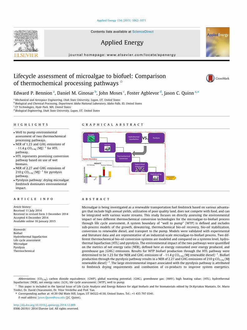
g r a p h i c a l a b s t r a c t
Growth
Harvest
Thermochemical Conversion
Supercri�cal Stabiliza�on
Hydrotrea�ng
Renewable Diesel
Hydrothermal Liquefac�on
Pyrolysis vs.
System Boundary
Glo
bal W
arm
ing
Pote
n�al
HTL Pathway Pyrolysis Pathway RESULTS
a r t i c l e i n f o
Article history:Received 11 July 2014Received in revised form 3 December 2014Accepted 4 December 2014Available online 16 January 2015
Keywords:BiofuelHydrothermal liquefactionLife cycle assessmentMicroalgaePyrolysisThermochemical
a b s t r a c t
Microalgae is being investigated as a renewable transportation fuel feedstock based on various advanta-ges that include high annual yields, utilization of poor quality land, does not compete with food, and canbe integrated with various waste streams. This study focuses on directly assessing the environmentalimpact of two different thermochemical conversion technologies for the microalgae-to-biofuel processthrough life cycle assessment. A system boundary of ‘‘well to pump’’ (WTP) is defined and includessub-process models of the growth, dewatering, thermochemical bio-oil recovery, bio-oil stabilization,conversion to renewable diesel, and transport to the pump. Models were validated with experimentaland literature data and are representative of an industrial-scale microalgae-to-biofuel process. Two dif-ferent thermochemical bio-oil conversion systems are modeled and compared on a systems level, hydro-thermal liquefaction (HTL) and pyrolysis. The environmental impact of the two pathways were quantifiedon the metrics of net energy ratio (NER), defined here as energy consumed over energy produced, andgreenhouse gas (GHG) emissions. Results for WTP biofuel production through the HTL pathway weredetermined to be 1.23 for the NER and GHG emissions of �11.4 g CO2-eq (MJ renewable diesel)�1. Biofuelproduction through the pyrolysis pathway results in a NER of 2.27 and GHG emissions of 210 g CO2-eq (MJrenewable diesel)�1. The large environmental impact associated with the pyrolysis pathway is attributedto feedstock drying requirements and combustion of co-products to improve system energetics.
othermal
r. Mario
E.P. Bennion et al. / Applied Energy 154 (2015) 1062–1071 1063
Discussion focuses on a detailed breakdown of the overall process energetics and GHGs, impact of mod-eling at laboratory-scale compared to industrial-scale, environmental impact sensitivity to systems engi-neering input parameters for future focused research and development, and a comparison of results toliterature.
� 2014 Elsevier Ltd. All rights reserved.
1. Introduction
The current increase in global energy demand, as well as thenegative impact petroleum based energy sources are having onthe environment, has led to a renewed interest in renewableenergy resources. A variety of third generation feedstocks for bio-fuel production are being investigated as viable alternatives to tra-ditional energy sources including microalgae based on inherentadvantages, specifically characteristically high lipid yields, utiliza-tion of poor quality land and water, and integration with pointsource carbon dioxide sources such as coal fired power plants.Efforts to advance the commercial feasibility of microalgae basedbiofuels have focused on improvements to the various processingsteps associated with the production of feedstock through to fuels.Life cycle assessment (LCA) has emerged as a foundational tool inevaluating alternative processing technologies with results usedto highlight areas for further research and development. Variousconversion technologies have been identified but the overallimpact of the technologies must be understood on a systems level.
In the microalgae to biofuels system there are a variety of con-version technologies being explored in an effort to move towardcommercialization. Various technologies have emerged as viableoptions for the extraction and conversion of biomass to biocrudeincluding but not limited to pyrolysis, hydrothermal liquefaction(HTL), and lipid extraction. Two thermochemical technologies,HTL and pyrolysis, have both been experimentally demonstratedto be viable processes for the conversion of microalgae to bio-oil.Both technologies having the benefit of thermochemically convert-ing non-lipid microalgae constituents into a bio-oil. The HTL con-version process has been demonstrated with a microalgae slurry(microalgae and water mixture), which has the benefit of decreas-ing the energy requirements for water removal [1–20]. Bio-oilrecovery through pyrolysis has proven to an effective technologywith feedstocks such as woody biomass with limited work on mic-roalgae [2,21–24]. A challenge that arises with a microalgae feed-stock is pyrolysis requires a relatively dry feedstock, 15–20%moisture [25,26]. Removal of water to this moisture contentrequires substantial energy for a microalgae feedstock. Both HTLand pyrolysis have been demonstrated to be feasible with limitedassessment on the industrial-scale feasibility of the technologiesbased on environmental impact [27,28].
LCA has become a premier tool in assessing process energeticsand environmental impacts of biofuels production systems. LCAsreported for the microalgae to biofuels process incorporating vari-ous conversion technologies have been performed with resultsvarying dramatically due to simplistic process models, differencesin production pathways, and incomplete system boundaries[1,3,27–58]. The majority of the studies have focused on traditionlipid extraction systems [30,32,33,39,42,43,46,50–53,55–57,59]. Alimited number of studies have evaluated thermochemical conver-sion technologies on the metrics of net energy and greenhouse gas(GHG) emissions [1,27,28,34,60]. Frank et al. [34] examined theenvironmental impact of an HTL process with a well to pump(WTP) system boundary, but includes an additional processing ofHTL byproducts to biogas. de Boer et al. [1] evaluates HTL as aconversion system but fails to include microalgae growth,
downstream processing of bio-oil, and HTL byproducts in the anal-ysis. An alternative thermochemical processing technology, pyro-lysis, has received minimal evaluation [27]. A LCA was carriedout by Grierson et al. [27] for a WTP system boundary with thegrowth system based on a photobioreactor architecture and spraydrying for water removal. These processes are accepted in industry,but are not representative of optimized industrial function. A directcomparison of the energetics of microalgae bio-oil recoverythrough pyrolysis and HTL has been performed but exclusion ofupstream and downstream processing limits the use of resultsfor the comparison to other production pathways [2,27]. Forassessing the thermochemical conversion of microalgae biomassthrough pyrolysis or HTL and directly comparing results to othertechnologies a LCA that accounts for all energy and GHG contribu-tions in a WTP system boundary is required.
Based on the current state of the field there exists a need for theevaluation and comparison of the environmental impact of ther-mochemical processing technologies applied to the microalgae tobiofuels process on a systems level. A modular systems engineer-ing model was constructed including growth, dewatering, bio-oilrecovery through HTL or pyrolysis, bio-oil stabilization, bio-oil con-version to renewable diesel, and transport and distribution to con-sumer pumps to define a system boundary of WTP and validatedwith experimental and literature data. Two system models weredeveloped: (1) a small-scale model representative of the operationof the experimental systems and (2) an industrial-scale model, val-idated through experimental and literature data, to assess facilityfunction at commercial scale. All-sub process models were vali-dated with experimental data and integrated into a system modelrepresentative of the microalgae to biofuel production process. Lit-erature data was limited to promising growth and dewateringtechniques and bio-oil upgrading in the industrial-scale systemwith experimental data used for HTL and pyrolysis performance.Environmental impact results are presented on the metrics of netenergy ratio (NER) and GHG emissions with sub-processing resolu-tion. Discussion focuses on the impact of modeling at industrial-scale, sensitivity to process parameters, and a comparison ofresults to other conversion technologies based on publishedliterature.
2. Methods
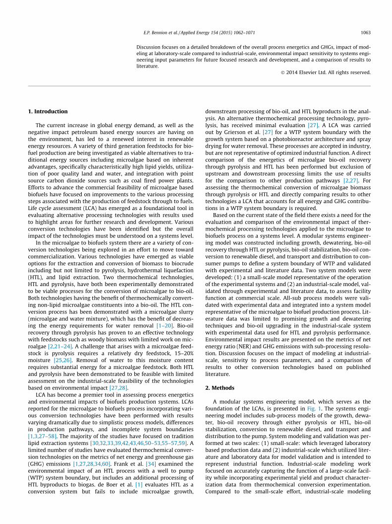
A modular systems engineering model, which serves as thefoundation of the LCAs, is presented in Fig. 1. The systems engi-neering model includes sub-process models of the growth, dewa-ter, bio-oil recovery through either pyrolysis or HTL, bio-oilstabilization, conversion to renewable diesel, and transport anddistribution to the pump. System modeling and validation was per-formed at two scales: (1) small-scale: which leveraged laboratorybased production data and (2) industrial-scale which utilized liter-ature and laboratory data for model validation and is intended torepresent industrial function. Industrial-scale modeling workfocused on accurately capturing the function of a large-scale facil-ity while incorporating experimental yield and product character-ization data from thermochemical conversion experimentation.Compared to the small-scale effort, industrial-scale modeling
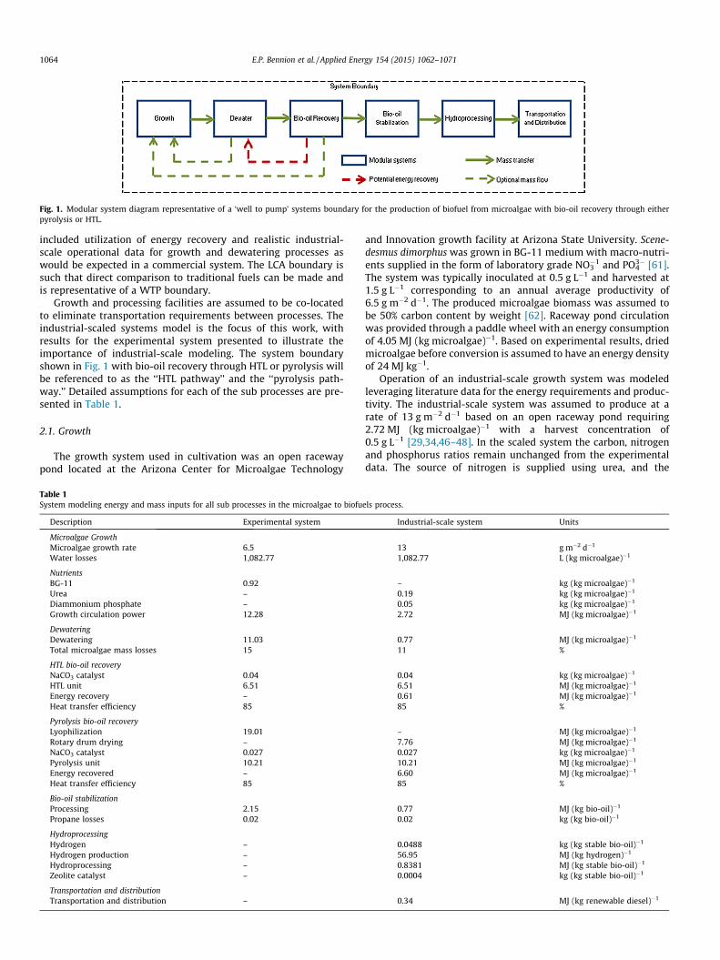
Fig. 1. Modular system diagram representative of a ‘well to pump’ systems boundary for the production of biofuel from microalgae with bio-oil recovery through eitherpyrolysis or HTL.
1064 E.P. Bennion et al. / Applied Energy 154 (2015) 1062–1071
included utilization of energy recovery and realistic industrial-scale operational data for growth and dewatering processes aswould be expected in a commercial system. The LCA boundary issuch that direct comparison to traditional fuels can be made andis representative of a WTP boundary.
Growth and processing facilities are assumed to be co-locatedto eliminate transportation requirements between processes. Theindustrial-scaled systems model is the focus of this work, withresults for the experimental system presented to illustrate theimportance of industrial-scale modeling. The system boundaryshown in Fig. 1 with bio-oil recovery through HTL or pyrolysis willbe referenced to as the ‘‘HTL pathway’’ and the ‘‘pyrolysis path-way.’’ Detailed assumptions for each of the sub processes are pre-sented in Table 1.
2.1. Growth
The growth system used in cultivation was an open racewaypond located at the Arizona Center for Microalgae Technology
Table 1System modeling energy and mass inputs for all sub processes in the microalgae to biofu
Description Experimental system
Microalgae GrowthMicroalgae growth rate 6.5Water losses 1,082.77
NutrientsBG-11 0.92Urea –Diammonium phosphate –Growth circulation power 12.28
DewateringDewatering 11.03Total microalgae mass losses 15
HTL bio-oil recoveryNaCO3 catalyst 0.04HTL unit 6.51Energy recovery –Heat transfer efficiency 85
Pyrolysis bio-oil recoveryLyophilization 19.01Rotary drum drying –NaCO3 catalyst 0.027Pyrolysis unit 10.21Energy recovered –Heat transfer efficiency 85
Bio-oil stabilizationProcessing 2.15Propane losses 0.02
HydroprocessingHydrogen –Hydrogen production –Hydroprocessing –Zeolite catalyst –
Transportation and distributionTransportation and distribution –
and Innovation growth facility at Arizona State University. Scene-desmus dimorphus was grown in BG-11 medium with macro-nutri-ents supplied in the form of laboratory grade NO3
�1 and PO43� [61].
The system was typically inoculated at 0.5 g L�1 and harvested at1.5 g L�1 corresponding to an annual average productivity of6.5 g m�2 d�1. The produced microalgae biomass was assumed tobe 50% carbon content by weight [62]. Raceway pond circulationwas provided through a paddle wheel with an energy consumptionof 4.05 MJ (kg microalgae)�1. Based on experimental results, driedmicroalgae before conversion is assumed to have an energy densityof 24 MJ kg�1.
Operation of an industrial-scale growth system was modeledleveraging literature data for the energy requirements and produc-tivity. The industrial-scale system was assumed to produce at arate of 13 g m�2 d�1 based on an open raceway pond requiring2.72 MJ (kg microalgae)�1 with a harvest concentration of0.5 g L�1 [29,34,46–48]. In the scaled system the carbon, nitrogenand phosphorus ratios remain unchanged from the experimentaldata. The source of nitrogen is supplied using urea, and the
els process.
Industrial-scale system Units
13 g m�2 d�1
1,082.77 L (kg microalgae)�1
– kg (kg microalgae)�1
0.19 kg (kg microalgae)�1
0.05 kg (kg microalgae)�1
2.72 MJ (kg microalgae)�1
0.77 MJ (kg microalgae)�1
11 %
0.04 kg (kg microalgae)�1
6.51 MJ (kg microalgae)�1
0.61 MJ (kg microalgae)�1
85 %
– MJ (kg microalgae)�1
7.76 MJ (kg microalgae)�1
0.027 kg (kg microalgae)�1
10.21 MJ (kg microalgae)�1
6.60 MJ (kg microalgae)�1
85 %
0.77 MJ (kg bio-oil)�1
0.02 kg (kg bio-oil)�1
0.0488 kg (kg stable bio-oil)�1
56.95 MJ (kg hydrogen)�1
0.8381 MJ (kg stable bio-oil)�1
0.0004 kg (kg stable bio-oil)�1
0.34 MJ (kg renewable diesel)�1
E.P. Bennion et al. / Applied Energy 154 (2015) 1062–1071 1065
phosphorus is supplied through diammonium phosphate as thesesources represent economically viable nutrient sources with exper-imental data supporting microalgae growth on these sources[50,63]. Carbon dioxide is supplied through co-location with anindustrial point source, such as coal derived flue gas [64].
2.2. Dewatering
The algal concentration after growth in the open raceway pondrequires water removal before the biomass can be further pro-cessed. In the experimental system excess water was removedusing a membrane filtration system which increased the algalconcentration from the harvest density of 1.5 g L�1 to 40 g L�1. Acentrifuge was then used to increase the algal concentration to220 g L�1. This concentration is adequate for bio-oil recoverythrough HTL, but further water must be removed for bio-oil recov-ery through pyrolysis. In the small-scale experimental system thiswas done through lyophilizing. Microalgae mass losses in thedewatering sub-process for the experimental system was modeledat 15%.
Industrial-scale system modeling of the dewater system wasbased on the use of a preliminary bio-flocculation system, usedto increase the algal concentration from 0.5 g L�1 to 10 g L�1, fol-lowed by dissolved air flotation, to increase algal concentrationto 15 g L�1 and finally a centrifuge for a final concentration of240 g L�1 [34,49]. The centrifuge energy requirements and perfor-mance is based on an Evodos type 10 centrifuge [65]. A final con-centration of approximately 20% solids is adequate for bio-oilrecovery of microalgae to bio-oil through HTL. For pyrolysis furtherdewatering was achieved with a rotary drum, which is detailed inthe pyrolysis sub process section. Microalgae mass losses throughthe dewatering process from bio flocculation through centrifuga-tion are approximately 11%.
2.3. Hydrothermal liquefaction (HTL)
HTL has been demonstrated to effectively convert wet, 20% sol-ids, microalgae feedstock into bio-oil [2,28,34,66]. Batch experi-mental data was collected on a reactor operated at 310 �C and10,500 kPa with a zeolite catalyst. Products from the HTL bio-oilrecovery process include bio-oil, solids, gasses, and an aqueousphase with experimental yields by mass of 37%, 16%, 30% and17% determined respectively.
The industrial-scaled system is assumed to be an optimizedprocess in terms of energy recovery with yields based on theexperimental data. Energy is recovered through the burning of pro-cess gasses used to provide heat to the reactor, and through thebio-oil stream using a heat exchanger, which transfers heat tothe incoming feed stream with an efficacy of 85%. A process flowof the modeled industrial-scale HTL system is presented in Fig. 2.The aqueous phase contains organic carbon, ammonium, and
Fig. 2. Modular system flow diagram for indu
phosphite which are used to supplement the nutrient demandsin microalgae growth. The catalyst and solids are separated fromthe oil through a centrifuge and reused.
The energetics of the HTL process are dominated by the energyrequired to heat the reactor, 6.51 MJ (kg microalgae)�1. This isslightly supplemented in the industrial-scale process, 0.61 MJ(kg microalgae)�1, by the implementation of heat recovery andburning of process gasses. The bio-oil and gasses produced throughHTL were experimentally determined to have a high heating value(HHV) of 34 MJ kg�1 and 1.1 MJ kg�1 respectively.
2.4. Pyrolysis
Bio-oil recovery from biomass through pyrolysis has beenshown to be an energetically favorable process with feedstockssuch as switchgrass, soybeans, and wood [67]. A challenge associ-ated with the pyrolysis of algal biomass is the removal of excesswater. The microalgae slurry after the dewatering process is 24%solids and must be further dewatered to 80% solids prior to pyro-lysis processing. In the experimental small-scale model microalgaewas dried using lyophilization, 19 MJ (kg microalgae)�1, and fedinto the pyrolysis reactor at 1000 g hr�1 operated with a zeolitecatalyst consumed at a rate of 27 mg (kg microalgae)�1. In thereactor the microalgae feed, gas, and catalyst are heated to400 �C and converted into a gas mixture. The gas mixture is thenfiltered, and cooled before being feed into an electrostatic precipi-tator where the bio-oil and excess gasses are collected. Productsfrom the pyrolysis process were determined experimentally withmass yields of 29.3%, 13.6%, 34.3%, and 22.9% for the bio-oil, char,gasses, and an aqueous phase, respectively.
The small-scale experimental results were leveraged for valida-tion of the yield of the industrial-scaled system. Rotary kiln dryingoperated with natural gas, with an efficiency of 85% [68], was usedin the industrial-scale system to drive off the excess water beforepyrolyzing the biomass as it represents an efficient and commer-cially demonstrated technology [69]. In the industrial-scale sys-tem, the pyrolysis reactor energy is supplemented throughintersystem energy recovery and combustion of by-products, charand gasses, with HHVs of 25.4 MJ kg�1 and 7.3 MJ kg�1, respec-tively. A portion of the process gasses are compressed and recycledback into the reactor to maintain an oxygen deprived system. Afterthe pyrolysis process, product gasses from the reactor are filteredand heat is recovered through a heat exchanger with an 85% effi-cacy. The recovered heat is used to preheat the gas and microalgaemixture as it enters the reactor. A diagram of the industrial-scalesystem with energy recovery pathways is presented in Fig. 3.
The pyrolysis sub-process energetic inputs are dominated bythe reactor, 7.9 MJ (kg microalgae)�1, and the drying requirements,7.8 MJ (kg microalgae)�1. Burning of process byproducts are usedto supplement the sub-process energetics, supplying 6.6 MJ
strial-scale HTL bio-oil recovery process.
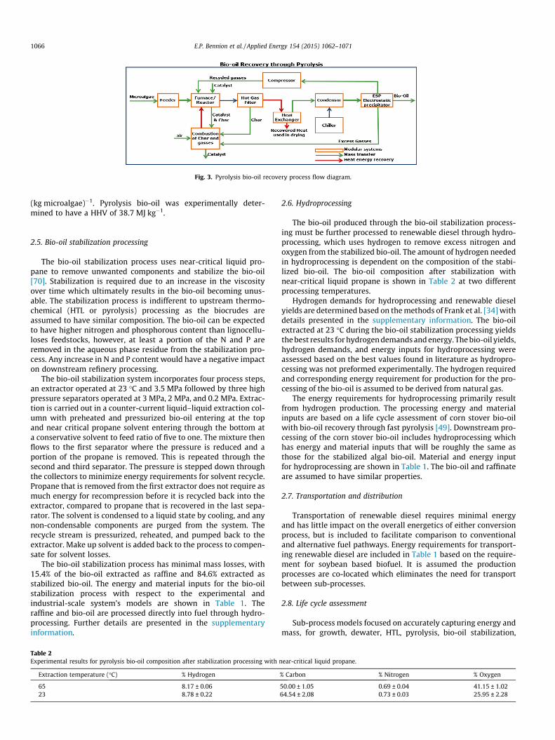
Fig. 3. Pyrolysis bio-oil recovery process flow diagram.
1066 E.P. Bennion et al. / Applied Energy 154 (2015) 1062–1071
(kg microalgae)�1. Pyrolysis bio-oil was experimentally deter-mined to have a HHV of 38.7 MJ kg�1.
2.5. Bio-oil stabilization processing
The bio-oil stabilization process uses near-critical liquid pro-pane to remove unwanted components and stabilize the bio-oil[70]. Stabilization is required due to an increase in the viscosityover time which ultimately results in the bio-oil becoming unus-able. The stabilization process is indifferent to upstream thermo-chemical (HTL or pyrolysis) processing as the biocrudes areassumed to have similar composition. The bio-oil can be expectedto have higher nitrogen and phosphorous content than lignocellu-loses feedstocks, however, at least a portion of the N and P areremoved in the aqueous phase residue from the stabilization pro-cess. Any increase in N and P content would have a negative impacton downstream refinery processing.
The bio-oil stabilization system incorporates four process steps,an extractor operated at 23 �C and 3.5 MPa followed by three highpressure separators operated at 3 MPa, 2 MPa, and 0.2 MPa. Extrac-tion is carried out in a counter-current liquid–liquid extraction col-umn with preheated and pressurized bio-oil entering at the topand near critical propane solvent entering through the bottom ata conservative solvent to feed ratio of five to one. The mixture thenflows to the first separator where the pressure is reduced and aportion of the propane is removed. This is repeated through thesecond and third separator. The pressure is stepped down throughthe collectors to minimize energy requirements for solvent recycle.Propane that is removed from the first extractor does not require asmuch energy for recompression before it is recycled back into theextractor, compared to propane that is recovered in the last sepa-rator. The solvent is condensed to a liquid state by cooling, and anynon-condensable components are purged from the system. Therecycle stream is pressurized, reheated, and pumped back to theextractor. Make up solvent is added back to the process to compen-sate for solvent losses.
The bio-oil stabilization process has minimal mass losses, with15.4% of the bio-oil extracted as raffine and 84.6% extracted asstabilized bio-oil. The energy and material inputs for the bio-oilstabilization process with respect to the experimental andindustrial-scale system’s models are shown in Table 1. Theraffine and bio-oil are processed directly into fuel through hydro-processing. Further details are presented in the supplementaryinformation.
Table 2Experimental results for pyrolysis bio-oil composition after stabilization processing with n
Extraction temperature (�C) % Hydrogen
65 8.17 ± 0.0623 8.78 ± 0.22
2.6. Hydroprocessing
The bio-oil produced through the bio-oil stabilization process-ing must be further processed to renewable diesel through hydro-processing, which uses hydrogen to remove excess nitrogen andoxygen from the stabilized bio-oil. The amount of hydrogen neededin hydroprocessing is dependent on the composition of the stabi-lized bio-oil. The bio-oil composition after stabilization withnear-critical liquid propane is shown in Table 2 at two differentprocessing temperatures.
Hydrogen demands for hydroprocessing and renewable dieselyields are determined based on the methods of Frank et al. [34] withdetails presented in the supplementary information. The bio-oilextracted at 23 �C during the bio-oil stabilization processing yieldsthe best results for hydrogen demands and energy. The bio-oil yields,hydrogen demands, and energy inputs for hydroprocessing wereassessed based on the best values found in literature as hydropro-cessing was not preformed experimentally. The hydrogen requiredand corresponding energy requirement for production for the pro-cessing of the bio-oil is assumed to be derived from natural gas.
The energy requirements for hydroprocessing primarily resultfrom hydrogen production. The processing energy and materialinputs are based on a life cycle assessment of corn stover bio-oilwith bio-oil recovery through fast pyrolysis [49]. Downstream pro-cessing of the corn stover bio-oil includes hydroprocessing whichhas energy and material inputs that will be roughly the same asthose for the stabilized algal bio-oil. Material and energy inputfor hydroprocessing are shown in Table 1. The bio-oil and raffinateare assumed to have similar properties.
2.7. Transportation and distribution
Transportation of renewable diesel requires minimal energyand has little impact on the overall energetics of either conversionprocess, but is included to facilitate comparison to conventionaland alternative fuel pathways. Energy requirements for transport-ing renewable diesel are included in Table 1 based on the require-ment for soybean based biofuel. It is assumed the productionprocesses are co-located which eliminates the need for transportbetween sub-processes.
2.8. Life cycle assessment
Sub-process models focused on accurately capturing energy andmass, for growth, dewater, HTL, pyrolysis, bio-oil stabilization,
ear-critical liquid propane.
% Carbon % Nitrogen % Oxygen
50.00 ± 1.05 0.69 ± 0.04 41.15 ± 1.0264.54 ± 2.08 0.73 ± 0.03 25.95 ± 2.28

0
1
2
3
4
5
6
7
ExperimentalSystem
Industrial ScaledSystem
ExperimentalSystem
Industrial ScaledSystem
LTHsisyloryP
NER
(MJ i
nput
(MJ R
enew
able
Die
sel)-1
)
Transporta�on and Distribu�onHydroprocessingBio-oil Stabiliza�onBio-oil RecoveryDryingGrowth and Dewatering
Fig. 4. Net energy ratio (NER) results for microalgae to renewable diesel with bio-oil recovery through pyrolysis or HTL for small-scale experimental system and theindustrial-scaled system.
E.P. Bennion et al. / Applied Energy 154 (2015) 1062–1071 1067
hydroprocessing, and transportation and distribution were inte-grated into an engineering system model and serves as the back-bone for the LCA. Outputs from the engineering system modelserve as the inputs to the LCA modeling. Life cycle inventory(LCI) data was obtained from GREET 2013 and the United StatesEnvironmental Protection Agency [71,72]. The pathways modeledare assessed on two metrics, NER and global warming potential(GWP). NER is leveraged as an indicator of the overall energeticeffectiveness of the process, Eq. (1). A NER of less than 1 is desir-able with the current NER for conventional petroleum diesel at0.18 [39].
NER ¼ Energy inputEnergy out in biodiesel
ð1Þ
The GWP is assessed through the environmental impacts associatedwith carbon dioxide, methane, and dinitrogen oxide. The threeemissions are combined into a carbon dioxide equivalence(CO2-eq) based on a 100 year GWP of 1, 25, and 298, for carbon diox-ide, methane, and dinitrogen oxide, respectively [73]. GWP isdetailed for the WTP system boundary of the industrial-scale sys-tem for each of the two thermochemical conversion technologypathways modeled. Emissions were separated into three categories:(1) emissions from electrical energy consumption, (2) emissionsfrom production of process heat, and (3) material product consump-tion. Emissions from product consumption are a result of nutrientdemands, system losses, such as losses in catalyst, and burning ofprocess byproducts, such as char and pyrolysis gasses.
3. Results and discussion
Modular systems engineering models of the microalgae tobiofuel process were leveraged to perform a LCA of two differentthermochemical conversion pathways at two different scales,small- and industrial-scale. The small-scale system is based onthe experimental systems used for process demonstration andevaluation. The industrial-scaled system is representative of indus-trial function through the inclusion of energy recovery throughtechniques previously discussed, system optimization, and sub-process co-location, and includes experimental results in termsof defining pyrolysis and HTL function.
3.1. Net energy, and greenhouse gas emissions
The NER results for the two different thermochemical process-ing pathways and modeling scales are broken down by sub-processand presented in Fig. 4. The importance of modeling industrial-scale is illustrated in the large difference in NER results for bothpathways. The NER for the HTL pathway and pyrolysis pathwayare improved by factors of 2.4 and 2.9, respectively, between thesmall- and industrial-scale modeling efforts. The overall processNER results from the industrial-scale system modeling for HTLand pyrolysis pathways are 1.24 and 2.28, and represent energeti-cally unfavorable systems. In comparison with the NERs of otherenergy fuels the WTP NERs for conventional diesel, corn ethanol,and soy based biodiesel are 0.18, 1.07, and 0.80, respectively[39,74].
The energy and material requirements for growth, dewatering,stabilization and hydroprocessing are the same for both pathwaysevaluated. Slight differences in the sub-process NERs between thetwo conversion pathways are the result of differences in bio-oilrecovery, oil yields, and heating values as these directly affectthe functional units. At the industrial-scale, the HTL pathway hasa higher mass yield, 37%, as compared to the pyrolysis pathway,29%. Experimental data showed the HHV in the pyrolysis was11% higher than that of the HTL oil. However, the higher bio-oil
yield achieved with HTL processing compensates for the lowerbio-oil energy density.
The results from this study show HTL to be favorable comparedto pyrolysis on a system level primarily due to the integration witha wet microalgae slurry (20% solids), whereas pyrolysis requiresdried microalgae (80% solids). The dewater requirements toachieve the percent solids required for HTL conversion facilitatesthe use of bio-flocculation, dissolved air filtration and a centrifugefor removal of water. The pyrolysis pathway requires the remain-ing water to be removed through thermal methods. Drying of mic-roalgae requires substantial energy, accounting for nearly half(0.97) of the overall NER for the industrial-scale pyrolysis pathway.
The energy flow for the HTL bio-oil recovery processes normal-ized to 1 unit of energy for the industrial-scale modeling efforts isshown in Fig. 5(A). The HTL process is 55% efficient in the conver-sion of embodied feedstock energy to bio-oil. An additional 5.6% ofthe sub-process energy is recovered through a heat exchanger andburning of HTL gasses and recycled internally to minimize energyinputs.
Comparatively, the pyrolysis sub-process is 51% efficient in theconversion of embodied feedstock energy to bio-oil, Fig. 5(B). Thepyrolysis sub-process is integrated into a bio-refinery systemallowing for energy recovery through a heat exchanger and com-bustion of pyrolysis byproducts, char and gasses. Recovered energyaccounts for 28% of the embodied energy in the feedstock, and isused to supplement the energy demand of the drying unit andheating demands in the reactor. Recovered energy helps the overallenergetics of the system, but does not negate the energy demandsfor drying the microalgae biomass or heating in the reactor. Evenwith energy recovery the combination of the energy demands inthe drying unit and pyrolysis reactor are too large for microalgaeconversion through pyrolysis to be made energetically favorable.
3.2. Global warming potential
GHG emissions are detailed for the WTP system boundary of theindustrial-scale systems for the two thermochemical conversiontechnologies modeled and compared to conventional diesel, andsoybean based biodiesel, Fig. 6. The emissions are broken downinto process emissions for electrical, heating, and product con-sumption. Emissions from product consumption are a result ofnutrient demands, material losses, and burning of process byprod-ucts, such as char and pyrolysis or HTL gasses. Extending theboundary to well to wheel (WTW) requires the emissions from
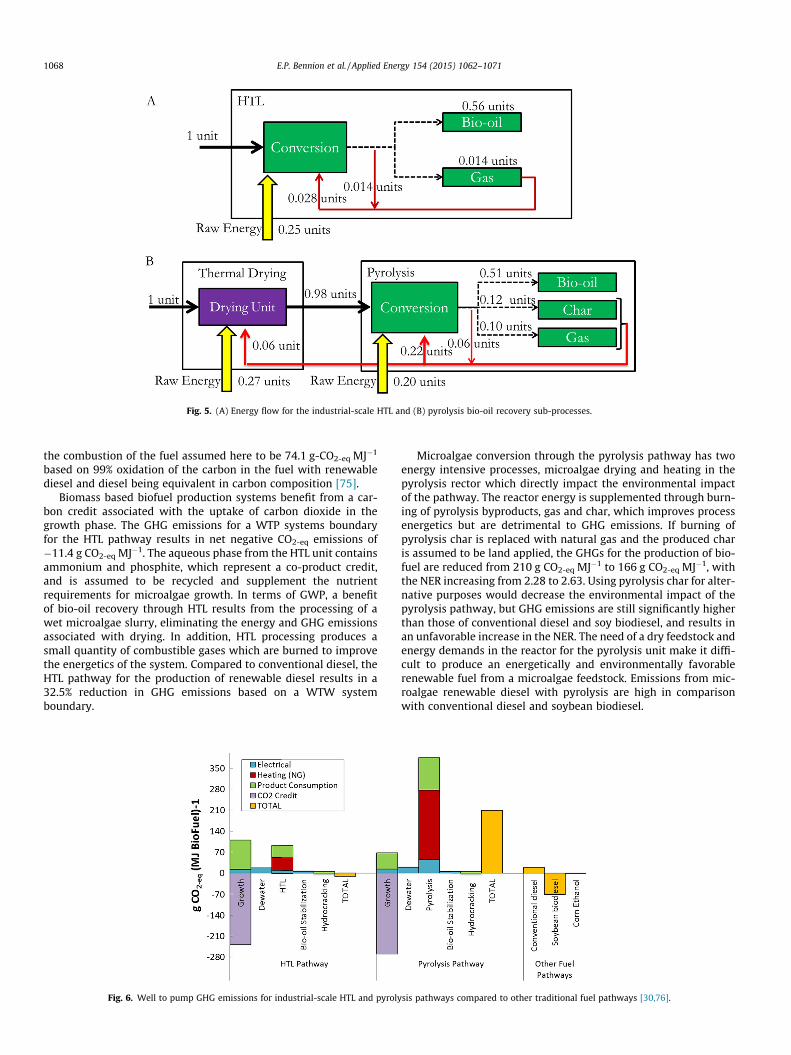
Fig. 5. (A) Energy flow for the industrial-scale HTL and (B) pyrolysis bio-oil recovery sub-processes.
1068 E.P. Bennion et al. / Applied Energy 154 (2015) 1062–1071
the combustion of the fuel assumed here to be 74.1 g-CO2-eq MJ�1
based on 99% oxidation of the carbon in the fuel with renewablediesel and diesel being equivalent in carbon composition [75].
Biomass based biofuel production systems benefit from a car-bon credit associated with the uptake of carbon dioxide in thegrowth phase. The GHG emissions for a WTP systems boundaryfor the HTL pathway results in net negative CO2-eq emissions of�11.4 g CO2-eq MJ�1. The aqueous phase from the HTL unit containsammonium and phosphite, which represent a co-product credit,and is assumed to be recycled and supplement the nutrientrequirements for microalgae growth. In terms of GWP, a benefitof bio-oil recovery through HTL results from the processing of awet microalgae slurry, eliminating the energy and GHG emissionsassociated with drying. In addition, HTL processing produces asmall quantity of combustible gases which are burned to improvethe energetics of the system. Compared to conventional diesel, theHTL pathway for the production of renewable diesel results in a32.5% reduction in GHG emissions based on a WTW systemboundary.
Fig. 6. Well to pump GHG emissions for industrial-scale HTL and pyroly
Microalgae conversion through the pyrolysis pathway has twoenergy intensive processes, microalgae drying and heating in thepyrolysis rector which directly impact the environmental impactof the pathway. The reactor energy is supplemented through burn-ing of pyrolysis byproducts, gas and char, which improves processenergetics but are detrimental to GHG emissions. If burning ofpyrolysis char is replaced with natural gas and the produced charis assumed to be land applied, the GHGs for the production of bio-fuel are reduced from 210 g CO2-eq MJ�1 to 166 g CO2-eq MJ�1, withthe NER increasing from 2.28 to 2.63. Using pyrolysis char for alter-native purposes would decrease the environmental impact of thepyrolysis pathway, but GHG emissions are still significantly higherthan those of conventional diesel and soy biodiesel, and results inan unfavorable increase in the NER. The need of a dry feedstock andenergy demands in the reactor for the pyrolysis unit make it diffi-cult to produce an energetically and environmentally favorablerenewable fuel from a microalgae feedstock. Emissions from mic-roalgae renewable diesel with pyrolysis are high in comparisonwith conventional diesel and soybean biodiesel.
sis pathways compared to other traditional fuel pathways [30,76].
E.P. Bennion et al. / Applied Energy 154 (2015) 1062–1071 1069
3.3. Sensitivity analysis
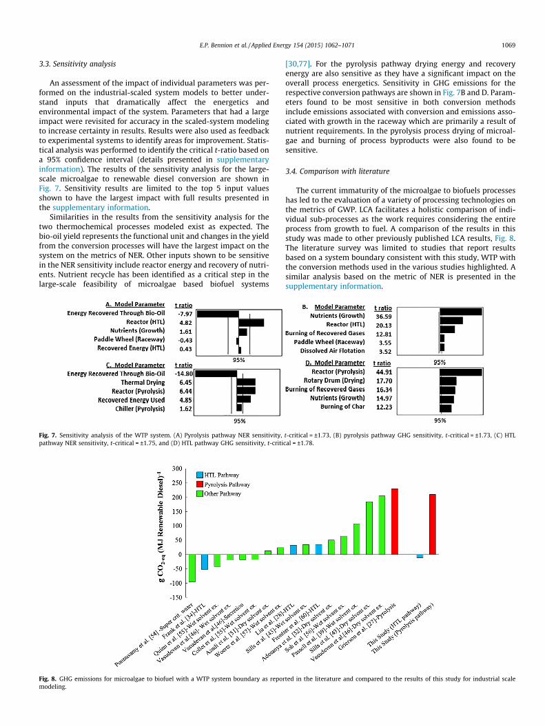
An assessment of the impact of individual parameters was per-formed on the industrial-scaled system models to better under-stand inputs that dramatically affect the energetics andenvironmental impact of the system. Parameters that had a largeimpact were revisited for accuracy in the scaled-system modelingto increase certainty in results. Results were also used as feedbackto experimental systems to identify areas for improvement. Statis-tical analysis was performed to identify the critical t-ratio based ona 95% confidence interval (details presented in supplementaryinformation). The results of the sensitivity analysis for the large-scale microalgae to renewable diesel conversion are shown inFig. 7. Sensitivity results are limited to the top 5 input valuesshown to have the largest impact with full results presented inthe supplementary information.
Similarities in the results from the sensitivity analysis for thetwo thermochemical processes modeled exist as expected. Thebio-oil yield represents the functional unit and changes in the yieldfrom the conversion processes will have the largest impact on thesystem on the metrics of NER. Other inputs shown to be sensitivein the NER sensitivity include reactor energy and recovery of nutri-ents. Nutrient recycle has been identified as a critical step in thelarge-scale feasibility of microalgae based biofuel systems
Fig. 7. Sensitivity analysis of the WTP system. (A) Pyrolysis pathway NER sensitivity,pathway NER sensitivity, t-critical = ±1.75, and (D) HTL pathway GHG sensitivity, t-criti
Fig. 8. GHG emissions for microalgae to biofuel with a WTP system boundary as repormodeling.
[30,77]. For the pyrolysis pathway drying energy and recoveryenergy are also sensitive as they have a significant impact on theoverall process energetics. Sensitivity in GHG emissions for therespective conversion pathways are shown in Fig. 7B and D. Param-eters found to be most sensitive in both conversion methodsinclude emissions associated with conversion and emissions asso-ciated with growth in the raceway which are primarily a result ofnutrient requirements. In the pyrolysis process drying of microal-gae and burning of process byproducts were also found to besensitive.
3.4. Comparison with literature
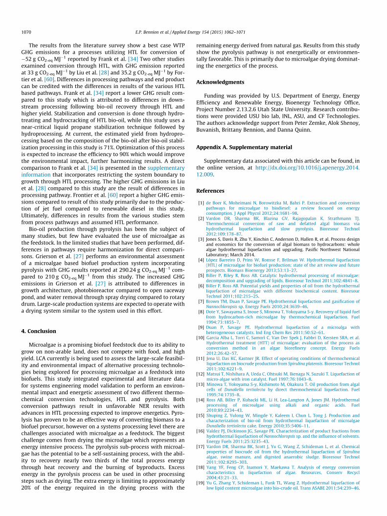
The current immaturity of the microalgae to biofuels processeshas led to the evaluation of a variety of processing technologies onthe metrics of GWP. LCA facilitates a holistic comparison of indi-vidual sub-processes as the work requires considering the entireprocess from growth to fuel. A comparison of the results in thisstudy was made to other previously published LCA results, Fig. 8.The literature survey was limited to studies that report resultsbased on a system boundary consistent with this study, WTP withthe conversion methods used in the various studies highlighted. Asimilar analysis based on the metric of NER is presented in thesupplementary information.
t-critical = ±1.73, (B) pyrolysis pathway GHG sensitivity, t-critical = ±1.73, (C) HTLcal = ±1.78.
ted in the literature and compared to the results of this study for industrial scale
1070 E.P. Bennion et al. / Applied Energy 154 (2015) 1062–1071
The results from the literature survey show a best case WTPGHG emissions for a processes utilizing HTL for conversion of�52 g CO2-eq MJ�1 reported by Frank et al. [34] Two other studiesexamined conversion through HTL, with GHG emission reportedat 33 g CO2-eq MJ�1 by Liu et al. [28] and 35.2 g CO2-eq MJ�1 by For-tier et al. [60]. Differences in processing pathways and end productcan be credited with the differences in results of the various HTLbased pathways. Frank et al. [34] report a lower GHG result com-pared to this study which is attributed to differences in down-stream processing following bio-oil recovery through HTL andhigher yield. Stabilization and conversion is done through hydro-treating and hydrocracking of HTL bio-oil, while this study uses anear-critical liquid propane stabilization technique followed byhydroprocessing. At current, the estimated yield from hydropro-cessing based on the composition of the bio-oil after bio-oil stabil-ization processing in this study is 71%. Optimization of this processis expected to increase the efficiency to 90% which would improvethe environmental impact, further harmonizing results. A directcomparison to Frank et al. [34] is presented in the supplementaryinformation that incorporates restricting the system boundary togrowth through HTL processing. The higher GHG emissions in Liuet al. [28] compared to this study are the result of differences inprocessing pathway. Frontier et al. [60] report a higher GHG emis-sions compared to result of this study primarily due to the produc-tion of jet fuel compared to renewable diesel in this study.Ultimately, differences in results from the various studies stemfrom process pathways and assumed HTL performance.
Bio-oil production through pyrolysis has been the subject ofmany studies, but few have evaluated the use of microalgae asthe feedstock. In the limited studies that have been performed, dif-ferences in pathways require harmonization for direct compari-sons. Grierson et al. [27] performs an environmental assessmentof a microalgae based biofuel production system incorporatingpyrolysis with GHG results reported at 290.24 g CO2-eq MJ�1 com-pared to 210 g CO2-eq MJ�1 from this study. The increased GHGemissions in Grierson et al. [27] is attributed to differences ingrowth architecture, photobioreactor compared to open racewaypond, and water removal through spray drying compared to rotarydrum. Large-scale production systems are expected to operate witha drying system similar to the system used in this effort.
4. Conclusion
Microalgae is a promising biofuel feedstock due to its ability togrow on non-arable land, does not compete with food, and highyield. LCA currently is being used to assess the large-scale feasibil-ity and environmental impact of alternative processing technolo-gies being explored for processing microalgae as a feedstock intobiofuels. This study integrated experimental and literature datafor systems engineering model validation to perform an environ-mental impact and energetic assessment of two different thermo-chemical conversion technologies, HTL and pyrolysis. Bothconversion pathways result in unfavorable NER results withadvances in HTL processing expected to improve energetics. Pyro-lysis has proven to be an effective way of converting biomass to abiofuel precursor, however on a systems processing level there arechallenges associated with microalgae as a feedstock. The biggestchallenge comes from drying the microalgae which represents anenergy intensive process. The pyrolysis sub-process with microal-gae has the potential to be a self-sustaining process, with the abil-ity to recovery nearly two thirds of the total process energythrough heat recovery and the burning of byproducts. Excessenergy in the pyrolysis process can be used in other processingsteps such as drying. The extra energy is limiting to approximately20% of the energy required in the drying process with the
remaining energy derived from natural gas. Results from this studyshow the pyrolysis pathway is not energetically or environmen-tally favorable. This is primarily due to microalgae drying dominat-ing the energetics of the process.
Acknowledgments
Funding was provided by U.S. Department of Energy, EnergyEfficiency and Renewable Energy, Bioenergy Technology Office,Project Number 2.13.2.6 Utah State University. Research contribu-tions were provided USU bio lab, INL, ASU, and CF Technologies.The authors acknowledge support from Peter Zemke, Alok Shenoy,Buvanish, Brittany Bennion, and Danna Quinn.
Appendix A. Supplementary material
Supplementary data associated with this article can be found, inthe online version, at http://dx.doi.org/10.1016/j.apenergy.2014.12.009.
References
[1] de Boer K, Moheimani N, Borowitzka M, Bahri P. Extraction and conversionpathways for microalgae to biodiesel: a review focused on energyconsumption. J Appl Phycol 2012;24:1681–98.
[2] Vardon DR, Sharma BK, Blazina GV, Rajagopalan K, Strathmann TJ.Thermochemical conversion of raw and defatted algal biomass viahydrothermal liquefaction and slow pyrolysis. Bioresour Technol2012;109:178–87.
[3] Jones S, Davis R, Zhu Y, Kinchin C, Anderson D, Hallen R, et al. Process designand economics for the conversion of algal biomass to hydrocarbons: wholealgae hydrothermal liquefaction and upgrading. Pasific Northwest NationalLaboratory; March 2014.
[4] López Barreiro D, Prins W, Ronsse F, Brilman W. Hydrothermal liquefaction(HTL) of microalgae for biofuel production: state of the art review and futureprospects. Biomass Bioenergy 2013;53:13–27.
[5] Biller P, Riley R, Ross AB. Catalytic hydrothermal processing of microalgae:decomposition and upgrading of lipids. Bioresour Technol 2011;102:4841–8.
[6] Biller P, Ross AB. Potential yields and properties of oil from the hydrothermalliquefaction of microalgae with different biochemical content. BioresourTechnol 2011;102:215–25.
[7] Brown TM, Duan P, Savage PE. Hydrothermal liquefaction and gasification ofNannochloropsis sp. Energy Fuels 2010;24:3639–46.
[8] Dote Y, Sawayama S, Inoue S, Minowa T, Yokoyama S-y. Recovery of liquid fuelfrom hydrocarbon-rich microalgae by thermochemical liquefaction. Fuel1994;73:1855–7.
[9] Duan P, Savage PE. Hydrothermal liquefaction of a microalga withheterogeneous catalysts. Ind Eng Chem Res 2011;50:52–61.
[10] Garcia Alba L, Torri C, Samorì C, Van Der Spek J, Fabbri D, Kersten SRA, et al.Hydrothermal treatment (HTT) of microalgae: evaluation of the process asconversion method in an algae biorefinery concept. Energy Fuels2012;26:42–57.
[11] Jena U, Das KC, Kastner JR. Effect of operating conditions of thermochemicalliquefaction on biocrude production from Spirulina platensis. Bioresour Technol2011;102:6221–9.
[12] Matsui T, Nishihara A, Ueda C, Ohtsuki M, Ikenaga N, Suzuki T. Liquefaction ofmicro-algae with iron catalyst. Fuel 1997;76:1043–8.
[13] Minowa T, Yokoyama S-y, Kishimoto M, Okakura T. Oil production from algalcells of Dunaliella tertiolecta by direct thermochemical liquefaction. Fuel1995;74:1735–8.
[14] Ross AB, Biller P, Kubacki ML, Li H, Lea-Langton A, Jones JM. Hydrothermalprocessing of microalgae using alkali and organic acids. Fuel2010;89:2234–43.
[15] Shuping Z, Yulong W, Mingde Y, Kaleem I, Chun L, Tong J. Production andcharacterization of bio-oil from hydrothermal liquefaction of microalgaeDunaliella tertiolecta cake. Energy 2010;35:5406–11.
[16] Valdez PJ, Dickinson JG, Savage PE. Characterization of product fractions fromhydrothermal liquefaction of Nannochloropsis sp. and the influence of solvents.Energy Fuels 2011;25:3235–43.
[17] Vardon DR, Sharma BK, Scott J, Yu G, Wang Z, Schideman L, et al. Chemicalproperties of biocrude oil from the hydrothermal liquefaction of Spirulinaalgae, swine manure, and digested anaerobic sludge. Bioresour Technol2011;102:8295–303.
[18] Yang YF, Feng CP, Inamori Y, Maekawa T. Analysis of energy conversioncharacteristics in liquefaction of algae. Resources, Conserv Recycl2004;43:21–33.
[19] Yu G, Zhang Y, Schideman L, Funk TL, Wang Z. Hydrothermal liquefaction oflow lipid content microalgae into bio-crude oil. Trans ASABE 2011;54:239–46.
E.P. Bennion et al. / Applied Energy 154 (2015) 1062–1071 1071
[20] Zou S, Wu Y, Yang M, Li C, Tong J. Bio-oil production from sub- andsupercritical water liquefaction of microalgae Dunaliella tertiolecta and relatedproperties. Energy Environ Sci 2010;3:1073–8.
[21] Barta K, Ford PC. Catalytic conversion of nonfood woody biomass solids toorganic liquids. Acc Chem Res 2014;47:1503–12.
[22] Corbetta M, Frassoldati A, Bennadji H, Smith K, Serapiglia MJ, Gauthier G, et al.Pyrolysis of centimeter-scale woody biomass particles: kinetic modeling andexperimental validation. Energy Fuels 2014;28:3884–98.
[23] Septien S, Valin S, Dupont C, Peyrot M, Salvador S. Effect of particle size andtemperature on woody biomass fast pyrolysis at high temperature (1000–1400 �C). Fuel 2012;97:202–10.
[24] Wannapeera J, Fungtammasan B, Worasuwannarak N. Effects of temperatureand holding time during torrefaction on the pyrolysis behaviors of woodybiomass. J Anal Appl Pyrolysis 2011;92:99–105.
[25] Mohan D, Pittman CU, Steele PH. Pyrolysis of wood/biomass for bio-oil: acritical review. Energy Fuels 2006;20:848–89.
[26] Di Blasi C. Modeling chemical and physical processes of wood and biomasspyrolysis. Prog Energy Combust Sci 2008;34:47–90.
[27] Grierson S, Strezov V, Bengtsson J. Life cycle assessment of a microalgaebiomass cultivation, bio-oil extraction and pyrolysis processing regime. AlgalRes 2013;2:299–311.
[28] Liu X, Saydah B, Eranki P, Colosi LM, Greg Mitchell B, Rhodes J, et al. Pilot-scaledata provide enhanced estimates of the life cycle energy and emissions profileof algae biofuels produced via hydrothermal liquefaction. Bioresour Technol2013;148:63–71.
[29] ANL, NREL, PNNL. Renewable diesel from algal lipids: an integrated baselinefor cost, emissions, and resource potential from a harmonized model. USDepartment of Energy Biomass Program; June 2012.
[30] Batan L, Quinn J, Willson B, Bradley T. Net energy and greenhouse gas emissionevaluation of biodiesel derived from microalgae. Environ Sci Technol2010;44:7975–80.
[31] Beal CM, Hebner RE, Webber ME, Ruoff RS, Seibert AF. The energy return oninvestment for algal biocrude: results for a research production facility.Bioenergy Res 2012;5:341–62.
[32] Brentner LB, Eckelman MJ, Zimmerman JB. Combinatorial life cycle assessmentto inform process design of industrial production of algal biodiesel. Environ SciTechnol 2011;45:7060–7.
[33] Campbell PK, Beer T, Batten D. Life cycle assessment of biodiesel productionfrom microalgae in ponds. Bioresour Technol 2011;102:50–6.
[34] Frank E, Elgowainy A, Han J, Wang Z. Life cycle comparison of hydrothermalliquefaction and lipid extraction pathways to renewable diesel from algae.Mitigat Adapt Strategies Glob Change 2013;18:137–58.
[35] Jorquera O, Kiperstok A, Sales EA, Embirucu M, Ghirardi ML. Comparativeenergy life-cycle analyses of microalgal biomass production in open ponds andphotobioreactors. Bioresour Technol 2010;101:1406–13.
[36] Khoo HH, Sharratt PN, Das P, Balasubramanian RK, Naraharisetti PK, Shaik S.Life cycle energy and CO2 analysis of microalgae-to-biodiesel: preliminaryresults and comparisons. Bioresour Technol 2011;102:5800–7.
[37] Liu X, Clarens AF, Colosi LM. Algae biodiesel has potential despite inconclusiveresults to date. Bioresour Technol 2012;104:803–6.
[38] Menger-Krug E, Niederste-Hollenberg J, Hillenbrand T, Hiessl H. Integration ofmicroalgae systems at municipal wastewater treatment plants: implicationsfor energy and emission balances. Environ Sci Technol 2012;46:11505–14.
[39] Passell H, Dhaliwal H, Reno M, Wu B, Ben Amotz A, Ivry E, et al. Algae biodiesellife cycle assessment using current commercial data. J Environ Manage2013;129:03–11.
[40] Razon LF, Tan RR. Net energy analysis of the production of biodiesel and biogasfrom the microalgae: Haematococcus pluvialis and Nannochloropsis. ApplEnergy 2011;88:3507–14.
[41] Sevigné Itoiz E, Fuentes-Grünewald C, Gasol CM, Garcés E, Alacid E, Rossi S,et al. Energy balance and environmental impact analysis of marine microalgalbiomass production for biodiesel generation in a photobioreactor pilot plant.Biomass Bioenergy 2012;39:24–35.
[42] Shirvani T, Yan XY, Inderwildi OR, Edwards PP, King DA. Life cycle energy andgreenhouse gas analysis for algae-derived biodiesel. Energy Environ Sci2011;4:3773–8.
[43] Sills DL, Paramita V, Franke MJ, Johnson MC, Akabas TM, Greene CH, et al.Quantitative uncertainty analysis of life cycle assessment for algal biofuelproduction. Environ Sci Technol 2013;47:687–94.
[44] Slade R, Bauen A. Micro-algae cultivation for biofuels: cost, energy balance,environmental impacts and future prospects. Biomass Bioenergy2013;53:29–38.
[45] Soratana K, Landis AE. Evaluating industrial symbiosis and algae cultivationfrom a life cycle perspective. Bioresour Technol 2011;102:6892–901.
[46] Vasudevan V, Stratton RW, Pearlson MN, Jersey GR, Beyene AG, Weissman JC,et al. Environmental performance of algal biofuel technology options. EnvironSci Technol 2012;46:2451–9.
[47] Williams PJL, Laurens LML. Microalgae as biodiesel & biomass feedstocks:review & analysis of the biochemistry, energetics & economics. Energy EnvironSci 2010;3:554–90.
[48] Xu LX, Brilman DWF, Withag JAM, Brem G, Kersten S. Assessment of a dry anda wet route for the production of biofuels from microalgae: energy balanceanalysis. Bioresour Technol 2011;102:5113–22.
[49] Yanan Zhang GH, Robert CBrown. Life cycle assessment of the production ofhydrogen and transportation fuels from corn stover via fast pyrolysis. EnvironRes Lett 2013;8:1–13.
[50] Frank ED, Han J, Palou-Rivera I, Elgowainy A, Wang MQ. Life-cycle analysis ofalgal lipid fuels with the greet model. Oak Ridge (TN): Center forTransportation Research, Energy Systems Division, Argonne NationalLaboratory; 2011.
[51] Azadi P, Brownbridge G, Mosbach S, Smallbone A, Bhave A, Inderwildi O, et al.The carbon footprint and non-renewable energy demand of algae-derivedbiodiesel. Appl Energy 2014;113:1632–44.
[52] Adesanya VO, Cadena E, Scott SA, Smith AG. Life cycle assessment onmicroalgal biodiesel production using a hybrid cultivation system. BioresourTechnol 2014;163:343–55.
[53] Collet P, Lardon L, Hélias A, Bricout S, Lombaert-Valot I, Perrier B, et al.Biodiesel from microalgae – life cycle assessment and recommendations forpotential improvements. Renew Energy 2014;71:525–33.
[54] Ponnusamy S, Reddy HK, Muppaneni T, Downes CM, Deng S. Life cycleassessment of biodiesel production from algal bio-crude oils extracted undersubcritical water conditions. Bioresour Technol 2014;170:454–61.
[55] Quinn JC, Smith TG, Downes CM, Quinn C. Microalgae to biofuels lifecycleassessment-multiple pathway evaluation. Algal Res. 2014;4:116–22.
[56] Soh L, Montazeri M, Haznedaroglu BZ, Kelly C, Peccia J, Eckelman MJ, et al.Evaluating microalgal integrated biorefinery schemes: empirical controlledgrowth studies and life cycle assessment. Bioresour Technol 2014;151:19–27.
[57] Woertz IC, Benemann JR, Du N, Unnasch S, Mendola D, Mitchell BG, et al. Lifecycle GHG emissions from microalgal biodiesel – a CA-GREET model. EnvironSci Technol 2014;48:6060–8.
[58] Luo D, Hu Z, Choi DG, Thomas VM, Realff MJ, Chance RR. Life cycle energy andgreenhouse gas emissions for an ethanol production process based on blue-green algae. Environ Sci Technol 2011;44:8670–7.
[59] Baliga R, Powers SE. Sustainable algae biodiesel production in cold climates.Int J Chem Eng 2010;4:1–13.
[60] Fortier M-OP, Roberts GW, Stagg-Williams SM, Sturm BSM. Life cycleassessment of bio-jet fuel from hydrothermal liquefaction of microalgae.Appl Energy 2014;122:73–82.
[61] Richmond A. Handbook of microalgal culture biotechnology and appliedphycology. Oxford (UK): Blackwell Science; 2004.
[62] Chisti Y. Biodiesel from microalgae. Biotechnol Adv 2007;25:294–306.[63] Xin L, Hong-ying H, Ke G, Jia Y. Growth and nutrient removal properties of a
freshwater microalga Scenedesmus sp. Lx1 under different kinds of nitrogensources. Ecol Eng 2010;36:379–81.
[64] Quinn JC, Catton KB, Johnson S, Thomas HB. Geographical assessment ofmicroalgae biofuels potential incorporating resource availability. BioEnergyRes 2012;6:591–600.
[65] Evodos BV. Evodos type 10; 2014.[66] Biddy M, Davis R, Jones S, Zhu Y. Whole algae hydrothermal liquefaction
technology pathway. Technical report; 2013.[67] Fan J, Kalnes TN, Alward M, Klinger J, Sadehvandi A, Shonnard DR. Life cycle
assessment of electricity generation using fast pyrolysis bio-oil. Renew Energy2011;36:632–41.
[68] Chudnovsky Y. High-efficiency, gas-fired drum dryer for food processingapplications. In: Commission CE, editor. PIER industrial/agricultural/waterend-use energy efficiency program; 2011.
[69] Shelef G, Sukenik A, Green M. Microalgae harvesting and processing: aliterature review; 1984 [p. medium: ED; size. p. 70].
[70] Agblevor F, Petkovic L, Bennion EP, Quinn JC, Moses J, Newby D, Ginosar D. In:Report INL, editor. Bio-oil separation and stabilization by supercritical fluidfractionation – final report; May 2014.
[71] United States Environmental Protection Agency. Direct emissions fromstationary combustion sources; May 2008.
[72] Argonne National Laboratory. Greet 2013 model; 2013.[73] Solomon S, Qin D, Manning M, Chen Z, Marquis M, Averyt KB, et al.
Contribution of working group I to the fourth assessment report of theintergovernmental panel on climate change, 2007. Cambridge UniversityPress; 2007.
[74] Murphy D, Hall CS, Powers B. New perspectives on the energy return on(energy) investment (EROI) of corn ethanol. Environ, Develop Sustain2011;13:179–202.
[75] United States Environmental Protection Agency. Average carbon dioxideemissions resulting from gasoline and diesel fuel; 2005.
[76] Wang M, Han J, Dunn JB, Cai H, Elgowainy A. Well-to-wheels energy use andgreenhouse gas emissions of ethanol from corn, sugarcane and cellulosicbiomass for us use. Environ Res Lett 2012;7:045905.
[77] Pate R, Klise G, Wu B. Resource demand implications for us algae biofuelsproduction scale-up. Appl Energy 2011;88:3377–88.