Embed Size (px)
Citation preview

Lexium MDrive Ethernet TCP/IP
Intelligent motion systems
TCP
Modbus/TCPProduct fieldbus manualV1.10, 08.2016

The information provided in this documentation contains general descriptions and/or technical characteristics of the performance of the products contained herein. This documentation is not intended as a substitute for and is not to be used for determining suitability or reliability of these products for specific user applications. It is the duty of any such user or integrator to perform the appropriate and complete risk analysis, evaluation and testing of the products with respect to the relevant specific application or use thereof. Neither Schneider Electric nor any of its affiliates or subsidiaries shall be responsible or liable for misuse of the information contained herein. If you have any suggestions for improvements or amendments or have found errors in this publication, please notify us.
No part of this document may be reproduced in any form or by any means, electronic or mechanical, including photocopying, without express written permission of Schneider Electric.
All pertinent state, regional, and local safety regulations must be observed when installing and using this product. For reasons of safety and to help ensure compliance with documented system data, only the manufacturer should perform repairs to components.
When devices are used for applications with technical safety requirements, the relevant instructions must be followed.
Failure to use Schneider Electric software or approved software with our hardware products may result in injury, harm, or improper operating results.
Failure to observe this information can result in injury or equipment damage.
© 2016 Schneider Electric. All rights reserved.

MODBUS/TCP Fieldbus Manual for Lexium MDrive
Date Revision Changes
06/27/2013 V1.10, 08.2016 Initial Release
01/25/2014 V1.00, 01.2014 Updated changes to register map.
01/15/2014 V1.00, 08.2014 Corrected max velocity from 5 to 2.56 MHz.
08/04/2016 V1.10, 08.2016 Updated to reflect firmware releases. New features added supporting the release of the MCode Operating System Version 6

This page intentionally left blank
MODBUS/TCP Fieldbus manualTable of Contents
i
V1.
10, 0
8.20
16
Table of Contents
Important information .................................................................... 3
About this manual ........................................................................ 1 Further reading ................................................................... 1
1 Introduction ................................................................................ 1-11.1 About this manual ............................................................1-11.2 Supported protocols .......................................................1-11.3 Documentation reference ................................................1-21.4 Product software .............................................................1-2
1.4.1 Lexium MDrive Software Suite ..........................1-2
2 Safety .......................................................................................... 2-12.1 Qualificationofpersonnel ................................................2-12.2 Intended Use ...................................................................2-12.3 Hazard Categories ..........................................................2-22.4 Basic information .............................................................2-3
3 MODBUS Implementation ......................................................... 3-13.1 MODBUS overview .........................................................3-13.2 Message format ...............................................................3-2
3.2.1 ADU (application data unit) ................................3-3
4 Function codes .......................................................................... 4-14.1 Device ID .........................................................................4-1
4.1.1 Readdeviceidentification–43/14(0x2B/0x0E) ...4-1
4.2 Public function codes ......................................................4-34.2.1 Readdigitalinputs02(0x02) .............................4-34.2.2 Readcoils(digitaloutputs)–01(0x01) .............4-44.2.3 Writesinglecoil(digitaloutput)–05(0x05) .......4-54.2.4 Readholdingregisters–03(0x03) ....................4-64.2.5 Writemultipleregisters–16(0x10) ...................4-7
4.3 Manufacturerspecificfunctioncodes ..............................4-84.3.1 Readmanufacturerspecific–65(0x41) ............4-94.3.2 Writemanufacturerspecific–66(0x42) ..........4-10
4.4 MfgSpecificFunctionCodeDetails ..............................4-114.4.1 Escape<ESC> ...............................................4-114.4.2 Attention output setup .....................................4-114.4.3 Clear program .................................................4-124.4.4 Encoderlinecount ...........................................4-124.4.5 Executeprogram ............................................4-124.4.6 Input setup ......................................................4-134.4.7 Read internal temperature ...............................4-144.4.8 Make up mode ................................................4-144.4.9 Output setup ...................................................4-154.4.10Pauseprogram ...............................................4-164.4.11 Resume program ............................................4-164.4.12 Read voltage level ...........................................4-164.4.13Endprogramexecution ....................................4-164.4.14Read/setrotationofdirection ...........................4-174.4.15Read/setaccelerationjerk ...............................4-174.4.16Read/setaccelerationtype ..............................4-174.4.17Read/setbacklashenable ...............................4-18
MODBUS/TCP Fieldbus manualTable of Contents
ii
V1.
10, 0
8.20
16
4.4.18Read/setbacklashamount ..............................4-184.4.19Read/setbacklashmode .................................4-184.4.20Read/setdecelerationjerk ...............................4-194.4.21Read/setdecelerationtype ..............................4-194.4.22Read/setindexoffset .......................................4-194.4.23 Home to index offset ........................................4-204.4.24hMTactualvelocity ..........................................4-204.4.25Followingmodeenable ....................................4-204.4.26 Software limits .................................................4-204.4.27 Upgrade ...........................................................4-21
5 Register map .............................................................................. 5-15.1 hMTechnologyspecificregisters(Closedlooponly) .......5-55.2 Uservariableregisters ....................................................5-7
6 TCP/IPConfigurationUtility ..................................................... 6-1
List of Figures
Figure3.1:ExampleMODBUSnetworkwithLexiumMDrive. ...3-1Figure 3.2: Client-server model ..................................................3-2Figure 3.3: Construction of an ethernet data packet ..................3-2Figure3.4:MODBUS/TCPdatapacketconstruction .................3-3
MODBUS/TCP Fieldbus manualAbout the manual
1
V1.
10, 0
8.20
16
About this manual
The information provided in this manual supplements the product hard-ware manual.
Source manuals The latest versions of the manuals can be downloaded from the Internet at:
http://motion.schneider-electric.com
Applicable manuals for Lexium Lexium MDrive Ethernet products are:
• MCode Programming and Software Reference manual• MODBUS/TCP Fieldbus manual• EtherNet/IP Fieldbus manual
Graphic User Interface software For easier prototyping and development, a Graphic User Interface (GUI) is available for use with Lexium Lexium MDrive products. This software is available for download from the Internet at:
http://motion.schneider-electric.com
Further reading
Recommended literature for further reading.
Reference documents The MODBUS Specification and Implementation guides http://www.modbus.org/specs.php
Tthe MODBUS/TCP toolkit: http://www.modbus.org/toolkit.php
User Association MODBUS Organization: http://www.modbus.org/
MODBUS/TCP Fieldbus manual1 Introduction
1-1
V1.
10, 0
8.20
16
1 Introduction
1.1 About this manual
This manual is for use with the Lexium Lexium MDrive Ethernet models when the Modbus/TCP protocol is needed. This manual was developed from the perspective that you already have an understanding of the MODBUS protocol.
For detailed technical information on the MODBUS/TCP specification, please see http://www.modbus.org/.
1.2 Supported protocols
The new Lexium Lexium MDrive Ethernet products support three proto-cols in a single package:
1) EtherNet/IP — EtherNet/IP protocol popularized by Allen Brad-ley and Rockwell Automation and managed by the ODVA. If using the device using MCode/TCP, please see the EtherNet/IP Fieldbus Manual located on the web site at http://www.mo-tion.schneider-electric.com/downloads/manuals.html.
2) MCode/TCP — Schneider Electric Motion USA’s proprietary programming language for Lexium MDrive Ethernet products, adapted to utilize TCP/IP message formatting. If using the device using MCode/TCP, please see the MCode Programming and Reference Manual located on the web site at http://motion.schneider-electric.com
3) MODBUS/TCP — A standard open industrial protocol support-ed by a variety of machine components such as programmable controllers, drives and controls, I/O modules and switches.
These protocols may be used separately or interchangeably, as is re-quired by the constraints of the application by connecting to the port that the protocol is running on, 503 for MCode/TCP and 502 for MODBUS/TCP.
First configuration connection will need to be over MCode/TCP using the Ethernet Interface, which is part of the Lexium MDrive Software Suite to change the IP address of the device. The Suite and it’s associ-ated manual my be downloaded from the web site at:
http://motion.schneider-electric.com
The Information on MCode is found in the MCode Programming and Software Reference available on the web site at
http://motion.schneider-electric.com
MODBUS/TCP Fieldbus manual1 Introduction
1-2
V1.
10, 0
8.20
16
1.3 Documentation reference
The following user’s manuals are available for the MODBUS devices:
� Product hardware manual, describes the technical data and installation of the product.
� Product software manual, describes the configuration and pro-gramming of the product.
� Quick Reference, describes the basic wiring, connection and use of this product. The quick reference is shipped in printed form with the product.
This documentation is also available for download from our web site at: http://www.motion.schneider-electric.com.
1.4 Product software
1.4.1 Lexium MDrive Software Suite
The Ethernet Interface is a software tool for setting the IP, upgrading firmware and sending commands to the MODBUS device. It is part of the Lexium MDrive Software Suite.
This software is required for the initial setup of the device.
Installation and usages instructions are to be found in Lexium MDrive Software Suite Manual.
This software and manual may be downloaded from the web site at: http://www.motion.schneider-electric.com.
MODBUS/TCP Fieldbus manual2 Safety
2-1
V1.
10, 0
8.20
16
2 Safety
2.1 Qualificationofpersonnel
Only appropriately trained persons who are familiar with and un-derstand the contents of this manual and all other pertinent product documentation are authorized to work on and with this product. In addition, these persons must have received safety training to recognize and avoid hazards involved. These persons must have sufficient technical training, knowledge and experience and be able to foresee and detect potential hazards that may be caused by us-ing the product, by changing the settings and by the mechanical, electrical and electronic equipment of the entire system in which the product is used.
All persons working on and with the product must be fully familiar with all applicable standards, directives, and accident prevention regulations when performing such work.
2.2 IntendedUse
The functions described in this manual are only intended for use with the basic product; you must read and understand the appropriate product manual.
The product may only be used in compliance with all applicable safety regulations and directives, the specified requirements and the technical data.
Prior to using the product, you must perform a risk assessment in view of the planned application. Based on the results, the appropri-ate safety measures must be implemented.
Since the product is used as a component in an entire system, you must ensure the safety of persons by means of the design of this entire system (for example, machine design).
Operate the product only with the specified cables and accessories. Use only genuine accessories and spare parts.
Any use other than the use explicitly permitted is prohibited and can result in hazards.
Electrical equipment should be installed, operated, serviced, and maintained only by qualified personnel.
The product must NEVER be operated in explosive atmospheres (hazardous locations, Ex areas).and spare parts.
MODBUS/TCP Fieldbus manual2 Safety
2-2
V1.
10, 0
8.20
16
2.3 HazardCategories
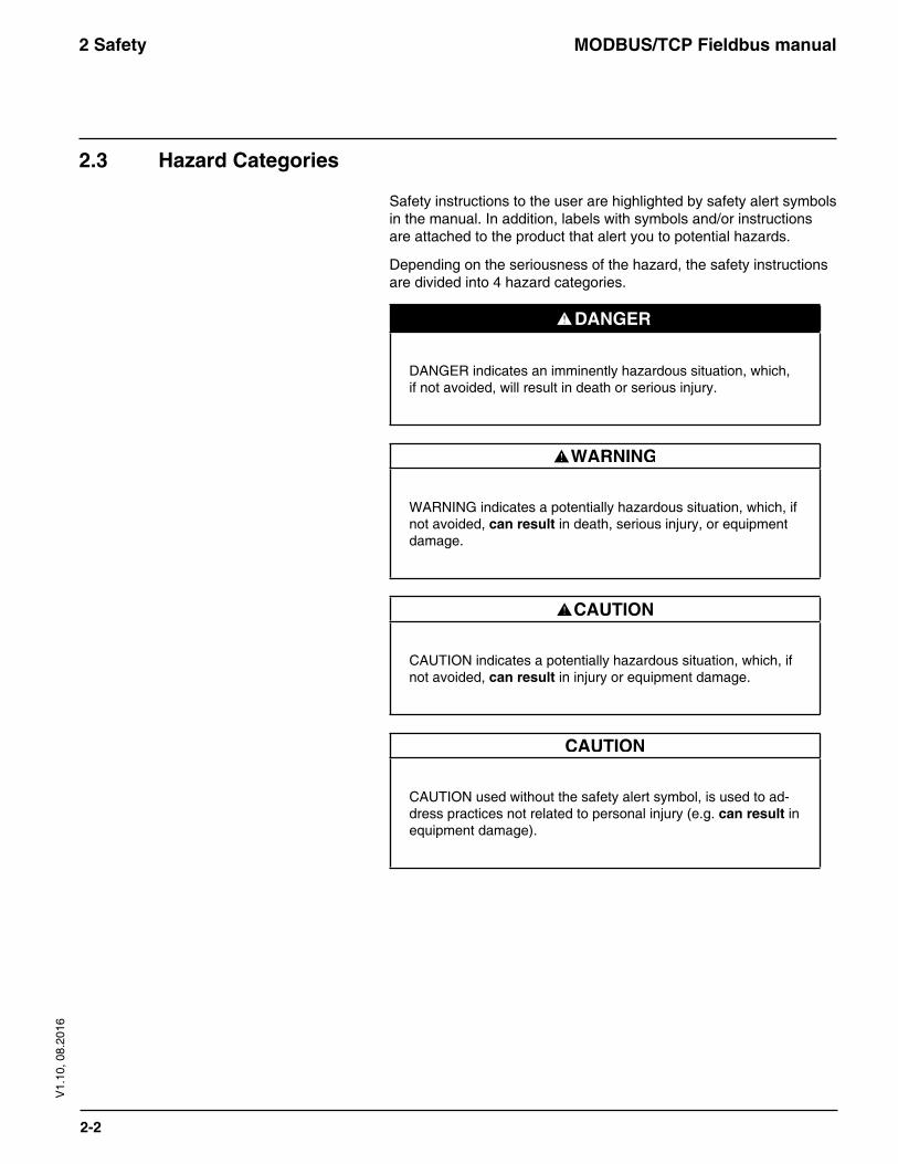
Safety instructions to the user are highlighted by safety alert symbols in the manual. In addition, labels with symbols and/or instructions are attached to the product that alert you to potential hazards.
Depending on the seriousness of the hazard, the safety instructions are divided into 4 hazard categories.
DANGER indicates an imminently hazardous situation, which, if not avoided, will result in death or serious injury.
WARNING indicates a potentially hazardous situation, which, if not avoided, canresultin death, serious injury, or equipment damage.
CAUTION indicates a potentially hazardous situation, which, if not avoided, canresult in injury or equipment damage.
CAUTION used without the safety alert symbol, is used to ad-dress practices not related to personal injury (e.g. canresult in equipment damage).
MODBUS/TCP Fieldbus manual2 Safety
2-3
V1.
10, 0
8.20
16
2.4 Basicinformation
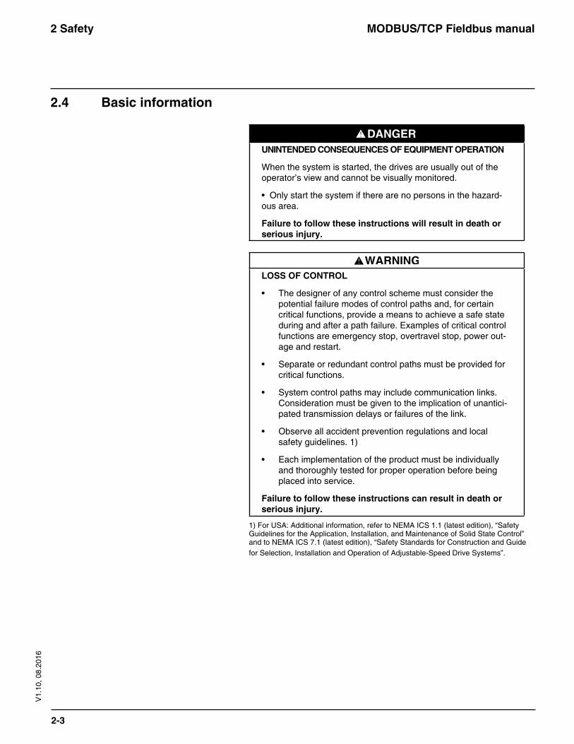
UNINTENDEDCONSEQUENCESOFEQUIPMENTOPERATION
When the system is started, the drives are usually out of the operator’s view and cannot be visually monitored.
• Only start the system if there are no persons in the hazard-ous area.
Failuretofollowtheseinstructionswillresultindeathorseriousinjury.
LOSSOFCONTROL
• The designer of any control scheme must consider the potential failure modes of control paths and, for certain critical functions, provide a means to achieve a safe state during and after a path failure. Examples of critical control functions are emergency stop, overtravel stop, power out-age and restart.
• Separate or redundant control paths must be provided for critical functions.
• System control paths may include communication links. Consideration must be given to the implication of unantici-pated transmission delays or failures of the link.
• Observe all accident prevention regulations and local safety guidelines. 1)
• Each implementation of the product must be individually and thoroughly tested for proper operation before being placed into service.
Failuretofollowtheseinstructionscanresultindeathorseriousinjury.
1) For USA: Additional information, refer to NEMA ICS 1.1 (latest edition), “Safety Guidelines for the Application, Installation, and Maintenance of Solid State Control” and to NEMA ICS 7.1 (latest edition), “Safety Standards for Construction and Guide for Selection, Installation and Operation of Adjustable-Speed Drive Systems”.
MODBUS/TCP Fieldbus manual3 MODBUS/TCP
3-1
V1.
10, 0
8.20
16
3 MODBUS Implementation
3.1 MODBUS overview
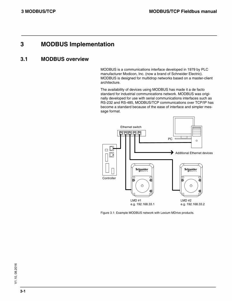
MODBUS is a communications interface developed in 1979 by PLC manufacturer Modicon, Inc. (now a brand of Schneider Electric). MODBUS is designed for multidrop networks based on a master-client architecture.
The availability of devices using MODBUS has made it a de facto standard for industrial communications network. MODBUS was origi-nally developed for use with serial communications interfaces such as RS-232 and RS-485, MODBUS/TCP communications over TCP/IP has become a standard because of the ease of interface and simpler mes-sage format.
LMD #1e.g. 192.168.33.1
LMD #2e.g. 192.168.33.2
Controller
Ethernet switch
Additional Ethernet devices
PC
Figure 3.1: Example MODBUS network with Lexium MDrive products.
MODBUS/TCP Fieldbus manual3 MODBUS/TCP
3-2
V1.
10, 0
8.20
16
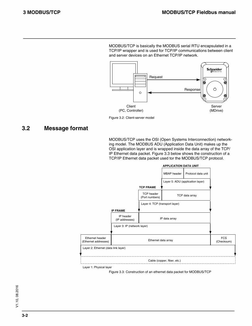
MODBUS/TCP is basically the MODBUS serial RTU encapsulated in a TCP/IP wrapper and is used for TCP/IP communications between client and server devices on an Ethernet TCP/IP network.
Client(PC, Controller)
Server(MDrive)
Request
Response
Figure 3.2: Client-server model
3.2 Message format
MODBUS/TCP uses the OSI (Open Systems Interconnection) network-ing model. The MODBUS ADU (Application Data Unit) makes up the OSI application layer and is wrapped inside the data array of the TCP/IP Ethernet data packet. Figure 3.3 below shows the construction of a TCP/IP Ethernet data packet used tor the MODBUS/TCP protocol.
Ethernet header(Ethernet addresses)
IP header(IP addresses)
TCP header(Port numbers)
MBAP header Protocol data unit
Ethernet data array
Cable (copper, fiber, etc.)
IP data array
TCP data array
FCS(Checksum)
Layer 1: Physical layer
Layer 2: Ethernet (data link layer)
Layer 3: IP (network layer)
Layer 4: TCP (transport layer)
Layer 5: ADU (application layer)
IP FRAME
TCP FRAME
APPLICATION DATA UNIT
Figure 3.3: Construction of an ethernet data packet for MODBUS/TCP
MODBUS/TCP Fieldbus manual3 MODBUS/TCP
3-3
V1.
10, 0
8.20
16
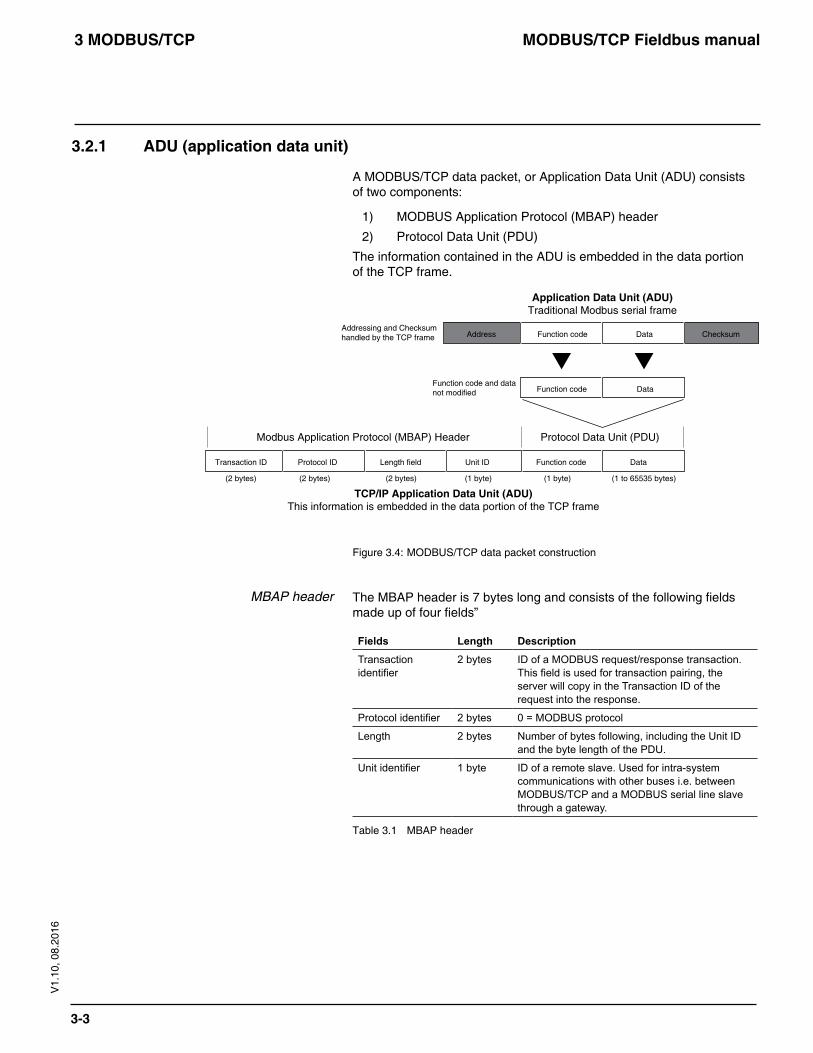
3.2.1 ADU (application data unit)
A MODBUS/TCP data packet, or Application Data Unit (ADU) consists of two components:
1) MODBUS Application Protocol (MBAP) header
2) Protocol Data Unit (PDU)
The information contained in the ADU is embedded in the data portion of the TCP frame.
Address Function code Data Checksum
Transaction ID
Addressing and Checksumhandled by the TCP frame
Function code and datanot modified
Protocol ID Length field Unit ID
Function code Data
Function code Data
Protocol Data Unit (PDU)
Application Data Unit (ADU)Traditional Modbus serial frame
TCP/IP Application Data Unit (ADU)This information is embedded in the data portion of the TCP frame
Modbus Application Protocol (MBAP) Header
(2 bytes) (2 bytes) (2 bytes) (1 byte) (1 byte) (1 to 65535 bytes)
Figure 3.4: MODBUS/TCP data packet construction
MBAP header The MBAP header is 7 bytes long and consists of the following fields made up of four fields”
Fields Length DescriptionTransaction identifier
2 bytes ID of a MODBUS request/response transaction. This field is used for transaction pairing, the server will copy in the Transaction ID of the request into the response.
Protocol identifier 2 bytes 0 = MODBUS protocol
Length 2 bytes Number of bytes following, including the Unit ID and the byte length of the PDU.
Unit identifier 1 byte ID of a remote slave. Used for intra-system communications with other buses i.e. between MODBUS/TCP and a MODBUS serial line slave through a gateway.
Table 3.1 MBAP header
MODBUS/TCP Fieldbus manual3 MODBUS/TCP
3-4
V1.
10, 0
8.20
16
Protocol Data Unit (PDU) The PDU consists of 2 parts:
1) Function code: the function code identifies the action to be taken using the data bytes that will follow. These functions are covered in detail in Section 4 of this document. Basic functions are: Reading inputs, writing coils (digital outputs), read/write registers and manufacturer specific configuration functions.
2) Data: The data contained in the PDU, it will consist of the data and/or parameters associated with the commands to operate your Lexium MDrive product.
MODBUS/TCP Fieldbus manual4 Function codes
4-1
V1.
10, 0
8.20
16
4 Function codes
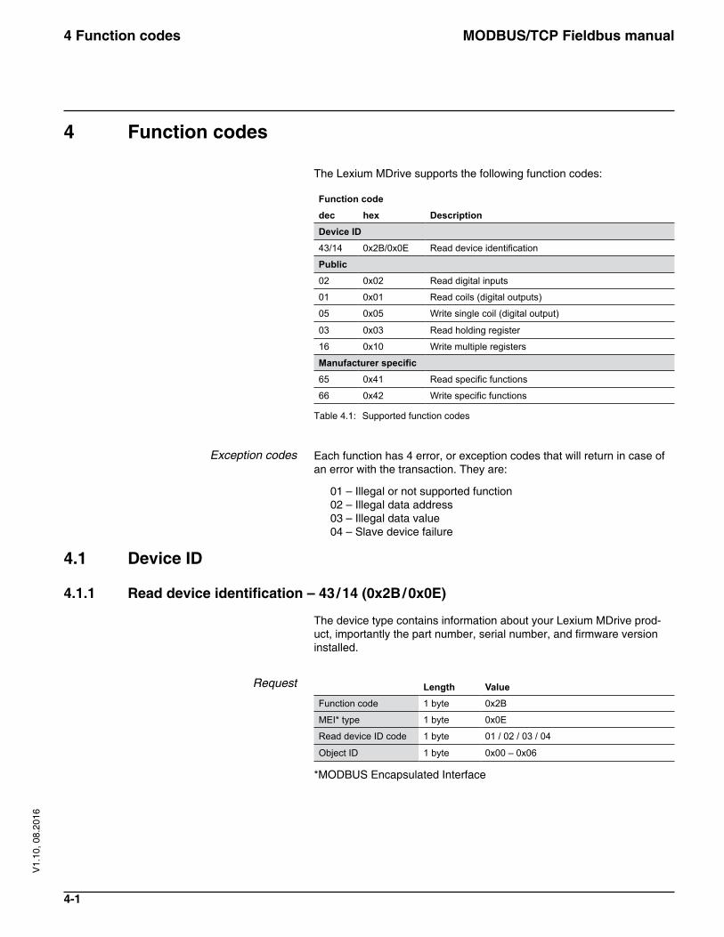
The Lexium MDrive supports the following function codes:
Function codeDescriptiondec hex
Device ID43/14 0x2B/0x0E Read device identification
Public02 0x02 Read digital inputs
01 0x01 Read coils (digital outputs)
05 0x05 Write single coil (digital output)
03 0x03 Read holding register
16 0x10 Write multiple registers
Manufacturer specific65 0x41 Read specific functions
66 0x42 Write specific functions
Table 4.1: Supported function codes
Exception codes Each function has 4 error, or exception codes that will return in case of an error with the transaction. They are:
01 – Illegal or not supported function 02 – Illegal data address 03 – Illegal data value 04 – Slave device failure
4.1 Device ID
4.1.1 Read device identification – 43 / 14 (0x2B / 0x0E)
The device type contains information about your Lexium MDrive prod-uct, importantly the part number, serial number, and firmware version installed.
Request Length ValueFunction code 1 byte 0x2B
MEI* type 1 byte 0x0E
Read device ID code 1 byte 01 / 02 / 03 / 04
Object ID 1 byte 0x00 – 0x06
*MODBUS Encapsulated Interface
MODBUS/TCP Fieldbus manual4 Function codes
4-2
V1.
10, 0
8.20
16
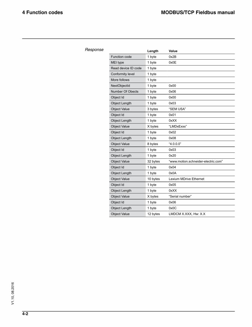
Response Length ValueFunction code 1 byte 0x2B
MEI type 1 byte 0x0E
Read device ID code 1 byte
Conformity level 1 byte
More follows 1 byte
NextObjectId 1 byte 0x00
Number Of Obects 1 byte 0x06
Object Id 1 byte 0x00
Object Length 1 byte 0x03
Object Value 3 bytes “SEM USA”
Object Id 1 byte 0x01
Object Length 1 byte 0xXX
Object Value X bytes “LMDxExxx”
Object Id 1 byte 0x02
Object Length 1 byte 0x08
Object Value 8 bytes “4.0.0.0”
Object Id 1 byte 0x03
Object Length 1 byte 0x20
Object Value 32 bytes “www.motion.schneider-electric.com”
Object Id 1 byte 0x04
Object Length 1 byte 0x0A
Object Value 10 bytes Lexium MDrive Ethernet
Object Id 1 byte 0x05
Object Length 1 byte 0xXX
Object Value X bytes “Serial number”
Object Id 1 byte 0x06
Object Length 1 byte 0x0C
Object Value 12 bytes LMDCM X.XXX, Hw: X.X
MODBUS/TCP Fieldbus manual4 Function codes
4-3
V1.
10, 0
8.20
16
4.2 Public function codes
4.2.1 Read digital inputs 02 (0x02)
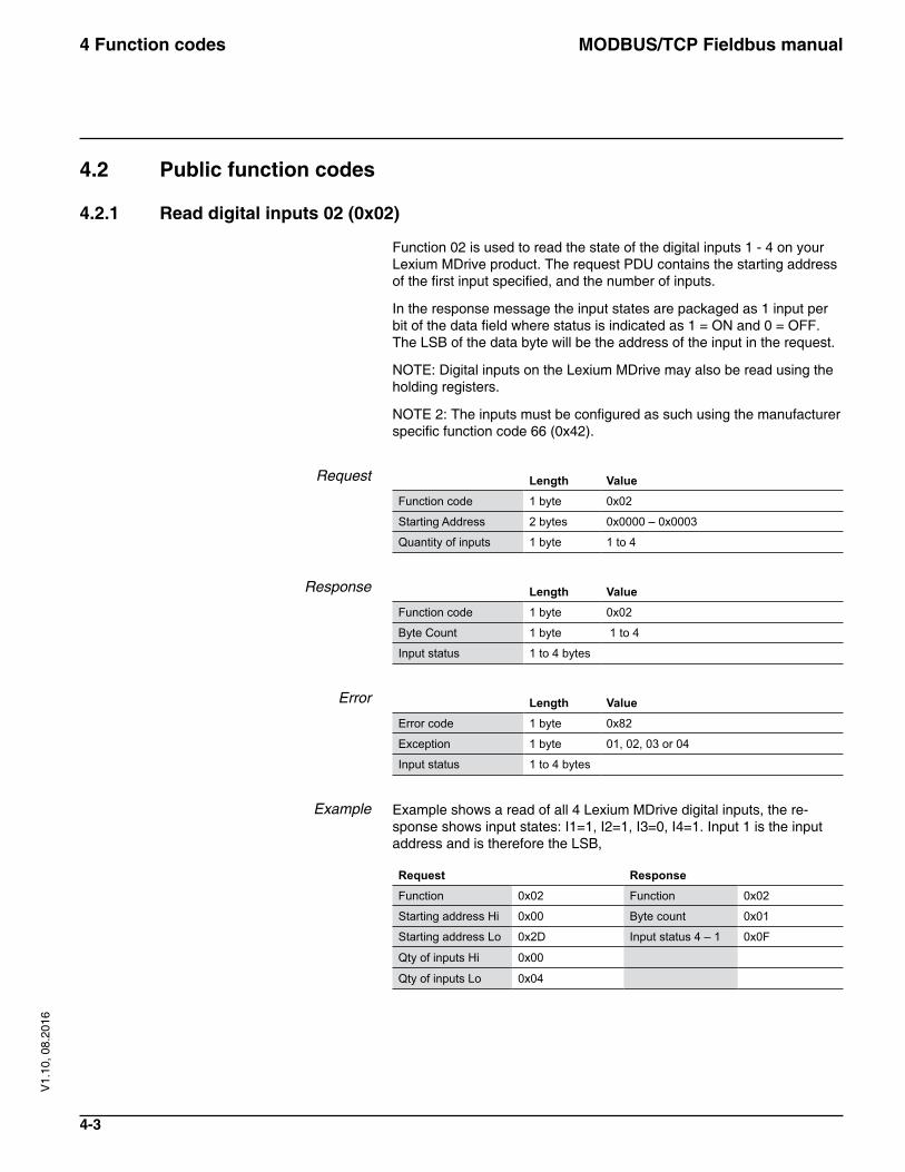
Function 02 is used to read the state of the digital inputs 1 - 4 on your Lexium MDrive product. The request PDU contains the starting address of the first input specified, and the number of inputs.
In the response message the input states are packaged as 1 input per bit of the data field where status is indicated as 1 = ON and 0 = OFF. The LSB of the data byte will be the address of the input in the request.
NOTE: Digital inputs on the Lexium MDrive may also be read using the holding registers.
NOTE 2: The inputs must be configured as such using the manufacturer specific function code 66 (0x42).
Request Length ValueFunction code 1 byte 0x02
Starting Address 2 bytes 0x0000 – 0x0003
Quantity of inputs 1 byte 1 to 4
Response Length ValueFunction code 1 byte 0x02
Byte Count 1 byte 1 to 4
Input status 1 to 4 bytes
Error Length ValueError code 1 byte 0x82
Exception 1 byte 01, 02, 03 or 04
Input status 1 to 4 bytes
Example Example shows a read of all 4 Lexium MDrive digital inputs, the re-sponse shows input states: I1=1, I2=1, I3=0, I4=1. Input 1 is the input address and is therefore the LSB,
Request ResponseFunction 0x02 Function 0x02
Starting address Hi 0x00 Byte count 0x01
Starting address Lo 0x2D Input status 4 – 1 0x0F
Qty of inputs Hi 0x00
Qty of inputs Lo 0x04
MODBUS/TCP Fieldbus manual4 Function codes
4-4
V1.
10, 0
8.20
16
4.2.2 Read coils (digital outputs) – 01 (0x01)
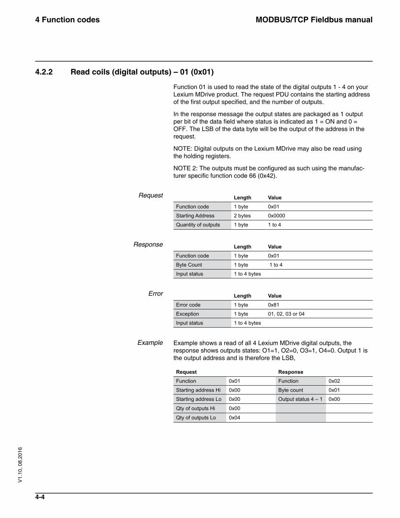
Function 01 is used to read the state of the digital outputs 1 - 4 on your Lexium MDrive product. The request PDU contains the starting address of the first output specified, and the number of outputs.
In the response message the output states are packaged as 1 output per bit of the data field where status is indicated as 1 = ON and 0 = OFF. The LSB of the data byte will be the output of the address in the request.
NOTE: Digital outputs on the Lexium MDrive may also be read using the holding registers.
NOTE 2: The outputs must be configured as such using the manufac-turer specific function code 66 (0x42).
Request Length ValueFunction code 1 byte 0x01
Starting Address 2 bytes 0x0000
Quantity of outputs 1 byte 1 to 4
Response Length ValueFunction code 1 byte 0x01
Byte Count 1 byte 1 to 4
Input status 1 to 4 bytes
Error Length ValueError code 1 byte 0x81
Exception 1 byte 01, 02, 03 or 04
Input status 1 to 4 bytes
Example Example shows a read of all 4 Lexium MDrive digital outputs, the response shows outputs states: O1=1, O2=0, O3=1, O4=0. Output 1 is the output address and is therefore the LSB,
Request ResponseFunction 0x01 Function 0x02
Starting address Hi 0x00 Byte count 0x01
Starting address Lo 0x00 Output status 4 – 1 0x00
Qty of outputs Hi 0x00
Qty of outputs Lo 0x04
MODBUS/TCP Fieldbus manual4 Function codes
4-5
V1.
10, 0
8.20
16
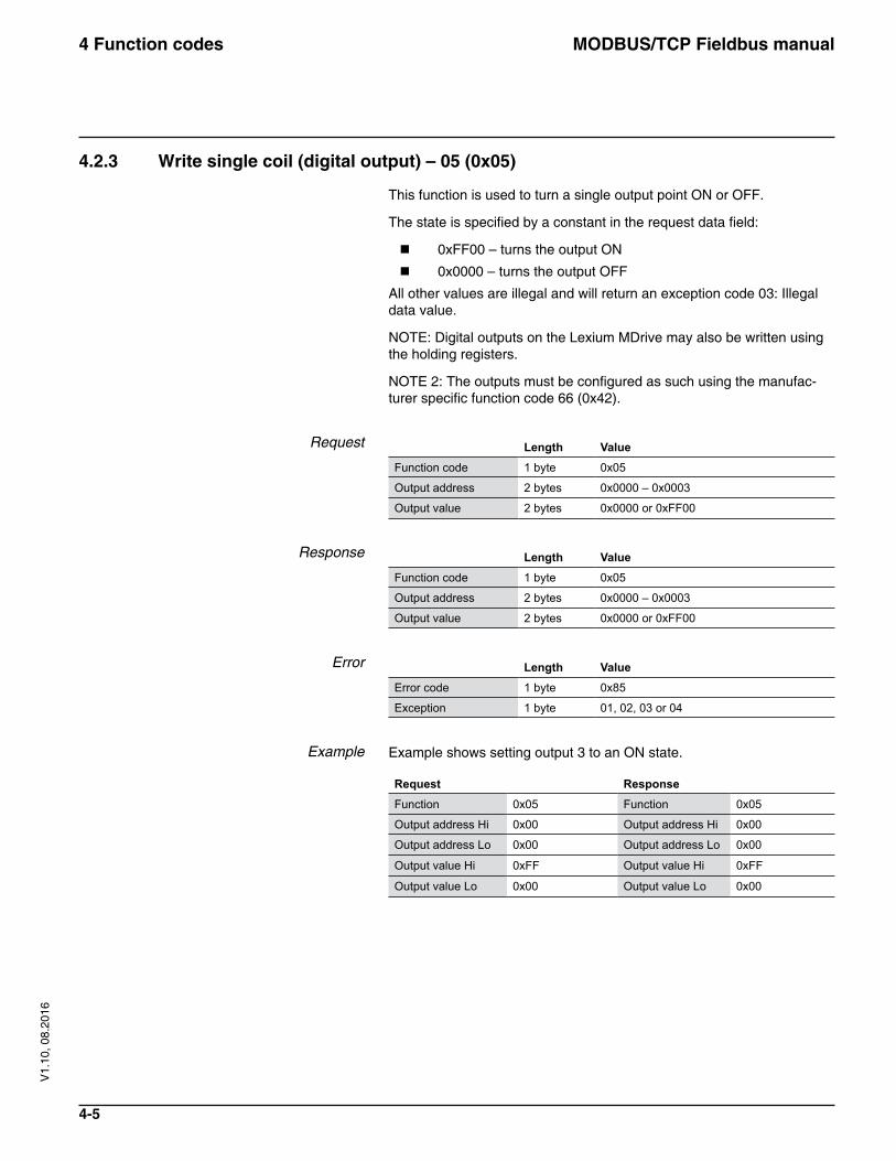
4.2.3 Write single coil (digital output) – 05 (0x05)
This function is used to turn a single output point ON or OFF.
The state is specified by a constant in the request data field:
� 0xFF00 – turns the output ON
� 0x0000 – turns the output OFF
All other values are illegal and will return an exception code 03: Illegal data value.
NOTE: Digital outputs on the Lexium MDrive may also be written using the holding registers.
NOTE 2: The outputs must be configured as such using the manufac-turer specific function code 66 (0x42).
Request Length ValueFunction code 1 byte 0x05
Output address 2 bytes 0x0000 – 0x0003
Output value 2 bytes 0x0000 or 0xFF00
Response Length ValueFunction code 1 byte 0x05
Output address 2 bytes 0x0000 – 0x0003
Output value 2 bytes 0x0000 or 0xFF00
Error Length ValueError code 1 byte 0x85
Exception 1 byte 01, 02, 03 or 04
Example Example shows setting output 3 to an ON state.
Request ResponseFunction 0x05 Function 0x05
Output address Hi 0x00 Output address Hi 0x00
Output address Lo 0x00 Output address Lo 0x00
Output value Hi 0xFF Output value Hi 0xFF
Output value Lo 0x00 Output value Lo 0x00
MODBUS/TCP Fieldbus manual4 Function codes
4-6
V1.
10, 0
8.20
16
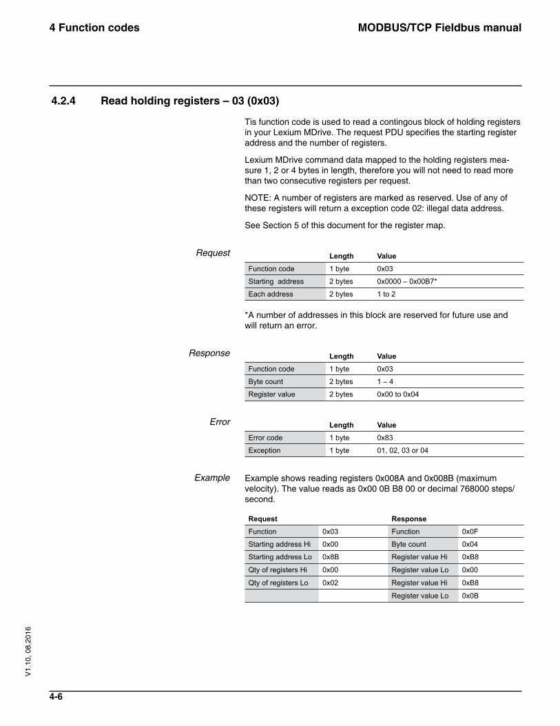
4.2.4 Read holding registers – 03 (0x03)
Tis function code is used to read a contingous block of holding registers in your Lexium MDrive. The request PDU specifies the starting register address and the number of registers.
Lexium MDrive command data mapped to the holding registers mea-sure 1, 2 or 4 bytes in length, therefore you will not need to read more than two consecutive registers per request.
NOTE: A number of registers are marked as reserved. Use of any of these registers will return a exception code 02: illegal data address.
See Section 5 of this document for the register map.
Request Length ValueFunction code 1 byte 0x03
Starting address 2 bytes 0x0000 – 0x00B7*
Each address 2 bytes 1 to 2 *A number of addresses in this block are reserved for future use and will return an error.
Response Length ValueFunction code 1 byte 0x03
Byte count 2 bytes 1 – 4
Register value 2 bytes 0x00 to 0x04
Error Length ValueError code 1 byte 0x83
Exception 1 byte 01, 02, 03 or 04
Example Example shows reading registers 0x008A and 0x008B (maximum velocity). The value reads as 0x00 0B B8 00 or decimal 768000 steps/second.
Request ResponseFunction 0x03 Function 0x0F
Starting address Hi 0x00 Byte count 0x04
Starting address Lo 0x8B Register value Hi 0xB8
Qty of registers Hi 0x00 Register value Lo 0x00
Qty of registers Lo 0x02 Register value Hi 0xB8
Register value Lo 0x0B
MODBUS/TCP Fieldbus manual4 Function codes
4-7
V1.
10, 0
8.20
16
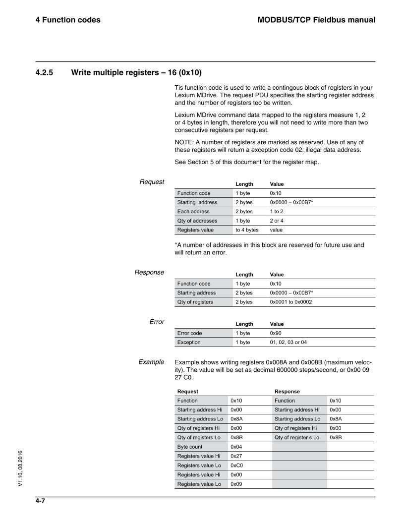
4.2.5 Write multiple registers – 16 (0x10)
Tis function code is used to write a contingous block of registers in your Lexium MDrive. The request PDU specifies the starting register address and the number of registers teo be written.
Lexium MDrive command data mapped to the registers measure 1, 2 or 4 bytes in length, therefore you will not need to write more than two consecutive registers per request.
NOTE: A number of registers are marked as reserved. Use of any of these registers will return a exception code 02: illegal data address.
See Section 5 of this document for the register map.
Request Length ValueFunction code 1 byte 0x10
Starting address 2 bytes 0x0000 – 0x00B7*
Each address 2 bytes 1 to 2
Qty of addresses 1 byte 2 or 4
Registers value to 4 bytes value *A number of addresses in this block are reserved for future use and will return an error.
Response Length ValueFunction code 1 byte 0x10
Starting address 2 bytes 0x0000 – 0x00B7*
Qty of registers 2 bytes 0x0001 to 0x0002
Error Length ValueError code 1 byte 0x90
Exception 1 byte 01, 02, 03 or 04
Example Example shows writing registers 0x008A and 0x008B (maximum veloc-ity). The value will be set as decimal 600000 steps/second, or 0x00 09 27 C0.
Request ResponseFunction 0x10 Function 0x10
Starting address Hi 0x00 Starting address Hi 0x00
Starting address Lo 0x8A Starting address Lo 0x8A
Qty of registers Hi 0x00 Qty of registers Hi 0x00
Qty of registers Lo 0x8B Qty of register s Lo 0x8B
Byte count 0x04
Registers value Hi 0x27
Registers value Lo 0xC0
Registers value Hi 0x00
Registers value Lo 0x09
MODBUS/TCP Fieldbus manual4 Function codes
4-8
V1.
10, 0
8.20
16
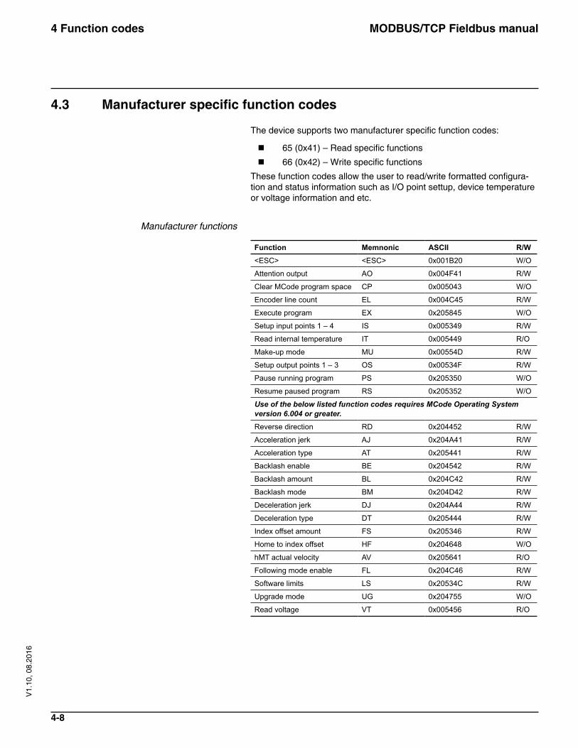
4.3 Manufacturer specific function codes
The device supports two manufacturer specific function codes:
� 65 (0x41) – Read specific functions
� 66 (0x42) – Write specific functions
These function codes allow the user to read/write formatted configura-tion and status information such as I/O point settup, device temperature or voltage information and etc.
Manufacturer functions
Function Memnonic ASCII R/W<ESC> <ESC> 0x001B20 W/O
Attention output AO 0x004F41 R/W
Clear MCode program space CP 0x005043 W/O
Encoder line count EL 0x004C45 R/W
Execute program EX 0x205845 W/O
Setup input points 1 – 4 IS 0x005349 R/W
Read internal temperature IT 0x005449 R/O
Make-up mode MU 0x00554D R/W
Setup output points 1 – 3 OS 0x00534F R/W
Pause running program PS 0x205350 W/O
Resume paused program RS 0x205352 W/O
Use of the below listed function codes requires MCode Operating System version 6.004 or greater.Reverse direction RD 0x204452 R/W
Acceleration jerk AJ 0x204A41 R/W
Acceleration type AT 0x205441 R/W
Backlash enable BE 0x204542 R/W
Backlash amount BL 0x204C42 R/W
Backlash mode BM 0x204D42 R/W
Deceleration jerk DJ 0x204A44 R/W
Deceleration type DT 0x205444 R/W
Index offset amount FS 0x205346 R/W
Home to index offset HF 0x204648 W/O
hMT actual velocity AV 0x205641 R/O
Following mode enable FL 0x204C46 R/W
Software limits LS 0x20534C R/W
Upgrade mode UG 0x204755 W/O
Read voltage VT 0x005456 R/O
MODBUS/TCP Fieldbus manual4 Function codes
4-9
V1.
10, 0
8.20
16
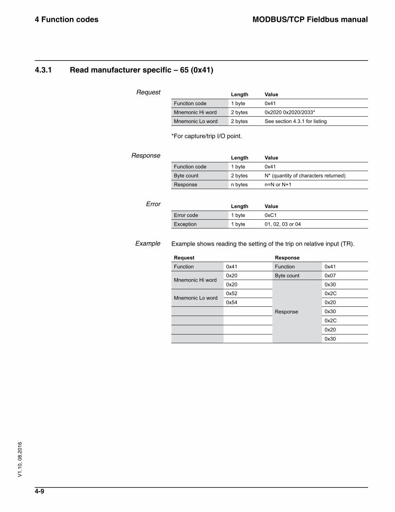
4.3.1 Read manufacturer specific – 65 (0x41)
Request Length ValueFunction code 1 byte 0x41
Mnemonic Hi word 2 bytes 0x2020 0x2020/2033*
Mnemonic Lo word 2 bytes See section 4.3.1 for listing *For capture/trip I/O point.
Response Length ValueFunction code 1 byte 0x41
Byte count 2 bytes N* (quantity of characters returned)
Response n bytes n=N or N+1
Error Length ValueError code 1 byte 0xC1
Exception 1 byte 01, 02, 03 or 04
Example Example shows reading the setting of the trip on relative input (TR).
Request ResponseFunction 0x41 Function 0x41
Mnemonic Hi word0x20 Byte count 0x07
0x20
Response
0x30
Mnemonic Lo word0x52 0x2C
0x54 0x20
0x30
0x2C
0x20
0x30
MODBUS/TCP Fieldbus manual4 Function codes
4-10
V1.
10, 0
8.20
16
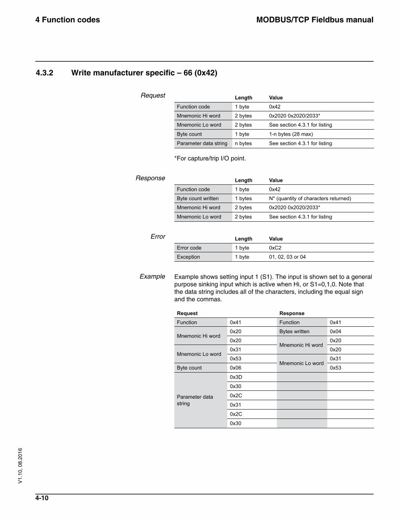
4.3.2 Write manufacturer specific – 66 (0x42)
Request Length ValueFunction code 1 byte 0x42
Mnemonic Hi word 2 bytes 0x2020 0x2020/2033*
Mnemonic Lo word 2 bytes See section 4.3.1 for listing
Byte count 1 byte 1-n bytes (28 max)
Parameter data string n bytes See section 4.3.1 for listing *For capture/trip I/O point.
Response Length ValueFunction code 1 byte 0x42
Byte count written 1 bytes N* (quantity of characters returned)
Mnemonic Hi word 2 bytes 0x2020 0x2020/2033*
Mnemonic Lo word 2 bytes See section 4.3.1 for listing
Error Length ValueError code 1 byte 0xC2
Exception 1 byte 01, 02, 03 or 04
Example Example shows setting input 1 (S1). The input is shown set to a general purpose sinking input which is active when Hi, or S1=0,1,0. Note that the data string includes all of the characters, including the equal sign and the commas.
Request ResponseFunction 0x41 Function 0x41
Mnemonic Hi word0x20 Bytes written 0x04
0x20Mnemonic Hi word
0x20
Mnemonic Lo word0x31 0x20
0x53Mnemonic Lo word
0x31
Byte count 0x06 0x53
Parameter data string
0x3D
0x30
0x2C
0x31
0x2C
0x30
MODBUS/TCP Fieldbus manual4 Function codes
4-11
V1.
10, 0
8.20
16
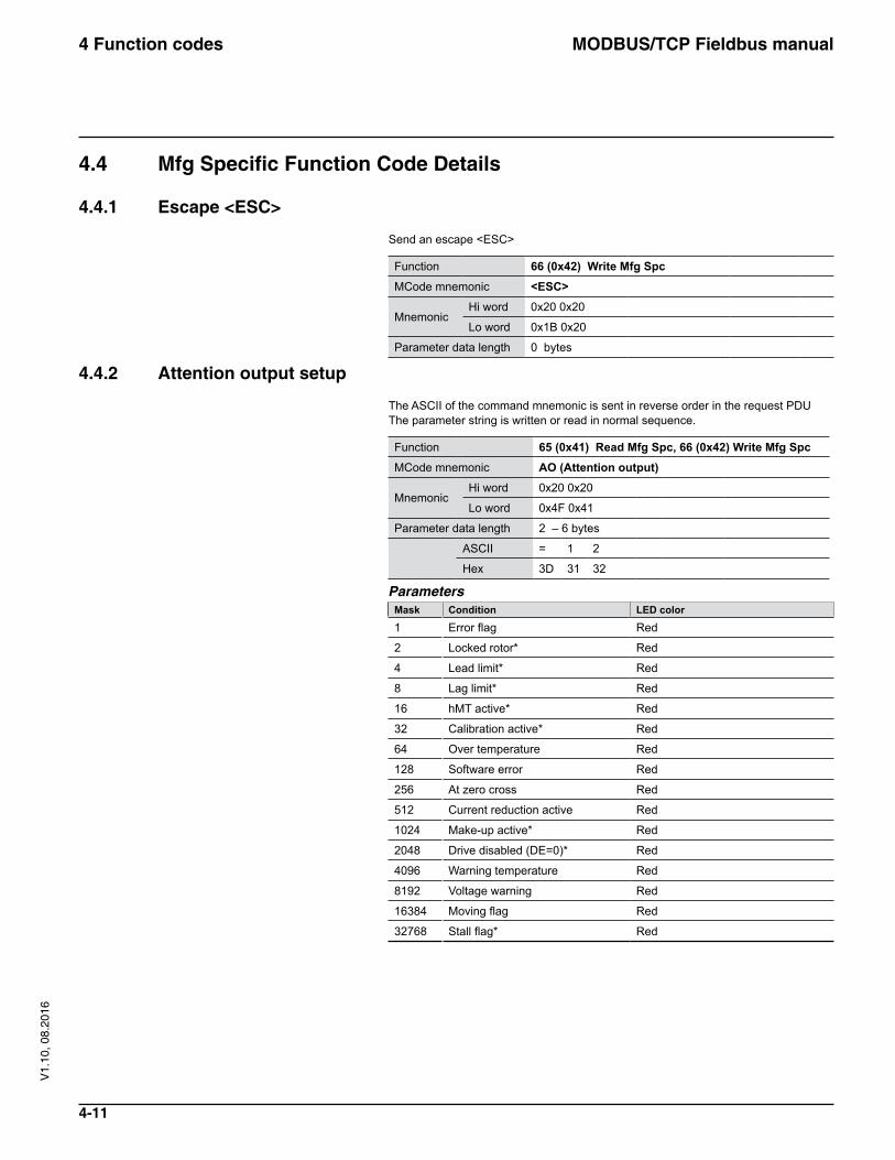
4.4 Mfg Specific Function Code Details
4.4.1 Escape <ESC>
Send an escape <ESC>
Function 66 (0x42) Write Mfg SpcMCode mnemonic <ESC>
MnemonicHi word 0x20 0x20
Lo word 0x1B 0x20
Parameter data length 0 bytes
4.4.2 Attention output setup
The ASCII of the command mnemonic is sent in reverse order in the request PDU The parameter string is written or read in normal sequence.
Function 65 (0x41) Read Mfg Spc, 66 (0x42) Write Mfg SpcMCode mnemonic AO (Attention output)
MnemonicHi word 0x20 0x20
Lo word 0x4F 0x41
Parameter data length 2 – 6 bytes
ASCII = 1 2
Hex 3D 31 32
ParametersMask Condition LED color
1 Error flag Red
2 Locked rotor* Red
4 Lead limit* Red
8 Lag limit* Red
16 hMT active* Red
32 Calibration active* Red
64 Over temperature Red
128 Software error Red
256 At zero cross Red
512 Current reduction active Red
1024 Make-up active* Red
2048 Drive disabled (DE=0)* Red
4096 Warning temperature Red
8192 Voltage warning Red
16384 Moving flag Red
32768 Stall flag* Red
MODBUS/TCP Fieldbus manual4 Function codes
4-12
V1.
10, 0
8.20
16
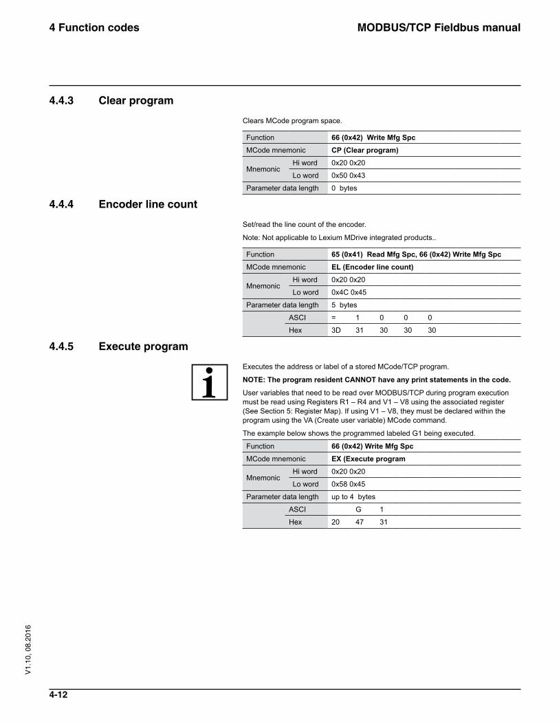
4.4.3 Clear program
Clears MCode program space.
Function 66 (0x42) Write Mfg SpcMCode mnemonic CP (Clear program)
MnemonicHi word 0x20 0x20
Lo word 0x50 0x43
Parameter data length 0 bytes
4.4.4 Encoder line count
Set/read the line count of the encoder.
Note: Not applicable to Lexium MDrive integrated products..
Function 65 (0x41) Read Mfg Spc, 66 (0x42) Write Mfg SpcMCode mnemonic EL (Encoder line count)
MnemonicHi word 0x20 0x20
Lo word 0x4C 0x45
Parameter data length 5 bytes
ASCI = 1 0 0 0
Hex 3D 31 30 30 30
4.4.5 Execute program
Executes the address or label of a stored MCode/TCP program.
NOTE: The program resident CANNOT have any print statements in the code.
User variables that need to be read over MODBUS/TCP during program execution must be read using Registers R1 – R4 and V1 – V8 using the associated register (See Section 5: Register Map). If using V1 – V8, they must be declared within the program using the VA (Create user variable) MCode command.
The example below shows the programmed labeled G1 being executed.
Function 66 (0x42) Write Mfg SpcMCode mnemonic EX (Execute program
MnemonicHi word 0x20 0x20
Lo word 0x58 0x45
Parameter data length up to 4 bytes
ASCI G 1
Hex 20 47 31
MODBUS/TCP Fieldbus manual4 Function codes
4-13
V1.
10, 0
8.20
16
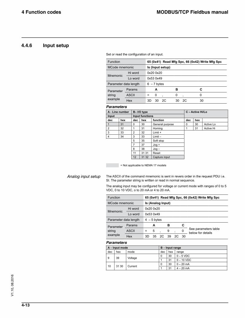
4.4.6 Input setup
Set or read the configuration of an input.
Function 65 (0x41) Read Mfg Spc, 66 (0x42) Write Mfg SpcMCode mnemonic Is (Input setup)
MnemonicHi word 0x20 0x20
Lo word 0x53 0x49
Parameter data length 6 – 7 bytes
Parameter string example
Params A B CASCII = 0 , 0 , 0
Hex 3D 30 2C 30 2C 30
ParametersA - Line number B– I/O type C – Active Hi/LoInput Input functionsdec hex dec hex function dec hex1 31 0 30 General purpose 0 30 Active Lo2 32 1 31 Homing 1 31 Active Hi3 33 2 32 Limit +4 34 3 33 Limit –
5 35 Soft stop7 37 Jog +8 38 Jog –11 31 31 Reset12 31 32 Capture input
= Not applicable to NEMA 17 models
Analog input setup The ASCII of the command mnemonic is sent in revers order in the request PDU i.e. SI. The parameter string is written or read in normal sequence.
The analog input may be configured for voltage or current mode with ranges of 0 to 5 VDC, 0 to 10 VDC, o to 20 mA or 4 to 20 mA.
Function 65 (0x41) Read Mfg Spc, 66 (0x42) Write Mfg SpcMCode mnemonic Is (Analog Input)
MnemonicHi word 0x20 0x20
Lo word 0x53 0x49
Parameter data length 4 – 5 bytes
Parameter string example
Params A B CSee parameters table below for detailsASCII = 5 , 9 , 0
Hex 3D 35 2C 39 2C 30
ParametersA – Input mode B – Input rangedec hex mode dec hex range
9 39 Voltage0 30 0 – 5 VDC1 31 0 – 10 VDC
10 31 30 Current0 30 0 – 20 mA1 31 4 – 20 mA
MODBUS/TCP Fieldbus manual4 Function codes
4-14
V1.
10, 0
8.20
16
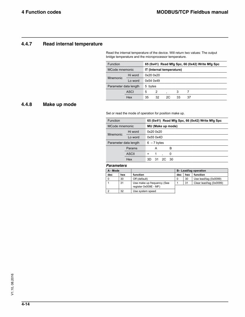
4.4.7 Read internal temperature
Read the internal temperature of the device. Will return two values: The output bridge temperature and the microprocessor temperature.
Function 65 (0x41) Read Mfg Spc, 66 (0x42) Write Mfg SpcMCode mnemonic IT (Internal temperature)
MnemonicHi word 0x20 0x20
Lo word 0x54 0x49
Parameter data length 5 bytes
ASCI 5 2 , 3 7
Hex 35 32 2C 33 37
4.4.8 Make up mode
Set or read the mode of operation for position make up.
Function 65 (0x41) Read Mfg Spc, 66 (0x42) Write Mfg SpcMCode mnemonic MU (Make up mode)
MnemonicHi word 0x20 0x20
Lo word 0x55 0x4D
Parameter data length 6 – 7 bytes
Params A B
ASCII = 1 , 0
Hex 3D 31 2C 30
ParametersA - Mode B– Lead/lag operationdec hex function dec hex function0 30 Off (default) 0 30 Use lead/lag (0x0099)1 31 Use make up frequency (See
register 0x009E - MF)1 31 Clear lead/lag (0x0099)
2 32 Use system speed
MODBUS/TCP Fieldbus manual4 Function codes
4-15
V1.
10, 0
8.20
16
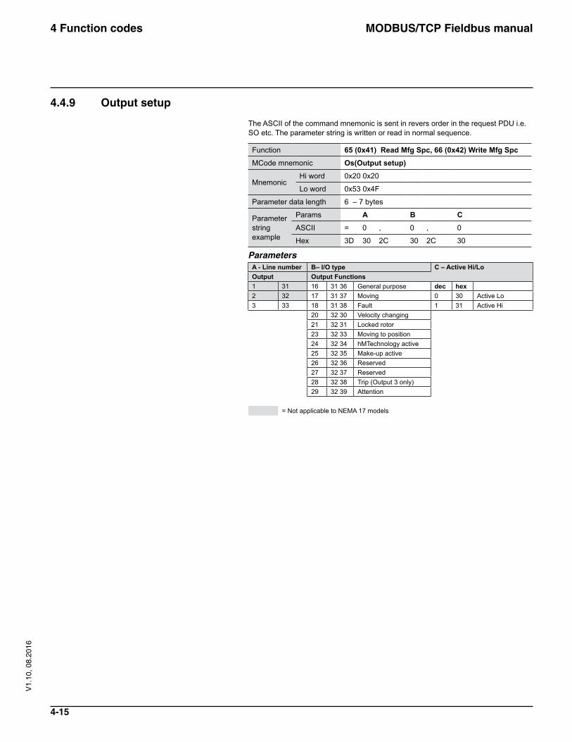
4.4.9 Output setup
The ASCII of the command mnemonic is sent in revers order in the request PDU i.e. SO etc. The parameter string is written or read in normal sequence.
Function 65 (0x41) Read Mfg Spc, 66 (0x42) Write Mfg SpcMCode mnemonic Os(Output setup)
MnemonicHi word 0x20 0x20
Lo word 0x53 0x4F
Parameter data length 6 – 7 bytes
Parameter string example
Params A B CASCII = 0 , 0 , 0
Hex 3D 30 2C 30 2C 30
ParametersA - Line number B– I/O type C – Active Hi/LoOutput Output Functions1 31 16 31 36 General purpose dec hex2 32 17 31 37 Moving 0 30 Active Lo3 33 18 31 38 Fault 1 31 Active Hi
20 32 30 Velocity changing21 32 31 Locked rotor23 32 33 Moving to position24 32 34 hMTechnology active25 32 35 Make-up active26 32 36 Reserved27 32 37 Reserved28 32 38 Trip (Output 3 only)29 32 39 Attention
= Not applicable to NEMA 17 models
MODBUS/TCP Fieldbus manual4 Function codes
4-16
V1.
10, 0
8.20
16
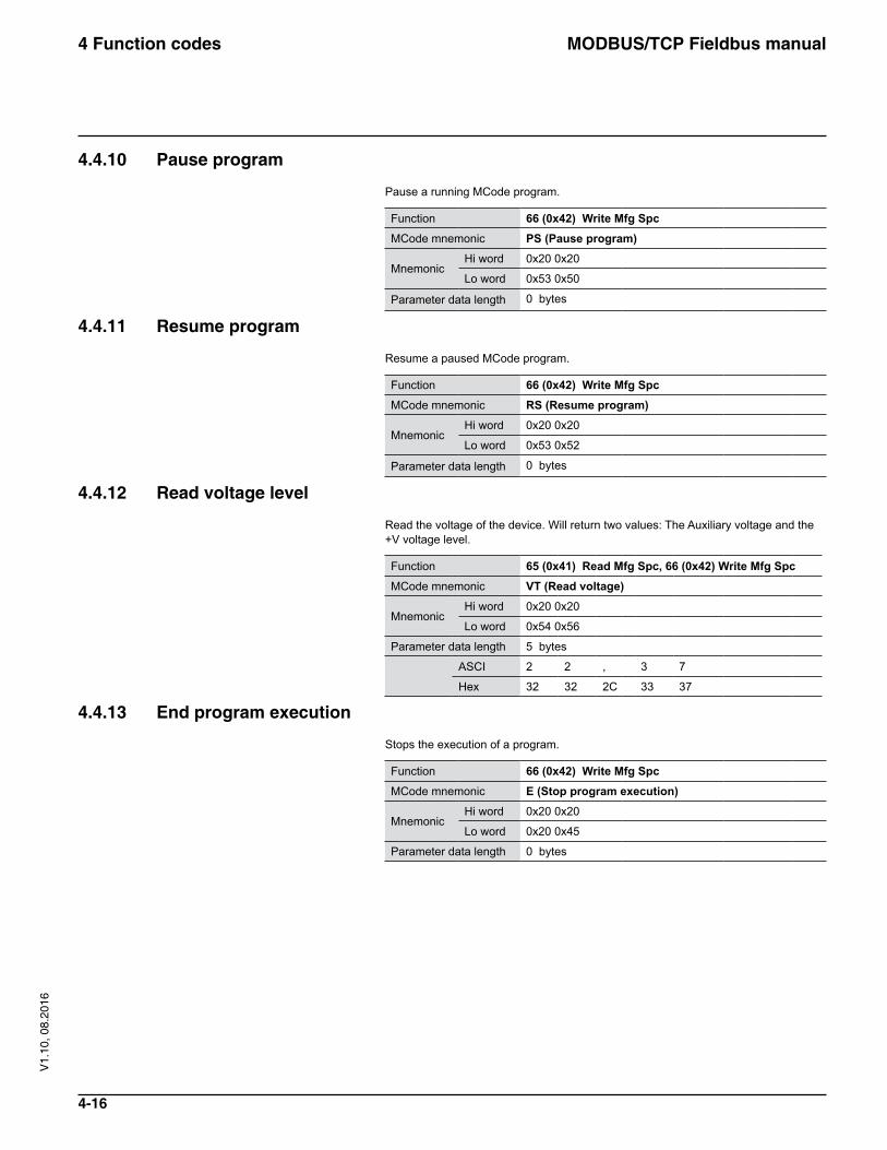
4.4.10 Pause program
Pause a running MCode program.
Function 66 (0x42) Write Mfg SpcMCode mnemonic PS (Pause program)
MnemonicHi word 0x20 0x20
Lo word 0x53 0x50
Parameter data length 0 bytes
4.4.11 Resume program
Resume a paused MCode program.
Function 66 (0x42) Write Mfg SpcMCode mnemonic RS (Resume program)
MnemonicHi word 0x20 0x20
Lo word 0x53 0x52
Parameter data length 0 bytes
4.4.12 Read voltage level
Read the voltage of the device. Will return two values: The Auxiliary voltage and the +V voltage level.
Function 65 (0x41) Read Mfg Spc, 66 (0x42) Write Mfg SpcMCode mnemonic VT (Read voltage)
MnemonicHi word 0x20 0x20
Lo word 0x54 0x56
Parameter data length 5 bytes
ASCI 2 2 , 3 7
Hex 32 32 2C 33 37
4.4.13 End program execution
Stops the execution of a program.
Function 66 (0x42) Write Mfg SpcMCode mnemonic E (Stop program execution)
MnemonicHi word 0x20 0x20
Lo word 0x20 0x45
Parameter data length 0 bytes
MODBUS/TCP Fieldbus manual4 Function codes
4-17
V1.
10, 0
8.20
16
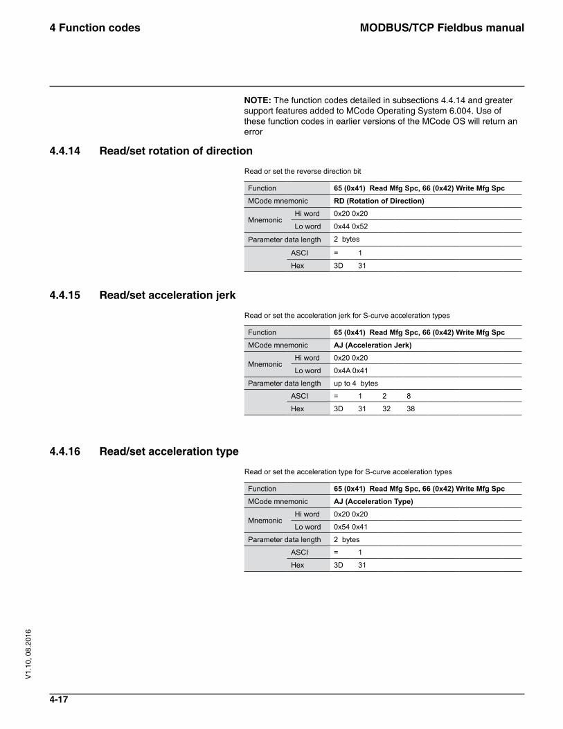
NOTE: The function codes detailed in subsections 4.4.14 and greater support features added to MCode Operating System 6.004. Use of these function codes in earlier versions of the MCode OS will return an error
4.4.14 Read/set rotation of direction
Read or set the reverse direction bit
Function 65 (0x41) Read Mfg Spc, 66 (0x42) Write Mfg SpcMCode mnemonic RD (Rotation of Direction)
MnemonicHi word 0x20 0x20
Lo word 0x44 0x52
Parameter data length 2 bytes
ASCI = 1
Hex 3D 31
4.4.15 Read/set acceleration jerk
Read or set the acceleration jerk for S-curve acceleration types
Function 65 (0x41) Read Mfg Spc, 66 (0x42) Write Mfg SpcMCode mnemonic AJ (Acceleration Jerk)
MnemonicHi word 0x20 0x20
Lo word 0x4A 0x41
Parameter data length up to 4 bytes
ASCI = 1 2 8
Hex 3D 31 32 38
4.4.16 Read/set acceleration type
Read or set the acceleration type for S-curve acceleration types
Function 65 (0x41) Read Mfg Spc, 66 (0x42) Write Mfg SpcMCode mnemonic AJ (Acceleration Type)
MnemonicHi word 0x20 0x20
Lo word 0x54 0x41
Parameter data length 2 bytes
ASCI = 1
Hex 3D 31
MODBUS/TCP Fieldbus manual4 Function codes
4-18
V1.
10, 0
8.20
16
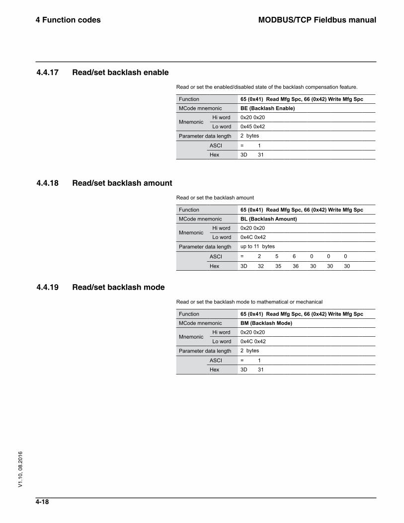
4.4.17 Read/set backlash enable
Read or set the enabled/disabled state of the backlash compensation feature.
Function 65 (0x41) Read Mfg Spc, 66 (0x42) Write Mfg SpcMCode mnemonic BE (Backlash Enable)
MnemonicHi word 0x20 0x20
Lo word 0x45 0x42
Parameter data length 2 bytes
ASCI = 1
Hex 3D 31
4.4.18 Read/set backlash amount
Read or set the backlash amount
Function 65 (0x41) Read Mfg Spc, 66 (0x42) Write Mfg SpcMCode mnemonic BL (Backlash Amount)
MnemonicHi word 0x20 0x20
Lo word 0x4C 0x42
Parameter data length up to 11 bytes
ASCI = 2 5 6 0 0 0
Hex 3D 32 35 36 30 30 30
4.4.19 Read/set backlash mode
Read or set the backlash mode to mathematical or mechanical
Function 65 (0x41) Read Mfg Spc, 66 (0x42) Write Mfg SpcMCode mnemonic BM (Backlash Mode)
MnemonicHi word 0x20 0x20
Lo word 0x4C 0x42
Parameter data length 2 bytes
ASCI = 1
Hex 3D 31
MODBUS/TCP Fieldbus manual4 Function codes
4-19
V1.
10, 0
8.20
16
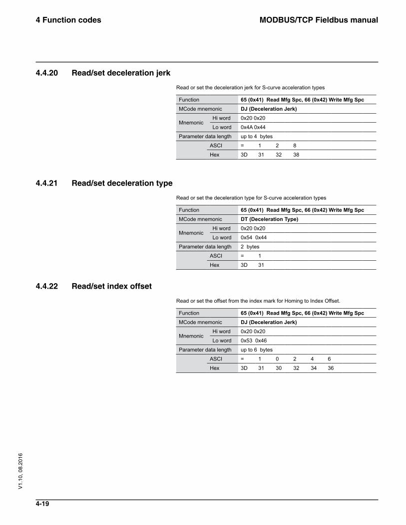
4.4.20 Read/set deceleration jerk
Read or set the deceleration jerk for S-curve acceleration types
Function 65 (0x41) Read Mfg Spc, 66 (0x42) Write Mfg SpcMCode mnemonic DJ (Deceleration Jerk)
MnemonicHi word 0x20 0x20
Lo word 0x4A 0x44
Parameter data length up to 4 bytes
ASCI = 1 2 8
Hex 3D 31 32 38
4.4.21 Read/set deceleration type
Read or set the deceleration type for S-curve acceleration types
Function 65 (0x41) Read Mfg Spc, 66 (0x42) Write Mfg SpcMCode mnemonic DT (Deceleration Type)
MnemonicHi word 0x20 0x20
Lo word 0x54 0x44
Parameter data length 2 bytes
ASCI = 1
Hex 3D 31
4.4.22 Read/set index offset
Read or set the offset from the index mark for Homing to Index Offset.
Function 65 (0x41) Read Mfg Spc, 66 (0x42) Write Mfg SpcMCode mnemonic DJ (Deceleration Jerk)
MnemonicHi word 0x20 0x20
Lo word 0x53 0x46
Parameter data length up to 6 bytes
ASCI = 1 0 2 4 6
Hex 3D 31 30 32 34 36
MODBUS/TCP Fieldbus manual4 Function codes
4-20
V1.
10, 0
8.20
16
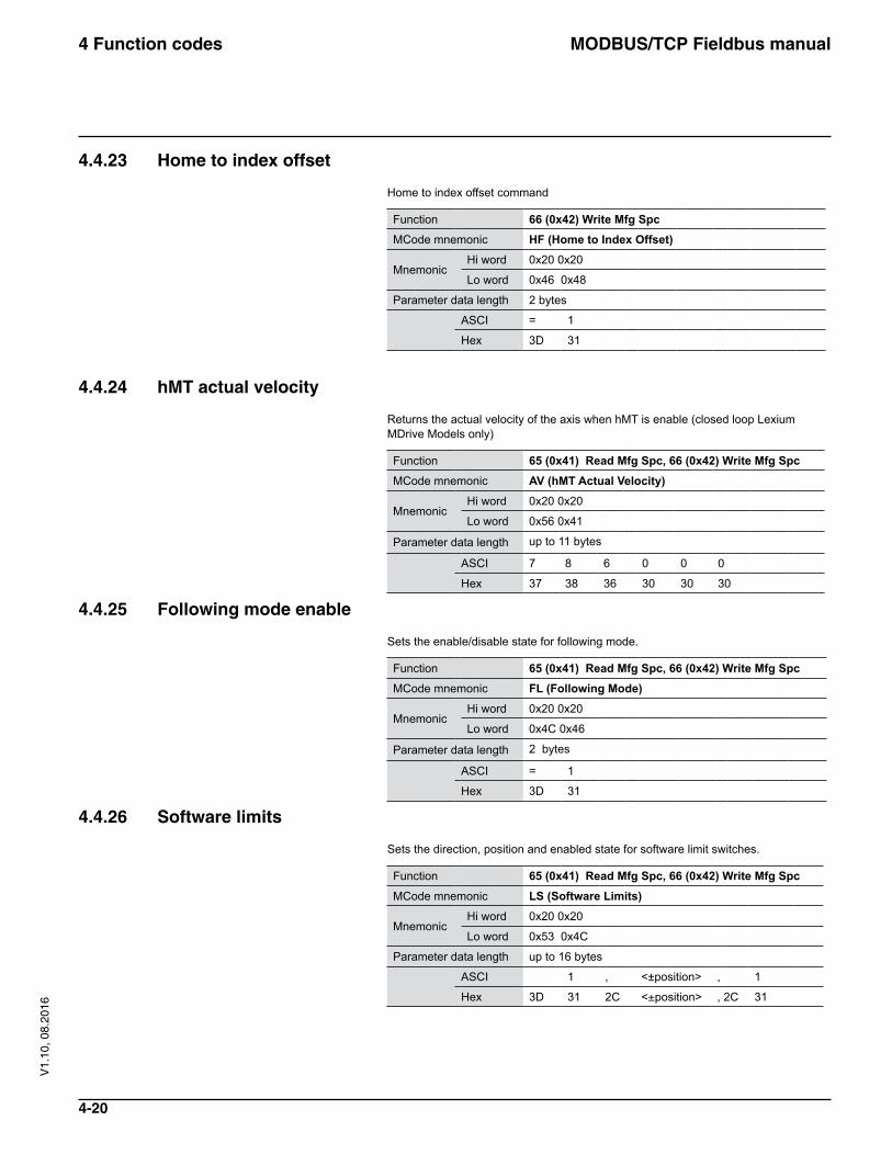
4.4.23 Home to index offset
Home to index offset command
Function 66 (0x42) Write Mfg SpcMCode mnemonic HF (Home to Index Offset)
MnemonicHi word 0x20 0x20
Lo word 0x46 0x48
Parameter data length 2 bytes
ASCI = 1
Hex 3D 31
4.4.24 hMT actual velocity
Returns the actual velocity of the axis when hMT is enable (closed loop Lexium MDrive Models only)
Function 65 (0x41) Read Mfg Spc, 66 (0x42) Write Mfg SpcMCode mnemonic AV (hMT Actual Velocity)
MnemonicHi word 0x20 0x20
Lo word 0x56 0x41
Parameter data length up to 11 bytes
ASCI 7 8 6 0 0 0
Hex 37 38 36 30 30 30
4.4.25 Following mode enable
Sets the enable/disable state for following mode.
Function 65 (0x41) Read Mfg Spc, 66 (0x42) Write Mfg SpcMCode mnemonic FL (Following Mode)
MnemonicHi word 0x20 0x20
Lo word 0x4C 0x46
Parameter data length 2 bytes
ASCI = 1
Hex 3D 31
4.4.26 Software limits
Sets the direction, position and enabled state for software limit switches.
Function 65 (0x41) Read Mfg Spc, 66 (0x42) Write Mfg SpcMCode mnemonic LS (Software Limits)
MnemonicHi word 0x20 0x20
Lo word 0x53 0x4C
Parameter data length up to 16 bytes
ASCI 1 , <±position> , 1
Hex 3D 31 2C <±position> , 2C 31
MODBUS/TCP Fieldbus manual4 Function codes
4-21
V1.
10, 0
8.20
16
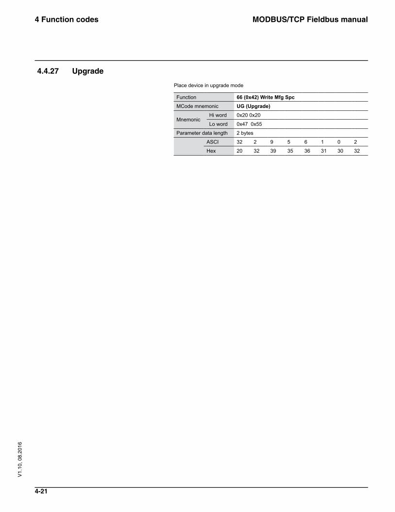
4.4.27 Upgrade
Place device in upgrade mode
Function 66 (0x42) Write Mfg SpcMCode mnemonic UG (Upgrade)
MnemonicHi word 0x20 0x20
Lo word 0x47 0x55
Parameter data length 2 bytes
ASCI 32 2 9 5 6 1 0 2
Hex 20 32 39 35 36 31 30 32
MODBUS/TCP Fieldbus manual5 Register Map
5-1
V1.
10, 0
8.20
16
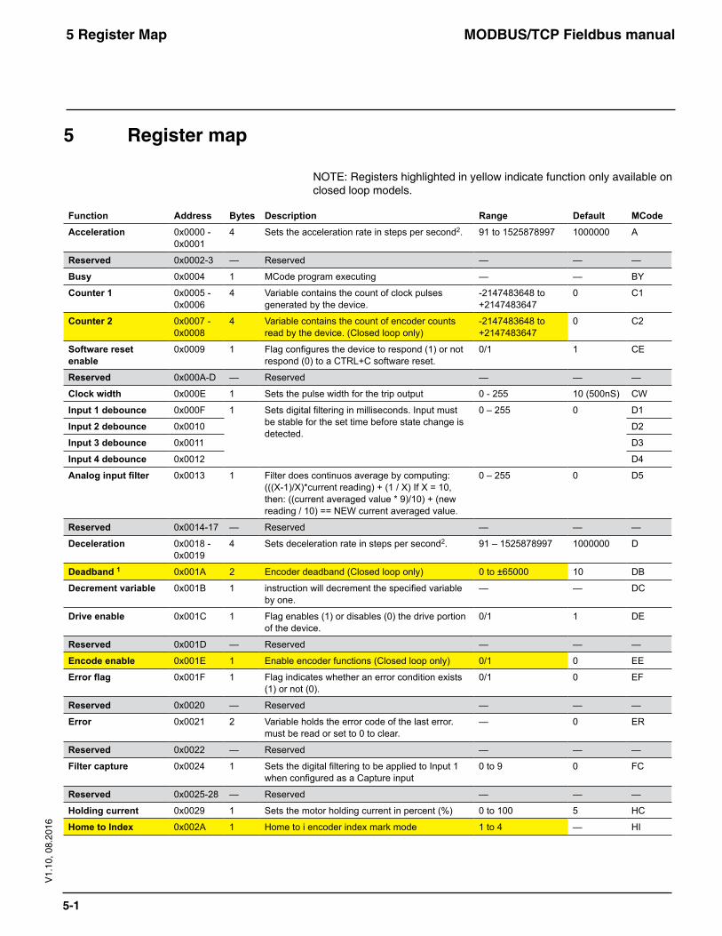
5 Register map
NOTE: Registers highlighted in yellow indicate function only available on closed loop models.
Function Address Bytes Description Range Default MCodeAcceleration 0x0000 -
0x00014 Sets the acceleration rate in steps per second2. 91 to 1525878997 1000000 A
Reserved 0x0002-3 — Reserved — — —
Busy 0x0004 1 MCode program executing — — BY
Counter 1 0x0005 - 0x0006
4 Variable contains the count of clock pulses generated by the device.
-2147483648 to +2147483647
0 C1
Counter 2 0x0007 - 0x0008
4 Variable contains the count of encoder counts read by the device. (Closed loop only)
-2147483648 to +2147483647
0 C2
Software reset enable
0x0009 1 Flag configures the device to respond (1) or not respond (0) to a CTRL+C software reset.
0/1 1 CE
Reserved 0x000A-D — Reserved — — —
Clock width 0x000E 1 Sets the pulse width for the trip output 0 - 255 10 (500nS) CW
Input 1 debounce 0x000F 1 Sets digital filtering in milliseconds. Input must be stable for the set time before state change is detected.
0 – 255 0 D1
Input 2 debounce 0x0010 D2
Input 3 debounce 0x0011 D3
Input 4 debounce 0x0012 D4
Analog input filter 0x0013 1 Filter does continuos average by computing: (((X-1)/X)*current reading) + (1 / X) If X = 10, then: ((current averaged value * 9)/10) + (new reading / 10) == NEW current averaged value.
0 – 255 0 D5
Reserved 0x0014-17 — Reserved — — —
Deceleration 0x0018 - 0x0019
4 Sets deceleration rate in steps per second2. 91 – 1525878997 1000000 D
Deadband 1 0x001A 2 Encoder deadband (Closed loop only) 0 to ±65000 10 DB
Decrement variable 0x001B 1 instruction will decrement the specified variable by one.
— — DC
Drive enable 0x001C 1 Flag enables (1) or disables (0) the drive portion of the device.
0/1 1 DE
Reserved 0x001D — Reserved — — —
Encode enable 0x001E 1 Enable encoder functions (Closed loop only) 0/1 0 EE
Error flag 0x001F 1 Flag indicates whether an error condition exists (1) or not (0).
0/1 0 EF
Reserved 0x0020 — Reserved — — —
Error 0x0021 2 Variable holds the error code of the last error. must be read or set to 0 to clear.
— 0 ER
Reserved 0x0022 — Reserved — — —
Filter capture 0x0024 1 Sets the digital filtering to be applied to Input 1 when configured as a Capture input
0 to 9 0 FC
Reserved 0x0025-28 — Reserved — — —
Holding current 0x0029 1 Sets the motor holding current in percent (%) 0 to 100 5 HC
Home to Index 0x002A 1 Home to i encoder index mark mode 1 to 4 — HI
MODBUS/TCP Fieldbus manual5 Register Map
5-2
V1.
10, 0
8.20
16
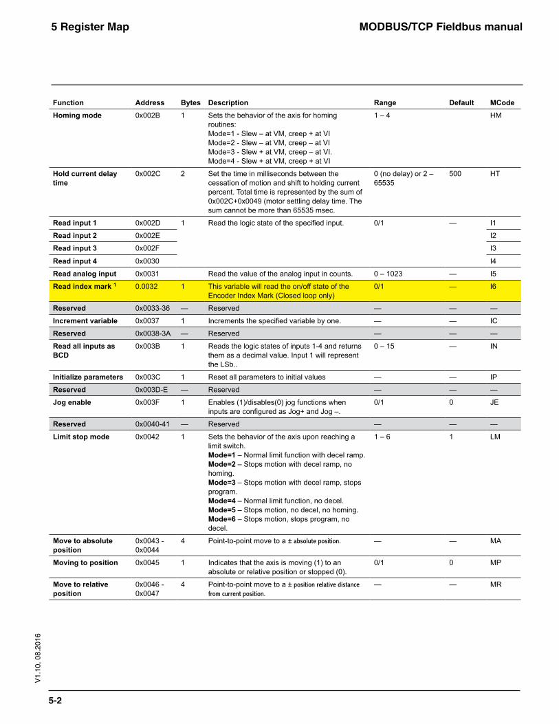
Function Address Bytes Description Range Default MCodeHoming mode 0x002B 1 Sets the behavior of the axis for homing
routines: Mode=1 - Slew – at VM, creep + at VI Mode=2 - Slew – at VM, creep – at VI Mode=3 - Slew + at VM, creep – at VI. Mode=4 - Slew + at VM, creep + at VI
1 – 4 HM
Hold current delay time
0x002C 2 Set the time in milliseconds between the cessation of motion and shift to holding current percent. Total time is represented by the sum of 0x002C+0x0049 (motor settling delay time. The sum cannot be more than 65535 msec.
0 (no delay) or 2 – 65535
500 HT
Read input 1 0x002D 1 Read the logic state of the specified input. 0/1 — I1
Read input 2 0x002E I2
Read input 3 0x002F I3
Read input 4 0x0030 I4
Read analog input 0x0031 Read the value of the analog input in counts. 0 – 1023 — I5
Read index mark 1 0.0032 1 This variable will read the on/off state of the Encoder Index Mark (Closed loop only)
0/1 — I6
Reserved 0x0033-36 — Reserved — — —
Increment variable 0x0037 1 Increments the specified variable by one. — — IC
Reserved 0x0038-3A — Reserved — — —
Read all inputs as BCD
0x003B 1 Reads the logic states of inputs 1-4 and returns them as a decimal value. Input 1 will represent the LSb..
0 – 15 — IN
Initialize parameters 0x003C 1 Reset all parameters to initial values — — IP
Reserved 0x003D-E — Reserved — — —
Jog enable 0x003F 1 Enables (1)/disables(0) jog functions when inputs are configured as Jog+ and Jog –.
0/1 0 JE
Reserved 0x0040-41 — Reserved — — —
Limit stop mode 0x0042 1 Sets the behavior of the axis upon reaching a limit switch. Mode=1 – Normal limit function with decel ramp. Mode=2 – Stops motion with decel ramp, no homing. Mode=3 – Stops motion with decel ramp, stops program. Mode=4 – Normal limit function, no decel. Mode=5 – Stops motion, no decel, no homing. Mode=6 – Stops motion, stops program, no decel.
1 – 6 1 LM
Move to absolute position
0x0043 - 0x0044
4 Point-to-point move to a ± absolute position. — — MA
Moving to position 0x0045 1 Indicates that the axis is moving (1) to an absolute or relative position or stopped (0).
0/1 0 MP
Move to relative position
0x0046 - 0x0047
4 Point-to-point move to a ± position relative distance from current position.
— — MR
MODBUS/TCP Fieldbus manual5 Register Map
5-3
V1.
10, 0
8.20
16
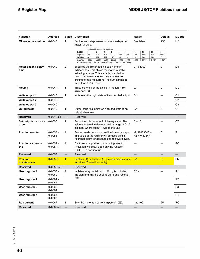
Function Address Bytes Description Range Default MCodeMicrostep resolution 0x0048 1 Set the microstep resolution in microsteps per
motor full step.See table 256 MS
Available Microsteps Per Revolution0x0048= 1 2 4 5 8 10 16 25 32 50steps/rev 200 400 800 1000 1600 2000 3200 5000 6400 100000x0048= 64 100 125 128 200 250 256 180 108 127steps/rev 12800 20000 25000 25600 40000 50000 51200 360001 216002 254003
1=0.01 deg/µstep 2=1 arc minute/µstep 3=0.001 mm/µstep
Motor settling delay time
0x0049 2 Specifies the motor settling delay time in milliseconds. This allows the motor to settle following a move. This variable is added to 0x002C to determine the total time before shifting to holding current. The sum cannot be more than 65535 msec.
0 – 65000 0 MT
Moving 0x004A 1 Indicates whether the axis is in motion (1) or stationary (0).
0/1 0 MV
Write output 1 0x004B 1 Write (set) the logic state of the specified output. 0/1 — O1
Write output 2 0x004C O2
Write output 3 0x004D O3
Output fault 0x004E 1 Output fault flag indicates a faulted state of an output when true.
0/1 0 OF
Reserved 0x004F-55 — Reserved — — —
Set outputs 1 - 4 as a group
0x0056 1 Set outputs 1-4 as one 4 bit binary value. The value is entered in decimal, with a range of 0-15 in binary where output 1 will be the LSb
0 – 15 — OT
Position counter 0x0057 - 0x0058
4 Sets or reads the axis ± position in motor steps. The value of the register will be used as the reference point for absolute and relative moves.
-2147483648 – +2147483647
0 P
Position capture at trip
0x0059 - 0x005A
4 Captures axis position during a trip event. Activation will occur upon any trip function EXCEPT a position trip.
— — PC
Reserved 0x005B — Reserved — — —
Position maintenance
0x005C 1 Enables (1) or disables (0) position maintenance functions (Closed loop only)
0/1 0 PM
Reserved 0x005D-5E — Reserved — — —
User register 1 0x005F - 0x0060
4 registers may contain up to 11 digits including the sign and may be used to store and retrieve data.
32 bit — R1
User register 2 0x0061 - 0x0062
R2
User register 3 0x0063 - 0x0064
R3
User register 4 0x0065 - 0x0066
R4
Run current 0x0067 1 Sets the motor run current in percent (%). 1 to 100 25 RC
Reserved 0x0068-75 — Reserved — — —
MODBUS/TCP Fieldbus manual5 Register Map
5-4
V1.
10, 0
8.20
16
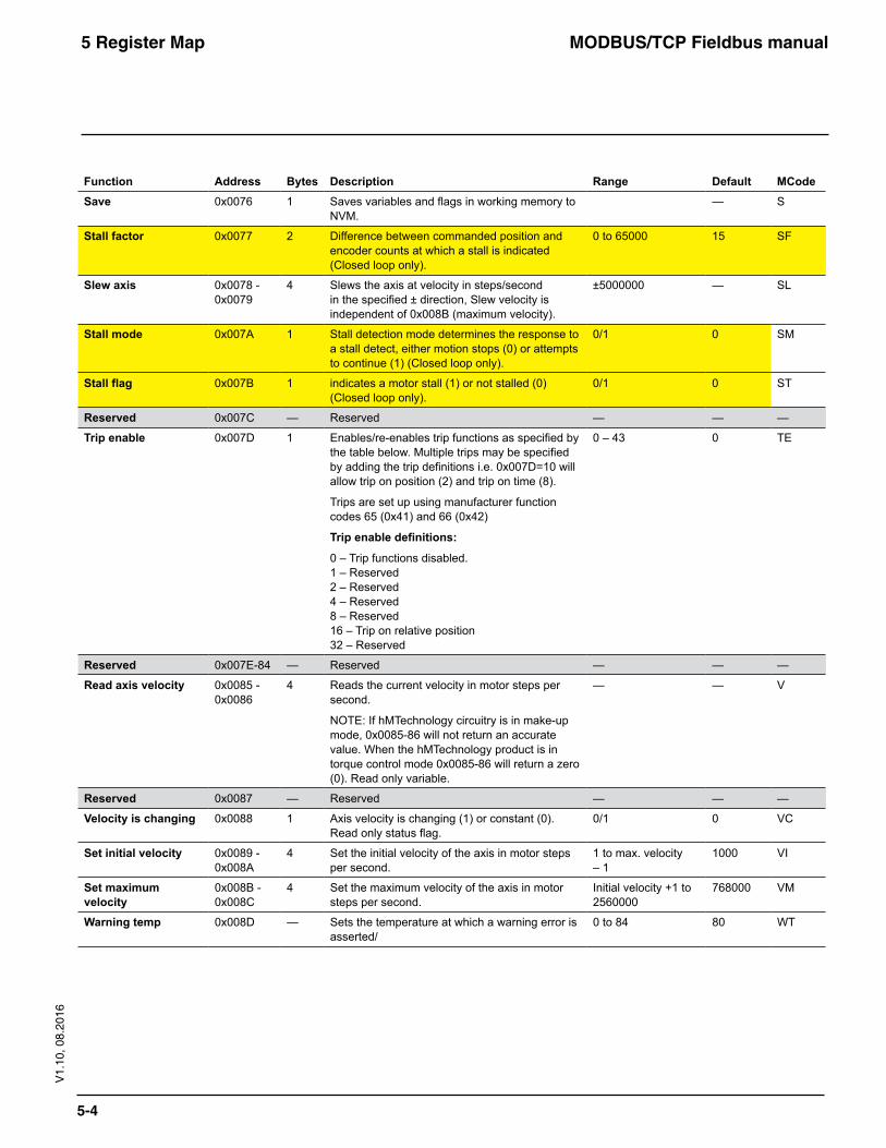
Function Address Bytes Description Range Default MCodeSave 0x0076 1 Saves variables and flags in working memory to
NVM.— S
Stall factor 0x0077 2 Difference between commanded position and encoder counts at which a stall is indicated (Closed loop only).
0 to 65000 15 SF
Slew axis 0x0078 - 0x0079
4 Slews the axis at velocity in steps/second in the specified ± direction, Slew velocity is independent of 0x008B (maximum velocity).
±5000000 — SL
Stall mode 0x007A 1 Stall detection mode determines the response to a stall detect, either motion stops (0) or attempts to continue (1) (Closed loop only).
0/1 0 SM
Stall flag 0x007B 1 indicates a motor stall (1) or not stalled (0) (Closed loop only).
0/1 0 ST
Reserved 0x007C — Reserved — — —
Trip enable 0x007D 1 Enables/re-enables trip functions as specified by the table below. Multiple trips may be specified by adding the trip definitions i.e. 0x007D=10 will allow trip on position (2) and trip on time (8).
Trips are set up using manufacturer function codes 65 (0x41) and 66 (0x42)
Trip enable definitions:
0 – Trip functions disabled. 1 – Reserved 2 – Reserved 4 – Reserved 8 – Reserved 16 – Trip on relative position 32 – Reserved
0 – 43 0 TE
Reserved 0x007E-84 — Reserved — — —
Read axis velocity 0x0085 - 0x0086
4 Reads the current velocity in motor steps per second.
NOTE: If hMTechnology circuitry is in make-up mode, 0x0085-86 will not return an accurate value. When the hMTechnology product is in torque control mode 0x0085-86 will return a zero (0). Read only variable.
— — V
Reserved 0x0087 — Reserved — — —
Velocity is changing 0x0088 1 Axis velocity is changing (1) or constant (0). Read only status flag.
0/1 0 VC
Set initial velocity 0x0089 - 0x008A
4 Set the initial velocity of the axis in motor steps per second.
1 to max. velocity – 1
1000 VI
Set maximum velocity
0x008B - 0x008C
4 Set the maximum velocity of the axis in motor steps per second.
Initial velocity +1 to 2560000
768000 VM
Warning temp 0x008D — Sets the temperature at which a warning error is asserted/
0 to 84 80 WT
MODBUS/TCP Fieldbus manual5 Register Map
5-5
V1.
10, 0
8.20
16
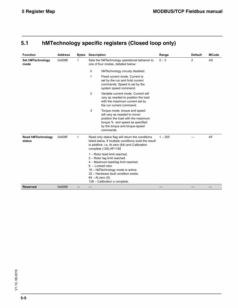
5.1 hMTechnologyspecificregisters(Closedlooponly)
Function Address Bytes Description Range Default MCodeSet hMTechnology mode
0x008E 1 Sets the hMTechnology operational behavior to one of four modes, detailed below:
0 hMTechnology circuity disabled.
1 Fixed current mode. Current is set by the run and hold current commands, Speed is set by the system speed command.
2 Variable current mode. Current will vary as needed to position the load with the maximum current set by the run current command.
3 Torque mode, torque and speed will vary as needed to move/position the load with the maximum torque % and speed as specified by the torque and torque-speed commands.
0 – 3 2 AS
Read hMTechnology status
0x008F 1 Read only status flag will return the conditions listed below, If multiple conditions exist the result is additive. i.e. At zero (64) and Calibration complete (128) AF=192
1 – Rotor lead limit reached. 2 – Rotor lag limit reached. 4 – Maximum lead/lag limit reached. 8 – Locked rotor. 16 – hMTechnology mode is active. 32 – Hardware fault condition exists. 64 – At zero (0). 128 – Calibration s complete.
1 – 255 — AF
Reserved 0x0090 — — — — —
MODBUS/TCP Fieldbus manual5 Register Map
5-6
V1.
10, 0
8.20
16
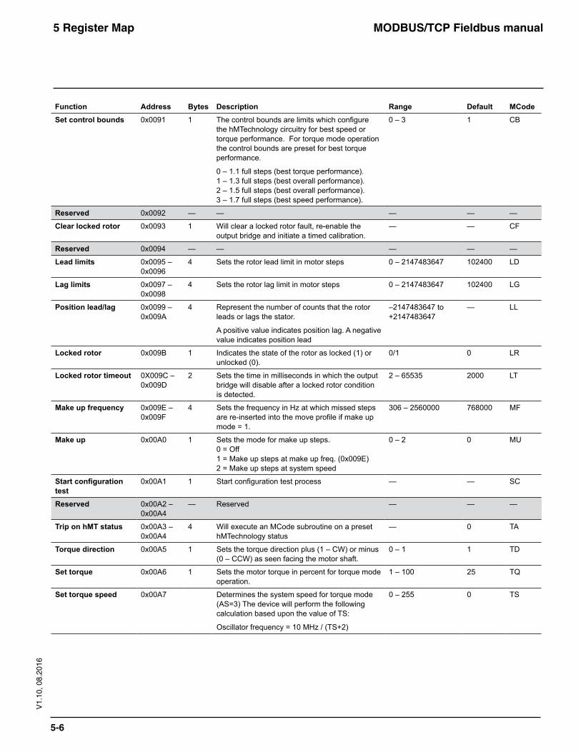
Function Address Bytes Description Range Default MCodeSet control bounds 0x0091 1 The control bounds are limits which configure
the hMTechnology circuitry for best speed or torque performance. For torque mode operation the control bounds are preset for best torque performance.
0 – 1.1 full steps (best torque performance). 1 – 1.3 full steps (best overall performance). 2 – 1.5 full steps (best overall performance). 3 – 1.7 full steps (best speed performance).
0 – 3 1 CB
Reserved 0x0092 — — — — —
Clear locked rotor 0x0093 1 Will clear a locked rotor fault, re-enable the output bridge and initiate a timed calibration.
— — CF
Reserved 0x0094 — — — — —
Lead limits 0x0095 – 0x0096
4 Sets the rotor lead limit in motor steps 0 – 2147483647 102400 LD
Lag limits 0x0097 – 0x0098
4 Sets the rotor lag limit in motor steps 0 – 2147483647 102400 LG
Position lead/lag 0x0099 – 0x009A
4 Represent the number of counts that the rotor leads or lags the stator.
A positive value indicates position lag. A negative value indicates position lead
–2147483647 to +2147483647
— LL
Locked rotor 0x009B 1 Indicates the state of the rotor as locked (1) or unlocked (0).
0/1 0 LR
Locked rotor timeout 0X009C – 0x009D
2 Sets the time in milliseconds in which the output bridge will disable after a locked rotor condition is detected.
2 – 65535 2000 LT
Make up frequency 0x009E – 0x009F
4 Sets the frequency in Hz at which missed steps are re-inserted into the move profile if make up mode = 1.
306 – 2560000 768000 MF
Make up 0x00A0 1 Sets the mode for make up steps. 0 = Off 1 = Make up steps at make up freq. (0x009E) 2 = Make up steps at system speed
0 – 2 0 MU
Start configuration test
0x00A1 1 Start configuration test process — — SC
Reserved 0x00A2 – 0x00A4
— Reserved — — —
Trip on hMT status 0x00A3 – 0x00A4
4 Will execute an MCode subroutine on a preset hMTechnology status
— 0 TA
Torque direction 0x00A5 1 Sets the torque direction plus (1 – CW) or minus (0 – CCW) as seen facing the motor shaft.
0 – 1 1 TD
Set torque 0x00A6 1 Sets the motor torque in percent for torque mode operation.
1 – 100 25 TQ
Set torque speed 0x00A7 Determines the system speed for torque mode (AS=3) The device will perform the following calculation based upon the value of TS:
Oscillator frequency = 10 MHz / (TS+2)
0 – 255 0 TS
MODBUS/TCP Fieldbus manual5 Register Map
5-7
V1.
10, 0
8.20
16
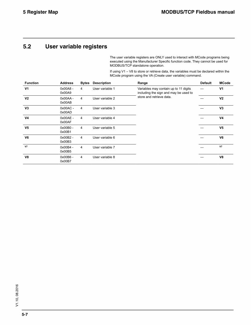
5.2 User variable registers
The user variable registers are ONLY used to interact with MCode programs being executed using the Manufacturer Specific function code. They cannot be used for MODBUS/TCP standalone operation.
If using V1 – V8 to store or retrieve data, the variables must be declared within the MCode program using the VA (Create user variable) command.
Function Address Bytes Description Range Default MCodeV1 0x00A8 -
0x00A94 User variable 1 Variables may contain up to 11 digits
including the sign and may be used to store and retrieve data.
— V1
V2 0x00AA - 0x00AB
4 User variable 2 — V2
V3 0x00AC - 0x00AD
4 User variable 3 — V3
V4 0x00AE - 0x00AF
4 User variable 4 — V4
V5 0x00B0 - 0x00B1
4 User variable 5 — V5
V6 0x00B2 - 0x00B3
4 User variable 6 — V6
V7 0x00B4 - 0x00B5
4 User variable 7 — V7
V8 0x00B6 - 0x00B7
4 User variable 8 — V8
MODBUS/TCP Fieldbus manual6 TCP/IP Configuration Utility
6-1
V1.
10, 0
8.20
16
6 TCP/IPConfigurationUtility
The TCP/IP configuration Utility is used to configure and rest the func-tionality of Lexium MDrive Ethernet units.
For installation and usage instructions see the Lexium MDrive Software Suite Manual available online at:
http://motion.schneider-electric.com

WARRANTYReference the web site at www.motion.schneider-electric.com for the latest warranty and product information.

© Schneider Electric Motion USA All Rights Reserved. Product Disclaimer and most recent product information online.
Schneider Electric Motion USA 370 N. Main Street Owing to changes in standards and equipment, the characteristics given in the text and images Marlborough, CT 06447 USA in this document are not binding until they have been confirmed with us. Print: Schneider Electric Motion USA www.motion.schneider-electric.com Photos: Schneider Electric Motion USA
Date : 08 / 2016
USA SALES OFFICES East Region Tel. 610-573-9655e-mail: [email protected] RegionTel. 860-368-9703e-mail: [email protected] Region Tel. 630-267-3302 e-mail: [email protected] Region Tel. 602-578-7201 e-mail: [email protected]
EUROPEAN SALES MANAGEMENTTel. +33/4 7256 5113 – Fax +33/4 7838 1537 e-mail: [email protected]
TECHNICAL SUPPORT Tel. +00 (1) 860-295-6102 – Fax +00 (1) 860-295-6107e-mail: [email protected]