Embed Size (px)
Citation preview
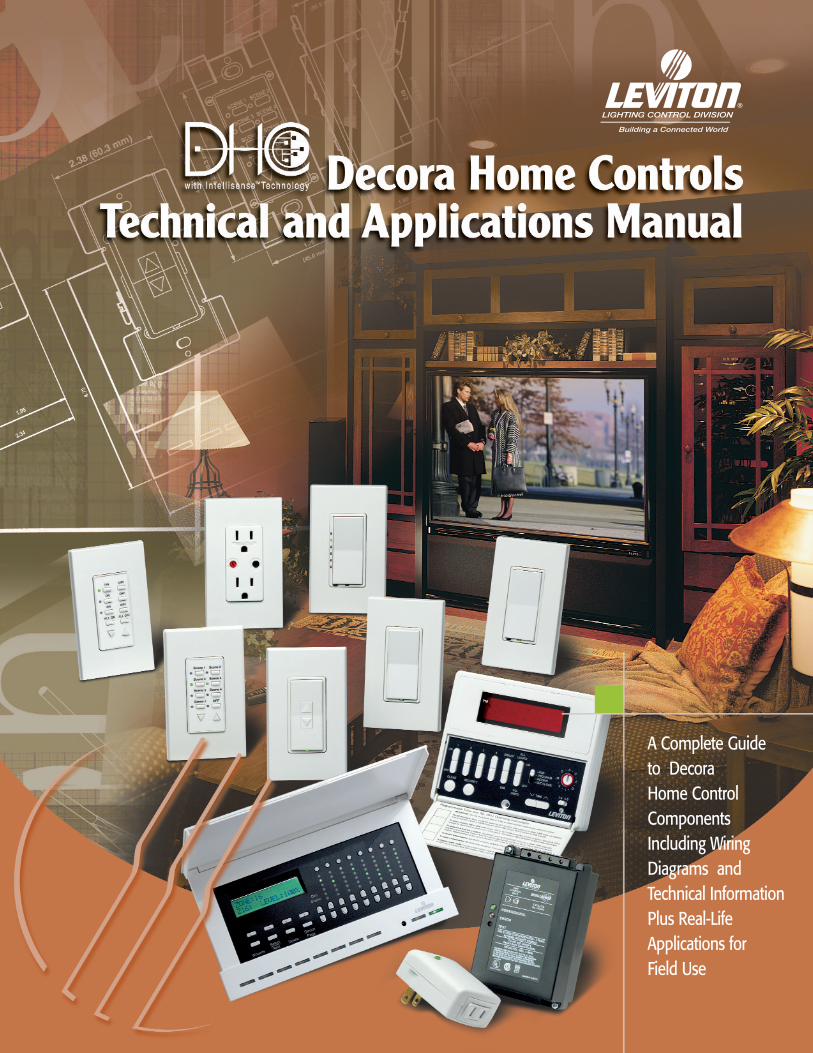
A Complete Guide to Decora Home Control ComponentsIncluding WiringDiagrams andTechnical InformationPlus Real-LifeApplications for Field Use

TABLE OF CONTENTS
How DHC Components Operate . . . . . . . . . . . . . . . . . . . . . . . . . . . . . . . . . . . . . . . . . . . . . . . . . . . . . . i–ivIntroduction to DHC . . . . . . . . . . . . . . . . . . . . . . . . . . . . . . . . . . . . . . . . . . . . . . . . . . . . . . . . . . . . . . . . . . . . . . . . . . . . . . . . . . . . . .iThe DHC Address/Command Signal . . . . . . . . . . . . . . . . . . . . . . . . . . . . . . . . . . . . . . . . . . . . . . . . . . . . . . . . . . . . . . . . . . . . . . .iiiTypical DHC Specification/Decora Designer Styling . . . . . . . . . . . . . . . . . . . . . . . . . . . . . . . . . . . . . . . . . . . . . . . . . . . . . . . . . . .iv
Receivers . . . . . . . . . . . . . . . . . . . . . . . . . . . . . . . . . . . . . . . . . . . . . . . . . . . . . . . . . . . . . . . . . . . . . . . R1–R7HCM06-1SW 600 Watt Scene-Capable Dimming Wall Switch Receiver with One-Button Programming . . . . . . . . . . . . . .R1HCM10-1SW 1000 Watt Scene-Capable Dimming Wall Switch Receiver with One-Button Programming . . . . . . . . . . . . .R1HCM06-1DW 600 Watt Scene-Capable Dimming Wall Switch Receiver with One-Button Programming and LED’s . . . . .R2HCM10-1DW 1000 Watt Scene-Capable Dimming Wall Switch Receiver with One-Button Programming and LED’s . . . .R2HCM06-1TW 600 Watt Scene-Capable Dimming Wall Switch Receiver with One-Button Programming, 2-Way
Communication and LED’s . . . . . . . . . . . . . . . . . . . . . . . . . . . . . . . . . . . . . . . . . . . . . . . . . . . . . . . . . . . . . . .R3HCM10-1TW 1000 Watt Scene-Capable Dimming Wall Switch Receiver with One-Button Programming, 2-Way
Communication and LED’s . . . . . . . . . . . . . . . . . . . . . . . . . . . . . . . . . . . . . . . . . . . . . . . . . . . . . . . . . . . . . . .R3HCS08-1TW 8 Amp Scene-Capable ON/OFF Electronic Wall Switch Receiver with One-Button Programming and
2-Way Communication . . . . . . . . . . . . . . . . . . . . . . . . . . . . . . . . . . . . . . . . . . . . . . . . . . . . . . . . . . . . . . . . . . .R4HCS10-1SW 10 Amp Scene-Capable Wall Switch Receiver with One-Button Programming . . . . . . . . . . . . . . . . . . . . . .R5HCP03-10W Scene-Capable Dimming Plug-In Lamp Module with One-Button Programming . . . . . . . . . . . . . . . . . . . . .R6MS00R-10 Multi-Remote Dimming Wall Switch for Multi-Location Scene-Capable Wall Switches . . . . . . . . . . . . . . . . .R7DPSPE112/212 2000W/2000VA Power Extender Modules . . . . . . . . . . . . . . . . . . . . . . . . . . . . . . . . . . . . . . . . . . . . . . . . . . . .R7
Receivers . . . . . . . . . . . . . . . . . . . . . . . . . . . . . . . . . . . . . . . . . . . . . . . . . . . . . . . . . . . . . . . . . . . . . . R8–R126383-WI Multi-Location Dimming Switch . . . . . . . . . . . . . . . . . . . . . . . . . . . . . . . . . . . . . . . . . . . . . . . . . . . . . . . . . . . .R86291-WI Single-Pole Wall Switch . . . . . . . . . . . . . . . . . . . . . . . . . . . . . . . . . . . . . . . . . . . . . . . . . . . . . . . . . . . . . . . . . .R86293-WI 3-Way (Multi-Location) Wall Switch . . . . . . . . . . . . . . . . . . . . . . . . . . . . . . . . . . . . . . . . . . . . . . . . . . . . . . . . .R86294 Remote Wall Switch . . . . . . . . . . . . . . . . . . . . . . . . . . . . . . . . . . . . . . . . . . . . . . . . . . . . . . . . . . . . . . . . . . . . .R96371-I Double-Pole Wall Switch . . . . . . . . . . . . . . . . . . . . . . . . . . . . . . . . . . . . . . . . . . . . . . . . . . . . . . . . . . . . . . . . .R96337 Universal Low-Voltage Module . . . . . . . . . . . . . . . . . . . . . . . . . . . . . . . . . . . . . . . . . . . . . . . . . . . . . . . . . . .R106227 Split Duplex Receptacle . . . . . . . . . . . . . . . . . . . . . . . . . . . . . . . . . . . . . . . . . . . . . . . . . . . . . . . . . . . . . . . .R116280 Duplex Receptacle . . . . . . . . . . . . . . . . . . . . . . . . . . . . . . . . . . . . . . . . . . . . . . . . . . . . . . . . . . . . . . . . . . . .R116296/6298 Single Receptacles . . . . . . . . . . . . . . . . . . . . . . . . . . . . . . . . . . . . . . . . . . . . . . . . . . . . . . . . . . . . . . . . . . . .R116375/6376 Fixture Relay Modules . . . . . . . . . . . . . . . . . . . . . . . . . . . . . . . . . . . . . . . . . . . . . . . . . . . . . . . . . . . . . . . . . .R12
Controllers featuring 2-Way Communication . . . . . . . . . . . . . . . . . . . . . . . . . . . . . . . . . . . . . . . . C1–C5HCCPG-1TW DHC Toscana™ Deluxe Programmer . . . . . . . . . . . . . . . . . . . . . . . . . . . . . . . . . . . . . . . . . . . . . . . . . . . . . . . .C1HCC10-1TW One-Address ON/OFF Wall Switch Controller . . . . . . . . . . . . . . . . . . . . . . . . . . . . . . . . . . . . . . . . . . . . . . . . .C2HCC1A-1TW ALL LIGHTS ON/ALL OFF Wall Switch Controller . . . . . . . . . . . . . . . . . . . . . . . . . . . . . . . . . . . . . . . . . . . . . .C2HCC1D-1TW One-Address Dimming Wall Switch Controller . . . . . . . . . . . . . . . . . . . . . . . . . . . . . . . . . . . . . . . . . . . . . . . .C3HCC2D-1TW Two-Address Dimming Wall Switch Controller . . . . . . . . . . . . . . . . . . . . . . . . . . . . . . . . . . . . . . . . . . . . . . . .C4HCC3D-1TW Three-Address Dimming Wall Switch Controller . . . . . . . . . . . . . . . . . . . . . . . . . . . . . . . . . . . . . . . . . . . . . . .C4HCC4D-1TW Four-Address Dimming Wall Switch Controller . . . . . . . . . . . . . . . . . . . . . . . . . . . . . . . . . . . . . . . . . . . . . . . .C4HCC4A-1TW Three-Address Dimming, ALL LIGHTS ON/ALL OFF Wall Switch Controller . . . . . . . . . . . . . . . . . . . . . . . .C4HCCS7-1TW Seven-Scene Dimming Wall Switch Controller . . . . . . . . . . . . . . . . . . . . . . . . . . . . . . . . . . . . . . . . . . . . . . . .C5
Controllers . . . . . . . . . . . . . . . . . . . . . . . . . . . . . . . . . . . . . . . . . . . . . . . . . . . . . . . . . . . . . . . . . . . . . C6–C916400 Uni-Base Wall Mounted Controller Body for 16450 Controller Faces . . . . . . . . . . . . . . . . . . . . . . . . . . . . . .C616450 Uni-Base Controller Faces with Scene Control Models . . . . . . . . . . . . . . . . . . . . . . . . . . . . . . . . . . . . . . . . .C66312 Basic Wall-Mounted Programmer . . . . . . . . . . . . . . . . . . . . . . . . . . . . . . . . . . . . . . . . . . . . . . . . . . . . . . . . . .C76320 Table Top Controller . . . . . . . . . . . . . . . . . . . . . . . . . . . . . . . . . . . . . . . . . . . . . . . . . . . . . . . . . . . . . . . . . . . . .C76313 Hand-Held Remote Controller . . . . . . . . . . . . . . . . . . . . . . . . . . . . . . . . . . . . . . . . . . . . . . . . . . . . . . . . . . . . .C86314-W Remote Transceiver . . . . . . . . . . . . . . . . . . . . . . . . . . . . . . . . . . . . . . . . . . . . . . . . . . . . . . . . . . . . . . . . . . . . .C86332 Wireless Key Chain Remote Controller . . . . . . . . . . . . . . . . . . . . . . . . . . . . . . . . . . . . . . . . . . . . . . . . . . . . . .C86417 Passive Infrared Controller . . . . . . . . . . . . . . . . . . . . . . . . . . . . . . . . . . . . . . . . . . . . . . . . . . . . . . . . . . . . . . .C9
Note: Because Leviton engages in a continuous program of product improvement, data in this catalog is subject to changewithout notice.©2002 Leviton Manufacturing Co., Inc. All rights reserved.

TABLE OF CONTENTS
Network Integrity Products . . . . . . . . . . . . . . . . . . . . . . . . . . . . . . . . . . . . . . . . . . . . . . . . . . . . . . . N1–N2HCA02-10E System Amplifier Module (HCS/HCM/HCC Series) . . . . . . . . . . . . . . . . . . . . . . . . . . . . . . . . . . . . . . . . . . . .N16201 System Amplifier Module (16400/16450 Series) . . . . . . . . . . . . . . . . . . . . . . . . . . . . . . . . . . . . . . . . . . . . . .N151120-1 Panel-Mounted Surge Protective Device . . . . . . . . . . . . . . . . . . . . . . . . . . . . . . . . . . . . . . . . . . . . . . . . . . . .N151120-3 Panel-Mounted Surge Protective Device . . . . . . . . . . . . . . . . . . . . . . . . . . . . . . . . . . . . . . . . . . . . . . . . . . . .N251120-3R Panel-Mounted Surge Protective Device . . . . . . . . . . . . . . . . . . . . . . . . . . . . . . . . . . . . . . . . . . . . . . . . . . . .N251120-PTC Panel-Mounted Surge Protective Device . . . . . . . . . . . . . . . . . . . . . . . . . . . . . . . . . . . . . . . . . . . . . . . . . . . .N2
Ancillary DHC Devices . . . . . . . . . . . . . . . . . . . . . . . . . . . . . . . . . . . . . . . . . . . . . . . . . . . . . . . . . . . . . .A16284 Multi-Phase Blocking Coupler . . . . . . . . . . . . . . . . . . . . . . . . . . . . . . . . . . . . . . . . . . . . . . . . . . . . . . . . . . . . .A16285 Signal Attenuator . . . . . . . . . . . . . . . . . . . . . . . . . . . . . . . . . . . . . . . . . . . . . . . . . . . . . . . . . . . . . . . . . . . . . . .A16287 Noise Block . . . . . . . . . . . . . . . . . . . . . . . . . . . . . . . . . . . . . . . . . . . . . . . . . . . . . . . . . . . . . . . . . . . . . . . . . . .A16288 Plug-In Noise Filter . . . . . . . . . . . . . . . . . . . . . . . . . . . . . . . . . . . . . . . . . . . . . . . . . . . . . . . . . . . . . . . . . . . . . .A16289 In-Line Noise Reducer . . . . . . . . . . . . . . . . . . . . . . . . . . . . . . . . . . . . . . . . . . . . . . . . . . . . . . . . . . . . . . . . . . .A1
Product Testing . . . . . . . . . . . . . . . . . . . . . . . . . . . . . . . . . . . . . . . . . . . . . . . . . . . . . . . . . . . . . . . . . . . .PT16386 Signal Strength Indicator . . . . . . . . . . . . . . . . . . . . . . . . . . . . . . . . . . . . . . . . . . . . . . . . . . . . . . . . . . . . . . . .PT1
DHC Trouble-Shooting Guide . . . . . . . . . . . . . . . . . . . . . . . . . . . . . . . . . . . . . . . . . . . . . . . . . . . .TS1–TS9Introduction . . . . . . . . . . . . . . . . . . . . . . . . . . . . . . . . . . . . . . . . . . . . . . . . . . . . . . . . . . . . . . . . . . . . . . . . . . . . . . . .TS1-TS2Troubleshooting Procedure Chart . . . . . . . . . . . . . . . . . . . . . . . . . . . . . . . . . . . . . . . . . . . . . . . . . . . . . . . . . . . . . . . . . . . . . . . .TS3Checklist Procedures/Necessary Equipment . . . . . . . . . . . . . . . . . . . . . . . . . . . . . . . . . . . . . . . . . . . . . . . . . . . . . . . . . . . . . . .TS4Confirming the Operation of Transmitters and Switches . . . . . . . . . . . . . . . . . . . . . . . . . . . . . . . . . . . . . . . . . . . . . . . . . .TS5-TS7Ensuring Signal Quality . . . . . . . . . . . . . . . . . . . . . . . . . . . . . . . . . . . . . . . . . . . . . . . . . . . . . . . . . . . . . . . . . . . . . . . . . . . .TS7-TS8Electronic Noise Interference . . . . . . . . . . . . . . . . . . . . . . . . . . . . . . . . . . . . . . . . . . . . . . . . . . . . . . . . . . . . . . . . . . . . . . .TS8-TS9
DHC Application . . . . . . . . . . . . . . . . . . . . . . . . . . . . . . . . . . . . . . . . . . . . . . . . . . . . . . . . . . . . .AP1-AP12DHC Suggested Application Layouts . . . . . . . . . . . . . . . . . . . . . . . . . . . . . . . . . . . . . . . . . . . . . . . . . . . . . . . . . . . . . . . .AP1-AP12
Technical Section . . . . . . . . . . . . . . . . . . . . . . . . . . . . . . . . . . . . . . . . . . . . . . . . . . . . . . . . . . . . . . .T1–T15Wiring Diagrams . . . . . . . . . . . . . . . . . . . . . . . . . . . . . . . . . . . . . . . . . . . . . . . . . . . . . . . . . . . . . . . . . . . . . . . . . . . . . . . . . . .T1-T8Dimensional Diagrams . . . . . . . . . . . . . . . . . . . . . . . . . . . . . . . . . . . . . . . . . . . . . . . . . . . . . . . . . . . . . . . . . . . . . . . . . . . . . .T9-T15
DHC Warranty . . . . . . . . . . . . . . . . . . . . . . . . . . . . . . . . . . . . . . . . . . . . . . . . . . . . . . . .Inside Back Cover

i
Decora Home Controls Providing automated control of mood-setting
lighting scenes (macros), time-set On-Off lighting control and automated appliance control, while allowing manual control
with no adverse effects on programming.
Leviton’s Decora Home Controls powerline carriercomponents can provide any home with programmedor manual remote control of lighting and appliances.DHC controllers and receivers can be integratedon a large scale to provide a full range of homeautomation benefits, while offering economicalalternatives to many difficult AC wiring applications.
Decora Home Controls offer maximum flexibilitybecause controller and receiver units use thehome’s existing AC wiring as the basis for a powerfulcontrol network. Switching signals are sent
throughout the network in response to user-devisedprograms, manual control or remote sensor input.Components are as easy to install as standardswitches and receptacles. They are designed,manufactured and tested to meet high performancestandards and are backed by Leviton’s LimitedTwo-Year Warranty.
This manual presents a complete guide to DecoraHome Controls (DHC) components includingwiring diagrams and technical information, plusreal-life applications for field use.
INTRODUCTION TO DHC
ii
DECORA HOME CONTROLS TECHNICAL AND APPLICATIONS MANUAL
How DHC Components OperateThe DHC System
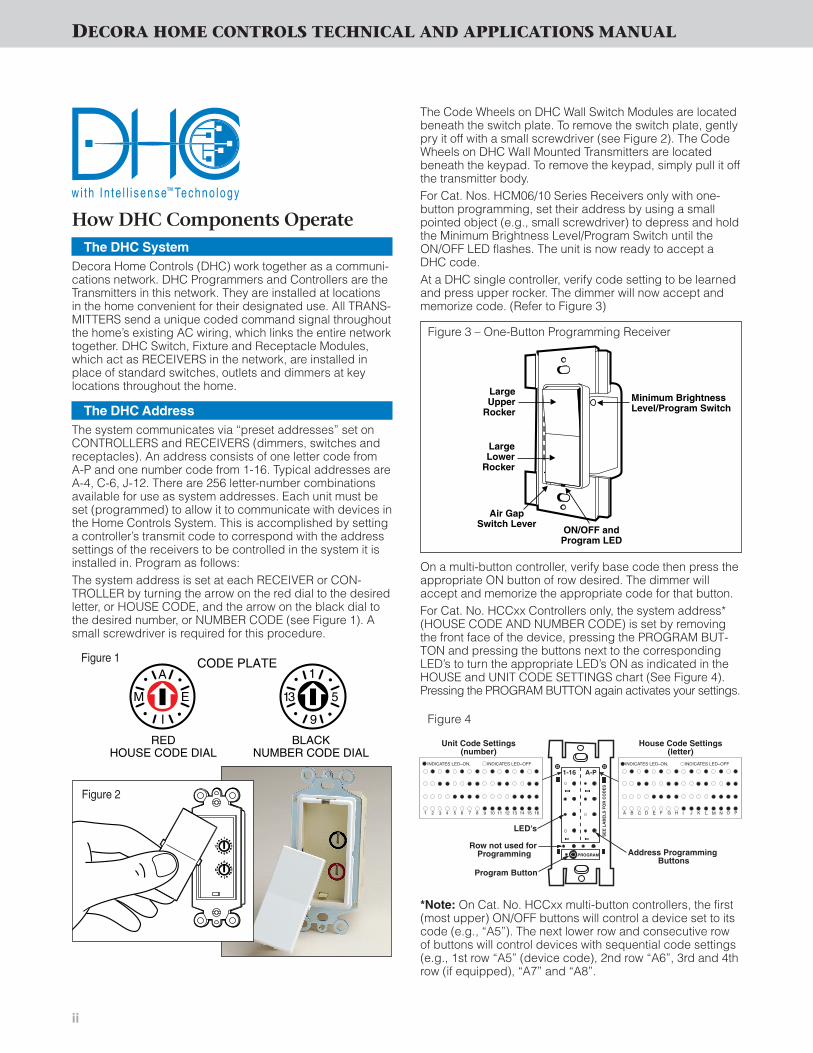
Decora Home Controls (DHC) work together as a communi-cations network. DHC Programmers and Controllers are theTransmitters in this network. They are installed at locationsin the home convenient for their designated use. All TRANS-MITTERS send a unique coded command signal throughoutthe home’s existing AC wiring, which links the entire networktogether. DHC Switch, Fixture and Receptacle Modules,which act as RECEIVERS in the network, are installed inplace of standard switches, outlets and dimmers at keylocations throughout the home.
The DHC AddressThe system communicates via “preset addresses” set onCONTROLLERS and RECEIVERS (dimmers, switches andreceptacles). An address consists of one letter code fromA-P and one number code from 1-16. Typical addresses areA-4, C-6, J-12. There are 256 letter-number combinationsavailable for use as system addresses. Each unit must beset (programmed) to allow it to communicate with devices inthe Home Controls System. This is accomplished by settinga controller’s transmit code to correspond with the addresssettings of the receivers to be controlled in the system it isinstalled in. Program as follows:The system address is set at each RECEIVER or CON-TROLLER by turning the arrow on the red dial to the desiredletter, or HOUSE CODE, and the arrow on the black dial tothe desired number, or NUMBER CODE (see Figure 1). Asmall screwdriver is required for this procedure.
A
EM
I
1
513
9
CODE PLATE
REDHOUSE CODE DIAL
BLACKNUMBER CODE DIAL
The Code Wheels on DHC Wall Switch Modules are locatedbeneath the switch plate. To remove the switch plate, gentlypry it off with a small screwdriver (see Figure 2). The CodeWheels on DHC Wall Mounted Transmitters are locatedbeneath the keypad. To remove the keypad, simply pull it offthe transmitter body.For Cat. Nos. HCM06/10 Series Receivers only with one-button programming, set their address by using a smallpointed object (e.g., small screwdriver) to depress and holdthe Minimum Brightness Level/Program Switch until theON/OFF LED flashes. The unit is now ready to accept aDHC code.At a DHC single controller, verify code setting to be learnedand press upper rocker. The dimmer will now accept andmemorize code. (Refer to Figure 3)
On a multi-button controller, verify base code then press theappropriate ON button of row desired. The dimmer willaccept and memorize the appropriate code for that button.For Cat. No. HCCxx Controllers only, the system address*(HOUSE CODE AND NUMBER CODE) is set by removingthe front face of the device, pressing the PROGRAM BUT-TON and pressing the buttons next to the correspondingLED’s to turn the appropriate LED’s ON as indicated in theHOUSE and UNIT CODE SETTINGS chart (See Figure 4).Pressing the PROGRAM BUTTON again activates your settings.
*Note: On Cat. No. HCCxx multi-button controllers, the first(most upper) ON/OFF buttons will control a device set to itscode (e.g., “A5”). The next lower row and consecutive rowof buttons will control devices with sequential code settings(e.g., 1st row “A5” (device code), 2nd row “A6”, 3rd and 4throw (if equipped), “A7” and “A8”.
Figure 1
1
5
9
13
A
E
I
M
Figure 2
LargeUpper
Rocker
Air GapSwitch Lever
ON/OFF andProgram LED
LargeLower
Rocker
Minimum BrightnessLevel/Program Switch
Program Button
1-16 A-P
LED's
Unit Code Settings (number)
House Code Settings (letter)
Address Programming Buttons
PROGRAM
SE
E L
AB
EL
S F
OR
CO
DE
S
INDICATES LED–ON, INDICATES LED–OFF
1 2 3 4 5 6 7 8 9 10 11 12 13 14 15 16
INDICATES LED–ON, INDICATES LED–OFFINDICATES LED–ON, INDICATES LED–OFF
A B C D E F G H I J K L M N O P
Row not used for Programming
Figure 3 – One-Button Programming Receiver
Figure 4

iii
The DHC Scene
A scene is a collection of preset levels across a number of dif-ferent DHC addresses. Scenes are a convenience to thehomeowner, especially in larger homes where many loads onthe same house code can now be controlled from a singlelocation with a single key-press. So, for example, devices onaddresses A1-A16 can be made to go to some predeter-mined level(s) with a single key-press.
Originally, scenes were designed to increase the reliability of ahome controls system where typically macros had previouslybeen used. They offer increased reliability in three ways. First,Leviton Scene Controls are a distributed system. They are notprone to the failure of any one particular component or circuitbreaker as with a macro controller. Second, scenes give animmediate response. They use a single command, are simplerand are inherently more reliable. Third, exclusive Intellisense™Technology gives extra support to scene commands in aDHC system.
Each Scene Capable DHC Receiver can learn up to 64scenes on each house code. The HCCS7-1TW SceneController can control up to seven of these scenes. The DHCToscana™ Deluxe Programmer can access all the scenes.The DHC Toscana Deluxe Programmer can also generatemacros and span scenes across more than one house code.
Scene Programming (Cat. No. HCCS7-1TW Scene Controller)
For Cat. No. HCCS7-1TW Scene Controller only, after settingthe system address, to set a scene, simply press and hold aSCENE BUTTON to be programmed for five seconds, adjustlight levels on all controlled Scene-Capable Receivers andpress the SCENE BUTTON again to end programming.
Cat. No. HCCS7-1TW
Program Button
1-16 A-P
LED's
Unit Code Settings (number)
House Code Settings (letter)
Address Programming Buttons
PROGRAM
SE
E L
AB
EL
S F
OR
CO
DE
S
INDICATES LED–ON, INDICATES LED–OFF
1 2 3 4 5 6 7 8 9 10 11 12 13 14 15 16
INDICATES LED–ON, INDICATES LED–OFFINDICATES LED–ON, INDICATES LED–OFF
A B C D E F G H I J K L M N O P
Row not used for Programming
The DHC Command Signal
When activated, either manually or automatically in responseto a user-programmed schedule, DHC CONTROLLERS senda 5-volt, 121 kHz series of pulses, called the “command signal”, at the zero crossing of the 60 cycle AC power curve(see Figure 6). CONTROLLERS then repeat the command asecond time for added assurance. By timing the coded transmission so that it appears in the zero crossing position,the integrity of the command signal is protected from possi-ble interference by AC line disturbances.
The command signal contains a specific address code and aperformance function code (ON, OFF, DIM, BRIGHTEN, ALLLIGHTS ON, ALL OFF). DHC CONTROLLERS can sendcommand signals to all or just a selected group of systemaddresses, depending on the particular model (see PROD-UCT LISTING section for details). All Wall Mounted Control-lers will retain command signal transmission if a commandfrom another controller is in progress on the AC power lines.When the line becomes clear, the wall units will then transmit.
All DHC RECEIVERS monitor the AC power line constantly,“listening” for a command signal. When one or a group ofRECEIVERS “hears” its specific address, it responds by performing the designated dimming or switching function.The command signal can travel a considerable distance andstill activate a RECEIVER, if no electrical loads generatinginterference are present to dissipate the signal strength.
No more than 4 Controllers should be on the same ACbranch circuit, since this can reduce signal strength considerably. (Modules featuring Leviton’s exclusiveIntellisense™ Technology enjoy reduced line noise interference without compromising system sensitivityand operate with maximum reliability.)
To ensure that no signal crossover takes place betweenneighboring DHC installations, dwellings that share the samesecondary feed from the utility company should use differentHouse Codes to prevent interference. Other special situa-tions that may distort or block the signal are discussed atlength in the Troubleshooting Guide section.
Frame
Strap
SnapsPush in 2 Locations
DECORA HOME CONTROLS TECHNICAL AND APPLICATIONS MANUAL
Figure 5
Cat No. HCCS7-1TW
120 kHz
Sending and receiving signal
0
SINE WAVE WITH120 KHZ SUPERIMPOSED
Figure 6
Note: Always follow closely the wiring diagrams andinstructions included with each Leviton DHC device.
iv
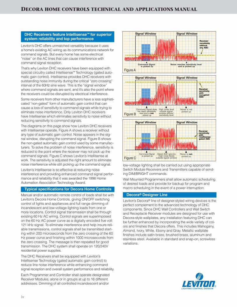
Leviton’s DHC offers unmatched versatility because it uses a home’s existing AC wiring as its communications network forcommand signals. But every home has some electrical“noise” on the AC lines that can cause interference with command signal reception.
That’s why Leviton DHC receivers have been equipped withspecial circuitry called Intellisense™ Technology (gated auto-matic gain control). Intellisense provides DHC receivers withoutstanding noise immunity during the critical “zero crossing”interval of the 60Hz sine wave. This is the “signal window”where command signals are sent, and it’s also the point wherethe receivers could be disrupted by electrical interference.
Some receivers from other manufacturers have a less sophisti-cated “non-gated” form of automatic gain control that cancause a loss of sensitivity to command signals while trying toeliminate noise interference. Only Leviton DHC receivers have Intellisense which eliminates sensitivity to noise withoutreducing sensitivity to command signals.
The diagrams on this page show how Leviton DHC receiverswith Intellisense operate. Figure A shows a receiver withoutany type of automatic gain control. Noise appears in the sig-nal window, disrupting the command signal. Figure B showsthe non-gated automatic gain control used by some manufac-turers. To solve the problem of noise interference, sensitivity isreduced to the point where the receiver may not pick up thecommand signals. Figure C shows Leviton’s Intellisense atwork. The sensitivity is adjusted the right amount to eliminatenoise interference while still picking up the command signal.
Leviton’s Intellisense is so effective at reducing noise interference and providing enhanced command signal perfor-mance and reliability that it was awarded the 1998 HomeAutomation Association Technology Award.
Typical specifications for Decora Home Controls
Manual and/or automatic remote control of loads shall be withLeviton’s Decora Home Controls, giving ON/OFF switchingcontrol of lights and appliances and full range dimming ofincandescent and low-voltage lighting loads from one ormore locations. Control signal transmission shall be throughexisting 60 Hz AC wiring. Control signals are superimposedon the 60 Hz AC power curve as a digitally encoded five volt121 kHz signal. To eliminate interference and help insure reli-able transmissions, control signals shall be transmitted start-ing within 200 microseconds from the zero crossing of the 60Hz power curve and finishing within 1000 microseconds fromthe zero crossing. The message is then repeated for goodtransmission. The DHC system shall operate on 120/240Vresidential power supplies.
The DHC Receivers shall be equipped with Leviton’sIntellisense Technology (gated automatic gain control) toreduce line noise interference while enhancing commandsignal reception and overall system performance and reliability.
Each Programmer and Controller shall operate designatedReceiver Modules, alone or in groups at up to 16 differentaddresses. Dimming of all controlled incandescent and/or
Signal Window Signal Window
Receiversensitivitywithout any AGC
Receiversensitivitywithout any AGC
Noise reaches sensitivity level and is picked up
Command Signal is picked up
Signal Window Signal Window
Receiversensitivitywith non-gatedAGC
Receiversensitivitywith non-gatedAGC
Noise is notpicked up
Command Signal does not reach sensitivity
level and is not picked up
High noise leveloutside signal window effects sensitivity level
Signal Window Signal Window
Receiversensitivitywith Intellisensegated AGC
Receiversensitivitywith Intellisensegated AGC
Noise is notpicked up
Command Signal is picked up
Gated AGC ignoresHigh noise levels
outside signal window
low-voltage lighting shall be carried out using appropriateSwitch Module Receivers and Transmitters capable of send-ing DIM/BRIGHT commands.
Wall Mounted Programmers shall allow automatic schedulingof desired loads and provide for backup for program andmacro scheduling in the event of a power interruption.
Decora® Designer Line
Leviton’s Decora® line of designer-styled wiring devices is theperfect complement to the advanced technology of DHCcomponents. Since DHC Wall Controllers and Wall Switchand Receptacle Receiver modules are designed for use withDecora-style wallplates, any installation featuring DHC canbe further enhanced by incorporating the wide variety of col-ors and finishes that Decora offers. This includes Mahogany,Almond, Ivory, White, Ebony and Gray. Metallic wallplate finishes include satin brass, brushed brass, aluminum andstainless steel. Available in standard and snap-on, screwlessvariations.
Figure A
Figure B
Figure C
DHC Receivers feature Intellisense™ for superior system reliability and top performance
DECORA HOME CONTROLS TECHNICAL AND APPLICATIONS MANUAL

Leviton offers a wide variety of DHC receivers,including wall-mounted switches, dimmers andreceptacles; plug-in, fixture-mounted, and universallow-voltage modules. All wall-mounted receivers fit instandard wallboxes and easily replace regular devices.
These DHC receivers feature Intellisense™ Technology,Leviton’s exclusive built-in automatic gain controlthat reduces noise interference without reducing all-important receiver sensitivity. Intellisense providesthe most reliable performance of any powerline carrier home automation products available todayreducing the need for callbacks and increasingcustomer satisfaction. Wall-mounted receivers alsofeature popular Decora styling that coordinateswith Leviton’s entire line of Decora designer-styleddevices.
DHC easy-to-install fixture modules are speciallydesigned to incorporate plug-in lamps and light fixturesinto the control network. The Universal Low-Voltagereceiver module can bring DHC automation to sprinklersystems, skylight closures, motorized window blinds orshutters, heating systems, garage door openers andother motor loads.
DHC RECEIVERS

R1
RECEIVERSR
ecei
vers
NEW FROM LEVITON
with One-Button Programming
DESCRIPTION CATALOG NO.
Single-pole (one location) or 3-way (multi-location) Decora Home Controls (DHC) 600 and1000-Watt Scene-Capable Dimming Wall SwitchReceivers with One-Button ProgrammingProvide one-button programming through address capturing. Provide manual and remote ON/OFFswitching and full range dimming for larger incan-descent and magnetic low-voltage lighting loadssuch as chandeliers and multiple high-hats. ProvideScene Control capability when used with DHC SceneController HCCS7-1TW and HCCPG-1TW DHC ToscanaDeluxe Programmer. Also backward compatible with16400/16450-S and 16400/16450-SD DHC SceneControllers. Provide multi-station manual and remoteON/OFF switching and full range dimming when usedwith Cat. No. MS00R-10 Multi-Remote Unit.Equipped with Leviton's exclusive Intellisense™
Technology for the utmost in reliability, even whereelectrical “noise” exists on the power line. Packedwith Ivory and White snap-on Rocker and FrameKits. Kits for other colors must be purchasedseparately. (See Chart)
Responds to ON, OFF, DIM, BRIGHT, ALL LIGHTSON/ALL OFF and SCENE LIGHTING commands.
Cat. No. HCM06-1SWRated: 120V 60Hz, 600W Incandescent, 600VA (450W) Magnetic Low-Voltage Lighting
Cat. No. HCM10-1SWRated: 120V 60Hz, 1000W Incandescent, 1000VA (750W) Magnetic Low-Voltage Lighting
As with every dimmer, derating for multiple gang installations is required.Dimensional drawings on p. T9Wiring diagrams on p. T1
DHC Receivers
Features & Benefits• New one-button programming through address capturing for easy
programming• Provide Scene Control capability when used with DHC Scene Controller
HCCS7-1TW or HCCPG-1TW DHC Toscana Deluxe Programmer forvarying function and mood lighting schemes in living rooms, home the-aters and other rooms at the touch of a button. Also backward compati-ble with 16400/16450-S and 16400/16450-SD DHC Scene Controllers
• Soft ON/Fade OFF feature for smooth increasing and lowering of brightness levels; extended bulb life
• Preset feature turns lights ON at last selected brightness level; elimi-nates the need to readjust settings each time dimmer is switched ON
• Fit in standard wall boxes and replace regular switches to provide manual and remote ON/OFF switching, full range dimming and SceneLighting Control
• Protected memory maintains light levels during minor power fluctuations• Features Leviton’s Intellisense™ Technology (gated automatic gain con-
trol) which adjusts receiver sensitivity to help eliminate signal problemsdue to line noise
• Use existing 60Hz 120V AC house wiring to add multi-location switchingwithout resorting to complicated and costly conventional wiring means
• Double tap to top of rocker switch brings light to full output withoutaffecting preset levels
• Neutral connection should be used whenever possible but not requiredfor incandescent loads.
• True Decora-style operation—push top of rocker to brighten; bottom to dim
• Programmable in 1% increments to customize any number of lighting scenes (Requires use of separate software module)
• True Decora styling coordinates with Leviton’s Decora line of designer-wiring devices
• All devices are UL Listed (File #E313173), CSA Certified (File #LR 3413)and NOM Certified (#057)
• Backed by a Limited Two-Year Warranty
HCM06-1SW andHCM10-1SWin 80301-W
Color Change Kits for HCM06-1SW and HCM10-1SW Cat. No. Cat. No. Cat. No. Cat. No. Cat. No. Cat. No.
Mahogany Ivory White Gray Almond Black
— DRK0D-1LI DRK0D-1LW DRK0D-1LG DRK0D-1LA DRK0D-1LE
• Use with Leviton DPSPE-112 Power Extender to extend120V load capacity to2000W/2000VA for incandescent, magnetic low-voltage and 120V AdvanceMark X™ fluorescent dimming ballasts.
• Use with Leviton DPSPE-212 Power Extender to extend120V load capacity to2000W/2000VA for Mark VII™ and OSRAM Sylvania Quicktronic® Helios™ fluorescent dimming ballasts.
A Cat. No. HCA02-10E DHC System Amplifier Module must be installed in allpanels in every DHC installation to ensure adequate signal strength.

R2
RECEIVERS
Rec
eive
rs
NEW FROM LEVITON
with One-Button Programming & LED Locator and Brightness Display
DESCRIPTION CATALOG NO.
Single-pole (one location) or 3-way (multi-location) Decora Home Controls (DHC) 600 and1000-Watt Scene-Capable Dimming Wall SwitchReceivers with One-Button Programming andLED Locator and Brightness DisplayProvide one-button programming through address capturing. Provide manual and remote ON/OFFswitching and full range dimming for larger incan-descent and magnetic low-voltage lighting loadssuch as chandeliers and multiple high-hats. ProvideScene Control capability when used with DHC SceneController HCCS7-1TW and HCCPG-1TW DHC ToscanaDeluxe Programmer. Also backward compatible with16400/16450-S and 16400/16450-SD DHC SceneControllers. Provide multi-station manual and remoteON/OFF switching and full range dimming whenused with Cat. No. MS00R-10 Multi-Remote Unit.Equipped with Leviton's exclusive Intellisense™
Technology advanced circuitry for the utmost in relia-bility, even where electrical “noise” exists on thepower line. Packed with Ivory and White snap-onRocker and Frame Kits. Kits for other colors must bepurchased separately. (See Chart)
Responds to ON, OFF, DIM, BRIGHT, ALL LIGHTSON/ALL OFF and SCENE LIGHTING commands.
Cat. No. HCM06-1DWRated: 120V 60Hz, 600W Incandescent, 600VA (450W) Magnetic Low-Voltage Lighting
Cat. No. HCM10-1DWRated: 120V 60Hz, 1000W Incandescent, 1000VA (750W) Magnetic Low-Voltage Lighting
As with every dimmer, derating for multiple gang installations is required.Dimensional drawings on p. T9Wiring diagrams on p. T1
DHC Receivers
Features & Benefits• New one-button programming through address capturing for easy
programming• Provide Scene Control capability when used with DHC Scene Controller
HCCS7-1TW or HCCPG-1TW DHC Toscana Deluxe Programmer for varyingfunction and mood lighting schemes at the touch of a button. Also backwardcompatible with 16400/16450-S and 16400/16450-SD DHC Scene Controllers
• Soft ON/Fade OFF feature for smooth increasing and lowering of brightnesslevels; extended bulb life
• Preset feature turns lights ON at last selected brightness level; eliminates theneed to readjust settings each time dimmer is switched ON
• Square green LED display alongside rocker indicates selected brightness level
• Locator LED illuminates when lights are OFF• Fit in standard wall boxes and replace regular switches to provide manual and
remote ON/OFF switching, full range dimming and Scene Lighting Control• Protected memory maintains light levels during minor power fluctuations• Features Leviton's Intellisense™ Technology (gated automatic gain control)
which adjusts receiver sensitivity to help eliminate signal problems due to line noise
• Use existing 60Hz 120V AC house wiring to add multi-location switching with-out resorting to complicated and costly conventional wiring means
• Double tap to top of rocker switch brings light to full output without affectingpreset levels
• Neutral connection should be used whenever possible but not required forincandescent loads.
• True Decora-style operation—push top of rocker to brighten; bottom to dim• Programmable in 1% increments to customize any number of lighting scenes
(Requires use of separate software module)• True Decora styling coordinates with Leviton’s Decora line of designer
wiring devices• All devices are UL Listed (File #E313173), CSA Certified (File #LR 3413) and
NOM Certified (#057) • Backed by a Limited Two-Year Warranty
HCM06-1DW,HCM10-1DWin 80301-W
Color Change Kits for HCM06-1DW and HCM10-1DW Cat. No. Cat. No. Cat. No. Cat. No. Cat. No. Cat. No.
Mahogany Ivory White Gray Almond Black
— DRKDD-1LI DRKDD-1LW DRKDD-1LG DRKDD-1LA DRKDD-1LE
• Use with Leviton DPSPE-112 Power Extender to extend120V load capacity to2000W/2000VA for incandescent, magnetic low-voltage and 120V AdvanceMark X™ fluorescent dimming ballasts.
• Use with Leviton DPSPE-212 Power Extender to extend120V load capacity to2000W/2000VA for Mark VII™ and OSRAM Sylvania Quicktronic® Helios™ fluorescent dimming ballasts.
A Cat. No. HCA02-10E DHC System Amplifier Module must be installed in allpanels in every DHC installation to ensure adequate signal strength.

R3
RECEIVERSR
ecei
vers
NEW FROM LEVITON
with One-Button Programming, 2-Way Communication & LED Locatorand Brightness Display
DESCRIPTION CATALOG NO.
Decora Home Controls (DHC) 600 and 1000-WattScene-Capable Dimming Wall Switch Receiverswith One-Button Programming, 2-WayCommunication, and LED Locator and Brightness DisplayProvide one-button programming through addresscapturing. Two-way status reporting to status-track-ing-capable controllers and programmers (Example:DHC Toscana Programmer). Single-pole (one loca-tion) Provide manual and remote ON/OFF switchingand full range dimming for larger incandescent andmagnetic low-voltage lighting loads such as chande-liers and multiple high-hats. Provide Scene Controlcapability when used with DHC Scene ControllerHCCS7-1TW and HCCPG-1TW DHC Toscana DeluxeProgrammer. Also backward compatible with16400/16450-S and 16400/16450-SD DHC SceneControllers for scene control only (Not 2-way com-munication). Single-Pole applications ONLY. Unitequipped with Leviton's exclusive Intellisense™
Technology advanced circuitry for the utmost in relia-bility, even where electrical “noise” exists on thepower line. Packed with Ivory and White snap-onRocker and Frame Kits. Kits for other colors must bepurchased separately. (See Chart)
Responds to ON, OFF, DIM, BRIGHT, ALL LIGHTSON/ALL OFF and SCENE LIGHTING commands.
Cat. No. HCM06-1TWRated: 120V 60Hz, 600W Incandescent, 600VA (450W) Magnetic Low-Voltage Lighting
Cat. No. HCM10-1TWRated: 120V 60Hz, 1000W Incandescent, 1000VA (750W) Magnetic Low-Voltage Lighting
As with every dimmer, derating for multiple gang installations is required.Dimensional drawings on p. T9Wiring diagrams on p. T1
DHC Receivers
Features & Benefits• 2-Way status reporting to status-tracking-capable controllers and programmers reg-
isters status changes when manually changed locally (Example: DHC ToscanaDeluxe Programmer)
• New one-button programming through address capturing for easier programming• Provides Scene Control capability when used with DHC Scene Controller
HCCS7-1TW or HCCPG-1TW DHC Toscana Deluxe Programmer for varying function and mood lighting schemes in living rooms, dinning rooms and other roomsat the touch of a button. Also backward compatible with 16400/16450-S and16400/16450-SD DHC Scene Controllers
• Soft ON/Fade OFF feature for smooth increasing and lowering of brightness levels;extended bulb life
• Preset feature turns lights ON at last selected brightness level; eliminates the need toreadjust settings each time dimmer is switched ON
• Square green LED display alongside rocker indicates selected brightness level• Locator LED illuminates when lights are OFF• Single-pole applications ONLY• Fit in standard wall boxes and replace regular switches to provide manual and
remote ON/OFF switching, full range dimming and Scene Lighting Control• Protected memory maintains light levels during minor power fluctuations• Features Leviton's Intellisense™ Technology (gated automatic gain control) which
adjusts receiver sensitivity to help eliminate signal problems due to line noise • Use existing 60Hz 120V AC house wiring to add multi-location switching without
resorting to complicated and costly conventional wiring means• Double tap to top of rocker switch brings light to full output without affecting
preset levels• Neutral connection required.• True Decora-style operation—push top of rocker to brighten; bottom to dim• Programmable in 1% increments to customize any number of lighting scenes
(Requires use of separate software module)• Decora styled to coordinate with Leviton’s Decora line of designer wiring devices• All devices are UL Listed (File #E313173), CSA Certified (File #LR 3413) and
NOM Certified (#057) • Backed by a Limited Two-Year Warranty
HCM06-1TW,HCM10-1TWin 80301-W
Color Change Kits for HCM06-1TW and HCM10-1TW Cat. No. Cat. No. Cat. No. Cat. No. Cat. No. Cat. No.
Mahogany Ivory White Gray Almond Black
— DRKDD-1LI DRKDD-1LW DRKDD-1LG DRKDD-1LA DRKDD-1LE
• Use with Leviton DPSPE-112 Power Extender to extend120V load capacity to2000W/2000VA for incandescent, magnetic low-voltage and 120V AdvanceMark X™ fluorescent dimming ballasts.
• Use with Leviton DPSPE-212 Power Extender to extend120V load capacity to2000W/2000VA for Mark VII™ and OSRAM Sylvania Quicktronic® Helios™ fluorescent dimming ballasts.
A Cat. No. HCA02-10E DHC System Amplifier Module must be installed in allpanels in every DHC installation to ensure adequate signal strength.

R4
RECEIVERS
Rec
eive
rs
NEW FROM LEVITON
with One-Button Programming & 2-Way Communication
DESCRIPTION CATALOG NO.
Single-pole (one location) Decora Home Controls(DHC) 8 Amp Scene Capable Electronic WallSwitch Receiver with One-Button Programmingand 2-Way CommunicationProvides manual and remote ON/OFF switching forlarger incandescent, fluorescent, compact fluores-cent and magnetic low-voltage lighting loads suchas chandeliers and multiple high-hats. Provides one-button programming through address capturing.Provides Scene Control capability when used withDHC Scene Controller HCCS7-1TW and HCCPG-1TW DHC Toscana Deluxe Programmer. It is also backward compatible with 16400/16450-Sand 16400/16450-SD DHC Scene Controllers.Single-Pole applications ONLY. Equipped withLeviton's Intellisense™ Technology advanced cir-cuitry for the utmost in performance and reliability,even where electrical “noise” exists on the powerline. Packed with Ivory and White snap-on Rockerand Frame Kits. Kits for other colors must be purchased separately. (See Chart)
Responds to ON, OFF, ALL LIGHTS ON/ALL OFFand SCENE LIGHTING commands.
Rated: 120V 60Hz, 1000W Incandescent, 1000VA Fluorescent and Magnetic Low-VoltageLighting ONLY
As with every dimmer, derating for multiple gang installations is required.Dimensional drawings on p. T9Wiring diagrams on p. T1-T2
DHC Receivers
Features & Benefits• 2-Way status reporting to status-tracking-capable controllers and
programmers registers status changes when manually changed locally(Example: DHC Toscana Deluxe Programmer)
• New one-button programming through address capturing for easier programming
• Provides Scene Control capability when used with DHC SceneController HCCS7-1TW or HCCPG-1TW DHC Toscana DeluxeProgrammer for varying function and mood lighting schemes in livingrooms, dinning rooms and other rooms at the touch of a button. Alsobackward compatible with 16400/16450-S and 16400/16450-SD DHCScene Controllers
• Fit in standard wall boxes and replace regular switches to provide manual and remote ON/OFF switching and Scene Lighting Control
• Features Leviton's Intellisense™ Technology (gated automatic gain con-trol) which adjusts receiver sensitivity to help eliminate signal problemsdue to line noise
• Use existing 60Hz 120V AC house wiring to add multi-location switchingwithout resorting to complicated and costly conventional wiring means
• Can be used for single-pole lighting control applications ONLY• Neutral connection required• Packed with Ivory and White snap-on rocker/frame kits; optional
snap-on rocker/frame color kits sold separately • Decora styled to coordinate with Leviton’s Decora designer line of
wiring devices• All devices are UL Listed (File #E313173), CSA Certified (File #LR 3413)
and NOM Certified (#057)• Backed by a Limited Two-Year Warranty
HCS08-1TWin 80301-W
Color Change Kits for HCS08-1TW Cat. No. Cat. No. Cat. No. Cat. No. Cat. No. Cat. No.
Mahogany Ivory White Gray Almond Black
— DRK0D-1LI DRK0D-1LW DRK0D-1LG DRK0D-1LA DRK0D-1LE
A Cat. No. HCA02-10E DHC System Amplifier Module must be installed in allpanels in every DHC installation to ensure adequate signal strength.

R5
Rec
eive
rs
NEW FROM LEVITON
with One-Button Programming
DESCRIPTION CATALOG NO.
Single-pole (one location) or 3-way (multi-location)Decora Home Controls (DHC) 10 Amp SceneCapable Wall Switch Receiver with One-ButtonProgrammingProvides manual and remote ON/OFF switching forlarger incandescent, fluorescent and magnetic low-voltage lighting loads such as chandeliers and multi-ple high-hats. Provides one-button programmingthrough address capturing. Provides Scene Controlcapability when used with DHC Scene ControllerHCCS7-1TW and HCCPG-1TW DHC Toscana DeluxeProgrammer. It is also backward compatible with16400/16450-S and 16400/16450-SD DHC SceneControllers. Also provides multi-station manual andremote ON/OFF switching when used with Cat. No.MS00R-10 Multi-Remote Unit. Equipped withLeviton’s Intellisense™ Technology advanced cir-cuitry for the utmost in performance and reliability,even where electrical “noise” exists on the powerline. Packed with Ivory and White snap-on Rockerand Frame Kits. Kits for other colors must be pur-chased separately. (See Chart)
Responds to ON, OFF, ALL LIGHTS ON/ALL OFFand SCENE LIGHTING commands.
Rated: 120V 60Hz, 1200W Incandescent, 1200VA (900W) Fluorescent and Magnetic Low-Voltage Lighting, 10 Amp Inductive, 1/4 HP
*Note: When using MS00R-10 Multi-Remote Unit in 3-way or higher applications, bluewire of MS00R-10 must be connected to neutral Dimensional drawings on p. T9Wiring diagrams on p. T2
DHC Receivers
Features & Benefits• New one-button programming through address capturing for easier
programming• Fits in standard wall boxes and replace regular switches to provide
manual and remote ON/OFF switching and Scene Lighting Control• Provides Scene Control capability when used with DHC Scene
Controller HCCS7-1TW or HCCPG-1TW DHC Toscana DeluxeProgrammer for varying function and mood lighting schemes in livingrooms, home theaters and other rooms at the touch of a button. Alsobackward compatible with 16400/16450-S and 16400/16450-SD DHCScene Controllers
• Features Leviton's exclusive Intellisense™ Technology (gated automaticgain control) which adjusts receiver sensitivity to help eliminate signalproblems due to line noise
• Use existing 60Hz 120V AC house wiring to add multi-location switchingwithout resorting to complicated and costly conventional wiring means
• Can be used for single-pole as well as three-way (multi-location) applications
• Neutral connection required• Packed with Ivory and White snap-on rocker/frame kits; optional snap-
on rocker/frame color kits sold separately • True Decora styling coordinates with Leviton’s Decora designer line
of wiring devices• All devices are UL Listed (File #E313173), CSA Certified (File #LR 3413)
and NOM Certified (#057)• Backed by a Limited Two-Year Warranty
HCS10-1SWin 80301-W
Color Change Kits for HCS10-1SW Cat. No. Cat. No. Cat. No. Cat. No. Cat. No. Cat. No.
Mahogany Ivory White Gray Almond Black
— DRK0S-0LI DRK0S-0LW DRK0S-0LG DRK0S-0LA DRK0S-0LE
A Cat. No. HCA02-10E DHC System Amplifier Module must be installed in allpanels in every DHC installation to ensure adequate signal strength.
RECEIVERS

R6
RECEIVERS
Features & Benefits• New one-button programming through address capturing for easy
programming
• Plug-in Lamp Module adds convenience of remote ON/OFF andDIM/BRIGHT DHC switching capability to plug-in incandescent lamps
• Provide Scene Control capability when used with DHC Scene ControllerHCCS7-1TW or HCCPG-1TW DHC Toscana Deluxe Programmer forvarying function and mood lighting schemes in living rooms, home theaters and other rooms at the touch of a button. Also backward compatible with 16400/16450-S and 16400/16450-SD DHC SceneControllers
• Soft ON/Fade OFF feature for smooth increasing and lowering of brightness levels; extended bulb life
• Preset feature turns lights ON at last selected brightness level; elimi-nates the need to readjust settings each time dimmer is switched ON
• Protected memory maintains light levels during minor power fluctuations
• Features Leviton's Intellisense™ Technology (gated automatic gain control) which adjusts receiver sensitivity to help eliminate signal problems due to line noise
• Use existing 60Hz 120V AC house wiring to add multi-location switchingwithout resorting to complicated and costly conventional wiring means
• Modules are backward compatible with 16400/450-S and 16400/450-SDDHC Scene Controllers
• Programmable in 1% increments to customize any number of lightingscenes (Requires use of separate software module)
• All devices are UL Listed (File #E313173), CSA Certified (File #LR 3413)and NOM Certified (#057)
• Backed by a Limited Two-Year Warranty
A Cat. No. HCA02-10E DHC System Amplifier Module must be installed in allpanels in every DHC installation to ensure adequate signal strength.
Rec
eive
rs
NEW FROM LEVITON
with One-Button Programming
DHC Receivers
DESCRIPTION CATALOG NO.
Decora Home Controls (DHC) Scene-CapableDimming Plug-In Lamp Module with One-ButtonProgrammingProvides one-button programming throughaddress capturing. Provides manual and remoteON/OFF switching and remote full-range dimmingfor plug-in incandescent lamps. No wiring neces-sary; plugs into 15 Amp AC outlet. Allows localcontrol of any lamp plugged into it. Available inWhite (-W) only. Provides Scene Control capabilitywhen used with DHC Scene Controller HCCS7-1TWand HCCPG-1TW DHC Toscana DeluxeProgrammer. Also backward compatible with16400/16450-S and 16400/16450-SD DHC SceneControllers. Equipped with Leviton's Intellisense™
Technology advanced circuitry for the utmost in reliability, even where electrical “noise” exists on thepower line. Responds to ON, OFF, DIM, BRIGHT,ALL LIGHTS ON/ALL OFF and SCENE LIGHTINGcommands.
Rated: 120V 60Hz, 300W Incandescent
HCP03-10W

R7
Rec
eive
rsRECEIVERS
DESCRIPTION CATALOG NO.
Multi-Remote Dimming SwitchThis unit is only for use with DHC Cat. Nos. HCM06/10-1SW, HCM06/10-1DW, and HCS10-1SW Multi-LocationSwitches with Scene Capability as a remote switch. The MS00R-10 provides ON/OFF and DIM/BRIGHT 3-Way, 4-Way and higher-level control in conjunction with these units (Note: HCS10-1SW Switch does not provideDIM/BRIGHT control). The MS00R-10 cannot be used for any other purpose in the DHC network. Available inIvory (-10I), White (-10W), and Almond (-10A). Kits for other colors must be purchased separately (See Chart).No Load Rating—For use with HCM06/10-1SW, HCM06/10-1DW, and HCS10-1SW Switches with Scene Control Capability, still compatible with 16383, 6343 and 16293.
DPS Power ExtenderThis unit extends the power handling capacity of any DHC Dimming Wall Switch Receiver allowing a total loadcapacity of up to 2000W/2000VA. It is fed by one 20-ampere power circuit from a circuit breaker in a lighting controlpanel and does not have to be on the same phase DHC Dimming Wall Switch. This unit will driveincandescent/tungsten loads, low-voltage step-down transformers and the Advance Mark X™ series of ballasts.
The DPSPE-112 has an adjustable low-light limit setting that is required for ballasts and a contactor for positive OFFof the ballast when the system is OFF or when the control channel in the Master unit is set to zero.
Rated: 120V 2000W/2000VA Total Capacity
Note: The DPSPE-112 Power Extender can also be used to extend the load capacity of any 120V Leviton box-mounted dimmer.
DPS Power ExtenderSame operation as DPSPE-112, except unit is designed to drive non-dimmed loads and fluorescent dimming bal-lasts that require zero to +10VDC control signals such as the OSRAM Sylvania Quicktronic® Helios™, AdvanceMark VII™, and MagneTek Ballastar™ series. The DPSPE-212 also features a variable 120-Volt output to drive theHi-Lume™ and ECO-10™ series of ballasts.
The DPSPE-212 has an ON/OFF contactor for positive OFF of the ballast when the system is OFF or when the control channel in the Master unit is set to zero.
Rated: 120V 2000W/2000VA Total Capacity
Note: The DPSPE-212 Power Extender can also be used to extend the load capacity of any 120V Leviton box-mounted dimmer.
Power extenders are approximately 5.00" (127.0 mm) x 5.43" (137.9 mm) x 1" (25.4 mm) deep.
Dimensional drawings on p. T9 (MS00R-10); T11 (DPSPE)Wiring diagrams on p. T2 (MS00R-10); T4 (DPSPE 112/212)
DHC Receivers
Color Change Kits for MS00R-10 SwitchCat. No. Cat. No. Cat. No. Cat. No. Cat. No. Cat. No.
Mahogany Ivory White Gray Almond Black
— DRK0R-00I DRK0R-00W DRK0R-00G DRK0R-00A DRK0R-00E
MS00R-10in 80301-W
Features & Benefits• Multi-Remote Unit adds multi-location capability to dimmer and switch
receivers
• MS00R-10 fits in standard wallboxes to replace regular switches
• Leviton’s exclusive Intellisense™ Technology virtually eliminates command signal problems due to line noise
• True Decora styling coordinates with Leviton’s Decora line of wiringdevices
• Backed by a Limited Two-Year Warranty
• 2000 Watt DPSPE Dimming Modules control heavy loads, including entire circuits
DPSPE-112
DPSPE-212
R8
RECEIVERS
Rec
eive
rs
DESCRIPTION CATALOG NO.
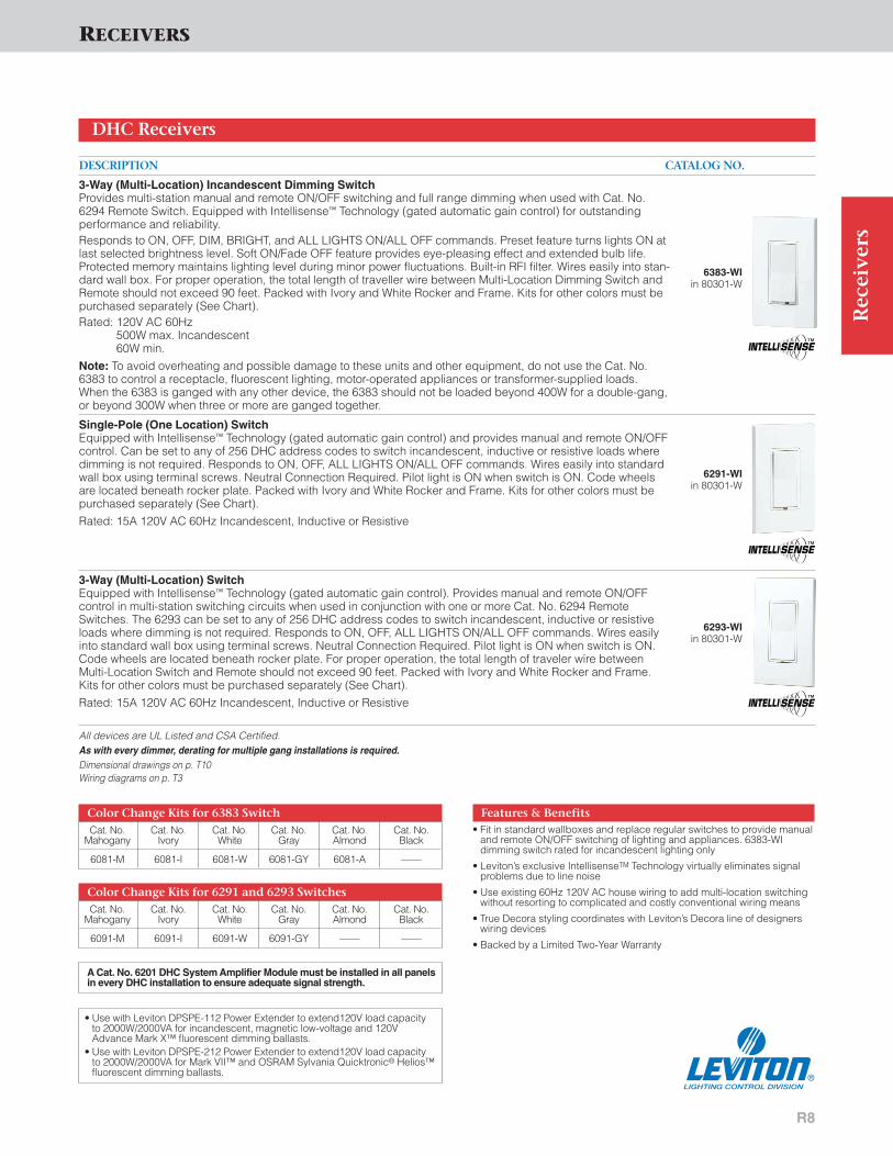
3-Way (Multi-Location) Incandescent Dimming SwitchProvides multi-station manual and remote ON/OFF switching and full range dimming when used with Cat. No.6294 Remote Switch. Equipped with Intellisense™ Technology (gated automatic gain control) for outstanding performance and reliability.Responds to ON, OFF, DIM, BRIGHT, and ALL LIGHTS ON/ALL OFF commands. Preset feature turns lights ON atlast selected brightness level. Soft ON/Fade OFF feature provides eye-pleasing effect and extended bulb life.Protected memory maintains lighting level during minor power fluctuations. Built-in RFI filter. Wires easily into stan-dard wall box. For proper operation, the total length of traveller wire between Multi-Location Dimming Switch andRemote should not exceed 90 feet. Packed with Ivory and White Rocker and Frame. Kits for other colors must bepurchased separately (See Chart).Rated: 120V AC 60Hz
500W max. Incandescent60W min.
Note: To avoid overheating and possible damage to these units and other equipment, do not use the Cat. No.6383 to control a receptacle, fluorescent lighting, motor-operated appliances or transformer-supplied loads.When the 6383 is ganged with any other device, the 6383 should not be loaded beyond 400W for a double-gang,or beyond 300W when three or more are ganged together.
Single-Pole (One Location) SwitchEquipped with Intellisense™ Technology (gated automatic gain control) and provides manual and remote ON/OFFcontrol. Can be set to any of 256 DHC address codes to switch incandescent, inductive or resistive loads wheredimming is not required. Responds to ON, OFF, ALL LIGHTS ON/ALL OFF commands. Wires easily into standardwall box using terminal screws. Neutral Connection Required. Pilot light is ON when switch is ON. Code wheelsare located beneath rocker plate. Packed with Ivory and White Rocker and Frame. Kits for other colors must bepurchased separately (See Chart).
Rated: 15A 120V AC 60Hz Incandescent, Inductive or Resistive
3-Way (Multi-Location) SwitchEquipped with Intellisense™ Technology (gated automatic gain control). Provides manual and remote ON/OFFcontrol in multi-station switching circuits when used in conjunction with one or more Cat. No. 6294 RemoteSwitches. The 6293 can be set to any of 256 DHC address codes to switch incandescent, inductive or resistiveloads where dimming is not required. Responds to ON, OFF, ALL LIGHTS ON/ALL OFF commands. Wires easilyinto standard wall box using terminal screws. Neutral Connection Required. Pilot light is ON when switch is ON.Code wheels are located beneath rocker plate. For proper operation, the total length of traveler wire betweenMulti-Location Switch and Remote should not exceed 90 feet. Packed with Ivory and White Rocker and Frame.Kits for other colors must be purchased separately (See Chart).
Rated: 15A 120V AC 60Hz Incandescent, Inductive or Resistive
All devices are UL Listed and CSA Certified.As with every dimmer, derating for multiple gang installations is required.Dimensional drawings on p. T10Wiring diagrams on p. T3
DHC Receivers
Color Change Kits for 6291 and 6293 SwitchesCat. No. Cat. No. Cat. No. Cat. No. Cat. No. Cat. No.
Mahogany Ivory White Gray Almond Black
6091-M 6091-I 6091-W 6091-GY — —
Color Change Kits for 6383 SwitchCat. No. Cat. No. Cat. No. Cat. No. Cat. No. Cat. No.
Mahogany Ivory White Gray Almond Black
6081-M 6081-I 6081-W 6081-GY 6081-A —
6291-WIin 80301-W
6293-WIin 80301-W
6383-WIin 80301-W
Features & Benefits• Fit in standard wallboxes and replace regular switches to provide manual
and remote ON/OFF switching of lighting and appliances. 6383-WI dimming switch rated for incandescent lighting only
• Leviton’s exclusive IntellisenseTM Technology virtually eliminates signalproblems due to line noise
• Use existing 60Hz 120V AC house wiring to add multi-location switchingwithout resorting to complicated and costly conventional wiring means
• True Decora styling coordinates with Leviton’s Decora line of designerswiring devices
• Backed by a Limited Two-Year Warranty
A Cat. No. 6201 DHC System Amplifier Module must be installed in all panelsin every DHC installation to ensure adequate signal strength.
• Use with Leviton DPSPE-112 Power Extender to extend120V load capacity to 2000W/2000VA for incandescent, magnetic low-voltage and 120VAdvance Mark X™ fluorescent dimming ballasts.
• Use with Leviton DPSPE-212 Power Extender to extend120V load capacity to 2000W/2000VA for Mark VII™ and OSRAM Sylvania Quicktronic® Helios™ fluorescent dimming ballasts.

R9
Rec
eive
rsRECEIVERS
DESCRIPTION CATALOG NO.
3-Way and 4-Way (Multi-Location) Remote SwitchFor use with DHC Cat. Nos. 6383 and 6293 Multi-Location Switches as a remote switch. The 6294 provides 3-Way, 4-Way and higher-level control in conjunction with these units. It cannot be used for any other purpose in theDHC network. The unit wires easily into standard wall box using terminal screws. For proper operation, the totallength of traveler wire between Multi-Location Switch and Remote should not exceed 90 feet Available inMahogany (no dash), Ivory (-I), White (-W), Almond (-A) and Gray (-GY). Specify color(s) when ordering, as snap-on cover and frame kits cannot be used with the 6294.No Load Rating—For use with 6383 and 6293 Units Only
Double Pole Wall SwitchEquipped with Intellisense™ Technology (gated automatic gain control). Provides local and remote ON/OFF con-trol. Responds to ON/OFF and ALL OFF commands from controllers. Can be set to any of the 256 DHC addresscodes. Intended for control of pool pumps, air conditioning units, spa heaters and pumps, and other large resi-dential loads. Wire easily into any standard wall box by means of six-inch leads. Available in Ivory only.Rated: 20A 2 HP 250V AC 60Hz
Dimensional drawings on p. T10Wiring diagrams on p. T3
DHC Receivers
6294-Win 80301-W
6371-I in 80301-I
Features & Benefits• Remote Units add multi-location capability to dimmer and switch
receivers
• Fit in standard wallboxes to replace regular switches
• Leviton’s exclusive Intellisense™ Technology virtually eliminates com-mand signal problems due to line noise
• 6371-I Heavy-duty appliance switch available for automated control ofheavy-duty loads such as air conditioning and pool pumps
• True Decora styling coordinates with Leviton’s Decora line of wiringdevices
• Backed by a Limited Two-Year Warranty

R10
RECEIVERS
Rec
eive
rs
DESCRIPTION CATALOG NO.
Universal Low Voltage ModuleAlmost any device operated at low voltages can now be automated using the 6337. This receiver interfacesbetween the low voltage device and the 120V AC wiring network. It receives an ON or OFF command from DHCTransmitters and can operate sprinkler systems, designated lighting, skylight closures, heating systems, garage door openers and other lighting and motor loads. Simply connect LV wiring tothe screw terminal on the module and plug it into any 120V wall outlet.In addition to switching contacts, the 6337 has a built-in alarm that can be set to sound whenever the switch contacts are closed. The 6337 can be set to operate the relay only, the alarm only, or both the relay and the alarm.The 6337 can also be set for momentary operation so that the relay and/or the alarm will be turned on for approximately two seconds in response to any ON command. Does not respond to ALL LIGHTS ON orDIM/BRIGHT commands.Rated: 120V 60Hz AC only.Contacts: 5A 12V DC,
100VA 30V DC Inductive
Dimensional drawings on p. T10
DHC Receivers
6337
Features & Benefits• Universal Low Voltage Module can automate devices operated at low volt-
ages such as sprinklers, skylights, and heating/AC systems
• Backed by a Limited Two-Year Warranty
A Cat. No. 6201 DHC System Amplifier Module must be installed in all panelsin every DHC installation to ensure adequate signal strength.

R11
RECEIVERSR
ecei
vers
DESCRIPTION CATALOG NO.
Split Duplex Wall ReceptacleEquipped with Intellisense (gated automatic gain control). Top outlet provides ON/OFF control in response to con-troller command signals. Bottom outlet is continuously live. Local control of any light of appliance plugged into thecontrolled outlet can be achieved by switching the load ON/OFF switch once or twice. Will not respond to ALLLIGHTS ON command. Fits standard wall boxes and supplied with leads for easy installation. Available in Ivory (-I), White (-W), Almond (A).Rated: 15A 120V 60Hz AC only. NEMA 5-15R
Duplex Wall ReceptacleEquipped with Intellisense (gated automatic gain control). Same as 6227, but with both top and bottom outletsproviding ON/OFF control in response to controller command signals. Feed-through load lead allows control ofreceptacles downstream. Will not respond to ALL LIGHTS ON command. No local control available. Available in Ivory (-I), White (-W).Rated: 15A 120V 60Hz AC only. NEMA 5-15R
Single Wall ReceptacleEquipped with Intellisense (gated automatic gain control). Provides ON/OFF control. No local control available.Wires easily into standard wallbox using supplied six-inch leads. Will not respond to ALL LIGHTS ON command.Available in Ivory (-I), White (-W).Rated: 20A 120V 60Hz AC only. NEMA 5-20R
Single Wall ReceptacleEquipped with Intellisense (gated automatic gain control). Provides ON/OFF control. No local control available.Wires easily into standard wallbox using supplied six-inch leads. Will not respond to ALL LIGHTS ON command.Available in Ivory (-I), White (-W).Rated: 20A 250V 60Hz AC only. NEMA 6-20R
Note: Receptacle modules will not respond to ALL ON commandAll devices are UL Listed. Also CSA Certified except where indicated by HDimensional drawings on p. T11Wiring diagrams on p. T3
DHC Receivers
6296-I, 6296-W,
6298-I, 6298-W,
6280-I, 6280-W,
6227-I,6227-W,6227-A
Features & Benefits• Configurations for all commonly used amperage/voltage house
combinations
• Fit in standard wallboxes to provide remote switching
• Leviton’s exclusive IIntellisense™ Technology virtually eliminates switchingproblems due to line noise
• True Decora styling coordinates with Leviton’s Decora line of wiring devices
• Backed by a Limited Two-Year Warranty
NEMA 5-15RG
W
NEMA 5-15RG
W
NEMA 5-20RG
W
NEMA 6-20RG
A Cat. No. 6201 DHC System Amplifier Module must be installed in all panelsin every DHC installation to ensure adequate signal strength.

DESCRIPTION CATALOG NO.
Fixture Relay ModuleCan be mounted at either an incandescent or fluorescent fixture by means of adhesive strips. Responds toON/OFF and ALL LIGHTS ON/ALL OFF commands from controllers. Equipped with leads for easy installation.
Rated: 15A 120V 60Hz AC only, incandescent, inductive (1/2 HP), or resistive.
Dimming Fixture ModuleCan be mounted at an incandescent fixture by means of adhesive strips. Responds to ON/OFF, DIM/BRIGHTENand ALL LIGHTS ON/ALL OFF commands from controllers. Equipped with leads for easy installation.
Rated: 300W incandescent 120V 60Hz AC only.
All devices are UL Listed and CSA Certified.Dimensional drawings on p. T11Wiring diagrams on p. T4
DHC Receivers Modules
Features & Benefits• Fixture modules provide direct control for fixtures where only remote
control is necessary• Backed by a Limited Two-Year Warranty
6375
6376
Rec
eive
rs
R12
RECEIVERS


DHC CONTROLLERS
Leviton DHC Controllers provide flexible controloptions for a DHC customized home automation net-work. Controllers are available as wall-mount andtable-top programmers (including a version withScene Lighting Macro capability), wireless hand-heldunits, outdoor motion sensor and photocell units;telephone transponders, multi-keypad wall switches,burglar alarm interface and dry-contact modules.
DHC Controllers are easy to install—most modules aremounted in standard wallboxes while others are simplyplugged into any AC receptacle.
Depending on the type of DHC Controller, the devicesends DHC Command Signals to receiver modulesthat turn lights and appliances ON or OFF, DIM orBRIGHTEN lighting, select Lighting Scene Macros, or turn ALL LIGHTS ON or OFF. Up to four DHCcontrollers can be wired into a single branch circuit.
C1
Co
ntr
oll
ers
NEW FROM LEVITON
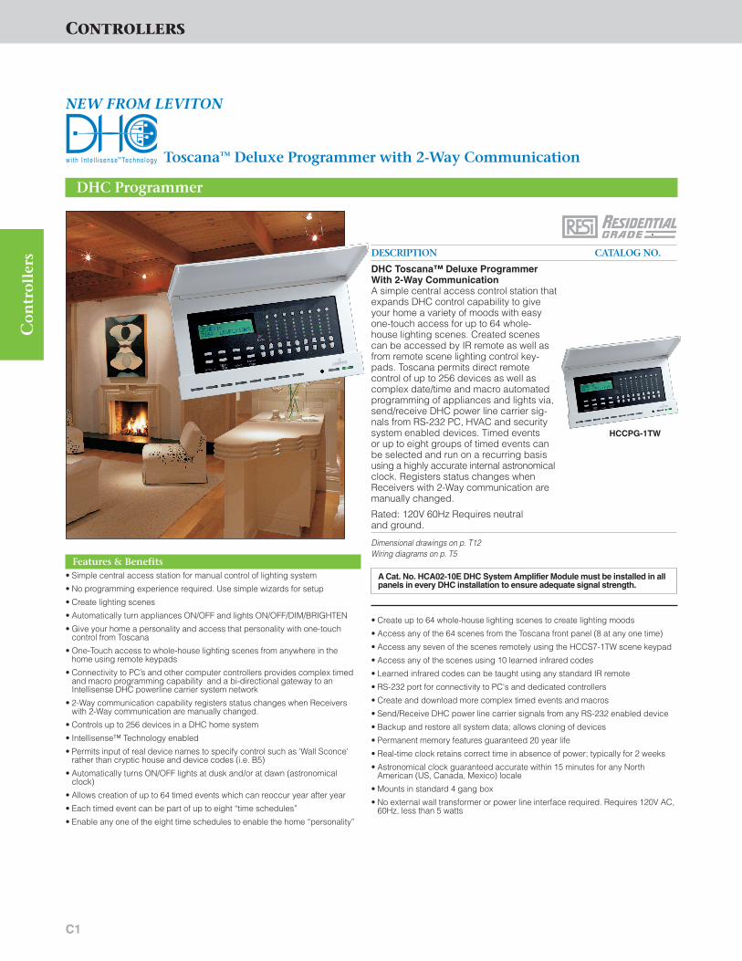
Toscana™ Deluxe Programmer with 2-Way Communication
DESCRIPTION CATALOG NO.
DHC Toscana™ Deluxe ProgrammerWith 2-Way CommunicationA simple central access control station thatexpands DHC control capability to giveyour home a variety of moods with easyone-touch access for up to 64 whole-house lighting scenes. Created scenescan be accessed by IR remote as well asfrom remote scene lighting control key-pads. Toscana permits direct remote control of up to 256 devices as well ascomplex date/time and macro automatedprogramming of appliances and lights via,send/receive DHC power line carrier sig-nals from RS-232 PC, HVAC and securitysystem enabled devices. Timed events or up to eight groups of timed events canbe selected and run on a recurring basisusing a highly accurate internal astronomicalclock. Registers status changes whenReceivers with 2-Way communication aremanually changed.
Rated: 120V 60Hz Requires neutral and ground.
Dimensional drawings on p. T12Wiring diagrams on p. T5
DHC Programmer
Features & Benefits• Simple central access station for manual control of lighting system
• No programming experience required. Use simple wizards for setup
• Create lighting scenes
• Automatically turn appliances ON/OFF and lights ON/OFF/DIM/BRIGHTEN
• Give your home a personality and access that personality with one-touch control from Toscana
• One-Touch access to whole-house lighting scenes from anywhere in thehome using remote keypads
• Connectivity to PC’s and other computer controllers provides complex timedand macro programming capability and a bi-directional gateway to anIntellisense DHC powerline carrier system network
• 2-Way communication capability registers status changes when Receiverswith 2-Way communication are manually changed.
• Controls up to 256 devices in a DHC home system
• Intellisense™ Technology enabled
• Permits input of real device names to specify control such as 'Wall Sconce'rather than cryptic house and device codes (i.e. B5)
• Automatically turns ON/OFF lights at dusk and/or at dawn (astronomicalclock)
• Allows creation of up to 64 timed events which can reoccur year after year
• Each timed event can be part of up to eight “time schedules”
• Enable any one of the eight time schedules to enable the home “personality”
HCCPG-1TW
A Cat. No. HCA02-10E DHC System Amplifier Module must be installed in allpanels in every DHC installation to ensure adequate signal strength.
CONTROLLERS
• Create up to 64 whole-house lighting scenes to create lighting moods
• Access any of the 64 scenes from the Toscana front panel (8 at any one time)
• Access any seven of the scenes remotely using the HCCS7-1TW scene keypad
• Access any of the scenes using 10 learned infrared codes
• Learned infrared codes can be taught using any standard IR remote
• RS-232 port for connectivity to PC's and dedicated controllers
• Create and download more complex timed events and macros
• Send/Receive DHC power line carrier signals from any RS-232 enabled device
• Backup and restore all system data; allows cloning of devices
• Permanent memory features guaranteed 20 year life
• Real-time clock retains correct time in absence of power; typically for 2 weeks
• Astronomical clock guaranteed accurate within 15 minutes for any NorthAmerican (US, Canada, Mexico) locale
• Mounts in standard 4 gang box
• No external wall transformer or power line interface required. Requires 120V AC,60Hz, less than 5 watts

C2
CONTROLLERS
NEW FROM LEVITON
with Updated Decora Rocker Styling and 2-Way Communication
DESCRIPTION CATALOG NO.
One-Address ON/OFF Wall Mounted SwitchController with 2-Way CommunicationOne ON/OFF rocker transmits ON/OFF commands toone address. Illuminated green LED at bottom offace indicates unit is On. (Note: Shipped in Whiteonly. Order color change kits for Ivory and Almond)
Rated: 120V 60Hz AC Only
ALL LIGHTS ON/ALL OFF Wall Mounted SwitchController with 2-Way CommunicationOne ALL LIGHTS ON/ALL OFF rocker transmits com-mands to all receivers set to the same letter code asthis transmitter. Provides “Panic Button” lighting con-trol for safety and security. NOTE: ReceptacleReceivers will not respond to ALL ON command.Illuminated green LED at bottom of face indicatesunit is On. (Note: Shipped in White only. Order colorchange kits for Ivory and Almond)
Rated: 120V 60Hz AC Only
Dimensional drawings on p. T12Wiring diagrams on p. T5
DHC Controllers
Features & Benefits• Newly streamlined Decora designer styling enhances every interior and
adds a family look when ganged with other Decora devices
• Remote ALL LIGHTS ON/ALL LIGHTS OFF switching can be used inhome security applications to deter intruders or signal neighbors inemergencies (Cat. No. HCC1A-1TW only)
• 2-Way Communication permits status of Receivers changed locally tobe reflected and computer-based controllers can receive a controllerstatus update
• Fit in standard wallboxes and replace regular switches to provideremote ON/OFF switching, dimming and Scene Lighting Control
• Leviton’s exclusive Intellisense™ Technology virtually eliminates signalproblems due to line noise
• Use existing 60Hz 120V AC house wiring to add multi-location switchingwithout complicated and costly conventional wiring means
• Compatible with Decora screwless and Decora standard designerwallplates
• Green LED illuminates to confirm ON command sent
• Color change kits allow fast color changeovers. (Devices ship in Whiteonly) See chart for Color Change Kits (must be purchased separately)
• UL Listed and CSA Certified
• All devices are UL Listed (File #E-66800), CSA Certified (File #LR-54628) and UL 244A Tested (and others where appropriate)
• Backed by a Limited Two-Year Warranty
HCC10-1TWin 80301-W
Color Change Kits For HCC10-1TW, HCC1A-1TW Color Change Kit Cat. Nos.
Controller Cat. Nos.Cat. No. Ivory Cat. No.White Cat. No. Almond
HCC10-1TW, HCC1A-1TW DRK0S-0LI DRK0S-0LW DRK0S-0LA
HCC1A-1TWin 80301-W
Maximum of 4 Controllers should be installed on a single branch circuit
Co
ntr
oll
ers

C3
Co
ntr
oll
ers
CONTROLLERS
NEW FROM LEVITON
with Decora Rocker-Within-A-Rocker Design and 2-Way Communication
DESCRIPTION CATALOG NO.
One-Address Wall Mounted Rocker-Within-A-Rocker Dimming Controller with 2-Way CommunicationOne ON/OFF rocker transmits ON/OFF commands to one address in the same letter code group as thisswitch controller while the built-in arrow-shapedrocker transmits BRIGHT/DIM commands to thatsame address. Illuminated green LED at bottom offace indicates unit is On. (Note: Shipped in Whiteonly. Order color change kits for Ivory and Almond)
Rated: 120V 60Hz AC Only
Dimensional drawings on p. T12Wiring diagrams on p. T5
DHC Controllers
Features & Benefits• Features a unique design that combines a Decora ON/OFF preset
switch with an arrow-shaped rocker-within-a-rocker for selectingDIM/BRIGHT levels
• Fit in standard wallboxes and replace regular switches to provideremote ON/OFF switching, dimming and Scene Lighting Control
• 2-Way Communication permits status of Receivers changed locally tobe reflected and computer-based controllers can receive a controllerstatus update
• Leviton’s exclusive Intellisense™ Technology virtually eliminates signalproblems due to line noise
• Use existing 60Hz 120V AC house wiring to add multi-location switchingwithout complicated and costly conventional wiring means
• Compatible with Decora screwless and Decora standard designerwallplates
• Green LED illuminates to confirm ON command sent
• Decora-styled design enhances every interior and adds a family lookwhen ganged with other Decora devices
• Color change kits allow fast color changeovers. (Devices ship in Whiteonly) See chart for Color Change Kits (must be purchased separately)
• All devices are UL Listed (File #E-66800), CSA Certified (File #LR-54628) and UL 244A Tested (and others where appropriate)
• Backed by a Limited Two-Year Warranty
HCC1D-1TWin 80301-W
Color Change Kits For HCC1D-1TW Color Change Kit Cat. Nos.
Controller Cat. No.Cat. No. Ivory Cat. No.White Cat. No. Almond
HCC1D-1TW DRK1D-00I DRK1D-00W DRK1D-00A
Maximum of 4 Controllers should be installed on a single branch circuit

C4
Color Change Kits for HCC2D-1TW, HCC3D-1TW, HCC4D-1TW, HCC4A-1TW
CONTROLLERS
NEW FROM LEVITON
with Updated Decora Styling and 2-Way Communication
DESCRIPTION CATALOG NO.
Two-Address Wall Mounted Dimming SwitchController with 2-Way CommunicationTwo sets of ON/OFF buttons transmit ON/OFF com-mands to two sequential addresses† in the same lettercode group as this controller. Also, provides remotecontrol of ON/OFF-only receivers for fluorescent loadsand inductive loads of up to 10 Amps. One set ofGROUP BRIGHT/DIM buttons transmits GROUPBRIGHT/DIM commands to the most recently selectedaddress. (Note: Shipped in White only. Order colorchange kits for Ivory and Almond)Rated: 120V 60Hz AC Only
Three-Address Wall Mounted Dimming SwitchController with 2-Way CommunicationThree sets of ON/OFF buttons transmit ON/OFF com-mands to three sequential addresses† in the same let-ter code group as this controller. One set of GROUPBRIGHT/DIM buttons transmits GROUP BRIGHT/DIMcommands to the most recently selected address.(Note: Shipped in White only. Order color change kitsfor Ivory and Almond)Rated: 120V 60Hz AC Only
Four-Address Wall Mounted Dimming SwitchController with 2-Way CommunicationFour sets of ON/OFF buttons transmit ON/OFF com-mands to four sequential addresses† in the same lettercode group as this controller. One set of GROUPBRIGHT/GROUP DIM buttons transmits GROUPBRIGHT/DIM commands to the most recently selectedaddress. (Note: Shipped in White only. Order colorchange kits for Ivory and Almond)Rated: 120V 60Hz AC Only
Three-Address Wall Mounted Dimming All LIGHTS ON/ALL OFF Switch Controller with 2-Way CommunicationThree sets of ON/OFF buttons transmit ON/OFF com-mands to three sequential addresses† in the same let-ter code group as this controller. One set of GROUPBRIGHT/DIM buttons transmits GROUP BRIGHT/DIMcommands to the most recently selected address. Oneset of ALL LIGHTS ON/ALL OFF buttons transmits com-mands to all receivers set to the same letter code asthis controller. (Note: Shipped in White only. Order colorchange kits for Ivory and Almond)Rated: 120V 60Hz AC Only†For remote control of non-sequentially addressed Receiver(s) applications, please see Cat. No.HCCS7 Scene Controller Dimensional drawings on p. T15 Wiring diagrams on p. T5
DHC Controllers
Features & Benefits• Remote ALL ON/ALL OFF switching keypad can be used in home
security applications to deter intruders or signal neighbors in emergen-cies (Cat. No. HCC4A-1TW only)
• Fit in standard wallboxes and replace regular switches to provideremote ON/OFF switching, dimming and Scene Lighting Control
• 2-Way Communication permits status of Receivers changed locally tobe reflected and computer-based controllers can receive a controllerstatus update
• Leviton’s exclusive Intellisense™ Technology virtually eliminates signalproblems due to line noise
• Use existing 60Hz 120V AC house wiring to add multi-location switchingwithout complicated and costly conventional wiring means
• Compatible with Decora screwless and Decora standard designerwallplates
• Green LED illuminates to confirm ON command sent to left of last-activated set of ON/OFF buttons
• Newly streamlined Decora faceplate styling enhances any interior andadds a family look when ganged with other Decora devices
• Color change kits allow fast color changeovers. (Devices ship in White only) See chart for Color Change Kits (must be purchased separately)
• All devices are UL Listed (File #E-66800), CSA Certified (File #LR-54628) and UL 244A Tested (and others where appropriate)
• Backed by a Limited Two-Year Warranty
HCC2D-1TWin 80301-W
Color Change Kit Cat. Nos.Controller Cat. Nos.Cat. No. White Cat. No.Ivory Cat. No. Almond
HCC2D-1TW DCK2D-00W DCK2D-00I DCK2D-00A
HCC3D-1TW DCK3D-00W DCK3D-00I DCK3D-00A
HCC4D-1TW DCK4D-00W DCK4D-00I DCK4D-00A
HCC4A-1TW DCK4A-00W DCK4A-00I DCK4A-00A
HCC3D-1TWin 80301-W
HCC4D-1TWin 80301-W
HCC4A-1TWin 80301-W
Maximum of 4 Controllers should be installed on a single branch circuit
Co
ntr
oll
ers

C5
CONTROLLERS
NEW FROM LEVITON
with Updated Decora Styling and 2-Way Communication
DESCRIPTION CATALOG NO.
Seven-Scene Dimming Wall Switch Controller with 2-Way CommunicationEach of seven SCENE buttons transmits ON commands to preset levels to 12 sequentialaddresses in the same letter code group as thisController. (Note: 12-address sequence continues at address 1 if address 16 is reached before all 12sequential addresses are completed.) Only Cat. Nos.HCM06, HCM10, HCS10, 6343, 16383 or 16293Scene Capable Switch Receivers can be used withthis controller. One set of SCENE BRIGHT/DIM buttonstransmits SCENE BRIGHT/DIM commands to the mostrecently selected scene. One OFF button transmitsOFF command to the most recently selected scene. (Note: Shipped in White only. Order color change kitsfor Ivory and Almond)
Rated: 120V 60Hz AC Only
Dimensional drawings on p. T12Wiring diagrams on p. T5
DHC Controllers
Features & Benefits• Allows creation of seven lighting scenes quickly and easily using any
number of Scene Capable Receivers in conjunction with one or moreSeven-Scene Dimming Wall Switch Controllers.
• Fit in standard wallboxes and replace regular switches to provide remoteON/OFF switching, dimming and Scene Lighting Control
• 2-Way Communication permits status of Receivers changed locally tobe reflected and computer-based controllers can receive a controllerstatus update
• Leviton’s exclusive Intellisense™ Technology virtually eliminates signalproblems due to line noise
• Use existing 60Hz 120V AC house wiring to add multi-location switchingwithout complicated and costly conventional wiring means
• Compatible with Decora screwless and Decora standard designerwallplates
• Green LED illuminates to confirm ON command sent next to the mostrecently selected scene
• Streamlined Decora styling enhances any interior and adds a family lookwhen ganged with other Decora devices
• Color change kits allow fast color changeovers. (Devices ship in White only) See chart for Color Change Kits (must be purchased separately)
• All devices are UL Listed (File #E-66800), CSA Certified (File #LR-54628)and UL 244A Tested (and others where appropriate)
• Backed by a Limited Two-Year Warranty
HCCS7-1TWin 80301-W
Color Change Kits For HCCS7-1TW Color Change Kit Cat. Nos.
Controller Cat. No.Cat. No. White Cat. No. Ivory Cat. No. Almond
HCCS7-1TW DCKS7-00W DCKS7-00I DCKS7-00A
Maximum of 4 Controllers should be installed on a single branch circuit
Co
ntr
oll
ers
Programming HCCS7-1TW: Hold down desired scene button until flashingLED programming mode begins. Set all Scene Capable Switch Receivers to desired levels. Press the previously selected scene button again to end programming. To unprogram a scene from DHC devices, hold down thedesired scene button until flashing LED programming mode begins. Then hit the OFF button. A DHC dimmer can ignore a scene if its airgap switch is pulled during the programming cycle. Controller and receivers must be set to the same address.

C6
NOTE: 16400/16450 Controller Bodies and Faces are not interchangeablewith older-style DHC Controller Bodies and Faces.NOTE: No more than 4 transmitters should be installed on a single branch circuit.
CONTROLLERS
DESCRIPTION CATALOG NO.
Uni-Base Wall Mounted Controller Body with Scene Control CapabilityThe Cat. No. 16400 accepts any of the Cat. No. 16450 Controller Faces. Controller Faces feature LED to the left of each keypad to indicate last ON/OFF command signal sent to an address. Faces are provided with press-onlabels to identify fixture(s) controlled and a clear plastic cover to protect the face and labels. Back offset strap on 16400 Uni-Base body provides unit with a clean, flush-mounted appearance. The 16400 features Intellisense(gated automatic gain control) to transmit clear command signals without noise interference. Intellisense™
Technology enhances overall system performance and reliability. The 16400 command signals will not effect command signals sent simultaneously from other transmitters. Rated: 120V 60Hz AC Only. Power Consumption: 2 Watts
One-Button Controller FaceOne ON/OFF keypad transmits ON/OFF commands to one address. Available in Ivory (-1), Almond (-1AL) orWhite (-1W).
One-Button ALL LIGHTS ON/ALL OFF Controller FaceOne ALL LIGHTS ON/ALL OFF keypad transmits commands to all receivers set to the same letter code as thiscontroller. Provides “Panic Button” lighting control for safety and security. NOTE: Receptacle Receivers will notrespond to ALL ON command. Available in Ivory (-1A), Almond (-1AA) or White (-1AW).
Two-Button Controller FaceTwo ON/OFF keypads transmit ON/OFF commands for two sequential addresses set to the same letter code asthis controller. Available in Ivory (-2), Almond (-2AL) or White (-2W).
Two-Button Dimming Controller FaceOne-ON/OFF keypad transmits ON/OFF commands and one keypad transmits DIM and BRIGHT commands forone address in the same Letter Code group as this controller. Available in Ivory (-2D), Almond (-2DA) or White (-2DW).
Four-Button Controller FaceFour ON/OFF keypads transmit ON/OFF commands for (4) sequential addresses set to the same letter code asthis controller. Available in Ivory (-4), Almond (-4AL) or White (-4W).
Four-Button ALL LIGHTS ON/ALL OFF Controller FaceThree ON/OFF keypads transmit ON/OFF commands for three sequential addresses set to the same letter codeas this controller, and one keypad transmits ALL LIGHTS ON/ALL OFF to all receivers set to the same Letter Codeas this controller (except receptacle receivers. Available in Ivory (-4A), Almond (-4AA) or White (-4AW).
Four-Button Dimming Controller FaceThree ON/OFF keypads transmit ON/OFF commands to three sequential addresses in the same letter code groupas this controller and one keypad transmits DIM and BRIGHT commands for the same three addresses. Availablein Ivory (-2D), Almond (-4DA) or White (-4DW).
Four-Button Scene Lighting Control Face*Four Scene Control keypads transmit ON/OFF commands to execute four separate programmed lighting scenesfor multiple Cat. Nos. 6343 and 16383 Dimmer Switch Receivers and Cat. No. 16293 Switch Receiver with SceneCapability. Available in Ivory (-S), Almond (-SA) or White (-SW).
Four-Button Scene Lighting Control Face with ALL DIM/ALL BRIGHT*Three Scene Control keypads transmit ON/OFF commands to execute three separate programmed lightingscenes for multiple Cat. Nos. 6343 and 16383 Dimmer Switch Receivers and Cat. No. 16293 Switch Receiver withScene Capability. One Keypad transmits ALL DIM/ALL BRIGHT commands to all programmed 6343 and 16383Receivers. Available in Ivory (-SD), Almond (-SDA) or White (-SDW).*The 16450-S and 16450-SD utilize extended code format. This command structure is not compatible with older versions of the DHC System Coupler/Repeater Cat. No. 6201.All devices are UL Listed only, not CSA Certified.Dimensional drawings on p. T12 Wiring diagrams on p. T5
DHC Controllers
16450-1
16450-1A(Shown)
16450-2
16450-2D(Shown)
16450-4
16450-4A
16450-4D(Shown)
16450-S
16450-SD
16400
Features & Benefits• Simply change 16450 Controller Face on 16400 Uni-Base Controller Body to
change functions. Controller Face LED’s indicate last keypad to send signal;pre-printed press-on labels to identify controlled fixtures.
• Operates over existing 120V AC 60Hz wiring• Decora-styled to coordinate with Leviton’s Decora line of wiring devices• Backed by a Limited Two-Year Warranty
Sample Labels for 16450 Controller FacesON OFF UPSTAIRS SPOTS EASTON OFF DOWNSTAIRS GARDEN WESTON OFF ENTRY WALKWAY COVEON OFF FOYER DRIVEWAY PLAYROOMALL ON OFF HALL SECURITY CHANDELIERBRIGHT DIM STAIRWAY FRONT AQUARIUMINSIDE LIVING ROOM BACK NURSERYOUTSIDE DINING ROOM STEPS SPALEFT DISPLAY GARAGE LAMPRIGHT KITCHEN POOL LOW VOLTAGESCONCES COUNTER FILTER FLUORESCENTOVERHEAD BEDROOM GREENHOUSE GYMWALL CLOSET TENNIS SAUNARECESSED BATHROOM NORTH ATTICTRACK BASEMENT SOUTH OFFICE
Co
ntr
oll
ers
Programming 16450-S and 16450-SD Scene Controllers: Press program button on 16450 keypad unit until flashing LED programmingmode begins. Set all Scene Capable Switch Receivers to desired levels. Press the left side of the ON/OFF Scene Control rocker switch thatyou wish to program. Press program button on 16450 keypad again to finish. Transmitter and receivers must be set to the same address
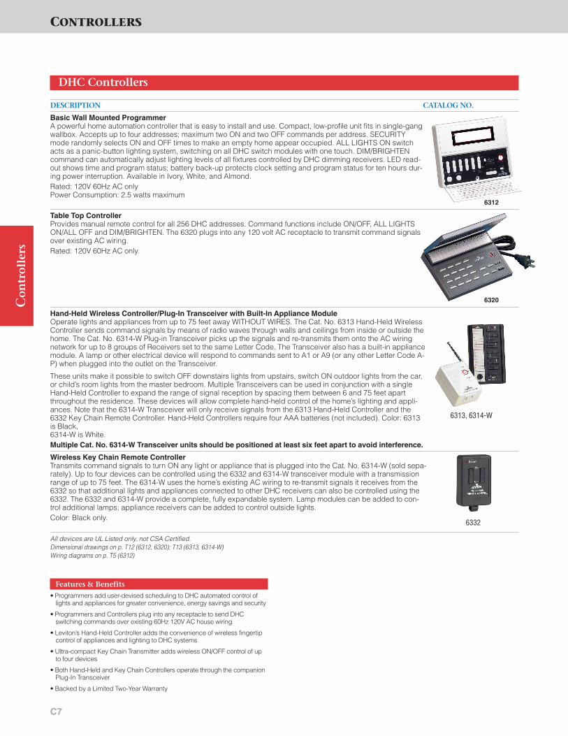
C7
Co
ntr
oll
ers
CONTROLLERS
DESCRIPTION CATALOG NO.
Basic Wall Mounted ProgrammerA powerful home automation controller that is easy to install and use. Compact, low-profile unit fits in single-gangwallbox. Accepts up to four addresses; maximum two ON and two OFF commands per address. SECURITYmode randomly selects ON and OFF times to make an empty home appear occupied. ALL LIGHTS ON switchacts as a panic-button lighting system, switching on all DHC switch modules with one touch. DIM/BRIGHTENcommand can automatically adjust lighting levels of all fixtures controlled by DHC dimming receivers. LED read-out shows time and program status; battery back-up protects clock setting and program status for ten hours dur-ing power interruption. Available in Ivory, White, and Almond.Rated: 120V 60Hz AC onlyPower Consumption: 2.5 watts maximum
Table Top ControllerProvides manual remote control for all 256 DHC addresses. Command functions include ON/OFF, ALL LIGHTSON/ALL OFF and DIM/BRIGHTEN. The 6320 plugs into any 120 volt AC receptacle to transmit command signalsover existing AC wiring.Rated: 120V 60Hz AC only.
Hand-Held Wireless Controller/Plug-In Transceiver with Built-In Appliance ModuleOperate lights and appliances from up to 75 feet away WITHOUT WIRES. The Cat. No. 6313 Hand-Held WirelessController sends command signals by means of radio waves through walls and ceilings from inside or outside thehome. The Cat. No. 6314-W Plug-in Transceiver picks up the signals and re-transmits them onto the AC wiringnetwork for up to 8 groups of Receivers set to the same Letter Code. The Transceiver also has a built-in appliancemodule. A lamp or other electrical device will respond to commands sent to A1 or A9 (or any other Letter Code A-P) when plugged into the outlet on the Transceiver.
These units make it possible to switch OFF downstairs lights from upstairs, switch ON outdoor lights from the car,or child’s room lights from the master bedroom. Multiple Transceivers can be used in conjunction with a singleHand-Held Controller to expand the range of signal reception by spacing them between 6 and 75 feet apartthroughout the residence. These devices will allow complete hand-held control of the home’s lighting and appli-ances. Note that the 6314-W Transceiver will only receive signals from the 6313 Hand-Held Controller and the6332 Key Chain Remote Controller. Hand-Held Controllers require four AAA batteries (not included). Color: 6313is Black, 6314-W is White. Multiple Cat. No. 6314-W Transceiver units should be positioned at least six feet apart to avoid interference.
Wireless Key Chain Remote ControllerTransmits command signals to turn ON any light or appliance that is plugged into the Cat. No. 6314-W (sold sepa-rately). Up to four devices can be controlled using the 6332 and 6314-W transceiver module with a transmissionrange of up to 75 feet. The 6314-W uses the home’s existing AC wiring to re-transmit signals it receives from the6332 so that additional lights and appliances connected to other DHC receivers can also be controlled using the6332. The 6332 and 6314-W provide a complete, fully expandable system. Lamp modules can be added to con-trol additional lamps; appliance receivers can be added to control outside lights.Color: Black only.
All devices are UL Listed only, not CSA Certified.Dimensional drawings on p. T12 (6312, 6320); T13 (6313, 6314-W)Wiring diagrams on p. T5 (6312)
DHC Controllers
Features & Benefits
• Programmers add user-devised scheduling to DHC automated control oflights and appliances for greater convenience, energy savings and security
• Programmers and Controllers plug into any receptacle to send DHC switching commands over existing 60Hz 120V AC house wiring
• Leviton’s Hand-Held Controller adds the convenience of wireless fingertipcontrol of appliances and lighting to DHC systems
• Ultra-compact Key Chain Transmitter adds wireless ON/OFF control of upto four devices
• Both Hand-Held and Key Chain Controllers operate through the companionPlug-In Transceiver
• Backed by a Limited Two-Year Warranty
6312
6320
6313, 6314-W
6332

C8
CONTROLLERS
Co
ntr
oll
ers
6308
DESCRIPTION CATALOG NO.
Passive Infrared ControllerA motion-sensing light control ideal for use in outdoor locations, such as backyards, garages and storage build-ings. Built-in infrared sensing technology monitors 4,000-sq. ft. field, 110 degrees wide, up to 40 feet in front ofunit. When the 6417 senses motion in its field of view, it can respond by sending two types of signals: ON com-mands to Receivers set to control lights at four sequential system addresses, and MOTION DETECTED signals toother 6417’s set to the same address. As long as the source of infrared radiation remains in the 6417 sensor field, it continues to send ON signals every six seconds to these addresses, providing the convenience of continuous illumination along a path from a garage to an entranceway, or around an entire residence, if desired. It can also turn on an inside lighting fixture as well as outdoor fixtures to help deter intruders. The 6417 is encased in a moisture-resistant housing. The control panel includes sensitivity adjustments to preventnuisance tripping by small animals and a time delay to set the length of time the lights stay on (6 seconds to 30minutes). Manual override of the 6417 controller can be achieved with the use of 16400/16450,6320, 26311 or6312 Controllers. Passive Infrared Transmitter installs easily into standard round outdoor junction box and comes complete withmounting plate, control unit, par lampholders and complete installation and operating instructions. Color: Brown
Photocell ControllerAutomatically senses approaching darkness and responds by sending ON commands to as many as four groupsof DHC Receivers (all receiver modules in each group must be set to the same Letter Code). The ReceiverModules respond by turning lights ON inside or outside the home. The 6308 will also transmit OFF commands inresponse to a user-selected number of hours that it’s been ON, or in response to approaching daylight. TheReceivers respond by turning their assigned lighting loads inside or outside the home OFF. The 6308 mounts on astandard round or GEM electrical box. Color: Brown
All devices are UL Listed only, not CSA Certified.Dimensional drawings on p. T13 (6308)Wiring diagrams on p. T6 (6308)
DHC Controllers
Features & Benefits
• DHC Passive Infrared Sensor/Transmitters can work alone or in multiplearrays to turn on designated lighting inside and outside the home whenmotion is detected for improved security and safety
• Up to four transmitters can be wired into a single branch circuit
• Photocell Sensor/Transmitters can add “night watchman” automatedswitching capability to any DHC network
• Backed by a Limited Two-Year Warranty
6417
MINMAX
RANGE
DARKLIGHT
DUSK
HOUSE CODE START CODE
13
5
79
11
13
15A
C
E
GI
K
M
O
TIME DELAY
300.1
0.22 5
15
MINUTES
+1
+2
+3
+4
SENSORIN OUT
Set range to prevent nuisance triggering
Adjust dusk controlto ambient light conditions
Program specificlights to be controlled - Sendscoded signals
Set time-off delayfrom between6 seconds and 30 minutes
Control Panel(bottom of sensor)
Controls up to4 groups of lightsto operate with duskor sensor controls
Control Panel for Outdoor Motion Sensor Cat. No. 6417

C9
DESCRIPTION CATALOG NO.
Telephone TransponderAllows user to control all 256 addresses in an entire DHC network from anywhere in the world using a Touch-Tone™ telephone. The DHC Transponder also functions as a DHC isolated contact (class B) module that can becontrolled from the phone or any DHC Transmitter. The 6325 includes a pair of low-voltage wire screw terminals.The Transponder simply plugs into any 120 volt AC receptacle and attaches to a phone jack using the line splitterprovided. The Transponder activates upon “hearing” its unique, user-devised access code. Users can order the6325 to send ON, OFF, ALL LIGHTS ON and ALL OFF commands using the phone keypad. For optimum perfor-mance, it is recommended that the 6325 be used on a dedicated phone line. The Transponder confirms all com-mands with a simulated human voice. The device is equipped with a 6-hour battery back up. Color: BlackNote: The Telephone Transponder does not work with proprietary telephone company answering modes or withcall waiting. It is advised to put Cat. No. 6325 on a dedicated telephone line.
Burglar Alarm InterfaceSimply plugs into a grounding 15 Amp receptacle. Connects to an existing intrusion alarm and turns lights ONwhenever the alarm is tripped. Provides choice of 3 modes of light switching when activated. Either a low-voltageinput (6-18V AC, DC or audio) or a dry contact closure can trigger the 6330. The unit has a test button that per-mits activation whether or not the device is connected to an alarm system. The ALL OFF button turns OFF any-thing that was turned ON by the unit.Available color: Ivory
Dry Contact Controller�Allow monitoring of up to four dry contact closures. No. 6315 Maintained Contact Controller sends ON or OFFcommand signals in response to contact opening or closure. No. 6316 Momentary Contact Controller sends ONor OFF command signals in response to contact closure, and no command signal upon contact openings. Theseunits can be used with photocells, infrared sensors, security system, motion sensors, thermostats and any otherdry-contact-based sensors. Installs in a single-gang wallbox. Color: IvoryPower to control side: 125V 60Hz AC Only.
LV LEAD COLOR TRANSMITS TOBlue A1*Orange A2*Yellow A3*Brown A4*
*Or any four sequential address codes within the same Letter Code group as the Transmitter.
All devices are UL Listed. Also CSA Certified except where indicated by �Dimensional drawings on p. T13Wiring diagrams on p. T6 (6315,6316)
DHC Controllers
Co
ntr
oll
ers
6330
6325
6315, 6316
Features & Benefits
• Telephone Transponder allows user to control an entire DHC network fromanywhere in the world using a touch-tone telephone
• Burglar Alarm Interface connects to existing intrusion alarms, issuing flash-ing light commands to DHC switching modules when tripped for improvedsecurity
• Up to four transmitters can be wired into a single branch circuit
• Dry Contact Transmitters link signaling from photocells, infrared sensors,security systems, motion sensors, and other dry contact transmitters toDHC controlled devices
• Backed by a Limited Two-Year Warranty
CONTROLLERS
Leviton highly recommends installing Network IntegrityProducts in every DHC application.
The Cat. No. HCA02-10E System Amplifier ensures thatthe DHC command signal travels throughout the home’sAC wiring. This versatile DHC component repeats thecommand signal and also makes sure that it is transmittedonto every phase in a residential wiring configuration.The System Amplifier also features Leviton’s exclusiveIntellisense™Technology to ensure reliable performanceeven when there's noise present on the AC powerline. AnHCA02-10E must be installed in all panels in every DHCinstallation to ensure adequate signal strength.
The Cat. No. 51120 Panel-Mounted Surge ProtectiveDevices provide AC powerline protection from high-energy, transient voltage surges that can damage allmicroprocessor-based electronic equipment, includingLeviton DHC components.
DHC NETWORK INTEGRITY PRODUCTS

N1
DESCRIPTION CATALOG NO.
DHC System Amplifier with Built-In Test Signal GeneratorPerforms a variety of functions to ensure outstanding DHC system performance and reliability. The module couples transmitter (programmer and controller) signals generated on the 120V leg where the transmitter drawspower onto the other leg in a 120/240V residential wiring system. The module also amplifies and repeats com-mand signals to maintain proper signal strength throughout the DHC system. Leviton’s exclusive Intellisense™Technology (gated automatic gain control) feature helps ensure top performance even when noise is present onthe AC powerline. The module provides convenient ON/OFF test signal transmission capability. This allows foreasy signal strength verification at individual module locations with Leviton’s Cat. No. 6386 Signal StrengthIndicator. The error lamp indicates that the Intellisense feature is activated. This product can not be used in 3-Phase systems
System Amplifier*Takes DHC programmer and controller signals generated on the 120V line phase from which the transmitterdraws power. Then couples the command signals at the zero crossing on the other line phase of a 120/240V sys-tem or any phase of a three-phase 120/208V residential wiring network. The 6201 should be installed at the mainpanel with its own dedicated 15 amp breaker, in accordance with NEC requirements. The unit is equipped withIntellisense (gated automatic gain control) for outstanding performance and reliability. Pilot light indicates whenDHC signal is transmitting. More than one 6201 may be used per household. Color: Black
*Cat. No. 6201 not compatible with HCCS7-1TW Scene Lighting controller
Dimensional drawings on p. T14Wiring diagrams on p. T7
DHC Network Integrity Products
Features & Benefits
• System Amplifier recommended for all DHC installations to ensure adequate command signal strength
• Panel-Mounted Surge Protective Device recommended for all DHC installations to protect DHC circuitry from damaging high-energy transientvoltage surges
• Cat. Nos. HCA02-10E and 6201 Backed by a Limited Two-Year Warranty,51120 Backed by a Limited 10-Year Warranty
NETWORK INTEGRITY PRODUCTSN
etw
ork
In
teg
rity
Pro
du
cts
An HCA02-10E must be installed in all panels in every HCCXX series DHC installation to ensure adequatesignal strength.
NOTE: A System Amplifier Module must be installed in all panels in every DHC installation to ensure adequatesignal strength.
6201
HCA02-10E
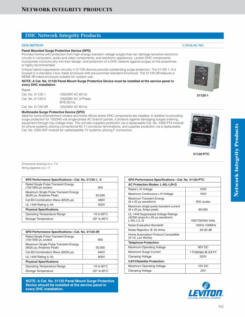
N2
Net
wo
rk I
nte
gri
ty P
rod
uct
s
NETWORK INTEGRITY PRODUCTS
DESCRIPTION CATALOG NO.
Panel Mounted Surge Protective Device (SPD)Provides homes with protection from high-energy transient voltage surges that can damage sensitive electronic circuits in computers, audio and video components, and electronic appliances. Leviton DHC components incorporate microcircuitry into their design, and protection of a DHC network against surges on the powerlines is highly recommended.Unique hybrid suppression circuitry in 51120 devices provide outstanding surge protection. The 51120-1,-3 ishoused in a standard J-box metal enclosure with pre-punched standard knockouts. The 51120-3R features aNEMA 3R-rated enclosure suitable for outdoor use.NOTE: A Cat. No. 51120 Panel Mount Surge Protective Device must be installed at the service panel in every DHC installation
Rated: Cat. No. 51120-1 120/240V AC 60 HzCat. No. 51120-3 120/208V AC 3-Phase
WYE 60 Hz Cat. No. 51120-3R 120/240V AC 60 Hz
Multimedia Surge Protective Device (SPD)Ideal for home entertainment centers and home offices where DHC components are installed. In addition to providingsurge protection for 120/240 volt single-phase AC branch panels, it protects against damaging surges enteringequipment through low-voltage lines. The unit also supplies protection via a replaceable Cat. No. 5350-PT4 modulefor phone systems utilizing conventional RJ-11 connector terminations; and supplies protection via a replaceableCat. No. 5350-SAT module for cable/satellite TV systems utilizing F connectors.
Dimensional drawings on p. T14Wiring diagrams on p. T7
DHC Network Integrity Products
51120-1
SPD Performance Specifications—Cat. No. 51120-PTC
AC Protection Modes: L-N/L-L/N-G
Rated L-N Voltage 120V
Maximum Continuous L-N Voltage 150V
Maximum Transient Energy (8 x 20 µs waveform) 950 Joules
Maximum single-pulse transient current (8 x 20 µs, Amps peak) 80,000
UL 1449 Suppressed Voltage Ratings(@500 amps 8 x 20 µs waveform) L-N/L-L/L-G 500/700/500 Volts
Noise Evaluation Bandwith 100Hz-100MHz
Noise Rejection @ 50 ohms 20-30 dB
Home Automation Protocol Campatible(X-10, Lon Works)
Telephone Protection:
Maximum Operating Voltage 90V DC
Maximum Surge Current 1.9 kAmps @ 3.8 kV
Clamping Voltage 220V
CATV/Satellite Protection:
Maximum Operating Voltage 10V DC
Clamping Voltage 25V
SPD Performance Specifications—Cat. No. 51120-1, -3
Rated Single Pulse Transient Energy(10x1000 µs Joules) 950
Maximum Single Pulse Transient Energy(8x20 µs, Amperes Peak) 50,000
Cat B3 Combination Wave (8X20 µs) 480V
UL 1449 Rating (L-N) 500V
Physical Specifications
Operating Temperature Range -10 to 60°C
Storage Temperature -20° to 85°C
SPD Performance Specifications—Cat. No. 51120-3R
Rated Single Pulse Transient Energy(10x1000 µs Joules) 950
Maximum Single Pulse Transient Energy(8x20 µs, Amperes Peak) 50,000
Cat B3 Combination Wave (8X20 µs) 640V
UL 1449 Rating (L-N) 800V
Physical Specifications
Operating Temperature Range -10 to 60°C
Storage Temperature -20° to 85°C
NOTE: A Cat. No. 51120 Panel Mount Surge ProtectiveDevice should be installed at the service panel in every DHC installation.
51120-PTC

Ancillary DHC Devices include couplers, filters andnoise reducers designed to ensure that maximumperformance of a DHC home controls system is nevercompromised. Leviton is the only manufacturer tooffer a comprehensive selection of ancillary productsthat enhance overall system performance while min-imizing the problems inherent in any AC powerline.
Leviton Ancillary DHC Devices are the result of yearsof experience with real-world AC powerline conditions,and they are custom-designed and tested to providesolutions for virtually every condition that could effectthe DHC command signal.
ANCILLARY DHC DEVICES
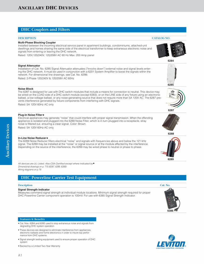
A1
ANCILLARY DHC DEVICES
DESCRIPTION CATALOG NO.
Multi-Phase Blocking CouplerInstalled between the incoming electrical service panel in apartment buildings, condominiums, attached-unitdwellings and homes sharing the same side of the electrical transformer to keep extraneous electronic noise andsignals from entering or leaving the DHC network.Rated: 120V,120/240V, 120/208V AC 60 Hz Max. 200 Amp panel
Signal AttenuatorInstallation of Cat. No. 6285 Signal Attenuator attenuates (“knocks down”) external noise and signal levels enter-ing the DHC network. It must be used in conjunction with a 6201 System Amplifier to boost the signals within thenetwork. For dimensional line drawings, see Cat. No. 6299.Rated: 2-Phase 120/240V & 120/208V AC 60Hz
Noise BlockThe 6287 is designed for use with DHC switch modules that include a means for connection to neutral. This device maybe wired on the LOAD side of a DHC switch module (except 6383), or on the LINE side of any fixture using an electronicballast, a low-voltage ballast, or any noise-generating source that does not require more than 5A 120V AC. The 6287 pre-vents interference generated by fixture components from interfering with DHC signals.Rated: 5A 120V 60Hz AC only
Plug-in Noise Filter�Electrical appliances may generate “noise” that could interfere with proper signal transmission. When the offendingappliance is isolated and plugged into the 6288 Noise Filter, which is in turn plugged into a receptacle, straynoise is filtered out, ensuring a clear signal. Color: Brown.Rated: 5A 120V 60Hz AC only.
In-Line Noise Reducer�The 6289 Noise Reducer filters electrical “noise” and signals with frequencies above and below the 121 kHz signal. The 6289 may be installed at the “noise” or signal source or at the module affected by the interference.Depending on the source of the interference, the 6289 may be wired phase to neutral or phase to phase.
All devices are UL Listed. Also CSA Certified except where indicated by�
Dimensional drawings on p. T15 (6287, 6288, 6289)Wiring diagrams on p.T8
DHC Couplers and Filters
6284
6285
6287
6288
6289
Description Cat. No.
Signal Strength IndicatorMeasures command signal strength at individual module locations. Minimum signal strength required for properDHC Powerline Carrier component operation is 100mV. For use with 6385 Signal Strength Indicator.
DHC Powerline Carrier Test Equipment
Features & Benefits
• Cat. Nos. 6284 and 6285 used to stop extraneous noise and signals fromdegrading DHC system operation
• These devices are designed to eliminate interference from appliances,electronic ballasts and home electronics in order to insure top perfor-mance from DHC systems
• Signal strength testing equipment used to ensure proper operation of DHCsystem
• Backed by a Limited Two-Year Warranty
6386
An
cill
ary
Dev
ices

All DHC modules are subjected to rigorous producttesting to ensure that they will provide a long servicelife in home installations. Tests include Heating, Over-Under Voltage, Component Failure, Operating PartDrop-Impact, Mold Stress-Relief Distortion, ImpactResistance, and Dielectric Withstand. The followingpages are a brief summary of the actual tests performedon DHC modules.
PRODUCT TESTING

PT1
PRODUCT TESTING
Testing of Programmers and ControllersHeating TestSample units were connected to rated voltages of 120V 60Hzuntil constant temperatures were reached on and around thedevice. All temperatures were measured using thermocouples.The highest temperature recorded on the device was 104°F,when the ambient temperature was 73° F. This was well withinUL performance standards. The system was designed tooperate within an ambient temperature range of 0°C–50°C(32°F–122°F).
Over-Under Voltage TestSample units were energized at an overvoltage of 132V ACuntil temperatures had stabilized. The voltage was then low-ered to the rated 120V 60 Hz for one hour, then lowered to anunder-voltage 102V, then operated several times. The deviceoperated continuously without damage at all voltage levels.
Component Failure TestSample units were wrapped in cotton, either shorted oropened, and subjected to rated voltage. No fires resulted.
Operating Part Drop Impact Test“As received” samples were dropped three times from aheight of three feet onto a hardwood surface. The unit wasdropped in different positions, each likely to produce harmfulresults. Operating parts were not affected.
Mold Stress-Relief Distortion TestEquipment samples and enclosures were put in a full draftcirculating air oven at 158°F for seven hours. The samples werethen carefully removed, allowed to return to room temperature,and examined for deterioration. There was no evidence ofsoftening of the enclosure materials when samples wereremoved from the oven, and no shrinkage, warpage or crackingwas evident after samples were returned to room temperature.
Impact Resistance TestTo assure the strength of the case, rockers and buttonsagainst sudden impact, a force of .75 foot-pounds wasapplied to several points on the unit’s surface without damage.
Dielectric Withstand TestSample units were wired and subjected to 1200 V AC for oneminute. Normal operation was not affected.
Signal Strength IndicatorMeasures command signal strength at individual modulelocations. Minimum signal strength required for proper DHCPowerline Carrier component operation is 100mV. Foruse with6385 Signal Strength Indicator.
All devices are UL Listed only, not CSA Certified.
DHC Test Equipment
Features & Benefits
• Signal strength testing equipment used to ensure proper operation ofDHC system
• Backed by a Limited Two-Year Warranty
6386
Pro
du
ctTe
stin
g

The purpose of the Troubleshooting section is to giveDecora Home Controls professionals and end-users an accurate, up-to-date and easy-to-understand viewof the DHC automation system's many strengths andpossibilities, as well as its operating characteristics.Leviton hopes that by using this information, yourknowledge of the system will expand so that you willbe able to take the steps necessary to help ensure topperformance of the DHC system.
DHC TROUBLESHOOTING GUIDE

Tro
ub
lesh
oo
tin
gTROUBLESHOOTING
TS1
IntroductionLeviton’s Decora Home Controls are built with high-qualitycomponents and tested to meet or exceed the strictest indus-try standards. They all periodically undergo redesign andupgrading as part of the company’s ongoing productimprovement program. New products are added as theybecome available to expand the capabilities of this powerfulhome control system. In addition, Leviton’s toll-free Techlinecan respond to questions from DHC customers.
IMPORTANT NOTE: All DHC devices incorporate micro-processor chips. Consequently, they must be suppliedwith stable 60 Hz AC power at 120 volts (+ or -10%).Consult the local utility company or a qualified electricalcontractor if the AC power at any facility does not meetthis requirement.
Fast-Track TroubleshootingMany of the common operating difficulties encountered withDecora Home Controls can be traced and corrected using theFast-Track Checklist below. If the difficulty is not identified andcorrected after proceeding through the list, continue to thesections that follow which describe how to examine specificaspects of the system.
Fast-Track ChecklistWhen a DHC network performs erratically, always check andconfirm that :• Ambient operating temperature does not drop below
32°F or rise above 122°F.• Appliance and lamp plugs are firmly inserted in receptacle
modules.• Appliances, lamps, and lighting fixtures have their switches
in the ON position.• Lamps and lighting fixtures have working bulbs.• Lighting loads controlled by Wall Switch Modules fall within
the 60–1000W range.• Transmitters (programmers and controllers) and receivers
(switch and receptacle modules) are set to the same Address Codes.
• A lamp or fixture containing a built-in dimmer cannot becontrolled by an Incandescent Wall Switch Module with dimming capabilities (Cat. Nos. HCM06/10, 6343, 6383, 16383).
• A neighbor that you share a utility transformer with does nothave a DHC or other automation system that is sendingcommand signals on the same House Codes (red dials)that you are using OR generating sufficient “electronicnoise” to interfere with your DHC signal transmissions.
• The following appliances, when operating, are generating“electrical noise” to the AC wiring system which might inter-fere with signal transmission and reception within the DHCsystem (see separate section):
— Wireless intercoms— Electric razors, hair dryers— Food processors, blenders, mixers, grinders— Vacuum cleaners, floor scrubbers, floor waxers— Wireless doorbells
— Electronic ballasts, television receivers— Laser printers— Non-FCC Class B computers— Some LPF CFL lamps
• No faulty connections exist between aluminum and copperconductors, especially in moist climates. These can cor-rode and create occasional shorts and arcs.
• No nominal static discharge has been transferred to the system controllers by touching them, especially during winter time in households where the air is cool and dry.Static discharge build-up will normally dissipate in a fewhours. Switching the circuit breaker for the affected con-troller on and off will restore normal operation immediately.
• The Power Lamp on HCA02-10E is lit.
DHC Operating CharacteristicsLighting System Types• Decora Home Controls low-voltage dimming modules are
designed to be used with magnetic (core and coil) trans-formers. These modules will not switch or dim lighting thatuses electronic (low voltage/high frequency) power supplytransformers.
To switch high-pressure discharge lamps (HID lighting, includ-ing mercury- and sodium-vapor and metal-halide lamp types),some success may be realized if a Cat. No. 6287 Noise Blockis installed as close to the lighting load(s) transformer(s) aspossible. This will keep electronic noises from contaminatingthe network.
Decora Home Controls can:—Switch low pressure discharge lamps—Switch, dim and brighten 120V Quartz lamps—Switch low voltage lighting systems (ON/OFF only) operat-
ing with a 60 Hz magnetic (core and coil) transformers onthe 120V side of the transformer.
Intercom systems that utilize existing home AC wiring forsound transmission will prevent proper operation of DecoraHome Controls. When in use, or when plugged in and left inthe talk position, such intercoms interfere with signal transmis-sion from programmers and controllers to modules. Intercomsthat employ their own separate wiring will not interfere with theoperation of Decora Home Controls.
The Decora Home Controls’ powerline carrier command signal can only travel through all wiring on the secondary sideof the primary transformer. Attempts to control an outbuilding(garage, barn, poolhouse) will not be successful if the out-building is not wired on the same side of the same transformeras the main building.
When a HCA02-10E System Amplifier Module is installed tocouple both legs of the 120/240V power supply, maximumsignal strength is ensured throughout the wiring grid, regard-less of which leg(s) the controller(s) is wired to. The presenceof the Cat. No. HCA02-10E should prevent intermittent opera-tion of Switch and Receptacle Modules and periodic failure ofresponse to command signals. See section titled EnsuringSignal Quality for details.
DHC Troubleshooting

TROUBLESHOOTING
TS2
Tro
ub
lesh
oo
tin
g
When More Thorough Examination is RequiredThere may be some instances when a more thorough check-out is required. If this is necessary, the Decora Home ControlsTester must be utilized. Carry out the following troubleshootingsteps using these devices in conjunction with the test buttonon the cat. no. HCA02-10E DHC System Amplifier whererequired, while referring to the procedures in the followingchapters.
This expanded troubleshooting section should be usefulwhen tracking down malfunctions and improper DecoraHome Controls operation. It can also serve as a generalreminder of proper installation when setting up Decora HomeControls in a home.
This section is by no means exclusive. There are certainproblems that are not covered here and there are certainsolutions that are not suggested. Even in such cases, thetroubleshooting methods should prove useful because theywill reliably lead you to positive conclusions about what isdefinitely not wrong. You can then turn your attention toremaining potential sources of trouble.
In simple terms, Decora Home Controls are installed as agroup that will consist of transmitters (your controllers andprogrammers) that send command signals over AC lines toreceivers (your switching modules—Wall ReceptacleModules, Wall Switch Modules, for example). The switchingmodules respond to commands from controllers by switchingtheir assigned loads ON or OFF, or by dimming and brighten-ing lighting.
Useful Troubleshooting ConceptsBased on the brief operating description just given, youmight expect that any improper operation encountered in aDecora Home Controls installation could be blamed on eitherthe controller, command signal, or receivers. That’s onlypartly true. Based on years of field work, the actual reasonsfor improper operation fall into six categories. Listed in orderof importance, these are:
1. Improper InstallationThis is by far the most common source of trouble. In particu-lar, receiver modules are often wired incorrectly (i.e., reversing the HOT LEAD and LOAD LEAD, overloading,underloading, and not setting proper address codes).
2. Improper or Insufficient Signal CouplingThis is the next most common source of trouble. It isabsolutely vital for strong command signals to reach everypart of the home’s electrical system from which controlledloads draw power.
3. MisapplicationThis is a problem that involves asking Decora Home Controlsto do the impossible (attempting to dim incandescent lightingusing a module that is not equipped for dimming, or attempt-ing to execute ALL LIGHTS ON commands to modules that
are not equipped to respond, or using the wrong receiver tocontrol a specific type of lighting, e.g., low-voltage lightingwith 6383).
4. Electrical “Noise” on AC LinesSome electrical loads trickle electronic “clutter” onto the AClines. This clutter alters or masks the Decora Home Controlscommand signal so that receiver modules either can’t recog-nize it or can’t read a complete command signal sequence.Examples of “noisy” loads include some dimmers, somecolor televisions, over-the-wire intercoms, high-speed motors,high frequency ballasts, and others. This is why the installa-tion of an HCA02-10E System Amplifier Module in everypanel is imperative to ensure adequate signal strength.
5. Electrical System AlterationsOccasionally Decora Home Controls that have been workingperfectly for years suddenly appear to malfunction for noapparent reason. Often, the cause rests with some changemade to the home’s electrical wiring, which affects commandsignal coupling, transmission or controller location.
6. Faulty Hardware
From time to time receivers, controllers or signal couplersbreak down and need to be replaced. Equipment failure,however, is the least likely cause of Decora Home Controlsoperational problems. All Decora Home Controls are essen-tially solid-state and therefore very reliable. In fact, mostDecora Home Controls returned to Leviton under warrantyare found to be operating perfectly when tested by our engineers.
7. Use of Incompatible Surge ProtectionUse only surge protective devices that are compatible withDHC powerline carrier signaling. They allow the signals topass through in their frequency range while filtering outother unwanted noise.
Based on the foregoing 7 items, a consistent troubleshootingmethodology has been developed. Usually, you will be ableto identify the problem by process of elimination, meaning you find out where the problem is by verifying where it isn’t. This is actually the fastest and most reliabletroubleshooting method because it quickly eliminates properly functioning Decora Home Controls devices fromsuspicion.
The DHC installer should document each installation, keep-ing accurate records of the products used, when they wereput in, the loads they control, the addresses used for eachtransmitter and receiver group, any difficulties encounteredduring installation and how they were solved. Should a sys-tem develop problems afterward, the installer should beginby asking the user if any modifications were made to thewiring grid and if any new equipment was introduced sincethe installation was completed.
DHC Troubleshooting

TROUBLESHOOTINGTr
ou
ble
sho
oti
ng
TS3
Troubleshooting Procedure Chart
CHECK (IN ORDER) HOW TO PROCEED
1.CONTROLLER UNITS SEE PAGE(TRANSMITTERS) TS5–TS6
2.SWITCHING SEE PAGEMODULES TS6–TS7
3.SIGNAL SEE PAGEQUALITY TS7–TS8
4.ELECTRONIC NOISE SEE PAGEINTERFERENCE TS8–TS9
DHC Troubleshooting

TROUBLESHOOTING
TS4
Tro
ub
lesh
oo
tin
g
DHC Troubleshooting
Checklist Procedures
Checklist implementation will take place in an orderedsequence. First, controllers will be checked. This is becauseit’s fairly easy to check for proper controller operation. Also, ifcontrollers are not working, other Decora Home Controlsdevices will not be issued command signals. The secondstep is to check modules that may be giving trouble. That’sbecause an inoperative module may be faulty itself or it mayprovide clues about problems elsewhere.
Having verified proper controller and module operation, thefinal steps in checking a home with Decora Home Controlswill be to verify adequate signal coupling, and to discover ifthere is electronic “noise” on the AC lines.
Necessary Troubleshooting and Testing EquipmentApart from the standard tools such as pliers, screwdrivers,etc., troubleshooting requires:
1. Cat. No. 6386 Signal Strength Indicator.
2. Testing procedures outlined in this guide.
3. Instruction sheets for all modules and controllers being tested.
CAUTION: IN SOME CASES TROUBLESHOOTINGPROCEDURES WILL HAVE TO BE CARRIED OUTUSING LIVE CIRCUIT CONDUCTORS. BE SURE TOEXERCISE EXTREME CARE AND TAKE PROPER PRE-CAUTIONS TO PREVENT ELECTRICAL SHOCK.
Signal Strength Indicator
Cat. No. 6386

TROUBLESHOOTINGTr
ou
ble
sho
oti
ng
TS5
DHC Troubleshooting
Confirming Proper Operation of Control Units
Testing the Plug-In Controller(Cat. No. 6320-Table Top Controller)1. Set the controller to transmit command signals to address
P1. (For more information on how to address controlleroutput, see the instruction manual provided with yourcommand unit.) The controller must be set to transmit toP1 because this is the only address code the Cat. No.6386 Signal Strength Indicator can monitor.
2. Plug Cat. No. 6386 Signal Strength Indicator into the freehalf of the duplex receptacle that powers the controller(receptacle must be single-branch-circuit-wired). If thecontroller is supplied with line current by a single recepta-cle, plug the 6386 into some other receptacle on thesame branch circuit.
3. Transmit “P1 ON” and “P1 OFF” from the controller you are testing.
4. Observe the signal strength level shown by the Cat. No.6386. Signal strength must be 2 volts minimum atthe Hi-Range setting. If the controller transmits less than 2volts of signal, it is faulty and must be replaced. If the yellow ERROR CONDITION indicator is lit, it means thereis electronic “noise” on the line that will mask commandsignals sent by Decora Home Controls controllers, or prevent them from ever being sent by the controller. Thesource of this noise will have to be identified and eliminated or filtered out. See section titled ElectronicNoise Interference for details.
5. Observe if signal lamp of HCA02-10E blinks. It must blinkto indicate that the signal is being received and amplified.
6. Set the controller to transmit the desired address codesfor return to normal operation. Testing is complete.
Testing Wired-In Controllers1. Interrupt power to the wall-mounted controller you are
testing at fuse or circuit breaker.2. Set the controller you are testing to transmit to address
P1. (For more information on addressing controller output,see the instruction sheet provided with the unit.)
3. Install a pair of 6 to 8 inch testing leads, made of AWG #s 20–12 solid or stranded wire, as shown in Figure 1. Be sure that the metal ends of the testing leads are nottouching each other, any metal fittings, tubing, conduit or boxes.
4. Restore power to controller being tested at fuse or circuit breaker.
5. Connect the Cat. No 6386 to testing leads using alligatorclips as shown in Figure 1.
6. Observe the signal strength level shown by the Cat. No.6386 Signal Strength Indicator. Signal strength must be2V minimum at the Hi-Range setting. If the controllertransmits less than 2 volts, it is faulty and must bereplaced. If the yellow ERROR CONDITION indicator islit, it means there is electronic “noise” on the line that willmask the signal or prevent it from being transmitted bythe controller. The source of this noise will have to beidentified and eliminated or filtered out. See the sectiontitled Electronic Noise Interference for details.
7. Observe if the HCA02-10E signal lamp blinks in responseto signal. It must blink to indicate that the signal is beingreceived and amplified.
8. Turn off power at fuse or circuit breaker to the controlleryou are testing. Remove testing leads and properly wireand reinstall the controller or replace it if it was found tobe faulty.
9. Restore the controller to transmit the desired addresscodes for return to normal operation.
10. Restore power at fuse or circuit breaker. Testing is complete.
Signal Strength Indicator Test Set Up
NOTE: These testing leads will provide a signal source forthe Cat. No.6386 Signal Strength Indicator using alligatorclips as shown in Figure 1. As an alternative to installing test-ing leads when checking 120V wall-mounted controllers, youcan monitor signal strength by plugging the Cat. No. 6386into a 120V receptacle that draws power from the samebranch circuit as the controller you are testing.
WARNING: WHEN POWER IS RESTORED, THE CIR-CUIT CONDUCTORS, CONTROLLER LEADS, ANDTESTING LEADS WILL BE LIVE. BE SURE TO EXERCISE EXTREME CARE AND TAKE PROPER PRECAUTIONS TO PREVENT ELECTRICAL SHOCK.When testing the Cat. No. HCC1A-1TW and 16400/16450-1Aseries Wall Mounted Controllers, IT WILL NOT BE POSSIBLETO GET AN ACCURATE SIGNAL USING THE CAT. NO. 6386SIGNAL STRENGTH INDICATOR. The 6386 can only read P1ON and P1 OFF command signals. The HCC1A-1TW and16400/16450-1A series can only transmit ALL LIGHTS ONand ALL OFF signals to a selected Letter Code. If you sus-pect that a HCC1A-1TW or 16400/16450-1A series controlleris malfunctioning, test it by attempting to control a modulethat responds to ALL LIGHTS ON, set to the same LetterCode as the controller, that draws current from the samebranch circuit as the controller. Only Cat. Nos. HCM06 andHCM10, 6290, 6291 and 6293, 6343, 6375, 6376,6383,16293, 16383, can respond to ALL LIGHTS ON. Allreceiver modules respond to ALL OFF.
For more information, refer to the instruction sheets providedwith the HCCxx series and 16400/16450 series units.
WALL MOUNTEDCONTROLLER
TEST LEADS
CAT. NO. 6386SIGNAL STRENGTHINDICATOR
ALLIGATORCLIPS
SCENE 1
SCENE 3
SCENE 2
SCENE 4
SCENE 5 SCENE 6
SCENE 7 OFF
Figure 1

TROUBLESHOOTING
TS6
Tro
ub
lesh
oo
tin
g
DHC Troubleshooting
Additional Notes–Testing Wired-in Controllers
[NOTE—All HCCxx series and 16400/16450 Wall-MountedControllers (see Catalog Listing) monitor the AC line for pres-ence of Decora Home Controls command signals already onthe line from another source. [If they detect such a signal theywill hold off their own signal transmission until the line is clear.Likewise, they will not transmit command signals if there isnoise on the line.] However, Cat. Nos. 6315 and 6316 DryContact Transmitters monitor the line by means of a special“polling” process. Consequently, if any two of these controllersare transmitting to the same NUMBER CODE (regardless ofthe House Code) at the same time, both signal transmissionswill be lost. See the instruction sheet provided with Cat. Nos.6315 or 6316 for more information.
Wall-mounted controllers that are equipped to dim also trans-mit ON and OFF commands that can be picked up by ANYDecora Home Controls switch module. However, DIM andBRIGHT commands can only be picked up by Cat. Nos.HCM06 and HCM10, 6290, 6376, 6343, 6381, 6383, 16383and HCP03.
NOTE: ONLY THE MODULES LISTED CAN RESPOND TODIM/BRIGHT COMMANDS. DIMMING WILL NOT BE POSSI-BLE WITH MODULES OTHER THAN THOSE LISTED .
If testing the Cat. Nos. HCCPG-1TW and 6312 Programmers,check to be certain that faulty programming is not responsiblefor improper operation of the controller. For more information onchecking programming and general operation of theProgrammers, see the instruction sheet supplied with the unit.
No more than 4 Controllers should be installed on a single branch circuit.
Conclusions From Testing Controllers
If testing of the controller reveals:
• The controller is transmitting command signal at a strength of2V or more,
• There is no “noise” on the AC line supplying power to thecontroller, or
• Programmed schedules (if applicable) entered in the controller are correct, then the reason for any erratic orimproper operation of Decora Home Components is NOTTHE FAULT OF THE CONTROLLER. It will be necessary toproceed with testing of modules and coupling equipment.
The following testing procedure is applicable to all DecoraHome Controls modules in a general way. However, becauseof the number of module types available, there will inevitablybe certain operating characteristics unique to individual modules that cannot be covered in this manual. Therefore,when testing module operation, use the following procedure asa guide, but be sure to also check the instruction sheets pro-vided with the modules you will be checking.
Step-By-Step Testing
1. Confirm that the module is powered.
2. Confirm that the module is wired exactly as shown in the dia-gram on the instruction sheet.
3. Confirm that the load being controlled is in proper workingorder (i.e., check for burned-out bulbs, etc.).
4. Confirm that the module is set to the proper House Codeand Number Code.
5. Confirm that the load being controlled does not exceed themodule rating (including start-up).
6. Check to see whether the module “chatters”, instead ofswitching properly, when it receives a command signal.Modules may “chatter” because line voltage is too low, sig-nal strength is insufficient, or wiring connections are bad. If amodule chatters when these conditions do not exist, it isfaulty and must be replaced.
7. Confirm that the intended application of the module is possi-ble based on the limitations (if any) outlined in the unit’sinstruction sheet. For instance, confirm that dimming isn’tbeing attempted using a module that can’t dim.
IMPORTANT: If a check of items 1-7 above doesn’t uncoverthe reason for improper operation, the fault does not liewith the module. Assuming you have already confirmedthat your command unit works properly, proceed withsteps 8A, B and C.
8. Check for adequate command signal strength at the mod-ule location as follows:
A–Press the test button on the HCA02-10E System AmplifierModule.
B–Using the Cat. No. 6386 Signal Strength Indicator at thereceptacle locations, check the command signal amplitude.Signal strength must be 100 mV minimum. If there is lessthan 100 mV of signal present, check Signal Bridge installa-tion and operation. If no Signal Bridge is present, it is nec-essary to install one to assure sufficient signal strengththroughout the wiring system. See the section titledEnsuring Signal Quality for details.
C–If the yellow ERROR CONDITION indicator is lit on theCat No. 6386, there is electronic noise present on the ACline that interferes with proper module operation. Thesource of this noise must be identified and eliminated, or fil-tered out. See the section titled Electronic NoiseInterference for details.
Additional Notes-Testing Modules
The duplex Cat. Nos. 6296 and 6298 DHC receptacle moduleshave “sense control” built in. The sense control feature allowsany load plugged into a receptacle module to be turned on oroff manually using the load’s own ON / OFF switch.
Occasionally, when receptacle modules equipped with sense-control are used to control transformer-equipped loads, atrickle of electrical “noise” (emitted when the transformer is off)will trigger the module’s sense-control circuit. This makes itappear that the controller cannot be turned off, when, actually,the load is being turned off and then back on again only mil-liseconds later by the “noise” from the offending transformer.
If this occurs, the best solution is to replace the existing mod-ule with a similarly rated module that does not have sense con-trol, such as Cat. Nos. 6296 and 6298 Wall-mountedReceptacle Receivers.
Confirming Proper Operation of Switching Modules

TROUBLESHOOTINGTr
ou
ble
sho
oti
ng
TS7
DHC Troubleshooting
Where a dimming application is required, ONLY the followingmodules will respond to DIM and BRIGHT commands: Cat.Nos. 6290, 6376, 6381, 6383, 16383, 6343, HCM06,HCM10 and HCP03.
IMPORTANT: If ALL LIGHTS ON commands are issued,ONLY Wall Switch modules and Fixture Relay moduleswill respond. Wall Receptacle modules WILL NOTrespond to ALL LIGHTS ON commands.
Conclusions From Testing ModulesAssuming you have verified proper controller performance,and also assuming you have checked module instructionsheets and performed the module troubleshooting steps andthe cause for malfunction has not yet been revealed, thenimproper operation of your Decora Home Controls installationis due to intermittent electric “noise” in the AC system orinadequate signal coupling. The following sections, CouplingPhases on the Secondary Side of the Single Transformer andIdentifying and Eliminating Electrical Noise, will help in correcting noise/coupling problems.
Ensuring Signal Quality
Coupling Phases in a Home with Sub Panels Downlinefrom the Main Panel. See Figure 2
The Cat. No. HCA02-10E System Amplifier Module is used toconnect both legs of a 120/240 volt wiring system in resi-dences to provide an essential path for command signals totravel throughout the entire AC wiring system.
In a typical 120/240 V three-wire system, the controller coulddraw its power from line 1. As a result, the signal strengththroughout the line 1 side of the circuit network should be verygood. Signal strength may not be as good on the line 2 side,due to signal strength lost during the crossover from line 1 toline 2. In order to ensure good signal strength on both sidesof the wiring system, a Cat. No. HCA02-10E System AmplifierModule should be installed as shown in the figure below.
In some large 120/240V three-wire systems, the DHC command signal is attenuated (meaning it fades away). Evenin some smaller systems the DHC signal is attenuated by linelosses that result from deteriorating insulation or a large number of loads. In addition, aluminum wire and servicecable oxidize rapidly with normal use causing noise on theAC power line.
This can be avoided by:
1. Sealing the aluminum wires at connection point.
2. Making sure all connections are tight.
3. Using only copper wire, if possible.
NOTE: A Cat. No. HCA02-10E System Amplifier Moduleshould be installed in all panels in every DHC installation.
HCA02-10E
BLACK LEAD
RED LEAD
LINE 2LINE 1N
WHITE LEAD
120V LOAD
CONTROLLER
15ACIRCUITBREAKER
Figure 2—Typical 120/240V Residential Power Supply

TS8
Tro
ub
lesh
oo
tin
g
DHC Troubleshooting
Figure 3 on page 38 shows 120/240V three-wire system aswell as 120/208V three-phase wiring schematics for the Cat. No. 6201 Signal Amplifier. Troubleshoot as follows:
NOTE: It is assumed you have verified proper functioningof controllers and receiver modules before checking sig-nal coupling.
1. Confirm that there actually is a HCA02-10E present.
2. Confirm the HCA02-10E is properly wired exactly as shown.
3. Confirm that the 15 Amp breakers to the HCA02-10E are ON.
4. Confirm that green power lamp is on.
5. Confirm that power lamp blinks in response commandsissued by all DHC devices.
6. Press the test button on HCA02-10E.
7. Check signal strength at various module locations on theline side that powers the controller using a cat. no. 6386Signal Strength Tester. Signal amplitude must be at least100 mV for proper module operation.
NOTE: IF LESS THAN 100 mV OF SIGNAL APPEARS AT ANY OF THE RECEIVER LOCATIONS TESTED, CONTACTYOUR NEAREST LEVITON TECHNICAL SUPPORT REPRESENTATIVE.
Electronic Noise InterferenceGeneral ConsiderationsIdeally, all AC residential wiring system should supply clean,stable 60Hz line current at the required voltage. Unfortunately,in the real world, this just isn’t true. In fact, there are all sortsof electrical spikes, sags, clutter, and AC waveform distur-bances afflicting most power supplies. Regardless of theircause, we can lump all of these disturbances on the AC linesunder the general classification
Electrical NoiseDepending on its frequency, amplitude and type, this noisemay interfere with proper functioning of the Decora HomeControls either in whole or in part.
This is because the Decora Home Controls command signalis a very precise binary code transmitted on the AC powersine curve. As a result, the controller must have access to aclean AC sine wave on which to deposit signal pulses, andmodules must be able to monitor a clean AC sine wave fromwhich to read the command signal pulses.
Now, of course, it’s not reasonable to expect that any AC sys-tem will be completely noise free. Therefore, all Decora HomeControls components have been designed to tolerate a consid-erable amount of noise and still continue functioning perfectly.
Leviton DHC receivers have been equipped with a specialcircuit called Intellisense™ Gated Automatic Gain Control.Intellisense provides DHC receiver modules with outstandingnoise immunity during the critical “zero-crossing” interval ofthe 60Hz AC sine wave. This is the point where commandsignals are sent, and it’s also the point where the receiverscould be disrupted by electrical interference.
Some receivers from other manufacturers have a less sophis-ticated form of gain control, but it can cause a loss of sensi-tivity to command signals. Only Leviton DHC receivermodules have Intellisense Gated Automatic Gain Control. To
begin with, all command pulses are situated at zero crossingbecause that’s the quietest point of the AC sine wave. (Bycontrast, the 90 degree and 270 degree peaks on the ACsine wave are noisiest.) In addition, the command signalsthemselves are actually a very complex, structured binarycode that occupies 22 cycles on the power line. It’s repeatedevery time a signal is sent. Consequently, there is very littlechance that any module will mistake stray electrical noise forreal command signal because it’s statistically improbable fornoise to perfectly mimic a command signal sequence.
Nevertheless, despite these precautions, there are caseswhen the electrical noise is so strong or so wide spread that itsimply overwhelms the noise protection designed intoDecora Home Controls components. This noise threshold hasexceeded acceptable limits if, during signal strength testing,the yellow “ERROR CONDITION” indicator on the Cat. No.6386 Signal Strength Indicator lights up.
In addition, the HCCxx series, 6315, 6316 and 16400/16450series controllers constantly monitor the AC lines whichpower them for the presence of command signal.
The reason these controllers monitor the powerline is to pre-vent superimposing their own command signal transmissionsover commands which are already simultaneously on the ACline from other controllers. So if one of the above-mentionedcontrollers sees a command signal on the line, it will wait forthe end of the signal before beginning to transmit its owncommand sequence.
However, if electrical noise is strong enough to register on theCat. No. 6386 “ERROR CONDITION” indicator, it is alsostrong enough to be mistaken for command signal by thesecontrollers. If that happens, the controllers will wait for thenoise to clear before sending their command signals. But ifthe noise doesn’t clear up, then the command signals maynever be released by the controller. This is bad on twocounts: Decora Home Controls components stop functioningproperly AND the mistaken impression is created that a con-troller is defective because it won’t transmit when, actually,the controller is working perfectly but is being blocked fromtransmitting by noise.
Another possibility is that the noise will stop. But it may stop afew minutes after a controller originally tried to transmit acommand. During those few minutes, the controller has beenstoring that command signal, patiently waiting for the noise toclear before transmitting it. So when the noise stops, the sig-nal is transmitted, and the appropriate load responds as itshould. However, the user will generally not associate thisswitching operation with the command he or she tried tosend a short while ago, so the impression is created that“loads are going on and off by themselves” when this is notreally true at all.
The bottom line is that this noise must be corrected in orderfor Decora Home Controls to function properly.
There is no hard and fast rule for identifying which loads gen-erate noise. Noise sources vary from one installation toanother. Some have no noise troubles, some have a few,occasionally, noise can be a real problem. Experience hasshown, however, that the following list of load types are themost likely sources of noise interference.
TROUBLESHOOTING

TS9
Wireless Powerline-Carrier Intercoms: These are inter-coms which use existing AC lines for voice transmission.They encode the speaker’s voice as a series of powerlinecarrier pulses which are then picked up and recreated atreceiving intercoms. This is the one type of load which istotally incompatible with the Decora Home Controls. It cannotbe filtered or relocated. In order for Decora Home Controls towork properly, any and all wireless powerline-carrier inter-coms must be removed. There is no other solution to thenoise problem created by these units.
Electronic Ballasts/Transformers: These are occasionallynoisy when first installed, but they become noisier as theyage. In particular, electronic ballasts which are approachingfailure at the end of a 3–5 year service life put out overwhelm-ing electrical noise.
Instant-On Color TV Sets: Many of these sets employdegaussing mechanisms to sweep static electricity off theirpicture tubes and dump it as noise through their line cords.
Computer Printers: Generally, these devices will create dis-turbances only as they are actually printing.
Video Display Terminals: Most terminals do not normallytransmit noise. However, older terminals, especially older ter-minals on the verge of failure, can be noisy.
High-Speed Motor Loads: Devices of this sort which can be noisy include grinders, motor-driven paint sprayers, centrifuges, vacuum cleaners, hair dryers, electric razorsblenders, mixers and food processors.
Dimmers: In particular, larger incandescent dimmers canoften cause disturbances on the AC line.
Older Contactor Relays: As springs weaken in agingdevices, contact bounce causes disturbance of the ACwaveform.
Piezoelectric Devices: Generally, these cause sharpmomentary spikes on the AC line.
Any powerline carrier devices other than the DecoraHome Controls: If any devices or systems communicate bymeans of powerline carrier signals they will interfere withDecora Home Controls transmission and reception.
Improperly installed Decora Home Controls: In thosecases where Decora Home Controls are installed withimproper termination of neutral leads (i.e., mistakenly connected to ground), the incorrectly installed devices willgenerate noise.
Locating and Eliminating Sources Of NoiseIn order to locate electrical noise, use test button of HCA02-10E System Amplifier Module to send signal and a Cat. No.6386 Signal Strength Indicator will be needed.
The Cat. No. 6386 cannot just be connected to line currentand produce an “ERROR CONDITION” noise indication ifnoise is present. Instead, the Cat. No. 6386 must pick upcommand signals which are being disrupted by noise beforeits yellow “ERROR CONDITION” indicator can light.
Once you have identified the noise source by means of theprocedures to be described shortly, you have several optionsto choose from for eliminating the noise:
1. If possible, simply remove the noisy equipment and take itout of service permanently. (This is the only option withwireless intercoms).
2. If the noise is coming from a 125V load equipped with aline cord (for instance, a TV set), use a Cat. No. 6288 Plug-In Noise Filter. This is a small device, about the size of acigarette pack. Simply plug the offending appliance intothe 6288, and then plug the 6288 into a standard 125Vreceptacle. The 6288 will allow line current to feed theappliance as normal, but will filter out any electrical noisebeing transmitted from the load plugged into itself.
3. If the source of noise is a 125V wired-in load, a Cat. No.6287 Noise Block must be mounted in its own wallbox orother electrical enclosure as close to the offending load aspossible. The 6287 is equipped with leads that are con-nected to branch circuit conductors at the same point asthe power leads for the offending load. The 6287 leadsmay be connected phase to neutral for noisy 120 voltloads. If the offending loads are especially noisy, it may benecessary to use two 6287s wired in parallel to completelyeliminate the interference.
4. HID lighting may also interfere with DHC modules.Generally, the interference will affect only the DHC switchmodule actually controlling the HID lighting, but in someinstances other DHC modules may be affected as well.The interference usually occurs when the HID lighting isshut off. At shutdown, the HID lighting leaks a great deal ofelectrical noise which often switches the DHC module con-trolling the lighting back ON. The appearance is that theDHC module cannot be turned off from controllers.Actually, it does go off, but is then immediately turned backon by the electrical noise from its HID fixture.
To locate noisy loads, press test button on HCA02-10E tosend test signals repeatedly. When the Cat. No. 6386 SignalStrength Indicator yellow “ERROR CONDITION” indicatorlights up, start turning off breakers for branch circuits draw-ing power off the same phase as the AC lines you are moni-toring. When you turn off a particular breaker or group ofbreakers which cause the “ERROR CONDITION” light to goout, make a note of which branch circuits they disable.
Once you have identified all sources of noise, apply one ormore of the three remedies specified earlier in this chapter.
DHC Troubleshooting
Tro
ub
lesh
oo
tin
gTROUBLESHOOTING

Decora Home Controls provide the outstanding flexibilityneeded to create a home automation system withcustomized control capability. Whether it's remotecontrol capability for convenience, motion detectionfor enhanced home security, automated remote controlof lighting and appliances for energy savings, or 3-wayand 4-way light switching without expensive rewiring;there's an easy-to-install, cost-effective DHC systemfor any application.
The following section provides typical examples of DHClayouts. These examples are just some of the manypossible DHC applications that meet the needs ofsmall-scale or large-scale home automation systems,and everything in-between.
DHC offers the widest choice in Home Controls.
DHC APPLICATIONS
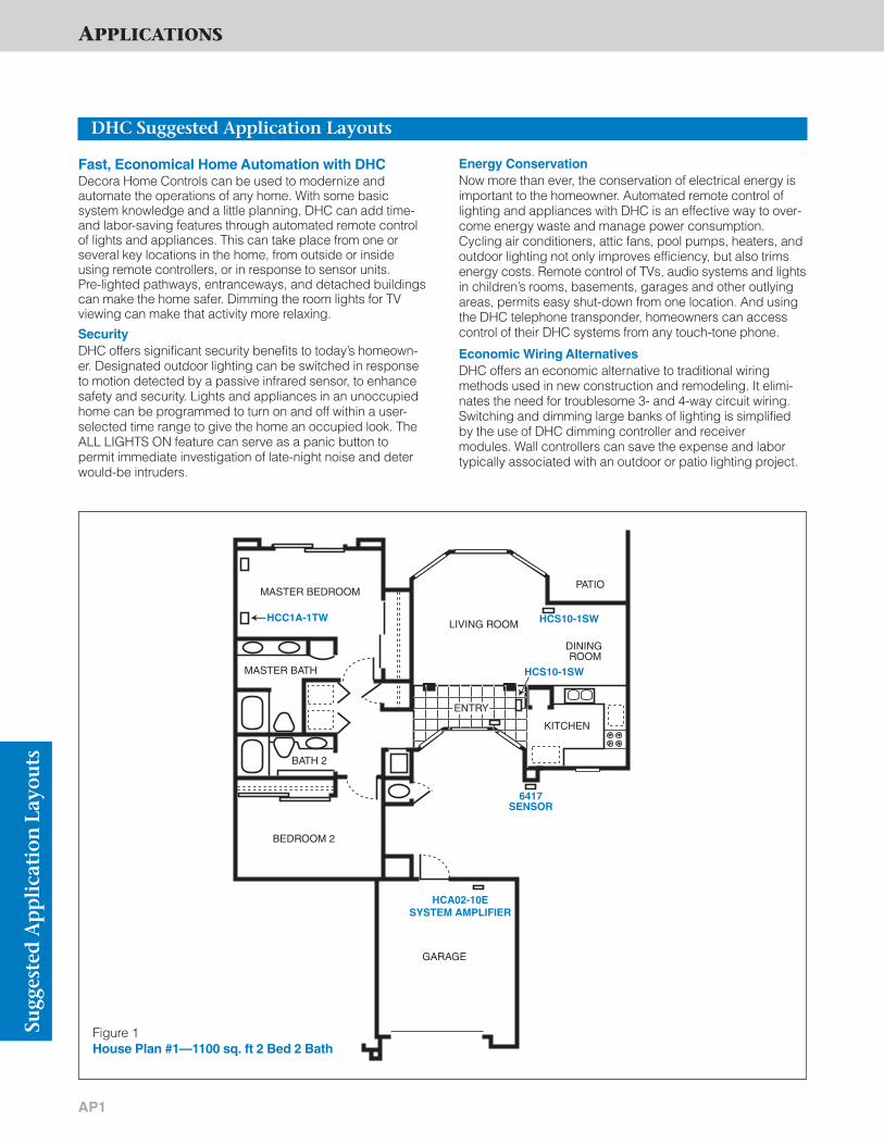
APPLICATIONSSu
gges
ted
Ap
pli
cati
onLa
you
ts
AP1
Fast, Economical Home Automation with DHCDecora Home Controls can be used to modernize and automate the operations of any home. With some basic system knowledge and a little planning, DHC can add time-and labor-saving features through automated remote controlof lights and appliances. This can take place from one or several key locations in the home, from outside or insideusing remote controllers, or in response to sensor units. Pre-lighted pathways, entranceways, and detached buildingscan make the home safer. Dimming the room lights for TVviewing can make that activity more relaxing.
Security DHC offers significant security benefits to today’s homeown-er. Designated outdoor lighting can be switched in responseto motion detected by a passive infrared sensor, to enhancesafety and security. Lights and appliances in an unoccupiedhome can be programmed to turn on and off within a user-selected time range to give the home an occupied look. TheALL LIGHTS ON feature can serve as a panic button to permit immediate investigation of late-night noise and deterwould-be intruders.
Energy ConservationNow more than ever, the conservation of electrical energy isimportant to the homeowner. Automated remote control oflighting and appliances with DHC is an effective way to over-come energy waste and manage power consumption.Cycling air conditioners, attic fans, pool pumps, heaters, andoutdoor lighting not only improves efficiency, but also trimsenergy costs. Remote control of TVs, audio systems and lightsin children’s rooms, basements, garages and other outlyingareas, permits easy shut-down from one location. And usingthe DHC telephone transponder, homeowners can accesscontrol of their DHC systems from any touch-tone phone.
Economic Wiring AlternativesDHC offers an economic alternative to traditional wiring methods used in new construction and remodeling. It elimi-nates the need for troublesome 3- and 4-way circuit wiring.Switching and dimming large banks of lighting is simplifiedby the use of DHC dimming controller and receiver modules. Wall controllers can save the expense and labortypically associated with an outdoor or patio lighting project.
HCS10-1SW
HCA02-10ESYSTEM AMPLIFIER
HCS10-1SW
6417SENSOR
HCC1A-1TW
MASTER BEDROOM
BEDROOM 2
GARAGE
PATIO
LIVING ROOM
DINING ROOM
KITCHEN
MASTER BATH
BATH 2
ENTRY
Figure 1 House Plan #1—1100 sq. ft 2 Bed 2 Bath
DHC Suggested Application Layouts

APPLICATIONS
AP2
FAMILYROOM
GARAGE
FIRST FLOOR SECOND FLOOR
HCS10-1SWHCC4D-1TWHCCS7-1TW
HCS10-1SW
HCM10- 1SW
HCM10-1SW
HCA02-10E System Amplifier
6417Sensor
BEDROOM4
KIT
CH
EN
MA
ST
ER
BAT
H
HA
LL
DININGROOM
LIVINGROOM
BEDROOM3
MASTERBEDROOM
BALCONY RETREAT/OPTIONAL
BEDROOM 5
BEDROOM2
BATH2
WALK-INCLOSET
WALK-INCLOSET
HCS10- 1SW
HCS10- 1SW
Figure 2—House Plan #2—3,000 sq. ft. 4 Bedroom, 3 Bath
Figure 3—Typical Layout for Residence
6227-I
HCC4A- 1TW
HCM10-1SW
HCM10- 1SW
6417-W
Workshop
Kitchen Light
Master BR Light
Porch Light
Driveway
Storage
Living RmLight
Panel
6227-I
HCM10-1SW
Front Door
HCCS7- 1TW
HCM10- 1SW
HCA02-10E SystemAmplifier
Sugg
este
d A
pp
lica
tion
Layo
uts
DHC Suggested Application Layouts

APPLICATIONSSu
gges
ted
Ap
pli
cati
onLa
you
ts
AP3
DHC Suggested Application Layouts
HCA02- 10E
HCC1A- 1TW*
Set Code D1(Master Bedroom)
6417
Set Code D1(Outdoors)
63136314
Set Code D1(Plug-In Recep.)
HCS10- 1SW
MAIN PANEL
6291-WI
Set Code D1(Front Entry)
Set Code D2(Back Patio)
Set Code D3(Kitchen)
HCM10- 1SW
Controllers Receivers
SystemAmplifier
HCS10- 1SW
Figure 4—Typical Economy Package
HCA02- 10E
HCCS7- 1TW*
Set Code C1(Front Door)
(Kitchen) (Garage Door)(Patio Door)
(Master Bedroom)
HCCPG- 1TW
Set Code C1-C8(Kitchen)
SystemAmplifier
63136314
Set Code C1(Plug-In Recep.)
(Home & Car)
HCS10- 1SW
MAIN PANELControllers Receivers
Set Code C1-C4(Front Entry) (Front Lights)(Back Lights)
(Garage Lights)
Set Code C2(Stairway) (Hallway)
(Master Bedroom)
Set Code C8(Dining Room)
HCM10- 1SW
6291-WI6280
Figure 7—Typical Premium Package
HCA02- 10E
HCC1A- 1TW*
Set Code A1(Front Door)
6320
Set Code A1(Kitchen)
63136314
Set Code A1(Plug-In Recep.)
HCS10- 1SW
MAIN PANEL
6291-WI
Set Code A1(Front Entry)
Set Code A3(Dining Room)
HCM10- 1SW
Controllers Receivers
SystemAmplifier
HCS10- 1SW
Figure 5—Typical Value Package
HCA02- 10E
HCCS7- 1TW*
Set Code B1(Front Door)
(Master Bedroom)
6312
Set Code B1(Kitchen)
63136314
Set Code B1(Plug-In Recep.)
HCS10- 1SW
MAIN PANELControllers Receivers
6291-WI
Set Code B1(Front Entry) (Front Lights)(Back Lights)
Set Code B3(Dining Room)
MS00R- 10W
HCM10- 1SW
SystemAmplifier
Figure 6—Typical Medium Package
CONTROLLERS RECEIVERS1–HCC1A-1TW Controller 3–HCS10-1SW Switches1–6417 Passive Infrared or HCM10-1SW Dimmers
Controller1–6313 Hand-Held Remote Controller1–6314 Plug-In Transceiver
1–HCA02-10E System Amplifier*OPTIONS: 1–HCC10-1TW—One Address—ON/OFF
Controller
CONTROLLERS RECEIVERS1–HCC1A-1TW Controller 3–HCS10-1SW Switch1–6320 Table Top Controller or HCM10-1SW Dimmer1–6313 Hand-Held Remote Controller1–6314 Plug-In Transceiver
1–HCA02-10E System Amplifier*OPTIONS: 1–HCC1A-1TW—One Address—ALL ON/ALL OFF
Controller1–HCC2D-1TW—Two ON/OFF & One Dimmer1–HCC4D-1TW—Four ON/OFF & One Dimmer1–HCC4A-1TW—Three ON/OFF & One ALL ON/OFF
CONTROLLERS RECEIVERS2–HCCS7-1TW Controllers 4–HCS10-1SW Switches1–6312 Wall Mount or HCM10-1SW Dimmers
Programmer1–6313 Hand-Held Remote Controller 1–6314 Plug-In Transceiver 1–MS00R-10W Multi Remote
1–HCA02-10E System Amplifier*OPTIONS: 1–HCC4D-1TW—Three ON/OFF & One Dimmer
1–HCC4A-1TW—Three ON/OFF & One ALL ON/OFF
CONTROLLERS RECEIVERS5–HCCS7-1TW Controllers 1–6280 Duplex Wall Receptacle1–HCCPG-1TW DHC Toscana 10–HCS10-1SW Switches
Deluxe Programmer or HCM10-1SW Dimmers2–6313 Hand-Held Remote
Controller1–6314 Plug-In Transceiver
1–HCA02-10E System Amplifier*OPTIONS: 1–HCC4D-1TW—Four ON/OFF & One DIMMER
1–HCC4A-1TW—Three ON/OFF & One ALL ON/OFF

APPLICATIONS
AP4
DHC Suggested Application Layouts
Sugg
este
d A
pp
lica
tion
Layo
uts
HCA02- 10E
HCC4D- 1TW*
Set Code E1(Front Door)
SystemAmplifier
6312
Set Code E1(Kitchen)
63136314
Set Code E1(Plug-In Recep.)
HCS10- 1SW
MAIN PANEL
6291-WI
Set Code E1(Front Entry)
(Living Room)
Set Code E2(Kitchen)(Garage)
Set Code E3(Dining Room)
HCM10- 1SW
Controllers Receivers
HCS10- 1SW
Figure 8—Typical Convenience Package
HCA02- 10E
HCC1A- 1TW*
Set Code F1(Garage Door)
63136314
Set Code F1(Plug-In Recep.)
6337
6337
MAIN PANEL
Set Code F1(Automatic
Garage Door)
Set Code E3(Automatic Front Gate)
Controllers Receivers
SystemAmplifier
Figure 9—Typical Dry Contact Package
6313
6314HCS10-1SW
Figure 10—Ideal for the Elderly and Physically-Challenged
HCC1A-1TW
HOUSE
300 FT.
GREENHOUSE
HCS10-1SW
Figure 11—Outbuilding/Greenhouse
CONTROLLERS RECEIVERS1–HCC4D-1TW Four ON/OFF 5–HCS10-1SW Switches
and One DIMMER or HCM10-1SW Dimmers1–6313 Hand-Held Remote
Controller1–6314 Plug-In Transceiver
1–HCA02-10E System Amplifier*OPTIONS: 1–HCC4A-1TW–Three ON/OFF & One ALL ON/OFF
1–6312 Wall Mount Programmer
CONTROLLERS RECEIVERS1–HCC1A-1TW Controller 2–6337 Universal Modules1–6313 Hand-Held Remote 2–5325 Standard Receptacles
Controller1–6314 Plug-In Transceiver
1–HCA02-10E System Amplifier*OPTIONS: 1–Momentary or Maintained Contact Closure
2–With or Without Alarm
6313 Handheld Remote Controller sends addressed ON/Off signal to 6314 transceiver via “Radio Frequency” (RF) which sends ON/OFFsignal to single-pole switch receiver HCS10-1SW on power line.
The HCC1A-1TW switch controller sendsaddressed ON/OFF signal to HCS10-1SWswitch receiver on power line, convenientlycontrolling greenhouse lighting from the house.
UNIVERSALDESIGN
CONVENIENCE

APPLICATIONSSu
gges
ted
Ap
pli
cati
onLa
you
ts
AP5
DHC Suggested Application Layouts
HCC1A-1TW
6337
BARK!BARK!
Figure 12—Pesky Barking Dog Control
6314-W
6313
HCS10- 1SW
Figure 13—Wood Burning Stove Vent
When that pesky dog next door is barking simplypress the HCC1A-1TW ALL LIGHTS ON/ALL OFFSWITCH CONTROLLER to send ON/OFFaddressed signal to 6337 on power line. 6337sends low voltage signal “telling” the sprinklervalve to open or close.
The homeowner can use a 6313 universal lowvoltage module to send “RF” ON/OFF signalwith address code to 6314-W remote trans-ceiver, which sends ON/OFF over power line to HCS10-1SW, switch receiver which opens or closes motorized stove vent.
6314HCS10-1SW
6313
HCS10-1SW
Figure 14—Remote Controlled Boathouse Lights
As boat comes to dock at night, homeowner selects “ON”address on 6313 handheld remote controller. The signaltravels via “RF” to 6314-W remote transceivers at BoatHouse and sends an address command via power line toHCS10-1SW switch receivers to light Boat House/Dock area.
COMFORT
SAFETY

APPLICATIONS
AP6
DHC Suggested Application Layouts
Sugg
este
d A
pp
lica
tion
Layo
uts
HCA02-10E System Amplifier
VCR Plugged into 6227-I
Set@A-1
Panel
6417 PIR Sensor Set @ A-1
Figure 15—Model Home VCRThis application is ideal in a model home showroom, doctor anddentist offices. A VCR with a continuous loop tape is pluggedinto the 6227-I controlled receptacle. When someone enters theroom the VCR turns “ON” and plays until the room is empty. TheVCR then shuts “OFF”.
6337-I(In House) Set@A-2
Alarm sounds whenmotion is detected.
Panel
6417 PIR Sensor
(In Backyard Pool Area) Set @ A-1
HCA02-10E System Amplifier
Figure 16—Pool Area AlarmWhen someone walks around the pool area the 6417 motionsensor sends a signal to the 6337 Universal Low Voltage Moduleactivating the alarm to sound inside the house. This system isideal for households with small children, and as a security device.
6337-I Universal Low Voltage Module
(Wired in Parallel)Set to Momentary Garage Door Motor
Control Wires
Standard Garage Door Switch
Controller HCS10-1SW
AC
E
GI
K
M
O
ON-OFF
HOUSE
UNIT1-8 9-16
®
®
6313
6314
6227-I Recptacle Receiver
Figure 17—Remote Controlled Garage Door
As guests pull up to or away fromgarage door, homeowner pushesbutton on 6313 handheld remotecontroller which sends addressedsignal via RF to 6314 remote transceiver. The 6314 then sendsthat addressed signal to 6337 universal low voltage module overpower line and the 6337 sends alow voltage signal to garage doormotor to open or close garage door.
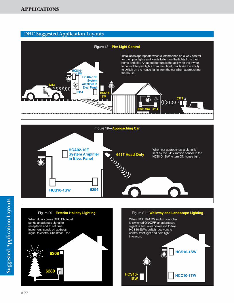
APPLICATIONSSu
gges
ted
Ap
pli
cati
onLa
you
ts
AP7
DHC Suggested Application Layouts
6314HCS10-1SW
6313
6314
6313
HCC1A- 1TW
HCS10- 1SW
HCA02-10E System
Amplifier in Elec. Panel
Figure 18—Pier Light Control
Installation appropriate when customer has no 3-way controlfor their pier lights and wants to turn on the lights from theirhome and pier. An added feature is the ability for the ownerto control the pier lights from their boat, much like the abilityto switch on the house lights from the car when approachingthe house.
6417 Head OnlyHCA02-10E System Amplifierin Elec. Panel
HCS10-1SW 6294
Figure 19—Approaching Car
When car approaches, a signal issent by the 6417 motion sensor to theHCS10-1SW to turn ON house light.
6308
6280
Figure 20—Exterior Holiday Lighting
When dusk comes DHC Photocellsends an address signal to receptacle and at set time increment, sends off address signal to control Christmas Tree.
HCC10-1TWHCS10- 1SW
HCS10-1SW
Figure 21—Walkway and Landscape Lighting
When HCC10-1TW switch controlleris switched ON/OFF, an addressedsignal is sent over power line to twoHCS10-SW’s switch receivers tocontrol front light and pole light in unison.

APPLICATIONS
AP8
DHC Suggested Application Layouts
Sugg
este
d A
pp
lica
tion
Layo
uts
HCS10- 1SW
HCC10- 1TW
HCA02-10E System Amplifier In ElectricPanel
HCS10- 1SW
Figure 22—Garage Lights
When HCC10-1TW switch controller is switchedON/OFF, an addressed signal is sent via powerline to HCS10-1SW switch receiver controlling thelight on the detached garage.
6314
6227
6313
Figure 24—Bug Zapper
Bug Zapper plugged into receptacle receiver 6227 can beturned ON/OFF by using a 6313 handheld remote controllerwhich sends addressed signal via "RF" to 6314-W plug-intransceiver. The 6314 sends addressed signal over power line to receptacle receiver.
REL
Sliding Gate
TDRL
6315
HCS10-1SW
HCS10-1SW
6417MOTIONSENSOR
6315
PHOTOCELL
HCS10-1SW
(TIME DELAYRELAY)
Figure 23—Driveway Lights and Gate
To open the driveway gate, the 6417 motion sensor senses the car’s approach and triggersthe 6315 Maintained Dry Contact Control to send ON command to driveway lights via HCS10-1SW switch receivers. The lights will turn ON for 15 minutes with time delay relay. During day-light, the photocell controller will “know” not to turn lights on. You can also control the slidinggate from inside the house using any DHC controller (not shown).

APPLICATIONSSu
gges
ted
Ap
pli
cati
onLa
you
ts
AP9
DHC Suggested Application Layouts
6314
HCM10-1SW
6313
Figure 25—Pool LightsOwner turns pool light ON and controls DIM/BRIGHTEN functionfrom handheld 6313. The 6313 sends addressed signal via “RF”to 6314-W which sends command to HCM10-1SW over thepower line.
6227
63136314 &/or HCC10-1TW
Figure 26—Homework Time —TV OffParents can control power to TV sets when it’s homework time.Plug TV into receiver receptacle 6227. Send signal to controlledreceptacle to turn ON or OFF using either the HCC10-1TWswitch controller or via handheld remote controller 6313 fromremote location.
6313 6314 &/or
HCC10-1TW
HCS10-1SW
Yard Light
Figure 27—Security LightingHomeowner can control security lights controlled by HCS10-1SW receiver from remotelocation either via 6313 hand held remote controller and 6314-W remote transceivercombination or with an HCC10-1TW switch controller installed inside the house.
63136314
6337
Figure 28—Home Entertainment System
Homeowner can operate TV, movie screen, turn ON/OFF the stereo from the comfort ofthe easy chair by sending addressed signal using handheld remote controller 6313 via “RF” to 6314-W remote transceiver. The 6314-W sends signal via power line to6337 receiver. The 6337 then lowers or raises movie screen, turns ON/OFF TV and/orstereo.

APPLICATIONS
AP10
DHC Suggested Application Layouts
Sugg
este
d A
pp
lica
tion
Layo
uts
6227
HCC10-1TW
Figure 29—Garage Door Lock
Homeowner can control power to garage door motor to ensure it can’t be opened whileaway on vacation by sending OFF addressed signal from HCC10-1TW switch controllerto the 6227 receptacle receiver that garage motor is connected to.
HCS10-1SWWaterHeater
HCC10-1TW30A
Contactor
Figure 30—Control Water Heater
Homeowner can program water heater to turn ON or OFF at set time each day. HCC10-1TWswitch controller sends addressed signal to HCS10-1SW switch receiver via power line, toactivate or deactivate 30A contactor to operate heating coils in water heater.
VentsHCS10-1SW
6312
Figure 31—Control Attic Fan
Homeowner can program fan in attic to turn ON/OFF at set times using 6312 Wall-mountedprogrammer. The 6312 sends addressed signal to HCS10-1SW switch receiver via powerline to control attic fan motor.
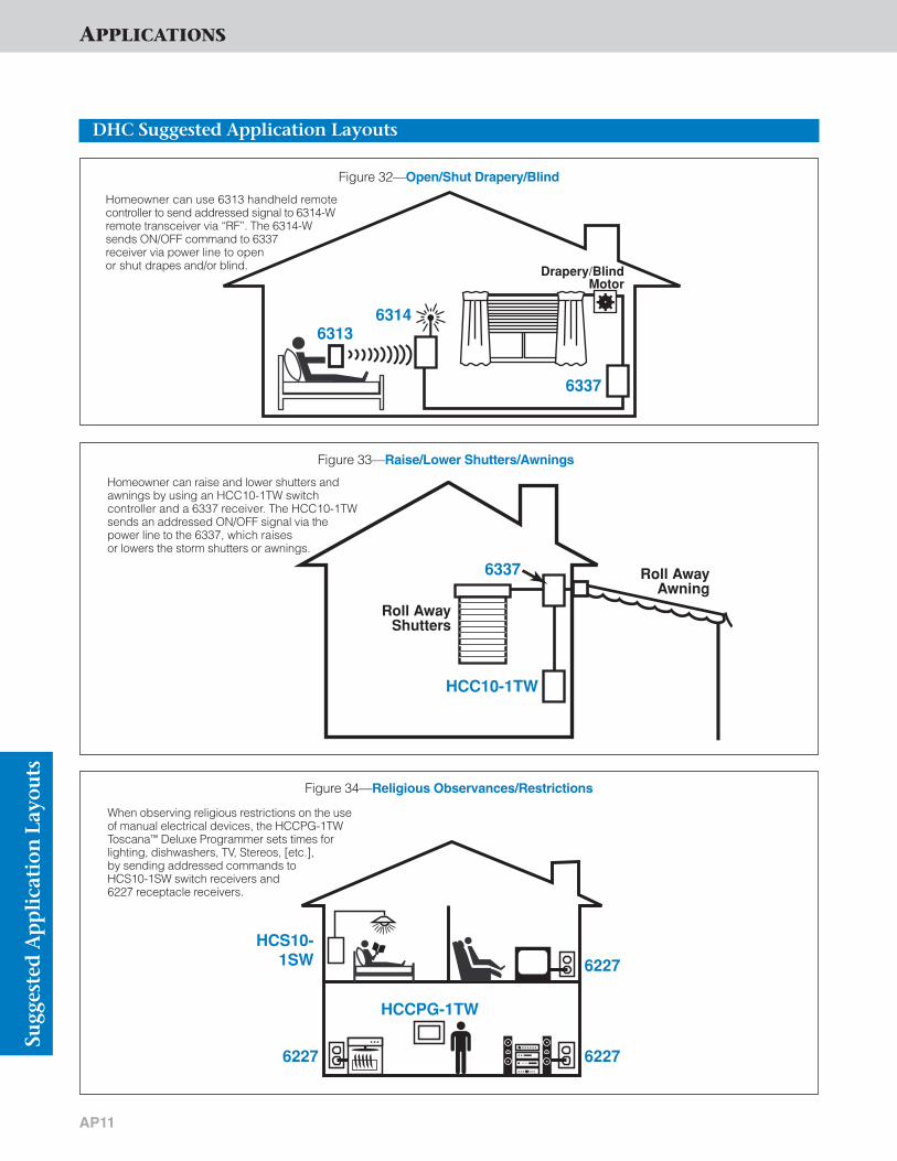
AP11
63136314
6337
Drapery/Blind Motor
Figure 32—Open/Shut Drapery/Blind
Homeowner can use 6313 handheld remotecontroller to send addressed signal to 6314-Wremote transceiver via “RF”. The 6314-Wsends ON/OFF command to 6337 receiver via power line to open or shut drapes and/or blind.
HCC10-1TW
6337
Roll Away Shutters
Roll Away Awning
Figure 33—Raise/Lower Shutters/Awnings
Homeowner can raise and lower shutters andawnings by using an HCC10-1TW switch controller and a 6337 receiver. The HCC10-1TWsends an addressed ON/OFF signal via thepower line to the 6337, which raises or lowers the storm shutters or awnings.
6227
62276227
HCS10- 1SW
HCCPG-1TW
Figure 34—Religious Observances/Restrictions
When observing religious restrictions on the useof manual electrical devices, the HCCPG-1TWToscana™ Deluxe Programmer sets times forlighting, dishwashers, TV, Stereos, [etc.], by sending addressed commands to HCS10-1SW switch receivers and 6227 receptacle receivers.
APPLICATIONS
DHC Suggested Application Layouts
Sugg
este
d A
pp
lica
tion
Layo
uts

AP12
HCM10- 1SW HCS10-
1SW6227
HCC1A-1TW
HCS10-1SW
HCC1A-1TW
Figure 35—All Lights On “Panic Button” Feature
Many types of lighting loads can be connected to DHC Switches & Receptacles for this safety andsecurity application. Homeowners can retire tobed at night and switch OFF lighting throughoutthe home utilizing one switch controller. If a noise is heard during the night, an HCC1A-1TW switch controller installed at bedside provides an added “ALL LIGHTS ON”“Panic Button” feature.
HCC10- 1TW
HCS10- 1SW
HCCPG-1TW
Figure 36—Control of Front Door and Outside Soffit Lighting from Bedroom
Front door and outside soffit lighting can be switchedON/OFF by utilizing an HCCPG-1TW Toscana™ DeluxeProgrammer at set times for security. The same lighting can be manually operated by the HCS10-1SW switch receiver installed at the front door or by an HCC10-1TW switch controller installed in master bedroom.
APPLICATIONS
DHC Suggested Application Layouts
Sugg
este
d A
pp
lica
tion
Layo
uts
SAFETY and SECURITY


TECHNICAL SECTION

TECHNICAL SECTIONTe
chn
ical
Sec
tion
T1
Wiring Diagrams (Receivers)
HCM06 & HCM10-1SW/1DWSingle-Pole Application—Incandescent
HCM06 & HCM10-1SW/1DW Single-Pole Application—Magnetic Low Voltage
LINE (Hot)
Blue
LOAD
Yellow Lead
Black
NEUTRAL
Cap withWire Connector
WhiteLOAD
White
DHC Scene Capable Receiver
GreenGround
LOAD
LINE (Hot) LOAD
Blue
Yellow Lead
Black
NEUTRAL
Cap withWire Connector
White
DHC Scene Capable Receiver
GreenGround
LOAD
LINE (Hot) LOAD
Blue
Yellow Lead
Black
NEUTRAL
Cap withWire Connector
White
GreenGround
DHC Scene Capable Receiver
Application without Neutral Wiring
Application with Neutral Wiring (preferred)
Hot (Black)
Neutral (White)
Load
HCM06/HCM10-1SW, 1DW
Blue Blue
Yellow Yellow
GreenGround
GreenGround
Black
White
Black
White Line
120VAC, 60Hz
RemoteMS00R-10//
Hot (Black)
Neutral (White)
BlackBlack
White
Blue
Line 120VAC, 60Hz
White
Load
GreenGround
HCM06 & HCM10-1SW/1DW Multi-Location Application
Load
Hot (Black)
Neutral (White)
Blue
Green Ground(10, 1A and
1D Only)
Black Black
White
Line 120VAC, 60Hz
ControllerHCCxx
Black
White
WhiteGreen Ground
HCM06/HCM10/HCS08-1TW Single-Pole Application—Incandescent
HCM06/HCM10/HCS08-1TW Multi Location—Incandescent
Note: Always follow closely the wiring diagrams andinstructions included with each Leviton DHC device.

TECHNICAL SECTION
T2
Wiring Diagrams (Receivers)
Tech
nic
al S
ecti
on
Hot (Black)
Neutral (White)
Load
Blue Blue
Yellow Yellow
GreenGround
GreenGround
Black
White
Black
Line 120VAC, 60Hz
Multi-RemoteMS00R-10//
}
(OR PRIMARY SIDE OF
MAGNETIC LOW-VOLTAGE
TRANSFORMER)
HCM06/HCM10-1SW & 1DW
White
Hot (Black)
Neutral (White)
Load
Blue BlueBlue
Yellow Yellow Yellow
GreenGround
GreenGround
GreenGround
Black
White
Black
Line 120VAC, 60Hz
Multi-RemoteMS00R-10
Multi-RemoteMS00R-10/ / / /
}
(OR PRIMARY SIDE OF
MAGNETIC LOW-VOLTAGE
TRANSFORMER)
HCM06/HCM10-1SW & 1DW
White
HCM06/HCM10/HCS08-1TW Single Magnetic Low-Voltage Application
HCM06/HCM10/HCS08-1TW Multi-LocationMagnetic Low-Voltage Application
Load
Hot (Black)
Neutral (White)
Black
Black
White
Blue
Line 120VAC, 60Hz
WhiteGreenGround
Hot (Black)
Neutral (White)
HCM06/HCM10/HCS08-1TW
BlueBlack Black
White
Line 120VAC, 60Hz
Controller HCCxx
White
Load
Black
WhiteGreen Ground(10, 1A and 1D Only)
GreenGround
MS00R-10 Multi-Location Control Application
MS00R-10 Multi-Location Control Application
Hot (Black)
Neutral (White)
Load
HCS10-1SW
Blue Blue
Yellow Yellow
GreenGround
GreenGround
Black
White
Black
White Line
120VAC, 60Hz
RemoteMS00R-10//
HCS10-1SW Multi-Location Application
HCS10-1SW Single-Pole Application
Hot (Black)
Neutral (White)
BlackBlack
White
Blue
Line 120VAC, 60Hz
White
HCS10-1SW
Load
GreenGround
Yellow Lead
Cap withWire
Connector
Note: Always follow closely the wiring diagrams andinstructions included with each Leviton DHC device.

TECHNICAL SECTIONTe
chn
ical
Sec
tion
T3
Wiring Diagrams (Receivers)
120V
CONTROL
TO LINE
NEUTRAL
6383-WI 6294
LOAD
LOAD
LINE
CONTROL
LINE
NEUTRAL
LOAD
6291-WI Single-Pole (One Location) Switch
6383-WI Multi-Location Incandescent Switch
120V
CONTROL
TO LINE
NEUTRAL
6293 6294
LOAD
LOAD
NEUTRAL
LINE
CONTROL
WHITE (NEUTRAL)
LINE
WHITE
TO LINE
BLUE TO LOAD
6294
6293
RED TO CONTROL
BLACK TO LINE
LOAD
6294
TO LINE
TO CONTROL
TO CONTROL
WHITE (NEUTRAL)
LOAD
YELLOW BLUE
LINE-1 (BLACK)
LINE-2 (RED)
WHITE LEAD
BLACK LEAD
A
EM
I
1
513
9
CONTROLLED
TO NEUTRAL
TO LINE6293-WI 3-Way (Multi-Location) Switch
6294 3 & 4-Way (Multi-Location) Remote Switch
6371-I Double-Pole Wall Switch
6227 Split Duplex Wall Receptacle Module
WHITE LEAD
BLACK LEAD
TO NEUTRALA
EM
I
1
513
9
BLUE LEAD
Feed- through to other receptacles downstream
GREEN LEAD TO GROUND
TO LINE
6280 Duplex Wall Receptacle Module
WHITE LEAD
BLACK LEAD
TO NEUTRAL
TO LINE
A
EM
I
1
513
9
GREEN LEADTO GROUND
6296/6298 Single Wall Receptacle Module
Note: Always follow closely the wiring diagrams andinstructions included with each Leviton DHC device.
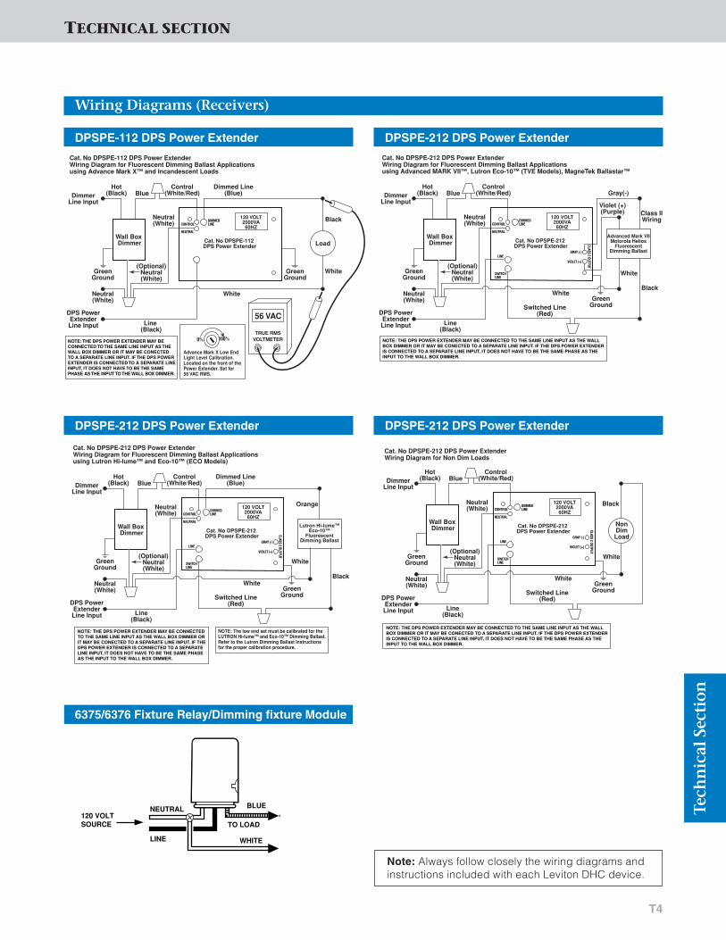
TECHNICAL SECTION
T4
Wiring Diagrams (Receivers)
Tech
nic
al S
ecti
on
Load
GreenGround
Neutral(White)
White
White
BlackNeutral(White)
Hot(Black)
Line (Black)
Control(White/Red)
Dimmed Line(Blue)Blue
(Optional)Neutral(White)
DimmerLine Input
DPS PowerExtenderLine Input
Wall Box Dimmer
GreenGround
Cat. No DPSPE-112 DPS Power ExtenderWiring Diagram for Fluorescent Dimming Ballast Applicationsusing Advance Mark X™ and Incandescent Loads
Cat. No DPSPE-112 DPS Power Extender
56 VAC
120 VOLT2000VA60HZ
TRUE RMSVOLTMETER
DIMMEDLINE
NOTE: THE DPS POWER EXTENDER MAY BE CONNECTED TO THE SAME LINE INPUT AS THE WALL BOX DIMMER OR IT MAY BE CONECTED TO A SEPARATE LINE INPUT. IF THE DPS POWER EXTENDER IS CONNECTED TO A SEPARATE LINE INPUT, IT DOES NOT HAVE TO BE THE SAME PHASE AS THE INPUT TO THE WALL BOX DIMMER.
CONTROL
NEUTRAL
0% 100%
Advance Mark X Low End Light Level Calibration. Located on the front of the Power Extender. Set for 56 VAC RMS.
DPSPE-112 DPS Power Extender
GreenGround
Neutral(White)
White
White
Black
OrangeNeutral(White)
Hot(Black)
Line(Black)
Switched Line(Red)
Control(White/Red)
Dimmed Line(Blue)Blue
(Optional)Neutral(White)
DimmerLine Input
DPS PowerExtenderLine Input
Wall Box Dimmer
GreenGround
Cat. No DPSPE-212 DPS Power ExtenderWiring Diagram for Fluorescent Dimming Ballast Applicationsusing Lutron Hi-lume™ and Eco-10™ (ECO Models)
Cat. No DPSPE-212 DPS Power Extender
120 VOLT2000VA60HZ
Lutron Hi-lume™Eco-10™
FluorescentDimming Ballast
DIMMEDLINE
NOTE: THE DPS POWER EXTENDER MAY BE CONNECTED TO THE SAME LINE INPUT AS THE WALL BOX DIMMER ORIT MAY BE CONECTED TO A SEPARATE LINE INPUT. IF THE DPS POWER EXTENDER IS CONNECTED TO A SEPARATE LINE INPUT, IT DOES NOT HAVE TO BE THE SAME PHASE AS THE INPUT TO THE WALL BOX DIMMER.
CONTROL
NEUTRAL
LINEGRAY (-)
VIOLET (+)
CLASS 2 OUTPUT
SWITCHLINE
NOTE: The low end set must be calibrated for the LUTRON Hi-lume™ and Eco-10™ Dimming Ballast.Refer to the Lutron Dimming Ballast Instructions for the proper calibration procedure.
DPSPE-212 DPS Power Extender
NEUTRAL
LINE
120 VOLT SOURCE
WHITE
TO LOAD
BLUE
6375/6376 Fixture Relay/Dimming fixture Module
DPSPE-212 DPS Power Extender
GreenGround
Neutral(White)
White
White
Black
Class IIWiringNeutral
(White)
Hot(Black)
Line(Black)
Switched Line(Red)
Control(White/Red)
Violet (+)(Purple)
Gray(-)Blue
(Optional)Neutral(White)
DimmerLine Input
DPS PowerExtenderLine Input
Wall Box Dimmer
GreenGround
Cat. No DPSPE-212 DPS Power ExtenderWiring Diagram for Fluorescent Dimming Ballast Applicationsusing Advanced MARK VII™, Lutron Eco-10™ (TVE Models), MagneTek Ballastar™
Cat. No DPSPE-212 DPS Power Extender
120 VOLT2000VA60HZ
Advanced Mark VIIMotorola Helios
FluorescentDimming Ballast
DIMMEDLINECONTROL
NEUTRAL
LINEGRAY (-)
VIOLET (+)
CLASS 2 OUTPUT
SWITCHLINE
NOTE: THE DPS POWER EXTENDER MAY BE CONNECTED TO THE SAME LINE INPUT AS THE WALL BOX DIMMER OR IT MAY BE CONECTED TO A SEPARATE LINE INPUT. IF THE DPS POWER EXTENDER IS CONNECTED TO A SEPARATE LINE INPUT, IT DOES NOT HAVE TO BE THE SAME PHASE AS THE INPUT TO THE WALL BOX DIMMER.
DPSPE-212 DPS Power Extender
GreenGround
Neutral(White)
White
White
BlackNeutral(White)
Hot(Black)
Line(Black)
Switched Line(Red)
Control(White/Red)Blue
(Optional)Neutral(White)
DimmerLine Input
DPS PowerExtenderLine Input
Wall Box Dimmer
GreenGround
Cat. No DPSPE-212 DPS Power ExtenderWiring Diagram for Non Dim Loads
Cat. No DPSPE-212 DPS Power Extender
120 VOLT2000VA60HZ
DIMMEDLINECONTROL
NEUTRAL
LINEGRAY (-)
VIOLET (+)
CLASS 2 OUTPUT
SWITCHLINE
NOTE: THE DPS POWER EXTENDER MAY BE CONNECTED TO THE SAME LINE INPUT AS THE WALL BOX DIMMER OR IT MAY BE CONECTED TO A SEPARATE LINE INPUT. IF THE DPS POWER EXTENDER IS CONNECTED TO A SEPARATE LINE INPUT, IT DOES NOT HAVE TO BE THE SAME PHASE AS THE INPUT TO THE WALL BOX DIMMER.
NonDimLoad
Note: Always follow closely the wiring diagrams andinstructions included with each Leviton DHC device.
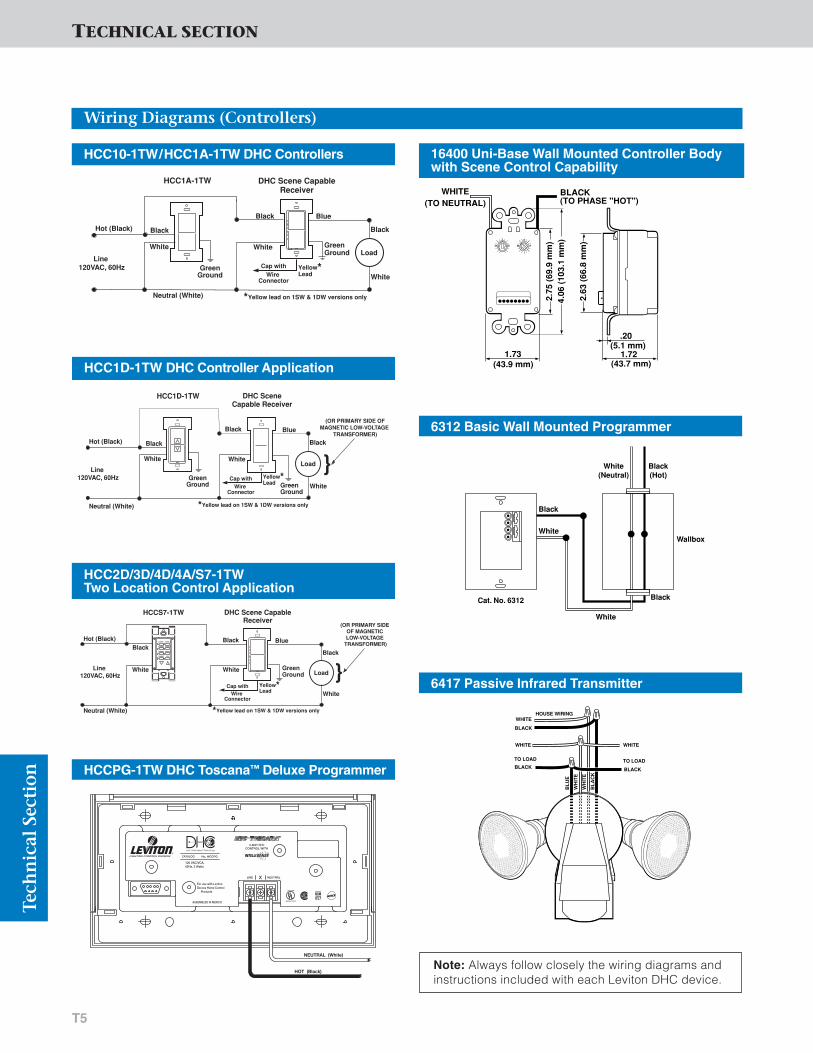
TECHNICAL SECTIONTe
chn
ical
Sec
tion
T5
Wiring Diagrams (Controllers)
HCC1A-1TW
Hot (Black)
Neutral (White)
Load
BlueBlack
GreenGround
Black
White
Black
Line 120VAC, 60Hz
DHC Scene Capable Receiver
GreenGround
White
Yellow* Lead
*Yellow lead on 1SW & 1DW versions only
Cap withWire
Connector
White
HCC10-1TW/HCC1A-1TW DHC Controllers
HCC1D-1TW DHC Controller Application
Hot (Black)
Neutral (White)
Load
HCC1D-1TW
Blue
GreenGround Green
Ground
Black
White
Black
Line 120VAC, 60Hz
DHC Scene Capable Receiver
(OR PRIMARY SIDE OFMAGNETIC LOW-VOLTAGE
TRANSFORMER)
}WhiteWhite
Black
Cap withWire
Connector
Yellow* Lead
*Yellow lead on 1SW & 1DW versions only
Hot (Black)
Neutral (White)
Load
DHC Scene Capable Receiver
BlueBlack
Black
White
White White
Black
Line 120VAC, 60Hz
HCCS7-1TW
GreenGround
(OR PRIMARY SIDE OF MAGNETIC LOW-VOLTAGE
TRANSFORMER)
}Cap with
Wire Connector
Yellow* Lead
*Yellow lead on 1SW & 1DW versions only
HCC2D/3D/4D/4A/S7-1TW Two Location Control Application
2.63
(66
.8 m
m)
2.75
(69
.9 m
m)
4.06
(10
3.1
mm
)
1.73(43.9 mm)
.20(5.1 mm)
(43.7 mm)1.72
WHITE(TO NEUTRAL)
BLACK(TO PHASE "HOT")
1
513
A
EM
16400 Uni-Base Wall Mounted Controller Bodywith Scene Control Capability
Black
Black
WallboxWhite
White
White(Neutral)
Black(Hot)
Cat. No. 6312
6312 Basic Wall Mounted Programmer
HOUSE WIRINGWHITE
BLACK
WHITE WHITE
BLACK
BL
UE
WH
ITE
WH
ITE
BL
AC
K
BLACKTO LOADTO LOAD
6417 Passive Infrared Transmitter
HCCPG-1TW DHC Toscana™ Deluxe Programmer
NEUTRAL (White)
HOT (Black)
CATALOG No. HCCPG
120 VAC/VCA,60Hz, 3 Watts
For use with LevitonDecora Home Control Products
ASSEMBLED IN MEXICO
XLINE NEUTRAL
CONTROL WITH2-WAY DHC
Listed 898F
Appliance Control
®
Note: Always follow closely the wiring diagrams andinstructions included with each Leviton DHC device.

TECHNICAL SECTION
T6
Wiring Diagrams (Controllers)
Tech
nic
al S
ecti
on
Black
Black
Wallbox
White
White
DARK
HOUSE
ON
1 2 3 4OFF
UNIT
DELAY
DUSK
Cat. No. 6308
White(Neutral)
Black(Hot)
A
I
• •
• •
O C• •• •
M EK G
1
9
• •
• •
15 3• •• •
13 511 7
0
4
• •
• •
7 1• •• •6 25 3
6308 Photocell Transmitter
6315 Maintained Dry Contact Transmitter
.937
2.62
5 (
66.6
7mm
)
2.75
0 (
69.8
5mm
)
4.06
2 (
103.
18m
m)
(33.32mm)
1.750(44.45mm)
.437(11.10mm)
(47.62mm)1.875
BLACK
WHITE
A
EM
I
1
513
9
A
EM
I
1
513
9
BLACK(TO LINE)
WHITE(NEUTRAL)
120 V.A.C.
YELLOW
BROWN
RED (COMMON +)
(COMMON –)
BLUE
ORANGE
GRAY
6316 Momentary Dry Contact Transmitter
.937
2.62
5 (
66.6
7mm
)
2.75
0 (
69.8
5mm
)
4.06
2 (
103.
18m
m)
(33.32mm)
1.750(44.45mm)
.437(11.10mm)
(47.62mm)1.875
BLACK
WHITE
A
EM
I
1
513
9
A
EM
I
1
513
9
BLACK(TO LINE)
WHITE(NEUTRAL)
120 V.A.C.
YELLOW
BROWN
RED (COMMON +)
(COMMON –)
BLUE
ORANGE
GRAY
Note: Always follow closely the wiring diagrams andinstructions included with each Leviton DHC device.

TECHNICAL SECTIONTe
chn
ical
Sec
tion
T7
Wiring Diagrams (Network Integity Products)
NLINE
A BLINE
HCA02-10E
15A DOUBLE-POLEBREAKER, OR TWO15A S.P. BREAKERSEQUIPPED WITHHANDLE TIE
WHITELEAD
BLACKLEAD
REDLEAD
RED–Phase ABLACK–Phase BWHITE–Neutral
AB AB AB
HCA02-10E
PANEL1
PANEL2
MAINPANEL
BLACK
RED RED
BLACK
HCA02-10E
N
WHITE WHITE
For larger installations where multiple Cat. No. HCA02-10E SystemAmplifiers are used, they must be connected consistently:
HCA02-10E System Amplifier
N Ø1 Ø2
6201
15A BREAKERSEQUIPPED WITHHANDLE TIE
WHITELEAD
Ø3
BLACK 1BLACK 2
RED
If multiple 6201 System Amplifiers are used in a 3-Phase system, all three phases must be connected on all Repeaters.If single-phase sub panels are used, only 2 phases of the 3-phase system can be used. System Amplifiers should beplaced on the sub panels where the 2 phases being usedexist. Note that this is not a recommended practice for newconstruction where DHC products will be installed. Levitonstrongly recommends using 3-phase sub panels on all circuits feeding DHC products.
NLINE
A BLINE
6201
BLK 2 CAPPED OFF
15A DOUBLE-POLEBREAKER, OR TWO15A S.P. BREAKERSEQUIPPED WITHHANDLE TIE
WHITELEAD
RED LEAD
BLACKLEAD
RED–Phase ABLK 1–Phase BBLK 2–Capped
AB AB AB
6201
PANEL1
PANEL2
MAINPANEL
6201
BLK 2 CAPPED OFF
BLK 1
RED RED
BLK 1
BLK 2 CAPPED OFF
For larger installations where multiple Cat. No. 6201 System Amplifiersare used, they must be connected consistently:
6201 System Amplifier
51120-1
LINE A
LINE B
NEUTRAL
USE #10STRANDED 18"
LEADS15A 2-POLECIRCUIT BREAKER
51120-1/51120-3R/51120-PTC Panel Mounted Surge Protective Device (SPD)
Note: Always follow closely the wiring diagrams andinstructions included with each Leviton DHC device.

TECHNICAL SECTION
T8
Wiring Diagrams (Ancillary DHC Devices)
Tech
nic
al S
ecti
on
Breaker panel
N
N
POWER
METER
L1
L2
L3
L1 L 2 L3
6284 Multi-Phase Blocking Coupler
6287 Noise Block
6289 In-Line Noise Reducer
6285 Signal Attenuator
6285
BLACK LEADS
LINE 2LINE 1N
WHITE LEADS
120V LOAD
CONTROLLER
15ACIRCUITBREAKER
6287
NEUTRAL
LOAD
LINE
WHITE
DHCMODULE
LINE
BLACK
BLUE
GREEN
LOAD
WHITE
1.16
8(2
9.66
mm
)
2.600 (66.04mm)
MODULE
TO
LOAD
120 V 6289
Note: Always follow closely the wiring diagrams andinstructions included with each Leviton DHC device.

TECHNICAL SECTIONTe
chn
ical
Sec
tion
T9
Dimensional Drawings (Receivers)
MS00R-10 Multi-Remote Switch
HCM06/10-1SW Dimming Switch with Scene Control
2.38 (60.5 mm)
1.38 (35.2 mm)
1.73 (43.9 mm)
4.13
(10
4.9
mm
)
2.68
(67.
6 m
m)
(35.2 mm)1.38
2.68
(42.5 mm)1.67
(60.3mm)2.38
4.11
3.28
1
(67.
6 m
m)
(104
.4 m
m)
(83.
3 m
m)
HCM06/10-1DW DHC Dimmer-Lighted
HCM06/10-1TW DHC Dimmer 2-Way Lighted
(35.2 mm)1.38
2.68
(42.5 mm)1.67
(60.3 mm)2.38
4.11
3.28
1
(67.
6 m
m)
(83.
3 m
m)
(104
.4 m
m)
HCS08-1TW DHC Scene Capable Switch
HCS10-1SW Switch with Scene Control
2.38 (60.5 mm)
1.38 (35.2 mm)
1.73 (43.9 mm)
4.13
(10
4.9
mm
)
2.68
(67.
6 m
m)
2.38 (60.5 mm)
1.38 (35.2 mm)
1.73 (43.9 mm)
4.13
(10
4.9
mm
)
2.68
(67.
6 m
m)
(35.2 mm)1.38
2.68
(42.5 mm)1.67
(60.3 mm)2.38
4.11
3.28
1
(67.
6 m
m)
(83.
3 m
m)
(104
.4 m
m)
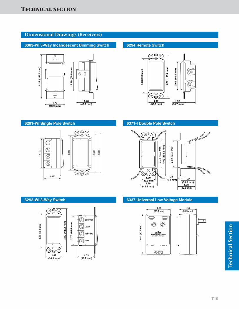
TECHNICAL SECTION
T10
Dimensional Drawings (Receivers)
Tech
nic
al S
ecti
on
6383-WI 3-Way Incandescent Dimming Switch
1.73(43.9 mm)
2.70
(68
.6 m
m)
4.10
(10
4.1
mm
)
1.78(45.2 mm)
6291-WI Single Pole Switch
6293-WI 3-Way Switch
1.525
3.64
2
3.81
2
3.21
6
2.70
0
1.53(38.9 mm)
2.70
(68
.6 m
m)
CONTROL
LOAD
NEUTRAL
LINE
4.06
(10
3.1
mm
)
3.28
(83
.3 m
m)
1.42(36.0 mm)
6294 Remote Switch
1.52(38.7 mm)
2.62
(66
.5 m
m)
4.06
(10
3.1
mm
)
3.28
(83
.3 m
m)
1.42(36.0 mm)
6371-I Double Pole Switch
2.62
(66
.5 m
m)
2.75
(69
.9 m
m)
4.09
(10
3.9
mm
)
1.30 (33.0 mm)
1.70 (43.2 mm)
.25(6.4 mm) 1.40
(35.6 mm)1.69
(42.9 mm)
6337 Universal Low Voltage Module
1.55 (39.5 mm)
3.57
(90
.7 m
m)
2.20 (55.9 mm)
1
5
9
13
A
EM
®
®
TEST UNIT OFF
UNIVERSAL MODULE
UNIT CODE HOUSE CODE
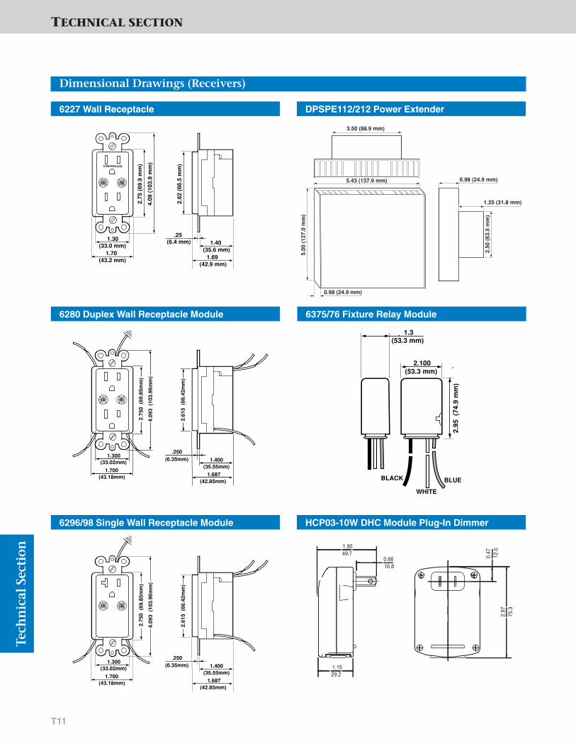
Tech
nic
al S
ecti
on
T11
Dimensional Drawings (Receivers)
6227 Wall Receptacle
1.30
2.62
(66
.5 m
m)
2.75
(69
.9 m
m)
4.09
(10
3.9
mm
)
(33.0 mm)1.70
(43.2 mm)
.25 (6.4 mm) 1.40
(35.6 mm)
A
EM
I
1
513
9
1.69 (42.9 mm)
CONTROLLED
6280 Duplex Wall Receptacle Module
1.300
2.61
5 (
66.4
2mm
)
2.75
0 (
69.8
5mm
)
4.09
3 (
103.
96m
m)
(33.02mm)
1.700(43.18mm)
.250(6.35mm)
(35.55mm)1.400
A
EM
I
1
513
9
(42.85mm)1.687
6296/98 Single Wall Receptacle Module
1.300
2.61
5 (
66.4
2mm
)
2.75
0 (
69.8
5mm
)
4.09
3 (
103.
96m
m)
(33.02mm)
1.700(43.18mm)
.250(6.35mm)
(35.55mm)1.400
A
EM
I
1
513
9
(42.85mm)1.687
6375/76 Fixture Relay Module
DPSPE112/212 Power Extender
2.95
(74
.9 m
m)
2.100(53.3 mm)
BLACK
WHITE
BLUE
1.3(53.3 mm)
HCP03-10W DHC Module Plug-In Dimmer
49.71.95
16.80.66
29.21.15
12.0
0.47
75.3
2.97
TECHNICAL SECTION
3.50 (88.9 mm)
5.43 (137.9 mm)
5.00
(12
7.0
mm
)
0.98 (24.9 mm)
1.25 (31.8 mm)
2.50
(63
.5 m
m)
0.98 (24.9 mm)
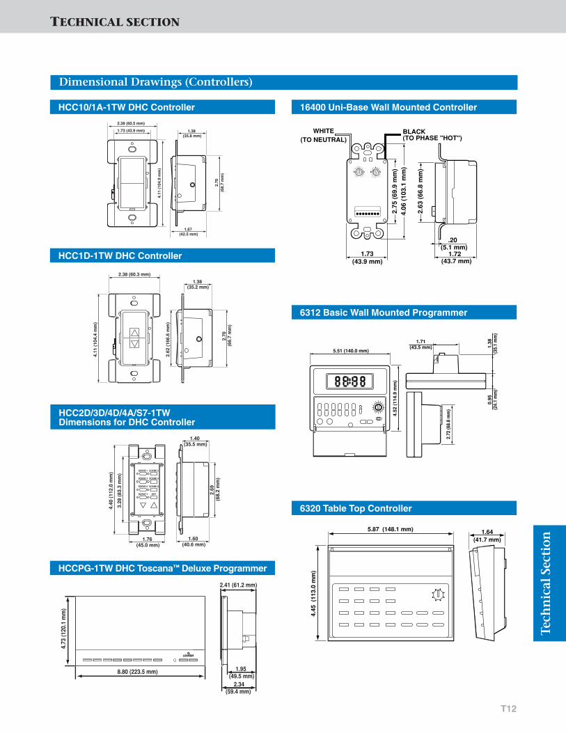
T12
Dimensional Drawings (Controllers)
Tech
nic
al S
ecti
on
HCC10/1A-1TW DHC Controller
2.70
(68.
7 m
m)
2.38 (60.5 mm)
1.38 (35.8 mm)
1.73 (43.9 mm)
4.11
(10
4.9
mm
)
1.67 (42.5 mm)
HCC1D-1TW DHC Controller
2.38 (60.3 mm)
2.62
(16
6.6
mm
)
2.70
(66
.7 m
m)
4.11
(10
4.4
mm
)
1.38 (35.2 mm)
HCC2D/3D/4D/4A/S7-1TW Dimensions for DHC Controller
1.76 (45.0 mm)
2.69
(6
8.2
mm
)
3.28
(83
.3 m
m)
4.40
(11
2.0
mm
)
1.40 (35.5 mm)
1.60 (40.6 mm)
SCENE 1
SCENE 3
SCENE 2
SCENE 4
SCENE 5 SCENE 6
SCENE 7 OFF
8.80 (223.5 mm)
2.34 (59.4 mm)
1.95 (49.5 mm)
4.73
(120
.1 m
m)
2.41 (61.2 mm)
HCCPG-1TW DHC Toscana™ Deluxe Programmer
16400 Uni-Base Wall Mounted Controller
2.63
(66
.8 m
m)
2.75
(69
.9 m
m)
4.06
(10
3.1
mm
)
1.73(43.9 mm)
.20(5.1 mm)
(43.7 mm)1.72
WHITE(TO NEUTRAL)
BLACK(TO PHASE "HOT")
1
513
A
EM
6312 Basic Wall Mounted Programmer
1.71(43.5 mm) 1.
38(3
5.1
mm
)0.
95(2
4.1
mm
)
5.51 (140.0 mm)
4.52
(11
4.9
mm
)
2.72
(68.
8 m
m)
6320 Table Top Controller
1.64(41.7 mm)
5.87 (148.1 mm)
4.45
(11
3.0
mm
)
TECHNICAL SECTION

Tech
nic
al S
ecti
on
T13
TECHNICAL SECTION
Dimensional Drawings (Controllers)
6314-W Remote Transceiver
6313 Hand-Held Controller
6308 Photocell Transmitter
6325 Telephone Transponder
2.80(71.1 mm)
4.53
(11
5.1
mm
)
0.81(20.7 mm)
1.26(32.1 mm)
®
Transceiver Module
HOUSE
ON/OFF
A
E
I
M
O C
GK
2.75 (70.0 mm)
4.50
(11
4.3
mm
)
3.28 (83.31 mm)1.18 (45.9 mm)
4.48 (113.9 mm)0.61(15.4 mm)
BACK-WIRE HOLES
CODEDIALS
6.97 (177.0 mm)
5.98 (51.9 mm)
4.61
(11
7.1
mm
)1.
12
(28.
4 m
m)
6315/16 Maintained Dry Contact Transmitter
2.63
(66
.8 m
m)
2.75
(69
.8 m
m)
4.06
(10
3.1
mm
)
.94 (33.3 mm)
1.75 (44.5 mm)
.44(11.2 mm)
1.88 (47.8 mm)
BLACK
WHITE
A
EM
I
1
513
9

T14
TECHNICAL SECTION
Dimensional Drawings (Network Integity Products)
Tech
nic
al S
ecti
on
HCA02-10E System Amplifier
1.644.49 (113.9 mm)
2.79
(70
.9 m
m)
41.7 mm4.77 (121.2 mm)
3.08
(78
.1 m
m)
6201 System Amplifier
1.644.49 (114.0 mm)
2.79
(70
.9 m
m)
(41.7 mm)4.77 (121.2 mm)
3.08
(78
.2 m
m)
PILOT LIGHT
51120-1/3
6.00 (152.4mm)
6.00
RE
F. (
152.
4mm
)
7.00
(17
7.8m
m)
6.00
(15
2.4m
m)
7.00 (177.8mm)4.06
(103.12mm)
51120-3R Panel Mounted Surge Protectection Device
4.00 (101.6 mm)
4.45 (113.03 mm)
6.00 (152.4 mm)
2.25 (57.1 mm)
6.50 (165.1 mm)
Ø 0
.281
(7.1
mm
)
5.88
(14
9.3
mm
)1.
06 (
26.9
mm
)
CL
51120-PTC Multimedia Surge Suppression Panel
LINE 1 LINE 2
FAULT
IN OUTTELEPHONE PROTECTION
IN OUT CATV / SATELLITE PROTECTION
Surge Protection
YellowGreen
White
Black
18 AWG WIRES12 AWG WIRES
Orange
Blue18
.00"
8.00
"2
1/2"
4 1/2"6 1/8"

T15
TECHNICAL SECTION
Dimensional Drawings (Ancillary DHC Devices and Product Testing)
6287 Noise Block
1.85 (46.9 mm)
1.58
(40
.1 m
m)
BLACK LOAD
BLACK HOT L
WHITE NEUTRAL
R
5 AMP BLOCKCAT. NO. 6287
UL® LISTED898F APPLIANCE CONTROL
6287
6288 Plug-In Noise Filter
1.43(36.2 mm)
2.92
(74
.2 m
m)
6289 In-Line Noise Reducer
1.17(29.7 mm)
2.60
(66
.0 m
m)
Tech
nic
al S
ecti
on

G-5868/B2-25M rs
NOTES

Leviton’s Limited Two-Year Warranty
Leviton Manufacturing Co., Inc., Little Neck, NY 11362-2591
Decora Home Controls are intended for residential applications only. Use in commercial andindustrial applications will void the Warranty. This warranty gives you specific legal rights, andyou may also have other rights which vary from state to state. LEVITON warrants to the originalpurchaser that this product is free of defects in materials and workmanship for two years fromthe purchase date. Leviton will correct such defects by repair or replacement, at its option, if theproduct is returned, prepaid, with proof of purchase to: Leviton Manufacturing Co., Inc., Attn:Quality Assurance Dept., 59-25 Little Neck Parkway, Little Neck NY 11362-2591. This Warrantydoes not cover labor for removal or reinstallation of the product and is void on any product im-properly installed, overloaded, abused or altered in any manner. Leviton limits the duration ofany implied warranty of merchantability to one year and excludes incidental or consequentialdamages for breach of any warranty on this product. Some states do not allow limitations onhow long an implied warranty lasts, or the exclusion or limitation of incidental or consequentialdamages, so the above exclusions or limitations may not apply to you. If LEVITON agrees, inwriting, to assist in residential applications, a fee for services will be charged.
© Copyright 2002 Leviton Manufacturing Co., Inc. All rights reserved

Leviton Manufacturing Co., Inc. 59-25 Little Neck Parkway, Little Neck, NY 11362-2591Telephone: 1-800-323-8920 • FAX: 1-800-832-9538Tech Line (8:30AM-7:30PM E.S.T. Monday-Friday): 1-800-824-3005
Leviton Manufacturing of Canada, Ltd.165 Hymus Boulevard, Pointe Claire, Quebec H9R 1E9Telephone: 1-800-469-7890 • FAX: 1-800-563-1853
Leviton S.A. de C.V.General Arista 54-A Col. Argentina, Mexico D.F., C.P. 11270Telephone: 011-525-386-1131, 011-525-386-2052 • FAX: 011-525-386-1797
Visit Leviton’s Web site at : www.leviton.com
© Copyright 2002 Leviton Manufacturing Co., Inc. All rights reserved. G-5868/B2-25M rs