Embed Size (px)
Citation preview

A division of the WIKA Group
www.ksr-kuebler.com
LEVELMEASUREMENT
FOR NUCLEAR POWER PLANTS
2
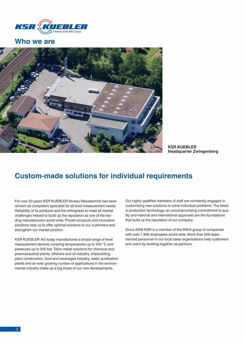
KSR KUEBLERHeadquarter Zwingenberg
For over 50 years KSR KUEBLER Niveau-Messtechnik has been renown as competent specialist for all level measurement needs. Reliability of its products and the willingness to meet all market challenges helped to build up the reputation as one of the lea-ding manufacturers world-wide. Proven products and innovative solutions help us to offer optimal solutions to our customers and strengthen our market position.
KSR KUEBLER AG today manufactures a broad range of level measurement devices covering temperatures up to 450 °C and pressures up to 500 bar. Tailor-made solutions for chemical andpharmaceutical plants, offshore and oil industry, shipbuilding, plant construction, food and beverages industry, water purification plants and an ever growing number of applications in the environ-mental industry make up a big share of our new developments.
Who we are
Our highly qualified members of staff are constantly engaged in customising new solutions to solve individual problems. The latest in production technology, an uncompromising commitment to qua-lity and national and international approvals are the foundations that build up the reputation of our company.
Since 2008 KSR is a member of the WIKA group of companies with over 7,900 employees world-wide. More than 500 expe-rienced personnel in our local sales organisations help customers and users by working together as partners.
Custom-made solutions for individual requirements
A division of the WIKA Group

3
Content
Industries 4
Product overview 5
Accident-proof level sensor model ALM 5
Bypass level indicator model BNA 5
Magnetic fl oat switch model FLS 6
Level sensors model FLR 6
Optoelectronic level switch model OLS 7
Level Sensors for Nuclear Power Plants - Application Limits 7
Technical specifi cations 9
Accident-proof level sensor model ALM 9
Bypass level indicator model BNA 21
Float for BNA model BFT 33
Magnetic display for BNA model BMD 37
Reed sensor for BNA model BLR 43
Magnetic switch for BNA model BGU 47
Magnetic fl oat switch model FLS 55
Level sensor reed model FLR 63
Optoelectronic level switch model OLS-S/OLS-H/OSA-S 73
KSR worldwide 77
Level measurement
Sanitary Standards
American Bureau of Ship-ping
ATEX Atmosphère Explosibles
Bureau Veritas
Det Norske Veritas
Factory Mutual
Germanischer Lloyd
HP0
ISO9000
Lloyds Register
NEPSI
NSQ100
Safety Integrity Level
Wasserhaushaltsgesetz
GOST
IEEE
KTA
Approvals
WHG

4
Industries
Process Industrial Power engineering Chemical Petrochemical Oil & Gas Water, waste water
Machine building Heating, Ventilation, Air-
conditioning Refrigeration Technical gases Semiconductor
5
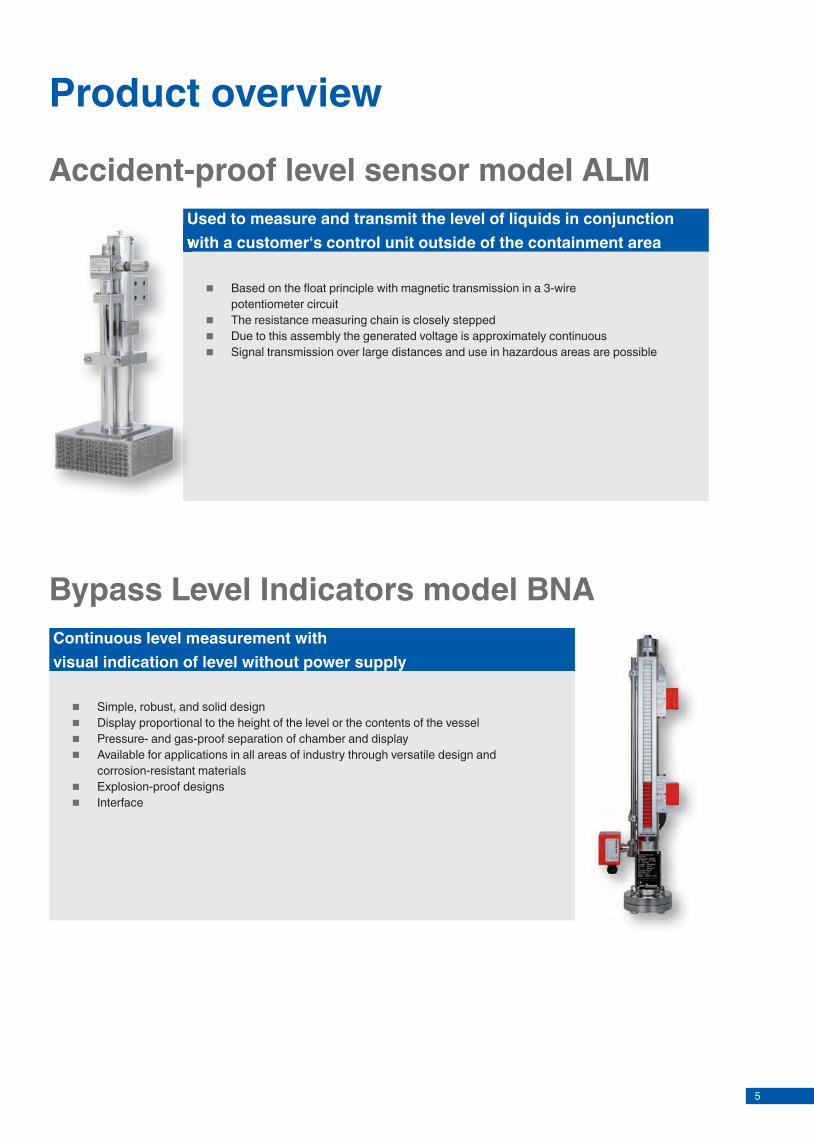
Accident-proof level sensor model ALM
Based on the fl oat principle with magnetic transmission in a 3-wire potentiometer circuit
The resistance measuring chain is closely stepped Due to this assembly the generated voltage is approximately continuous Signal transmission over large distances and use in hazardous areas are possible
Used to measure and transmit the level of liquids in conjunction with a customer‘s control unit outside of the containment area
Bypass Level Indicators model BNA
Simple, robust, and solid design Display proportional to the height of the level or the contents of the vessel Pressure- and gas-proof separation of chamber and display Available for applications in all areas of industry through versatile design and
corrosion-resistant materials Explosion-proof designs Interface
Continuous level measurement withvisual indication of level without power supply
Used to measure and transmit the level of liquids in conjunction with a customer‘s control unit outside of the containment area
Product overview

6
Level Sensors model FLR
Protocols: HART, Profi bus, Foundation Fieldbus ® Signal transmission over large distances Simple installation and commissioning, one-time calibration only,
no re-calibration necessary Display proportional to the height of the level or the contents of the vessel Set point relays continuously adjustable over full range High repeatability of set points Interface Application specifi c designs available Explosion-proof designs
Opto Level Switches are used for monitoring liquid levels
Magnetic Float Switches model FLS
Suitable for virtually all liquids Switching operation is without direct contact with the liquid, free of
wear and tear and does not require any power supply Universal signal processing of volt-free contacts:
PLC Control circuit to DIN NAMUR 60947-5-6
Multiple switch points in one unit (up to 8) Explosion-proof designs Interface Application specifi c designs available Simple installation and commissioning, maintenance-free
Detection of one or more distinct levels of a liquid
Product overview

7
KSR Level Sensors for Nuclear Power Plants - Application Limits
Opto Level Switch model OLS-H/-HT
Option: Interface High precision Independent of color, density, dielectric constant, conductivity and refactive index Small measurement volume Small size Explosion-proof designs
Opto Level Switches are used for monitoring liquid levels
Product overview
Level GaugeType BNA…
Level Transmit-ter Type MG… & ALM…
Level Switch Type BGU… & AV4…
Rod Electrodes
Single point level detection x x xMulti point level detection x x xContinuous level detection x xTemperature sensor as option available x x xRadiation resistance < 50 kGy < 5 MGy < 1 MGy < 250 kGy
Seismic On request 5 g SSE(3 Axis)
8g SSE (2 Axis) On request
Lifetime Up to 60 years16 years extendable to 60 years
16 years extendable to 60 years
Up to 60 years
Maintenance period > 2 years > 2 years > 2 years > 2 years

8
Level sensorFor Nuclear Power Plants with reed chain technologyModel ALM
Accident-proof level measurement sensor with reed chain technology, model ALM
Applications
■ Power generating equipment, power plants, nuclear power plants
■ Water basins ■ Cooling water tanks/pools
Normal operating conditions
■ Process- and system-specifi c solutions possible ■ Operating conditions:
- Operating temperature: T = -10°C ...+70 °C (+158 °F)- Operating pressure: ambient
■ Lengths: up to 20 m (65 ft) ■ Humidity: 100 % ■ Operational radiation dose: ≤ 160 kGy (16 MRad)
DescriptionALM Level Sensors are used to measure and transmit thelevel of liquids in conjunction with a customer’s control unitoutside of the containment area. It is based on the fl oatprinciple with magnetic transmission in a 3-wire potentiometer circuit. The resistance measuring chain is closely stepped. Due to this assembly the generated voltage is approximately continuous. Signal transmission over largedistances and use in hazardous areas are possible.
Level measurement
KSR data sheet ALM
Page 1 of 13KSR data sheet ALM ∙ 03/2015
Accident conditions
■ Accident temperature: 156 °C (312 °F) ■ Accident pressure: 7 bar (0.7 MPa) ■ Accident mission time: 1 year ■ Accident rad. dose: integrated 5.05 MGy (505 MRad) ■ Seismic acceleration: up to 2.5 g (higher accelerations
up to 5 g on demand)

9
Level sensorFor Nuclear Power Plants with reed chain technologyModel ALM
Accident-proof level measurement sensor with reed chain technology, model ALM
Applications
■ Power generating equipment, power plants, nuclear power plants
■ Water basins ■ Cooling water tanks/pools
Normal operating conditions
■ Process- and system-specifi c solutions possible ■ Operating conditions:
- Operating temperature: T = -10°C ...+70 °C (+158 °F)- Operating pressure: ambient
■ Lengths: up to 20 m (65 ft) ■ Humidity: 100 % ■ Operational radiation dose: ≤ 160 kGy (16 MRad)
DescriptionALM Level Sensors are used to measure and transmit thelevel of liquids in conjunction with a customer’s control unitoutside of the containment area. It is based on the fl oatprinciple with magnetic transmission in a 3-wire potentiometer circuit. The resistance measuring chain is closely stepped. Due to this assembly the generated voltage is approximately continuous. Signal transmission over largedistances and use in hazardous areas are possible.
Level measurement
KSR data sheet ALM
Page 1 of 13KSR data sheet ALM ∙ 03/2015
Accident conditions
■ Accident temperature: 156 °C (312 °F) ■ Accident pressure: 7 bar (0.7 MPa) ■ Accident mission time: 1 year ■ Accident rad. dose: integrated 5.05 MGy (505 MRad) ■ Seismic acceleration: up to 2.5 g (higher accelerations
up to 5 g on demand)
10
This device was designed without organic materials or active electronic components in any sensor and cabling part that might be affected by described accident conditions. The sen-sor will continue to function even in case of a Loss of Coolant Accident (LOCA) and can be fitted with a filter for protection against coarse debris. An accident-proof connection using mineral insulated cable is also available and meet the same standards as the integrated sensor units. For less critical applications, a connection using polymer insulated cable can be supplied.
This device is well-suited to retrofit the existing levelmeasurement as part of the wide range of post-accidentmonitoring systems.
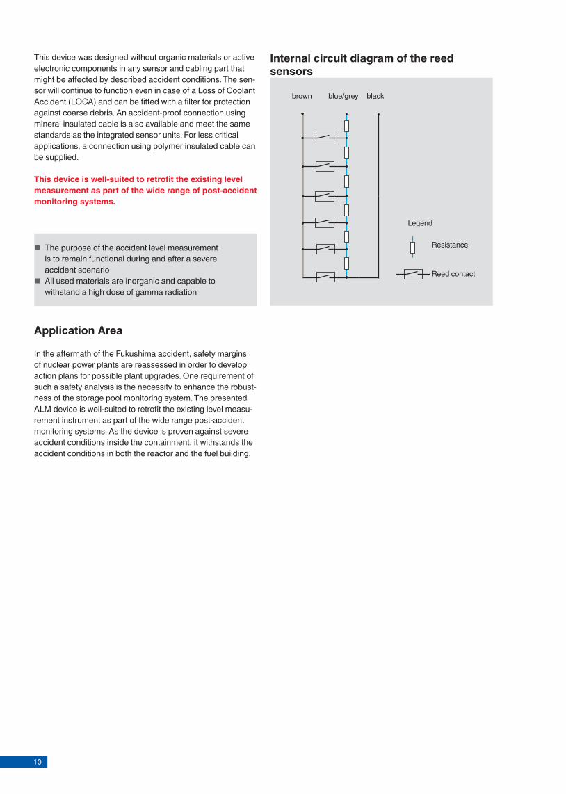
Internal circuit diagram of the reed sensors
brown blackblue/grey
Legend
Resistance
Reed contact
Application Area
In the aftermath of the Fukushima accident, safety margins of nuclear power plants are reassessed in order to develop action plans for possible plant upgrades. One requirement of such a safety analysis is the necessity to enhance the robust-ness of the storage pool monitoring system. The presented ALM device is well-suited to retrofit the existing level measu-rement instrument as part of the wide range post-accident monitoring systems. As the device is proven against severe accident conditions inside the containment, it withstands the accident conditions in both the reactor and the fuel building.
Page 2 of 13 KSR data sheet ALM ∙ 03/2015
■ The purpose of the accident level measurement is to remain functional during and after a severe accident scenario
■ All used materials are inorganic and capable to withstand a high dose of gamma radiation
Model overview
Qualification specifications
Page 3 of 13 KSR data sheet ALM ∙ 03/2015
The current qualification is based on KTA 3505. Qualification includes the sensor and the cable-connector, both with elec-trical safety class 1E. The qualification is based on theoretical analysis and/or physical tests. Major points included in this qualification are following:
■ Electromagnetic compatibility ■ Shock test ■ Functional test ■ Behavior upon plugging and unplugging ■ Climatic test ■ Thermal ageing and Radiological ageing ■ Accidental mechanical loads ■ Debris test ■ Performance during exposure to pressure, temperature
and humidity ■ Performance during exposure to high dose rates and post-
stressing.
Products are developed for and with AREVA GmbH. The accident-proof level measurement device is part of the stan-dard instrumentation in a recent project of AREVA.
Sensor model
Description Standard Special Feautures
Reed switch unit (RSU)
Magnetic floater unit (MFU)
Material stainless steel
Floater guide tube unit (FGTU)
Filter box Tempe-rature sensor PT-100
Redun-dant mea-suring equip-ment
Modular design
ALM-D1 Accident proof Level Measurement Devices
x x x x x
ALM-D2 Accident proof Level Measurement Devices
x x x
ALM-D3 Accident proof Level Measurement Devices
x x x x
ALM-D4 Accident proof Level Measurement Devices
x x x x x x
ALM-D5 Accident proof Level Devices
x x x x x x
ALM-D6 Accident proof Level Measurement Devices
x x x x x x

11
This device was designed without organic materials or active electronic components in any sensor and cabling part that might be affected by described accident conditions. The sen-sor will continue to function even in case of a Loss of Coolant Accident (LOCA) and can be fitted with a filter for protection against coarse debris. An accident-proof connection using mineral insulated cable is also available and meet the same standards as the integrated sensor units. For less critical applications, a connection using polymer insulated cable can be supplied.
This device is well-suited to retrofit the existing levelmeasurement as part of the wide range of post-accidentmonitoring systems.
Internal circuit diagram of the reed sensors
brown blackblue/grey
Legend
Resistance
Reed contact
Application Area
In the aftermath of the Fukushima accident, safety margins of nuclear power plants are reassessed in order to develop action plans for possible plant upgrades. One requirement of such a safety analysis is the necessity to enhance the robust-ness of the storage pool monitoring system. The presented ALM device is well-suited to retrofit the existing level measu-rement instrument as part of the wide range post-accident monitoring systems. As the device is proven against severe accident conditions inside the containment, it withstands the accident conditions in both the reactor and the fuel building.
Page 2 of 13 KSR data sheet ALM ∙ 03/2015
■ The purpose of the accident level measurement is to remain functional during and after a severe accident scenario
■ All used materials are inorganic and capable to withstand a high dose of gamma radiation
Model overview
Qualification specifications
Page 3 of 13 KSR data sheet ALM ∙ 03/2015
The current qualification is based on KTA 3505. Qualification includes the sensor and the cable-connector, both with elec-trical safety class 1E. The qualification is based on theoretical analysis and/or physical tests. Major points included in this qualification are following:
■ Electromagnetic compatibility ■ Shock test ■ Functional test ■ Behavior upon plugging and unplugging ■ Climatic test ■ Thermal ageing and Radiological ageing ■ Accidental mechanical loads ■ Debris test ■ Performance during exposure to pressure, temperature
and humidity ■ Performance during exposure to high dose rates and post-
stressing.
Products are developed for and with AREVA GmbH. The accident-proof level measurement device is part of the stan-dard instrumentation in a recent project of AREVA.
Sensor model
Description Standard Special Feautures
Reed switch unit (RSU)
Magnetic floater unit (MFU)
Material stainless steel
Floater guide tube unit (FGTU)
Filter box Tempe-rature sensor PT-100
Redun-dant mea-suring equip-ment
Modular design
ALM-D1 Accident proof Level Measurement Devices
x x x x x
ALM-D2 Accident proof Level Measurement Devices
x x x
ALM-D3 Accident proof Level Measurement Devices
x x x x
ALM-D4 Accident proof Level Measurement Devices
x x x x x x
ALM-D5 Accident proof Level Devices
x x x x x x
ALM-D6 Accident proof Level Measurement Devices
x x x x x x

12
Accident-proof Level Measurement Device, model ALM-D1Internally mounted for sumps
Technical specifi cationsElectrical connection Male plug
Mounting Welding bracket
Guide tube unit diameter 60.3 mm (2 “)
Float Titanium ZTS45/200/SMCO
Contact separation 16 mm (0.63 “)
Overall resistance of the measuring chain
< 500 Ohm
Connection cable to transmitter
Available on request
Control unit Available on request
Mounting position Vertical
Material Stainless steel
Chemical resistance Boron (B-10 32%) = 1750 ppmChloride = 0.2 mg/kgNaOH = 0.5•wt %Na2S2O3 = 3.5•wt %
Page 4 of 13 KSR data sheet ALM ∙ 03/2015
Accident conditionsMaximum temperature 156 °C (312 °F)
Maximum pressure 5.5 bar (0.55 MPa) abs.
Humidity 100%
Radiation resistance 5.05 MGy (505 MRad) Dose rate 5kGy/h (0.5 MRad/h) (1 year)
Mechanical stress Load test 1.68g (3 axis)Excitation type: Sine sweepFrequency: 2..50 HzDisplacement: 10 mm (0.03 ft),1 Oct./min.
Load test 2.6g (3 axis)Excitation type: Sine sweepFrequency: 2..100 HzDisplacement: 10 mm (0.03 ft),10 Oct./min.
Response time < 30 s
Pollution severity 3.0 kg MD2 insulation material for pipes (glass wool material)53 g concrete particles (<250 μm)53 g paint and coating particles (solid matter)80 g Microtherm, microporous insulation material300 l clear water
Accuracy (for 320 mm measuring range) under accident conditions
30 mm
Normal operating conditionsTemperature range 0 °C to 70 °C (32 °F to 158 °F)
Pressure 7 bar (0.7 MPa) abs.
Operating life time min. 16 years
Humidity 100%
Radiation resistance 2.5 kGy (250 kRad) per year
Response time < 1 s
Accuracy (for 200 mm measuring range)
≤ 16 mm
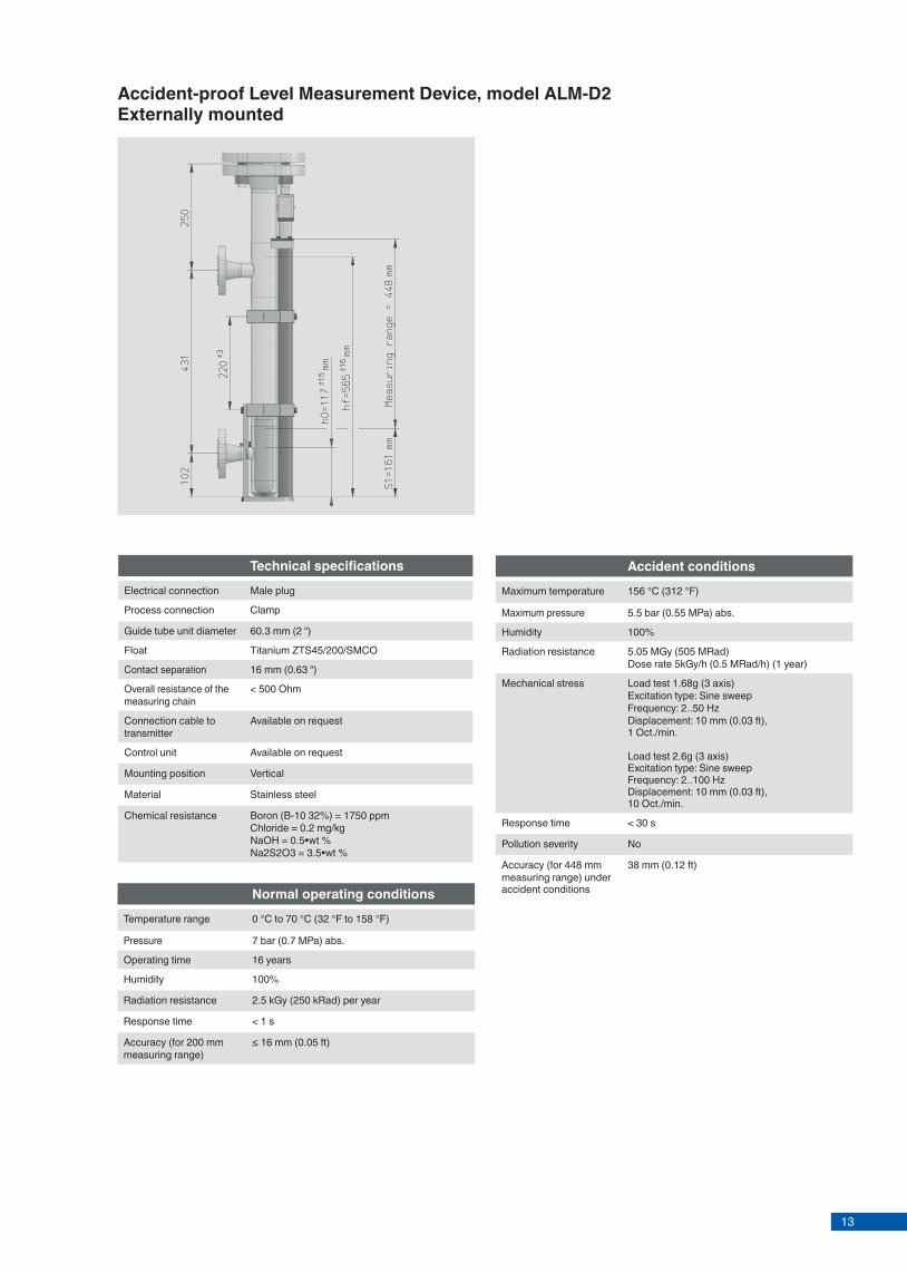
Accident-proof Level Measurement Device, model ALM-D2Externally mounted
Page 5 of 13KSR data sheet ALM ∙ 03/2015
Accident conditionsMaximum temperature 156 °C (312 °F)
Maximum pressure 5.5 bar (0.55 MPa) abs.
Humidity 100%
Radiation resistance 5.05 MGy (505 MRad) Dose rate 5kGy/h (0.5 MRad/h) (1 year)
Mechanical stress Load test 1.68g (3 axis)Excitation type: Sine sweepFrequency: 2..50 HzDisplacement: 10 mm (0.03 ft),1 Oct./min.
Load test 2.6g (3 axis)Excitation type: Sine sweepFrequency: 2..100 HzDisplacement: 10 mm (0.03 ft),10 Oct./min.
Response time < 30 s
Pollution severity No
Accuracy (for 448 mm measuring range) under accident conditions
38 mm (0.12 ft)
Normal operating conditionsTemperature range 0 °C to 70 °C (32 °F to 158 °F)
Pressure 7 bar (0.7 MPa) abs.
Operating time 16 years
Humidity 100%
Radiation resistance 2.5 kGy (250 kRad) per year
Response time < 1 s
Accuracy (for 200 mm measuring range)
≤ 16 mm (0.05 ft)
Technical specifi cationsElectrical connection Male plug
Process connection Clamp
Guide tube unit diameter 60.3 mm (2 “)
Float Titanium ZTS45/200/SMCO
Contact separation 16 mm (0.63 “)
Overall resistance of the measuring chain
< 500 Ohm
Connection cable to transmitter
Available on request
Control unit Available on request
Mounting position Vertical
Material Stainless steel
Chemical resistance Boron (B-10 32%) = 1750 ppmChloride = 0.2 mg/kgNaOH = 0.5•wt %Na2S2O3 = 3.5•wt %
13
Accident-proof Level Measurement Device, model ALM-D1Internally mounted for sumps
Technical specifi cationsElectrical connection Male plug
Mounting Welding bracket
Guide tube unit diameter 60.3 mm (2 “)
Float Titanium ZTS45/200/SMCO
Contact separation 16 mm (0.63 “)
Overall resistance of the measuring chain
< 500 Ohm
Connection cable to transmitter
Available on request
Control unit Available on request
Mounting position Vertical
Material Stainless steel
Chemical resistance Boron (B-10 32%) = 1750 ppmChloride = 0.2 mg/kgNaOH = 0.5•wt %Na2S2O3 = 3.5•wt %
Page 4 of 13 KSR data sheet ALM ∙ 03/2015
Accident conditionsMaximum temperature 156 °C (312 °F)
Maximum pressure 5.5 bar (0.55 MPa) abs.
Humidity 100%
Radiation resistance 5.05 MGy (505 MRad) Dose rate 5kGy/h (0.5 MRad/h) (1 year)
Mechanical stress Load test 1.68g (3 axis)Excitation type: Sine sweepFrequency: 2..50 HzDisplacement: 10 mm (0.03 ft),1 Oct./min.
Load test 2.6g (3 axis)Excitation type: Sine sweepFrequency: 2..100 HzDisplacement: 10 mm (0.03 ft),10 Oct./min.
Response time < 30 s
Pollution severity 3.0 kg MD2 insulation material for pipes (glass wool material)53 g concrete particles (<250 μm)53 g paint and coating particles (solid matter)80 g Microtherm, microporous insulation material300 l clear water
Accuracy (for 320 mm measuring range) under accident conditions
30 mm
Normal operating conditionsTemperature range 0 °C to 70 °C (32 °F to 158 °F)
Pressure 7 bar (0.7 MPa) abs.
Operating life time min. 16 years
Humidity 100%
Radiation resistance 2.5 kGy (250 kRad) per year
Response time < 1 s
Accuracy (for 200 mm measuring range)
≤ 16 mm
Accident-proof Level Measurement Device, model ALM-D2Externally mounted
Page 5 of 13KSR data sheet ALM ∙ 03/2015
Accident conditionsMaximum temperature 156 °C (312 °F)
Maximum pressure 5.5 bar (0.55 MPa) abs.
Humidity 100%
Radiation resistance 5.05 MGy (505 MRad) Dose rate 5kGy/h (0.5 MRad/h) (1 year)
Mechanical stress Load test 1.68g (3 axis)Excitation type: Sine sweepFrequency: 2..50 HzDisplacement: 10 mm (0.03 ft),1 Oct./min.
Load test 2.6g (3 axis)Excitation type: Sine sweepFrequency: 2..100 HzDisplacement: 10 mm (0.03 ft),10 Oct./min.
Response time < 30 s
Pollution severity No
Accuracy (for 448 mm measuring range) under accident conditions
38 mm (0.12 ft)
Normal operating conditionsTemperature range 0 °C to 70 °C (32 °F to 158 °F)
Pressure 7 bar (0.7 MPa) abs.
Operating time 16 years
Humidity 100%
Radiation resistance 2.5 kGy (250 kRad) per year
Response time < 1 s
Accuracy (for 200 mm measuring range)
≤ 16 mm (0.05 ft)
Technical specifi cationsElectrical connection Male plug
Process connection Clamp
Guide tube unit diameter 60.3 mm (2 “)
Float Titanium ZTS45/200/SMCO
Contact separation 16 mm (0.63 “)
Overall resistance of the measuring chain
< 500 Ohm
Connection cable to transmitter
Available on request
Control unit Available on request
Mounting position Vertical
Material Stainless steel
Chemical resistance Boron (B-10 32%) = 1750 ppmChloride = 0.2 mg/kgNaOH = 0.5•wt %Na2S2O3 = 3.5•wt %
14
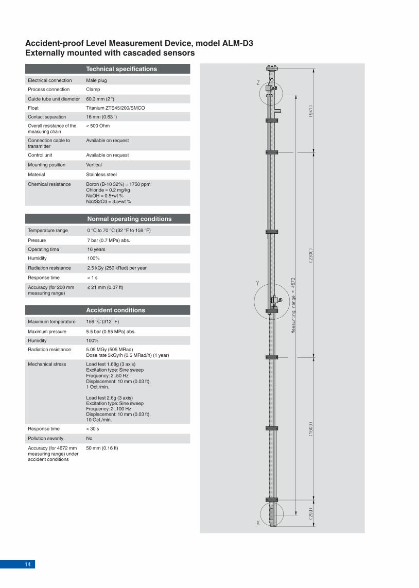
Accident-proof Level Measurement Device, model ALM-D3Externally mounted with cascaded sensors
Page 6 of 13 KSR data sheet ALM ∙ 03/2015
Accident conditionsMaximum temperature 156 °C (312 °F)
Maximum pressure 5.5 bar (0.55 MPa) abs.
Humidity 100%
Radiation resistance 5.05 MGy (505 MRad) Dose rate 5kGy/h (0.5 MRad/h) (1 year)
Mechanical stress Load test 1.68g (3 axis)Excitation type: Sine sweepFrequency: 2..50 HzDisplacement: 10 mm (0.03 ft),1 Oct./min.
Load test 2.6g (3 axis)Excitation type: Sine sweepFrequency: 2..100 HzDisplacement: 10 mm (0.03 ft),10 Oct./min.
Response time < 30 s
Pollution severity No
Accuracy (for 4672 mm measuring range) under accident conditions
50 mm (0.16 ft)
Normal operating conditionsTemperature range 0 °C to 70 °C (32 °F to 158 °F)
Pressure 7 bar (0.7 MPa) abs.
Operating time 16 years
Humidity 100%
Radiation resistance 2.5 kGy (250 kRad) per year
Response time < 1 s
Accuracy (for 200 mm measuring range)
≤ 21 mm (0.07 ft)
Technical specifi cationsElectrical connection Male plug
Process connection Clamp
Guide tube unit diameter 60.3 mm (2 “)
Float Titanium ZTS45/200/SMCO
Contact separation 16 mm (0.63 “)
Overall resistance of the measuring chain
< 500 Ohm
Connection cable to transmitter
Available on request
Control unit Available on request
Mounting position Vertical
Material Stainless steel
Chemical resistance Boron (B-10 32%) = 1750 ppmChloride = 0.2 mg/kgNaOH = 0.5•wt %Na2S2O3 = 3.5•wt %
Accident-proof Level Measurement Device, model ALM-D4Internally mounted for fuel pools
Page 7 of 13KSR data sheet ALM ∙ 03/2015
Accident conditionsMaximum temperature 156 °C (312 °F)
Maximum pressure 5.5 bar (0.55 MPa) abs.
Humidity 100%
Radiation resistance 5.05 MGy (505 MRad) Dose rate 5kGy/h (0.5 MRad/h) (1 year)
Mechanical stress Load test 1.68g (3 axis)Excitation type: Sine sweepFrequency: 2..50 HzDisplacement: 10 mm (0.03 ft),1 Oct./min.
Load test 2.6g (3 axis)Excitation type: Sine sweepFrequency: 2..100 HzDisplacement: 10 mm (0.03 ft),10 Oct./min.
Response time < 30 s
Pollution severity 3.0 kg MD2 insulation material for pipes (glass wool material)53 g concrete particles (<250 μm)53 g paint and coating particles (solid matter)80 g Microtherm, microporous insulation material300 l clear water
Accuracy (for 3968 mm measuring range) under accident conditions
30 mm (0.1 ft)
Normal operating conditionsTemperature range 0 °C to 70 °C (32 °F to 158 °F)
Pressure 7 bar (0.7 MPa) abs.
Operating time 16 years
Humidity 100%
Radiation resistance 2.5 kGy (250 kRad) per year
Response time < 1 s
Accuracy (for 200 mm measuring range)
≤ 16 mm (0.05 ft)
Technical specifi cationsElectrical connection Male plug
Process connection Mounting fl ange
Guide tube unit diameter 60.3 mm (2 “)
Float Titanium ZTS45/200/SMCO
Contact separation 16 mm (0.63 “)
Overall resistance of the measuring chain
< 500 Ohm
Connection cable to transmitter
Available on request
Control unit Available on request
Mounting position Vertical
Material Stainless steel
Chemical resistance Boron (B-10 32%) = 1750 ppmChloride = 0.2 mg/kgNaOH = 0.5•wt %Na2S2O3 = 3.5•wt %

15
Accident-proof Level Measurement Device, model ALM-D3Externally mounted with cascaded sensors
Page 6 of 13 KSR data sheet ALM ∙ 03/2015
Accident conditionsMaximum temperature 156 °C (312 °F)
Maximum pressure 5.5 bar (0.55 MPa) abs.
Humidity 100%
Radiation resistance 5.05 MGy (505 MRad) Dose rate 5kGy/h (0.5 MRad/h) (1 year)
Mechanical stress Load test 1.68g (3 axis)Excitation type: Sine sweepFrequency: 2..50 HzDisplacement: 10 mm (0.03 ft),1 Oct./min.
Load test 2.6g (3 axis)Excitation type: Sine sweepFrequency: 2..100 HzDisplacement: 10 mm (0.03 ft),10 Oct./min.
Response time < 30 s
Pollution severity No
Accuracy (for 4672 mm measuring range) under accident conditions
50 mm (0.16 ft)
Normal operating conditionsTemperature range 0 °C to 70 °C (32 °F to 158 °F)
Pressure 7 bar (0.7 MPa) abs.
Operating time 16 years
Humidity 100%
Radiation resistance 2.5 kGy (250 kRad) per year
Response time < 1 s
Accuracy (for 200 mm measuring range)
≤ 21 mm (0.07 ft)
Technical specifi cationsElectrical connection Male plug
Process connection Clamp
Guide tube unit diameter 60.3 mm (2 “)
Float Titanium ZTS45/200/SMCO
Contact separation 16 mm (0.63 “)
Overall resistance of the measuring chain
< 500 Ohm
Connection cable to transmitter
Available on request
Control unit Available on request
Mounting position Vertical
Material Stainless steel
Chemical resistance Boron (B-10 32%) = 1750 ppmChloride = 0.2 mg/kgNaOH = 0.5•wt %Na2S2O3 = 3.5•wt %
Accident-proof Level Measurement Device, model ALM-D4Internally mounted for fuel pools
Page 7 of 13KSR data sheet ALM ∙ 03/2015
Accident conditionsMaximum temperature 156 °C (312 °F)
Maximum pressure 5.5 bar (0.55 MPa) abs.
Humidity 100%
Radiation resistance 5.05 MGy (505 MRad) Dose rate 5kGy/h (0.5 MRad/h) (1 year)
Mechanical stress Load test 1.68g (3 axis)Excitation type: Sine sweepFrequency: 2..50 HzDisplacement: 10 mm (0.03 ft),1 Oct./min.
Load test 2.6g (3 axis)Excitation type: Sine sweepFrequency: 2..100 HzDisplacement: 10 mm (0.03 ft),10 Oct./min.
Response time < 30 s
Pollution severity 3.0 kg MD2 insulation material for pipes (glass wool material)53 g concrete particles (<250 μm)53 g paint and coating particles (solid matter)80 g Microtherm, microporous insulation material300 l clear water
Accuracy (for 3968 mm measuring range) under accident conditions
30 mm (0.1 ft)
Normal operating conditionsTemperature range 0 °C to 70 °C (32 °F to 158 °F)
Pressure 7 bar (0.7 MPa) abs.
Operating time 16 years
Humidity 100%
Radiation resistance 2.5 kGy (250 kRad) per year
Response time < 1 s
Accuracy (for 200 mm measuring range)
≤ 16 mm (0.05 ft)
Technical specifi cationsElectrical connection Male plug
Process connection Mounting fl ange
Guide tube unit diameter 60.3 mm (2 “)
Float Titanium ZTS45/200/SMCO
Contact separation 16 mm (0.63 “)
Overall resistance of the measuring chain
< 500 Ohm
Connection cable to transmitter
Available on request
Control unit Available on request
Mounting position Vertical
Material Stainless steel
Chemical resistance Boron (B-10 32%) = 1750 ppmChloride = 0.2 mg/kgNaOH = 0.5•wt %Na2S2O3 = 3.5•wt %

16
Accident-proof Level Measurement Device, model ALM-D5Internally mounted with redundant sensor
Page 8 of 13 KSR data sheet ALM ∙ 03/2015
Accident conditionsMaximum temperature 156 °C (312 °F)
Maximum pressure 7.5 bar (0.75 MPa) abs.
Humidity 100%
Radiation resistance 5.05 MGy (505 MRad) Dose rate 5kGy/h (0.5 MRad/h) (1 year)
Mechanical stress Load test 1.68g (3 axis)Excitation type: Sine sweepFrequency: 2..50 HzDisplacement: 10 mm (0.03 ft),1 Oct./min.
Load test 2.6g (3 axis)Excitation type: Sine sweepFrequency: 2..100 HzDisplacement: 10 mm (0.03 ft),10 Oct./min.
Response time < 30 s
Pollution severity 3.0 kg MD2 insulation material for pipes (glass wool material)53 g concrete particles (<250 μm)53 g paint and coating particles (solid matter)80 g Microtherm, microporous insulation material300 l clear water
Accuracy (for 9344 mm / 1088 mm measuring range) under accident conditionsLong Range/Short Range 481 mm / 68 mm (1.58 ft / 0.22 ft)
Normal operating conditionsTemperature range 0 °C to 70 °C (32 °F to 158 °F)
Pressure 7 bar (0.7 MPa) abs.
Operating time 16 years
Humidity 100%
Radiation resistance 2.5 kGy (250 kRad) per year
Response time < 1 s
Accuracy Long Range/Short Range 107 mm / 19 mm (0.35 ft / 0.06 ft)
Technical specifi cationsElectrical connection Male plug
Process connection Mounting fl ange
Guide tube unit diameter 60.3 mm (2 “)
Float Titanium ZTS45/200/SMCO
Contact separation 16 mm (0.63 “)
Overall resistance of the measuring chain
< 500 Ohm
Connection cable to transmitter
Available on request
Control unit Available on request
Mounting position Vertical
Material Stainless steel
Chemical resistance Boron (B-10 32%) = 1750 ppmChloride = 0.2 mg/kgNaOH = 0.5•wt %Na2S2O3 = 3.5•wt %
Accident-proof Level Measurement Device, model ALM-D6Internally mounted with cascaded sensors
Page 9 of 13KSR data sheet ALM ∙ 03/2015
Accident conditionsMaximum temperature 156 °C (312 °F)
Maximum pressure 7.5 bar (0.75 MPa) abs.
Humidity 100%
Radiation resistance 5.05 MGy (505 MRad) Dose rate 5kGy/h (0.5 MRad/h) (1 year)
Mechanical stress Load test 1.68g (3 axis)Excitation type: Sine sweepFrequency: 2..50 HzDisplacement: 10 mm (0.03 ft),1 Oct./min.
Load test 2.6g (3 axis)Excitation type: Sine sweepFrequency: 2..100 HzDisplacement: 10 mm (0.03 ft),10 Oct./min.
Response time < 30 s
Pollution severity 3.0 kg MD2 insulation material for pipes (glass wool material)53 g concrete particles (<250 μm)53 g paint and coating particles (solid matter)80 g Microtherm, microporous insulation material300 l clear water
Accuracy (for 11776 mm measuring range) under accident conditionsLong Range/Short Range
481 mm (1.58 ft)
Normal operating conditionsTemperature range 0 °C to 70 °C (32 °F to 158 °F)
Pressure 7 bar (0.7 MPa) abs.
Operating time 16 years
Humidity 100%
Radiation resistance 2.5 kGy (250 kRad) per year
Response time < 1 s
Accuracy Long Range 107 mm (0.35 ft)
Technical specifi cationsElectrical connection Male plug
Process connection Welding bracket
Guide tube unit diameter 60.3 mm (2 “)
Float Titanium ZTS45/200/SMCO
Contact separation 16 mm (0.63 “)
Overall resistance of the measuring chain
< 500 Ohm
Connection cable to transmitter
Available on request
Control unit Available on request
Mounting position Vertical
Material Stainless steel
Chemical resistance Boron (B-10 32%) = 1750 ppmChloride = 0.2 mg/kgNaOH = 0.5•wt %Na2S2O3 = 3.5•wt %

17
Accident-proof Level Measurement Device, model ALM-D5Internally mounted with redundant sensor
Page 8 of 13 KSR data sheet ALM ∙ 03/2015
Accident conditionsMaximum temperature 156 °C (312 °F)
Maximum pressure 7.5 bar (0.75 MPa) abs.
Humidity 100%
Radiation resistance 5.05 MGy (505 MRad) Dose rate 5kGy/h (0.5 MRad/h) (1 year)
Mechanical stress Load test 1.68g (3 axis)Excitation type: Sine sweepFrequency: 2..50 HzDisplacement: 10 mm (0.03 ft),1 Oct./min.
Load test 2.6g (3 axis)Excitation type: Sine sweepFrequency: 2..100 HzDisplacement: 10 mm (0.03 ft),10 Oct./min.
Response time < 30 s
Pollution severity 3.0 kg MD2 insulation material for pipes (glass wool material)53 g concrete particles (<250 μm)53 g paint and coating particles (solid matter)80 g Microtherm, microporous insulation material300 l clear water
Accuracy (for 9344 mm / 1088 mm measuring range) under accident conditionsLong Range/Short Range 481 mm / 68 mm (1.58 ft / 0.22 ft)
Normal operating conditionsTemperature range 0 °C to 70 °C (32 °F to 158 °F)
Pressure 7 bar (0.7 MPa) abs.
Operating time 16 years
Humidity 100%
Radiation resistance 2.5 kGy (250 kRad) per year
Response time < 1 s
Accuracy Long Range/Short Range 107 mm / 19 mm (0.35 ft / 0.06 ft)
Technical specifi cationsElectrical connection Male plug
Process connection Mounting fl ange
Guide tube unit diameter 60.3 mm (2 “)
Float Titanium ZTS45/200/SMCO
Contact separation 16 mm (0.63 “)
Overall resistance of the measuring chain
< 500 Ohm
Connection cable to transmitter
Available on request
Control unit Available on request
Mounting position Vertical
Material Stainless steel
Chemical resistance Boron (B-10 32%) = 1750 ppmChloride = 0.2 mg/kgNaOH = 0.5•wt %Na2S2O3 = 3.5•wt %
Accident-proof Level Measurement Device, model ALM-D6Internally mounted with cascaded sensors
Page 9 of 13KSR data sheet ALM ∙ 03/2015
Accident conditionsMaximum temperature 156 °C (312 °F)
Maximum pressure 7.5 bar (0.75 MPa) abs.
Humidity 100%
Radiation resistance 5.05 MGy (505 MRad) Dose rate 5kGy/h (0.5 MRad/h) (1 year)
Mechanical stress Load test 1.68g (3 axis)Excitation type: Sine sweepFrequency: 2..50 HzDisplacement: 10 mm (0.03 ft),1 Oct./min.
Load test 2.6g (3 axis)Excitation type: Sine sweepFrequency: 2..100 HzDisplacement: 10 mm (0.03 ft),10 Oct./min.
Response time < 30 s
Pollution severity 3.0 kg MD2 insulation material for pipes (glass wool material)53 g concrete particles (<250 μm)53 g paint and coating particles (solid matter)80 g Microtherm, microporous insulation material300 l clear water
Accuracy (for 11776 mm measuring range) under accident conditionsLong Range/Short Range
481 mm (1.58 ft)
Normal operating conditionsTemperature range 0 °C to 70 °C (32 °F to 158 °F)
Pressure 7 bar (0.7 MPa) abs.
Operating time 16 years
Humidity 100%
Radiation resistance 2.5 kGy (250 kRad) per year
Response time < 1 s
Accuracy Long Range 107 mm (0.35 ft)
Technical specifi cationsElectrical connection Male plug
Process connection Welding bracket
Guide tube unit diameter 60.3 mm (2 “)
Float Titanium ZTS45/200/SMCO
Contact separation 16 mm (0.63 “)
Overall resistance of the measuring chain
< 500 Ohm
Connection cable to transmitter
Available on request
Control unit Available on request
Mounting position Vertical
Material Stainless steel
Chemical resistance Boron (B-10 32%) = 1750 ppmChloride = 0.2 mg/kgNaOH = 0.5•wt %Na2S2O3 = 3.5•wt %

18
Example for ALM-D1 Example for ALM-D2
Page 10 of 13 KSR data sheet ALM ∙ 03/2015
Application examples
The level measurement devices ALM-D1 is used to detect breaks in the pipes or leaks on valves and pumps of theResidual Heat Removal System and Containment HeatRemoval System during normal operation, outages andaccidents throughout the complete NPP life cycle.
The purpose of the level measurement device ALM-D2 at the Flooding Valve Outlet is to reliably detect any leakage and accidental or intentional triggering of the passive fl ooding de-vice valves. The valves discharge the water from the IRWST into the containment’s spreading area. Premature presence of water must be avoided during normal operation of the plant due to the risk of generation of hydrogen should the molten core fl ow into the already fl ooded spreading area. During a severe accident, the passive fl ooding valve is essential for cooling the escaped corium melt in the spreading area.
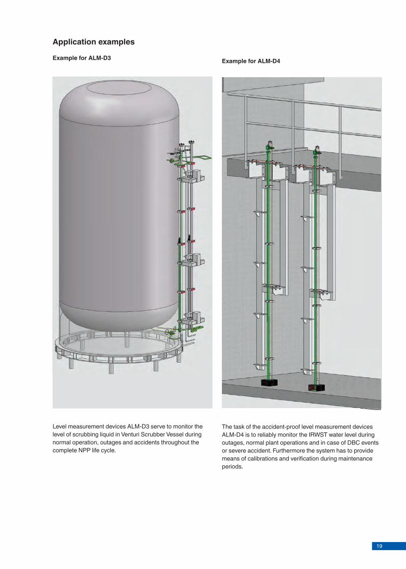
Example for ALM-D3
Application examples
Example for ALM-D4
Page 11 of 13KSR data sheet ALM ∙ 03/2015
The task of the accident-proof level measurement devices ALM-D4 is to reliably monitor the IRWST water level during outages, normal plant operations and in case of DBC events or severe accident. Furthermore the system has to provide means of calibrations and verifi cation during maintenance periods.
Level measurement devices ALM-D3 serve to monitor the level of scrubbing liquid in Venturi Scrubber Vessel during normal operation, outages and accidents throughout the complete NPP life cycle.
19
Example for ALM-D1 Example for ALM-D2
Page 10 of 13 KSR data sheet ALM ∙ 03/2015
Application examples
The level measurement devices ALM-D1 is used to detect breaks in the pipes or leaks on valves and pumps of theResidual Heat Removal System and Containment HeatRemoval System during normal operation, outages andaccidents throughout the complete NPP life cycle.
The purpose of the level measurement device ALM-D2 at the Flooding Valve Outlet is to reliably detect any leakage and accidental or intentional triggering of the passive fl ooding de-vice valves. The valves discharge the water from the IRWST into the containment’s spreading area. Premature presence of water must be avoided during normal operation of the plant due to the risk of generation of hydrogen should the molten core fl ow into the already fl ooded spreading area. During a severe accident, the passive fl ooding valve is essential for cooling the escaped corium melt in the spreading area.
Example for ALM-D3
Application examples
Example for ALM-D4
Page 11 of 13KSR data sheet ALM ∙ 03/2015
The task of the accident-proof level measurement devices ALM-D4 is to reliably monitor the IRWST water level during outages, normal plant operations and in case of DBC events or severe accident. Furthermore the system has to provide means of calibrations and verifi cation during maintenance periods.
Level measurement devices ALM-D3 serve to monitor the level of scrubbing liquid in Venturi Scrubber Vessel during normal operation, outages and accidents throughout the complete NPP life cycle.
20Page 12 of 13 KSR data sheet ALM ∙ 03/2015
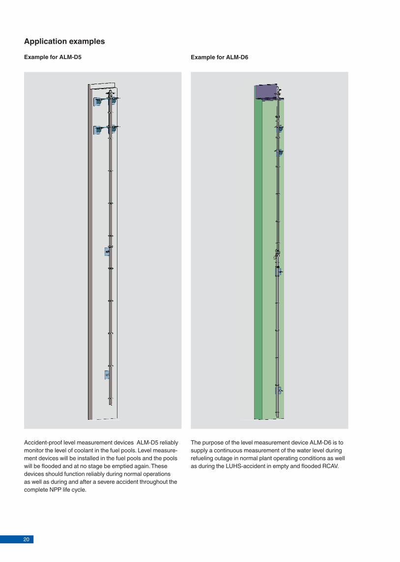
Example for ALM-D5 Example for ALM-D6
Accident-proof level measurement devices ALM-D5 reliably monitor the level of coolant in the fuel pools. Level measure-ment devices will be installed in the fuel pools and the pools will be fl ooded and at no stage be emptied again. These devices should function reliably during normal operations as well as during and after a severe accident throughout the complete NPP life cycle.
The purpose of the level measurement device ALM-D6 is to supply a continuous measurement of the water level during refueling outage in normal plant operating conditions as well as during the LUHS-accident in empty and fl ooded RCAV.
Application examples
Bypass level indicatorWith magnetic displayModel BNA for nuclear power plants
Bypass level indicator, model BNA with level sensor and magnetic switch
Applications
■ Continuous level indication without power supply ■ Indication of the level proportional to height ■ Individual design and corrosion resistant materials make
the products suitable for a broad range of applications ■ Chemical, petrochemical industry, oil and natural gas
extraction (on- and off shore), shipbuilding, machine building, power generating equipment, power plants
■ Process water and drinking water treatment, food industry, pharmaceutical industry
Special features
■ Process- and system-specifi c production ■ Operating limits:
- Operating temperature: T = -196 ... +450 °C- Operating pressure: P = vacuum to 400 bar- Limit density: ρ ≥ 340 kg/m3
■ Wide variety of diff erent process connections and materials
■ Mounting of level sensors and magnetic switches possible as an option
■ Explosion-protected versions
DescriptionThe bypass level indicator model BNA consists of a bypass chamber, which, as a communicating tube, is connected laterally to a vessel via at least 2 process connections (fl anged, threaded or welded). Through this type of arrangement, the level in the bypass chamber corresponds to the level in the vessel. The fl oat with a built-in permanent magnetic system, which is mounted within the bypass chamber, transmits the liquid level, contact-free, to the magnetic display mounted to the outside of the bypass chamber. In this are fi tted, at 10 mm intervals, two-coloured plastic rollers or stainless steel fl aps with bar magnets.
Through the magnetic fi eld of the permanent magnetic system in the fl oat, the display elements, through the wall of the bypass chamber, are turned through 180°. For an increasing level from white to red; for a falling level from red to white.Thus the bypass level indicator clearly displays the level of a vessel without power supply.
Level measurement
Data sheets showing similar products and accessories:Float; model BFTMagnetic display; model BMDReed sensor; model BLRMagnetic switch; model BGU
KSR data sheet BNA for NPP
Page 1 of 11KSR data sheet BNA for NPP ∙ 04/2015

21Page 12 of 13 KSR data sheet ALM ∙ 03/2015
Example for ALM-D5 Example for ALM-D6
Accident-proof level measurement devices ALM-D5 reliably monitor the level of coolant in the fuel pools. Level measure-ment devices will be installed in the fuel pools and the pools will be fl ooded and at no stage be emptied again. These devices should function reliably during normal operations as well as during and after a severe accident throughout the complete NPP life cycle.
The purpose of the level measurement device ALM-D6 is to supply a continuous measurement of the water level during refueling outage in normal plant operating conditions as well as during the LUHS-accident in empty and fl ooded RCAV.
Application examples
Bypass level indicatorWith magnetic displayModel BNA for nuclear power plants
Bypass level indicator, model BNA with level sensor and magnetic switch
Applications
■ Continuous level indication without power supply ■ Indication of the level proportional to height ■ Individual design and corrosion resistant materials make
the products suitable for a broad range of applications ■ Chemical, petrochemical industry, oil and natural gas
extraction (on- and off shore), shipbuilding, machine building, power generating equipment, power plants
■ Process water and drinking water treatment, food industry, pharmaceutical industry
Special features
■ Process- and system-specifi c production ■ Operating limits:
- Operating temperature: T = -196 ... +450 °C- Operating pressure: P = vacuum to 400 bar- Limit density: ρ ≥ 340 kg/m3
■ Wide variety of diff erent process connections and materials
■ Mounting of level sensors and magnetic switches possible as an option
■ Explosion-protected versions
DescriptionThe bypass level indicator model BNA consists of a bypass chamber, which, as a communicating tube, is connected laterally to a vessel via at least 2 process connections (fl anged, threaded or welded). Through this type of arrangement, the level in the bypass chamber corresponds to the level in the vessel. The fl oat with a built-in permanent magnetic system, which is mounted within the bypass chamber, transmits the liquid level, contact-free, to the magnetic display mounted to the outside of the bypass chamber. In this are fi tted, at 10 mm intervals, two-coloured plastic rollers or stainless steel fl aps with bar magnets.
Through the magnetic fi eld of the permanent magnetic system in the fl oat, the display elements, through the wall of the bypass chamber, are turned through 180°. For an increasing level from white to red; for a falling level from red to white.Thus the bypass level indicator clearly displays the level of a vessel without power supply.
Level measurement
Data sheets showing similar products and accessories:Float; model BFTMagnetic display; model BMDReed sensor; model BLRMagnetic switch; model BGU
KSR data sheet BNA for NPP
Page 1 of 11KSR data sheet BNA for NPP ∙ 04/2015

22Page 2 of 11 KSR data sheet BNA for NPP ∙ 04/2015
Further special features
■ Simple, robust and solid design, long service life ■ Bypass chamber and float from stainless steel 1.4571,
1.4404 or special materials ■ Pressure- and gas-tight separation between measuring
and display chamber ■ Measuring and indicating of the level of aggressive,
combustible, toxic, hot and contaminated media ■ Functioning of the magnetic display guaranteed even in
the case of power failures ■ By using a variety of corrosion-resistant materials,
applicable for virtually all industrial applications ■ Continuous measurement of levels, independent of
physical and chemical changes of the media such as: Foaming, conductivity, dielectric constant, vapours, bubble formation, boiling effects
■ Interface-layer level measurement from ∆ density 100 kg/m3
■ Special versions: Food compliant, coatings, liquid gas, heating jacket
■ Nuclear qualified IEEE (E1)
Illustration of the principle
Design and operating principle
■ In a communicating bypass chamber mounted to the side of a vessel a float moves with the level of the medium to be measured.
■ The magnetic field of the radial-symmetric magnetic system positioned in the float activates the magnetic display attached to the outside of the bypass chamber as well as the switching and measuring elements.
Connection housing(only with option magnetic switch or level sensor)
Magnetic display
Float(with magnetic system)
Bypass chamber
Magnetic system
The magnetic system is assembled from a pole disc and various magnets. These can be individually adapted to the different chamber dimensions and for temperatures up to 450 °C.
Field lines
Magnets
Pole disc
Page 3 of 11KSR data sheet BNA for NPP ∙ 04/2015
Model overviewBypass level indicator
Approval Material Max. pressure in bar
Medium temperature in °C
with-out
Ex c Ex c, GL
Ex c, DNV
GL DNV ABS IEEE344
Standard version, model BNA-S
x x x x x x x x Stainless steel 1.4571 (316Ti), 1.4404 (316L), 1.4401/1.4404 (316/316L)
64 -196 ... +450
High-pressure version, model BNA-H
x x x x x x * Stainless steel 1.4571 (316Ti), 1.4404 (316L)
400 -196 ... +450
DUPlus version, standard, model BNA-SD
x x * Stainless steel 1.4571 (316Ti), 1.4404 (316L), 1.4401/1.4404 (316/316L)
64 -196 ... +450
DUPlus version, high pressure, model BNA-HD
x x * Stainless steel 1.4571 (316Ti), 1.4404 (316L), 1.4401/1.4404 (316/316L)
160 -196 ... +450
Special materials, model BNA-X
x x * Stainless steel 6Mo 1.4547 (UNS S31254)
250 -196 ... +450
x x x x x x * Hastelloy C276 (2.4819) 160 -196 ... +450
Ex approvalsExplosion protection
Ignition protection type
Model Zone Approval number
ATEX Ex c BNA-S, BNA-H, BNA-SD, BNA-HD, BNA-X
Zone 0/1, gas KEMA 02 ATEX 2106 X ll 1/2 G c T1 ... T6
Ex c + GL BNA-S, BNA-H, BNA-X Zone 0/1, gas KEMA 02 ATEX 2106 X ll 1/2 G c T1 ... T6 + GL - 35 949 - 87
Ex c + DNV BNA-S, BNA-H, BNA-X Zone 0/1, gas KEMA 02 ATEX 2106 X ll 1/2 G c T1 ... T6 + DNV - A-11451
Type approvalApproval Model Approval number
GL BNA-S, BNA-H, BNA-X
GL - 35 949 - 87 HH
DNV BNA-S, BNA-H, BNA-X
DNV A-11451
ABS BNA-S ABS 07-HG218425-1-PDAGOST-R all 0959333IEEE 344 BNA-S -
Further approvals on request
* IEEE 344 on request

23Page 2 of 11 KSR data sheet BNA for NPP ∙ 04/2015
Further special features
■ Simple, robust and solid design, long service life ■ Bypass chamber and float from stainless steel 1.4571,
1.4404 or special materials ■ Pressure- and gas-tight separation between measuring
and display chamber ■ Measuring and indicating of the level of aggressive,
combustible, toxic, hot and contaminated media ■ Functioning of the magnetic display guaranteed even in
the case of power failures ■ By using a variety of corrosion-resistant materials,
applicable for virtually all industrial applications ■ Continuous measurement of levels, independent of
physical and chemical changes of the media such as: Foaming, conductivity, dielectric constant, vapours, bubble formation, boiling effects
■ Interface-layer level measurement from ∆ density 100 kg/m3
■ Special versions: Food compliant, coatings, liquid gas, heating jacket
■ Nuclear qualified IEEE (E1)
Illustration of the principle
Design and operating principle
■ In a communicating bypass chamber mounted to the side of a vessel a float moves with the level of the medium to be measured.
■ The magnetic field of the radial-symmetric magnetic system positioned in the float activates the magnetic display attached to the outside of the bypass chamber as well as the switching and measuring elements.
Connection housing(only with option magnetic switch or level sensor)
Magnetic display
Float(with magnetic system)
Bypass chamber
Magnetic system
The magnetic system is assembled from a pole disc and various magnets. These can be individually adapted to the different chamber dimensions and for temperatures up to 450 °C.
Field lines
Magnets
Pole disc
Page 3 of 11KSR data sheet BNA for NPP ∙ 04/2015
Model overviewBypass level indicator
Approval Material Max. pressure in bar
Medium temperature in °C
with-out
Ex c Ex c, GL
Ex c, DNV
GL DNV ABS IEEE344
Standard version, model BNA-S
x x x x x x x x Stainless steel 1.4571 (316Ti), 1.4404 (316L), 1.4401/1.4404 (316/316L)
64 -196 ... +450
High-pressure version, model BNA-H
x x x x x x * Stainless steel 1.4571 (316Ti), 1.4404 (316L)
400 -196 ... +450
DUPlus version, standard, model BNA-SD
x x * Stainless steel 1.4571 (316Ti), 1.4404 (316L), 1.4401/1.4404 (316/316L)
64 -196 ... +450
DUPlus version, high pressure, model BNA-HD
x x * Stainless steel 1.4571 (316Ti), 1.4404 (316L), 1.4401/1.4404 (316/316L)
160 -196 ... +450
Special materials, model BNA-X
x x * Stainless steel 6Mo 1.4547 (UNS S31254)
250 -196 ... +450
x x x x x x * Hastelloy C276 (2.4819) 160 -196 ... +450
Ex approvalsExplosion protection
Ignition protection type
Model Zone Approval number
ATEX Ex c BNA-S, BNA-H, BNA-SD, BNA-HD, BNA-X
Zone 0/1, gas KEMA 02 ATEX 2106 X ll 1/2 G c T1 ... T6
Ex c + GL BNA-S, BNA-H, BNA-X Zone 0/1, gas KEMA 02 ATEX 2106 X ll 1/2 G c T1 ... T6 + GL - 35 949 - 87
Ex c + DNV BNA-S, BNA-H, BNA-X Zone 0/1, gas KEMA 02 ATEX 2106 X ll 1/2 G c T1 ... T6 + DNV - A-11451
Type approvalApproval Model Approval number
GL BNA-S, BNA-H, BNA-X
GL - 35 949 - 87 HH
DNV BNA-S, BNA-H, BNA-X
DNV A-11451
ABS BNA-S ABS 07-HG218425-1-PDAGOST-R all 0959333IEEE 344 BNA-S -
Further approvals on request
* IEEE 344 on request

24Page 4 of 11 KSR data sheet BNA for NPP ∙ 04/2015
SpecificationsBypass chamber Ø 60.3 x 2 mm, max. 40 bar
Ø 60.3 x 2.77 mm, max. 64 barChamber end top
Flat top or flange connectionOptions: Vent screw Vent valve Vent flange
Chamber end bottomFlange connectionOptions: Drain plug Drain valve Drain flange
Process connections 2 x lateralFlange EN 1092-1, DN 10 - DN 100, PN 6 - PN 63Flange DIN, DN 10 - DN 100, PN 6 - PN 64Flange ANSI B 16.5, 1/2" - 4", class 150 - class 600Weld stub 1/2" - 1"Threaded bushing G/NPT 1/2" - 1"Threaded nipple G/NPT 1/2" - 1"
Centre-to-centre distance Min. 150 mm to max. 6,000 mm (larger distances on request)
Material Stainless steel 1.4571 (316Ti), 1.4404 (316L), 1.4401/1.4404 (316/316L)
Nominal pressure Max. 64 bar
Temperature range -196 ... +450 °C
Float Cylindrical float, model BFT-H or corrugated float, model BFT-S, see data sheet LM 10.02
Magnetic display Standard version, model BMD-S: < 200 °CHigh-temperature version, model BMD-F: > 200 °C, see data sheet LM 10.03
Level sensor Reed sensor, model BLR, see data sheet LM 10.04
Magnetic switches Magnetic switch, model BGU, see data sheet LM 10.06
Approvals Ex c, GL, DNV, ABS, GOST-R, IEEE
Bypass level indicator, standard version, model BNA-SBypass chamber from stainless steel
M = centre-to-centre distance of the process connections
U = float length (min. 200 mm)X = according to process connection
90
X
~35
M...
U
Special versions on request
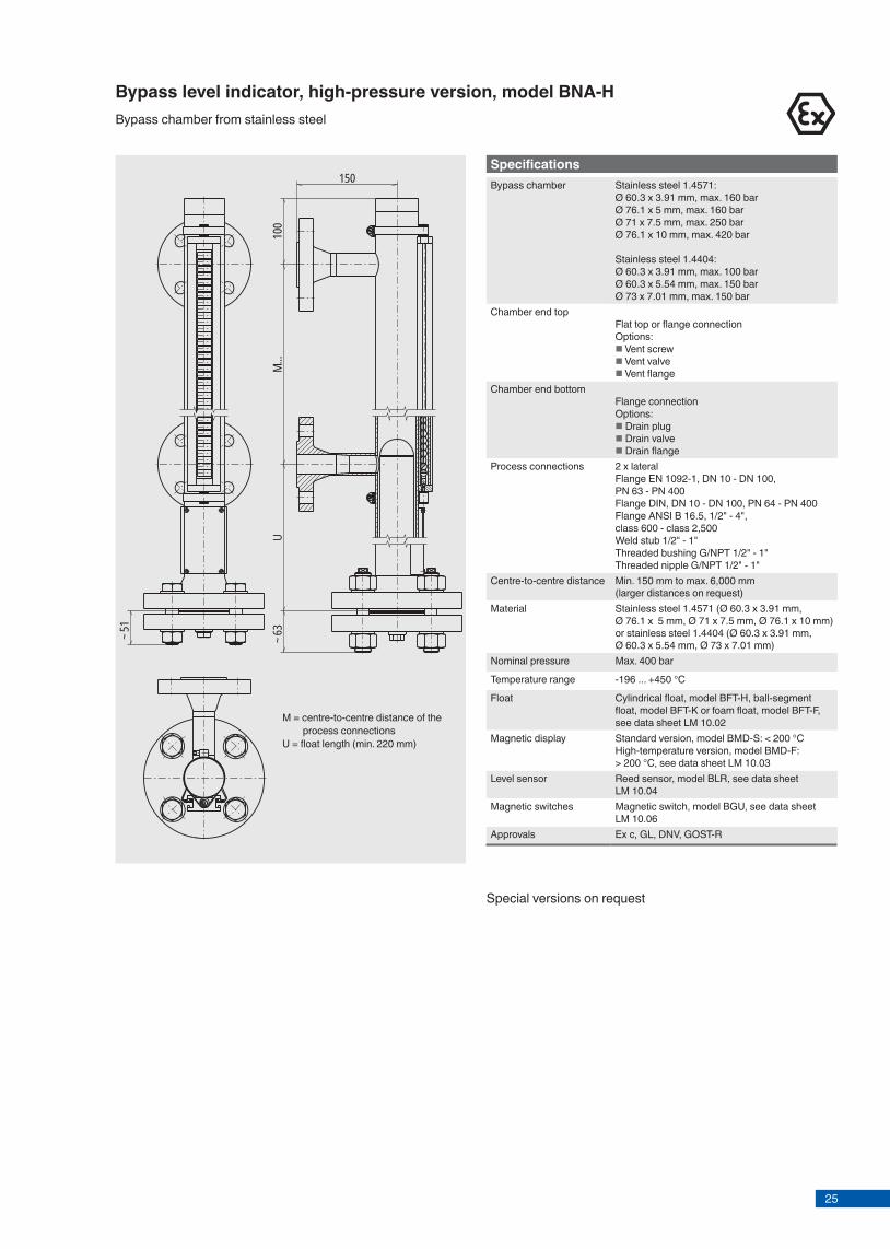
Bypass level indicator, high-pressure version, model BNA-HBypass chamber from stainless steel
150
UM.
..10
0~6
3
~51
Page 5 of 11KSR data sheet BNA for NPP ∙ 04/2015
M = centre-to-centre distance of the process connections
U = float length (min. 220 mm)
SpecificationsBypass chamber Stainless steel 1.4571:
Ø 60.3 x 3.91 mm, max. 160 barØ 76.1 x 5 mm, max. 160 barØ 71 x 7.5 mm, max. 250 barØ 76.1 x 10 mm, max. 420 bar
Stainless steel 1.4404:Ø 60.3 x 3.91 mm, max. 100 barØ 60.3 x 5.54 mm, max. 150 barØ 73 x 7.01 mm, max. 150 bar
Chamber end topFlat top or flange connectionOptions: Vent screw Vent valve Vent flange
Chamber end bottomFlange connectionOptions: Drain plug Drain valve Drain flange
Process connections 2 x lateralFlange EN 1092-1, DN 10 - DN 100, PN 63 - PN 400Flange DIN, DN 10 - DN 100, PN 64 - PN 400Flange ANSI B 16.5, 1/2" - 4", class 600 - class 2,500Weld stub 1/2" - 1"Threaded bushing G/NPT 1/2" - 1"Threaded nipple G/NPT 1/2" - 1"
Centre-to-centre distance Min. 150 mm to max. 6,000 mm (larger distances on request)
Material Stainless steel 1.4571 (Ø 60.3 x 3.91 mm, Ø 76.1 x 5 mm, Ø 71 x 7.5 mm, Ø 76.1 x 10 mm) or stainless steel 1.4404 (Ø 60.3 x 3.91 mm, Ø 60.3 x 5.54 mm, Ø 73 x 7.01 mm)
Nominal pressure Max. 400 bar
Temperature range -196 ... +450 °C
Float Cylindrical float, model BFT-H, ball-segment float, model BFT-K or foam float, model BFT-F, see data sheet LM 10.02
Magnetic display Standard version, model BMD-S: < 200 °CHigh-temperature version, model BMD-F: > 200 °C, see data sheet LM 10.03
Level sensor Reed sensor, model BLR, see data sheet LM 10.04
Magnetic switches Magnetic switch, model BGU, see data sheet LM 10.06
Approvals Ex c, GL, DNV, GOST-R
Special versions on request
25Page 4 of 11 KSR data sheet BNA for NPP ∙ 04/2015
SpecificationsBypass chamber Ø 60.3 x 2 mm, max. 40 bar
Ø 60.3 x 2.77 mm, max. 64 barChamber end top
Flat top or flange connectionOptions: Vent screw Vent valve Vent flange
Chamber end bottomFlange connectionOptions: Drain plug Drain valve Drain flange
Process connections 2 x lateralFlange EN 1092-1, DN 10 - DN 100, PN 6 - PN 63Flange DIN, DN 10 - DN 100, PN 6 - PN 64Flange ANSI B 16.5, 1/2" - 4", class 150 - class 600Weld stub 1/2" - 1"Threaded bushing G/NPT 1/2" - 1"Threaded nipple G/NPT 1/2" - 1"
Centre-to-centre distance Min. 150 mm to max. 6,000 mm (larger distances on request)
Material Stainless steel 1.4571 (316Ti), 1.4404 (316L), 1.4401/1.4404 (316/316L)
Nominal pressure Max. 64 bar
Temperature range -196 ... +450 °C
Float Cylindrical float, model BFT-H or corrugated float, model BFT-S, see data sheet LM 10.02
Magnetic display Standard version, model BMD-S: < 200 °CHigh-temperature version, model BMD-F: > 200 °C, see data sheet LM 10.03
Level sensor Reed sensor, model BLR, see data sheet LM 10.04
Magnetic switches Magnetic switch, model BGU, see data sheet LM 10.06
Approvals Ex c, GL, DNV, ABS, GOST-R, IEEE
Bypass level indicator, standard version, model BNA-SBypass chamber from stainless steel
M = centre-to-centre distance of the process connections
U = float length (min. 200 mm)X = according to process connection
90
X
~35
M...
U
Special versions on request
Bypass level indicator, high-pressure version, model BNA-HBypass chamber from stainless steel
150
UM.
..10
0~6
3
~51
Page 5 of 11KSR data sheet BNA for NPP ∙ 04/2015
M = centre-to-centre distance of the process connections
U = float length (min. 220 mm)
SpecificationsBypass chamber Stainless steel 1.4571:
Ø 60.3 x 3.91 mm, max. 160 barØ 76.1 x 5 mm, max. 160 barØ 71 x 7.5 mm, max. 250 barØ 76.1 x 10 mm, max. 420 bar
Stainless steel 1.4404:Ø 60.3 x 3.91 mm, max. 100 barØ 60.3 x 5.54 mm, max. 150 barØ 73 x 7.01 mm, max. 150 bar
Chamber end topFlat top or flange connectionOptions: Vent screw Vent valve Vent flange
Chamber end bottomFlange connectionOptions: Drain plug Drain valve Drain flange
Process connections 2 x lateralFlange EN 1092-1, DN 10 - DN 100, PN 63 - PN 400Flange DIN, DN 10 - DN 100, PN 64 - PN 400Flange ANSI B 16.5, 1/2" - 4", class 600 - class 2,500Weld stub 1/2" - 1"Threaded bushing G/NPT 1/2" - 1"Threaded nipple G/NPT 1/2" - 1"
Centre-to-centre distance Min. 150 mm to max. 6,000 mm (larger distances on request)
Material Stainless steel 1.4571 (Ø 60.3 x 3.91 mm, Ø 76.1 x 5 mm, Ø 71 x 7.5 mm, Ø 76.1 x 10 mm) or stainless steel 1.4404 (Ø 60.3 x 3.91 mm, Ø 60.3 x 5.54 mm, Ø 73 x 7.01 mm)
Nominal pressure Max. 400 bar
Temperature range -196 ... +450 °C
Float Cylindrical float, model BFT-H, ball-segment float, model BFT-K or foam float, model BFT-F, see data sheet LM 10.02
Magnetic display Standard version, model BMD-S: < 200 °CHigh-temperature version, model BMD-F: > 200 °C, see data sheet LM 10.03
Level sensor Reed sensor, model BLR, see data sheet LM 10.04
Magnetic switches Magnetic switch, model BGU, see data sheet LM 10.06
Approvals Ex c, GL, DNV, GOST-R
Special versions on request

26Page 6 of 11 KSR data sheet BNA for NPP ∙ 04/2015
Bypass level indicator, DUPlus version, standard, model BNA-SDBypass chamber from stainless steel
SpecificationsBypass chamber Ø 60.3 x 2 mm, max. 40 bar
Ø 60.3 x 2.77 mm, max. 64 barChamber end top
Flange connectionOptions: Vent screw Vent valve Vent flange
Chamber end bottomFlat top or flange connectionOptions: Drain plug Drain valve Drain flange
Process connections 2 x lateral Flange DIN, DN 10 - DN 100, PN 6 - PN 64Flange ANSI B 16.5, 1/2" - 4", class 150 - class 600Weld stub 1/2" - 1"Threaded bushing G/NPT 1/2" - 1"Threaded nipple G/NPT 1/2" - 1"
External sensor connection
Flange EN 1092-1, DN 50, PN 6 - PN 64Flange DIN, DN 50, PN 6 - PN 64Flange ANSI B 16.5, 2" class 150 - class 600Female thread G/NPT 3/4" - 2"
Centre-to-centre distance Min. 150 mm to max. 6,000 mm (larger distances on request)
Material Stainless steel 1.4571, 1.4404 or 1.4401/1.4404
Nominal pressure Max. 64 bar
Temperature range -196 ... +450 °C
Float Cylindrical float, model BFT-H or corrugated float, model BFT-S, see data sheet LM 10.02
Magnetic display Standard version, model BMD-S: < 200 °CHigh-temperature version, model BMD-F: > 200 °C, see data sheet LM 10.03
Level sensor Reed sensor, model BLR, see data sheet LM 10.04
Magnetic switches Magnetic switch, model BGU, see data sheet LM 10.06
Approvals Ex c, GOST-R
Special versions on request
Page 7 of 11KSR data sheet BNA for NPP ∙ 04/2015
Bypass level indicator, DUPlus version, high pressure, model BNA-HDBypass chamber from stainless steel
SpecificationsBypass chamber Ø 60.3 x 3.91 mm, max. 160 bar
Chamber end topFlange connectionOptions: Vent screw Vent valve Vent flange
Chamber end bottomFlat top or flange connectionOptions: Drain plug Drain valve Drain flange
Process connections 2 x lateralFlange DIN, DN 10 - DN 100, PN 64 - PN 160Flange ANSI B 16.5, 1/2" - 4", class 600 - class 1,500Weld stub 1/2" - 1"Threaded bushing G/NPT 1/2" - 1"Threaded nipple G/NPT 1/2" - 1"
External sensor connection
Flange EN 1092-1, DN 50, PN 6 - PN 160Flange DIN, DN 50, PN 6 - PN 160Flange ANSI B 16.5, 2" class 150 - class 1,500Female thread G/NPT 3/4" - 2"
Centre-to-centre distance Min. 150 mm to max. 6,000 mm (larger distances on request)
Material Stainless steel 1.4571, 1.4404 or 1.4401/1.4404
Nominal pressure Max. 160 bar
Temperature range -196 ... +450 °C
Float Cylindrical float, model BFT-H, corrugated float, model BFT-S, ball-segment float, model BFT-K or foam float, model BFT-F, see data sheet LM 10.02
Magnetic display Standard version, model BMD-S: < 200 °CHigh-temperature version, model BMD-F: > 200 °C, see data sheet LM 10.03
Level sensor Reed sensor, model BLR, see data sheet LM 10.04
Magnetic switches Magnetic switch, model BGU, see data sheet LM 10.06
Approvals Ex c, GOST-R
Special versions on request

27Page 6 of 11 KSR data sheet BNA for NPP ∙ 04/2015
Bypass level indicator, DUPlus version, standard, model BNA-SDBypass chamber from stainless steel
SpecificationsBypass chamber Ø 60.3 x 2 mm, max. 40 bar
Ø 60.3 x 2.77 mm, max. 64 barChamber end top
Flange connectionOptions: Vent screw Vent valve Vent flange
Chamber end bottomFlat top or flange connectionOptions: Drain plug Drain valve Drain flange
Process connections 2 x lateral Flange DIN, DN 10 - DN 100, PN 6 - PN 64Flange ANSI B 16.5, 1/2" - 4", class 150 - class 600Weld stub 1/2" - 1"Threaded bushing G/NPT 1/2" - 1"Threaded nipple G/NPT 1/2" - 1"
External sensor connection
Flange EN 1092-1, DN 50, PN 6 - PN 64Flange DIN, DN 50, PN 6 - PN 64Flange ANSI B 16.5, 2" class 150 - class 600Female thread G/NPT 3/4" - 2"
Centre-to-centre distance Min. 150 mm to max. 6,000 mm (larger distances on request)
Material Stainless steel 1.4571, 1.4404 or 1.4401/1.4404
Nominal pressure Max. 64 bar
Temperature range -196 ... +450 °C
Float Cylindrical float, model BFT-H or corrugated float, model BFT-S, see data sheet LM 10.02
Magnetic display Standard version, model BMD-S: < 200 °CHigh-temperature version, model BMD-F: > 200 °C, see data sheet LM 10.03
Level sensor Reed sensor, model BLR, see data sheet LM 10.04
Magnetic switches Magnetic switch, model BGU, see data sheet LM 10.06
Approvals Ex c, GOST-R
Special versions on request
Page 7 of 11KSR data sheet BNA for NPP ∙ 04/2015
Bypass level indicator, DUPlus version, high pressure, model BNA-HDBypass chamber from stainless steel
SpecificationsBypass chamber Ø 60.3 x 3.91 mm, max. 160 bar
Chamber end topFlange connectionOptions: Vent screw Vent valve Vent flange
Chamber end bottomFlat top or flange connectionOptions: Drain plug Drain valve Drain flange
Process connections 2 x lateralFlange DIN, DN 10 - DN 100, PN 64 - PN 160Flange ANSI B 16.5, 1/2" - 4", class 600 - class 1,500Weld stub 1/2" - 1"Threaded bushing G/NPT 1/2" - 1"Threaded nipple G/NPT 1/2" - 1"
External sensor connection
Flange EN 1092-1, DN 50, PN 6 - PN 160Flange DIN, DN 50, PN 6 - PN 160Flange ANSI B 16.5, 2" class 150 - class 1,500Female thread G/NPT 3/4" - 2"
Centre-to-centre distance Min. 150 mm to max. 6,000 mm (larger distances on request)
Material Stainless steel 1.4571, 1.4404 or 1.4401/1.4404
Nominal pressure Max. 160 bar
Temperature range -196 ... +450 °C
Float Cylindrical float, model BFT-H, corrugated float, model BFT-S, ball-segment float, model BFT-K or foam float, model BFT-F, see data sheet LM 10.02
Magnetic display Standard version, model BMD-S: < 200 °CHigh-temperature version, model BMD-F: > 200 °C, see data sheet LM 10.03
Level sensor Reed sensor, model BLR, see data sheet LM 10.04
Magnetic switches Magnetic switch, model BGU, see data sheet LM 10.06
Approvals Ex c, GOST-R
Special versions on request

28Page 8 of 11 KSR data sheet BNA for NPP ∙ 04/2015
SpecificationsMaterial 1) Hastelloy C276 Stainless steel 6Mo 1.4547
(UNS S31254)Bypass chamber Ø 60.3 x 2.77 mm, max. 64
barØ 60.3 x 3.91 mm, max. 160 bar
Ø 60.3 x 2.77 mm, max. 64 barØ 60.3 x 3.91 mm, max. 160 barØ 60.3 x 5.54 mm, max. 250 bar
Chamber end top
Chamber end bottom
Process connections(2 x lateral, options see page 15)
Flange EN 1092-1, DN 10 - DN 100, PN 6 - PN 400Flange DIN, DN 10 - DN 100, PN 6 - PN 400Flange ANSI B 16.5, 1/2" - 4", class 150 - class 2,500
Flange EN 1092-1, DN 10 - DN 100, PN 63 - PN 400Flange DIN, DN 10 - DN 100, PN 64 - PN 400Flange ANSI B 16.5, 1/2" - 4", class 600 - class 2,500
Centre-to-centre distanceNominal pressure Max. 160 bar Max. 250 bar
Temperature range
Float
Magnetic display
Level sensor
Magnetic switches
Approvals Ex c, GL, DNV, GOST-R Ex c, GOST-R
Bypass level indicator, special materials, model BNA-XBypass chamber from Titanium, Hastelloy or stainless steel 6Mo
150
UM.
..10
0~6
3
~51
M = centre-to-centre distance of the process connections
U = float length (min. 220 mm)
1) Other materials on request
Special versions on request
Page 9 of 11KSR data sheet BNA for NPP ∙ 04/2015
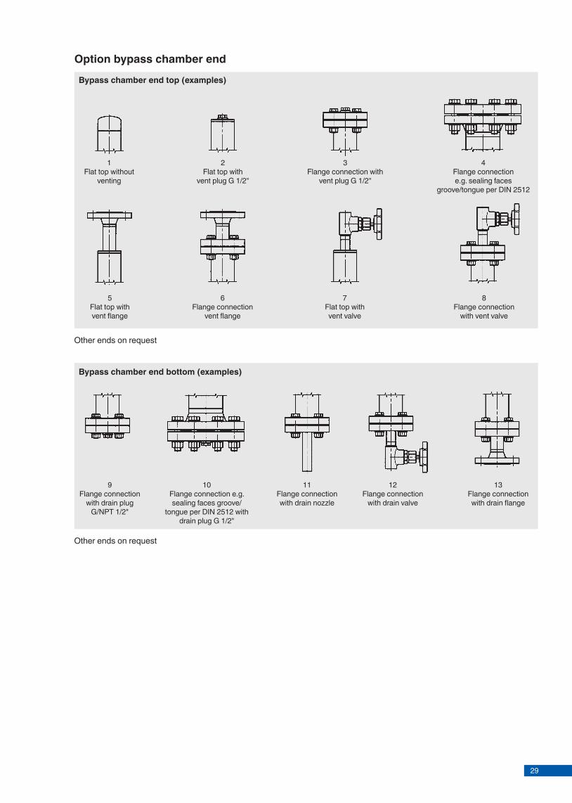
Bypass chamber end top (examples)
1Flat top without
venting
Bypass chamber end bottom (examples)
2Flat top with
vent plug G 1/2"
3Flange connection with
vent plug G 1/2"
4Flange connectione.g. sealing faces
groove/tongue per DIN 2512
5Flat top withvent flange
6Flange connection
vent flange
7Flat top with vent valve
8Flange connection
with vent valve
9Flange connection
with drain plug G/NPT 1/2"
10Flange connection e.g. sealing faces groove/
tongue per DIN 2512 with drain plug G 1/2"
11Flange connection with drain nozzle
12Flange connection
with drain valve
13Flange connection with drain flange
Option bypass chamber end
Other ends on request
Other ends on request
29Page 8 of 11 KSR data sheet BNA for NPP ∙ 04/2015
SpecificationsMaterial 1) Hastelloy C276 Stainless steel 6Mo 1.4547
(UNS S31254)Bypass chamber Ø 60.3 x 2.77 mm, max. 64
barØ 60.3 x 3.91 mm, max. 160 bar
Ø 60.3 x 2.77 mm, max. 64 barØ 60.3 x 3.91 mm, max. 160 barØ 60.3 x 5.54 mm, max. 250 bar
Chamber end top
Chamber end bottom
Process connections(2 x lateral, options see page 15)
Flange EN 1092-1, DN 10 - DN 100, PN 6 - PN 400Flange DIN, DN 10 - DN 100, PN 6 - PN 400Flange ANSI B 16.5, 1/2" - 4", class 150 - class 2,500
Flange EN 1092-1, DN 10 - DN 100, PN 63 - PN 400Flange DIN, DN 10 - DN 100, PN 64 - PN 400Flange ANSI B 16.5, 1/2" - 4", class 600 - class 2,500
Centre-to-centre distanceNominal pressure Max. 160 bar Max. 250 bar
Temperature range
Float
Magnetic display
Level sensor
Magnetic switches
Approvals Ex c, GL, DNV, GOST-R Ex c, GOST-R
Bypass level indicator, special materials, model BNA-XBypass chamber from Titanium, Hastelloy or stainless steel 6Mo
150
UM.
..10
0~6
3
~51
M = centre-to-centre distance of the process connections
U = float length (min. 220 mm)
1) Other materials on request
Special versions on request
Page 9 of 11KSR data sheet BNA for NPP ∙ 04/2015
Bypass chamber end top (examples)
1Flat top without
venting
Bypass chamber end bottom (examples)
2Flat top with
vent plug G 1/2"
3Flange connection with
vent plug G 1/2"
4Flange connectione.g. sealing faces
groove/tongue per DIN 2512
5Flat top withvent flange
6Flange connection
vent flange
7Flat top with vent valve
8Flange connection
with vent valve
9Flange connection
with drain plug G/NPT 1/2"
10Flange connection e.g. sealing faces groove/
tongue per DIN 2512 with drain plug G 1/2"
11Flange connection with drain nozzle
12Flange connection
with drain valve
13Flange connection with drain flange
Option bypass chamber end
Other ends on request
Other ends on request

30Page 10 of 11 KSR data sheet BNA for NPP ∙ 04/2015
14Welding neck flange
up to DN 25
15Blind flange
above DN 32
16Threaded coupling GN ... (male thread)
17Threaded coupling
GM ... (female thread)
18Weld stub S ...
201 process connection lateral 1 process connection vertical
(top)
212 process connections
to DIN 11851 Lower process connection via
eccentric reducer
222 process connections
vertical (top/bottom)Option: Support bracket
19Standard version
Process connections 2 x lateral
Option process connection
Examples
Other connections on request
KSR KUEBLER Niveau-Messtechnik AGHeinrich-Kuebler-Platz 169439 Zwingenberg/GermanyTel. +49 6263 87-0Fax +49 6263 [email protected]
CE conformity
Pressure equipment directive97/23/EC, pressure accessory
ATEX directive (option)94/9/EC, ignition protection type Ex c, zone 0/1, gas
Approvals
■ GL, ships, shipbuilding, off shore, Germany ■ DNV, ships, shipbuilding, off shore, Norway ■ ABS, ships, shipbuilding, off shore, USA ■ GOST, national standard for Russia, Kazakhstan and
Belarus ■ IEEE 344, standard for seismic qualifi cation of equipment
for nuclear power generating stationsApprovals and certifi cates, see website
© 2014 KSR KUEBLER Niveau-Messtechnik AG, all rights reserved.The specifi cations given in this document represent the state of engineering at the time of publishing.We reserve the right to make modifi cations to the specifi cations and materials.
KSR data sheet BNA for NPP ∙ 04/2015Page 11 of 11
04/2
015
EN

31Page 10 of 11 KSR data sheet BNA for NPP ∙ 04/2015
14Welding neck flange
up to DN 25
15Blind flange
above DN 32
16Threaded coupling GN ... (male thread)
17Threaded coupling
GM ... (female thread)
18Weld stub S ...
201 process connection lateral 1 process connection vertical
(top)
212 process connections
to DIN 11851 Lower process connection via
eccentric reducer
222 process connections
vertical (top/bottom)Option: Support bracket
19Standard version
Process connections 2 x lateral
Option process connection
Examples
Other connections on request
KSR KUEBLER Niveau-Messtechnik AGHeinrich-Kuebler-Platz 169439 Zwingenberg/GermanyTel. +49 6263 87-0Fax +49 6263 [email protected]
CE conformity
Pressure equipment directive97/23/EC, pressure accessory
ATEX directive (option)94/9/EC, ignition protection type Ex c, zone 0/1, gas
Approvals
■ GL, ships, shipbuilding, off shore, Germany ■ DNV, ships, shipbuilding, off shore, Norway ■ ABS, ships, shipbuilding, off shore, USA ■ GOST, national standard for Russia, Kazakhstan and
Belarus ■ IEEE 344, standard for seismic qualifi cation of equipment
for nuclear power generating stationsApprovals and certifi cates, see website
© 2014 KSR KUEBLER Niveau-Messtechnik AG, all rights reserved.The specifi cations given in this document represent the state of engineering at the time of publishing.We reserve the right to make modifi cations to the specifi cations and materials.
KSR data sheet BNA for NPP ∙ 04/2015Page 11 of 11
04/2
015
EN
32
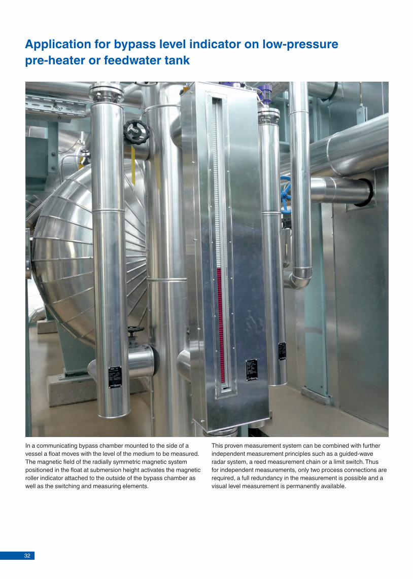
Application for bypass level indicator on low-pressure pre-heater or feedwater tank
In a communicating bypass chamber mounted to the side of a vessel a float moves with the level of the medium to be measured. The magnetic field of the radially symmetric magnetic system positioned in the float at submersion height activates the magnetic roller indicator attached to the outside of the bypass chamber as well as the switching and measuring elements.
This proven measurement system can be combined with further independent measurement principles such as a guided-wave radar system, a reed measurement chain or a limit switch. Thus for independent measurements, only two process connections are required, a full redundancy in the measurement is possible and a visual level measurement is permanently available.
FloatFor bypass level indicatorsModel BFT for nuclear power plants
Applications
■ Float for the monitoring of liquids in bypass level indicators ■ Individual design and corrosion resistant materials make
the products suitable for a broad range of applications ■ Chemical, petrochemical, natural gas, off shore,
shipbuilding, machine building, power generating equipment, power plants
■ Process water and drinking water treatment, food industry, pharmaceutical industry
Special features
■ Sealed, pressure retaining design ■ Density range from 340 kg/m³ ■ Pressures up to 400 bar ■ Medium temperatures from -196 ... +450 °C ■ Versions for interface layer
Description
The model BFT fl oat serves for the monitoring of liquids in bypass level indicators. The magnetic system built into the fl oat transmits the liquid level, contact-free, to externally mounted displays, switches and sensors. Due to its omni-directional, radial magnetic fi eld, a guide within the tube is not needed.
The design will depend on the application, chemical resist-ance and the 3 physical quantities of pressure, temperature and density.
Level measurement
KSR data sheet BFT for NPP
Page 1 of 3KSR data sheet BFT for NPP ∙ 04/2015
Fig. left: Corrugated fl oat, model BFT-SFig. centre: Cylindrical fl oat, model BFT-HFig. right: Ball-segment fl oat, model BFT-K

33
FloatFor bypass level indicatorsModel BFT for nuclear power plants
Applications
■ Float for the monitoring of liquids in bypass level indicators ■ Individual design and corrosion resistant materials make
the products suitable for a broad range of applications ■ Chemical, petrochemical, natural gas, off shore,
shipbuilding, machine building, power generating equipment, power plants
■ Process water and drinking water treatment, food industry, pharmaceutical industry
Special features
■ Sealed, pressure retaining design ■ Density range from 340 kg/m³ ■ Pressures up to 400 bar ■ Medium temperatures from -196 ... +450 °C ■ Versions for interface layer
Description
The model BFT fl oat serves for the monitoring of liquids in bypass level indicators. The magnetic system built into the fl oat transmits the liquid level, contact-free, to externally mounted displays, switches and sensors. Due to its omni-directional, radial magnetic fi eld, a guide within the tube is not needed.
The design will depend on the application, chemical resist-ance and the 3 physical quantities of pressure, temperature and density.
Level measurement
KSR data sheet BFT for NPP
Page 1 of 3KSR data sheet BFT for NPP ∙ 04/2015
Fig. left: Corrugated fl oat, model BFT-SFig. centre: Cylindrical fl oat, model BFT-HFig. right: Ball-segment fl oat, model BFT-K

34
Model overviewFloat Material Density range Pressure range Temperature rangeCylindrical float, model BFT-H
Stainless steel 1.4571 > 470 kg/m³ Vacuum ... 100 bar -200 ... +450 °CTitanium 3.7035 > 340 kg/m³
Corrugated float, model BFT-S
Stainless steel 1.4571 > 470 kg/m³ Vacuum ... 25 bar -50 ... +200 °CTitanium 3.7035 > 340 kg/m³
Ball-segment float, model BFT-K
Titanium 3.7065 > 400 kg/m³ Vacuum ... 250 bar -200 ... +450 °C
Classification of the floatsBypass level indicator Suitable float
Model BFT-S Model BFT-H Model BFT-KStandard version, model BNA-S x xHigh-pressure version, model BNA-H x xDUPlus version, model BNA-SD x x
Page 2 of 3 KSR data sheet BFT for NPP ∙ 04/2015
Corrugated float, model BFT-S50 Permissible temperature: -50 ... +200 °C
PN Density range in kg/m³
Diameter in mm
Length in mm
Material
25 990 ... 2,000 50 150 Stainless steel (1.4571)830 ... 1,000 50 185 Stainless steel (1.4571)730 ... 840 50 225 Stainless steel (1.4571)640 ... 730 50 275 Stainless steel (1.4571)590 ... 650 50 335 Stainless steel (1.4571)550 ... 600 50 400 Stainless steel (1.4571)520 ... 560 50 470 Stainless steel (1.4571)490 ... 530 50 555 Stainless steel (1.4571)470 ... 500 50 650 Stainless steel (1.4571)820 ... 2,000 50.8 150 Titanium (3.7035)710 ... 850 50.8 180 Titanium (3.7035)600 ... 710 50.8 215 Titanium (3.7035)540 ... 610 50.8 250 Titanium (3.7035)480 ... 540 50.8 300 Titanium (3.7035)430 ... 490 50.8 355 Titanium (3.7035)400 ... 440 50.8 410 Titanium (3.7035)380 ... 410 50.8 465 Titanium (3.7035)370 ... 390 50.8 525 Titanium (3.7035)360 ... 380 50.8 595 Titanium (3.7035)340 ... 370 50.8 680 Titanium (3.7035)
KSR KUEBLER Niveau-Messtechnik AGHeinrich-Kuebler-Platz 169439 Zwingenberg/GermanyTel. +49 6263 87-0Fax +49 6263 [email protected]
© 2014 KSR KUEBLER Niveau-Messtechnik AG, all rights reserved.The specifications given in this document represent the state of engineering at the time of publishing.We reserve the right to make modifications to the specifications and materials.
Page 3 of 3KSR data sheet BFT for NPP∙ 04/2015
04/2
015
EN
Cylindrical fl oat, model BFT-HPermissible temperature: -200 ... +450 °C
Material: Stainless steel 1.4571Diameter: 50 mmLength: 150 ... 650 mm (depending on pressure, density and
temperature)Weight: depending on pressure, density and temperatureMagnetic system: depending on pressure, density and temperatureNominal density: depending on pressure, density and temperatureDensity range: depending on pressure, density and temperatureMax. pressure: < 40 bar
Material: Titanium 3.7035Diameter: 45, 50.8 or 60 mmLength: 150 ... 650 mm (depending on pressure, density and
temperature)Weight: depending on pressure, density and temperatureMagnetic system: depending on pressure, density and temperatureNominal density: depending on pressure, density and temperatureDensity range: depending on pressure, density and temperatureMax. pressure: < 100 bar
Ball-segment fl oat, model BFT-KPermissible temperature: -200 ... +450 °C
Material: Titanium 3.7065Diameter: 45, 50.8 or 60 mmLength: 150 ... 700 mm (depending on pressure, density and
temperature)Weight: depending on pressure, density and temperatureMagnetic system: depending on pressure, density and temperatureNominal density: depending on pressure, density and temperatureDensity range: depending on pressure, density and temperatureMax. pressure: < 250 bar
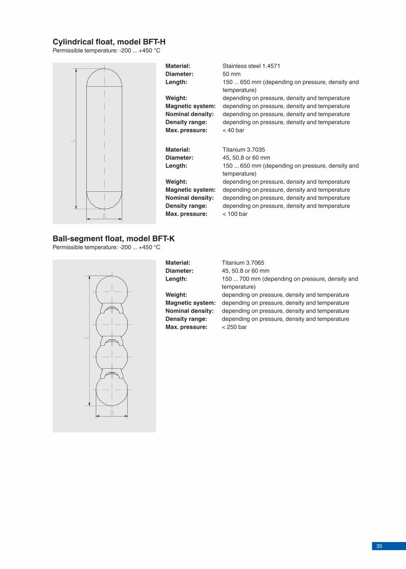
35
Model overviewFloat Material Density range Pressure range Temperature rangeCylindrical float, model BFT-H
Stainless steel 1.4571 > 470 kg/m³ Vacuum ... 100 bar -200 ... +450 °CTitanium 3.7035 > 340 kg/m³
Corrugated float, model BFT-S
Stainless steel 1.4571 > 470 kg/m³ Vacuum ... 25 bar -50 ... +200 °CTitanium 3.7035 > 340 kg/m³
Ball-segment float, model BFT-K
Titanium 3.7065 > 400 kg/m³ Vacuum ... 250 bar -200 ... +450 °C
Classification of the floatsBypass level indicator Suitable float
Model BFT-S Model BFT-H Model BFT-KStandard version, model BNA-S x xHigh-pressure version, model BNA-H x xDUPlus version, model BNA-SD x x
Page 2 of 3 KSR data sheet BFT for NPP ∙ 04/2015
Corrugated float, model BFT-S50 Permissible temperature: -50 ... +200 °C
PN Density range in kg/m³
Diameter in mm
Length in mm
Material
25 990 ... 2,000 50 150 Stainless steel (1.4571)830 ... 1,000 50 185 Stainless steel (1.4571)730 ... 840 50 225 Stainless steel (1.4571)640 ... 730 50 275 Stainless steel (1.4571)590 ... 650 50 335 Stainless steel (1.4571)550 ... 600 50 400 Stainless steel (1.4571)520 ... 560 50 470 Stainless steel (1.4571)490 ... 530 50 555 Stainless steel (1.4571)470 ... 500 50 650 Stainless steel (1.4571)820 ... 2,000 50.8 150 Titanium (3.7035)710 ... 850 50.8 180 Titanium (3.7035)600 ... 710 50.8 215 Titanium (3.7035)540 ... 610 50.8 250 Titanium (3.7035)480 ... 540 50.8 300 Titanium (3.7035)430 ... 490 50.8 355 Titanium (3.7035)400 ... 440 50.8 410 Titanium (3.7035)380 ... 410 50.8 465 Titanium (3.7035)370 ... 390 50.8 525 Titanium (3.7035)360 ... 380 50.8 595 Titanium (3.7035)340 ... 370 50.8 680 Titanium (3.7035)
KSR KUEBLER Niveau-Messtechnik AGHeinrich-Kuebler-Platz 169439 Zwingenberg/GermanyTel. +49 6263 87-0Fax +49 6263 [email protected]
© 2014 KSR KUEBLER Niveau-Messtechnik AG, all rights reserved.The specifications given in this document represent the state of engineering at the time of publishing.We reserve the right to make modifications to the specifications and materials.
Page 3 of 3KSR data sheet BFT for NPP∙ 04/2015
04/2
015
EN
Cylindrical fl oat, model BFT-HPermissible temperature: -200 ... +450 °C
Material: Stainless steel 1.4571Diameter: 50 mmLength: 150 ... 650 mm (depending on pressure, density and
temperature)Weight: depending on pressure, density and temperatureMagnetic system: depending on pressure, density and temperatureNominal density: depending on pressure, density and temperatureDensity range: depending on pressure, density and temperatureMax. pressure: < 40 bar
Material: Titanium 3.7035Diameter: 45, 50.8 or 60 mmLength: 150 ... 650 mm (depending on pressure, density and
temperature)Weight: depending on pressure, density and temperatureMagnetic system: depending on pressure, density and temperatureNominal density: depending on pressure, density and temperatureDensity range: depending on pressure, density and temperatureMax. pressure: < 100 bar
Ball-segment fl oat, model BFT-KPermissible temperature: -200 ... +450 °C
Material: Titanium 3.7065Diameter: 45, 50.8 or 60 mmLength: 150 ... 700 mm (depending on pressure, density and
temperature)Weight: depending on pressure, density and temperatureMagnetic system: depending on pressure, density and temperatureNominal density: depending on pressure, density and temperatureDensity range: depending on pressure, density and temperatureMax. pressure: < 250 bar

36
Magnetic displayFor bypass level indicatorsModel BMD for nuclear power plants
Magnetic displayFig. left: Plastic rollers, model BMD-SAFig. right: Stainless steel fl aps, model BMD-FR
Applications
■ Display bar for the visualisation of levels in combination with bypass level indicators
■ Individual design and corrosion resistant materials make the products suitable for a broad range of applications
■ Chemical, petrochemical, natural gas, off shore, shipbuilding, machine building, power generating equipment, power plants
■ Process water and drinking water treatment, food industry, pharmaceutical industry
Special features
■ Measured value display by means of rollers or fl aps with permanent magnets
■ Medium temperatures from -200 ... +450 °C ■ Splash-proof ■ Without power supply ■ Hermetically sealed from the process
Description
The model BMD magnetic displays are used in combination with bypass level indicators for the display of levels. A magnetic system built into the fl oat transmits the liquid level, contact-free, to the externally mounted display. In this are fi tted, at 10 mm intervals, red/white plastic rollers or stainless steel fl aps with bar magnets. Through the directional magnetic fi eld of the permanent magnetic system in the bypass fl oat, the magnetic rollers or fl aps, through the wall of the bypass chamber, are turned through 180°.For an increasing level from white to red; for a falling level from red to white. Thus the magnetic display indicates the level of a vessel as a red column, without power supply.
Level measurement
An integrated T-slot serves for the fastening of further attachment parts such as scales, sensors and switches.
For selecting the optimum magnetic display (plastic rollers/stainless steel fl aps, case, scale, measuring range etc.) we off er application-related technical advice.
KSR data sheet BMD for NPP
Page 1 of 5KSR data sheet BMD for NPP ∙ 04/2015

37
Magnetic displayFor bypass level indicatorsModel BMD for nuclear power plants
Magnetic displayFig. left: Plastic rollers, model BMD-SAFig. right: Stainless steel fl aps, model BMD-FR
Applications
■ Display bar for the visualisation of levels in combination with bypass level indicators
■ Individual design and corrosion resistant materials make the products suitable for a broad range of applications
■ Chemical, petrochemical, natural gas, off shore, shipbuilding, machine building, power generating equipment, power plants
■ Process water and drinking water treatment, food industry, pharmaceutical industry
Special features
■ Measured value display by means of rollers or fl aps with permanent magnets
■ Medium temperatures from -200 ... +450 °C ■ Splash-proof ■ Without power supply ■ Hermetically sealed from the process
Description
The model BMD magnetic displays are used in combination with bypass level indicators for the display of levels. A magnetic system built into the fl oat transmits the liquid level, contact-free, to the externally mounted display. In this are fi tted, at 10 mm intervals, red/white plastic rollers or stainless steel fl aps with bar magnets. Through the directional magnetic fi eld of the permanent magnetic system in the bypass fl oat, the magnetic rollers or fl aps, through the wall of the bypass chamber, are turned through 180°.For an increasing level from white to red; for a falling level from red to white. Thus the magnetic display indicates the level of a vessel as a red column, without power supply.
Level measurement
An integrated T-slot serves for the fastening of further attachment parts such as scales, sensors and switches.
For selecting the optimum magnetic display (plastic rollers/stainless steel fl aps, case, scale, measuring range etc.) we off er application-related technical advice.
KSR data sheet BMD for NPP
Page 1 of 5KSR data sheet BMD for NPP ∙ 04/2015

38
Model overviewMagnetic display model
Description
BMD-SA Plastic rollers in aluminium case, with T-slot
BMD-SR Plastic rollers in stainless steel case with T-slot
BMD-FA Stainless steel flaps in aluminium case, with T-slot
BMD-FR Stainless steel flaps in stainless steel case with T-slot
Options
■ Scale with adhesive foil ■ Scale engraved aluminium ■ Scale engraved stainless steel ■ Scale in cm, mm or % ■ Special scale ■ Acrylic sight glass extender for insulation at low
temperatures ■ Purge gas connection ■ Display elements in the colours red, white, black and
yellow (others on request)
Page 2 of 5 KSR data sheet BMD for NPP ∙ 04/2015
M = measuring range (increment 40 mm)L = M + 80
L =
... M
= ..
.
49
23
Magnetic display, plastic rollers in aluminium case, with T-slot, BMD-SAPermissible temperature: -50 ... +200 °C
SpecificationsCase Aluminium, anodisedLength L 180 ... 6,000 mmDisplay element Plastic rollers, PBT, red/whiteIndicator window Polycarbonate
Magnetic display, plastic rollers in stainless steel case, with T-slot, BMD-SRPermissible temperature: -50 ... +200 °C
SpecificationsCase Stainless steelLength L 180 ... 6,000 mmDisplay element Plastic rollers, PBT, red/whiteIndicator window Polycarbonate
Page 3 of 5KSR data sheet BMD for NPP ∙ 04/2015
M = measuring range (increment 40 mm)L = M + 80

39
Model overviewMagnetic display model
Description
BMD-SA Plastic rollers in aluminium case, with T-slot
BMD-SR Plastic rollers in stainless steel case with T-slot
BMD-FA Stainless steel flaps in aluminium case, with T-slot
BMD-FR Stainless steel flaps in stainless steel case with T-slot
Options
■ Scale with adhesive foil ■ Scale engraved aluminium ■ Scale engraved stainless steel ■ Scale in cm, mm or % ■ Special scale ■ Acrylic sight glass extender for insulation at low
temperatures ■ Purge gas connection ■ Display elements in the colours red, white, black and
yellow (others on request)
Page 2 of 5 KSR data sheet BMD for NPP ∙ 04/2015
M = measuring range (increment 40 mm)L = M + 80
L =
... M
= ..
.
49
23
Magnetic display, plastic rollers in aluminium case, with T-slot, BMD-SAPermissible temperature: -50 ... +200 °C
SpecificationsCase Aluminium, anodisedLength L 180 ... 6,000 mmDisplay element Plastic rollers, PBT, red/whiteIndicator window Polycarbonate
Magnetic display, plastic rollers in stainless steel case, with T-slot, BMD-SRPermissible temperature: -50 ... +200 °C
SpecificationsCase Stainless steelLength L 180 ... 6,000 mmDisplay element Plastic rollers, PBT, red/whiteIndicator window Polycarbonate
Page 3 of 5KSR data sheet BMD for NPP ∙ 04/2015
M = measuring range (increment 40 mm)L = M + 80

40
L =
... M
= ..
.
49
23
Magnetic display, stainless steel flaps in stainless steel case, with T-slot, BMD-FRPermissible temperature: -200 ... +450 °C
SpecificationsCase Stainless steelLength L 180 ... 6,000 mmDisplay element Stainless steel flaps, red/whiteIndicator window Glass
Magnetic display, stainless steel flaps in aluminium case, with T-slot, BMD-FAPermissible temperature: -200 ... +450 °C
SpecificationsCase Aluminium, anodisedLength L 180 ... 6,000 mmDisplay element Stainless steel flaps, red/whiteIndicator window Glass
Page 4 of 5 KSR data sheet BMD for NPP ∙ 04/2015
M = measuring range (increment 40 mm)L = M + 80
M = measuring range (increment 40 mm)L = M + 80
L ...
M ..
.23
4940
KSR KUEBLER Niveau-Messtechnik AGHeinrich-Kuebler-Platz 169439 Zwingenberg/GermanyTel. +49 6263 87-0Fax +49 6263 [email protected]
© 2014 KSR KUEBLER Niveau-Messtechnik AG, all rights reserved.The specifi cations given in this document represent the state of engineering at the time of publishing.We reserve the right to make modifi cations to the specifi cations and materials.
Scale (adhesive foil, aluminium or stainless steel)Aluminium with adhesive foil, cm-graduationmax. ambient temperature for the adhesive foil: 100 °CAluminium or stainless steel engraved, graduation selectable
Option
Page 5 of 5KSR data sheet BMD for NPP∙ 04/2015
04/2
015
EN

41
L =
... M
= ..
.
49
23
Magnetic display, stainless steel flaps in stainless steel case, with T-slot, BMD-FRPermissible temperature: -200 ... +450 °C
SpecificationsCase Stainless steelLength L 180 ... 6,000 mmDisplay element Stainless steel flaps, red/whiteIndicator window Glass
Magnetic display, stainless steel flaps in aluminium case, with T-slot, BMD-FAPermissible temperature: -200 ... +450 °C
SpecificationsCase Aluminium, anodisedLength L 180 ... 6,000 mmDisplay element Stainless steel flaps, red/whiteIndicator window Glass
Page 4 of 5 KSR data sheet BMD for NPP ∙ 04/2015
M = measuring range (increment 40 mm)L = M + 80
M = measuring range (increment 40 mm)L = M + 80
L ...
M ..
.23
4940
KSR KUEBLER Niveau-Messtechnik AGHeinrich-Kuebler-Platz 169439 Zwingenberg/GermanyTel. +49 6263 87-0Fax +49 6263 [email protected]
© 2014 KSR KUEBLER Niveau-Messtechnik AG, all rights reserved.The specifi cations given in this document represent the state of engineering at the time of publishing.We reserve the right to make modifi cations to the specifi cations and materials.
Scale (adhesive foil, aluminium or stainless steel)Aluminium with adhesive foil, cm-graduationmax. ambient temperature for the adhesive foil: 100 °CAluminium or stainless steel engraved, graduation selectable
Option
Page 5 of 5KSR data sheet BMD for NPP∙ 04/2015
04/2
015
EN

42
Reed sensorFor bypass level indicatorsModel BLR for nuclear power plants
Reed sensor, model BLR-S
Applications
■ Sensor for continuous level measurement of liquids in bypass level indicators
■ Chemical and petrochemical industries, oil and natural gas extraction (on- and off shore)
■ Shipbuilding, machine building ■ Power generating equipment, power plants ■ Pharmaceutical, food, water treatment, environmental
engineering industries
Special features
■ Installation of head-mounted transmitters in the connection housing possible
■ Various contact separations selectable ■ Programmable and confi gurable head-mounted
transmitters for fi eld signal 4 ... 20 mA, HART®, PROFIBUS® PA or FOUNDATION™ Fieldbus
■ Explosion-protected versions ■ Temperature ranges from -100 … +350 °C
Description
The model BLR reed sensors are used for continuous monitoring and recording of the liquid level in connection with transmitters. They work on the fl oat principle with magnetic transmission (permanent magnet, reed switch and resistance measuring chain) in a 3-wire potentiometer circuit.
A magnetic system built into the fl oat actuates, through the walls of the bypass chamber and of the sensor tube, reed contacts at a resistance measuring chain (potentiometer). The measurement voltage generated by this is proportional to the fi ll level.
Level measurement
The resistance measuring chain is made up from reed contacts and resistors soldered onto a PCB. Depending on requirements and design several diff erent contact separations from 5 to 18 mm are available.For selecting the optimum sensor (sensor model, connection housing, electrical connection, sensor tube (material and total length), contact separation, head-mounted transmitter, measuring range, approval) we off er application-related technical advice.
KSR data sheet BLR for NPP
Page 1 of 4KSR data sheet BLR for NPP ∙ 04/2015
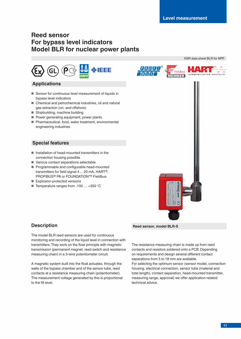
43
Reed sensorFor bypass level indicatorsModel BLR for nuclear power plants
Reed sensor, model BLR-S
Applications
■ Sensor for continuous level measurement of liquids in bypass level indicators
■ Chemical and petrochemical industries, oil and natural gas extraction (on- and off shore)
■ Shipbuilding, machine building ■ Power generating equipment, power plants ■ Pharmaceutical, food, water treatment, environmental
engineering industries
Special features
■ Installation of head-mounted transmitters in the connection housing possible
■ Various contact separations selectable ■ Programmable and confi gurable head-mounted
transmitters for fi eld signal 4 ... 20 mA, HART®, PROFIBUS® PA or FOUNDATION™ Fieldbus
■ Explosion-protected versions ■ Temperature ranges from -100 … +350 °C
Description
The model BLR reed sensors are used for continuous monitoring and recording of the liquid level in connection with transmitters. They work on the fl oat principle with magnetic transmission (permanent magnet, reed switch and resistance measuring chain) in a 3-wire potentiometer circuit.
A magnetic system built into the fl oat actuates, through the walls of the bypass chamber and of the sensor tube, reed contacts at a resistance measuring chain (potentiometer). The measurement voltage generated by this is proportional to the fi ll level.
Level measurement
The resistance measuring chain is made up from reed contacts and resistors soldered onto a PCB. Depending on requirements and design several diff erent contact separations from 5 to 18 mm are available.For selecting the optimum sensor (sensor model, connection housing, electrical connection, sensor tube (material and total length), contact separation, head-mounted transmitter, measuring range, approval) we off er application-related technical advice.
KSR data sheet BLR for NPP
Page 1 of 4KSR data sheet BLR for NPP ∙ 04/2015
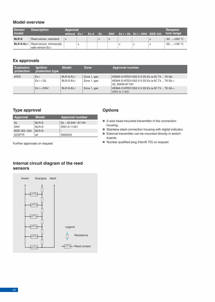
44
Model overviewSensor model
Description Approval Tempera-ture rangewithout Ex i Ex d GL DNV Ex i + GL Ex i + DNV IEEE 323
BLR-S Reed sensor, standard x x x x -50 ... +350 °CBLR-S-Ex i Reed sensor, intrinsically
safe version Ex i x x x x -50 ... +100 °C
Ex approvalsExplosion protection
Ignition protection type
Model Zone Approval number
ATEX Ex i BLR-S-Ex i Zone 1, gas KEMA 01ATEX1052 X II 2G Ex ia IIC T4 ... T6 GbEx i + GL BLR-S-Ex i Zone 1, gas KEMA 01ATEX1052 X II 2G Ex ia IIC T4 ... T6 Gb +
GL 35949-87 HHEx i + DNV BLR-S-Ex i Zone 1, gas KEMA 01ATEX1052 X II 2G Ex ia IIC T4 ... T6 Gb +
DNV A-11451
Type approvalApproval Model Approval numberGL BLR-S GL - 35 949 - 87 HHDNV BLR-S DNV A-11451IEEE 323, 344 BLR-S -GOST-R all 0959333
Options
■ 2-wire head-mounted transmitter in the connection housing.
■ Stainless steel connection housing with digital indicator. ■ External transmitter can be mounted directly in switch-
boards. ■ Nuclear qualified plug (Han® 7D) on request.
Internal circuit diagram of the reed sensors
brown blackblue/grey
Legend
Resistance
Reed contact
Page 2 of 4 KSR data sheet BLR for NPP ∙ 04/2015
Further approvals on request
SpecificationsConnection housing Aluminium 80 x 75 x 57 mm
Polyester 80 x 75 x 55 mmStainless steel 1.4571 Ø 70 x 77 mmStainless steel 1.4571 with digital indicator Ø 70 x 77 mm
Sensor tube Stainless steel 1.4571, tube Ø 14 x 1 mmContact separation 18 mm
10 mm5 mm
Overall resistance of the measuring chain
3.2 ... 50 kΩ
Max. permissible surface temperature at the sensor tube
T4 +100 °CT5 +65 °CT6 +50 °C
Ingress protection Aluminium connection housing: IP 65Stainless steel connection housing: IP 67
Approval Ex i
Reed sensors, models BLR-S and BLR-S-Ex i
~92
22.5
100
75
Ø 14
M=
...50
100 %
0 %
Aluminium and polyester connection housing
125
Ø 70
77
113
Stainless steel connection housing
80
77
Ø 70
Stainless steel connection housing with digital indicator (option)
SpecificationsConnection housing Aluminium 80 x 75 x 57 mm
Stainless steel 1.4571 Ø 70 x 77 mmStainless steel 1.4571 with digital indicator Ø 70 x 77 mm
Sensor tube Stainless steel 1.4571, tube Ø 14 x 1 mmContact separation 18 mm, standard
15 mm, high temperature, low temperature10 mm, standard, high temperature, low temperature5 mm, standard, high temperature, low temperature
Overall resistance of the measuring chain
Length and separation dependent
Ambient temperature
Standard version -50 ... +100 °CHigh temperature version -50 ... +200 °CLow temperature version -100 ... +100 °CStandard version with Microtherm®
-50 ... +250 °CHigh temperature version with Microtherm®
-50 ... +350 °CIngress protection Aluminium connection housing: IP 65
Stainless steel connection housing: IP 67
Model BLR-S Model BLR-S-Ex i
Page 3 of 4KSR data sheet BLR for NPP ∙ 04/2015
Nuclear qualified plug (Han® 7D) on request.
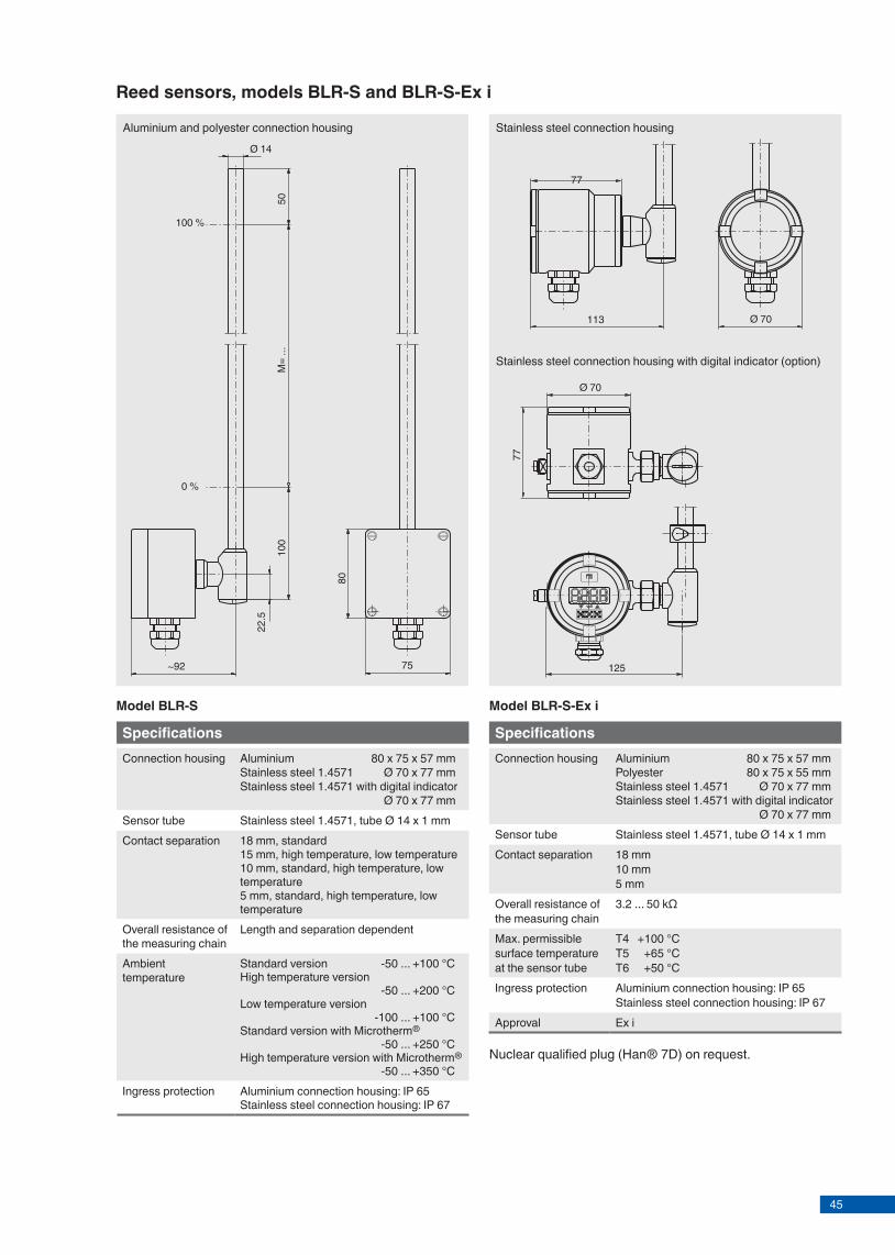
45
Model overviewSensor model
Description Approval Tempera-ture rangewithout Ex i Ex d GL DNV Ex i + GL Ex i + DNV IEEE 323
BLR-S Reed sensor, standard x x x x -50 ... +350 °CBLR-S-Ex i Reed sensor, intrinsically
safe version Ex i x x x x -50 ... +100 °C
Ex approvalsExplosion protection
Ignition protection type
Model Zone Approval number
ATEX Ex i BLR-S-Ex i Zone 1, gas KEMA 01ATEX1052 X II 2G Ex ia IIC T4 ... T6 GbEx i + GL BLR-S-Ex i Zone 1, gas KEMA 01ATEX1052 X II 2G Ex ia IIC T4 ... T6 Gb +
GL 35949-87 HHEx i + DNV BLR-S-Ex i Zone 1, gas KEMA 01ATEX1052 X II 2G Ex ia IIC T4 ... T6 Gb +
DNV A-11451
Type approvalApproval Model Approval numberGL BLR-S GL - 35 949 - 87 HHDNV BLR-S DNV A-11451IEEE 323, 344 BLR-S -GOST-R all 0959333
Options
■ 2-wire head-mounted transmitter in the connection housing.
■ Stainless steel connection housing with digital indicator. ■ External transmitter can be mounted directly in switch-
boards. ■ Nuclear qualified plug (Han® 7D) on request.
Internal circuit diagram of the reed sensors
brown blackblue/grey
Legend
Resistance
Reed contact
Page 2 of 4 KSR data sheet BLR for NPP ∙ 04/2015
Further approvals on request
SpecificationsConnection housing Aluminium 80 x 75 x 57 mm
Polyester 80 x 75 x 55 mmStainless steel 1.4571 Ø 70 x 77 mmStainless steel 1.4571 with digital indicator Ø 70 x 77 mm
Sensor tube Stainless steel 1.4571, tube Ø 14 x 1 mmContact separation 18 mm
10 mm5 mm
Overall resistance of the measuring chain
3.2 ... 50 kΩ
Max. permissible surface temperature at the sensor tube
T4 +100 °CT5 +65 °CT6 +50 °C
Ingress protection Aluminium connection housing: IP 65Stainless steel connection housing: IP 67
Approval Ex i
Reed sensors, models BLR-S and BLR-S-Ex i
~92
22.5
100
75
Ø 14
M=
...50
100 %
0 %
Aluminium and polyester connection housing
125
Ø 70
77
113
Stainless steel connection housing
80
77
Ø 70
Stainless steel connection housing with digital indicator (option)
SpecificationsConnection housing Aluminium 80 x 75 x 57 mm
Stainless steel 1.4571 Ø 70 x 77 mmStainless steel 1.4571 with digital indicator Ø 70 x 77 mm
Sensor tube Stainless steel 1.4571, tube Ø 14 x 1 mmContact separation 18 mm, standard
15 mm, high temperature, low temperature10 mm, standard, high temperature, low temperature5 mm, standard, high temperature, low temperature
Overall resistance of the measuring chain
Length and separation dependent
Ambient temperature
Standard version -50 ... +100 °CHigh temperature version -50 ... +200 °CLow temperature version -100 ... +100 °CStandard version with Microtherm®
-50 ... +250 °CHigh temperature version with Microtherm®
-50 ... +350 °CIngress protection Aluminium connection housing: IP 65
Stainless steel connection housing: IP 67
Model BLR-S Model BLR-S-Ex i
Page 3 of 4KSR data sheet BLR for NPP ∙ 04/2015
Nuclear qualified plug (Han® 7D) on request.

46
KSR KUEBLER Niveau-Messtechnik AGHeinrich-Kuebler-Platz 169439 Zwingenberg/GermanyTel. +49 6263 87-0Fax +49 6263 [email protected]
Head-mounted transmitter
Model 4 ... 20 mA HART® PROFIBUS® PA Fieldbus™ Exi SIL2 IEEE 323, 344 Display
TE x x x
TS x
T32E x x x x
T32S x x x
T53F x x
T53P x x
TLH x x x
TLEH x x x x
Model T53F Model TLEHModel TE Model T32E
© 2014 KSR KUEBLER Niveau-Messtechnik AG, all rights reserved.The specifi cations given in this document represent the state of engineering at the time of publishing.We reserve the right to make modifi cations to the specifi cations and materials.
Page 4 of 4KSR data sheet BLR for NPP ∙ 04/2015
04/2
015
EN
CE conformity
Electromagnetic compatibility (EMC)2004/108/EC
ATEX directive (option)94/9/EC, ignition protection type Ex i and Ex d, zone 1, gas
Approvals and certifi cates, see website
Approvals
■ GL, ships, shipbuilding, off shore, Germany ■ DNV, ships, shipbuilding, off shore, Norway ■ GOST, national standard for Russia, Kazakhstan and
Belarus ■ IEEE 323, standard for qualifying class 1E equipment for
nuclear power generating stations ■ IEEE 344, standard for seismic qualifi cation of equipment
for nuclear power generating stations
Magnetic switchFor bypass level indicatorsModel BGU for nuclear power plants
Magnetic switchFig. left: Reed switch, model BGUFig. right: High-temperature reed switch, model BGU-AHT
Applications
■ Magnetic switches for detecting the limits of fi lling levels in bypass level indicators
■ Chemical and petrochemical industries, oil and natural gas extraction (on- and off shore)
■ Shipbuilding, machine building ■ Power generating equipment, power plants ■ Pharmaceutical, food, water treatment, environmental
engineering industries
Special features
■ Proper functioning, even under extreme environmental infl uences, e.g. dirt, humidity, gases, dust, chips
■ Compact and operationally safe design ■ Mounting of the switches with tightening strap or via T-slot
at the magnetic display ■ Medium temperatures from -196 ... +380 °C ■ Versions with reed contact, proximity switch, micro switch
or rotation magnet
Description
The model BGU magnetic switches serve to detect the limits of fi lling levels in bypass level indicators. They generate a binary signal which can be fed to down-stream signalling or control equipment. Bistable versions enable the storage of signals.
The magnetic switches are mounted directly to the bypass level indicator with a tightening strap or to the magnetic display with sliding blocks.The magnetic switches are available with diff erent approvals and with SIL 1.
Level measurement
For selecting the optimum switch (switch model, approval, switching option, cable length, cable material) we off er application-related technical advice.
KSR data sheet BGU for NPP
Page 1 of 8KSR data sheet BGU for NPP∙ 04/2015

47
KSR KUEBLER Niveau-Messtechnik AGHeinrich-Kuebler-Platz 169439 Zwingenberg/GermanyTel. +49 6263 87-0Fax +49 6263 [email protected]
Head-mounted transmitter
Model 4 ... 20 mA HART® PROFIBUS® PA Fieldbus™ Exi SIL2 IEEE 323, 344 Display
TE x x x
TS x
T32E x x x x
T32S x x x
T53F x x
T53P x x
TLH x x x
TLEH x x x x
Model T53F Model TLEHModel TE Model T32E
© 2014 KSR KUEBLER Niveau-Messtechnik AG, all rights reserved.The specifi cations given in this document represent the state of engineering at the time of publishing.We reserve the right to make modifi cations to the specifi cations and materials.
Page 4 of 4KSR data sheet BLR for NPP ∙ 04/2015
04/2
015
EN
CE conformity
Electromagnetic compatibility (EMC)2004/108/EC
ATEX directive (option)94/9/EC, ignition protection type Ex i and Ex d, zone 1, gas
Approvals and certifi cates, see website
Approvals
■ GL, ships, shipbuilding, off shore, Germany ■ DNV, ships, shipbuilding, off shore, Norway ■ GOST, national standard for Russia, Kazakhstan and
Belarus ■ IEEE 323, standard for qualifying class 1E equipment for
nuclear power generating stations ■ IEEE 344, standard for seismic qualifi cation of equipment
for nuclear power generating stations
Magnetic switchFor bypass level indicatorsModel BGU for nuclear power plants
Magnetic switchFig. left: Reed switch, model BGUFig. right: High-temperature reed switch, model BGU-AHT
Applications
■ Magnetic switches for detecting the limits of fi lling levels in bypass level indicators
■ Chemical and petrochemical industries, oil and natural gas extraction (on- and off shore)
■ Shipbuilding, machine building ■ Power generating equipment, power plants ■ Pharmaceutical, food, water treatment, environmental
engineering industries
Special features
■ Proper functioning, even under extreme environmental infl uences, e.g. dirt, humidity, gases, dust, chips
■ Compact and operationally safe design ■ Mounting of the switches with tightening strap or via T-slot
at the magnetic display ■ Medium temperatures from -196 ... +380 °C ■ Versions with reed contact, proximity switch, micro switch
or rotation magnet
Description
The model BGU magnetic switches serve to detect the limits of fi lling levels in bypass level indicators. They generate a binary signal which can be fed to down-stream signalling or control equipment. Bistable versions enable the storage of signals.
The magnetic switches are mounted directly to the bypass level indicator with a tightening strap or to the magnetic display with sliding blocks.The magnetic switches are available with diff erent approvals and with SIL 1.
Level measurement
For selecting the optimum switch (switch model, approval, switching option, cable length, cable material) we off er application-related technical advice.
KSR data sheet BGU for NPP
Page 1 of 8KSR data sheet BGU for NPP∙ 04/2015

48
Model overviewSwitch model
Description Approval Switching power Tempera-ture rangewith-
outEx i Ex d GL Ex i
+ GLIEEE323,344
AC 230 V, 60 VA, 1 A
DC 230 V, 30 VA, 0.5 A
DC 30 V, 0.1 A Proximi-ty switch
BGU Reed, aluminium case, cable outlet
x x x x x * x x -50 ... +180 °C
BGU-A Reed, aluminium connection housing, cable gland
x x x x * x x -50 ... +180 °C
BGU-M12 Reed, aluminium case, connector M12
x x * x x -40 ... +80 °C
BGU-V Reed, stainless steel case, cable outlet
x x x x x x -50 ... +180 °C
BGU-AIH Proximity switch, high alarm, alumi-nium case, cable gland
x * x -40 ... +80 °C
BGU-AIL Proximity switch, low alarm, aluminium case, cable gland
x * x -40 ... +80 °C
Ex approvalsExplosion protection
Ignition protection type
Model Zone Approval number
ATEX Ex i BGU, BGU-A, BGU-M12, BGU-V
Zone 0, gas LCIE 01 ATEX 6047 X / ll 1 G Ex ia llC T6-T3
Ex d BGU, BGU-V Zone 1, gas LCIE 01 ATEX 6047 X / ll 2 G Ex d llC T6-T3Ex i + GL BGU, BGU-A Zone 0, gas LCIE 01 ATEX 6047 X / ll 1 G Ex ia llC T6-T3 + GL - 99 355 - 97 HH
Type approvalApproval Model Approval numberGL BGU, BGU-A GL - 99 355 - 97 HHIEEE 323, 344 BGU-V -GOST-R all 0959333
Manufacturer's declarationSwitching insert Model ZoneProximity switch BGU-AIL, BGU-AIH Zone 1
Options
■ Switching option (series resistance R22 for PLC, wiring in accordance with NAMUR per DIN EN 60497-5-6)
■ Cable length (1, 2 or 3 m, others on request) ■ Cable material (PVC cable, intrinsically safe PVC cable,
silicone cable, armoured silicone cable, LMGSG cable for GL approval)
Page 2 of 8 KSR data sheet BGU for NPP∙ 04/2015
Further approvals on request
* IEEE on request.
32 257
504210
016
3225
50
7
4210
016
Magnetic switch, reed, aluminium case, cable outlet, model BGU
SpecificationsContact Reed contactContact type 1 change-over contactSwitch behaviour BistableSwitching power
■ Model BGU
■ Model BGU-E
AC 230 V, 60 VA, 1 ADC 230 V, 30 W, 0.5 AOnly for connection to a certified intrinsically safe circuit with max. 100 mA and max. 30 V
Ambient temperature -50 … +180 °CMax. ambient temperature
■ Switch with connection cable from PVC
■ Switch with connection cable from LMGSG
■ Switch with connection cable from silicone
■ Switch model BGU-E with connection cable from PVC, blue
90 °C
150 °C
180 °C
T6 to 85 °C
Case AluminiumIngress protection IP 65Approvals Ex i
Cable gland for cables without armour
Cable gland for armoured cables
Sliding block for mounting on the left or right of the magnetic display
Model BGU-Ex d
Model BGU BGU-E
SpecificationsContact Reed contactContact type 1 change-over contactSwitch behaviour BistableSwitching power AC 230 V, 60 VA, 1 A
DC 230 V, 30 W, 0.5 AAmbient temperature -40 … +150 °CMax. ambient temperature
■ Switch with connection cable from PVC, grey
■ Switch with connection cable from silicone or armoured silicone
T6 to 85 °C
T6 to 85 °CT5 to 100 °CT4 to 135 °CT3 to 150 °C
Case AluminiumIngress protection IP 68Approvals Ex d
Sliding block for mounting on the left or right of the magnetic display
Page 3 of 8KSR data sheet BGU for NPP∙ 04/2015
Switch point Switch point
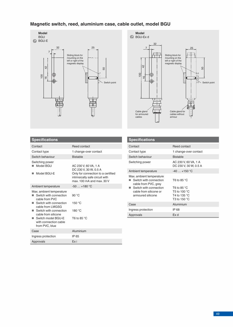
49
Model overviewSwitch model
Description Approval Switching power Tempera-ture rangewith-
outEx i Ex d GL Ex i
+ GLIEEE323,344
AC 230 V, 60 VA, 1 A
DC 230 V, 30 VA, 0.5 A
DC 30 V, 0.1 A Proximi-ty switch
BGU Reed, aluminium case, cable outlet
x x x x x * x x -50 ... +180 °C
BGU-A Reed, aluminium connection housing, cable gland
x x x x * x x -50 ... +180 °C
BGU-M12 Reed, aluminium case, connector M12
x x * x x -40 ... +80 °C
BGU-V Reed, stainless steel case, cable outlet
x x x x x x -50 ... +180 °C
BGU-AIH Proximity switch, high alarm, alumi-nium case, cable gland
x * x -40 ... +80 °C
BGU-AIL Proximity switch, low alarm, aluminium case, cable gland
x * x -40 ... +80 °C
Ex approvalsExplosion protection
Ignition protection type
Model Zone Approval number
ATEX Ex i BGU, BGU-A, BGU-M12, BGU-V
Zone 0, gas LCIE 01 ATEX 6047 X / ll 1 G Ex ia llC T6-T3
Ex d BGU, BGU-V Zone 1, gas LCIE 01 ATEX 6047 X / ll 2 G Ex d llC T6-T3Ex i + GL BGU, BGU-A Zone 0, gas LCIE 01 ATEX 6047 X / ll 1 G Ex ia llC T6-T3 + GL - 99 355 - 97 HH
Type approvalApproval Model Approval numberGL BGU, BGU-A GL - 99 355 - 97 HHIEEE 323, 344 BGU-V -GOST-R all 0959333
Manufacturer's declarationSwitching insert Model ZoneProximity switch BGU-AIL, BGU-AIH Zone 1
Options
■ Switching option (series resistance R22 for PLC, wiring in accordance with NAMUR per DIN EN 60497-5-6)
■ Cable length (1, 2 or 3 m, others on request) ■ Cable material (PVC cable, intrinsically safe PVC cable,
silicone cable, armoured silicone cable, LMGSG cable for GL approval)
Page 2 of 8 KSR data sheet BGU for NPP∙ 04/2015
Further approvals on request
* IEEE on request.
32 257
504210
016
3225
50
7
4210
016
Magnetic switch, reed, aluminium case, cable outlet, model BGU
SpecificationsContact Reed contactContact type 1 change-over contactSwitch behaviour BistableSwitching power
■ Model BGU
■ Model BGU-E
AC 230 V, 60 VA, 1 ADC 230 V, 30 W, 0.5 AOnly for connection to a certified intrinsically safe circuit with max. 100 mA and max. 30 V
Ambient temperature -50 … +180 °CMax. ambient temperature
■ Switch with connection cable from PVC
■ Switch with connection cable from LMGSG
■ Switch with connection cable from silicone
■ Switch model BGU-E with connection cable from PVC, blue
90 °C
150 °C
180 °C
T6 to 85 °C
Case AluminiumIngress protection IP 65Approvals Ex i
Cable gland for cables without armour
Cable gland for armoured cables
Sliding block for mounting on the left or right of the magnetic display
Model BGU-Ex d
Model BGU BGU-E
SpecificationsContact Reed contactContact type 1 change-over contactSwitch behaviour BistableSwitching power AC 230 V, 60 VA, 1 A
DC 230 V, 30 W, 0.5 AAmbient temperature -40 … +150 °CMax. ambient temperature
■ Switch with connection cable from PVC, grey
■ Switch with connection cable from silicone or armoured silicone
T6 to 85 °C
T6 to 85 °CT5 to 100 °CT4 to 135 °CT3 to 150 °C
Case AluminiumIngress protection IP 68Approvals Ex d
Sliding block for mounting on the left or right of the magnetic display
Page 3 of 8KSR data sheet BGU for NPP∙ 04/2015
Switch point Switch point

50
Magnetic switch, reed, aluminium connection housing, cable gland, model BGU-A
Model BGU-A BGU-A-E
BGU-A-GL
592532
100
50
32 255.5
114
100
4216
50
Sliding block
Sliding block
M16x1.5
Sliding block for mounting on the left or right of the magnetic display
Model BGU-M12
BGU-E-M12
Magnetic switch, reed, aluminium case, connector M12, model BGU-M12
Specifications
Contact Reed contactContact type 1 change-over contactSwitch behaviour BistableSwitching power
■ Models BGU-A, BGU-A-GL
■ Model BGU-A-E
AC 230 V, 60 VA, 1 ADC 230 V, 30 W, 0.5 AOnly for connection to a certi-fied intrinsically safe circuit with max. 100 mA and max. 30 V
Ambient temperature -50 … +180 °CMax. ambient temperature
■ Model BGU-A ■ Model BGU-A-GL ■ Model BGU-A-E
180 °C150 °CT6 to 85 °CT5 to 100 °CT4 to 135 °CT3 to 150 °C
Case Aluminium, cable connection M16 x 1.5 *
Ingress protection IP 65Approvals Ex i
SpecificationsContact Reed contactContact type 1 change-over contactSwitch behaviour BistableSwitching power
■ Model BGU-M12
■ Model BGU-E-M12
AC 230 V, 60 VA, 1 ADC 230 V, 30 W, 0.5 AOnly for connection to a certified intrinsically safe circuit with max. 100 mA and max. 30 V
Ambient temperature -40 … +80 °CMax. ambient temperature
■ Model BGU-M12 ■ Model BGU-E-M12
80 °CT6 to 80 °C
Case AluminiumIngress protection IP 67Approvals Ex i
Model BGU-M12, with mating connector and 2 m PVC cable
Page 4 of 8 KSR data sheet BGU for NPP∙ 04/2015
Switch point
Switch point
* Nuclear qualified plug (Han® 7D) on request.
100
21,3
50 50
21,3
100
Switch point
Magnetic switch, reed, stainless steel case, cable outlet, model BGU-V
SpecificationsContact Reed contactContact type 1 change-over contactSwitch behaviour BistableSwitching power
■ Model BGU-V
■ Model BGU-V-E
AC 230 V, 60 VA, 1 ADC 230 V, 30 W, 0.5 AOnly for connection to a certified intrinsically safe circuit with max. 100 mA and max. 30 V
Ambient temperature -50 … +180 °CMax. ambient temperature
■ Switch with connection cable from PVC
■ Switch with connection cable from silicone
■ Switch model BGU-V-E with connection cable from PVC, blue
90 °C
180 °C
T6 to 85 °C
Case Stainless steel 1.4571 (316Ti)Ingress protection IP 65Approvals Ex i
Cable gland for cables without armour
Cable gland for armoured cables
Model BGU-V-Ex d
Model BGU-V BGU-V-E
SpecificationsContact Reed contactContact type 1 change-over contactSwitch behaviour BistableSwitching power AC 230 V, 60 VA, 1 A
DC 230 V, 30 W, 0.5 AAmbient temperature -50 … +150 °CMax. ambient temperature
■ Switch with connection cable from PVC, grey
■ Switch with connection cable from silicone or armoured silicone
T6 to 85 °C
T6 to 85 °CT5 to 100 °CT4 to 135 °CT3 to 150 °C
Case Stainless steel 1.4571 (316Ti)Ingress protection IP 68Approvals Ex d
Page 5 of 8KSR data sheet BGU for NPP∙ 04/2015
Switch point

51
Magnetic switch, reed, aluminium connection housing, cable gland, model BGU-A
Model BGU-A BGU-A-E
BGU-A-GL
592532
100
50
32 255.5
114
100
4216
50
Sliding block
Sliding block
M16x1.5
Sliding block for mounting on the left or right of the magnetic display
Model BGU-M12
BGU-E-M12
Magnetic switch, reed, aluminium case, connector M12, model BGU-M12
Specifications
Contact Reed contactContact type 1 change-over contactSwitch behaviour BistableSwitching power
■ Models BGU-A, BGU-A-GL
■ Model BGU-A-E
AC 230 V, 60 VA, 1 ADC 230 V, 30 W, 0.5 AOnly for connection to a certi-fied intrinsically safe circuit with max. 100 mA and max. 30 V
Ambient temperature -50 … +180 °CMax. ambient temperature
■ Model BGU-A ■ Model BGU-A-GL ■ Model BGU-A-E
180 °C150 °CT6 to 85 °CT5 to 100 °CT4 to 135 °CT3 to 150 °C
Case Aluminium, cable connection M16 x 1.5 *
Ingress protection IP 65Approvals Ex i
SpecificationsContact Reed contactContact type 1 change-over contactSwitch behaviour BistableSwitching power
■ Model BGU-M12
■ Model BGU-E-M12
AC 230 V, 60 VA, 1 ADC 230 V, 30 W, 0.5 AOnly for connection to a certified intrinsically safe circuit with max. 100 mA and max. 30 V
Ambient temperature -40 … +80 °CMax. ambient temperature
■ Model BGU-M12 ■ Model BGU-E-M12
80 °CT6 to 80 °C
Case AluminiumIngress protection IP 67Approvals Ex i
Model BGU-M12, with mating connector and 2 m PVC cable
Page 4 of 8 KSR data sheet BGU for NPP∙ 04/2015
Switch point
Switch point
* Nuclear qualified plug (Han® 7D) on request.
100
21,3
50 50
21,3
100
Switch point
Magnetic switch, reed, stainless steel case, cable outlet, model BGU-V
SpecificationsContact Reed contactContact type 1 change-over contactSwitch behaviour BistableSwitching power
■ Model BGU-V
■ Model BGU-V-E
AC 230 V, 60 VA, 1 ADC 230 V, 30 W, 0.5 AOnly for connection to a certified intrinsically safe circuit with max. 100 mA and max. 30 V
Ambient temperature -50 … +180 °CMax. ambient temperature
■ Switch with connection cable from PVC
■ Switch with connection cable from silicone
■ Switch model BGU-V-E with connection cable from PVC, blue
90 °C
180 °C
T6 to 85 °C
Case Stainless steel 1.4571 (316Ti)Ingress protection IP 65Approvals Ex i
Cable gland for cables without armour
Cable gland for armoured cables
Model BGU-V-Ex d
Model BGU-V BGU-V-E
SpecificationsContact Reed contactContact type 1 change-over contactSwitch behaviour BistableSwitching power AC 230 V, 60 VA, 1 A
DC 230 V, 30 W, 0.5 AAmbient temperature -50 … +150 °CMax. ambient temperature
■ Switch with connection cable from PVC, grey
■ Switch with connection cable from silicone or armoured silicone
T6 to 85 °C
T6 to 85 °CT5 to 100 °CT4 to 135 °CT3 to 150 °C
Case Stainless steel 1.4571 (316Ti)Ingress protection IP 68Approvals Ex d
Page 5 of 8KSR data sheet BGU for NPP∙ 04/2015
Switch point

52
122
7511
1
M20 x 1.5
122
7511
1
SpecificationsContact Inductive proximity sensor
SJ 3.5-SNContact type Code AIH: High alarm
Code AIL: Low alarmSwitch behaviour BistableNominal voltage DC 8 V (Ri ~1 kΩ)Permissible residual ripple < 5 %Operating voltage UB 5 ... 25 VCurrent supply active area free: > 3 mA
active area covered: > 1 mAPermissible resistance of control cable
< 100 Ω
Self-inductance 160 μHSelf-capacitance 20 nFAmbient temperature -40 … +80 °CCase Aluminium, 80 x 75 x 57 mm
Cable connection M20 x 1.5 *Ingress protection IP 65
Mounting to magnetic display with T-slot
Mounting with tightening strap
AccessoriesTightening strap Standard: OD 50-70 mm
Option: OD 30-45, 40-60, 60-80, 80-100 mm
Magnetic switch, proximity switch, aluminium case, cable gland, model BGU-AIH, high alarm and model BGU-AIL, low alarm
Model Normally open with Mounting BGU-AIH rising level T-slot BGU-AIL falling level T-slot BGU-AIH rising level Tightening strap BGU-AIL falling level Tightening strap
Magnetic switch, rotational switch, aluminium case, cable gland, model BGU-AR
Model Mounting BGU-AR T-slot BGU-AR Tightening strap BGU-AR m Tightening strap (with Microtherm®)
SpecificationsContact Rotary magnet with contact rocker switchContact type 1 change-over contactSwitch behaviour BistableSwitching power AC 250 V, 100 VA, 2 A
DC 200 V, 40 W, 2 AAmbient temperature 1) -60 ... +250 °C
-60 ... +380 °C with Microtherm®
Case Aluminium, 80 x 75 x 57 mmCable connection M20 x 1.5 *
Ingress protection IP 65
AccessoriesTightening strap Standard: OD 50-70 mm
Option: OD 30-45, 40-60, 60-80, 80-100 mm
122
7511
1
M20 x 1.5
122
7511
1
Mounting to magnetic display with T-slot
Mounting with tightening strapMounting with tightening strap
Page 6 of 8KSR data sheet BGU for NPP∙ 04/2015
1 ) With additional insulation the temperature ranges can change
* Nuclear qualified plug (Han® 7D) on request.
122
7511
1
M20 x 1.5
Specifi cationsContact Reed contactContact type 1 change-over contactSwitch behaviour BistableSwitching power AC 230 V, 60 VA, 1 A
DC 230 V, 30 W, 0.5 AAmbient temperature 1) -196 ... +380 °CCase Aluminium, 80 x 75 x 57 mm
Cable connection M20 x 1.5Ingress protection IP 65
Mounting to magnetic display with T-slot
Mounting with tightening strap AccessoriesMounting with tightening strap, including Mikroterm®
Magnetic switch, reed, high temperature, aluminium case, cable gland, model BGU-AHT
Model Mounting BGU-AHT T-slot BGU-AHT Tightening strap
Page 7 of 8 KSR data sheet BGU for NPP∙ 04/2015
1 ) With additional insulation the temperature ranges can change
Electrical connections
1 switch pointWiring for operation with a PLC
1 switch pointNAMUR circuit per DIN EN 60947-5-6
1 switch point
Reed contact, micro switch, rotation magnet
Proximity switch(for models BGU-AIH and BGU-AIL)
BN (1)
SJ 3.5 SN
GY (2)
(1)
(2)
(3)
10k1k
10k
(1)
(2)
(3)
(1)
(2)
(3)
R22
BU/GY
BN
BK
BU/GY
BN
BK
BU/GY
BN
BK
2 WH4 BK
1 BN
5-pin(only with Ex)
1
42
2 WH4 BK
1 BN1
42
5 PE5
Connector M12, pin assignment(for model BGU-M12)
Instrument Mating connector with cable2 WH
1 BN
4 BK
Further plugs on request.
Nuclear qualifi ed plug (Han® 7D) on request.

53
122
7511
1
M20 x 1.5
122
7511
1
SpecificationsContact Inductive proximity sensor
SJ 3.5-SNContact type Code AIH: High alarm
Code AIL: Low alarmSwitch behaviour BistableNominal voltage DC 8 V (Ri ~1 kΩ)Permissible residual ripple < 5 %Operating voltage UB 5 ... 25 VCurrent supply active area free: > 3 mA
active area covered: > 1 mAPermissible resistance of control cable
< 100 Ω
Self-inductance 160 μHSelf-capacitance 20 nFAmbient temperature -40 … +80 °CCase Aluminium, 80 x 75 x 57 mm
Cable connection M20 x 1.5 *Ingress protection IP 65
Mounting to magnetic display with T-slot
Mounting with tightening strap
AccessoriesTightening strap Standard: OD 50-70 mm
Option: OD 30-45, 40-60, 60-80, 80-100 mm
Magnetic switch, proximity switch, aluminium case, cable gland, model BGU-AIH, high alarm and model BGU-AIL, low alarm
Model Normally open with Mounting BGU-AIH rising level T-slot BGU-AIL falling level T-slot BGU-AIH rising level Tightening strap BGU-AIL falling level Tightening strap
Magnetic switch, rotational switch, aluminium case, cable gland, model BGU-AR
Model Mounting BGU-AR T-slot BGU-AR Tightening strap BGU-AR m Tightening strap (with Microtherm®)
SpecificationsContact Rotary magnet with contact rocker switchContact type 1 change-over contactSwitch behaviour BistableSwitching power AC 250 V, 100 VA, 2 A
DC 200 V, 40 W, 2 AAmbient temperature 1) -60 ... +250 °C
-60 ... +380 °C with Microtherm®
Case Aluminium, 80 x 75 x 57 mmCable connection M20 x 1.5 *
Ingress protection IP 65
AccessoriesTightening strap Standard: OD 50-70 mm
Option: OD 30-45, 40-60, 60-80, 80-100 mm
122
7511
1
M20 x 1.5
122
7511
1
Mounting to magnetic display with T-slot
Mounting with tightening strapMounting with tightening strap
Page 6 of 8KSR data sheet BGU for NPP∙ 04/2015
1 ) With additional insulation the temperature ranges can change
* Nuclear qualified plug (Han® 7D) on request.
122
7511
1
M20 x 1.5
Specifi cationsContact Reed contactContact type 1 change-over contactSwitch behaviour BistableSwitching power AC 230 V, 60 VA, 1 A
DC 230 V, 30 W, 0.5 AAmbient temperature 1) -196 ... +380 °CCase Aluminium, 80 x 75 x 57 mm
Cable connection M20 x 1.5Ingress protection IP 65
Mounting to magnetic display with T-slot
Mounting with tightening strap AccessoriesMounting with tightening strap, including Mikroterm®
Magnetic switch, reed, high temperature, aluminium case, cable gland, model BGU-AHT
Model Mounting BGU-AHT T-slot BGU-AHT Tightening strap
Page 7 of 8 KSR data sheet BGU for NPP∙ 04/2015
1 ) With additional insulation the temperature ranges can change
Electrical connections
1 switch pointWiring for operation with a PLC
1 switch pointNAMUR circuit per DIN EN 60947-5-6
1 switch point
Reed contact, micro switch, rotation magnet
Proximity switch(for models BGU-AIH and BGU-AIL)
BN (1)
SJ 3.5 SN
GY (2)
(1)
(2)
(3)
10k1k
10k
(1)
(2)
(3)
(1)
(2)
(3)
R22
BU/GY
BN
BK
BU/GY
BN
BK
BU/GY
BN
BK
2 WH4 BK
1 BN
5-pin(only with Ex)
1
42
2 WH4 BK
1 BN1
42
5 PE5
Connector M12, pin assignment(for model BGU-M12)
Instrument Mating connector with cable2 WH
1 BN
4 BK
Further plugs on request.
Nuclear qualifi ed plug (Han® 7D) on request.

54
KSR KUEBLER Niveau-Messtechnik AGHeinrich-Kuebler-Platz 169439 Zwingenberg/GermanyTel. +49 6263 87-0Fax +49 6263 [email protected]
© 2014 KSR KUEBLER Niveau-Messtechnik AG, all rights reserved.The specifi cations given in this document represent the state of engineering at the time of publishing.We reserve the right to make modifi cations to the specifi cations and materials.
KSR data sheet BGU for NPP∙ 04/2015
04/2
015
EN
Page 8 of 8
Colour Short symbol
Black BKBrown BNRed RDOrange OGYellow YEGreen GNBlue BUViolet VTGrey GYWhite WHPink PKTurquoise TQGreen-Yellow GNYE
Connection cable Cross-section
PVC 4 x 0.5 mm2
Silicone 4 x 0.75 mm2
Armoured silicone 4 x 0.75 mm2
LMGSG 3 x 1.5 mm2
Colour coding per IEC 60757
Connection cable(for models BGU and BGU-V)
CE conformity
Electromagnetic compatibility (EMC)2004/108/EC
ATEX directive (option)94/9/EC, ignition protection type Ex i, zone 0, gas94/9/EC, ignition protection type Ex d, zone 1, gas, dust
Approvals
■ GL, ships, shipbuilding, off shore, Germany ■ GOST, national standard for Russia, Kazakhstan and
Belarus ■ IEEE 323, standard for qualifying class 1E equipment for
nuclear power generating stations ■ IEEE 344, standard for seismic qualifi cation of equipment
for nuclear power generating stations
Magnetic fl oat switchFor vertical installationModel FLS for nuclear power plants
Fig.: Stainless steel version, mounting thread
Applications
■ Level measurement for almost all liquid media ■ Pump and level control and monitoring for distinct fi lling
levels ■ Chemical, petrochemical, natural gas, off shore, shipbuil-
ding, machine building, power generating equipment, power plants
■ Process water and drinking water treatment, food and beverage industry
Special features
■ Large range of application due to the simple, proven functional principle
■ For harsh operating conditions, long service life ■ Operating limits:
- Operating temperature: T = -196 ... +350 °C- Operating pressure: P = Vacuum to 40 bar- Limit density: ρ ≥ 300 kg/m3
■ Wide variety of diff erent electrical connections, process connections and materials
■ Explosion-protected versions
DescriptionA fl oat with a permanent magnet moves reliably along with the liquid level on a guide tube. Within the guide tube is fi tted a reed contact (inert gas contact), which is energised, through the non-magnetic walls of the fl oat and guide tube, by the approach of the fl oat magnet. By using a magnet and reed contact the switching operation is non-contact, free from wear and needs no power supply. The contacts are potential-free. Magnetic fl oat switches are also available with multiple switch points.
The switch functions always refer to a rising liquid level: normally open, normally closed or change-over contact.
Through the use of a fl oat for a max. of 2 switch points a bistable switch operation can be achieved, meaning that the switching status also remains available, when the fi lling level continues to rise above or drop below the switch point.
The fl oat switch is simple to mount and maintenance-free, so the costs of mounting, commissioning and operation are low.
Level measurement
for further approvals see page 3
KSR data sheet FLS for NPP
Page 1 of 8KSR data sheet FLS for NPP ∙ 04/2015

55
KSR KUEBLER Niveau-Messtechnik AGHeinrich-Kuebler-Platz 169439 Zwingenberg/GermanyTel. +49 6263 87-0Fax +49 6263 [email protected]
© 2014 KSR KUEBLER Niveau-Messtechnik AG, all rights reserved.The specifi cations given in this document represent the state of engineering at the time of publishing.We reserve the right to make modifi cations to the specifi cations and materials.
KSR data sheet BGU for NPP∙ 04/2015
04/2
015
EN
Page 8 of 8
Colour Short symbol
Black BKBrown BNRed RDOrange OGYellow YEGreen GNBlue BUViolet VTGrey GYWhite WHPink PKTurquoise TQGreen-Yellow GNYE
Connection cable Cross-section
PVC 4 x 0.5 mm2
Silicone 4 x 0.75 mm2
Armoured silicone 4 x 0.75 mm2
LMGSG 3 x 1.5 mm2
Colour coding per IEC 60757
Connection cable(for models BGU and BGU-V)
CE conformity
Electromagnetic compatibility (EMC)2004/108/EC
ATEX directive (option)94/9/EC, ignition protection type Ex i, zone 0, gas94/9/EC, ignition protection type Ex d, zone 1, gas, dust
Approvals
■ GL, ships, shipbuilding, off shore, Germany ■ GOST, national standard for Russia, Kazakhstan and
Belarus ■ IEEE 323, standard for qualifying class 1E equipment for
nuclear power generating stations ■ IEEE 344, standard for seismic qualifi cation of equipment
for nuclear power generating stations
Magnetic fl oat switchFor vertical installationModel FLS for nuclear power plants
Fig.: Stainless steel version, mounting thread
Applications
■ Level measurement for almost all liquid media ■ Pump and level control and monitoring for distinct fi lling
levels ■ Chemical, petrochemical, natural gas, off shore, shipbuil-
ding, machine building, power generating equipment, power plants
■ Process water and drinking water treatment, food and beverage industry
Special features
■ Large range of application due to the simple, proven functional principle
■ For harsh operating conditions, long service life ■ Operating limits:
- Operating temperature: T = -196 ... +350 °C- Operating pressure: P = Vacuum to 40 bar- Limit density: ρ ≥ 300 kg/m3
■ Wide variety of diff erent electrical connections, process connections and materials
■ Explosion-protected versions
DescriptionA fl oat with a permanent magnet moves reliably along with the liquid level on a guide tube. Within the guide tube is fi tted a reed contact (inert gas contact), which is energised, through the non-magnetic walls of the fl oat and guide tube, by the approach of the fl oat magnet. By using a magnet and reed contact the switching operation is non-contact, free from wear and needs no power supply. The contacts are potential-free. Magnetic fl oat switches are also available with multiple switch points.
The switch functions always refer to a rising liquid level: normally open, normally closed or change-over contact.
Through the use of a fl oat for a max. of 2 switch points a bistable switch operation can be achieved, meaning that the switching status also remains available, when the fi lling level continues to rise above or drop below the switch point.
The fl oat switch is simple to mount and maintenance-free, so the costs of mounting, commissioning and operation are low.
Level measurement
for further approvals see page 3
KSR data sheet FLS for NPP
Page 1 of 8KSR data sheet FLS for NPP ∙ 04/2015

56
Model overviewFloat switch model
Description Approvalwithout Ex i Ex d GL Ex i + GL ABS DNV
FLS-S Magnetic float switch, standard version
x x x x x x x
Float switch model
Materials Temperature rangeStainless steel
1.4571 (316Ti)Stainless steel 1.4404 (316L)
Stainless steel 1.4435 (316L)
FLS-S x x x -50 ... +350 °C
KSR data sheet FLS for NPP ∙ 04/2015Page 2 of 8
Further special features
■ Process connection, guide tube and float from stainless steel 1.4571, plastic or Buna
■ Universal signal processing: connection direct to a PLC is possible, NAMUR connection, signal amplification / contact protection relays
■ Works independently of foaming, conductivity, dielectricity, pressure, vacuum, temperature, steam, condensation, bubble formation, boiling effects and vibrations.
■ Multiple functionality in a single instrument - up to 8 potential-free contacts
■ Exact repeatability of the switch points ■ Magnetic float switches qualify as passive electrical
equipment in accordance with DIN IEC 60079-11 and can be installed in 'Zone 1' hazardous areas without certification, so long as the equipment is operated in a certified intrinsically safe circuit with a minimum explosion protection of EEx ib
Options
■ Customer-specific solutions ■ Special versions for interface layer detection
∆-ρ ≥ 100 kg/m3
■ Process connection, guide tube material and float from stainless steel 1.4435, 1.4539, titanium, Hastelloy (others on request)
Ex approvalsExplosion protection
Ignition pro-tection type
Model Zone Approval number
ATEX Ex i FLS-S Zone 0, gas KEMA 01 ATEX1053 X II 1/2G Ex ia IIC T3 ... T6Ex i FLS-M Zone 0, gas KEMA 01 ATEX1053 X II 1/2G Ex ia IIC T3 ... T6Ex d FLS-S Zone 1, gas/dust TÜV 13 ATEX 7399 X II 2G Ex d IIC T6 Gb /
II 2 D Ex tb IIIC T80 °C DbEx i + GL FLS-S Zone 0, gas KEMA 01 ATEX1053 X II 1/2G Ex ia IIC T3 ... T6 +
GL - 96 716 - 95 HH
Type approvalExplosion protection
Model Approval number
GL FLS-S GL - 96 716 - 95 HHABS FLS-S ABS-02-HG286246-2-PDADNV FLS-S DNV - A-11453GOST FLS-S 959333
Page 3 of 8KSR data sheet FLS for NPP ∙ 04/2015
Application examples
Ex zone non-Ex zone
intrinsically safe
Intrinsically safe relay e.g. KR 24 Ex
Ex zone non-Ex zone
intrinsically safe
Intrinsically safe relay e.g. KR 24 Ex
Contact protection relay e.g. KR 230
Contact protection relay e.g. KR 24
Full detector (EEx i)
Level control (min.-max. control)
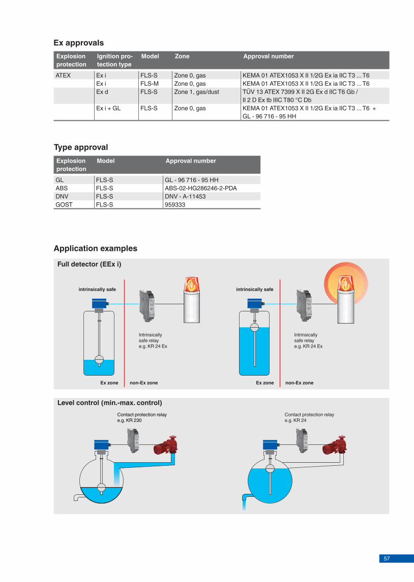
57
Model overviewFloat switch model
Description Approvalwithout Ex i Ex d GL Ex i + GL ABS DNV
FLS-S Magnetic float switch, standard version
x x x x x x x
Float switch model
Materials Temperature rangeStainless steel
1.4571 (316Ti)Stainless steel 1.4404 (316L)
Stainless steel 1.4435 (316L)
FLS-S x x x -50 ... +350 °C
KSR data sheet FLS for NPP ∙ 04/2015Page 2 of 8
Further special features
■ Process connection, guide tube and float from stainless steel 1.4571, plastic or Buna
■ Universal signal processing: connection direct to a PLC is possible, NAMUR connection, signal amplification / contact protection relays
■ Works independently of foaming, conductivity, dielectricity, pressure, vacuum, temperature, steam, condensation, bubble formation, boiling effects and vibrations.
■ Multiple functionality in a single instrument - up to 8 potential-free contacts
■ Exact repeatability of the switch points ■ Magnetic float switches qualify as passive electrical
equipment in accordance with DIN IEC 60079-11 and can be installed in 'Zone 1' hazardous areas without certification, so long as the equipment is operated in a certified intrinsically safe circuit with a minimum explosion protection of EEx ib
Options
■ Customer-specific solutions ■ Special versions for interface layer detection
∆-ρ ≥ 100 kg/m3
■ Process connection, guide tube material and float from stainless steel 1.4435, 1.4539, titanium, Hastelloy (others on request)
Ex approvalsExplosion protection
Ignition pro-tection type
Model Zone Approval number
ATEX Ex i FLS-S Zone 0, gas KEMA 01 ATEX1053 X II 1/2G Ex ia IIC T3 ... T6Ex i FLS-M Zone 0, gas KEMA 01 ATEX1053 X II 1/2G Ex ia IIC T3 ... T6Ex d FLS-S Zone 1, gas/dust TÜV 13 ATEX 7399 X II 2G Ex d IIC T6 Gb /
II 2 D Ex tb IIIC T80 °C DbEx i + GL FLS-S Zone 0, gas KEMA 01 ATEX1053 X II 1/2G Ex ia IIC T3 ... T6 +
GL - 96 716 - 95 HH
Type approvalExplosion protection
Model Approval number
GL FLS-S GL - 96 716 - 95 HHABS FLS-S ABS-02-HG286246-2-PDADNV FLS-S DNV - A-11453GOST FLS-S 959333
Page 3 of 8KSR data sheet FLS for NPP ∙ 04/2015
Application examples
Ex zone non-Ex zone
intrinsically safe
Intrinsically safe relay e.g. KR 24 Ex
Ex zone non-Ex zone
intrinsically safe
Intrinsically safe relay e.g. KR 24 Ex
Contact protection relay e.g. KR 230
Contact protection relay e.g. KR 24
Full detector (EEx i)
Level control (min.-max. control)

58KSR data sheet FLS for NPP ∙ 04/2015Page 4 of 8
Magnetic float switch, standard version, model FLS-SProcess connection, guide tube material and float from stainless steel 1.4571 (316Ti)
Mounting thread(without connection housing)
Mounting thread Flange
Electrical connection Connection cable PVC Silicone PUR
Connection housing Aluminium 64 x 58 x 34 mm, with 1 contact Aluminium 80 x 75 x 57 mm, 2 or more contacts Option: Polypropylene, polyester, stainless steel
Process connection Mounting threadupwardsG 3/8" (others on G 1/2" (others on request) on request)
Mounting threaddownwards G 1 1/2" or G 2"
Mounting flange DIN DN 50 ... DN 200, PN 6 ... PN 100 ANSI 2" ... 8", class 150 ... 600
Guide tube diameter 12 or 14 mm 18 mm 12 or 14 mm 18 mm 12 or 14 mm 18 mm
Guide tube length L max. 3,000 mm 6,000 mm 3,000 mm 6,000 mm 3,000 mm 6,000 mm
Float Material stainless steel 1.4571 Float diameter from 44 ... 120 mmFloat selection depending on guide tube diameter and process conditions (see floats (K) and (Z))
Temperature range standard
PVC cable -10 ... +80 °CSilicone cable -30 ... +130 °C
-30 ... +150 °COption: High-temperature version: +150 ... +300 °COption: Low-temperature version: -196 ... -30 °C
Switching function Alternatively normally open (NO), normally closed (NC) or change-over (SPDT) contact - on rising level
max. number of contacts
PVC cable 6 x NO or NC, or 4 x SPDT Silicone cable 5 x NO or NC, or 3 x SPDT
6 x NO or NC, or 4 x SPDT
Switch position Dimensions L1, L2, L3 ... (from sealing face, starting from top)
Distance between switch points
Minimum 20 mm (depending on the selection of the float and the contacts, see floats (K) and (Z))
Switching power Normally open AC 230 V; 100 VA; 1 A DC 230 V; 50 W; 0.5 A Normally closed AC 230 V; 100 VA; 1 A DC 230 V; 50 W; 0.5 A Please observe contact protection measures! Change-over AC 230 V; 40 VA; 1 A DC 230 V; 20 W; 0.5 AChange-over - DC 30 V; 0.1 A
Attention: Versions without protective conductor connection - operation only at safety extra-low voltage e.g. KSR contact protection relay or external grounding
Mounting position Vertical ±30°
Ingress protection IP 65 per EN 60529 / lEC 60529
Materials Stainless steel 1.4404, 1.4435, 1.4539, titanium, Hastelloy and others on request
Connection cable
L 1
= ...
L =
...
L 1
= ...
L =
...
L 1
= ...
L =
...
Connection housing
Connection housing
L 1
= ...
L =
...
L 1
= ...
L =
...
Page 5 of 8KSR data sheet FLS for NPP ∙ 04/2015
Magnetic float switch, explosion-protected version Ex i, intrinsically safe, model FLS-SProcess connection, guide tube material and float from stainless steel 1.4571 (316Ti)
Mounting thread Flange
Electrical connection Connection housing Aluminium 80 x 75 x 57 mm Option: Polyester, stainless steel
Process connection Mounting threaddownwards G 1 1/2" or G 2" (others on request)
Mounting flange DIN DN 50 ... DN 150, PN 6 ... PN 64 ANSI 2" ... 6", class 150 ... 600
Guide tube diameter 12 or 14 mm 18 mm 30 mm 12 or 14 mm 18 mm 30 mm
Guide tube length L max. 3,000 mm 6,000 mm 15, 000 mm 3,000 mm 6,000 mm 15, 000 mm
Float Material stainless steel 1.4571Float diameter from 44 ... 120 mmFloat selection depending on guide tube diameter and process conditions (see floats (K) and (Z))
Temperature class Process temperature
Ambient tempera-ture at connection housing
T3 T4 T5 T6Max. 180 °C 130 °C 95 °C 80 °C
Max. 60 °C 60 °C 60 °C 60 °C
Switching function Alternatively normally open (NO), normally closed (NC) or change-over (SPDT) contact - on rising level
max. number of contacts
6 x NO or NC, or 4 x SPDT
Switch position Dimensions L1, L2, L3 ... (from sealing face, starting from top)
Distance between switch points
Minimum 20 mm (depending on the selection of the float and the contacts, see floats (K) and (Z))
Switching power Only for connection to a certified intrinsically safe circuit with Umax 30 V, Imax 100 mA
Mounting position Vertical ±30°
Ingress protection IP 65 per EN 60529 / lEC 60529
Options Housing heightening X (state dimension X) Temperature resistance Pt100 or Pt1000 Bimetal thermal contact 40 ... 120 °C (in 5 degree steps)
Materials Stainless steel 1.4435, titanium, Hastelloy on request
Connection housing
Connection housing
X X
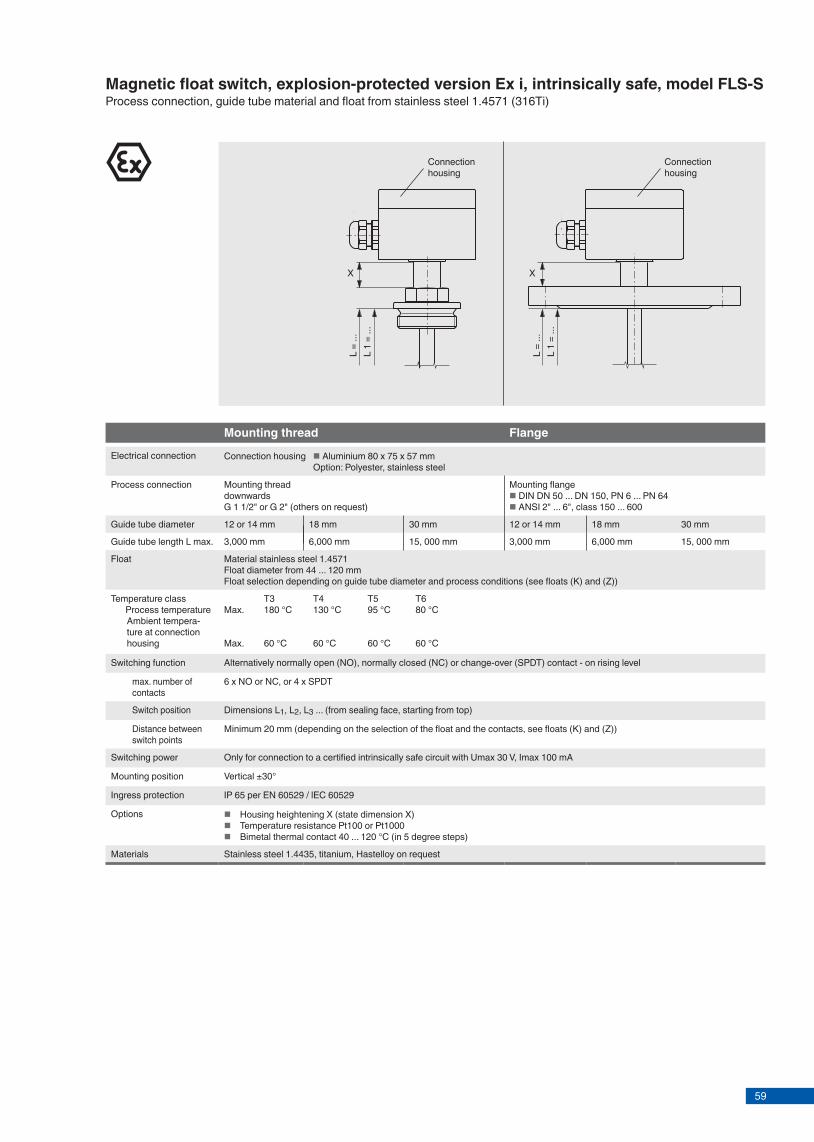
59KSR data sheet FLS for NPP ∙ 04/2015Page 4 of 8
Magnetic float switch, standard version, model FLS-SProcess connection, guide tube material and float from stainless steel 1.4571 (316Ti)
Mounting thread(without connection housing)
Mounting thread Flange
Electrical connection Connection cable PVC Silicone PUR
Connection housing Aluminium 64 x 58 x 34 mm, with 1 contact Aluminium 80 x 75 x 57 mm, 2 or more contacts Option: Polypropylene, polyester, stainless steel
Process connection Mounting threadupwardsG 3/8" (others on G 1/2" (others on request) on request)
Mounting threaddownwards G 1 1/2" or G 2"
Mounting flange DIN DN 50 ... DN 200, PN 6 ... PN 100 ANSI 2" ... 8", class 150 ... 600
Guide tube diameter 12 or 14 mm 18 mm 12 or 14 mm 18 mm 12 or 14 mm 18 mm
Guide tube length L max. 3,000 mm 6,000 mm 3,000 mm 6,000 mm 3,000 mm 6,000 mm
Float Material stainless steel 1.4571 Float diameter from 44 ... 120 mmFloat selection depending on guide tube diameter and process conditions (see floats (K) and (Z))
Temperature range standard
PVC cable -10 ... +80 °CSilicone cable -30 ... +130 °C
-30 ... +150 °COption: High-temperature version: +150 ... +300 °COption: Low-temperature version: -196 ... -30 °C
Switching function Alternatively normally open (NO), normally closed (NC) or change-over (SPDT) contact - on rising level
max. number of contacts
PVC cable 6 x NO or NC, or 4 x SPDT Silicone cable 5 x NO or NC, or 3 x SPDT
6 x NO or NC, or 4 x SPDT
Switch position Dimensions L1, L2, L3 ... (from sealing face, starting from top)
Distance between switch points
Minimum 20 mm (depending on the selection of the float and the contacts, see floats (K) and (Z))
Switching power Normally open AC 230 V; 100 VA; 1 A DC 230 V; 50 W; 0.5 A Normally closed AC 230 V; 100 VA; 1 A DC 230 V; 50 W; 0.5 A Please observe contact protection measures! Change-over AC 230 V; 40 VA; 1 A DC 230 V; 20 W; 0.5 AChange-over - DC 30 V; 0.1 A
Attention: Versions without protective conductor connection - operation only at safety extra-low voltage e.g. KSR contact protection relay or external grounding
Mounting position Vertical ±30°
Ingress protection IP 65 per EN 60529 / lEC 60529
Materials Stainless steel 1.4404, 1.4435, 1.4539, titanium, Hastelloy and others on request
Connection cable
L 1
= ...
L =
...
L 1
= ...
L =
...
L 1
= ...
L =
...
Connection housing
Connection housing
L 1
= ...
L =
...
L 1
= ...
L =
...
Page 5 of 8KSR data sheet FLS for NPP ∙ 04/2015
Magnetic float switch, explosion-protected version Ex i, intrinsically safe, model FLS-SProcess connection, guide tube material and float from stainless steel 1.4571 (316Ti)
Mounting thread Flange
Electrical connection Connection housing Aluminium 80 x 75 x 57 mm Option: Polyester, stainless steel
Process connection Mounting threaddownwards G 1 1/2" or G 2" (others on request)
Mounting flange DIN DN 50 ... DN 150, PN 6 ... PN 64 ANSI 2" ... 6", class 150 ... 600
Guide tube diameter 12 or 14 mm 18 mm 30 mm 12 or 14 mm 18 mm 30 mm
Guide tube length L max. 3,000 mm 6,000 mm 15, 000 mm 3,000 mm 6,000 mm 15, 000 mm
Float Material stainless steel 1.4571Float diameter from 44 ... 120 mmFloat selection depending on guide tube diameter and process conditions (see floats (K) and (Z))
Temperature class Process temperature
Ambient tempera-ture at connection housing
T3 T4 T5 T6Max. 180 °C 130 °C 95 °C 80 °C
Max. 60 °C 60 °C 60 °C 60 °C
Switching function Alternatively normally open (NO), normally closed (NC) or change-over (SPDT) contact - on rising level
max. number of contacts
6 x NO or NC, or 4 x SPDT
Switch position Dimensions L1, L2, L3 ... (from sealing face, starting from top)
Distance between switch points
Minimum 20 mm (depending on the selection of the float and the contacts, see floats (K) and (Z))
Switching power Only for connection to a certified intrinsically safe circuit with Umax 30 V, Imax 100 mA
Mounting position Vertical ±30°
Ingress protection IP 65 per EN 60529 / lEC 60529
Options Housing heightening X (state dimension X) Temperature resistance Pt100 or Pt1000 Bimetal thermal contact 40 ... 120 °C (in 5 degree steps)
Materials Stainless steel 1.4435, titanium, Hastelloy on request
Connection housing
Connection housing
X X

60
Material Suits guide tube Ø mm
Ø A mm
B mm
Ø C mm
Max. operating pressure bar
Max. operating temperature °C
Limit density 85 % kg/m3
Stainless steel 1.4571 8 29 28 9 6 100 9778 29 28 9 25 100 106912 52 52 15 40 300 76912 62 61 15 32 300 59712 83 81 15 25 300 40818 80 76 23 25 300 67918 98 96 23 25 300 59718 105 103 23 25 300 53318 120 117 23 25 300 389
Titanium 3.7035 8 29 28 9 30 100 82212 52 52 15 25 300 70712 52 52 15 60 300 85212 52 52 15 80 300 106012 62 62 15 25 300 50512 83 81 15 25 300 27818 80 76 23 25 300 66518 98 96 23 25 300 49518 105 103 23 25 300 36918 120 117 23 25 300 329
Stainless steel 1.4571 12 53 53 14 25 depending on medium 745
D = Limit density of the medium, immersed float volume 85 %
E = Nominal density of the medium, immersed float volume 50 %
Ø A
Ø C
D
E B
Spherical floats (K)
KSR data sheet FLS for NPP ∙ 04/2015Page 6 of 8
Note: The optimum float will be selected after a feasibility test carried out by KSR.
Material Suits guide tube Ø mm
Ø A mm
B mm
Ø C mm
Max. operating pressure bar
Max. operating temperature °C
Limit density 85 % kg/m3
Stainless steel 1.4571 8 27 31 10 16 100 78712 44 52 15 16 300 818
Titanium 3.7035 12 44 52 15 16 300 720
Ø A
Ø C
D
E B
Cylindrical floats (Z)
D = Limit density of the medium, immersed float volume 85 %
E = Nominal density of the medium, immersed float volume 50 %
Page 7 of 8KSR data sheet FLS for NPP ∙ 04/2015
Note: The optimum float will be selected after a feasibility test carried out by KSR.

61
Material Suits guide tube Ø mm
Ø A mm
B mm
Ø C mm
Max. operating pressure bar
Max. operating temperature °C
Limit density 85 % kg/m3
Stainless steel 1.4571 8 29 28 9 6 100 9778 29 28 9 25 100 106912 52 52 15 40 300 76912 62 61 15 32 300 59712 83 81 15 25 300 40818 80 76 23 25 300 67918 98 96 23 25 300 59718 105 103 23 25 300 53318 120 117 23 25 300 389
Titanium 3.7035 8 29 28 9 30 100 82212 52 52 15 25 300 70712 52 52 15 60 300 85212 52 52 15 80 300 106012 62 62 15 25 300 50512 83 81 15 25 300 27818 80 76 23 25 300 66518 98 96 23 25 300 49518 105 103 23 25 300 36918 120 117 23 25 300 329
Stainless steel 1.4571 12 53 53 14 25 depending on medium 745
D = Limit density of the medium, immersed float volume 85 %
E = Nominal density of the medium, immersed float volume 50 %
Ø A
Ø C
D
E B
Spherical floats (K)
KSR data sheet FLS for NPP ∙ 04/2015Page 6 of 8
Note: The optimum float will be selected after a feasibility test carried out by KSR.
Material Suits guide tube Ø mm
Ø A mm
B mm
Ø C mm
Max. operating pressure bar
Max. operating temperature °C
Limit density 85 % kg/m3
Stainless steel 1.4571 8 27 31 10 16 100 78712 44 52 15 16 300 818
Titanium 3.7035 12 44 52 15 16 300 720
Ø A
Ø C
D
E B
Cylindrical floats (Z)
D = Limit density of the medium, immersed float volume 85 %
E = Nominal density of the medium, immersed float volume 50 %
Page 7 of 8KSR data sheet FLS for NPP ∙ 04/2015
Note: The optimum float will be selected after a feasibility test carried out by KSR.

62
KSR KUEBLER Niveau-Messtechnik AGHeinrich-Kuebler-Platz 169439 Zwingenberg/GermanyTel. +49 6263 87-0Fax +49 6263 [email protected]
© 2014 KSR KUEBLER Niveau-Messtechnik AG, all rights reserved.The specifi cations given in this document represent the state of engineering at the time of publishing.We reserve the right to make modifi cations to the specifi cations and materials.
Page 8 of 8KSR data sheet FLS for NPP ∙ 04/2015
04/2
015
EN
2 WH
1 BN
4 BK
2 WH
4 BK
1 BN 3
3
2 WH
5 PE4 BK
1 BN
4-pin
5-pin(only with Ex)
Electrical connections
(1)
(2)
(3)
10k1k
10k
(1)
(2)
(3)
(1)
(2)
(3)
R22
blue/grey
brown
black
blue/grey
brown
black
blue/grey
brown
black
1 switch pointWiring for operation with a PLC
1 switch pointNAMUR circuit per DIN EN 60947-5-6
1 switch point
Colour Short symbol
Black BKBrown BNRed RDOrange OGYellow YEGreen GNBlue BUViolet VTGrey GYWhite WHPink PKTurquoise TQGreen-Yellow GNYE
Connection cable Cross-section
PVC 4 x 0.5 mm2
Silicone 4 x 0.75 mm2
Armoured silicone 4 x 0.75 mm2
LMGSG 3 x 1.5 mm2
Reed contact
Connector, pin assignment
Colour coding per IEC 60757
Connection cable
Nuclear qualifi ed plug (Han® 7D) on request.
Level sensorWith reed-chain technologyModel FLR for nuclear power plants
Level sensor with reed-chain technology, model FLR-S, fl ange connection
Applications
■■ Level■measurement■for■almost■all■liquid■media■■ Chemical,■petrochemical,■natural■gas,■off■shore,■shipbuil-ding,■machine■building,■power■generating■equipment,■power■plants■■ Process■water■and■drinking■water■treatment,■food■industry,■pharmaceutical■industry
Special features
■■ Process-■and■system-specifi■c■solutions■possible■■ Operating■limits:■-■Operating■temperature:■ T■=■-80■...■+200■°C-■Operating■pressure:■ P■=■Vacuum■to■80■bar-■Limit■density:■ ρ■≥■400■kg/m3
■■ Wide■variety■of■diff■erent■electrical■connections,■process■connections■and■materials■■ Optionally■with■programmable■and■confi■gurable■head-mounted■transmitter■for■4■...■20■mA■fi■eld■signals,■HART®,■PROFIBUS®■PA■and■FOUNDATION™■Fieldbus■■ Explosion-protected■versions
DescriptionThe■model■FLR■sensors■with■reed-chain■technology■are■used■for■level■measurement■in■liquid■media.■They■work■on■the■fl■oat■principle■with■magnetic■transmission.The■fl■oat's■magnetic■system■in■the■guide■tube■actuates■a■resistance■measuring■chain■that■corresponds■to■a■3-wire■potentiometer■circuit.■The■measurement■voltage■generated■by■this■is■proportional■to■the■fi■ll■level.The■measurement■voltage■is■very■fi■nely-stepped■due■to■the■contact■separation■of■the■measuring■chain■and■is■thus■virtually■continuous.■Resolutions■between■5■and■18■mm■are■available■depending■on■the■requirements.
Level measurement
KSR■data■sheet■FLR■for■NPP
Page■1■of■10KSR■data■sheet■FLR■for■NPP■∙■04/2015

63
KSR KUEBLER Niveau-Messtechnik AGHeinrich-Kuebler-Platz 169439 Zwingenberg/GermanyTel. +49 6263 87-0Fax +49 6263 [email protected]
© 2014 KSR KUEBLER Niveau-Messtechnik AG, all rights reserved.The specifi cations given in this document represent the state of engineering at the time of publishing.We reserve the right to make modifi cations to the specifi cations and materials.
Page 8 of 8KSR data sheet FLS for NPP ∙ 04/2015
04/2
015
EN
2 WH
1 BN
4 BK
2 WH
4 BK
1 BN 3
3
2 WH
5 PE4 BK
1 BN
4-pin
5-pin(only with Ex)
Electrical connections
(1)
(2)
(3)
10k1k
10k
(1)
(2)
(3)
(1)
(2)
(3)
R22
blue/grey
brown
black
blue/grey
brown
black
blue/grey
brown
black
1 switch pointWiring for operation with a PLC
1 switch pointNAMUR circuit per DIN EN 60947-5-6
1 switch point
Colour Short symbol
Black BKBrown BNRed RDOrange OGYellow YEGreen GNBlue BUViolet VTGrey GYWhite WHPink PKTurquoise TQGreen-Yellow GNYE
Connection cable Cross-section
PVC 4 x 0.5 mm2
Silicone 4 x 0.75 mm2
Armoured silicone 4 x 0.75 mm2
LMGSG 3 x 1.5 mm2
Reed contact
Connector, pin assignment
Colour coding per IEC 60757
Connection cable
Nuclear qualifi ed plug (Han® 7D) on request.
Level sensorWith reed-chain technologyModel FLR for nuclear power plants
Level sensor with reed-chain technology, model FLR-S, fl ange connection
Applications
■■ Level■measurement■for■almost■all■liquid■media■■ Chemical,■petrochemical,■natural■gas,■off■shore,■shipbuil-ding,■machine■building,■power■generating■equipment,■power■plants■■ Process■water■and■drinking■water■treatment,■food■industry,■pharmaceutical■industry
Special features
■■ Process-■and■system-specifi■c■solutions■possible■■ Operating■limits:■-■Operating■temperature:■ T■=■-80■...■+200■°C-■Operating■pressure:■ P■=■Vacuum■to■80■bar-■Limit■density:■ ρ■≥■400■kg/m3
■■ Wide■variety■of■diff■erent■electrical■connections,■process■connections■and■materials■■ Optionally■with■programmable■and■confi■gurable■head-mounted■transmitter■for■4■...■20■mA■fi■eld■signals,■HART®,■PROFIBUS®■PA■and■FOUNDATION™■Fieldbus■■ Explosion-protected■versions
DescriptionThe■model■FLR■sensors■with■reed-chain■technology■are■used■for■level■measurement■in■liquid■media.■They■work■on■the■fl■oat■principle■with■magnetic■transmission.The■fl■oat's■magnetic■system■in■the■guide■tube■actuates■a■resistance■measuring■chain■that■corresponds■to■a■3-wire■potentiometer■circuit.■The■measurement■voltage■generated■by■this■is■proportional■to■the■fi■ll■level.The■measurement■voltage■is■very■fi■nely-stepped■due■to■the■contact■separation■of■the■measuring■chain■and■is■thus■virtually■continuous.■Resolutions■between■5■and■18■mm■are■available■depending■on■the■requirements.
Level measurement
KSR■data■sheet■FLR■for■NPP
Page■1■of■10KSR■data■sheet■FLR■for■NPP■∙■04/2015

64
Further special features
■■ Large■scope■of■application■due■to■the■simple,■proven■functional■principle■■ Process■connection,■guide■tube■and■float■from■stainless■steel■1.4571■or■plastic■■ For■harsh■operating■conditions,■long■service■life■■ Continuous■measurement■of■levels,■independent■of■physical■and■chemical■changes■of■the■media■such■as:■Foaming,■conductivity,■dielectric,■pressure,■vacuum,■temperature,■vapours,■condensation,■bubble■formation,■boiling■effects,■density■change■■ Signal■transmission■over■long■distances■■ Simple■installation■and■commissioning,■onetime■calibration■only,■no■recalibration■necessary■■ Level■displayed■proportional■to■volume■or■height■■ High■repeatability■■ Interface■measurement■and■overall■level■from■∆■density■50■kg/m³■■ Level■sensors■with■reed-chain■technology■qualify■as■passive■electrical■equipment■in■accordance■with■DIN■IEC■60079-11■and■can■be■installed■in■“zone■1”■hazar-dous■areas■without■certification,■so■long■as■the■equipment■is■operated■in■a■certified■intrinsically■safe■circuit■with■a■minimum■explosion■protection■of■EEx■ib.
Internal circuit diagram of the reed sensors
brown blackblue/grey
Legend
Resistance
Reed■contact
Options
■■ Customised■solutions■■ Programmable■and■configurable■head-mounted■trans-mitters■in■connection■housing,■output■signal■4■...■20■mA,■2-wire,■for■HART®,■PROFIBUS®■PA■and■FOUNDATION™■Fieldbus■■ Process■connection,■guide■tube■material■and■float■from■stainless■steel■1.4435,■1.4539,■titanium,■Hastelloy■(others■on■request)■■ In■combination■with■limit■switch,■stepless■setting■of■the■limit■values■over■the■entire■measuring■range
Page■2■of■10 KSR■data■sheet■FLR■for■NPP■∙■04/2015
Model overview
Sensor model
Approval Temperature range(process)without Ex i Ex d GL Ex i +
GLABS DNV Bureau
Veritas3-A FM GOST
FLR-S x x x x x x x x x -80■...■+200■°C
Type approvalExplosion protection
Model Approval number
GL FLR-S GL-14788-99■HHDNV FLR-S DNV-A-11452GOST FLR-S 0959333
Ex approvalsExplosion protection
Ignition protection type
Model Zone Approval number
ATEX Ex■i FLR-S Zone■0/1/2 KEMA■01■ATEX■1152■X■II■1/2G■Ex■ia■IIC■T4■...■T6■-■II■2■D■T80■°C■IP■6XEx■d FLR-S Zone■1/2 TÜV■13■ATEX■7399■X■II■2G■Ex■d■IIC■T6■Gb■/■
II■2■D■Ex■tb■IIIC■T80■°C■DbEx■i■+■GL FLR-S Zone■1/2 KEMA■01■ATEX■1152■X■II■1/2G■Ex■ia■IIC■T4■...■T6■-■II■2■D■T80■°C■IP■6X■+■
GL-14788-99■HHEx■i■+■DNV FLR-S Zone■1/2 KEMA■01■ATEX■1152■X■II■1/2G■Ex■ia■IIC■T4■...■T6■-■II■2■D■T80■°C■IP■6X■+■
DNV-A-11452
Sensor model
Description MaterialsStainless steel Titanium
3.7035 (grade 2)
PVC PP PVDF Buna1.4571 (316Ti)
1.4404 (316L)
1.4435 (316L)
1.4571 (316Ti) / PP
1.4571 (316Ti) / PA
1.4571 (316Ti) / Ms
FLR-S Reed-chain■sensor,■standard■version
x x x x x x x x
Page■3■of■10KSR■data■sheet■FLR■for■NPP■∙■04/2015
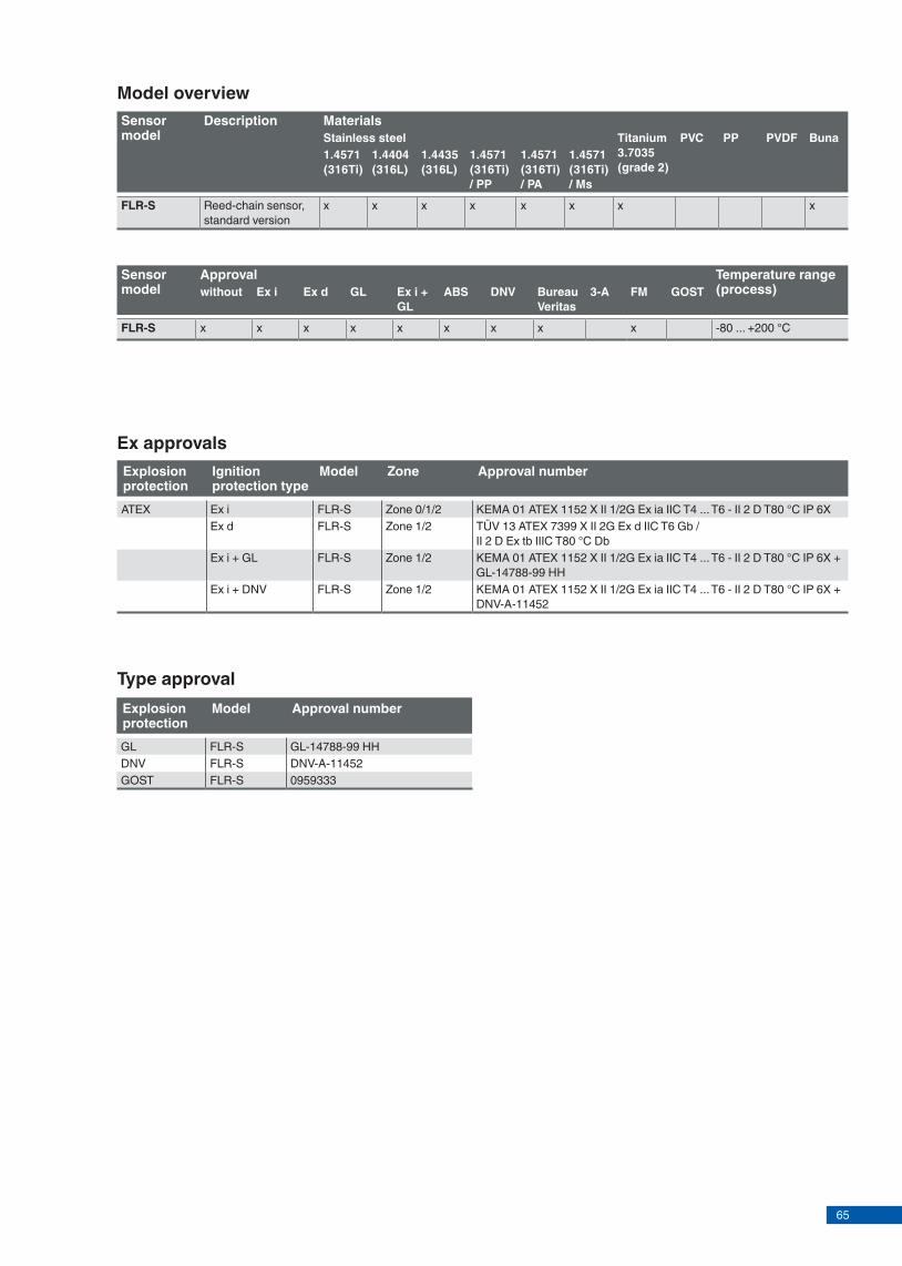
65
Further special features
■■ Large■scope■of■application■due■to■the■simple,■proven■functional■principle■■ Process■connection,■guide■tube■and■float■from■stainless■steel■1.4571■or■plastic■■ For■harsh■operating■conditions,■long■service■life■■ Continuous■measurement■of■levels,■independent■of■physical■and■chemical■changes■of■the■media■such■as:■Foaming,■conductivity,■dielectric,■pressure,■vacuum,■temperature,■vapours,■condensation,■bubble■formation,■boiling■effects,■density■change■■ Signal■transmission■over■long■distances■■ Simple■installation■and■commissioning,■onetime■calibration■only,■no■recalibration■necessary■■ Level■displayed■proportional■to■volume■or■height■■ High■repeatability■■ Interface■measurement■and■overall■level■from■∆■density■50■kg/m³■■ Level■sensors■with■reed-chain■technology■qualify■as■passive■electrical■equipment■in■accordance■with■DIN■IEC■60079-11■and■can■be■installed■in■“zone■1”■hazar-dous■areas■without■certification,■so■long■as■the■equipment■is■operated■in■a■certified■intrinsically■safe■circuit■with■a■minimum■explosion■protection■of■EEx■ib.
Internal circuit diagram of the reed sensors
brown blackblue/grey
Legend
Resistance
Reed■contact
Options
■■ Customised■solutions■■ Programmable■and■configurable■head-mounted■trans-mitters■in■connection■housing,■output■signal■4■...■20■mA,■2-wire,■for■HART®,■PROFIBUS®■PA■and■FOUNDATION™■Fieldbus■■ Process■connection,■guide■tube■material■and■float■from■stainless■steel■1.4435,■1.4539,■titanium,■Hastelloy■(others■on■request)■■ In■combination■with■limit■switch,■stepless■setting■of■the■limit■values■over■the■entire■measuring■range
Page■2■of■10 KSR■data■sheet■FLR■for■NPP■∙■04/2015
Model overview
Sensor model
Approval Temperature range(process)without Ex i Ex d GL Ex i +
GLABS DNV Bureau
Veritas3-A FM GOST
FLR-S x x x x x x x x x -80■...■+200■°C
Type approvalExplosion protection
Model Approval number
GL FLR-S GL-14788-99■HHDNV FLR-S DNV-A-11452GOST FLR-S 0959333
Ex approvalsExplosion protection
Ignition protection type
Model Zone Approval number
ATEX Ex■i FLR-S Zone■0/1/2 KEMA■01■ATEX■1152■X■II■1/2G■Ex■ia■IIC■T4■...■T6■-■II■2■D■T80■°C■IP■6XEx■d FLR-S Zone■1/2 TÜV■13■ATEX■7399■X■II■2G■Ex■d■IIC■T6■Gb■/■
II■2■D■Ex■tb■IIIC■T80■°C■DbEx■i■+■GL FLR-S Zone■1/2 KEMA■01■ATEX■1152■X■II■1/2G■Ex■ia■IIC■T4■...■T6■-■II■2■D■T80■°C■IP■6X■+■
GL-14788-99■HHEx■i■+■DNV FLR-S Zone■1/2 KEMA■01■ATEX■1152■X■II■1/2G■Ex■ia■IIC■T4■...■T6■-■II■2■D■T80■°C■IP■6X■+■
DNV-A-11452
Sensor model
Description MaterialsStainless steel Titanium
3.7035 (grade 2)
PVC PP PVDF Buna1.4571 (316Ti)
1.4404 (316L)
1.4435 (316L)
1.4571 (316Ti) / PP
1.4571 (316Ti) / PA
1.4571 (316Ti) / Ms
FLR-S Reed-chain■sensor,■standard■version
x x x x x x x x
Page■3■of■10KSR■data■sheet■FLR■for■NPP■∙■04/2015

66
Connection■cable
SW■22■or■SW■27
100■%■display
Guide■tube■length■L■■=■... L■1■=■...
100■%■■display
Guide■tube■length■L■■=■... L■1■=■...
M20x1.5
SW■30■or■SW■36
100■%■display
Guide■tube■length■L■■=■... L■1■=■...
M20■x■1.5
Mounting■flange
Sensor, standard version, model FLR-SProcess■connection,■guide■tube■material■and■float■from■stainless■steel■1.4571
Connection■housing
Connection■housing
Float■ØFloat■Ø Float■Ø
Mounting thread(without connection housing)
Mounting thread Flange
Electrical■connection Connection■cable■■PVC■ ■Silicone■ ■PUR
Connection■housing■ ■Aluminium■80■x■75■x■57■mm■ Option:■Polypropylene,■polyester,■stainless■steel
Process■connection Mounting■threadupwards
Mounting■threaddownwardsG■1■1/2"■or■G■2"
Mounting■flange■DIN■DN■50■...■DN■200,■PN■6■...■PN■100■ANSI■2"■...■8",■class■150■...■600G■3/8"■(others■on■
request)G■1/2"■(others■on■request)
Guide■tube■diameter 8■mm■ 12■or■14■mm
18■mm 8■mm 12■or■14■mm
18■mm 8■mm 12■or■14■mm
18■mm 30■mm
Guide■tube■length■L■max. 500■mm 3,000■mm 6,000■mm 500■mm 3,000■mm 6,000■mm 500■mm 3,000■mm 6,000■mm 15,000■mm
Float Material■stainless■steel■1.4571■(Option:■Buna,■titanium)Float■diameter■from■44■...■120■mmFloat■selection■depending■on■guide■tube■diameter■and■process■conditions
Max.■operating■pressure 80■bar,■see■table■for■floats■(K)■and■(Z)
Temperature■range■standard
PVC-/PUR■cable■ -10■...■+80■°CSilicone■cable■ -10■...■+120■°C
-20■...■+120■°COption:■ ■High-temperature■version:■+120■...■+200■°COption:■ ■Low-temperature■version:■■■-80■...■-20■°C
Contact■separation K■18■=■18■mm■(not■with■option■high■and■low■temperature■version)■K■15■=■15■mm■K■10■=■10■mm■K■5■■■=■■■5■mm
Overall■resistance■of■the■measuring■chain
Length■and■separation■dependent
Connection■cable■to■transmitter
3-wire,■screened
Mounting■position Vertical■±30°
Ingress■protection IP■65■per■EN■60529■/■lEC■60529
Materials Stainless■steel■1.4571,■1.4404,■1.4435,■1.4439,■titanium■3.7035■(grade■2),■Hastelloy■and■others■on■request
Page■4■of■10 KSR■data■sheet■FLR■for■NPP■∙■04/2015
Nuclear■qualified■plug■(Han®■7D)■on■request.
X
Sensor, explosion-protected version, intrinsically safe, model FLR-SKEMA■01■ATEX■1052■X■II■1/2G■Ex■ia■IIC■T4■...■T6■-■II■2■D■T80■°C■IP■6XProcess■connection,■guide■tube■and■float■from■stainless■steel■1.4571
Mounting thread Flange
Electrical■connection Connection■housing■ ■Aluminium■80■x■75■x■57■mm■ Option:■Stainless■steel,■polyester
Process■connection Mounting■threaddownwardsG■1■1/2"■or■G■2"■(others■on■request)
Mounting■flange■DIN■DN■50■...■DN■200,■PN■6■...■PN■100■ANSI■2"■...■8",■class■150■...■600
Guide■tube■diameter 12,■14■or■18■mm
Guide■tube■length■L■■■■max. See■variants■A■and■B■
Float Material■stainless■steel■1.4571■(Option:■Buna,■titanium)Float■diameter■from■44■...■120■mmFloat■selection■depending■on■guide■tube■diameter■and■process■conditions■
Max.■operating■pressure see■table■for■floats■(K)■and■(Z)
Temperature■class■■ Surface■temperature■■ Process■temperature■ Ambient■temperature■■■■ at■connection■housing
■■ T4■ T5■ T6Max.■■ 135■°C■ 100■°C■ 85■°CMax.■■ 100■°C■ 65■°C■ 50■°C
Max.■■ 60■°C■ 60■°C■ 60■°C
Contact■separation K■18■=■18■mmK■15■=■15■mm■K■10■=■10■mm■K■5■■■=■■■5■mm
Overall■resistance■of■the■measuring■chain
Length■and■separation■dependent
Control■circuit Ignition■protection■type■EEx■ia■IIC,■only■for■connection■to■a■certified■intrinsically■safe■control■circuit■■Transmitter■external■with■max.■120■mA,■max.■28■V■■Head-mounted■transmitter■in■accordance■with■transmitter■approvals
Connection■cable■to■transmitter
Cable■length■max.■2,000■m,■3-wire,■screened
Mounting■position Vertical■±30°
Ingress■protection IP■65■per■EN■60529■/■lEC■60529
Materials Stainless■steel■1.4571,■1.4404,■titanium■3.7035■(grade■2),■Hastelloy■and■others■on■request
Connection■housing
SW■30■and/or■SW■36
100■%■display
Guide■tube■length■L■■=■... L■1■=■...
100■%■display
Guide■tube■length■L■■=■... L■1■=■...
M20■x■1.5
Mounting■flange
Float■Ø Float■Ø
Connection■housing
M20■x■1.5
Page■5■of■10KSR■data■sheet■FLR■for■NPP■∙■04/2015
Nuclear■qualified■plug■(Han®■7D)■on■request.

67
Connection■cable
SW■22■or■SW■27
100■%■display
Guide■tube■length■L■■=■... L■1■=■...
100■%■■display
Guide■tube■length■L■■=■... L■1■=■...
M20x1.5
SW■30■or■SW■36
100■%■display
Guide■tube■length■L■■=■... L■1■=■...
M20■x■1.5
Mounting■flange
Sensor, standard version, model FLR-SProcess■connection,■guide■tube■material■and■float■from■stainless■steel■1.4571
Connection■housing
Connection■housing
Float■ØFloat■Ø Float■Ø
Mounting thread(without connection housing)
Mounting thread Flange
Electrical■connection Connection■cable■■PVC■ ■Silicone■ ■PUR
Connection■housing■ ■Aluminium■80■x■75■x■57■mm■ Option:■Polypropylene,■polyester,■stainless■steel
Process■connection Mounting■threadupwards
Mounting■threaddownwardsG■1■1/2"■or■G■2"
Mounting■flange■DIN■DN■50■...■DN■200,■PN■6■...■PN■100■ANSI■2"■...■8",■class■150■...■600G■3/8"■(others■on■
request)G■1/2"■(others■on■request)
Guide■tube■diameter 8■mm■ 12■or■14■mm
18■mm 8■mm 12■or■14■mm
18■mm 8■mm 12■or■14■mm
18■mm 30■mm
Guide■tube■length■L■max. 500■mm 3,000■mm 6,000■mm 500■mm 3,000■mm 6,000■mm 500■mm 3,000■mm 6,000■mm 15,000■mm
Float Material■stainless■steel■1.4571■(Option:■Buna,■titanium)Float■diameter■from■44■...■120■mmFloat■selection■depending■on■guide■tube■diameter■and■process■conditions
Max.■operating■pressure 80■bar,■see■table■for■floats■(K)■and■(Z)
Temperature■range■standard
PVC-/PUR■cable■ -10■...■+80■°CSilicone■cable■ -10■...■+120■°C
-20■...■+120■°COption:■ ■High-temperature■version:■+120■...■+200■°COption:■ ■Low-temperature■version:■■■-80■...■-20■°C
Contact■separation K■18■=■18■mm■(not■with■option■high■and■low■temperature■version)■K■15■=■15■mm■K■10■=■10■mm■K■5■■■=■■■5■mm
Overall■resistance■of■the■measuring■chain
Length■and■separation■dependent
Connection■cable■to■transmitter
3-wire,■screened
Mounting■position Vertical■±30°
Ingress■protection IP■65■per■EN■60529■/■lEC■60529
Materials Stainless■steel■1.4571,■1.4404,■1.4435,■1.4439,■titanium■3.7035■(grade■2),■Hastelloy■and■others■on■request
Page■4■of■10 KSR■data■sheet■FLR■for■NPP■∙■04/2015
Nuclear■qualified■plug■(Han®■7D)■on■request.
X
Sensor, explosion-protected version, intrinsically safe, model FLR-SKEMA■01■ATEX■1052■X■II■1/2G■Ex■ia■IIC■T4■...■T6■-■II■2■D■T80■°C■IP■6XProcess■connection,■guide■tube■and■float■from■stainless■steel■1.4571
Mounting thread Flange
Electrical■connection Connection■housing■ ■Aluminium■80■x■75■x■57■mm■ Option:■Stainless■steel,■polyester
Process■connection Mounting■threaddownwardsG■1■1/2"■or■G■2"■(others■on■request)
Mounting■flange■DIN■DN■50■...■DN■200,■PN■6■...■PN■100■ANSI■2"■...■8",■class■150■...■600
Guide■tube■diameter 12,■14■or■18■mm
Guide■tube■length■L■■■■max. See■variants■A■and■B■
Float Material■stainless■steel■1.4571■(Option:■Buna,■titanium)Float■diameter■from■44■...■120■mmFloat■selection■depending■on■guide■tube■diameter■and■process■conditions■
Max.■operating■pressure see■table■for■floats■(K)■and■(Z)
Temperature■class■■ Surface■temperature■■ Process■temperature■ Ambient■temperature■■■■ at■connection■housing
■■ T4■ T5■ T6Max.■■ 135■°C■ 100■°C■ 85■°CMax.■■ 100■°C■ 65■°C■ 50■°C
Max.■■ 60■°C■ 60■°C■ 60■°C
Contact■separation K■18■=■18■mmK■15■=■15■mm■K■10■=■10■mm■K■5■■■=■■■5■mm
Overall■resistance■of■the■measuring■chain
Length■and■separation■dependent
Control■circuit Ignition■protection■type■EEx■ia■IIC,■only■for■connection■to■a■certified■intrinsically■safe■control■circuit■■Transmitter■external■with■max.■120■mA,■max.■28■V■■Head-mounted■transmitter■in■accordance■with■transmitter■approvals
Connection■cable■to■transmitter
Cable■length■max.■2,000■m,■3-wire,■screened
Mounting■position Vertical■±30°
Ingress■protection IP■65■per■EN■60529■/■lEC■60529
Materials Stainless■steel■1.4571,■1.4404,■titanium■3.7035■(grade■2),■Hastelloy■and■others■on■request
Connection■housing
SW■30■and/or■SW■36
100■%■display
Guide■tube■length■L■■=■... L■1■=■...
100■%■display
Guide■tube■length■L■■=■... L■1■=■...
M20■x■1.5
Mounting■flange
Float■Ø Float■Ø
Connection■housing
M20■x■1.5
Page■5■of■10KSR■data■sheet■FLR■for■NPP■∙■04/2015
Nuclear■qualified■plug■(Han®■7D)■on■request.
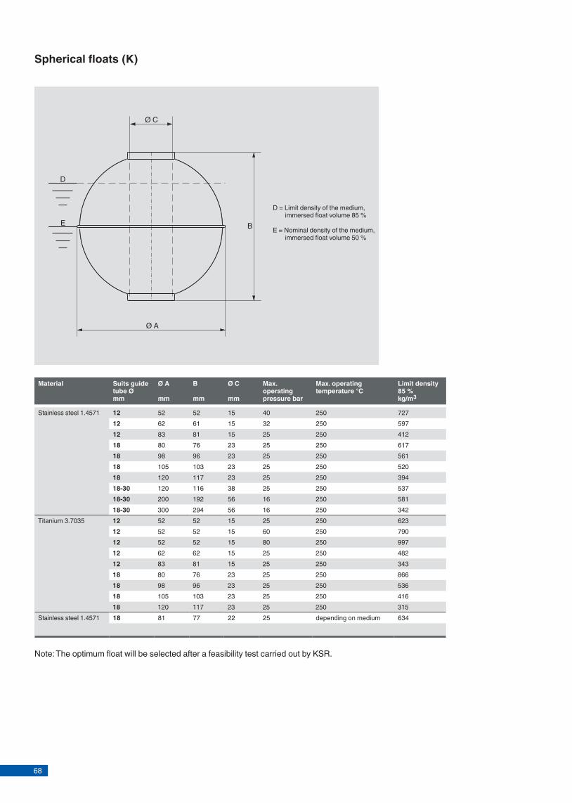
68
Material Suits guide tube Ø mm
Ø A mm
B mm
Ø C mm
Max. operating pressure bar
Max. operating temperature °C
Limit density 85 % kg/m3
Stainless■steel■1.4571 12 52 52 15 40 250 72712 62 61 15 32 250 59712 83 81 15 25 250 41218 80 76 23 25 250 61718 98 96 23 25 250 56118 105 103 23 25 250 52018 120 117 23 25 250 39418-30 120 116 38 25 250 53718-30 200 192 56 16 250 58118-30 300 294 56 16 250 342
Titanium■3.7035 12 52 52 15 25 250 62312 52 52 15 60 250 79012 52 52 15 80 250 99712 62 62 15 25 250 48212 83 81 15 25 250 34318 80 76 23 25 250 86618 98 96 23 25 250 53618 105 103 23 25 250 41618 120 117 23 25 250 315
Stainless■steel■1.4571 18 81 77 22 25 depending■on■medium 634
D■=■Limit■density■of■the■medium,■immersed■float■volume■85■%
E■=■Nominal■density■of■the■medium,■immersed■float■volume■50■%
Ø■A
Ø■C
D
E B
Spherical floats (K)
Note:■The■optimum■float■will■be■selected■after■a■feasibility■test■carried■out■by■KSR.
Page■6■of■10 KSR■data■sheet■FLR■for■NPP■∙■04/2015
Material Suits guide tube Ø mm
Ø A mm
B mm
Ø C mm
Max. operating pressure bar
Max. operating temperature °C
Limit density 85 % kg/m3
Stainless■steel■1.4571 12 44 52 15 16 250 740Titanium■3.7035 12 44 52 15 16 250 645
Ø■A
Ø■C
D
E B
Cylindrical floats (Z)
D■=■Limit■density■of■the■medium,■immersed■float■volume■85■%
E■=■Nominal■density■of■the■medium,■immersed■float■volume■50■%
Note:■The■optimum■float■will■be■selected■after■a■feasibility■test■carried■out■by■KSR.
Page■7■of■10KSR■data■sheet■FLR■for■NPP■∙■04/2015

69
Material Suits guide tube Ø mm
Ø A mm
B mm
Ø C mm
Max. operating pressure bar
Max. operating temperature °C
Limit density 85 % kg/m3
Stainless■steel■1.4571 12 52 52 15 40 250 72712 62 61 15 32 250 59712 83 81 15 25 250 41218 80 76 23 25 250 61718 98 96 23 25 250 56118 105 103 23 25 250 52018 120 117 23 25 250 39418-30 120 116 38 25 250 53718-30 200 192 56 16 250 58118-30 300 294 56 16 250 342
Titanium■3.7035 12 52 52 15 25 250 62312 52 52 15 60 250 79012 52 52 15 80 250 99712 62 62 15 25 250 48212 83 81 15 25 250 34318 80 76 23 25 250 86618 98 96 23 25 250 53618 105 103 23 25 250 41618 120 117 23 25 250 315
Stainless■steel■1.4571 18 81 77 22 25 depending■on■medium 634
D■=■Limit■density■of■the■medium,■immersed■float■volume■85■%
E■=■Nominal■density■of■the■medium,■immersed■float■volume■50■%
Ø■A
Ø■C
D
E B
Spherical floats (K)
Note:■The■optimum■float■will■be■selected■after■a■feasibility■test■carried■out■by■KSR.
Page■6■of■10 KSR■data■sheet■FLR■for■NPP■∙■04/2015
Material Suits guide tube Ø mm
Ø A mm
B mm
Ø C mm
Max. operating pressure bar
Max. operating temperature °C
Limit density 85 % kg/m3
Stainless■steel■1.4571 12 44 52 15 16 250 740Titanium■3.7035 12 44 52 15 16 250 645
Ø■A
Ø■C
D
E B
Cylindrical floats (Z)
D■=■Limit■density■of■the■medium,■immersed■float■volume■85■%
E■=■Nominal■density■of■the■medium,■immersed■float■volume■50■%
Note:■The■optimum■float■will■be■selected■after■a■feasibility■test■carried■out■by■KSR.
Page■7■of■10KSR■data■sheet■FLR■for■NPP■∙■04/2015
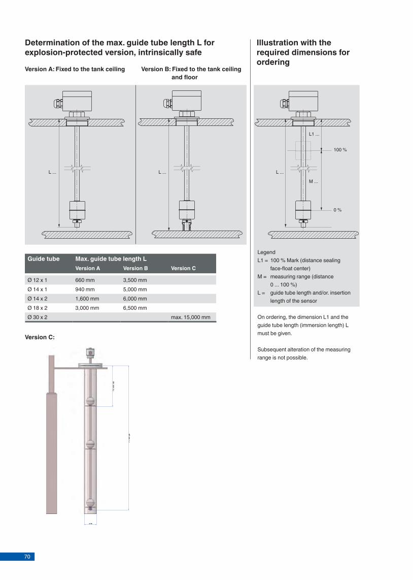
70
Guide tube Max. guide tube length LVersion A Version B Version C
Ø■12■x■1 660■mm 3,500■mmØ■14■x■1 940■mm 5,000■mmØ■14■x■2 1,600■mm 6,000■mmØ■18■x■2 3,000■mm 6,500■mmØ■30■x■2 max.■15,000■mm
Determination of the max. guide tube length L for explosion-protected version, intrinsically safe
Version A: Fixed to the tank ceiling Version B: Fixed to the tank ceiling and fl oor
L■... L■...
L1■...
M■...
100■%■
0■%
LegendL1■=■ 100■%■Mark■(distance■sealing■
face-fl■oat■center)M■=■■ measuring■range■(distance■
0■...■100■%)L■=■■ guide■tube■length■and/or.■insertion■
length■of■the■sensor
On■ordering,■the■dimension■L1■and■the■guide■tube■length■(immersion■length)■L■must■be■given.
Subsequent■alteration■of■the■measuring■range■is■not■possible.
Illustration with the required dimensions for ordering
L■...
Page■8■of■10 KSR■data■sheet■FLR■for■NPP■∙■04/2015
Version C:
■
PLC■or■display
PLC■or■display
Transmitter■power■supply
Transmitter■or■gate
Control■room
Interface■layer
PLC■or■display■(non-Ex)
Transmitter
Transmitter■power■supply■(Ex)
4■...■20■mA■not■intrinsically■safe
Resistance
PLC■or■display■(Ex■or■non-Ex)
non-ExEx*
PLC■or■display■(non-Ex)
Transmitter■
4■...■20■mAnot■intrinsically■safe
Resistance
All■level■sensors■from■metal■or■anti-static■plastic
4■...■20■mA■not■intrinsically■safecontrol■room
in■containment
0■ 500■ 1,000■ 1,500■ 2,000■ 2,500■ 3,000■ 3,500■ 4,000■ 4,500■ 5,000■ 5,500■ 6,000
10.0■%
1.0■%
0.1■%
Application examplesStandard applications Connection to bus systems
Resistance
4■...■20■mA
4■...■20■mA
Applications for nuclear power plantsApplications for Ex-Zone 0
Measuring accuracy
LegendK■18■ Contact■separation■18■mmK■15■ Contact■separation■15■mmK■10■ Contact■separation■10■mmK■5■ Contact■separation■■5■mm
Measuring■range■in■mm
Option:■built-in■head-mounted■transmitter
Option:■built-in■head-mounted■transmitters
Fieldbuse.g.■FOUNDATION™■Fieldbus
Option:■built-in■head-mounted■transmitter
Transmitter
Resistance
Product■layer
Sensor
*only■for■Ex-Zone■1■or■2
*Ex-Zone■0■in■vessel
K■18K■15K■10K■5
Page■9■of■10KSR■data■sheet■FLR■for■NPP■∙■04/2015
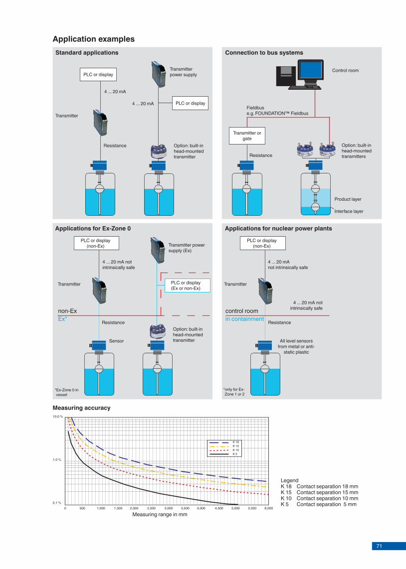
71
Guide tube Max. guide tube length LVersion A Version B Version C
Ø■12■x■1 660■mm 3,500■mmØ■14■x■1 940■mm 5,000■mmØ■14■x■2 1,600■mm 6,000■mmØ■18■x■2 3,000■mm 6,500■mmØ■30■x■2 max.■15,000■mm
Determination of the max. guide tube length L for explosion-protected version, intrinsically safe
Version A: Fixed to the tank ceiling Version B: Fixed to the tank ceiling and fl oor
L■... L■...
L1■...
M■...
100■%■
0■%
LegendL1■=■ 100■%■Mark■(distance■sealing■
face-fl■oat■center)M■=■■ measuring■range■(distance■
0■...■100■%)L■=■■ guide■tube■length■and/or.■insertion■
length■of■the■sensor
On■ordering,■the■dimension■L1■and■the■guide■tube■length■(immersion■length)■L■must■be■given.
Subsequent■alteration■of■the■measuring■range■is■not■possible.
Illustration with the required dimensions for ordering
L■...
Page■8■of■10 KSR■data■sheet■FLR■for■NPP■∙■04/2015
Version C:
■
PLC■or■display
PLC■or■display
Transmitter■power■supply
Transmitter■or■gate
Control■room
Interface■layer
PLC■or■display■(non-Ex)
Transmitter
Transmitter■power■supply■(Ex)
4■...■20■mA■not■intrinsically■safe
Resistance
PLC■or■display■(Ex■or■non-Ex)
non-ExEx*
PLC■or■display■(non-Ex)
Transmitter■
4■...■20■mAnot■intrinsically■safe
Resistance
All■level■sensors■from■metal■or■anti-static■plastic
4■...■20■mA■not■intrinsically■safecontrol■room
in■containment
0■ 500■ 1,000■ 1,500■ 2,000■ 2,500■ 3,000■ 3,500■ 4,000■ 4,500■ 5,000■ 5,500■ 6,000
10.0■%
1.0■%
0.1■%
Application examplesStandard applications Connection to bus systems
Resistance
4■...■20■mA
4■...■20■mA
Applications for nuclear power plantsApplications for Ex-Zone 0
Measuring accuracy
LegendK■18■ Contact■separation■18■mmK■15■ Contact■separation■15■mmK■10■ Contact■separation■10■mmK■5■ Contact■separation■■5■mm
Measuring■range■in■mm
Option:■built-in■head-mounted■transmitter
Option:■built-in■head-mounted■transmitters
Fieldbuse.g.■FOUNDATION™■Fieldbus
Option:■built-in■head-mounted■transmitter
Transmitter
Resistance
Product■layer
Sensor
*only■for■Ex-Zone■1■or■2
*Ex-Zone■0■in■vessel
K■18K■15K■10K■5
Page■9■of■10KSR■data■sheet■FLR■for■NPP■∙■04/2015

72
KSR KUEBLER Niveau-Messtechnik AGHeinrich-Kuebler-Platz■169439■Zwingenberg/GermanyTel.■ +49■6263■87-0Fax■ +49■6263■[email protected]
©■2014■KSR■KUEBLER■Niveau-Messtechnik■AG,■all■rights■reserved.The■specifi■cations■given■in■this■document■represent■the■state■of■engineering■at■the■time■of■publishing.We■reserve■the■right■to■make■modifi■cations■to■the■specifi■cations■and■materials.
Head-mounted transmitter
Model 4 ... 20 mA HART® PROFIBUS® PA Fieldbus™ Exi IEEE Display
TE x x x
TS x
T32E x x x
T32S x x
T53F x x
T53P x x
TLH x x x
TLEH x x x x
Model T53F Model TLEHModel TE Model T32E
Page■10■of■10 KSR■data■sheet■FLR■for■NPP■∙■04/2015
04/2015■EN
Level measurement
Optoelectronic level switchModel OLS-H / OLS-H-HT high-temperature For nuclear power plants
Fig. left: Optoelectronic level switch, model OLS-HFig. right: Switching amplifi er, model OSA-S, aluminum add-on case
Applications
■ Chemical, petrochemical, natural gas, off shore industries ■ Shipbuilding, machine building, refrigerator units ■ Power generating equipment, power plants ■ Process and drinking water treatment ■ Wastewater and environmental engineering
Special features
■ Temperature ranges from 0 … +350 °C ■ Pressure up to 176 bar ■ Signal processing is made using a separate model OSA-S
switching amplifi er
Description
The model OLS optoelectronic level switches are used for the detection of limit levels in liquids. This is widely indepen-dent of physical characteristics such as refractive index, colour, density, dielectric constant and conductivity. Measure-ment is also done in small volumes.
The switches consist of an infrared LED and a phototransi-stor. The light of the LED is directed into a prism. So long as the sensor tip of the prism is in the gas phase, the light is refl ected within the prism to the receiver. When the liquid in the vessel rises and wets approximately 2/3 of the glass tip, the infrared lightbeam into the liquid is interrupted and only a small portion reaches the receiver. This diff erence is evalua-ted by the electronics and triggers a switching operation.
The instruments are very robust and designed for rough operating conditions.
KSR data sheet OLS-H for NPP
Page 1 of 4KSR data sheet OLS-H for NPP∙ 04/2015

73
KSR KUEBLER Niveau-Messtechnik AGHeinrich-Kuebler-Platz■169439■Zwingenberg/GermanyTel.■ +49■6263■87-0Fax■ +49■6263■[email protected]
©■2014■KSR■KUEBLER■Niveau-Messtechnik■AG,■all■rights■reserved.The■specifi■cations■given■in■this■document■represent■the■state■of■engineering■at■the■time■of■publishing.We■reserve■the■right■to■make■modifi■cations■to■the■specifi■cations■and■materials.
Head-mounted transmitter
Model 4 ... 20 mA HART® PROFIBUS® PA Fieldbus™ Exi IEEE Display
TE x x x
TS x
T32E x x x
T32S x x
T53F x x
T53P x x
TLH x x x
TLEH x x x x
Model T53F Model TLEHModel TE Model T32E
Page■10■of■10 KSR■data■sheet■FLR■for■NPP■∙■04/2015
04/2015■EN
Level measurement
Optoelectronic level switchModel OLS-H / OLS-H-HT high-temperature For nuclear power plants
Fig. left: Optoelectronic level switch, model OLS-HFig. right: Switching amplifi er, model OSA-S, aluminum add-on case
Applications
■ Chemical, petrochemical, natural gas, off shore industries ■ Shipbuilding, machine building, refrigerator units ■ Power generating equipment, power plants ■ Process and drinking water treatment ■ Wastewater and environmental engineering
Special features
■ Temperature ranges from 0 … +350 °C ■ Pressure up to 176 bar ■ Signal processing is made using a separate model OSA-S
switching amplifi er
Description
The model OLS optoelectronic level switches are used for the detection of limit levels in liquids. This is widely indepen-dent of physical characteristics such as refractive index, colour, density, dielectric constant and conductivity. Measure-ment is also done in small volumes.
The switches consist of an infrared LED and a phototransi-stor. The light of the LED is directed into a prism. So long as the sensor tip of the prism is in the gas phase, the light is refl ected within the prism to the receiver. When the liquid in the vessel rises and wets approximately 2/3 of the glass tip, the infrared lightbeam into the liquid is interrupted and only a small portion reaches the receiver. This diff erence is evalua-ted by the electronics and triggers a switching operation.
The instruments are very robust and designed for rough operating conditions.
KSR data sheet OLS-H for NPP
Page 1 of 4KSR data sheet OLS-H for NPP∙ 04/2015
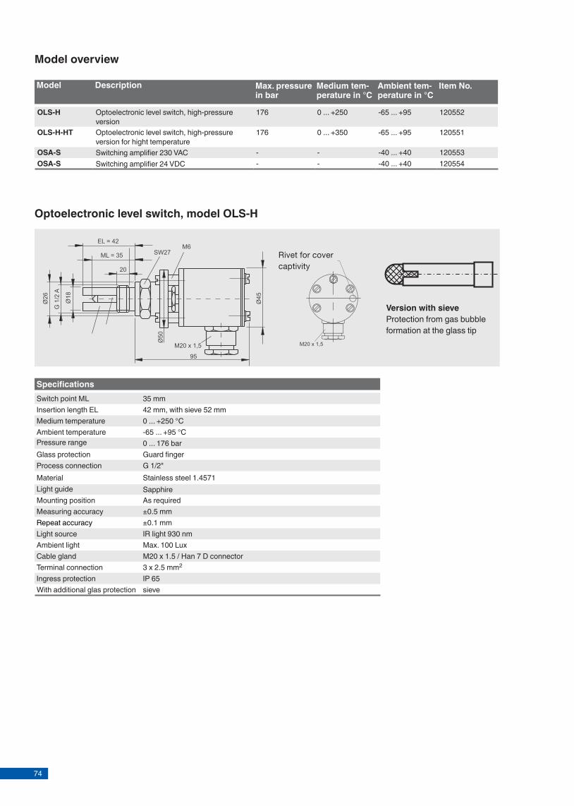
74
Model overview
Model Description Max. pressure in bar
Medium tem-perature in °C
Ambient tem-perature in °C
Item No.
OLS-H Optoelectronic level switch, high-pressure version
176 0 ... +250 -65 ... +95 120552
OLS-H-HT Optoelectronic level switch, high-pressure version for hight temperature
176 0 ... +350 -65 ... +95 120551
OSA-S Switching amplifier 230 VAC - - -40 ... +40 120553OSA-S Switching amplifier 24 VDC - - -40 ... +40 120554
Page 2 of 4 KSR data sheet OLS-H for NPP ∙ 04/2015
EL
= 42
ML
= 35
SW27M6
EL = 42
ML = 35Ø
45
Ø18
Ø26
G 1
/2 A
M20 x 1,5
95
20
Ø50
M20 x 1,5
EL
= 42
ML
= 35
SW27M6
EL = 42
ML = 35
Ø45
Ø18
Ø26
G 1
/2 A
M20 x 1,5
95
20
Ø50
M20 x 1,5
SpecificationsSwitch point ML 35 mmInsertion length EL 42 mm, with sieve 52 mmMedium temperature 0 ... +250 °CAmbient temperature -65 ... +95 °CPressure range 0 ... 176 barGlass protection Guard fingerProcess connection G 1/2"Material Stainless steel 1.4571Light guide SapphireMounting position As requiredMeasuring accuracy ±0.5 mmRepeat accuracy ±0.1 mmLight source IR light 930 nmAmbient light Max. 100 LuxCable gland M20 x 1.5 / Han 7 D connectorTerminal connection 3 x 2.5 mm2
Ingress protection IP 65With additional glas protection sieve
Optoelectronic level switch, model OLS-H
Version with sieveProtection from gas bubble formation at the glass tip
Rivet for covercaptivity
G 1/2 A
Ø26
Ø18
Ø16
Ø7
ML (max. 960 mm)SW27
M20 x 1,5
151
EL
Cooling fin
Specification: with cooling finTemperature range 0 ... +350 °CAmbient temperature -65 ... +95 °C
Electrical connection diagram
brown
green
white
Option for high-temperature
Page 3 of 4 KSR data sheet OLS-H for NPP ∙ 04/2015
Optoelectronic level switch, model OLS-H-HT

75
Model overview
Model Description Max. pressure in bar
Medium tem-perature in °C
Ambient tem-perature in °C
Item No.
OLS-H Optoelectronic level switch, high-pressure version
176 0 ... +250 -65 ... +95 120552
OLS-H-HT Optoelectronic level switch, high-pressure version for hight temperature
176 0 ... +350 -65 ... +95 120551
OSA-S Switching amplifier 230 VAC - - -40 ... +40 120553OSA-S Switching amplifier 24 VDC - - -40 ... +40 120554
Page 2 of 4 KSR data sheet OLS-H for NPP ∙ 04/2015
EL
= 42
ML
= 35
SW27M6
EL = 42
ML = 35
Ø45
Ø18
Ø26
G 1
/2 A
M20 x 1,5
95
20
Ø50
M20 x 1,5
EL
= 42
ML
= 35
SW27M6
EL = 42
ML = 35
Ø45
Ø18
Ø26
G 1
/2 A
M20 x 1,5
95
20
Ø50
M20 x 1,5
SpecificationsSwitch point ML 35 mmInsertion length EL 42 mm, with sieve 52 mmMedium temperature 0 ... +250 °CAmbient temperature -65 ... +95 °CPressure range 0 ... 176 barGlass protection Guard fingerProcess connection G 1/2"Material Stainless steel 1.4571Light guide SapphireMounting position As requiredMeasuring accuracy ±0.5 mmRepeat accuracy ±0.1 mmLight source IR light 930 nmAmbient light Max. 100 LuxCable gland M20 x 1.5 / Han 7 D connectorTerminal connection 3 x 2.5 mm2
Ingress protection IP 65With additional glas protection sieve
Optoelectronic level switch, model OLS-H
Version with sieveProtection from gas bubble formation at the glass tip
Rivet for covercaptivity
G 1/2 A
Ø26
Ø18
Ø16
Ø7
ML (max. 960 mm)SW27
M20 x 1,5
151
EL
Cooling fin
Specification: with cooling finTemperature range 0 ... +350 °CAmbient temperature -65 ... +95 °C
Electrical connection diagram
brown
green
white
Option for high-temperature
Page 3 of 4 KSR data sheet OLS-H for NPP ∙ 04/2015
Optoelectronic level switch, model OLS-H-HT
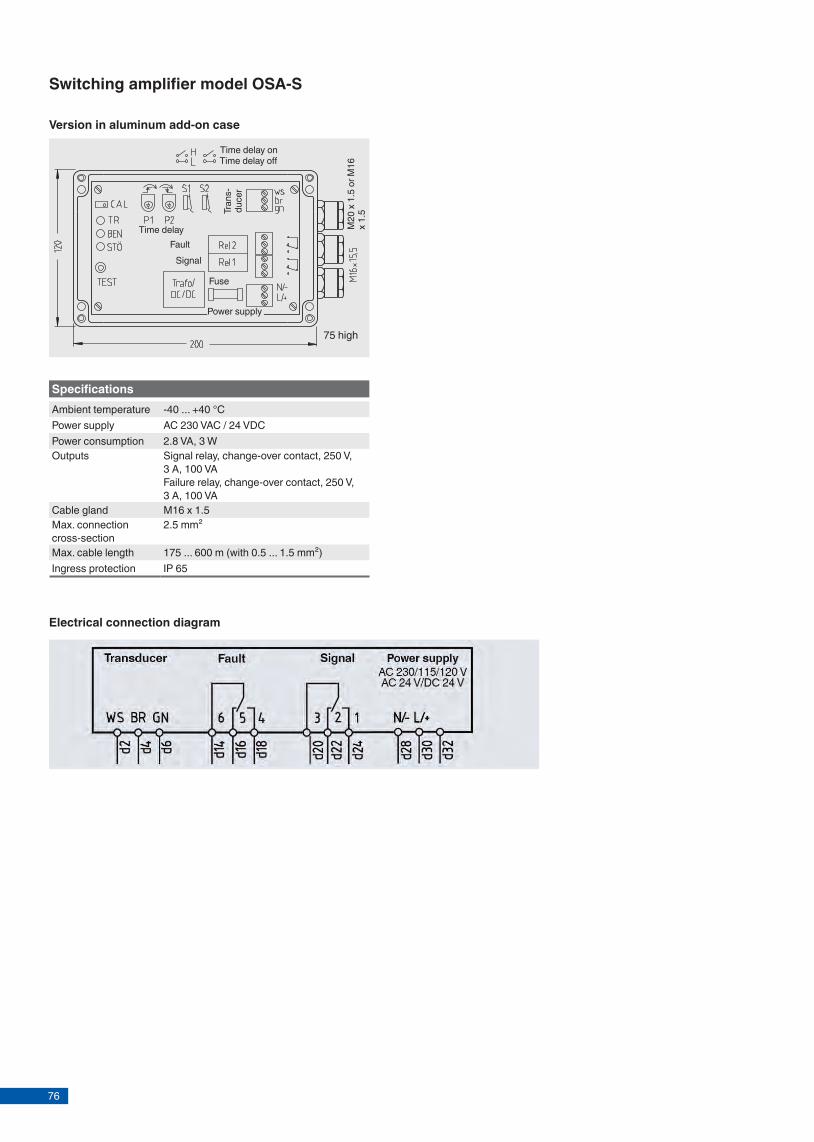
76
KSR KUEBLER Niveau-Messtechnik AGHeinrich-Kuebler-Platz 169439 Zwingenberg/GermanyTel. +49 6263 87-0Fax +49 6263 [email protected]
Electrical connection diagram
© 2015 KSR KUEBLER Niveau-Messtechnik AG, all rights reserved.The specifi cations given in this document represent the state of engineering at the time of publishing.We reserve the right to make modifi cations to the specifi cations and materials.
KSR data sheet OLS-H for NPP ∙ 04/2015Page 4 of 4
04/2
015
EN
Version in aluminum add-on case
Tran
s-du
cer
75 high
Fuse
M20
x 1
.5 o
r M16
x
1.5
Time delay onTime delay off
Time delayFault
Signal
Specifi cationsAmbient temperature -40 ... +40 °CPower supply AC 230 VAC / 24 VDCPower consumption 2.8 VA, 3 WOutputs Signal relay, change-over contact, 250 V,
3 A, 100 VAFailure relay, change-over contact, 250 V, 3 A, 100 VA
Cable gland M16 x 1.5 Max. connection cross-section
2.5 mm²
Max. cable length 175 ... 600 m (with 0.5 ... 1.5 mm²)Ingress protection IP 65
Power supply
Switching amplifi er model OSA-S

77
KSR KUEBLER Niveau-Messtechnik AGHeinrich-Kuebler-Platz 169439 Zwingenberg/GermanyTel. +49 6263 87-0Fax +49 6263 [email protected]
Electrical connection diagram
© 2015 KSR KUEBLER Niveau-Messtechnik AG, all rights reserved.The specifi cations given in this document represent the state of engineering at the time of publishing.We reserve the right to make modifi cations to the specifi cations and materials.
KSR data sheet OLS-H for NPP ∙ 04/2015Page 4 of 4
04/2
015
EN
Version in aluminum add-on case
Tran
s-du
cer
75 high
Fuse
M20
x 1
.5 o
r M16
x
1.5
Time delay onTime delay off
Time delayFault
Signal
Specifi cationsAmbient temperature -40 ... +40 °CPower supply AC 230 VAC / 24 VDCPower consumption 2.8 VA, 3 WOutputs Signal relay, change-over contact, 250 V,
3 A, 100 VAFailure relay, change-over contact, 250 V, 3 A, 100 VA
Cable gland M16 x 1.5 Max. connection cross-section
2.5 mm²
Max. cable length 175 ... 600 m (with 0.5 ... 1.5 mm²)Ingress protection IP 65
Power supply
Switching amplifi er model OSA-S
Sales locations
Manufacturing facilities
KSR worldwide
France UKChina USA
India Canada Brazil
KUBLER France SA Shanghai KSR Kuebler Auto-mation Instrument Co. Ltd.
TC Fluid Control
WIKA Instruments India Pvt. Ltd.
WIKA Instruments Ltd - Canada Headquarters
WIKA DO BRASIL
WIKA Instrument -Houston Facility
South Africa
WIKA Instruments (Pty) Ltd.
Further manufacturing facilities

78

79
A division of the WIKA Group
KSR KUEBLERNiveau-Messtechnik AGHeinrich-Kuebler-Platz 169439 Zwingenberg am NeckarGermanyPhone: +49 (0) 6263 87-0Fax: +49 (0) 6263 [email protected]
04/2016
© 2015 KSR KUEBLER Niveau-Messtechnik AG, all rights reserved.The specifications given in this document represent the state of engineering at the time of publishing.We reserve the right to make modifications to the specifications and materials.