Embed Size (px)
Citation preview
Lessons from Developing and Deploying the Cricket IndoorLocation System
Hari Balakrishnan, Roshan Baliga, Dorothy Curtis, Michel Goraczko, Allen Miu,Bodhi Priyantha, Adam Smith, Ken Steele, Seth Teller, Kevin Wang
MIT Computer Science and Artificial Intelligence Laboratory (CSAIL)http://nms.lcs.mit.edu/cricket/
November 7, 2003
AbstractThe Cricket indoor location project has been active forfour years. We have developed three different versionsof the system. The first version was an early proof-of-concept (Cricket v0), which led to the first prototype(Cricket v1). Cricket v1 has seen extensive use by us andby a few other research groups in the community. Dur-ing this time, we have learned a number of lessons fromapplication designers, users, and system maintainers. Webreak these lessons into platform flexibility, where we dis-cuss the Cricket API, embedded software platform, andhardware interfaces; location accuracy, where we dis-cuss Cricket v1’s performance and limitations, and de-ployment issues, where we discuss energy consumptionand system management. We discuss how these lessonshave helped improve the design of the next generation ofCricket, Cricket v2, whose key features we detail. LikeCricket v1, the Cricket v2 hardware design and softwarewill be released as open-source; v2 units will also be com-mercially available by early 2004. We believe that thelessons described in this paper will be useful to peopleinterested in building or using indoor location systems.
1 IntroductionIn Fall 1999, we started work on the design and imple-mentation of the Cricket indoor location system, moti-vated by the importance of mobile and context-aware ap-plications in pervasive computing environments and thepoor indoor performance of the Global Positioning Sys-tem (GPS). The first version of our system, Cricket v0,was a proof-of-concept research prototype [13]. As westarted deploying Cricket and obtaining users, we imple-mented a number of refinements and enhancements, lead-ing to several different subversions of Cricket v1. We dis-seminated Cricket v1 units to a few groups within and out-side MIT for research and educational purposes. This pro-cess occurred over nearly three years, during which time
we learned a number of lessons from the different uses towhich the system was put.
This paper documents these lessons, presented as acombination of practical anecdotes and quantitative ex-perimental data. We hope that our experience will be use-ful to people interested in either using or building indoorlocation systems in the future. We have organized thelessons into three broad categories:
1. Platform flexibility. Cricket was used in severalways that we had not envisioned in the original de-sign. These uses led to our understanding differ-ent types of useful location information, a softwareAPI encompassing this information, and appropriatehardware interfaces (Section 3).
2. Location accuracy. Many applications require ac-curate location information and do not handle errorswell. In particular, many applications do not copewell with high variance in reported location. We dis-cuss our efforts to improve location accuracy and re-duce variance (Section 4).
3. Deployment and management. Users generally ap-proved of Cricket’s decentralized deployment model,which allowed them to quickly deploy a small-scaleCricket system and get going. However, Cricketv1’s energy consumption and configuration meth-ods taught us that there was significant room for im-provement before long-term production use becamefeasible (Section 5).
We have attempted to be balanced in our evaluation ofCricket’s design decisions, but apologize for any overlydefensive comments! At this stage, it would be prema-ture to write a definitive paper on the lessons learned fromthe project, because it is still ongoing and we don’t yethave enough serious users. This paper should thereforebe viewed as a status report and as a summary of whatCricket v1 did right and wrong in our estimation.
In Spring 2003, we incorporated these lessons into thedesign process for the next generation system, Cricket v2.
1
We discuss how Cricket v2’s design addresses most of theobserved shortcomings of the previous version. The hard-ware design and software for Cricket v2 will be freelyavailable on the Cricket project’s Web site, and units willbe available for sale by early 2004.
2 Cricket OverviewThe original design of Cricket was motivated by fourgoals:
1. Scalability: Our goal was to scale well to large num-bers and high densities of devices requiring locationinformation.
2. Privacy: We wanted a system that would make ithard to track users, avoiding the user privacy prob-lem inherent in previous location systems (e.g., Xe-rox PARC’s pioneering Active Badge system [24,11]).
3. Low cost: We wanted to build devices from com-mercial off-the-shelf components, at a cost of tens,rather than hundreds, of dollars.
4. Accurate space detection: At first we were inter-ested only in accurately demarcating boundaries be-tween application-defined spaces (typically rooms orparts of rooms), which is sufficient for many appli-cations (e.g., resource discovery).
Our goals led us to an architecture that was radicallydifferent from existing indoor location systems like theActive Badge or Active Bat [6], which use passive ceiling-mounted receivers that obtain information from activetransmitters carried by users. The Cricket architecture“inverts” the architecture of the Active Badge and ActiveBat systems; in Cricket, ceiling or wall-mounted activebeacons send periodic chirps on a radio frequency (RF)channel, providing location information to passive listen-ers.
The listener attached to a host device (e.g., mobilehandheld, portable laptop, sensor, etc.) estimates its dis-tance from each beacon it hears, and uses these distancesto infer its location. Each beacon sends an ultrasonic (US)pulse at the same time as the RF message; the listener usesthe standard “time difference of arrival” technique by ob-serving the time lag between the arrival of the RF and USsignals, to estimate its distance from the beacon.
Qualitatively, the Cricket architecture offers the follow-ing advantages:
+ Good scalability. The RF and US channel use is in-dependent of the number of listening devices in anyregion; when host devices actively transmit, high-density deployments are harder to achieve.
+ Ease of deployment. Cricket beacons are easy to de-ploy; they do not require any infrastructure connect-ing them back to a base station, and can be placed
with few constraints inside rooms, open areas andcorridors.
+ User privacy. Cricket’s architecture allows a hostdevice to infer its location without the infrastructureor any other entity learning that information. WhileCricket by itself cannot guarantee user privacy, itmakes centralized tracking of users hard.
These advantages come at some cost:
− Continuous tracking is harder. In Cricket, a lis-tener hears only one beacon at a time. Updating theposition of a moving device is more complex thanin a system that simultaneously obtains multiple dis-tance estimates from the device to known positions.
− Beacon scheduling requires a distributed scheme.Cricket requires a distributed beacon schedulingscheme to avoid RF and US collisions at the listen-ers.
− Energy consumption is potentially higher. Activebeacons tend to consume more energy than passiveceiling-mounted receivers. However, both architec-tures require the transmitters or receivers distributedin the infrastructure to be powered somehow.
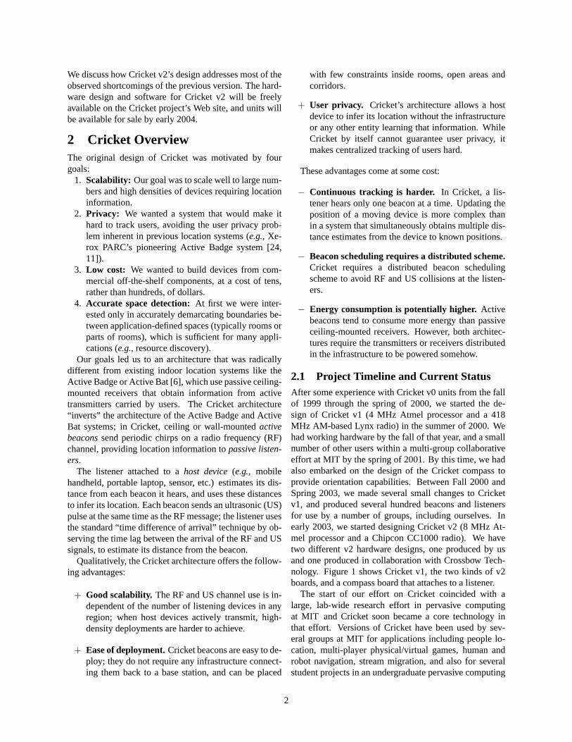
2.1 Project Timeline and Current StatusAfter some experience with Cricket v0 units from the fallof 1999 through the spring of 2000, we started the de-sign of Cricket v1 (4 MHz Atmel processor and a 418MHz AM-based Lynx radio) in the summer of 2000. Wehad working hardware by the fall of that year, and a smallnumber of other users within a multi-group collaborativeeffort at MIT by the spring of 2001. By this time, we hadalso embarked on the design of the Cricket compass toprovide orientation capabilities. Between Fall 2000 andSpring 2003, we made several small changes to Cricketv1, and produced several hundred beacons and listenersfor use by a number of groups, including ourselves. Inearly 2003, we started designing Cricket v2 (8 MHz At-mel processor and a Chipcon CC1000 radio). We havetwo different v2 hardware designs, one produced by usand one produced in collaboration with Crossbow Tech-nology. Figure 1 shows Cricket v1, the two kinds of v2boards, and a compass board that attaches to a listener.
The start of our effort on Cricket coincided with alarge, lab-wide research effort in pervasive computingat MIT and Cricket soon became a core technology inthat effort. Versions of Cricket have been used by sev-eral groups at MIT for applications including people lo-cation, multi-player physical/virtual games, human androbot navigation, stream migration, and also for severalstudent projects in an undergraduate pervasive computing
2
Figure 1: A few different Cricket units. From left to right: v1, v2, v2 done jointly with Crossbow, and a compass daughterboard. The T-shape of the new v2 units enables them to fit into a compact flash (CF) slot on a handheld or laptop. The v1and v2 units can function as either beacons or listeners.
course. We have also offered Cricket courses, held at MITand in elsewhere.
In addition to groups at MIT we have distributedCricket units to researchers elsewhere, including NTTLabs, Nokia Research, Delta Electronics, the Acer group,Crossbow Technology, Rutgers University, University ofWashington, Intel Research, Philips Research, and HPLabs (in addition to using our hardware, the last two havealso made their own versions with different radios). Wehave had over a hundred requests from other potentialusers for Cricket devices, requests that we have been un-able to satisfy with our limited production capability.
Our experiences with users and applications has in-formed our design of Cricket v2. For example, some ap-plications require spatial information, some require fine-grained, GPS-style position coordinates, and some bene-fit from orientation in addition to position. In addition,location-aware applications are not restricted to mobilehandhelds or laptops—many embedded sensor networksystems and applications require location information aswell.
2.2 Some Cricket ApplicationsThis subsection describes some of the applications thatpeople have built using Cricket. This is not an exhaus-tive list, but is intended to convey the diversity of appli-cations and point out limitations in previous (sub)versionsof Cricket.
2.2.1 Applications using “space” ID alone
The first class of applications uses only information aboutthe space (e.g., the room, or part of a room) that the mobiledevice is currently in. These applications rely on Cricket’sability to demarcate physical and virtual boundaries be-
tween spaces. Each beacon periodically broadcasts itsspace name on Cricket’s RF channel. Any listener devicereports the nearest beacon it hears. We found the spaceabstraction useful in several applications.
Resource discovery. Our first Cricket application waslocation-aware resource discovery, which we prototypedin conjunction with a separate resource discovery sys-tem. The goal is to find resources based on attribute-valuequeries, and have The discover system perform the match-ing between queries and resource advertisements. Loca-tion, obtained using Cricket, is an important attribute, be-cause users often care about obtaining access to resourcesnear where they are.
Pervasive Access Control. A student at MIT devel-oped a pervasive access control system, PAC, using thecoarse-grained location information provided by Cricket.This system provides light-weight access control basedon location, while preserving the user’s anonymity. Forexample, this infrastructure allows a service to be builtso that the ability to remotely control a room’s projec-tion or lighting system would be honored only for userswho could prove that they are currently close to that re-source. To implement this secure location subsystem,he assigned each beacon a location id (LID) and a LID-CODE, a pseudo-random number based on a seed. TheLIDCODE changes every minute in pseudo-random fash-ion, and the beacon periodically transmits its LID andLIDCODE. A device can present the appropriate LID-CODE to a server only if it is near the concerned space(or if someone near the space gives it the code).
Person locator. The person locator has two com-ponents: an application running on a handheld deviceequipped with a Cricket listener and a wireless networkcard, carried by each person, and a central server that can
3
be queried via a Web or conversational speech interface.When the application on the handheld device detects thatthe user has moved to a new location (i.e., when the iden-tity of the closest beacon changes), it securely updates theuser’s location on the server. The user can control when,and if, their handheld reports their location. The user canalso set preferences on the server to determine the level ofdetail reported based on their location and the identity ofthe person making the query.
Stream migration. Three different stream migrationservices have been built with Cricket. The first, migratesa live video conference to the best available display/soundresource.
The application uses Cricket to detect transitions intorooms where video conferencing resources are available,at which time the video and audio streams are migratedfrom the handheld device to a more suitable device in theroom. When the user leaves the room, the video confer-ence is migrated back to the handheld. The applicationdevelopers found that simply using the nearest beacon todetermine room identity was not sufficiently stable. Onenoisy sample could make a beacon in the hallway appearclosest when the user was in fact in the room. This wouldcause video to start migrating to the handheld, then im-mediately back to the room. Two other stream migrationsystems implemented with Cricket faced the same loca-tion stability issues: audio stream migration [14] and livetelevision migration [15].
It turned out that these and other application writerswanted access to the information provided by the beaconsheard by the listener, in order to implement application-specific filtering and hysteresis. With this information,they were able to make application-specific tradeoffs be-tween stability and responsiveness. As expected, the moresamples used for averaging the more stable the system is,but it then takes longer to recognize that a new room hasbeen entered. In Section 3, we discuss how this experi-ence was reflected in the Cricket API.
2.2.2 Applications requiring position coordinates
A second class of applications uses beacons that broadcastpre-programmed fine-grained (2D or 3D) position coordi-nates. Here, a listener hearing sufficiently many beacons1
can solve for its own location.CricketNav is a mobile indoor navigation application
that runs on wireless handheld computing devices [16].CricketNav uses Cricket to track the user’s position inreal-time and help users navigate by displaying a se-quence of arrows leading to the desired destination. Peo-ple can use CricketNav to locate a particular place, person,or resource in an unfamiliar or complex environment.
1Three or four, depending on the 2D or 3D nature of the applicationand whether the speed of sound in the local environment is accuratelyknown.
Our original goal was for the navigation application touse only space information; we reasoned that human usersapprehend space and room information more readily thanposition coordinates. So, to help a user navigate, the ap-plication would display a list of spaces to traverse. How-ever, we quickly discovered that augmenting spatial infor-mation with position coordinates improved CricketNav’susefulness. For example, it was often useful to know ex-actly how far away from a door within a room a user was,or how close to a turn they were. As a result, we addedposition estimation capabilities to Cricket listeners, basedon information about known beacon coordinates.
CricketNav uses spatial information as a convenienthandle to fetch the relevant maps from a map server. Thespatial information also helps CricketNav give better di-rections. When the user moves near wall boundaries, itis often difficult, using coordinate information alone, forapplications to determine which side of the wall the useris on. This is because coordinate information is often as-sociated with a margin of error that can overlap a wallboundary. Consequently, the navigation system may de-termine that the user is on the wrong side of a wall andgenerate incorrect directions. Because the spatial estimatedoes not suffer from the same error modality, the combi-nation of space and position information usually correctlydisambiguates the user’s postition.
CricketNav made it apparent that Cricket v1’s highvariance in position estimation sometimes made the appli-cation sluggish or unusable. Furthermore, Cricket some-times did not provide location with enough accuracy, andwas unable to determine when it was giving inaccurateinformation. This experience motivated our successful ef-forts to improve the accuracy, and reduce the variance, ofCricket v2 by more than tenfold (see Section 4).
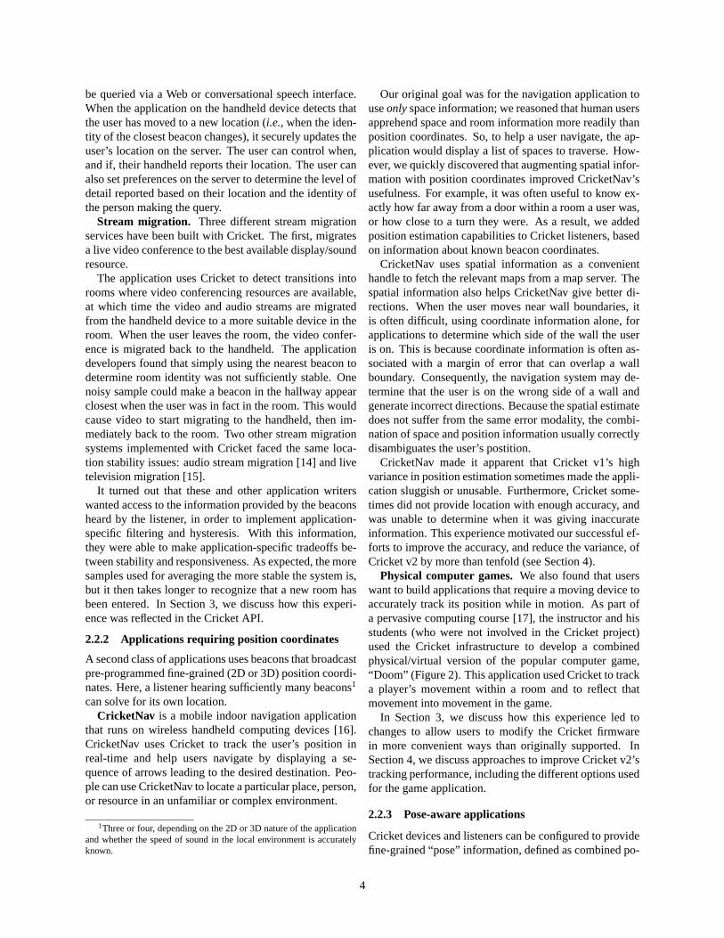
Physical computer games. We also found that userswant to build applications that require a moving device toaccurately track its position while in motion. As part ofa pervasive computing course [17], the instructor and hisstudents (who were not involved in the Cricket project)used the Cricket infrastructure to develop a combinedphysical/virtual version of the popular computer game,“ Doom” (Figure 2). This application used Cricket to tracka player’s movement within a room and to reflect thatmovement into movement in the game.
In Section 3, we discuss how this experience led tochanges to allow users to modify the Cricket firmwarein more convenient ways than originally supported. InSection 4, we discuss approaches to improve Cricket v2’stracking performance, including the different options usedfor the game application.
2.2.3 Pose-aware applications
Cricket devices and listeners can be configured to providefine-grained “ pose” information, defined as combined po-
4
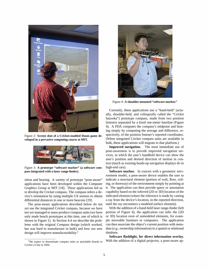
Figure 2: Screen shot of a Cricket-enabled Doom game de-veloped in a pervasive computing course at MIT.
Figure 3: A prototype “software marker” (a software com-pass integrated with a laser range-finder).
sition and bearing. A variety of prototype “ pose-aware”applications have been developed within the ComputerGraphics Group at MIT [18]. These applications led usto develop the Cricket compass. The compass infers a de-vice’s orientation by using multiple US sensors to obtaindifferential distances to one or more beacons [19].
The pose-aware applications described below do notyet use the integrated Cricket compass, because we havenot yet managed to mass-produce compass units (we haveonly made bench prototypes at this time, one of which isshown in Figure 1). In Section 4.4 we describe the prob-lems with the original Compass design (which worked,but was hard to manufacture in bulk) and how our newdesign will improve manufacturability.2
2We expect to disseminate compass units as attachable boards toCricket v2 late in 2004.
Figure 4: A shoulder-mounted “software marker.”
Currently, these applications use a “ hand-held” (actu-ally, shoulder-held, and colloquially called the “ Cricketbazooka” ) prototype compass, made from two positionlisteners separated by a fixed one-meter baseline (Figure4). A PDA computes the compass’s midpoint and bear-ing simply by computing the average and difference, re-spectively, of the position listener’s reported coordinates.(When integrated Cricket compass units are available inbulk, these applications will migrate to that platform.)
Improved navigation. The most immediate use ofpose-awareness is to provide improved navigation ser-vices, in which the user’s handheld device can show theuser’s position and desired direction of motion in con-text (much as existing heads-up navigation displays do inhigh-end cars).
Software marker. In concert with a geometric envi-ronment model, a pose-aware device enables the user toindicate a structural element (portion of wall, fl oor, ceil-ing, or doorway) of the environment simply by pointing atit. The application can then provide query or annotationcapability based on the inferred (2D or 3D) location of theindicated element (where the inference is made by castinga ray from the device’s location, in the reported direction,until the ray encounters a modeled surface element).
With the addition of a hand-held laser range-finder (leftportion of Figure 4), the application can infer the (2Dor 3D) location even of unmodeled elements, for exam-ple moveable furniture or computers. The applicationcan then associate the object’s current position with meta-data (e.g., ownership information) in a spatial or relationaldatabase.
Software flashlight, for direct information overlay.With the addition of a digital projector, a pose-aware ap-
5
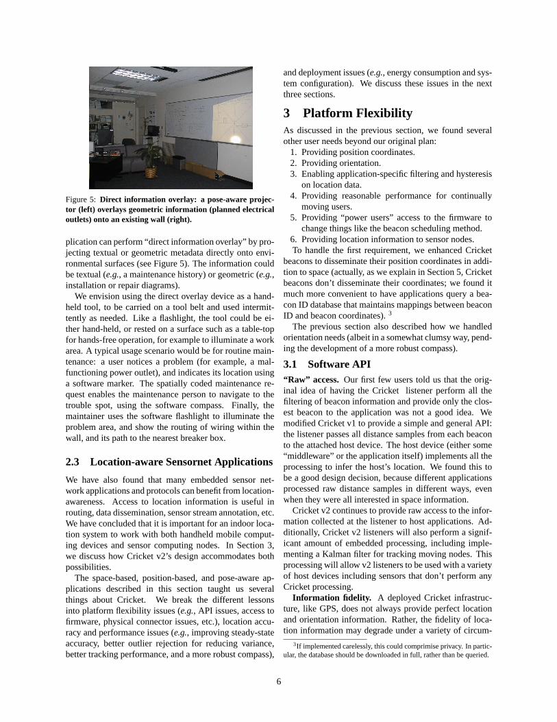
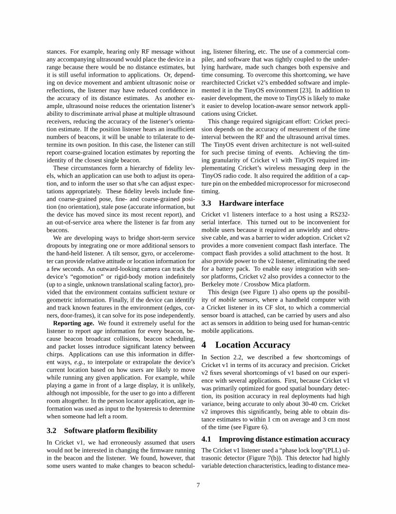
Figure 5: Direct information overlay: a pose-aware projec-tor (left) overlays geometric information (planned electricaloutlets) onto an existing wall (right).
plication can perform “ direct information overlay” by pro-jecting textual or geometric metadata directly onto envi-ronmental surfaces (see Figure 5). The information couldbe textual (e.g., a maintenance history) or geometric (e.g.,installation or repair diagrams).
We envision using the direct overlay device as a hand-held tool, to be carried on a tool belt and used intermit-tently as needed. Like a fl ashlight, the tool could be ei-ther hand-held, or rested on a surface such as a table-topfor hands-free operation, for example to illuminate a workarea. A typical usage scenario would be for routine main-tenance: a user notices a problem (for example, a mal-functioning power outlet), and indicates its location usinga software marker. The spatially coded maintenance re-quest enables the maintenance person to navigate to thetrouble spot, using the software compass. Finally, themaintainer uses the software fl ashlight to illuminate theproblem area, and show the routing of wiring within thewall, and its path to the nearest breaker box.
2.3 Location-aware Sensornet Applications
We have also found that many embedded sensor net-work applications and protocols can benefit from location-awareness. Access to location information is useful inrouting, data dissemination, sensor stream annotation, etc.We have concluded that it is important for an indoor loca-tion system to work with both handheld mobile comput-ing devices and sensor computing nodes. In Section 3,we discuss how Cricket v2’s design accommodates bothpossibilities.
The space-based, position-based, and pose-aware ap-plications described in this section taught us severalthings about Cricket. We break the different lessonsinto platform fl exibility issues (e.g., API issues, access tofirmware, physical connector issues, etc.), location accu-racy and performance issues (e.g., improving steady-stateaccuracy, better outlier rejection for reducing variance,better tracking performance, and a more robust compass),
and deployment issues (e.g., energy consumption and sys-tem configuration). We discuss these issues in the nextthree sections.
3 Platform FlexibilityAs discussed in the previous section, we found severalother user needs beyond our original plan:
1. Providing position coordinates.2. Providing orientation.3. Enabling application-specific filtering and hysteresis
on location data.4. Providing reasonable performance for continually
moving users.5. Providing “ power users” access to the firmware to
change things like the beacon scheduling method.6. Providing location information to sensor nodes.To handle the first requirement, we enhanced Cricket
beacons to disseminate their position coordinates in addi-tion to space (actually, as we explain in Section 5, Cricketbeacons don’t disseminate their coordinates; we found itmuch more convenient to have applications query a bea-con ID database that maintains mappings between beaconID and beacon coordinates). 3
The previous section also described how we handledorientation needs (albeit in a somewhat clumsy way, pend-ing the development of a more robust compass).
3.1 Software API“ Raw” access. Our first few users told us that the orig-inal idea of having the Cricket listener perform all thefiltering of beacon information and provide only the clos-est beacon to the application was not a good idea. Wemodified Cricket v1 to provide a simple and general API:the listener passes all distance samples from each beaconto the attached host device. The host device (either some“ middleware” or the application itself) implements all theprocessing to infer the host’s location. We found this tobe a good design decision, because different applicationsprocessed raw distance samples in different ways, evenwhen they were all interested in space information.
Cricket v2 continues to provide raw access to the infor-mation collected at the listener to host applications. Ad-ditionally, Cricket v2 listeners will also perform a signif-icant amount of embedded processing, including imple-menting a Kalman filter for tracking moving nodes. Thisprocessing will allow v2 listeners to be used with a varietyof host devices including sensors that don’t perform anyCricket processing.
Information fidelity. A deployed Cricket infrastruc-ture, like GPS, does not always provide perfect locationand orientation information. Rather, the fidelity of loca-tion information may degrade under a variety of circum-
3If implemented carelessly, this could comprimise privacy. In partic-ular, the database should be downloaded in full, rather than be queried.
6
stances. For example, hearing only RF message withoutany accompanying ultrasound would place the device in arange because there would be no distance estimates, butit is still useful information to applications. Or, depend-ing on device movement and ambient ultrasonic noise orrefl ections, the listener may have reduced confidence inthe accuracy of its distance estimates. As another ex-ample, ultrasound noise reduces the orientation listener’sability to discriminate arrival phase at multiple ultrasoundreceivers, reducing the accuracy of the listener’s orienta-tion estimate. If the position listener hears an insufficientnumbers of beacons, it will be unable to trilaterate to de-termine its own position. In this case, the listener can stillreport coarse-grained location estimates by reporting theidentity of the closest single beacon.
These circumstances form a hierarchy of fidelity lev-els, which an application can use both to adjust its opera-tion, and to inform the user so that s/he can adjust expec-tations appropriately. These fidelity levels include fine-and coarse-grained pose, fine- and coarse-grained posi-tion (no orientation), stale pose (accurate information, butthe device has moved since its most recent report), andan out-of-service area where the listener is far from anybeacons.
We are developing ways to bridge short-term servicedropouts by integrating one or more additional sensors tothe hand-held listener. A tilt sensor, gyro, or accelerome-ter can provide relative attitude or location information fora few seconds. An outward-looking camera can track thedevice’s “ egomotion” or rigid-body motion indefinitely(up to a single, unknown translational scaling factor), pro-vided that the environment contains sufficient texture orgeometric information. Finally, if the device can identifyand track known features in the environment (edges, cor-ners, door-frames), it can solve for its pose independently.
Reporting age. We found it extremely useful for thelistener to report age information for every beacon, be-cause beacon broadcast collisions, beacon scheduling,and packet losses introduce significant latency betweenchirps. Applications can use this information in differ-ent ways, e.g., to interpolate or extrapolate the device’scurrent location based on how users are likely to movewhile running any given application. For example, whileplaying a game in front of a large display, it is unlikely,although not impossible, for the user to go into a differentroom altogether. In the person locator application, age in-formation was used as input to the hysteresis to determinewhen someone had left a room.
3.2 Software platform flexibility
In Cricket v1, we had erroneously assumed that userswould not be interested in changing the firmware runningin the beacon and the listener. We found, however, thatsome users wanted to make changes to beacon schedul-
ing, listener filtering, etc. The use of a commercial com-piler, and software that was tightly coupled to the under-lying hardware, made such changes both expensive andtime consuming. To overcome this shortcoming, we haverearchitected Cricket v2’s embedded software and imple-mented it in the TinyOS environment [23]. In addition toeasier development, the move to TinyOS is likely to makeit easier to develop location-aware sensor network appli-cations using Cricket.
This change required signigicant effort: Cricket preci-sion depends on the accuracy of mesurement of the timeinterval between the RF and the ultrasound arrival times.The TinyOS event driven architecture is not well-suitedfor such precise timing of events. Achieving the tim-ing granularity of Cricket v1 with TinyOS required im-plementating Cricket’s wireless messaging deep in theTinyOS radio code. It also required the addition of a cap-ture pin on the embedded microprocessor for microsecondtiming.
3.3 Hardware interfaceCricket v1 listeners interface to a host using a RS232-serial interface. This turned out to be inconvenient formobile users because it required an unwieldy and obtru-sive cable, and was a barrier to wider adoption. Cricket v2provides a more convenient compact fl ash interface. Thecompact fl ash provides a solid attachment to the host. Italso provide power to the v2 listener, eliminating the needfor a battery pack. To enable easy integration with sen-sor platforms, Cricket v2 also provides a connector to theBerkeley mote / Crossbow Mica platform.
This design (see Figure 1) also opens up the possibil-ity of mobile sensors, where a handheld computer witha Cricket listener in its CF slot, to which a commercialsensor board is attached, can be carried by users and alsoact as sensors in addition to being used for human-centricmobile applications.
4 Location AccuracyIn Section 2.2, we described a few shortcomings ofCricket v1 in terms of its accuracy and precision. Cricketv2 fixes several shortcomings of v1 based on our experi-ence with several applications. First, because Cricket v1was primarily optimized for good spatial boundary detec-tion, its position accuracy in real deployments had highvariance, being accurate to only about 30-40 cm. Cricketv2 improves this significantly, being able to obtain dis-tance estimates to within 1 cm on average and 3 cm mostof the time (see Figure 6).
4.1 Improving distance estimation accuracyThe Cricket v1 listener used a “ phase lock loop” (PLL) ul-trasonic detector (Figure 7(b)). This detector had highlyvariable detection characteristics, leading to distance mea-
7

-10 0 10 20
Error from true distance (cm)
0.0
0.2
0.4
0.6
0.8
1.0C
umul
ativ
e fr
acti
on o
f m
easu
rem
ents
v1 facingv2 facingv1 30 degree anglev2 30 degree angle
Figure 6: CDFs of measured distances in Cricket v1 andCricket v2, showing v2’s much-improved accuracy.
US Sensor
Amp Phase Lock
Loop
US Detect
3V
(b)
US Tx
(a)
Figure 7: Cricket v1 US circuitry: (a) beacon and (b) listener.
surement errors as high as 30 cm. In Cricket v2 we re-placed the PLL-based detector with a simpler amplitudedetector (Figure 8(b)). This improved the detection ac-curacy substantially, to about 1 cm, but also reduced thesensitivity of the detector circuit. To compensate for this,we increased the ultrasonic transmitter signal strength byincreasing the drive voltage from 3V to 12V (see Fig-ures 7(a) and 8(a)).
The CC1000 radio chip used on the Cricket v2 also pre-sented difficulties because the binary data does not arrivedeterministically (the data does not arrive eight bits at atime). The offset of bits arriving late for a given start sym-bol (representing the start of ultrasound) can change theprecision of Cricket by 7 cm. We compensated for this byrecording the bit offset of the first byte of the start symbolwithin the byte captured by the radio and then adjustingthe timing in the listener firmware.
4.2 Rejecting outliers
We found that precise distance measurements require sen-sitive US sensors, but such sensors react to ambient ul-trasonic noise and high-energy sound pulses. In particu-lar, we found that malfunctioning fl uorescent lights, peo-ple jangling keys, and loud noises (e.g., slamming doors)cause the listener to record bad distance samples. Accu-rate distance estimation therefore requires good outlier re-jection methods.
Initially, we used Cricket to determine the location ofmostly static objects for resource discovery applications(we assumed a person to be static for several seconds be-fore computing the current location). The MinMode al-
3V
US Tx
(a)
Voltage
Multiplier
+6V
-6V
US Sensor
Amp US Detect
(b)
Variable Gain
Figure 8: Cricket v2 US circuitry: (a) beacon and (b) listener.
gorithm implemented in Cricket v1 has good outlier re-jection properties when the listener is static. It first col-lects distance samples for a fixed time window of 5 sec-onds, then it rounds of the samples to the nearest 20 cm.Next, it selects the value that has the maximum numberof occurences as the true distance; if there are several val-ues with the maximum occurence, it selects the minimumvalue as the true distance. Although this algorithm per-forms well when the listener is static, its performance de-grades when the listener is mobile because the dynamicdistance values prevent the algorithm from obtaining thecorrect value with a high enough frequency.
In Cricket v2, the extended Kalman filter (explainedin the next section) used for obtaining position informa-tion while a device is moving maintains an estimate of thevariance of the filter’s position state. We use this to re-ject outliers; the variance of the position estimate definesa threshold, and if a sample falls outside of that threshold,the listener rejects it. This approach usually rejects all re-fl ections and noise, unless the state estimate is itself bad.In that case, as explained below, the Kalman filter’s stateresets, and the “ outlying” sample is not rejected.
4.3 Fast tracking of moving objectsThe applications described in Section 2.2.2 require fastupdates of a moving object’s position coordinates. Be-cause Cricket is an active beacon architecture, meetingthis requirement is more involved than if it were an activemobile system like the Active Bat. The reason for this isthat the simultaneity condition— the availability of mul-tiple distance estimates to known position beacon/sensorpositions in the infrastructure for the same current posi-tion of the moving device—is not satisfied in general.
4.3.1 The “ Doom” approach
The initial attempts by the developers of the Cricket-enabled Doom to use multiple Cricket v1 beacons on theceiling and the full 3D location tracking code did not givea fast enough update rate for game play. New values fromat least three beacons were required to calculate each lo-cation. The 3D solver did not always give valid results,causing position calculations to be dropped, further re-ducing the update rate. Also, setting up the game requiredconfiguring the position of each of the beacons.
They addressed both issues by simplifying the prob-lem, taking advantage of the way user’s would move whileplaying the game. First, they used only two beacons, one
8
on each side of the projection screen showing the vir-tual world, at waist height (blackboard chalk rails whereconvenient holders). The beacon’s code was modified totransmit more frequently, as they where only competingwith each other for transmission time. The moving de-vice’s location was calculated only in a 2D horizontalplane using the intersection of the two circles centered ateach beacon. There is only one valid solution, the sec-ond intersection point is always behind the display. Here,responsiveness is more important than absolute accuracy.
The developers of this application also came up with asimple and elegant application-specific beacon configura-tion method to avoid manual configuration. At initializa-tion, a listener is held very close to one of the two bea-cons, and measures the distance to the other beacon. Theresult gives the distance between the two beacons, whichis the only parameter needed to configure the system. (InSection 5.2 we show how a more general method solves amore general configuration problem.)
Another way to use Cricket for this application wouldbe to make the moving device an active transmitter. Thegame developers attempted this method, but given thetime constraints of a term project and the added complex-ity of merging two streams of location updates, they werenot able to get the information gathered at two differentlisteners coordinated at a single location.
This experience, as well as our own experience withCricketNav, suggested a number of improvement possi-bilities. The rest of this section discusses some of them.
4.3.2 Using an extended Kalman filter
A Cricket v1 listener computes its position by storingthe last T seconds of distinct beacon samples and run-ning a least-squares minimization (LSQ) to minimize theresidual error. Specifically, if the known beacon posi-tion of beacon i is bi and a distance estimate from itis di, the listener estimates its position p by minimizing∑
N
i=1(‖bi − p‖ − di)
2, where ‖bi − p‖ is the Euclideandistance between the coordinates bi and p.4
Of course, if the device is in motion, a large value of T
leads to inaccuracies because LSQ will use old distancesthat may not be close to the current position. Moreover,in general, LSQ alone does not adequately capture motionstate. GPS faces a similar problem, and handles it using aKalman filter [5]. Cricket v2 also implements a Kalmanfilter to help a moving device track its position.
Like GPS, Cricket v2’s Kalman filter maintains a statevector that estimates the device’s current position and ve-locity (currently, we don’t use higher order terms like ac-celeration). Unlike GPS, Cricket v2’s filter has to oper-
4LSQ posed in this manner is computationally very intensive, so thelistener linearlizes these equations and approximates the solution. Thatapproximation does not always minimize the true least-squared error, butis usually good enough.
ate “ single-constraint-at-a-time” , because the simultane-ity condition does not hold. The idea in the Kalman filteris simple: maintain the device’s position and velocity esti-mates, and assume that between beacon chirps, the devicemoves at constant velocity. Each beacon chirp defines atime-step. The filter uses a predictor to produce an esti-mate of the device’s position at any time between chirps,and a corrector to rectify the position and velocity statewhenever a beacon chirp is heard and the reported dis-tance deviates from what the predictor suggests.
A covariance matrix refl ects the filter’s confidence inthe state vector. With each incoming measurement we up-date our state vector based on the new data, weighing thestate against the new information by comparing the cur-rent covariance against the variance of the new measure-ment.
Once in a while, the Kalman filter’s state becomes bad(the covariance matrix has large values), suggesting thatits predictions are wrong. After substantial experimenta-tion, we found that a good way to reset the bad state ofthe Kalman filter is to obtain a new fix (a more accurateposition estimate) on the device’s position using LSQ onthe past small number of beacon samples, ignoring theKalman filter.
We found that one way to obtain a good fix is to movefrom a purely active beacon system to a hybrid systemwhere a moving listener would become an active trans-mitter whenever the Kalman filter’s state went bad. Todo this, while maintaining Cricket’s scaling and privacygoals, requires a new protocol. Cricket v2 uses the fol-lowing method:
1. In the common case, the listener does not transmitany information, only beacons do.
2. If the listener’s Kalman filter state is bad (covari-ances above a configurable threshold), then it be-comes an active transmitter. This usually happens ifthe device experiences sudden linear acceleration orturn. It generates concurrent RF and US pulse, withthe RF message having no information in it otherthan a randomly generated nonce. This message issent in a specific timeslot when all the beacons listenon the channel.
3. If a beacon hears an RF message and the correspond-ing US pulse in the “ beacon listening” timeslot, itwaits for a short period of time and broadcasts thenonce (set by the listener) together with the distanceestimate. The listener hears this information fromall the beacons, obtaining good information about itscurrent position because the simultaneity conditionnow holds.
It is important to note that the transition to an activetransmission from the moving listener happens only whenthe Kalman filter’s state is bad, which means that the sys-tem as a whole is likely to remain scalable because it is un-
9
0 50 100 1500
0.1
0.2
0.3
0.4
0.5
0.6
0.7
0.8
0.9
1
Error (cm)
Occ
uran
ces
Hybrid−MultiModalActiveBeacon−MultiModalActiveBeacon−LSQ
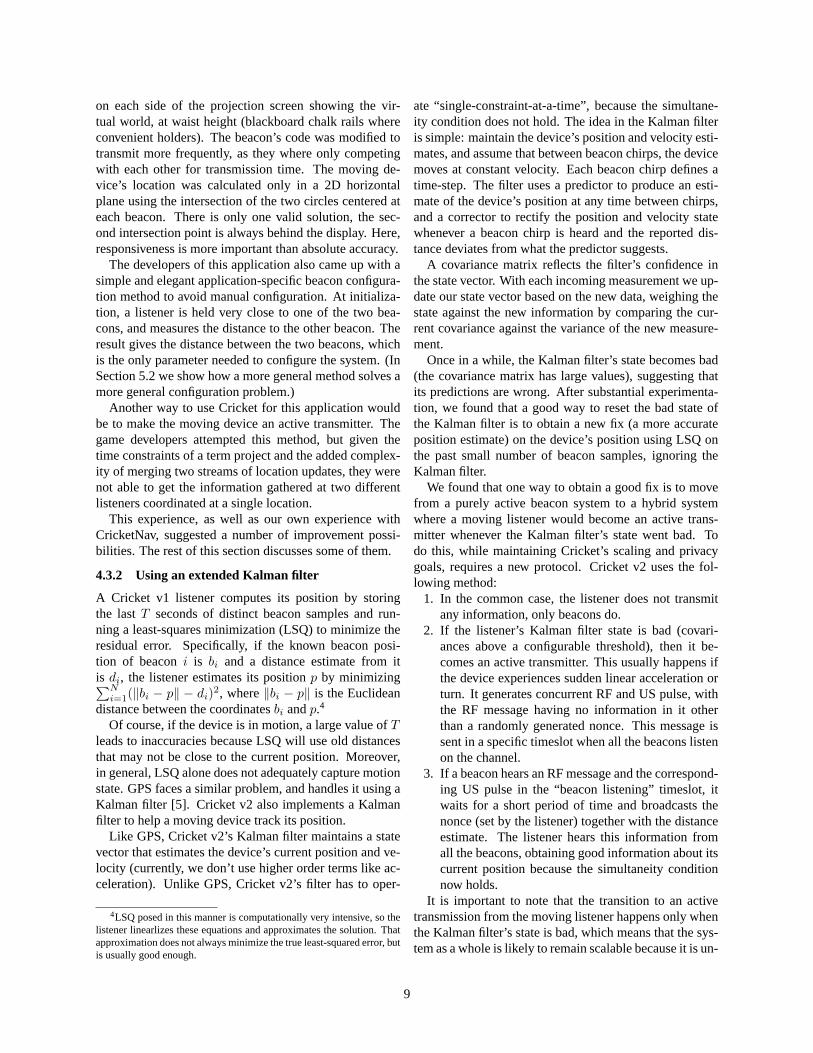
Figure 9: CDF of tracking accuracy at a speed of about0.7 m/s for three Cricket schemes; the best scheme is amulti-modal Kalman filter (not described in this paper) thatuses the hybrid approach of occasionally going into active-transmit mode. The median error is comparable to an al-ways actively transmitting mobile scheme.
likely for every listener in a room to simultaneously havea bad filter state. The use of a random nonce does not di-rectly reveal the mobile’s identity, and the beacons broad-casting the distance estimates back to the listener solvesthe problem of correlating these samples.
4.3.3 Conducting experiments
We found it difficult to design a testbed facilitating re-peatable experiments. The characteristics of RF and ultra-sound depend on ambient conditions, walls, people in thevicinity of the transmissions, etc. All our distance estima-tion experiments were conducted in a variety of differentrooms, lab space, and corridors.
Motion tracking proved particularly problematic, be-cause we wanted to compare the performance of differentmethods under identical conditions. To do this, we boughta computer-controlled Lego train set and tens of meters oftrain tracks, and set it up in a large room. We attacheda Cricket listener to the train and beacons to the ceiling.We wrote utilities to precisely control the movement pat-tern and speed of the train, including pause times and ran-dom velocities between pauses. We experimented withthis apparatus at speeds of up to about 1 m/s. This exper-imental setup included a number of real-world effects, in-cluding multiple beacons (up to six) interacting with oneanother, varying distances from the different beacons tothe listener, and ultrasonic noise and refl ections (in fact,we found that the engine of the train generated some ul-trasonic noise that the listener had to filter out!).
Figure 9 shows a sample CDF of the tracking accuracyat an average movement speed of 0.7 m/s. The medianinaccuracy for the best scheme (the hybrid scheme) is un-der 20cm, and the lag is one-sided, which means that anapplication may be able to account for it. Overall, we are
R 1
R 2 R
3
d 1
d 2
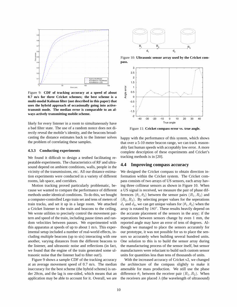
Figure 10: Ultrasonic sensor array used by the Cricket com-pass.
-2
-1.5
-1
-0.5
0
0.5
1
1.5
2
2.5
3
-40 -30 -20 -10 0 10 20 30 40
Angle
err
or
True angle
Figure 11: Cricket compass error vs. true angle.
happy with the performance of this system, which showsthat over a 5-10 meter beacon range, we can track reason-ably fast human speeds with acceptably low error. A morecomplete description of these experiments and Cricket’stracking methods is in [20].
4.4 Improving compass accuracy
We designed the Cricket compass to obtain direction in-formation within the Cricket system. The Cricket com-pass consists of two arrays of US sensors, each array hav-ing three collinear sensors as shown in Figure 10. Whena US signal is received, we measure the pair of phase dif-ferences (θ1, θ2) between the sensor pairs (R1, R2) and(R2, R3). By selecting proper values for the seperationsd1 and d2, we can get unique values for (θ1, θ2) when thearray is rotated by 180◦. These results heavily depend onthe accurate placement of the sensors in the aray; if theseperations between sensors change by even 1 mm, thereported angle may have an error of tens of degrees. Al-though we managed to place the sensors accurately forour prototype, it was not possible for us to place the sen-sors so accurately when building several hundred units.One solution to this is to build the sensor array duringthe manufacturing process of the sensor itself, but sensormanufacturers were reluctant to build such custom sensorunits for quantities less than tens of thousands of units.
With the increased accuracy of Cricket v2, we changedthe architecture of the compass slightly to make itamenable for mass production. We still use the phasedifference θ1 between the receiver pair (R1, R2). Whenthe receivers are placed λ (the wavelength of ultrasound)
10
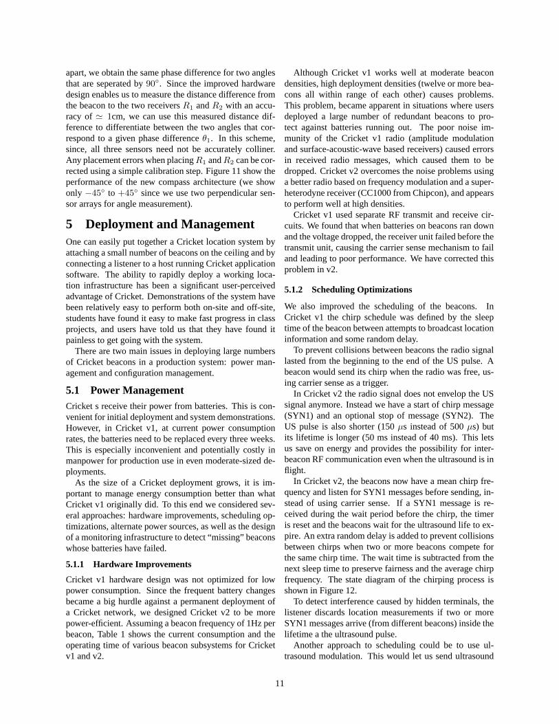
apart, we obtain the same phase difference for two anglesthat are seperated by 90◦. Since the improved hardwaredesign enables us to measure the distance difference fromthe beacon to the two receivers R1 and R2 with an accu-racy of ' 1cm, we can use this measured distance dif-ference to differentiate between the two angles that cor-respond to a given phase difference θ1. In this scheme,since, all three sensors need not be accurately colliner.Any placement errors when placing R1 and R2 can be cor-rected using a simple calibration step. Figure 11 show theperformance of the new compass architecture (we showonly −45◦ to +45◦ since we use two perpendicular sen-sor arrays for angle measurement).
5 Deployment and ManagementOne can easily put together a Cricket location system byattaching a small number of beacons on the ceiling and byconnecting a listener to a host running Cricket applicationsoftware. The ability to rapidly deploy a working loca-tion infrastructure has been a significant user-perceivedadvantage of Cricket. Demonstrations of the system havebeen relatively easy to perform both on-site and off-site,students have found it easy to make fast progress in classprojects, and users have told us that they have found itpainless to get going with the system.
There are two main issues in deploying large numbersof Cricket beacons in a production system: power man-agement and configuration management.
5.1 Power ManagementCricket s receive their power from batteries. This is con-venient for initial deployment and system demonstrations.However, in Cricket v1, at current power consumptionrates, the batteries need to be replaced every three weeks.This is especially inconvenient and potentially costly inmanpower for production use in even moderate-sized de-ployments.
As the size of a Cricket deployment grows, it is im-portant to manage energy consumption better than whatCricket v1 originally did. To this end we considered sev-eral approaches: hardware improvements, scheduling op-timizations, alternate power sources, as well as the designof a monitoring infrastructure to detect “ missing” beaconswhose batteries have failed.
5.1.1 Hardware Improvements
Cricket v1 hardware design was not optimized for lowpower consumption. Since the frequent battery changesbecame a big hurdle against a permanent deployment ofa Cricket network, we designed Cricket v2 to be morepower-efficient. Assuming a beacon frequency of 1Hz perbeacon, Table 1 shows the current consumption and theoperating time of various beacon subsystems for Cricketv1 and v2.
Although Cricket v1 works well at moderate beacondensities, high deployment densities (twelve or more bea-cons all within range of each other) causes problems.This problem, became apparent in situations where usersdeployed a large number of redundant beacons to pro-tect against batteries running out. The poor noise im-munity of the Cricket v1 radio (amplitude modulationand surface-acoustic-wave based receivers) caused errorsin received radio messages, which caused them to bedropped. Cricket v2 overcomes the noise problems usinga better radio based on frequency modulation and a super-heterodyne receiver (CC1000 from Chipcon), and appearsto perform well at high densities.
Cricket v1 used separate RF transmit and receive cir-cuits. We found that when batteries on beacons ran downand the voltage dropped, the receiver unit failed before thetransmit unit, causing the carrier sense mechanism to failand leading to poor performance. We have corrected thisproblem in v2.
5.1.2 Scheduling Optimizations
We also improved the scheduling of the beacons. InCricket v1 the chirp schedule was defined by the sleeptime of the beacon between attempts to broadcast locationinformation and some random delay.
To prevent collisions between beacons the radio signallasted from the beginning to the end of the US pulse. Abeacon would send its chirp when the radio was free, us-ing carrier sense as a trigger.
In Cricket v2 the radio signal does not envelop the USsignal anymore. Instead we have a start of chirp message(SYN1) and an optional stop of message (SYN2). TheUS pulse is also shorter (150 µs instead of 500 µs) butits lifetime is longer (50 ms instead of 40 ms). This letsus save on energy and provides the possibility for inter-beacon RF communication even when the ultrasound is infl ight.
In Cricket v2, the beacons now have a mean chirp fre-quency and listen for SYN1 messages before sending, in-stead of using carrier sense. If a SYN1 message is re-ceived during the wait period before the chirp, the timeris reset and the beacons wait for the ultrasound life to ex-pire. An extra random delay is added to prevent collisionsbetween chirps when two or more beacons compete forthe same chirp time. The wait time is subtracted from thenext sleep time to preserve fairness and the average chirpfrequency. The state diagram of the chirping process isshown in Figure 12.
To detect interference caused by hidden terminals, thelistener discards location measurements if two or moreSYN1 messages arrive (from different beacons) inside thelifetime a the ultrasound pulse.
Another approach to scheduling could be to use ul-trasound modulation. This would let us send ultrasound
11
Sub system Processor RF Tranmitter RF Receiver US Transmitter
Cricket v1 (active) 3.7mA×50ms 1.5mA×50ms 6mA×1ms 2mA×250µsCricket v1 (idle) 1.5mA×1000ms 1.7µA×1000ms 0.7mA×1000ms 1.5mA×1000ms
(idle)Cricket v2 (active) 7mA×45ms 7mA×5.3ms 7.4mA×32ms 50mA×120µsCricket v2 (idle) 10µA×1000ms 0.1µA×1000 - 0.5µA×1000ms
Table 1: Power consumption of Cricket v1 and v2 beacon subsystems.
Receive(30ms + ∆ 1−3ms)
Idle state(800−1200ms)
Send
If failed
*
* The receive state is reset each time a beacon is heard
Figure 12: State diagram of the beaconing process.
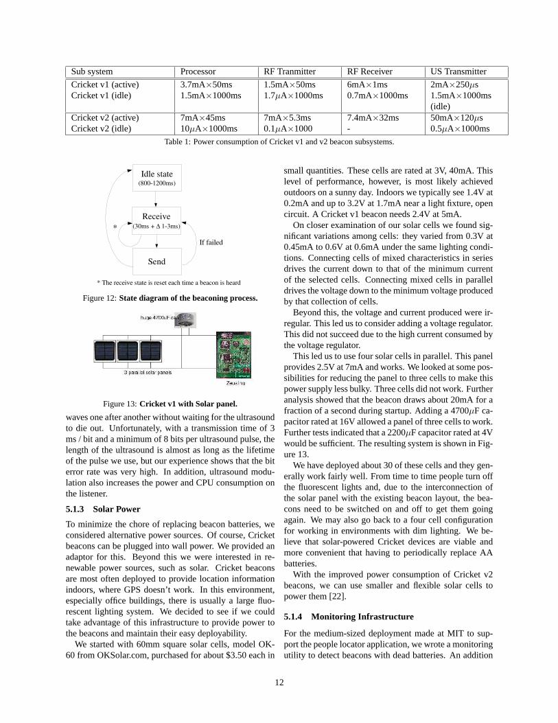
Figure 13: Cricket v1 with Solar panel.
waves one after another without waiting for the ultrasoundto die out. Unfortunately, with a transmission time of 3ms / bit and a minimum of 8 bits per ultrasound pulse, thelength of the ultrasound is almost as long as the lifetimeof the pulse we use, but our experience shows that the biterror rate was very high. In addition, ultrasound modu-lation also increases the power and CPU consumption onthe listener.
5.1.3 Solar Power
To minimize the chore of replacing beacon batteries, weconsidered alternative power sources. Of course, Cricketbeacons can be plugged into wall power. We provided anadaptor for this. Beyond this we were interested in re-newable power sources, such as solar. Cricket beaconsare most often deployed to provide location informationindoors, where GPS doesn’t work. In this environment,especially office buildings, there is usually a large fl uo-rescent lighting system. We decided to see if we couldtake advantage of this infrastructure to provide power tothe beacons and maintain their easy deployability.
We started with 60mm square solar cells, model OK-60 from OKSolar.com, purchased for about $3.50 each in
small quantities. These cells are rated at 3V, 40mA. Thislevel of performance, however, is most likely achievedoutdoors on a sunny day. Indoors we typically see 1.4V at0.2mA and up to 3.2V at 1.7mA near a light fixture, opencircuit. A Cricket v1 beacon needs 2.4V at 5mA.
On closer examination of our solar cells we found sig-nificant variations among cells: they varied from 0.3V at0.45mA to 0.6V at 0.6mA under the same lighting condi-tions. Connecting cells of mixed characteristics in seriesdrives the current down to that of the minimum currentof the selected cells. Connecting mixed cells in paralleldrives the voltage down to the minimum voltage producedby that collection of cells.
Beyond this, the voltage and current produced were ir-regular. This led us to consider adding a voltage regulator.This did not succeed due to the high current consumed bythe voltage regulator.
This led us to use four solar cells in parallel. This panelprovides 2.5V at 7mA and works. We looked at some pos-sibilities for reducing the panel to three cells to make thispower supply less bulky. Three cells did not work. Furtheranalysis showed that the beacon draws about 20mA for afraction of a second during startup. Adding a 4700µF ca-pacitor rated at 16V allowed a panel of three cells to work.Further tests indicated that a 2200µF capacitor rated at 4Vwould be sufficient. The resulting system is shown in Fig-ure 13.
We have deployed about 30 of these cells and they gen-erally work fairly well. From time to time people turn offthe fl uorescent lights and, due to the interconnection ofthe solar panel with the existing beacon layout, the bea-cons need to be switched on and off to get them goingagain. We may also go back to a four cell configurationfor working in environments with dim lighting. We be-lieve that solar-powered Cricket devices are viable andmore convenient that having to periodically replace AAbatteries.
With the improved power consumption of Cricket v2beacons, we can use smaller and fl exible solar cells topower them [22].
5.1.4 Monitoring Infrastructure
For the medium-sized deployment made at MIT to sup-port the people locator application, we wrote a monitoringutility to detect beacons with dead batteries. An addition
12
to the locator software running on each handheld recordedthe set of beacons heard in a time window (e.g., 5 minutes)then reported the beacon names to a server. The serverrecorded the time at which each beacon was last reported.Beacons not heard from for a long period of time whereeither dead, or no listener had been near that beacon. Thelatter could be checked by taking a listener to close to thebeacon. We used the same infrustructure to measure bat-tery life times for beacons by leaving a listener sitting nearthe beacon until the beacon’s battery died.
5.2 Configuration ManagementOriginally, we had envisioned that each beacon wouldsend its space and coordinate information on the RF chan-nel. Over time, we found that it was simpler in many casesfor a beacon to only send a unique ID, and for the map-ping between the ID and the space/coordinate informationto be maintained in a central database. In this approach,the listener or host device downloads the database for eachbuilding of interest.
5.3 Assisted Coordinate ConfigurationConfiguring spatial information in the beaon had beeneasy, but configuring accurate beacon coordinates hasbeen a major bottleneck in deploying Crickets. It ispainful to use measuring tape to obtain beacon coordi-nates manually. Over time, we have developed a Bea-conConfig application to automate the beacon configura-tion process and allow rapid and ad hoc deployment of theCricket system in any desired location.
BeaconConfig works by using the Cricket listener tocollect distance measurements from all the beacons thatneeds to be configured. The user picks three beacons asreferences and places the listener underneath each of themto collect distance samples. The references are used todefine the origin and the orientation of the coordinate sys-tem. After collecting the measurements, the coordinatesof each of the reference beacons are immediately known.The listener can then use the three reference coordinatesand the collected distance measurements to compute thecoordinates for the rest of the beacons.
The BeaconConfig application assumes that all the bea-cons that need to be configured are within the listener’s re-ceiving range. Thus, it is suitable for open-area or single-room deployment.
5.4 Beacon auto-localizationFor a large Cricket deployment, it is inconvenient to con-figure beacon coordinates by manually visiting each ofthem. Ideally, what we need is an “ anchor-free auto local-ization” algorithm, where beacons measure inter-beacondistances to their neighbors and run a distributed algo-rithm to compute a coordinate assignment that satisfiesthe measured distances.
Listener
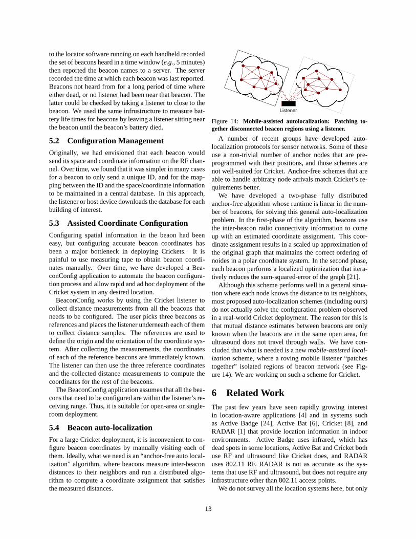
Figure 14: Mobile-assisted autolocalization: Patching to-gether disconnected beacon regions using a listener.
A number of recent groups have developed auto-localization protocols for sensor networks. Some of theseuse a non-trivial number of anchor nodes that are pre-programmed with their positions, and those schemes arenot well-suited for Cricket. Anchor-free schemes that areable to handle arbitrary node arrivals match Cricket’s re-quirements better.
We have developed a two-phase fully distributedanchor-free algorithm whose runtime is linear in the num-ber of beacons, for solving this general auto-localizationproblem. In the first-phase of the algorithm, beacons usethe inter-beacon radio connectivity information to comeup with an estimated coordinate assignment. This coor-dinate assignment results in a scaled up approximation ofthe original graph that maintains the correct ordering ofnoides in a polar coordinate system. In the second phase,each beacon performs a localized optimization that itera-tively reduces the sum-squared-error of the graph [21].
Although this scheme performs well in a general situa-tion where each node knows the distance to its neighbors,most proposed auto-localization schemes (including ours)do not actually solve the configuration problem observedin a real-world Cricket deployment. The reason for this isthat mutual distance estimates between beacons are onlyknown when the beacons are in the same open area, forultrasound does not travel through walls. We have con-cluded that what is needed is a new mobile-assisted local-ization scheme, where a roving mobile listener “ patchestogether” isolated regions of beacon network (see Fig-ure 14). We are working on such a scheme for Cricket.
6 Related WorkThe past few years have seen rapidly growing interestin location-aware applications [4] and in systems suchas Active Badge [24], Active Bat [6], Cricket [8], andRADAR [1] that provide location information in indoorenvironments. Active Badge uses infrared, which hasdead spots in some locations, Active Bat and Cricket bothuse RF and ultrasound like Cricket does, and RADARuses 802.11 RF. RADAR is not as accurate as the sys-tems that use RF and ultrasound, but does not require anyinfrastructure other than 802.11 access points.
We do not survey all the location systems here, but only
13

mention those systems that share some similarities withCricket. The Bristol indoor positioning system has a de-sign similar to Cricket in that it uses active beacons andpassive receivers [9]. The system uses PIC processors,which limits the amount of computation possible on eachnode in the system. This limit forces the beacons to beplaced in a regular pattern on the ceiling, which in turncauses the installation of the beacons to be more difficult.
The Place Lab project uses existing WiFi Access Points(like RADAR) to determine location information for Webapplications. Place Lab hopes to provide a community-driven database of WiFi locations for mobile users. Ap-plications can then compare the signal strength of avail-able access points to the Place Lab database to determinea coarse-grained location [10].
Aetherwire & Location and Ubisense are commercialventures that focus on ultrawideband (UWB) technologyto track objects and people. Ubisense reports an accu-racy of tens of centimeters in an “ active mobile” archi-tecture [2], in which the infrastructure can track users.UWB does not require line-of-sight connectivity, but cur-rent systems are not as accurate as Cricket. We also be-lieve that a number of our techniques to handle erroneousdistances extend to other systems that do not employ ourranging technology.
Researchers have investigated Bayesian and Kalmanfilter methods for tracking users [7, 3]. There is an exten-sive and growing body of work on improving the perfor-mance of GPS using various filtering and statistical tech-niques, some of which might also apply to indoor locationsystems [12].
7 ConclusionIn the process of our own development and experimen-tation with Cricket v1, and in cataloguing the reactionsof numerous users of the device, we learned a numberof useful lessons. First, we learned that the API to thedevice had to be rich enough to support a wide (and un-expected) variety of usages, and that users did not wantall of the underlying mechanism (scheduling, etc.) hid-den from them. Second, we learned that applications re-quire either highly accurate location information, or use-ful fidelity information under degraded conditions, in or-der to adjust their operation appropriately. We used theselessons to make significant improvements to the distanceestimation accuracy, outlier rejection, position accuracy,movement tracking performance, and orientation estima-tion of Cricket v2. Finally, we learned that deploymentand management issues such as configuration and powerconsumption become significant operational issues evenat medium scales, i.e., with the use of just a few tens ofdevices. We also described how, with our increased un-derstanding of user needs, we modified the capabilities ofthe beacons, listeners, and the overall system.
We used this knowledge in the design of Cricket v2.Two different prototype units of v2 are now available, andmass-produced units are scheduled to be commerciallyavailable in the first quarter of 2004. A noteworthy fea-ture of the new listeners is that they can be attached toa device’s CF slot, and can also act as sensor computingnodes with sensors attached to them. Finally, we are alsodesigning a new compass device based on the method de-scribed in this paper, and hope to have those units for dis-semination sometime in 2004.
References[1] P. Bahl and V. Padmanabhan. RADAR: An In-Building
RF-based User Location and Tracking System. In Proc.IEEE INFOCOM, Tel-Aviv, Israel, March 2000.
[2] J. Cadman. Deploying Commercial Location-Aware Sys-tems. In Proc. Fifth International Conference on Ubiqui-tous Computing, October 2003.
[3] D. Fox, J. Hightower, H. Kauz, L. Liao, and D. Pat-terson. Bayesian Techniques for Location Estima-tion. In Proc. Workshop on Location-aware Comput-ing, part of UBICOMP Conf., Seattle, WA, October2003. Available from http:www.ubicomp.org/ubicomp2003/workshops/locationaware/.
[4] IT Roadmap to a Geospatial Future. http://www.nap.edu/html/geospatial_future/, 2003.
[5] I. Getting. The Global Positioning System. IEEE Spec-trum, 30(12):36–47, December 1993.
[6] A. Harter, A. Hopper, P. Steggles, A. Ward, and P. Webster.The Anatomy of a Context-Aware Application. In Proc.5th ACM MOBICOM Conf., Seattle, WA, August 1999.
[7] J. Krumm. Probabilistic Inferencing for Location. InProc. Workshop on Location-aware Computing, part ofUBICOMP Conf., Seattle, WA, October 2003. Availablefrom http:www.ubicomp.org/ubicomp2003/workshops/locationaware/.
[8] N. Priyantha, A. Chakraborty, and H. Balakrishnan. TheCricket Location-Support System. In Proc. 6th ACM MO-BICOM Conf., Boston, MA, August 2000.
[9] C. Randell and H. Muller. Exploring the Dynamic Mea-surement of Position. In Proc. Sixth International Sym-posium on Wearable Computers, pages 117–124, Seattle,WA, October 2002.
[10] B. Schilit, A. LaMarca, D. McDonald, J. Tabert, E. Cadag,G. Borriello, and W. Griswold. Bootstrapping theLocation-enhanced World Wide Web. In Proc. Fifth In-ternational Conference on Ubiquitous Computing, Octo-ber 2003.
[11] M. Spreitzer and M. Theimer. Providing Location Infor-mation in a Ubiquitous Computing Environment. In Proc.14th ACM SIGOPS Conf., pages 270–283, Asheville, NC,December 1993.
[12] G. Strang and K. Borre. Linear Algebra, Geodesy, andGPS. Wellesley Cambridge Press, 1997.
[13] Suppressed. Removed for anonymity.[14] Suppressed. Removed for anonymity.[15] Suppressed. Removed for anonymity.
14

[16] Suppressed. Removed for anonymity.[17] Suppressed. Removed for anonymity.[18] Suppressed. Removed for anonymity.[19] Suppressed. Removed for anonymity.[20] Suppressed. Removed for anonymity.[21] Suppressed. Removed for anonymity.[22] Iowa Thin Film home page. http://www.
iowathinfilm.com/.[23] http://webs.cs.berkeley.edu/tos/.[24] R. Want, A. Hopper, V. Falcao, and J. Gibbons. The Active
Badge Location System. ACM Transactions on Informa-tion Systems, 10(1):91–102, January 1992.
15