Embed Size (px)
Citation preview
ENSEMBLE AMPLIFIER
SPA-150R-L
Owner’s Manual
Thank you for purchasing LESLIE Stationary Speaker / Ensem-ble Amplifier SPA-150R-L.This amplifier is equipped with 4-channel inputs, the reverb ef-fect, 150W output, and three 2-way speakers, for various sound reinforcement purposes.Please read this manual carefully first, for safely using and enjoy-ing music with this unit for many years to come.Keep this manual at hand for later reference.
Table Of ContentsIMPORTANT SAFETY INSTRUCTIONS............... 2NAMES AND FUNCTIONS ................................. 6APPLICATIONS................................................... 8
EXAMPLE FOR HARMONICA SOLO ......................................................8TO INCREASE THE POWER ......................................................................8EXAMPLE: HARMONICA ENSEMBLE ...................................................9EXAMPLE: MELODION ENSEMBLE ....................................................10EXAMPLE: MELODION AND GUITAR DUO......................................11EXAMPLE: ENSEMBLE KEYBOARDS ..................................................12EXAMPLE: SINGLE KEYBOARD ...........................................................13AS STATIONARY-UNITS OF LESLIE SPEAKERS.................................14
SPECIFICATIONS .............................................. 15MAIN FEATURES .............................................. 15BLOCK DIAGRAM, FREQ. RESPONSE .............. 15SERVICE ............................................................ 16
Stationary Speaker
SPA-150R-L Owner’s Manual
2 IMPORTANT SAFETY INSTRUCTIONSRead these instructions.
Keep these instructions.
Heed all warnings.
Follow all instructions.
Do not use this apparatus near water.
Clean only with dry cloth.
Do not block any ventilation openings.Install in accordance with the manufacturer’s instructions.
Do not install near any heat sources such as radiators, heat registers, stoves or other apparatus (including amplifiers) that produce heat.
Do not defeat the safety purpose of the polarized or grounding-type plug. A polarized plug has two blades with one wider than the other. A grounding type plug has two blades and a third grounding prong. The wider blade or third prong is provided for your safety. If the pro-vided plug does not fit into your outlet, consult an electrician for re-placement of the obsolete outlet.
Protect the power cord from being walked on or pinched, particu-larly at plugs, convenience receptacles, and the point where they exit from the apparatus.
Only use attachments/accessories specified by the manufacturer.
Use only with the cart, stand, tripod, bracket, or table specified by the manufacturer, or sold with the apparatus. When cart is used: use cau-tion when moving the cart/apparatus combi-nation to avoid injury from tip-over.
Unplug this apparatus during lightning storms, or when unused for long periods of time.
Refer all servicing to qualified service personnel. Servicing is required when the apparatus has been damaged in any way, such as power-supply cord or plug is damaged, liquid has been spilled or objects have fallen into the apparatus, the apparatus has been exposed to rain or moisture, does not operate normally, or has been dropped.
Apparatus shall not be exposed to dripping or splashing and no ob-jects filled with liquids, such as vases, shall be placed on the appara-tus.
WARNING: To reduce the risk of fire or electric shock, do not expose this apparatus to rain or moisture.
In case in the future your instrument gets too old to play/use or malfunctions beyond repair, please observe the instructions of this mark, or, if any question, be sure to contact your dealer or your nearest town or municipal office for its proper disposal.
3
SPA-150R-L Owner’s Manual
FOR UNITED KINGDOM:FOR YOUR SAFETY, PLEASE READ THE FOLLOWING TEXT CAREFULLYThis appliance is supplied with a molded 3-pin mains plug for your safety and convenience.The plug contains a 5 amp fuse.Should the fuse need to be replaced, please ensure that the replacement fuse has a rating of 5 amps and that it is approved by ASTA or BSI to BSI1362.
Check for the ASTA mark or the BSI mark on the body of the fuse.
If the plug contains a removable fuse cover, you must ensure that it is refitted when the fuse is replaced.If the fuse cover is lost, the plug must not be used until a replacement cover is obtained.A replacement fuse cover can be obtained from your local Hammond Dealer.
IF THE FITTED MOULDED PLUG IS UNSUITABLE FOR THE SOCKET OUTLET IN YOUR HOME, THEN THE FUSE SHOULD BE REMOVED AND THE PLUG CUT OFF AND DISPOSED OF SAFELY.THERE IS A DANGER OF SEVERE ELECTRICAL SHOCK IF THE CUT-OFF PLUG IS INSERTED INTO ANY 13 AMP SOCKET.
If a new plug is to be attached to the cord, please observe the wiring code as shown below.If in any doubt, please consult a qualified electrician.IMPORTANT - The wires in this mains lead are coloured in accordance with the following code: Blue: Neutral Brown: Live
As the colours of the wires in the mains lead of this unit may not correspond with the coloured marking identifying the terminals in your plug, proceed as follows.
The wire which is coloured BLUE must be connected to the terminal in the plug which is marked with the letter N or coloured BLACK.
The wire which is coloured BROWN must be connected to the terminal in the plug which is marked with the letter L or coloured RED.
Under no circumstances should either of these wires be connected to the earth terminal of the
three-pin plug, marked with the letter E or the Earth Symbol .
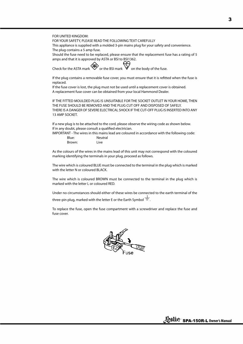
To replace the fuse, open the fuse compartment with a screwdriver and replace the fuse and fuse cover.
SPA-150R-L Owner’s Manual
4
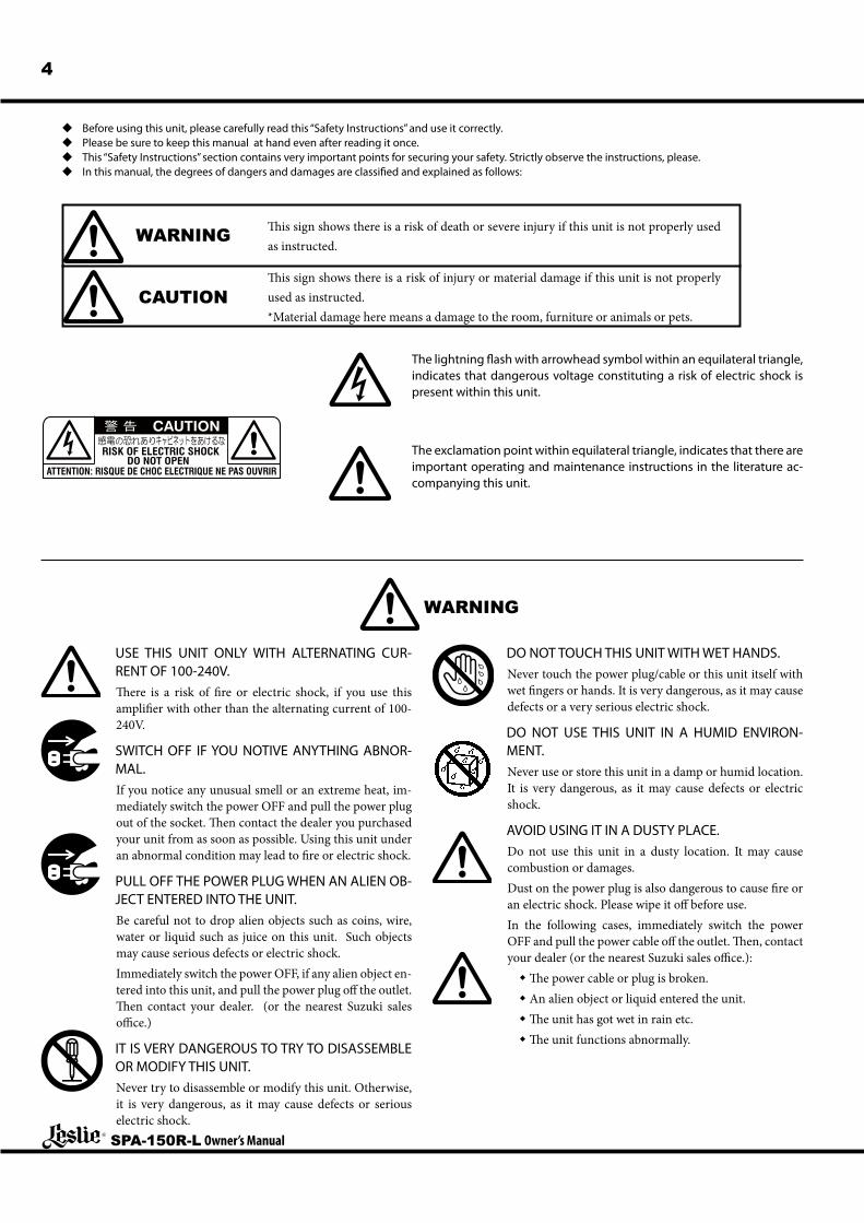
u Before using this unit, please carefully read this “Safety Instructions” and use it correctly.u Please be sure to keep this manual at hand even after reading it once.u This “Safety Instructions” section contains very important points for securing your safety. Strictly observe the instructions, please.u In this manual, the degrees of dangers and damages are classified and explained as follows:
WARNING
CAUTION
This sign shows there is a risk of death or severe injury if this unit is not properly used as instructed.
This sign shows there is a risk of injury or material damage if this unit is not properly used as instructed.*Material damage here means a damage to the room, furniture or animals or pets.
USE THIS UNIT ONLY WITH ALTERNATING CUR-RENT OF 100-240V.There is a risk of fire or electric shock, if you use this amplifier with other than the alternating current of 100-240V.
SWITCH OFF IF YOU NOTIVE ANYTHING ABNOR-MAL.If you notice any unusual smell or an extreme heat, im-mediately switch the power OFF and pull the power plug out of the socket. Then contact the dealer you purchased your unit from as soon as possible. Using this unit under an abnormal condition may lead to fire or electric shock.
PULL OFF THE POWER PLUG WHEN AN ALIEN OB-JECT ENTERED INTO THE UNIT.Be careful not to drop alien objects such as coins, wire, water or liquid such as juice on this unit. Such objects may cause serious defects or electric shock.Immediately switch the power OFF, if any alien object en-tered into this unit, and pull the power plug off the outlet. Then contact your dealer. (or the nearest Suzuki sales office.)
IT IS VERY DANGEROUS TO TRY TO DISASSEMBLE OR MODIFY THIS UNIT.Never try to disassemble or modify this unit. Otherwise, it is very dangerous, as it may cause defects or serious electric shock.
DO NOT TOUCH THIS UNIT WITH WET HANDS.Never touch the power plug/cable or this unit itself with wet fingers or hands. It is very dangerous, as it may cause defects or a very serious electric shock.
DO NOT USE THIS UNIT IN A HUMID ENVIRON-MENT.Never use or store this unit in a damp or humid location. It is very dangerous, as it may cause defects or electric shock.
AVOID USING IT IN A DUSTY PLACE.Do not use this unit in a dusty location. It may cause combustion or damages.Dust on the power plug is also dangerous to cause fire or an electric shock. Please wipe it off before use.In the following cases, immediately switch the power OFF and pull the power cable off the outlet. Then, contact your dealer (or the nearest Suzuki sales office.):w The power cable or plug is broken.w An alien object or liquid entered the unit.w The unit has got wet in rain etc.w The unit functions abnormally.
The lightning flash with arrowhead symbol within an equilateral triangle, indicates that dangerous voltage constituting a risk of electric shock is present within this unit.
The exclamation point within equilateral triangle, indicates that there are important operating and maintenance instructions in the literature ac-companying this unit.
WARNING
5
SPA-150R-L Owner’s Manual
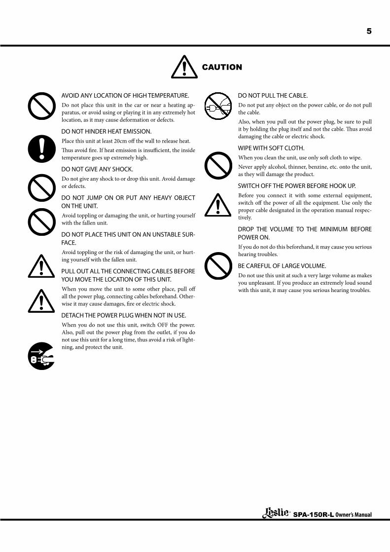
AVOID ANY LOCATION OF HIGH TEMPERATURE.Do not place this unit in the car or near a heating ap-paratus, or avoid using or playing it in any extremely hot location, as it may cause deformation or defects.
DO NOT HINDER HEAT EMISSION.Place this unit at least 20cm off the wall to release heat.Thus avoid fire. If heat emission is insufficient, the inside temperature goes up extremely high.
DO NOT GIVE ANY SHOCK.Do not give any shock to or drop this unit. Avoid damage or defects.
DO NOT JUMP ON OR PUT ANY HEAVY OBJECT ON THE UNIT.Avoid toppling or damaging the unit, or hurting yourself with the fallen unit.
DO NOT PLACE THIS UNIT ON AN UNSTABLE SUR-FACE.Avoid toppling or the risk of damaging the unit, or hurt-ing yourself with the fallen unit.
PULL OUT ALL THE CONNECTING CABLES BEFORE YOU MOVE THE LOCATION OF THIS UNIT.When you move the unit to some other place, pull off all the power plug, connecting cables beforehand. Other-wise it may cause damages, fire or electric shock.
DETACH THE POWER PLUG WHEN NOT IN USE.When you do not use this unit, switch OFF the power. Also, pull out the power plug from the outlet, if you do not use this unit for a long time, thus avoid a risk of light-ning, and protect the unit.
DO NOT PULL THE CABLE.Do not put any object on the power cable, or do not pull the cable.Also, when you pull out the power plug, be sure to pull it by holding the plug itself and not the cable. Thus avoid damaging the cable or electric shock.
WIPE WITH SOFT CLOTH.When you clean the unit, use only soft cloth to wipe.Never apply alcohol, thinner, benzine, etc. onto the unit, as they will damage the product.
SWITCH OFF THE POWER BEFORE HOOK UP.Before you connect it with some external equipment, switch off the power of all the equipment. Use only the proper cable designated in the operation manual respec-tively.
DROP THE VOLUME TO THE MINIMUM BEFORE POWER ON.If you do not do this beforehand, it may cause you serious hearing troubles.
BE CAREFUL OF LARGE VOLUME.Do not use this unit at such a very large volume as makes you unpleasant. If you produce an extremely loud sound with this unit, it may cause you serious hearing troubles.
CAUTION
SPA-150R-L Owner’s Manual
6 NAMES AND FUNCTIONS
TONE1-2
BASS TREBLE
REV.
VOLUME 1
INPUT 1 INPUT 2 INPUT 3
VOLUME 2
TONE3-4
VOLUME 3 VOLUME 4
INPUT 4 LINEOUT
MASTER VOLUME
POWER
AC IN ON
OFF
ONOFF
BASS TREBLE REVERB
1
2
3 4 5 6 7
8 9 10 11 12
13 14 15 16
17 18
19
20
Under 1.3m (4’ 3”)
7
SPA-150R-L Owner’s Manual
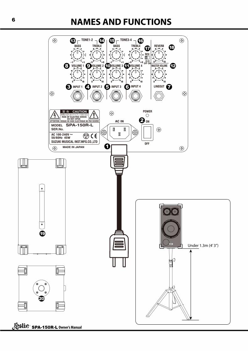
POWER CABLEThis unit is powered by electricity. Before you start using it, plug the power cable into the AC IN jack and the power plug into the AC outlet securely. After using it, pull the cable off the outlet by holding the power plug.
POWER SWITCHThis is the switch to turn [ON/OFF] this unit. While the power is ON, the power indicator lights on.Make sure the power is OFF before you connect any external equipment to this unit, and prevent noise.Set the Master Volume knob (12) at minimum before you switch the power ON, thus a sudden loud sound is avoided.This unit is designed not to produce sound for the first ap-prox. 3 seconds after switched on, for protection of the inter-nal circuits.
to INPUT 1 - 4 JACKThese are voice input terminals. You can connect such exter-nal equipment as mics, Melodions, keyboards, a CD player, etc. from the level of mic to line. The terminals are monaural 1/4˝ phone jacks.
LINE OUT JACKThis is an output terminal for connecting to a recorder or an-other amplifier for obtaining more volume. The output is line level, and the terminal is a monaural 1/4˝ phone jack.
to VOLUME KNOBS 1 - 4 They control the volume of the external equipment connect-ed to the input jack. At 0, it does not sound. Turning the knob to the right increases the volume.
MASTER VOLUME KNOBThis knob controls the volume of the entire unit.You can reduce the noise to a minimum by setting the Vol-ume Knobs 1 - 4 as high as possible within the limit that no distortion appears and then get the desired volume by adjust-ing the Master Volume.Also, use this knob, if you want to temporarily turn off the sound, maintaining the balance among the Knobs 1 - 4.
to TONE KNOBS 1 - 2These knobs adjust the tonal quality of the INPUT 1 and IN-PUT 2.The standard setting is at the center. Heaviness of the sound increases, if you raise the Bass. And, if you drop the Bass, it decreases and also the wind noise reduces, while a micro-phone is connected. If you raise the Treble, brilliance of the sound increases. If you lower it, the sound gets soft.The [BASS] knob has a special function: At center, it is elec-trically flat. And at “”, it makes up the sub-bass of woofer with slightly bass boost.
to TONE KNOBS 3 - 4These knobs control the sound quality of INPUT 3 and IN-PUT 4.
REV. SWITCHThis switch sets whether or not to add the reverb effect to INPUT 3 and INPUT 4. If you turn off this switch, no reverb effect is added to the INPUTS 3 or 4.Regardless of the position of this switch, the reverb effect is always added to the INPUT 1 and INPUT 2, as set by the REVERB Knob (18).
REVERB KNOBThis is for adding the reverb effect to the sound as if in the concert hall.No reverb effect is added at 0. If you turn the knob to the right, the effect deepens.
HANDLEThis handle is for transportation.
POLE SOCKETThis socket is for mounting the unit on to the speaker stand (not included - optional).This corresponds to a pole of 35mm (13/8˝) in diameter (thickness).
CAUTIONPlease be careful when mounting it to the speaker stand.w Place the stand on a flat stable surface.w Use the stand at lowest height (TS-70B) or under 1.3m (4´
3˝) (others).w Use the stand by fully opening the legs.w Don’t let anybody come near the stand unnecessarily.w Use one stand for one unit.w Use only the designated screws for assembly.w Securely tighten the screws.w Detach the unit before you move the stand or adjust the
height.
HIGH TEMPERATURE PROTECTION CIRCUITIf you continue using this unit at a large volume, the internal temperature rises and it may stop functioning. In such a case, stop using this unit until the temperature goes down and it functions again.If the temperature goes up frequently, use this unit at a lower volume.You need not switch off the power while the unit is being cooled down.
SPA-150R-L Owner’s Manual
8 APPLICATIONS
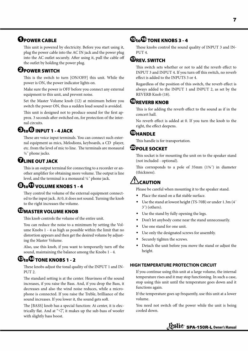
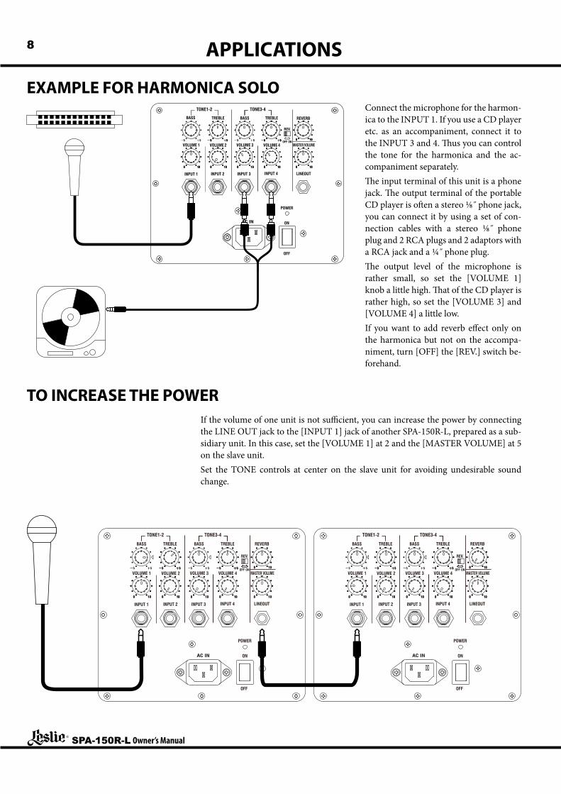
EXAMPLE FOR HARMONICA SOLOConnect the microphone for the harmon-ica to the INPUT 1. If you use a CD player etc. as an accompaniment, connect it to the INPUT 3 and 4. Thus you can control the tone for the harmonica and the ac-companiment separately.The input terminal of this unit is a phone jack. The output terminal of the portable CD player is often a stereo 1/8˝ phone jack, you can connect it by using a set of con-nection cables with a stereo 1/8˝ phone plug and 2 RCA plugs and 2 adaptors with a RCA jack and a 1/4˝ phone plug.The output level of the microphone is rather small, so set the [VOLUME 1] knob a little high. That of the CD player is rather high, so set the [VOLUME 3] and [VOLUME 4] a little low.If you want to add reverb effect only on the harmonica but not on the accompa-niment, turn [OFF] the [REV.] switch be-forehand.
TO INCREASE THE POWER
TONE1-2
BASS TREBLE
REV.
VOLUME 1
INPUT 1 INPUT 2 INPUT 3
VOLUME 2
TONE3-4
VOLUME 3 VOLUME 4
INPUT 4 LINEOUT
MASTER VOLUME
POWER
AC IN ON
OFF
ONOFF
BASS TREBLE REVERB
TONE1-2
BASS TREBLE
REV.
VOLUME 1
INPUT 1 INPUT 2 INPUT 3
VOLUME 2
TONE3-4
VOLUME 3 VOLUME 4
INPUT 4 LINEOUT
MASTER VOLUME
POWER
AC IN ON
OFF
ONOFF
BASS TREBLE REVERB
If the volume of one unit is not sufficient, you can increase the power by connecting the LINE OUT jack to the [INPUT 1] jack of another SPA-150R-L, prepared as a sub-sidiary unit. In this case, set the [VOLUME 1] at 2 and the [MASTER VOLUME] at 5 on the slave unit.Set the TONE controls at center on the slave unit for avoiding undesirable sound change.
9
SPA-150R-L Owner’s Manual
EXAMPLE: HARMONICA ENSEMBLE
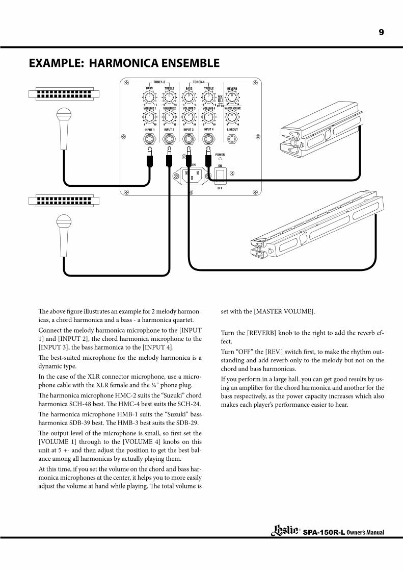
The above figure illustrates an example for 2 melody harmon-icas, a chord harmonica and a bass - a harmonica quartet.Connect the melody harmonica microphone to the [INPUT 1] and [INPUT 2], the chord harmonica microphone to the [INPUT 3], the bass harmonica to the [INPUT 4].The best-suited microphone for the melody harmonica is a dynamic type.In the case of the XLR connector microphone, use a micro-phone cable with the XLR female and the 1/4˝ phone plug.The harmonica microphone HMC-2 suits the “Suzuki” chord harmonica SCH-48 best. The HMC-4 best suits the SCH-24.The harmonica microphone HMB-1 suits the “Suzuki” bass harmonica SDB-39 best. The HMB-3 best suits the SDB-29.The output level of the microphone is small, so first set the [VOLUME 1] through to the [VOLUME 4] knobs on this unit at 5 +- and then adjust the position to get the best bal-ance among all harmonicas by actually playing them.At this time, if you set the volume on the chord and bass har-monica microphones at the center, it helps you to more easily adjust the volume at hand while playing. The total volume is
set with the [MASTER VOLUME].
Turn the [REVERB] knob to the right to add the reverb ef-fect.Turn “OFF” the [REV.] switch first, to make the rhythm out-standing and add reverb only to the melody but not on the chord and bass harmonicas.If you perform in a large hall. you can get good results by us-ing an amplifier for the chord harmonica and another for the bass respectively, as the power capacity increases which also makes each player’s performance easier to hear.
SPA-150R-L Owner’s Manual
10
EXAMPLE: MELODION ENSEMBLE
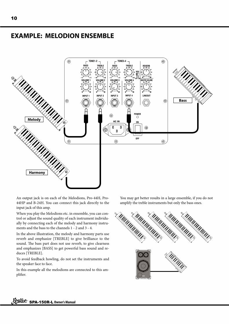
An output jack is on each of the Melodions, Pro-44H, Pro-44HP and B-24H. You can connect this jack directly to the input jack of this amp.When you play the Melodions etc. in ensemble, you can con-trol or adjust the sound quality of each instrument individu-ally by connecting each of the melody and harmony instru-ments and the bass to the channels 1 - 2 and 3 - 4.In the above illustration, the melody and harmony parts use reverb and emphasize [TREBLE] to give brilliance to the sound. The bass part does not use reverb, to give clearness and emphasizes [BASS] to get powerful bass sound and re-duces [TREBLE].To avoid feedback howling, do not set the instruments and the speaker face to face.In this example all the melodions are connected to this am-plifier.
You may get better results in a large ensemble, if you do not amplify the treble instruments but only the bass ones.
Melody
Harmony
Bass
11
SPA-150R-L Owner’s Manual
EXAMPLE: MELODION AND GUITAR DUO
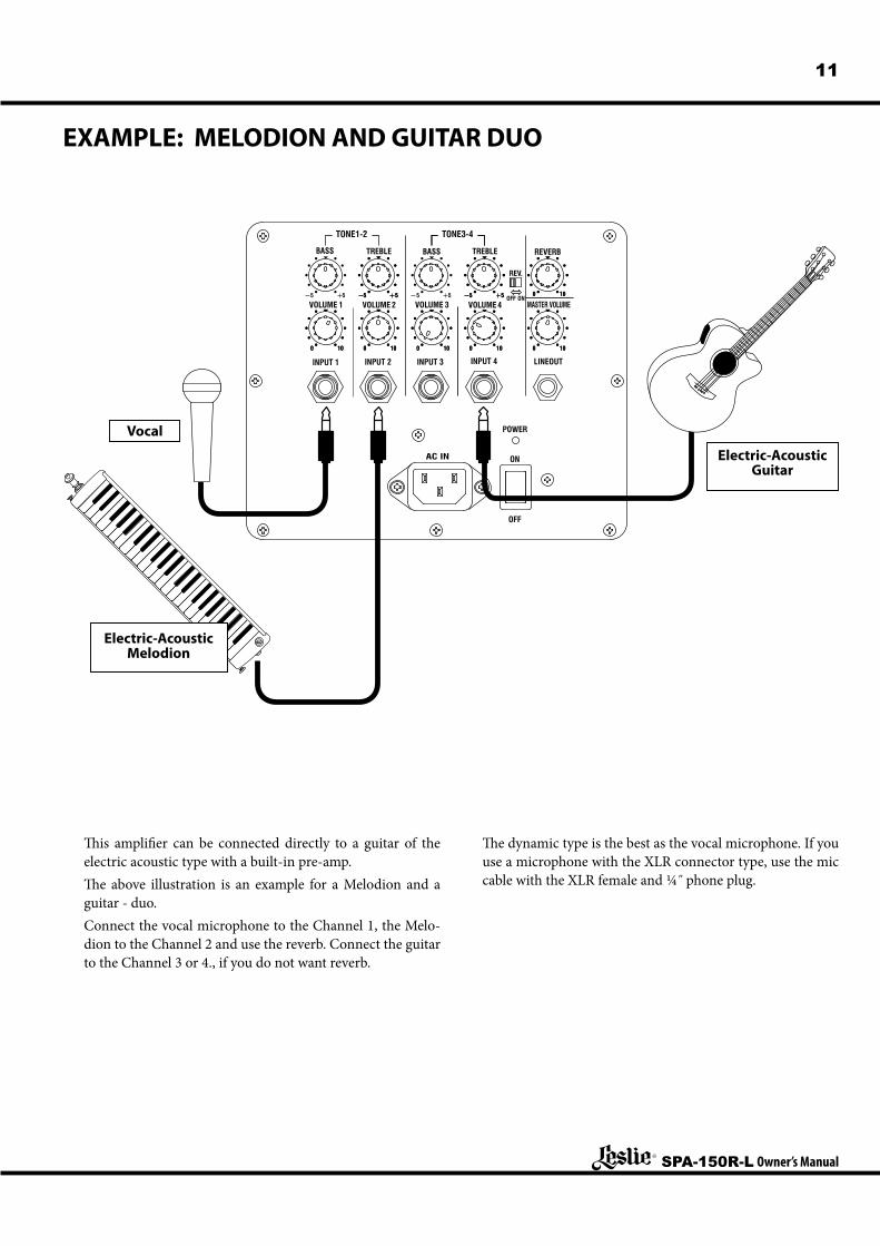
This amplifier can be connected directly to a guitar of the electric acoustic type with a built-in pre-amp.The above illustration is an example for a Melodion and a guitar - duo.Connect the vocal microphone to the Channel 1, the Melo-dion to the Channel 2 and use the reverb. Connect the guitar to the Channel 3 or 4., if you do not want reverb.
The dynamic type is the best as the vocal microphone. If you use a microphone with the XLR connector type, use the mic cable with the XLR female and 1/4˝ phone plug.
Vocal
Electric-Acoustic Melodion
Electric-Acoustic Guitar
SPA-150R-L Owner’s Manual
12
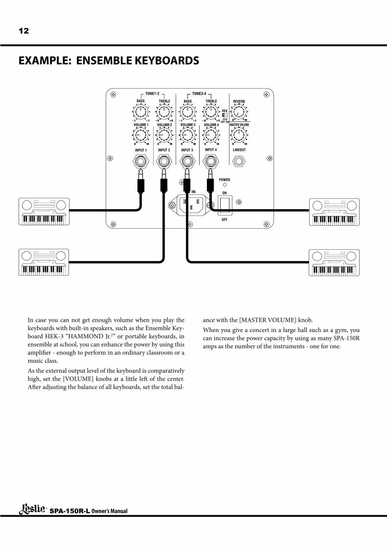
EXAMPLE: ENSEMBLE KEYBOARDS
In case you can not get enough volume when you play the keyboards with built-in speakers, such as the Ensemble Key-board HEK-3 “HAMMOND Jr.2” or portable keyboards, in ensemble at school, you can enhance the power by using this amplifier - enough to perform in an ordinary classroom or a music class.As the external output level of the keyboard is comparatively high, set the [VOLUME] knobs at a little left of the center. After adjusting the balance of all keyboards, set the total bal-
ance with the [MASTER VOLUME] knob.When you give a concert in a large hall such as a gym, you can increase the power capacity by using as many SPA-150R amps as the number of the instruments - one for one.
13
SPA-150R-L Owner’s Manual
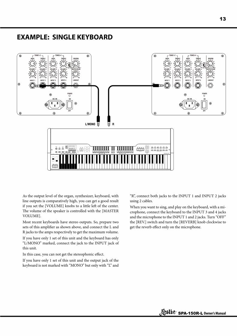
EXAMPLE: SINGLE KEYBOARD
TONE1-2
BASS TREBLE
REV.
VOLUME 1
INPUT 1 INPUT 2 INPUT 3
VOLUME 2
TONE3-4
VOLUME 3 VOLUME 4
INPUT 4 LINEOUT
MASTER VOLUME
POWER
AC IN ON
OFF
ONOFF
BASS TREBLE REVERB
TONE1-2
BASS TREBLE
REV.
VOLUME 1
INPUT 1 INPUT 2 INPUT 3
VOLUME 2
TONE3-4
VOLUME 3 VOLUME 4
INPUT 4 LINEOUT
MASTER VOLUME
POWER
AC IN ON
OFF
ONOFF
BASS TREBLE REVERB
BRAKE
LESLIE
ON FAST
SECOND THIRD
PERCUSSION
FAST SOFT
M.BASS SPLIT
REVERB USER
DRAWBARS PEDAL DRAWBARS DRAWBARSPITCH BEND MODULATION
PARAM.
1 / 3 / 4 /2 /
VALUE
MASTERVOLUME
TUBEOVERDRIVETONE
0 10 MIN MAX MIN MAX
MIN MAX MIN MAX MIN MAX MIN MAX MIN MAX MIN MAX
CONTROL TONE TYPE TUBE AMP PLAYREC/JUMPBANK MENU/EXIT
PAGE
UPPER B LOWER A
VIBRATOAND
CHORUS
V-3
V-2 V-1
C-2 C-3
C-1
PRESETS BA
UPPER LOWER
VIBRATO & CHORUS
DEMO
UPPER 1 UPPER 2 UPPER 3 LOWER 1 LOWER 2 PEDAL
ASSIGNABLE CONTROLLER
L/MONO R
As the output level of the organ, synthesizer, keyboard, with line outputs is comparatively high, you can get a good result if you set the [VOLUME] knobs to a little left of the center. The volume of the speaker is controlled with the [MASTER VOLUME].Most recent keyboards have stereo outputs. So, prepare two sets of this amplifier as shown above, and connect the L and R jacks to the amps respectively to get the maximum volume.If you have only 1 set of this unit and the keyboard has only “L/MONO” marked, connect the jack to the INPUT jack of this unit.In this case, you can not get the stereophonic effect.If you have only 1 set of this unit and the output jack of the keyboard is not marked with “MONO” but only with “L” and
“R”, connect both jacks to the INPUT 1 and INPUT 2 jacks using 2 cables.When you want to sing, and play on the keyboard, with a mi-crophone, connect the keyboard to the INPUT 3 and 4 jacks and the microphone to the INPUT 1 and 2 jacks. Turn “OFF” the [REV.] switch and turn the [REVERB] knob clockwise to get the reverb effect only on the microphone.
SPA-150R-L Owner’s Manual
14
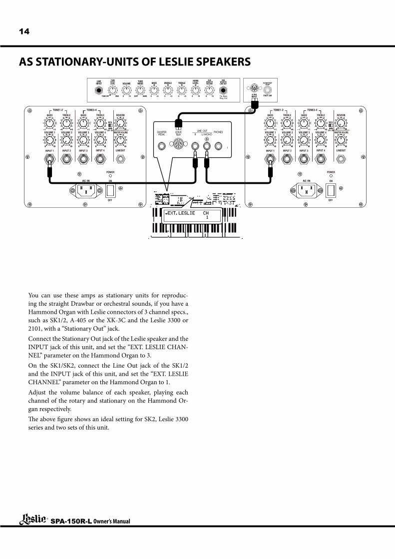
AS STATIONARY-UNITS OF LESLIE SPEAKERS
You can use these amps as stationary units for reproduc-ing the straight Drawbar or orchestral sounds, if you have a Hammond Organ with Leslie connectors of 3 channel specs., such as SK1/2, A-405 or the XK-3C and the Leslie 3300 or 2101, with a “Stationary Out” jack.Connect the Stationary Out jack of the Leslie speaker and the INPUT jack of this unit, and set the “EXT. LESLIE CHAN-NEL” parameter on the Hammond Organ to 3.On the SK1/SK2, connect the Line Out jack of the SK1/2 and the INPUT jack of this unit, and set the “EXT. LESLIE CHANNEL” parameter on the Hammond Organ to 1.Adjust the volume balance of each speaker, playing each channel of the rotary and stationary on the Hammond Or-gan respectively.The above figure shows an ideal setting for SK2, Leslie 3300 series and two sets of this unit.
LINEINPUT
TUBEMODE
HORNLEVELBASS MIDDLE TREBLEVOLUME
DRIVELEVEL
TUBE
TUBE OFF MAX 100 100 10 Tip :BassRing :Full
0HARDSOFT +5-5 +5-5 +5-5
WOOFERVOLUME
SUBWOOFERLINE OUT
SUB
TONE1-2
BASS TREBLE
REV.
VOLUME 1
INPUT 1 INPUT 2 INPUT 3
VOLUME 2
TONE3-4
VOLUME 3 VOLUME 4
INPUT 4 LINEOUT
MASTER VOLUME
POWER
AC IN ON
OFF
ONOFF
BASS TREBLE REVERB
TONE1-2
BASS TREBLE
REV.
VOLUME 1
INPUT 1 INPUT 2 INPUT 3
VOLUME 2
TONE3-4
VOLUME 3 VOLUME 4
INPUT 4 LINEOUT
MASTER VOLUME
POWER
AC IN ON
OFF
ONOFF
BASS TREBLE REVERB
15SPECIFICATIONSSpeakers
25cm (10 inch) high-power woofer, 2 - 10cm (4 inch) tweeter
Type2-way, Bass reflex enclosure
Output Power150W (music), 200W (peak)
Maximum Sound Pressure Level119dB SPL (1m)
Frequency Range45Hz - 15kHz
ControlVOLUME(1 - 4), BASS/TREBLE(1-2, 3-4), REVERB, REV., MASTER VOLUME, POWER
Tone ControlChannel 1-2, 3-4 individualBASS: ±8dB at 50Hz, TREBLE: ±10dB at 10kHz
ReverbDigital Reverb (Channel 3-4 is switchable)
ConnectionsINPUT 1 - 4
sensitivity: -40dBu(8mV) - +16dBu(5V), impedance: 50kW, mono phone jack
LINE OUToutput level: 0dBu (0.775V), impedance: 1kW, mono phone jack
Power RequirementsAC100 - 240V 50/60Hz
Power Consumption45W
DimensionsW32 x H61 x D31 cm / W12.5 x H24 x D12.2 inch
Weight15 kg / 33 lbs
OthersSpeaker stand (ø35mm / 13/8 DIA) correspondence
MAIN FEATURESu A high quality class-D digital amplifier is mounted in this
unit. Thus, it gives a very high quality tone from low vol-ume to the full power. At the same time, we have success-fully reduced both the power consumption and the total weight.
u The cabinet, exclusively designed for the special 25 cm (10 inch) high power speaker, is carefully tuned acousti-cally. As the result, powerful bass sound is expected as if from a large size speaker.
NOTE: In case this unit is used on the stand etc. or, depending on the environment, the bass sound may be insufficient.
u There are 4 channel inputs, all of which correspond from the microphone to the line. So it is possible to use this unit for various purposes as the external amplifiers for ensembles, keyboards, etc.
u This unit has a built-in digital reverb. So it is ideal for playing harmonicas and also as a vocal amplifier.
u The tone control is equipped in 2 independent groups: Channel 1 - 2 and Channel 3 - 4.
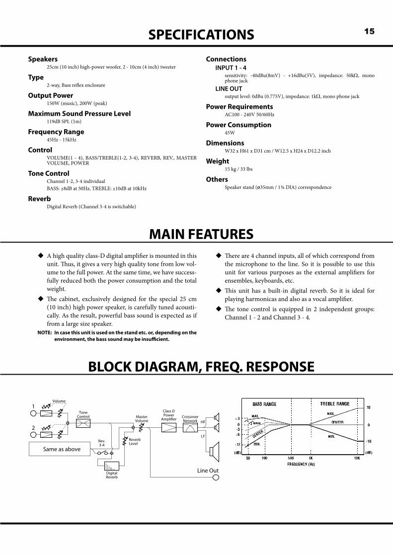
BLOCK DIAGRAM, FREQ. RESPONSE
Same as above
1
2
Volume
Tone Control Master
Volume
Line Out
Reverb Level
Digital Reverb
Rev.3-4
Class DPower
Ampli�er Crossover Network HF
LF
Printed in Japan00457-50040 V1.00-110620
SERVICEHammond maintains a policy of continuously improving and upgrading its instruments and therefore reserves the right to change specifications without notice. Although every attempt has been made to insure the accuracy of the descriptive contents of this Manual, total accuracy cannot be guaranteed.Should the owner require further assistance, inquiries should first be made to your Authorized Hammond Dealer.If you still need further assistance, contact Hammond at the following addresses:
In the United States Contact:
HAMMOND SUZUKI USA, Inc.733 Annoreno Dr.Addison, IL 60101
UNITED STATES
In Europe contact:
HAMMOND SUZUKI EUROPE B. V.IR. D. S. Tuynmanweg 4A
4131 PN VianenTHE NETHERLANDS
All other countries contact:
HAMMOND SUZUKI Ltd.25-11, Ryoke 2 Chome,Naka-ku, Hamamatsu430-0852 (Shizuoka)
JAPAN
E-mail: [email protected] site: www.hammondorganco.com
E-mail: [email protected] site: www.hammond.eu
E-mail: [email protected] site: www.suzuki-music.co.jp
Technical materials are available and can be obtained by mailing a request to the appropriate address listed above marked ATTENTION: SERVICE DEPARTMENT.
Manufacturer:SUZUKI MUSICAL INSTRUMENT MFG. CO., Ltd.
25-12, Ryoke 2 Chome, Naka-ku,Hamamatsu 430-0852 (Shizuoka)
JAPAN