Embed Size (px)
Citation preview

Leica GS10/GS15User Manual
Version 8.0English

GS10/GS15, Introduction 2
IntroductionPurchase Congratulations on the purchase of a Leica GS10/GS15.
This manual contains important safety directions as well as instructions for setting up the product and operating it. Refer to "1 Safety Directions" for further information.Read carefully through the User Manual before you switch on the product.
Product Identification
The model and serial number of your product are indicated on the type plate.Always refer to this information when you need to contact your agency or Leica Geosystems authorised service workshop.
Trademarks • Windows is a registered trademark of Microsoft Corporation in the United States and other countries
• Bluetooth® is a registered trademark of Bluetooth SIG, Inc.• SD Logo is a trademark of SD-3C, LLC.All other trademarks are the property of their respective owners.
Validity of this manual
This manual applies to the GS10/GS15.
Available documentation
Refer to the following resources for all GS10/GS15 documentation/software:• the Leica USB documentation card• https://myworld.leica-geosystems.com
Name Description/Format
GS10/GS15 Quick Guide
Provides an overview of the product together with tech-nical data and safety directions. Intended as a quick reference guide.
GS10/GS15 User Manual
All instructions required in order to operate the product to a basic level are contained in the User Manual. Provides an overview of the product together with tech-nical data and safety directions.
-
Name Description/Format
Viva Series Technical Reference ManualandCaptivate Technical Reference Manual
Overall comprehensive guide to the product and applica-tion functions. Included are detailed descriptions of special software/hardware settings and software/hard-ware functions intended for technical specialists.
-

GS10/GS15, Introduction 3
myWorld@Leica Geosystems (https://myworld.leica-geosystems.com) offers a wide range of services, information and training material.With direct access to myWorld, you are able to access all relevant services whenever it is convenient for you, 24 hours a day, 7 days per week. This increases your efficiency and keeps you and your equipment instantly updated with the latest information from Leica Geosystems.
Service DescriptionmyProducts Add all products that you and your company own and explore your
world of Leica Geosystems: View detailed information on your prod-ucts and update your products with the latest software and keep up-to-date with the latest documentation.
myService View the current service status and full service history of your prod-ucts in Leica Geosystems service centres. Access detailed informa-tion on the services performed and download your latest calibration certificates and service reports.
mySupport View the current service status and full service history of your prod-ucts in Leica Geosystems service centres. Access detailed informa-tion on the services performed and download your latest calibration certificates and service reports.
myTraining Enhance your product knowledge with Leica Geosystems Campus - Information, Knowledge, Training. Study the latest online training material on your products and register for seminars or courses in your country.
myTrustedServices
Add your subscriptions and manage users for Leica Geosystems Trusted Services, the secure software services, that assist you to optimise your workflow and increase your efficiency.

GS10/GS15, Table of Contents 4
Table of ContentsIn this manual Chapter Page
1 Safety Directions 61.1 General Introduction 61.2 Definition of Use 71.3 Limits of Use 71.4 Responsibilities 81.5 Hazards of Use 81.6 Electromagnetic Compatibility EMC 121.7 FCC Statement, Applicable in U.S. 131.8 ICES-003 Statement, Applicable in Canada 14
2 Description of the System 152.1 System Components 152.2 System Concept 15
2.2.1 Software Concept 152.2.2 Power Concept 162.2.3 Data Storage Concept 16
2.3 Container Contents 172.4 Instrument Components 21
3 User Interface 223.1 Keyboard 223.2 Operating Principles 24
4 Operation 254.1 Equipment Setup 25
4.1.1 Setting up as a Post-Processing Base 254.1.2 Setting up as a Real-Time Base 294.1.3 Setting up as a Real-Time Rover 334.1.4 Using the Backpack 374.1.5 Fixing the Field Controller to a Holder and Pole 384.1.6 Connecting to a Personal Computer 404.1.7 Connecting to the Web Server 434.1.8 Configuring the Instrument 45
4.2 Batteries 464.2.1 Operating Principles 464.2.2 Battery for GS10 464.2.3 Battery for GS15 47
4.3 Working with the Memory Device 484.4 Working with the RTK Device 50
4.4.1 GS10 504.4.2 GS15 53
4.5 LED Indicators on GS10/GS15 564.6 Guidelines for Correct Results with GNSS Surveys 57
5 Care and Transport 585.1 Transport 585.2 Storage 585.3 Cleaning and Drying 59

GS10/GS15, Table of Contents 5
6 Technical Data 606.1 GS10/GS15 Technical Data 60
6.1.1 Tracking Characteristics 606.1.2 Accuracy 606.1.3 Technical Data 61
6.2 Antennas Technical Data 636.3 Conformity to National Regulations 66
6.3.1 GS10 666.3.2 GS15 676.3.3 GFU27, SATEL Satelline M3-TR1 686.3.4 GFU28, Telit UC864-G 696.3.5 GFU29, Cinterion PXS8 706.3.6 GFU30, SATEL Satelline M3-TR4 716.3.7 SLR5, SATEL SATELLINE M3-TR1 726.3.8 SLR6, SATEL SATELLINE M3-TR4 736.3.9 SLG1, Telit UC864-G 746.3.10 Dangerous Goods Regulations 75
7 Software Licence Agreement 76
Appendix A Pin Assignments and Sockets 77A.1 GS10 77A.2 GS15 78
GS10/GS15, Safety Directions 6
1 Safety Directions1.1 General Introduction
Description The following directions enable the person responsible for the product, and the person who actually uses the equipment, to anticipate and avoid operational hazards.
The person responsible for the product must ensure that all users understand these directions and adhere to them.
About Warning Messages
Warning messages are an essential part of the safety concept of the instrument. They appear wherever hazards or hazardous situations can occur.
Warning messages...• make the user alert about direct and indirect hazards concerning the use of the
product.• contain general rules of behaviour.
For the users‘ safety, all safety instructions and safety messages shall be strictly observed and followed! Therefore, the manual must always be available to all persons performing any tasks described herein.
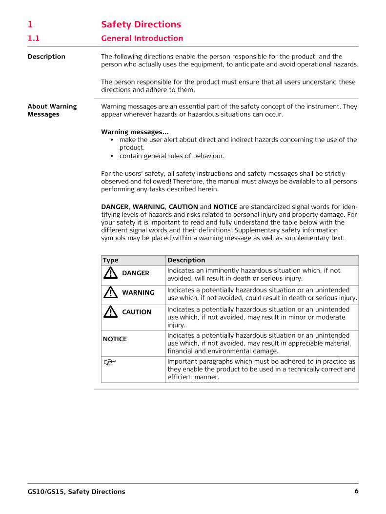
DANGER, WARNING, CAUTION and NOTICE are standardized signal words for iden-tifying levels of hazards and risks related to personal injury and property damage. For your safety it is important to read and fully understand the table below with the different signal words and their definitions! Supplementary safety information symbols may be placed within a warning message as well as supplementary text.
Type Description
� DANGER Indicates an imminently hazardous situation which, if not avoided, will result in death or serious injury.
� WARNING Indicates a potentially hazardous situation or an unintended use which, if not avoided, could result in death or serious injury.
� CAUTION Indicates a potentially hazardous situation or an unintended use which, if not avoided, may result in minor or moderate injury.
NOTICE Indicates a potentially hazardous situation or an unintended use which, if not avoided, may result in appreciable material, financial and environmental damage.
Important paragraphs which must be adhered to in practice as they enable the product to be used in a technically correct and efficient manner.

GS10/GS15, Safety Directions 7
1.2 Definition of Use
Intended use • Computing with software.• Carrying out measurement tasks using various GNSS measuring techniques.• Recording GNSS and point related data.• Data communication with external appliances.• Measuring raw data and computing coordinates using carrier phase and code signal
from GNSS satellites.
Reasonably foreseeable misuse
• Use of the product without instruction.• Use outside of the intended use and limits.• Disabling safety systems.• Removal of hazard notices.• Opening the product using tools, for example screwdriver, unless this is permitted
for certain functions.• Modification or conversion of the product.• Use after misappropriation.• Use of products with obvious damages or defects.• Use with accessories from other manufacturers without the prior explicit approval
of Leica Geosystems.• Inadequate safeguards at the working site.• Controlling of machines, moving objects or similar monitoring application without
additional control and safety installations.
1.3 Limits of Use
Environment Suitable for use in an atmosphere appropriate for permanent human habitation: not suitable for use in aggressive or explosive environments.
� DANGER Local safety authorities and safety experts must be contacted before working in hazardous areas, or close to electrical installations or similar situations by the person in charge of the product.

GS10/GS15, Safety Directions 8
1.4 Responsibilities
Manufacturer of the product
Leica Geosystems AG, CH-9435 Heerbrugg, hereinafter referred to as Leica Geosys-tems, is responsible for supplying the product, including the user manual and original accessories, in a safe condition.
Person responsible for the product
The person responsible for the product has the following duties:• To understand the safety instructions on the product and the instructions in the
user manual.• To ensure that it is used in accordance with the instructions.• To be familiar with local regulations relating to safety and accident prevention.• To inform Leica Geosystems immediately if the product and the application
becomes unsafe.• To ensure that the national laws, regulations and conditions for the operation of
e.g. radio transmitters or lasers are respected.• To ensure that the radio modem is not operated without the permission of the local
authorities on frequencies and/or output power levels other than those specifically reserved and intended for use without a specific permit.The internal and external radio modems have been designed to operate on frequency ranges and output power ranges, the exact use of which differs from one region and/or country to another.
1.5 Hazards of Use
� CAUTION Watch out for erroneous measurement results if the product has been dropped or has been misused, modified, stored for long periods or transported.Precautions:Periodically carry out test measurements and perform the field adjustments indicated in the user manual, particularly after the product has been subjected to abnormal use as well as before and after important measurements.
� DANGER Because of the risk of electrocution, it is dangerous to use poles, levelling staffs and extensions in the vicinity of electrical installations such as power cables or electrical railways.Precautions:Keep at a safe distance from electrical installations. If it is essential to work in this environment, first contact the safety authorities responsible for the electrical instal-lations and follow their instructions.
� WARNING During dynamic applications, for example stakeout procedures there is a danger of accidents occurring if the user does not pay attention to the environmental conditions around, for example obstacles, excavations or traffic.Precautions:The person responsible for the product must make all users fully aware of the existing dangers.

GS10/GS15, Safety Directions 9
� WARNING Inadequate securing of the working site can lead to dangerous situations, for example in traffic, on building sites and at industrial installations.Precautions:Always ensure that the working site is adequately secured. Adhere to the regulations governing safety, accident prevention and road traffic.
� CAUTION If the accessories used with the product are not properly secured and the product is subjected to mechanical shock, for example blows or falling, the product may be damaged or people can sustain injury.Precautions:When setting-up the product, make sure that the accessories are correctly adapted, fitted, secured, and locked in position.Avoid subjecting the product to mechanical stress.
� WARNING Incorrect fastening of the external antenna to vehicles or transporters poses the risk of the equipment being broken by mechanical influence, vibration or airstream. This may result in accident and physical injury.Precautions:Attach the external antenna professionally. The external antenna must be secured additionally, for example by use of a safety cord. Ensure that the mounting device is correctly mounted and able to carry the weight of the external antenna (>1 kg) safely.
� WARNING If the product is used with accessories, for example masts, staffs, poles, you may increase the risk of being struck by lightning.Precautions:Do not use the product in a thunderstorm.
� DANGER If the product is used with accessories, for example on masts, staffs, poles, you may increase the risk of being struck by lightning. Danger from high voltages also exists near power lines. Lightning, voltage peaks, or the touching of power lines can cause damage, injury and death.Precautions:• Do not use the product in a thunderstorm as you can increase the risk of being
struck by lightning.• Be sure to remain at a safe distance from electrical installations. Do not use the
product directly under or close to power lines. If it is essential to work in such an environment contact the safety authorities responsible for electrical installations and follow their instructions.
• If the product has to be permanently mounted in an exposed location, it is advis-able to provide a lightning conductor system. A suggestion on how to design a lightning conductor for the product is given below. Always follow the regulations in force in your country regarding grounding antennas and masts. These installations must be carried out by an authorised specialist.
• To prevent damages due to indirect lightning strikes (voltage spikes) cables, for example for antenna, power source or modem should be protected with appro-priate protection elements, like a lightning arrester. These installations must be carried out by an authorised specialist.
• If there is a risk of a thunderstorm, or if the equipment is to remain unused and unattended for a long period, protect your product additionally by unplugging all systems components and disconnecting all connecting cables and supply cables, for example, instrument - antenna.

GS10/GS15, Safety Directions 10
Lightning conductors
Suggestion for design of a lightning conductor for a GNSS system:1) On non-metallic structures
Protection by air terminals is recommended. An air terminal is a pointed solid or tubular rod of conducting material with proper mounting and connection to a conductor. The position of four air terminals can be uniformly distributed around the antenna at a distance equal to the height of the air terminal.The air terminal diameter should be 12 mm for copper or 15 mm for aluminium. The height of the air terminals should be 25 cm to 50 cm. All air terminals should be connected to the down conductors. The diameter of the air terminal should be kept to a minimum to reduce GNSS signal shading.
2) On metallic structuresProtection is as described for non-metallic structures, but the air terminals can be connected directly to the conducting structure without the need for down conduc-tors.
Air terminal arrangement, plan view
Grounding the instrument/antenna
� CAUTION During the transport, shipping or disposal of batteries it is possible for inappropriate mechanical influences to constitute a fire hazard.Precautions:Before shipping the product or disposing of it, discharge the batteries by running the product until they are flat.When transporting or shipping batteries, the person in charge of the product must ensure that the applicable national and international rules and regulations are observed. Before transportation or shipping contact your local passenger or freight transport company.
� WARNING High mechanical stress, high ambient temperatures or immersion into fluids can cause leakage, fire or explosions of the batteries.Precautions:Protect the batteries from mechanical influences and high ambient temperatures. Do not drop or immerse batteries into fluids.
a) Antennab) Support structurec) Air terminalGS_039
a
b
c
a) Antennab) Lightning conductor arrayc) Antenna/instrument connectiond) Metallic maste) Connection to earthGS_040
e
d
c
ab

GS10/GS15, Safety Directions 11
� WARNING If battery terminals are short circuited e.g. by coming in contact with jewellery, keys, metalized paper or other metals, the battery can overheat and cause injury or fire, for example by storing or transporting in pockets.Precautions:Make sure that the battery terminals do not come into contact with metallic objects.
� WARNING If the product is improperly disposed of, the following can happen:• If polymer parts are burnt, poisonous gases are produced which may impair health.• If batteries are damaged or are heated strongly, they can explode and cause
poisoning, burning, corrosion or environmental contamination.• By disposing of the product irresponsibly you may enable unauthorised persons to
use it in contravention of the regulations, exposing themselves and third parties to the risk of severe injury and rendering the environment liable to contamination.
Precautions:
Product-specific treatment and waste management information can be downloaded from the Leica Geosystems home page at http://www.leica-geosystems.com/treatment or received from your Leica Geosystems distributor.
� WARNING Only Leica Geosystems authorised service workshops are entitled to repair these prod-ucts.
The product must not be disposed with household waste.Dispose of the product appropriately in accordance with the national regulations in force in your country.Always prevent access to the product by unauthorised personnel.

GS10/GS15, Safety Directions 12
1.6 Electromagnetic Compatibility EMC
Description The term Electromagnetic Compatibility is taken to mean the capability of the product to function smoothly in an environment where electromagnetic radiation and electro-static discharges are present, and without causing electromagnetic disturbances to other equipment.
� WARNING Electromagnetic radiation can cause disturbances in other equipment.Although the product meets the strict regulations and standards which are in force in this respect, Leica Geosystems cannot completely exclude the possibility that other equipment may be disturbed.
� CAUTION There is a risk that disturbances may be caused in other equipment if the product is used with accessories from other manufacturers, for example field computers, personal computers or other electronic equipment, non-standard cables or external batteries.Precautions:Use only the equipment and accessories recommended by Leica Geosystems. When combined with the product, they meet the strict requirements stipulated by the guide-lines and standards. When using computers or other electronic equipment, pay atten-tion to the information about electromagnetic compatibility provided by the manufac-turer.
� CAUTION Disturbances caused by electromagnetic radiation can result in erroneous measure-ments.Although the product meets the strict regulations and standards which are in force in this respect, Leica Geosystems cannot completely exclude the possibility that the product may be disturbed by intense electromagnetic radiation, for example, near radio transmitters, two-way radios or diesel generators.Precautions:Check the plausibility of results obtained under these conditions.
� CAUTION If the product is operated with connecting cables attached at only one of their two ends, for example external supply cables, interface cables, the permitted level of elec-tromagnetic radiation may be exceeded and the correct functioning of other products may be impaired. Precautions:While the product is in use, connecting cables, for example product to external battery, product to computer, must be connected at both ends.
Radios or Digital Cellular Phones
Use of product with radio or digital cellular phone devices:
� WARNING Electromagnetic fields can cause disturbances in other equipment, in installations, in medical devices, for example pacemakers or hearing aids and in aircraft. It can also affect humans and animals.Precautions:Although the product meets the strict regulations and standards which are in force in this respect, Leica Geosystems cannot completely exclude the possibility that other equipment can be disturbed or that humans or animals can be affected.• Do not operate the product with radio or digital cellular phone devices in the vicinity
of filling stations or chemical installations, or in other areas where an explosion hazard exists.
• Do not operate the product with radio or digital cellular phone devices near to medical equipment.
• Do not operate the product with radio or digital cellular phone devices in aircraft.

GS10/GS15, Safety Directions 13
1.7 FCC Statement, Applicable in U.S.
The greyed paragraph below is only applicable for products without radio.
� WARNING
� WARNING Changes or modifications not expressly approved by Leica Geosystems for compliance could void the user's authority to operate the equipment.
Labelling GS10
Labelling GS15
This equipment has been tested and found to comply with the limits for a Class B digital device, pursuant to part 15 of the FCC rules.These limits are designed to provide reasonable protection against harmful interfer-ence in a residential installation.This equipment generates, uses and can radiate radio frequency energy and, if not installed and used in accordance with the instructions, may cause harmful interference to radio communications. However, there is no guarantee that interference will not occur in a particular installation.If this equipment does cause harmful interference to radio or television reception, which can be determined by turning the equipment off and on, the user is encouraged to try to correct the interference by one or more of the following measures:• Reorient or relocate the receiving antenna.• Increase the separation between the equipment and the receiver.• Connect the equipment into an outlet on a circuit different from that to which the
receiver is connected.• Consult the dealer or an experienced radio/TV technician for help.
00112250_001000112250_00000011
0012250 001
R. . . . . . . . . . . . . . . . . .
Model: . . . . . . . . . . .Art.No.: . . . . . .Equi.No.: . . . . . . . . . . . . Power: . . . . . . . . . . . . . . . . . . . .Leica Geosystems AGCH-9435 HeerbruggManufactured: . . . . . Made in Switzerland
This device complies with part 15 of the FCC Rules. Operation is subject to the following two conditions: (1) This device may not cause harmful interference, and (2) this device must accept any interference received, including interference that may cause undesired operation.
S.No.: . . . . . .
FCC-ID: . . . - . . - . IC: . . . . . .
Contains transmitter module:FCC-ID: . . . - . . . . . . Bluetooth QPL: . . . . . .25
008607_002

GS10/GS15, Safety Directions 14
Labelling internal battery GEB212
Labelling internal battery GEB222
1.8 ICES-003 Statement, Applicable in Canada
� WARNING This Class (B) digital apparatus complies with Canadian ICES-003.Cet appareil numérique de la classe (B) est conforme à la norme NMB-003 du Canada.
005044_001
005043_001

GS10/GS15, Description of the System 15
2 Description of the System2.1 System Components
Main components
Instruments Depending on the satellite systems and signals configured, a maximum number of 555 channels is allocated.
2.2 System Concept2.2.1 Software Concept
Description All instruments use the same software concept.
Software for all GS GNSS instruments
Software upload Uploading GS firmware can take some time. Ensure that the battery is at least 75% full before beginning the upload, and do not remove the battery during the upload process.
Component DescriptionInstrument To calculate a position from the computed ranges to all
visible GNSS (Global Navigation Satellite System) satellites.Web server Web-based tool to preprogram the GNSS instrument.Antenna To receive the satellite signals from the GNSS satellites.Leica Geo Office, Leica Infinity
The office software including a series of help programs which support working with Leica instruments.
Instrument DescriptionGS10/GS15 GPS, GLONASS, BeiDou and Galileo GNSS receiver, multi-
frequency, SBAS (EGNOS, WAAS, GAGAN, MSAS, QZSS), code and phase, real-time capable
Software type DescriptionGS firmware(GS_xx.fw)
This important software covers all functions of the instru-ment.
The Web server application is integrated into the firmware and cannot be deleted.The English language is integrated into the firmware and cannot be deleted.
Language software(WEB_LANG.sxx)
Numerous languages are available for the Web server applica-tion.
The English language is the default language. One language is chosen as the active language.
Software for DescriptionAll GS models The software can be uploaded using the Leica Web server
application or myWorld@Leica Geosystems.
Ensure that a Leica SD card is inserted into the GS instrument before starting the upload. Refer to "4.3 Working with the Memory Device".

GS10/GS15, Description of the System 16
2.2.2 Power Concept
General Use the batteries, chargers and accessories recommended by Leica Geosystems to ensure the correct functionality of the instrument.
Power options Power for the instrument can be supplied either internally or externally. Up to two external power supplies can be connected.
For permanent operations use Uninterruptible Power Supply units as a back-up in a main power failure.
2.2.3 Data Storage Concept
Description Data (Leica GNSS raw data and RINEX data) can be recorded on the SD card.
Memory device
Unplugging connecting cables, removing the data storage device or interrupting the power supply during the measurement can cause loss of data. Only remove the data storage device, unplug connecting cables or interrupt the power supply when the GS GNSS instrument is switched off.
SD cards can directly be used in an OMNI drive as supplied by Leica Geosystems. Other PC card drives can require an adaptor.
Internal power supply: Two batteries (for GS10: GEB222; for GS15: GEB212) fit into the instrument.
If one battery fails, a system shutdown of the GS10/GS15 GNSS instrument will be prevented by switching over directly to the second battery.
External power supply: GEB371 battery connected via a cable.ORCar battery connected via a converter cable supplied by Leica Geosystems.OR10.5 V-28 V DC power supply via a converter cable supplied by Leica Geosystems.OR110 V/240 V AC to 12 V DC power supply unit, supplied by Leica Geosystems.
SD card: All GS GNSS instruments have an SD card slot fitted as standard. An SD card can be inserted and removed. Available capacity: 1 GB.
While other SD cards can be used, Leica Geosystems recommends to only use Leica SD cards and is not responsible for data loss or any other error that can occur while using a non-Leica card.

GS10/GS15, Description of the System 17
2.3 Container Contents
Container for GS10 instrument and accessories part 1 of 2
a) GDC221 car adapter cableb) Antenna and GAD31 adapterc) Cablesd) Adjustment tool and allen keye) Stylusf) SD card and coverg) RTK phone or radio modemh) GEB212 or GEB311 batteryi) Height hookj) Tribrachk) Manual & USB documentation cardl) External batterym) Additional foam inlay piece (to be used with GS10 only)n) GS10 with radio modem attached or GS10 with additional foam inlay piece
009305_002
a
b
c
i
j
l
m
k
d
e
f
g
h
n

GS10/GS15, Description of the System 18
Container for GS10 instrument and accessories part 2 of 2
a) GAD34 antenna arm or GAD46 double antenna armb) GHT36 base for telescopic rodc) GHT40 holder for GS receiversd) GRT146 carriere) GFU RTK modemf) GEB242 battery or GEB222 batteries (2pcs.)g) GHT63 clamph) GAT18 mobile antennai) GHT58 tripod bracket for GFUj) GAD32 telescopic rod and GAT1 or GAT2 radio antennask) GAD33 arm 15 cml) CS35 tablet or CS20 field controller with GHT66 holder or CS15 field controller with
GHT62 holder
009306_001
ab
c
i
j
l
k
d
e
f
g
h

GS10/GS15, Description of the System 19
Container for GS15 instrument and accessories part 1 of 2
a) GHT63 clampb) Manuals and USB documentation cardc) GEB212 or GEB311 batteriesd) GS15 antennae) GAT18 mobile antennaf) GAT21, GAT25 or GAT26 radio antennag) Tribrachh) CS15 field controller with GHT62 holder or CS20 field controller with GHT66 holder
or CS35 tableti) Height hookj) Cablesk) GDC221 car adapterl) RTK phone or radio modem for GS15m) SD cardsn) Styluso) GAD34 arm 3 cmp) TNC QN-adapterq) Allen key and adjustment tool
009307_002
abc
ij
k
d
d
e
f
g
hl
mnopq

GS10/GS15, Description of the System 20
Container for GS15 instrument and accessories part 2 of 2
a) GHT36 base for telescopic rodb) GAD108 armc) GFU RTK modemd) GAD32 telescopic rode) GAT1 or GAT2 radio antennasf) GEB212 or GEB311 batteriesg) GRT146 or GRT247 carrierh) GAD33 armi) GHT58 tripod bracket for GFUj) External battery
009308_001
a
b
c
j
i
d
e
h
f
g

GS10/GS15, Description of the System 21
2.4 Instrument Components
The instrument can be preprogrammed using the Web server application running from the instrument on a web browser of a Windows device. In this case, the instrument is turned on by holding down the ON/OFF button for 2 s or off by holding down the ON/OFF button for 2 s. A green steady light at the power LED indicates that the instru-ment is turned on.
GS10 components
GS15 components
A Bluetooth port is included inside all GS GNSS instruments to enable connectivity to the field controller.
a) Bluetooth antennab) Guide rail for clip-on-housing of a
device (available on both sides)c) Function buttond) ON/OFF buttone) LEMO port P3f) Power portg) Antenna porth) LED indicatorsi) Battery compartment A including SD
card compartmentj) Battery compartment Bk) LEMO port P2l) LEMO port P1 including USB port0012207_001
ba h i j k lc d e f g
a) RTK device compartment including port P3
b) RTK device LEDsc) Battery compartment 2d) LEDs, ON/OFF button and Function
buttone) LEMO port P1 including USB portf) QN-connector for external UHF or
digital cellular phone antennag) LEMO port P2h) Battery compartment 1 with SD card
sloti) Mechanical Reference Plane (MRP)0012208_001
a
c
b
d
e
f
g
h
i

GS10/GS15, User Interface 22
3 User Interface3.1 Keyboard
Keyboard GS10
Keyboard GS15
ON/OFF button
Function button All functions following described assume the GS10/GS15 is already on.
a) ON/OFF buttonb) Function buttonGS_082
ab
a) ON/OFF buttonb) Function buttonGS_080
a b
Button FunctionON/OFF If GS10/GS15 already off:
Turns on GS10/GS15 when held for 2 s.
While the GS10/GS15 is booting all three battery LEDs are lighted. Once the GS10/GS15 has started, the normal LED behaviour starts.
If GS10/GS15 already on:Turns off GS10/GS15 when held for 2 s.
All LEDs will shine red for 1 s-2 s and then are turned off.
Button FunctionFunction Press and hold button for <1 s.
If the GS10/GS15 is in:• base mode: The GS10/GS15 switches to be in rover
mode.• rover mode and in static mode: The GS10/GS15 switches
to be in base mode.• rover mode and in kinematic mode: The GS10/GS15
switches to be in base mode.Press and hold button for 3 s.If the GS10/GS15 is in:• base mode and a position is available: The RTK base LED
flashes green for 2 s.The GS10/GS15 takes the next available position and updates the coordinates of the currently stored RTK base position.
• base mode and no position is available: The RTK base LED flashes yellow for 2 s.

GS10/GS15, User Interface 23
Button combinations
• rover mode: No action.Press and hold button for 5 s.If the GS10/GS15 is in:• base mode: No action.• rover mode and configured for a dial-up or Ntrip connec-
tion: The RTK rover LED flashes green for 2 s. The GS10/GS15 will connect to the RTK base station or the Ntrip server configured.
• rover mode and not configured for a dial-up or Ntrip connection: No action.
Button Function
Button FunctionON/OFF Press and hold buttons for 1 s.
Function The current almanacs stored on the GNSS instrument are deleted and new almanacs are downloaded. The Position LED flashes red quickly three times.Press and hold buttons for 5 s.The Memory LED flashes red quickly three times. The SD card of the GNSS instrument is formatted. The Memory LED continues to flash red as the SD card is formatted.Press and hold buttons for 10 s.The System RAM on the GNSS instrument is formatted. Settings of all installed software will be deleted. All LEDs (except Battery LED and Bluetooth LED) flash red quickly three times. After the formatting the System RAM, the GNSS instrument is turned off.Press and hold buttons for 15 s.The registry of the GNSS instrument is deleted. Windows CE and communication settings will be reset to factory defaults. All LEDs (except Battery LED and Bluetooth LED) flash red quickly three times. After deleting the registry, the GNSS instrument is turned off.

GS10/GS15, User Interface 24
3.2 Operating Principles
Operating the instrument
The GS10/GS15 GNSS instrument is operated either by the pressing its buttons (ON/OFF button, function button) or by the field controller.Operation by buttonsThe GS10/GS15 GNSS instrument is operated by pressing its buttons. Refer to "3.1 Keyboard" for a detailed description of the buttons and their function.Operation by field controllerThe GS10/GS15 GNSS instrument is operated by the field controller using the Leica SmartWorx Viva/Leica Captivate software. Refer to the User Manual of the field controller for a detailed description of the keys and their function.
Turn on GS10/GS15 To turn on the instrument press and hold the Power button for 2 s.
Turn off GS10/GS15 To turn off the instrument:• press and hold the ON/OFF button for 2 s• confirm to power down the instrument when exiting the software on the field
controller

GS10/GS15, Operation 25
4 Operation4.1 Equipment Setup4.1.1 Setting up as a Post-Processing Base
Use The equipment setup described is used for static operations over markers.
Description The instrument can be programmed with the field controller before use which can then be omitted from the setup.
• The antenna is mounted directly using screw fitting. If using stub and adapter, procedures can vary slightly.
• When using the adapter and carrier, ensure that the antenna and the adapter assembly slide down the full length of the carrier stub. An incorrectly mounted antenna will have a direct effect on the results.
If the instrument is left in the container during use in high temperatures, the lid should be left open. Refer to the User Manual for operating and storage temperatures.
Use an external battery such as GEB371 to ensure operation for a full day.

GS10/GS15, Operation 26
Equipment setup - GS10
a) GNSS antenna AS05/AS10b) GRT146 carrierc) Tribrachd) Height hooke) GS10 instrumentf) 1.2 m antenna cableg) Tripodh) SD cardi) CompactFlash cardj) CS15 field controllerk) GEB212 batteryl) CS20 field controllerm) GEB331 batteriesn) GEB222 batterieso) CS35 tabletp) USB stick
0012252_001
a
bc
k
d
e
f
g
l
m
n
o
p
j
ih
h
h

GS10/GS15, Operation 27
Equipment setup - GS15
a) GS15 instrumentb) SD cardc) GEB212 batteriesd) GRT247 carriere) Tribrachf) Height hookg) Tripodh) GHT61 hand strapi) CompactFlash cardj) Utility hookk) CS20 field controllerl) GEB331 batteriesm) CS15 field controllern) GEB212 batteryo) CS35 field controllerp) USB stick
0012251_001
ab
ci
k
de
f
g
h
l
mnop
b
j
b

GS10/GS15, Operation 28
Equipment setup step-by-step
Step Description1. Set up the tripod.2. Mount and level the tribrach on the tripod.3. Ensure that the tribrach is over the marker.4. Place and lock the carrier in the tribrach.
GS10 GS155. Screw the GNSS antenna onto the
carrier.Insert the data storage device and the batteries into the GS15.
6. Check that the tribrach is still level. Screw the GS15 onto the carrier.7. Insert the batteries into the instru-
ment.Check that the tribrach is still level.
8. Insert the SD card into the instru-ment.
Insert the data storage device and the battery into the field controller.
9. Connect the instrument to the GNSS antenna using the antenna cable and port ANT on the instrument.
-
10. Switch on the field controller and connect it to the instrument if necessary.11. To hang the instrument on the tripod
leg, use the hook on the rear of the unit. Or place the instrument in the container.
To hang the field controller on the tripod leg, use the hook on the hand strap or use the utility hook. Refer to the User Manual of the field controller.
12. Insert the height hook into the carrier.13. Measure the antenna height using the height hook.14. Press the ON/OFF button on the instrument for at least 2 s to switch on the
instrument .

GS10/GS15, Operation 29
4.1.2 Setting up as a Real-Time Base
Use The equipment setup described is used for real-time base stations with the need of optimal radio coverage. Raw observation data can also be collected for post-processing.
Description The GS10 instrument clips to the tripod leg. Connections are made to the GNSS and radio antenna. The radio antenna is mounted on the antenna arm which clips to the GNSS antenna. The GS10/GS15 instrument can be programmed with the field controller before use which can then be omitted from the setup.The connection between GS15 and the field controller is made via Bluetooth.
• The antenna is mounted directly using screw fitting. If using stub and adapter, procedures can vary slightly.
• When using the adapter and carrier, ensure that the antenna and the adapter assembly slide down the full length of the carrier stub. An incorrectly mounted antenna will have a direct effect on the results.
• Standard radio is used throughout the instructions. Digital cellular phones can also be used but the setup can differ slightly.
If the instrument is left in the container during use in high temperatures, the lid should be left open. Refer to the User Manual for operating and storage temperatures.
Use an external battery such as GEB371 to ensure operation for a full day.

GS10/GS15, Operation 30
Equipment setup - GS10
a) Radio antennab) GAD33 arm 15 cmc) GNSS antenna AS05/AS10d) GRT146 carriere) Tribrachf) Height hookg) GS10 instrumenth) 1.2 m antenna cable (instrument/GNSS antenna)i) Tripodj) SD cardk) CompactFlash cardl) CS15 field controllerm) GEB212 batteryn) CS20 field controllero) GEB331 batteryp) 1.2 m antenna cable (radio housing/radio antenna)q) GFU RTK modemr) GEB222 batteriess) CS35 tablett) USB stick
0012255_001
abc
k
de
f
g
l
m
n
o
pq
r
j
h
i
j
j
s
t

GS10/GS15, Operation 31
Equipment setup - GS15
a) GS15 instrument with RTK slot-in deviceb) SD cardc) GEB212 batteriesd) GRT247 carriere) Tribrachf) Height hookg) Tripodh) GAD109 QN-TNC adapteri) Hand strapj) CompactFlash cardk) Utility hookl) CS20 field controllerm) GEB331 batteryn) CS15 field controllero) GEB212 batteryp) CS35 tabletq) USB stickr) GAT1/GAT2 radio antennas) GAD34 arm 3 cmt) GAD32 telescopic rodu) GHT36 base for telescopic rod
002326_004
ab
c
ir
k
s
de
f
g
h
l
m
nopq
b
t
u
g
jb

GS10/GS15, Operation 32
Equipment setup step-by-step
Step Description1. Set up the tripod.2. Mount and level the tribrach on the tripod.3. Ensure that the tribrach is over the marker.4. Place and lock the carrier in the tribrach.
GS10 GS155. Screw the GNSS antenna onto the
carrier.Insert the data storage device and the batteries into the GS15.
6. Check that the tribrach is still level. Press the ON/OFF button on the instrument for at least 2 s to switch on the instrument.
7. Insert the data storage device and the batteries into the instrument.
Screw the GS15 onto the carrier.
8. Connect the instrument to the GNSS antenna using the antenna cable and port ANT on the instrument.
Check that the tribrach is still level.
9. Connect the field controller to the instrument if necessary.
Insert the data storage device and the battery into the field controller.
10. To hang the instrument on the tripod leg, use the hook on the rear of the unit. Or place the instrument in the container.
Connect the field controller to the instrument if necessary.
11. Insert the height hook into the carrier.
To hang the field controller on the tripod leg, use the hook on the hand strap or use the utility hook. Refer to the User Manual of the field controller.
12. Measure the antenna height using the height hook.
Insert the height hook into the carrier.
13. Clip the antenna arm to the GNSS antenna.
Measure the antenna height using the height hook.
14. Screw the radio antenna onto the antenna arm.
Press the ON/OFF button on the instrument for at least 2 s to switch on the instrument.
15. Attach the radio in its housing to port P2 or P3 on the instrument.
-
16. Connect the radio antenna to the radio using the second 1.2 m antenna cable.
-
17. Press the ON/OFF button on the instrument for at least 2 s to switch on the instrument.
-

GS10/GS15, Operation 33
4.1.3 Setting up as a Real-Time Rover
Use The equipment setup is used for real-time rover with extended periods of use in the field.
Description The radio attaches to the GS10 and is placed in the backpack. Connections are made to the GNSS antenna, radio antenna and field controller. The cables coming from the backpack can be disconnected when an obstacle such as a fence has to be crossed.The field controller is fixed to the pole with the GHT62. Connection between the GS15 instrument and the field controller is made through Bluetooth.
• The antenna is mounted directly using screw fitting. If using stub and adapter, procedures can vary slightly.
• When using the pole with stub, ensure that the antenna and the screw-to-stub adapter slide down the full length of the stub before tightening the locking ring. An incorrectly mounted antenna will have a direct effect on the results.
• Aluminium poles are used. They can be replaced with their carbon fibre equivalent without any change to these instructions.
• Standard radio is used throughout the instructions. Digital cellular phones can also be used but the setup can differ slightly.

GS10/GS15, Operation 34
Equipment setup - GS10
a) GNSS antenna AS05/AS10b) Polec) CompactFlash cardd) SD carde) CS15 field controllerf) GEB212 batteryg) GHT62 holderh) Grip for polei) CS20 field controllerj) GEB331 batteriesk) GHT66 holderl) CS35 tabletm) USB stickn) GHT78 holdero) Antenna cablep) Radio antennaq) GAD34 arm 3 cmr) Telescopic rods) Backpackt) 1.2 m antenna cable (radio housing - radio antenna)u) 1.8 m, field controller to GS10 cablev) GFU RTK modemw) GEB222 batteriesx) GS10 instrument
0012258_001
a
bcdef
g
p
q
r
hi
u
s
t
dj
k
l
m
n
od
vw
x

GS10/GS15, Operation 35
Equipment setup - GS15
a) SD cardb) GEB212 batteriesc) GS15 instrumentd) RTK slot-in devicee) Polef) CompactFlash cardg) SD cardh) CS15 field controlleri) GEB212 batteryj) GHT62 holderk) GHT63 pole clampl) CS20 field controllerm) GEB331 batteryn) GHT66 holdero) CS35 tabletp) USB stickq) GHT78 holderr) GAT1/GAT2 radio antennas) GAD108 arm
002325_003
abc
d
efg
s
r
hi
j
l
m
n
o
p
k
g
q

GS10/GS15, Operation 36
Equipment setup step-by-step
Step Description1. Attach the GHT62 for CS15 or the GHT66 for CS20 holder to the pole.2. Insert the data storage device and the battery into the field controller.3. Clip the field controller into the holder and lock it by pushing the locking pin
into the locked position.4. Press ON/OFF button on the field controller to switch on.
Proceed with step 5. for GS10 and with step 24. for GS15.5. Screw the GNSS antenna to the top of the pole.6. Insert the data storage device and the batteries into the instrument.7. GS10
Attach the radio in its housing to port P2 or P3 on the instrument.GS25Insert the slot-in radio into port P3 on the instrument.
8. Place the instrument in the backpack with the top side facing outwards and the instrument front panel to the top.
9. Fasten the strap around the instrument.10. Push the telescopic rod through the slit in the top of the backpack. Ensure
that it is located in the sleeve inside the backpack and push it all the way to the bottom.
11. Adjust the height of the telescopic rod to suit.12. Screw the radio antenna arm onto the telescopic rod.13. Connect the first 1.2 m antenna cable to the radio antenna.14. Pass the cable through the opening in the top of the backpack and down
underneath the instrument.15. Connect the first 1.2 m antenna cable to the radio.16. Connect the 1.6 m antenna cable to port ANT on the instrument.17. Pass the 1.6 m antenna cable through a cable brake and down through the
opening in the bottom corner of the backpack flap.18. Draw the required amount of cable out of the backpack and tighten the
cable brake.19. Connect one end of the second 1.2 m antenna cable to the loose end of the
1.6 m antenna cable and the other end to the GNSS antenna.20. Connect the 1.8 m, CS to GS cable to the field controller.21. Pass the 1.8 m, CS to GS cable through the opening in the bottom corner of
the backpack flap and up through a cable brake.22. Plug it into port P1 on the instrument.23. Press ON/OFF button on the instrument to switch on.
GS1524. Insert the data storage device and the batteries into the GS15.25. Press ON/OFF button on the GS15 to switch on.26. Screw the GS15 to the top of the pole.27. The field controller and GS15 are connected via Bluetooth.

GS10/GS15, Operation 37
Position of cables in the backpack
4.1.4 Using the Backpack
Use The backpack is used for various applications. The applications are:• Post-processed kinematic, pole and backpack.• Real-time rover, pole and backpack.
Antenna pole strap
Hip belt
a) 1.6 m antenna cableb) 1.8 m cable to connect field
controller and GS instrumentc) 1.2 m antenna cable to connect radio
housing and radio antennaGS_112
c
ab
Ensures that the antenna pole does not sway around and remains as upright as possible.
Pass the strap around the pole and fasten using the clip as shown in the diagram.
GS_105
The hip belt• transfers most of the weight from
the shoulders to the hips when prop-erly adjusted.
• contains velcro attachments through which cables can be passed.
GS_102

GS10/GS15, Operation 38
Internal net pouch
Use in high temperatures
In high temperatures, it is desirable to increase air flow around the instrument. There-fore the backpack can be kept half or even fully open when in use.
4.1.5 Fixing the Field Controller to a Holder and Pole
This chapter is valid for all holders.
Components of the GHT66 Holder
The GHT66 holder consists of the following components:
The internal net pouch is designed for• carrying an AS05/AS10 antenna when
not in use.• storing coiled cables.• carrying a non-standard radio.• carrying spare batteries.• carrying sandwiches.
GS_103
To half open the backpack:1) Open the backpack halfway.2) Tuck the flap inside.3) Secure it with the velcro pad.
To open the backpack completely:1) Open the backpack completely.2) Secure it with the velcro pad.3) Tuck the flap under the instrument.
GS_104 GS_106
GHT63 clampa) Plastic sleeveb) Pole clampc) Clamp boltGHT66 holderd) Locking pine) Top clipf) Mounting plateg) Bottom cliph) Tightening screwi) Mounting arm
008545_001
a
b
c
f
d
e
ghi

GS10/GS15, Operation 39
Fixing the Field Controller and GHT66 to a Pole Step-by-step
Detaching the Field Controller from a Pole Step-by-step
Step Description
For an aluminium pole, fit the plastic sleeve to the pole clamp.1. Insert the pole into the clamp hole.2. Attach the holder to the clamp using the clamp bolt.3. Adjust the angle and the height of the holder on the pole to a comfortable
position.4. Tighten the clamp with the clamp bolt.5. Before placing the CS field
controller onto the mounting plate, ensure that the locking pin is put into the unlocked position. To unlock the locking pin, push the locking pin to the left.
6. Hold the CS field controller above the holder and lower the end of the CS field controller into the mounting plate.
7. Apply slight pressure in a downward direction and then lower the top part of the CS field controller until the unit is clicked into the holder. The guides of the mounting plate aid in this action.
8. After the CS field controller is placed onto the mounting plate, ensure that the locking pin is put into the locked position. To lock the locking pin, push the locking pin to the right.
008546_001
7c
7a
7b
008547_001
008549_001
Step Description1. Unlock the locking pin by pushing the locking pin to the left of the mounting
plate.2. Place your palm over the top of the field controller.3. While in this position, lift the top of the field controller
from the holder.2
3
1
008551_001

GS10/GS15, Operation 40
4.1.6 Connecting to a Personal Computer
Description Windows Mobile Device Center for PCs with Windows 7/Windows 8/Windows 10 oper-ating system is the synchronization software for Windows mobile-based pocket PCs. WMDC enables a PC and a Windows mobile-based pocket PC to communicate.
Leica USB drivers support Windows 7, Windows 8 (8.1) and Windows 10 operating systems.
CablesLeica USB drivers support:
Uninstalling the previous drivers Skip the following steps if you have never installed Leica USB drivers before.
If older drivers were previously installed on the PC, follow the instructions to un-install the drivers prior the installation of the new drivers.
Name DescriptionGEV223 USB data cable, 1.8 m, connects instrument to Mini-USB to USBGEV234 USB data cable, 1.65 m, connects CS to GS or CS to PC (USB)GEV261 Y-cable, 1.8 m, connects instrument to PC – battery
Step Description1. Connect your instrument to the PC via cable.2. On your PC, select to Control Panel > Device Manager.3. In Network Adapters, right-click on Remote NDIS based LGS….4. Click on Uninstall.
5. Set Delete the driver… as checked. Press OK.

GS10/GS15, Operation 41
Install Leica USB drivers
Step Description1. Start the PC.2. Run the Setup_Leica_USB_XXbit.exe to install the drivers necessary for
Leica devices. Depending on the version (32bit or 64bit) of the operating system on your PC, you have to select between the three setup files following:• Setup_Leica_USB_32bit.exe• Setup_Leica_USB_64bit.exe• Setup_Leica_USB_64bit_itanium.exe
To check the version of your operating system, go to Control Panel > System > System type.
The setup requires administrative privileges.
The setup has to be run only once for all Leicadevices.
For PCs with Windows Vista/Windows 7/Windows 8/Windows 10 operating system: If not already installed, WMDC will be installed additionally otherwise this panel would not appear. Click Install to continue or Cancel to exit installation.

GS10/GS15, Operation 42
3. The Welcome to InstallShield Wizard for Leica GS, TS/TM/MS, CS and GR USB drivers window appears.
Ensure that all Leica devices are disconnected from your PC before you continue!
4. Next>.5. The Ready to Install the Program window appears.
6. Install. The drivers will be installed on your PC.7. The InstallShield Wizard Completed window appears.8. Click Finish to exit the wizard.
Step Description

GS10/GS15, Operation 43
Connect to PC via USB cable step-by-step
4.1.7 Connecting to the Web Server
Description The Web server is a web-based tool to view the status of and configure the GNSS instruments. The Web server application is integrated into the GS firmware and cannot be deleted.
Accessing the Web server via cable step-by-step
Accessing the Web server via Bluetooth step-by-step
To access the Web server the tasks following have to be done: • Configure the PC’s Bluetooth device• Establish a Bluetooth connection between PC and GS• Accessing the Web serverConfiguring the PC’s Bluetooth device
Step Description1. Start the PC.2. Plug the cable into the instrument.3. Turn on the instrument.4. Plug the cable into the USB port of the PC.
Windows Device Manager cannot be used with CS20/TS16/TS60/MS60.
5. Press the Windows Start button at the bottom left corner of the screen.6. Type the IP address of the device into the search field.
• \\192.168.254.1\ for field controller• \\192.168.254.3\ for other instruments
7. Press Enter.A file browser opens. You can now browse within the folders on the instru-ment.
Step Description1. Start the PC and turn on the GS GNSS instrument.
Instead of connecting to your PC, you can connect your GS GNSS instrument to the field controller.
2. Connect the GS GNSS instrument with the GEV234 cable to the PC. Refer to "4.1.6 Connecting to a Personal Computer".
3. Double-Click the Configure GS connection shortcut from the desktop of your PC. The GS GNSS network adapter is configured with IP address: 192.168.254.1. A DOS window appears when the configuration was successful. Press any key to exit the DOS window. The Configure GS connection shortcut disappears from the desktop.
4. Start the web browser of your PC.5. Type in http://192.168.254.2 and press enter to access the web server of
GS instrument.
Step Description1. Start your PC.2. Activate the Bluetooth device of your PC.3. Go StartSettingsNetwork Connections.4. Double-click Bluetooth from the LAN or High-Speed Internet device list.
The Bluetooth Properties windows is started.

GS10/GS15, Operation 44
Establishing a Bluetooth connection between PC and GS GNSS instrument
Accessing the Web server
5. In the General page, select Internet Protocol (TCP/IP) from the list and click Properties. The Internet Protocol (TCP/IP) properties windows is started.
6. Set IP address: 192.168.253.1 and Subnet mask: 255.255.255.0 and click OK confirm the settings.
This procedure has to be done only once.
Step Description1. Start the PC and turn on the GS GNSS instrument.
Instead of connecting to your PC, you can connect your GS GNSS instrument to the field controller. In this case, turn on the field controller, start Leica SmartWorx Viva/Leica Captivate and establish a Bluetooth connection to the GS GNSS instrument.
2. Run the Bluetooth software and start the Bluetooth Setup Wizard.3. Click Next. The Bluetooth Device Selection will be started and an auto-
matic search will be done.4. Select the shown GS GNSS instrument and click Next. The Bluetooth Security
Setup is started.5. Type in 0000 as Bluetooth security code and click Pair Now. The pairing
procedure will be done and the Bluetooth Service Selection is started.6. Highlight Personal Ad-hoc Network and check the checkbox for Personal
Ad-hoc Network.
Do not select Serial Port as service.7. Click Next. The Bluetooth Setup Wizard Completion Page is started.8. Type in a name for your GS GNSS instrument and click Finish to complete
the Bluetooth Setup Wizard.
This procedure has to be repeated for every GS GNSS instrument you want to connect to.
Step Description1. Start the web browser on your PC/field controller.
Ensure that your GS GNSS instrument is still running and the Blue-tooth connection between PC/field controller and GS is established.
2. Type in 192.168.253.2. The Web server is started. You will see the home functions following:• Go to Work!
– To select and start the Wake-up application.• Current Status
– To access GNSS information of the GS as well as the instrument firm-ware.
• Instrument– To access configuration settings for the GS.
• User– To upload and activate firmware, licence keys and languages.
Step Description

GS10/GS15, Operation 45
4.1.8 Configuring the Instrument
Description The instrument can be set up as real-time rover or as real-time base by pressing the function button.
Turn on the instrument before pressing the function button. Refer to "Turn on GS10/GS15".
Switching to a real-time rover
Switching to a real-time base
Updating RTK base position
Function button
IF the is THEN
Press and hold button for < 1 s
GS in base mode The GS GNSS instrument switches to be in rover mode.
Function button
IF the is THEN
Pressing for < 1 s
GS in rover mode and in static mode
The GS GNSS instrument switches to be in base mode and takes the most recent computed position (the average of all static positions).
in rover mode and in kine-matic mode
The GS GNSS instrument switches to be in base mode.
Function button
IF the is THEN
Press and hold button for 3 s
GS in base mode and a position is available
The RTK base LED flashes green for 2 s.The GS GNSS instrument takes the next avail-able position and updates the coordinates of the currently stored RTK base position.
in base mode and no posi-tion is avail-able
The RTK base LED flashes yellow for 2 s.
in rover mode No action.
The GS has to be switched to base mode first. Refer to "Switching to a real-time base".

GS10/GS15, Operation 46
4.2 Batteries4.2.1 Operating Principles
First-time Use / Charging Batteries
• The battery must be charged prior to using it for the first time because it is deliv-ered with an energy content as low as possible.
• The permissible temperature range for charging is between 0°C to +40°C/ +32°F to +104°F. For optimal charging, we recommend charging the batteries at a low ambient temperature of +10°C to +20°C/+50°F to +68°F if possible.
• It is normal for the battery to become warm during charging. Using the chargers recommended by Leica Geosystems, it is not possible to charge the battery if the temperature is too high.
• For new batteries or batteries that have been stored for a long time (> three months), it is effectual to make only one charge/discharge cycle.
• For Li-Ion batteries, a single discharging and charging cycle is sufficient. We recom-mend carrying out the process when the battery capacity indicated on the charger or on a Leica Geosystems product deviates significantly from the actual battery capacity available.
Operation / Discharging
• The batteries can be operated from -20°C to +55°C/-4°F to +131°F.• Low operating temperatures reduce the capacity that can be drawn; high operating
temperatures reduce the service life of the battery.
4.2.2 Battery for GS10
Change battery step-by-step
Step Description
The batteries are inserted in the front of the instrument.1. Loosen the screw of one of the battery compartments.2. Open the cover of the battery compartment.3. With the Leica logo facing upwards, slide the battery into the battery
compartment and push upwards so that it locks into position.4. Close the cover of the battery compartment and tighten the screw.5. Repeat steps 1. to 4. for the second battery compartment.6. To remove a battery, loosen the screw to open the cover of the battery
compartment.7. Push the battery slightly in and at the same time downwards. This releases
the battery from its fixed position.8. Pull out the battery.9. Close the cover of the battery compartment and tighten the screw.10. Repeat steps 6. to 9. for the second battery compartment.
0012212_001
2
3
3
1

GS10/GS15, Operation 47
4.2.3 Battery for GS15
Change Battery Step-by-Step (GS15)
Step Description
The batteries are inserted in the bottom part of the instrument.1. Push the slide fastener of one of the battery compartments in the direction
of the arrow with the open-lock symbol.2. Remove the cover from the battery compartment.3. With the battery contacts facing upwards, slide the battery into the cover
of the battery compartment.4. Push the battery upwards so that it locks into position.5. Insert the cover of the battery compartment into the compartment.6. Push the slide fastener in the direction of the arrow with the close-lock
symbol.
1
6
3a 3b
4a
4c4b
008649_002

GS10/GS15, Operation 48
4.3 Working with the Memory Device
• Keep the card dry.• Use it only within the specified temperature range.• Do not bend the card.• Protect the card from direct impacts.
Failure to follow these instructions could result in data loss and/or permanent damage to the card.
Insert and remove an SD card into GS10 step-by-step
Step Description
The SD card is inserted into a slot inside the battery compartment A of the instrument.
1. Open the cover of battery compartment A. Refer to "4.2.2 Battery for GS10" for further information.
2. Insert the card firmly into the slot until it clicks into position.3. Close the cover of battery compartment A and tighten the screw.4. To remove the card, open the cover of battery compartment A.5. Gently press on the top of the card to release it from the slot.6. Remove the SD card.7. Close the cover of battery compartment A and tighten the screw.
0012213_001
2
33
1

GS10/GS15, Operation 49
Insert and Remove an SD Card into GS15 Step-by-Step
Step Description
The SD card is inserted into a slot inside the battery compartment 1 of the instrument.
1. Push the slide fastener of battery compartment 1 in the direction of the arrow with the open-lock symbol.
2. Remove the cover from battery compartment 1.3. Slide the card firmly into the slot until it clicks into position.
Do not force the card into the slot. The card should be held with the contacts upwards and facing the slot.
To remove the card, push the slide fastener of battery compartment 1 in the direction of the arrow with the open-lock symbol and remove the cover. Gently press on the top of the card to release it from the slot. Remove the SD card.
4. Insert the cover into battery compartment 1.5. Push the slide fastener in the direction of the arrow with the close-lock
symbol.
3a
1
008652_002

GS10/GS15, Operation 50
4.4 Working with the RTK Device4.4.1 GS10
Devices fitting into a clip-on-housing
Digital cellular phones fitting into a clip-on-housing
Radios fitting into a clip-on-housing
Attach and detach a clip-on-housing step-by-step
Digital cellular phone Clip-on-housingTelit UC864-G GFU28Cinterion PXS8 GFU29
Radio Clip-on-housingSatelline M3-TR1, transceive GFU27Satelline M3-TR4, transceive GFU30
Step Description
The clip-on-housing for devices fits on either of the small sides of the instru-ment.
1. Place the clip-on-housing into position such that the guide rails for the clip-on-housing on the instrument and the guide rails on the clip-on-housing are aligned.
2. Ensure that the connector on the clip-on-housing fits to port P2 or port P3 on the instrument front panel.
3. Slide the clip-on-housing toward the instrument front panel until the connector is plugged into port P2 or port P3.
4. On the top side of the clip-on-housing, turn the screw clockwise, as shown by the symbols on the screw, to lock the clip-on-housing to the instrument.
5. To detach the clip-on-housing, turn the screw anticlockwise on the top side of the clip-on-housing, as shown by the symbols on the screw, to unlock the clip-on-housing from the instrument.
6. Slide the clip-on-housing away from the instrument front panel until the connector is unplugged from port P2 or port P3.
0012214_001
1
1

GS10/GS15, Operation 51
Insert and remove a SIM card step-by-step
LED indicators DescriptionEach clip-on-housing for a radio or digital cellular phones has Light Emitting Diode indicators on the bottom side. They indicate the basic device status.
Diagram
Step Description
The SIM card is inserted into a slot on the bottom of the clip-on-housing.1. Take the SIM card, a coin and a pen.2. Locate the SIM card screw, that covers the SIM card slot, on the bottom of
the clip-on-housing.3. Insert the coin into the groove of the SIM card screw.4. Turn the coin anticlockwise to loosen the SIM card screw.5. Remove the SIM card screw from the housing.6. Using the pen, press the small button of the SIM card slot to eject the SIM
card holder.7. Take the SIM card holder out off the housing.8. Place the SIM card into the SIM card holder, the chip facing up.9. Insert the SIM card holder into the SIM card slot, the chip facing the connec-
tors inside the slot.10. Place the SIM card screw back on the housing.11. Insert the coin into the groove of the SIM card screw.12. Turn the coin clockwise to tighten the SIM card screw.
GS_087
4
5
67
a) Mode LED, available for Satel radiosb) Data transfer LEDc) Signal strength LEDd) Power LED
abcd
GS_088

GS10/GS15, Operation 52
Description of the LEDs
IF the on is THENMode LED GFU27 with
Satelline M3-TR1GFU30 with Satelline M3-TR4
red the device is in the programming mode controlled from the PC via cable.
Data transfer LED
any device off data is not being transferred.green or flashing green
data is being transferred.
Signal strength LED
GFU28 with Telit UC864-G
red call is in progress.red: long flash, long break
no SIM card inserted, no PIN entered or network search, user authentication or network login in progress.
red: short flash, long break
logged on to network, no call in progress.
red: flashing red, long break
GPRS PDP context activated.
red: long flash, short break
Packet switched data transfer is in progress.
off device is off.GFU29 with Cinterion PXS8
off LED has not been activated by the GS10/GS15.
500 ms on and 500 ms off
network searching or limited GSM/UMTS service due to missing SIM or PIN.
Flashing every 4 s registered to network, but no data transfer in progress.
Flashing every 2 s packet service data transfer in progress.
Flashing every 1 s circuit switched data transfer in progress (GSM/UMTS only).
GFU27 with Satelline M3-TR1GFU30 with Satelline M3-TR4
red or flashing red the communication link, Data Carrier Detection, is okay on the roving instrument.
off the DCD is not okay.Power LED GFU29 with
Cinterion PXS8off power is completely off
ORGSM module is shut down. 10 s power down are required to restart.
green power is onANDGSM module is ready.
any other device off power is off.green power is okay.

GS10/GS15, Operation 53
4.4.2 GS15
Devices Fitting into the GS15 GNSS Instrument
Digital cellular phones fitting into the GS15 GNSS instrument
Radios fitting into the GS15 GNSS instrument
Insert and Remove a Slot-in-Device Step-by-Step
Digital cellular phone DeviceTelit UC864-G SLG1
Radio DeviceSatelline M3-TR1, transceive SLR5Satelline M3-TR4, transceive SLR6
Step Description
Turn over the GS15 to gain access to the slot-in-device compartment.1. Loosen the screws of the compartment cover with the supplied Allen key.2. Remove the compartment cover.3. Attach the slot-in-device to the compartment cover.4. Insert the compartment cover into the compartment (port P3).5. Tighten the screws.
All screws have to be tightened to ensure that the instrument is waterproof.
For the equipment setup as real-time base station with radio, it's recom-mended to use an external radio antenna mounted on a second tripod. This increases the height of the radio antenna and therefore maximises radio coverage.
008653_002
12
GS10/GS15, Operation 54
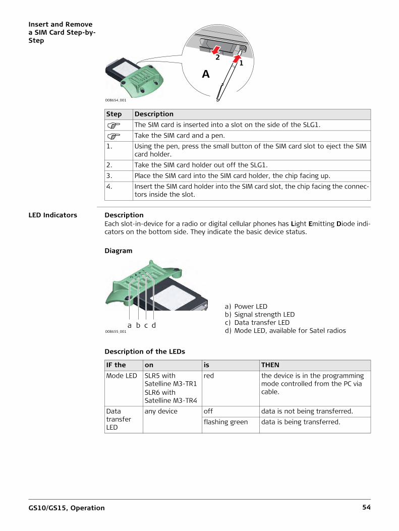
Insert and Remove a SIM Card Step-by-Step
LED Indicators DescriptionEach slot-in-device for a radio or digital cellular phones has Light Emitting Diode indi-cators on the bottom side. They indicate the basic device status.
Diagram
Description of the LEDs
Step Description
The SIM card is inserted into a slot on the side of the SLG1.
Take the SIM card and a pen.1. Using the pen, press the small button of the SIM card slot to eject the SIM
card holder.2. Take the SIM card holder out off the SLG1.3. Place the SIM card into the SIM card holder, the chip facing up.4. Insert the SIM card holder into the SIM card slot, the chip facing the connec-
tors inside the slot.
A1
2
008654_001
a) Power LEDb) Signal strength LEDc) Data transfer LEDd) Mode LED, available for Satel radios
IF the on is THENMode LED SLR5 with
Satelline M3-TR1SLR6 with Satelline M3-TR4
red the device is in the programming mode controlled from the PC via cable.
Data transfer LED
any device off data is not being transferred.flashing green data is being transferred.
008655_001a b c d

GS10/GS15, Operation 55
Signal strength LED
SLG1 with Telit UC864-G
red call is in progress.red: long flash, long break
no SIM card inserted, no PIN entered or network search, user authentication or network login in progress.
red: short flash, long break
logged on to network, no call in progress.
red: flashing red, long break
GPRS PDP context activated.
red: long flash, short break
Packet switched data transfer is in progress.
off device is off.SLR5 with Satelline M3-TR1SLR6 with Satelline M3-TR4
red the communication link, Data Carrier Detection, is okay on the roving instrument.
flashing red the communication link, Data Carrier Detection, is okay on the roving instrument, but signal is weak.
off the DCD is not okay.Power LED any device off power is off.
green power is okay.
IF the on is THEN

GS10/GS15, Operation 56
4.5 LED Indicators on GS10/GS15
LED indicators DescriptionThe GS10/GS15 GNSS instrument has Light Emitting Diode indicators. They indicate the basic instrument status.Diagram
Description of the LEDs
GS10 GS15
a) Bluetooth LEDb) Storage LEDc) Position LEDd) Power LEDse) RTK Base LEDf) RTK Rover LED
GS_092
a
bc
d
e f
GS_091GS_09GS_091
a c e fdb
IF the is THENBluetooth LED
green Bluetooth is in data mode and ready for connecting.
purple Bluetooth is connecting.blue Bluetooth has connected.
Storage LED off no SD card is inserted or GS10/GS15 is switched off.
green SD card is inserted but no raw data is being logged.
flashing green raw data is being logged.flashing yellow raw data is being logged but only 10% memory
left.flashing red raw data is being logged but only 5% memory
left.red SD card is full, no raw data is being logged.fast flashing red no SD card is inserted but GS10/GS15 is config-
ured to log raw data.Position LED off no satellites are tracked or GS10/GS15 is
switched off.flashing yellow less than four satellites are tracked, a position is
not yet available.yellow a navigated position is available.flashing green a code-only position is available.green a fixed RTK position is available.
SmartLink is converging or has converged.Power LED (active battery*1)
off battery is not connected, flat or GS10/GS15 is switched off.

GS10/GS15, Operation 57
*1 The battery, which currently powers the GS10/GS15 GNSS instrument.*2 Other batteries, which are inserted or connected but are not currently power the GS10/GS15 GNSS instrument.
4.6 Guidelines for Correct Results with GNSS Surveys
Undisturbed satel-lite signal reception
Successful GNSS surveys require undisturbed satellite signal reception, especially at the instrument which serves as a base. Set up the instrument in locations which are free of obstructions such as trees, buildings or mountains.
Steady instrument for static surveys
For static surveys, the instrument must be kept perfectly steady throughout the whole occupation of a point. Place the instrument on a tripod or pillar.
Centred and levelled instrument
Centre and level the instrument precisely over the marker.
green power is 40% - 100%.yellow power is 20% - 40%. The remaining time for
which enough power is available depends on the type of survey, the temperature and the age of the battery.
red power is 5% - 20%.fast flashing red power is low (<5%).
Power LED (passive battery*2)
off battery is not connected, flat or the GS10/GS15 is switched off.
flashing green power is 40% - 100%. LED is green for 1 s every 10 s.
flashing yellow power is 20% - 40%. LED is yellow for 1 s every 10 s.
flashing red power is less than 20%. LED is red for 1 s every 10 s.
RTK Rover LED
off GS10/GS15 is in RTK base mode or GS10/GS15 is switched off.
green GS10/GS15 is in rover mode. No RTK data is being received at the interface of the communication device.
flashing green GS10/GS15 is in rover mode. RTK data is being received at the interface of the communication device.
RTK Base LED off GS10/GS15 is in RTK rover mode or GS10/GS15 is switched off.
green GS10/GS15 is in RTK base mode. No RTK data is being passed to the RX/TX interface of the communication device.
flashing green GS10/GS15 is in RTK base mode. Data is being passed to the RX/TX interface of the communica-tion device.
IF the is THEN

GS10/GS15, Care and Transport 58
5 Care and Transport5.1 Transport
Transport in the field
When transporting the equipment in the field, always make sure that you• either carry the product in its original transport container,• or carry the tripod with its legs splayed across your shoulder, keeping the attached
product upright.
Transport in a road vehicle
Never carry the product loose in a road vehicle, as it can be affected by shock and vibration. Always carry the product in its transport container, original packaging or equivalent and secure it.
Shipping When transporting the product by rail, air or sea, always use the complete original Leica Geosystems packaging, transport container and cardboard box, or its equivalent, to protect against shock and vibration.
Shipping, transport of batteries
When transporting or shipping batteries, the person responsible for the product must ensure that the applicable national and international rules and regulations are observed. Before transportation or shipping, contact your local passenger or freight transport company.
5.2 Storage
Product Respect the temperature limits when storing the equipment, particularly in summer if the equipment is inside a vehicle. Refer to "6 Technical Data" for information about temperature limits.
Li-Ion batteries • Refer to "Technical Data" for information about storage temperature range.• Remove batteries from the product and the charger before storing.• After storage recharge batteries before using.• Protect batteries from damp and wetness. Wet or damp batteries must be dried
before storing or use.• A storage temperature range of 0°C to +30°C / +32°F to +86°F in a dry environment
is recommended to minimize self-discharging of the battery.• At the recommended storage temperature range, batteries containing a 40% to
50% charge can be stored for up to one year. After this storage period the batteries must be recharged.

GS10/GS15, Care and Transport 59
5.3 Cleaning and Drying
Product and accessories
• Use only a clean, soft, lint-free cloth for cleaning. If necessary, moisten the cloth with water or pure alcohol. Do not use other liquids; these may attack the polymer components.
Damp products Dry the product, the transport container, the foam inserts and the accessories at a temperature not greater than 40 °C [104 °F] and clean them. Remove the battery cover and dry the battery compartment. Do not repack until everything is dry. Always close the transport container when using in the field.
Cables and plugs Keep plugs clean and dry. Blow away any dirt lodged in the plugs of the connecting cables.
Connectors with dust caps
Wet connectors must be dry before attaching the dust cap.

GS10/GS15, Technical Data 60
6 Technical Data6.1 GS10/GS15 Technical Data6.1.1 Tracking Characteristics
Satellite reception Multi-frequency
Instrument channels Depending on the satellite systems and signals configured, a maximum number
of 555 channels is allocated.
Supported signals
Carrier phase and code measurements on L1, L2 and L5 (GPS) are fully independent with AS on or off.
Support of QZSS L1, L2S, L5Q, L6L and IRNSS L5A is incorporated and will be provided through future firmware upgrade.
6.1.2 Accuracy
Accuracy is dependent upon various factors including the number of satellites tracked, constellation geometry, observation time, ephemeris accuracy, ionospheric distur-bance, multipath and resolved ambiguities.
The following accuracies, given as root mean square, are based on measurements processed using Infinity and on real-time measurements.
The use of multiple GNSS systems can increase accuracy by up to 30% relative to GPS only.
Differential code The baseline precision of a differential code solution for static and kinematic surveys is 25 cm.
Differential phase in post-processing
Differential phase in real-time
System SignalGPS L1 C/A, L2P, L2C, L5GLONASS L1 C/A, L2P, L2CGalileo E1, E5a, E5b, AltBOCBeiDou B1, B2
Type Horizontal VerticalStatic and rapid static 3 mm + 0.5 ppm 5 mm + 0.5 ppmKinematic 8 mm + 1 ppm 15 mm + 1 ppmStatic with long observations 3 mm + 0.1 ppm 3.5 mm + 0.4 ppm
Type Horizontal VerticalSingle Baseline (<30 km) 8 mm + 1 ppm 15 mm + 1 ppmNetwork RTK 8 mm + 0.5 ppm 15 mm + 0.5 ppm

GS10/GS15, Technical Data 61
6.1.3 Technical Data
Dimensions The dimensions are given for the housing without the sockets.
Weight Instrument weights without battery and radio:
Recording Data (Leica GNSS raw data and RINEX data) can be recorded on the SD card.1 GB is sufficient for over 1 year of raw data logging based on logging every 15 s from an average of 15 satellites.
Power
Internal battery
External battery
Operating times The given operating times are valid for• GS10: instrument plus antenna; two fully charged GEB222 batteries.• GS15: instrument; two fully charged GEB212 batteries.• room temperature. Operating times will be shorter when working in cold weather.
Type Length [m] Width [m] Thickness [m]GS10 0.212 0.166 0.079
Type Height [m] Diameter [m]GS15 0.198 0.196
Type Weight [kg]/[lbs]GS10 1.20/2.65GS15 1.34/2.95
Power consumption: GS10/GS15, radio excluded: 3.5 W typically, 300 mAExternal supply voltage: Nominal 12 V DC ( , GEV71 car battery cable to a 12 V
car battery), voltage range 10.5 V-28 V DC
Type: Li-IonVoltage: 7.4 VCapacity: GEB212: 2.6 Ah
GEB222: 6.0 Ah
GEB371Type: Li-IonVoltage: 13 VCapacity: 16.8 Ah
Equipment Operating timeType Radio Digital cellular phoneStatic (GS10) - - 27 h continuouslyStatic (GS15) - - 19 h continuouslyRover (GS10) SATELLINE M3-TR1,
receive (GFU27)- 20 h continuously
SATELLINE M3-TR4, receive (GFU30)
- 20 h continuously
Rover (GS15) SATELLINE M3-TR1, receive (SLR5)
- 10 h continuously
SATELLINE M3-TR4, receive (SLR6)
- 10 h continuously

GS10/GS15, Technical Data 62
Electrical data
Galileo AltBOC covers bandwidth of Galileo E5a and E5b.
Environmental specifications
Temperature
Protection against water, dust and sand
Humidity
Rover (GS10) - Telit UC864-G (GFU28) 19 h continuouslyCinterion PXS8 (GFU29)
Rover (GS15) - Telit UC864-G (SLG1) 7.5 h continuously
Equipment Operating timeType Radio Digital cellular phone
Type GS10 GS15Voltage - -Current - -FrequencyGPS L1 1575.42 MHz
GPS L2 1227.60 MHz
GPS L5 1176.45 MHz
GLONASS L1 1602.5625-1611.5 MHz
GLONASS L2 1246.4375-1254.3 MHz
Galileo E1 1575.42 MHz
Galileo E5a 1176.45 MHz
Galileo E5b 1207.14 MHz
Galileo AltBOC 1191.795 MHz
BeiDou B1 1561.098 MHz
BeiDou B2 1207.14 MHz
Gain (LNA) Typically 22 dB Typically 22 dBNoise Figure Typically < 2 dB Typically < 2 dB
Type Operating temperature [°C] Storage temperature [°C]All instruments -40 to +65 -40 to +80Leica SD cards -40 to +80 -40 to +80Battery internal -20 to +55 -40 to +70
Type ProtectionAll instruments IP68 (IEC 60529)
Dust tightProtected against continuous immersion in waterTested for 2 h in 1.40 m depth
Type ProtectionAll instruments Up to 100 %
The effects of condensation are to be effectively counteracted by periodically drying out the instrument.

GS10/GS15, Technical Data 63
6.2 Antennas Technical Data
Description and use The antenna is selected for use based upon the application. The table gives a descrip-tion and the intended use of the individual antennas.
Dimensions
Connector
Mounting
Weight
Type Description UseAS05 GPS, GLONASS, SBAS single-
frequency antenna with built-in ground plane.
With GS06 or GS10/GS25.
AS10 GPS, GLONASS, Galileo, BeiDou, SBAS, QZSS, L-band antenna with built-in ground plane.
With GS10/GS25.
AR10 GPS, GLONASS, Galileo, BeiDou, SBAS, QZSS, L-band antenna with large ground plane and built-in radome.
With GS10/GS25 where higher precision is required.For example static surveys of long baselines, tectonic plate moni-toring and base stations.
AR20 GPS, GLONASS, Galileo, BeiDou, SBAS, QZSS, L-band antenna with gold choke ring ground plane. Optional protective radome.
High end applications, including all reference station and monitoring.Especially suited for Network RTK, where excellent multipath rejection and the best phase centre stability is required.
AR25 Dorne & Margolin GPS, GLONASS, Galileo, BeiDou, SBAS, QZSS, L-band antenna with 3D choke ring ground plane. Optional protective radome.
With GS10/GS25 where higher precision is required.For example static surveys of long baselines, tectonic plate moni-toring and base stations.
Type AS05/AS10 AR10 AR20 AR25Height 6.2 cm 14.0 cm 16.3 cm 20.0 cmDiameter 17.0 cm 24.0 cm 32.0 cm 38.0 cm
AS05/AS10/AR10: TNC femaleAR20/AR25: N female
All antennas: 5/8" Whitworth
AS05/AS10: 0.4 kgAR10: 1.1 kgAR20: 5.9 kgAR25: 7.6 kg, radome 1.1 kg

GS10/GS15, Technical Data 64
Electrical data
Galileo AltBOC covers bandwidth of Galileo E5a and E5b.
Type AS05 AS10 AR10 AR20 AR25Voltage 4.5 V to
18 V DC4.5 V to 18 V DC
3.3 V to 12 V DC
3.3 V to 12 V DC
3.3 V to 12 V DC
Current 35 mA typ. 35 mA typ. 100 mA max 100 mA max 100 mA maxFrequencyGPS L1 1575.42 MHz
GPS L2 1227.60 MHz
-
GPS L5 1176.45 MHz
-
GLONASS L1 1602.5625-1611.5 MHz
GLONASS L2 1246.4375-1254.3 MHz
-
GLONASS L3 - -
GLONASS L5 - - - -Galileo E1 1575.42 MHz
-
Galileo E5a 1176.45 MHz
-
Galileo E5b 1207.14 MHz
-
Galileo AltBOC 1191.795 MHz
-
Galileo E6 1278.75 MHz
- -
BeiDou B1 1561.098 MHz
BeiDou B2 1207.14 MHz
-
BeiDou B3 1268.52 MHz
- -
Gain (typically) 27 dBi 29 dBi 29 dBi 29 dBi 40 dBiNoise Figure (typically)
< 2 dBi < 2 dBi < 2 dBi < 2 dBi < 1.2 dBi max

GS10/GS15, Technical Data 65
Environmental specifications
Temperature
Protection against water, dust and sand
Humidity
Cable length
Type Operating temperature [°C] Storage temperature [°C]AS05/AS10/AR10 -40 to +70 -55 to +85AR20/AR25 -55 to +85 -55 to +90
Type ProtectionAS05/AS10 IP68 (IEC 60529)
Dust tightProtected against water jetsProtected against continuous immersion in waterTested for 2 h in 1.40 m depth
AR10/AR20/AR25 IP67 (IEC 60529)Dust tightProtected against water jetsWaterproof to 1 m temporary immersion
Type ProtectionAll antennas Up to 100 %
The effects of condensation are to be effectively counter-acted by periodically drying out the antenna.
Separation distance from instrument ...
to antenna Supplied cable lengths [m]
Optional cable lengths [m]
GS10/GS25 AS05/AS10/AR10/AR20/AR25
1.22.810
305070

GS10/GS15, Technical Data 66
6.3 Conformity to National Regulations
Conformity to National Regulations
For products which do not fall under R&TTE directive:
6.3.1 GS10
Conformity to national regulations
Frequency band
Output power
Antenna
Hereby, Leica Geosystems AG, declares that the product/s is/are in compliance with the essential requirements and other relevant provisions of the applicable European Directives. The declaration of conformity can be consulted at http://www.leica-geosystems.com/ce.
• Japanese Radio Law and Japanese Telecommunications Business Law Compliance.– This device is granted pursuant to the Japanese Radio Law and the Japanese
Telecommunications Business Law.– This device should not be modified (otherwise the granted designation number
will become invalid).
• FCC Part 15, 22 and 24 (applicable in US)• Hereby, Leica Geosystems AG, declares that the product GS10 is in compliance with
the essential requirements and other relevant provisions of Directive 1999/5/EC. The declaration of conformity can be consulted at http://www.leica-geosystems.com/ce.
Class 1 equipment according European Directive 1999/5/EC (R&TTE) can be placed on the market and be put into service without restric-tions in any EEA member state.
• The conformity for countries with other national regulations not covered by the FCC part 15, 22 and 24 or European directive 1999/5/EC has to be approved prior to use and operation.
• Japanese Radio Law and Japanese Telecommunications Business Law Compliance (applicable for Japan).– This device is granted pursuant to the Japanese Radio Law and the Japanese
Telecommunications Business Law.– This device should not be modified (otherwise the granted designation number
will become invalid).
Type Frequency band [MHz]GS10 1176.45
1191.7951207.141227.601246.4375 - 1254.31575.421602.4375 - 1611.5
Bluetooth 2402 - 2480
Type Output power [mW]GNSS Receive onlyBluetooth 5 (Class 1)
Type Antenna Gain [dBi] Connector Frequency band [MHz]
GNSS External GNSS antenna element (receive only)
- - -
Bluetooth Internal Microstrip antenna 1.5 - -

GS10/GS15, Technical Data 67
6.3.2 GS15
Conformity to national regulations
Frequency band
Output power
Antenna
• FCC Part 15, 22 and 24 (applicable in US)• Hereby, Leica Geosystems AG, declares that the product GS15 is in compliance with
the essential requirements and other relevant provisions of Directive 1999/5/EC. The declaration of conformity can be consulted at http://www.leica-geosystems.com/ce.
Class 1 equipment according European Directive 1999/5/EC (R&TTE) can be placed on the market and be put into service without restric-tions in any EEA member state.
• The conformity for countries with other national regulations not covered by the FCC part 15, 22 and 24 or European directive 1999/5/EC has to be approved prior to use and operation.
• Japanese Radio Law and Japanese Telecommunications Business Law Compliance (applicable for Japan).– This device is granted pursuant to the Japanese Radio Law and the Japanese
Telecommunications Business Law.– This device should not be modified (otherwise the granted designation number
will become invalid).
Type Frequency band [MHz]GS15 1176.45
1191.7951207.141227.601246.4375 - 1254.31561.0981575.421602.4375 - 1611.5
Bluetooth 2402 - 2480
Type Output power [mW]GNSS Receive onlyBluetooth 5 (Class 1)
Type Antenna Gain [dBi] Connector Frequency band [MHz]
GNSS Internal GNSS antenna element (receive only)
- - -
Bluetooth Internal Microstrip antenna 1.5 - -

GS10/GS15, Technical Data 68
6.3.3 GFU27, SATEL Satelline M3-TR1
Conformity to national regulations
Frequency band 403 MHz - 470 MHz
Output power
Antenna
Specific Absorption Rate (SAR)
The product meets the limits for the maximum permissible exposure of the guide-lines and standards which are force in this respect. The product must be used with the recommended antenna. A separation distance of at least 20 centimetres should be kept between the antenna and the body of the user or nearby person within the intended application.
• FCC Part 15 and 90 (applicable in US)• Hereby, Leica Geosystems AG, declares that the product GFU27 is in compliance
with the essential requirements and other relevant provisions of Directive 1999/5/EC and other applicable European Directives. The declaration of conformity can be consulted at http://www.leica-geosystems.com/ce.
• This Class 2 equipment may be operated in: AT, BE, CY, CZ, DK, EE, FI, FR, DE, GR, HU, IE, IT, LV, LT, LU, MT, NL, PL, PT, SK, SI, ES, SE, GB, IS, LI, NO, CH, BG, RO and TR.
Class 2 equipment according European Directive 1999/5/EC (R&TTE) for which following EEA Member States apply restrictions on the placing on the market or on the putting into service or require authorisation for use:• Russia• Ukraine (max. 10 mW output power, 433.050 -
434.790 MHz)• Georgia• Serbia
• The conformity for countries with other national regulations not covered by the FCC part 15 and 90 or European directive 1999/5/EC has to be approved prior to use and operation.
• Japanese Radio Law and Japanese Telecommunications Business Law Compliance.– This device is granted pursuant to the Japanese Radio Law and the Japanese
Telecommunications Business Law.– This device should not be modified (otherwise the granted designation number
will become invalid).
GFU27: 0.5 W - 1.0 W
Type Internal GAT1 GAT2Frequency band [MHz] 400 - 470 400 - 435 435 - 470Type Internal Detachable /2
antennaDetachable /2 antenna
Connector - TNC TNC

GS10/GS15, Technical Data 69
6.3.4 GFU28, Telit UC864-G
Conformity to national regulations
Frequency band UMTS/HSDPA (WCDMA/FDD) 850 MHz/ 1900 MHz/ 2100 MHzQuad-Band EGSM 850 MHz/ 900 MHz/ 1800 MHz/ 1900 MHzGPRS multi-slot class 12EDGE multi-slot class 12
Output power
Antenna
Specific Absorption Rate (SAR)
The product meets the limits for the maximum permissible exposure of the guide-lines and standards which are force in this respect. The product must be used with the recommended antenna. A separation distance of at least 20 centimetres should be kept between the antenna and the body of the user or nearby person within the intended application.
• FCC Part 15, 22 and 24 (applicable in US)• Hereby, Leica Geosystems AG, declares that the GFU28 is in compliance with the
essential requirements and other relevant provisions of Directive 1999/5/EC and other applicable European Directives. The declaration of conformity may be consulted at http://www.leica-geosystems.com/ce.
Class 1 equipment according European Directive 1999/5/EC (R&TTE) can be placed on the market and be put into service without restric-tions in any EEA Member state.
• The conformity for countries with other national regulations not covered by the FCC part 15, 22 and 24 or European directive 1999/5/EC has to be approved prior to use and operation.
• Japanese Radio Law and Japanese Telecommunications Business Law Compliance.– This device is granted pursuant to the Japanese Radio Law and the Japanese
Telecommunications Business Law.– This device should not be modified (otherwise the granted designation number
will become invalid).
EGSM850/900: 2 WGSM1800/1900: 1 WUMTS2100: 0.25 WEDGE850/900: 0.5 WEDGE1800/1900: 0.4 W
Type GS15 Internal GAT3 GAT5 GAT18Frequency band [MHz]
824 - 894 /890 - 960 /1710 - 1880 /1850 - 1990 /1920 - 2170
890 - 960 /1710 - 1880 /1920 - 2170
824 - 894 /1850 - 1990
824 - 894 /890 - 960 /1710 - 1880 /1850 - 1990 /1920 - 2170
Type Internal Detachable /2 antenna
Detachable /2 antenna
Detachable /2 antenna
Connector - TNC TNC TNC

GS10/GS15, Technical Data 70
6.3.5 GFU29, Cinterion PXS8
Conformity to national regulations
Frequency band UMTS/HSPA (WCDMA/FDD) 800 MHz/ 850 MHz/ 900 MHz/ 1900 MHz/ 2100 MHz(E)GSM 850 MHz/ 900 MHz/ 1800 MHz/ 1900 MHzGPRS/EDGE multi-slot class 12
Output power
Antenna
Specific Absorption Rate (SAR)
The product meets the limits for the maximum permissible exposure of the guide-lines and standards which are force in this respect. The product must be used with the recommended antenna. A separation distance of at least 20 centimetres should be kept between the antenna and the body of the user or nearby person within the intended application.
• FCC Part 15, 22 and 24 (applicable in US)• Hereby, Leica Geosystems AG, declares that the GFU29 is in compliance with the
essential requirements and other relevant provisions of Directive 1999/5/EC and other applicable European Directives. The declaration of conformity may be consulted at http://www.leica-geosystems.com/ce.
Class 1 equipment according European Directive 1999/5/EC (R&TTE) can be placed on the market and be put into service without restric-tions in any EEA Member state.
• The conformity for countries with other national regulations not covered by the FCC part 15, 22 and 24 or European directive 1999/5/EC has to be approved prior to use and operation.
• Japanese Radio Law and Japanese Telecommunications Business Law Compliance.– This device is granted pursuant to the Japanese Radio Law and the Japanese
Telecommunications Business Law.– This device should not be modified (otherwise the granted designation number
will become invalid).
UMTS/HSPA: 0.25 WEGSM850/900: 2 W (EDGE: 0.5 W)GSM1800/1900: 1 W (EDGE: 0.4 W)
Type GAT3 GAT5 GAT18Frequency band [MHz] 890 - 960 /
1710 - 1880 /1920 - 2170
824 - 894 /1850 - 1990
824 - 894 /890 - 960 /1710 - 1880 /1850 - 1990 /1920 - 2170
Type Detachable /2 antenna
Detachable /2 antenna
Detachable /2 antenna
Connector TNC TNC TNC

GS10/GS15, Technical Data 71
6.3.6 GFU30, SATEL Satelline M3-TR4
Conformity to national regulations
Frequency band 403 MHz - 470 MHz
Output power
Antenna
Specific Absorption Rate (SAR)
The product meets the limits for the maximum permissible exposure of the guide-lines and standards which are force in this respect. The product must be used with the recommended antenna. A separation distance of at least 20 centimetres should be kept between the antenna and the body of the user or nearby person within the intended application.
• FCC Part 15 and 90 (applicable in US)• Hereby, Leica Geosystems AG, declares that the product GFU30 is in compliance
with the essential requirements and other relevant provisions of Directive 1999/5/EC and other applicable European Directives. The declaration of conformity can be consulted at http://www.leica-geosystems.com/ce.
• This Class 2 equipment may be operated in: AT, BE, CY, CZ, DK, EE, FI, FR, DE, GR, HU, IE, IT, LV, LT, LU, MT, NL, PL, PT, SK, SI, ES, SE, GB, IS, LI, NO, CH, BG, RO and TR.
Class 2 equipment according European Directive 1999/5/EC (R&TTE) for which following EEA Member States apply restrictions on the placing on the market or on the putting into service or require authorisation for use:• Russia• Ukraine (max. 10 mW output power, 433.050 -
434.790 MHz)• Georgia• Serbia
• The conformity for countries with other national regulations not covered by the FCC part 15 and 90 or European directive 1999/5/EC has to be approved prior to use and operation.
• Japanese Radio Law and Japanese Telecommunications Business Law Compliance.– This device is granted pursuant to the Japanese Radio Law and the Japanese
Telecommunications Business Law.– This device should not be modified (otherwise the granted designation number
will become invalid).
GFU30: 0.5 W - 1.0 W
Type Internal GAT1 GAT2Frequency band [MHz] 400 - 470 400 - 435 435 - 470Type Internal Detachable /2
antennaDetachable /2 antenna
Connector - TNC TNC

GS10/GS15, Technical Data 72
6.3.7 SLR5, SATEL SATELLINE M3-TR1
Conformity to National Regulations
Frequency band 403 MHz - 470 MHz
Output power
Antenna
Specific Absorption Rate (SAR)
The product meets the limits for the maximum permissible exposure of the guide-lines and standards which are force in this respect. The product must be used with the recommended antenna. A separation distance of at least 20 centimetres should be kept between the antenna and the body of the user or nearby person within the intended application.
• FCC Part 15 (applicable in US)• Hereby, Leica Geosystems AG, declares that the product SLR5 is in compliance with
the essential requirements and other relevant provisions of Directive 1999/5/EC and other applicable European Directives. The declaration of conformity can be consulted at http://www.leica-geosystems.com/ce.
• This Class 2 equipment may be operated in: AT, BE, CY, CZ, DK, EE, FI, FR, DE, GR, HU, IE, IT, LV, LT, LU, MT, NL, PL, PT, SK, SI, ES, SE, GB, IS, LI, NO, CH, BG, RO and TR.
Class 2 equipment according European Directive 1999/5/EC (R&TTE)
• The conformity for countries with other national regulations not covered by the FCC part 15 or European directive 1999/5/EC has to be approved prior to use and oper-ation.
• Japanese Radio Law and Japanese Telecommunications Business Law Compliance.– This device is granted pursuant to the Japanese Radio Law and the Japanese
Telecommunications Business Law.– This device should not be modified (otherwise the granted designation number
will become invalid).
SLR5: 0.5 W-1.0 W
Type Internal GAT1 GAT2Frequency band [MHz] 400 - 470 400 - 435 435 - 470Type Internal Detachable /2
antennaDetachable /2 antenna
Connector - TNC TNC

GS10/GS15, Technical Data 73
6.3.8 SLR6, SATEL SATELLINE M3-TR4
Conformity to National Regulations
Frequency band 403 MHz - 470 MHz
Output power
Antenna
Specific Absorption Rate (SAR)
The product meets the limits for the maximum permissible exposure of the guide-lines and standards which are force in this respect. The product must be used with the recommended antenna. A separation distance of at least 20 centimetres should be kept between the antenna and the body of the user or nearby person within the intended application.
• FCC Part 15 (applicable in US)• Hereby, Leica Geosystems AG, declares that the product SLR6 is in compliance with
the essential requirements and other relevant provisions of Directive 1999/5/EC and other applicable European Directives. The declaration of conformity can be consulted at http://www.leica-geosystems.com/ce.
• This Class 2 equipment may be operated in: AT, BE, CY, CZ, DK, EE, FI, FR, DE, GR, HU, IE, IT, LV, LT, LU, MT, NL, PL, PT, SK, SI, ES, SE, GB, IS, LI, NO, CH, BG, RO and TR.
Class 2 equipment according European Directive 1999/5/EC (R&TTE)
• The conformity for countries with other national regulations not covered by the FCC part 15 or European directive 1999/5/EC has to be approved prior to use and oper-ation.
• Japanese Radio Law and Japanese Telecommunications Business Law Compliance.– This device is granted pursuant to the Japanese Radio Law and the Japanese
Telecommunications Business Law.– This device should not be modified (otherwise the granted designation number
will become invalid).
SLR6: 0.5 W-1.0 W
Type Internal GAT1 GAT2Frequency band [MHz] 400 - 470 400 - 435 435 - 470Type Internal Detachable /2
antennaDetachable /2 antenna
Connector - TNC TNC

GS10/GS15, Technical Data 74
6.3.9 SLG1, Telit UC864-G
Conformity to national regulations
Frequency band UMTS/HSDPA (WCDMA/FDD) 850 MHz/ 1900 MHz/ 2100 MHzQuad-Band EGSM 850 MHz/ 900 MHz/ 1800 MHz/ 1900 MHzGPRS multi-slot class 12EDGE multi-slot class 12
Output power
Antenna
Specific Absorption Rate (SAR)
The product meets the limits for the maximum permissible exposure of the guide-lines and standards which are force in this respect. The product must be used with the recommended antenna. A separation distance of at least 20 centimetres should be kept between the antenna and the body of the user or nearby person within the intended application.
• FCC Part 15, 22 and 24 (applicable in US)• Hereby, Leica Geosystems AG, declares that the SLG1 is in compliance with the
essential requirements and other relevant provisions of Directive 1999/5/EC and other applicable European Directives. The declaration of conformity may be consulted at http://www.leica-geosystems.com/ce.
Class 1 equipment according European Directive 1999/5/EC (R&TTE) can be placed on the market and be put into service without restric-tions in any EEA Member state.
• The conformity for countries with other national regulations not covered by the FCC part 15, 22 and 24 or European directive 1999/5/EC has to be approved prior to use and operation.
• Japanese Radio Law and Japanese Telecommunications Business Law Compliance.– This device is granted pursuant to the Japanese Radio Law and the Japanese
Telecommunications Business Law.– This device should not be modified (otherwise the granted designation number
will become invalid).
EGSM850/900: 2 WGSM1800/1900: 1 WUMTS2100: 0.25 WEDGE850/900: 0.5 WEDGE1800/1900: 0.4 W
Type GS15 Internal GAT3 GAT5 GAT18Frequency band [MHz]
824 - 894 /890 - 960 /1710 - 1880 /1850 - 1990 /1920 - 2170
890 - 960 /1710 - 1880 /1920 - 2170
824 - 894 /1850 - 1990
824 - 894 /890 - 960 /1710 - 1880 /1850 - 1990 /1920 - 2170
Type Internal Detachable /2 antenna
Detachable /2 antenna
Detachable /2 antenna
Connector - TNC TNC TNC

GS10/GS15, Technical Data 75
6.3.10 Dangerous Goods Regulations
Dangerous Goods Regulations
The products of Leica Geosystems are powered by Lithium batteries.
Lithium batteries can be dangerous under certain conditions and can pose a safety hazard. In certain conditions, Lithium batteries can overheat and ignite.
When carrying or shipping your Leica product with Lithium batteries onboard a commercial aircraft, you must do so in accordance with the IATA Dangerous Goods Regulations.
Leica Geosystems has developed Guidelines on “How to carry Leica products” and “How to ship Leica products” with Lithium batteries. Before any transpor-tation of a Leica product, we ask you to consult these guidelines on our web page (http://www.leica-geosystems.com/dgr) to ensure that you are in accord-ance with the IATA Dangerous Goods Regulations and that the Leica products can be transported correctly.
Damaged or defective batteries are prohibited from being carried or trans-ported onboard any aircraft. Therefore, ensure that the condition of any battery is safe for transportation.

GS10/GS15, Software Licence Agreement 76
7 Software Licence Agreement
Software Licence Agreement
This product contains software that is preinstalled on the product, or that is supplied to you on a data carrier medium, or that can be downloaded by you online according to prior authorisation from Leica Geosystems. Such software is protected by copyright and other laws and its use is defined and regulated by the Leica Geosystems Software Licence Agreement, which covers aspects such as, but not limited to, Scope of the Licence, Warranty, Intellectual Property Rights, Limitation of Liability, Exclusion of other Assurances, Governing Law and Place of Jurisdiction. Please make sure, that at any time you fully comply with the terms and conditions of the Leica Geosystems Soft-ware Licence Agreement.
Such agreement is provided together with all products and can also be referred to and downloaded at the Leica Geosystems home page at http://www.leica-geosystems.com/swlicense or collected from your Leica Geosystems distributor.
You must not install or use the software unless you have read and accepted the terms and conditions of the Leica Geosystems Software Licence Agreement. Installation or use of the software or any part thereof, is deemed to be an acceptance of all the terms and conditions of such Licence Agreement. If you do not agree to all or some of the terms of such Licence Agreement, you must not download, install or use the software and you must return the unused software together with its accompanying documentation and the purchase receipt to the distributor from whom you purchased the product within ten (10) days of purchase to obtain a full refund of the purchase price.

GS10/GS15, Pin Assignments and Sockets 77
Appendix A Pin Assignments and SocketsA.1 GS10
Description Some applications require knowledge of the pin assignments for the GS10 ports. In this chapter, the pin assignments and sockets for the ports of the GS10 are explained.
Ports at the instrument front panel
Pin assignments for port P1
Pin assignments for port P2, and port P3
Pin assignments for port PWR
a) Port P3: Power out, data in/out or remote interface in/out. 8 pin LEMOb) Port PWR: Power in. 5 pin LEMOc) Port ANT: GNSS antenna ind) Port P1: Field controller in/out or remote interface in/out. 8 pin LEMOe) Port P2: Power out, data in/out or remote interface in/out. 8 pin LEMO
GS_093
a
b
c
d
e
17
68
543
2
PIN_001
Pin Signal Name Function Direction1 USB_D+ USB data line In or out2 USB_D- USB data line In or out3 GND Signal ground -4 RxD RS232, receive data In5 TxD RS232, transmit data Out6 ID Identification pin In or out7 PWR Power input, 10.5 V-28 V In8 TRM_ON/USB_ID RS232, general-purpose signal In or out
17
68
543
2
PIN_003
Pin Signal Name Function Direction1 RTS RS232, ready to send Out2 CTS RS232, clear to send In3 GND Signal ground -4 RxD RS232, receive data In5 TxD RS232, transmit data Out6 ID Identification pin In7 GPIO RS232, configurable function In or out8 +12 V 12 V power supply out Out
15
43
2
PIN_004
Pin Signal Name Function Direction1 PWR1 Power input, 11 V-28 V In2 ID1 Identification pin In3 GND Signal ground -4 PWR2 Power input, 11 V-28 V In5 ID2 Identification pin In

GS10/GS15, Pin Assignments and Sockets 78
A.2 GS15
Description Some applications require knowledge of the pin assignments for the GS15 ports.In this chapter, the pin assignments and sockets for the ports of the GS15 are explained.
Ports at the instrument under-side
Pin assignments for port P1
Pin assignments for port P2
a) QN-connectorb) Port 2c) Port 1 (USB and serial)d) Port 30012261_001261 001
ab
c
d
17
68
543
2
PIN_001
Pin Signal Name Function Direction1 USB_D+ USB data line In or out2 USB_D- USB data line In or out3 GND Signal ground -4 RxD RS232, receive data In5 TxD RS232, transmit data Out6 ID Identification pin In or out7 PWR Power input, 10.5 V-28 V In8 TRM_ON/USB_ID RS232, general-purpose signal In or out
17
68
543
2
PIN_003
Pin Signal Name Function Direction1 RTS RS232, ready to send Out2 CTS RS232, clear to send In3 GND Signal ground -4 RxD RS232, receive data In5 TxD RS232, transmit data Out6 ID Identification pin In7 GPIO RS232, configurable function In or out8 +12 V 12 V power supply out Out

GS10/GS15, Pin Assignments and Sockets 79
Pin assignments for port P3
PIN_005
1A1 A2
8 9 10 11 12 13 14 15
2 3 4 5 6 7
Pin Signal Name Function Direction1 PWR 4 V power supply in In2 Tx Transmit data In3 Rx Receive data Out4 GPO/DCD General-purpose out, carrier detect out Out5 RTS Request to send In6 CTS Clear to send Out7 GPI/CFG General-purpose in, config mode in In8 PWR 6 V power supply in In9 GPIO General-purpose signal In or out10 GND Signal and chassis ground -11 USB+ USB data line (+) In or out12 USB- USB data line (-) In or out13 GND Signal and chassis ground -14 ID Identification pin In or out15 GPIO General-purpose signal In or outA1 NC Not used -A2 RF1 Antenna port, radio to antenna -
Leica Geosystems AGHeinrich-Wild-StrasseCH-9435 HeerbruggSwitzerlandPhone +41 71 727 31 31www.leica-geosystems.com
772916-8.0.0enOriginal text Printed in Switzerland © 2016 Leica Geosystems AG, Heerbrugg, Switzerland