Embed Size (px)
Citation preview
SOEN 341 Software Process
Lecture Notes
Peter Grogono
January 2003
Department of Computer ScienceConcordia University
Montreal, Quebec
SOEN 341/4 S Winter 2000 i
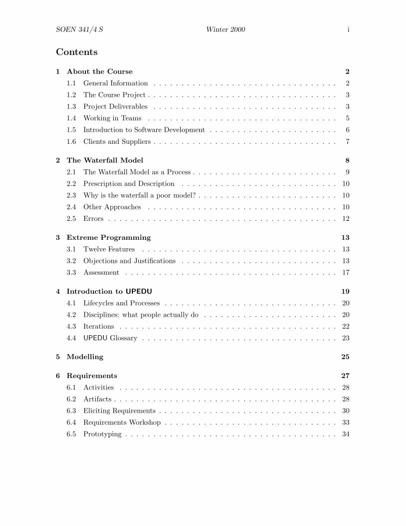
Contents
1 About the Course 2
1.1 General Information . . . . . . . . . . . . . . . . . . . . . . . . . . . . . . . . . 2
1.2 The Course Project . . . . . . . . . . . . . . . . . . . . . . . . . . . . . . . . . . 3
1.3 Project Deliverables . . . . . . . . . . . . . . . . . . . . . . . . . . . . . . . . . 3
1.4 Working in Teams . . . . . . . . . . . . . . . . . . . . . . . . . . . . . . . . . . 5
1.5 Introduction to Software Development . . . . . . . . . . . . . . . . . . . . . . . 6
1.6 Clients and Suppliers . . . . . . . . . . . . . . . . . . . . . . . . . . . . . . . . . 7
2 The Waterfall Model 8
2.1 The Waterfall Model as a Process . . . . . . . . . . . . . . . . . . . . . . . . . . 9
2.2 Prescription and Description . . . . . . . . . . . . . . . . . . . . . . . . . . . . 10
2.3 Why is the waterfall a poor model? . . . . . . . . . . . . . . . . . . . . . . . . . 10
2.4 Other Approaches . . . . . . . . . . . . . . . . . . . . . . . . . . . . . . . . . . 10
2.5 Errors . . . . . . . . . . . . . . . . . . . . . . . . . . . . . . . . . . . . . . . . . 12
3 Extreme Programming 13
3.1 Twelve Features . . . . . . . . . . . . . . . . . . . . . . . . . . . . . . . . . . . 13
3.2 Objections and Justifications . . . . . . . . . . . . . . . . . . . . . . . . . . . . 13
3.3 Assessment . . . . . . . . . . . . . . . . . . . . . . . . . . . . . . . . . . . . . . 17
4 Introduction to UPEDU 19
4.1 Lifecycles and Processes . . . . . . . . . . . . . . . . . . . . . . . . . . . . . . . 20
4.2 Disciplines: what people actually do . . . . . . . . . . . . . . . . . . . . . . . . 20
4.3 Iterations . . . . . . . . . . . . . . . . . . . . . . . . . . . . . . . . . . . . . . . 22
4.4 UPEDU Glossary . . . . . . . . . . . . . . . . . . . . . . . . . . . . . . . . . . . 23
5 Modelling 25
6 Requirements 27
6.1 Activities . . . . . . . . . . . . . . . . . . . . . . . . . . . . . . . . . . . . . . . 28
6.2 Artifacts . . . . . . . . . . . . . . . . . . . . . . . . . . . . . . . . . . . . . . . . 28
6.3 Eliciting Requirements . . . . . . . . . . . . . . . . . . . . . . . . . . . . . . . . 30
6.4 Requirements Workshop . . . . . . . . . . . . . . . . . . . . . . . . . . . . . . . 33
6.5 Prototyping . . . . . . . . . . . . . . . . . . . . . . . . . . . . . . . . . . . . . . 34
SOEN 341/4 S Winter 2000 ii
7 Design 35
7.1 Overview of Design . . . . . . . . . . . . . . . . . . . . . . . . . . . . . . . . . . 35
7.2 Remarks on Design . . . . . . . . . . . . . . . . . . . . . . . . . . . . . . . . . . 37
7.3 Varieties of Architecture . . . . . . . . . . . . . . . . . . . . . . . . . . . . . . . 37
7.4 Designing for Change . . . . . . . . . . . . . . . . . . . . . . . . . . . . . . . . . 40
7.5 Module Design . . . . . . . . . . . . . . . . . . . . . . . . . . . . . . . . . . . . 41
7.6 Design Notations . . . . . . . . . . . . . . . . . . . . . . . . . . . . . . . . . . . 43
7.7 Design Strategies . . . . . . . . . . . . . . . . . . . . . . . . . . . . . . . . . . . 43
7.8 Object Oriented Design . . . . . . . . . . . . . . . . . . . . . . . . . . . . . . . 46
7.9 Functional or Object Oriented? . . . . . . . . . . . . . . . . . . . . . . . . . . . 53
7.10 Writing MIS and IMD . . . . . . . . . . . . . . . . . . . . . . . . . . . . . . . . 54
8 Object Oriented Development 58
8.1 Analysis . . . . . . . . . . . . . . . . . . . . . . . . . . . . . . . . . . . . . . . . 59
8.2 Design . . . . . . . . . . . . . . . . . . . . . . . . . . . . . . . . . . . . . . . . . 64
8.3 Implementation . . . . . . . . . . . . . . . . . . . . . . . . . . . . . . . . . . . . 67
8.4 Reuse . . . . . . . . . . . . . . . . . . . . . . . . . . . . . . . . . . . . . . . . . 69
8.5 Other Process Models . . . . . . . . . . . . . . . . . . . . . . . . . . . . . . . . 70
8.6 Advantages and Disadvantages of Object Oriented Development . . . . . . . . 70
9 Implementation 72
9.1 The Implementation Discipline (UPEDU) . . . . . . . . . . . . . . . . . . . . . 72
9.2 Coding Conventions . . . . . . . . . . . . . . . . . . . . . . . . . . . . . . . . . 73
10 Testing 84
10.1 Coding Errors . . . . . . . . . . . . . . . . . . . . . . . . . . . . . . . . . . . . . 85
10.2 Fault Classification . . . . . . . . . . . . . . . . . . . . . . . . . . . . . . . . . . 86
10.3 Varieties of Testing . . . . . . . . . . . . . . . . . . . . . . . . . . . . . . . . . . 87
10.4 Testing Teams . . . . . . . . . . . . . . . . . . . . . . . . . . . . . . . . . . . . 88
10.5 Testing Components . . . . . . . . . . . . . . . . . . . . . . . . . . . . . . . . . 89
10.6 Integration Testing . . . . . . . . . . . . . . . . . . . . . . . . . . . . . . . . . . 91
10.7 Testing Object Oriented Code . . . . . . . . . . . . . . . . . . . . . . . . . . . . 92
10.8 Testing Strategies . . . . . . . . . . . . . . . . . . . . . . . . . . . . . . . . . . . 92
10.9 Avoid test failures: read your code . . . . . . . . . . . . . . . . . . . . . . . . . 93
10.10Project Requirements . . . . . . . . . . . . . . . . . . . . . . . . . . . . . . . . 94

SOEN 341/4 S Winter 2000 1
11 System Testing 95
11.1 Verification and Validation . . . . . . . . . . . . . . . . . . . . . . . . . . . . . 96
11.2 Unique Aspects of System Testing . . . . . . . . . . . . . . . . . . . . . . . . . 96
11.3 Reliability, Availability, Maintainability . . . . . . . . . . . . . . . . . . . . . . 97
11.4 Reliability during development . . . . . . . . . . . . . . . . . . . . . . . . . . . 99
11.5 Testing with UPEDU . . . . . . . . . . . . . . . . . . . . . . . . . . . . . . . . . 99
12 Delivery and Maintenance 102
12.1 Delivery . . . . . . . . . . . . . . . . . . . . . . . . . . . . . . . . . . . . . . . . 102
12.2 Maintenance . . . . . . . . . . . . . . . . . . . . . . . . . . . . . . . . . . . . . 102
13 Case Studies 107
13.1 The Therac-25 Saga . . . . . . . . . . . . . . . . . . . . . . . . . . . . . . . . . 107
13.2 The Ariane 5 Rocket Failure . . . . . . . . . . . . . . . . . . . . . . . . . . . . . 110
13.3 Case Study: RADARSAT Payload Computer Software System . . . . . . . . . 111
14 Industrial Practices 117
14.1 Measurement: COCOMO . . . . . . . . . . . . . . . . . . . . . . . . . . . . . . 117
14.2 Programming Languages and Notations . . . . . . . . . . . . . . . . . . . . . . 119
14.3 Theory and Practice . . . . . . . . . . . . . . . . . . . . . . . . . . . . . . . . . 121

SOEN 341/4 S Winter 2000 2
1 About the Course
1.1 General Information
1.1.1 Instructor
Name: Peter Grogono
Office: LB 927–17
Telephone: 848 3012
Email: [email protected]
Lectures: Wednesday and Friday, 1015–1130, H 535–2
Tutorial: Friday, 1315–1405, H 403
Office hours: Wednesday, 1145–1245, LB 927–17
Web page (course): http://www.cs.concordia.ca/~teaching/soen341
Web page (Sec S): http://www.cs.concordia/~faculty/grogono/SOEN341
Note that there are two web pages for the course: the first (in the table above) is for all threesections of the course and the second is for Section S only.
1.1.2 Background
The purpose of SOEN 341 is to introduce the basic concepts of industrial software developmentand to prepare you for subsequent software engineering courses such as: SOEN 342 SoftwareRequirements and Specifications ; SOEN 343 Software Design; SOEN 345 Software QualityControl ; and SOEN 383 Software Project Management.
You should have had some previous experience in programming, preferably object orientedprogramming using C++ or Java (COMP 249 or equivalent), some knowledge of data structuresand algorithms (COMP 352 or equivalent), and some knowledge of the principles of technicaldocumentation (SOEN 282 or equivalent).
1.1.3 Text Book
The recommended text for the course is:
• Software Engineering Process with the UPEDU. Pierre Robillard and Philippe Kruchten(with Patrick d’Astous). Addison Wesley (Pearson Education), 2003. ISBN 0–201–75454–1. http://www.yoopeedoo.org/index.asp.
1.1.4 Course Outline
The discipline of engineering. Introduction to Software Engineering. Software engineeringversus “programming”. Duties and responsibilities of a software engineer. Working as amember of a team; leading a team. Software life cycles and process models. RUP andUPEDU. From process to project; project management. Phases of the software process:
SOEN 341/4 S Winter 2000 3
requirements, specification, design, implementation, testing, delivery, and maintenance. Casestudies of software engineering practice.
1.1.5 Computing Facilities
You should use DCS Computing Laboratory H–929 which is equipped with PCs runningWindows.
1.1.6 Project
The major practical component of the course will be an object oriented program designed andimplemented by a team. Each team will consist of five or six students. We will discuss theroles of team members during classes. Each team will implement an application chosen froma list that will be provided by the instructor.
1.1.7 Evaluation
• You will be evaluated on the basis of quizzes (30%), assignments (20%), and a program-ming project (50%).
• You will do the quizzes and assignments individually and the project as a member of ateam.
• There will be four or five assignments. The assignments will be primarily theoretical,since the project provides the practical component. Late assignments will be discountedat 20% per day.
• There will be quizzes during the fourth, eighth, and twelfth weeks of the course. (Prob-able dates: Friday, 30 January; Friday, 6 March; and Friday, 4 April.)
1.2 The Course Project
The programming project contributes 50% of your marks for the course (see above).
Each project will be completed by a team of about 5 students. Instructors will divide studentsinto teams; the teams may make minor adjustments to their membership.
1.2.1 Schedule
Friday 10 January Instructor collects names
Wednesday 15 January Instructor proposes teams
Wednesday 22 January Teams submit names of team leader and team members
1.3 Project Deliverables
Each team must submit various deliverables as the project proceeds.
SOEN 341/4 S Winter 2000 4
Proposal. The proposal is a brief (one or two page) description of the project that theteam has decided to implement. Instructors will read the proposals carefully in order todecide whether they are appropriate for the course. They may suggest changes (either simpli-fications or extensions) of the proposed project or they may request a new proposal for a moreappropriate project. Since it is best to avoid writing two proposals, you should consult theinstructor before the due date if you have any doubts about the acceptability of your project.
Design. The design document consists of three components:
1. a general description of the software;
2. a high-level design showing the methods provided by each class and the interactionsbetween classes; and
3. a detailed design showing the attributes of each class and describing how each of itsmethods will be implemented.
Instructors will review the designs and give their opinions to the proposing team. The purposeof the design review is mainly to avoid a situation in which a team gets stuck trying toimplement an infeasible design.
Demonstration. Teams will demonstrate the programs they have written to the instructor.The purpose of the demonstration is to give the instructor an opportunity to see the programrunning, to try it out, and to discuss the project informally with the team. All team membersmust attend the demonstration.
Final Submission. To complete the project, each team must submit the following docu-ments:
1. A User Manual explaining how to operate the program from a user’s perspective.
2. Design Documentation , as described above, but possibly modified in the light ofexperience.
3. Implementation Notes describing particular features of the implementation, prob-lems encountered and how they were solved, etc.
4. Complete source code.
In addition, you must submit an individual report of your own experience in working on theproject: what you contributed, what was easy, what was hard, whether you had disagreements,etc.
For items 1 through 4 above, all members of a team will receive the same mark — up to 75%of the total marks for the project. Instructors will use the individual report to determine eachteam members’s contribution to the project — up to 25% of the total marks for the project.
SOEN 341/4 S Winter 2000 5
1.3.1 Choosing a Project
You have to design and implement a software application. The preferred programming lan-guages are C++ and Java.
The program can be quite ambitious (it is worth 5 students × 3 credits × 50% = 7.5 credits).The objective of the project, however, is a high quality software product : software that isuser-friendly, robust, and well-documented. Credit will be given for quality rather thanquantity.
1.4 Working in Teams
Why teams?
• Teams mean fewer projects and less work for me.
• Industrial programming is always done in teams.
• Employers want collaborators not stars.
• You can complete a larger project by working with others.
1.4.1 Roles of Team Members
One member of the team will be chosen by the team as its leader. The team leader actsas the communication channel between the instructor and the team. Apart from this, theresponsibilities of the team leader are the same as for other members of the team.
Each team decides how to allocate its resources. One possibility would be for all of themembers to collaborate in all of the tasks. At the other extreme, the team could allocateone person for design, one person for implementation, etc. In practice, something in betweenthese extremes is probably best. For example, two team members could take responsibilityfor the design, but they would also consult other team members during the design process.Keep in mind the project deliverables when assigning roles to team members.
It is the team’s responsibility to decide who should do what. There are two requirements:
• There must be a team leader . The team leader’s job is to interface between the teamand the instructor. Apart from this special role, the team leader performs the samework as other members of the team.
• The final submission must include an individual statement explaining what your personalrole in the team was.
Individual team members should have particular responsibilities. For example, one membercould be responsible for the design. Two or three members, or even the whole team, mightwork together on he design, but this person has the responsibility of ensuring that the designis completed by the deadline. The same goes for other aspects of the project:
• The proposal is a brief description of the project that the team intends to work on.
• The design is a detailed description of how the software is organized and how it willwork.

SOEN 341/4 S Winter 2000 6
• Implementing is the process of writing the code from the design.
• Testing is the process of checking that the code meets its specifications. (There are nodetailed specifications for this project, but it is still possible to test the program againstthe proposal and the design.)
• The project must be well documented .
Disputes. Arguments within teams are common. If possible, the team should resolve dis-agreements by itself. If this doesn’t work, the next step is to consult the tutor. If the tutorcannot solve the problem, the team leader should inform the instructor, who will probablyarrange to meet with the whole team.
Credit. Another potential problem with team work is that the instructor must give equalcredit to all team members. Team members may perceive this as unfair if some did morework than others. Problems of this kind should be solved by the team itself as far as possible.Individuals who feel that were treated unfairly should say so in their individual reports.
1.5 Introduction to Software Development
A process is a collection of organized activities that lead to a product .
In particular, a software process is a collection of organized activities that lead to a soft-ware product .
Software development is traditionally divided into various components, which we describebriefly here. For small projects, the components are developed in the order shown; for largerprojects, the components are interleaved or applied repetitively with gradually increasingrefinement. Large products are usually delivered as a sequence of increments rather than inone big lump.
1.5.1 Traditional Components
Requirements: The purpose of requirements analysis is to find out what the program isexpected to do. This is done in the application domain . The result of requirementsanalysis might be that we don’t need a program at all.
Specification: A specification is a precise description of what the program is supposed todo (but not how it works). The specification bridges the application domain and theimplementation domain because it describes the external behaviour of the computersystem. The specification can also be viewed as a contract between the client whowants the program and the software company that is supplying it.
Design: The design is a precise description of the internal structure of the program. Thedesign of an object oriented program is usually a description of the classes and theirinteractions.
Design is the most important, but also most difficult, phase of software development. Ifthe design is good, implementation should be straightforward. If the design is bad, theproject may fail altogether.

SOEN 341/4 S Winter 2000 7
Implementation: Implementation consists of writing the code: it is the activity that is oftencalled “programming”.
Testing: The code is tested thoroughly to ensure that the finished program meets its speci-fication.
Maintenance: The program is shipped to the client(s) but the supplier continues to correctand upgrade it.
It is easy to underestimate the cost and importance of maintenance. On average, for largesoftware projects, maintenance accounts for 80% of the total cost of the project.
1.6 Clients and Suppliers
Whenever software is produced, there is a client and a supplier . If the program is verysimple, the client and the supplier may be the same person. At the next level, an individualmight write a program for several people. At the largest scale, a company constructs softwarefor another company.
Whatever the size of the project, we will always use “client” to mean an entity that wantssomething and “supplier” to mean an entity that is prepared to create it.

SOEN 341/4 S Winter 2000 8
2 The Waterfall Model
The first software process to be formally proposed was the Waterfall Model . The waterfallmodel as usually presented includes the following phases, to be executed and completed inthe following order:
Requirements Analysis
System Design
Program Design
Coding
Unit and Integration Testing
System Testing
Acceptance Testing
Operation and Maintenance
The name “waterfall model” suggests that there is no going back: once a phase is completed,the documentation for that phase must not be altered.
An early modification to the original waterfall model was to allow feedback between consec-utive steps. For example, during coding, you could modify the program design but not thesystem design.
The waterfall as described here is not a good model: we will discuss its weaknesses later.
The following quotation is from a web discussion of the waterfall and other software processmodels (ff”http://c2.com/cgi/wiki?WaterFall):
The original waterfall model, as presented by Winston Royce in ManagingDevelopment of Large Scale Software Systems (Proceeding of IEEE WESCON,August 1970) actually made a lot of sense, and does not resemble at all what isportrayed as a Waterfall in the preceeding entries. What Royce said was that thereare two essential steps to develop a program: analysis and coding; but preciselybecause you need to manage all the intellectual freedom associated with softwaredevelopment, you must introduce several other “overhead” steps, which for a largeproject are:
• System requirements
• Software requirements
• Analysis
– Program design– Coding
∗ Testing∗ Operations
Many of Royce’s ideas would be considered obsolete today, but I don’t think theproblem lies so much with his model as with the cheap (not in terms of money, ofcourse) and rigoristic ways of misunderstanding what became an engineering and
SOEN 341/4 S Winter 2000 9
project management “standard”. This “standard” is what became “An AcceptableWay Of Failing”.
Royce’s valuable ideas must be understood before we simplistically discard theWaterfall. For example, when he advised to do some things twice he was postu-lating what we can call an embryonic form of iterative development. Also, somefeatures of the Waterfall are inevitable: as Alistair Cockburn has said elsewhere(http://members.aol.com/acockburn/papers/vwstage.htm) “how can you getto do testing if you have not coded?”.
The main problem has not been the Waterfall, but the schematicism involvedin a “standard box for all projects”. The variety of possible routes to follow isenormous: under many circumstances, training and empowering users to do theirown computing will be a radical alternative not only to analysis and design, but tocoding as well (after all, as Emiliano Zapata would have said, applications shouldbelong to those who make a living out of them). Under other circumstances,the best way to enhance team collaboration is to design the database through adiagram that makes the objects visible to all participants. — Jaime Gonzalez
2.1 The Waterfall Model as a Process
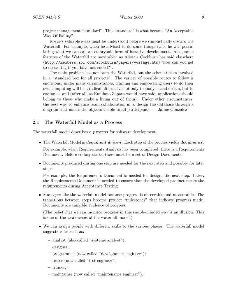
The waterfall model describes a process for software development.
• The Waterfall Model is document driven . Each step of the process yields documents .
For example, when Requirements Analysis has been completed, there is a RequirementsDocument. Before coding starts, there must be a set of Design Documents.
• Documents produced during one step are needed for the next step and possibly for latersteps.
For example, the Requirements Document is needed for design, the next step. Later,the Requirements Document is needed to ensure that the developed product meets therequirements during Acceptance Testing.
• Managers like the waterfall model because progress is observable and measurable. Thetransitions between steps become project “milestones” that indicate progress made.Documents are tangible evidence of progress.
(The belief that we can monitor progress in this simple-minded way is an illusion. Thisis one of the weaknesses of the waterfall model.)
• We can assign people with different skills to the various phases. The waterfall modelsuggests roles such as:
– analyst (also called “systems analyst”);
– designer;
– programmer (now called “development engineer”);
– tester (now called “test engineer”;
– trainer;
– maintainer (now called “maintenance engineer”).

SOEN 341/4 S Winter 2000 10
• We can estimate cost by adding the estimated costs of each phase and then adding asafety factor.
The problem is that we do not have enough information during the early phases to makeaccurate predictions about the effort needed, and hence the cost, of later phases.
Many software projects fail because of cost overruns. The suppliers estimate $3 millionand, when they have spent $6 million, the clients cancel the contract and expensive lawsuits follow.
2.2 Prescription and Description
There are two kinds of models.
• A prescriptive model describes what ought to be done (just as you get a “prescription”for medicine that you ought to take).
• A descriptive model describes what actually happens (as when the medicine makesyou feel even worse).
The waterfall model was introduced as a descriptive model: it was intended to describe whathappens in engineering projects and to use these observations for future projects.
The waterfall model became a prescriptive model: it proposes a method for software devel-opment that is hard to follow exactly and has several problems when it is followed exactly.
2.3 Why is the waterfall a poor model?
The waterfall model is based on engineering practice but it is not clear that experience gainedfrom construction of physical objects is going to work for software development.
The waterfall model is driven by documents. Documents may reflect what readers want tohear rather than what is actually happening. Slick documentation may cover up a projectthat is in turmoil.
Figure 1 compares and engineering activities, such as building a bridge, to constructing acomplex software product. The waterfall model works for bridges because bridge-building iswell-understood (although there are failures, usually when new designs are tried). The reasonthat it does not work for programming should be evident from the lists above: the softwaredevelopment process is not well-understood; scientific foundations are lacking; and softwarerequirements change.
Although the waterfall model in its original form does not work, the phases given aboveare nevertheless essential for any large software project . However, they should not beapplied one at a time in a particular order.
In the next section, we outline other possible approaches briefly. Then we illustrate the phasesin the context of a small application.
2.4 Other Approaches
Problems with the waterfall model have been recognized for a long time.

SOEN 341/4 S Winter 2000 11
Building a bridge Writing a program
the problem is well understood some problems are understood, others are not
sound scientific principles underly bridge de-sign
the scientific principles underlying softwareconstruction are still being developed
the strength and stability of a bridge can becalculated with reasonable precision
it is not feasible to calculate the correctnessof a complex program with methods that arecurrently available
the requirements for a bridge typically do notchange much during building
requirements typically change during allphases of development
there are many existing bridges although there are many existing programs,there are application areas in which only afew programs have been written
there are not all that many kinds of bridge there are very many different kinds of appli-cation
when a bridge collapses, there is a detailedinvestigation and report
when a program fails, the reasons are oftenunavailable or even deliberately concealed
engineers have been building bridges for thou-sands of years
programmers have been writing programs for50 years or so
materials (wood, stone, iron, steel) and tech-niques (making joints in wood, carving stone,casting iron, extruding steel) change slowly
hardware and software changes rapidly
Figure 1: A comparison of bridge building and programming
The emphasis in the waterfall model is on documents and writing . Fred Brooks (The Myth-ical Man Month , Anniversary Edition, 1995, page 200):
“I still remember the jolt I felt in 1958 when I first heard a friend talk aboutbuilding a program, as opposed to writing one.”
The “building” metaphor led to many new ideas: planning; specification as blueprint; compo-nents; assembly; scaffolding; etc. But the idea that planning preceded construction remained.
In 1971, Harlan Mills (IBM) proposed that we should grow software rather than build it.We begin by producing a very simple system that runs but has minimal functionality andthen add to it and let it grow. Ideally, the software grows like a flower or a tree; occasionally,however, it may spread like weeds.
The fancy name for growing software is incremental development . There are many varia-tions on this theme. The principal advantages of incremental development include:
• there is a working system at all times;
• clients can see the system and provide feedback;
• progress is visible, rather than being buried in documents;
SOEN 341/4 S Winter 2000 12
• some kinds of errors can be avoided.
Incremental development also has some disadvantages:
• design errors become part of the system and are hard to remove;
• clients see possibilities and want to change requirements.
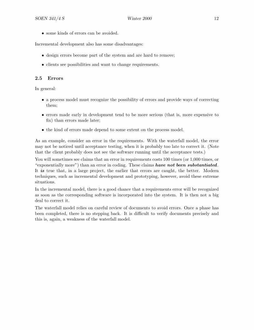
2.5 Errors
In general:
• a process model must recognize the possibility of errors and provide ways of correctingthem;
• errors made early in development tend to be more serious (that is, more expensive tofix) than errors made later;
• the kind of errors made depend to some extent on the process model.
As an example, consider an error in the requirements. With the waterfall model, the errormay not be noticed until acceptance testing, when it is probably too late to correct it. (Notethat the client probably does not see the software running until the acceptance tests.)
You will sometimes see claims that an error in requirements costs 100 times (or 1,000 times, or“exponentially more”) than an error in coding. These claims have not been substantiated .It is true that, in a large project, the earlier that errors are caught, the better. Moderntechniques, such as incremental development and prototyping, however, avoid these extremesituations.
In the incremental model, there is a good chance that a requirements error will be recognizedas soon as the corresponding software is incorporated into the system. It is then not a bigdeal to correct it.
The waterfall model relies on careful review of documents to avoid errors. Once a phase hasbeen completed, there is no stepping back. It is difficult to verify documents precisely andthis is, again, a weakness of the waterfall model.

SOEN 341/4 S Winter 2000 13
3 Extreme Programming
3.1 Twelve Features
Extreme Programming (XP) is a recent approach to software development introduced by KentBeck (Extreme Programming. Kent Beck. Addison Wesley 2000.) The twelve key features ofXP, outlined below in Beck’s words, are:
The Planning Game Quickly determine the scope of the next release by combining businesspriorities and technical estimates. As reality overtakes, update the plan.
Small Releases Put a simple system into production quickly, then release new versions ona very short cycle.
Metaphor Guide all development with a simple shared story of how the whole system works.
Simple Design The system should be designed as simply as possible at any given moment.Extra complexity is removed as soon as it is discovered.
Testing Programmers continually write unit tests, which must run flawlessly for developmentto continue. Customers write tests indicating theat features are finished.
Refactoring Programmers restructure the system without changing its behaviour to removeduplication, improve communication, simplify, or add flexibility.
Pair Programming All production code is written with two programmers at one worksta-tion.
Collective Ownership Anyone can change code anywhere in the system at any time.
Continuous Integration Integrate and build the system many times a day, every time atask is completed.
40-hour Week Work no more than 40 hours a week as a rule. Never allow overtime for thesecond week in a row.
On-site Customer include a real, live customer on the team, available full-time to answerquestions.
Coding Standards Programmers write all code in accordance with rules emphasizing com-munication throughout the code.
These ideas are not new. They have been tried before and there have been many reports offailure. The point of XP is that, taken together , these techniques do constitute a workablemethodology.
3.2 Objections and Justifications
We will consider each point in turn, explaining it briefly, pointing out its disadvantages, andthen showing how it works in the context of XP.
SOEN 341/4 S Winter 2000 14
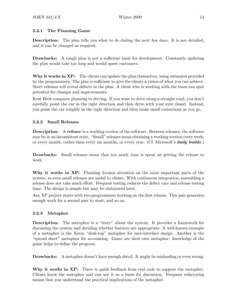
3.2.1 The Planning Game
Description: The plan tells you what to do during the next few days. It is not detailed,and it can be changed as required.
Drawbacks: A rough plan is not a sufficient basis for development. Constantly updatingthe plan would take too long and would upset customers.
Why it works in XP: The clients can update the plan themselves, using estimates providedby the programmers. The plan is sufficient to give the clients a vision of what you can achieve.Short releases will reveal defects in the plan. A client who is working with the team can spotpotential for changes and improvements.
Kent Beck compares planning to driving. If you want to drive along a straight road, you don’tcarefully point the car in the right direction and then drive with your eyes closed. Instead,you point the car roughly in the right direction and then make small corrections as you go.
3.2.2 Small Releases
Description: A release is a working version of the software. Between releases, the softwaremay be in an inconsistent state. “Small” releases mean obtaining a working version every week,or every month, rather than every six months, or every year. (Cf. Microsoft’s daily builds .)
Drawbacks: Small releases mean that too much time is spent on getting the release towork.
Why it works in XP: Planning focuses attention on the most important parts of thesystem, so even small releases are useful to clients. With continuous integration, assembling arelease does not take much effort. Frequent testing reduces the defect rate and release testingtime. The design is simple but may be elaborated later.
Any XP project starts with two programmers working on the first release. This pair generatesenough work for a second pair to start, and so on.
3.2.3 Metaphor
Description: The metaphor is a “story” about the system. It provides a framework fordiscussing the system and deciding whether features are appropriate. A well-known exampleof a metaphor is the Xerox “desk-top” metaphor for user-interface design. Another is the“spread sheet” metaphor for accounting. Game are their own metaphor: knowledge of thegame helps to define the program.
Drawbacks: A metaphor doesn’t have enough detail. It might be misleading or even wrong.
Why it works in XP: There is quick feedback from real code to support the metaphor.Clients know the metaphor and can use it as a basis for discussion. Frequent refactoringmeans that you understand the practical implications of the metaphor.
SOEN 341/4 S Winter 2000 15
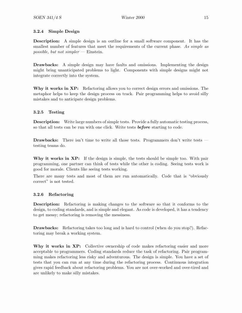
3.2.4 Simple Design
Description: A simple design is an outline for a small software component. It has thesmallest number of features that meet the requirements of the current phase. As simple aspossible, but not simpler — Einstein.
Drawbacks: A simple design may have faults and omissions. Implementing the designmight bring unanticipated problems to light. Components with simple designs might notintegrate correctly into the system.
Why it works in XP: Refactoring allows you to correct design errors and omissions. Themetaphor helps to keep the design process on track. Pair programming helps to avoid sillymistakes and to anticipate design problems.
3.2.5 Testing
Description: Write large numbers of simple tests. Provide a fully automatic testing process,so that all tests can be run with one click. Write tests before starting to code.
Drawbacks: There isn’t time to write all those tests. Programmers don’t write tests —testing teams do.
Why it works in XP: If the design is simple, the tests should be simple too. With pairprogramming, one partner can think of tests while the other is coding. Seeing tests work isgood for morale. Clients like seeing tests working.
There are many tests and most of them are run automatically. Code that is “obviouslycorrect” is not tested.
3.2.6 Refactoring
Description: Refactoring is making changes to the software so that it conforms to thedesign, to coding standards, and is simple and elegant. As code is developed, it has a tendencyto get messy; refactoring is removing the messiness.
Drawbacks: Refactoring takes too long and is hard to control (when do you stop?). Refac-toring may break a working system.
Why it works in XP: Collective ownership of code makes refactoring easier and moreacceptable to programmers. Coding standards reduce the task of refactoring. Pair program-ming makes refactoring less risky and adventurous. The design is simple. You have a set oftests that you can run at any time during the refactoring process. Continuous integrationgives rapid feedback about refactoring problems. You are not over-worked and over-tired andare unlikely to make silly mistakes.
SOEN 341/4 S Winter 2000 16
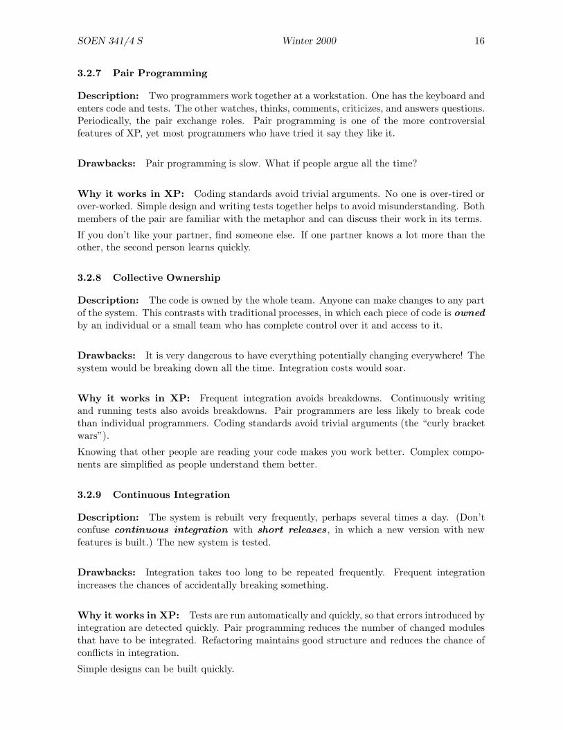
3.2.7 Pair Programming
Description: Two programmers work together at a workstation. One has the keyboard andenters code and tests. The other watches, thinks, comments, criticizes, and answers questions.Periodically, the pair exchange roles. Pair programming is one of the more controversialfeatures of XP, yet most programmers who have tried it say they like it.
Drawbacks: Pair programming is slow. What if people argue all the time?
Why it works in XP: Coding standards avoid trivial arguments. No one is over-tired orover-worked. Simple design and writing tests together helps to avoid misunderstanding. Bothmembers of the pair are familiar with the metaphor and can discuss their work in its terms.
If you don’t like your partner, find someone else. If one partner knows a lot more than theother, the second person learns quickly.
3.2.8 Collective Ownership
Description: The code is owned by the whole team. Anyone can make changes to any partof the system. This contrasts with traditional processes, in which each piece of code is ownedby an individual or a small team who has complete control over it and access to it.
Drawbacks: It is very dangerous to have everything potentially changing everywhere! Thesystem would be breaking down all the time. Integration costs would soar.
Why it works in XP: Frequent integration avoids breakdowns. Continuously writingand running tests also avoids breakdowns. Pair programmers are less likely to break codethan individual programmers. Coding standards avoid trivial arguments (the “curly bracketwars”).
Knowing that other people are reading your code makes you work better. Complex compo-nents are simplified as people understand them better.
3.2.9 Continuous Integration
Description: The system is rebuilt very frequently, perhaps several times a day. (Don’tconfuse continuous integration with short releases , in which a new version with newfeatures is built.) The new system is tested.
Drawbacks: Integration takes too long to be repeated frequently. Frequent integrationincreases the chances of accidentally breaking something.
Why it works in XP: Tests are run automatically and quickly, so that errors introduced byintegration are detected quickly. Pair programming reduces the number of changed modulesthat have to be integrated. Refactoring maintains good structure and reduces the chance ofconflicts in integration.
Simple designs can be built quickly.

SOEN 341/4 S Winter 2000 17
3.2.10 40-hour Week
Description: Many software companies require large amounts of overtime: programmerswork late in the evening and at weekends. They get over-tired, make silly mistakes. They getirritable, and waste time in petty arguments. The XP policy ensures that no one works toohard. Developers work no more than 40 hours in any one week. If they work overtime thisweek, they are not allowed to work overtime next week.
Drawbacks: 40 hours a week is not enough to obtain the productivity required for compet-itive software (at least, in the US!).
Why it works in XP: Good planning increases the value per hour of the work performed;there is less wasted time. Planning and testing reduces the frequency of unexpected surprises.XP as a whole helps you to work rapidly and efficiently.
3.2.11 On-site Customer
Description: A representative of the client’s company works at the developer’s site all thetime. (This may not be feasible if the client is very small, e.g., a one-person company.) Theclient is available all the time to consult with developers and monitor the development of thesoftware.
Drawbacks: The representative would be more valuable working at the client’s company.
Why it works in XP: Clients can contribute, e.g., by writing and commenting on tests.Rapid feedback for programmer questions is valuable.
3.2.12 Coding Standards
Description: All code written must follow defined conventions for layout, variable names,file structure, documentation, etc. Note that this is a local standard, not a standard definedby XP.
Drawbacks: Programmers are individualists and refuse to be told how to write their code.
Why it works in XP: The XP process makes them proud to be on a winning team.
3.3 Assessment
Kent Beck estimates there are between 500 and 1500 XP projects in progress now. Opponentsbelieve there are fewer: Craig Larman says that the only XP processes are those that Becksupervises.
The problem is that some groups pick a subset of the twelve features of XP and claim thatthey are “doing XP”, whereas Beck’s viewpoint is that XP consists of applying all twelvefeatures on a project.

SOEN 341/4 S Winter 2000 18
XP is an appropriate paradigm for small and medium projects. It has not been tried withteams of more than about 60 programmers and it is not clear that it would succeed at thisscale.
Nevertheless, XP contains a lot of good ideas and a lot of good psychology. XP assumes thatpeople are most productive if they are doing high-quality work and are not over-worked. XPrecognizes that documentation can be a liability rather than an asset.
SOEN 341/4 S Winter 2000 19
4 Introduction to UPEDU
During the 1980s, many approaches to software development were introduced. Some peopleproposed entire methodologies while others proposed components of a methodology. Theplayers included:
Grady Booch introduced object oriented design and modelling techniques;
Erich Gamma introduced design patterns;
David Harel introduced state charts for dynamic modelling;
Ivar Jacobson introduced use cases;
Bertrand Meyer defined programming by contract;
James Odell introduced classification concepts;
James Rumbaugh defined Object Modelling Technique (OMT);
Steven Shlaer and Stephen Mellor defined object lifecycles.
In the early stages, most of these people hyped their own ideas and put down other people’sideas. It gradually became clearer that they were all talking about pretty much the samething, and they began to combine their ideas rather than competing. Grady Booch foundedRational Software Corporation and several of the others joined it. Today, Rational claimsrevenues of about $500 million per year; 98% of the top (Fortune 100) companies use Rationaltools for software development.
Rational’s first significant product was the Unified Modelling Language (UML). UMLdefines a large number of symbols and diagrams that are used to model software and systemproducts. The basic idea is that a system cannot be represented by one diagram: manydiagrams are needed, and each diagram provides a diffferent view of the system. Since itwould be infeasible to maintain consistency of a large collection of diagrams, Rational provideComputer Aided Software Engineering (CASE) tools to draw and modify diagrams. Insome cases, it is possible to generate parts of the code automatically from diagrams.
Rational’s next product was the Rational Unified Process (RUP). RUP is a very generalmodel that can be specialized in many different ways. For example, both the Waterfall Model(WM) and Extreme Programming (XP) can be described using RUP, although it is unlikelythat a RUP developer would actually use either of them.
RUP is an iterative process that is intended for the incremental development of software.The phases of the WM (requirements, design, implementation, test, etc.) can be recognizedin RUP, but they may occur many times during development. For example, requirements maybe derived for each of many components instead of once only for the entire product.
UPEDU is a simplified version of RUP. “UPEDU” stands for Unified Process for Education.
UPEDU is based on development cycles . A project generally consists of several developmentcycles that may be performed sequentially or in an overlapping way (a new cycle begins beforeprevious cycles are complete).
UPEDU uses a number of words in a particular way. The following sections explain how thesewords are used; Section 4.4 provides brief definitions of each word.

SOEN 341/4 S Winter 2000 20
4.1 Lifecycles and Processes
A lifecycle is the entire history of a product. It begins with an idea for a product and endswhen the product ceases to exist. In between, there will many activities: determining therequirements, designing the product, constructing it, testing it, maintaining it, and so on.
A process is a discipline for moving a product through its lifecycle. There may be differentprocesses corresponding to a single lifecycle. For example, many buildings have a similarlifecycle: planning, foundation, walls, roof, finishing, demolition. However, the process ofcontructing the building depends on its size and function.
UPEDU consists of a collection of development cycles . The development cycles may besequential (that is, each cycle follows the next) but usually they are not: on a large project,several development cycles may be in progress concurrently.
A development cycle has four phases. The end of each phase is marked by a milestone . Thefour phases, and their milestones (in italics) are:
Inception: Create a justification for this phase; may involve requirements analysis, risk anal-ysis, prototyping. (Objective.)
Elaboration: Develop and analyze models for this phase; may involve development plans,user documentation, release description. (Architecture.)
Construction: Code the program or component and perform quality assurance. (OperationalCapability.)
Transition: Transfer the program or component to the user; ensure that the user has ade-quate documentation and other resources to make use of it. (Release.)
4.2 Disciplines: what people actually do
A software process should define: who does the work; what they do; when they do it; andhow they do it. A set of such definitions is a discipline . There are two main familiesof disciplines: engineering disciplines and management disciplines . The result ofcompleting a discipline is a model of the system. A model is one of several kinds of abstractand simplified representation of the system or one of its parts. In increasing level of detail,we may use a diagram, a description, and code to describe a software component.
Engineering Disciplines
Requirements Discipline: find out what the system is supposed to do and build a use-case model .
Analysis and Design Discipline: translate the requirements into a specification that de-scribes how to implement the system and build a design model .
Implementation Discipline: write and test the code for each component, giving an im-plementation model .
Test Discipline: assess the level of quality achieved and build a test model .
SOEN 341/4 S Winter 2000 21
Person Design Implement Test
Ann A C
Bill B
Chris A B
Diane B C
Eddie A C
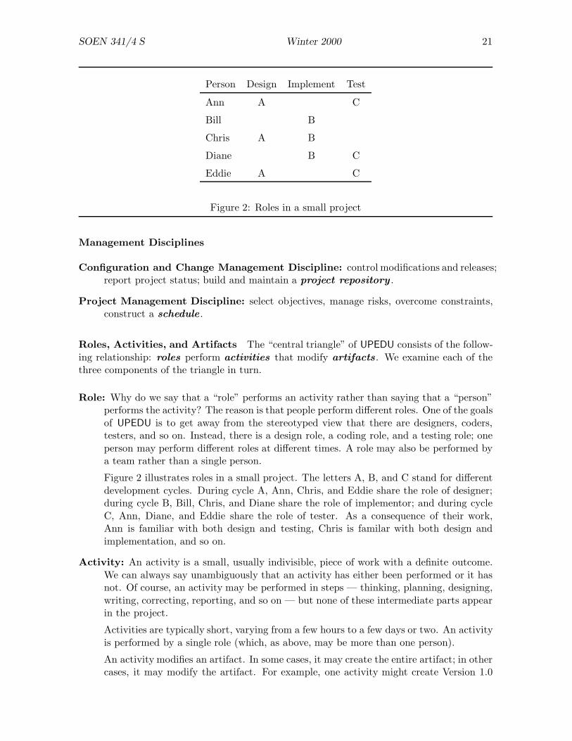
Figure 2: Roles in a small project
Management Disciplines
Configuration and Change Management Discipline: control modifications and releases;report project status; build and maintain a project repository .
Project Management Discipline: select objectives, manage risks, overcome constraints,construct a schedule .
Roles, Activities, and Artifacts The “central triangle” of UPEDU consists of the follow-ing relationship: roles perform activities that modify artifacts . We examine each of thethree components of the triangle in turn.
Role: Why do we say that a “role” performs an activity rather than saying that a “person”performs the activity? The reason is that people perform different roles. One of the goalsof UPEDU is to get away from the stereotyped view that there are designers, coders,testers, and so on. Instead, there is a design role, a coding role, and a testing role; oneperson may perform different roles at different times. A role may also be performed bya team rather than a single person.
Figure 2 illustrates roles in a small project. The letters A, B, and C stand for differentdevelopment cycles. During cycle A, Ann, Chris, and Eddie share the role of designer;during cycle B, Bill, Chris, and Diane share the role of implementor; and during cycleC, Ann, Diane, and Eddie share the role of tester. As a consequence of their work,Ann is familiar with both design and testing, Chris is familar with both design andimplementation, and so on.
Activity: An activity is a small, usually indivisible, piece of work with a definite outcome.We can always say unambiguously that an activity has either been performed or it hasnot. Of course, an activity may be performed in steps — thinking, planning, designing,writing, correcting, reporting, and so on — but none of these intermediate parts appearin the project.
Activities are typically short, varying from a few hours to a few days or two. An activityis performed by a single role (which, as above, may be more than one person).
An activity modifies an artifact. In some cases, it may create the entire artifact; in othercases, it may modify the artifact. For example, one activity might create Version 1.0

SOEN 341/4 S Winter 2000 22
of the design, and another activity might incorporate changes in the design leading toVersion 1.1.
Artifact: An artifact is a piece of information produced by completing an activity. Artifactsinclude reports, documents, files, models, diagrams, source code, executable code, andso on.
Artifacts are used as inputs as well as outputs. For example, the job of a coder is to usethe design (an artifact) to produce source code (another artifact).
4.3 Iterations
As we have already seen, software construction proceeds by iterating (or repeating) develop-ment cycles. Although each development cycle consists of the same four phases (inception,elaboration, construction, and transition), the relative weight of each discipline varies fromone cycle to another.
For example, the first development cycle will usually focus on gathering requirements. Latein the project, a development cycle would be more likely to focus on coding and testing.However, since almost all projects involve changing requirements, the requirements may haveto be considered in late cycles as well as early ones.
Consequently, software development should be seen as the application of all disciplines simul-taneously, but with different focuses depending on the state of the project.
The choice of development cycles, and the choice of activities within a development cycle,can be systematic or opportunistic. Realistically, this distinction should be viewed not aseither/or but rather a continuous spectrum of which we are defining the end points.
In systematic development , the developers have access to all of the information they needand iterations proceed in an orderly, planned way. The project schedule might predict theexpected work for several months ahead.
In opportunistic development , the developers do not have enough information to plan farahead. They might be expecting revised requirements, or waiting for the results of a timingtest. Under these circumstances, the choice of the next iteration may not be made until thetransition phase of the current iteration.
Entire projects may be systematically or opportunistically developed. In practice, however,it is more likely that the balance will change during the project. A new project might startopportunistically but, after a while, stabilize and become systematic. More frequently, aproject starts systematically and, when problems arise, drifts towards opportunism.
Opportunism does not matter provided that the project stays under control. The developmentcycle model is intended to help retain control of the project.
In the waterfall model, it may become clear during the implementation phase that the require-ments cannot be implemented as planned. This can lead to a panic mode of development inwhich programmers spend many hours of overtime trying to do impossible things. EdwardYourdon has a name for such projects (“death march”) and has written a book about them:Death March: The Complete Software Developer’s Guide to Surviving “Mission Impossible”Projects (Yourdon Computing Series).
SOEN 341/4 S Winter 2000 23
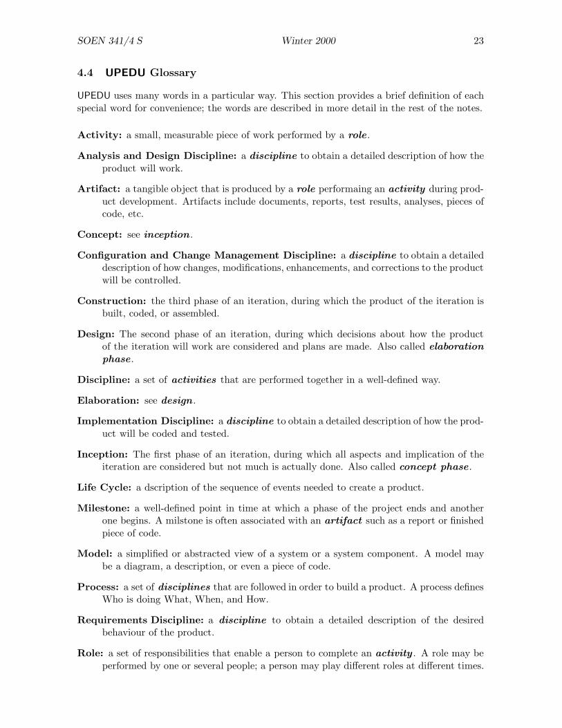
4.4 UPEDU Glossary
UPEDU uses many words in a particular way. This section provides a brief definition of eachspecial word for convenience; the words are described in more detail in the rest of the notes.
Activity: a small, measurable piece of work performed by a role .
Analysis and Design Discipline: a discipline to obtain a detailed description of how theproduct will work.
Artifact: a tangible object that is produced by a role performaing an activity during prod-uct development. Artifacts include documents, reports, test results, analyses, pieces ofcode, etc.
Concept: see inception .
Configuration and Change Management Discipline: a discipline to obtain a detaileddescription of how changes, modifications, enhancements, and corrections to the productwill be controlled.
Construction: the third phase of an iteration, during which the product of the iteration isbuilt, coded, or assembled.
Design: The second phase of an iteration, during which decisions about how the productof the iteration will work are considered and plans are made. Also called elaborationphase .
Discipline: a set of activities that are performed together in a well-defined way.
Elaboration: see design .
Implementation Discipline: a discipline to obtain a detailed description of how the prod-uct will be coded and tested.
Inception: The first phase of an iteration, during which all aspects and implication of theiteration are considered but not much is actually done. Also called concept phase .
Life Cycle: a dscription of the sequence of events needed to create a product.
Milestone: a well-defined point in time at which a phase of the project ends and anotherone begins. A milstone is often associated with an artifact such as a report or finishedpiece of code.
Model: a simplified or abstracted view of a system or a system component. A model maybe a diagram, a description, or even a piece of code.
Process: a set of disciplines that are followed in order to build a product. A process definesWho is doing What, When, and How.
Requirements Discipline: a discipline to obtain a detailed description of the desiredbehaviour of the product.
Role: a set of responsibilities that enable a person to complete an activity . A role may beperformed by one or several people; a person may play different roles at different times.

SOEN 341/4 S Winter 2000 24
Transition: the fourth and final phase of an iteration, during which the product of theiteration is assessed and tested (also called final phase). “Transition” emphasizes thatthis iteration will be linked to the next iteration.
SOEN 341/4 S Winter 2000 25
5 Modelling
Modelling is an important activity in Software Engineering. In this section, we look at therole played by modelling in various disciplines, and how modelling contributes to softwaredevelopment.
Who models? Amost any discipline in which complex artifacts are constructed makes useof modelling. Architects and designers of buildings, bridges, ships, cars, shopping centres,highways, and software all make use of models in one form or another.
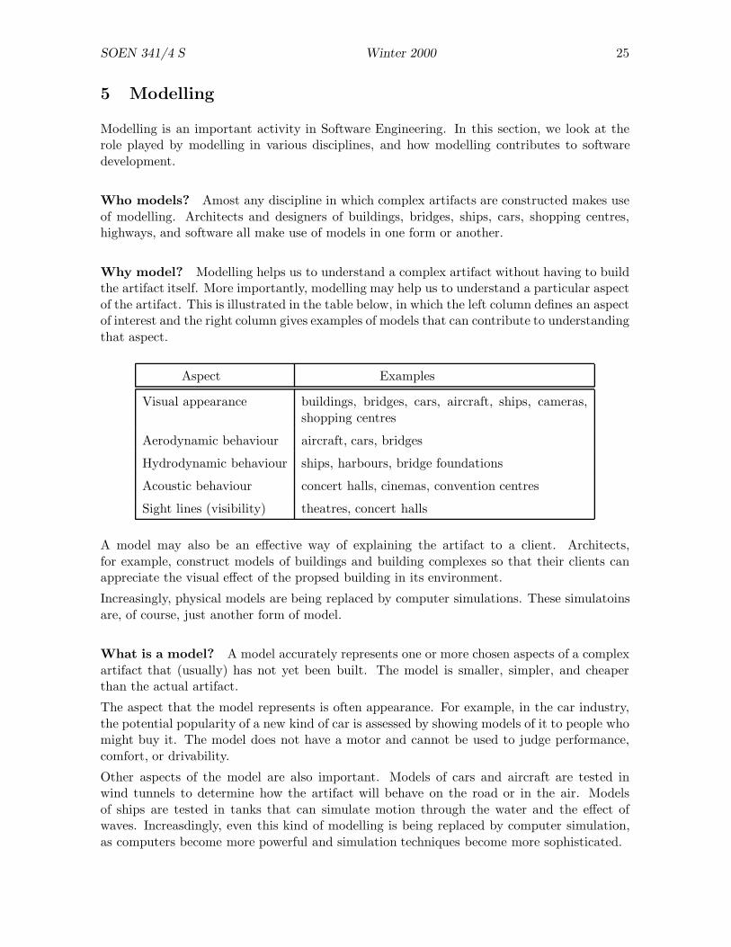
Why model? Modelling helps us to understand a complex artifact without having to buildthe artifact itself. More importantly, modelling may help us to understand a particular aspectof the artifact. This is illustrated in the table below, in which the left column defines an aspectof interest and the right column gives examples of models that can contribute to understandingthat aspect.
Aspect Examples
Visual appearance buildings, bridges, cars, aircraft, ships, cameras,shopping centres
Aerodynamic behaviour aircraft, cars, bridges
Hydrodynamic behaviour ships, harbours, bridge foundations
Acoustic behaviour concert halls, cinemas, convention centres
Sight lines (visibility) theatres, concert halls
A model may also be an effective way of explaining the artifact to a client. Architects,for example, construct models of buildings and building complexes so that their clients canappreciate the visual effect of the propsed building in its environment.
Increasingly, physical models are being replaced by computer simulations. These simulatoinsare, of course, just another form of model.
What is a model? A model accurately represents one or more chosen aspects of a complexartifact that (usually) has not yet been built. The model is smaller, simpler, and cheaperthan the actual artifact.
The aspect that the model represents is often appearance. For example, in the car industry,the potential popularity of a new kind of car is assessed by showing models of it to people whomight buy it. The model does not have a motor and cannot be used to judge performance,comfort, or drivability.
Other aspects of the model are also important. Models of cars and aircraft are tested inwind tunnels to determine how the artifact will behave on the road or in the air. Modelsof ships are tested in tanks that can simulate motion through the water and the effect ofwaves. Increasdingly, even this kind of modelling is being replaced by computer simulation,as computers become more powerful and simulation techniques become more sophisticated.

SOEN 341/4 S Winter 2000 26
A flight simulator is a particularly sophisticated form of model: it models the cockpit of anaircraft in gret detail, but nothing else. The behaviour of the model is close enough to thereal thing that pilots receive extensive training in simulators.
A diagram is a simple form of model. Electronic engineers draw diagrams of circuits (“schemat-ics”) and discuss and analyze them before constructing the actual circuit. Circuits are under-stood so well that the behaviour of the circuit is unlikely to differ much from the behavioourpredicted from the schematic.
Software is usually modelled with diagrams. There is a long history of diagramming in softwaredevelopment; many kinds of diagrams were used at one time but are now considered obsolete.The Universal Modeling Language (UML) is based on diagrams.
SOEN 341/4 S Winter 2000 27
6 Requirements
The requirements for a software project consist of a detailed description, written in non-technical language, of the capability that the completed system must have in order to satisfythe clients.
By “non-technical language” here, we mean language that does not use software- or computer-related terminology. The language may be “technical” in the client’s domain. For example,the requirements for a patient-monitoring system might contain medical jargon.
The requirements are written for the benefit of stakeholders of the system. A stakeholderis any person or group who will be affected by the system. Stakeholders include clients,suppliers, end users, project managers, software engineers, and perhaps others. For a FlightControl System, even the public might be considered a stakeholder, because everyone wantsassurance that flying is safe.
Specifically, requirements are written for:
Clients: to ensure that they get what they want or need.
Designers: to ensure that they design the system that is wanted.
Implementors: to ensure that coding details are correct.
Testers: to ensure that the system does what it is supposed to do.
Technical writers: to prepare user manuals and other documentation.
Trainers: to prepare procedures for training end users.
A set of requirements is often referred to as an SRS , short for Software Requirements Speci-fication.
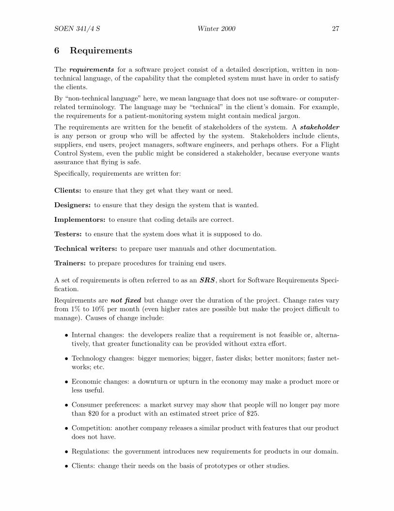
Requirements are not fixed but change over the duration of the project. Change rates varyfrom 1% to 10% per month (even higher rates are possible but make the project difficult tomanage). Causes of change include:
• Internal changes: the developers realize that a requirement is not feasible or, alterna-tively, that greater functionality can be provided without extra effort.
• Technology changes: bigger memories; bigger, faster disks; better monitors; faster net-works; etc.
• Economic changes: a downturn or upturn in the economy may make a product more orless useful.
• Consumer preferences: a market survey may show that people will no longer pay morethan $20 for a product with an estimated street price of $25.
• Competition: another company releases a similar product with features that our productdoes not have.
• Regulations: the government introduces new requirements for products in our domain.
• Clients: change their needs on the basis of prototypes or other studies.
SOEN 341/4 S Winter 2000 28
Building a large product on the basis of a fixed set of requirements is a recipe for disaster.The principal weakness of the Waterfall Model was its failure to accept that requirementschange during the development of a product.
6.1 Activities
In UPEDU, requirements consists of five activities . As usual, the terms “analysts” and“reviewers” refer to actors, not to people.
Understand the problem (analysts)
(1) elicit client needs
(2) identify actors and use cases
Define the system (analysts)
(3) structure use-case models
(4) detail use cases
Review (reviewers)
(5) review requirements
6.2 Artifacts
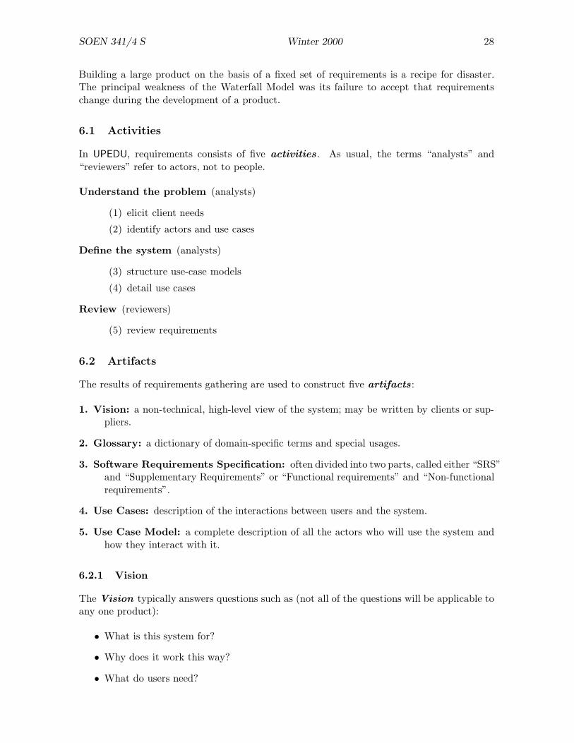
The results of requirements gathering are used to construct five artifacts :
1. Vision: a non-technical, high-level view of the system; may be written by clients or sup-pliers.
2. Glossary: a dictionary of domain-specific terms and special usages.
3. Software Requirements Specification: often divided into two parts, called either “SRS”and “Supplementary Requirements” or “Functional requirements” and “Non-functionalrequirements”.
4. Use Cases: description of the interactions between users and the system.
5. Use Case Model: a complete description of all the actors who will use the system andhow they interact with it.
6.2.1 Vision
The Vision typically answers questions such as (not all of the questions will be applicable toany one product):
• What is this system for?
• Why does it work this way?
• What do users need?
SOEN 341/4 S Winter 2000 29
• What are the goals and objectives of the system?
• What are the intended markets?
• What environment should users work in?
• What platforms are supported?
• What are the main features of the product?
6.2.2 Glossary
The Glossary ensures that everyone involved in the project agrees on the meaning of partic-ular words and phrases. It is important because many words are used in quite different waysin different disciplines. For example, “stroke” means one thing to a car mechanic and anotherto a cardiologist.
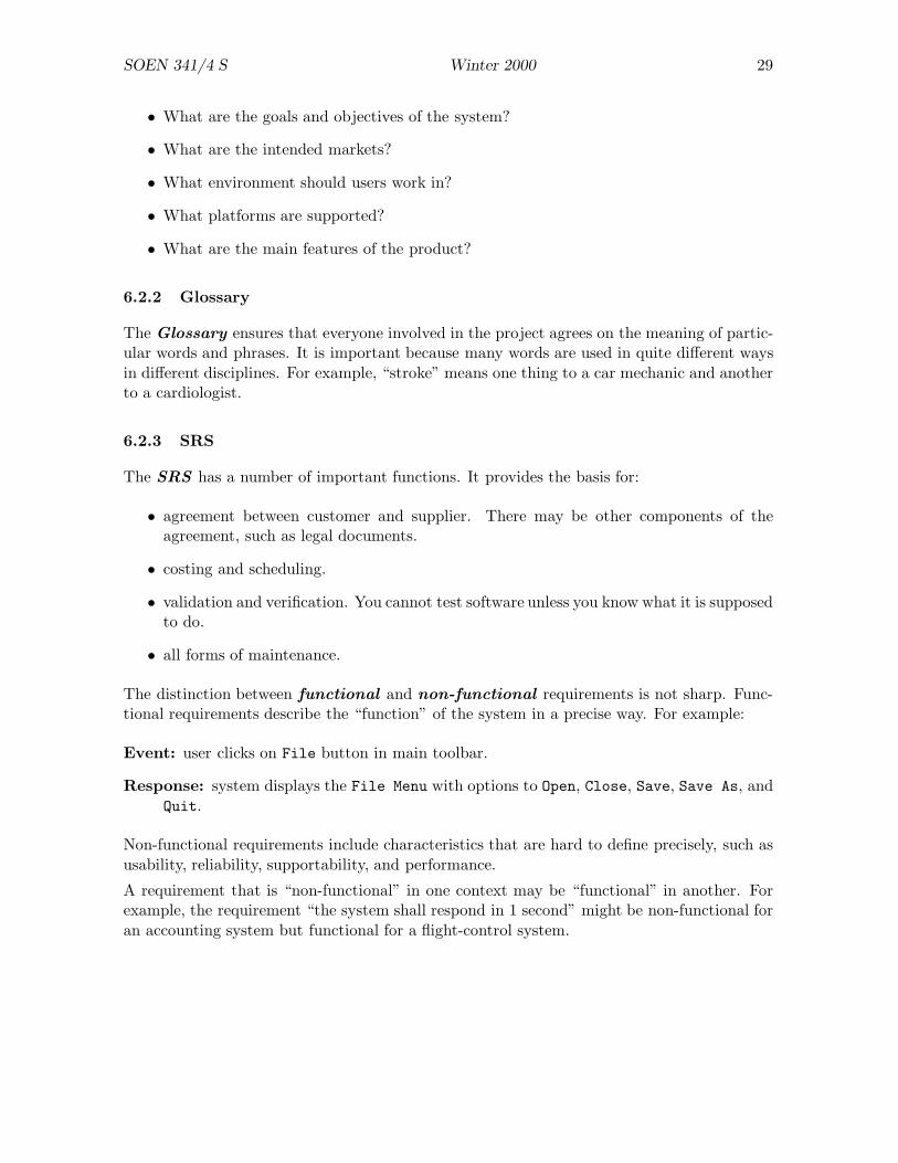
6.2.3 SRS
The SRS has a number of important functions. It provides the basis for:
• agreement between customer and supplier. There may be other components of theagreement, such as legal documents.
• costing and scheduling.
• validation and verification. You cannot test software unless you know what it is supposedto do.
• all forms of maintenance.
The distinction between functional and non-functional requirements is not sharp. Func-tional requirements describe the “function” of the system in a precise way. For example:
Event: user clicks on File button in main toolbar.
Response: system displays the File Menu with options to Open, Close, Save, Save As, andQuit.
Non-functional requirements include characteristics that are hard to define precisely, such asusability, reliability, supportability, and performance.
A requirement that is “non-functional” in one context may be “functional” in another. Forexample, the requirement “the system shall respond in 1 second” might be non-functional foran accounting system but functional for a flight-control system.

SOEN 341/4 S Winter 2000 30
6.2.4 Use Cases
Use cases describe interactions between the end users and the system.
• A use case describes a single interaction.
• A use case class describes a group of related use cases, often involving several actors.
• A scenario is an instance of a use case class.
• A use case model includes all of the use cases for the system.
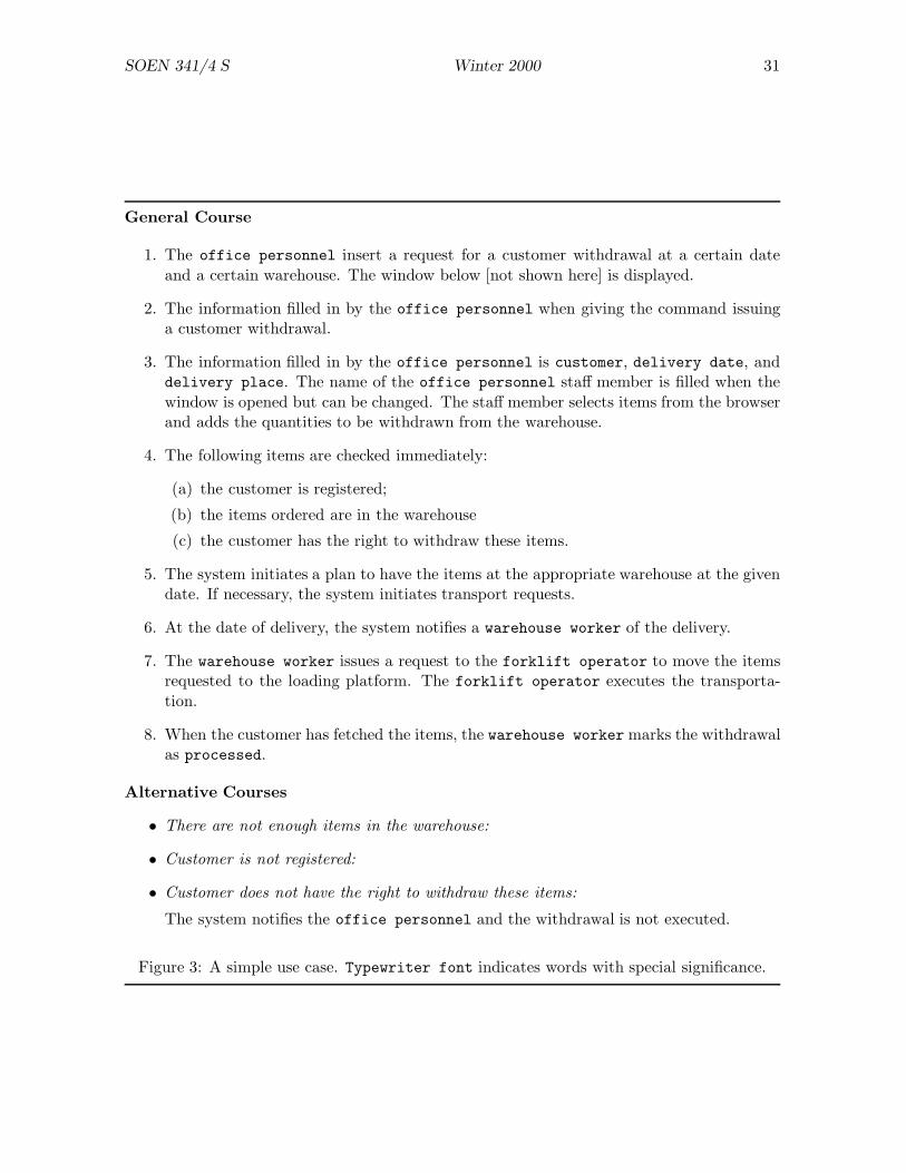
Figure 3 shows a simple use case (adapted from Object Oriented Software Engineering: a UseCase Driven Approach by Ivar Jacobson et al., pages 348–9).
6.3 Eliciting Requirements
Clients and suppliers work together during requirements gathering. The clients explain theirbusiness and the intended role of the software. The analysts observe, ask questions, andconduct formal interviews. There are three main aspects to focus on:
• the needs of the clients
• understanding the problem domain
• understanding the form of solution that is required
6.3.1 An Example
As an example, suppose that you are eliciting requirements for a grocery store that wishes toautomate its operations. Your activities might include:
• watching how the store operates
• interviewing people who work in different parts of the store (including areas inaccessibleto the public, such as store-rooms and accounting offices)
• estimating volumes required (how many customers are served, how many items do theybuy, how many suppliers deliver goods to the store, how frequent are the deliveries, etc.)
• determining the shelf-life of various kinds of goods (to determine re-order rates)
• determining the amount of stock held
6.3.2 Hints
Here are some hints for writing requirements.
• Include input/output specifications.
• Give representative, but possibly incomplete, examples.
SOEN 341/4 S Winter 2000 31
General Course
1. The office personnel insert a request for a customer withdrawal at a certain dateand a certain warehouse. The window below [not shown here] is displayed.
2. The information filled in by the office personnel when giving the command issuinga customer withdrawal.
3. The information filled in by the office personnel is customer, delivery date, anddelivery place. The name of the office personnel staff member is filled when thewindow is opened but can be changed. The staff member selects items from the browserand adds the quantities to be withdrawn from the warehouse.
4. The following items are checked immediately:
(a) the customer is registered;
(b) the items ordered are in the warehouse
(c) the customer has the right to withdraw these items.
5. The system initiates a plan to have the items at the appropriate warehouse at the givendate. If necessary, the system initiates transport requests.
6. At the date of delivery, the system notifies a warehouse worker of the delivery.
7. The warehouse worker issues a request to the forklift operator to move the itemsrequested to the loading platform. The forklift operator executes the transporta-tion.
8. When the customer has fetched the items, the warehouse worker marks the withdrawalas processed.
Alternative Courses
• There are not enough items in the warehouse:
• Customer is not registered:
• Customer does not have the right to withdraw these items:
The system notifies the office personnel and the withdrawal is not executed.
Figure 3: A simple use case. Typewriter font indicates words with special significance.

SOEN 341/4 S Winter 2000 32
• Use models: mathematical (e.g. regular expressions); functional (e.g. finite state ma-chines); timing (e.g. augmented FSM).
• Distinguish mandatory, desirable, and optional requirements.√
The user interface must use X Windows exclusively.√
The software must provide the specified performance when executed with 16Mb ofRAM. Preferably, it should be possible to execute the software with 8Mb of RAM.√
Sound effects are desirable but not required.
• Anticipate change. Distinguish what should not change, what may change, and whatwill probably change.√
The FSM diagram will contain at least nodes and arcs.√
The software may eventually be required to run on machines with the EBCDICcharacter set.
A well-written SRS will reduce development effort by avoiding (expensive) changes later, indesign and implementation phases. The following examples include both good usage (indicatedby
√) and bad usage (indicated by ×) (see also Robillard, page 85).
• The SRS should define all of the software requirements but no more. In particular,the SRS should not describe any design, verification, or project management details.
× The table is ordered for binary search.
× The table is organized for efficient search.√
The search must be completed in time O(logN).
• The SRS must be unambiguous.
– There should be exactly one interpretation of each sentence.– Special words should be defined. Some SRDs use a special notation for words used
in a specific way: !cursor!.– Avoid “variety” — good English style, but not good SRS style.– Careful usage.
× The checksum is read from the last record.Does “last” mean (a) at end of file, (b) most recently read, or (c) previous?√
. . . from the final record of the input file.√
. . . from the record most recently processed.
• The SRS must be complete. It must contain all of the significant requirements relatedto functionality (what the software does), performance (space/time requirements), de-sign constraints (“must run in 64Mb”), and external interfaces. The SRS must definethe response of the program to all inputs.
• The SRS must be verifiable. A requirement is verifiable if there is an effective procedurethat allows the product to be checked against the SRS.
× The program must not loop.
× The program must have a nice user interface.√
The response time must be less than 5 seconds for at least 90% of queries.

SOEN 341/4 S Winter 2000 33
• The SRS must be consistent. A requirement must not conflict with another require-ment.
× When the cursor is in the text area, it appears as an I-beam. . . . During a search,the cursor appears as an hour-glass.
• The SRS must be modifiable. It should be easy to revise requirements safely — withoutthe danger of introducing inconsistency. This requires:
– good organization;– table of contents, index, extensive cross-referencing;– minimal redundancy.
• The SRS must be traceable.
– The origin of each requirement must be clear. (Implicitly, a requirement comesfrom the client; other sources should be noted.)
– The SRS may refer to previous documents, perhaps generated during negotiationsbetween client and supplier .
– The SRS must have detailed numbering scheme.
• The SRS must be usable during the later phases of the project. It is not written to bethrown away! A good SRS should be of use to maintenance programmers.
The SRS is prepared by both the supplier with help and feedback from the client.
• The client (probably) does not understand software development.
• The supplier (probably) does not understand the application.
6.4 Requirements Workshop
A requirements workshop is an effective way of getting requirements quickly. It should bean intensive meeting in which many or all of the interested parties (stakeholders) get together.Features of a successful workshop include:
• Clients, end users, designers, programmers, testers, and others are all given a chanceto hear about the system and to comment on it. It is unlikely that there will beopportunities for this kind of interaction later in the development process.
• Results from the workshop should be quickly (or even immediately) available.
• Brainstorming may be productive: participators are encouraged to submit any ideas,however wild; some of the ideas may turn out to be useful, or to lead the discussion intofruitful areas.
• “Storyboarding” means outlining possible scenarios involving the system. The storiesmay draw attention to aspects that might otherwise have been neglected. Some storiesmay be developed into use cases.
• People who will be involved in the final system can act out their roles. Others cansimulate their roles.
• Existing requirements can be critically reviewed.
SOEN 341/4 S Winter 2000 34
6.5 Prototyping
Prototyping is an important technqiue that can be practiced at any part of the developmentcycle but is often viewed as a part of requirements elicitation.
A prototype is a piece of software (or, occasionally, hardware) that provides some of thefunctionality of the system.
• A UI prototype demonstrates how the user interface of the system will work but doesnot provide any functionality. Users can see what screens and windows will look like,can experiment with menu hierarchies, can look at presentations of data, but cannotactually do anything useful. A UI prototype helps clients and end users decide whetherthe UI will be sufficient for their purposes, easy to use, easy to learn, etc.
• A Wizard of Oz prototype simulates the system by having a person “behind thescenes” simulating responses. For example, users might enter queries and the “wizard”invents replies. This is more realistic than giving dummy or random replies.
• Key algorithms may be prototyped. If the main risk is that the algorithm might giveincorrect answer, a high-level language can be used for quick results. If the main riskis poor performance, the inner loops of the algorithm can be coded and used in timingtests.
There are three main kinds of prototypes:
A throwaway prototype is built quickly, used for its intended purpose, and then aban-doned.
An evolutionary protoype is built according to standard coding practices but providesjust enough functionality to serve its purpose as a prototype. It is then allowed toevolve into a part of the system by completing the unimplemented parts.
An operational prototype becomes a part of the final system. It is built according tostandard coding practices and is a complete component, but it provides the functionalityof only one (possibly small) part of the system.
The problem with a throwaway prototype is that people (especially managers) are reluctant tothrow something away because it seems like a waste of effort. This view is incorrect, becausethe throwaway prototype has fulfilled its intended function, which is to clarify requrements.The prototype is likely to be a “quick and dirty” implementation but, since it appears to dosomething, managers may demand that it be “cleaned up” and used in the system. This is amistake: code that was coded in a “quick and dirty” manner will always be quick and dirty,never polished.
One way to ensure that a prototype intended to be thrown away is not kept is to write it in alanguage that is different from the system programming language. For example, if the targetlanguage is C++ or Java, prototypes might be written in Perl or Javascript.
The problem with evolutionary and operational prototypes is to ensure that they are writtenin accordance with system standards. Since they are “prototypes”, programmers may feelthat they do not warrant as much effort as production code. Since they are built early in theproject, system standards may not even have been established.
In a truly incremental project, the distinction between prototypes and production code is notsharp. Prototypes are simply the first increments of the product to be delivered.
SOEN 341/4 S Winter 2000 35
7 Design
This section is adapted from notes made from an earlier version of a software engi-neering course. It mentions process models such as Fusion that are predecessors ofRUP.
Design is conveniently split into three parts: the architecture of the system, the moduleinterfaces, and the module implementations. We give an overview of these and then discusseach part in more detail.
7.1 Overview of Design
7.1.1 Design Documentation
The recommended design documents for this course consist of:
AD — Architectural Design
MIS — Module Interface Specifications
IMD — Internal Module Design
The document names also provide a useful framework for describing the design process.
The documents may be based on UPEDU templates and they may be supplemented withselected UPEDU diagrams.
7.1.2 Architectural Design
The AD provides a module diagram and a brief description of the role of each module.In UPEDU, the AD also includes diagrams and descriptions of use cases.
7.1.3 Module Interface Specifications
Each module provides a set of services. A module interface describes each service providedby the module. Most modern designs are object oriented: in this case, a module correspondsroughly to a class.
“Services” are usually functions. A module may also provide constants, types, and variables.Constants may be provided by functions which always return the same result: there is a slightloss of efficiency, but a change does not require recompiling the entire system. It is best not toexport variables; if variables are exported, they should be read-only (inlined access functionsin C++).
To specify a function, give its:
• name;
• argument types;
• a requires clause — a condition that must be true on entry to the function;

SOEN 341/4 S Winter 2000 36
• an ensures clause — a condition that will be true on exit from the function;
• further comments as necessary.
The requires clause is a constraint on the caller. If the caller passes arguments that do notsatisfy the requires clause, the effect of the function is unpredictable.
The ensures clause is a constraint on the implementer. The caller can safely assume that,when the function returns, the ensures clause is true.
The requires and ensures clause constitute a contract between the user and implementor ofthe function. The caller guarantees to satisfy the requires clause; in return, the implementorguarantees to satisfy the ensures clause.
Example of a function specification:
double sqrt (double x)requires: x ≥ 0ensures: |result2/x− 1| < 10−8
Example of a complete but simple module:
module NameTable
imports NameType
Boolean ValidTable
void create ()requires:comment: could also write requires nothingensures: ValidTable, Entries = 0
void insert (NameType X )requires: ValidTable
ensures: X ∈ Table
comment: no error if X ∈ Table before call
void delete (NameType X )requires: ValidTable, X ∈ Table
ensures: X /∈ Table
Bool lookup (NameType X )requires: ValidTable
ensures: result = X ∈ Table
7.1.4 Internal Module Description
The IMD has the same structure as the MIS, but adds:
• data descriptions (e.g. binary search tree for NameTable);
• data declarations (types and names);
• a description of how each function will work (pseudocode, algorithm, narrative, . . .).
A UPEDU class diagram provides both MIS and IMD, but the IMD requires additional doc-umentation to describe the precise effect of each function.

SOEN 341/4 S Winter 2000 37
7.2 Remarks on Design
What designers actually do?
• Construct a mental model of a proposed solution.
• Mentally execute the model to see if it actually solves the problem.
• Examine failures of the model and enhance the parts that fail.
• Repeat these steps until the model solves the problem.
Design involves:
• understanding the problem;
• decomposing the problem into goals and objects;
• selecting and composing plans to solve the problem;
• implementing the plans;
• reflecting on the product and the process.
But when teams work on design:
• the teams create a shared mental model;
• team members, individually or in groups, run simulations of the shared model;
• teams evaluate the simulations and prepare the next version of the model.
• Conflict is an inevitable component of team design: it must be managed, not avoided.
• Communication is vital.
• Issues may “fall through the cracks” because no one person takes responsibility for them.
7.3 Varieties of Architecture
The AD is a “ground plan” of the implementation, showing the major modules and theirinterconnections.
An arrow from module A to module B means “A needs B” or, more precisely, “a function ofA calls one or more of the functions of B”.
The AD diagram is sometimes called a “Structure Chart”. In UPEDU, it is a class diagram.
The AD is constructed in parallel with the MIS. A good approach is to draft an AD, work onthe MIS, and then revise the AD to improve the interfaces and interconnections.

SOEN 341/4 S Winter 2000 38
7.3.1 Hierarchical Architecture
The Structure Diagram is a tree. Top-down design:
• tends to produce hierarchical architectures;
• is easy to do;
• may be suitable for simple applications;
• does not scale well to large applications;
• yields leaves of the tree that tend to be over-specialized and not reusable.
7.3.2 Layered Architecture
The structure diagram has layers. A module may use only modules in its own layer and thelayer immediately below (“closed” architecture) or its own layer and all lower layers (“open”architecture).
• Layers introduced by THE system and Multics (MIT, Bell Labs, General Electric).(UNIX was designed in opposition to Multics).
• Programs with “utility functions” are (informal) layered systems.
• Requires a combination of top-down and bottom-up design. Top-down ensures thatoverall goals are met. Bottom-up ensures that lower layers perform useful and generalfunctions.
• High layers perform high-level, general tasks. Low layers perform specialized (but nottoo specialized!) tasks.
• Modules in low layers should be reusable.
7.3.3 General Architecture
Arbitrary connections are allowed between modules.
• Not recommended: cf. “spaghetti code”.
• May be an indication of poor design.
• Avoid cycles. Parnas: “nothing works until everything works”.
7.3.4 Event-Driven Architecture
In older systems, the program controlled the user by offering a limited choice of options atany time (e.g. by menus).
In a modern, event-driven system, the user controls the program. User actions are abstractedas events, where an event may be a keystroke, a mouse movement, or a mouse button change.
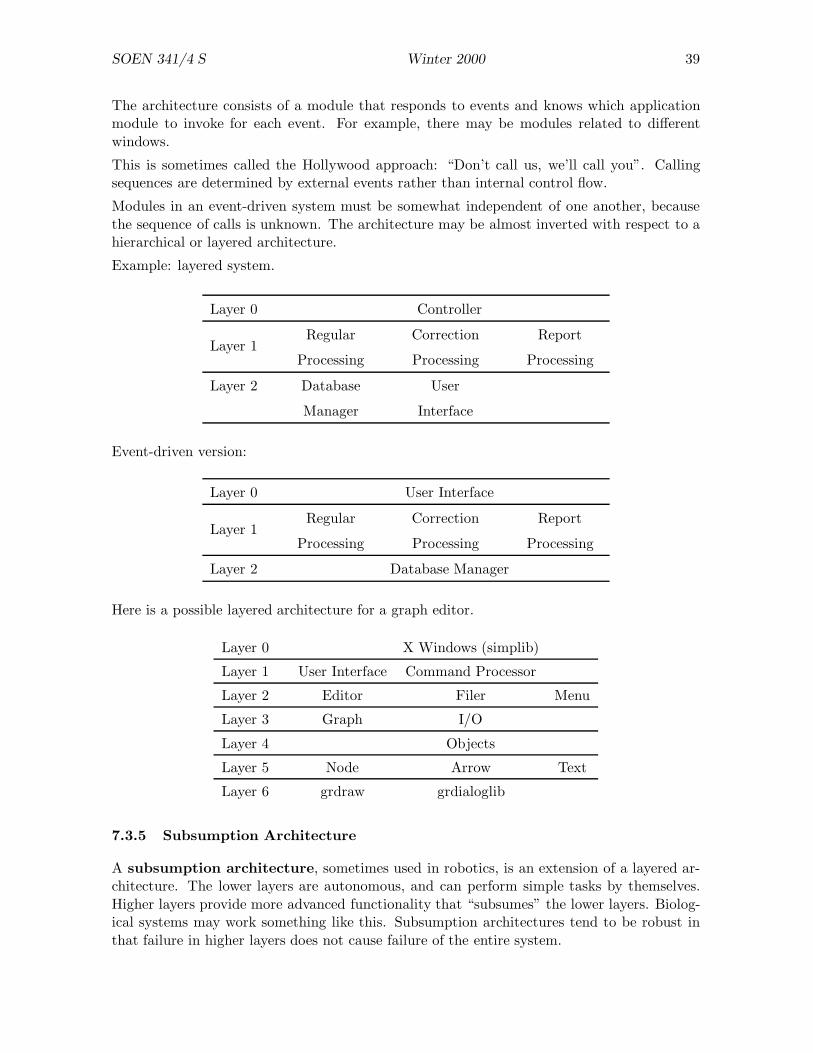
SOEN 341/4 S Winter 2000 39
The architecture consists of a module that responds to events and knows which applicationmodule to invoke for each event. For example, there may be modules related to differentwindows.
This is sometimes called the Hollywood approach: “Don’t call us, we’ll call you”. Callingsequences are determined by external events rather than internal control flow.
Modules in an event-driven system must be somewhat independent of one another, becausethe sequence of calls is unknown. The architecture may be almost inverted with respect to ahierarchical or layered architecture.
Example: layered system.
Layer 0 Controller
Layer 1Regular
Processing
Correction
Processing
Report
Processing
Layer 2 Database User
Manager Interface
Event-driven version:
Layer 0 User Interface
Layer 1Regular
Processing
Correction
Processing
Report
Processing
Layer 2 Database Manager
Here is a possible layered architecture for a graph editor.
Layer 0 X Windows (simplib)
Layer 1 User Interface Command Processor
Layer 2 Editor Filer Menu
Layer 3 Graph I/O
Layer 4 Objects
Layer 5 Node Arrow Text
Layer 6 grdraw grdialoglib
7.3.5 Subsumption Architecture
A subsumption architecture, sometimes used in robotics, is an extension of a layered ar-chitecture. The lower layers are autonomous, and can perform simple tasks by themselves.Higher layers provide more advanced functionality that “subsumes” the lower layers. Biolog-ical systems may work something like this. Subsumption architectures tend to be robust inthat failure in higher layers does not cause failure of the entire system.
SOEN 341/4 S Winter 2000 40
7.4 Designing for Change
What might change?
1. Users typically want more:
• commands;• reports;• options;• fields in a record.
Solutions include:
Abstraction Example: abstract all common features of commands so that it is easy toadd a new command. The ideal would be to add the name of a new command to atable somewhere and add a function to implement the command to the appropriatemodule.
Constant Definitions There should be no “magic numbers” in the code.Parameterization If the programming language allows parameterization of modules,
use it. C++ provides templates. Ada packages can be parameterized.
2. Unanticipated errors may occur and must be processed.
Incorporate general-purpose error detection and reporting mechanisms. It may be agood idea to put all error message text in one place, because this makes it easier tochange the language of the application.
3. Algorithm changes might be required.
Usually a faster algorithm is needed. As far as possible, an algorithm should be confinedto a single module, so that installing a better algorithm requires changes to only onemodule.
4. Data may change.
Usually a faster or smaller representation is needed. It is easy to change data represen-tations if they are “secrets” known to only a small number of modules.
5. Change of platform (processor, operating system, peripherals, etc)
Keep system dependencies localized as much as possible.
6. Large systems exist in multiple versions:
• different releases• different platforms• different devices
We need version control to handle different versions. RCS is a version control program.
Versions often form a tree, but there are variations. The more complicated the “versiongraph”, the harder it is to ensure that all versions are consistent and correct.
Note that a single technique can accommodate a large proportion of changes: good modulestructure, and secrets kept within modules. Avoid distributing information throughout thesystem.
SOEN 341/4 S Winter 2000 41
7.5 Module Design
Ideas about module design are important for both AD and MIS.
7.5.1 Language Support
The programming language has a strong influence on the way that modules can be designed.
• Turbo-Pascal provides units which can be used as modules. A unit has an “interfacepart” and an “implementation part” that provide separation of concern.
• C does not provide much for modularization. Conventional practice is to write a .h filefor the interface of a module and a .c file for its implementation. Since these files areused by both programmers and compilers, the interfaces contain information about theimplementation. For example, we can (and should) use typedefs to define types, butthe typedef declarations must be visible to clients.
• Modula-2 (based on MESA, developed at Xerox PARC) provides definition modules(i.e. interfaces) and implementation modules. The important idea that Wirth gotfrom PARC is that the interfaces can be compiled.
• Ada provides packages that are specifically intended for writing modular programs.Unfortunately, package interfaces and package bodies are separate, as in Modula-2.
• C++ does not provide any language features for structuring programs. The conventionalway of using C++ is to write a header file and an implementation file for each class.A group of related classes may be contained in a single header/implementation pair offiles.
• The modern approach is to have one physical file for the module and let the compilerextract the interfaces. This is the approach used in Eiffel and Java.
7.5.2 Examples of Modules
Example: a utility module for geometry.
Secret: Representations of geometric objects and algorithms for manipulating them.
Interface: Abstract data types such as Point, Line, Circle, etc. Functions such as these(which would be constructors in C++):
Line makeline (Point p1, p2)Point makepoint (Line l1, l2)Circle makecircle (Point c, float r)
Implementation: Representations for lines, circles, etc. (In C, these may be exposed in .hfiles. This is unfortunate but unavoidable.) Implementation of each function.

SOEN 341/4 S Winter 2000 42
Example: a stack module.
Secret: How stack components are stored (array, list, etc).
Interface: Functions Create, Push, Pop, Empty, Full.
Implementation: For the array representation, Full returns true if there are no more arrayelements available. The list representation returns false always (assuming memory isnot exhausted — but that is probably a more serious problem).
Example: a screen manager.
Secret: The relationship between stored and displayed data.
Invariant: The objects visible on the screen correspond to the stored data.
Interface: Display: add object to store and display it.
Delete: erase object and remove it from store.
Hide: erase object (but keep in store).
Reveal: display a hidden object.
Implementation: An indexed container for objects (or pointers to objects) and functionsto draw and erase objects.
7.5.3 A Recipe for Module Design
1. Decide on a secret.
2. Review implementation strategies to ensure feasibility.
3. Design the interface.
4. Review the interface. Is it too simple or too complex? Is it coherent?
5. Plan the implementation. E.g. choose representations.
6. Review the module.
• Is it self-contained?
• Does it use many other modules?
• Can it accommodate likely changes?
• Is it too large (consider splitting) or too small (consider merging)?

SOEN 341/4 S Winter 2000 43
7.6 Design Notations
A design can be described by diagrams, by text, or (preferably) by both.
Diagrams are useful to provide an overview of the design, showing how the parts relate toone another. Text (“textual design notation”, TDN) can be more precise, and as detailed asnecessary, but it may not be easy to see the overall plan from a textual design.
Text and graphics are complementary, with graphics working at a higher level of abstraction.Some people favour elaborate graphical notations with thick, thin, and dashed lines; single,double, and crossed arrow heads; ovals, rectangles, and triangles; and so on. My opinionis that a graphical notation should be simple, reflecting the essential relationships betweencomponents, and the detail should be in the text.
There are many advantages in having a design notation that is sufficiently formal to bemanipulated by software tools. Then we can use computers to help us design software.
The UPEDU uses notations adapted from the RUP. The diagrams include class diagrams,interaction diagrams, collaboration diagrams, and state diagrams.
7.7 Design Strategies
If you are a good designer, you can use any design strategy. If you are a bad designer, nostrategy will help you.
We need a strategy, or plan, to develop the design. Strategies and architectures are related,in that a particular strategy will tend to lead to a particular architecture, but there is not atight correspondence. For example, functional design tends to give a hierarchical architecture,but does not have to.
7.7.1 Functional Design
• Base the design on the functions of the system.
• Similar to writing a program by considering the procedures needed.
• A functional design is usually a hierarchy (perhaps with some layering) with “main” atthe root.
• Compatible with “top-down design and stepwise refinement”.
Strengths:
• Functional design works well for small problems with clearly-defined functionality.
Weaknesses:
• Leads to over-specialized leaf modules.
• Does not lead to reusable modules.
• Emphasis on functionality leads to poor handling of data. For example, data structuresmay be accessible throughout the system.
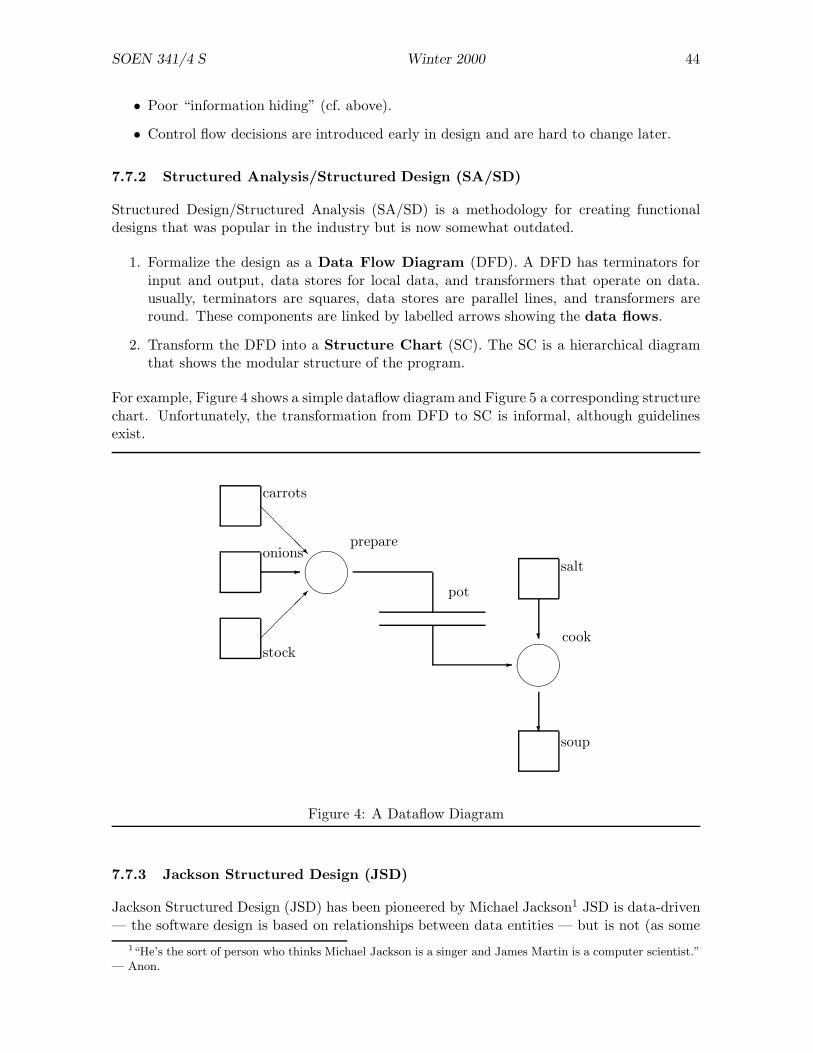
SOEN 341/4 S Winter 2000 44
• Poor “information hiding” (cf. above).
• Control flow decisions are introduced early in design and are hard to change later.
7.7.2 Structured Analysis/Structured Design (SA/SD)
Structured Design/Structured Analysis (SA/SD) is a methodology for creating functionaldesigns that was popular in the industry but is now somewhat outdated.
1. Formalize the design as a Data Flow Diagram (DFD). A DFD has terminators forinput and output, data stores for local data, and transformers that operate on data.usually, terminators are squares, data stores are parallel lines, and transformers areround. These components are linked by labelled arrows showing the data flows.
2. Transform the DFD into a Structure Chart (SC). The SC is a hierarchical diagramthat shows the modular structure of the program.
For example, Figure 4 shows a simple dataflow diagram and Figure 5 a corresponding structurechart. Unfortunately, the transformation from DFD to SC is informal, although guidelinesexist.
carrots
onions
stock
salt
soup
����prepare
����cook
pot
@@
@@R
-
��
���
-
?
?
Figure 4: A Dataflow Diagram
7.7.3 Jackson Structured Design (JSD)
Jackson Structured Design (JSD) has been pioneered by Michael Jackson1 JSD is data-driven— the software design is based on relationships between data entities — but is not (as some
1“He’s the sort of person who thinks Michael Jackson is a singer and James Martin is a computer scientist.”— Anon.
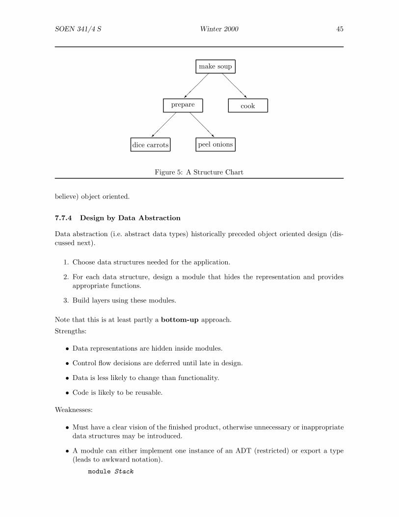
SOEN 341/4 S Winter 2000 45
dice carrots
prepare
make soup
peel onions
cook�
��
�
��
��
@@
@@R
@@
@@R
Figure 5: A Structure Chart
believe) object oriented.
7.7.4 Design by Data Abstraction
Data abstraction (i.e. abstract data types) historically preceded object oriented design (dis-cussed next).
1. Choose data structures needed for the application.
2. For each data structure, design a module that hides the representation and providesappropriate functions.
3. Build layers using these modules.
Note that this is at least partly a bottom-up approach.
Strengths:
• Data representations are hidden inside modules.
• Control flow decisions are deferred until late in design.
• Data is less likely to change than functionality.
• Code is likely to be reusable.
Weaknesses:
• Must have a clear vision of the finished product, otherwise unnecessary or inappropriatedata structures may be introduced.
• A module can either implement one instance of an ADT (restricted) or export a type(leads to awkward notation).
module Stack

SOEN 341/4 S Winter 2000 46
exports StackType
.....end.....var S: StackType
beginStack.Push(S, x ).....
7.7.5 Design by Use Cases
Some people advocate basing the design on use cases. The problem with this approach is thatit may get the “boundaries” of the system (interactions between the system and its users)right but fail to do a good job of the “heart” of the system where the real work is done.
However, use cases can provide an effective means of testing a design: if the design cannothandle a use case, it has to be improved.
7.8 Object Oriented Design
It makes little sense to discuss object oriented design without first describing the basic ideasof object oriented programming. Hence the next section (which may be omitted by those whoare already familiar with object oriented methodology).
7.8.1 Object Oriented Programming
Theory follows practice. Practitioners should listen to theorists, but only when the theoryhas matured. Examples: there is a mature theories for data structures and algorithms, butthere is not yet a theory for object oriented programming.
The object oriented approach extends ADTs. A module in an OOL is called a class.2 A classdeclaration contains declarations of instance variables, so-called because each instance ofthe class gets a copy of them. An instance of a class is called an object.
An object has:
• state (i.e. data);
• identity (e.g. address);
• methods (aka procedures and functions).
Equal states do not imply equal objects.3 In real life, a person may be arrested because theyhave the same description and SSN as another person: this is an example of equal “states”but unequal “objects”.
Methods are usually characterized as:
• Constructors create new objects.2The term “class” dates from Simula67.3Objects are intensional, not extensional.
SOEN 341/4 S Winter 2000 47
• Inspectors returns values.
• Mutators change objects.
A stack object might have:
• Constructor: Create.
• Inspectors: Empty, Full, Top.
• Mutators: Push, Pop.
Classes in object oriented programming play the role of modules in procedural programming.In fact, a class is somewhat more restricted than a module: it is essentially a module thatexports one type and some functions and procedures.
A class:
• is a collection of objects that satisfy the same protocol (or provide the same services);
• may have many instances (which are the objects).
All of this can be done with conventional techniques. OOP adds some new features.
Inheritance Suppose we have a class Window and we need a class ScrollingWindow. Wecould:
• rewrite the class Window from scratch;
• copy some code from Window and reuse it;
• inherit Window and implement only the new functionality.
class ScrollingWindow
inherits Window
— new code to handle scroll bars etc.— redefine methods of Window that no longer work
Inheritance is important because it is an abstraction mechanism that enables us to developa specialized class from a general class.
Inheritance introduces a two new relationships between classes.
• The first relationship is called is-a. For example: “a scrolling window is a window.”
If X is-a Y it should be possible to replace Y by X in any sentence without losingthe meaning of the sentence. Similarly, in a program, we should be able to replace aninstance of Y by an instance of X , or perform an assignment Y := X .
For example, a dog is an animal. We can replace “animal” by “dog” in any sentence,but not the other way round.4 In a program, we could write A := D where A : Animaland D : Dog.
4Consider “Animals have legs” and “Dogs bark”.
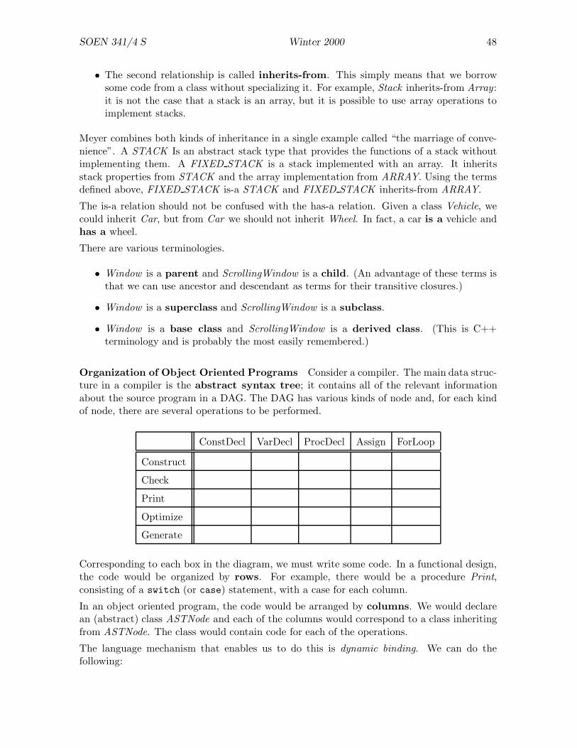
SOEN 341/4 S Winter 2000 48
• The second relationship is called inherits-from. This simply means that we borrowsome code from a class without specializing it. For example, Stack inherits-from Array :it is not the case that a stack is an array, but it is possible to use array operations toimplement stacks.
Meyer combines both kinds of inheritance in a single example called “the marriage of conve-nience”. A STACK Is an abstract stack type that provides the functions of a stack withoutimplementing them. A FIXED STACK is a stack implemented with an array. It inheritsstack properties from STACK and the array implementation from ARRAY. Using the termsdefined above, FIXED STACK is-a STACK and FIXED STACK inherits-from ARRAY.
The is-a relation should not be confused with the has-a relation. Given a class Vehicle, wecould inherit Car, but from Car we should not inherit Wheel. In fact, a car is a vehicle andhas a wheel.
There are various terminologies.
• Window is a parent and ScrollingWindow is a child. (An advantage of these terms isthat we can use ancestor and descendant as terms for their transitive closures.)
• Window is a superclass and ScrollingWindow is a subclass.
• Window is a base class and ScrollingWindow is a derived class. (This is C++terminology and is probably the most easily remembered.)
Organization of Object Oriented Programs Consider a compiler. The main data struc-ture in a compiler is the abstract syntax tree; it contains all of the relevant informationabout the source program in a DAG. The DAG has various kinds of node and, for each kindof node, there are several operations to be performed.
ConstDecl VarDecl ProcDecl Assign ForLoop
Construct
Check
Optimize
Generate
Corresponding to each box in the diagram, we must write some code. In a functional design,the code would be organized by rows. For example, there would be a procedure Print,consisting of a switch (or case) statement, with a case for each column.
In an object oriented program, the code would be arranged by columns. We would declarean (abstract) class ASTNode and each of the columns would correspond to a class inheritingfrom ASTNode. The class would contain code for each of the operations.
The language mechanism that enables us to do this is dynamic binding. We can do thefollowing:
SOEN 341/4 S Winter 2000 49
AstNode Node ;.....Node := ForNode;Node.Print
• The assignment statement is legal because we are allowed to assign a value of a derivedclass to a variable of the base class. In general, we can write x := y if y is-a x, but notthe other way round.
• The statement Node.Print is legal because AstNode and all its derived classes providethe method Print. Note that the compiler cannot determine the class (type) of Node.
• At run-time, the program must choose the appropriate code for Print based on the classof Node. A simple implementation uses a pointer from the object to a class descriptorconsisting of an array of pointers to functions.
With a functional design, it would be easy to add a row to the table: this corresponds towriting one function with a case for each node type. But it is unlikely that we would want todo this because the functional requirements of a compiler are relatively static. It is harder toadd a column to the table, because this means altering the code in many different places.
With the object oriented design, it is easy to add a column to the table, because we just haveto declare a new derived class of Node. On the other hand, it is hard to add a row, becausethis would mean adding a new method to each derived class of Node.
On balance, the pros and cons favour the object oriented approach. All changes are additions,rather than changes, and the expected changes (adding to the varieties of a data structure)are easier to make.
Dynamic Binding Consider these classes:
class Animal
method Sound .....
class Dog
inherits Animal
method Sound
return "bark"
class Cat
inherits Animal
method Sound
return "miaow"
and assume
A : AnimalC : CatD : Dog
The assignments A := C and D := C are allowed, because a cat is-a animal and a dog is-aanimal. We can also write
SOEN 341/4 S Winter 2000 50
if P then A := C else D := CA . Sound
The compiler cannot determine which version of Sound to call, because the correct methoddepends on the value of the predicate P . Consequently, it must generate code to call eitherSound in class Cat (if P is true) or Sound in class Dog (if P is false). The “binding”between the name “Sound” and the code is established at run-time. We say that objectoriented languages use dynamic binding for method calls. Conventional languages usestatic binding — the function name and code are matched at compile-time.
Contracts Meyer introduced the expression “programming by contract”. A method hasrequires and ensures clauses and is not required to do anything at all if its requires clauseis not satisfied on entry. The contractual approach reduces redundant code because theimplementor is not required to check preconditions. For example, a squareroot function thatrequires a positive argument does not have to check the value of its argument.
Meyer also explained how contracts could be used to ensure correct behaviour in subclasses.Consider the following classes.
class PetShop
method Order
requires: Payment ≥ $10ensures: animal delivered
class DogShop
inherits PetShop
method Order
requires: Payment ≥ $5ensures: dog delivered
The ensures clause is strengthened: delivering a dog is a stronger requirement than deliveringan animal. (To see this, note that if you asked for an animal and received a dog, you wouldhave no grounds for complaint. But if you asked for a dog and received some other kind ofanimal, you would complain.)
Surprisingly, the requires clause is weakened: the dog shop requires only $5. To see why,consider the following code.
P : PetShopD : DogShopA : Animal.....P := DA := P . Order (12)
The assignment P := D is valid because DogShop inherits from PetSHop. The result ofP . Order (10) will be a dog, and we can assign this dog to A.
The payment for the dog, $12, must satisfy the requires clause of Order in PetShop, becauseP is a PetShop, and it does so (12 ≥ 10). It must also satisfy the requires clause of Orderin DogShop, because at run-time P is actually a DogShop.
Note that if we had strengthened the requires clause of Order in DogShop as in

SOEN 341/4 S Winter 2000 51
method Order
requires: Payment ≥ $15ensures: dog delivered
then the statement A := P . Order (12) would have compiled but have failed at run-time. Insummary, the rule that we weaken the requires clause and strengthen the ensures clause inan inherited class has the desired effect: the static meaning of the program is consistent withits run-time effect.
Frameworks An abstract class defines a pattern of behaviour but not the precise detailedof that behaviour: for example, see AstNode above. A collection of abstract classes can providean architecture for a family of programs. Such a collection is called a framework.
We can use predefined functions, together with functions that we write ourselves, to constructa library. The main program obtains basic services by calling functions from the library, asshown in Figure 6. The structure of the system is determined by the main program; thelibrary is a collection of individual components.
Main Program
?
���� ?
���� ?
���� ?
����Application
Library
Figure 6: A Program Using Components from a Library
Using object oriented techniques, we can reverse the relationship between the library and themain program. Instead of the application calling the library, the library calls the application.A library of this kind is referred to as a framework. A framework is a coherent collectionof classes that contain deferred methods. The deferred methods are “holes” that we fill inwith methods that are specific to the application. The organization of a program constructedfrom a framework is shown in Figure 7. The structure of the system is determined by theframework; the application is a collection of individual components.
Framework
?
���� ?
���� ?
���� ?
����Library
Application
Figure 7: A Program Using a Framework from a Library
The best-known framework is the MVC triad of Smalltalk. It is useful for simulations andother applications. The components of the triad are a model, a view and a controller — see

SOEN 341/4 S Winter 2000 52
Figure 8.
Model
Controller
View
���������
HHHHHHHHj
Figure 8: The Model-View-Controller Framework
The Model is the entity being simulated. It must respond to messages such as step (performone step of the simulation) and show (reveal various aspects of its internal data).
The View provides one or more ways of presenting the data to the user. View classes mightinclude DigitalView, GraphicalView, BarChartView, etc.
The Controller coordinates the actions of the model and the view by sending appropriatemessages to them. Roughly, it will update the model and then display the new view.
Smalltalk provides many classes in each category and gives default implementations of theirmethods. To write a simulation, all you have to do is fill in the gaps.
A framework is a kind of upside-down library. The framework calls the application classes,rather than the application calling library functions. Frameworks are important because theyprovide a mechanism for design re-use.
7.8.2 Responsibility-Driven Design
Wirfs-Brock et al suggest that the best way to find good objects is to consider the responsi-bility of each object. The following summary of their method is adapted from Wirfs-Brock.The ideas here are useful for other design methodologies, as well as OOD.
Classes
1. Make a list of noun phrases in the requirements document. Some nouns may be hidden(for example, by passive usage).
2. Identify candidate classes from the noun phrases using the following guidelines.
• Model physical objects.
• Model conceptual entities.
• Use a single term for each concept.
• Avoid adjectives. (A class HairyDog is probably a mistake: it’s Dog with a partic-ular value, or perhaps derived from Dog.)
• Model: categories of objects, external interfaces, attributes of an object.
3. Group classes with common attributes to produce candidates for abstract base classes.

SOEN 341/4 S Winter 2000 53
4. Use categories to look for classes that may be missing.
5. Write a short statement describing the purpose of each class.
Responsibilities
1. Find responsibilities:
• Recall the purpose of each class.
• Extract responsibilities from the requirements.
• Identify responsibilities from relations between classes.
2. Assign responsibilities to classes:
• Evenly distribute system intelligence.
• State responsibilities as generally as possible.
• Keep behaviour with related information.
• Keep information about one thing in one place.
• Share responsibilities among related classes.
3. Find additional responsibilities by looking for relationships between classes.
• Use “is-kind-of” to find inheritance.
• Use “is-analogous-to” to find base classes.
• Use “is-part-of” (or “has-a”) to find suppliers and clients.
Collaborations
1. Find collaborations by examining the responsibilities associated with classes. Examples:Which classes does this class need to fulfill its responsibilities? Who needs to use theresponsibilities assigned to this class?
2. Identify additional collaborations by examining relations between classes. Consider “is-part-of”, “has-knowledge-of”, and “depends-on”.
3. Discard classes that have no collaborations.
The process continues by building class hierarchies from the relationships already established.Wirfs-Brock et al also provide conventions for drawing diagrams.
7.9 Functional or Object Oriented?
7.9.1 Functional Design (FD)
• FD is essentially top-down. It emphasizes control flow and tends to neglect data.
• Information hiding is essentially bottom-up. It emphasizes encapsulation (“secrets”) inlow-level modules.

SOEN 341/4 S Winter 2000 54
• In practice, FD must use both top-down and bottom-up techniques.
• FD uses function libraries.
• FD is suitable for small and one-off projects.
7.9.2 Object Oriented Design (OOD)
• OOD is also top-down and bottom-up, but puts greater emphasis on the bottom-updirection, because we must define useful, self-contained classes.
• OOD emphasizes data and says little about control flow. In fact, the control flow emergesimplicitly at quite a late stage in the design.
• Inheritance, used carefully, provides separation of concern, modularity, abstraction, an-ticipation of change, generality, and incrementality.
• OOD is suitable for large projects and multi-version programs.
7.10 Writing MIS and IMD
Design is not implementation. Module interface specifications (MIS) should be at a higherlevel of abstraction than internal module designs (IMD), and IMD should be at a higher levelthan code. One way of achieving a higher level is to write declarative (“what”) statementsrather than procedural (“how”) statements.
7.10.1 Module Interface Specifications
Use requires/ensures where possible, otherwise clear but informal natural language (e.g. En-glish).
You can use pre/post instead of requires/ensures. The advantage of requires/ensures is thatthese verbs suggest the use of the predicates more clearly than the labels pre and post.
An MIS often uses some of the syntax of the target language. This helps the implementors.Pascal style:
function Int String (N : integer) : Stringensures: result is the shortest string representing N
C style:
int String Int (char ∗ s)requires: s consists of optional sign followed by decimal digitsensures: result is the integer represented by s
When there are several cases, it may help to use several pairs of requires/ensures classes.Rather than
void Line (Point p, Point q)ensures: if p and q are in the workspace
then a line joining them is displayedelse nothing happens.
write this:
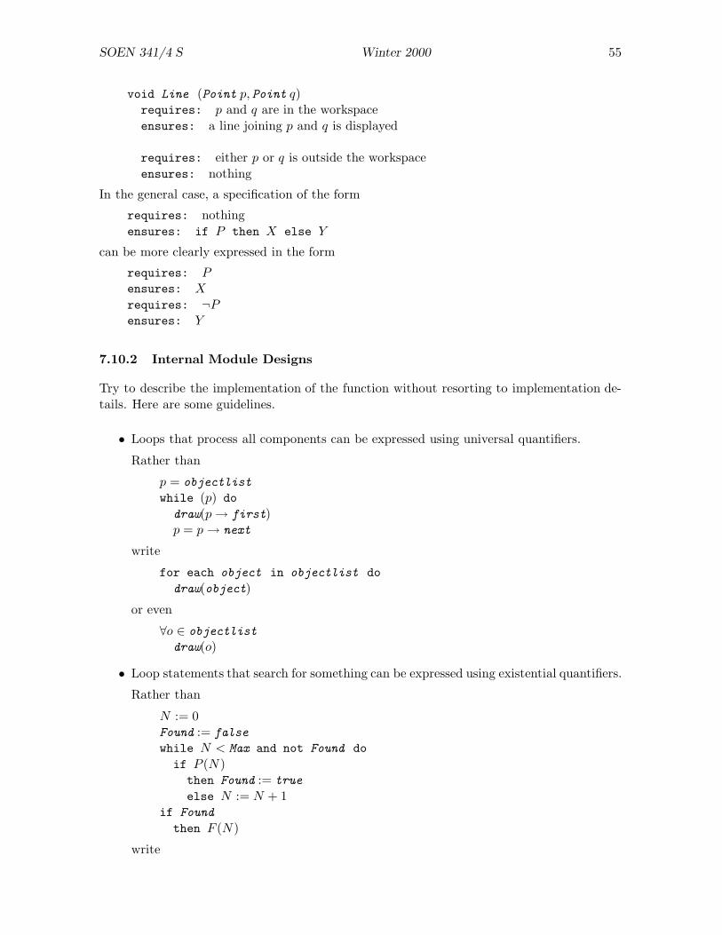
SOEN 341/4 S Winter 2000 55
void Line (Point p, Point q)requires: p and q are in the workspaceensures: a line joining p and q is displayed
requires: either p or q is outside the workspaceensures: nothing
In the general case, a specification of the form
requires: nothingensures: if P then X else Y
can be more clearly expressed in the form
requires: Pensures: X
requires: ¬Pensures: Y
7.10.2 Internal Module Designs
Try to describe the implementation of the function without resorting to implementation de-tails. Here are some guidelines.
• Loops that process all components can be expressed using universal quantifiers.
Rather than
p = objectlist
while (p) dodraw(p → first)p = p → next
write
for each object in objectlist dodraw(object)
or even
∀o ∈ objectlist
draw(o)
• Loop statements that search for something can be expressed using existential quantifiers.
Rather than
N := 0Found := false
while N < Max and not Found doif P (N)
then Found := true
else N := N + 1if Found
then F (N)
write
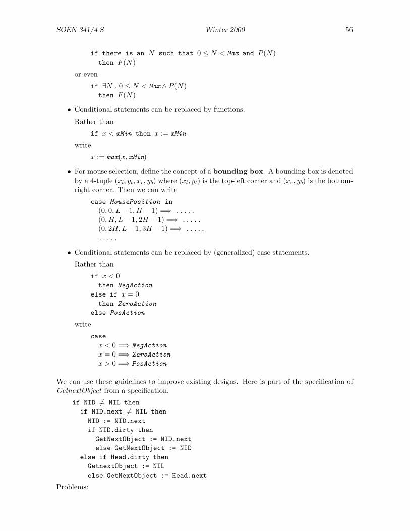
SOEN 341/4 S Winter 2000 56
if there is an N such that 0 ≤ N < Max and P (N)then F (N)
or even
if ∃N . 0 ≤ N < Max∧ P (N)then F (N)
• Conditional statements can be replaced by functions.
Rather than
if x < xMin then x := xMin
write
x := max(x, xMin)
• For mouse selection, define the concept of a bounding box. A bounding box is denotedby a 4-tuple (xl, yt, xr, yb) where (xl, yt) is the top-left corner and (xr, yb) is the bottom-right corner. Then we can write
case MousePosition in(0, 0, L− 1, H − 1) =⇒ .....(0, H, L− 1, 2H − 1) =⇒ .....(0, 2H, L− 1, 3H − 1) =⇒ ..........
• Conditional statements can be replaced by (generalized) case statements.
Rather than
if x < 0then NegAction
else if x = 0then ZeroAction
else PosAction
write
casex < 0 =⇒ NegAction
x = 0 =⇒ ZeroAction
x > 0 =⇒ PosAction
We can use these guidelines to improve existing designs. Here is part of the specification ofGetnextObject from a specification.
if NID 6= NIL thenif NID.next 6= NIL then
NID := NID.nextif NID.dirty then
GetNextObject := NID.nextelse GetNextObject := NID
else if Head.dirty thenGetnextObject := NILelse GetNextObject := Head.next
Problems:
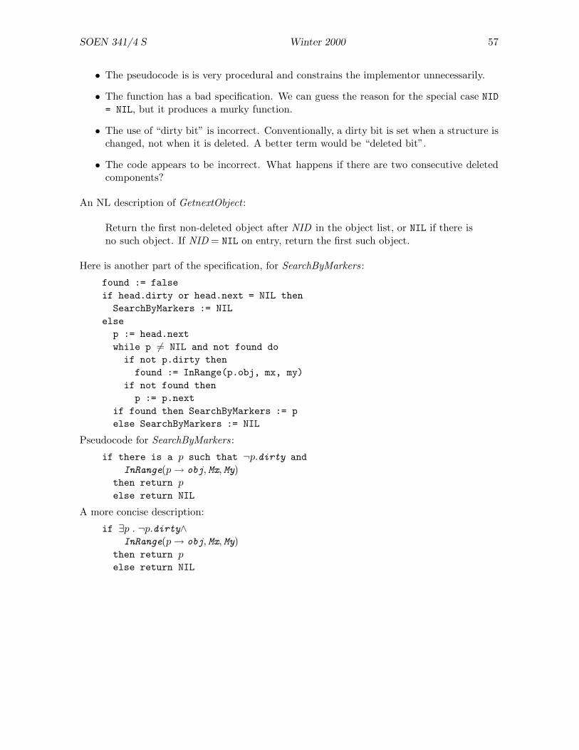
SOEN 341/4 S Winter 2000 57
• The pseudocode is is very procedural and constrains the implementor unnecessarily.
• The function has a bad specification. We can guess the reason for the special case NID= NIL, but it produces a murky function.
• The use of “dirty bit” is incorrect. Conventionally, a dirty bit is set when a structure ischanged, not when it is deleted. A better term would be “deleted bit”.
• The code appears to be incorrect. What happens if there are two consecutive deletedcomponents?
An NL description of GetnextObject :
Return the first non-deleted object after NID in the object list, or NIL if there isno such object. If NID = NIL on entry, return the first such object.
Here is another part of the specification, for SearchByMarkers :
found := falseif head.dirty or head.next = NIL then
SearchByMarkers := NILelse
p := head.nextwhile p 6= NIL and not found do
if not p.dirty thenfound := InRange(p.obj, mx, my)
if not found thenp := p.next
if found then SearchByMarkers := pelse SearchByMarkers := NIL
Pseudocode for SearchByMarkers :
if there is a p such that ¬p.dirty andInRange(p → obj, Mx, My)
then return p
else return NIL
A more concise description:
if ∃p . ¬p.dirty∧InRange(p → obj, Mx, My)
then return pelse return NIL
SOEN 341/4 S Winter 2000 58
8 Object Oriented Development
This section is adapted from notes made from an earlier version of a software engi-neering course. It mentions process models such as Fusion that are predecessors ofRUP.
Object oriented methods started off with programming languages such as Simula (1967) andSmalltalk (1976) and gradually crept backwards through the life cycle: OO programmingrequire OO design, which in turn required OO analysis. A variety of methods have beenproposed for object oriented software development, including:
• Object Modeling Technique (OMT).
• Booch’s method
• Objectory
• Class Responsibility Collaborator (CRC).
• Fusion.
• RUP/UPEDU.
The Fusion method,5 developed at Hewlett-Packard (UK) is the most recent method and it is,to some extent, based on earlier methods. We describe it here. The Fusion model is presentedin “waterfall” form but it can be adapted for a spiral (risk-driven) approach or for incrementaldevelopment.
The major phases of the Fusion method (as for other methods) are as follows. Note that allphases produce models of the system.
Analysis produces a specification of what the system does, based on a requrements docu-ment. The result of analysis is a specification document.
Analysis models describe:
• Classes that exist in the system
• Relationships between the classes
• Operations that can be performed on the system
• Allowable sequences of operations
Design starts from the specification document and determines how to obtain the systembehaviour from the given requirements. The result is an architecture document.
Design models describe:
• how system operations are implemented by interacting objects
• how classes refer to one another and how they are related by inheritance
• attributes and operations for each class5Fusion seems to have evolved into ColdFusion, a process for developing fancy websites.

SOEN 341/4 S Winter 2000 59
Implementation starts from the architecture document and encodes the design in a pro-gramming language. The result is source code.
Design features are mapped to code as follows:
• inheritance, references, and attributes are implemented using corresponding fea-tures of the target language (specifically, class definitions)
• object interactions are implemented as methods in the appropriate classes
• state machines (usually not explicitly coded) define permissible sequences of oper-ations
A data dictionary is maintained for all stages of development. Figure 9 shows part of adata dictionary. The data dictoinary is called a glossary in UPEDU.
customer agent delivers gas using the gun and makes payment
timer agent turns off the pump motor a certain time after the pump has beendisabled
enable-pump sys op enables the pump to start pumping gas unless the pump is out ofservice
remove-gun sys op enables the gun to start pumping gas when the trigger is depressed
start-timer event starts the timer for turning off the pump motor
display-amount event details of the current delivery are shown on the display
Figure 9: Extract from a Data Dictionary
8.1 Analysis
The main purpose of analysis is to identify the objects of the system. Analysis yields anobject model and an interface model.
Important features of objects include:
• An object can have one or more attributes associated with it. Each attribute is a valuechosen from a basic type such as Boolean, integer , float , or string.
(Note: the Fusion method does not allow attributes to be objects during the analysisphase.)
Example: a Person object might have attributes name, address, SIN, . . . .
• The number of attributes, and the name of each attribute, is fixed (for a given object).
• The value of an attribute can change during the lifetime of the object.
• An object can be identified (or: “has identity”). An object may be a specific person,organization, machine, event, document, . . . .
If X and Y are objects, we distinguish “X and Y are the same object” from “X and Yhave equal attributes”. This is like real life: two people can have the same name andyet be distinct persons.
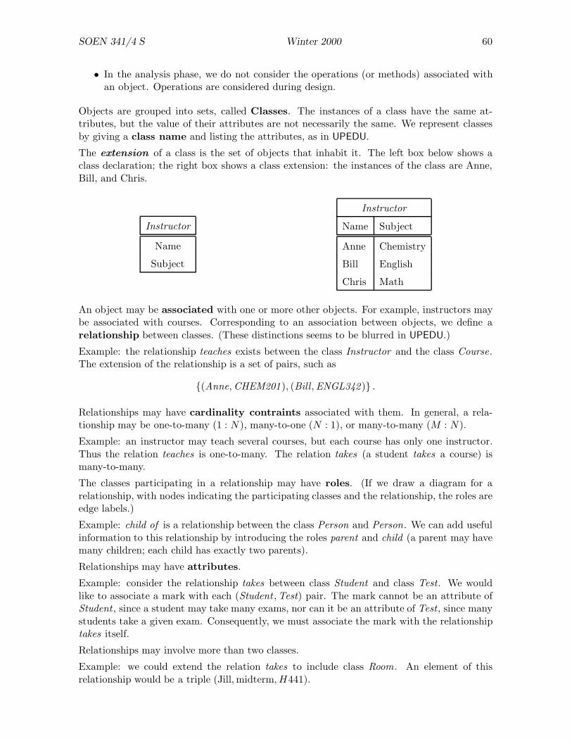
SOEN 341/4 S Winter 2000 60
• In the analysis phase, we do not consider the operations (or methods) associated withan object. Operations are considered during design.
Objects are grouped into sets, called Classes. The instances of a class have the same at-tributes, but the value of their attributes are not necessarily the same. We represent classesby giving a class name and listing the attributes, as in UPEDU.
The extension of a class is the set of objects that inhabit it. The left box below shows aclass declaration; the right box shows a class extension: the instances of the class are Anne,Bill, and Chris.
Instructor
Name
Subject
Instructor
Name Subject
Anne Chemistry
Bill English
Chris Math
An object may be associated with one or more other objects. For example, instructors maybe associated with courses. Corresponding to an association between objects, we define arelationship between classes. (These distinctions seems to be blurred in UPEDU.)
Example: the relationship teaches exists between the class Instructor and the class Course.The extension of the relationship is a set of pairs, such as
{(Anne, CHEM201), (Bill, ENGL342)} .
Relationships may have cardinality contraints associated with them. In general, a rela-tionship may be one-to-many (1 : N), many-to-one (N : 1), or many-to-many (M : N).
Example: an instructor may teach several courses, but each course has only one instructor.Thus the relation teaches is one-to-many. The relation takes (a student takes a course) ismany-to-many.
The classes participating in a relationship may have roles. (If we draw a diagram for arelationship, with nodes indicating the participating classes and the relationship, the roles areedge labels.)
Example: child of is a relationship between the class Person and Person. We can add usefulinformation to this relationship by introducing the roles parent and child (a parent may havemany children; each child has exactly two parents).
Relationships may have attributes.
Example: consider the relationship takes between class Student and class Test. We wouldlike to associate a mark with each (Student , Test) pair. The mark cannot be an attribute ofStudent , since a student may take many exams, nor can it be an attribute of Test, since manystudents take a given exam. Consequently, we must associate the mark with the relationshiptakes itself.
Relationships may involve more than two classes.
Example: we could extend the relation takes to include class Room . An element of thisrelationship would be a triple (Jill, midterm, H441).
SOEN 341/4 S Winter 2000 61
Another way of combining classes is to put one or more classes into an aggregate class.
Example: we can build an aggregate class Option as follows. Option has:
• an attribute name (e.g. "Software Systems").
• component classes Student and Course linked by takes (the only students in an optionare those who take the courses appropriate for the option).
Generalization allows us to abstract the common properties of several subclasses (or de-rived classes) into a superclass (or base class).
Eaxmple: suppose that there are undergraduate courses and graduate courses. Then theclass Course is a generalization of the two kinds of course. That is, we could make Course asuperclass with the subclasses GradCourse and UGradCourse.
Once we have generalized, we can move the common attributes of the subclasses into thesuperclass.
Example: since all courses have attributes time and room , these could be attributes of classCourse. But only undergraduate courses have tutorials, so we could not make tutorial anattribute of Course.
Multiple generalization is also allowed.
Example: → reads “specializes to”.
Instructor → FullTimeInstructor
Instructor → PartTimeInstructor
PartTimeInstructor → GradInstr
Student → GraduateStudent
GraduateStudent → GradInstr
Note that generalization and its inverse, specialization, correspond to “inheritance” in OOprogramming languages.
The analysis phase yields two models: the System Object Model and and Interface Model.
8.1.1 System Object Model
The collection of classes will include classes that belong to the environment and classes thatbelong to the system. The System Object Model (SOM) excludes the environment classesand focuses on the system classes. The SOM describes the structure of the system but notits behaviour.
8.1.2 Interface Model
The system can also be modelled as a collection of interacting agents. One agent is the systemitself; the other agents are “things in the world”, such as users, hardware devices, and so on.Agents communicate by means of events. We are interested primarily in communication withthe system, although it may be necessary during analysis to consider communication betweenagents other than the system.
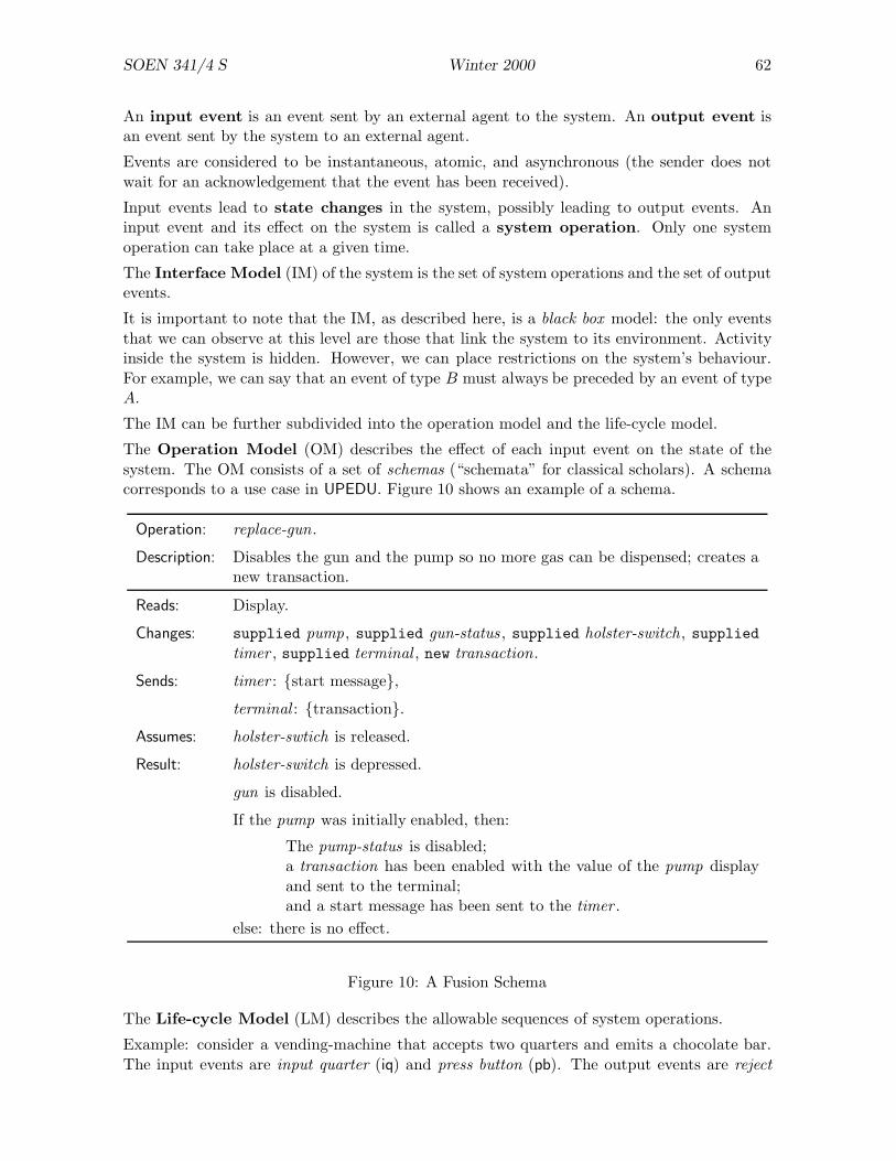
SOEN 341/4 S Winter 2000 62
An input event is an event sent by an external agent to the system. An output event isan event sent by the system to an external agent.
Events are considered to be instantaneous, atomic, and asynchronous (the sender does notwait for an acknowledgement that the event has been received).
Input events lead to state changes in the system, possibly leading to output events. Aninput event and its effect on the system is called a system operation. Only one systemoperation can take place at a given time.
The Interface Model (IM) of the system is the set of system operations and the set of outputevents.
It is important to note that the IM, as described here, is a black box model: the only eventsthat we can observe at this level are those that link the system to its environment. Activityinside the system is hidden. However, we can place restrictions on the system’s behaviour.For example, we can say that an event of type B must always be preceded by an event of typeA.
The IM can be further subdivided into the operation model and the life-cycle model.
The Operation Model (OM) describes the effect of each input event on the state of thesystem. The OM consists of a set of schemas (“schemata” for classical scholars). A schemacorresponds to a use case in UPEDU. Figure 10 shows an example of a schema.
Operation: replace-gun.
Description: Disables the gun and the pump so no more gas can be dispensed; creates anew transaction.
Reads: Display.
Changes: supplied pump , supplied gun-status , supplied holster-switch , suppliedtimer , supplied terminal , new transaction.
Sends: timer : {start message},
terminal : {transaction}.
Assumes: holster-swtich is released.
Result: holster-switch is depressed.
gun is disabled.
If the pump was initially enabled, then:
The pump-status is disabled;a transaction has been enabled with the value of the pump displayand sent to the terminal;and a start message has been sent to the timer .
else: there is no effect.
Figure 10: A Fusion Schema
The Life-cycle Model (LM) describes the allowable sequences of system operations.
Example: consider a vending-machine that accepts two quarters and emits a chocolate bar.The input events are input quarter (iq) and press button (pb). The output events are reject
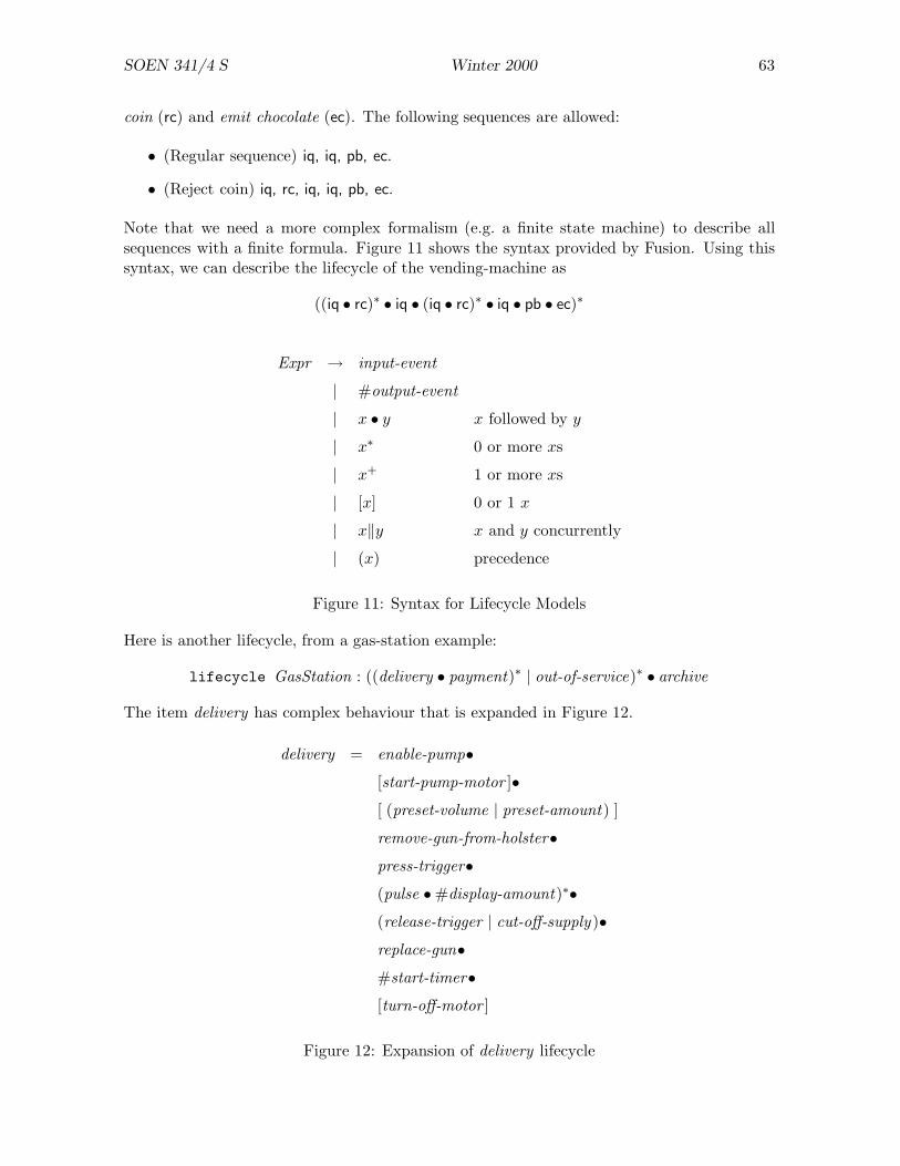
SOEN 341/4 S Winter 2000 63
coin (rc) and emit chocolate (ec). The following sequences are allowed:
• (Regular sequence) iq, iq, pb, ec.
• (Reject coin) iq, rc, iq, iq, pb, ec.
Note that we need a more complex formalism (e.g. a finite state machine) to describe allsequences with a finite formula. Figure 11 shows the syntax provided by Fusion. Using thissyntax, we can describe the lifecycle of the vending-machine as
((iq • rc)∗ • iq • (iq • rc)∗ • iq • pb • ec)∗
Expr → input-event
| #output-event
| x • y x followed by y
| x∗ 0 or more xs
| x+ 1 or more xs
| [x] 0 or 1 x
| x‖y x and y concurrently
| (x) precedence
Figure 11: Syntax for Lifecycle Models
Here is another lifecycle, from a gas-station example:
lifecycle GasStation : ((delivery • payment)∗ | out-of-service)∗ • archive
The item delivery has complex behaviour that is expanded in Figure 12.
delivery = enable-pump•
[start-pump-motor ]•
[ (preset-volume | preset-amount) ]
remove-gun-from-holster•
press-trigger•
(pulse • #display-amount)∗•
(release-trigger | cut-off-supply )•
replace-gun•
#start-timer•
[turn-off-motor ]
Figure 12: Expansion of delivery lifecycle
SOEN 341/4 S Winter 2000 64
Object oriented analysis has been criticized because it is too implementation oriented: thecritics say that objects should not be introduced so early in development. The Fusion methodavoids this problem:
• Fusion uses a highly abstract form of “object” in the analysis phase.
• All objects are (or can be) considered, not only those that will become part of the finalsystem.
• Objects that contain other objects are not allowed.
• Methods are not assigned to objects.
• Generalization and specialization are used, but not inheritance.
Thus it should be possible to complete analysis without too much implementation bias.
8.2 Design
The analysis models define a system as a collection of objects that has a specified response toparticular operations. The purpose of the design phase is to find a strategy for implementingthe specification. The output of the design phase consists of four parts.
• Object Interaction Graphs describe how objects interact at run-time.
• Visibility Graphs describe object communication paths.
• Class Descriptions describe class interfaces.
• Inheritance Graphs describe inheritance relationships between classes.
8.2.1 Object Interaction Graphs
Each operation of the system is described by an object interaction graph (OIG). The graphis a collection of boxes linked by arrows. The boxes represent design objects and the arrowsrepresent message passing.
A design object is an extended version of an analysis object. In addition to attributes, adesign object has a method interface. The arrows that enter a design object in an OIG arelabelled with method names and arguments.
When a message is sent to a design object, the corresponding method is assumed to be invoked.The method completes its task before returning control to the caller. Task completion mayrequire sending messages to other objects.
Invoking the method Create of an object creates a new instance of the object.
A design object with a dashed outline represents a collection of objects of the same class.The Fusion method provides conventions for sending a message to a collection: for example,it is possible to send a message to every member of a collection and to iterate through themembers of a collection.
OIGs are developed as follows.
SOEN 341/4 S Winter 2000 65
1. Identify the objects involved in a system operation. The reads and changes clause ofthe schemas identify the objects that are touched or modified by an operation.
2. Establish the role of each object.
• Identify the object that initiates the operation (this object is called the controller.
• Identify the other objects (these are called the collaborators). The sends clauseof a schema identifes messages sent by the object.
3. Choose appropriate messages between objects.
4. Record how the objects interact on an OIG.
After the OIGs have been constructed, they can be checked.
• Each object in the SOM should appear in at least one OIG. (Otherwise the object isapparently not required: there is something wrong with the SOM or with the design.)
• The effect of each OIG should agree with the operations described in the OM.
8.2.2 Visibility Graphs
If an OIG requires an object X to communicate with an object Y , then X must contain areference to Y . Visibility graphs (VGs) describe the references that objects need to participatein operations.
A VG consists of visibility arrows; client boxes (which have at least one visibility arrowemerging from them); and server boxes (which have at least one arrow entering them).
A server is bound to a client if the client has exclusive access to the server at all times. Inthis case, the server is drawn as a box inside the client box. A server that is not bound is saidto be unbound. Obviously, an unbound server cannot be shared.
Several factors must be taken into account while constructing the visibility graph:
• If X needs to access Y only when its method m is invoked, a reference to Y can bepassed as an argument of m. This is called a dynamic reference.
• If X needs to access Y many times, the reference should be created when X is created(it could, for example, be an argument of the constructor). This is called a permanentreference.
• A server may have a single client or many clients. Shared servers have a single borderin the OIG; exclusive servers have a double border.
• References may be constant (they never change) or variable (they may change at run-time).
8.2.3 Class Descriptions
Fusion class descriptions are conventional. Inheritance is indicated by an isa clause; attributesare listed; and methods are listed. Figure 13 shows an example of a class description.
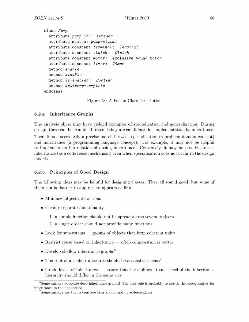
SOEN 341/4 S Winter 2000 66
class Pump
attribute pump-id: integer
attribute status; pump-status
attribute constant terminal: Terminal
attribute constant clutch: Clutch
attribute constant motor: exclusive bound Motor
attribute constant timer: Timer
method enable
method disable
method is-enabled: Boolean
method delivery-complete
endclass
Figure 13: A Fusion Class Description
8.2.4 Inheritance Graphs
The analysis phase may have yielded examples of specialization and generalization. Duringdesign, these can be examined to see if they are candidates for implementation by inheritance.
There is not necessarily a precise match between specialization (a problem domain concept)and inheritance (a programming language concept). For example, it may not be helpfulto implement an isa relationship using inheritance. Conversely, it may be possible to useinheritance (as a code reuse mechanism) even when specialization does not occur in the designmodels.
8.2.5 Principles of Good Design
The following ideas may be helpful for designing classes. They all sound good, but some ofthem can be harder to apply than appears at first.
• Minimize object interactions
• Cleanly separate functionality
1. a simple function should not be spread across several objects
2. a single object should not provide many functions
• Look for subsystems — groups of objects that form coherent units
• Restrict reuse based on inheritance — often composition is better
• Develop shallow inheritance graphs6
• The root of an inheritance tree should be an abstract class7
• Grade levels of inheritance — ensure that the siblings at each level of the inheritancehierarchy should differ in the same way
6Some authors advocate deep inheritance graphs! The best rule is probably to match the opportunities forinheritance to the application.
7Some authors say that a concrete class should not have descendants.
SOEN 341/4 S Winter 2000 67
• Use inheritance for subtyping — subclasses should always respect the properties of theirsuperclass(es)
8.3 Implementation
The main goals of implementation are correctness and economy (the software should notmake excessive use of time or space). Fusion is not associated with any particular programminglanguage, and implementation details will vary between languages.
Implementation is divided into three parts: coding, performance, and testing. These partscould be carried out sequentially but, in practice, it is best to interleave them.
8.3.1 Coding
Lifecycle models are translated into finite state machines which are implemented in the pro-gramming language. This is straightforward, apart from interleaving (x‖y).
Class descriptions from the design phase can easily be mapped into class declarations of mostOO languages. Bound objects can be embedded; unbound objects can be represented aspointers. If the language does not provide embedded objects (e.g. Smalltalk) then all objectsare represented as pointers. Constant attributes are initialized when the object is created butcannot be assigned.
8.3.2 Performance
Good performance is not achieved by a final “tuning” step but must be taken into accountthroughout implementation. A profiling tool should be used if possible, and effort shouldbe devoted to improving “hot spots” (portions of code that are executed very often).
• performance cannot be obtained as an afterthought
• optimizing rarely executed code is not effective
• profile the system in as many ways as you can
Consider language features such as
• inlined methods
1. don’t inline large functions (C++ does not allow this)2. excessive inlining will lead to “bloat” which may actually worsen performance on
a paged system3. when a class with inlines is changed, all clients must be recompiled
• using references rather than values (in C++, passing an object by value requires thecreation and destruction of an object)
• avoiding virtual methods (C++ only: actually the overhead of virtual methods is notvery great)
Note that, in C++, dynamic binding requires pointers to objects but operator overloadingrequires objects, not pointers. It is therefore difficult to build a “clean” system which usesobjects or pointers consistently.
SOEN 341/4 S Winter 2000 68
8.3.3 Review
All code should be reviewed. In Fusion terminology, inspection require that code be readand understood by people other than the authors. Testing checks the actual behaviour of thesystem.
It is hard to understand programs and particularly hard to understand OO programs. Sincemethods are often small (2–5 lines average) tracing even a simple system operation can belengthy and tedious. With dynamic binding, it can be effectively impossible.
Reviewers should pay particular attention to tricky language features, such as casts.
Code can be tested at different levels in an OO system:
Function: test individual methods.
Class: test invariants and check outputs for allowed sequences of method invocations.
Cluster: test groups of collaborating objects.
System: test entire system with external inputs and outputs.
8.3.4 Error Handling
In Fusion, an error is defined as the violation of a precondition8. Fusion distinguishes thedetection of errors and recovery from errors.
Error Detection We could detect errors by writing code to test the precondition in everymethod, but this is not a good idea:
• It may be difficult, inefficient, or impossible to express the precondition in the program-ming language. (Consider a matrix inversion function with precondition “|M | 6= 0” ora graph algorithm with the precondition “G is acyclic”.) Preconditions may refer toglobal properties of the system that cannot be checked within the method.
• Some preconditions are actually class invariants that should be true before and afterevery method of the class is executed.
Sometimes preconditions are included during testing but omitted (e.g. by conditional compi-lation) in production versions.9
Error Recovery The golden rule is: don’t check for an error whose presence you cannothandle properly.
The best way to recover from errors is to use an exception handling mechanism. Exceptionsusually require language support. (Recent versions of C++ have exception handling usingtry and catch.)
8This is not a good definition: it seems preferable to use pre/post-conditions to define the logical propertiesof the system, not its practical properties.
9This has been compared to wearing your parachute during ground practice but removing it when you fly,but the analogy is weak.

SOEN 341/4 S Winter 2000 69
8.3.5 General
The complete Fusion methodology includes detailed descriptions of how to use constants,pointers, references, virtual methods, inlines, and so on.
It is very hard to perform memory management in a large OO system. Some languages providegarbage collectors; otherwise you’re on your own. To see the difficulty, consider a class Matrixand the expression f(x × y) where x and y are instances of Matrix . The evaluation of x × ywill yield an object. If the object is on the stack, it will be deallocated at block exit: noproblem. But we might prefer to work with pointers to save time and space. Then x× y canbe deallocated neither by the caller nor the callee!
8.4 Reuse
Although “reuse” is a current hot topic, we have been reusing software in many way all along:
• repeated execution of a program with different inputs;
• repeated invocations of a function with different arguments;
• reuse of people’s knowledge;
• code and design scavenging;
• importing of library routines;
The object oriented approach adds to these by providing reusable classes (really just a “large”library routines) and frameworks (reusable designs). The following specific features of the OOapproach enhance reuse.
• Classes that correspond to real-world entities may be used in several applications, pro-vided that the appropriate abstractions are made.
This kind of reuse does not always work. It is unlikely that a single class Car would besuitable for both a traffic simulation and a car factory.
• Encapsulation helps reuse by minimizing clients’ exposure to implementation changesand by focusing attention on (hopefully stable) interfaces.
• Inheritance supports reuse because it allows classes to be “changed but not changed”.When we inherit from a class, we do not change the original class, which can continueto be used in one or more applications.
• Polymorphism allows new components to be introduced into a system without changingthe calling environment.
• Parameterization allows one class to play many roles. It is an older, and often moreeffective technique, than inheritance.
Unfortunately, inheritance can also be an impediment to reuse, especially if it is “fine-grain”inheritance (in which only one or two features are added at each level of the inheritance hierar-chy). Heavy use of inheritance, and deep hierarchies, can make software hard to understand.10
10My view is that this problem can be largely overcome by the use of suitable programming languages anddevelopment tools.
SOEN 341/4 S Winter 2000 70
Another problem is that there are two quite different kinds of inheritance: subtype inheritanceand reuse inheritance. These do not always cooperate and sometimes work in opposition toone another.
Developers should be aware of the potential for reuse during all phases of software devel-opment: analysis, design, and implementation. Each of the artefacts created is a candidatefor reuse. Artefacts from early stages may be more useful than artefacts from late stages: areusable design may be more effective than reusable code.
8.5 Other Process Models
The Fusion method can be adapted to spiral, or risk-driven, design by iterating the followingsequence:
1. Define the product.
2. Define the system architecture.
3. Plan the project. Perform risk analysis, and consider going back to step 2.
4. Analyse, design, and implement all or part of the product (this is the Fusion process).Perform risk analysis, and consider going back to step 1 or 2.
5. Deliver product.
The Fusion model can be used incrementally by having several concurrent Fusion processes outof step with one another. For example, at a given time, process A may deliver an increment,while process B is undergoing implementation, and process C is undergoing design.
8.6 Advantages and Disadvantages of Object Oriented Development
The following advantages have been claimed for object oriented development.
Data Abstraction allows the implementation of a class to change without changing itsinterface.
Compatibility Interface conventions make it easier to combine software components.
Flexibility Classes provide natural units for task allocation in software development.
Reuse The class concept provides greater support for reusing code.
Extensibility The loose coupling of classes, and careful use of inheritance, make it easier toextend OO programs than functional programs.
Maintenance The modular structure of OO programs makes them easier to maintain thanfunctional programs.
But the following problems have also been reported.
Focus on code: There is too much emphasis on programming languages and techniques, tothe detriment of the development process. Specifically, analysis and design models arenot abstract enough.

SOEN 341/4 S Winter 2000 71
Team work: It is not clear how to allocate OO development work amongst teams. There isa tendency towards one person/class.
Difficult to find objects: Experience helps, but it is hard to find the appropriate objectsfor an application first time round.
Failure of function-oriented methods: Traditional techniques of function-oriented anal-ysis and design do not work well if the target language is OO.
Management problems: New management styles are required for OO software develop-ment; general and effective techniques have not been reported.

SOEN 341/4 S Winter 2000 72
9 Implementation
Implementation is the process of building a software product from the design documents.Much of implementation is programming, or coding, but there are other things to do. Imple-mentation is not a particularly creative process; if the design work has been done well, codingis almost mechanical, although it is best done by skilled programmers.
9.1 The Implementation Discipline (UPEDU)
UPEDU identifies five principal activities that are performed during implementation:
Plan Integration. Make a plan for developing the various components of the system andintegrating them into progressively larger subsets of the product. For a very smallsystem, this step can be omitted.
The goal of planning is to avoid major jumps where things can go wrong. Instead ofdeveloping 50 modules and then putting them altogether at once, figure out how subunitsof 5 modules can be assembled, then 10 or 15 modules, and, when that is achieved, gofor 50 modules.
Implement Components. This is what most people mean by “implementation”. Program-mers, working from the detailed design document of each module, write code for themodules.
Coding is an important activity that we will discuss at some length later (Section 9.2).
Fix Defects. The code will contain errors, some of which are immediately obvious. Forexample, a module might compile with errors. These defects are fixed quickly. Unittesting (the next item) will also reveal defects that must be corrected.
Test Units. The completed modules are tested individually (that is, without linking theminto a larger part of the system). It will usually be necessary to write special codeto call the functions of the module. There are various names for this code: driver ,scaffolding , test harness , etc.
Review Code. The code is reviewed carefully. Reviewing is an important part of the processbecause it may reveal deep, or latent, errors that do not appear in tests. Some studiessuggest that reviewing code is a more effective way of removing defects than testing.(The comparison is made with respect to a metric such as defects detected per person-hour.)
Techniques for reviewing will be discussed in detail later in the course.
9.1.1 Traceability
Developers must be able to follow a feature of the system through the requirements, design,and implementation stages. For example, given a function in a class, we should be able toquickly find that function in the design and to identify the requirement that it is supposedto meet. When this is possible, the system is traceable . Traceability can be provided bycross-referencing, documentation tools (see Section 9.2.8), and other means.
Some development systems provide round-trip engineering . Ideally, it should be possibleto work in two directions:

SOEN 341/4 S Winter 2000 73
• make a change to the design and use the development tool to generate new code;
• make a change to the code and use the development tool to modify the design documents.
Current tools (e.g., those from Rational) permit limited forms of round-trip engineering. Forexample, class declarations can be changed in both directions. Round-trip engineering ofalgorithmic code is beyond the state-of-the-art and will probably remain so for some time.
9.1.2 Information Needed for Implementation
Implementors need three kinds of information:
• The design documents are obviously necessary and are the primary source of infor-mation.
• Algorithmic information from the application domain may be required. Programmersare expected to know how to implement hash tables, balanced trees, and so on, but theymay not know how to compute insurance premiums or highway curves.
• Rationale information explains why a particular strategy was adopted in favour ofother strategies that might look equally good. Developers should both make use ofrationale information and include it in comments, so that maintenance programmersdon’t make mistakes that the designers avoided.
For example, the design might specify synchronous communication between processorsusing RPC (remote procedure call). The rationale for this decision is that messages areblocked when the network is busy and the network is therefore less likely to becomeoverloaded. If the rationale is omitted, a smart programmer might decide to use MOM(message-oriented middleware) for communication because it is easier to implement andseems to be more efficient because it is asynchronous and non-blocking. The problemwith MOM is that, when activity is high, the network may become saturated withwaiting messages.11
9.2 Coding Conventions
When the design has been completed, coding begins. Code must be written in such a waythat people can read it. Compare
void calc (double m[],char *g){double tm=0.0; for (int t=0;t<MAX_TASKS;t++) tm+=m[t];int i=int(floor(12.0*(tm-MIN)/(MAX-MIN))); strcpy(g,let[i]);}
and
void calculateGrade (double marks[], char *grade){
double totalMark = 0.0;for (int task = 0; task < MAX_TASKS; task++)
totalMark += marks[task];
11See http://www.sei.cmu.edu/str/descriptions/rpc body.html for details.

SOEN 341/4 S Winter 2000 74
int gradeIndex =int(floor(12.0 * (totalMark - minMarks) / (maxMarks - minMarks)));
strcpy(grade, letterGrades[gradeIndex]);}
These two function definitions are identical as far as the compiler is concerned. For a humanreader, however, the difference is like night and day. Although a programmer can understandwhat calc() is doing in a technical sense, the function has very little “meaning” to a person.
The second version of the function differs in only two ways from the first: it makes useof “white space” (tabs, line breaks, and blanks) to format the code, and it uses descriptiveidentifiers. With these changes, however, we can quite easily guess what the program is doing,and might even find mistakes in it without any further documentation.
In practice, we would include comments even in a function as simple as this. But note howthe choice of identifiers reduces the need for comments.
The three basic rules of coding are:
• Use a clear and consistent layout.
• Choose descriptive and mnemonic names for constants, types, variables, and functions.
• Use comments when the meaning of the code by itself is not completely obvious andunambiguous.
These are generalities; in the following sections we look at specific issues.
9.2.1 Layout
The most important rule for layout is that code must be indented according to its nestinglevel. The body of a function must be indented with respect to its header; the body of a for,while, or switch statement must be indented with respect to its first line; and similarly forif statements and other nested structures.
You can choose the amount of indentation but you should be consistent. A default tabcharacter (eight spaces) is too much: three or four spaces is sufficient. Most editors andprogramming environments allow you to set the width of a tab character appropriately.
Bad indentation makes a program harder to read and can also be a source of obscure bugs.A programmer reading
while (*p)p->processChar();p++;
assumes that p++ is part of the loop. In fact, it isn’t, and this loop would cause the programto “hang” unaccountably.
Although indentation is essential, there is some freedom in placement of opening and closingbraces. Most experienced C++ programmers position the braces for maximum visibility, asin this example:
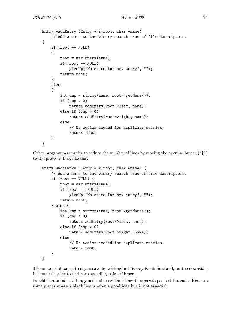
SOEN 341/4 S Winter 2000 75
Entry *addEntry (Entry * & root, char *name)// Add a name to the binary search tree of file descriptors.
{if (root == NULL){
root = new Entry(name);if (root == NULL)
giveUp("No space for new entry", "");return root;
}else{
int cmp = strcmp(name, root->getName());if (cmp < 0)
return addEntry(root->left, name);else if (cmp > 0)
return addEntry(root->right, name);else
// No action needed for duplicate entries.return root;
}}
Other programmers prefer to reduce the number of lines by moving the opening braces (“{”)to the previous line, like this:
Entry *addEntry (Entry * & root, char *name) {// Add a name to the binary search tree of file descriptors.if (root == NULL) {
root = new Entry(name);if (root == NULL)
giveUp("No space for new entry", "");return root;
} else {int cmp = strcmp(name, root->getName());if (cmp < 0)
return addEntry(root->left, name);else if (cmp > 0)
return addEntry(root->right, name);else
// No action needed for duplicate entries.return root;
}}
The amount of paper that you save by writing in this way is minimal and, on the downside,it is much harder to find corresponding pairs of braces.
In addition to indentation, you should use blank lines to separate parts of the code. Here aresome places where a blank line is often a good idea but is not essential:
SOEN 341/4 S Winter 2000 76
• between method declarations in a class declaration;
• between variable declarations in a class declaration;
• between major sections of a complicated function.
Here are some places where some white space is essential. Put one or more blank lines between:
• public, protected, and private sections of a class declaration;
• class declarations (if you have more than one class declaration in a file, which is notusually a good idea);
• function and method declarations.
9.2.2 Naming Conventions
Various kinds of name occur within a program:
• constants;
• types;
• local variables;
• attributes (data members);
• functions;
• methods (member functions).
It is easier to understand a program if you can guess the kind of a name without having tolook for its declaration which may be far away or even in a different file. There are variousconventions for names. You can use:
• one of the conventions described here;
• your own convention;
• your employer’s convention.
You may not have an option: some employers require their programmers to follow the companystyle even if it is not a good style.
As a general rule, the length of a name should depend on its scope. Names that are usedpervasively in a program, such as global constants, must have long descriptive names. Aname that has a small scope, such as the index variable of a one-line for statement, can beshort: one letter is often sufficient.
Another rule that is used by almost all C++ programmers is that constant names are writtenwith upper case letters and may include underscores.

SOEN 341/4 S Winter 2000 77
9.2.3 Brown University Conventions
Brown University has a set of coding standards used for introductory software engineeringcourses. Most of the conventions are reasonable, but you can invent your own variations. Hereare some of the key points of the “Brown Standard”, with my (P.G.) comments in [squarebrackets]:
• File names use lower case characters only.
UNIX systems distinguish cases in file names: mailbox.h and MailBox.h are differentfiles. One way to avoid mistakes is to lower case letters only in file names.
Windows does not distinguish letter case in file names. This can cause problems whenyou move source code from one system to another. If you use lower case letters consis-tently, you should not have too many problems moving code between systems. Note,however, that some Windows programs generate default extensions that have upper caseletters!
• Types and classes start with the project name.
An abbreviated project name is allowed. For example, if you are working on a projectcalled MagicMysteryTour, you could abbreviate it to MMT and use this string as a prefixto all type and class names: MMTInteger, MMTUserInterface, and so on.
[I don’t think this is necessary for projects. The components of a project are usually
contained within a single directory, or tree of directories, and this is sufficient indicationof ownership. The situation is different for a library, because it must be possible toimport library components without name collisions.]
• Methods start with a lower case letter and use upper case letters to separate words.Examples: getScore, isLunchTime.
[I use this notation for both methods and attributes (see below). In the code, youcan usually distinguish methods and attributes because method names are followed by
parentheses.]
• Attributes start with a lower case letter and use underscores to separate words. Exam-ples: start time, current task.
• Class constants use upper case letters with underscores between words. Examples:MAXIMUM TEMPERATURE, MAIN WINDOW WIDTH.
• Global names are prefixed with the project name. Example: MMTstandardDeviation.
[I use the same convention for methods and global functions. When a method is usedin its own class, this can lead to ambiguity. In many cases, however, you can recog-
nize methods because they appear as o.method() or p->method(). My rule for globalvariables is avoid them.]
• Local variables are written entirely in lower case without underscore. Examples: index,nextitem.
Whatever convention you use, it is helpful to distinguish attributes from other variables. InLarge-Scale C++ Software Design, John Lakos suggests prefixing all attributes with d . Thishas several advantages; one of them is that it becomes easy to write constructors withouthaving to invent silly variations. For example:

SOEN 341/4 S Winter 2000 78
Clock::Clock (int hours, int minutes, int seconds){
d_hours = hours;d_minutes = minutes;d_seconds = seconds;
}
9.2.4 Hungarian Notation
Hungarian notation was introduced at Microsoft during the development of OS/2. It is called“Hungarian” because its inventor, Charles Simonyi, is Hungarian. Also, identifiers that usethis convention are hard to pronounce, like Hungarian words (if you are not Hungarian, thatis).
If you do any programming in the Windows environment, you will find it almost essentialto learn Hungarian notation. Even if you have no intention of ever doing any Windowsprogramming, you should consider adopting this convention, because it is quite effective.
Hungarian variable names start with a small number of lower case letters that identify thetype of the variable. These letters are followed by a descriptive name that uses an upper caseletter at the beginning of each word.
For example, a Windows programmer knows that the variable lpszMessage contains a long pto a string terminated with a zero byte. The name suggests that the string contains a messageof some kind.
The following table shows some commonly used Hungarian prefixes.
c character
by unsigned char or byte
n short integer (usually 16 bits)
i integer (usually 32 bits)
x, y integer coordinate
cx, cy integer used as length (“count”) in X or Y direction
b boolean
f flag (equivalent to boolean)
w word (unsigned short integer)
l long integer
dw double word (unsigned long integer)
fn function
s string
sz zero-terminated string
h handle (for Windows programming)
p pointer

SOEN 341/4 S Winter 2000 79
9.2.5 Commenting Conventions
Comments are an essential part of a program but you should not over use them. The followingrule will help you to avoid comments:
Comments should not provide information that can be easily inferred from the code.
There are two ways of applying this rule.
• Use it to eliminate pointless comments:
counter++; // Increment counter.
// Loop through all values of index.for (index = 0; index < MAXINDEX; index++){ .... }
• Use it to improve existing code. When there is a comment in your code that is notpointless, ask yourself “How can I change the code so that this comment becomes point-less?”
You can often improve variable declarations by applying this rule. Change
int np; // Number of pixels counted.int flag; // 1 if there is more input, otherwise 0.int state; // 0 = closed, 1 = ajar, 2 = open.double xcm; // X-coordinate of centre of mass.double ycm; // Y-coordinate of centre of mass.
to
int pixelCount;bool moreInput;enum { CLOSED, AJAR, OPEN } doorStatus;Point massCentre;
There should usually be a comment of some kind at the following places:
• At the beginning of each file (header or implementation), there should be a commentgiving the project that the file belongs to and the purpose of this file.
• Each class declaration should have a comment explaining what the class is for. It isoften better to describe an instance rather than the class itself:
class ChessPiece{
// An instance of this class is a chess piece that has a position,// has a colour, and can move in a particular way.
....

SOEN 341/4 S Winter 2000 80
• Each method or function should have comments explaining what it does and how itworks.
In many cases, it is best to put a comment explaining what the function does in theheader file or class declaration and a different comment explaining how the functionworks with the implementation. This is because the header file will often be read by aclient but the implementation file should be read only by the owner. For example:
class MathLibrary{public:
// Return square root of x.double sqrt (double x);....
};
MathLibrary::sqrt (double x){
// Use Newton-Raphson method to compute square root of x.....
}
• Each constant and variable should have a comment explaining its role unless its namemakes its purpose obvious.
9.2.6 Block Comments
You can use “block comments” at significant places in the code: for example, at the beginningof a file. Here is an example of a block comment:
/***************************************//* *//* The Orbiting Menagerie *//* Author: Peter Grogono *//* Date: 24 May 1984 *//* (c) Peter Grogono *//* *//***************************************/
Problems with block comments include:
• they take time to write;
• they take time to maintain;
• they become ugly if they are not maintained properly (alignment is lost, etc.);
• they take up a lot of space.
Nevertheless, if you like block comments and have the patience to write them, they effectivelyhighlight important divisions in the code.
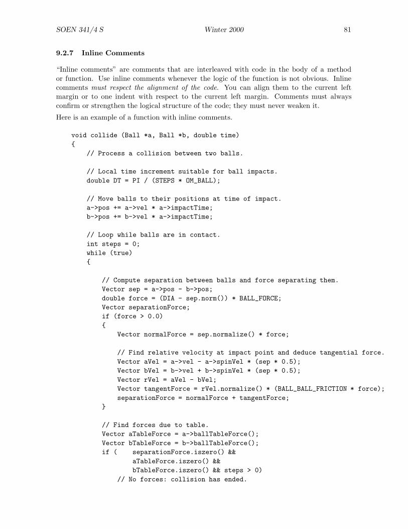
SOEN 341/4 S Winter 2000 81
9.2.7 Inline Comments
“Inline comments” are comments that are interleaved with code in the body of a methodor function. Use inline comments whenever the logic of the function is not obvious. Inlinecomments must respect the alignment of the code. You can align them to the current leftmargin or to one indent with respect to the current left margin. Comments must alwaysconfirm or strengthen the logical structure of the code; they must never weaken it.
Here is an example of a function with inline comments.
void collide (Ball *a, Ball *b, double time){
// Process a collision between two balls.
// Local time increment suitable for ball impacts.double DT = PI / (STEPS * OM_BALL);
// Move balls to their positions at time of impact.a->pos += a->vel * a->impactTime;b->pos += b->vel * a->impactTime;
// Loop while balls are in contact.int steps = 0;while (true){
// Compute separation between balls and force separating them.Vector sep = a->pos - b->pos;double force = (DIA - sep.norm()) * BALL_FORCE;Vector separationForce;if (force > 0.0){
Vector normalForce = sep.normalize() * force;
// Find relative velocity at impact point and deduce tangential force.Vector aVel = a->vel - a->spinVel * (sep * 0.5);Vector bVel = b->vel + b->spinVel * (sep * 0.5);Vector rVel = aVel - bVel;Vector tangentForce = rVel.normalize() * (BALL_BALL_FRICTION * force);separationForce = normalForce + tangentForce;
}
// Find forces due to table.Vector aTableForce = a->ballTableForce();Vector bTableForce = b->ballTableForce();if ( separationForce.iszero() &&
aTableForce.iszero() &&bTableForce.iszero() && steps > 0)
// No forces: collision has ended.
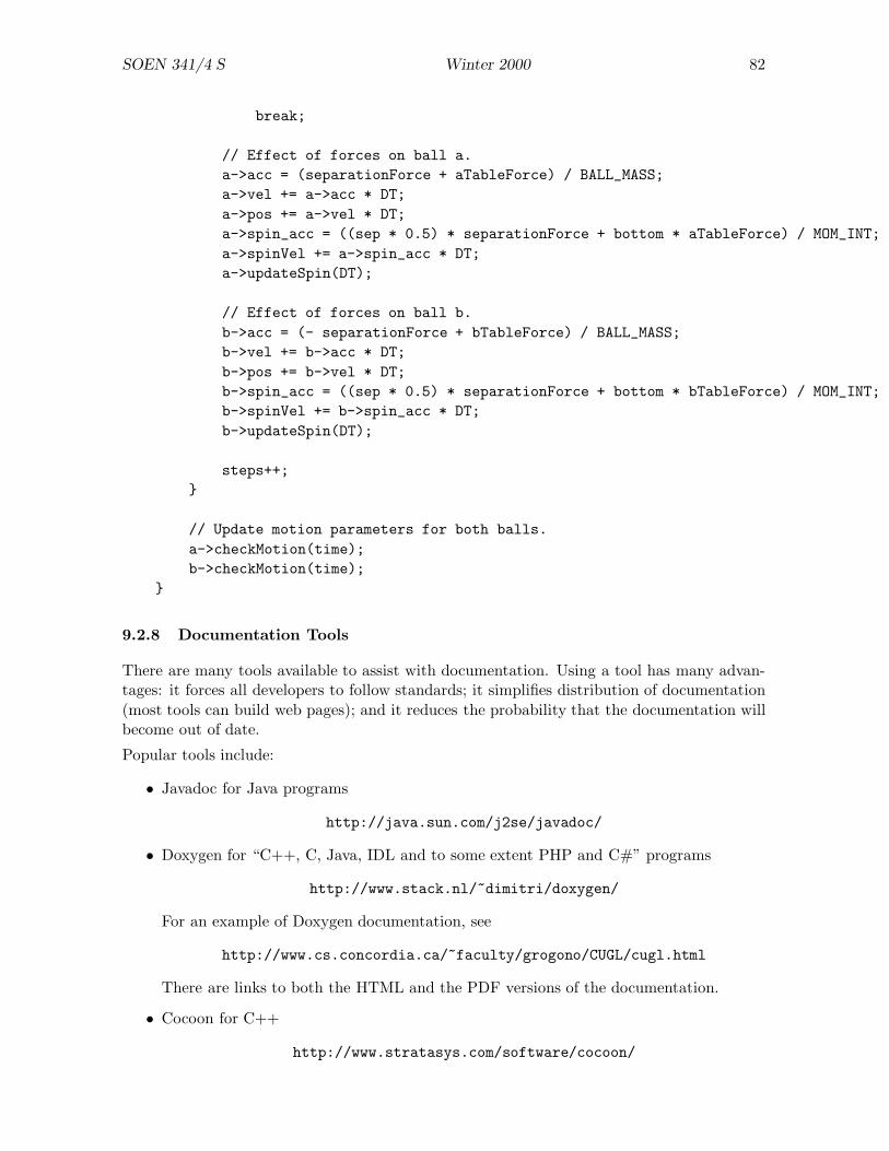
SOEN 341/4 S Winter 2000 82
break;
// Effect of forces on ball a.a->acc = (separationForce + aTableForce) / BALL_MASS;a->vel += a->acc * DT;a->pos += a->vel * DT;a->spin_acc = ((sep * 0.5) * separationForce + bottom * aTableForce) / MOM_INT;a->spinVel += a->spin_acc * DT;a->updateSpin(DT);
// Effect of forces on ball b.b->acc = (- separationForce + bTableForce) / BALL_MASS;b->vel += b->acc * DT;b->pos += b->vel * DT;b->spin_acc = ((sep * 0.5) * separationForce + bottom * bTableForce) / MOM_INT;b->spinVel += b->spin_acc * DT;b->updateSpin(DT);
steps++;}
// Update motion parameters for both balls.a->checkMotion(time);b->checkMotion(time);
}
9.2.8 Documentation Tools
There are many tools available to assist with documentation. Using a tool has many advan-tages: it forces all developers to follow standards; it simplifies distribution of documentation(most tools can build web pages); and it reduces the probability that the documentation willbecome out of date.
Popular tools include:
• Javadoc for Java programs
http://java.sun.com/j2se/javadoc/
• Doxygen for “C++, C, Java, IDL and to some extent PHP and C#” programs
http://www.stack.nl/~dimitri/doxygen/
For an example of Doxygen documentation, see
http://www.cs.concordia.ca/~faculty/grogono/CUGL/cugl.html
There are links to both the HTML and the PDF versions of the documentation.
• Cocoon for C++
http://www.stratasys.com/software/cocoon/

SOEN 341/4 S Winter 2000 83
9.2.9 Standard Types
Type representations vary between C++ implementations. For example, the type int may berepresented as 16, 32, or 64 bits. Consequently, it is common practice for experienced C++programmers to define a set of types for a program and use them throughout the program.Here is one such set:
typedef int Integer;
typedef char Boolean;
typedef char Character;
typedef double Float;
typedef char * Text;
typedef const char * ConstText;
To see why this is helpful, consider the following scenario. Programmer A develops a programusing these types for a system with 64-bit integers. The program requires integer valuesgreater than 232. Programmer B is asked to modify the source code so that the program willrun on processors for which int is represented by 32-bit integers. Programmer B changes oneline
typedef long Integer;
and recompiles the program. Everything will work, provided that long is implemented using64-bits. (If it isn’t, B can type long long instead.)
Other applications include: a programmer using an up to date compiler can redefine Booleanas bool (which is included in the C++ Standard); and can redefine Text to allow unicodecharacters.
The need for typedef statements is perhaps less than it used to be, because there is lessvariation between architectures than there used to be. With the final demise of DOS and itssegmented address space, most processors provide 32-bit integers and pointers. The distinctionbetween 16 and 32 bits was important because 216 = 65, 536 is not a large number. Thedistinction between 32 and 64 bits is less important since 232 = 4, 294, 967, 296 is large enoughfor many purposes. Since the introduction of bool (and the constants true and false), itis not really necessary to define Boolean. Nevertheless, you may wish to use typedefs toimprove the portability of your code.

SOEN 341/4 S Winter 2000 84
10 Testing
We want to avoid software failure. There are many different ways in which software may fail.
• A requirement was omitted.
Example: the client loses a master file and complains that the program should havemaintained backups of important files automatically. This is a serious “failure” fromthe client’s point of view but we cannot blame the software product for the failurebecause there was no requirement for automatic backups.
• The requirements were unimplementable.
Example: the client complains that the system is so busy with housekeeping that it nevergets any work done. Investigation shows that both hardware and software are performingcorrectly, but the hardware configuration is inadequate for the client’s needs.
• The specification was incorrect.
Example: a student logs in to the University’s Student Information System and requestsher grade for a non-existent course; the system crashes because the specification statedthat a course number consisted of four letters and three digits and defined no furthervalidation.
• There was an error in the high-level design.
Example: The component for remote access must be linked to the client database inorder to validate customers who access the system by telephone. Since the link wasomitted in the high-level design, the people working on the detailed design did notnotice the need for validation.
• There was an error in the detailed design.
Example: the specification required unique keys for a database but the design did notenforce uniqueness. The program was implemented according to the design but doesnot meet its specification.
• There was an error in the code.
Example: the design states that no action is to be performed if a certain pointer is NULL.The programmer omitted the test for NULL and the program crashed when it attemptedto dereference the pointer.
Here is the official terminology:
• In each of the examples above, a fault causes a failure.
• The process of discovering what caused a failure is called fault identification.
• The process of ensuring that the failure does not happen again is called fault correctionor fault removal.
“Bug” is a popular term for “fault”. There is a story to the effect that the first hardwarefailure was caused by a bug that was trapped between relay contacts in an early computer.This story is almost certainly mythical, because engineers were using the word “bug” before
SOEN 341/4 S Winter 2000 85
any computers had been built. But the usage is important: the word “bug” suggests thatfaults wander into the code from some external source and that they are therefore randomoccurrences beyond the programmer’s control. This is not possible for software: if your codehas faults, it is because you put them there.
We have seen that faults can exist in requirements, specifications, and designs. We have alsoseen ways of avoiding such faults (e.g., code review). This section is concerned mainly withfaults in the code.
There are essentially two ways of ensuring that the number of faults in code is small or —ideally — zero. One is to prove that the code has no faults and the other is to perform testsdesigned to find faults. Much effort has been put into proof techniques for programs, but theresulting systems are not widely used in industry. (The main exception is in the UK, wherethere are legal requirements for certification for certain kinds of critical application.)
Consequently, the main technique for fault detection is testing. Dijkstra has said: testingcan reveal only the presence of faults, never their absence . In other words, you cannever be certain that your program contains no faults but, with sufficient testing, you can beconfident that the number of remaining faults is acceptably small.
10.1 Coding Errors
There are many kinds of fault that can exist in code; some of them are listed below.
Syntax Errors. Most syntax errors are detected by the compiler, but a few are not. (Somepeople would argue that all syntax errors are caught by the compiler by definition, andthat a compiled program therefore cannot contain syntax errors.) However, a declarationsuch as
char* p, q;
is best classified as a syntax error (if q is meant to be a pointer) but the compiler doesnot report it.
Algorithmic Errors. A method does not execute according to its specification because thereis an error in the coding logic. Some common causes are:
• incorrect initialization;
• “off by one” error (example: starting at 1 rather than 0, stopping at N rather thanN − 1);
• incorrect condition (example: forgetting de Morgan’s laws);
• misspelling a variable name; type errors that remain undetected in the presence ofimplicit conversion.
Precision Errors. These arise when a programmer uses an int where a long was needed,or a float where a double was needed. Precision errors can also occur as the resultof implicit conversions. A common example is expecting 2/3 to evaluate to 0.666667rather than 0 (note that the operands might be variables rather than integer literals).
SOEN 341/4 S Winter 2000 86
Documentation Errors. The comments and accompanying code are inconsistent with oneanother. If the code is correct, there is not actually a fault. However, there is astrong likelihood of a fault being introduced later by a programmer who believes thedocumentation rather than the code.
Stress Errors. These are faults that occur when the system is stretched beyond its designedlimits. For example, a simple operating system that had an array of size N for activeusers might fail when user N +1 tries to log in. Two kinds of failure are possible: if thenew user is refused but the system continues to run, it is a soft failure; if the systemcrashes, it is a hard failure.
Capacity Errors. A word processor is required to handle documents up to 2 Gb in size butits performance is unacceptably slow for documents over 1 Mb.
Timing Errors. A system with multiple processes or threads fails occasionally because twoevents occur in the wrong order or simultaneously. Errors of this kind are very hard todiagnose.
Performance Errors. The requirements state that the system must respond in less than1 second but in fact the response to some kinds of query is more than 10 seconds.
Recovery Errors. The system is “fault tolerant”: that is, it is supposed to detect certainkinds of failure and recover gracefully. A failure to recover from an anticipated failureis a “recovery error”.
Hardware Errors. Hardware errors are usually, but not necessarily, beyond the program-mer’s control. However, safety-critical systems may anticipate hardware failures and,when such a failure occurs, handle it by switching to a stand-by system, for example.
Error of Omission. Something which should be present is not. For example, a variable hasnot been initialized.
Error of Commission. Something that should not be present is. For example, an exceptionhandler for a low-level failure is included when handling should have been delegated toa higher level component of the system.
10.2 Fault Classification
Various groups, mostly industrial, have attempted to classify faults. Appropriate fault classi-fication, combined with systematic detection and recording of faults, can provide insight intothe strengths and weaknesses of the software development process.
The Orthogonal Defect Classification system (Table 7.1, page 282), developed at IBM, hasthe following categories of defect (defect ≡ fault):
• function;
• interface;
• checking/validation;
• assignment/initialization;
SOEN 341/4 S Winter 2000 87
• timing/serialization;
• build/package/merge (repositories, version control);
• documentation;
• algorithm.
Hewlett-Packard have another fault classification system (Pfleeger, Figure 7.1, page 283) thatthey use for “profiling” problems within divisions of the company. Here are the results forone division (see also Figure 7.2, page 284):
Fault Category Occurrence (%)
Logic 32
Documentation 19
Computation 18
Other code 11
Data handling 6
Requirements 5
Process/interprocess 5
Hardware 4
10.3 Varieties of Testing
There are various ways to detect faults: reviews are important but, at some stage, it is usuallynecessary to resort to testing.
A simple definition of testing: execute the system (or one of its components) and comparethe results with anticipated results.
The “anticipated results” are the results predicted by the requirements if we are testing thewhole system. It may be harder to pin down the anticipated results when we are testingcomponents but, in general, they should be predicted by the design documents.
There are various kinds of testing; not all of the kinds listed below would be needed in smallor medium scale projects.
Unit Testing. (Also called module testing or component testing.) We test a compo-nent of the system in isolation. The component will expect inputs from other systemcomponents and will generate outputs that are sent to other components. For unit test-ing, we must construct an environment for the component that provides suitable inputsand records the generated outputs.
Integration Testing. We test all of the components of the system together to ensure thatthe system as a whole “works” (that is, compiles and doesn’t crash too often).
Function Testing. Assuming that the system “works” , we test its functions in detail, usingthe requirements as a basis for test design.

SOEN 341/4 S Winter 2000 88
Performance Testing. We measure the system’s speed, memory and disk usage, etc., toconfirm that it meets performance requirements.
Acceptance Testing. The previous tests are usually performed by the suppliers. When thesuppliers believe the software is ready for delivery, they invite the clients in to confirmthat they accept the software.
Installation Testing. When the clients have accepted the software, it is installed at theirsite (or sites) and tested again.
10.4 Testing Teams
When you test your own code, it is tempting to be “friendly” to it. After all, you don’t wantyour nice, new program to crash and, partly subconsciously, you will avoid giving it test datathat might make it crash.
This is the wrong attitude! A tester should be as nasty to the code as possible. The goal oftesting is to make the software fail.
It follows that programmers are not the best people to test their own code. It is better toassemble a separate testing team of people who have no interest in the code and who getrewarded for smashing it.
Programmers don’t like people who smash their code. It is important to develop psychologicalhabits that avoid “blaming” developers for errors in their code. The viewpoint that everyoneshould adopt is: “we all want the system to work as well as possible and we will all do what wecan to remove errors from it”. This attitude is sometimes called (following Gerald Weinberg)egoless programming.
Random tests are not very useful. The first task of the testing team is to design a battery oftests.
There is an important distinction between black box testing and white box testing. The termscome from electrical engineering; instead of “white” box, we can also so “clear” or “open”box.
Black box testing tests the component without making use of any knowledge of how itworks.
Clear box testing tests the component using information about how it works.
Suppose that you are testing a function
double sin (double x);
that is supposed to compute the trigonometric function sin x for given real values of x.
You execute the function with various arguments and check the results against a table oftrigonometric functions. This is black box testing.
Now suppose that you look at the body of the function and find something like Figure 14 (or,hopefully, something more efficient). The code suggests various tests: x < 0, x > 0, x < 2π,x > 2π, x < π
2 , x > π2 , x < 10−6, and x > 10−6, as well as tests at the boundaries: x = 0,
x = 2π, x = π2 , x = 10−6, and x > 10−6. This is clear box testing.
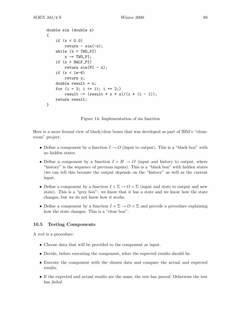
SOEN 341/4 S Winter 2000 89
double sin (double x){
if (x < 0.0)return - sin(-x);
while (x > TWO_PI)x -= TWO_PI;
if (x > HALF_PI)return sin(PI - x);
if (x < 1e-6)return x;
double result = x;for (i = 3; i <= 11; i += 2;)
result -= (result * x * x)/(i * (i - 1));return result;
}
Figure 14: Implementation of sin function
Here is a more formal view of black/clear boxes that was developed as part of IBM’s “clean-room” project.
• Define a component by a function I → O (input to output). This is a “black box” withno hidden states.
• Define a component by a function I × H → O (input and history to output, where“history” is the sequence of previous inputs). This is a “black box” with hidden states(we can tell this because the output depends on the “history” as well as the currentinput.
• Define a component by a function I × Σ → O × Σ (input and state to output and newstate). This is a “grey box”: we know that it has a state and we know how the statechanges, but we do not know how it works.
• Define a component by a function I × Σ → O × Σ and provide a procedure explaininghow the state changes. This is a “clear box”.
10.5 Testing Components
A test is a procedure:
• Choose data that will be provided to the component as input.
• Decide, before executing the component, what the expected results should be.
• Execute the component with the chosen data and compare the actual and expectedresults.
• If the expected and actual results are the same, the test has passed. Otherwise the testhas failed.
SOEN 341/4 S Winter 2000 90
A test set is a collection of tests.
Regression testing on a test set is carried out as follows:
• Perform tests from the test set one after another.
• When a test fails, stop testing and wait until the fault has been corrected.
• Start the tests again from the beginning.
The definitions given above must be adapted to the circumstances.
• Inputs may consist of keystrokes, mouse movements and clicks, and other events, insteadof just “data”. Tests should specify exactly what events will occur and in what order.Tests may even specify timing (“the left mouse button is clicked twice with less than0.5 seconds between clicks”).
• Outputs may appear in many forms: a window is created, destroyed, or turned grey; apopup menu appears; a list of files is displayed; etc.
Regression testing can become very tedious if a test set contains many tests that require useractions:
Test 23.4: Help functions.
• Move the cursor to the Help icon.• Click the left mouse button once. A popup menu opens.• Move the cursor to the Contents box.• Click the left mouse button once.• ....
A test set should be a comprehensive collection of specific tests for the software component.Testing is generally more effective if information about the implementation is used — that is,it is at least partially “white box”.
• Include valid data: data that the component is supposed to process and for which theexpected results are known.
• Include invalid data: data that the component is not supposed to process.
• Include boundary cases. For example, if a table is supposed to store up to 20 items, testit with (at least) 0, 19, 20, and 21 items.
The coverage of a test set is the code that will be exercised by performing all the tests in thetest set.
• Statement testing ensures that all statements are executed.
• Branch testing ensures that, wherever there is a “branch point” (if or switch state-ment), each branch is executed in at least one test.
• Path testing executes each path in the component (considered as a directed graph).
There are other, more elaborate possibilities. For example, we can ensure that each defini-tion/use pair is tested.
SOEN 341/4 S Winter 2000 91
10.6 Integration Testing
When components have been tested, they can be incorporated into the growing system. In-tegration testing means testing a group of components together. There are various ways inwhich integration testing can be carried out:
Bottom-up Integration. First test the components Cn that don’t use any other compo-nents; then test the components Cn−1 that use the components Cn but no others; andso on.
In bottom-up integration, the components that a component uses have already beentested and can be used in the test on the assumption that they work correctly. How-ever, we will need to build drivers to call the components, because the code that willeventually call them has not yet been tested. Drivers are written as simply as possiblebut should realistically exercise the components under test.
Top-down Testing. First test the components C0 that are not called by any other compo-nents; then test the components C1 that are called by components C0; and so on.
In top-down integration, the components that call the component under test can beused on the assumption that they work correctly. However, we will need to build stubsthat simulate the components called by the component under test. Stubs are writtenas simply as possible: they respond to all reasonable requests but return very simpleresults.
Big-Bang Integration. First test the components individually, then link all the componentstogether, click Run, and see what happens (usually the system crashes immediately). Forsystems of any complexity, big-bang integration is unlikely to be efficient. The problemis that, when failures occur, it is hard to figure out what caused them.
Sandwich Integration. This is a combination of top-down and bottom-up, the objectivebeing to converge on a layer in the “middle” of the system for which higher and lowercomponents have already been tested. The following advantages are claimed for sand-wich testing:
• Integration testing can start early in the testing process, because groups of com-ponents can be tested.
• Top-level components (control) and bottom-level components (utilities) are bothtested early.
It is interesting to note that we can perform neither pure bottom-up nor pure top-downintegration testing if there are cycles in the dependency graph. If components C1, C2, . . . , Cn
for a cycle, we are forced to test all of the simultaneously. This is a very good reason to avoidcycles in the component dependency graph!
The key points for integration testing are:
• Each component should be tested exactly once.
• A single test should involve as few components as possible, preferably one.
• A component should never be modified for the purpose of testing.

SOEN 341/4 S Winter 2000 92
• It will usually be necessary to write additional code (stubs, drivers, etc.) specifically fortesting. It is a good idea to keep this code so that it can be used for testing improvedversions of the system after release.
10.7 Testing Object Oriented Code
A high proportion of new code is object oriented. As such, it presents a few special problemsfor testing.
• Testing classes individually is difficult in the presence of inheritance.
Suppose that a parent class P has children C1, C2, . . .. Then methods in Ci may invokemethods in P . If an error in Ci is caused by an error in P , correcting the error in Pmay break code in Cj (i 6= j).
• Dynamic binding can also make testing harder. A statement of the form p->f() mayinvoke different methods each time it is called, depending on the classs of *p.
Although OO code has special problems, it should also have certain advantages with respectto testing. In particular, if classes respect encapsulation, it should be possible to test themindependently of classes that use them (although not classes that they use).
10.8 Testing Strategies
Testing should always proceed according to a predefined plan rather than in an ad hoc fashion.(Ad hoc testing produces odd hacks.)
A test plan consists of a collection of tests and a strategy for applying them.
• The plan should describe what happens if a test fails. Usually, the failure is noted andtests proceed. However, if the test is a particularly significant one, testing may have tobe delayed until the fault is corrected. For example, if the system fails on startup, thetesting team have to wait until the problem is fixed.
• The plan should describe what happens when the faults revealed by tests have beencorrected. A common strategy is called regression testing . Assume that the tests arenumbered 1, 2, 3, . . . and that test n fails. After the fault has been corrected, regressiontesting requires that tests 1, 2, . . . , n must all be repeated.
Regression testing takes a long time. If possible it should be automated (see below).Otherwise, a careful analysis should be performed to see if all of the previous tests mustbe repeated or whether some of them are, in some sense, independent of test n.
• Test results must be carefully recorded.
Automation. If possible, testing should be automated . This requires a program that can:
• invoke the component under test with suitable test data;
• observe the effect of the test;
• decide whether to stop or continue, depending on the results for the test.
SOEN 341/4 S Winter 2000 93
Automatic testing is fairly straightforward if we are dealing with functions that accept pareme-ters and return results. It is more complicated if we are testing, for example, a windows-basedapplication. However, there are testing tools that will record a sequence of events (keystrokes,mouse movements, etc.) and “play them back” during testing.
Although it is not strictly “testing”, software tools can be used to check code both staticallyand dynamically.
• Static analyzers check that variables are initialized before they are used, that all state-ments can be reached, that components are linked in appropriate ways, etc. Compilesrperform some static analysis, of course, but they tend to be better at within-componentanalysis than at between-component analysis.
• Test case generators analyze the source code a generate tests based on it. Thesetools can ensure, for example, that there are tests for each branch of every conditionstatements. Of course, if the code contains errors, a test case generator may generateinappropriate tests.
• Dynamic analyzers make measurements while the code is running. They can col-lect statistics about the frequency of execution of various blocks and look for potentialsynchronization problems in concurrent processes.
• Capture and replay tools record a sequence of user actions and can play them backlater. User actions include keystrokes, mouse movements, and mouse clicks. Thesetools avoid the time-consuming and error-prone task of repeating a complicated seriesof actions whenever a test has to be run.
When do you stop testing? The testing strategy must include a criterion for terminatingtesting. Ideally, we would terminate testing when there are no faults left. In practice, thiswould mean testing for ever for most systems. We can make the following observations:
• Assuming that testing is continuous, the rate of fault detection is likely to fall.
• The accumulated cost of testing increases with time.
• The value of the product probably decreases with time (for example, competitors get tothe market).
At some time, there will be a break-even point where it is better to release the product withresidual faults than it is to continue testing. Of course, it is not always easy to decide exactlywhen the break-even point has been reached!
10.9 Avoid test failures: read your code
It is often more productive to read the code than to run tests on it. After you have observeda fault, you have to read the code anyway, to see what went wrong. Often, you can avoid theneed for debugging by spotting the error before running the tests. There are several ways ofreading code.

SOEN 341/4 S Winter 2000 94
Desk Checking. Get into the habit of reading code that you have just written before run-ning it. This often saves time because simple errors sometimes lead to very strangesymptoms.
Code Walkthrough. During a “walkthrough”, a programmer presents code to a small groupline by line, explaining the purpose of each line. Members of the group read the linesas they are presented to ensure that the code actually does what the presenter claims itdoes. It is important to place emphasis on the code itself, not on the person who wroteit. When people question features of the code, the programmer’s job is not to defendit but to admit that it is wrong or explain why it is correct although it appears to bewrong.
It is best not to attempt to correct errors during the walkthrough; the important thingis to identify errors for subsequent correction.
Code Inspection. Code inspection was introduced in 1976 at IBM by Mike Fagan. An in-spection is like a walkthrough in that code is studied carefully but an inspection involvesanother set of documents, which can be requirements, specifications, or designs. Thepurpose of the inspection is to check that the code does in fact meet the requirements,satisfy the specifications, or implement the designs. The people present include theoriginators of the documents as well as the implementors of the code.
Inspections are sometimes conducted as three-phase processes. There is a preliminarymeeting at which the goals of the inspection are identified. Then team members studythe code individually, noting any errors that they find. Finally, there is another meetingof the inspection team during which the errors are presented and discussed.
There has been a substantial amount of research into the effectiveness of code reviews. Mostof the results confirm that reading and inspecting code is more effective than debugging. Thatis, the number of faults identified for each person-hour spent is greater when the people areinspecting code than when they are debugging it.
10.10 Project Requirements
Your project should include a test plan and a test report .
• A minimal test plan should describe your testing strategy and outline the kind of testthat you will perform. A detailed test plan would include a list of all the tests that youintend to perform and the expected outcome of each test.
• The test report should describe the process of testing, the number of tests that passedand failed, and the action that you took in response to failed tests.
SOEN 341/4 S Winter 2000 95
11 System Testing
Until now, we have discussed program testing. Once the code is working, we can test thesystem as a whole.
In some cases, the code forms the major part of the system and, when program testingis complete, there is not much more to do. In the majority of cases, however, the codecomponent of a software engineering project is only one part of the total system.
System testing has much in common with program testing and there is no need to dwell onthe similarities. For example: faults in the system lead to failures ; the failures must beidentified and the corresponding faults corrected ; after correcting the faults, it is advisableto run regression tests to ensure that new faults have not been introduced.
Suppose that the product is flight-control software for a new kind of aircraft. The system isthe aircraft as a whole. Here is a simplified version of a possible test plan:
Function Testing. The software is thoroughly tested in an environment that simulates theaircraft. That is, the software is provided with inputs close to those that it would receivein actual flight, and it must respond with appropriate control signals.
When the function test results have been accepted, we have a functioning system .
Performance Testing. The so-called “non-functional requirements” of the software are thor-oughly tested. Does it respond within acceptable time limits? Are there any circum-stances in which available memory might be exhausted? Does it degrade gracefully whenthings go wrong? If there are duplicated subsystems, is control transferred between themwhen expected?
Performance tests are listed in the text book and will not be described in detail here.They include: stress, volume, configuration, compatibility, regression, security, timing,environment, quality, recovery, maintenance, documentation, and human factors (orusability) tests.
After performance testing, we have a verified system.
Acceptance Testing. The tests are run for the clients, still on simulated equipment. Ex-perienced pilots will “fly” the simulated aircraft and will practice unusual as well asstandard manouvres.
After acceptance testing, the clients agree that this is the system that they want. Thesystem is said to be validated .
Installation Testing. The software is installed on an actual aircraft and tested again. Thesetests are conducted slowly and carefully because of the consequences of an error. Severaldays may be spent during which the plane travels at less than 100 km/h on the runway.Then there will be short “flights” during which the plane gets a few metres off theground. Only when everyone is fully confident that flight can be controlled will the testpilot perform a true take-off and fly a short distance.
If installation testing goes well, the system is put into use. The maintenance phasebegins.

SOEN 341/4 S Winter 2000 96
11.1 Verification and Validation
The terms “verification” and “validation” are often bundled together as “V&V”. There is,however, a useful distinction that we can make between them:
Verifying the system is the process of ensuring that the software is internally consistent andthat all functions perform according to specifications. Informally, verification answersthe question: Have we built the system right?
Validating the system is the process of ensuring that the software meets the clients needs.Informally, verification answers the question: Have we built the right system?
11.2 Unique Aspects of System Testing
There are some aspects of system testing that are significantly different from program testing.These are discussed briefly here.
Configuration. The software may have to run in many different configurations. In the worstcase, each platform may be unique. Stu Feldman says that,in telecom software, it is notunusual to have several thousand makefiles for a system. All of these must be tested— on a common platform, if possible, but probably on the platform for which they areintended.
Versions. The word “version” is ambiguous because its informal meaning is that of laterversions replacing earlier versions. But it is also used in the sense of “version for platformA”, “version for platform B”, etc. Here, we will assume that each “version” is intendedfor a particular platform and application.
Releases. The word “release” is the formal term that corresponds to the informal use of “ver-sion”. The software is issued in a series of numbered releases , each of which is intendedto be an improvement on its predecessors. There is usually a distinction between majorreleases which incorporate significant enhancements and minor releases which cor-rect minor problems. Releases are numbered so that “Release 4.3” would be the thirdrevision of the fourth major release.
Production System. After the system has been released to clients, the developers mustkeep an identical copy so that they can check client’s complaints. This copy is calledthe “production system”.
Development System. In addition to the production system, the developers should main-tain a separate system into which they can incorporate corrections and improvements.At well-defined points, the “development system” is delivered to the clients, as a newrelease, and becomes the “production system”. At that time, a new development systemis started.
Deltas. Software systems can become very large; maintaining complete copies of all of thefiles of many different versions can require enormous amounts of storage and — moreimportantly, since storage is cheap — involve significant copying time. A solution is tomaintain one complete set of files for the entire system and, for each version, a set offiles that define the differences particular to the version. The difference files are called“deltas”.
SOEN 341/4 S Winter 2000 97
Use of deltas must be supported by an effective tool to manage them, otherwise disasterensues. There should be a simple and reliable way of combining the basic system fileswith a set of delta files to obtain a release.
A problem with deltas is that, if the base system is lost, all releases are lost as well. Thebase system must therefore be regarded as a document of great value.
The unix utility SCCS (Source Code Control System) uses deltas to maintain multipleversions of files.
11.3 Reliability, Availability, Maintainability
A system is reliable to the extent that it can operate without failure for a given time interval.The time is measured while the system is running, not while it is idle. A system that is requiredto run for 5 seconds a year, and always performs flawlessly for those 5 seconds, is entirelyreliable. Reliability is usually measured on a scale of 0 to 1 in which 0 means the system neveroperates and 1 means that it always operates.
A system is available to the extent that it is operating correctly when it is needed. If thesystem is currently running, it is available. If it is “down” for repairs, it is not available.Availability time is real time, not execution time.
A system is maintainable to the extent that, after a failure, it can be made to operate againwithin a given period of time with a given probability. Whereas hardware systems are usuallyunavailable during maintenance, there are an increasing number of software systems that arerequired to operate while they are being maintained.
We can quantify these ideas as follows. Assume for simplicity that the system is supposed tooperate continuously (for example, it might be software for a telephone switch). We measurethe time intervals between failures; the average of these times is the mean time to failureor MTTF.
When the system fails, we record the time taken to repair it and restore operations. Theaverage of these times is the mean time to repair or MTTR.
We define the mean time between failures as
MTBF = MTTF + MTTR
According to the text book:
Reliability =MTTF
1 + MTTF
Availability =MTBF
1 + MTBF
Maintainability =1
1 + MTTR
Note that:
• each of these parameters has a value between 0 and 1;
• the parameters are meaningless.
SOEN 341/4 S Winter 2000 98
Example: A system has MTTF = 4 days and MTTR = 20 minutes = 0.0138 days. If we usedays as the unit of time:
Reliability = 0.8Availability = 0.9863
But, if we use minutes as the unit of time:
Reliability = 0.9998Availability = 0.9998
The following is a more sophisticated analysis, adapted from pp. 622–3 of Software Engineer-ing: an Engineering Approach by Peters and Pedrycz (Wiley, 2000).12
Assume that the system has two states, up (i.e., operating correctly) and down (i.e., notoperating). Suppose that, during a time interval ∆t, the transition probabilities are:
up → down = λ ∆t
down → up = µ ∆t
This system has the following transition probability matrix : 1 − λ ∆t λ ∆t
µ ∆t 1 − µ ∆t
Suppose that pu(t) is the probability that the system is down at time t and pd(t) is theprobability that the system is up at time t. Then we can infer from the transition probabilitymatrix that:
pu(t)(1− λ ∆t) + pd(t)µ ∆t = pu(t + ∆t)pu(t)λ ∆t + pd(t)(1 − µ ∆t) = pd(t + ∆t)
We could solve this as a differential equation to obtain the dynamic behaviour of the system,but it is easier to obtain the steady state solution by putting ∆t = 0. This gives the sameequation twice:
−λpu + µpd = 0λpu − µpd = 0
However, we know from probability theory that pu + pd = 1. Thus we can deduce:
pu =µ
λ + µ
pd =λ
λ + µ
It seems reasonable to define availability as pu, since this is the probability that the systemis “up” at a given time.
12A good text book for this course — but for the fact that it costs about $140.

SOEN 341/4 S Winter 2000 99
t
R
Figure 15: Plot of reliability, R, as a function of time, t.
Example: Assume that the probability that a system will fail during a one hour run is 1%and that the probability of repairing it within an hour after failure is 90%.
Then λ = 0.01, µ = 0.9, and λ + µ = 0.91. We have pu = 0.9/0.91 = 0.989, so we can saythat the availability of the system is 98.9%.
11.4 Reliability during development
During the development, we (hopefully) remove defects from the software. Thus we canassume that the reliability improves. In general, we expect (Figure 15):
• The reliability is initially very low (close to zero), because most components will havefaults.
• The reliability improves monotonically during development, as faults are removed.
• The reliability tends asymptotically to 1.
As a consequence, we can say that the cost of testing (measured as the time required to detectand correct one fault) must increase (the fewer the faults, the harder they are to find).
As the reliability increases, the cost of releasing the software decreases. To see this, supposewe release the software at an early stage, when there are many faults. There will be numerouscomplaints from clients, and the developers will spend a lot of time attending to them. Evenworse, potential sales will fall as news of the unreliability spreads. Conversely, if we wait untilthe software is practically perfect before releasing it, there will be few complaints, and thecost of release will be low.
Now consider the total cost, the sum of the cost of testing and the cost of releasing, as afunction of time, t. For small t, it is high because of client complaints. For large t, it is largebecause tests are expensive. Therefore (as economists say), there must be a value of t forwhich the total cost is minimal; this is the best time to release the software: see Figure 16.
11.5 Testing with UPEDU
In this section, we review the UPEDU approach to testing. Not surprisingly, there is someoverlap between this section Section 10.
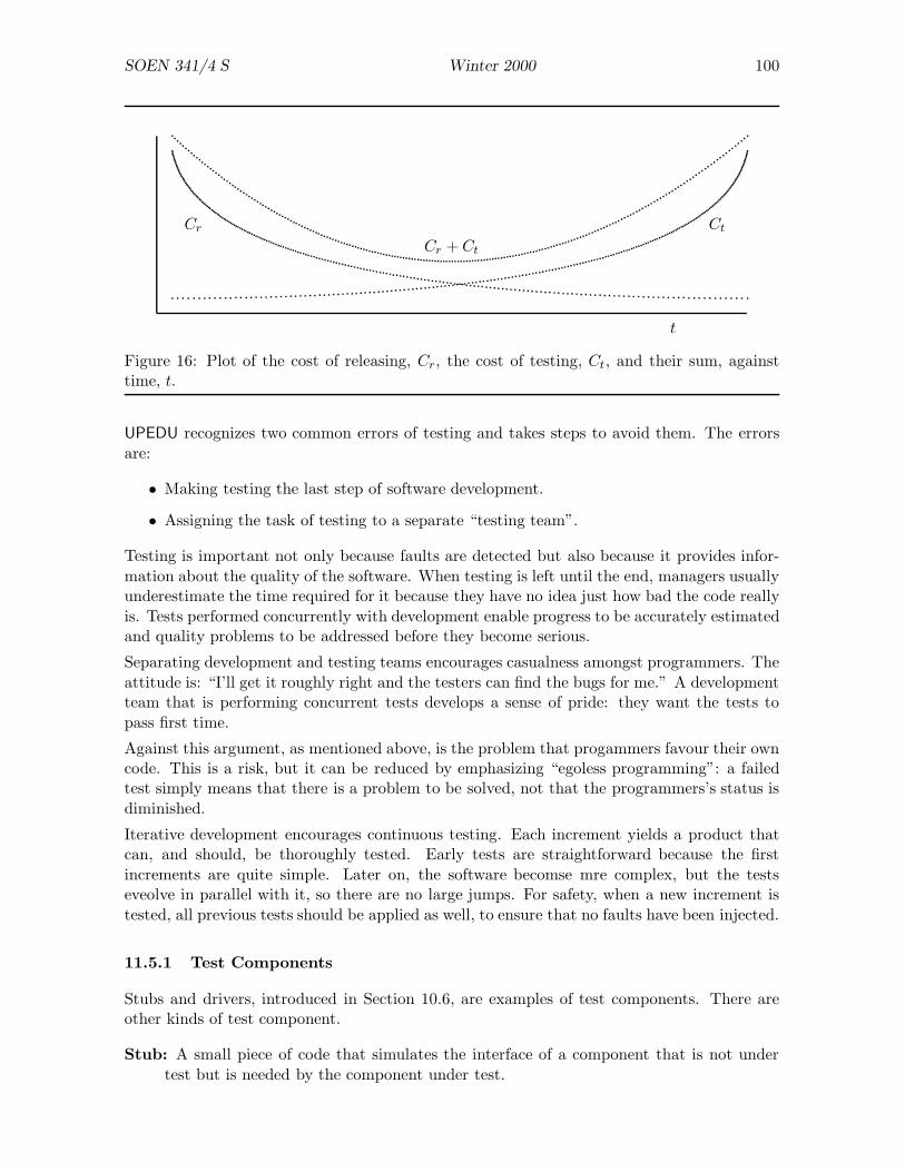
SOEN 341/4 S Winter 2000 100
t
Cr Ct
Cr + Ct
Figure 16: Plot of the cost of releasing, Cr, the cost of testing, Ct, and their sum, againsttime, t.
UPEDU recognizes two common errors of testing and takes steps to avoid them. The errorsare:
• Making testing the last step of software development.
• Assigning the task of testing to a separate “testing team”.
Testing is important not only because faults are detected but also because it provides infor-mation about the quality of the software. When testing is left until the end, managers usuallyunderestimate the time required for it because they have no idea just how bad the code reallyis. Tests performed concurrently with development enable progress to be accurately estimatedand quality problems to be addressed before they become serious.
Separating development and testing teams encourages casualness amongst programmers. Theattitude is: “I’ll get it roughly right and the testers can find the bugs for me.” A developmentteam that is performing concurrent tests develops a sense of pride: they want the tests topass first time.
Against this argument, as mentioned above, is the problem that progammers favour their owncode. This is a risk, but it can be reduced by emphasizing “egoless programming”: a failedtest simply means that there is a problem to be solved, not that the programmers’s status isdiminished.
Iterative development encourages continuous testing. Each increment yields a product thatcan, and should, be thoroughly tested. Early tests are straightforward because the firstincrements are quite simple. Later on, the software becomse mre complex, but the testseveolve in parallel with it, so there are no large jumps. For safety, when a new increment istested, all previous tests should be applied as well, to ensure that no faults have been injected.
11.5.1 Test Components
Stubs and drivers, introduced in Section 10.6, are examples of test components. There areother kinds of test component.
Stub: A small piece of code that simulates the interface of a component that is not undertest but is needed by the component under test.
SOEN 341/4 S Winter 2000 101
Driver: A small piece of code that simulates the users of the component under test byexercising its interface.
Zombie: A general term for a minimal driver or stub.
Throwaway: A small piece of code that is written to test a component once and then dis-carded.
Script: A script, or progam, usually written in a high-level language such as perl or Python,that runs a set of tests and reports the results.
Scaffolding: Any code that is written for the purpose of testing but does not become partof the final product.
Test components must be written very carefully. It can happen that a test succeeds but itis later found that both the test code and the system code were wrong. Test code should beas simple as possible to maximize the probability that it does not contain any errors. Whenvery complex and safety-critical systems are being tested, it may even be necessary to writetests for the test code!
11.5.2 Testing Activities
Testing Environment The first step in testing is to create a testing environmment . Insimpole cases, the testing environment might just be a PC on the tester’s desk. Even here, itis important to ensure that the PC is set up in the same way as the client’s PCs will be setup. Otherwise the tester may report satisfaction only to find that the client cannot run thesoftware because of missing DLLs, for example.
For more complex systems, the testing environment may be very complex. Testing flightcontrol software, for example, might require an expensive simulator. In the final stages, theactual aircraft would be needed.
Test Cases UPEDU associates test cases with use cases . Since a use case describes asingle transaction between a user and the system, it is natural to design tests to check thatsystem behaviour corresponds to use cases. In general, each use case will generate a numberof individual tests, depending on the possible paths and outcomes of the use case.
Use cases are only one part of the requirements. Other parts of the requirements may requirespecial testing.

SOEN 341/4 S Winter 2000 102
12 Delivery and Maintenance
12.1 Delivery
Although delivery is important in practice, we will not spend a lot of time on it in this course.The main point to note is that the delivery process depends strongly on the kind of system.
• “Shrink-wrap” software is delivered to customers through retail stores. The productmust be essentially self-contained because the suppliers cannot afford to spend timewith individual clients; the best they can do is provide some kind of assistance viainternet or telephone. This implies that: the software should be easy to install, learn,and use; and that all documentation, printed or on-line, comes with the package. Thecost of shrink-wrap software ranges from about $5 to $5 000.
• Above $5 000 or so, customers expect additional services. The suppliers may offer: helpwith installation; on-site acceptance tests; and training courses, at either their own orthe customer’s site.
• When the software is developed for an individual client, there will probably be a closerelationship between the supplier and the client. As we have seen, the client will beinvolved with the software from an early stage, such as requirements analysis. Deliverywill be just one step — albeit an important step — in the software development pro-cess. Delivery is not the last step; rather, it signals a transition from development tomaintenance.
Software will not be used unless its users understand it and are comfortable with it. “Shelfware”is the name give to software purchased, sometimes at considerable cost, and then never used.To avoid your product becoming shelfware:
• make the software as easy to use as possible;
• write clear and unambiguous user manuals;
• provide on-line help, where applicable;
• write all documentation from the point of view of the user rather than the programmer.
12.2 Maintenance
After software has been delivered, in whatever form, it must be maintained . Studies supportthe “80–20 rule”: over the entire lifespan of a software product, 20% of the effort is indevelopment and 80% is in maintenance.
12.2.1 Varieties of Maintenance
The word “maintenance” suggests lubricating your bicycle or taking an applicance to Mr FixItto have a part replaced. This kind of maintenance clearly does not apply to software, becausecode does not get stiff or wear out. Software maintenance is generally divided into fourvarieties.
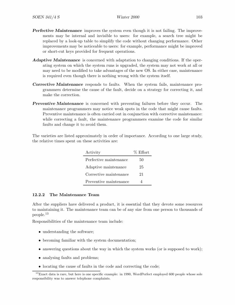
SOEN 341/4 S Winter 2000 103
Perfective Maintenance improves the system even though it is not failing. The improve-ments may be internal and invisible to users: for example, a search tree might bereplaced by a look-up table to simplify the code without changing performance. Otherimprovements may be noticeable to users: for example, performance might be improvedor short-cut keys provided for frequent operations.
Adaptive Maintenance is concerned with adaptation to changing conditions. If the oper-ating system on which the system runs is upgraded, the system may not work at all ormay need to be modified to take advantages of the new OS. In either case, maintenanceis required even though there is nothing wrong with the system itself.
Corrective Maintenance responds to faults. When the system fails, maintenance pro-grammers determine the cause of the fault, decide on a strategy for correcting it, andmake the correction.
Preventive Maintenance is concerned with preventing failures before they occur. Themaintenance programmers may notice weak spots in the code that might cause faults.Preventive maintenance is often carried out in conjunction with corrective maintenance:while correcting a fault, the maintenance programmers examine the code for similarfaults and change it to avoid them.
The varieties are listed approximately in order of importance. According to one large study,the relative times spent on these activities are:
Activity % Effort
Perfective maintenance 50
Adaptive maintenance 25
Corrective maintenance 21
Preventive maintenance 4
12.2.2 The Maintenance Team
After the suppliers have delivered a product, it is essential that they devote some resourcesto maintaining it. The maintenance team can be of any size from one person to thousands ofpeople.13
Responsibilities of the maintenance team include:
• understanding the software;
• becoming familiar with the system documentation;
• answering questions about the way in which the system works (or is supposed to work);
• analysing faults and problems;
• locating the cause of faults in the code and correcting the code;13Exact data is rare, but here is one specific example: in 1990, WordPerfect employed 600 people whose sole
responsibility was to answer telephone complaints.
SOEN 341/4 S Winter 2000 104
• keeping system documentation up to date (changes to code imply changes to documents);
• restructuring design documents and the corresponding code;
• deleting parts of documents and code that are no longer used;
• adapting existing functions to changing requirements;
• adding new functions;
• managing change.
There are many problems associated with maintenance. Here are brief discussions of a few ofthem.
Understanding the Software. One study showed that 47% of maintenance programmers’time is spent in understanding the software. This is a natural consequence of several factors:
• Most developers keep their “best” programmers for development, considering them tooimportant for maintenance. Consequently, maintenance programmers are usually nottop calibre.
• Newly-hired programmers are often given maintenance tasks before they are allowed towork on development.
• Developers are closely associated with the software for a long time and come to knowit well. Maintainers may be given a component with a problem and told to “fix it”. Itmay take them a long time to become familar with the overall structure of the system
Management. There is usually a lot of pressure from managers to get faults repaired rapidlyto please the client. Conscientious programmers who spend a lot of time analysing and tryingto understand the fault receive less praise than sloppy programmers who find a “quick fix”.As the quick fixes accumulate, the software becomes harder to understand and repair. Theshort-term policy of rapid repair has the long-term consequence of software that is “brittle”— it is poorly structured and breaks under the slightest strain.
Morale. Maintenance programmers often have a lower status than developers. This isunjustified because maintenance programming is in some ways harder than development pro-gramming. Nevertheless, the perception that the maintainers are “second tier” programmersis common and has the effect that every maintainer wants to be “promoted” to development.
The morale problem can be handled by a good manager who treats all programmers as equalsand who requires everyone to take turns at development and maintenance. This approach hasthe added advantage that doing maintenance gives the development programmers a betterunderstanding of the importance of clarity, simple solutions, and good documentation.
SOEN 341/4 S Winter 2000 105
Longevity. The long life of software creates maintenance problems. A large system may beused for 20 years or more. Moore’s Law says that hardware performance doubles about every18 months. During the 20–year lifespan of the software, the hardware that it runs on can beexpected to improve by a factor of 220/1.5 ≈ 10 000. Design decisions that seemed reasonableduring the initial development phase may look stupid in the light of such improvements.
The classic example of a longevity problem was the much-exaggerated “Y2K” problem, intro-duced by the decision to assign two digits rather than four digits to the “year” field in manyprograms. Performance, however, was not the major factor in the Y2K problem. The decisionto use two digits for the year was not made because memory was expensive but because itsimply did not occur to the designers that their code would still be running in 1999.
Managing Change. The maintenance team must know, at all times, the exact status ofeach component of the system. Each time there is a change request for any component, thesome or all of the following information should be recorded.
Synchronization: when is the change to be made?
Identification: who will make the change?
Naming : what components of the system are affected?
Authorization: who gave permission for the change to be made?
Cancellation: who can cancel the change request?
Routing : who will be informed of the change?
Delegation: who is responsible for the change after it has been made?
Valuation: what is the priority of the change?
Authentication: (after the change has been made) was the change made correctly?
12.2.3 Software Rejuvenation
The traditional approach to maintenance is that you maintain the system until it becomesunaminatainable — that is, the cost of keeping it running exceeds the benefit of running it.At this time, the system is scrapped and either rewritten from scratch or replaced by a newsystem designed to different requirements.
A more modern approach is to attempt to rejuvenate the software. If rejuvenation succeeds,the system becomes easier to maintain and its useful life can be extended. There are variousapproaches to rejuvenation, some simple and others more drastic.
Redocumentation: the system is analysed thoroughly and a new set of documents describingit is prepared. This does not improve the software in itself, but may make other formsof rejuventation feasible.
Reverse Engineering : the current design of the system is inferred from its code. This maybe necessary either because the original design documents have been lost or becausethe design has changed as a result of extensive maintenance. Software tools for reverseengineering exist.
SOEN 341/4 S Winter 2000 106
Reengineering : involves both reverse and “forward” engineering, first to discover how thesystem works and then to improve its structure without changing its functionality.
Restructuring : the code is modified in various ways to simplify maintenance. For example,very old FORTRAN programs are structured primarily with IF/GOTO statements becauseFORTRAN did not have WHILE/DO and IF/THEN/ELSE statements. The code can berewritten using the modern statements, either manually or (better) automatically.
Refactoring : the code is modified as in restructuring, but the changes tend to be larger.For example, related components may be merged, or functionality may be moved fromone component to another, more appropriate, component.
Paradigm Change: structured code may be rewritten in an object oriented way, or proce-dural code may be rewritten in a purely functional way.
SOEN 341/4 S Winter 2000 107
13 Case Studies
13.1 The Therac-25 Saga
There was a consortium consisting of Atomic Energy Canada Limited (AECL) and CGR,a French company. The consortium’s products included: Neptune; Sagittaire; Therac-6 (a6 MeV X-ray accelerator consisting of Neptune and a PDP/1114 controller); Therac-20 (a20 MeV dual-mode (X rays or electrons) accelerator consisting of Sagittaire and a PDP/11controller). All of these products were designed to administer controlled doses of radiation topeople with cancer.
The Therac-6 and Therac-20 could be operated without the computer. “Industry standardhardware safety features and interlocks” were retained in both machines. Software control wasadded for convenience; even if the software failed, operations would be restricted by hardware.
Around 1975, AECL developed the Therac-25 using “double pass” technology, in which theenergy source is a magnetron rather than a klystron and the acceleration path is folded soas to require less space. The Therac-25 generates electron or X ray beams at up to 25 MeV.High doses permit treatment at greater depth in the body.
Key points about the Therac-25 design:
• Therac-25 was controlled by a PDP/11.
• The software was an essential component of the system, not an optional add-on.
• Therac-25 relied on software correctness for safety: it did not have electrical and me-chanical interlocks like the Therac-6 and Therac-20.
• Some of the software from the Therac-6 and Therac-20 was reused.
The first prototype of Therac-25 was produced in 1976. A commercial version became availablein 1982. In March 1983 a safety analysis performed by AECL made these assumptions:
• Software errors had been extensively tested with a hardware simulator. Any residualerrors were not included in the analysis.
• Software does not degrade due to wear, fatigue, or reproduction.
• Computer execution errors are caused by faulty hardware and random errors inducedby alpha particles and electromagnetic noise.
The fault tree obtained from the analysis includes “computer failure”. The probability thatthe computer would select the wrong energy level was estimated to be 10−11. The probabilitythat the computer would select the wrong mode was estimated to be 10−9. The report providesno justification for these numbers and seems to imply that they arise from hardware failure,not software failure.
14The PDP/11 was an early minicomputer developed by Digital Equipment Corporation.

SOEN 341/4 S Winter 2000 108
13.1.1 Problems.
Five Therac-25s were installed in the USA and six in Canada. Between 1985 and 1987,there were six accidents involving radiation overdoses. The Therac-25s were recalled in 1987.Typical accidents:
• Patient: “You burned me”. Diagnosis revealed one or two doses of radiation in therange 15K to 20K rads. Typical doses are around 200 rads; 1K rads can be fatal. Thispatient did not die but required extensive surgery.
• The operator activated the Therac-25 but it shut down after 5 seconds with an “H-tilt”error message and displayed “no dose”. The operator pressed “P” (proceed — standardprocedure) and the Therac-25 again shut down. This sequence was repeated four times.The patient complained of an “electric tingling shock”. She received between 13K and17K rads and died four months later.
AECL could not reproduce the failures but suspected a “transient failure in a microswitch”used to determine turntable position.
• The computer reads a 3-bit signal giving the status of three microswitches in theturntable that determines the orientation of the radiation gun. A 1-bit error couldproduce an ambiguity in the position.
• An additional problem was that a plunger, used to lock the turntable at one of threepositions, could be extended when the turntable was far out of position; this would alsolead to a false position reading.
AECL modified the software to: read the turntable position correctly in the presence of a1-bit error; and to check for “in transit” status of switches to provide additional assurancethat the switches were working and the turntable was moving correctly.
AECL claimed that the accident rate of the new system was improved by “at least five ordersof magnitude” (that is, accident rate should be less than previous accident rate by a factorof 105 or more). However, AECL said that it could not “be firm on the exact cause of theaccident”.
There were two further studies of the Therac-25:
• Gordon Symonds of the Canadian Radiation Protection Bureau (CRPB) wrote a reporton the Therac-25 that mentioned the microswitch problem and design errors in both thehardware and the software. In November 1985, CRPB requested AECL to make fourmodifications to the Therac-25 based on the CRPB report.
• The Ontario Cancer Foundation (OCF) said that the Therac-25 needed an independentsystem to verify turntable position and recommended a potentiometer.
AECL made the microswitch changes as described above, but did not comply with the otherrequirements of the CRPB. The CRPB asked that treatment be terminated after a dose-ratemalfunction, but AECL simply reduced the number of retries allowed from five to three.AECL did not install the potentiometer recommended by OCF.
The next report incident occurred in March 1986 at a clinic in Texas. The operator:
SOEN 341/4 S Winter 2000 109
• entered the required radiation prescription;
• realized that she had pressed “x” instead of “e” (most treatments are for X rays);
• used the ↑ key to reposition the cursor on the “x” and changed it to “e”;
• typed return several times to confirm the other entries;
• hit “b” (“Beam on”) to begin the treatment. The Therac-25 shut down with the message“Malfunction 54”, described as a “dose input 2” error. The Therac-25 indicated 6 unitsdelivered from a dose of 202 units.
• The operator pressed “P” and the Therac-25 again shut down.
• By this time, the patient had had enough: he felt as though “he had hot coffee pouredall over his head” and had had “an electric shock”. The subsequent investigation showedthat he had received between 16K and 25K rads. He died five months later.
The Therac-25 was shut down for a couple of days while AECL tested it and found that itcould not give patients electric shocks. The Therac-25 resumed operation. In April 1986,another patient at the same clinic reported a feeling like being hit on the side of the face, aflash of light, and a sizzling sound. He died three weeks later.
A physicist at the Texas clinic performed his own tests on the Therac-25. He discovered thatrapid data entry to lead to massive overdoses. After practicing data entry, he could turn a100 rad dose into a 4K rad overdose. AECL claimed at first they could not reproduce theerror but, after further trials, discovered that accidental doses of up to 25K rads could bedelivered.
Extended analyses followed. In June 1986, AECL produced a corrective action plan (CAP)proposing software modifications to prevent the specific sequence of events noted in Texas.Some electrical safety circuits were also added. AECL claimed that this CAP improved safetyby “many orders of magnitude”.
In January 1987, there were problems with a Therac-25 at Yakima Valley Memorial Hospital.A patient given treatment then died in April. AECL decided that this problem was not causedby “hardware alone” but could have been caused by software failure — a different failure fromthat in Texas.
13.1.2 Diagnosis.
The following causes for accidents were found:
• One problem was caused by an 8-bit counter used to record the execution of
SetUpTest.SetUpTest reschedules itself automatically and will be called hundredsof times during the set-up procedure. If the operator presses ‘‘set’’after exactly 256 executions ofSetUpTest, the counter is zero and the ‘‘upper collimator position check’’is not performed.

SOEN 341/4 S Winter 2000 110
• The Therac-25 takes time to respond to commands: for example, the bendingmagnets take up to 8 seconds to move ino position. The Therac-25 softwarewas written as a collection of concurrent processes communicating by sharedvariables. The conclusion is that some of the problems were due to incorrectupdating of shared variables.
13.2 The Ariane 5 Rocket Failure
On 4 June 1996, an Ariane 5 rocket was launched for the first time. About 30 seconds afterlift-off, at an altitude of 3700 metres, the rocket went off course, broke up, and exploded. Thecost of the accident was approximately $500 million.
The problem was a software error in the Inertial Reference System (SRI). Computations areperformed to align the SRI and should be completed 9 seconds before lift-off. However, thecomputation is allowed to continue for the first 50 seconds of the flight so that, in the eventof a short delay, the launch does not have to be cancelled because the SRI is not ready (ittakes several hours to reset).
The SRI computation includes seven conversions that store a 64-bit quantity into a 16-bitword. If the actual value requires more than 16 bits, the hardware raises an exception thatmust be handled. Careful analysis revealed that, in three of the seven conversions, overflowcould not occur, and no exception handler was provided. For the other four cases, exceptionhandlers were provided.
The Ariane 5 failed because one of the three unchecked conversions failed, the hardware raisedan exception, there was no handler and — in accordance with requirements — the controlcomputer shut down.
The SRI code was written for the Ariane 4 and was correct for Ariane 4 trajectories. It wasnot correct for Ariane 5 trajectories and that is why the Ariane 5 crashed.
Peter Ladkin (see web page) diagnoses this as a requirements error:
• The conversion was deliberately left unchecked.
• This was because engineering analysis for the Ariane 4 showed that overflow could notoccur.
• The requirements for Ariane 4 were transferred to the Ariane 5 without further analysis.
• The system was tested against Ariane 4 IRS requirements and Ariane 5 Flight ControlSystem (FCS) requirements.
• There was no integrated testing (IRS-FCS).
This seems plausible: a JPL study of safety-critical systems concluded that 90% of failuresare due to requirements errors.
Conclusion: avoid such errors by fixing the requirements process and including integratedtesting.
Other lessons:
• Good practice includes explicit documentation of data range assumptions. A few pro-gramming languages provide this; most don’t.
SOEN 341/4 S Winter 2000 111
• Where an exception can occur, and a handler is not provided, the documentation shouldsay explicitly “no handler” and, preferably, explain why. A code inspection would thenreveal potential problems of the Ariane kind.
13.3 Case Study: RADARSAT Payload Computer Software System
Contractor: Spar Space Systems
Designer: Manh The Nguyen (BCS, Concordia, 1982)
RADARSAT:
• first Canadian remote sensing spacecraft;
• launched in 1995;
• planned operational life: 5 years;
• imaging with Synthetic Aperture Radar (SAR) with
• horizontally polarized C-band microwave radiation
• wavelength 5.6 cm.
• First space craft to implement ScanSAR to obtain wider image
• Orbit: 800 km near-polar
• Resolution: 10 to 100 m
• Image width: (on ground) 45 to 500 km
• Incidence angle: 20◦ to 50◦
• Resolution/image/incidence controlled from ground
• Permits imaging through heavy cloud night and day
• Can measure: soil texture, vegetation conditions, sea-ice concentrations and dynamics,and geological surface structures.
RADARSAT consists of two modules: Bus Module and SAR Payload Module.
Bus Module:
1. Command, Telemetry, and Ranging (CT&R) allows Mission Control System (MCS) tocommunicate with Payload Module
2. Attitude Control Subsystem (ACS) has yaw, roll, and pitch sensors that enable theAttitude Control Processor (ACP) to maintain altitude accurately
3. Electrical Power Subsystem (EPS) provides regulated power (solar cells and storagebatteries)
4. Propulsion subsystem for orbital adjustments
SOEN 341/4 S Winter 2000 112
5. Thermal subsystem uses thermostatically controlled heaters to maintain all componentswithin preset temperature limits
SAR Payload Module:
1. SAR Antenna (ANT) transmits selectable beam shapes
2. Receiver (RCVR) detects radar return signal and digitizes it
3. High Rate Tape Recorder (HRTR) stores SAR data
4. X-band Downlink Transmitter (DLTX) modulates digitized SAR data for X-band trans-mission
5. Low Power Transmitter (LPT) generates coded waveforms for radar pulses
6. High Power Microwave Circuits (HPMC) converts LPT signal to high peak-power pulsefor radar
7. Calibration (CALN) subsystem routes signals between SAR components
8. Timing and Data Handling (T&DH) generates all reference frequencies and timing sig-nals
9. Payload Computer System (PLC)
• controls everything
• health-monitoring and fault analysis for all subsystems
• primary Payload status monitoring function
• interfaces Bus module to MCS
Subsystems in the Bus are controlled directly by Mission Control via the CT&R.
Subsystems in the Payload are controlled by the PLC.
The PLC hardware is based on Spacecraft On-board Modular Microcomputer (SOMM) whichconsists of modules connected by a proprietary Spar Bus protocol called Unit Bus (UB).
PLC Software:
• Initial Program Load ROM (IPL) uploads operational software
• Control Program monitors spacecraft “health”, analyses faults, controls equipment, andexecutes Tables
• Application Logic, expressed as Tables
These are later described as Computer Software Configuration Items (CSCIs):
• Payload Computer Initialize Software (PCIS) (= IPL) resides in ROM
• Payload Computer Application Software (PCAS) or Control Program
Normal scenario:

SOEN 341/4 S Winter 2000 113
• Ground Station generates operational tables based on client’s request
• verifies tables with Ground Station simulator
• uploads Tables to satellite
• starts operation
There are two kinds of table:
• One-Shot Table which triggers one or more control operations that are executed contin-uously
• Sequence Command Table which defines a sequence of One-Shot operations with delaysbetween them
Rationale for this approach:
• Evolution of Control Program continues after launch but at a low rate
• Operational complexity occurs on the ground
• Programmed operations can be verified on the ground by simulation
• Simple integration scheme for the spacecraft
13.3.1 Software Development Methodology
Goal: high quality software at a reasonable cost.
Difficulties:
1. Software solutions are often applied to problems that are new and poorly defined.
2. Discontinuity in input/output flows make mathematical modelling hard.
3. Complexity level of software increases exponentially with the size of the program.
In spite of these problems, software is more economical than hardware.
PCAS was developed by Composite Methodology for Real-Time System Software Develop-ment Process (CMRS SDP) developed at Spar by Nguyen (and Bishun).
• cloud represents (uncertain) initial user requirements
• rectangles represent activities
• hexagon represents information storage
• “Circle with arrows” indicates the actual data flow (read/write/update)
• Solid lines indicate the information invocation direction
• dashed lines indicate control flow that triggers the start of each activity
SOEN 341/4 S Winter 2000 114
CMRS tries to balance:
• Waterfall Model — start next phase only when current phase is completely understood.
• Spiral Model — initially problem is not understood; repeat analysis – design – coding– testing until problem understood.
CMRS Process:
• Requirements Analysis
– rapid throwaway prototype (help clients to identify needs and examine feasibilityissues)
– Semantic information model
• Design
• Implementation
• Operation
• Each phase is iterated until the expected model is obtained.
• All phases applied OO Analysis, OO Design, OO Programming based on Ada.
The project preferred OO “composition” to “generalization” (or inheritance):
• timing constraints are more controllable with composition
• behaviour inheritance (required for real-time) is not yet mature (1995)
• hard to systematize class hierarchy identification process
• Ada does not support inheritance
Requirements Analysis Phase
1. Client’s requirements gathered in textual form
2. Experts in each domain (Radio frequency, microwave, operations . . . .) interviewed
3. Ward/Mellor Real-Time Structured Analysis (RT/SA) applied to obtain EnvironmentModel consisting of a context diagram and an event list
4. For each input event, Functional Flow and Data Transform (FFDT) methodology ap-plied (an FFDT chart seems roughly equivalent to a “use case”)
5. Shlaer-Mellor OOA methodology applied using Cadre Teamwork CASE tool, yieldingEntity Relationship Diagram (ERD); Object Communication Diagram (OCD); StateTransition Diagram (STD); Data Flow Diagram (DFD); and Data Dictionary (DD).This involves building:
(a) an Information Model
SOEN 341/4 S Winter 2000 115
(b) a Communication Model
(c) a State Model
(d) a Process Model
The final Requirements Model was then translated into Hatley-Pirbhai notation accord-ing to MIL-STD-2167A.
6. Protoype the Requirements Model using Borland C++.
7. Use the prototype to show clients how the system operates.
Design Phase Process:
• Generate and evaluate a set of designs
• Select one design
• Prototype selected design in Ada
• Test prototype in Target Environment
• End when there is a design that satisfies the requirements
Criteria:
• memory utilization
• processing speed
• maintainability
• expandability
• technology and risks of new technology
• schedule
• correctness (only factor not compromised!)
Methodology:
• Based on Booch’s OOD methodology
• high level objects assembled from component objects
Prototyping:
• each high level object mapped to an Ada task
• number of tasks reduced by grouping objects not required to run concurrently
• represent each object as an Ada Package Specification
• Identify possible deadlocks, etc., and design countermeasures
• code and test the programs
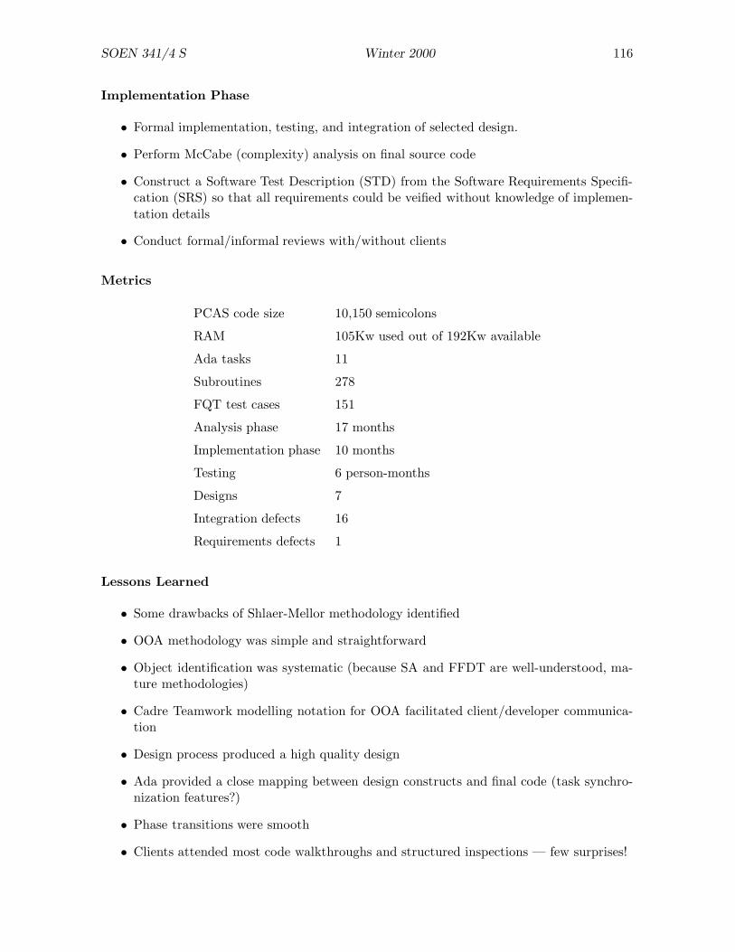
SOEN 341/4 S Winter 2000 116
Implementation Phase
• Formal implementation, testing, and integration of selected design.
• Perform McCabe (complexity) analysis on final source code
• Construct a Software Test Description (STD) from the Software Requirements Specifi-cation (SRS) so that all requirements could be veified without knowledge of implemen-tation details
• Conduct formal/informal reviews with/without clients
Metrics
PCAS code size 10,150 semicolons
RAM 105Kw used out of 192Kw available
Ada tasks 11
Subroutines 278
FQT test cases 151
Analysis phase 17 months
Implementation phase 10 months
Testing 6 person-months
Designs 7
Integration defects 16
Requirements defects 1
Lessons Learned
• Some drawbacks of Shlaer-Mellor methodology identified
• OOA methodology was simple and straightforward
• Object identification was systematic (because SA and FFDT are well-understood, ma-ture methodologies)
• Cadre Teamwork modelling notation for OOA facilitated client/developer communica-tion
• Design process produced a high quality design
• Ada provided a close mapping between design constructs and final code (task synchro-nization features?)
• Phase transitions were smooth
• Clients attended most code walkthroughs and structured inspections — few surprises!

SOEN 341/4 S Winter 2000 117
14 Industrial Practices
14.1 Measurement: COCOMO
COCOMO (COnstructive COst MOdel) is a system for estimating software costs. Measure-ment techniques and cost estimation are discussed fully in other courses; the brief introductionprovided here is intended to help you to understand Question 1 of Assignment 4.
COCOMO was originally described by Barry Boehm in 1981 (Software Engineering Eco-nomics, Prentice Hall). Since 1981, it has been extensively refined; the current version iscalled COCOMO II.
The simplest form, Basic COCOMO, is based on the formula
E = bSc
in which E denotes effort, S denotes the estimated size of the project (this can be measuredin KLOCs (thousands of lines of code), function points, or some other way), and b and c areconstants that depend on the kind of project. The following table shows suitable values for band c for the three main kinds of project.
• An organic project is developed by a small, experienced team working in a familiarenvironment.
• An embedded project is part of a system with a highly constrained environment, suchas air traffic control, that is developed by an experienced team.
• A semidetached project is intermediate between organic and embedded.
Project type b c
organic 2.4 1.05
semidetached 3.0 1.12
embedded 3.6 1.20
The next table shows the effort for projects of various sizes and kinds.
KLOC organic semidetached embedded
1 2.4 3.0 3.6
10 26.9 39.6 57.1
100 302.1 521.3 904.2
1000 3390.0 6872.0 14333.0
Intermediate COCOMO takes into account a number of factors other than the kind of projectand the number of lines of code. They are based on fifteen or so attributes called cost driversbecause they are assumed to affect productivity and hence costs. The COCOMO modeldefines a set of factors for each cost driver. Here is one example:

SOEN 341/4 S Winter 2000 118
Cost driver very low low nominal high very high extra high
Product complexity 0.70 0.85 1.00 1.15 1.30 1.65
We start by estimating the complexity of the product. If we think it is “very low”, then wemultiply the effort estimate by 0.70; if we think is is high, we multiply the cost estimate by1.15; and so on. Obviously, we are guessing to some extent but, as we gain experience, ourguesses should improve. Since most companies produce a limited number of kinds of software,their guesses can eventually become quite accurate.
Here are the other cost drivers:
Product attributes: reliability required; database size; product complexity.
Computer attributes: execution time constraints; main storage constraints; virtual ma-chine volatility; computer turnaround time.
Personnel attributes: analyst capability; applications experience; programmer capability;virtual machine experience; programming language experience.
Project attributes: use of modern programming techniques; use of software tools; requireddevelopment schedule.
The basic formula becomes
E = bSc m(X)
where X is a vector derived from the cost drivers and m is a weighting function.
To use COCOMO properly, you have to know how to choose values for all the cost drivers.There is not space or time to do that here, so we just note the following for personnel expe-rience:
Experience months weight
Extra low less than 3 1.29
Very low 3 to 5 1.29
Low 5 to 9 1.13
Nominal 9 to 12 1.00
High 12 to 24 0.91
Very high 24 to 48 0.82
Extra high more than 48 0.82
Detailed COCOMO uses the same cost drivers but splits them up according to developmentphases or stages. During the first stage, application composition, complexity is measured inobject points. During the second stage, early design, complexity is measured in function points.During the last stage, postarchitecture, complexity is measured in LOCs.
Object points have little to do with object oriented programming: an object point is a screen(or window in modern systems), a report, or a software component (usually a function orprocedure). Function points are like object points but they take a number of additional factorsinto account: the number of inputs and outputs; the number of links between components;and so on.
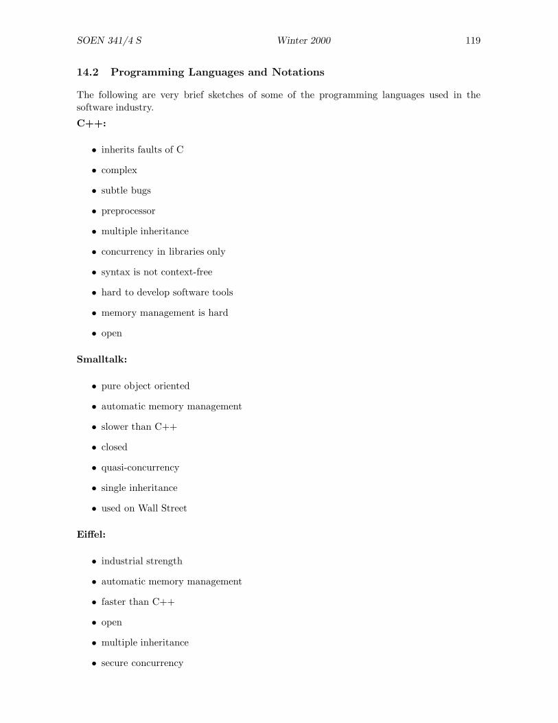
SOEN 341/4 S Winter 2000 119
14.2 Programming Languages and Notations
The following are very brief sketches of some of the programming languages used in thesoftware industry.
C++:
• inherits faults of C
• complex
• subtle bugs
• preprocessor
• multiple inheritance
• concurrency in libraries only
• syntax is not context-free
• hard to develop software tools
• memory management is hard
• open
Smalltalk:
• pure object oriented
• automatic memory management
• slower than C++
• closed
• quasi-concurrency
• single inheritance
• used on Wall Street
Eiffel:
• industrial strength
• automatic memory management
• faster than C++
• open
• multiple inheritance
• secure concurrency

SOEN 341/4 S Winter 2000 120
• complete development methodology
• few users (?)
• few vendors
Java:
• C syntax
• interpreted — slow
• platform independent
• single inheritance
• automatic memory management
• insecure concurrency
• badly design (but rapidly changing) libraries
• acceptance growing for small applications
Ada:
• not fully object oriented
• sound concurrency
• no automatic memory management
• used mainly for aerospace and “defence”
• good development tools
• good for Software Engineering
Common LISP Object System (CLOS):
• fully object-oriented
• multiple inheritance (with ordered superclasses)
• multi-dispatching
• before/after functions
• extensible
• automatic memory management
• slower than C++
• good prototyping language

SOEN 341/4 S Winter 2000 121
UML
• Grady Booch wrote Object Oriented Analysis and Design with Applications (1991, re-vised edition, 1994);
• James Rumbaugh designed Object Modelling Technique (OMT), first presented at OOP-SLA in 1987; and
• Ivar Jacobson published Object-Oriented Software Engineering in 1992 and introduced“use cases” to object oriented software development.
• David Harel introduced statecharts.
• A diagramming notation should be simple and precise. UML is quite complex: the“Notation Summary” occupies 60 pages and describes numerous symbols, keywords,and fonts. This is partly due to the origins of UML as a “union” of three separatenotations.
• Because of its complexity, it is hard to use UML in a casual way. Like a programminglanguage, you have to use it intensively for a significant period of time to become familiarwith all of its details.
• Also because of its complexity, it is impractical to use UML as a hand-written notation.To use it effectively you need software that allows you to draw and modify diagramsand to check properties of diagrams.
• Much of UML is defined rather vaguely. There have been many attempts to provide aformal semantics, but none has been very successful so far.
• There is a tremendous variety of software. It is unlikely that any single notation will beeffective for all applications. Yet UML claims to be a universal notation, suited to allconceivable problems.
• Most of the enthusiasm about UML comes from higher management. People who haveto use it are less enthusiastic about its capabilities.
14.3 Theory and Practice
The Role of Theory
• Mathematics: existence and continuity of functions; existence of integral transforms;completeness of functional bases.
• Electrical engineer: obtain steady state response from Fourier transform and transientresponse from Laplace transform.
• Mathematics: completeness and decidability of logics; proof theory; model theory.
• Software designer: practical ways of applying logic???
Software Engineering:
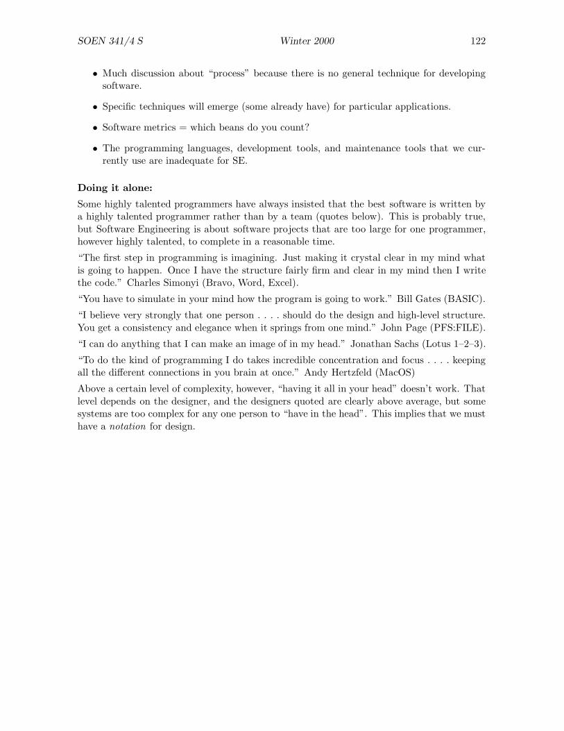
SOEN 341/4 S Winter 2000 122
• Much discussion about “process” because there is no general technique for developingsoftware.
• Specific techniques will emerge (some already have) for particular applications.
• Software metrics = which beans do you count?
• The programming languages, development tools, and maintenance tools that we cur-rently use are inadequate for SE.
Doing it alone:
Some highly talented programmers have always insisted that the best software is written bya highly talented programmer rather than by a team (quotes below). This is probably true,but Software Engineering is about software projects that are too large for one programmer,however highly talented, to complete in a reasonable time.
“The first step in programming is imagining. Just making it crystal clear in my mind whatis going to happen. Once I have the structure fairly firm and clear in my mind then I writethe code.” Charles Simonyi (Bravo, Word, Excel).
“You have to simulate in your mind how the program is going to work.” Bill Gates (BASIC).
“I believe very strongly that one person . . . . should do the design and high-level structure.You get a consistency and elegance when it springs from one mind.” John Page (PFS:FILE).
“I can do anything that I can make an image of in my head.” Jonathan Sachs (Lotus 1–2–3).
“To do the kind of programming I do takes incredible concentration and focus . . . . keepingall the different connections in you brain at once.” Andy Hertzfeld (MacOS)
Above a certain level of complexity, however, “having it all in your head” doesn’t work. Thatlevel depends on the designer, and the designers quoted are clearly above average, but somesystems are too complex for any one person to “have in the head”. This implies that we musthave a notation for design.
![[PPT]PowerPoint Presentation - Hadi Soen | Sinuba … · Web viewSTATISTIKA HADI SUNARTO, SPd Email: hadisoen66@yahoo.com*](https://img.dokumen.tips/doc/110x75/5b9c13aa09d3f2f94c8be8b1/pptpowerpoint-presentation-hadi-soen-sinuba-web-viewstatistika-hadi-sunarto.jpg)


![Contentsusers.encs.concordia.ca/~grogono/procbibrep.pdf[2] Peter Grogono. The Evolution of Programming Languages. Jyv askyl a Summer School 1999, Univer-sity of Jyv askyl a, Finland,](https://img.dokumen.tips/doc/110x75/5ec62a8dc706d66909187f6b/grogonoprocbibreppdf-2-peter-grogono-the-evolution-of-programming-languages.jpg)